Embed Size (px)
Citation preview
33
Heavy Bridge Forming
33 – 41
MB0113www.MeadowBurke.com MeadowBurke®
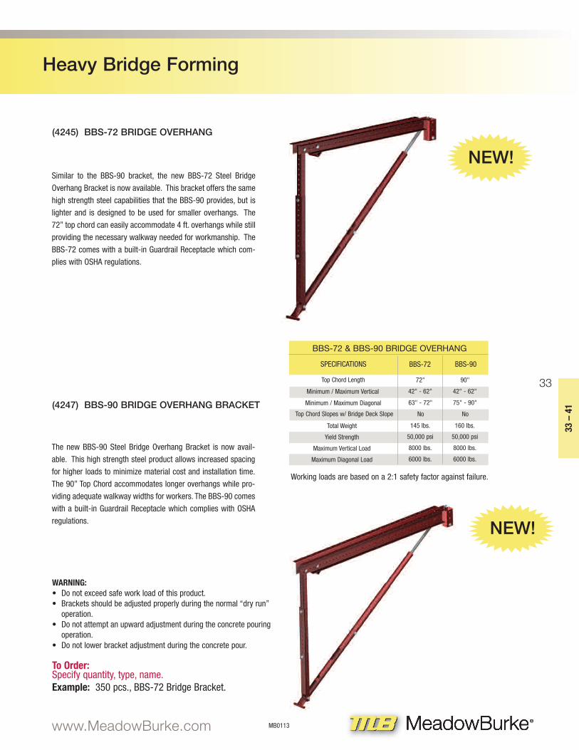
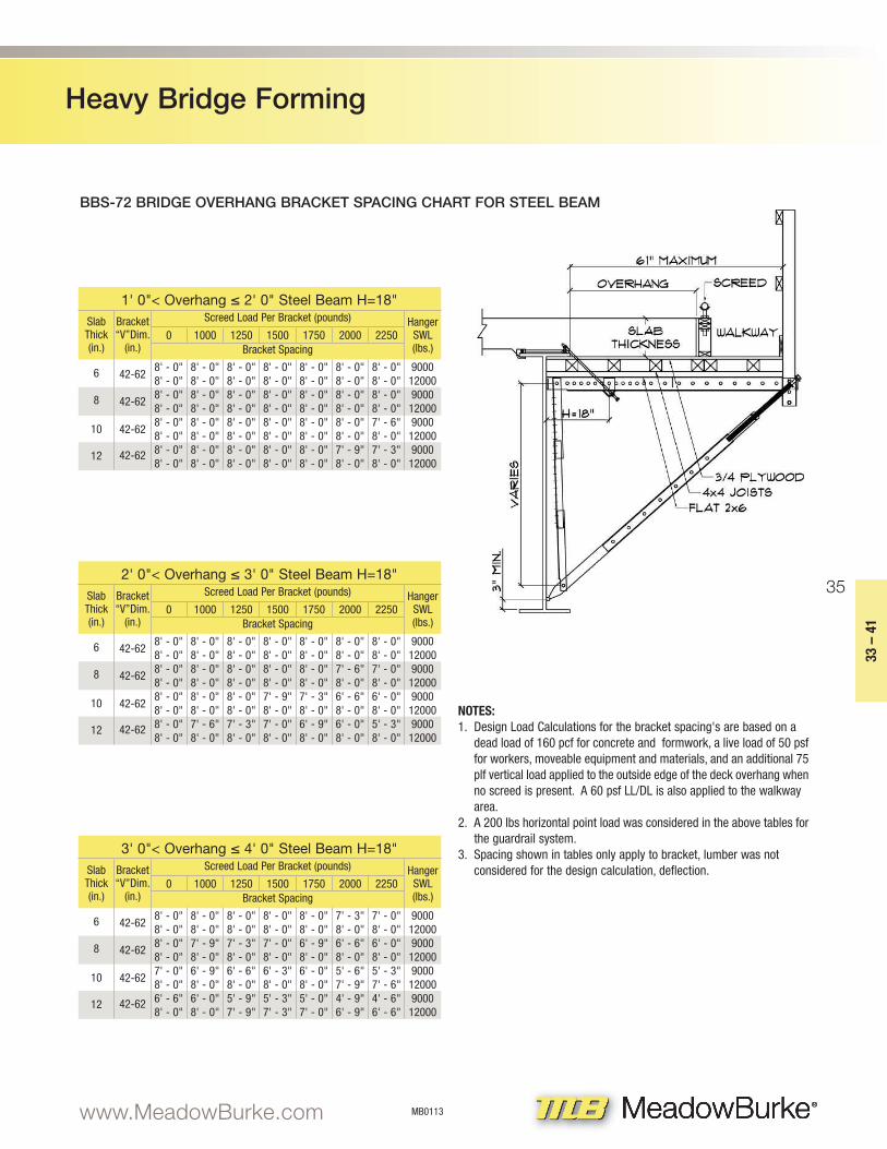
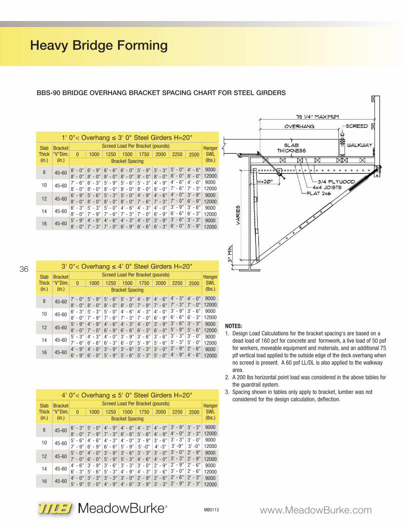
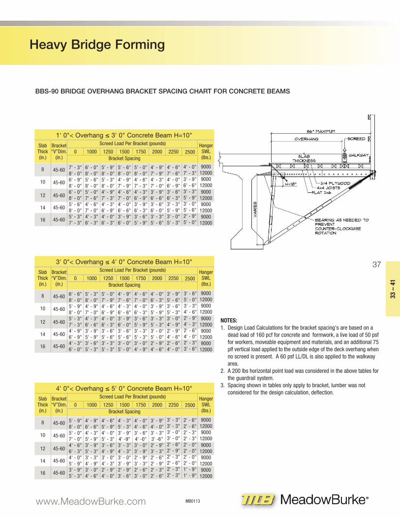
(4247) BBS-90 BRIDGE OVERHANG BRACKET
The new BBS-90 Steel Bridge Overhang Bracket is now avail-
able. This high strength steel product allows increased spacing
for higher loads to minimize material cost and installation time.
The 90” Top Chord accommodates longer overhangs while pro-
viding adequate walkway widths for workers. The BBS-90 comes
with a built-in Guardrail Receptacle which complies with OSHA
regulations.
(4245) BBS-72 BRIDGE OVERHANG
Similar to the BBS-90 bracket, the new BBS-72 Steel Bridge
Overhang Bracket is now available. This bracket offers the same
high strength steel capabilities that the BBS-90 provides, but is
lighter and is designed to be used for smaller overhangs. The
72” top chord can easily accommodate 4 ft. overhangs while still
providing the necessary walkway needed for workmanship. The
BBS-72 comes with a built-in Guardrail Receptacle which com-
plies with OSHA regulations.
WARNING:• Do not exceed safe work load of this product.• Brackets should be adjusted properly during the normal “dry run”
operation.• Do not attempt an upward adjustment during the concrete pouring
operation.• Do not lower bracket adjustment during the concrete pour.
To Order:Specify quantity, type, name.Example: 350 pcs., BBS-72 Bridge Bracket.
SPECIFICATIONS
BBS-72 & BBS-90 BRIDGE OVERHANG
BBS-72 BBS-90
Top Chord Length 72"
Minimum / Maximum Vertical 42" - 62"
Minimum / Maximum Diagonal 63" - 72"
Top Chord Slopes w/ Bridge Deck Slope No
Total Weight 145 lbs.
Yield Strength 50,000 psi
Maximum Vertical Load 8000 lbs.
Maximum Diagonal Load 6000 lbs.
90"
42" - 62"
75" - 90"
No
160 lbs.
50,000 psi
8000 lbs.
6000 lbs.
NEW!
NEW!
Working loads are based on a 2:1 safety factor against failure.
34
Heavy Bridge Forming
MB0113 www.MeadowBurke.comMeadowBurke®
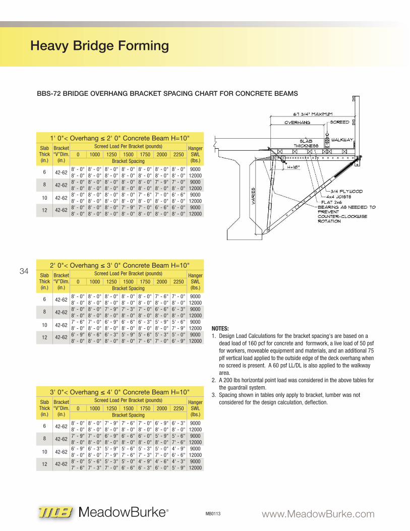
BBS-72 BRIDGE OVERHANG BRACKET SPACING CHART FOR CONCRETE BEAMS
2' 0"< Overhang ≤ 3' 0" Concrete Beam H=10"SlabThick(in.)
Bracket “V”Dim.
(in.)0
8' - 0"8' - 0"8' - 0"8' - 0"7' - 6"8' - 0"6' - 9"8' - 0"
6
8
10
12
8' - 0"8' - 0"8' - 0"8' - 0"7' - 0"8' - 0"6' - 6"8' - 0"
8' - 0"8' - 0"7' - 9"8' - 0"6' - 9"8' - 0"6' - 3"8' - 0"
8' - 0"8' - 0"7' - 3"8' - 0"6' - 6"8' - 0"5' - 9"8' - 0"
8' - 0"8' - 0"7' - 0"8' - 0"6' - 3"8' - 0"5' - 6"7' - 6"
7' - 6"8' - 0"6' - 6"8' - 0"5' - 9"8' - 0"5' - 3"7' - 0"
7' - 0"8' - 0"6' - 3"8' - 0"5' - 6"7' - 9"5' - 0"6' - 9"
9000120009000
120009000
120009000
12000
1000 1250 1500 1750 2000 2250
Screed Load Per Bracket (pounds)
Bracket Spacing
HangerSWL(lbs.)
42-62
42-62
42-62
42-62
1' 0"< Overhang ≤ 2' 0" Concrete Beam H=10"SlabThick(in.)
Bracket “V”Dim.
(in.)0
8' - 0"8' - 0"8' - 0"8' - 0"8' - 0"8' - 0"8' - 0"8' - 0"
6
8
10
12
8' - 0"8' - 0"8' - 0"8' - 0"8' - 0"8' - 0"8' - 0"8' - 0"
8' - 0"8' - 0"8' - 0"8' - 0"8' - 0"8' - 0"8' - 0"8' - 0"
8' - 0"8' - 0"8' - 0"8' - 0"8' - 0"8' - 0"7' - 9"8' - 0"
8' - 0"8' - 0"8' - 0"8' - 0"7' - 6"8' - 0"7' - 0"8' - 0"
8' - 0"8' - 0"7' - 9"8' - 0"7' - 0"8' - 0"6' - 6"8' - 0"
8' - 0"8' - 0"7' - 0"8' - 0"6' - 6"8' - 0"6' - 0"8' - 0"
9000120009000
120009000
120009000
12000
1000 1250 1500 1750 2000 2250
Screed Load Per Bracket (pounds)
Bracket Spacing
HangerSWL(lbs.)
42-62
42-62
42-62
42-62
3' 0"< Overhang ≤ 4' 0" Concrete Beam H=10"SlabThick(in.)
Bracket “V”Dim.
(in.)0
8' - 0"8' - 0"7' - 9"8' - 0"6' - 9"8' - 0"8' - 0"7' - 6"
6
8
10
12
8' - 0"8' - 0"7' - 0"8' - 0"6' - 3"8' - 0"5' - 6"7' - 3"
7' - 9"8' - 0"6' - 9"8' - 0"5' - 9"7' - 9"5' - 3"7' - 0"
7' - 6"8' - 0"6' - 6"8' - 0"5' - 6"7' - 6"5' - 0"6' - 6"
7' - 0"8' - 0"6' - 0"8' - 0"5' - 3"7' - 3"4' - 9"6' - 3"
6' - 9"8' - 0"5' - 9"8' - 0"5' - 0"7' - 0"4' - 6"6' - 0"
6' - 3"8' - 0"5' - 6"7' - 6"4' - 9"6' - 6"4' - 3"5' - 9"
9000120009000
120009000
120009000
12000
1000 1250 1500 1750 2000 2250
Screed Load Per Bracket (pounds)
Bracket Spacing
HangerSWL(lbs.)
42-62
42-62
42-62
42-62
NOTES:1. Design Load Calculations for the bracket spacing's are based on a
dead load of 160 pcf for concrete and formwork, a live load of 50 psf for workers, moveable equipment and materials, and an additional 75 plf vertical load applied to the outside edge of the deck overhang when no screed is present. A 60 psf LL/DL is also applied to the walkway area.
2. A 200 lbs horizontal point load was considered in the above tables for the guardrail system.
3. Spacing shown in tables only apply to bracket, lumber was not considered for the design calculation, deflection.
35
Heavy Bridge Forming
33 – 41
MB0113www.MeadowBurke.com MeadowBurke®
BBS-72 BRIDGE OVERHANG BRACKET SPACING CHART FOR STEEL BEAM
2' 0"< Overhang ≤ 3' 0" Steel Beam H=18"SlabThick(in.)
Bracket “V”Dim.
(in.)0
8' - 0"8' - 0"8' - 0"8' - 0"8' - 0"8' - 0"8' - 0"8' - 0"
6
8
10
12
8' - 0"8' - 0"8' - 0"8' - 0"8' - 0"8' - 0"7' - 6"8' - 0"
8' - 0"8' - 0"8' - 0"8' - 0"8' - 0"8' - 0"7' - 3"8' - 0"
8' - 0"8' - 0"8' - 0"8' - 0"7' - 9"8' - 0"7' - 0"8' - 0"
8' - 0"8' - 0"8' - 0"8' - 0"7' - 3"8' - 0"6' - 9"8' - 0"
8' - 0"8' - 0"7' - 6"8' - 0"6' - 6"8' - 0"6' - 0"8' - 0"
8' - 0"8' - 0"7' - 0"8' - 0"6' - 0"8' - 0"5' - 3"8' - 0"
9000120009000
120009000
120009000
12000
1000 1250 1500 1750 2000 2250
Screed Load Per Bracket (pounds)
Bracket Spacing
HangerSWL(lbs.)
NOTES:1. Design Load Calculations for the bracket spacing's are based on a
dead load of 160 pcf for concrete and formwork, a live load of 50 psf for workers, moveable equipment and materials, and an additional 75 plf vertical load applied to the outside edge of the deck overhang when no screed is present. A 60 psf LL/DL is also applied to the walkway area.
2. A 200 lbs horizontal point load was considered in the above tables for the guardrail system.
3. Spacing shown in tables only apply to bracket, lumber was not considered for the design calculation, deflection.
42-62
42-62
42-62
42-62
1' 0"< Overhang ≤ 2' 0" Steel Beam H=18"SlabThick(in.)
Bracket “V”Dim.
(in.)0
8' - 0"8' - 0"8' - 0"8' - 0"8' - 0"8' - 0"8' - 0"8' - 0"
6
8
10
12
8' - 0"8' - 0"8' - 0"8' - 0"8' - 0"8' - 0"8' - 0"8' - 0"
8' - 0"8' - 0"8' - 0"8' - 0"8' - 0"8' - 0"8' - 0"8' - 0"
8' - 0"8' - 0"8' - 0"8' - 0"8' - 0"8' - 0"8' - 0"8' - 0"
8' - 0"8' - 0"8' - 0"8' - 0"8' - 0"8' - 0"8' - 0"8' - 0"
8' - 0"8' - 0"8' - 0"8' - 0"8' - 0"8' - 0"7' - 9"8' - 0"
8' - 0"8' - 0"8' - 0"8' - 0"7' - 6"8' - 0"7' - 3"8' - 0"
9000120009000
120009000
120009000
12000
1000 1250 1500 1750 2000 2250
Screed Load Per Bracket (pounds)
Bracket Spacing
HangerSWL(lbs.)
42-62
42-62
42-62
42-62
3' 0"< Overhang ≤ 4' 0" Steel Beam H=18"SlabThick(in.)
Bracket “V”Dim.
(in.)0
8' - 0"8' - 0"8' - 0"8' - 0"7' - 0"8' - 0"6' - 6"8' - 0"
6
8
10
12
8' - 0"8' - 0"7' - 9"8' - 0"6' - 9"8' - 0"6' - 0"8' - 0"
8' - 0"8' - 0"7' - 3"8' - 0"6' - 6"8' - 0"5' - 9"7' - 9"
8' - 0"8' - 0"7' - 0"8' - 0"6' - 3"8' - 0"5' - 3"7' - 3"
8' - 0"8' - 0"6' - 9"8' - 0"6' - 0"8' - 0"5' - 0"7' - 0"
7' - 3"8' - 0"6' - 6"8' - 0"5' - 6"7' - 9"4' - 9"6' - 9"
7' - 0"8' - 0"6' - 0"8' - 0"5' - 3"7' - 6"4' - 6"6' - 6"
9000120009000
120009000
120009000
12000
1000 1250 1500 1750 2000 2250
Screed Load Per Bracket (pounds)
Bracket Spacing
HangerSWL(lbs.)
42-62
42-62
42-62
42-62
36
Heavy Bridge Forming
MB0113 www.MeadowBurke.comMeadowBurke®
BBS-90 BRIDGE OVERHANG BRACKET SPACING CHART FOR STEEL GIRDERS
1' 0"< Overhang ≤ 3' 0" Steel Girders H=20"
SlabThick(in.)
Bracket “V”Dim.
(in.)0
8' - 0"8' - 0"7' - 6"8' - 0"6' - 9"8' - 0"6' - 3"8' - 0"5' - 9"8' - 0"
8
10
12
14
6' - 9"8' - 0"6' - 3"8' - 0"5' - 6"8' - 0"5' - 3"7' - 9"4' - 9"7' - 3"
6' - 6"8' - 0"5' - 9"8' - 0"5' - 3"8' - 0"5' - 0"7' - 6"4' - 6"7' - 0"
6' - 0"8' - 0"5' - 6"8' - 0"5' - 0"8' - 0"4' - 6"7' - 3"4' - 3"6' - 9"
5' - 9"8' - 0"5' - 3"8' - 0"4' - 9"7' - 6"4' - 3"7' - 0"4' - 0"6' - 6"
5' - 3"8' - 0"4' - 9"8' - 0"4' - 6"7' - 3"4' - 0"6' - 9"3' - 9"6' - 3"
5' - 0"8' - 0"4' - 6"7' - 6"4' - 0"7' - 0"3' - 9"6' - 6"3' - 6"6' - 0"
9000120009000
120009000
120009000
120009000
12000
1000 1250 1500 1750 2000 2250
4' - 6"8' - 0"4' - 0"7' - 3"3' - 9"6' - 9"3' - 6"6' - 3"3' - 3"5' - 9"
2500
Screed Load Per Bracket (pounds)
Bracket Spacing
HangerSWL(lbs.)
45-60
45-60
45-60
45-60
16 45-60
3' 0"< Overhang ≤ 4' 0" Steel Girders H=20"
SlabThick(in.)
Bracket “V”Dim.
(in.)0
7' - 0"8' - 0"6' - 3"8' - 0"5' - 9"8' - 0"5' - 3"7' - 6"4' - 9"6' - 9"
8
10
12
14
5' - 9"8' - 0"5' - 3"7' - 9"4' - 9"7' - 0"4' - 3"6' - 6"4' - 0"6' - 0"
5' - 6"8' - 0"5' - 0"7' - 6"4' - 6"6' - 9"4' - 0"6' - 3"3' - 9"5' - 9"
5' - 3"8' - 0"4' - 6"7' - 3"4' - 3"6' - 6"3' - 9"6' - 0"3' - 6"5' - 6"
4' - 9"7' - 9"4' - 3"7' - 0"4' - 0"6' - 3"3' - 6"5' - 9"3' - 3"5' - 3"
4' - 6"7' - 6"4' - 0"6' - 9"3' - 9"6' - 0"3' - 6"5' - 6"3' - 0"5' - 0"
4' - 3"7' - 3"3' - 9"6' - 6"3' - 6"5' - 9"3' - 3"5' - 3"2' - 9"4' - 9"
9000120009000
120009000
120009000
120009000
12000
1000 1250 1500 1750 2000 2250
4' - 0"7' - 0"3' - 6"6' - 3"3' - 3"5' - 6"3' - 0"5' - 0"2' - 6"4' - 6"
2500
Screed Load Per Bracket (pounds)
Bracket Spacing
HangerSWL(lbs.)
45-60
45-60
45-60
45-60
16 45-60
4' 0"< Overhang ≤ 5' 0" Steel Girders H=20"
SlabThick(in.)
Bracket “V”Dim.
(in.)0
6' - 3"8' - 0"5' - 6"7' - 9"5' - 0"7' - 0"4' - 6"6' - 3"4' - 0"5' - 9"
8
10
12
14
5' - 0"7' - 9"4' - 6"6' - 9"4' - 0"6' - 0"3' - 9"5' - 6"3' - 3"5' - 0"
4' - 9"7' - 3"4' - 3"6' - 6"3' - 9"5' - 9"3' - 6"5' - 3"3' - 3"4' - 9"
4' - 6"6' - 6"4' - 0"5' - 9"3' - 6"5' - 3"3' - 3"4' - 9"3' - 0"4' - 6"
4' - 3"5' - 6"3' - 9"5' -0"3' - 3"4' - 6"3' - 0"4' - 3"2' - 9"3' - 9"
4' - 0"4' - 9"3' - 6"4' -3"3' - 0"4' - 0"2' - 9"3' - 6"2' - 6"3' - 3"
3' - 9"4' - 0"3' - 3"3' -9"3' - 0"3' - 3"2' - 9"3' - 0"2' - 6"2' - 9"
9000120009000
120009000
120009000
120009000
12000
1000 1250 1500 1750 2000 2250
3' - 3"3' - 3"3' - 0"3' -0"2' - 9"2' - 9"2' - 6"2' - 6"2' - 3"2' - 3"
2500
Screed Load Per Bracket (pounds)
Bracket Spacing
HangerSWL(lbs.)
45-60
45-60
45-60
45-60
16 45-60
NOTES:1. Design Load Calculations for the bracket spacing's are based on a
dead load of 160 pcf for concrete and formwork, a live load of 50 psf for workers, moveable equipment and materials, and an additional 75 plf vertical load applied to the outside edge of the deck overhang when no screed is present. A 60 psf LL/DL is also applied to the walkway area.
2. A 200 lbs horizontal point load was considered in the above tables for the guardrail system.
3. Spacing shown in tables only apply to bracket, lumber was not considered for the design calculation, deflection.
37
Heavy Bridge Forming
33 – 41
MB0113www.MeadowBurke.com MeadowBurke®
BBS-90 BRIDGE OVERHANG BRACKET SPACING CHART FOR CONCRETE BEAMS
1' 0"< Overhang ≤ 3' 0" Concrete Beam H=10"
SlabThick(in.)
Bracket “V”Dim.
(in.)0
7' - 3"8' - 0"6' - 9"8' - 0"6' - 0"8' - 0"5' - 6"8' - 0"5' - 3"7' - 3"
8
10
12
14
6' - 0"8' - 0"5' - 6"8' - 0"5' - 0"7' - 6"4' - 6"7' - 0"4' - 3"6' - 3"
5' - 9"8' - 0"5' - 3"8' - 0"4' - 9"7' - 3"4' - 3"6' - 9"4' - 0"6' - 3"
5' - 6"8' - 0"4' - 9"7' - 9"4' - 6"7' - 0"4' - 0"6' - 6"3' - 9"6' - 0"
5' - 0"8' - 0"4' - 6"7' - 3"4' - 3"6' - 9"3' - 9"6' - 3"3' - 6"5' - 9"
4' - 9"7' - 9"4' - 3"7' - 0"3' - 9"6' - 6"3' - 6"6' - 0"3' - 3"5' - 6"
4' - 6"7' - 6"4' - 0"6' - 9"3' - 6"6' - 3"3' - 3"5' - 9"3' - 0"5' - 3"
9000120009000
120009000
120009000
120009000
12000
1000 1250 1500 1750 2000 2250
4' - 0"7' - 3"3' - 9"6' - 6"3' - 3"5' - 9"3' - 0"5' - 6"2' - 9"5' - 0"
2500
Screed Load Per Bracket (pounds)
Bracket Spacing
HangerSWL(lbs.)
45-60
45-60
45-60
45-60
16 45-60
3' 0"< Overhang ≤ 4' 0" Concrete Beam H=10"
SlabThick(in.)
Bracket “V”Dim.
(in.)0
6' - 6"8' - 0"5' - 9"8' - 0"5' - 3"7' - 3"4' - 9"6' - 9"4' - 3"6' - 0"
8
10
12
14
5' - 3"8' - 0"4' - 9"7' - 0"4' - 3"6' - 6"3' - 9"5' - 9"3' - 6"5' - 3"
5' - 0"7' - 9"4' - 6"6' - 9"4' - 0"6' - 3"3' - 6"5' - 6"3' - 3"5' - 3"
4' - 9"7' - 6"4' - 3"6' - 6"3' - 9"6' - 0"3' - 6"5' - 6"3' - 0"5' - 0"
4' - 6"7' - 0"4' - 0"6' - 3"3' - 6"5' - 9"3' - 3"5' - 3"3' - 0"4' - 9"
4' - 0"6' - 3"3' - 9"5' - 9"3' - 3"5' - 3"3' - 0"5' - 0"2' - 9"4' - 6"
3' - 9"5' - 6"3' - 6"5' - 3"3' - 0"4' - 9"2' - 9"4' - 6"2' - 6"4' - 0"
9000120009000
120009000
120009000
120009000
12000
1000 1250 1500 1750 2000 2250
3' - 6"5' - 0"3' - 3"4' - 6"2' - 9"4' - 3"2' - 6"4' - 0"2' - 3"3' - 6"
2500
Screed Load Per Bracket (pounds)
Bracket Spacing
HangerSWL(lbs.)
45-60
45-60
45-60
45-60
16 45-60
4' 0"< Overhang ≤ 5' 0" Concrete Beam H=10"
SlabThick(in.)
Bracket “V”Dim.
(in.)0
5' - 9"8' - 0"5' - 0"7' - 0"4' - 6"6' - 3"4' - 0"5' - 9"3' - 9"5' - 3"
8
10
12
14
4' - 9"6' - 6"4' - 3"5' - 9"3' - 9"5' - 3"3' - 3"4' - 9"3' - 0"4' - 6"
4' - 6"5' - 9"4' - 0"5' - 3"3' - 6"4' - 9"3' - 0"4' - 3"2' - 9"4' - 0"
4' - 3"5' - 3"3' - 9"4' -9"3' - 3"4' - 3"3' - 0"3' - 9"2' - 9"3' - 6"
4' - 0"4' - 6"3' - 6"4' -0"3' - 0"3' - 9"2' - 9"3' - 3"2' - 6"3' - 0"
3' - 9"4' - 0"3' - 3"3' -6"2' - 9"3' - 3"2' - 6"2' - 9"2' - 3"2' - 6"
3' - 3"3' - 3"3' - 0"3' - 0"2' - 6"2' - 9"2' - 3"2' - 6"2' - 3"2' - 3"
9000120009000
120009000
120009000
120009000
12000
1000 1250 1500 1750 2000 2250
2' - 6"2' - 6"2' - 3"2' - 3"2' - 0"2' - 0"2' - 0"2' - 0"1' - 9"1' - 9"
2500
Screed Load Per Bracket (pounds)
Bracket Spacing
HangerSWL(lbs.)
45-60
45-60
45-60
45-60
16 45-60
NOTES:1. Design Load Calculations for the bracket spacing's are based on a
dead load of 160 pcf for concrete and formwork, a live load of 50 psf for workers, moveable equipment and materials, and an additional 75 plf vertical load applied to the outside edge of the deck overhang when no screed is present. A 60 psf LL/DL is also applied to the walkway area.
2. A 200 lbs horizontal point load was considered in the above tables for the guardrail system.
3. Spacing shown in tables only apply to bracket, lumber was not considered for the design calculation, deflection.
38
Heavy Bridge Forming
MB0113 www.MeadowBurke.comMeadowBurke®
FEATURES
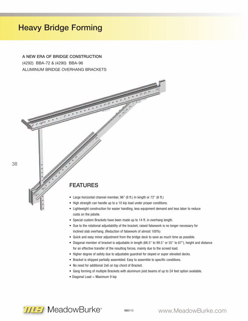
• Large horizontal channel member, 96” (8 ft.) in length or 72" (6 ft.)
• High strength can handle up to a 10 kip load under proper conditions.
• Lightweight construction for easier handling, less equipment demand and less labor to reduce
costs on the jobsite.
• Special custom Brackets have been made up to 14 ft. in overhang length.
• Due to the rotational adjustability of the bracket, raised falsework is no longer necessary for
inclined slab overhang. (Reduction of falsework of almost 100%)
• Quick and easy minor adjustment from the bridge deck to save as much time as possible.
• Diagonal member of bracket is adjustable in length (66.5" to 99.5" or 55" to 67"), height and distance
for an effective transfer of the resulting forces, mainly due to the screed load.
• Higher degree of safety due to adjustable guardrail for sloped or super elevated decks.
• Bracket is shipped partially assembled. Easy to assemble to specific conditions.
• No need for additional 2x6 on top chord of Bracket.
• Gang forming of multiple Brackets with aluminum joist beams of up to 24 feet option available.
• Diagonal Load = Maximum 9 kip
A NEW ERA OF BRIDGE CONSTRUCTION
(4292) BBA-72 & (4290) BBA-96
ALUMINUM BRIDGE OVERHANG BRACKETS
39
Heavy Bridge Forming
33 – 41
MB0113www.MeadowBurke.com MeadowBurke®
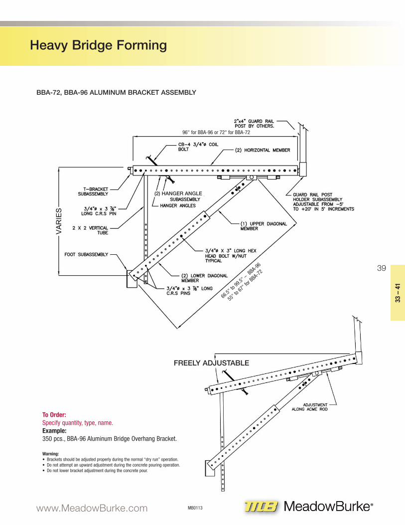
BBA-72, BBA-96 ALUMINUM BRACKET ASSEMBLY
To Order:Specify quantity, type, name.Example:350 pcs., BBA-96 Aluminum Bridge Overhang Bracket.
Warning: • Brackets should be adjusted properly during the normal “dry run” operation.• Do not attempt an upward adjustment during the concrete pouring operation.• Do not lower bracket adjustment during the concrete pour.
(2) HANGER ANGLE
FREELY ADJUSTABLE
96" for BBA-96 or 72" for BBA-72
66.5" to 99.5" –
BBA-96
55" to 67" f
or BBA-72
40
Heavy Bridge Forming
MB0113 www.MeadowBurke.comMeadowBurke®
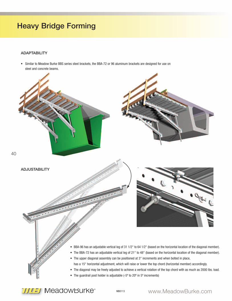
• BBA-96 has an adjustable vertical leg of 31 1/2" to 64 1/2" (based on the horizontal location of the diagonal member).
• The BBA-72 has an adjustable vertical leg of 21" to 48" (based on the horizontal location of the diagonal member).
• The upper diagonal assembly can be positioned at 3" increments and when bolted in place,
has a 15" horizontal adjustment, which will raise or lower the top chord (horizontal member) accordingly.
• The diagonal may be freely adjusted to achieve a vertical rotation of the top chord with as much as 2000 lbs. load.
• The guardrail post holder is adjustable (-5º to 20º in 5º increments)
ADAPTABILITY
ADJUSTABILITY
• Similar to Meadow Burke BBS series steel brackets, the BBA-72 or 96 aluminum brackets are designed for use on
steel and concrete beams.
41
Heavy Bridge Forming
33 – 41
MB0113www.MeadowBurke.com MeadowBurke®
20.00
17.50
15.00
12.50
10.00
7.50
5.00
2.50
0.00
Load vs. ∆ Curve
0 0.25 0.5 0.75 1 1.25 1.5 1.75 2
20.00
17.50
15.00
12.50
10.00
7.50
5.00
2.50
0.00
Load vs. ∆ Curve
0 0.25 0.5 0.75 1 1.25 1.5 1.75 2
20.00
17.50
15.00
12.50
10.00
7.50
5.00
2.50
0.00
Load vs. ∆ Curve
0 0.25 0.5 0.75 1 1.25 1.5 1.75 2
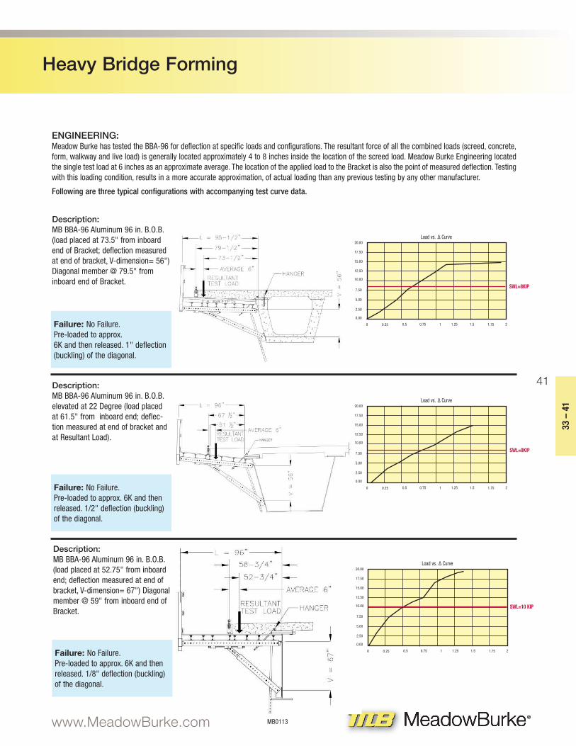
ENGINEERING: Meadow Burke has tested the BBA-96 for deflection at specific loads and configurations. The resultant force of all the combined loads (screed, concrete,form, walkway and live load) is generally located approximately 4 to 8 inches inside the location of the screed load. Meadow Burke Engineering locatedthe single test load at 6 inches as an approximate average. The location of the applied load to the Bracket is also the point of measured deflection. Testingwith this loading condition, results in a more accurate approximation, of actual loading than any previous testing by any other manufacturer.
Following are three typical configurations with accompanying test curve data.
Description:MB BBA-96 Aluminum 96 in. B.O.B.(load placed at 73.5" from inboardend of Bracket; deflection measuredat end of bracket, V-dimension= 56")Diagonal member @ 79.5" frominboard end of Bracket.
Description:MB BBA-96 Aluminum 96 in. B.O.B.elevated at 22 Degree (load placedat 61.5" from inboard end; deflec-tion measured at end of bracket andat Resultant Load).
Description:MB BBA-96 Aluminum 96 in. B.O.B.(load placed at 52.75" from inboardend; deflection measured at end ofbracket, V-dimension= 67") Diagonalmember @ 59" from inboard end ofBracket.
Failure: No Failure. Pre-loaded to approx. 6K and then released. 1" deflection(buckling) of the diagonal.
Failure: No Failure. Pre-loaded to approx. 6K and thenreleased. 1/2" deflection (buckling)of the diagonal.
Failure: No Failure. Pre-loaded to approx. 6K and thenreleased. 1/8" deflection (buckling)of the diagonal.
SWL=8KIP
SWL=8KIP
SWL=10 KIP
42
Heavy Bridge Forming
MB0113 www.MeadowBurke.comMeadowBurke®
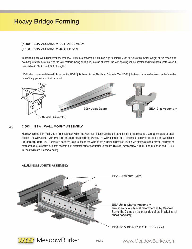
(4300) BBA-ALUMINUM CLIP ASSEMBLY
(4310) BBA-ALUMINUM JOIST BEAM
ALUMINUM JOISTS ASSEMBLY
In addition to the Aluminum Brackets, Meadow Burke also provides a 5.50 inch high Aluminum Joist to reduce the overall weight of the assembled
overhang system. As a result of the joist material being aluminum, instead of wood, the joist spacing will be greater and installation costs lower. It
is available in 18, 21, and 24 foot lengths.
HF-91 clamps are available which secure the HF-92 joist beam to the Aluminum Brackets. The HF-92 joist beam has a nailer insert so the installa-
tion of the plywood is as fast as usual.
BBA-Clip Assembly
BBA Joist Clamp AssemblyTwo at every joist typical recommended by MeadowBurke (the Clamp on the other side of the bracket is notshown for clarity)
BBA-Aluminum Joist
BBA-96 & BBA-72 B.O.B. Top Chord
(4293) BBA - WALL MOUNT ASSEMBLY
Meadow Burke’s BBA-Wall Mount Assembly used when the Aluminum Bridge Overhang Brackets must be attached to a vertical concrete or steel
section. The WMA comes with two parts; the rigid mount and the washer. The WMA replaces the T-Bracket assembly at the end of the Aluminum
Bracket’s top chord. The T-Bracket’s bolts are used to attach the WMA to the Aluminum Bracket. Then WMA attaches to the vertical concrete or
steel section via a slotted hole that accepts a 1” diameter bolt or post installed anchor. The SWL for the WMA is 10,000Lbs in Tension and 10,000
in Shear with a 2:1 factor of safety.
BBA Joist Beam
BBA Wall Assembly
43
Heavy Bridge Forming
33 – 41
MB0113www.MeadowBurke.com MeadowBurke®
AluminumBracket
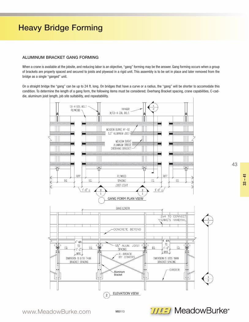
ALUMINUM BRACKET GANG FORMING
When a crane is available at the jobsite, and reducing labor is an objective, “gang” forming may be the answer. Gang forming occurs when a groupof brackets are properly spaced and secured to joists and plywood in a rigid unit. This assembly is to be set in place and later removed from thebridge as a single “ganged” unit.
On a straight bridge the “gang” can be up to 24 ft. long. On bridges that have a curve or a radius, the “gang” will be shorter to accomodate thiscondition. To determine the length of a gang form, the following items must be considered; Overhang Bracket spacing, crane capabilities, C-cad-die, aluminum joist length, job site suitability, and repeatablility.
AluminumBracket
44
Heavy Bridge Forming
MB0113 www.MeadowBurke.comMeadowBurke®
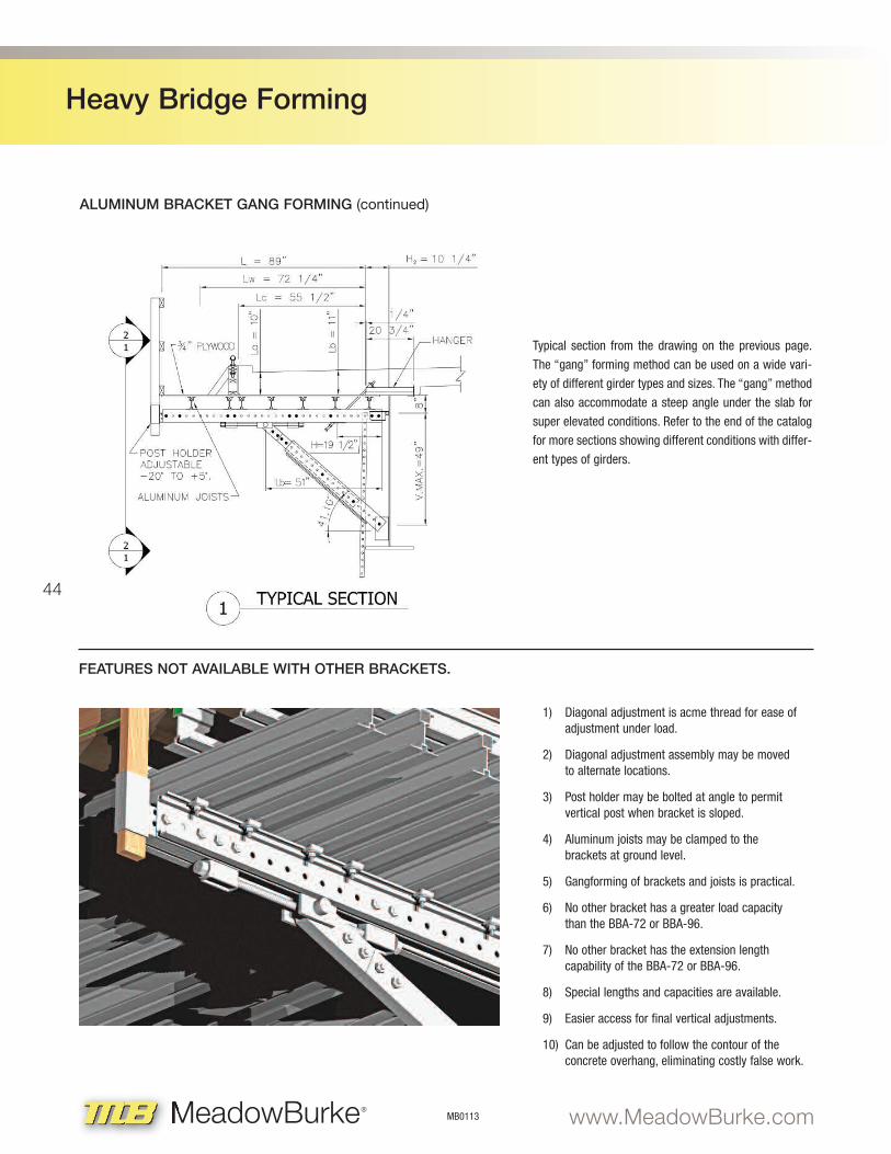
Typical section from the drawing on the previous page.
The “gang” forming method can be used on a wide vari-
ety of different girder types and sizes. The “gang” method
can also accommodate a steep angle under the slab for
super elevated conditions. Refer to the end of the catalog
for more sections showing different conditions with differ-
ent types of girders.
1) Diagonal adjustment is acme thread for ease of adjustment under load.
2) Diagonal adjustment assembly may be moved to alternate locations.
3) Post holder may be bolted at angle to permit vertical post when bracket is sloped.
4) Aluminum joists may be clamped to the brackets at ground level.
5) Gangforming of brackets and joists is practical.
6) No other bracket has a greater load capacity than the BBA-72 or BBA-96.
7) No other bracket has the extension lengthcapability of the BBA-72 or BBA-96.
8) Special lengths and capacities are available.
9) Easier access for final vertical adjustments.
10) Can be adjusted to follow the contour of the concrete overhang, eliminating costly false work.
ALUMINUM BRACKET GANG FORMING (continued)
FEATURES NOT AVAILABLE WITH OTHER BRACKETS.