Embed Size (px)
Citation preview
REPLACEMENT OF AMTRAK MOVABLE BRIDGE 116.74OVER THE NIANTIC RIVER
Craig J. Rolwood, PE Peter FinchNational Railroad Passenger Corporation National Railroad Passenger CorporationAmtrak Amtrak30th Street Station 101 Industrial DrivePhiladelphia, PA 19104 Groton, CT 06340
Ph: 215-349-2112 Ph: 860-234-9209e-mail: [email protected] e-mail: [email protected]
ABSTRACT
Amtrak constructed a new, two-track, railroad, fixed-trunnion bascule bridge across the Niantic River in coastal Connecticut. The new structure has replaced an old, two track, rolling lift style bascule bridge. The new bridge is placed on a new alignment, with a 58-foot offset at the same site as the old bridge.
The $140 million project included construction of extensive, new approach fills, both retained and in embankments, and new electrified railroad. Some of the unique features of the project included reconstruction of The Town of East Lyme’s Niantic Bay Overlook Walkway (“Boardwalk”), and sand nourishment of the pre-existing beach that includes beach protection afforded by a new, stone groin, as well as extensive wind-and-wave scour protection countermeasures that serve to protect the railroad embankments at a vulnerable site.
The old Nan Bridge provided 45-foot width navigation channel, with bridge openings for navigation occurring approximately 4000 times annually. The new bridge provides a 100-foot wide channel and greater vertical navigation clearance in the closed position, allowing for a reduction in the number of bridge openings.
The design team led by Hardesty & Hanover provided a number of innovations during project development to meet the site-specific needs of the railroad and the community stakeholders. Leading up to and during construction, some minor adjustments to design details and access layouts were made to accommodate changing needs, conditions and construction methodologies.
KEYWORDS
Bascule, Movable Bridge, Railroad, Walkway, Beach Nourishment
WORD COUNT
3816 Words and 8 Figures
© AREMA 2013® 843
INTRODUCTION
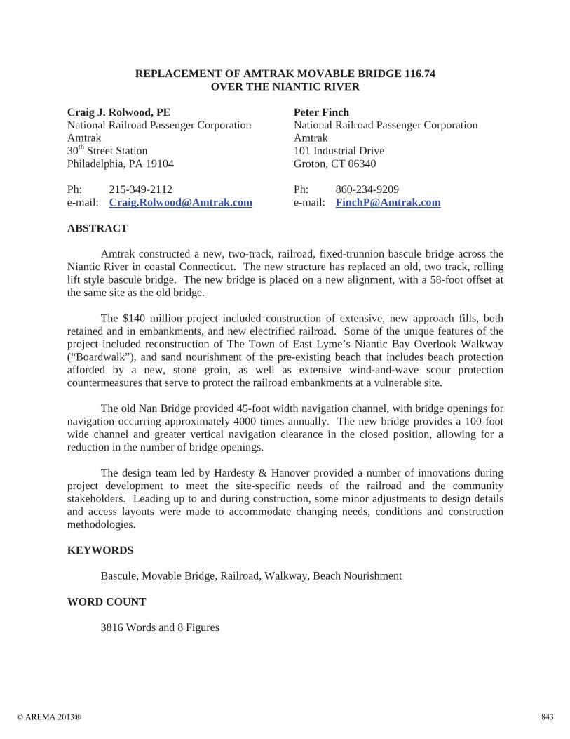
The 105-year-old “Nan Bridge” over the Niantic River between East Lyme and Waterford, New London County, CT, was removed from service on Saturday morning, September 8 2012,and replaced with a new movable bridge on new alignment next to the old bridge. Replacement of the Niantic Bridge is the culmination of a process that formally began around the year 2000, yet has been envisioned since the 1970s during the Northeast Corridor Improvement Program of Amtrak’s early years of existence. The project was completed in mid 2013.
PROJECT OVERVIEW
The new Niantic River Bridge is a 2-track, electrified bascule railroad bridge. It replacedthe old bascule bridge that had reached the end of its serviceable life, having in recent years experienced incidents of serious mechanical breakdown and increasing maintenance needs.
The new bridge is located off-line, parallel to and 58 feet south of the old bridge alignment, towards the Niantic Bay cove of the Long Island Sound. The new bridge provides increased horizontal and vertical clearances for navigation. The horizontal clearance has beenmore than doubled from 45 feet to 100 feet, with greatly improved channel alignment. The vertical clearance in the bridge closed position has increased by over four feet, from 11.5 feet to 16 feet at Mean High Water. This now permits many small recreational craft that had previously required a bridge opening to pass beneath the new bridge without an opening. Bridge open vertical clearance is unlimited.
The entire project including approaches is nearly one mile long. The bridge is 373 feet long.
Construction began on the new bridge March of 2010. The origins of the Project date to 2000 when Amtrak conducted an environmental assessment of alternatives to replace the existing crossing. The new bridge was designed between 2004 and 2006, but the Project then stalled due to a lack of funding and due to the need to resolve a few local community concerns, described in this paper further below. The Project was able to restart in early 2010 thanks to an influx of money from the American Recovery and Reinvestment Act, which provided about half of the funding.
BRIDGE TYPE SELECTION
The bridge type was originally determined during the NEPA environmental process. A bascule style movable bridge was selected to replicate the style of the old bridge. An additional benefit for this site is economics: the bascule span is generally more economical for narrower
Figure 1 The New Niantic River Bridge and the Old Bridge, Approximately One Month before Opening for Service
© AREMA 2013®844

navigation channels and higher required clearances, whereas a vertical lift style bridge is generally more economical for wider channels and lower vertical underclearance requirements.
As to the exact type of bascule bridge, during the detailed design process the design team first considered the rolling lift style of bridge, also known as the Scherzer Bascule, named after the original patent holder of the bridge style developed in the early 1900s. Many Scherzer Bascule bridges are in successful service throughout North America and in other areas of the world, and many of these bridges serve railroads. This style of bridge, which operates by rolling on a large radius, heavy steel segmental girder with heavy rolling tread and track, is often selected for replacement bridges to the present day. With current day design criteria that focus on robust, long term service, this style bridge offers a number of advantages.
At the Niantic location, a fixed trunnion style of bridge was selected. One major driver of this decision was the operational and maintenance simplification this style provides on an electrified, overhead catenary system railroad. The fixed trunnion style arrangement chosen eliminated the need for a Movable Catenary Unit(MCU). An MCU had been used on the oldbridge since the line was electrified in 2001. The “Old Nan” Movable Catenary Unit (MCU) was a rolling gantry that moved the electrification facilities out of the way of the opening bascule span. The MCU periodically failed in a partially opened position. Eliminating the need for an MCU provides some significant advantages as follows:
reduced the cost of construction;eliminated a potential failure mode,
andreduced the amount of operating time required to open or close the bridge by approximately one minute in each direction of operation.
Due to site constraints, a fixed-trunnion-style bascule bridge was viable only if the movable structure used a smaller counterweight than the steel and concrete counterweight used by the old bridge. The solution was to design a steel counterweight box filled with encapsulated lead, a very high density material. The counterweight boxes swing radii are outside of the west approach span, avoiding interference with the Overhead Catenary System (OCS).
One more design feature was required to eliminate the need for an MCU. On older style bridges of typical design, extensive overhead bracing of the back, counterweight end of the bascule span is used to provide the necessary span rigidity and stability. This bracing, during opening, would interfere with fixed-position overhead electrification wires and supports during bridge opening. For the new Niantic Bridge a double-web, steel box was used for the back, counterweight end of the girders, providing the structural stability needed without having
Figure 2 The Old Niantic Bridge in 2004. Note the Large Segmental Girder on whichthe Bridge Rolls Back During Opening. Note the Movable Catenary Unit (MCU) of the Rail Electrification at the Left
© AREMA 2013® 845

interfering bracing. The box section is transitioned to a single web girder design for the forward leaf. The box also provided containment for counterweight materials.
In summary, the overhead electric system design for the joint at the back end of the bascule span was therefore greatly simplified: a passive transition joint could be used instead of the massive machinery of a Movable Catenary Unit.
MECHANICAL AND ELECTRICAL FEATURES
The new bridge makes use of a time-tested, proven movable bridge design layout while applying modern, improved materials and systems. Machinery components are generally placed within housings and weather-proof enclosures. Bridge operating controls use redundant, relay-based logic systems with redundant, flux-vector drives. The Operator’s station is located within a new Control House next to the movable span, above the navigation channel. Critical elements and components subject to heavy rail equipment impacts were designed with extra consideration for long term serviceability.
Simplicity of design for construction, maintenance and operations was sought. The old Nan Bridge opened by a maintenance-intensive, failure-prone sprocket and chain drive system, with the motors and gears located in cramped spaces barely accessible from the tracks, requiring track foul time to access. The new bridge machinery is located in an accessible enclosure beneath the bridge at the heel approach span, and consists simply of two electric motors; brakes; two large reducers; with shafting, bearings and couplings that lead to a pinion on each side of the bridge that drives the curved rack attached to the girder.
Power source redundancy is provided. The main source of electric power comes from a utility feed through a transformer on the west side of the river in the Town of East Lyme. The bridge can also be electrically powered from the east side of the river in the Township of Waterford, and completely separate, electric power feeds have been incorporated into the bridge facilities. A third power source is an on-site, electric generator.
The control system also incorporates redundancy, with two independent control systems available at the bridge.
CONTROLS AND OPERATORS HOUSE
The new operator’s building is on the south (Niantic Bay) side of the bridge, whereas the old bridge building was on the north side. The new building has a sloped channel face that
Figure 3 Bridge Drive Pinion Delivered to Bridge Site
© AREMA 2013®846
architecturally matches the opening angle of the bascule span. Four floors are available for housing batteries and resistors, signals and communications, electrical bridge controls, and the Operators level at the top floor. Restroom facilities, personnel lockers and other amenities are included.
The bridge control desk is located in the Operators room. The Operators room has sloping windows facing towards the channel, the bay and upstream. View/security cameras with monitors in the Operators room are also provided to see around the sharp bends in the channel and past the upstream bridge.
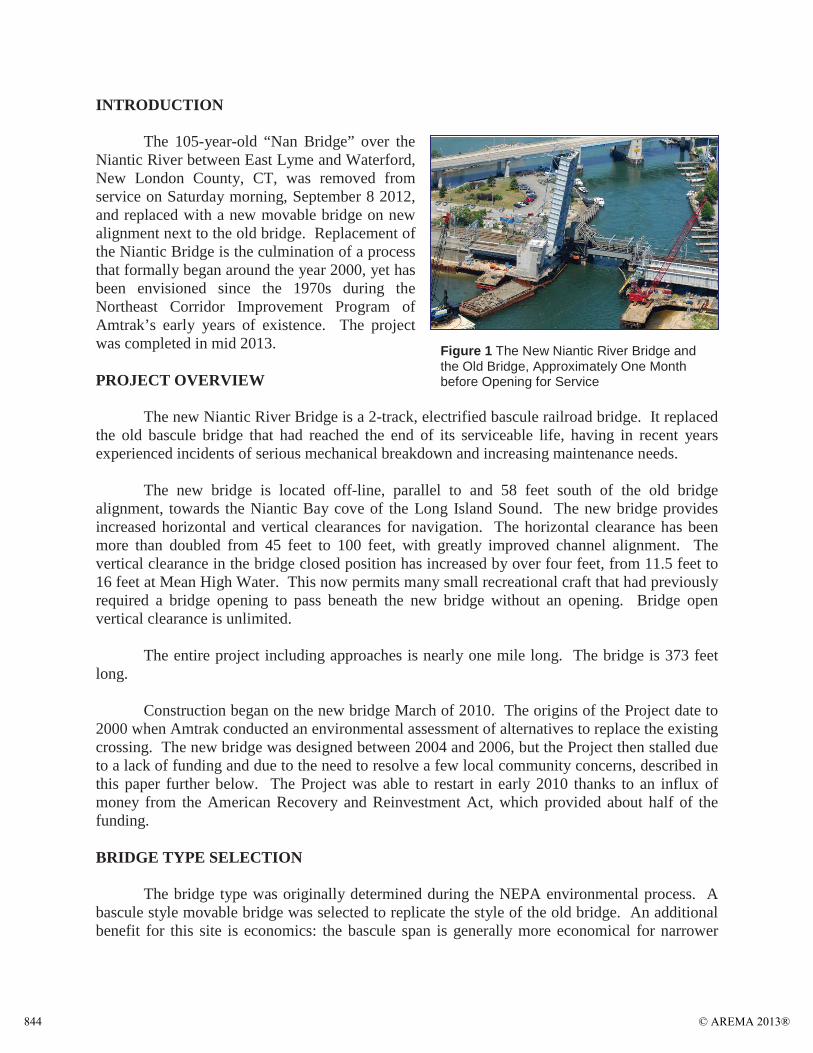
BRIDGE SUPERSTRUCTURE FRAMINGThe bascule span is a steel frame through-
girder with an open-timber deck; the bascule span is 136 feet long from trunnion to end floorbeam.The west approach span is a steel framed deck-girder with reinforced-concrete ballast pans. The longer east approach is a through-girder design. The west approach span is 91 feet and the east approach span is 126 ft.
The approach spans allow adequate underside clearances for pedestrian and emergency vehicle access. On the west side of the river in the Town of East Lyme, a 10-foot wide walkway has been designed to pass beneath the west approach next to the abutment, as part of
the Niantic Bay Overlook Walkway, a tremendously popular, passive recreational feature of the town. The pathway width and overhead clearances provided beneath the new bridge are great improvements compared to the low overhead, narrow public walkway at the old bridge.
TRACK MITER RAILS AT BASCULE SPAN JOINTS
The miter rails used on the bridge are a thick-web style, which has been developed by Amtrak for use in higher speed, passenger service on the Northeast Corridor. Because of the design layout of the bascule span, the miter rails mate passively during bridge seating, requiring no machinery or moving parts. The alignment of the miter rails at the bascule span toe is assured by a bridge span centering device located beneath the end floorbeam.
The miter rails are supported on both sides of the toe and heel open joints by oak timber mats on steel beams. The structural support conditions were designed to maintain similar track stiffness conditions on both sides of the joints, to reduce wear and pounding of the rails. Control of structural deflections of the supports beneath the miter rails is accomplished by the design of stiff floorbeams, supplemented on the toe end by live load bearings that limit the amount of floorbeam deflection that can occur during the passage of trains.
Figure 4 The Bascule Span under Construction during Night Work
© AREMA 2013® 847
BRIDGE PIERS, ABUTMENTS, AND FOUNDATIONS
The bridge substructure consists of the land based east and west abutments and in-river rest and bascule piers. The river piers are founded on spread footings constructed inside steel sheet cofferdams sealed by concrete tremie placements. The tremie bears on high bearing capacity rock or weathered rock (saprolite). Drilled shafts were considered during design, but the cofferdam and spread footing method was chosen mainly because of the cost considerations related to this particular site, and the knowledge that the nearby, Rte. 156 highway bascule bridge had been successfully constructed a few years earlier with cofferdams and spread footings on competent subsurface material.
The abutments are founded on concrete pilings. Pile capacity was confirmed using standard WEAP® and PDA® analyses. The STATNamic® method was also used to measure the pile capacity.
Reinforced concrete river pier footings, sitting on concrete tremie seals, support the bascule span. The larger Bascule Pier cofferdam footprint is 88 by 36 ft. The Rest Pier has a footprint roughly one-third the size of the Bascule Pier.
BRIDGE PIER PROTECTION
The primary reduction in risk to navigation bridge pier strikes has been accomplished by widening the navigation channel through the bridge from the restrictive 45 feet of the existing bridge, to the full upstream and downstream channel width of 100 feet.
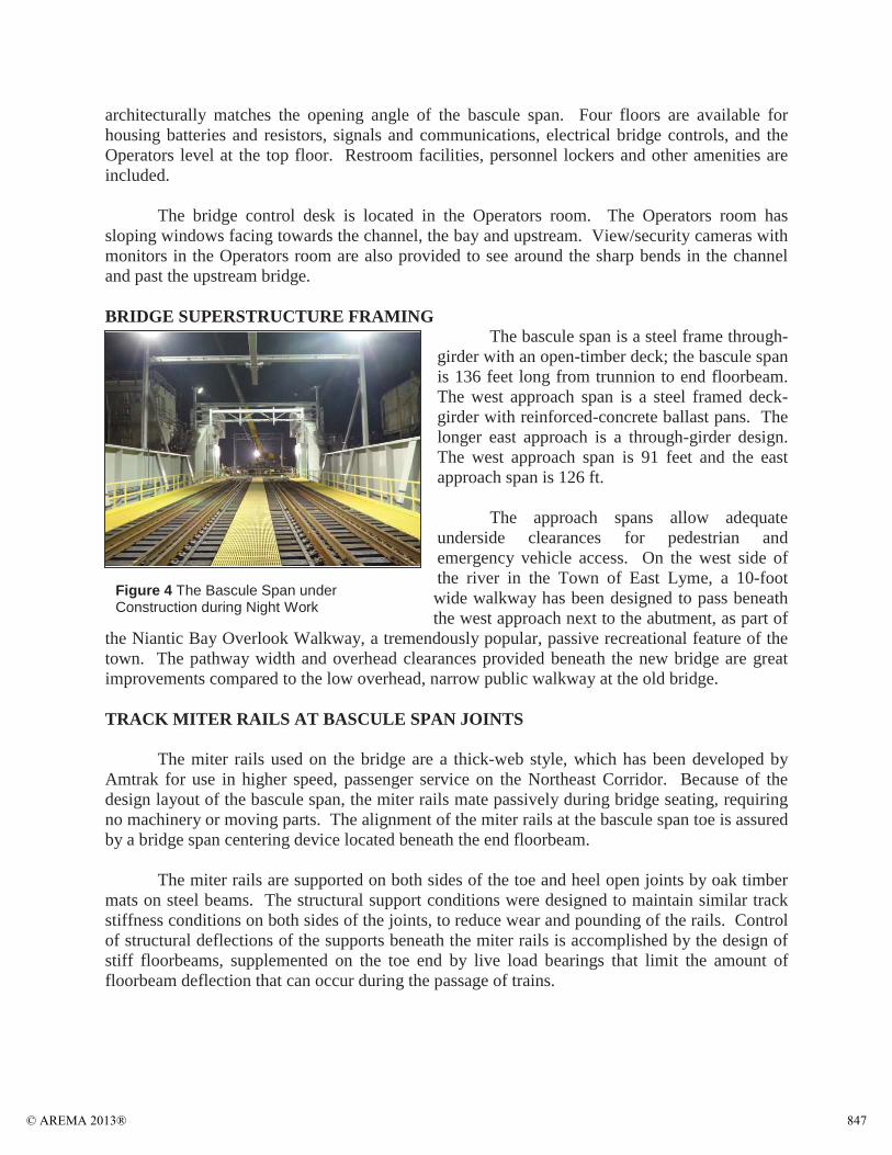
Additionally, a fender system has been constructed. The fender consists of composite plastic and fiberglass piles and plastic, dimensional lumber. The fender system has five wales with the top wale and third wale down colored safety yellow. This enhances visibility, delineates the navigable channel, protects the piers and minimizes vessel damage in the event of an allision.
CONSTRUCTION ACCESS AND STAGING
Because the bridge was constructed off-line, most of the bridge and approach construction occurred while existing rail operations were maintained unhindered. Most work could occur during normal hours away from the operating railroad; some minor operations, such as installation of “can” foundations for electric catenary poles, were performed during night time track outages.
Figure 5 Plastic Composite Fender System
© AREMA 2013®848

Site access and work area represented a significant challenge for the Contractor throughout construction.
On the west side in the Town of East Lyme, as generally anticipated by the design plans, the Contractor opted to provide a continuously manned, fenced and gated, paved construction crossing of the active tracks within the railroad signal block of the existing movable span. This allowed land transport of materials and equipment to the beach side of the project. The Contractor also made extensive use of barges and temporary support platforms along the new bridge work site. Nighttime rail delivery of materials had also been considered and included as an option in the design plans.On the east side, the Contractor made arrangements with a local property owner in Waterford to access the site through the private owner’s property. There, too, a continuously manned, fenced and gated, paved construction crossing of the active tracks within the railroad signal block of the existing movable span was provided.
Installation of the new bascule span occurred during a several day navigation channel closure in March 2012. The new bascule span steel and machinery was fabricated in Alabama. The steel of the span was assembled in the shop to assure proper fit, then disassembled and loaded in pieces on an ocean-going barge. After being shipped to Connecticut, the rear portion of the bascule span and counterweight were assembledon bascule pier supports. The forward leaf of the bascule span was reassembled on a barge. At the time of navigation channel closure, the forward leaf was floated into position, bolted to the rear portion of the bascule span, and then the entire span was rotated into the fully open position for the first time to reopen the channel to navigation. Over the ensuing months, work continued on the
structural and track portions of the bridge, and the machinery and electrical controls were completed, tested and accepted for operations.
Once the new bridge was substantially completed and ready for operations, the approach tracks were connected in a two-step process. Existing rail operation schedules were adjusted to allow single track operations on existing Track 1. The southerly, existing Track 2 and Overhead Catenary System were then aligned to the new Track 2. Single track rail service was switched from existing Track 1 to new Track 2 on Saturday morning, September 8, 2012. With the new bridge now in service, the existing bridge was taken out of service. Rail traffic was then single-tracked for about seven miles while the northerly existing Track 1 was aligned to new Track 1.
Figure 6 Bolting the Splice between the Bascule Span Rear Portion and Forward Leaf during Float-In
© AREMA 2013® 849

BRIDGE OPERATIONS
As with Old Nan, the new bridge will be kept in the open (normal) position from May 15 to October 15, closing only when trains need to cross. The bridge will open on-signal for the balance of the year. Old Nan had opened an average of between 3,800 and 4,000 times per year. It is anticipated that the added vertical clearance will reduce the number of span open requests for the new bridge, especially during the “shoulder” recreational use seasons of spring and autumn.
On average, 50 passenger trains, including local commuter trains, and two freight trains cross the bridge each day.
APPROACHES AND ENVIRONMENT
Approach fills are either on sloped berms or are retained by precast “T-Wall®” and pre-stressed concrete sheet piles. The pre-cast concrete sheet piles were set using water jetting, sinking to position under their own weight. One hundred year storm resistant rip-rap armoring was placed along the railroad, west and east side approach retaining walls along stretches vulnerable to severe wave action during storms. The expertise of coastal scientists was used to provide the design criteria and design of protective measures.
During design and for several years after design before construction began, local community concerns regarding public access and use of the narrow beach at Niantic Bay were brought to Amtrak’s attention. The local permitting approval processes became complicated by several changes over the years in the leadership of the communities and the needs of the stakeholders surrounding the construction site. Of major local concern was the disposition of the Town of East Lyme’s Niantic Bay Overlook Linear Park (“Boardwalk”) and the remaining beach after construction of the railroad on new alignment. To accommodate local concerns, the Project ultimately included the design and construction of a robust, beachfront concrete public walkway to replace a pre-existing, timber-pile supported boardwalk that was demolished during construction to allow for the new rail alignment. The walkway is within the protection of the outer cantilever retaining wall and scour protection for its entire length. At the east end of the walkway, a concrete ramp connects the walkway to a new 10-foot sidewalk. The sidewalk goes around the west bridge abutment, under the bridge, and connects to the existing parking area at the municipality’s Cini Park. Also, as part of the Project, the beach at Niantic Bay has been nourished with sand to increase its width; and a new, 200-foot long stone terminal groin (jetty) has been constructed to better control beach erosion and sand transport into the navigation channel south of the bridge. During the passage of hurricane Sandy in October 2012,
Figure 7 The New Overlook Walkway and Beach in East Lyme
© AREMA 2013®850

much of the beach nourishment sand was smoothly spread along the extended beach, and sand was pushed up against the retaining wall and into the interstices of the protective rip-rap, providing a natural grading service that could not be replicated by heavy machinery.
Environmental protections during construction included transplanting, maintaining and replanting a Connecticut Threatened and Endangered Species plant, the Seabeach Sandwort.
Open work in the waterway was environmentally restricted to seasons when fish and shellfish regeneration processes would not be affected.
A large component of construction environmental protections involved limiting construction impacts to the surrounding small-town commercial and residential areas. One way in which impacts were mitigated was to provide delivery of bulk materials by barge to greatly lessen the number of trucks passing through the nearby communities.
CONCLUSIONS
The new Niantic Railroad Bascule Bridge with approaches is now in service, with project completion in mid 2013. This replacement project was conceived in the 1970s with formal work begun around 2000.
During design, one of the greatest technical challenges was the full and efficient coordination of the bridge structural, mechanical and electrical systems and the railroad electric power traction and signals systems within a tight project site. One of the greatest management challenges for designing the bridge and its approaches was the permitting process that included several years of working with multiple administrations of the local community to satisfy the needs and desires of that community to preserve and enhance its valuable and popular beach and boardwalk area, which stretches for a half mile along the west section of the project.
For construction, there were many challenges, but one of the greatest was accessing the site for construction of the bridge and for handling the massive amounts of fill materials required to construct approach fills, to armor the beachfront with scour protection against wave action, to construct a new groin and to nourish the beach with imported sand for the benefit of the community.
This project brings advantages to the railroad, the navigation users, and the local communities adjacent to the bridge.
For the local communities:The Town of East Lyme’s Niantic Bay Overlook Linear Park (“Boardwalk”) was replaced with wider, more storm-resistant construction;A 200 foot long terminal groin has been constructed, and the adjacent beach has been replenished, providing an enhanced beach area with better control of the rate of beach erosion; and,A new, quieter bridge has replaced the older, noisier bridge.
© AREMA 2013® 851

For the navigation users:Increased vertical clearances under the bridge mean that more boats can pass without a bridge opening;Increased horizontal clearance of the navigation channel at the bridge means safer passage and passing ability of opposed marine traffic; and,Fewer waterway obstructions reduces the tidal change water velocities through the narrow Niantic channel.
For the railroad:Brand new facilities, in a state of good repair, ready for long term, reliable service;Faster train speeds are realized over the new bridge;Speedier bascule span opening and closing times;Reduced maintenance; and,Increased reliability.
The National Railroad Passenger Corporation (Amtrak) is the Owner and primary operator over the Niantic River Bridge. Designer of record and prime consultant is Hardesty & Hanover, LLC of New York City. Design sub-consultants include Gannett Fleming Transit and Rail Systems of Audubon, PA, and Diversified Technology Consultants of North Haven, CT. The Contractor is a joint venture of two established New England contractors, Cianbro-Middlesex Joint Venture. Construction Manager is URS Corporation of Rocky Hill, CT.
Figure 8 August 25, 2012 Two weeks before Placing the New Bridgein Service
© AREMA 2013®852

FIGURES LISTING
Figure 1 The New Niantic River Bridge and the Old Bridge, Approximately One Month before Opening for Service
Figure 2 The Old Niantic Bridge in 2004. Note the Large Segmental Girder on which the Bridge Rolls Back During Opening. Note the Movable Catenary Unit (MCU) of the Rail Electrification at the Left
Figure 3 Bridge Drive Pinion Delivered to Bridge SiteFigure 4 The Bascule Span under Construction during Night WorkFigure 5 Plastic Composite Fender SystemFigure 6 Bolting the Splice between the Bascule Span Rear Portion and Forward Leaf during
Float-InFigure 7 The New Overlook Walkway and Beach in East LymeFigure 8 August 25, 2012 Two weeks before Placing the New Bridge in Service
© AREMA 2013® 853

Sept
embe
r 29
–O
ctob
er 2
, 20
13In
dian
apol
is,
IN
Amtr
ak’s
Nia
ntic
Riv
er
Mov
able
Bri
dge
Repl
acem
ent
1
© AREMA 2013®854

September 29 – October 2, 2013Indianapolis, IN
Presentation Outline
2
PPPPPPPPrrrrrrrrrrrreeeeeeeeeeessssssseeeeeeeeennnnnnnnnntttttttttttttaaaaaaaaaaaaaattttttttiooooooooooooooooooooooooooooooooooooooooonnnnnnnnnnnnnnnnnn OOOOOOOOOOOOOOOuuuuuuuuuuuttttttttttttlllllllllllllliiiiiiiiiiiiiiiinnnnnnnnnnnnneeeeeeeeeee
Introduction and Design ConsiderationsCraig Rolwood
Construction and LogisticsPeter Finch
Summary: Project BenefitsCraig Rolwood
September 29 – October 2, 2013Indianapolis, IN
Location
3
U.S. Naval SubmarineBase Groton
I-95
US Coast GuardAcademy
Groton
New LondonThames
River Bridge
I-95
September 29 – October 2, 2013Indianapolis, IN
DESIGN
4
Niantic River Bridge Replacement
September 29 – October 2, 2013Indianapolis, IN
Bascule Span Replacement
5
New: Trunnion Bascule providing 100-ftChannel Clearance
Old: Rolling Lift providing 45-ft Channel Clearance
September 29 – October 2, 2013Indianapolis, IN
Design Feature: Eliminate MCU
6
Movable Catenary Unit:• Takes Time to Operate• Maintenance Required• Potential Failure Source
Old Bridge Lift Span
MCU
September 29 – October 2, 2013Indianapolis, IN
Design Feature: Eliminate MCU
7
Fixed Trunnion Style Allows Passive Catenary Break
Encapsulated Lead Counterweight
Structural Box vs. Bracing
Trunnion
Catenary Break
© AREMA 2013® 855

September 29 – October 2, 2013Indianapolis, IN
Design Feature: Miter Rails
8
Thick Web Style Miter Rail Developed by Amtrak
September 29 – October 2, 2013Indianapolis, IN
Design Feature: Miter Rails
9
Goal: Reduce “Pounding” by Controlling Miter Rail Support DeflectionsProvide Stiff End Supports
Match Cross Joint Support Stiffness (Track Modulus)
Timber Mat on Steel Stringer
Timber Mat on Steel Stringer
Bridge Joint Miter Rail
September 29 – October 2, 2013Indianapolis, IN
Design Feature: Miter Rails
10
Supplemental Live Load Deflection Control Bearings
Tiny Gap
September 29 – October 2, 2013Indianapolis, IN
Design Feature: Machinery Design
11
Simple Machinery, Accessible below Tracks in Weatherproof Enclosure
September 29 – October 2, 2013Indianapolis, IN
Design Feature: Operational Redundancy
12
Goal: Reliability, Reduce Passenger DelaysTwo Main Power Feeds, East Lyme and Waterford
Auxiliary Generator on East Lyme Side
September 29 – October 2, 2013Indianapolis, IN
Design Feature: Operational Redundancy
13
Mechanical Capability to Operate Span Half-Speed on One Reducer
Independent “A” and “B” Electrical Controls
“All Else Fails” Emergency Drive (One Hour Operation)
© AREMA 2013®856

September 29 – October 2, 2013Indianapolis, IN
Design Feature: Span Jacking
14
Jacking Capability of Full Loaded Bascule Span
September 29 – October 2, 2013Indianapolis, IN
Niantic River Bridge Replacement
CONSTRUCTION
15
September 29 – October 2, 2013Indianapolis, IN
Demolish 19th CenturySwing Bridge Foundations
16September 29 – October 2, 2013
Indianapolis, IN
New Substructure Cofferdams
17
September 29 – October 2, 2013Indianapolis, IN
New Substructure Cofferdams
18September 29 – October 2, 2013
Indianapolis, IN
Substructure Construction – Bascule Pier
19© AREMA 2013® 857

September 29 – October 2, 2013Indianapolis, IN
Substructure Construction – Bascule Pier
20September 29 – October 2, 2013
Indianapolis, IN
Abutment Construction18” Concrete Piles & STATNamic® Test
21
September 29 – October 2, 2013Indianapolis, IN
Concrete Sheetpile Retaining Wall
22September 29 – October 2, 2013
Indianapolis, IN
Concrete Sheetpile Retaining Wall
23
September 29 – October 2, 2013Indianapolis, IN
Sheetpile Retaining Walls – Removal of Obstructions
24September 29 – October 2, 2013
Indianapolis, IN25
Bascule Span Fabrication – G&G Steel in AL
© AREMA 2013®858

September 29 – October 2, 2013Indianapolis, IN
Bascule Span Fabrication – G&G Steel in AL
26September 29 – October 2, 2013
Indianapolis, IN
Approach Span Fabrication – Structal in NH
27
September 29 – October 2, 2013Indianapolis, IN
Bearing Fabrication – R. J. Watson - Buffalo
28September 29 – October 2, 2013
Indianapolis, IN
Gear Reducers – OCG - Chicago
29
September 29 – October 2, 2013Indianapolis, IN
Catenary Poles and Miscellaneous Steel Fabrication – Cianbro ME
30September 29 – October 2, 2013
Indianapolis, IN
Setting Bascule Heel Sections
31© AREMA 2013® 859

September 29 – October 2, 2013Indianapolis, IN
Assembling Bascule Span Toe Section
32September 29 – October 2, 2013
Indianapolis, IN
Float-In of Bascule Toe Section
33
September 29 – October 2, 2013Indianapolis, IN
Bascule Span – Heel to Toe Connection
34September 29 – October 2, 2013
Indianapolis, IN
Bascule Span – Startup and Testing
35
September 29 – October 2, 2013Indianapolis, IN
Rack and Pinion - Span Motor
36September 29 – October 2, 2013
Indianapolis, IN
Span Closed – Control Panel
37© AREMA 2013®860

September 29 – October 2, 2013Indianapolis, IN
Track and Electrification
38
Construction New Track #1
Installation of Cantilever and Registration Arms
September 29 – October 2, 2013Indianapolis, IN
Fender System
39
Plastic Composite, Fiber Reinforced Materials. High Ductility, High Energy Absorbing Capability.
September 29 – October 2, 2013Indianapolis, IN
Demolish “Old NAN” Bridge
40
NANCirca 1940
September 29 – October 2, 2013Indianapolis, IN
Niantic River Bridge Replacement
PROJECT BENEFITS
41
September 29 – October 2, 2013Indianapolis, IN
Project Benefit: Channel Widening
42
Navigation Channel Widened from 45 to 100-ft
September 29 – October 2, 2013Indianapolis, IN
Project Benefit: Increased Clearance
43
Navigation Vertical Clearance with Bridge Closed Increased from 11.5-ft to 16-ft at MHW
© AREMA 2013® 861

September 29 – October 2, 2013Indianapolis, IN
Niantic Bay Overlook Walkway
44
Cini Park
Goat Path West
On-Grade Stone Dust
2800 Feet (1/2 mile)
Goat Path East
On-Grade Dirt and Concrete 650 Feet
Elevated Boardwalk
1860 Feet (1/3 mile)
East Lyme
Bridge
Pre-Construction Walkway and Beach
September 29 – October 2, 2013Indianapolis, IN
Project Benefit: Concrete Walkway
45
Robust Construction Behind Storm Protection
Textured T-Wall® Along New Sidewalk
September 29 – October 2, 2013Indianapolis, IN
Project Benefit: Beach Improvements
46
SandNourishment
September 29 – October 2, 2013Indianapolis, IN
Project Benefit: Beach Improvements
47
Sand Nourishment with Erosion Transport Control (Terminal Groin)
Stone Groin
September 29 – October 2, 2013Indianapolis, IN
Project Benefit: New, Reliable Facility
48© AREMA 2013®862