Embed Size (px)
Citation preview

#9 ANCHOR-LOCK FORMING SYSTEM
90 SOUTH FOX STREET, DENVER, COLORADO (303) 744-6185 1(800) 333-8382E-MAIL: [email protected] www.gatesconcreteforms.com
®
GATES Lift’N Lock Safety Platformprovides a safe working surface[for workers only, not designedfor material or tool storage]when used with GATES #9Anchor-Lock system. Gang formand safety platform should belifted together. A weightedtongue moves back out of pocketand automatically enters pocketabove (see below). The GATESLift’N Lock Platform may be usedto brace gang forms whenproperly constructed with L.V.L.beams and a sturdy plywooddeck securely bolted together.(Not advised if high-windconditions should occur.)
(Copyrighted)
#9 A/L HEAVY DUTY FORMING SYSTEMThe GATES #9 Anchor-Lock System uses 3/4" plywood with the 4 x 4 walers on 12" centers,
crossed by additional 4 x 4 double strongbacks on 36" centers to minimize theunsupported span. GATES #9 Anchor-Locks are spaced 3'-0" x 3'-0" (9 sq. ft. max per tie).
Patented
Maximum Load per Bracket2250 Lbs. (SF = 4.1)
To include form weight, platformdead load and minimum 25 Psf
platform live load.
See GATES Lift’N Lock Platformliterature for details on properuse. Contact Gates & Sons, Inc.for help designing Lift’N LockPlatforms.
FORMING
SYSTEM
#9 ANCHOR-LOCK
Lift’N LockBracket
�Lift’N LockPocket(Cast into concrete)
�
�GATES Taper Tie(Plated, very smooth)
GATES #9 Anchor-Lock(Open & close withcarpenters hammer)
�
Advantages of Gang Forming:- Lower construction costs- No loose hardware- Gang form both sides- Pass-thru form ties
600 #9 ANCHOR-LOCK SYSTEMCOPYRIGHT 1984 - GATES & SONS, INC.PRINTED IN USAUPDATED 01/2004

112
®
CONCRETE FORMING SYSTEMS
#9 ANCHOR-LOCK GANG FORMING
The GATES Heavy-Duty #9
Anchor-Lock gang form system is in aclass by itself:
1) Provides 3'-0" x 3'-0" tie spacing.
2) Uses horizontal 4 x 4 walers, double 4 x 4vertical strongbacks and 3/4" BB Gradeor plastic-faced plywood…no expensivesteel or aluminum backup members.
3) 3/4" Plywood provides added insulationto the concrete, summer or winter.
4) Easy to job-build with carpenter labor.
5) Easy to add or modify on the job.
6) Light in weight…8-10 lbs./ sq. ft.
GATES #9 ANCHOR-LOCKBASEPLATE Vertical andhorizontal slots in baseplate providefor easy tie alignment
Strongback and tie spacings can be adjusted to fit job requirements, but never shoulda lock and tie support more than 9 sq. ft. of form. By spacing the Anchor-Locks 3'-0"along the vertical strongbacks, a tie pattern of approximately 3'-0" x 3'-0" is obtained.Multiple holes in the face of the Anchor-Lock plate allow for easy lock alignment overthe tie holes with the lag screws.
Pick-Up Loop
3/4" Form ply
#9Anchor-Lock
Tie end providesfor 1/2" inner tieset back fromface of concrete
Horizontal4 x 4son 12" centers
Vertical pairsof 4 x 4s at3'-0" O.C.
GATES PICK-UP LOOP GANG SECTION
This drawing shows a typical use.Every job needs to be designed for itsspecific use and jobsite conditions.
�
OPEN ELEVATOR / STAIR SHAFT
4 X 4Horizontalwaler
2" x 2" Angleeach end toattach gangstogether.
Pick-uppoint
Double 4 x 4strongbacks3/4"
PlywoodPick-uppoint
#9 Anchor-Lock (typ)
GATES #9 ANCHOR-LOCK GANG FORM(3'-0" x 3'-0" Tie Spacing, With No Loose Hardware!)
®
LIFT’N LOCK PLATFORM WITH #9 ANCHOR-LOCK
CLOSED ELEVATOR / STAIR SHAFTGATES Lift’N Lock Safety Platform provides a safe working surface [for workers only, not designed for material or tool storage]when used with GATES #9 Anchor-Lock system. Gang form and safety platform should be lifted together. A weightedtongue moves back out of pocket and automatically enters pocket above (see below). The GATES Lift’N Lock Platform maybe used to brace gang forms when properly constructed with L.V.L. beams and a sturdy plywood deck securely bolted together.(Not advised if high-wind conditions should occur.)
Platform LOCKED in place:Latch rotates into pocket at next work level.Bearing plate (built into pocket) distributesload to concrete.Before platform is released from crane, allsafety bolts must be in place.Form pushing devices to align form.
Platform in LIFT position:- Remove safety bolts before raising platform.- Platform is chained to bottom of gang form and
trails the collapsed form as it is lifted.- Latch rotates back into bracket as platform
is lifted, and back into pocket at next work level.Thru-boltPlatform hangs frombottom of form.
Truss hangers(by contractor)
Lift’N Lock Bracket
Lift’N LockPocket (Cast into concrete) COPYRIGHTED 1-2001
BY GATES & SONS, INC.
See GATES Lift’N Lock Platformliterature for details on properuse. Contact Gates & Sons, Inc.for help designing Lift’N LockPlatforms.
Maximum Load per Bracket2250 Lbs. (SF = 4.1)
To include form weight, platformdead load and minimum 25 Psf
platform live load.
SAFETYREQUIREMENT:
You must add crossbolts above the Pick-UpLoop bolt as a safetyprecaution.
Four (4)safety boltconnections.
A secondary strap fromthe bottom of the Pick-Up Loop down with oneadditional bottom boltmust be used.
Designed working loadnot to exceed 2000 lbs.with a four-to-one safetyfactor.
10 3
- The 2" x 3" radius steel rail is perforated with 7/16" holes for 3/8" bolts or 3/8" lag screws on 1" centers.
- The radius rails may be bolted to the form with 3/8" x 8" flat head bolts (through face of plywood) or maybe lagged to the vertical 4 x 4s on the back side of the form with 3/8" x 6-1/2" lag screws.
- The GATES #9 Side-Lock is attached to the box rail on approximately 3’-0" centers and is designed toprovide a 1/2" movement along the rail for easy alignment of form ties.
- Tie spacing should always be held to about 3’ x 3’ so that you never exceed more than 9 sq. ft. per tie.
Plywood Bending Table__________________________20'-0" Dia. 3 pcs. 1/4"30'-0" Dia. 2 pcs. 3/8"40'-0" Dia. 2 pcs. 3/8"50'-0" Dia. 1 pc. 5/8"60'-0" Dia. 1 pc. 3/4"
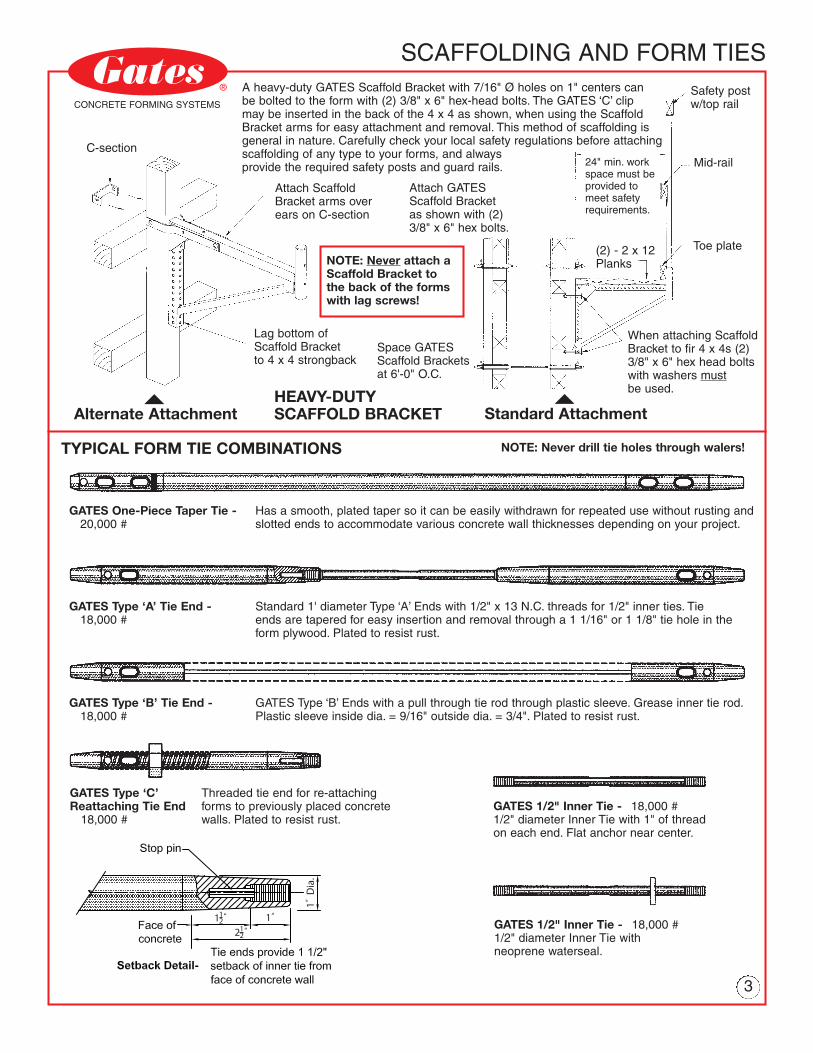
And LargerTYPICAL FORM TIE COMBINATIONS NOTE: Never drill tie holes through walers!
GATES One-Piece Taper Tie - Has a smooth, plated taper so it can be easily withdrawn for repeated use without rusting and20,000 # slotted ends to accommodate various concrete wall thicknesses depending on your project.
GATES Type ‘A’ Tie End - Standard 1' diameter Type ‘A’ Ends with 1/2" x 13 N.C. threads for 1/2" inner ties. Tie18,000 # ends are tapered for easy insertion and removal through a 1 1/16" or 1 1/8" tie hole in the
form plywood. Plated to resist rust.
GATES Type ‘B’ Tie End - GATES Type ‘B’ Ends with a pull through tie rod through plastic sleeve. Grease inner tie rod.18,000 # Plastic sleeve inside dia. = 9/16" outside dia. = 3/4". Plated to resist rust.
GATES Type ‘C’ Threaded tie end for re-attachingReattaching Tie End forms to previously placed concrete
18,000 # walls. Plated to resist rust.GATES 1/2" Inner Tie - 18,000 #1/2" diameter Inner Tie with 1" of threadon each end. Flat anchor near center.
GATES 1/2" Inner Tie - 18,000 #1/2" diameter Inner Tie withneoprene waterseal.Tie ends provide 1 1/2"
Setback Detail - setback of inner tie fromface of concrete wall.
Face ofconcrete
Stop pin
A heavy-duty GATES Scaffold Bracket with 7/16" Ø holes on 1" centers canbe bolted to the form with (2) 3/8" x 6" hex-head bolts. The GATES ‘C’ clipmay be inserted in the back of the 4 x 4 as shown, when using the ScaffoldBracket arms for easy attachment and removal. This method of scaffolding isgeneral in nature. Carefully check your local safety regulations before attachingscaffolding of any type to your forms, and alwaysprovide the required safety posts and guard rails. Mid-rail
Toe plate
When attaching ScaffoldBracket to fir 4 x 4s (2)3/8" x 6" hex head boltswith washers mustbe used.
Standard Attachment�
(2) - 2 x 12Planks
24" min. workspace must beprovided tomeet safetyrequirements.
Space GATESScaffold Bracketsat 6'-0" O.C.
HEAVY-DUTYSCAFFOLD BRACKET
Lag bottom ofScaffold Bracketto 4 x 4 strongback
NOTE: Never attach aScaffold Bracket tothe back of the formswith lag screws!
Attach GATESScaffold Bracketas shown with (2)3/8" x 6" hex bolts.
Attach ScaffoldBracket arms overears on C-section
C-section
Alternate Attachment�
SCAFFOLDING AND FORM TIES®
CONCRETE FORMING SYSTEMSSafety postw/top rail
RADIUS WALL FORMING
PLAN VIEW - TYPICAL RADIUSCENTER PLYWOOD CONNECTION PLAN VIEW - TYPICAL RADIUS GANG END
Place 4 x 4 vertical waler over joint inplywood. Attach plywood to 4 x 4 withnails or drywall screws.
Each end of radius steel walermust be securely fastened as closeto end of gang form as possible.
Use vertical 4 x 4s with 2" x 3"rolled radius walers from GATES.
GATES ADJUSTABLE RADIUS WALL GANG FORMS
GATES radius #9Side-Lock formsproduce a smoothcurved surface.
Additional rolled2" x 3" walersshould be addedwhen radius is lessthan 30'-0"
GATES #9Side-Lock
2" x 2" x 3/16"Angle bolted toend of form
GATES adjustable2" x 3" rolled radiussteel walers spaced3'-0" - 4'-0" apart
Vertical 4 x 4son 12" centers
��
GATES Adjuster
Adjustable points maybe added to each radiusrail at several points tochange radius.
Contact GATES for theproper form design on yournext radius wall project.�
®
Dia.
0
�
USE OF GATES ‘U’ CLAMP TOCONNECT FORMS
TUBE STRONGBACK FORMS AND ATTACHMENT
#9 SIDE LOCKS WITH VERTICAL4 x 4s AND PERFORATED BOX TUBE-2" x 3" Perforated steel box tube with the GATES #9Side Lock attached provides a strong form withoutloose hardware. For easy tie insertion, the Side Lockis designed for 3/4" movement along the boxrail over each tie location.
The vertical tubing may be attached with 3/8" x 6-1/2"lag bolts or 3/8" x 8" flat head bolts from the face sideof the form. Plywood should be attached to thehorizontal 4 x 4 walers with lathers drive screws, ringshank nails or galvanized nails.
Pick-up Loop attaches withtwo 3/8" x 3-1/2" machinebolts and lock nuts.
Attach box tube to walerswith 3/8" x 6 1/2" lag bolt.Pull out strength of 3/8" lagfrom fir = 800 lbs. per inchof penetration.
SECTION
VERTICAL BOX TUBE STRONGBACK WITH GATES #9SIDE-LOCKS (PLATED - TUBES AND LOCKS)
‘U’ CLAMPS ARE PLATEDTO RESIST RUST4
�
GATES‘U’ Clamp
2" x 3"Angle
2" x 2"Angle
GATES ‘U’ Clamp isideal for locking anglesand outside cornerangles. Tight lockingthat is safe, secure andeasy to use.2" x 2" or 2" x 3"
Angles are boltedwith flat head boltsat each end of thegang form. Boltangles to plywoodon 12" centers -closer onoutside corners.
A 6 1/4" x 6 1/4" x 3/16" angle is attachedto the 2" x 3" x 3/16" angles bolted to theend of each gang form. ‘U’ Clamps spacedon 1'-0" centers quickly attach the twoforms to the larger outside angle, securelylocking the corner together.
��
®
CONCRETE FORMING SYSTEMS
Example…At a pour of 6'-0" per hourat 70º F, the pressure onthe forms will be 900pounds per square foot.
LIQUID HEAD is themaximum height of liquidconcrete for a given riseper hour of concrete inthe forms.
#9 ANCHOR LOCK GANG FORM SYSTEM®
CONCRETE FORMING SYSTEMS
18’-0" High 20’-0" High 22’-0" High 24’-0" High
R=
Uni
form
Ris
eof
Con
cret
ein
For
ms
inF
eet
per
Hou
r
P = Pressure of Concrete on Form in Pounds per Square Foot
NOTE:Temperatures are prevailing temperatureof Concrete Mix in ºF. Allowance is madefor temporary internal vibration withagitation of freshly poured concrete limitedto 15 minutes from the time of placement.In cold weather, always heat concrete to40 º F minimum temperature.
RATE OF POUR CHART
9
�

58
GATES HEAVY-DUTY INSIDEBREAK-AWAY CORNER
GATES FLEX-STEEL INSIDEBREAK-AWAY CORNER
USE THESE HORIZONTAL SPACINGS WITH VERTICAL SPACINGSSHOWN BELOW AT A RATE OF POUR OF 6'-0" PER HOUR AT 70º F.
1/2" Inner Tie
3/4" Plywood
5/16" x 1-1/2"Flathead bolt at6" O.C. staggered
H.D. MetalBreak-AwayCorner
#9 Anchor-Lock
Type ‘A’ Tie End(Plated)
Dbl. 4 x 4strongbacks
4 x 4 Walerat 12" O.C.‘U’
Clamps
#9 Anchor-Lock
Dbl. 4 x 4strong-backs
4 x 4Walerat 12" O.C.
4 x 4Lumber
1/8" Rabbet
Type ‘A’ Tie End(Plated)
INSIDE AND OUTSIDE CORNERS®
CONCRETE FORMING SYSTEMS
#9 ANCHOR-LOCK GANG FORM SYSTEM®
CONCRETE FORMING SYSTEMS
8’-0" Gang
12’-0" Gang
The engineered drawings on these two pages provide you withthe correct horizontal spacing of the walers and the verticalstrongbacks. Three typical widths of gang form panels, 8'-0",12'-0" and 16'-0" wide are shown to the left. Gang form heightsfrom 8'-0" to 24'-0" high are shown below.
Select the gang form width that suits your job - thenselect the gang form height closest to your concretewall height. The gang form width and the gang formheight will establish your form tie locations. Ex: An8'-0" wide gang form is best suited for your job. Thevertical strongback spacing is 1'-0" from each end andall other equal spaces are 3'-0".
A 16'-0" high gang form is closest toyour wall height. The tie spacingfrom bottom to top on a 16'-0" highgang form is 8", 2'-8", 3'-0", 3'-0",3'-0", 3'-0" and 8". Establish your tiesand locks accordingly.
8’-0" High 10’-0" High 12’-0" High 16’-0" High
16’-0" Gang
�
GATES PIN’N LOCKOUTSIDE CORNER
Tie endsremoved
Pouredconcrete
Tie end is removedbefore form is removed
INSIDE BREAK-AWAY CORNER(Top view, retracted)
GATES Pin’N LockOutside Corner- Fast acting claw- Strong connection- Allows for adjustment- No loose parts- Open and close with
a carpenters hammer- Roll pin prevents coil
rod from falling loose.
Now you can have LEAK-PROOFcorners by using GATES adjustablePin’N Lock heavy duty, outside steelcorners, with no loose parts.
GATES PIN’N LOCK(Top View)Bolt outside corner units tocorner of gangs. Position asshown in this top view.
�For elevator or stair shaft gang form use,provides 5/8" clearance on each side at all fourcorners. To retract, loosen all bolts on verticalcross bars spaced on 24" centers using a speedwrench. Rotate turnbuckles in unison, drawingforms away from new concrete walls. Lift gangforms and reset.
GATES INSIDE BREAK-AWAY CORNER

76
4 x 4 waler being setin place on template.
Pick-up loopsattached to4 x 4 as shown.(See pg. 2)
4 x 4 Doublestrongbackin place.
4 x 4 Strongbacks are placed on 36" centers 12" in from eachend. They are then crossed by horizontal 4 x 4s on 12" centersfrom top to bottom of the gang form. Tie spacing must neverexceed 9 square feet per tie.
After template is built,4 x 4 strongbacks and4 x 4 walers are cut torequired length andplaced between 4 x 4 and2 x 4 blocking as shown.
STEP #2:POSITIONING OF 4 x 4STRONGBACKS AND4 x 4 WALERS
LOW USING A GANG FORM BUILDING TEMPLATE
3'-0" x 3'-0"Tie spacing
Drill 1 1/8" tie holethrough panel for ties.
Be certain form is squarebefore fastening plywood.
After plywood is attacheduse GATES Drill Stand todrill vertical tie holes.
When all 4 x 4 walersare set in place ontemplate, place 3/4"plywood panels over4 x 4 walers and nailto walers withdrywall screws.
STEPS #3 & #4:BUILDING GANGS &DRILLING OF FORMS
When attaching 4 x 4vertical strongbacks thatwill be used for picking,attach to gang with 3/8"diameter bolt. Bolt throughpanels, walers and strongbacks.
2" x 2" x 3/16" Angle may beattached to form while still ontemplate for gang connections.Hold angles in place with a‘C’ clamp while bolting.
Hold horizontal 4 x 4back 2-1/4" from eachend of form for vertical2" x 2" connectingangles. Attach vertical2" x 2" angles back ofplywood edge 0"-1/32".Bolt angle on 12" centers.
3/4" Ply.
0"-1/32"
2" x 2"Angle
5/16" x 1 1/2"F.H. bolt
Horizontal4 x 4 waler
Double 4 x 4strongbacks
®
CONCRETE FORMING SYSTEMS
Template (Jig Table) must bebuilt square, level & sturdy tosupport gang form.
3/4" Plywood cleats or2 x 4 blocking to positionthe 4 x 4 walers.
Blocking to position4 x 4 doublestrongbacks
Nail blocking lightlyso they may bemoved in or out fordifferent lengthgang forms.
STEP #1:BUILD TEMPLATE (JIG TABLE)
The GATES Anchor-Lock gang formmay be assembled using 3/8" x 8-1/2"flat-head bolts. The bolt shouldpenetrate the face of the plywood form,the horizontal 4 x 4 waler and thevertical strongback.
3/8" x 8-1/2" F.H. Bolt
3/8" x 7-1/2" F.H. Bolt
3/8" x 6" Lag Bolt
3/8" x 5-1/2" F.H. Bolt
5/16" x 1-1/2" F.H. Bolt
3/8"Nut/Washer
5/16"Nut/Washer
TYPICAL BOLT SIZES USEDELEVATIONSECTION
�Typical gang formwith all hardwareattached.
�
FOUR STEPS TO KEEP YOUR FABRICATION COSTS®
CONCRETE FORMING SYSTEMS
PLAN VIEW
After the jig table is built,diagonal braces should beadded to keep it perfectlysquare throughout thebuilding of all gang forms.
A second method of attachingstrongbacks to the horizontalwalers is the use of a 3/8" x 6"lag screw with 3-1/2" x 3-1/2"lumber. On any member that is tobecome a pick-up point, additionalbolts or lag screws must be used.Pull-out strength of 3/8" lag is800 lbs. per inch of penetration.
Template should bebuilt high enough abovethe ground so that thecarpenters may workunder the gang totighten bolts.

58
GATES HEAVY-DUTY INSIDEBREAK-AWAY CORNER
GATES FLEX-STEEL INSIDEBREAK-AWAY CORNER
USE THESE HORIZONTAL SPACINGS WITH VERTICAL SPACINGSSHOWN BELOW AT A RATE OF POUR OF 6'-0" PER HOUR AT 70º F.
1/2" Inner Tie
3/4" Plywood
5/16" x 1-1/2"Flathead bolt at6" O.C. staggered
H.D. MetalBreak-AwayCorner
#9 Anchor-Lock
Type ‘A’ Tie End(Plated)
Dbl. 4 x 4strongbacks
4 x 4 Walerat 12" O.C.‘U’
Clamps
#9 Anchor-Lock
Dbl. 4 x 4strong-backs
4 x 4Walerat 12" O.C.
4 x 4Lumber
1/8" Rabbet
Type ‘A’ Tie End(Plated)
INSIDE AND OUTSIDE CORNERS®
CONCRETE FORMING SYSTEMS
#9 ANCHOR-LOCK GANG FORM SYSTEM®
CONCRETE FORMING SYSTEMS
8’-0" Gang
12’-0" Gang
The engineered drawings on these two pages provide you withthe correct horizontal spacing of the walers and the verticalstrongbacks. Three typical widths of gang form panels, 8'-0",12'-0" and 16'-0" wide are shown to the left. Gang form heightsfrom 8'-0" to 24'-0" high are shown below.
Select the gang form width that suits your job - thenselect the gang form height closest to your concretewall height. The gang form width and the gang formheight will establish your form tie locations. Ex: An8'-0" wide gang form is best suited for your job. Thevertical strongback spacing is 1'-0" from each end andall other equal spaces are 3'-0".
A 16'-0" high gang form is closest toyour wall height. The tie spacingfrom bottom to top on a 16'-0" highgang form is 8", 2'-8", 3'-0", 3'-0",3'-0", 3'-0" and 8". Establish your tiesand locks accordingly.
8’-0" High 10’-0" High 12’-0" High 16’-0" High
16’-0" Gang
�
GATES PIN’N LOCKOUTSIDE CORNER
Tie endsremoved
Pouredconcrete
Tie end is removedbefore form is removed
INSIDE BREAK-AWAY CORNER(Top view, retracted)
GATES Pin’N LockOutside Corner- Fast acting claw- Strong connection- Allows for adjustment- No loose parts- Open and close with
a carpenters hammer- Roll pin prevents coil
rod from falling loose.
Now you can have LEAK-PROOFcorners by using GATES adjustablePin’N Lock heavy duty, outside steelcorners, with no loose parts.
GATES PIN’N LOCK(Top View)Bolt outside corner units tocorner of gangs. Position asshown in this top view.
�For elevator or stair shaft gang form use,provides 5/8" clearance on each side at all fourcorners. To retract, loosen all bolts on verticalcross bars spaced on 24" centers using a speedwrench. Rotate turnbuckles in unison, drawingforms away from new concrete walls. Lift gangforms and reset.
GATES INSIDE BREAK-AWAY CORNER

0
�
USE OF GATES ‘U’ CLAMP TOCONNECT FORMS
TUBE STRONGBACK FORMS AND ATTACHMENT
#9 SIDE LOCKS WITH VERTICAL4 x 4s AND PERFORATED BOX TUBE-2" x 3" Perforated steel box tube with the GATES #9Side Lock attached provides a strong form withoutloose hardware. For easy tie insertion, the Side Lockis designed for 3/4" movement along the boxrail over each tie location.
The vertical tubing may be attached with 3/8" x 6-1/2"lag bolts or 3/8" x 8" flat head bolts from the face sideof the form. Plywood should be attached to thehorizontal 4 x 4 walers with lathers drive screws, ringshank nails or galvanized nails.
Pick-up Loop attaches withtwo 3/8" x 3-1/2" machinebolts and lock nuts.
Attach box tube to walerswith 3/8" x 6 1/2" lag bolt.Pull out strength of 3/8" lagfrom fir = 800 lbs. per inchof penetration.
SECTION
VERTICAL BOX TUBE STRONGBACK WITH GATES #9SIDE-LOCKS (PLATED - TUBES AND LOCKS)
‘U’ CLAMPS ARE PLATEDTO RESIST RUST4
�
GATES‘U’ Clamp
2" x 3"Angle
2" x 2"Angle
GATES ‘U’ Clamp isideal for locking anglesand outside cornerangles. Tight lockingthat is safe, secure andeasy to use.2" x 2" or 2" x 3"
Angles are boltedwith flat head boltsat each end of thegang form. Boltangles to plywoodon 12" centers -closer onoutside corners.
A 6 1/4" x 6 1/4" x 3/16" angle is attachedto the 2" x 3" x 3/16" angles bolted to theend of each gang form. ‘U’ Clamps spacedon 1'-0" centers quickly attach the twoforms to the larger outside angle, securelylocking the corner together.
��
®
CONCRETE FORMING SYSTEMS
Example…At a pour of 6'-0" per hourat 70º F, the pressure onthe forms will be 900pounds per square foot.
LIQUID HEAD is themaximum height of liquidconcrete for a given riseper hour of concrete inthe forms.
#9 ANCHOR LOCK GANG FORM SYSTEM®
CONCRETE FORMING SYSTEMS
18’-0" High 20’-0" High 22’-0" High 24’-0" High
R=
Uni
form
Ris
eof
Con
cret
ein
For
ms
inF
eet
per
Hou
r
P = Pressure of Concrete on Form in Pounds per Square Foot
NOTE:Temperatures are prevailing temperatureof Concrete Mix in ºF. Allowance is madefor temporary internal vibration withagitation of freshly poured concrete limitedto 15 minutes from the time of placement.In cold weather, always heat concrete to40 º F minimum temperature.
RATE OF POUR CHART
9
�

10 3
- The 2" x 3" radius steel rail is perforated with 7/16" holes for 3/8" bolts or 3/8" lag screws on 1" centers.
- The radius rails may be bolted to the form with 3/8" x 8" flat head bolts (through face of plywood) or maybe lagged to the vertical 4 x 4s on the back side of the form with 3/8" x 6-1/2" lag screws.
- The GATES #9 Side-Lock is attached to the box rail on approximately 3’-0" centers and is designed toprovide a 1/2" movement along the rail for easy alignment of form ties.
- Tie spacing should always be held to about 3’ x 3’ so that you never exceed more than 9 sq. ft. per tie.
Plywood Bending Table__________________________20'-0" Dia. 3 pcs. 1/4"30'-0" Dia. 2 pcs. 3/8"40'-0" Dia. 2 pcs. 3/8"50'-0" Dia. 1 pc. 5/8"60'-0" Dia. 1 pc. 3/4"
And LargerTYPICAL FORM TIE COMBINATIONS NOTE: Never drill tie holes through walers!
GATES One-Piece Taper Tie - Has a smooth, plated taper so it can be easily withdrawn for repeated use without rusting and20,000 # slotted ends to accommodate various concrete wall thicknesses depending on your project.
GATES Type ‘A’ Tie End - Standard 1' diameter Type ‘A’ Ends with 1/2" x 13 N.C. threads for 1/2" inner ties. Tie18,000 # ends are tapered for easy insertion and removal through a 1 1/16" or 1 1/8" tie hole in the
form plywood. Plated to resist rust.
GATES Type ‘B’ Tie End - GATES Type ‘B’ Ends with a pull through tie rod through plastic sleeve. Grease inner tie rod.18,000 # Plastic sleeve inside dia. = 9/16" outside dia. = 3/4". Plated to resist rust.
GATES Type ‘C’ Threaded tie end for re-attachingReattaching Tie End forms to previously placed concrete
18,000 # walls. Plated to resist rust.GATES 1/2" Inner Tie - 18,000 #1/2" diameter Inner Tie with 1" of threadon each end. Flat anchor near center.
GATES 1/2" Inner Tie - 18,000 #1/2" diameter Inner Tie withneoprene waterseal.Tie ends provide 1 1/2"
Setback Detail - setback of inner tie fromface of concrete wall.
Face ofconcrete
Stop pin
A heavy-duty GATES Scaffold Bracket with 7/16" Ø holes on 1" centers canbe bolted to the form with (2) 3/8" x 6" hex-head bolts. The GATES ‘C’ clipmay be inserted in the back of the 4 x 4 as shown, when using the ScaffoldBracket arms for easy attachment and removal. This method of scaffolding isgeneral in nature. Carefully check your local safety regulations before attachingscaffolding of any type to your forms, and alwaysprovide the required safety posts and guard rails. Mid-rail
Toe plate
When attaching ScaffoldBracket to fir 4 x 4s (2)3/8" x 6" hex head boltswith washers mustbe used.
Standard Attachment�
(2) - 2 x 12Planks
24" min. workspace must beprovided tomeet safetyrequirements.
Space GATESScaffold Bracketsat 6'-0" O.C.
HEAVY-DUTYSCAFFOLD BRACKET
Lag bottom ofScaffold Bracketto 4 x 4 strongback
NOTE: Never attach aScaffold Bracket tothe back of the formswith lag screws!
Attach GATESScaffold Bracketas shown with (2)3/8" x 6" hex bolts.
Attach ScaffoldBracket arms overears on C-section
C-section
Alternate Attachment�
SCAFFOLDING AND FORM TIES®
CONCRETE FORMING SYSTEMSSafety postw/top rail
RADIUS WALL FORMING
PLAN VIEW - TYPICAL RADIUSCENTER PLYWOOD CONNECTION PLAN VIEW - TYPICAL RADIUS GANG END
Place 4 x 4 vertical waler over joint inplywood. Attach plywood to 4 x 4 withnails or drywall screws.
Each end of radius steel walermust be securely fastened as closeto end of gang form as possible.
Use vertical 4 x 4s with 2" x 3"rolled radius walers from GATES.
GATES ADJUSTABLE RADIUS WALL GANG FORMS
GATES radius #9Side-Lock formsproduce a smoothcurved surface.
Additional rolled2" x 3" walersshould be addedwhen radius is lessthan 30'-0"
GATES #9Side-Lock
2" x 2" x 3/16"Angle bolted toend of form
GATES adjustable2" x 3" rolled radiussteel walers spaced3'-0" - 4'-0" apart
Vertical 4 x 4son 12" centers
��
GATES Adjuster
Adjustable points maybe added to each radiusrail at several points tochange radius.
Contact GATES for theproper form design on yournext radius wall project.�
®
112
®
CONCRETE FORMING SYSTEMS
#9 ANCHOR-LOCK GANG FORMING
The GATES Heavy-Duty #9
Anchor-Lock gang form system is in aclass by itself:
1) Provides 3'-0" x 3'-0" tie spacing.
2) Uses horizontal 4 x 4 walers, double 4 x 4vertical strongbacks and 3/4" BB Gradeor plastic-faced plywood…no expensivesteel or aluminum backup members.
3) 3/4" Plywood provides added insulationto the concrete, summer or winter.
4) Easy to job-build with carpenter labor.
5) Easy to add or modify on the job.
6) Light in weight…8-10 lbs./ sq. ft.
GATES #9 ANCHOR-LOCKBASEPLATE Vertical andhorizontal slots in baseplate providefor easy tie alignment
Strongback and tie spacings can be adjusted to fit job requirements, but never shoulda lock and tie support more than 9 sq. ft. of form. By spacing the Anchor-Locks 3'-0"along the vertical strongbacks, a tie pattern of approximately 3'-0" x 3'-0" is obtained.Multiple holes in the face of the Anchor-Lock plate allow for easy lock alignment overthe tie holes with the lag screws.
Pick-Up Loop
3/4" Form ply
#9Anchor-Lock
Tie end providesfor 1/2" inner tieset back fromface of concrete
Horizontal4 x 4son 12" centers
Vertical pairsof 4 x 4s at3'-0" O.C.
GATES PICK-UP LOOP GANG SECTION
This drawing shows a typical use.Every job needs to be designed for itsspecific use and jobsite conditions.
�
OPEN ELEVATOR / STAIR SHAFT
4 X 4Horizontalwaler
2" x 2" Angleeach end toattach gangstogether.
Pick-uppoint
Double 4 x 4strongbacks3/4"
PlywoodPick-uppoint
#9 Anchor-Lock (typ)
GATES #9 ANCHOR-LOCK GANG FORM(3'-0" x 3'-0" Tie Spacing, With No Loose Hardware!)
®
LIFT’N LOCK PLATFORM WITH #9 ANCHOR-LOCK
CLOSED ELEVATOR / STAIR SHAFTGATES Lift’N Lock Safety Platform provides a safe working surface [for workers only, not designed for material or tool storage]when used with GATES #9 Anchor-Lock system. Gang form and safety platform should be lifted together. A weightedtongue moves back out of pocket and automatically enters pocket above (see below). The GATES Lift’N Lock Platform maybe used to brace gang forms when properly constructed with L.V.L. beams and a sturdy plywood deck securely bolted together.(Not advised if high-wind conditions should occur.)
Platform LOCKED in place:Latch rotates into pocket at next work level.Bearing plate (built into pocket) distributesload to concrete.Before platform is released from crane, allsafety bolts must be in place.Form pushing devices to align form.
Platform in LIFT position:- Remove safety bolts before raising platform.- Platform is chained to bottom of gang form and
trails the collapsed form as it is lifted.- Latch rotates back into bracket as platform
is lifted, and back into pocket at next work level.Thru-boltPlatform hangs frombottom of form.
Truss hangers(by contractor)
Lift’N Lock Bracket
Lift’N LockPocket (Cast into concrete) COPYRIGHTED 1-2001
BY GATES & SONS, INC.
See GATES Lift’N Lock Platformliterature for details on properuse. Contact Gates & Sons, Inc.for help designing Lift’N LockPlatforms.
Maximum Load per Bracket2250 Lbs. (SF = 4.1)
To include form weight, platformdead load and minimum 25 Psf
platform live load.
SAFETYREQUIREMENT:
You must add crossbolts above the Pick-UpLoop bolt as a safetyprecaution.
Four (4)safety boltconnections.
A secondary strap fromthe bottom of the Pick-Up Loop down with oneadditional bottom boltmust be used.
Designed working loadnot to exceed 2000 lbs.with a four-to-one safetyfactor.
#9 ANCHOR-LOCK FORMING SYSTEM
90 SOUTH FOX STREET, DENVER, COLORADO (303) 744-6185 1(800) 333-8382E-MAIL: [email protected] www.gatesconcreteforms.com
®
GATES Lift’N Lock Safety Platformprovides a safe working surface[for workers only, not designedfor material or tool storage]when used with GATES #9Anchor-Lock system. Gang formand safety platform should belifted together. A weightedtongue moves back out of pocketand automatically enters pocketabove (see below). The GATESLift’N Lock Platform may be usedto brace gang forms whenproperly constructed with L.V.L.beams and a sturdy plywooddeck securely bolted together.(Not advised if high-windconditions should occur.)
(Copyrighted)
#9 A/L HEAVY DUTY FORMING SYSTEMThe GATES #9 Anchor-Lock System uses 3/4" plywood with the 4 x 4 walers on 12" centers,
crossed by additional 4 x 4 double strongbacks on 36" centers to minimize theunsupported span. GATES #9 Anchor-Locks are spaced 3'-0" x 3'-0" (9 sq. ft. max per tie).
Patented
Maximum Load per Bracket2250 Lbs. (SF = 4.1)
To include form weight, platformdead load and minimum 25 Psf
platform live load.
See GATES Lift’N Lock Platformliterature for details on properuse. Contact Gates & Sons, Inc.for help designing Lift’N LockPlatforms.
FORMING
SYSTEM
#9 ANCHOR-LOCK
Lift’N LockBracket
�Lift’N LockPocket(Cast into concrete)
�
�GATES Taper Tie(Plated, very smooth)
GATES #9 Anchor-Lock(Open & close withcarpenters hammer)
�
Advantages of Gang Forming:- Lower construction costs- No loose hardware- Gang form both sides- Pass-thru form ties
600 #9 ANCHOR-LOCK SYSTEMCOPYRIGHT 1984 - GATES & SONS, INC.PRINTED IN USAUPDATED 01/2004