Embed Size (px)
Citation preview
HD / EDData Sheet
HD Hysteresis DynamometersED Engine Dynamometers
1 www.magtrol.com
MAGTROL
HD Features• 16StandardModelswithMaximumTorquefrom
2.5oz·into500lb·in(18mN·mto56.5N·m)
• HysteresisBrakingSystem:providesprecisetorqueloadingindependentofshaftspeed
• MotorTesting:fromnoloadtolockedrotor
• StandardTorqueUnits:English,MetricandSI
• Accuracy:±0.25%to±0.5%(fullscale)
• AirFlowSensor:Forprotectionagainstoverheatingandoperatorerror
• BasePlates:availableinlongorshortversions
• CustomDynamometers:forspecialtorqueandspeedrequirements
• EasyCalibration
HD DescriptionHysteresisBrakeDynamometers(HDSeries)areversatileandidealfortestinginthelowtomediumpowerrange(maximum14kWintermittentduty).WithaHysteresisBrakingsystem,theDynamometersdonot requirespeed tocreate torque,andthereforecanprovideafullmotorrampfromfree-runtolockedrotor.Brakecoolingisprovidedbyconvection(noexternalsource),bycompressedairorbydedicatedblower,dependingonthemodel.AllMagtrolHysteresisDynamometershaveaccuracyratingsof±0.25%to±0.5%fullscale—dependingonsizeandsystemconfiguration.
Tobetterintegratedynamometersintosystems,Magtroloffers both long and short base plates. Theshorter baseplate facilitates easiermotormountingwhenusedwithT-slottablesand MagtrolAdjustable MotorFixtures,whereasthelongbaseplatesarebetter suited for tabletoptesting.
HD applicationsMagtrol motor test systems can be found in test labs, atinspectionstations,andonthemanufacturingfloorsofmostoftheworld’sleadingmanufacturers,usersandcertifiersofsmalltomediumsizedelectric,pneumaticandhydraulicmotors,as well as internal combustion engines. Magtrol suppliesmotortestsystemsforawidearrayofindustriesincluding:Appliance,Automotive,Aviation,Computer,HVAC,Lawnand Garden, Medical and Dental, Electric Motor, OfficeEquipmentandPowerTools.
eD DescriptionWith Magtrol’s Engine Dynamometers, high performance
motor testing is available to manufacturers andusers of small engines. Magtrol’sEngine Dynamometers have beendesignedtoaddressthesevere,highvibration conditions inherent ininternalcombustionenginetesting.
Magtrol’s Engine Dynamometersare highly accurate (± 0.25% of
full scale) and can be controlledeithermanuallyorviaaPCbasedController.Forasmallenginetest
stand, Magtrol offers a full line ofcontrollers,readoutsandsoftware.
AswithallMagtrolHysteresisDynamometers,engineloadingisprovidedbyMagtrol’sHysteresis
Brake,whichprovides:torqueindependentofspeed,including full load at 0 rpm; excellent repeatability;
frictionlesstorquewithnowearingparts(otherthanbearings);and long operating life with low maintenance. Magtrolprovides a NIST traceable certificate of calibration, andcalibrationbeamwitheachEngineDynamometer.
eD applicationsTheEngineDynamometersareideallysuitedforemissionstestingassetforthinCARBandEPACleanAirRegulations.TheDynamometerswilloffersuperiorperformanceon theproductionline,atincominginspectionorintheR&Dlab.
eD Features• MaximumTorque:from55lb·into250lb·in
(6.5N·mto28N·m)• HysteresisBrakingSystem• MotorTesting:fromnoloadtolockedrotor• StandardTorqueUnits:English,Metric&SIavailable• Accuracy:±0.25%(fullscale)• BlowerCooled:tomaximizeheatdissipation• AirFlowSensor:forprotectionagainstoverheating
andoperatorerror• SpeciallyReinforcedLoadCell:stainlesssteelpinat
contactpointpreventsprematurewearfromexcessvibration• LargerShaft:foradditionalstrength• GussetedPillowBlocks:foradditionalfrontandrear
support• EasyCalibration
Model HD-710Hysteresis Dynamometer
with long base plate
2 MAGTROL
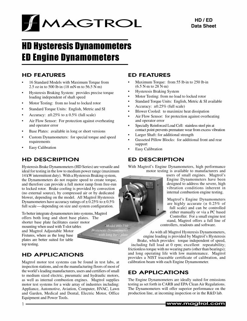
HD / EDPrinciples and Selectionoperating principles
AIR GAP
FIELD COIL
BALL BEARINGS
SHAFT
POLE STRUCTURE
HUB
ROTOR(Drag Cup)
Magtrol Hysteresis Dynamometers absorb power with auniqueHysteresisBrakingSystemwhichprovidesfrictionlesstorqueloadingindependentofshaftspeed. TheHysteresisBrakeprovidestorquebytheuseoftwobasiccomponents—areticulated pole structure and a specialty steel rotor/shaftassembly—fittedtogetherbutnotinphysicalcontact.Untilthepolestructureisenergized,thedragcupcanspinfreelyon its shaftbearings. Whenamagnetizing force from thefieldcoilisappliedtothepolestructure,theairgapbecomesafluxfieldandtherotorismagneticallyrestrained,providingabrakingactionbetweenthepolestructureandrotor.
complete pc controlMagtrol’sM-TEST7Softwareisastate-of-the-artmotortestingprogram forWindows®-baseddata acquisition. UsedwithaMagtrolProgrammableDynamometerController,MagtrolM-TEST 7 Software provides the control of any MagtrolDynamometerandrunstestsequencesinamannerbestsuitedtotheoverallaccuracyandefficiencyoftheMagtrolMotorTestSystem.ThedatathatisgeneratedbyMagtrol’sMotorTestingSoftwarecanbestored,displayedandprintedintabularorgraphicformats,andcanbeeasilyimportedintoaspreadsheet.
WritteninLabVIEW™,M-TEST7hastheflexibilitytotestamajorityofmotortypesinavarietyofways.BecauseofLabVIEW’sversatility,obtainingdatafromothersources(e.g.thermocouples),controllingmotorpowerandprovidingaudio/visualindicatorsisrelativelyeasy.
Magtrol’sM-TEST7Softwareisidealforsimulatingloads,cyclingtheunitundertestandmotorramping.Becauseitiseasytogatherdataandduplicatetests,thesoftwareisidealforuseinengineeringlabs.Testscanbeprogrammedtorunontheirownandsavedforfutureuseallowingforvaluabletimesavingsinproductiontestingandincoming/outgoinginspection.
Dynamometer selectionMagtrol’sHysteresisDynamometerscoverawiderangeofTorque,SpeedandMechanicalPowerratings.ToselecttheappropriatesizeDynamometerforyourmotortestingneeds,youwillneed todetermine theMaximum Torque, Speed and PowerappliedtotheDynamometer.
Maximum Torque
The Magtrol HysteresisAbsorption Dynamometer willdevelopbrakingtorqueatanyspeedpoint,includinglowspeedandstall conditions (“0” rpm). It is important toconsideralltorquepointsthataretobetested,notonlyratedtorque,butalsolockedrotorandbreakdowntorque.Dynamometerselectionshouldinitiallybebasedonthemaximumtorquerequirement, subject to determining the maximum powerrequirements.
Maximum Speed
This rating is to be considered independent of torque andpower requirements, and is the maximum speed at whichtheDynamometercanbesafelyrununderfree-runorlightlyloadedconditions.Itisnottobeconsideredasthemaximumspeedatwhichfullbrakingtorquecanbeapplied.
Maximum Power Ratings
These ratings represent the maximum capability of theDynamometerBrakingSystemtoabsorbanddissipateheatgeneratedwhenapplyingabrakingloadtothemotorundertest. The power absorbed and the heat generated by theDynamometerisafunctionoftheTorque(T)appliedtothemotorundertest,andtheresultingSpeed(n)of themotor.Thisisexpressedinthesepower(P)formulas:
TheDynamometer’sabilitytodissipateheatisafunctionofhowlongaloadwillbeapplied.Forthisreason,themaximumpowerratingsgivenarebasedoncontinuousoperationunderload,aswellasamaximumof5minutesunderload.
To safely dissipate heat and avoid Dynamometer failure, the maximum power rating is the most important consideration in selecting a Dynamometer.
SI: P(watts)=T(N·m)×n(rpm)×(1.047×10⁻¹)
English:P(watts)=T(lb·in)×n(rpm)×(1.183×10⁻²)
Metric: P(watts)=T(kg·cm)×n(rpm)×(1.027×10⁻²)
All of Magtrol’s controllers, readouts and software calculate horsepower as defined by 1 hp = 550 lb·ft / s. Using this definition:
hp=P(watts)/745.7
HD / ED
Magtrol offers three types of dynamometer brakes to absorb load: Hysteresis, Eddy Current and Magnetic Powder. Each type of Dynamometer has advantages and limitations and choosing the correct one will depend largely on the type of testing to be performed. With over 50 models to choose from, Magtrol Sales professionals are readily available to assist in selecting the proper Dynamometer to meet your testing needs.
3 MAGTROL
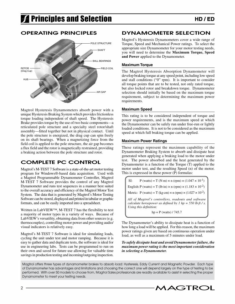
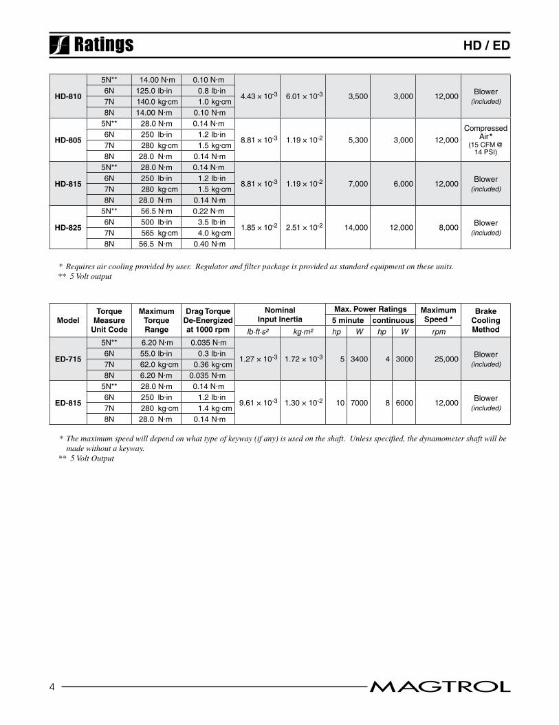
HD / EDRatings
* Requires air cooling provided by user. Regulator and filter package is provided as standard equipment on these units. ** 5 Volt output
ModelTorque
MeasureUnit Code
MaximumTorqueRange
Drag TorqueDe-Energizedat 1000 rpm
NominalInput Inertia
Max. Power Ratings MaximumSpeed
BrakeCoolingMethod
5 minute continuous
lb·ft·s² kg·m² W W rpm
HD-106
5N** 0.018 N·m 0.056 mN·m
7.04 × 10⁻⁷ 9.54 × 10⁻⁷ 35 7 30,000 Convection6N 2.50 oz·in 0.008 oz·in7N 180.0 g·cm 0.57 g·cm8N 18.00 mN·m 0.056 mN·m
HD-100
5N** 0.08 N·m 0.64 mN·m
3.40 × 10⁻⁶ 4.61 × 10⁻⁶ 75 20 25,000 Convection6N 11.00 oz·in 0.09 oz·in7N 800 g·cm 6.5 g·cm8N 80.0 mN·m 0.64 mN·m
HD-400
5N** 0.28 N·m 2 mN·m
1.55 × 10⁻⁵ 2.10 × 10⁻⁵ 200 55 25,000 Convection6N 40.0 oz·in 0.25 oz·in7N 2.80 kg·cm 0.02 kg·cm8N 280 mN·m 2 mN·m
HD-500
5N** 0.85 N·m 5 mN·m
8.05 × 10⁻⁵ 1.09 × 10⁻⁴ 400 80 25,000 Convection6N 120.0 oz·in 0.5 oz·in7N 8.50 kg·cm 0.05 kg·cm8N 850 mN·m 5 mN·m
HD-510
5N** 0.85 N·m 5 mN·m
8.05 × 10⁻⁵ 1.09 × 10⁻⁴ 750 375 25,000Compressed
Air *(7 CFM @ 1.75 PSI)
6N 120.0 oz·in 0.5 oz·in7N 8.50 kg·cm 0.05 kg·cm8N 850 mN·m 5 mN·m
HD-505
5N** 1.7 N·m 10 mN·m
1.61 × 10⁻⁴ 2.18 × 10⁻⁴ 800 160 25,000 Convection6N 240 oz·in 1.0 oz·in7N 17.00 kg·cm 0.1 kg·cm8N 1700 mN·m 10 mN·m
HD-515
5N** 1.7 N·m 10 mN·m
1.61 × 10⁻⁴ 2.18 × 10⁻⁴ 1,500 900 25,000Compressed
Air *(10 CFM @
4 PSI)
6N 240 oz·in 1.0 oz·in7N 17.00 kg·cm 0.1 kg·cm8N 1700 mN·m 10 mN·m
HD-700
5N** 3.10 N·m 0.013 N·m
5.51 × 10⁻⁴ 7.47 × 10⁻⁴ 700 150 25,000 Convection6N 440 oz·in 2.0 oz·in7N 31.0 kg·cm 0.14 kg·cm8N 3.10 N·m 0.013 N·m
HD-710
5N** 3.10 N·m 0.013 N·m
5.51 × 10⁻⁴ 7.47 × 10⁻⁴ 1,500 935 25,000 Blower (included)
6N 440 oz·in 2.0 oz·in7N 31.0 kg·cm 0.14 kg·cm8N 3.10 N·m 0.013 N·m
HD-705
5N** 6.20 N·m 0.023 N·m
1.10 × 10⁻³ 1.49 × 10⁻³ 1,400 300 25,000 Convection6N 55.0 lb·in 0.2 lb·in7N 62.0 kg·cm 0.24 kg·cm8N 6.20 N·m 0.023 N·m
HD-715
5N** 6.20 N·m 0.023 N·m
1.10 × 10⁻³ 1.49 × 10⁻³ 3,400 3,000 25,000 Blower (included)
6N 55.0 lb·in 0.2 lb·in7N 62.0 kg·cm 0.24 kg·cm8N 6.20 N·m 0.023 N·m
HD-800
5N** 14.00 N·m 0.10 N·m
4.43 × 10⁻³ 6.01 × 10⁻³ 2,800 1,800 12,000Compressed
Air *(7.5 CFM @
7 PSI)
6N 125.0 lb·in 0.8 lb·in7N 140.0 kg·cm 1.0 kg·cm8N 14.00 N·m 0.10 N·m
4 MAGTROL
HD / ED
HD-810
5N** 14.00 N·m 0.10 N·m
4.43 × 10⁻³ 6.01 × 10⁻³ 3,500 3,000 12,000 Blower (included)
6N 125.0 lb·in 0.8 lb·in7N 140.0 kg·cm 1.0 kg·cm8N 14.00 N·m 0.10 N·m
HD-805
5N** 28.0 N·m 0.14 N·m
8.81 × 10⁻³ 1.19 × 10⁻² 5,300 3,000 12,000Compressed
Air *(15 CFM @
14 PSI)
6N 250 lb·in 1.2 lb·in7N 280 kg·cm 1.5 kg·cm8N 28.0 N·m 0.14 N·m
HD-815
5N** 28.0 N·m 0.14 N·m
8.81 × 10⁻³ 1.19 × 10⁻² 7,000 6,000 12,000 Blower (included)
6N 250 lb·in 1.2 lb·in7N 280 kg·cm 1.5 kg·cm8N 28.0 N·m 0.14 N·m
HD-825
5N** 56.5 N·m 0.22 N·m
1.85 × 10⁻² 2.51 × 10⁻² 14,000 12,000 8,000 Blower (included)
6N 500 lb·in 3.5 lb·in7N 565 kg·cm 4.0 kg·cm8N 56.5 N·m 0.40 N·m
* Requires air cooling provided by user. Regulator and filter package is provided as standard equipment on these units. ** 5 Volt output
TorqueMeasure
Unit Code
MaximumTorqueRange
Drag TorqueDe-Energizedat 1000 rpm
Nominal Input Inertia
Max. Power Ratings MaximumSpeed *
BrakeCoolingMethod
Model 5 minute continuouslb·ft·s² kg·m² hp W hp W rpm
ED-715
5N** 6.20 N·m 0.035 N·m
1.27 × 10⁻³ 1.72 × 10⁻³ 5 3400 4 3000 25,000 Blower (included)
6N 55.0 lb·in 0.3 lb·in7N 62.0 kg·cm 0.36 kg·cm8N 6.20 N·m 0.035 N·m
ED-815
5N** 28.0 N·m 0.14 N·m
9.61 × 10⁻³ 1.30 × 10⁻² 10 7000 8 6000 12,000 Blower (included)
6N 250 lb·in 1.2 lb·in7N 280 kg·cm 1.4 kg·cm8N 28.0 N·m 0.14 N·m
* The maximum speed will depend on what type of keyway (if any) is used on the shaft. Unless specified, the dynamometer shaft will be made without a keyway.
** 5 Volt Output
Ratings
5 MAGTROL
HD / ED
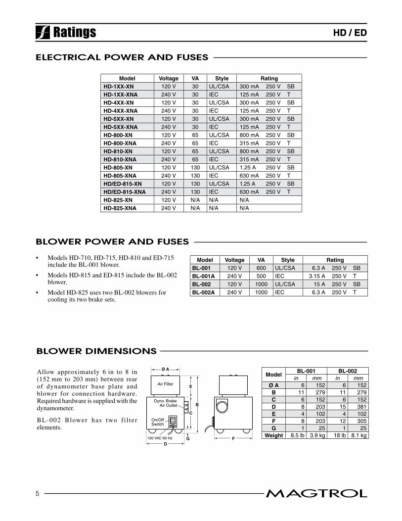
ModelBL-001 BL-002
in mm in mmØ A 6 152 6 152B 11 279 11 279C 6 152 6 152D 8 203 15 381E 4 102 4 102F 8 203 12 305G 1 25 1 25
Weight 8.5 lb 3.9 kg 18 lb 8.1 kg
Model Voltage VA Style RatingBL-001 120 V 600 UL/CSA 6.3 A 250 V SBBL-001A 240 V 500 IEC 3.15 A 250 V TBL-002 120 V 1000 UL/CSA 15 A 250 V SBBL-002A 240 V 1000 IEC 6.3 A 250 V T
Blower Dimensions
120 VAC 60 Hz
Ø A
E
C
B
DFG
Air Filter
Dyno. BrakeAir Outlet
On/OffSwitch
Allow approximately 6in to 8 in(152mm to 203mm) between rearof dynamometer base plate andblower for connection hardware.Requiredhardwareissuppliedwiththedynamometer.
BL-002 Blower has two fi l terelements.
Blower power anD Fuses
electrical power anD Fuses
Model Voltage VA Style RatingHD-1XX-XN 120 V 30 UL/CSA 300 mA 250 V SBHD-1XX-XNA 240 V 30 IEC 125 mA 250 V THD-4XX-XN 120 V 30 UL/CSA 300 mA 250 V SBHD-4XX-XNA 240 V 30 IEC 125 mA 250 V THD-5XX-XN 120 V 30 UL/CSA 300 mA 250 V SBHD-5XX-XNA 240 V 30 IEC 125 mA 250 V THD-800-XN 120 V 65 UL/CSA 800 mA 250 V SBHD-800-XNA 240 V 65 IEC 315 mA 250 V THD-810-XN 120 V 65 UL/CSA 800 mA 250 V SBHD-810-XNA 240 V 65 IEC 315 mA 250 V THD-805-XN 120 V 130 UL/CSA 1.25 A 250 V SBHD-805-XNA 240 V 130 IEC 630 mA 250 V THD/ED-815-XN 120 V 130 UL/CSA 1.25 A 250 V SBHD/ED-815-XNA 240 V 130 IEC 630 mA 250 V THD-825-XN 120 V N/A N/A N/AHD-825-XNA 240 V N/A N/A N/A
• ModelsHD-710,HD-715,HD-810andED-715includetheBL-001blower.
• ModelsHD-815andED-815includetheBL-002blower.
• ModelHD-825usestwoBL-002blowersforcoolingitstwobrakesets.
Ratings HD / ED
6 MAGTROL
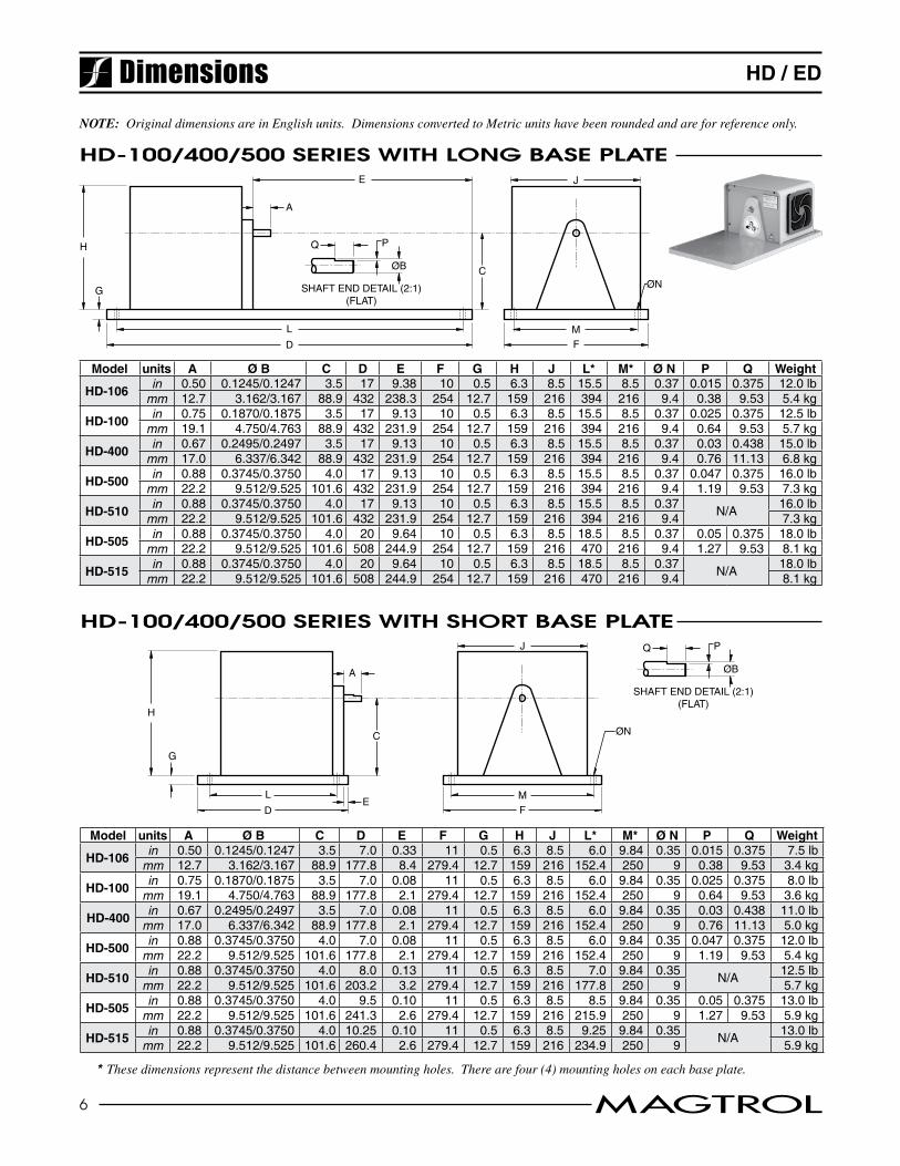
HD / EDDimensions
HD-100/400/500 series witH long Base plate
NOTE: Original dimensions are in English units. Dimensions converted to Metric units have been rounded and are for reference only.
E
A
H
J
ØN
MF
C
G
L
D
Q P
SHAFT END DETAIL (2:1)(FLAT)
ØB
Model units A Ø B C D E F G H J L* M* Ø N P Q Weight
HD-106in 0.50 0.1245/0.1247 3.5 17 9.38 10 0.5 6.3 8.5 15.5 8.5 0.37 0.015 0.375 12.0 lb
mm 12.7 3.162/3.167 88.9 432 238.3 254 12.7 159 216 394 216 9.4 0.38 9.53 5.4 kg
HD-100in 0.75 0.1870/0.1875 3.5 17 9.13 10 0.5 6.3 8.5 15.5 8.5 0.37 0.025 0.375 12.5 lb
mm 19.1 4.750/4.763 88.9 432 231.9 254 12.7 159 216 394 216 9.4 0.64 9.53 5.7 kg
HD-400in 0.67 0.2495/0.2497 3.5 17 9.13 10 0.5 6.3 8.5 15.5 8.5 0.37 0.03 0.438 15.0 lb
mm 17.0 6.337/6.342 88.9 432 231.9 254 12.7 159 216 394 216 9.4 0.76 11.13 6.8 kg
HD-500in 0.88 0.3745/0.3750 4.0 17 9.13 10 0.5 6.3 8.5 15.5 8.5 0.37 0.047 0.375 16.0 lb
mm 22.2 9.512/9.525 101.6 432 231.9 254 12.7 159 216 394 216 9.4 1.19 9.53 7.3 kg
HD-510in 0.88 0.3745/0.3750 4.0 17 9.13 10 0.5 6.3 8.5 15.5 8.5 0.37 N/A 16.0 lb
mm 22.2 9.512/9.525 101.6 432 231.9 254 12.7 159 216 394 216 9.4 7.3 kg
HD-505in 0.88 0.3745/0.3750 4.0 20 9.64 10 0.5 6.3 8.5 18.5 8.5 0.37 0.05 0.375 18.0 lb
mm 22.2 9.512/9.525 101.6 508 244.9 254 12.7 159 216 470 216 9.4 1.27 9.53 8.1 kg
HD-515in 0.88 0.3745/0.3750 4.0 20 9.64 10 0.5 6.3 8.5 18.5 8.5 0.37 N/A 18.0 lb
mm 22.2 9.512/9.525 101.6 508 244.9 254 12.7 159 216 470 216 9.4 8.1 kg
HD-100/400/500 series witH sHort Base plate
* These dimensions represent the distance between mounting holes. There are four (4) mounting holes on each base plate.
A
H
J
MF
C
G
L
D
ØN
E
Q P
SHAFT END DETAIL (2:1)(FLAT)
ØB
Model units A Ø B C D E F G H J L* M* Ø N P Q Weight
HD-106 in 0.50 0.1245/0.1247 3.5 7.0 0.33 11 0.5 6.3 8.5 6.0 9.84 0.35 0.015 0.375 7.5 lb
mm 12.7 3.162/3.167 88.9 177.8 8.4 279.4 12.7 159 216 152.4 250 9 0.38 9.53 3.4 kg
HD-100in 0.75 0.1870/0.1875 3.5 7.0 0.08 11 0.5 6.3 8.5 6.0 9.84 0.35 0.025 0.375 8.0 lb
mm 19.1 4.750/4.763 88.9 177.8 2.1 279.4 12.7 159 216 152.4 250 9 0.64 9.53 3.6 kg
HD-400in 0.67 0.2495/0.2497 3.5 7.0 0.08 11 0.5 6.3 8.5 6.0 9.84 0.35 0.03 0.438 11.0 lb
mm 17.0 6.337/6.342 88.9 177.8 2.1 279.4 12.7 159 216 152.4 250 9 0.76 11.13 5.0 kg
HD-500in 0.88 0.3745/0.3750 4.0 7.0 0.08 11 0.5 6.3 8.5 6.0 9.84 0.35 0.047 0.375 12.0 lb
mm 22.2 9.512/9.525 101.6 177.8 2.1 279.4 12.7 159 216 152.4 250 9 1.19 9.53 5.4 kg
HD-510in 0.88 0.3745/0.3750 4.0 8.0 0.13 11 0.5 6.3 8.5 7.0 9.84 0.35 N/A 12.5 lb
mm 22.2 9.512/9.525 101.6 203.2 3.2 279.4 12.7 159 216 177.8 250 9 5.7 kg
HD-505in 0.88 0.3745/0.3750 4.0 9.5 0.10 11 0.5 6.3 8.5 8.5 9.84 0.35 0.05 0.375 13.0 lb
mm 22.2 9.512/9.525 101.6 241.3 2.6 279.4 12.7 159 216 215.9 250 9 1.27 9.53 5.9 kg
HD-515in 0.88 0.3745/0.3750 4.0 10.25 0.10 11 0.5 6.3 8.5 9.25 9.84 0.35 N/A 13.0 lb
mm 22.2 9.512/9.525 101.6 260.4 2.6 279.4 12.7 159 216 234.9 250 9 5.9 kg
7 MAGTROL
HD / ED
* These dimensions represent the distance between mounting holes. There are four (4) mounting holes on each base plate.
E
A
H
J
MF
C
ØNG
LD
Q P
SHAFT END DETAIL (2:1)(FLAT)
ØB
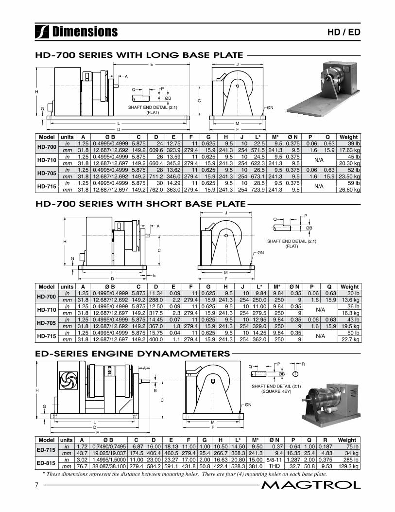
Model units A Ø B C D E F G H J L* M* Ø N P Q Weight
HD-700in 1.25 0.4995/0.4999 5.875 24 12.75 11 0.625 9.5 10 22.5 9.5 0.375 0.06 0.63 39 lb
mm 31.8 12.687/12.692 149.2 609.6 323.9 279.4 15.9 241.3 254 571.5 241.3 9.5 1.6 15.9 17.63 kg
HD-710in 1.25 0.4995/0.4999 5.875 26 13.59 11 0.625 9.5 10 24.5 9.5 0.375 N/A 45 lb
mm 31.8 12.687/12.697 149.2 660.4 345.2 279.4 15.9 241.3 254 622.3 241.3 9.5 20.30 kg
HD-705in 1.25 0.4995/0.4999 5.875 28 13.62 11 0.625 9.5 10 26.5 9.5 0.375 0.06 0.63 52 lb
mm 31.8 12.687/12.692 149.2 711.2 346.0 279.4 15.9 241.3 254 673.1 241.3 9.5 1.6 15.9 23.50 kg
HD-715in 1.25 0.4995/0.4999 5.875 30 14.29 11 0.625 9.5 10 28.5 9.5 0.375 N/A 59 lb
mm 31.8 12.687/12.697 149.2 762.0 363.0 279.4 15.9 241.3 254 723.9 241.3 9.5 26.60 kg
HD-700 series witH long Base plate
HD-700 series witH sHort Base plate
E
A
H
J
M
F
C ØNG
LD
QP
SHAFT END DETAIL (2:1)(FLAT)
ØB
Model units A Ø B C D E F G H J L* M* Ø N P Q Weight
HD-700in 1.25 0.4995/0.4999 5.875 11.34 0.09 11 0.625 9.5 10 9.84 9.84 0.35 0.06 0.63 30 lb
mm 31.8 12.687/12.692 149.2 288.0 2.2 279.4 15.9 241.3 254 250.0 250 9 1.6 15.9 13.6 kg
HD-710in 1.25 0.4995/0.4999 5.875 12.50 0.09 11 0.625 9.5 10 11.00 9.84 0.35 N/A 36 lb
mm 31.8 12.687/12.697 149.2 317.5 2.3 279.4 15.9 241.3 254 279.5 250 9 16.3 kg
HD-705in 1.25 0.4995/0.4999 5.875 14.45 0.07 11 0.625 9.5 10 12.95 9.84 0.35 0.06 0.63 43 lb
mm 31.8 12.687/12.692 149.2 367.0 1.8 279.4 15.9 241.3 254 329.0 250 9 1.6 15.9 19.5 kg
HD-715in 1.25 0.4995/0.4999 5.875 15.75 0.04 11 0.625 9.5 10 14.25 9.84 0.35 N/A 50 lb
mm 31.8 12.687/12.697 149.2 400.0 1.1 279.4 15.9 241.3 254 362.0 250 9 22.7 kg
Dimensions
eD-series engine Dynamometers
Model units A Ø B C D E F G H L* M* Ø N P Q R Weight
ED-715in 1.72 0.7490/0.7495 6.87 16.00 18.13 11.00 1.00 10.50 14.50 9.50 0.37 0.64 1.00 0.187 75 lb
mm 43.7 19.025/19.037 174.5 406.4 460.5 279.4 25.4 266.7 368.3 241.3 9.4 16.35 25.4 4.83 34 kg
ED-815in 3.02 1.4995/1.5000 11.00 23.00 23.27 17.00 2.00 16.63 20.80 15.00 5/8-11
THD1.287 2.00 0.375 285 lb
mm 76.7 38.087/38.100 279.4 584.2 591.1 431.8 50.8 422.4 528.3 381.0 32.7 50.8 9.53 129.3 kg
C
B
A
H
MF
ØNG
LD
E
QP
ØB
R
SHAFT END DETAIL (2:1)(SQUARE KEY)
8 MAGTROL
HD / ED
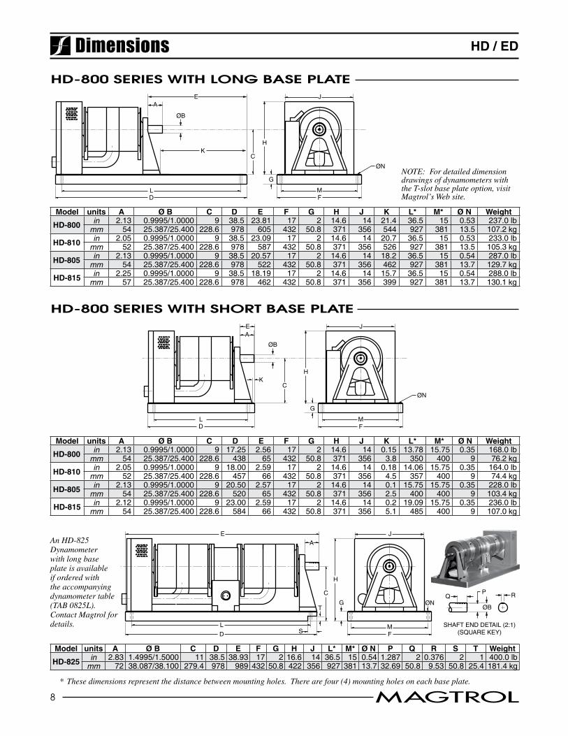
Model units A Ø B C D E F G H J L* M* Ø N P Q R S T Weight
HD-825 in 2.83 1.4995/1.5000 11 38.5 38.93 17 2 16.6 14 36.5 15 0.54 1.287 2 0.376 2 1 400.0 lbmm 72 38.087/38.100 279.4 978 989 432 50.8 422 356 927 381 13.7 32.69 50.8 9.53 50.8 25.4 181.4 kg
EA
H
J
ØN
MF
C
G
LD
K
ØB
E
A
H
J
QP
ØB
RØN
MF
C
GT
L
D
SHAFT END DETAIL (2:1)(SQUARE KEY)S
HD-800 series witH long Base plate
HD-800 series witH sHort Base plate
Model units A Ø B C D E F G H J K L* M* Ø N Weight
HD-800 in 2.13 0.9995/1.0000 9 17.25 2.56 17 2 14.6 14 0.15 13.78 15.75 0.35 168.0 lbmm 54 25.387/25.400 228.6 438 65 432 50.8 371 356 3.8 350 400 9 76.2 kg
HD-810 in 2.05 0.9995/1.0000 9 18.00 2.59 17 2 14.6 14 0.18 14.06 15.75 0.35 164.0 lbmm 52 25.387/25.400 228.6 457 66 432 50.8 371 356 4.5 357 400 9 74.4 kg
HD-805 in 2.13 0.9995/1.0000 9 20.50 2.57 17 2 14.6 14 0.1 15.75 15.75 0.35 228.0 lbmm 54 25.387/25.400 228.6 520 65 432 50.8 371 356 2.5 400 400 9 103.4 kg
HD-815 in 2.12 0.9995/1.0000 9 23.00 2.59 17 2 14.6 14 0.2 19.09 15.75 0.35 236.0 lbmm 54 25.387/25.400 228.6 584 66 432 50.8 371 356 5.1 485 400 9 107.0 kg
EA
H
J
ØN
MF
C
G
LD
K
ØB
An HD-825 Dynamometer with long base plate is available if ordered with the accompanying dynamometer table (TAB 0825L). Contact Magtrol for details.
Dimensions
* These dimensions represent the distance between mounting holes. There are four (4) mounting holes on each base plate.
NOTE: For detailed dimension drawings of dynamometers with the T-slot base plate option, visit Magtrol’s Web site.
Model units A Ø B C D E F G H J K L* M* Ø N Weight
HD-800 in 2.13 0.9995/1.0000 9 38.5 23.81 17 2 14.6 14 21.4 36.5 15 0.53 237.0 lbmm 54 25.387/25.400 228.6 978 605 432 50.8 371 356 544 927 381 13.5 107.2 kg
HD-810 in 2.05 0.9995/1.0000 9 38.5 23.09 17 2 14.6 14 20.7 36.5 15 0.53 233.0 lbmm 52 25.387/25.400 228.6 978 587 432 50.8 371 356 526 927 381 13.5 105.3 kg
HD-805 in 2.13 0.9995/1.0000 9 38.5 20.57 17 2 14.6 14 18.2 36.5 15 0.54 287.0 lbmm 54 25.387/25.400 228.6 978 522 432 50.8 371 356 462 927 381 13.7 129.7 kg
HD-815 in 2.25 0.9995/1.0000 9 38.5 18.19 17 2 14.6 14 15.7 36.5 15 0.54 288.0 lbmm 57 25.387/25.400 228.6 978 462 432 50.8 371 356 399 927 381 13.7 130.1 kg
9 MAGTROL
HD / ED
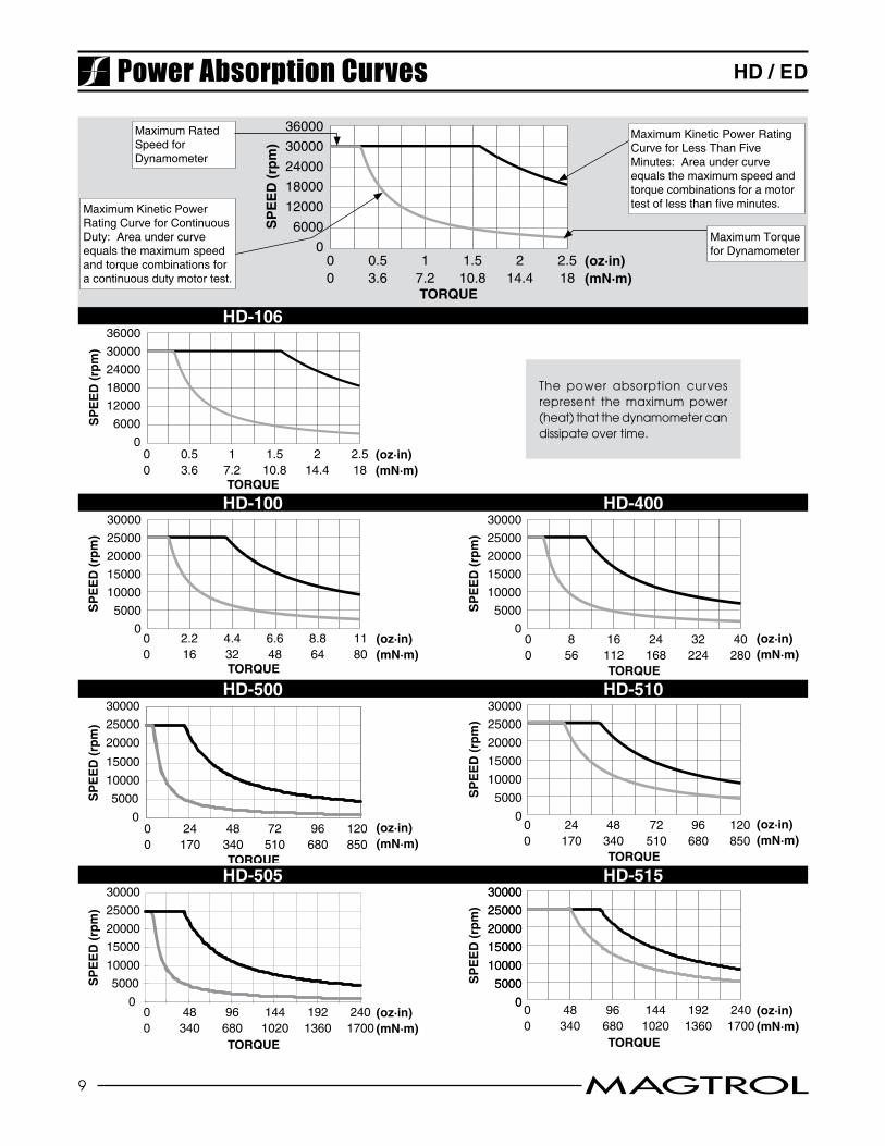
Maximum Torque for Dynamometer
Maximum Kinetic Power Rating Curve for Continuous Duty: Area under curve equals the maximum speed and torque combinations for a continuous duty motor test.
Maximum Rated Speed for Dynamometer
Maximum Kinetic Power Rating Curve for Less Than Five Minutes: Area under curve equals the maximum speed and torque combinations for a motor test of less than five minutes.
TORQUE
SP
EE
D (
rpm
)
0
6000
12000
18000
24000
30000
36000
00
0.53.6
17.2
1.510.8
214.4
2.518
(oz·in)(mN·m)
Power Absorption Curves
HD-106
TORQUE
SP
EE
D (
rpm
)
0
6000
12000
18000
24000
30000
36000
00
0.53.6
17.2
1.510.8
214.4
2.518
(oz·in)(mN·m)
The power absorption curves represent the maximum power (heat) that the dynamometer can dissipate over time.
HD-100 HD-400
TORQUE
SP
EE
D (
rpm
)
0
5000
10000
15000
20000
25000
30000
00
2.216
4.432
6.648
8.864
1180
(oz·in)(mN·m)
TORQUE
SP
EE
D (
rpm
)
0
5000
10000
15000
20000
25000
30000
00
856
16112
24168
32224
40280
(oz·in)(mN·m)
HD-500 HD-510
TORQUE
SP
EE
D (
rpm
)
00
24170
48340
72510
96680
120850
(oz·in)(mN·m)
0
5000
10000
15000
20000
25000
30000
TORQUE
SP
EE
D (
rpm
)
0
5000
10000
15000
20000
25000
30000
00
24170
48340
72510
96680
120850
(oz·in)(mN·m)
HD-505 HD-515
TORQUE
SP
EE
D (
rpm
)
00
48340
96680
1441020
1921360
2401700
(oz·in)(mN·m)
0
5000
10000
15000
20000
25000
30000
TORQUE
SP
EE
D (
rpm
)
00
48340
96680
1441020
1921360
2401700
(oz·in)(mN·m)
0
5000
10000
15000
20000
25000
30000
0
5000
10000
15000
20000
25000
30000
10 MAGTROL
HD / ED
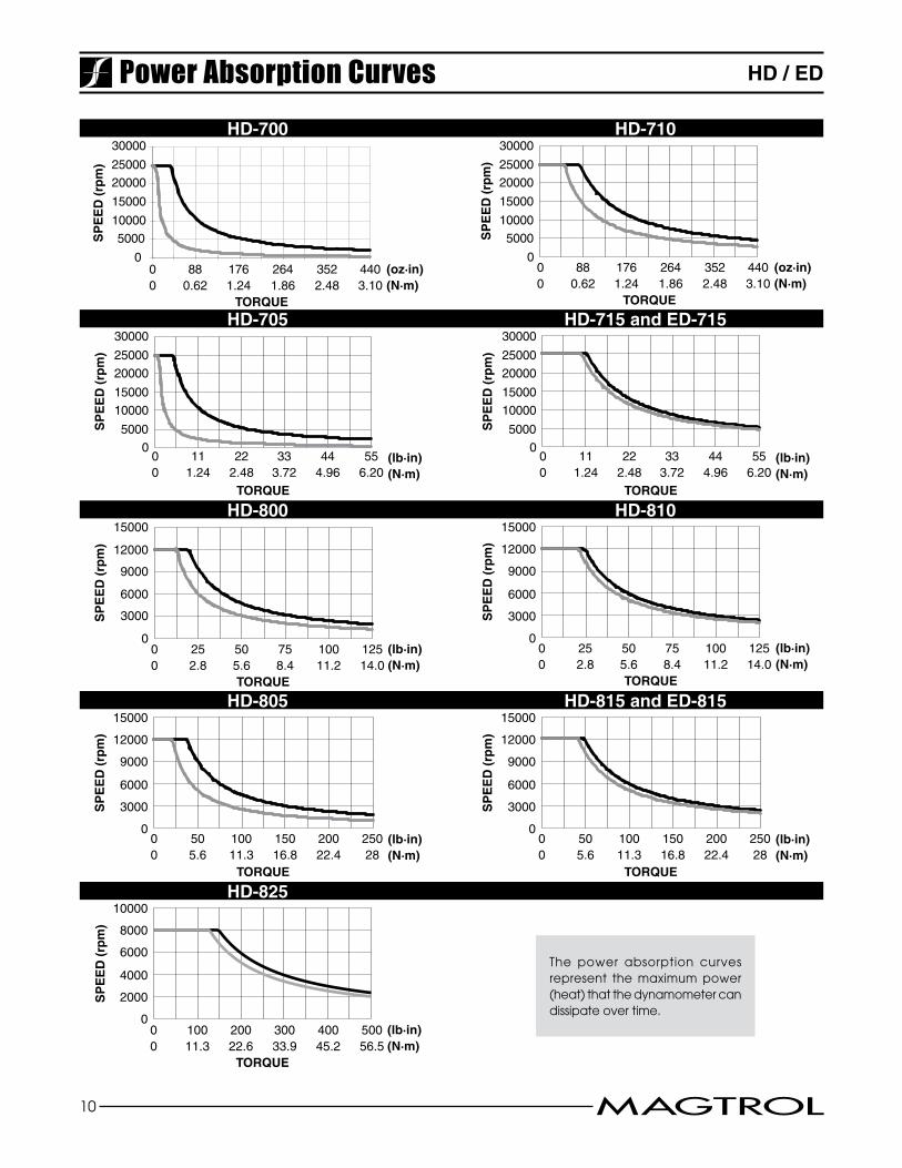
HD-700 HD-710
TORQUE
SP
EE
D (
rpm
)
(oz·in)(N·m)
0
500010000
15000
2000025000
30000
00
880.62
1761.24
2641.86
3522.48
4403.10
SP
EE
D (
rpm
)
0
500010000
15000
2000025000
30000
TORQUE
(oz·in)(N·m)
00
880.62
1761.24
2641.86
3522.48
4403.10
HD-705 HD-715 and ED-715
TORQUE
SP
EE
D (
rpm
)
(lb·in)(N·m)
0
5000
10000
15000
20000
25000
30000
00
111.24
222.48
333.72
444.96
556.20
TORQUES
PE
ED
(rp
m)
(lb·in)(N·m)
0
5000
10000
15000
20000
25000
30000
00
111.24
222.48
333.72
444.96
556.20
HD-800 HD-810
TORQUE
SP
EE
D (
rpm
)
0
3000
6000
9000
12000
15000
00
252.8
505.6
758.4
10011.2
12514.0
(lb·in)(N·m)
TORQUE
SP
EE
D (
rpm
)
0
3000
6000
9000
12000
15000
00
252.8
505.6
758.4
10011.2
12514.0
(lb·in)(N·m)
HD-805 HD-815 and ED-815
TORQUE
SP
EE
D (
rpm
)
0
3000
6000
9000
12000
15000
00
505.6
10011.3
15016.8
20022.4
25028
(lb·in)(N·m)
TORQUE
SP
EE
D (
rpm
)
0
3000
6000
9000
12000
15000
00
505.6
10011.3
15016.8
20022.4
25028
(lb·in)(N·m)
HD-825
TORQUE
SP
EE
D (
rpm
)
0
2000
4000
6000
8000
10000
00
10011.3
20022.6
30033.9
40045.2
50056.5
(lb·in)(N·m)
The power absorption curves represent the maximum power (heat) that the dynamometer can dissipate over time.
Power Absorption Curves
11 MAGTROL
HD / EDSystem Configurations
1o----------o----o----------
HD / EDDYNAMOMETER
PC
USB
M-TEST
DSP7001 CONTROLLER
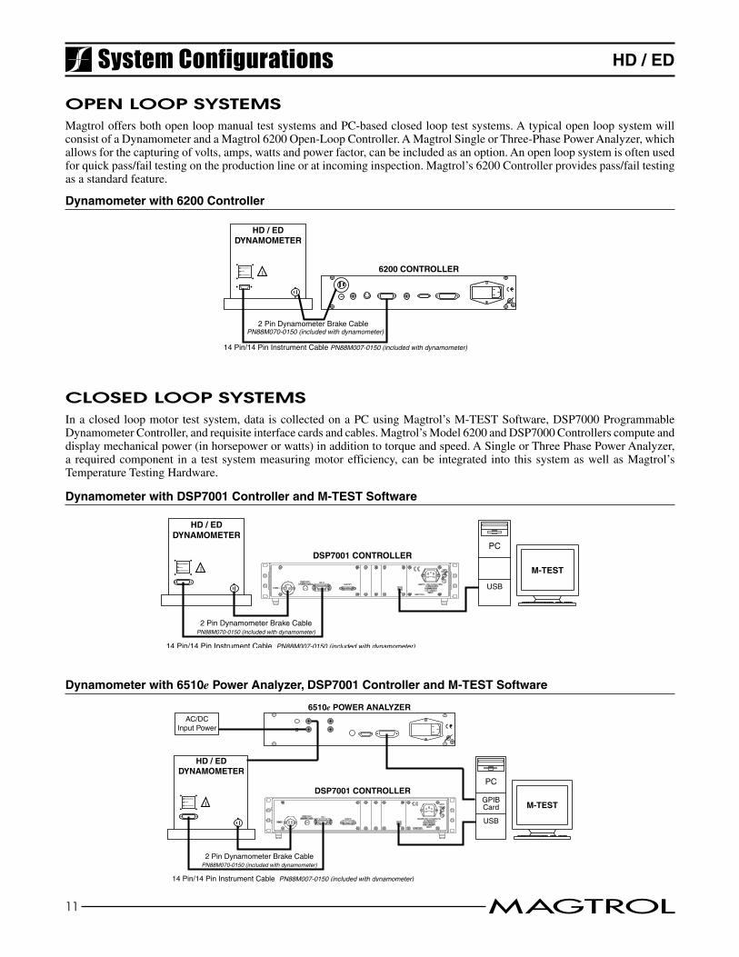
2 Pin Dynamometer Brake CablePN88M070-0150 (included with dynamometer)
14 Pin/14 Pin Instrument Cable PN88M007-0150 (included with dynamometer)
Dynamometer with 6200 Controller
Dynamometer with DSP7001 Controller and M-TEST Software
1 o---------- o---- o----------
2 Pin Dynamometer Brake Cable PN88M070-0150 (included with dynamometer)
6200 CONTROLLER
14 Pin/14 Pin Instrument Cable PN88M007-0150 (included with dynamometer)
HD / EDDYNAMOMETER
1o----------o----o----------
HD / EDDYNAMOMETER
PC
USB
M-TEST
DSP7001 CONTROLLER
2 Pin Dynamometer Brake CablePN88M070-0150 (included with dynamometer)
14 Pin/14 Pin Instrument Cable PN88M007-0150 (included with dynamometer)
6510e POWER ANALYZERAC/DC
Input Power
GPIBCard
open loop systemsMagtroloffersbothopenloopmanualtestsystemsandPC-basedclosedlooptestsystems.AtypicalopenloopsystemwillconsistofaDynamometerandaMagtrol6200Open-LoopController.AMagtrolSingleorThree-PhasePowerAnalyzer,whichallowsforthecapturingofvolts,amps,wattsandpowerfactor,canbeincludedasanoption.Anopenloopsystemisoftenusedforquickpass/failtestingontheproductionlineoratincominginspection.Magtrol’s6200Controllerprovidespass/failtestingasastandardfeature.
closeD loop systemsInaclosedloopmotor testsystem,data iscollectedonaPCusingMagtrol’sM-TESTSoftware,DSP7000ProgrammableDynamometerController,andrequisiteinterfacecardsandcables.Magtrol’sModel6200andDSP7000Controllerscomputeanddisplaymechanicalpower(inhorsepowerorwatts)inadditiontotorqueandspeed.ASingleorThreePhasePowerAnalyzer,a requiredcomponent ina test systemmeasuringmotorefficiency,canbe integrated into this systemaswellasMagtrol’sTemperatureTestingHardware.
Dynamometer with 6510e Power Analyzer, DSP7001 Controller and M-TEST Software
12 MAGTROL
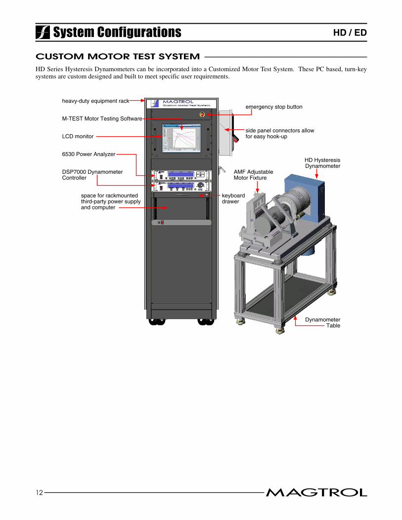
HD / EDSystem Configurationscustom motor test systemHDSeriesHysteresisDynamometerscanbeincorporatedintoaCustomizedMotorTestSystem.ThesePCbased,turn-keysystemsarecustomdesignedandbuilttomeetspecificuserrequirements.
heavy-duty equipment rack
M-TEST Motor Testing Software
AMF Adjustable Motor Fixture
Dynamometer Table
HD Hysteresis Dynamometer
DSP7000 Dynamometer Controller
6530 Power Analyzer
keyboard drawer
side panel connectors allow for easy hook-up
space for rackmountedthird-party power supply and computer
LCD monitor
emergency stop button
HD / ED
Duetothecontinualdevelopmentofourproducts,wereservetherighttomodifyspecificationswithoutforewarning.
Ordering InformationorDering inFormation
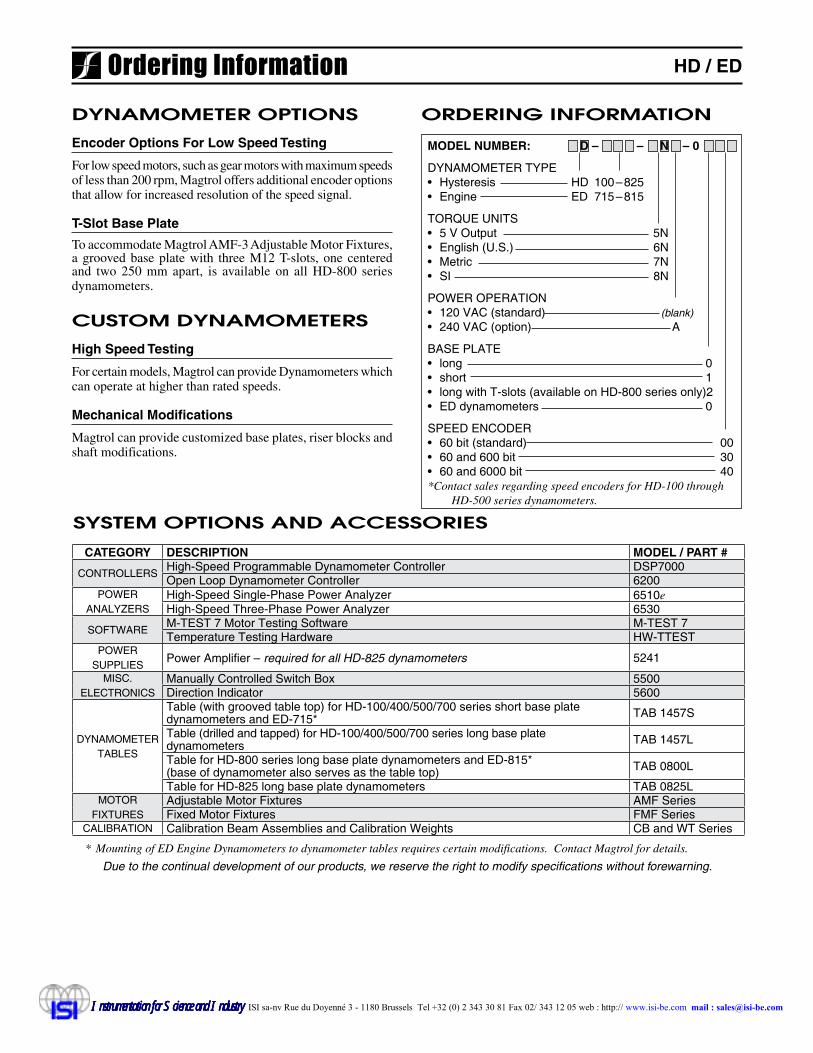
system options anD accessories
CATEGORY DESCRIPTION MODEL / PART #
CONTROLLERS High-Speed Programmable Dynamometer Controller DSP7000Open Loop Dynamometer Controller 6200
POWER ANALYZERS
High-Speed Single-Phase Power Analyzer 6510eHigh-Speed Three-Phase Power Analyzer 6530
SOFTWARE M-TEST 7 Motor Testing Software M-TEST 7Temperature Testing Hardware HW-TTEST
POWERSUPPLIES
Power Amplifier – requiredforallHD-825dynamometers 5241
MISC.ELECTRONICS
Manually Controlled Switch Box 5500Direction Indicator 5600
DYNAMOMETERTABLES
Table (with grooved table top) for HD-100/400/500/700 series short base plate dynamometers and ED-715* TAB 1457S
Table (drilled and tapped) for HD-100/400/500/700 series long base plate dynamometers TAB 1457L
Table for HD-800 series long base plate dynamometers and ED-815* (base of dynamometer also serves as the table top) TAB 0800L
Table for HD-825 long base plate dynamometers TAB 0825LMOTOR
FIXTURESAdjustable Motor Fixtures AMF SeriesFixed Motor Fixtures FMF Series
CALIBRATION Calibration Beam Assemblies and Calibration Weights CB and WT Series
Dynamometer options
Encoder Options For Low Speed Testing
Forlowspeedmotors,suchasgearmotorswithmaximumspeedsoflessthan200rpm,Magtroloffersadditionalencoderoptionsthatallowforincreasedresolutionofthespeedsignal.
T-Slot Base Plate
ToaccommodateMagtrolAMF-3AdjustableMotorFixtures,agroovedbaseplatewith threeM12T-slots,onecenteredand two 250 mm apart, is available on all HD-800 seriesdynamometers.
custom Dynamometers
High Speed Testing
Forcertainmodels,MagtrolcanprovideDynamometerswhichcanoperateathigherthanratedspeeds.
Mechanical Modifications
Magtrolcanprovidecustomizedbaseplates,riserblocksandshaftmodifications.
* Mounting of ED Engine Dynamometers to dynamometer tables requires certain modifications. Contact Magtrol for details.
MODEL NUMBER: D – – N – 0
DYNAMOMETER TYPE• Hysteresis HD 100 – 825 • Engine ED 715 – 815
TORQUE UNITS• 5 V Output 5N• English (U.S.) 6N• Metric 7N• SI 8N
POWER OPERATION• 120 VAC (standard) (blank) • 240 VAC (option) A
BASE PLATE• long 0• short 1• long with T-slots (available on HD-800 series only) 2• ED dynamometers 0
SPEED ENCODER• 60 bit (standard) 00• 60 and 600 bit 30• 60 and 6000 bit 40*Contact sales regarding speed encoders for HD-100 through
HD-500 series dynamometers.
IIIInnnnstrstrustrustruumentmentamentamentaation for Science tion for Science ation for Science ation for Science aannnndddd I I IInnnndddduuuusssstrytrytrytry ISI sa-nv Rue du Doyenné 3 - 1180 Brussels Tel +32 (0) 2 343 30 81 Fax 02/ 343 12 05 web : http:// www.isi-be.com mail : [email protected]