Embed Size (px)
Citation preview
Contents
Typical Applications 2
Principal Features 3
Oxidation Resistance 4
Carburization Resistance 7
Resistance to Chlorine-BearingEnvironments 10
Nitriding Resistance 11
Physical Properties 12
Modulus of Elasticity 13
Tensile Properties 14
Creep and Rupture Properties 15
Thermal Stability 16
Fabrication Characteristics 16
Welding 17
Health & Safety 19
Sales Office Addresses 20
A nickel-chromium-aluminum-iron alloy with outstandingresistance to oxidation.
H-3008C
HIGH-TEMPERATURE ALLOYS
HAYNES® 214™ alloy
2HAYNES 214 alloy
APPLICATIONS
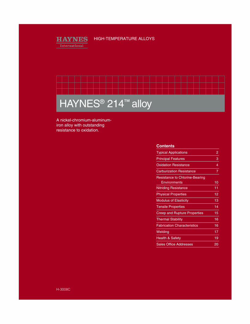
This 214 alloy flamehood remained in service for16 months in an application where other nickelalloy hoods required replacement every three tofour months. The alloy component was subjectedto direct flame impingement during the entireperiod in an automotive products plant.
©1996 Haynes International, Inc.
HAYNES® 214™ alloy is gaining rapid accep-tance for use in honeycomb seals because of itsoutstanding oxidation resistance. The seals aremade of thin gage foil and are used to preventleakage between different stages in gas turbineengines. Such seals contribute to an engines fuelefficiency.
The burner assembly at left failed after 450 cyclesbetween minus 55 and 2000°F (minus 50 and1095°C.) A 214 alloy burner was still in goodshape after 2000 cycles in the same test. Theburners were cycled from low to high tempera-tures in about five minutes, held for a 15-minuteburn, and then rapid-air cooled.
Section of a 214 alloy belt which was removedafter 3,000 hours at 1800°F (980°C) in achinaware decorating kiln. The belt showed onlyminimal wear and oxidation attack. Use of 214alloy in this application has helped reduce thetime of the operation from eight or twelve hours,to less than 30 minutes.
3
PRINCIPAL FEATURES
Available Product FormsHAYNES 214 alloy is available in theform of plate, sheet, strip, billet, bar,and wire.
Applicable SpecificationsHAYNES 214 alloy is covered by DINspecification number 17744 No.2.4646for all forms, and a full range ofHaynes internal product specifications.Please consult Haynes Internationalfor details.
ApplicationsHAYNES 214 alloy combines proper-ties which make it very suitable forservice in relatively low-stress, high-temperature oxidizing environments,where the utmost in resistance tooxidation or scale exfoliation isneeded. Its resistance to suchenvironments persists to temperaturesas high as 2400°F (1315°C), althoughstrength limitations may apply.Applications can include "Clean Firing"uses such as mesh belts, trays andfixtures for firing of pottery and finechina, and the heat treatment ofelectronic devices and technical gradeceramics.
In the gas turbine industry, 214 alloy isused for foil construction honeycombseals, combustor splash plates, andother static oxidation - limited parts.The automotive industry has applica-tions for 214 alloy in catalytic converterinternals, and it is used as a burnercup material in auxiliary heaters formilitary vehicles.
In the industrial heating market, 214alloy is used for highly specializedapplications such as refractoryanchors, furnace flame hoods, androtary calciners for processing chloridecompounds. It is also used for parts inhigh temperature chlorine-contami-nated environments, such as hospitalwaste incinerator internals.
Excellent OxidationResistanceHAYNES® 214™ alloy is a nickel-chromium-aluminum-iron alloy,designed to provide the optimum inhigh-temperature oxidation resistancefor a wrought austenitic material, whileat the same time allowing for conven-tional forming and joining. Intendedprincipally for use at temperatures of1750°F (955°C) and above, 214 alloyexhibits resistance to oxidation that farexceeds virtually all conventional heat-resistant wrought alloys at thesetemperatures. This is attributable tothe formation of a tightly adherentAl2O3-type protective oxide scale,which forms in preference to chromiumoxide scales at these high tempera-tures. At temperatures below 1750°F(955°C), 214 alloy develops an oxidescale which is a mixture of chromiumand aluminum oxides. This mixedscale is somewhat less protective, butstill affords 214 alloy oxidationresistance equal to the best nickel-base alloys.
The higher temperature Al2O
3- type
scale which 214 alloy forms alsoprovides the alloy with excellentresistance to carburization, nitridingand corrosion in chlorine-bearingoxidizing environments.
FabricationHAYNES 214 alloy is similar in manyrespects to high aluminum contentnickel-base alloys which are intendedto be age-hardened by intermediatetemperature heat treatment. Ifexposed at temperatures in the rangeof 1100-1700°F (595-925°C), 214 alloywill exhibit age-hardening as a result ofthe formation of a second phase,gamma prime (Ni3Al). This also resultsin a significant loss of intermediate andlow temperature tensile ductility. As aconsequence of this, 214 alloy issusceptible to strain-age crackingwhen highly-stressed, highly-
HAYNES 214 alloy
restrained, welded components areslowly heated through the intermediatetemperature regime. This behavior isthe same as that exhibited by highaluminum + titanium content superal-loys, such as Waspaloy or R-41 alloys.The keys avoiding this problem are tominimize weldment restraint throughappropriate component design, and/orheat rapidly through the 1100-1700°F(595-925°C) temperature range duringpost-fabrication heat treatment (or first-use heat up).
With the exception of the aboveconsideration, HAYNES 214 alloydoes exhibit good forming and weldingcharacteristics. It may be forged orotherwise hot-worked, providing it isheld at 2100°F (1150°C) for a timesufficient to bring the entire piece totemperature. Its room temperaturetensile ductility is also high enough toallow the alloy to be formed by cold-working. All cold or hot-worked partsshould be annealed and rapidly cooledin order to restore the best balance ofproperties.
The alloy can be welded by a variety oftechniques, including gas tungsten arc(TIG), gas metal arc (MIG) or shieldedmetal arc (coated electrode) welding.
Heat-TreatmentHAYNES 214 alloy is furnished in thesolution heat-treated condition, unlessotherwise specified. The alloy isnormally solution heat-treated at2000°F (1095°C) and rapidly cooled orquenched for optimum properties.Heat treating at temperatures belowthe solution heat-treating temperaturewill result in grain boundary carbideprecipitation and, below 1750°F(955°C), precipitation of gamma primephase. Such lower temperature age-hardening heat treatments are notsuggested.
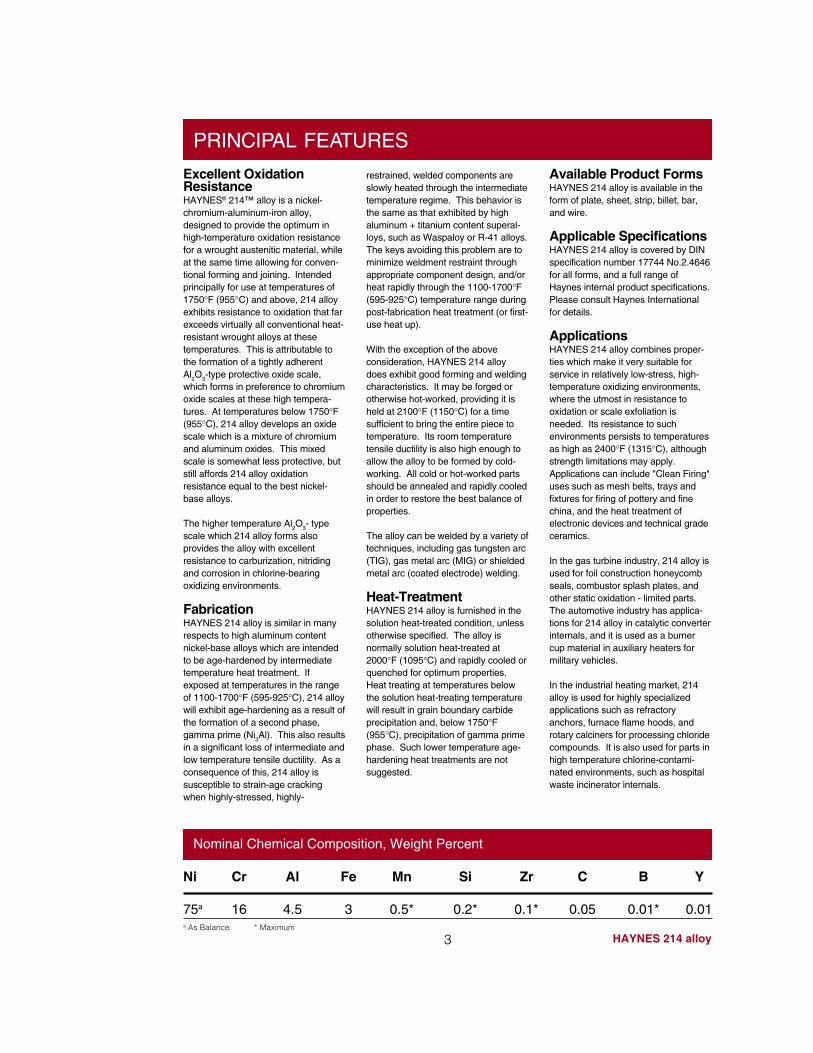
Nominal Chemical Composition, Weight Percent
Ni Cr Al Fe Mn Si Zr C B Y
75a 16 4.5 3 0.5* 0.2* 0.1* 0.05 0.01* 0.01a As Balance * Maximum
Average Metal Affected in 1008 Hours**
4
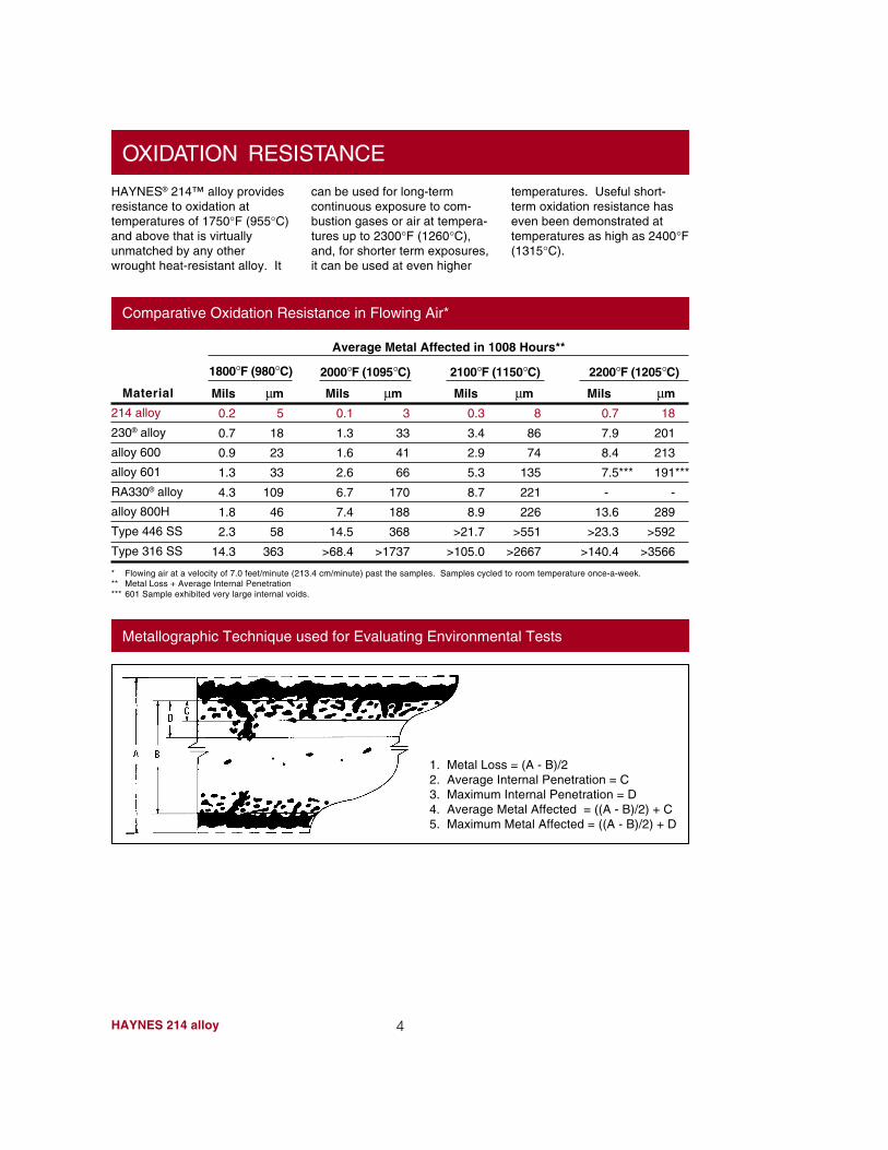
HAYNES® 214™ alloy providesresistance to oxidation attemperatures of 1750°F (955°C)and above that is virtuallyunmatched by any otherwrought heat-resistant alloy. It
can be used for long-termcontinuous exposure to com-bustion gases or air at tempera-tures up to 2300°F (1260°C),and, for shorter term exposures,it can be used at even higher
temperatures. Useful short-term oxidation resistance haseven been demonstrated attemperatures as high as 2400°F(1315°C).
OXIDATION RESISTANCE
HAYNES 214 alloy
Comparative Oxidation Resistance in Flowing Air*
Material
214 alloy
230® alloy
alloy 600
alloy 601
RA330® alloy
alloy 800H
Type 446 SS
Type 316 SS
Mils µm
0.7 18
7.9 201
8.4 213
7.5*** 191***
- -
13.6 289
>23.3 >592
>140.4 >3566
Mils µm
0.3 8
3.4 86
2.9 74
5.3 135
8.7 221
8.9 226
>21.7 >551
>105.0 >2667
Mils µm
0.1 3
1.3 33
1.6 41
2.6 66
6.7 170
7.4 188
14.5 368
>68.4 >1737
2200°F (1205°C)2100°F (1150°C)2000°F (1095°C)1800°F (980°C)
Mils µm
0.2 5
0.7 18
0.9 23
1.3 33
4.3 109
1.8 46
2.3 58
14.3 363
* Flowing air at a velocity of 7.0 feet/minute (213.4 cm/minute) past the samples. Samples cycled to room temperature once-a-week.** Metal Loss + Average Internal Penetration*** 601 Sample exhibited very large internal voids.
Metallographic Technique used for Evaluating Environmental Tests
1. Metal Loss = (A - B)/22. Average Internal Penetration = C3. Maximum Internal Penetration = D4. Average Metal Affected = ((A - B)/2) + C5. Maximum Metal Affected = ((A - B)/2) + D
5 HAYNES 214 alloy
Comparative Oxidation in Flowing Air 2100°F (1150°C)
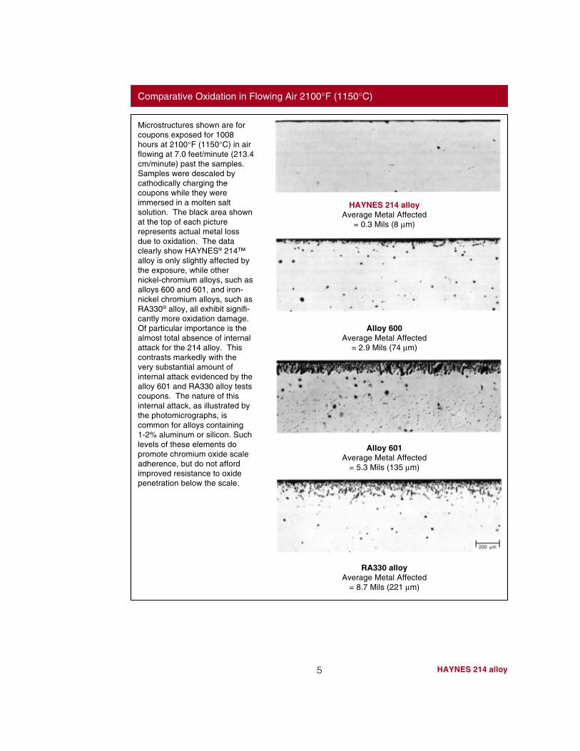
Microstructures shown are forcoupons exposed for 1008hours at 2100°F (1150°C) in airflowing at 7.0 feet/minute (213.4cm/minute) past the samples.Samples were descaled bycathodically charging thecoupons while they wereimmersed in a molten saltsolution. The black area shownat the top of each picturerepresents actual metal lossdue to oxidation. The dataclearly show HAYNES® 214™alloy is only slightly affected bythe exposure, while othernickel-chromium alloys, such asalloys 600 and 601, and iron-nickel chromium alloys, such asRA330® alloy, all exhibit signifi-cantly more oxidation damage.Of particular importance is thealmost total absence of internalattack for the 214 alloy. Thiscontrasts markedly with thevery substantial amount ofinternal attack evidenced by thealloy 601 and RA330 alloy testscoupons. The nature of thisinternal attack, as illustrated bythe photomicrographs, iscommon for alloys containing1-2% aluminum or silicon. Suchlevels of these elements dopromote chromium oxide scaleadherence, but do not affordimproved resistance to oxidepenetration below the scale.
HAYNES 214 alloyAverage Metal Affected
= 0.3 Mils (8 µm)
Alloy 600Average Metal Affected
= 2.9 Mils (74 µm)
Alloy 601Average Metal Affected
= 5.3 Mils (135 µm)
RA330 alloyAverage Metal Affected
= 8.7 Mils (221 µm)
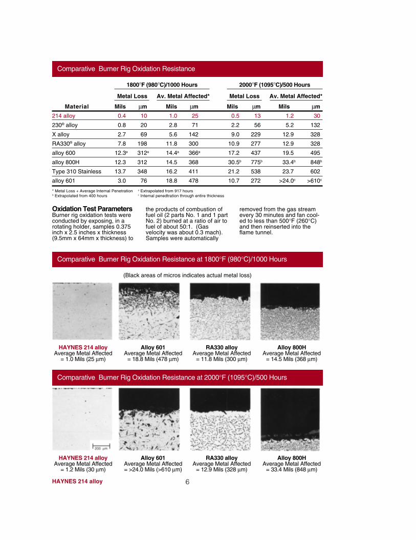
Comparative Burner Rig Oxidation Resistance
* Metal Loss + Average Internal Penetration a Extrapolated from 917 hoursb Extrapolated from 400 hours c Internal penedtration through entire thickness
Mils µm
1.2 30
5.2 132
12.9 328
12.9 328
19.5 495
33.4b 848b
23.7 602
>24.0c >610c
Mils µm
0.5 13
2.2 56
9.0 229
10.9 277
17.2 437
30.5b 775b
21.2 538
10.7 272
Material
214 alloy
230® alloy
X alloy
RA330® alloy
alloy 600
alloy 800H
Type 310 Stainless
alloy 601
Mils µm
1.0 25
2.8 71
5.6 142
11.8 300
14.4a 366a
14.5 368
16.2 411
18.8 478
Mils µm
0.4 10
0.8 20
2.7 69
7.8 198
12.3a 312a
12.3 312
13.7 348
3.0 76
1800°F (980°C)/1000 Hours 2000°F (1095°C)/500 Hours
Metal Loss Av. Metal Affected* Metal Loss Av. Metal Affected*
Oxidation Test ParametersBurner rig oxidation tests wereconducted by exposing, in arotating holder, samples 0.375inch x 2.5 inches x thickness(9.5mm x 64mm x thickness) to
the products of combustion offuel oil (2 parts No. 1 and 1 partNo. 2) burned at a ratio of air tofuel of about 50:1. (Gasvelocity was about 0.3 mach).Samples were automatically
removed from the gas streamevery 30 minutes and fan cool-ed to less than 500°F (260°C)and then reinserted into theflame tunnel.
HAYNES 214 alloy 6
Comparative Burner Rig Oxidation Resistance at 1800°F (980°C)/1000 Hours
(Black areas of micros indicates actual metal loss)
HAYNES 214 alloyAverage Metal Affected
= 1.0 Mils (25 µm)
Alloy 601Average Metal Affected
= 18.8 Mils (478 µm)
RA330 alloyAverage Metal Affected
= 11.8 Mils (300 µm)
Alloy 800HAverage Metal Affected
= 14.5 Mils (368 µm)
Comparative Burner Rig Oxidation Resistance at 2000°F (1095°C)/500 Hours
HAYNES 214 alloyAverage Metal Affected
= 1.2 Mils (30 µm)
Alloy 601Average Metal Affected= >24.0 Mils (>610 µm)
RA330 alloyAverage Metal Affected
= 12.9 Mils (328 µm)
Alloy 800HAverage Metal Affected
= 33.4 Mils (848 µm)
7 HAYNES 214 alloy
CARBURIZATION RESISTANCE
HAYNES® 214™ alloy has verygood resistance to carburiza-tion, as measured in both pack-ed graphite exposure tests andmixed gas exposure tests.Results for these tests arepresented in the following
pages. All results are pre-sented in terms of the mass ofcarbon absorption per unit area,which was obtained from theequation M = C(W/A) where M= the mass of carbon absorp-tion per unit area (mg/cm2). C =
difference in carbon (weightfraction) before and afterexposure , W = weight of theunexposed specimen (mg) andA = surface area of the speci-men exposed to the test envi-ronment (cm2).
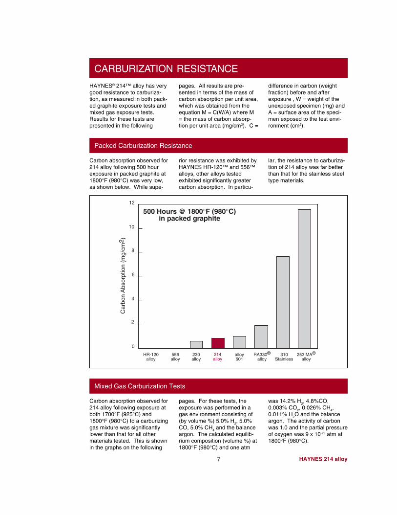
Packed Carburization Resistance
Carbon absorption observed for214 alloy following 500 hourexposure in packed graphite at1800°F (980°C) was very low,as shown below. While supe-
rior resistance was exhibited byHAYNES HR-120™ and 556™alloys, other alloys testedexhibited significantly greatercarbon absorption. In particu-
lar, the resistance to carburiza-tion of 214 alloy was far betterthan that for the stainless steeltype materials.
Mixed Gas Carburization Tests
pages. For these tests, theexposure was performed in agas environment consisting of(by volume %) 5.0% H
2, 5.0%
CO, 5.0% CH4 and the balance
argon. The calculated equilib-rium composition (volume %) at1800°F (980°C) and one atm
was 14.2% H2, 4.8%CO,
0.003% CO2, 0.026% CH
4,
0.011% H2O and the balance
argon. The activity of carbonwas 1.0 and the partial pressureof oxygen was 9 x 10-22 atm at1800°F (980°C).
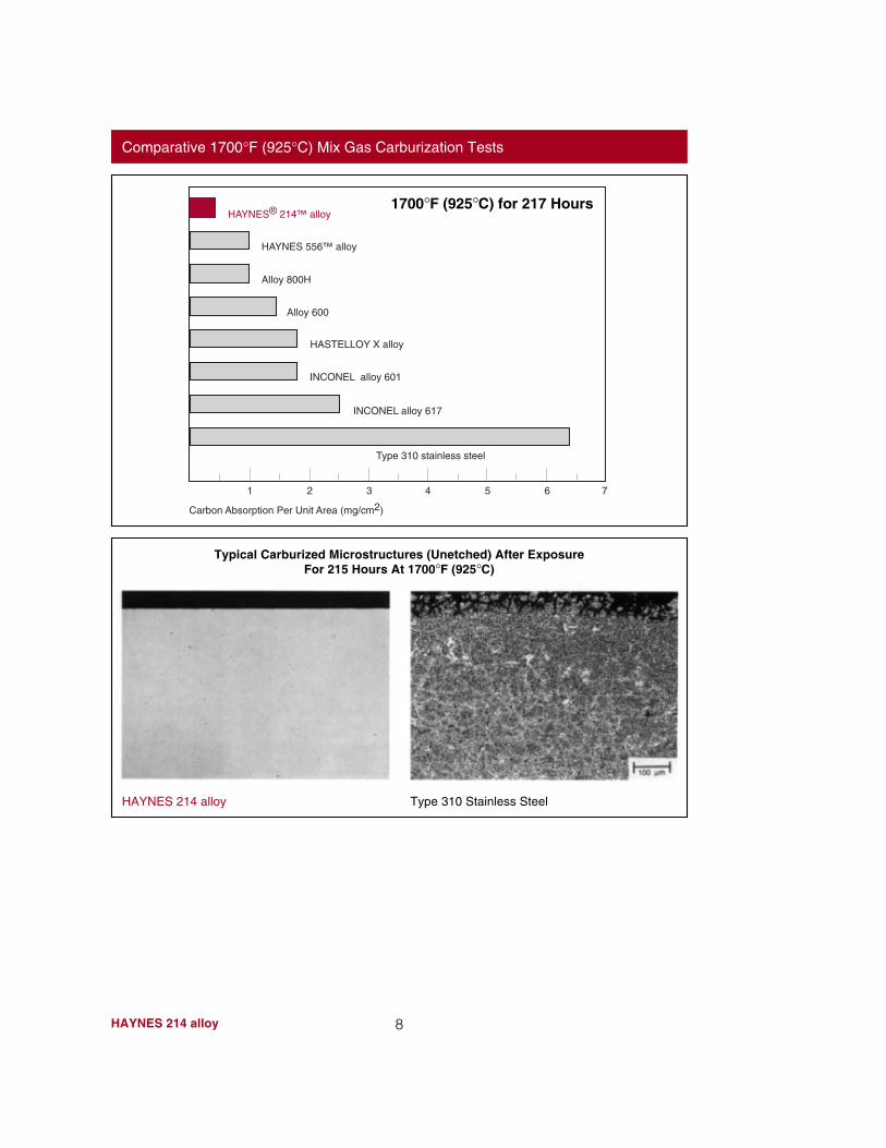
Carbon absorption observed for214 alloy following exposure atboth 1700°F (925°C) and1800°F (980°C) to a carburizinggas mixture was significantlylower than that for all othermaterials tested. This is shownin the graphs on the following
500 Hours @ 1800°F (980°C)in packed graphite
556alloy
2
4
6
0
8
10
12
Car
bon
Abs
orpt
ion
(mg/
cm2 )
HR-120alloy
253 MA®alloy
310Stainless
RA330®alloy
alloy601
230alloy
214alloy
8HAYNES 214 alloy
Comparative 1700°F (925°C) Mix Gas Carburization Tests
Typical Carburized Microstructures (Unetched) After ExposureFor 215 Hours At 1700°F (925°C)
HAYNES 214 alloy Type 310 Stainless Steel
1700°F (925°C) for 217 Hours
1 3 42 5 76
Type 310 stainless steel
INCONEL alloy 617
INCONEL alloy 601
HASTELLOY X alloy
Alloy 600
Alloy 800H
HAYNES 556™ alloy
Carbon Absorption Per Unit Area (mg/cm2)
HAYNES® 214™ alloy
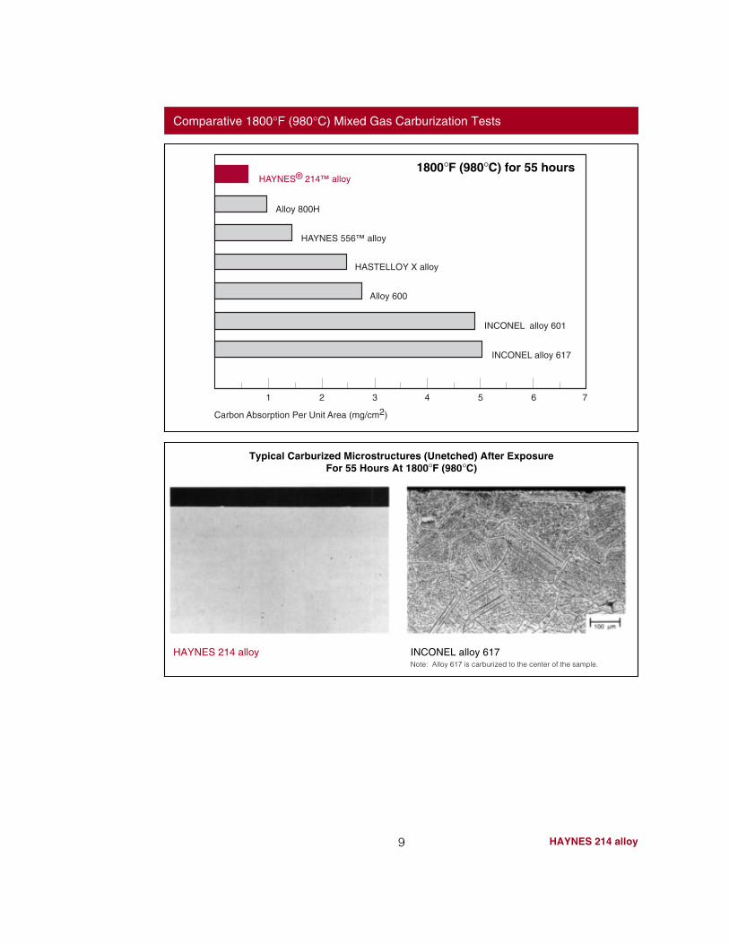
Comparative 1800°F (980°C) Mixed Gas Carburization Tests
1800°F (980°C) for 55 hours
9 HAYNES 214 alloy
Typical Carburized Microstructures (Unetched) After ExposureFor 55 Hours At 1800°F (980°C)
HAYNES 214 alloy INCONEL alloy 617Note: Alloy 617 is carburized to the center of the sample.
1 3 42 5 76
INCONEL alloy 617
Alloy 600
HASTELLOY X alloy
HAYNES 556™ alloy
Alloy 800H
Carbon Absorption Per Unit Area (mg/cm2)
INCONEL alloy 601
HAYNES® 214™ alloy
10HAYNES 214 alloy
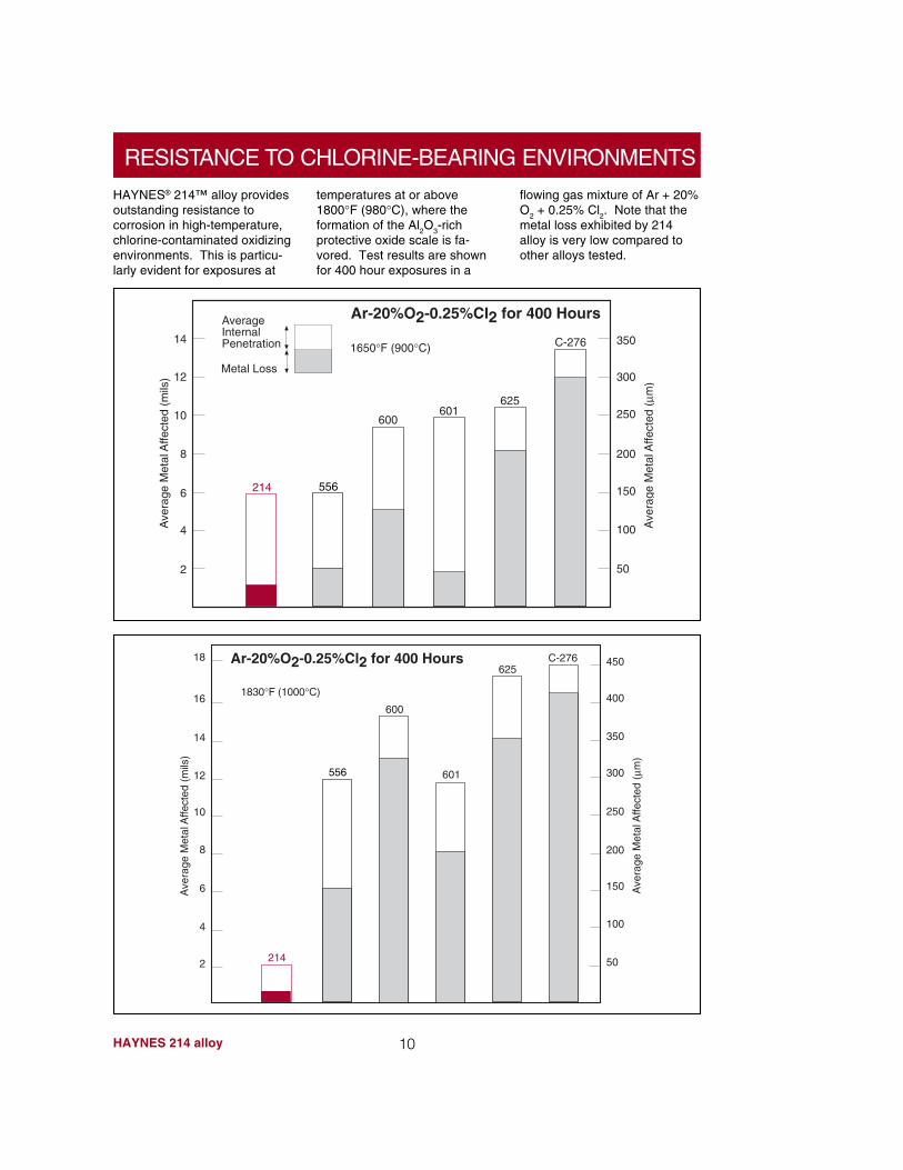
RESISTANCE TO CHLORINE-BEARING ENVIRONMENTS
HAYNES® 214™ alloy providesoutstanding resistance tocorrosion in high-temperature,chlorine-contaminated oxidizingenvironments. This is particu-larly evident for exposures at
temperatures at or above1800°F (980°C), where theformation of the Al
2O
3-rich
protective oxide scale is fa-vored. Test results are shownfor 400 hour exposures in a
flowing gas mixture of Ar + 20%O
2 + 0.25% Cl
2. Note that the
metal loss exhibited by 214alloy is very low compared toother alloys tested.
C-276
625601
600
556214
1650°F (900°C)
AverageInternalPenetration
Metal Loss
14
12
10
8
6
4
2
Ar-20%O2-0.25%Cl2 for 400 Hours
Ave
rage
Met
al A
ffect
ed (
mils
)
Ave
rage
Met
al A
ffect
ed (
µm)
350
300
250
200
150
100
50
C-276625
601
600
556
214
1830°F (1000°C)
14
12
10
8
6
4
2
Ar-20%O2-0.25%Cl2 for 400 Hours
Ave
rage
Met
al A
ffect
ed (
mils
)
Ave
rage
Met
al A
ffect
ed (
µm)
350
300
250
200
150
100
50
16
18
400
450
11 HAYNES 214 alloy
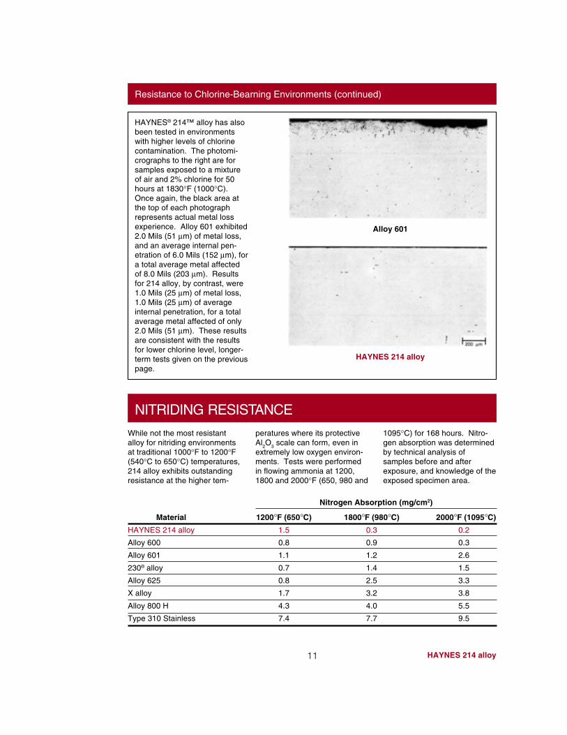
Resistance to Chlorine-Bearning Environments (continued)
Alloy 601
HAYNES 214 alloy
NITRIDING RESISTANCE
While not the most resistantalloy for nitriding environmentsat traditional 1000°F to 1200°F(540°C to 650°C) temperatures,214 alloy exhibits outstandingresistance at the higher tem-
peratures where its protectiveAl
2O
3 scale can form, even in
extremely low oxygen environ-ments. Tests were performedin flowing ammonia at 1200,1800 and 2000°F (650, 980 and
1095°C) for 168 hours. Nitro-gen absorption was determinedby technical analysis ofsamples before and afterexposure, and knowledge of theexposed specimen area.
HAYNES® 214™ alloy has alsobeen tested in environmentswith higher levels of chlorinecontamination. The photomi-crographs to the right are forsamples exposed to a mixtureof air and 2% chlorine for 50hours at 1830°F (1000°C).Once again, the black area atthe top of each photographrepresents actual metal lossexperience. Alloy 601 exhibited2.0 Mils (51 µm) of metal loss,and an average internal pen-etration of 6.0 Mils (152 µm), fora total average metal affectedof 8.0 Mils (203 µm). Resultsfor 214 alloy, by contrast, were1.0 Mils (25 µm) of metal loss,1.0 Mils (25 µm) of averageinternal penetration, for a totalaverage metal affected of only2.0 Mils (51 µm). These resultsare consistent with the resultsfor lower chlorine level, longer-term tests given on the previouspage.
Material
HAYNES 214 alloy
Alloy 600
Alloy 601
230® alloy
Alloy 625
X alloy
Alloy 800 H
Type 310 Stainless
2000°F (1095°C)
0.2
0.3
2.6
1.5
3.3
3.8
5.5
9.5
1800°F (980°C)
0.3
0.9
1.2
1.4
2.5
3.2
4.0
7.7
1200°F (650°C)
1.5
0.8
1.1
0.7
0.8
1.7
4.3
7.4
Nitrogen Absorption (mg/cm2)
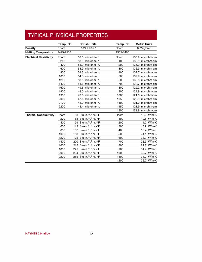
Electrical Resistivity Room 53.5 microhm-in. Room 135.9 microhm-cm200 53.9 microhm-in. 100 136.9 microhm-cm400 53.9 microhm-in. 200 136.9 microhm-cm600 53.9 microhm-in. 300 136.9 microhm-cm800 54.3 microhm-in. 400 137.7 microhm-cm
1000 54.3 microhm-in. 500 137.9 microhm-cm1200 53.5 microhm-in. 600 136.8 microhm-cm1400 51.6 microhm-in. 700 133.7 microhm-cm1600 49.6 microhm-in. 800 129.2 microhm-cm1800 48.0 microhm-in. 900 124.9 microhm-cm1900 47.6 microhm-in. 1000 121.6 microhm-cm2000 47.6 microhm-in. 1050 120.9 microhm-cm2100 48.0 microhm-in. 1100 121.0 microhm-cm2200 48.4 microhm-in. 1150 121.9 microhm-cm
1200 122.9 microhm-cm
12HAYNES 214 alloy
TYPICAL PHYSICAL PROPERTIES
Temp., °F British Units Temp., °C Metric UnitsDensity Room 0.291 lb/in.3 Room 8.05 g/cm.3
Melting Temperature 2475-2550 1355-1400
Thermal Conductivity Room 83 Btu-in./ft.2 hr.-°F Room 12.0 W/m-K200 88 Btu-in./ft.2 hr.-°F 100 12.8 W/m-K400 99 Btu-in./ft.2 hr.-°F 200 14.2 W/m-K600 112 Btu-in./ft.2 hr.-°F 300 15.9 W/m-K800 132 Btu-in./ft.2 hr.-°F 400 18.4 W/m-K
1000 153 Btu-in./ft.2 hr.-°F 500 21.1 W/m-K1200 175 Btu-in./ft.2 hr.-°F 600 23.9 W/m-K1400 200 Btu-in./ft.2 hr.-°F 700 26.9 W/m-K1600 215 Btu-in./ft.2 hr.-°F 800 29.7 W/m-K1800 225 Btu-in./ft.2 hr.-°F 900 31.4 W/m-K2000 234 Btu-in./ft.2 hr.-°F 1000 32.7 W/m-K2200 255 Btu-in./ft.2 hr.-°F 1100 34.0 W/m-K
1200 36.7 W/m-K
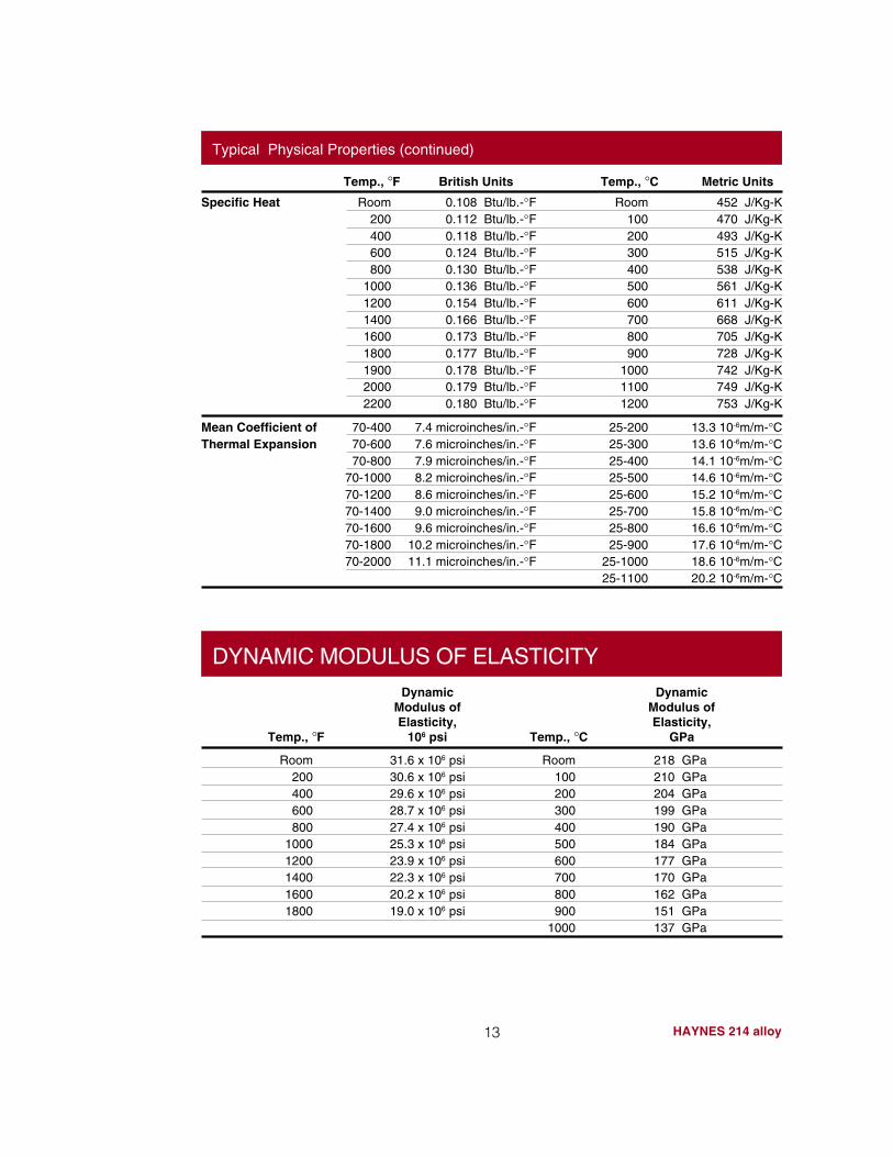
Mean Coefficient of 70-400 7.4 microinches/in.-°F 25-200 13.3 10-6m/m-°CThermal Expansion 70-600 7.6 microinches/in.-°F 25-300 13.6 10-6m/m-°C
70-800 7.9 microinches/in.-°F 25-400 14.1 10-6m/m-°C70-1000 8.2 microinches/in.-°F 25-500 14.6 10-6m/m-°C70-1200 8.6 microinches/in.-°F 25-600 15.2 10-6m/m-°C70-1400 9.0 microinches/in.-°F 25-700 15.8 10-6m/m-°C70-1600 9.6 microinches/in.-°F 25-800 16.6 10-6m/m-°C70-1800 10.2 microinches/in.-°F 25-900 17.6 10-6m/m-°C70-2000 11.1 microinches/in.-°F 25-1000 18.6 10-6m/m-°C
25-1100 20.2 10-6m/m-°C
13 HAYNES 214 alloy
Typical Physical Properties (continued)
Specific Heat Room 0.108 Btu/lb.-°F Room 452 J/Kg-K200 0.112 Btu/lb.-°F 100 470 J/Kg-K400 0.118 Btu/lb.-°F 200 493 J/Kg-K600 0.124 Btu/lb.-°F 300 515 J/Kg-K800 0.130 Btu/lb.-°F 400 538 J/Kg-K
1000 0.136 Btu/lb.-°F 500 561 J/Kg-K1200 0.154 Btu/lb.-°F 600 611 J/Kg-K1400 0.166 Btu/lb.-°F 700 668 J/Kg-K1600 0.173 Btu/lb.-°F 800 705 J/Kg-K1800 0.177 Btu/lb.-°F 900 728 J/Kg-K1900 0.178 Btu/lb.-°F 1000 742 J/Kg-K2000 0.179 Btu/lb.-°F 1100 749 J/Kg-K2200 0.180 Btu/lb.-°F 1200 753 J/Kg-K
Temp., °F British Units Temp., °C Metric Units
Room 31.6 x 10⁶ psi Room 218 GPa200 30.6 x 10⁶ psi 100 210 GPa400 29.6 x 10⁶ psi 200 204 GPa600 28.7 x 10⁶ psi 300 199 GPa800 27.4 x 10⁶ psi 400 190 GPa
1000 25.3 x 10⁶ psi 500 184 GPa1200 23.9 x 10⁶ psi 600 177 GPa1400 22.3 x 10⁶ psi 700 170 GPa1600 20.2 x 10⁶ psi 800 162 GPa1800 19.0 x 10⁶ psi 900 151 GPa
1000 137 GPa
Dynamic DynamicModulus of Modulus ofElasticity, Elasticity,
Temp., °F 106 psi Temp., °C GPa
DYNAMIC MODULUS OF ELASTICITY
14HAYNES 214 alloy
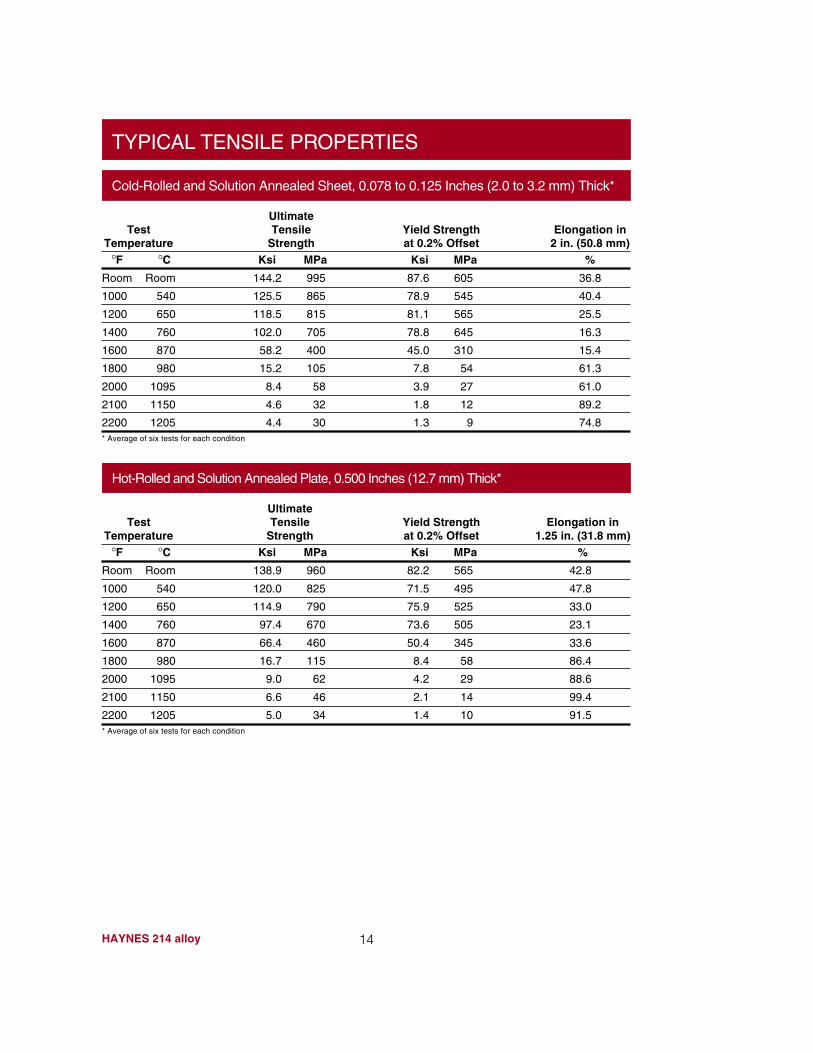
TYPICAL TENSILE PROPERTIES
Cold-Rolled and Solution Annealed Sheet, 0.078 to 0.125 Inches (2.0 to 3.2 mm) Thick*
Elongation in2 in. (50.8 mm)
%
36.8
40.4
25.5
16.3
15.4
61.3
61.0
89.2
74.8
TestTemperature
°F °CRoom Room
1000 540
1200 650
1400 760
1600 870
1800 980
2000 1095
2100 1150
2200 1205
Yield Strengthat 0.2% Offset
Ksi MPa
87.6 605
78.9 545
81.1 565
78.8 645
45.0 310
7.8 54
3.9 27
1.8 12
1.3 9
UltimateTensile
StrengthKsi MPa
144.2 995
125.5 865
118.5 815
102.0 705
58.2 400
15.2 105
8.4 58
4.6 32
4.4 30* Average of six tests for each condition
Hot-Rolled and Solution Annealed Plate, 0.500 Inches (12.7 mm) Thick*
Elongation in1.25 in. (31.8 mm)
%
42.8
47.8
33.0
23.1
33.6
86.4
88.6
99.4
91.5
TestTemperature
°F °CRoom Room
1000 540
1200 650
1400 760
1600 870
1800 980
2000 1095
2100 1150
2200 1205
Yield Strengthat 0.2% Offset
Ksi MPa
82.2 565
71.5 495
75.9 525
73.6 505
50.4 345
8.4 58
4.2 29
2.1 14
1.4 10
UltimateTensile
StrengthKsi MPa
138.9 960
120.0 825
114.9 790
97.4 670
66.4 460
16.7 115
9.0 62
6.6 46
5.0 34* Average of six tests for each condition
15 HAYNES 214 alloy
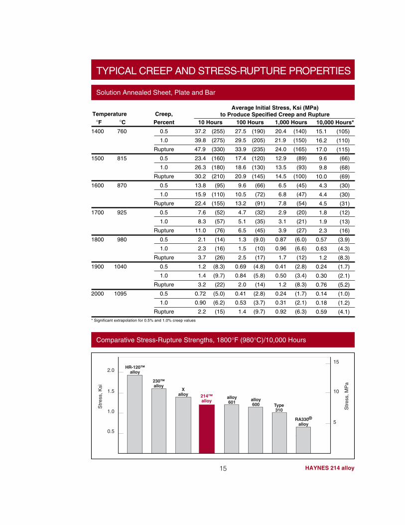
TYPICAL CREEP AND STRESS-RUPTURE PROPERTIES
Temperature°F °C
1400 760
1500 815
1600 870
1700 925
1800 980
1900 1040
2000 1095
Creep,Percent
0.5
1.0
Rupture
0.5
1.0
Rupture
0.5
1.0
Rupture
0.5
1.0
Rupture
0.5
1.0
Rupture
0.5
1.0
Rupture
0.5
1.0
Rupture
10 Hours
37.2 (255)
39.8 (275)
47.9 (330)
23.4 (160)
26.3 (180)
30.2 (210)
13.8 (95)
15.9 (110)
22.4 (155)
7.6 (52)
8.3 (57)
11.0 (76)
2.1 (14)
2.3 (16)
3.7 (26)
1.2 (8.3)
1.4 (9.7)
3.2 (22)
0.72 (5.0)
0.90 (6.2)
2.2 (15)
100 Hours
27.5 (190)
29.5 (205)
33.9 (235)
17.4 (120)
18.6 (130)
20.9 (145)
9.6 (66)
10.5 (72)
13.2 (91)
4.7 (32)
5.1 (35)
6.5 (45)
1.3 (9.0)
1.5 (10)
2.5 (17)
0.69 (4.8)
0.84 (5.8)
2.0 (14)
0.41 (2.8)
0.53 (3.7)
1.4 (9.7)
1,000 Hours
20.4 (140)
21.9 (150)
24.0 (165)
12.9 (89)
13.5 (93)
14.5 (100)
6.5 (45)
6.8 (47)
7.8 (54)
2.9 (20)
3.1 (21)
3.9 (27)
0.87 (6.0)
0.96 (6.6)
1.7 (12)
0.41 (2.8)
0.50 (3.4)
1.2 (8.3)
0.24 (1.7)
0.31 (2.1)
0.92 (6.3)
10,000 Hours*
15.1 (105)
16.2 (110)
17.0 (115)
9.6 (66)
9.8 (68)
10.0 (69)
4.3 (30)
4.4 (30)
4.5 (31)
1.8 (12)
1.9 (13)
2.3 (16)
0.57 (3.9)
0.63 (4.3)
1.2 (8.3)
0.24 (1.7)
0.30 (2.1)
0.76 (5.2)
0.14 (1.0)
0.18 (1.2)
0.59 (4.1)
Average Initial Stress, Ksi (MPa)to Produce Specified Creep and Rupture
Solution Annealed Sheet, Plate and Bar
* Significant extrapolation for 0.5% and 1.0% creep values
Comparative Stress-Rupture Strengths, 1800°F (980°C)/10,000 Hours
HR-120™alloy
214™alloy
0.5
Str
ess,
Ksi
Str
ess,
MP
a
15
10
50
1.0
1.5
2.0
5
230™alloy
Xalloy
alloy601 alloy
600 Type310
RA330®alloy
HAYNES 214 alloy
THERMAL STABILITY
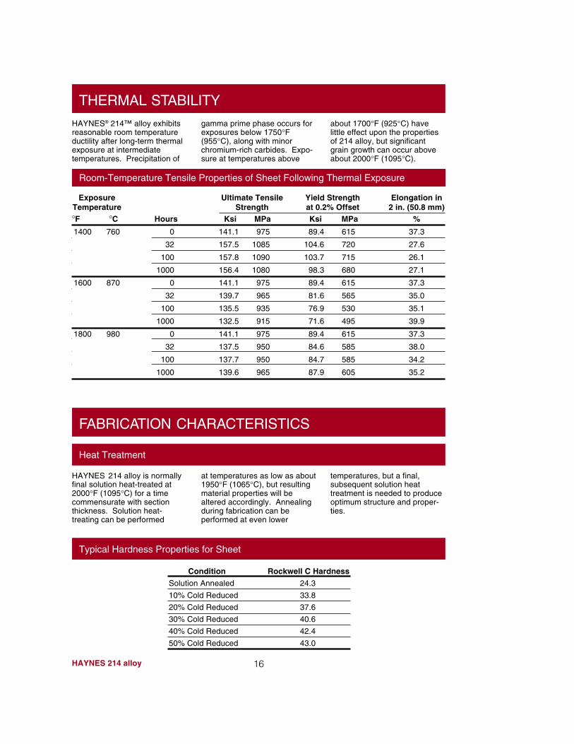
gamma prime phase occurs forexposures below 1750°F(955°C), along with minorchromium-rich carbides. Expo-sure at temperatures above
about 1700°F (925°C) havelittle effect upon the propertiesof 214 alloy, but significantgrain growth can occur aboveabout 2000°F (1095°C).
HAYNES® 214™ alloy exhibitsreasonable room temperatureductility after long-term thermalexposure at intermediatetemperatures. Precipitation of
Room-Temperature Tensile Properties of Sheet Following Thermal Exposure
Elongation in2 in. (50.8 mm)
%
37.3
27.6
26.1
27.1
37.3
35.0
35.1
39.9
37.3
38.0
34.2
35.2
Ultimate TensileStrength
Ksi MPa
141.1 975
157.5 1085
157.8 1090
156.4 1080
141.1 975
139.7 965
135.5 935
132.5 915
141.1 975
137.5 950
137.7 950
139.6 965
Hours
0
32
100
1000
0
32
100
1000
0
32
100
1000
Yield Strengthat 0.2% OffsetKsi MPa
89.4 615
104.6 720
103.7 715
98.3 680
89.4 615
81.6 565
76.9 530
71.6 495
89.4 615
84.6 585
84.7 585
87.9 605
ExposureTemperature°F °C1400 760
1600 870
1800 980
FABRICATION CHARACTERISTICS
Heat Treatment
at temperatures as low as about1950°F (1065°C), but resultingmaterial properties will bealtered accordingly. Annealingduring fabrication can beperformed at even lower
temperatures, but a final,subsequent solution heattreatment is needed to produceoptimum structure and proper-ties.
HAYNES 214 alloy is normallyfinal solution heat-treated at2000°F (1095°C) for a timecommensurate with sectionthickness. Solution heat-treating can be performed
Typical Hardness Properties for Sheet
16
Condition
Solution Annealed
10% Cold Reduced
20% Cold Reduced
30% Cold Reduced
40% Cold Reduced
50% Cold Reduced
Rockwell C Hardness
24.3
33.8
37.6
40.6
42.4
43.0
17 HAYNES 214 alloy
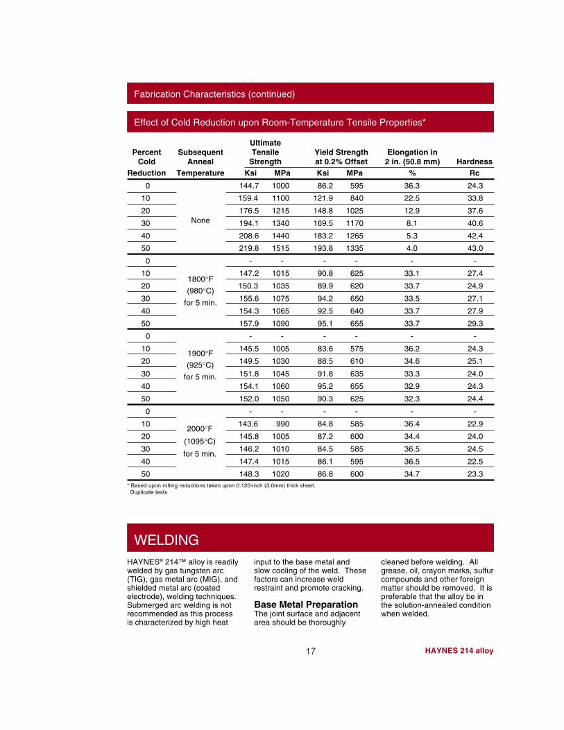
Fabrication Characteristics (continued)
Effect of Cold Reduction upon Room-Temperature Tensile Properties*
PercentCold
Reduction
0
10
20
30
40
50
0
10
20
30
40
50
0
10
20
30
40
50
0
10
20
30
40
50* Based upon rolling reductions taken upon 0.120-inch (3.0mm) thick sheet. Duplicate tests
HAYNES® 214™ alloy is readilywelded by gas tungsten arc(TIG), gas metal arc (MIG), andshielded metal arc (coatedelectrode), welding techniques.Submerged arc welding is notrecommended as this processis characterized by high heat
WELDINGinput to the base metal andslow cooling of the weld. Thesefactors can increase weldrestraint and promote cracking.
Base Metal PreparationThe joint surface and adjacentarea should be thoroughly
cleaned before welding. Allgrease, oil, crayon marks, sulfurcompounds and other foreignmatter should be removed. It ispreferable that the alloy be inthe solution-annealed conditionwhen welded.
HardnessRc
24.3
33.8
37.6
40.6
42.4
43.0
-
27.4
24.9
27.1
27.9
29.3
-
24.3
25.1
24.0
24.3
24.4
-
22.9
24.0
24.5
22.5
23.3
Elongation in2 in. (50.8 mm)
%
36.3
22.5
12.9
8.1
5.3
4.0
-
33.1
33.7
33.5
33.7
33.7
-
36.2
34.6
33.3
32.9
32.3
-
36.4
34.4
36.5
36.5
34.7
Yield Strengthat 0.2% OffsetKsi MPa
86.2 595
121.9 840
148.8 1025
169.5 1170
183.2 1265
193.8 1335
- -
90.8 625
89.9 620
94.2 650
92.5 640
95.1 655
- -
83.6 575
88.5 610
91.8 635
95.2 655
90.3 625
- -
84.8 585
87.2 600
84.5 585
86.1 595
86.8 600
UltimateTensile
StrengthKsi MPa
144.7 1000
159.4 1100
176.5 1215
194.1 1340
208.6 1440
219.8 1515
- -
147.2 1015
150.3 1035
155.6 1075
154.3 1065
157.9 1090
- -
145.5 1005
149.5 1030
151.8 1045
154.1 1060
152.0 1050
- -
143.6 990
145.8 1005
146.2 1010
147.4 1015
148.3 1020
SubsequentAnneal
Temperature
None
1800°F(980°C)
for 5 min.
1900°F(925°C)
for 5 min.
2000°F(1095°C)
for 5 min.
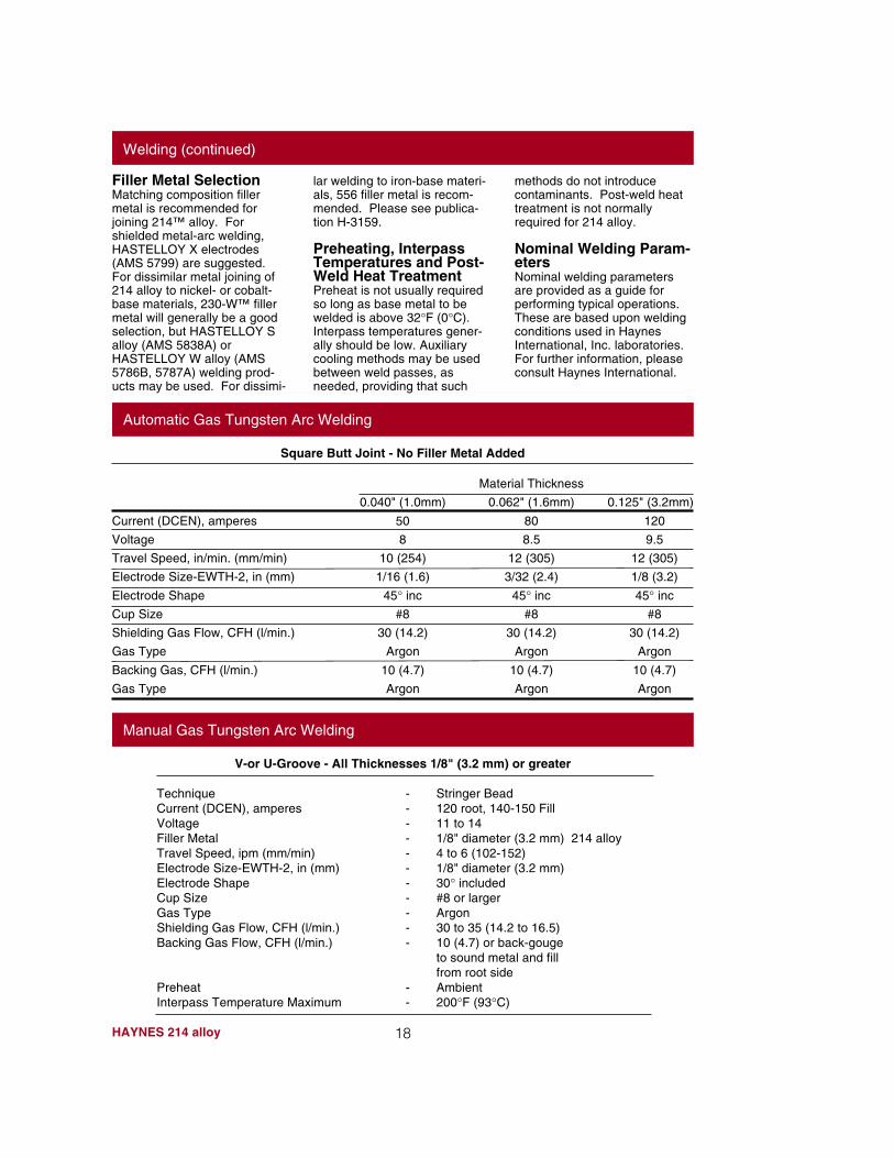
V-or U-Groove - All Thicknesses 1/8" (3.2 mm) or greater
Technique - Stringer BeadCurrent (DCEN), amperes - 120 root, 140-150 FillVoltage - 11 to 14Filler Metal - 1/8" diameter (3.2 mm) 214 alloyTravel Speed, ipm (mm/min) - 4 to 6 (102-152)Electrode Size-EWTH-2, in (mm) - 1/8" diameter (3.2 mm)Electrode Shape - 30° includedCup Size - #8 or largerGas Type - ArgonShielding Gas Flow, CFH (l/min.) - 30 to 35 (14.2 to 16.5)Backing Gas Flow, CFH (l/min.) - 10 (4.7) or back-gouge
to sound metal and fillfrom root side
Preheat - AmbientInterpass Temperature Maximum - 200°F (93°C)
Welding (continued)
Filler Metal SelectionMatching composition fillermetal is recommended forjoining 214™ alloy. Forshielded metal-arc welding,HASTELLOY X electrodes(AMS 5799) are suggested.For dissimilar metal joining of214 alloy to nickel- or cobalt-base materials, 230-W™ fillermetal will generally be a goodselection, but HASTELLOY Salloy (AMS 5838A) orHASTELLOY W alloy (AMS5786B, 5787A) welding prod-ucts may be used. For dissimi-
lar welding to iron-base materi-als, 556 filler metal is recom-mended. Please see publica-tion H-3159.
Preheating, InterpassTemperatures and Post-Weld Heat TreatmentPreheat is not usually requiredso long as base metal to bewelded is above 32°F (0°C).Interpass temperatures gener-ally should be low. Auxiliarycooling methods may be usedbetween weld passes, asneeded, providing that such
methods do not introducecontaminants. Post-weld heattreatment is not normallyrequired for 214 alloy.
Nominal Welding Param-etersNominal welding parametersare provided as a guide forperforming typical operations.These are based upon weldingconditions used in HaynesInternational, Inc. laboratories.For further information, pleaseconsult Haynes International.
Automatic Gas Tungsten Arc Welding
Square Butt Joint - No Filler Metal Added
Material Thickness
0.040" (1.0mm) 0.062" (1.6mm) 0.125" (3.2mm)
Current (DCEN), amperes 50 80 120
Voltage 8 8.5 9.5
Travel Speed, in/min. (mm/min) 10 (254) 12 (305) 12 (305)
Electrode Size-EWTH-2, in (mm) 1/16 (1.6) 3/32 (2.4) 1/8 (3.2)
Electrode Shape 45° inc 45° inc 45° inc
Cup Size #8 #8 #8
Shielding Gas Flow, CFH (l/min.) 30 (14.2) 30 (14.2) 30 (14.2)
Gas Type Argon Argon Argon
Backing Gas, CFH (l/min.) 10 (4.7) 10 (4.7) 10 (4.7)
Gas Type Argon Argon Argon
Manual Gas Tungsten Arc Welding
18HAYNES 214 alloy
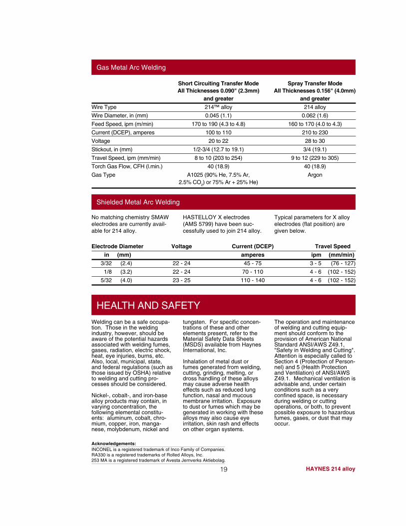
Gas Metal Arc Welding
Short Circuiting Transfer Mode Spray Transfer ModeAll Thicknesses 0.090" (2.3mm) All Thicknesses 0.156" (4.0mm)
and greater and greater
Wire Type 214™ alloy 214 alloy
Wire Diameter, in (mm) 0.045 (1.1) 0.062 (1.6)
Feed Speed, ipm (m/min) 170 to 190 (4.3 to 4.8) 160 to 170 (4.0 to 4.3)
Current (DCEP), amperes 100 to 110 210 to 230
Voltage 20 to 22 28 to 30
Stickout, in (mm) 1/2-3/4 (12.7 to 19.1) 3/4 (19.1)
Travel Speed, ipm (mm/min) 8 to 10 (203 to 254) 9 to 12 (229 to 305)
Torch Gas Flow, CFH (l.min.) 40 (18.9) 40 (18.9)
Gas Type A1025 (90% He, 7.5% Ar, Argon2.5% CO
2) or 75% Ar + 25% He)
Electrode Diameter Voltage Current (DCEP) Travel Speed
in (mm) amperes ipm (mm/min)
3/32 (2.4) 22 - 24 45 - 75 3 - 5 (76 - 127)
1/8 (3.2) 22 - 24 70 - 110 4 - 6 (102 - 152)
5/32 (4.0) 23 - 25 110 - 140 4 - 6 (102 - 152)
Shielded Metal Arc Welding
No matching chemistry SMAWelectrodes are currently avail-able for 214 alloy.
Typical parameters for X alloyelectrodes (flat position) aregiven below.
HASTELLOY X electrodes(AMS 5799) have been suc-cessfully used to join 214 alloy.
HEALTH AND SAFETY
Welding can be a safe occupa-tion. Those in the weldingindustry, however, should beaware of the potential hazardsassociated with welding fumes,gases, radiation, electric shock,heat, eye injuries, burns, etc.Also, local, municipal, state,and federal regulations (such asthose issued by OSHA) relativeto welding and cutting pro-cesses should be considered.
Nickel-, cobalt-, and iron-basealloy products may contain, invarying concentration, thefollowing elemental constitu-ents: aluminum, cobalt, chro-mium, copper, iron, manga-nese, molybdenum, nickel and
tungsten. For specific concen-trations of these and otherelements present, refer to theMaterial Safety Data Sheets(MSDS) available from HaynesInternational, Inc.
Inhalation of metal dust orfumes generated from welding,cutting, grinding, melting, ordross handling of these alloysmay cause adverse healtheffects such as reduced lungfunction, nasal and mucousmembrane irritation. Exposureto dust or fumes which may begenerated in working with thesealloys may also cause eyeirritation, skin rash and effectson other organ systems.
The operation and maintenanceof welding and cutting equip-ment should conform to theprovision of American NationalStandard ANSI/AWS Z49.1,"Safety in Welding and Cutting".Attention is especially called toSection 4 (Protection of Person-nel) and 5 (Health Protectionand Ventilation) of ANSI/AWSZ49.1. Mechanical ventilation isadvisable and, under certainconditions such as a veryconfined space, is necessaryduring welding or cuttingoperations, or both, to preventpossible exposure to hazardousfumes, gases, or dust that mayoccur.
19 HAYNES 214 alloy
Acknowledgements:INCONEL is a registered trademark of Inco Family of Companies.RA330 is a registered trademarks of Rolled Alloys, Inc.253 MA is a registered trademark of Avesta Jernverks Aktiebolag.
For Referral to Authorized Distributors in your area Fax: 1-317-456-6079Printed in U.S.A.
STANDARD PRODUCTS By Brand or Alloy Designation:
B-2, B-3™, C-4, C-22®, C-276, C-2000™, D-205™, G-3, G-30®, G-50®, H-9M™ and N
Corrosion-Wear Resistant Alloy
ULTIMET®
25, R-41, 75, HR-120™, 150, HR-160®, 188, 214™, 230®, 230-W™, 242™, 263, 556™, 625, 718, X-750,MULTIMET® and WASPALOY
Wear-Resistant Alloy
Ti-3Al-2.5V
HASTELLOY Family of Heat-Resistant Alloys
HASTELLOY ® Family of Corrosion-Resistant Alloys
S, W, and X
HAYNES ® Family of Heat-Resistant Alloys
6B
HAYNES Titanium Alloy Tubular
For More Information Contact:
Kokomo, Indiana 46904-90131020 W. Park AvenueP.O. Box 9013Tel: 317-456-6012 800-354-0806FAX: 317-456-6905
Anaheim, California 92806Stadium Plaza1520 South Sinclair StreetTel: 714-978-1775 800-531-0285FAX: 714-978-1743
Arcadia, Louisiana 71001-97013786 Second StreetTel: 318-263-9571 800-648-8823FAX: 318-263-8088
ItalyHaynes International, S.R.L.Viale Brianza, 820127 MilanoTel: 39-2-2614-1331FAX: 39-2-282-8273
SwitzerlandNickel Contor AGHohlstrasse 534CH-8048 ZurichTel: 41-1-434-7080FAX: 41-1-431-8787
EnglandHaynes International, Ltd.P.O. Box 10Parkhouse StreetOpenshawManchester, M11 2ERTel: 44-161-230-7777FAX: 44-161-223-2412
FranceHaynes International, S.A.R.L.Boite Postale 711095054 CERGY PONTOISECedexTel: 33-1-34-48-3100FAX: 33-1-30-37-8022
Windsor, Connecticut 06095430 Hayden Station RoadTel: 860-688-7771 800-426-1963FAX: 860-688-5550
Houston, Texas 77041The Northwood Industrial Park12241 FM 529Tel: 713-937-7597 800-231-4548FAX: 713-937-4596
072596
Properties Data:The data and information in this publication are basedon work conducted principally by Haynes International, Inc.and occasionally supplemented by information from the openliterature, and are believed to be reliable. However, we donot make any warranty or assume any legal liability orresponsibility for its accuracy, completeness or usefulness,nor do we represent that its use would not infringe upon
private rights. Any suggestions as to uses and applicationsfor specific alloys are opinions only and Haynes Interna-tional, Inc. makes no warranty of results to be obtained inany particular situation. For specific concentrations ofelements present in a particular product and a discussion ofthe potential health effects thereof, refer to the MaterialSafety Data Sheet supplied by Haynes International, Inc.
Bar, Billet, Remelt Materials, Plate, Sheet, Strip, Coils, Seamless or Welded Pipe & Tubing,Welding Wire and Coated Electrodes
Standard Forms: