Embed Size (px)
Citation preview

Advances in Solid State Joining of Haynes 230 High Temperature Alloy
R. Jeffrey Ding, NASA-Marshall Space Flight Center, Huntsville, USA
Judy Schneider, Mississippi State University, Mississippi State, USA
SYNOPSIS
Three solid state joining processes were investigated for the joining of a nickel based superalloy, Haynes 230. These solid state welding processes included: conventional FSW (C-FSW), hybrid FSW (H-FSW), and, thermal stir welding (TSW). Initial welds using C-FSW process resulted in severe pin tool degradation due to excessive heat generation and were thus abandoned. The TSW process was used for further weld trials and, like the C-FSW process, was abandoned due to excessive heat. The H-FSW process was successfully used for the duration of weld trials. The three weld processes used will be discussed along with the corresponding metallographical results.
INTRODUCTION
To improve the efficiency of propulsion systems, a non cooled, thin walled rocket extension nozzle in the shape of a curved shell contains and shapes the exit flow. For this application, balancing weight limitations with high-temperature capability requires a stiffened thin-walled, structure that can accommodate the pressures, dynamic loading, and vibrational stresses associated with the high acoustic and fluctuating pressures from the high temperaturecombustion and supersonic gas stream. The pressures and vibrational loading drives the need for stress rupture capable and fatigue resistant materials. In turn, the selection of suitable materials challenges the selection of suitable fabrication processes.
A common fabrication method used to form the complex curvature is to start with a flat panel that is rolled and welded to form a cylinder that is subsequently drawn or spun formed over a mandrel to form the thin-wall curved shape of the nozzle. After forming, chemical milling is used to obtain the final wall thickness with integral stiffeners. This requires selection of a suitable joining technique that will be amenable to the various fabrication processes.
Thus the demands for the material selection in the fabrication of nozzle extensions arerigorous requiring high temperature properties in addition to fabricability. Haynes 230 alloy is a relatively new nickel-based super alloy designed for high-temperature components in gas turbines, rocket engines, chemical processing, and industrial heating industries [1]. The alloy is useful over this range of applications due to a combination of good high-temperature strength and corrosion resistance, thermal stability, and fabricability [2].
In fusion welding of Haynes 230 alloy hot or solidification cracking and microfissuring issueshave been reported in the microstructure, particularly in heavier section plate products (>6 mm) [3]. In addition, concerns remain regarding the uniformity of chemical milling over the microstructure of a coarse grained, fusion welded joint. During launch, the nozzle extension is subjected to combined high pressure and vibration stress modes. These conditions require good stress-rupture properties and high cycle fatigue capability not usually
https://ntrs.nasa.gov/search.jsp?R=20100022119 2018-06-24T18:46:39+00:00Z

associated with fusion welding of nickel based super alloys. Avoiding fusion welding issues can be mitigated with the use of solid-state welding methods for joining of Haynes 230. In this study, three solid-state welding processes were evaluated as an alternative processfor joining of the Haynes 230 alloy.
BODY OF PAPERConventional (C)-FSW
C-FSW is a solid state welding process that is well known within the welding sectors of the world’s industrialized countries. Figure 1 illustrates this process which uses a backing anvil to react against the plunge force of the tool as it stirs the plasticized metal together to form a seam. In this process, the tool generates the heat, stirring and confinement of the plasticized metal. As numerous manuscripts have been published on this topic [4], it will not be described in further detail in the scope of this paper.
Figure 1. Schematic of conventional friction stir welding process
Thermal stir welding (TSW)
TSWing [5] is a solid state weld process similar to FSW in that the weld material is heated into a plastic state and subsequently stirred using a stir rod as illustrated in Figure 2. Unlike FSW, TSW decouples the heating, stirring and forging elements of the process and allows each to be independently controlled. During the TSW process, the work piece is heated to the desired temperature using a specially designed induction coil. Once the desired temperature is reached, the work piece travels through an independently controlled rotating stir rod. A spindle motor controls the rotation of the stir rod which protrudes through upper and lower non-rotating containment plates and is finally captured in a lower fitting beneath the lower containment plate. The work piece travels between the upper and lower containment plates and is “squeezed” with independently controlled forging pressures to assure weld metal consolidation. The containment plates also prevent plastic material from spewing out during the stirring. The independent control of the heating, stirring and forging elements allow for total thermal control of the process. For instance, if a nugget temperature of 760° C is desired in 13 mm thick CP titanium during the stir weld process, the induction coil temperature, stir rod RPM, travel rate, and forging pressures can all be independently controlled, in concert, to assure a specific temperature is maintained in the weld nugget zone – real time.

Figure 2. Schematic of thermal stir weld process.
Hybrid (H)-FSW
H-FSW is a welding technique that first preheats the weld joint work piece to a desired temperature before the C-FSW pin tool plunges into the weld joint for subsequent stirring as illustrated in Figure 3. The lower containment plate provides a floating backing anvil for the metal to react against.
Figure 3. Schematic of hybrid friction stir welding process.
Solid state joining equipment.
The solid state joining equipment used for these trials, shown in Figure 4, is very versatile and capable of adapting to the modes of operation evaluated in this study. During the course of conducting the joining studies, difficulties in managing the heat were identified that resulted in a series of major modifications to the solid state joining equipment. In particularthe studies indicated that joining of heat resistant alloys at the higher temperatures required independent cooling for the spindle, stir rod and containment plates. It was found that the solid state joining of Hayes 230 generated excessive heat when using the C-FSW and TSW modes of operation. Additional upgrades are planned for integration of high powered ultrasonics (HPU) with the containment plates and stir rod. This will provide the additional capabilities of ultrasonic stir welding [6] as well as ultrasonically assisted TSW [5].

Figure 4. Solid state joining equipment at NASA-MSFC. This equipment readily adapts to all variations of the friction stir welding process.
Haynes 230
HAYNES 230 is an industrial grade, heat-resistant alloy which resists environmental corrosion allowing for continuous service in air up to 1150°C [7]. The alloy is based on the
Ni-Cr-W system and is solution and carbide strengthened [7]. Table I summarizes the major elemental composition and the as-received microstructure is shown in Figure 5. The microstructure is comprised of approximately 35 m grains with dispersed tungsten rich carbide particles. In the solution annealed state, a relatively small amount of the tungsten rich carbide is reported as the primary phase with increased distributions, or secondaryphase, forming after exposure to elevated temperatures [7]. The recommended hot working temperature is 1175° C with a solid solution temperature range of 1120 – 1230° C [7].
Table I. Major alloying elements in the nickel based Haynes 230 alloy [7]. Element Min (wt. %) Max (wt. %)
Chromium 20.00 24.00
Tungsten 13.00 15.00
Figure 5. Photomicrograph of as received Haynes 230. The grain size is approximately 35 m with 0.2% by volume tungsten rich particles.
Experimental Procedure
A 0.64 cm thick plate of Haynes 230 was received and cut into 20 x 60 cm panels to be used in evaluating the various solid state joining techniques. Panels were instrumented with thermocouples to document the resulting temperatures around the stir rod and uniformity along the weld and through the material. All joints were made with an argon purge. After the solid state joining process was completed, the panels were sectioned for metallographic characterization to access the quality of the weld and document final grain size and grain morphology.
Selection of the solid state joining process is also dependent on selection of a material for the stir rod that can withstand the elevated temperatures. A 13 mm stir rod design was used with the various tungsten alloys summarized in Table II. Figure 6 shows the configuration of the TSW and H-FSW tools.
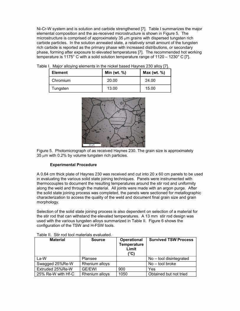
Table II. Stir rod tool materials evaluated.Material Source Operational
TemperatureLimit(oC)
Survived TSW Process
La-W Plansee No – tool disintegratedSwagged 25%Re-W Rhenium alloys No – tool brokeExtruded 25%Re-W GE/EWI 900 Yes25% Re-W with Hf-C Rhenium alloys 1050 Obtained but not tried

(a) (b)Figure 6. Tooling configuration for the solid state joining equipment: (a) TSW stir tool mounted in upper containment plate and (b) H-FSW stir rod with rotating shoulder.
To obtain complimentary data to support selection of TSWing temperatures, the Haynes 230 was machined into dog-bone tensile coupons and tested in uni-axial tension at elevated temperatures. Tests were run over the temperature range of 900-1200° C in 100 degree increments with 3 tests conducted at each temperature.
Results and Discussion
A review of the literature guided the selection of temperature ranges for solid state joiningprocesses. Aluminum alloys are generally FSWed within the range of 0.8 to 0.9 times the absolute melting temperature [4, 8-13]. In comparison, alloys such as Ti are FSWed as low as 0.6 times the absolute melting temperature to avoid phase transformations [14-17]. Additionally, higher melting temperature materials might be welded at lower temperatures to ensure weld tool survivability. Using this data as a guide, the range of applicable solid state joining temperatures for Haynes 230 is summarized in Table III.
Table III. Temperature ranges applicable for solid state joining of Haynes 230. Tmp(°C)
0.6*Tmp(°C)
0.7*Tmp(°C)
0.8*Tmp(°C)
0.9*Tmp(°C)
1290-1375 665-716 821-881 977-1045 1134-1210
Results from the tensile testing of the Haynes 230 alloy are shown in Figure 7. At temperatures above 1000° C, the yield strength approaches the ultimate tensile strength. This range is desirable for steady state flow stress during the solid state joining process.

Figure 7. Effect of temperature on the strength of Haynes 230.
Although the weld panels were instrumented with thermocouples, a more precise temperature could be obtained by post weld hardness measurements. Since the carbide strengthening of Haynes 230 is affected by processing temperatures, hardness tests were used to document the temperature of the weld metal. To infer the solid state joiningtemperature, Table IV lists the hardness values obtained from the tensile specimens. The hardness values were found to be on the border between Rockwell B (HRB) and Rockwell C (HRC).
Table IV. Hardness values from tensile specimens.
In the initial C-FSW trials, high stir rod rotations were required to plasticize the workpiece. Figure 8 shows a resulting panel from the C-FSW studies. Corresponding processing parameters were stir rod rotation of 700 RPM, travel rate of 51 mm/min, and a z-axis forging force of 30 kN. As can be observed in Figure 8a, these excessive temperatures resulting in tool mushrooming. Similar results were obtained with the equipment configured for TSWing using an induction coil.
(a) (b)
Figure 8. Initial C-FSWs of Haynes 230 showing. (a) condition of overheated stir rod and (b) the corresponding weld panel.
Next the equipment was modified for H-FSWing by adding an induction coil to the solid state joining equipment. The initial H-FSW parameters targeted 980° C for the weld metal. In addition to the induction coil setting, process parameters of 25 mm/min travel, stir rod rotation of 325 RPM, and a z-axis forging force of 22 kN were selected. Figure 9 shows the resulting weld panel. At these process parameters, the swagged Re-W tool broke due to excessive load. Although the corresponding macrograph of the weld shows a large
Tensile Specimen HRC HRBRT 36.4 + 2.4
900º C 23.3 + 3.51000º C 18.2 + 4.71100º C 88.5 + 6.41200º C 77.4 + 10.8
weld direction

wormhole, the nugget material exhibits refined grains typical of the solid state joining process.
(a) (b)
Figure 9. First H-FSW panel. (a) Although problems were encountered with tooling material used resulting in tool breakage shown by red arrow in the plan view of H-FSW SN 10-22-09-D. (b) Metallographic inspection revealed refined grains in the weld nugget.
To reduce the heat input, the targeted temperature range was lowered to 870° C. To allow for the deformational heating, the induction coil preheat was set at 600° C to soften the metal prior to stirring and accommodate the contributions of deformational heating. The tool RPM was reduced in weld 10-22-09 D from 350 RPM to values in the range of 200-250 RPM. Based on post weld hardness values, subsequent welds at 240 RPM (SN 002) and 250 RPM (SN 003) were at approximately 900° C.
In welds, 001 and 002, initial trenching was observed as can be observed in Figure 10.
The macrostructure of weld SN 001 is shown in Figure 11 revealing a slight wormhole and the lack of complete penetration of the pin tool during stirring. Post weld inspection revealed prior damage to the backing anvil contributing to this defect. Thus during the weld, the plunge loads caused the material to bulge on the root side reducing the force the shoulder maintains during stirring and forging the weld zone, resulting in the wormhole.
Moving the weld panel to an undamaged region of the anvil, coupled with welding at slightly higher temperatures resulted in improved appearance of SN -003. The weld trial shown in Figure 10 shows the successful progression in stir-weld capability and demonstrates the feasibility of joining this material by stir-welding methods. The weld parameters are summarized in Table V. Metallurgical analysis of the last two stir welds, SN 002 and SN 003 are shown in Figure 12. Shown in Figure 13 are radiographs of the last two welds: SN 002 and SN 003. Noteworthy is the lack of a wormhole in SN 003. It should also be noted that there is no evidence of tool wear in the radiograph shown in Figure 13 of SN003.
weld direction

(a) *(b) (c)
Figure 10 - Photographs of the plan views of the Haynes 230 H-FSWs for SN 001 (a), SN 002 (b), and SN 003 (c).
Table V. Summary of H-FSWs process parameters.
To evaluate the weld temperature, hardness values from the H-FSWs are summarized in Table VI. The estimated temperature is obtained with the Table IV correlations.
Table VI. Hardness values for H-FSW welds.
Weld SN Coil Temperature
(oC)
RPM Travel (mm/min)
Plunge Force(kN)
Tilt angle(degrees)
001 600 220-240 25 31 2002 600 240 25 31 2003 600 250 25 33 1.5
TSW ID HRC HRB Est. Temperature
(o C)10-22-09 D AS 98 105010-22-09 D RS 95 1050
001 AS 30 101 850001 RS 30 101 850002 AS 21 950002 RS 26 850003 AS 23 900003 RS 23 900

Figure 11 - Macrostructure of Haynes TSW SN 001 showing regions of refined grains.
Figure 12. The macrostructure and microstructure of the H-FSWs.

Figure 13. X-ray radiographs of the H-FSWs. No evidenced of tool wear is observed in either weld. SN 002 shows evidence of a wormhole while SN 003 shows a fully consolidated joint.
Summary
In all successful welds of the Haynes 230 alloy, use of the induction coil was required. Various induction coil temperatures were evaluated with a temperature of 600oC providing the proper heat to soften the material without degradation and ensure survivability of the stir rod. Based on tensile test results, an overall solid state temperature in the range of 800-1000º C is recommended. Setting the induction coil at 600oC pre-softens the weld material while providing for accommodation of the additional deformational heating.
The hardness profile across the SN003 weld was consistent on the AS and RS sides with nugget hardness values slightly higher (HRB =30). Uniform hardness values across the weld nugget are favorable for subsequent forming operations by minimizing occurrence of localized thinning.
To better manage the thermal properties, the containment plates were modified for active cooling. To alleviate heat build up in longer welds, it is recommended to actively cool the tool spindle also. Efforts are on-going to make this modification to the existing solid state joining equipment.
Acknowledgements
References
1) H-2060D, High Temperature Tech Brief, Pub. Haynes International, Inc., 2009.
2) H-3000H, Haynes 230 Alloy Tech Brief, Haynes International, Inc., 2007.
3) Ernst, S.C., “Weldability studies of Haynes 230 alloy,” Welding Res. Supplement, p. 80s-89s, 1994.
4) Mishra, R.S., Ma, Z.Y., “Friction stir welding and processing,” Mat. Sci. & Engr. R., Vol. 50, p. 1-78, 2005.
5) Thermal Stir Welding (TSW), Patent Pending year?, R.J. Ding, NASA-MSFC.

6) Ultrasonic Stir Welding (USW), U.S. patent # 7,568,608.
7) Tawancy, H.M., et al., “Development of a new nickel-base superalloy,” J. Metals, Vol. 36, No. 9, p. 58-62, 1984.
8) Rhodes, C.G. et al. "Effects of Friction Stir Welding on Microstructure of 7075 Aluminum," Scripta Mat., Vol. 36, p. 69-75, 1997.
9) Liu, G. et al. "Microstructural Aspects of the Friction-Stir Welding of 6061-T6 Aluminum," Scripta Mat., Vol. 37, p. 355-361, 1997.
10) Murr, L.E. et al. "A TEM Study of Precipitation and related microstructures in Friction-Stir-Welded 6061 Aluminum," J. Mat. Sci., Vol. 33, p. 1243-1251, 1998.
11) Sato, Y.S. et al. "Microstructural Evolution of 6063 Aluminum during Friction-Stir Welding," Metall. & Mat. Trans. A, Vol. 30A, p. 2429-2437, 1999.
12) Kwon, Y.J., N. Saito, I. Shigematsu. "Friction Stir Process as a New Manufacturing Technique of Ultrafine Grained Aluminum Alloy," J. Mat. Sci. Letters, Vol. 21, p. 1473-1476, 2002.
13) Mahoney, M.W. et al. "Properties of Friction-Stir-Welded 7075 T651 Aluminum," Metall. & Mat. Trans. A, Vol. 29A, p. 1955-1964, 1998.
14) Lienert, T.J., et al., “Friction Stir Welding of Ti-6Al-4V,” Proc. of Joining of Advanced and Specialty Materials, ASM International, St. Louis, MO, October 2000.
15) Lutjering, G., Williams, J., Titanium, Pub. Springer- Verlag, Berlin, 2003.
16) Juhas, M.C., et al., “Microstructural Evolution in Ti Alloy Friction Stir Welds,” Proc. of 2nd International Symposium on Friction Stir Welding, Gothenberg, Sweden, June 2000.
17) Zhang, Y., et al., “Microstructural characteristics and mechanical properties of Ti-4Al-6V friction stir welds,” Mater. Sci. Eng. A, Vol. 485, p. 448-455, 2008.