Embed Size (px)
Citation preview
HAYNES® 556TM alloy
ContentsPrincipal Features 3
Sulfidation Resistance 4
Carburization Resistance 6
Oxidation Resistance 9
Applications 11, 16
Resistance to Chlorine-BearingEnvironments 12
Other Environments 13
Physical Properties 14
Modulus of Elasticity 15
Tensile Properties 17
ASME Vessel Code 18
Creep and Rupture Properties 19
Impact Properties 19
Thermal Stability 20
Fabrication Characteristics 21
Welding 24
Health & Safety 26
Machining 27
Sales Office Addresses 28
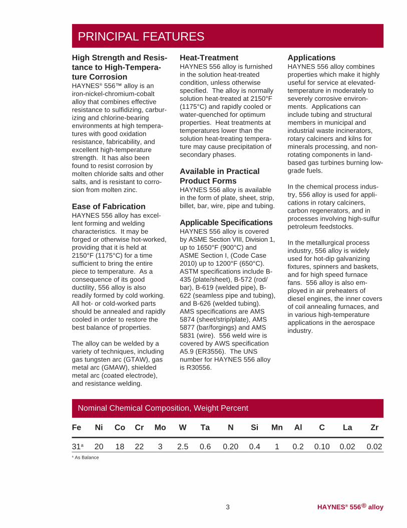
An iron-nickel-chromium-cobalt alloy that combineseffective resistance tosulfidizing, carburizing andchlorine-bearing environ-ments with good oxidationresistance, fabricability andexcellent high-temperaturestrength.
H-3013E
HIGH-TEMPERATURE ALLOYS
HAYNES® 556™ alloy

HAYNES® 556TM alloy 2 ©2005, Haynes International, Inc.
HAYNES® 556TM alloy3
PRINCIPAL FEATURESHeat-TreatmentHAYNES 556 alloy is furnishedin the solution heat-treatedcondition, unless otherwisespecified. The alloy is normallysolution heat-treated at 2150°F(1175°C) and rapidly cooled orwater-quenched for optimumproperties. Heat treatments attemperatures lower than thesolution heat-treating tempera-ture may cause precipitation ofsecondary phases.
Available in PracticalProduct FormsHAYNES 556 alloy is availablein the form of plate, sheet, strip,billet, bar, wire, pipe and tubing.
Applicable SpecificationsHAYNES 556 alloy is coveredby ASME Section VIII, Division 1,up to 1650°F (900°C) andASME Section I, (Code Case2010) up to 1200°F (650°C).ASTM specifications include B-435 (plate/sheet), B-572 (rod/bar), B-619 (welded pipe), B-622 (seamless pipe and tubing),and B-626 (welded tubing).AMS specifications are AMS5874 (sheet/strip/plate), AMS5877 (bar/forgings) and AMS5831 (wire). 556 weld wire iscovered by AWS specificationA5.9 (ER3556). The UNSnumber for HAYNES 556 alloyis R30556.
ApplicationsHAYNES 556 alloy combinesproperties which make it highlyuseful for service at elevated-temperature in moderately toseverely corrosive environ-ments. Applications caninclude tubing and structuralmembers in municipal andindustrial waste incinerators,rotary calciners and kilns forminerals processing, and non-rotating components in land-based gas turbines burning low-grade fuels.
In the chemical process indus-try, 556 alloy is used for appli-cations in rotary calciners,carbon regenerators, and inprocesses involving high-sulfurpetroleum feedstocks.
In the metallurgical processindustry, 556 alloy is widelyused for hot-dip galvanizingfixtures, spinners and baskets,and for high speed furnacefans. 556 alloy is also em-ployed in air preheaters ofdiesel engines, the inner coversof coil annealing furnaces, andin various high-temperatureapplications in the aerospaceindustry.
High Strength and Resis-tance to High-Tempera-ture CorrosionHAYNES® 556™ alloy is aniron-nickel-chromium-cobaltalloy that combines effectiveresistance to sulfidizing, carbur-izing and chlorine-bearingenvironments at high tempera-tures with good oxidationresistance, fabricability, andexcellent high-temperaturestrength. It has also beenfound to resist corrosion bymolten chloride salts and othersalts, and is resistant to corro-sion from molten zinc.
Ease of FabricationHAYNES 556 alloy has excel-lent forming and weldingcharacteristics. It may beforged or otherwise hot-worked,providing that it is held at2150°F (1175°C) for a timesufficient to bring the entirepiece to temperature. As aconsequence of its goodductility, 556 alloy is alsoreadily formed by cold working.All hot- or cold-worked partsshould be annealed and rapidlycooled in order to restore thebest balance of properties.
The alloy can be welded by avariety of techniques, includinggas tungsten arc (GTAW), gasmetal arc (GMAW), shieldedmetal arc (coated electrode),and resistance welding.
Nominal Chemical Composition, Weight Percent
Fe Ni Co Cr Mo W Ta N Si Mn Al C La Zr
31a 20 18 22 3 2.5 0.6 0.20 0.4 1 0.2 0.10 0.02 0.02a As Balance
HAYNES® 556TM alloy 4
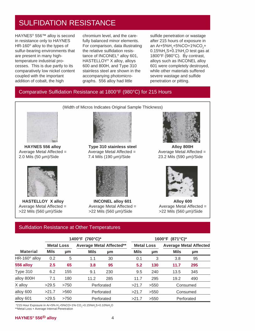
HAYNES® 556™ alloy is secondin resistance only to HAYNESHR-160® alloy to the types ofsulfur-bearing environments thatare present in many high-temperature industrial pro-cesses. This is due partly to itscomparatively low nickel contentcoupled with the importantaddition of cobalt, the high
chromium level, and the care-fully balanced minor elements.For comparison, data illustratingthe relative sulfidation resis-tance of INCONEL® alloy 601,HASTELLOY® X alloy, alloys600 and 800H, and Type 310stainless steel are shown in theaccompanying photomicro-graphs. 556 alloy had little
sulfide penetration or wastageafter 215 hours of exposure inan Ar+5%H2+5%CO+1%CO2+0.15%H2S+0.1%H2O test gas at1800°F (980°C). By contrast,alloys such as INCONEL alloy601 were completely destroyed,while other materials sufferedsevere wastage and sulfidepenetration or pitting.
SULFIDATION RESISTANCE
Comparative Sulfidation Resistance at 1800°F (980°C) for 215 Hours
46983 47006
47031 47172
(Width of Micros Indicates Original Sample Thickness)
Type 310 stainless steelAverage Metal Affected =7.4 Mils (190 µm)/Side
HAYNES 556 alloyAverage Metal Affected =2.0 Mils (50 µm)/Side
Alloy 800HAverage Metal Affected =23.2 Mils (590 µm)/Side
47021
HASTELLOY X alloyAverage Metal Affected =>22 Mils (560 µm)/Side
INCONEL alloy 601Average Metal Affected =>22 Mils (560 µm)/Side
Alloy 600Average Metal Affected =>22 Mils (560 µm)/Side
47175
Sulfidation Resistance at Other Temperatures
MaterialHR-160® alloy556 alloyType 310alloy 800HX alloyalloy 600alloy 601
1600°F (871°C)*
*215 Hour Exposure in Ar+5% H2+5%CO+1% CO2+0.15%H2S+0.10%H2O**Metal Loss + Average Internal Penetration
Average Metal AffectedMils µm3.8 95
11.7 29513.5 34519.2 490
ConsumedConsumedPerforated
Mils µm0.1 35.2 1309.5 240
11.7 295>21.7 >550>21.7 >550>21.7 >550
Mils µm0.2 52.5 656.2 1557.1 180
>29.5 >750>21.7 >560>29.5 >750
Average Metal Affected**Mils µm1.1 303.8 959.1 230
11.2 285PerforatedPerforatedPerforated
Metal Loss1400°F (760°C)*
Metal Loss
HAYNES® 556TM alloy
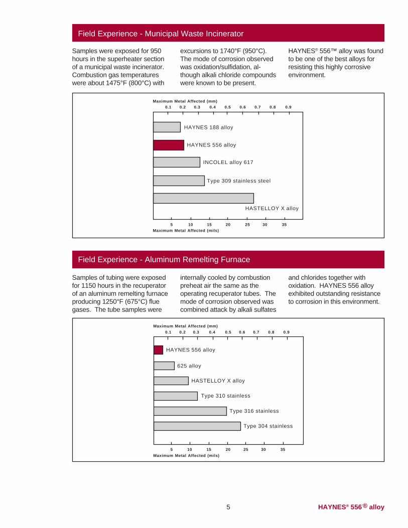
Field Experience - Municipal Waste Incinerator
Samples were exposed for 950hours in the superheater sectionof a municipal waste incinerator.Combustion gas temperatureswere about 1475°F (800°C) with
excursions to 1740°F (950°C).The mode of corrosion observedwas oxidation/sulfidation, al-though alkali chloride compoundswere known to be present.
HAYNES® 556™ alloy was foundto be one of the best alloys forresisting this highly corrosiveenvironment.
Field Experience - Aluminum Remelting Furnace
internally cooled by combustionpreheat air the same as theoperating recuperator tubes. Themode of corrosion observed wascombined attack by alkali sulfates
and chlorides together withoxidation. HAYNES 556 alloyexhibited outstanding resistanceto corrosion in this environment.
Samples of tubing were exposedfor 1150 hours in the recuperatorof an aluminum remelting furnaceproducing 1250°F (675°C) fluegases. The tube samples were
5
HAYNES 188 alloy
HAYNES 556 alloy
HASTELLOY X alloy
INCOLEL alloy 617
Type 309 stainless steel
0.1 0.2 0.3 0.4 0.5 0.6 0.7 0.8 0.9Maximum Metal Affected (mm)
5Maximum Metal Affected (mils)
10 15 20 25 30 35
625 alloy
HAYNES 556 alloy
HASTELLOY X alloy
Type 304 stainless
0.1 0.2 0.3 0.4 0.5 0.6 0.7 0.8 0.9Maximum Metal Affected (mm)
5Maximum Metal Affected (mils)
10 15 20 25 30 35
Type 316 stainless
Type 310 stainless
HAYNES® 556TM alloy 6
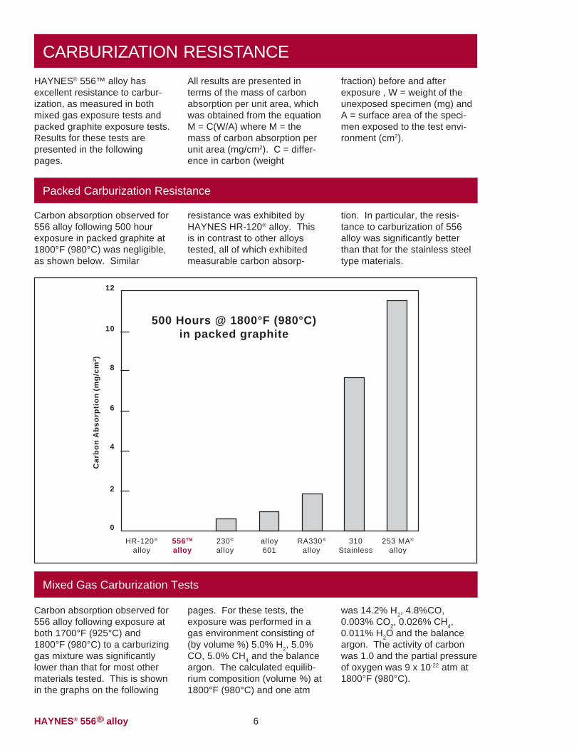
CARBURIZATION RESISTANCE
Packed Carburization Resistance
HAYNES® 556™ alloy hasexcellent resistance to carbur-ization, as measured in bothmixed gas exposure tests andpacked graphite exposure tests.Results for these tests arepresented in the followingpages.
All results are presented interms of the mass of carbonabsorption per unit area, whichwas obtained from the equationM = C(W/A) where M = themass of carbon absorption perunit area (mg/cm2). C = differ-ence in carbon (weight
fraction) before and afterexposure , W = weight of theunexposed specimen (mg) andA = surface area of the speci-men exposed to the test envi-ronment (cm2).
Carbon absorption observed for556 alloy following 500 hourexposure in packed graphite at1800°F (980°C) was negligible,as shown below. Similar
resistance was exhibited byHAYNES HR-120® alloy. Thisis in contrast to other alloystested, all of which exhibitedmeasurable carbon absorp-
tion. In particular, the resis-tance to carburization of 556alloy was significantly betterthan that for the stainless steeltype materials.
Mixed Gas Carburization Tests
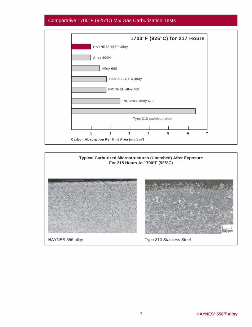
pages. For these tests, theexposure was performed in agas environment consisting of(by volume %) 5.0% H2, 5.0%CO, 5.0% CH4 and the balanceargon. The calculated equilib-rium composition (volume %) at1800°F (980°C) and one atm
was 14.2% H2, 4.8%CO,0.003% CO2, 0.026% CH4,0.011% H2O and the balanceargon. The activity of carbonwas 1.0 and the partial pressureof oxygen was 9 x 10-22 atm at1800°F (980°C).
Carbon absorption observed for556 alloy following exposure atboth 1700°F (925°C) and1800°F (980°C) to a carburizinggas mixture was significantlylower than that for most othermaterials tested. This is shownin the graphs on the following
253 MA®
alloy
Car
bon
Abs
orpt
ion
(mg/
cm2 )
10
310Stainless
RA330®
alloyalloy601
230®
alloyHR-120®
alloy556TM
alloy
12
8
6
4
2
0
500 Hours @ 1800°F (980°C)in packed graphite
HAYNES® 556TM alloy7
Comparative 1700°F (925°C) Mix Gas Carburization Tests
Typical Carburized Microstructures (Unetched) After ExposureFor 215 Hours At 1700°F (925°C)
HAYNES 556 alloy Type 310 Stainless Steel
4470844861
Alloy 800H
HAYNES® 556TM alloy
HASTELLOY X alloy
INCONEL alloy 617
1700°F (925°C) for 217 Hours
1
Carbon Absorption Per Unit Area (mg/cm2)
Alloy 600
Type 310 stainless steel
INCONEL alloy 601
2 3 4 5 6 7
HAYNES® 556TM alloy 8
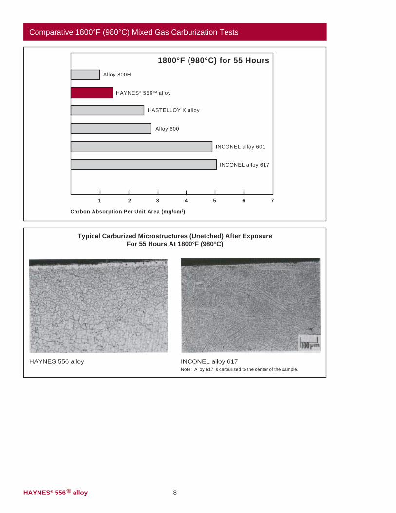
Comparative 1800°F (980°C) Mixed Gas Carburization Tests
Typical Carburized Microstructures (Unetched) After ExposureFor 55 Hours At 1800°F (980°C)
4487644714
HAYNES 556 alloy INCONEL alloy 617Note: Alloy 617 is carburized to the center of the sample.
Alloy 800H
HAYNES® 556TM alloy
HASTELLOY X alloy
INCONEL alloy 617
1800°F (980°C) for 55 Hours
1
Carbon Absorption Per Unit Area (mg/cm2)
Alloy 600
INCONEL alloy 601
2 3 4 5 6 7
HAYNES® 556TM alloy9
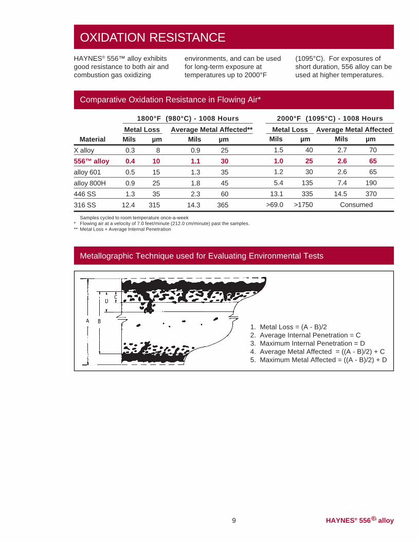
OXIDATION RESISTANCEHAYNES® 556™ alloy exhibitsgood resistance to both air andcombustion gas oxidizing
environments, and can be usedfor long-term exposure attemperatures up to 2000°F
(1095°C). For exposures ofshort duration, 556 alloy can beused at higher temperatures.
Average Metal Affected** Metal Loss Average Metal Affected
Comparative Oxidation Resistance in Flowing Air*
MaterialX alloy556™ alloyalloy 601alloy 800H446 SS316 SS
Mils µm0.3 80.4 100.5 150.9 251.3 35
12.4 315
Mils µm0.9 251.1 301.3 351.8 452.3 60
14.3 365
Metal LossMils µm
1.5 401.0 251.2 305.4 135
13.1 335>69.0 >1750
Mils µm2.7 702.6 652.6 657.4 190
14.5 370Consumed
1800°F (980°C) - 1008 Hours 2000°F (1095°C) - 1008 Hours
Samples cycled to room temperature once-a-week* Flowing air at a velocity of 7.0 feet/minute (212.0 cm/minute) past the samples.** Metal Loss + Average Internal Penetration
Metallographic Technique used for Evaluating Environmental Tests
1. Metal Loss = (A - B)/22. Average Internal Penetration = C3. Maximum Internal Penetration = D4. Average Metal Affected = ((A - B)/2) + C5. Maximum Metal Affected = ((A - B)/2) + D
HAYNES® 556TM alloy
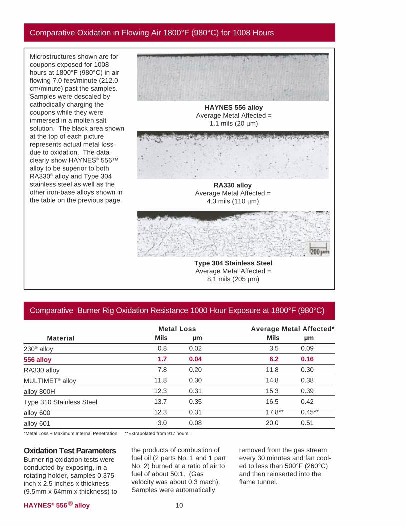
Comparative Oxidation in Flowing Air 1800°F (980°C) for 1008 Hours
45626
49258
Microstructures shown are forcoupons exposed for 1008hours at 1800°F (980°C) in airflowing 7.0 feet/minute (212.0cm/minute) past the samples.Samples were descaled bycathodically charging thecoupons while they wereimmersed in a molten saltsolution. The black area shownat the top of each picturerepresents actual metal lossdue to oxidation. The dataclearly show HAYNES® 556™alloy to be superior to bothRA330® alloy and Type 304stainless steel as well as theother iron-base alloys shown inthe table on the previous page.
HAYNES 556 alloyAverage Metal Affected =
1.1 mils (20 µm)
RA330 alloyAverage Metal Affected =
4.3 mils (110 µm)
Type 304 Stainless SteelAverage Metal Affected =
8.1 mils (205 µm)
Oxidation Test ParametersBurner rig oxidation tests wereconducted by exposing, in arotating holder, samples 0.375inch x 2.5 inches x thickness(9.5mm x 64mm x thickness) to
the products of combustion offuel oil (2 parts No. 1 and 1 partNo. 2) burned at a ratio of air tofuel of about 50:1. (Gasvelocity was about 0.3 mach).Samples were automatically
removed from the gas streamevery 30 minutes and fan cool-ed to less than 500°F (260°C)and then reinserted into theflame tunnel.
Comparative Burner Rig Oxidation Resistance 1000 Hour Exposure at 1800°F (980°C)
Material230® alloy556 alloyRA330 alloyMULTIMET® alloyalloy 800HType 310 Stainless Steelalloy 600alloy 601*Metal Loss + Maximum Internal Penetration **Extrapolated from 917 hours
Mils µm3.5 0.096.2 0.16
11.8 0.3014.8 0.3815.3 0.3916.5 0.4217.8** 0.45**20.0 0.51
Average Metal Affected*Metal LossMils µm0.8 0.021.7 0.047.8 0.20
11.8 0.3012.3 0.3113.7 0.3512.3 0.313.0 0.08
10
HAYNES® 556TM alloy11
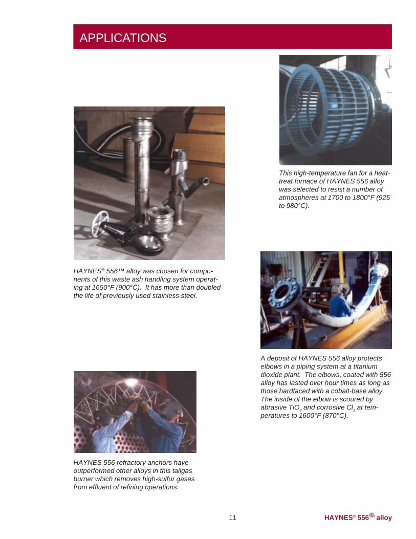
APPLICATIONS
HAYNES® 556™ alloy was chosen for compo-nents of this waste ash handling system operat-ing at 1650°F (900°C). It has more than doubledthe life of previously used stainless steel.
A deposit of HAYNES 556 alloy protectselbows in a piping system at a titaniumdioxide plant. The elbows, coated with 556alloy has lasted over hour times as long asthose hardfaced with a cobalt-base alloy.The inside of the elbow is scoured byabrasive TiO2 and corrosive Cl2 at tem-peratures to 1600°F (870°C).
HAYNES 556 refractory anchors haveoutperformed other alloys in this tailgasburner which removes high-sulfur gasesfrom effluent of refining operations.
This high-temperature fan for a heat-treat furnace of HAYNES 556 alloywas selected to resist a number ofatmospheres at 1700 to 1800°F (925to 980°C).
HAYNES® 556TM alloy 12
RESISTANCE TO CHLORINE-BEARING ENVIRONMENTS
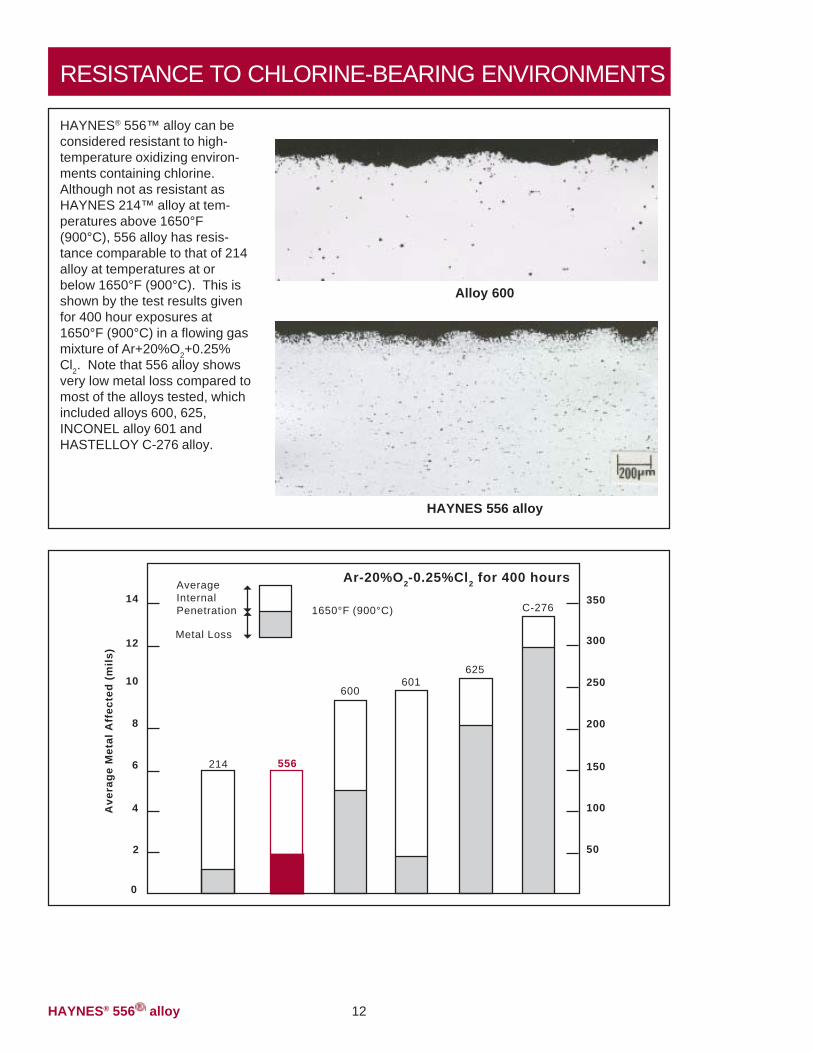
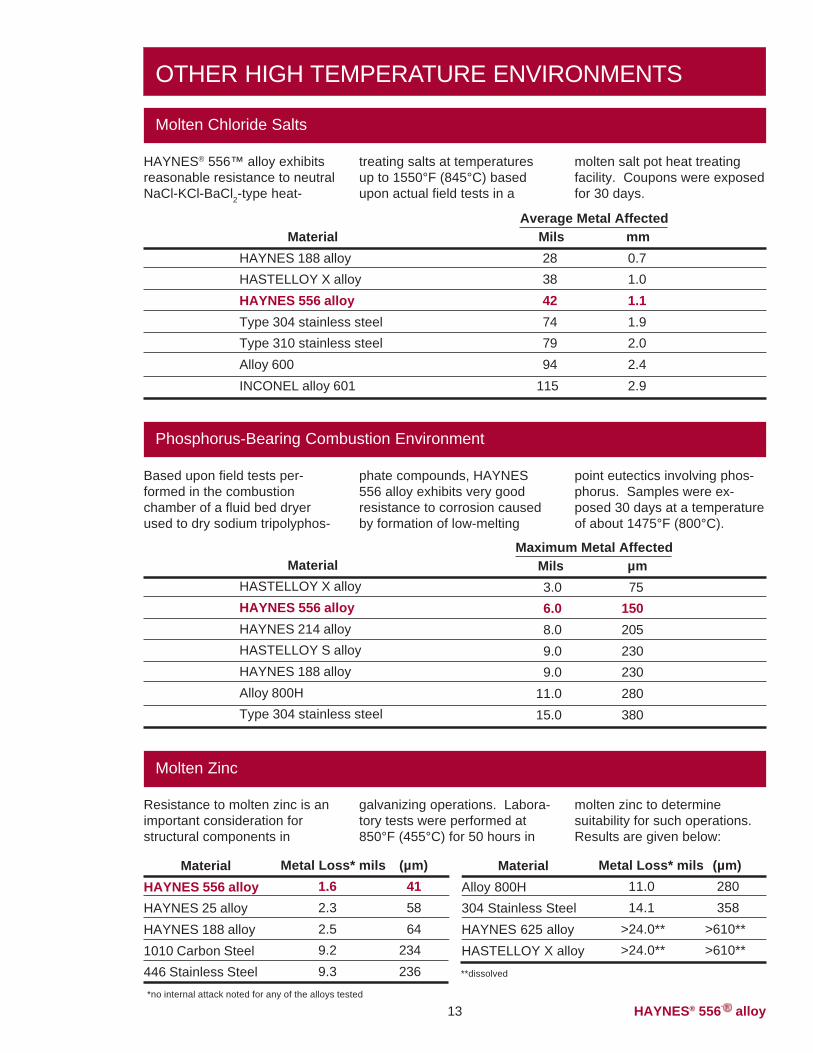
HAYNES® 556™ alloy can beconsidered resistant to high-temperature oxidizing environ-ments containing chlorine.Although not as resistant asHAYNES 214™ alloy at tem-peratures above 1650°F(900°C), 556 alloy has resis-tance comparable to that of 214alloy at temperatures at orbelow 1650°F (900°C). This isshown by the test results givenfor 400 hour exposures at1650°F (900°C) in a flowing gasmixture of Ar+20%O2+0.25%Cl2. Note that 556 alloy showsvery low metal loss compared tomost of the alloys tested, whichincluded alloys 600, 625,INCONEL alloy 601 andHASTELLOY C-276 alloy.
47535
47263
Alloy 600
HAYNES 556 alloy
C-276
Ave
rage
Met
al A
ffec
ted
(mils
)
14
625601
600
214 556
12
10
8
6
4
2
0
50
100
150
200
250
300
3501650°F (900°C)
Metal Loss
AverageInternalPenetration
Ar-20%O2-0.25%Cl2 for 400 hours
HAYNES® 556TM alloy13
Maximum Metal Affected
OTHER HIGH TEMPERATURE ENVIRONMENTS
Molten Chloride Salts
HAYNES® 556™ alloy exhibitsreasonable resistance to neutralNaCl-KCl-BaCl2-type heat-
treating salts at temperaturesup to 1550°F (845°C) basedupon actual field tests in a
molten salt pot heat treatingfacility. Coupons were exposedfor 30 days.
MaterialHAYNES 188 alloyHASTELLOY X alloyHAYNES 556 alloyType 304 stainless steelType 310 stainless steelAlloy 600INCONEL alloy 601
Mils mm28 0.738 1.042 1.174 1.979 2.094 2.4
115 2.9
Average Metal Affected
Phosphorus-Bearing Combustion Environment
Based upon field tests per-formed in the combustionchamber of a fluid bed dryerused to dry sodium tripolyphos-
phate compounds, HAYNES556 alloy exhibits very goodresistance to corrosion causedby formation of low-melting
point eutectics involving phos-phorus. Samples were ex-posed 30 days at a temperatureof about 1475°F (800°C).
Mils µm3.0 756.0 1508.0 2059.0 2309.0 230
11.0 28015.0 380
MaterialHASTELLOY X alloyHAYNES 556 alloyHAYNES 214 alloyHASTELLOY S alloyHAYNES 188 alloyAlloy 800HType 304 stainless steel
Molten Zinc
Resistance to molten zinc is animportant consideration forstructural components in
molten zinc to determinesuitability for such operations.Results are given below:
galvanizing operations. Labora-tory tests were performed at850°F (455°C) for 50 hours in
MaterialHAYNES 556 alloyHAYNES 25 alloyHAYNES 188 alloy1010 Carbon Steel446 Stainless Steel
Metal Loss* mils (µm)1.6 412.3 582.5 649.2 2349.3 236
Metal Loss* mils (µm)11.0 28014.1 358
>24.0** >610**>24.0** >610**
MaterialAlloy 800H304 Stainless SteelHAYNES 625 alloyHASTELLOY X alloy**dissolved
*no internal attack noted for any of the alloys tested
HAYNES® 556TM alloy 14
TYPICAL PHYSICAL PROPERTIESTemp., °F British Units Temp., °C Metric Units
Density Room 0.297 lb/in.3 Room 8.23 g/cm.3
Melting Temperature 2425-2580 1330-1415
Electrical Resistivity Room 37.5 microhm-in. Room 95.2 microhm-cm200 38.7 microhm-in. 100 98.6 microhm-cm400 40.5 microhm-in. 200 102.6 microhm-cm600 42.1 microhm-in. 300 106.5 microhm-cm800 43.5 microhm-in. 400 109.5 microhm-cm
1000 44.7 microhm-in. 500 112.5 microhm-cm1200 45.7 microhm-in. 600 115.1 microhm-cm1400 46.6 microhm-in. 700 117.2 microhm-cm1600 47.3 microhm-in. 800 119.0 microhm-cm1800 48.0 microhm-in. 900 120.7 microhm-cm2000 48.6 microhm-in. 1000 122.3 microhm-cm
1100 123.7 microhm-cmThermal Diffusivity Room 4.5 x 10⁻³ in.2/sec. Room 28.7 x 10⁻³ cm2/sec.
200 4.8 x 10⁻³ in.2/sec. 100 31.2 x 10⁻³ cm2/sec.400 5.3 x 10⁻³ in.2/sec. 200 34.2 x 10⁻³ cm2/sec.600 5.8 x 10⁻³ in.2/sec. 300 37.0 x 10⁻³ cm2/sec.800 6.3 x 10⁻³ in.2/sec. 400 39.7 x 10⁻³ cm2/sec.
1000 6.7 x 10⁻³ in.2/sec. 500 42.3 x 10⁻³ cm2/sec.1200 7.1 x 10⁻³ in.2/sec. 600 44.8 x 10⁻³ cm2/sec.1400 7.5 x 10⁻³ in.2/sec. 700 47.0 x 10⁻³ cm2/sec.1600 7.7 x 10⁻³ in.2/sec. 800 48.8 x 10⁻³ cm2/sec.1800 8.0 x 10⁻³ in.2/sec. 900 50.3 x 10⁻³ cm2/sec.2000 8.2 x 10⁻³ in.2/sec. 1000 51.6 x 10⁻³ cm2/sec.
1100 52.8 x 10⁻³ cm2/sec.Thermal Conductivity Room 77 Btu-in./ft.2 hr.-°F Room 11.1 W/m-K
200 90 Btu-in./ft.2 hr.-°F 100 13.1 W/m-K400 107 Btu-in./ft.2 hr.-°F 200 15.4 W/m-K600 122 Btu-in./ft.2 hr.-°F 300 17.3 W/m-K800 135 Btu-in./ft.2 hr.-°F 400 19.0 W/m-K
1000 148 Btu-in./ft.2 hr.-°F 500 20.8 W/m-K1200 160 Btu-in./ft.2 hr.-°F 600 22.4 W/m-K1400 173 Btu-in./ft.2 hr.-°F 700 24.0 W/m-K1600 185 Btu-in./ft.2 hr.-°F 800 25.5 W/m-K1800 197 Btu-in./ft.2 hr.-°F 900 27.2 W/m-K2000 210 Btu-in./ft.2 hr.-°F 1000 28.9 W/m-K
1100 30.4 W/m-K
HAYNES® 556TM alloy
Typical Physical Properties (continued)
Specific Heat Room 0.111 Btu/lb.-°F Room 464 J/Kg-K200 0.113 Btu/lb.-°F 100 475 J/Kg-K400 0.118 Btu/lb.-°F 200 493 J/Kg-K600 0.122 Btu/lb.-°F 300 508 J/Kg-K800 0.126 Btu/lb.-°F 400 523 J/Kg-K
1000 0.130 Btu/lb.-°F 500 538 J/Kg-K1200 0.133 Btu/lb.-°F 600 552 J/Kg-K1400 0.135 Btu/lb.-°F 700 561 J/Kg-K1600 0.140 Btu/lb.-°F 800 570 J/Kg-K1800 0.147 Btu/lb.-°F 900 595 J/Kg-K2000 0.152 Btu/lb.-°F 1000 618 J/Kg-K
1100 638 J/Kg-K
Temp., °F British Units Temp., °C Metric Units
Mean Coefficient of 70-200 8.1 microinches/in.-°F 25-100 14.7 10-6m/m-°CThermal Expansion 70-400 8.2 microinches/in.-°F 25-200 14.9 10-6m/m-°C
70-600 8.4 microinches/in.-°F 25-300 15.1 10-6m/m-°C70-800 8.6 microinches/in.-°F 25-400 15.4 10-6m/m-°C
70-1000 8.8 microinches/in.-°F 25-500 15.7 10-6m/m-°C70-1200 9.0 microinches/in.-°F 25-600 16.1 10-6m/m-°C70-1400 9.2 microinches/in.-°F 25-700 16.4 10-6m/m-°C70-1600 9.4 microinches/in.-°F 25-800 16.7 10-6m/m-°C70-1800 9.5 microinches/in.-°F 25-900 17.0 10-6m/m-°C70-2000 9.6 microinches/in.-°F 25-1000 17.1 10-6m/m-°C
25-1100 17.1 10-6m/m-°C
15
Room 29.7 x 10⁶ psi Room 205 GPa200 29.1 x 10⁶ psi 100 200 GPa400 28.2 x 10⁶ psi 200 195 GPa600 26.9 x 10⁶ psi 300 187 GPa800 25.6 x 10⁶ psi 400 179 GPa
1000 24.4 x 10⁶ psi 500 172 GPa1200 23.1 x 10⁶ psi 600 164 GPa1400 21.8 x 10⁶ psi 700 155 GPa1600 20.9 x 10⁶ psi 800 148 GPa1800 20.1 x 10⁶ psi 900 143 GPa
1000 138 GPa
Dynamic DynamicModulus of Modulus ofElasticity, Elasticity,
Temp., °F 106 psi Temp., °C GPa
DYNAMIC MODULUS OF ELASTICITY
HAYNES® 556TM alloy
APPLICATIONS
16492
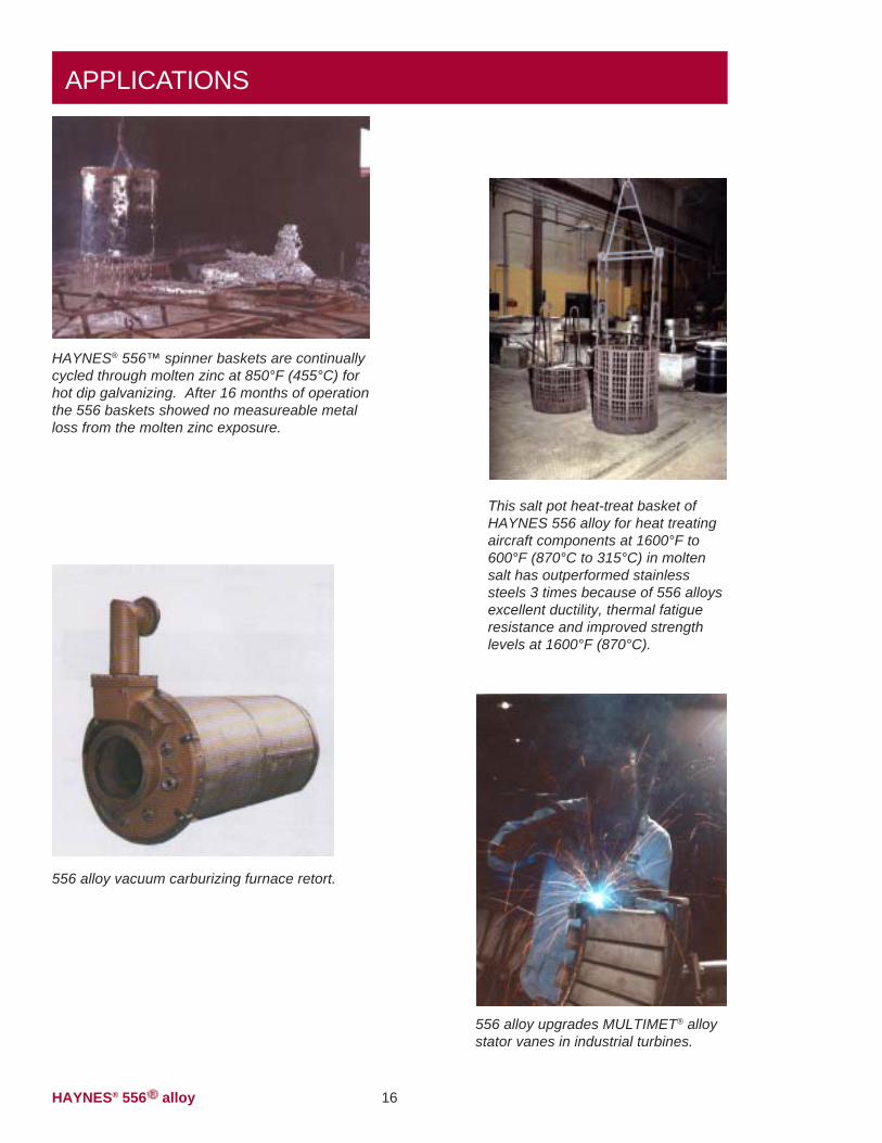
HAYNES® 556™ spinner baskets are continuallycycled through molten zinc at 850°F (455°C) forhot dip galvanizing. After 16 months of operationthe 556 baskets showed no measureable metalloss from the molten zinc exposure.
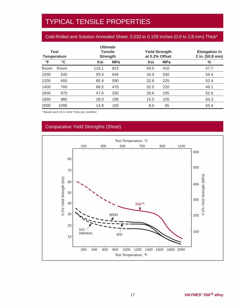
This salt pot heat-treat basket ofHAYNES 556 alloy for heat treatingaircraft components at 1600°F to600°F (870°C to 315°C) in moltensalt has outperformed stainlesssteels 3 times because of 556 alloysexcellent ductility, thermal fatigueresistance and improved strengthlevels at 1600°F (870°C).
����� 1538329403-515�-3116
1795630567-508
556 alloy vacuum carburizing furnace retort.
556 alloy upgrades MULTIMET® alloystator vanes in industrial turbines.
16
HAYNES® 556TM alloy17
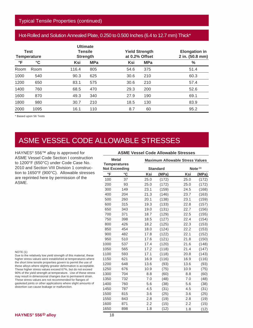
TYPICAL TENSILE PROPERTIES
Cold-Rolled and Solution Annealed Sheet, 0.033 to 0.109 Inches (0.8 to 2.8 mm) Thick*
Elongation in2 in. (50.8 mm)
%47.754.452.449.152.663.355.4
TestTemperature
°F °CRoom Room1000 5401200 6501400 7601600 8701800 9802000 1095
Yield Strengthat 0.2% Offset
Ksi MPa59.5 41034.9 24032.8 22532.0 22028.6 19515.5 105
8.0 55
UltimateTensile
StrengthKsi MPa
118.1 81593.4 64585.4 59068.5 47047.6 33028.0 19514.8 100
* Based upon 10 or more Tests per condition
Comparative Yield Strengths (Sheet)
100
200
300
400
600
500
1100900700500300100
80
70
60
50
40
30
20
10
310stainless
200 400 600 800 1000 1200 1400 1600 1800 2000
600
800H
556™
0.2%
Yie
ld S
tren
gth
(Ksi
)
0.2%
Yie
ld S
tren
gth
(MP
a)
Test Temperature, °F
Test Temperature, °C
HAYNES® 556TM alloy
Typical Tensile Properties (continued)
Hot-Rolled and Solution Annealed Plate, 0.250 to 0.500 Inches (6.4 to 12.7 mm) Thick*
Elongation in2 in. (50.8 mm)
%51.460.357.452.669.183.995.2
TestTemperature
°F °CRoom Room1000 5401200 6501400 7601600 8701800 9802000 1095
Yield Strengthat 0.2% Offset
Ksi MPa54.6 37530.6 21030.6 21029.3 20027.9 19018.5 130
8.7 60
UltimateTensile
StrengthKsi MPa
116.4 80590.3 62583.1 57568.5 47049.3 34030.7 21016.1 110
* Based upon 56 Tests
18
ASME VESSEL CODE ALLOWABLE STRESSES
Note (1)
Ksi (MPa)25.0 (172)25.0 (172)24.5 (168)23.7 (163)23.1 (159)22.8 (157)22.7 (156)22.5 (155)22.4 (154)22.3 (153)22.2 (153)22.1 (152)21.8 (150)21.6 (148)21.4 (147)20.8 (143)16.9 (116)13.6 (93)10.9 (75)
8.8 (60)7.0 (48)5.6 (38)4.5 (31)3.6 (25)2.8 (19)2.2 (15)1.8 (12)
StandardKsi (MPa)
25.0 (172)25.0 (172)23.1 (159)21.3 (146)20.1 (138)19.3 (133)19.0 (131)18.7 (129)18.5 (127)18.2 (125)18.0 (124)17.8 (122)17.6 (121)17.4 (120)17.2 (118)17.1 (118)16.9 (116)13.6 (93)10.9 (75)
8.8 (60)7.0 (48)5.6 (38)4.5 (31)3.6 (25)2.8 (19)2.2 (15)1.8 (12)
°F °C100 37200 93300 149400 204500 260600 315650 343700 371750 398800 426850 454900 482950 510
1000 5371050 5651100 5931150 6211200 6481250 6761300 7041350 7321400 7601450 7871500 8151550 8431600 8711650 898
NOTE (1)Due to the relatively low yield strength of this material, thesehigher stress values were established at temperatures wherethe short time tensile properties govern to permit the use ofthese alloys where slightly greater deformation is acceptable.These higher stress values exceed 67%, but do not exceed90% of the yield strength at temperature. Use of these stressmay result in dimensional changes due to permanent strain.These stress values are not recommended for flanges ofgasketed joints or other applications where slight amounts ofdistortion can cause leakage or malfunction.
ASME Vessel Code Allowable Stresses
Maximum Allowable Stress ValuesMetalTemperaturesNot Exceeding
HAYNES® 556™ alloy is approved forASME Vessel Code Section I constructionto 1200°F (650°C) under Code Case No.2010 and Section VIII Division 1 construc-tion to 1650°F (900°C). Allowable stressesare reprinted here by permission of theASME.
HAYNES® 556TM alloy19
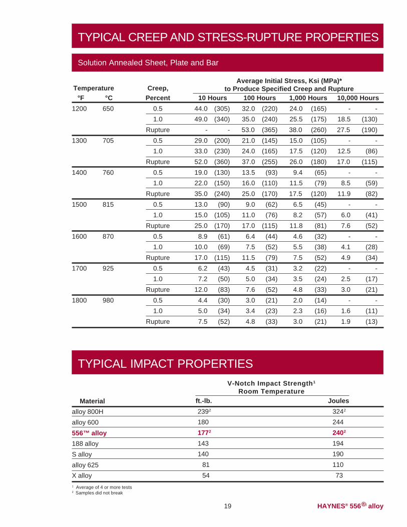
TYPICAL CREEP AND STRESS-RUPTURE PROPERTIES
Temperature°F °C
1200 650
1300 705
1400 760
1500 815
1600 870
1700 925
1800 980
Creep,Percent
0.51.0
Rupture0.51.0
Rupture0.51.0
Rupture0.51.0
Rupture0.51.0
Rupture0.51.0
Rupture0.51.0
Rupture
10 Hours44.0 (305)49.0 (340)
- -29.0 (200)33.0 (230)52.0 (360)19.0 (130)22.0 (150)35.0 (240)13.0 (90)15.0 (105)25.0 (170)8.9 (61)
10.0 (69)17.0 (115)6.2 (43)7.2 (50)
12.0 (83)4.4 (30)5.0 (34)7.5 (52)
100 Hours32.0 (220)35.0 (240)53.0 (365)21.0 (145)24.0 (165)37.0 (255)13.5 (93)16.0 (110)25.0 (170)
9.0 (62)11.0 (76)17.0 (115)
6.4 (44)7.5 (52)
11.5 (79)4.5 (31)5.0 (34)7.6 (52)3.0 (21)3.4 (23)4.8 (33)
1,000 Hours24.0 (165)25.5 (175)38.0 (260)15.0 (105)17.5 (120)26.0 (180)9.4 (65)
11.5 (79)17.5 (120)
6.5 (45)8.2 (57)
11.8 (81)4.6 (32)5.5 (38)7.5 (52)3.2 (22)3.5 (24)4.8 (33)2.0 (14)2.3 (16)3.0 (21)
10,000 Hours- -
18.5 (130)27.5 (190)
- -12.5 (86)17.0 (115)
- -8.5 (59)
11.9 (82)- -
6.0 (41)7.6 (52)
- -4.1 (28)4.9 (34)
- -2.5 (17)3.0 (21)
- -1.6 (11)1.9 (13)
Average Initial Stress, Ksi (MPa)*to Produce Specified Creep and Rupture
Solution Annealed Sheet, Plate and Bar
TYPICAL IMPACT PROPERTIESV-Notch Impact Strength1
Room TemperatureMaterial
alloy 800Halloy 600556™ alloy188 alloyS alloyalloy 625X alloy
ft.-lb. Joules2392 3242
180 2441772 2402
143 194140 190
81 11054 73
1 Average of 4 or more tests2 Samples did not break
HAYNES® 556TM alloy 20
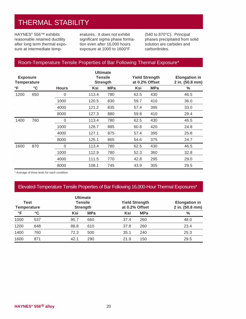
THERMAL STABILITYeratures. It does not exhibitsignificant sigma phase forma-tion even after 16,000 hoursexposure at 1000 to 1600°F
(540 to 870°C). Principalphases precipitated from solidsolution are carbides andcarbonitrides.
Room-Temperature Tensile Properties of Bar Following Thermal Exposure*
Elongation in2 in. (50.8 mm)
%46.536.033.029.446.524.825.824.746.532.829.029.5
UltimateTensile
StrengthKsi MPa
113.4 780120.5 830121.2 835127.3 880113.4 780128.7 885127.1 875125.1 865113.4 780112.9 780111.5 770108.1 745
ExposureTemperature°F °C1200 650
1400 760
1600 870
Hours0
100040008000
0100040008000
0100040008000
* Average of three tests for each condition
Yield Strengthat 0.2% Offset
Ksi MPa62.5 43059.7 41057.4 39559.8 41062.5 43060.8 42057.4 39554.6 37562.5 43052.3 36042.8 29543.9 305
HAYNES® 556™ exhibitsreasonable retained ductilityafter long term thermal expo-sure at intermediate temp-
Elevated-Temperature Tensile Properties of Bar Following 16,000-Hour Thermal Exposures*
Elongation in2 in. (50.8 mm)
%48.023.425.329.5
TestTemperature
°F °C1000 5371200 6481400 7601600 871
UltimateTensile
StrengthKsi MPa
95.7 66088.8 61072.3 50042.1 290
Yield Strengthat 0.2% Offset
Ksi MPa37.4 26037.8 26035.1 24021.9 150
HAYNES® 556TM alloy21
Thermal Stability (continued)
Room-Temperature Tensile Properties of Sheet Following1000-Hour Thermal Exposures*
Elongation in2 in. (50.8 mm)
%47.737.917.020.4
TestTemperature
°F °CRoom Room1200 6481400 7601600 871
Yield Strengthat 0.2% Offset
Ksi MPa59.5 41053.4 37053.8 37046.6 320
UltimateTensile
StrengthKsi MPa
118.1 815118.4 815118.8 820111.0 765
* Average of two or more tests
FABRICATION CHARACTERISTICS
Heat Treatment
2125°F (1165°C), but resultingmaterial properties will bealtered accordingly. Annealingduring fabrication can beperformed at even lowertemperatures, but a final,subsequent solution heat
treatment is needed to produceoptimum properties and struc-ture. Please refer to followingsections and publication H-3159for additional information.
HAYNES® 556™ alloy isnormally final solution heat-treated at 2150°F (1175°C) fora time commensurate withsection thickness. Solutionheat-treating can be performedat temperatures as low as about
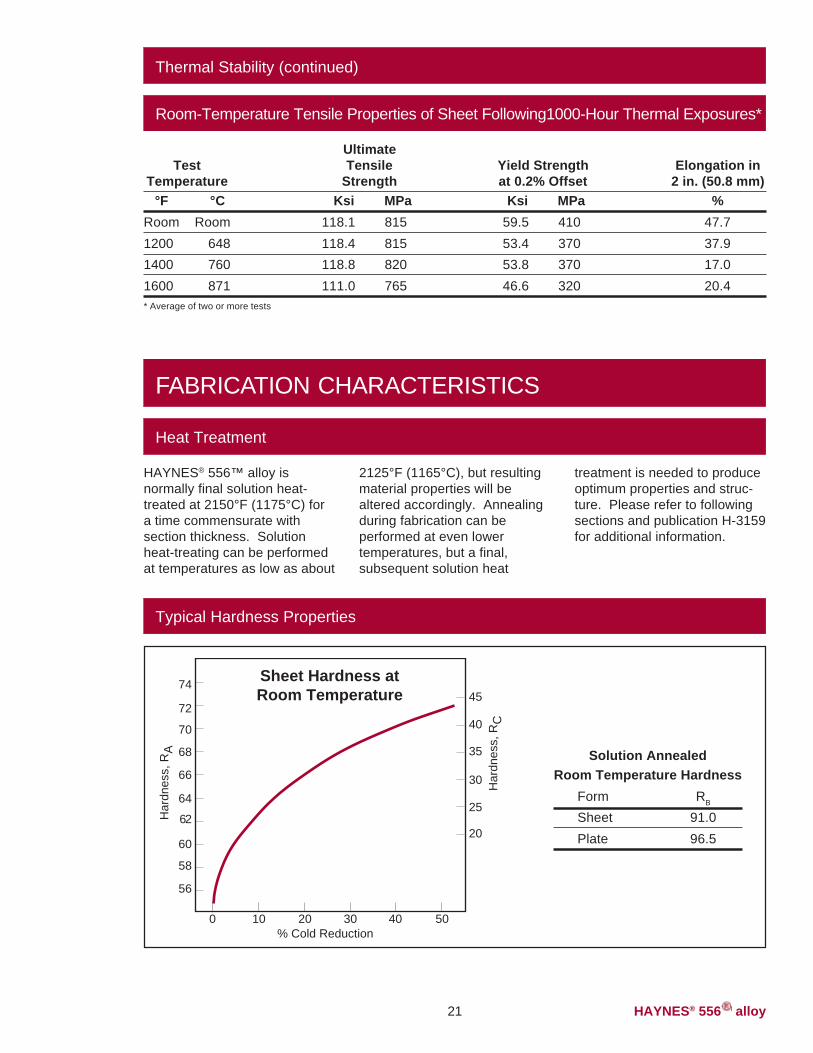
Typical Hardness Properties
20
25
30
35
40
45
Har
dnes
s, R
C
Har
dnes
s, R
A
74
72
70
68
66
64
62
60
58
56
0 10 20 30 40 50% Cold Reduction
Solution AnnealedRoom Temperature Hardness
Form RB
Sheet 91.0Plate 96.5
Sheet Hardness atRoom Temperature
HAYNES® 556TM alloy 22
Fabrication Characteristics (continued)
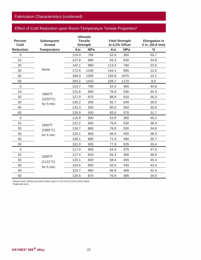
Effect of Cold Reduction upon Room-Temperature Tensile Properties*
Elongation in2 in. (50.8 mm)
%50.734.823.512.010.18.0
44.834.330.326.630.631.745.236.934.838.336.733.447.048.045.443.042.435.0
PercentCold
Reduction0
1020304050
01020304050
01020304050
01020304050
Yield Strengthat 0.2% Offset
Ksi MPa52.9 36593.3 645
113.3 780144.1 995155.8 1075169.7 117052.6 36576.9 53088.8 61092.7 64080.0 55083.0 57052.9 36576.8 53076.8 53066.0 45571.4 49077.9 53554.3 37555.3 38058.4 40563.5 44066.9 46070.8 485
UltimateTensile
StrengthKsi MPa
115.0 795127.8 880142.1 980172.6 1190189.3 1305204.2 1410114.7 790121.6 840127.0 875135.2 930133.3 920135.0 930115.8 800122.2 845124.7 860125.1 865128.1 885131.0 905117.0 805117.4 810120.1 830123.6 850124.7 860126.6 875
SubsequentAnneal
Temperature
None
1850°F(1010°C)for 5 min.
* Based upon rolling reductions taken upon 0.120-inch (3.0mm) thick sheet. Duplicate tests
2050°F(1121°C)for 5 min.
1950°F(1065°C)for 5 min.
HAYNES® 556TM alloy23
Fabrication Characteristics (continued)
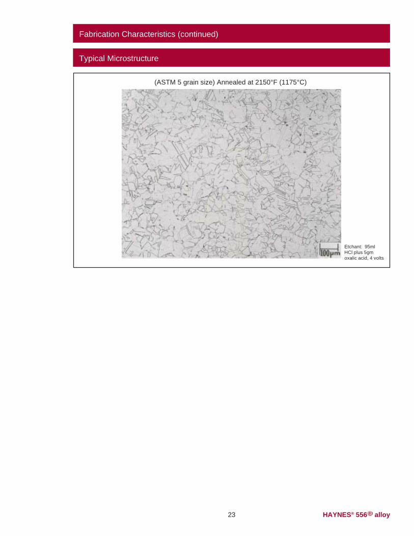
Typical Microstructure
(ASTM 5 grain size) Annealed at 2150°F (1175°C)
50244
Etchant: 95mlHCl plus 5gmoxalic acid, 4 volts
HAYNES® 556TM alloy 24
HAYNES® 556™ alloy is readilywelded by gas tungsten arc(GTAW), gas metal arc(GMAW), shielded metal arc(coated electrode), and resis-tance welding techniques.Submerged arc welding is notrecommended as this processis characterized by high heatinput to the base metal andslow cooling of the weld. Thesefactors can increase weldrestraint and promote cracking.
Base Metal PreparationThe joint surface and adjacentarea should be thoroughlycleaned before welding. Allgrease, oil, crayon marks, sulfurcompounds and other foreignmatter should be removed. It ispreferable, but not necessary,that the alloy be in the solution-annealed condition whenwelded.
WELDINGFiller Metal SelectionMatching composition fillermetal is recommended forjoining 556 alloy. For shieldedmetal-arc welding, MULTIMETelectrodes (AMS 5795) aresuggested. For dissimilar metaljoining of 556 alloy to nickel- orcobalt-base materials, 556 fillermetal will generally be a goodselection, but HASTELLOY Salloy (AMS 5838A) orHASTELLOY W alloy (AMS5786B, 5787A) welding prod-ucts may be used. For dissimi-lar welding to iron-base materi-als, 556 filler metal is recom-mended. Please see publica-tion H-3159.
Preheating, InterpassTemperatures and Post-Weld Heat TreatmentPreheat is not usually requiredso long as base metal to bewelded is above 32°F (0°C).Interpass temperatures gener-ally should be low. Auxiliarycooling methods may be usedbetween weld passes, asneeded, providing that suchmethods do not introducecontaminants. Post-weld heattreatment is not normallyrequired for 556 alloys.
Nominal WeldingParametersNominal welding parametersare provided as a guide forperforming typical operations.These are based upon weldingconditions used in HaynesInternational, Inc. laboratories.For further information, pleaseconsult Haynes publicationH-3159.
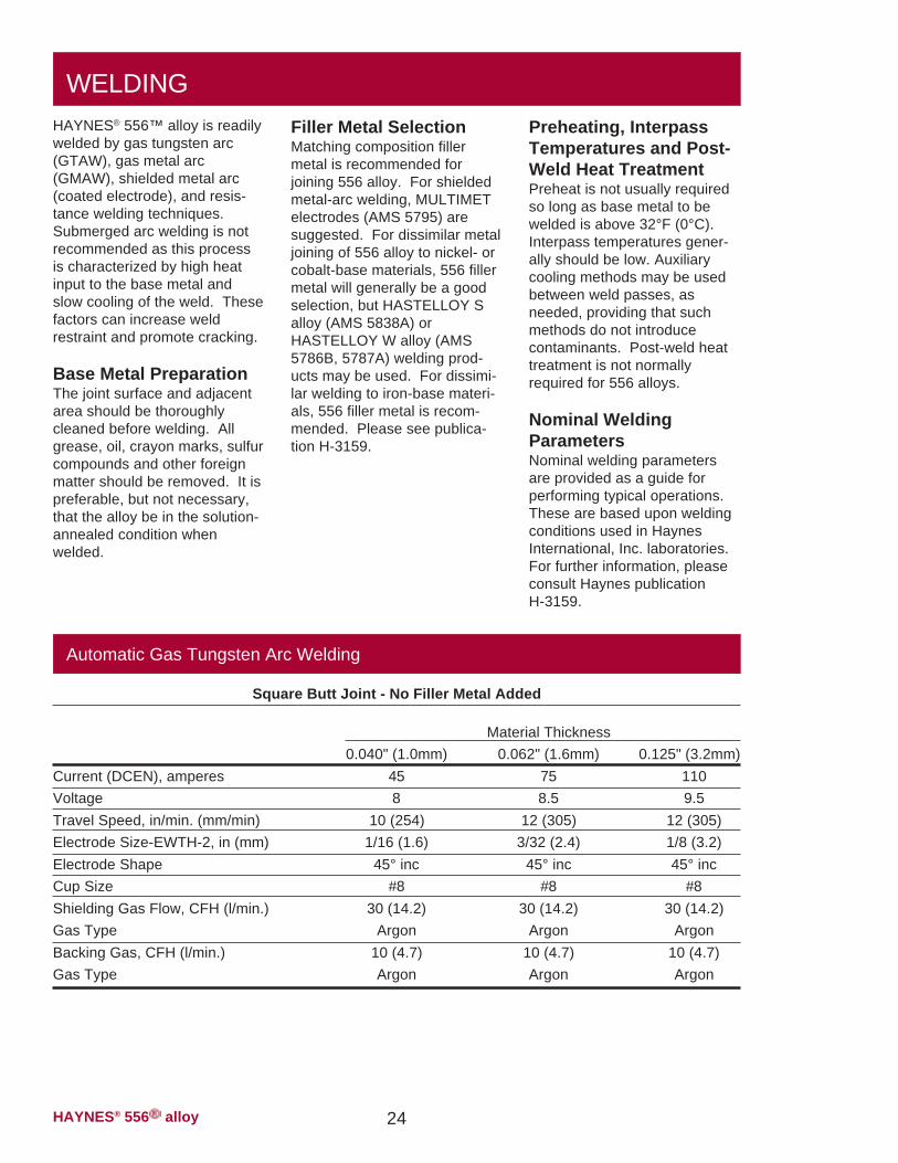
Automatic Gas Tungsten Arc Welding
Square Butt Joint - No Filler Metal Added
Material Thickness0.040" (1.0mm) 0.062" (1.6mm) 0.125" (3.2mm)
Current (DCEN), amperes 45 75 110Voltage 8 8.5 9.5Travel Speed, in/min. (mm/min) 10 (254) 12 (305) 12 (305)Electrode Size-EWTH-2, in (mm) 1/16 (1.6) 3/32 (2.4) 1/8 (3.2)Electrode Shape 45° inc 45° inc 45° incCup Size #8 #8 #8Shielding Gas Flow, CFH (l/min.) 30 (14.2) 30 (14.2) 30 (14.2)Gas Type Argon Argon ArgonBacking Gas, CFH (l/min.) 10 (4.7) 10 (4.7) 10 (4.7)Gas Type Argon Argon Argon
HAYNES® 556TM alloy25
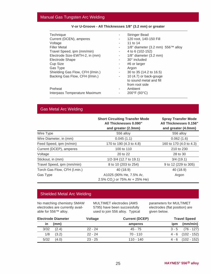
Manual Gas Tungsten Arc Welding
V-or U-Groove - All Thicknesses 1/8" (3.2 mm) or greater
Technique - Stringer BeadCurrent (DCEN), amperes - 120 root, 140-150 FillVoltage - 11 to 14Filler Metal - 1/8" diameter (3.2 mm) 556™ alloyTravel Speed, ipm (mm/min) - 4 to 6 (102-152)Electrode Size-EWTH-2, in (mm) - 1/8" diameter (3.2 mm)Electrode Shape - 30° includedCup Size - #6 or largerGas Type - ArgonShielding Gas Flow, CFH (l/min.) - 30 to 35 (14.2 to 16.5)Backing Gas Flow, CFH (l/min.) - 10 (4.7) or back-gouge
to sound metal and fillfrom root side
Preheat - AmbientInterpass Temperature Maximum - 200°F (93°C)
Gas Metal Arc Welding
Short Circuiting Transfer Mode Spray Transfer ModeAll Thicknesses 0.090" All Thicknesses 0.156"
and greater (2.3mm) and greater (4.0mm)Wire Type 556 alloy 556 alloyWire Diameter, in (mm) 0.045 (1.1) 0.062 (1.6)Feed Speed, ipm (m/min) 170 to 190 (4.3 to 4.8) 160 to 170 (4.0 to 4.3)Current (DCEP), amperes 100 to 110 210 to 230Voltage 20 to 22 28 to 30Stickout, in (mm) 1/2-3/4 (12.7 to 19.1) 3/4 (19.1)Travel Speed, ipm (mm/min) 8 to 10 (203 to 254) 9 to 12 (229 to 305)Torch Gas Flow, CFH (l.min.) 40 (18.9) 40 (18.9)Gas Type A1025 (90% He, 7.5% Ar, Argon
2.5% CO2) or 75% Ar + 25% He)
Shielded Metal Arc Welding
No matching chemistry SMAWelectrodes are currently avail-able for 556™ alloy.
parameters for MULTIMETelectrodes (flat position) aregiven below.
MULTIMET electrodes (AMS5795) have been successfullyused to join 556 alloy. Typical
Electrode Diameter Voltage Current (DCEP) Travel Speedin (mm) amperes ipm (mm/min)
3/32 (2.4) 22 - 24 45 - 75 3 - 5 (76 - 127)1/8 (3.2) 22 - 24 70 - 110 4 - 6 (102 - 152)
5/32 (4.0) 23 - 25 110 - 140 4 - 6 (102 - 152)
HAYNES® 556TM alloy 26
Typical Tensile Properties, All-Weld Metal (GTAW)
Elongation in2 in. (50.8 mm)
%43.139.438.951.9125.7
TestTemperature
°F °CRoom Room1200 6481400 7601600 8711800 982
Yield Strengthat 0.2% Offset
Ksi MPa67.3 46544.6 31042.4 29029.0 20020.7 145
UltimateTensile
StrengthKsi MPa
107.3 74071.4 49055.2 38032.8 22529.2 200
50676
Acknowledgements:INCONEL is a registered trademark of Inco Family of Companies.RA330 is a registered trademarks of Rolled Alloys, Inc.253 MA is a registered trademark of Avesta Jernverks Aktiebolag.
HEALTH AND SAFETYWelding can be a safe occupa-tion. Those in the weldingindustry, however, should beaware of the potential hazardsassociated with welding fumes,gases, radiation, electric shock,heat, eye injuries, burns, etc.Also, local, municipal, state,and federal regulations (such asthose issued by OSHA) relativeto welding and cutting pro-cesses should be considered.
Nickel-, cobalt-, and iron-basealloy products may contain, invarying concentration, thefollowing elemental constitu-ents: aluminum, cobalt, chro-mium, copper, iron, manga-nese, molybdenum, nickel and
tungsten. For specific concen-trations of these and otherelements present, refer to theMaterial Safety Data Sheets(MSDS) available from HaynesInternational, Inc.
Inhalation of metal dust orfumes generated from welding,cutting, grinding, melting, ordross handling of these alloysmay cause adverse healtheffects such as reduced lungfunction, nasal and mucousmembrane irritation. Exposureto dust or fumes which may begenerated in working with thesealloys may also cause eyeirritation, skin rash and effectson other organ systems.
The operation and maintenanceof welding and cutting equip-ment should conform to theprovision of American NationalStandard ANSI/AWS Z49.1,"Safety in Welding and Cutting".Attention is especially called toSection 4 (Protection of Person-nel) and 5 (Health Protectionand Ventilation) of ANSI/AWSZ49.1. Mechanical ventilation isadvisable and, under certainconditions such as a veryconfined space, is necessaryduring welding or cuttingoperations, or both, to preventpossible exposure to hazardousfumes, gases, or dust that mayoccur.
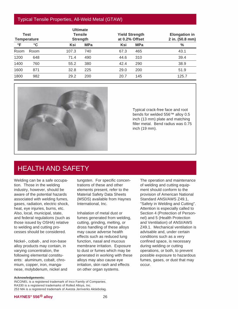
Typical crack-free face and rootbends for welded 556™ alloy 0.5inch (13 mm) plate and matchingfiller metal. Bend radius was 0.75inch (19 mm).
HAYNES® 556TM alloy27
HAYNES® 556™ alloy is similarin machining characteristics toother solid-solution-strength-ened nickel-base alloys. Thesealloys as a group are classifiedas moderate to difficult to
machining are to use lowerspeeds and feeds, and to takeheavier cuts than would beused for machining stainlesssteels. See Haynes Interna-tional publication H-3159 formore detailed information.
Use carbide C-2 / C-3 grade tool
Speed: 90 surface feet / minuteFeed: 0.010 in. / revolutionDepth of cut: 0.150 in.
Finishing (Turning / Facing)
Use carbide C-2 / C-3 grade tool
Speed: 95-110 surface feet / minuteFeed: 0.005-0.007 in. / revolutionDepth of cut: 0.040 in.
Use high speed steel M-33 / M-40 series6/ orT-15 grades*
Speed: 10-15 surface feet / minute (200 RPMmaximum for 1/4 in. diameter or smaller)
Lubricant: oil or water-base. Use coolant feeddrills if possible.
MACHININGmachine; however, it should beemphasized that they can bemachined using conventionalmethods at satisfactory rates.As these alloys will work-hardenrapidly, the keys to successful
Normal Roughing (Turning / Facing)
Negative rake square insert, 45° SCEA'1/32 in. nose radius. Tool holder: 5° negativeback and side rakes.
Lubricant: Dry2, oil3 or water-base4,5.
Positive rake square insert, if possible,45° SCEA' 1/32 in. nose radius. Tool holder:5° positive back and side rakes.
Lubricant: Dry or water-base.
Drilling
Short, heavy-web drills with 135° crank shaftpoint. Thinning of web at point may reducethrust.
Feed:0.001 in. rev. 1/8 in. dia.0.002 in. rev. 1/4 in. dia.0.003 in. rev. 1/2 in. dia.0.005 in. rev. 3/4 in. dia.0.007 in. rev. 1 in. dia.
*Carbide drills not recommended, but may be used in some set-ups. See Haynes International publication H-3159 for details.
Notes: 1 SCEA - Side cutting edge angle, or lead angle of the tool.
2 At any point where dry cutting is recommended, an air jet directed on the tool may providesubstantial tool life increases. A water-base coolant mist may also be effective.
3 Oil coolant should be a premium quality, sulfochlorinated oil with extreme pressure additives.A viscosity at 100°F of from 50 to 125 SSU is standard.
4 Water-base coolant should be a 15:1 mix of water with either a premium quality, sulfochlorinatedwater soluble oil or a chemical emulsion with extreme pressure additives.
5 Water-base coolants may cause chipping or rapid failure of carbide tools in interrupted cuts.
6 M-40 series High Speed Steels include M-41 through M-46 at time of writing, others maybe added, and should be equally suitable.
STANDARD PRODUCTSBy Brand or Alloy Designation:
B-3®, C-4, C-22®, C-22HS®, C-276, C-2000®, G-30®, G-35®, G-50®, HYBRID-BC1™, and N
Corrosion-Wear Resistant AlloyULTIMET®
25, R-41, 75, HR-120®, HR-160®, HR-224™, 188, 214®, 230®, 230-W®, 242®, 263, 282®, 556®, 617, 625, 625SQ®, 718, X-750, MULTIMET®, NS-163™, and Waspaloy
Wear-Resistant Alloy
Ti-3Al-2.5V
HASTELLOY® High-Temperature Alloys
HASTELLOY® Corrosion-Resistant Alloys
S, W, and X
HAYNES® High-Temperature Alloys
6B
HAYNES® Titanium Alloy Tubular
Properties Data: The data and information in this publication are based on work conducted principally by Haynes International, Inc. and occasionally supplemented by information from the open literature, and are believed to be reliable. However, Haynes does not make any warranty or assume any legal liability or responsibility for its accuracy, completeness, or usefulness, nor does Haynes represent that its use would not infringe upon private rights.
Any suggestions as to uses and applications for specific alloys are opinions only and Haynes International, Inc. makes no warranty of results to be obtained in any particular situation. For specific concentrations of elements present in a particular product and a discussion of the potential health affects thereof, refer to the Material Safety Data Sheet supplied by Haynes International, Inc. All trademarks are owned by Haynes International, Inc.
Standard Forms: Bar, Billet, Plate, Sheet, Strip, Coils, Seamless or Welded Pipe & Tubing, Pipe Fittings, Flanges, Fittings, Welding Wire, and Coated Electrodes
052008
Global Headquarters1020 West Park Avenue
P.O. Box 9013Kokomo, Indiana 46904-9013 (USA)
Phone: 1-800-354-0806 or (765) 456-6012Fax: (765) 456-6905
For your local service center or sales offi ce, please call or visit our website.
www.haynesintl.com