Embed Size (px)
Citation preview

HASP Student Payload Application for 2015 Payload Title: Stratospheric Photography and Radio Impulse of Transient-Luminous Emissions Payload Class: (check one) x Small o Large
Institution: University of Calgary
Submit Date: December 18, 2014
Project Abstract The SPRITE (Stratospheric Photography and Radio Impulse of Transient-luminous Emissions) experiment is a small HASP payload proposed for launch on HASP in 2015. SPRITE will combine measurements of very low frequency (VLF) radio waves with images of transient luminous phenomena (TLEs) to measure the scattering of artificial VLF sources by TLEs. SPRITE is designed to be flown as a future 2U CubeSat mission, and to test a VLF receiver developed for the University of Calgary ABOVE2 high altitude flights to take place in 2016. Scientific objectives include the detection of sferics associated with sprites in order to identify variations in their radio signatures that may be related to differences in size, time-scale and morphology, and the investigation of the scattering of signals from terrestrial VLF radio transmitters by sprite radio emissions. The technical objectives are the testing of the VLF receiver at stratospheric altitudes and the development of a TLE imaging system suitable for deployment on a future CubeSat mission. Team Name:
SPRITE
Team or Project Website: ucalgary.ca/above/HASP
Student Team Leader Contact Information: Faculty Advisor Contact Information:
Name: Matthew Patrick Christopher Cully
Department: Physics and Astronomy Physics and Astronomy
Mailing Address:
Dept. of Physics and Astronomy Science B, Room 628 2500 University Drive N.W. Calgary, AB, Canada
Dept. of Physics and Astronomy Science B, Room 631 2500 University Drive N.W. Calgary, AB, Canada
City, State, Zip code:
Calgary, Alberta, T2N 1N4 Calgary, Alberta, T2N 1N4
e-mail: [email protected] [email protected]
Office telephone:
1-403-220-6340 1-403-220-6088
Cell: 1-403-477-4395 1-403-807-3309
FAX: 1-403-289-3331 1-403-289-3331
Table of Contents
Payload Description……………………………………………………………………………….2 Requirement: Component of Flight in Darkness…………………………….……………2 Introduction and Motivation………………………………………………………………2 Scientific Objectives………………………………………………………………………3 Technical Objectives…………………………………………………………………....…3 System Level Overview………………………………………………………....………...6
Payload Instrumentation…………………………………………………………………………..6 VLF Receiver……………………………………………………………………………...6 Video Camera……………………………………………………………………………..9 Triggered Camera…………………………………………………………………………9 Magnetometer……………………………………………………………………………..9
Thermal Control………………………………………………………………………………….10 Risk Assessment and Management……………………………………………………………....10
Preliminary Thermal and Vacuum Testing Procedure……………………………...…....11 Preliminary Shock Testing Procedure……………………………………………….......11
Payload Specifications…………………………………………………………………………...12 Physical Dimensions………………..…………………………………………………....12 Footprint and Mounting……………………………………………………………….....12 Description of Hazardous Materials Onboard………………………………...………....12 Preliminary Payload Specification and Integration Plan (PSIP)……………………........12 Preliminary Flight Operation Plan (FLOP)........................................................................13 Power Budget…………………………………………………………………………….13 Telemetry Budget………………………………………………………………………...14 Mass Budget……………………………………………………………………………...15
Payload Operation………………………………………………………………………………..17 Team Structure and Management………………………………………………………………..17
Project Timeline………………………………………………………………………….17 List of Deliverables………………………………………………………………………19 Student Members………………………………………………………………………...20 Project Advisors………………………………………………………………………….21
Available Resources Facilities and Funding…………………………………………………...21 Technical Drawings and Schematics…………………………………………………………….24
1
Payload Description
Requirement: Component of Flight in Darkness Our objectives require that our payload is flown in dark conditions for at least part of the duration of HASP.
Introduction and Motivation Sprites are a form of electrostatic discharge that occur during electrical storms, similar to lightning. Unlike lightning, however, sprites occur at mesospheric altitudes, manifesting as sudden bursts of red light localized to regions a few tens of kilometers in scale [Fullekrug et al., 2006]. While they often correlate with lightning [Sao Sabbas et al., 2003], their relationship as well as the specific mechanisms that lead to the appearance of a sprite remain unknown. Sprites, along with other forms of upperatmospheric lightning, belong to a larger family known as Transient Luminous Events (TLEs). TLEs are accompanied by radio emissions, known as ‘sferics’, in the VeryLow Frequency (VLF) and ExtremelyLow Frequency (ELF) bands. Sprites in particular have been identified as an important part of the global electric circuit as they represent a means of charge transfer between the lower atmosphere and space [GordilloVazquez and Luque, 2010]. The small HASP payload proposed here, referred to as SPRITE (Stratospheric Photography and Radio Impulse of Transientluminous Emissions), will combine VeryLow Frequency (VLF) and ExtremelyLow Frequency (ELF) radio measurements with highresolution images and video of any TLEs that occur during the flight. The SPRITE payload is designed to be flown as a test for a potential future CubeSat mission, and to this end, is implemented within the size and mass constraints of that platform. A commercial offtheshelf (COTS) video camera oriented toward the horizon will obtain timecorrelated video of the entire flight, while a smaller camera will be triggered on VLF emissions associated with TLEs, and save highresolution still photos to nonvolatile memory for later recovery. This specialized camera will also be oriented towards the horizon so as to image TLEs against the blackness of space. The video camera provides a means to verify the operation of the triggering mechanism, and is not anticipated as a potential part of a future orbital mission due to telemetry constraints. The VLF/ELF receiver instrument (hereafter referred to as simply the VLF instrument), in addition to providing the trigger for the camera, will record a continuous time series in the band from 200 Hz to 40 kHz. The VLF instrument derives its heritage from a successfully deployed set of groundbased instruments known as ABOVE (Array for Broadband Observations of VLF/ELF Emissions,
2
www.ucalgary.ca/above). ABOVE is a 9site array of VLF instruments at remote sites across Western Canada. Five sites are currently deployed and operational. Each ABOVE instrument monitors electromagnetic emissions from 200 Hz to 75 kHz, with the scientific motivation of monitoring energetic particle precipitation and natural magnetospheric emissions. The VLF instrument for SPRITE will be reflown on a 2016 Canadian Space Agency set of handlaunched zero pressure stratospheric flights known as ABOVE2. Three launches are planned from near Saskatoon, Canada in the summer of 2016 with the scientific objective of studying energetic particle precipitation at higher latitudes. With this in mind, the proposed SPRITE payload for HASP is partly intended as a critical flight test for the VLF instrument to be flown later on ABOVE2.
Scientific Objectives Sprites are highly variable in both their spatial and temporal scale, with notable features such as tendrils often appearing in their morphology [Fullekrug et al., 2006]. One of SPRITE’s objectives is to detect sferics associated with sprites in order to identify variations in their radio signatures that may be related to differences in size, timescale and morphology. By calibrating the imaging system to trigger on highamplitude VLF/ELF emissions we aim to record nearby sprites and correlate characteristic sizes and shapes with specific radio wave signatures. Since other sources, such as lightning, also produce sferics that may trigger our imaging system, SPRITE’s datastorage has been designed to allow a large number of false triggers. SPRITE’s second objective is to investigate the scattering of signals from terrestrial VLF radio transmitters by spriteinduced ionization. The bottom Dlayer of the ionosphere is reflective to waves at VLF/ELF frequencies, and together with the surface forms an effective waveguide that allows these signals to be transmitted over great distances with little attenuation. The largescale ionization caused by TLEs can have a substantial impact on the characteristics of waves propagating within the Earthionosphere waveguide, and this effect has successfully been used as a method of locating sprites [Rodger and Dowden, 1998]. By monitoring the amplitude and carrier phase of distant US Navy transmitters in the 22 kHz 37 kHz range, we will be able to simultaneously observe these effects along with their associated TLEs. The carrier phase from the MSK (Minimum Shift Keyed) signals of candidate transmitters has been successfully analyzed on data from ABOVE.
Technical Objectives Deployment of the SPRITE payload will accomplish two main technical objectives:
3
● Testing of the University of Calgary VLF receiver design in the near space environment, for future deployment on ABOVE2, and other possible balloon or satellite missions
● Development of a specialized imaging system capable of capturing highresolution photographs of TLEs that could be deployed on a future CubeSat flight.
The VLF receiver that we propose to fly on SPRITE is a variation on the University of Calgary design for the groundbased ABOVE project. Five ABOVE VLF ground receivers are already deployed across western Canada, and are currently obtaining scientific data. The ABOVE2 sounding balloon flights, planned to begin in 2016, require the ABOVE VLF receiver to operate in the stratosphere for extended periods of time. The SPRITE payload will test a smaller, lighter version of the ABOVE VLF receiver and verify its operation before the ABOVE2 flights begin. Adapting the groundbased VLF receiver used in ABOVE project for high altitude flights represents a development goal that we are prepared to accomplish during the assembly of SPRITE, and that has immediate, practical applications to the planned research of the ABOVE group at the University of Calgary. The imaging system that will be developed for SPRITE is being designed to obtain still pictures and video of any TLEs that occur in the vicinity of the HASP flight. When completed, it will consist of two main components:
● A specialized, triggered camera ● A consumer type video camera, currently planned to be a GoPro Hero 3 White Edition
The purpose of the video camera is to record a reference video for the duration of the flight. This video will be recorded directly to an SD card and will be used in the postflight performance verification of the more complicated, triggered camera. In addition, the proposed recording mode has a resolution of 720p at 60 frames per second, and will provide a visually impressive result that we plan to use for outreach and student recruitment, supporting future nearspace and satellite missions at the University of Calgary. The triggered camera uses a rollingshutter mode of operation to obtain images with the high temporal resolution necessary for recording TLEs. Conventional CCD cameras integrate for a preset amount of time and record all pixels at once. This operation is too slow for our needs, and at high frame rates, generates a massive amount of data which cannot be easily stored and greatly exceeds the telemetry budget of any CubeSat mission. The rolling shutter technique used in our proposed triggered camera solves these problems by reading and clearing one horizontal line of CCD pixels at a time, while iterating over all horizontal lines continuously. This process occurs within microseconds, which is more than sufficient to temporally resolve any TLEs within the triggered cameras field of view. The rolling shutter technique produces aliasing between frames
4
since each frame is compiled in segments. However, for a rapid event such as a TLE, the temporal ambiguity caused by this effect can be removed by viewing all images saved in the buffer at the same time post flight. SPRITE will include software on the flight computer that is slaved to GPS time, and will save several frames together with timing information on trigger by the VLF receiver. The triggered camera will save individual frames to a buffer in the flight computer’s RAM. The buffer will only consist of a few frames to limit the RAM usage and telemetry volume. When triggered by a VLF signal from a TLE, the flight computer will save the buffer to memory, along with several subsequent frames, to ensure the complete capture of the event. Unlike high frame rate video recordings, image buffers saved this way are small enough to be downloaded from an orbiting CubeSat. The triggering algorithm will be based on finding peaks in the VLF data that have a large amplitude over a time duration comparable to that expected for a sferic. Since the images are stored to nonvolatile memory and recovered later, triggering on false positives is less of a concern than not triggering on real events. Consequently, we will use an adaptive trigger threshold. The amplitude threshold at which we trigger the imaging system will be automatically updated inflight to ensure triggering averages to at least once per minute, but no more than once per second (exact rates TBD). Groundbased tests in proximity to lightning will allow us to calibrate our triggering algorithm.
5
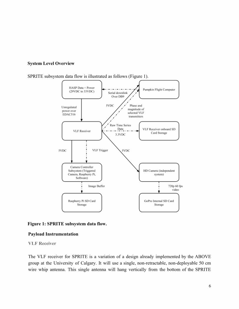
System Level Overview SPRITE subsystem data flow is illustrated as follows (Figure 1).
Figure 1: SPRITE subsystem data flow.
Payload Instrumentation
VLF Receiver The VLF receiver for SPRITE is a variation of a design already implemented by the ABOVE group at the University of Calgary. It will use a single, nonretractable, nondeployable 50 cm wire whip antenna. This single antenna will hang vertically from the bottom of the SPRITE
6
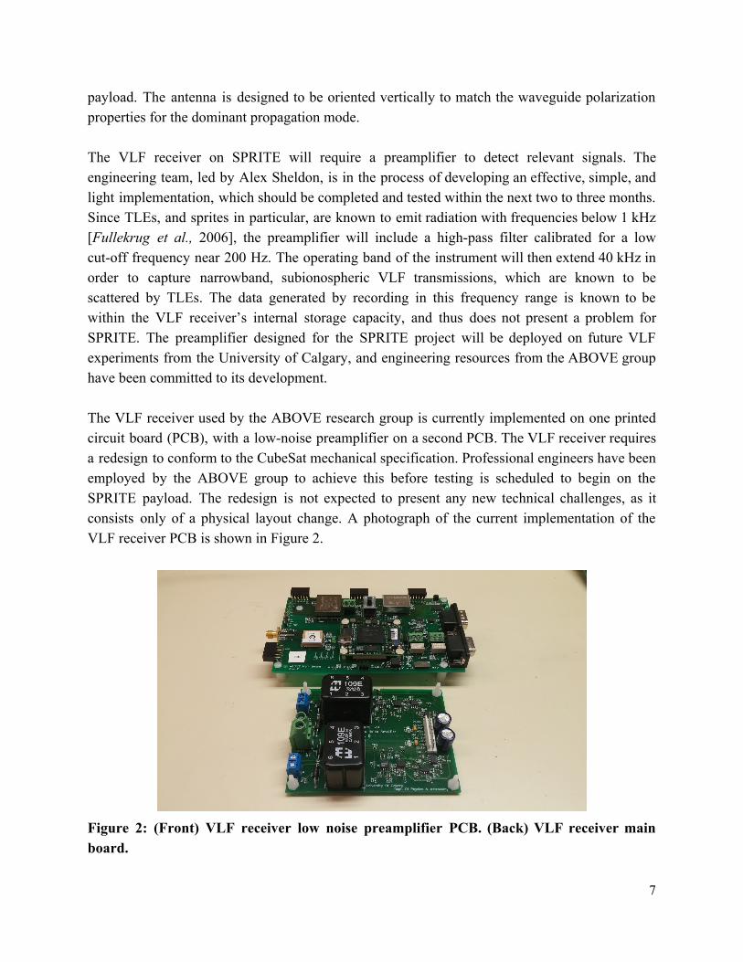
payload. The antenna is designed to be oriented vertically to match the waveguide polarization properties for the dominant propagation mode. The VLF receiver on SPRITE will require a preamplifier to detect relevant signals. The engineering team, led by Alex Sheldon, is in the process of developing an effective, simple, and light implementation, which should be completed and tested within the next two to three months. Since TLEs, and sprites in particular, are known to emit radiation with frequencies below 1 kHz [Fullekrug et al., 2006], the preamplifier will include a highpass filter calibrated for a low cutoff frequency near 200 Hz. The operating band of the instrument will then extend 40 kHz in order to capture narrowband, subionospheric VLF transmissions, which are known to be scattered by TLEs. The data generated by recording in this frequency range is known to be within the VLF receiver’s internal storage capacity, and thus does not present a problem for SPRITE. The preamplifier designed for the SPRITE project will be deployed on future VLF experiments from the University of Calgary, and engineering resources from the ABOVE group have been committed to its development. The VLF receiver used by the ABOVE research group is currently implemented on one printed circuit board (PCB), with a lownoise preamplifier on a second PCB. The VLF receiver requires a redesign to conform to the CubeSat mechanical specification. Professional engineers have been employed by the ABOVE group to achieve this before testing is scheduled to begin on the SPRITE payload. The redesign is not expected to present any new technical challenges, as it consists only of a physical layout change. A photograph of the current implementation of the VLF receiver PCB is shown in Figure 2.
Figure 2: (Front) VLF receiver low noise preamplifier PCB. (Back) VLF receiver main board.
7
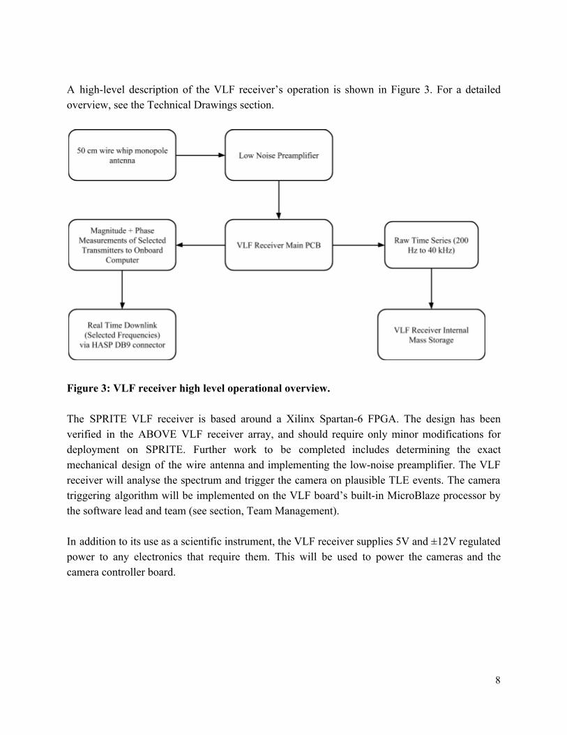
A highlevel description of the VLF receiver’s operation is shown in Figure 3. For a detailed overview, see the Technical Drawings section.
Figure 3: VLF receiver high level operational overview. The SPRITE VLF receiver is based around a Xilinx Spartan6 FPGA. The design has been verified in the ABOVE VLF receiver array, and should require only minor modifications for deployment on SPRITE. Further work to be completed includes determining the exact mechanical design of the wire antenna and implementing the lownoise preamplifier. The VLF receiver will analyse the spectrum and trigger the camera on plausible TLE events. The camera triggering algorithm will be implemented on the VLF board’s builtin MicroBlaze processor by the software lead and team (see section, Team Management). In addition to its use as a scientific instrument, the VLF receiver supplies 5V and ±12V regulated power to any electronics that require them. This will be used to power the cameras and the camera controller board.
8
Video Camera The video camera to be used on SPRITE is a GoPro Hero 3 White series. This camera was chosen because it is capable of recording 720p video at 60 frames per second to an internal 64 GB micro SD card. Relevant specifications follow.
● Resolution: 1280 x 720 ● Dimensions: 59 mm x 41 mm x 21 mm ● Mass: 74 Grams
Triggered Camera The triggered camera is a uEyeXS 2 [http://en.idsimaging.com/store/xs.html] . This camera was chosen partly because of its rolling shutter feature. As described in Technical Objectives, using a rolling shutter effectively eliminates problems with shutter lag. This greatly increases the chance of observing shortlived TLEs, and produces relatively little data that must be stored on the camera controller daughter board for the HASP flight or telemetered to the ground, as would be done for a future CubeSat mission. The uEyeXS 2 is designed to interface to a Raspberry Pi computer over USB 2.0, making it particularly easy to control through software. Relevant technical specifications follow.
● Sensor: Aptina CMOS Colour ● Resolution: 2592 x 1944 ● Dimensions: 26.5 mm x 23.0 mm x 21.5 mm ● Mass: 12 Grams ● Power/Interface: USB 2.0
Magnetometer The SPRITE camera controller daughter board design includes a HMC5883L 3Axis Digital Compass IC. This device will interface to the Raspberry Pi and provide camera orientation to within a few degrees when combined with measurements of the horizon angle from the video camera.
9
Thermal Control Our current thermal control plan is as follows:
● Insulate the outside of the CubeSat chassis ● Paint the exterior of the CubeSat chassis white to control thermal absorption ● Model the thermal environment using the Thermal Desktop software package
[http://www.crtech.com/thermaldesktop.html] ● Perform thermal testing at the University of Calgary as well as add heater tape and
thermostats if needed
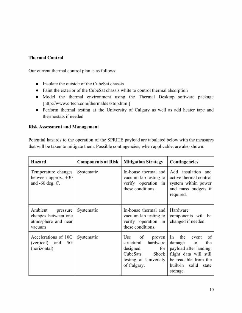
Risk Assessment and Management Potential hazards to the operation of the SPRITE payload are tabulated below with the measures that will be taken to mitigate them. Possible contingencies, when applicable, are also shown.
Hazard Components at Risk Mitigation Strategy Contingencies
Temperature changes between approx. +30 and 60 deg. C.
Systematic Inhouse thermal and vacuum lab testing to verify operation in these conditions.
Add insulation and active thermal control system within power and mass budgets if required.
Ambient pressure changes between one atmosphere and near vacuum
Systematic Inhouse thermal and vacuum lab testing to verify operation in these conditions.
Hardware components will be changed if needed.
Accelerations of 10G (vertical) and 5G (horizontal)
Systematic Use of proven structural hardware designed for CubeSats. Shock testing at University of Calgary.
In the event of damage to the payload after landing, flight data will still be readable from the builtin solid state storage.
10

Supply voltage fluctuations from approx. 33 to 29 VDC (as per payload interface manual)
Electrical VLF receiver onboard power regulation is designed to tolerate this variation.
In addition to the above, there is a nonzero chance that no TLEs will be observed by SPRITE during the HASP flight. The southwestern United States is known to have a sprite occurrence rate of approximately 190 per day in the early Fall [Sato and Fukunishi., 2003]. Given HASP’s altitude, the horizontally mounted cameras on SPRITE should be able to see for over 750 kilometers. For this reason, we believe it is reasonable to expect TLEs to be observed during the flight. We are assuming that at least part of the HASP flight occurs in darkness, so that TLEs can be observed. In the event that no TLEs are observed, SPRITE will still obtain useful data. In addition to achieving our technical objectives, VLF spectra will be obtained, aiding in ionospheric Dregion studies done using the ABOVE ground array. Regardless of TLE activity, the highresolution video camera will also record the flight and aid in future recruitment and outreach projects at the University of Calgary. A large part of our risk mitigation strategy is the development of a testing program using the inhouse thermal/vacuum facilities at the University of Calgary. Our group is in contact with Dr. David Knudsen, a faculty member who will be supervising and helping to coordinate our lab activities. Using these facilities, we can address the most likely problems before SPRITE is integrated during HASP Payload Integration.
Preliminary Thermal and Vacuum Testing Procedure The vacuum testing procedure is:
1. Evacuate the vacuum chamber to approximately 3 mb. 2. Power up payload and verify operation. 3. Operate payload for at least 1 hour, verifying data. 4. Increase pressure to match ambient.
The thermal testing procedure is:
1. Turn on the cooling system and soak until a temperature sensor, attached to an object with significant thermal mass, reaches 50 degrees C.
2. Wait approximately 2 hours, verify payload operation for at least 1 hour 3. Turn on heaters and soak until the same temperature sensor reaches +50 degrees C.
11
4. Wait approximately 2 hours, verify payload operation for at least 1 hour. 5. Decrease temperature to match ambient.
Each procedure will be repeated at least four times. Preliminary Shock Testing Procedure Shock testing will be performed at the University of Calgary to verify payload operation under 10 G vertical and 5 G horizontal accelerations. A mockup mounting plate will be constructed, and the completed, fullyoperational payload will be dropped from an appropriate distance to produce a 10 G acceleration on impact. A 5 G horizontal acceleration will be produced in the same manner. Full functional and performance testing will be conducted after each shock test. Payload Specifications
Physical Dimensions
SPRITE conforms to the 2U cubesat specification. See the relevant diagram in the Technical Drawings section.
Footprint and Mounting See the relevant mounting diagram in the Technical Drawings section.
Description of Hazardous Materials Onboard There are no hazardous materials included in SPRITE or any foreseen modification to its design. These include (as per the HASP call for proposals 2015):
● No radioactive materials ● No cryogenic materials ● No pressure vessels ● No high voltage ● No magnets ● No pyrotechnics ● No biological components ● No intentionally dropped components ● No environmental hazards
12
Preliminary Payload Specification and Integration Plan (PSIP) At this stage of the project, SPRITE has not yet been assembled. Physical measurements will be provided when assembly is completed and testing begins. Refer to the Technical Drawings section for dimensioned 2U cubesat mechanical drawings and mounting drawings. Preliminary shock testing and vacuum testing procedures were described in the preceding sections. Personnel participating in the testing program include, but are not limited to, those listed as team leaders in the Team Management section. It is currently expected that two team members will directly participate in integration at Palestine, Texas. SPRITE will be implemented such that it should require no intervention from our group when it is shipped to be integrated by HASP members. Preliminary Flight Operation Plan (FLOP)
There are no operations besides those specified in the HASP Interface Manual (T1h power up and power off prior to terminate) that will be required to be performed by HASP personnel. Any changes and developments will be documented in monthly reports submitted to HASP.
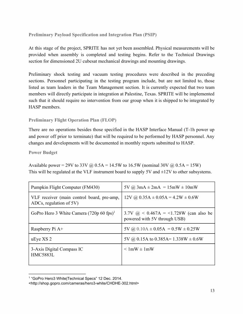
Power Budget Available power = 29V to 33V @ 0.5A = 14.5W to 16.5W (nominal 30V @ 0.5A = 15W) This will be regulated at the VLF instrument board to supply 5V and ±12V to other subsystems.
Pumpkin Flight Computer (FM430) 5V @ 3mA ± 2mA = 15mW ± 10mW
VLF receiver (main control board, preamp, ADCs, regulation of 5V)
12V @ 0.35A ± 0.05A = 4.2W ± 0.6W
GoPro Hero 3 White Camera (720p 60 fps) 1 3.7V @ < 0.467A = <1.728W (can also be powered with 5V through USB)
Raspberry Pi A+ 5V @ 0.10A ± 0.05A = 0.5W ± 0.25W
uEye XS 2 5V @ 0.15A to 0.385A= 1.338W ± 0.6W
3Axis Digital Compass IC HMC5883L
< 1mW ± 1mW
1 “GoPro Hero3 White|Technical Specs” 12 Dec. 2014. <http://shop.gopro.com/cameras/hero3white/CHDHE302.html>
13

Total 7.802W ± 1.461W
This power budget leaves room for an active thermal control system, if thermal and vacuum testing reveals that it is needed. Power regulation to the cameras, raspberry pi, and camera controller board is done onboard the VLF main board. Typical switching power supply efficiencies are approximately 90%, so this will not significantly alter our power budget.
Telemetry Budget Our data will be transmitted in a comma delimited string with a format as shown here: {HHMMSS, amplitude 1, phase 1, amplitude 2, phase 2 ,amplitude 3, phase 3, amplitude 4, phase 4, # of triggers, threshold, temperature, 5V monitor, 12V monitor, bearing}. The size of each of these fields is specified in the table below.
Time Stamp (HHMMSS) 6 bytes/s
Amplitude & phase of transmitter 1 (24.0kHz Cutler, Maine) 2 8 bytes/s
Amplitude & phase of transmitter 2 (24.8kHz Jim Creek, Washington)4 8 bytes/s
Amplitude & phase of transmitter 3 (25.2kHz La Moure, North Dakota)4 8 bytes/s
Amplitude & phase of transmitter 4 (37.5kHz Grindavik, Iceland)4 8 bytes/s
Number of triggers this second (12 bit number represented in hexadecimal) 3 bytes/s
Threshold (32 bit number represented in hexadecimal) 4 bytes/s
Temperature (8 bit ADC output represented in hexadecimal) 2 bytes/s
5V monitor (8 bit ADC output represented in hexadecimal) 2 bytes/s
12V monitor (8 bit ADC output represented in hexadecimal) 2 bytes/s
Bearing (in degrees 0 to 360) 3 bytes/s
Comma delimiting 14 bytes/s
Total 68 bytes/s
2 These will be transmitted as 64 bit complex numbers (32 bit real, 32 bit imaginary) encoded in hexadecimal <http://ieeexplore.ieee.org/xpl/articleDetails.jsp?arnumber=4610935&sortType%3Dasc_p_Sequence%26filter%3DAND%28p_Publication_Number%3A4610933%29>
14
The maximum allowed telemetry bandwidth is 1200 bits per second. Allowing for start and stop bits, this gives 120 bytes/s (120 ascii encoded characters per second), giving significant margin in this budget. We will not require the use of the analog downlink.
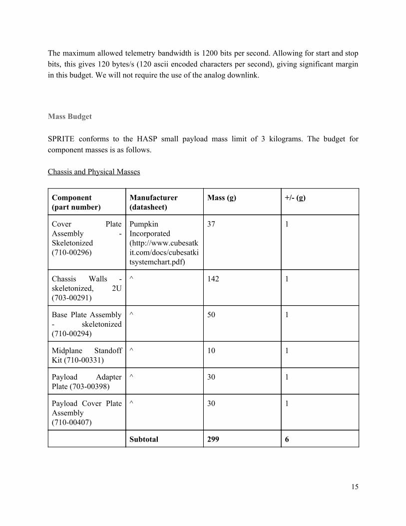
Mass Budget SPRITE conforms to the HASP small payload mass limit of 3 kilograms. The budget for component masses is as follows. Chassis and Physical Masses
Component (part number)
Manufacturer (datasheet)
Mass (g) +/ (g)
Cover Plate Assembly Skeletonized (71000296)
Pumpkin Incorporated (http://www.cubesatkit.com/docs/cubesatkitsystemchart.pdf)
37 1
Chassis Walls skeletonized, 2U (70300291)
^ 142 1
Base Plate Assembly skeletonized (71000294)
^ 50 1
Midplane Standoff Kit (71000331)
^ 10 1
Payload Adapter Plate (70300398)
^ 30 1
Payload Cover Plate Assembly (71000407)
^ 30 1
Subtotal 299 6
15
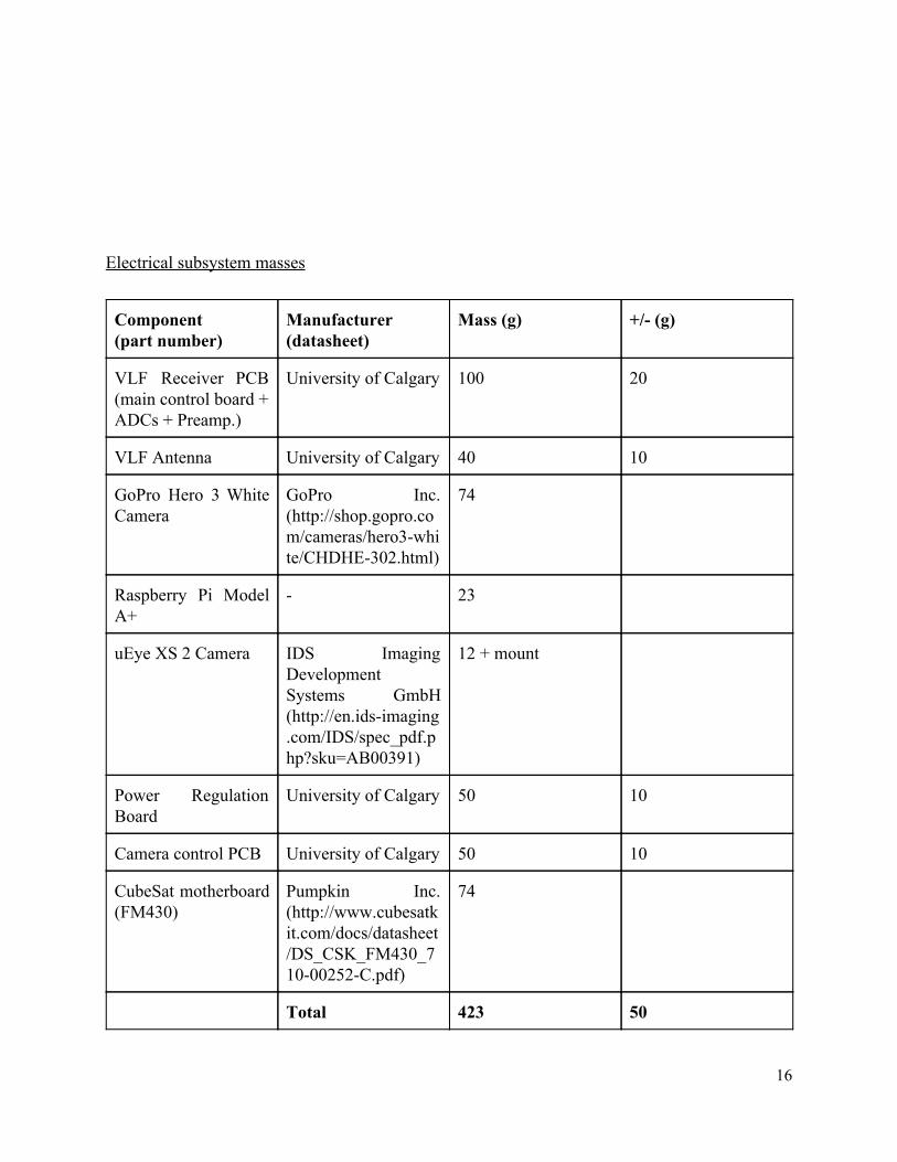
Electrical subsystem masses
Component (part number)
Manufacturer (datasheet)
Mass (g) +/ (g)
VLF Receiver PCB (main control board + ADCs + Preamp.)
University of Calgary 100 20
VLF Antenna University of Calgary 40 10
GoPro Hero 3 White Camera
GoPro Inc. (http://shop.gopro.com/cameras/hero3white/CHDHE302.html)
74
Raspberry Pi Model A+
23
uEye XS 2 Camera IDS Imaging Development Systems GmbH (http://en.idsimaging.com/IDS/spec_pdf.php?sku=AB00391)
12 + mount
Power Regulation Board
University of Calgary 50 10
Camera control PCB University of Calgary 50 10
CubeSat motherboard (FM430)
Pumpkin Inc. (http://www.cubesatkit.com/docs/datasheet/DS_CSK_FM430_71000252C.pdf)
74
Total 423 50
16
The projected total mass of 722 +/ 56 g is well within both the small HASP payload limit of 3 kilograms and the 2U cubesat weight limit of 2.66 kilograms. This leaves considerable room for any hardware changes that might need to occur during payload construction. The additional available mass helps mitigate one potential risk. In the event that SPRITE is found to require more power than the HASP specifications, it will be feasible to include an onboard battery. This is not anticipated to be required, but the option exists if needed.
Payload Operation SPRITE is designed to operate with minimal operations during flight. After power is provided at T1h, we anticipate that the payload will stay powered on until the payloadwide powerdown prior to terminate. Nominal operations should therefore consist of two commands: power on at T1h, and power off prior to terminate. No uplink is required over the serial link, and no notification is required prior to power off. The telemetry rate will be constant during the flight, and will be monitored for anomalies in realtime by the University of Calgary. In the event of an anomaly, a request to power cycle the payload will be made. Discrete commands: Power on, Power off
Team Structure and Management
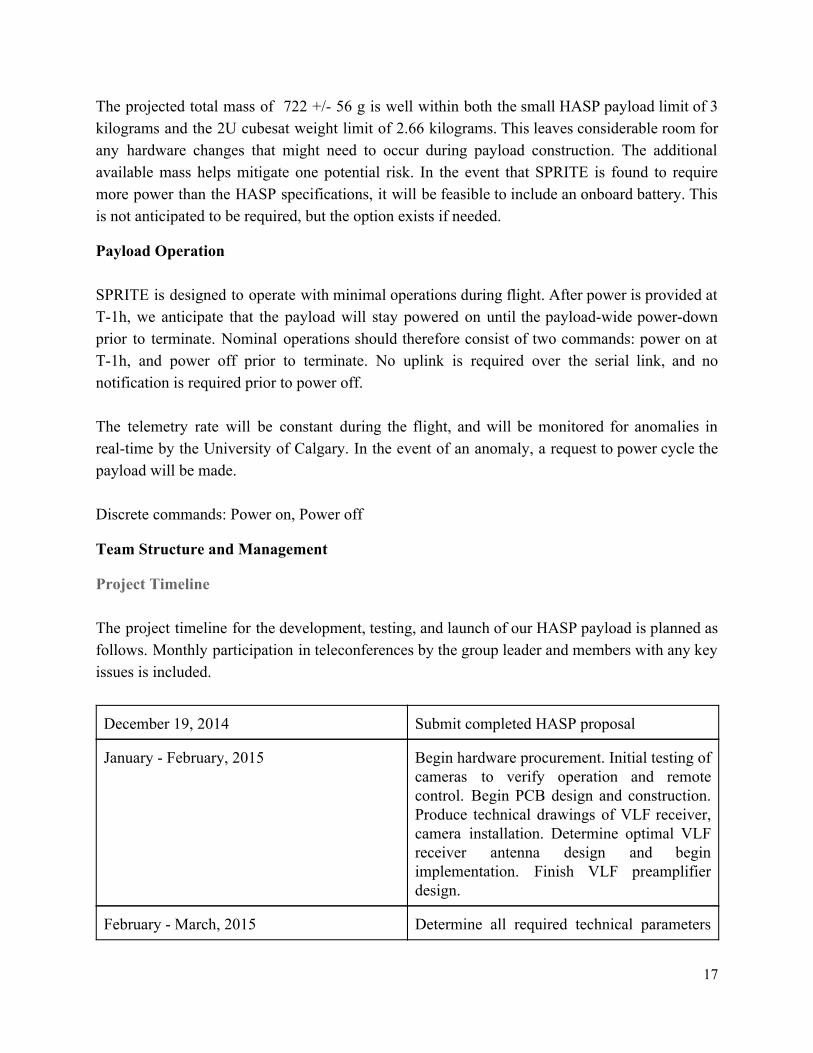
Project Timeline The project timeline for the development, testing, and launch of our HASP payload is planned as follows. Monthly participation in teleconferences by the group leader and members with any key issues is included.
December 19, 2014 Submit completed HASP proposal
January February, 2015 Begin hardware procurement. Initial testing of cameras to verify operation and remote control. Begin PCB design and construction. Produce technical drawings of VLF receiver, camera installation. Determine optimal VLF receiver antenna design and begin implementation. Finish VLF preamplifier design.
February March, 2015 Determine all required technical parameters
17
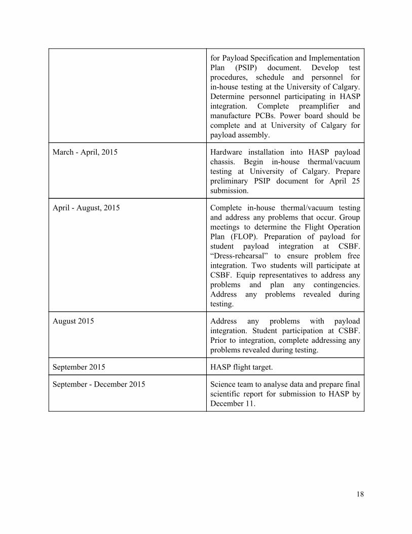
for Payload Specification and Implementation Plan (PSIP) document. Develop test procedures, schedule and personnel for inhouse testing at the University of Calgary. Determine personnel participating in HASP integration. Complete preamplifier and manufacture PCBs. Power board should be complete and at University of Calgary for payload assembly.
March April, 2015 Hardware installation into HASP payload chassis. Begin inhouse thermal/vacuum testing at University of Calgary. Prepare preliminary PSIP document for April 25 submission.
April August, 2015 Complete inhouse thermal/vacuum testing and address any problems that occur. Group meetings to determine the Flight Operation Plan (FLOP). Preparation of payload for student payload integration at CSBF. “Dressrehearsal” to ensure problem free integration. Two students will participate at CSBF. Equip representatives to address any problems and plan any contingencies. Address any problems revealed during testing.
August 2015 Address any problems with payload integration. Student participation at CSBF. Prior to integration, complete addressing any problems revealed during testing.
September 2015 HASP flight target.
September December 2015 Science team to analyse data and prepare final scientific report for submission to HASP by December 11.
18
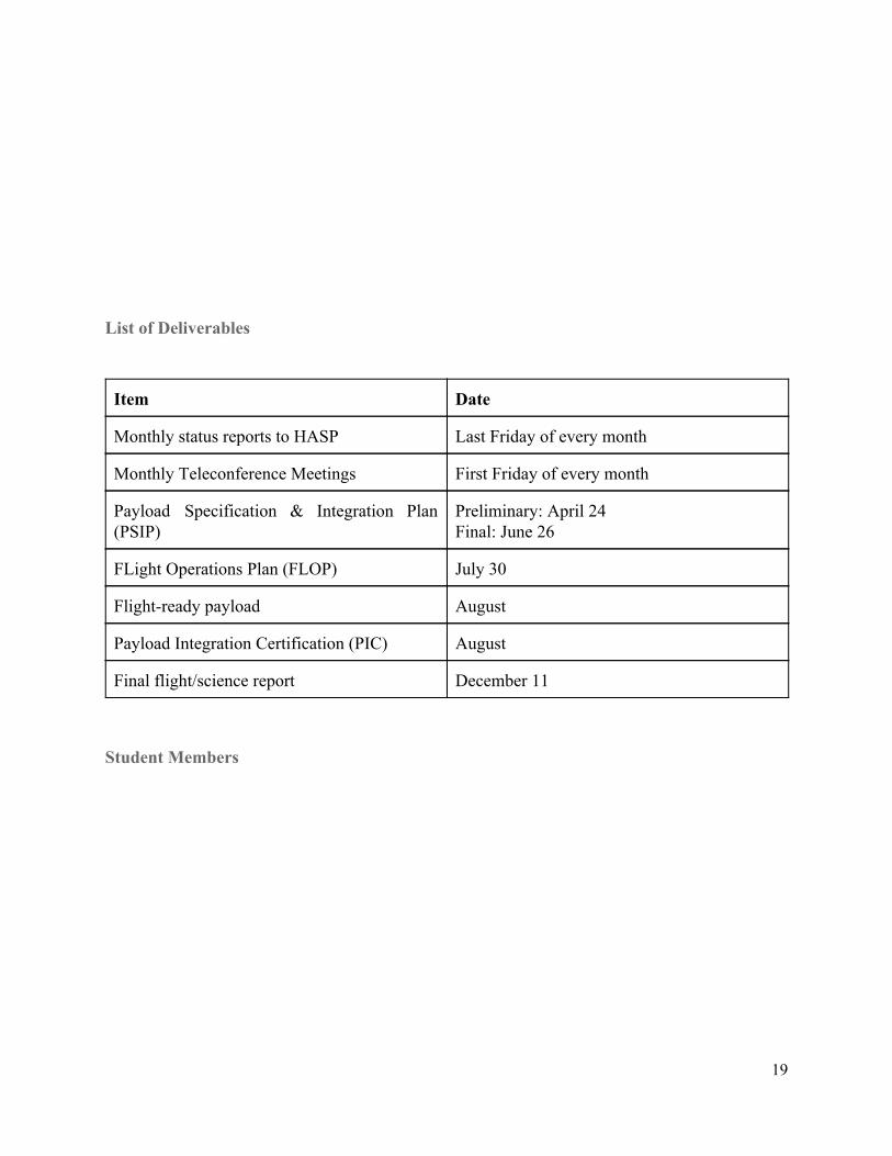
List of Deliverables
Item Date
Monthly status reports to HASP Last Friday of every month
Monthly Teleconference Meetings First Friday of every month
Payload Specification & Integration Plan (PSIP)
Preliminary: April 24 Final: June 26
FLight Operations Plan (FLOP) July 30
Flightready payload August
Payload Integration Certification (PIC) August
Final flight/science report December 11
Student Members
19
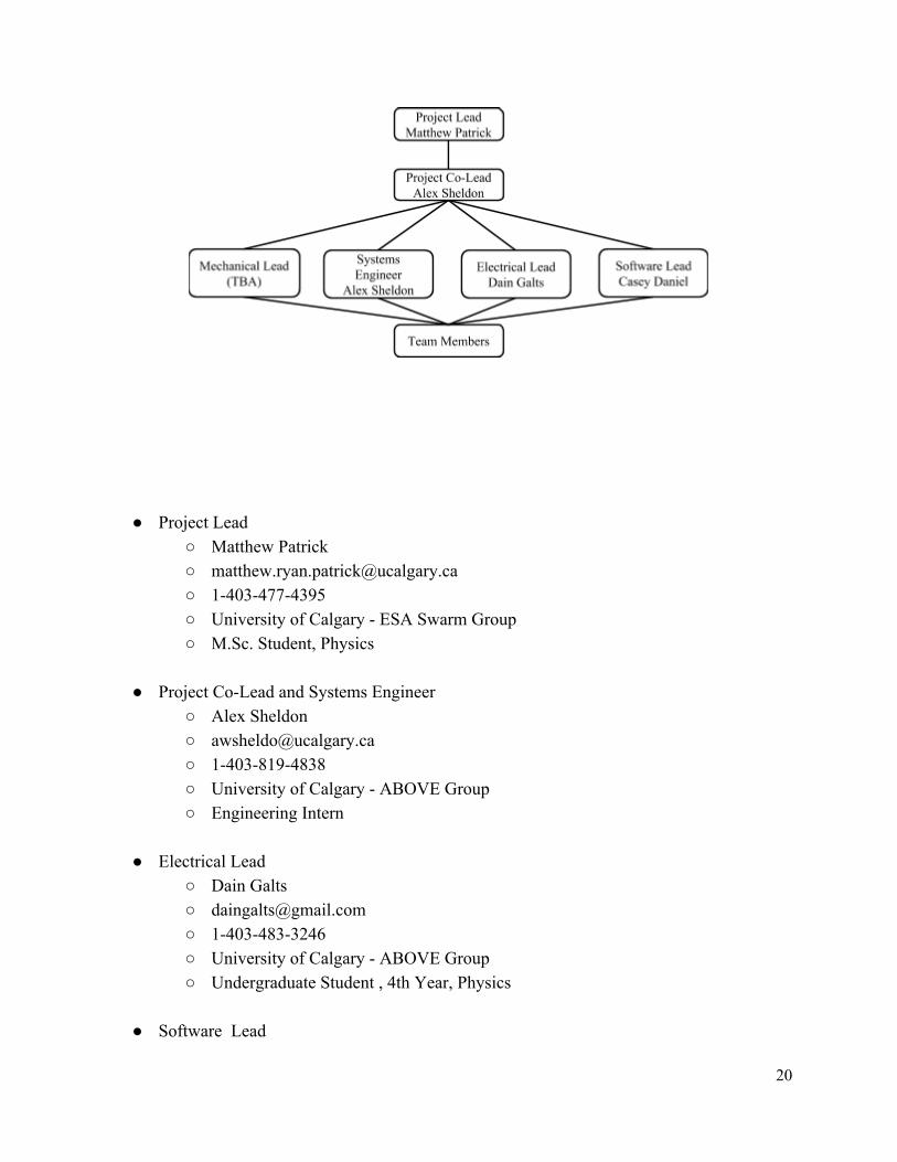
● Project Lead ○ Matthew Patrick ○ [email protected] ○ 14034774395 ○ University of Calgary ESA Swarm Group ○ M.Sc. Student, Physics
● Project CoLead and Systems Engineer
○ Alex Sheldon ○ [email protected] ○ 14038194838 ○ University of Calgary ABOVE Group ○ Engineering Intern
● Electrical Lead
○ Dain Galts ○ [email protected] ○ 14034833246 ○ University of Calgary ABOVE Group ○ Undergraduate Student , 4th Year, Physics
● Software Lead
20
○ Casey Daniel ○ [email protected] ○ 14039195908 ○ University of Calgary ABOVE Group ○ Undergraduate Student , 5th Year, Physics
These assignments are tentative and reflect the interests and experience of group members at the time of writing. Any changes will be done in communication with HASP and recorded in all relevant documentation submitted to the HASP project.
Project Advisors
● Professor Christopher Cully at the University of Calgary will be acting as the supervisor and main advisor for this project. As the leader of the ABOVE research group, he is our main point of contact for use of the VLF receiver.
● Professor David Knudsen at the University of Calgary will be supervising our inhouse thermal and vacuum testing.
● Dr. Laura Mazzino will be joining the ABOVE research group as a postdoctoral fellow in 2015. She has previously run successful HASP flights from the University of Alberta, and will be acting as an additional supervisor for our group. Dr. Mazzino has offered to help coordinate our interactions with the HASP project.
Available Resources Facilities and Funding The University of Calgary space physics group has proven testing facilities and recent heritage in testing and integration for spaceflight (CSA’s ePOP satellite: multiple instruments and overall payload, ESA’s Swarm satellites: instruments). The test facilities include general electronics laboratory space and equipment, cleanroom space, two midsized vacuum chambers and a thermal test chamber. We will be doing thermal and vacuum testing at the University of Calgary before delivery. Funding for SPRITE is available from several sources, with contingency funds available. Some of the major funding will be supplied through the Natural Sciences and Engineering Research
21
Council (NSERC) and the Canada Foundation for Innovation (CFI). Dr. Cully holds a Discovery Grant through NSERC to study electromagnetic wave propagation, and many of the expenses on this project are eligible under that grant. CFI is the major funding source for the ABOVE groundbased instruments. In the final award for ABOVE, there is an amount set aside to transition the ABOVE instruments to a flightlike configuration. Many of the SPRITE expenses are therefore also eligible under that award. Both awards have sufficient resources to carry the project hardware costs. The camera hardware is not an eligible expense for the NSERC or CFI funding. These costs can be paid out of Dr. Cully’s startup funding from the University of Calgary. Summer salary funding has not been fully finalized, although several positions are funded (one graduate student and two undergraduates). For any other students, there are two major competitions that could fund summer salaries: the NSERC Undergraduate Student Research Awards (USRA) and the University of Calgary’s Program for Undergraduate Research Experience (PURE). Both have application deadlines in the spring, and both programs (especially PURE) have a good likelihood of funding students for SPRITE.
Item Cost Funding source Status
Mechanical structure, onboard computer, realtime OS: Pumpkin CubeSat Kit /MSP430, skeletonized, 2U
$8375
Canada Foundation for Innovation (CFI), ABOVE project
Award conferred. PI: Cully. Item explicitly included in text of finalized grant, but final eligibility TBC.
VLF instrument boards, including engineering costs for flight modifications
$8000 Canada Foundation for Innovation (CFI), ABOVE project
Award conferred. PI: Cully. Eligible cost.
Triggered camera, including Raspberry Pi and mounting
$1000 University of Calgary, Startup funds
Award conferred. PI: Cully. Eligible cost.
Video camera $200 University of Calgary, Startup funds
Award conferred. PI: Cully. Eligible cost.
22
Misc. integration and test expenses
$2000 Canada Foundation for Innovation (CFI), ABOVE project, University of Calgary, Startup funds
Award conferred. PI: Cully. Eligible cost.
Travel to integration and test
$4000 Natural Sciences and Engineering Research Council (NSERC), Discovery Grant
Award conferred. PI: Cully. Eligibility TBC.
Travel to launch $3000 Natural Sciences and Engineering Research Council (NSERC), Discovery Grant
Award conferred. PI: Cully. Eligibility TBC.
Summer salary, undergraduate #1
$10,000 Mitacs Award conferred. PI: Cully. Eligible cost.
Summer salary, undergraduate #2
$10,000 Natural Sciences and Engineering Research Council (NSERC), Discovery Grant
Award conferred. PI: Cully. Eligible cost.
Summer salary, undergraduate #3,4
$10,000 NSERC USRA program and/or University of Calgary PURE program
Applications due in the winter term.
Summer salary, graduate student #1
$10,000 Natural Sciences and Engineering Research Council (NSERC), Discovery Grant
Award conferred. PI: Cully. Eligible cost.
23

Technical Drawings and Schematics
uEyeXS 2 Triggered Camera Physical Specification
source: IDS Imaging Development Systems (http://storeen.idsimaging.com/IDS/spec_pdf.php?sku=AB00391)
24
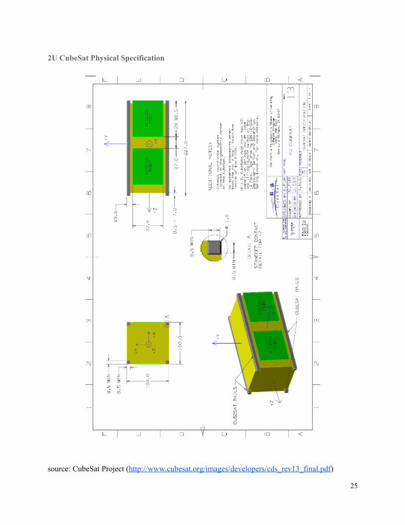
2U CubeSat Physical Specification
source: CubeSat Project (http://www.cubesat.org/images/developers/cds_rev13_final.pdf)
25
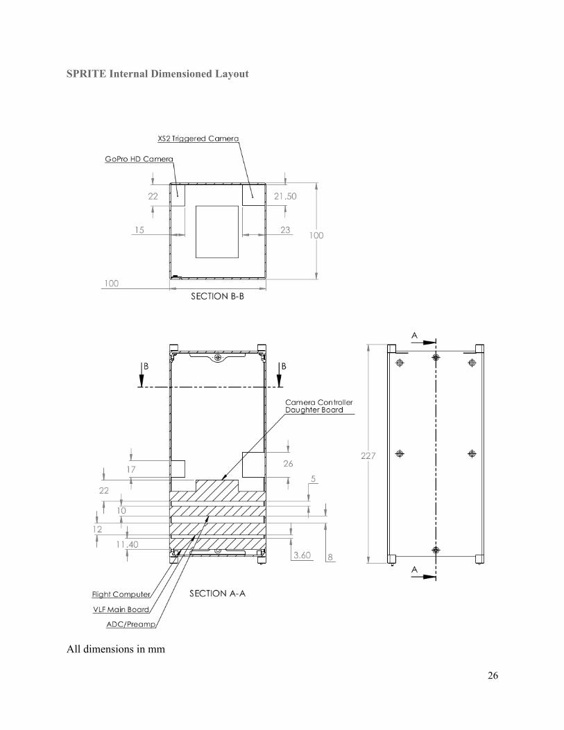
SPRITE Internal Dimensioned Layout
All dimensions in mm
26
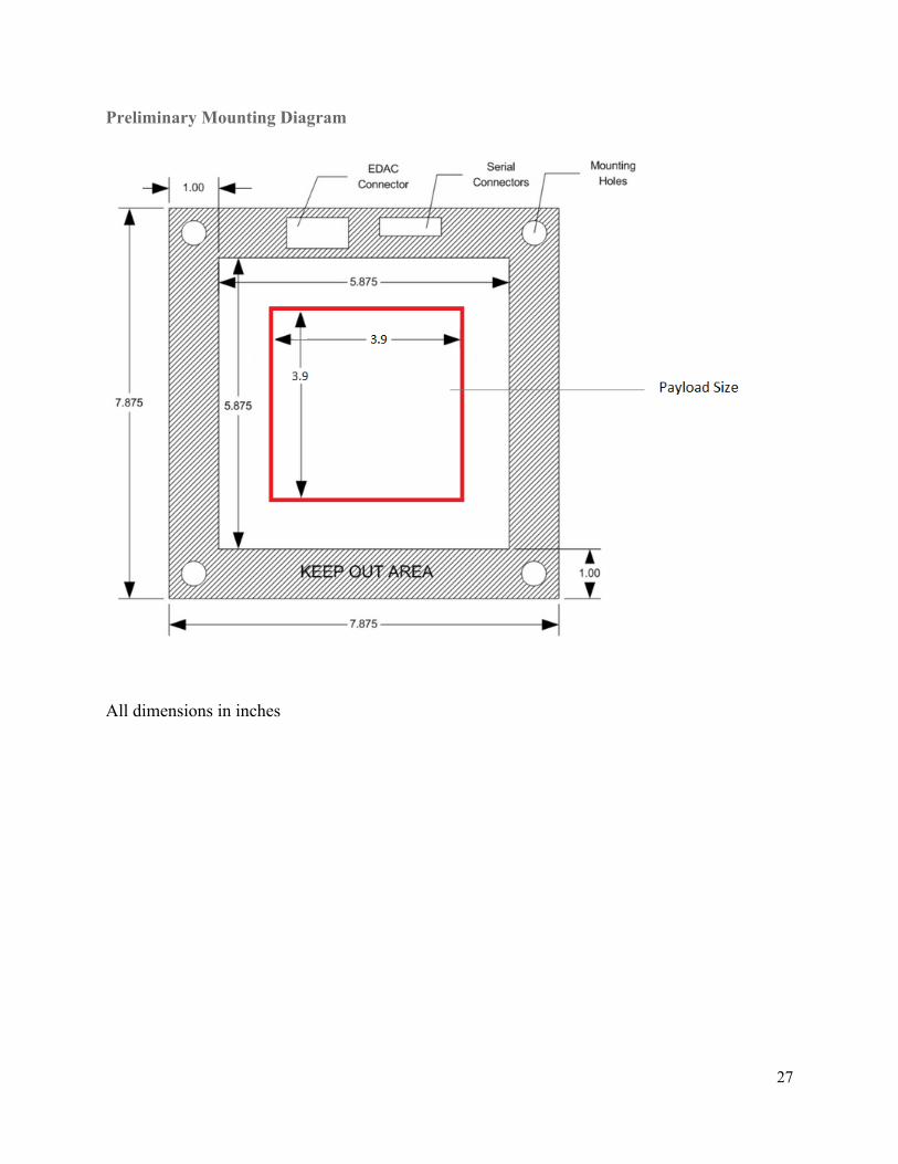
Preliminary Mounting Diagram
All dimensions in inches
27
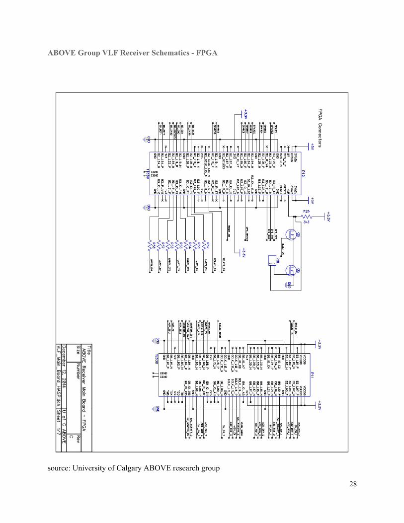
ABOVE Group VLF Receiver Schematics FPGA
source: University of Calgary ABOVE research group
28
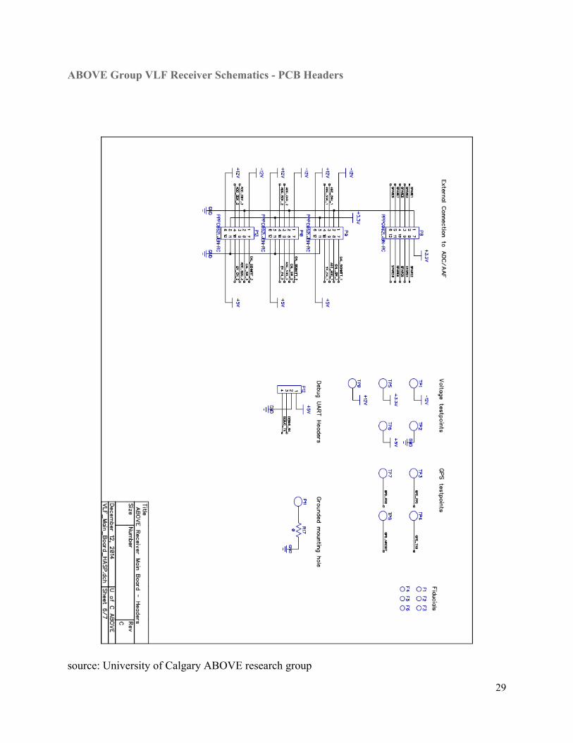
ABOVE Group VLF Receiver Schematics PCB Headers
source: University of Calgary ABOVE research group
29
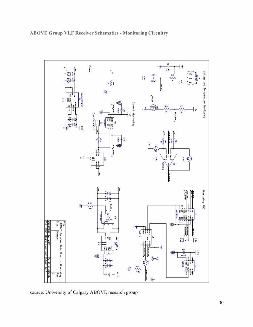
ABOVE Group VLF Receiver Schematics Monitoring Circuitry
source: University of Calgary ABOVE research group
30
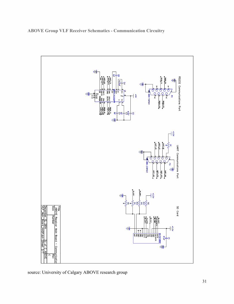
ABOVE Group VLF Receiver Schematics Communication Circuitry
source: University of Calgary ABOVE research group
31
References Fullekrug, M., E. A. Mareev, and M. J. Rycroft (2006), Sprites, Elves, and Intense Lightning Discharges, 810 pp., Springer, The Netherlands. GordilloVazquez, F. J. and A. Luque (2010), Electrical conductivity in sprite streamer channels, Geophys. Res. Lett., 37, L16809, doi: 10.1029/2010GL044349.
Rodger, C. J. and R. L. Dowden (1998), Position determination of red sprites by scattering of VLF subionospheric transmissions, Geophys. Res. Lett., 25(3), 281284. Sao Sabbas, F. T., D. D. Sentman, E. M. Wescott, O. Pinto, O. Mendes, M. J. Taylor (2003), Statistical analysis of spacetime relationships between sprites and lightning, J. Atmos. Sol.Terr. Phys., 65, 525535. Sato, M. and H. Fukunishi (2003), Global sprite occurrence locations and rates derived from triangulation of transient Schumann resonance events, Geophys. Res. Lett., 30(16), 1859.
32


![Hillside Agriculture Sub-Project [HASP]](https://img.pdfslide.us/doc/110x75/627b6d82bef92b7d1806c9de/hillside-agriculture-sub-project-hasp.jpg)