Embed Size (px)
Citation preview
HASP Student Payload Application for 2016
Payload Title: High Altitude Electrostatic Particle Collector
Payload Class: (check one) Small
Institution: College of the Canyons
Submit Date: 12/18/15
Project Abstract This proposal seeks to gain a small payload position on the 2016 HASP launch to capture and study passive Interplanetary Dust Particles (IDPs). The capture of IDPs for study has been primarily restrained to expensive long-duration high altitude flights, instrumentation on the International Space Station in orbit, or spacecraft trailing an active cometary coma. IDPs primarily originate from meteor showers and are collected in the form of smoke particles. Through the use of a high voltage electrostatic precipitator, passive IDPs of the full spectrum of size can be actively captured from the mid-to-upper stratosphere for further analysis. This method has never been used to capture IDPs and this experiment seeks to determine its effectiveness. All criteria of mass, power consumption, and structural support have been met according to HASP guidelines.
Team Name: N/A
Team or Project Website: N/A
Student Team Leader Contact Information: Faculty Advisor Contact Information:
Name: Daniel Tikhomirov Teresa Ciardi
Department: College of the Canyons Engineering
College of the Canyons Physics Department
Mailing Address:
560 Fairfield Rd 26455 Rockwell Canyon Rd
City, State, Zip code:
Simi Valley, CA, 93065 Santa Clarita, CA 91355
e-mail: [email protected] [email protected]
Office telephone:
(661) 287-5877
N/A
Cell: (661) 600-3270
N/A
FAX: N/A
N/A
Table of Contents
1. Science Instrumentation and Payload 1.1. Background 1.2. Hypothesis 1.3. Challenges
2. Payload Description 2.1. Structure
2.1.1. Materials 2.1.2. Stress Analysis
2.2. Electrostatic Particle Collector 2.2.1. Principle of Operation 2.2.2. Assembly
2.3. Flight Systems 2.3.1. Microcontroller 2.3.2. Data Logger 2.3.3. Motor Control 2.3.4. Altimeter
2.4. Power Management 2.5. High Voltage Circuit 2.6. Motor Operation
2.6.1. Control 2.6.2. Dynamics
2.7. Thermal Control System 2.7.1. Active Control 2.7.2. Passive Control
3. Team Structure 4. Timelines 5. HASP Integration
5.1. Mounting 5.2. Mass 5.3. Power Consumption 5.4. Downlink/Uplink Requirements 5.5. High Voltage Considerations
6. Preliminary Drawings 7. References
2
1. Science Instrumentation and Payload The College of The Canyons’ payload is designed to capture and trap Interplanetary Dust Particles (IDPs) using a concept derived from an electrostatic precipitator to negatively ionize particles and attract them to a positively charged plate. In 2014, Daniel Tikhomirov, the current project manager acted as chief engineer for the West Ranch High School weather balloon launch funded and led by Christine Hirst, M.S. One of the main payloads included in the launch was a device to passively capture IDPs through the use of silica aerogel. The principle of operation is similar to that of the current proposal payload: an opening airtight enclosure to collect particles and close at a designated time. The former design featured two 3Dprinted ABS plastic shells, one mounted to an aluminum base, and the other to a motorized lift arm. At a calculated time after launch, the top shell would be raised to expose the silica aerogel to the elements and timed to close before the balloon burst. The payload went through final assembly at the California State University Northridge cleanrooms that were available through collaboration with the physics department of CSUN. While the flight operation went as planned with the enclosure opening and closing at given altitudes, the samples were contaminated as the payload broke upon landing. The current payload design incorporates aircraftgrade aluminum construction to avoid the structural failure that caused the previous payload to fail. The scientific objectives of this experiment are to test the concept of electrostatic particle collection of highaltitude Interplanetary dust particles. The Electrostatic Particle Collector (EPC) is contained in a pressurized enclosure designed to be autonomously opened at 60,000ft by a motor via the onboard flight computer. The reason the High Altitude Student Platform is so necessary for experiment success is the flight duration and altitude. The HASP will ascend to a maximum altitude of 120,000ft, the ideal altitude within the stratosphere to capture passing IDPs. The duration of the flight ranges between 5 hours and 23 hours, giving the payload enough time to capture many more particles compared to a 1 hour latexballoon flight. 1.1 Background Interplanetary dust particles are the basic building blocks of comets, asteroids, and virtually all known terrestrial objects in the solar system. They range in size of a several microns to a few hundred nanometers and can normally only be visible through an electron microscope. Nearly 3000 tons of these particles, with an average daily flux of ~8 tons, enters our atmosphere every year and are believed to be the biggest contributors of organic materials to the earth. IDPs found in the upper stratosphere tend to originate from recent and current meteor showers in the form of smoke particles and ablated material. The conclusion to be drawn from this experiment, if successful, is that electrostatic particle collection is a new costeffective method for capturing IDPs without leaving the atmosphere. 1.2 Hypothesis
3

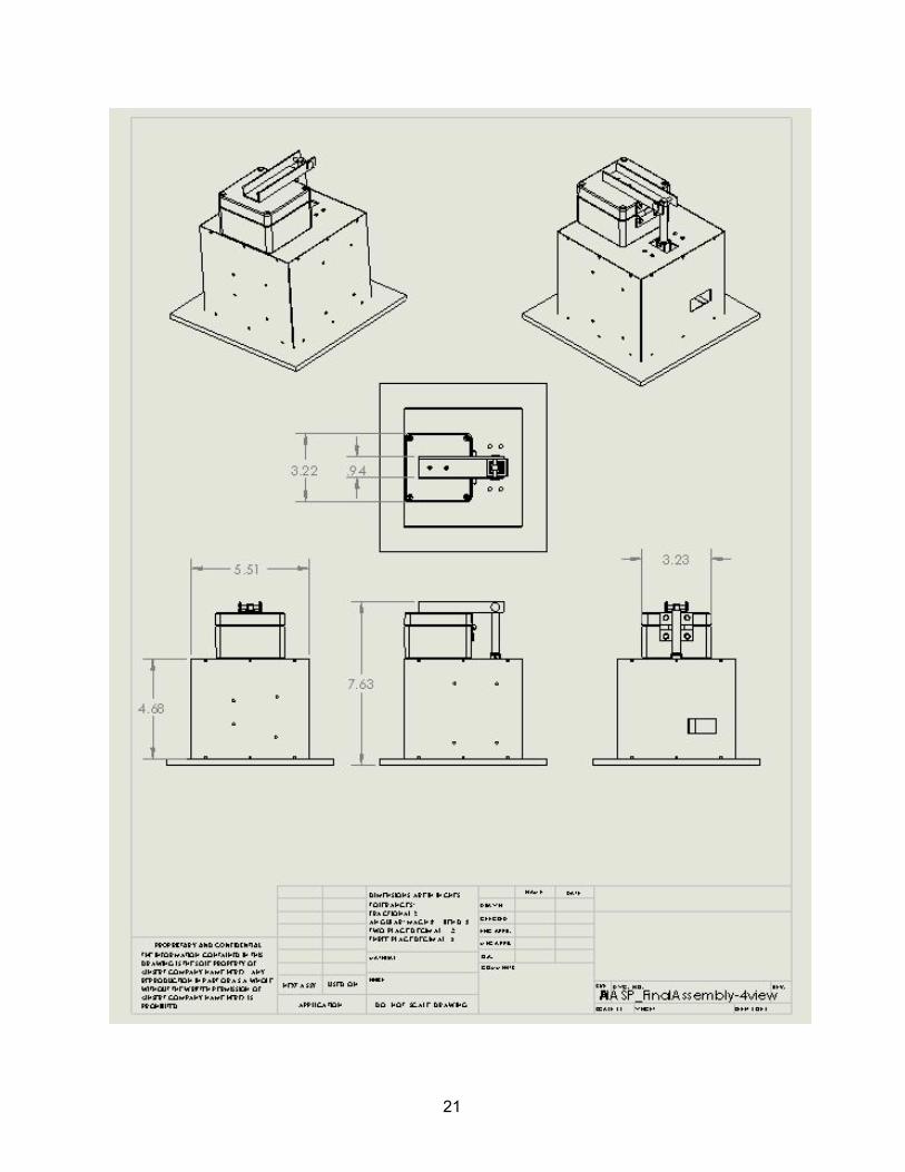
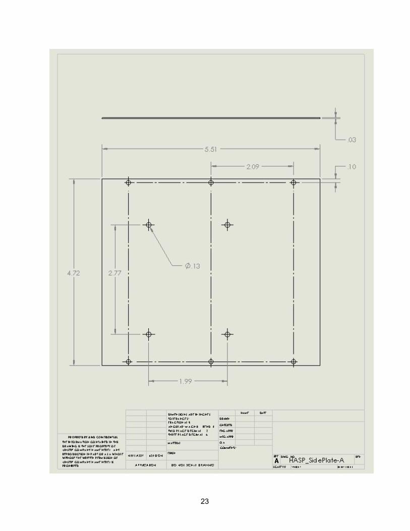
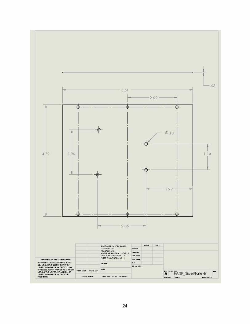
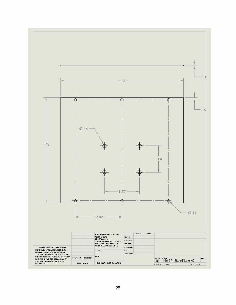
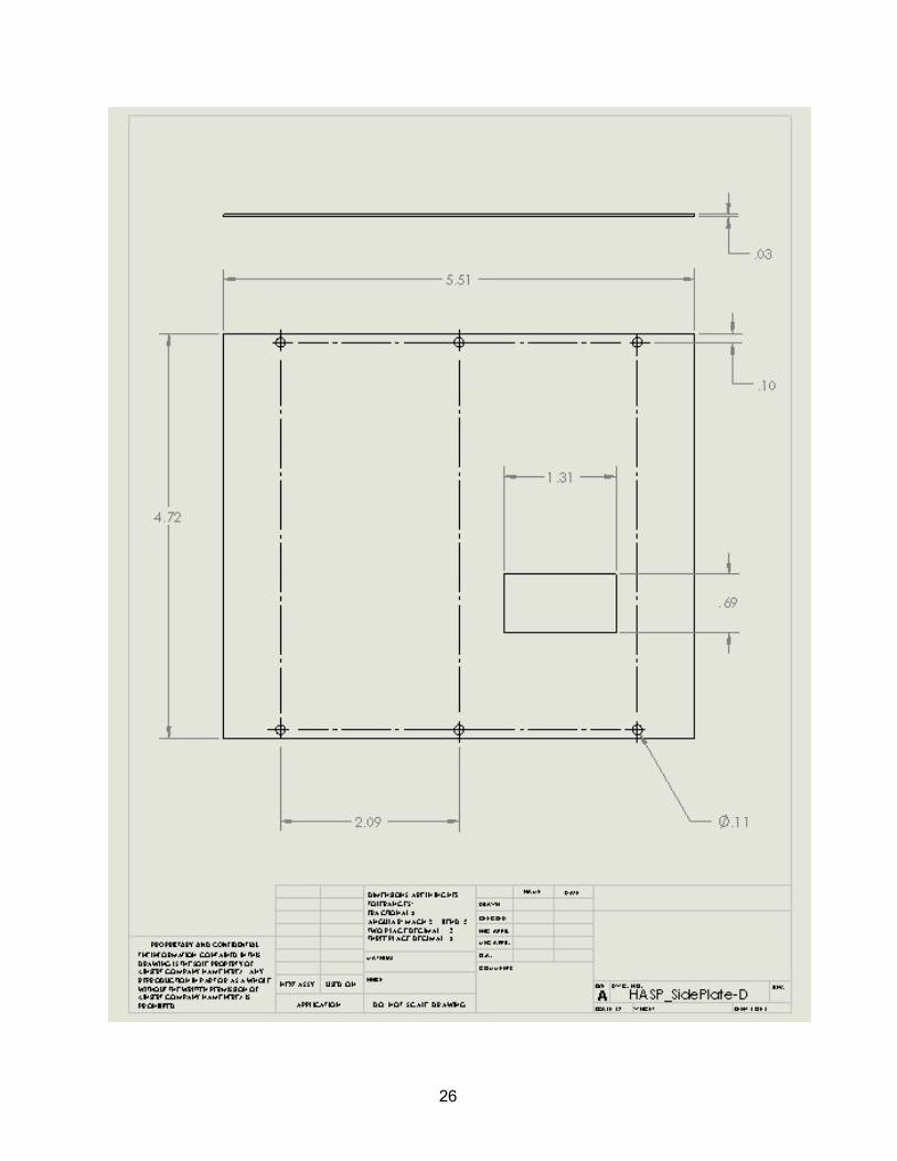
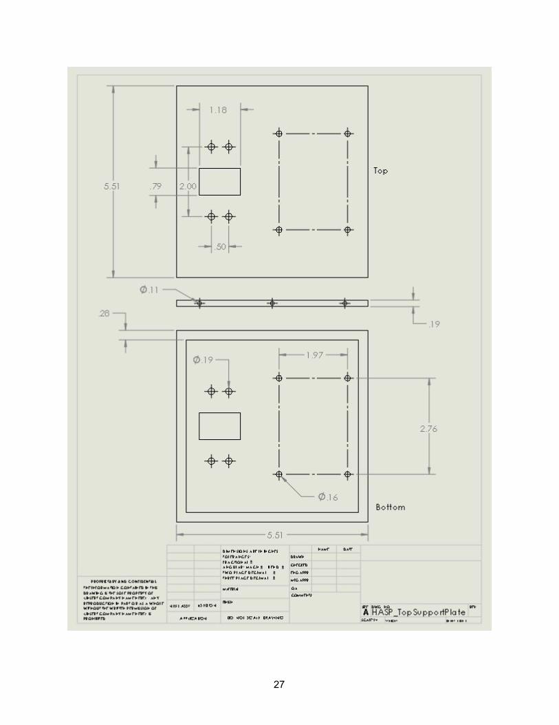
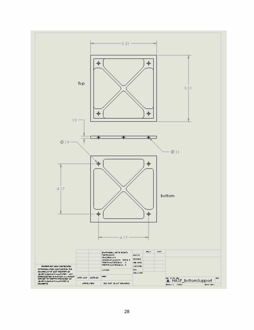
Current methods for IDP collection and analysis typically involve highvelocity particle impacts into fragile and brittle silica aerogel or passive particle collection by highaltitude aircraft with silicone oil collectors to trap smoke particles. Using an applied voltage of 10kV across a steel mesh and an applied voltage of +10kV across a copper plate, any particles passing through the steel mesh will become negatively ionized and become attracted to the copper plate. 1.3 Challenge The miniscule size and mass of IDPs are by far the greatest technical challenge to the experiment. They tend to be microns in size and nanograms in mass, making the particles are notoriously difficult to capture and analyze. Extreme care will be taken to ensure no particle contamination takes place in the cleanroom. High voltages will need to be applied with caution to avoid personal harm and damage to the electronics. Another challenge is the retrieval of particle samples from the copper plate upon sample return. One possible solution is to retrieve the copper plate from the enclosure, pour a transparent flexible epoxy over the sample to dry, and peel off the epoxy with the particles attached. The epoxy can then be cut up and analyzed through an optical microscope for larger particles and an electron microscope for smaller particles. 2. Payload Description The following sections will describe the construction, principle of operation, analysis, and design of every hardware element in the payload. 2.1 Structure The structure of the payload is a minimalist cube structure with most of the stress concentrated on the side panels and machine screws holding the panels to the top and bottom plates. The side panels are ~0.03 in (0.762mm) thick sheetaluminum with 6 machine screw holes for mounting to the top and bottom plates . The top plate is machined from ~0.19 in (4.826mm) thick aluminum with mounting holes for the motor and collector assembly . The bottom plate is machined from the same ~0.19 in (4.826mm) thick aluminum as the top plate, but with mounting holes for mating with the HASP interface plate . 2.1.1 Materials Side sheetaluminum panels will be constructed from high strength aluminum 2024 used for aircraft frames due to its high strength to weight ratio. Aluminum 2024 has a yield strength of 47,000 psi and a temperature rating of 320 degrees celsius. The high strength and resistance to cold temperatures is vital for longduration exposure and loadbearing while preserving weight. The top and bottom plates will be constructed from cheap, versatile, and machinable aluminum 6061. Aluminum 6061 has a yield strength of 35,000 psi and a temperature rating of 320 degrees celsius. The resistance to stresscracking at low temperatures makes this material ideal for use as a mounting base for the payload assembly.
4
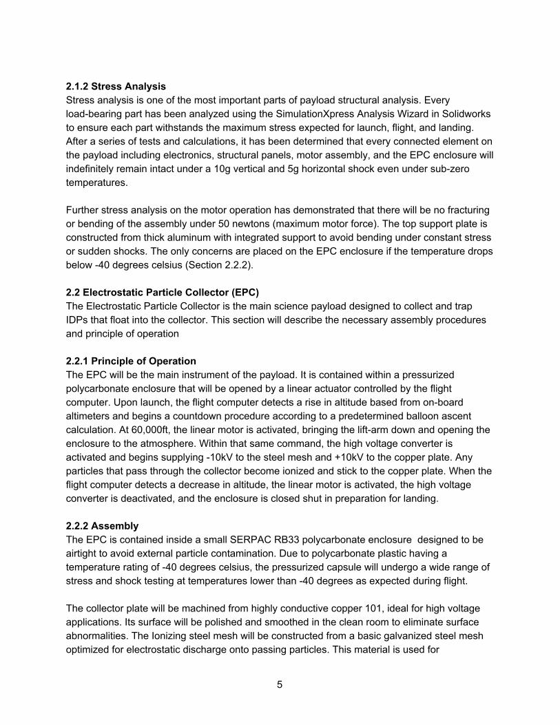
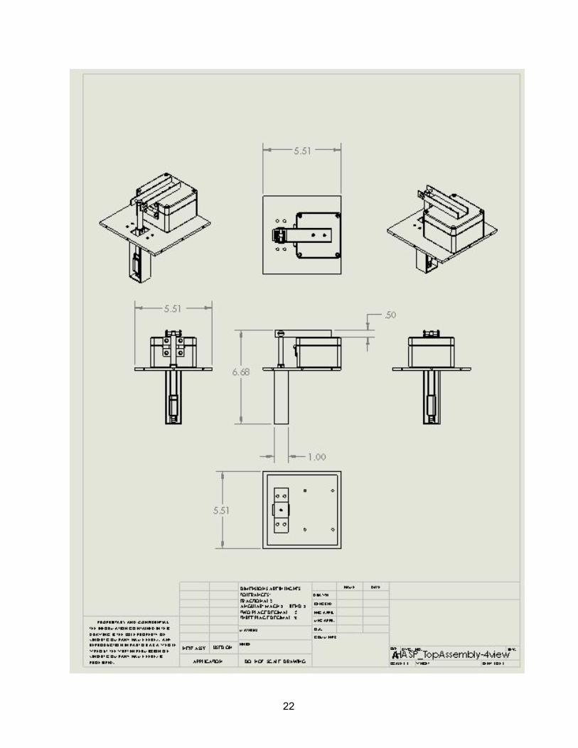
2.1.2 Stress Analysis Stress analysis is one of the most important parts of payload structural analysis. Every loadbearing part has been analyzed using the SimulationXpress Analysis Wizard in Solidworks to ensure each part withstands the maximum stress expected for launch, flight, and landing. After a series of tests and calculations, it has been determined that every connected element on the payload including electronics, structural panels, motor assembly, and the EPC enclosure will indefinitely remain intact under a 10g vertical and 5g horizontal shock even under subzero temperatures. Further stress analysis on the motor operation has demonstrated that there will be no fracturing or bending of the assembly under 50 newtons (maximum motor force). The top support plate is constructed from thick aluminum with integrated support to avoid bending under constant stress or sudden shocks. The only concerns are placed on the EPC enclosure if the temperature drops below 40 degrees celsius (Section 2.2.2). 2.2 Electrostatic Particle Collector (EPC) The Electrostatic Particle Collector is the main science payload designed to collect and trap IDPs that float into the collector. This section will describe the necessary assembly procedures and principle of operation 2.2.1 Principle of Operation The EPC will be the main instrument of the payload. It is contained within a pressurized polycarbonate enclosure that will be opened by a linear actuator controlled by the flight computer. Upon launch, the flight computer detects a rise in altitude based from onboard altimeters and begins a countdown procedure according to a predetermined balloon ascent calculation. At 60,000ft, the linear motor is activated, bringing the liftarm down and opening the enclosure to the atmosphere. Within that same command, the high voltage converter is activated and begins supplying 10kV to the steel mesh and +10kV to the copper plate. Any particles that pass through the collector become ionized and stick to the copper plate. When the flight computer detects a decrease in altitude, the linear motor is activated, the high voltage converter is deactivated, and the enclosure is closed shut in preparation for landing. 2.2.2 Assembly The EPC is contained inside a small SERPAC RB33 polycarbonate enclosure designed to be airtight to avoid external particle contamination. Due to polycarbonate plastic having a temperature rating of 40 degrees celsius, the pressurized capsule will undergo a wide range of stress and shock testing at temperatures lower than 40 degrees as expected during flight. The collector plate will be machined from highly conductive copper 101, ideal for high voltage applications. Its surface will be polished and smoothed in the clean room to eliminate surface abnormalities. The Ionizing steel mesh will be constructed from a basic galvanized steel mesh optimized for electrostatic discharge onto passing particles. This material is used for
5
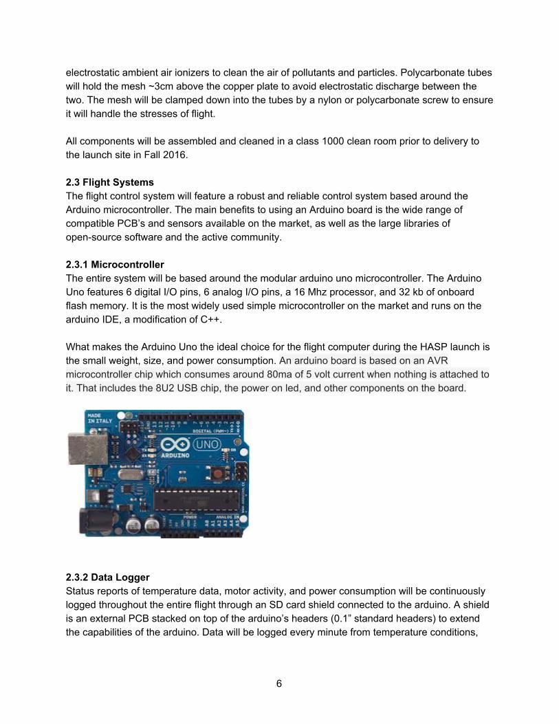
electrostatic ambient air ionizers to clean the air of pollutants and particles. Polycarbonate tubes will hold the mesh ~3cm above the copper plate to avoid electrostatic discharge between the two. The mesh will be clamped down into the tubes by a nylon or polycarbonate screw to ensure it will handle the stresses of flight. All components will be assembled and cleaned in a class 1000 clean room prior to delivery to the launch site in Fall 2016. 2.3 Flight Systems The flight control system will feature a robust and reliable control system based around the Arduino microcontroller. The main benefits to using an Arduino board is the wide range of compatible PCB’s and sensors available on the market, as well as the large libraries of opensource software and the active community. 2.3.1 Microcontroller The entire system will be based around the modular arduino uno microcontroller. The Arduino Uno features 6 digital I/O pins, 6 analog I/O pins, a 16 Mhz processor, and 32 kb of onboard flash memory. It is the most widely used simple microcontroller on the market and runs on the arduino IDE, a modification of C++. What makes the Arduino Uno the ideal choice for the flight computer during the HASP launch is the small weight, size, and power consumption. An arduino board is based on an AVR microcontroller chip which consumes around 80ma of 5 volt current when nothing is attached to it. That includes the 8U2 USB chip, the power on led, and other components on the board.
2.3.2 Data Logger Status reports of temperature data, motor activity, and power consumption will be continuously logged throughout the entire flight through an SD card shield connected to the arduino. A shield is an external PCB stacked on top of the arduino’s headers (0.1” standard headers) to extend the capabilities of the arduino. Data will be logged every minute from temperature conditions,
6
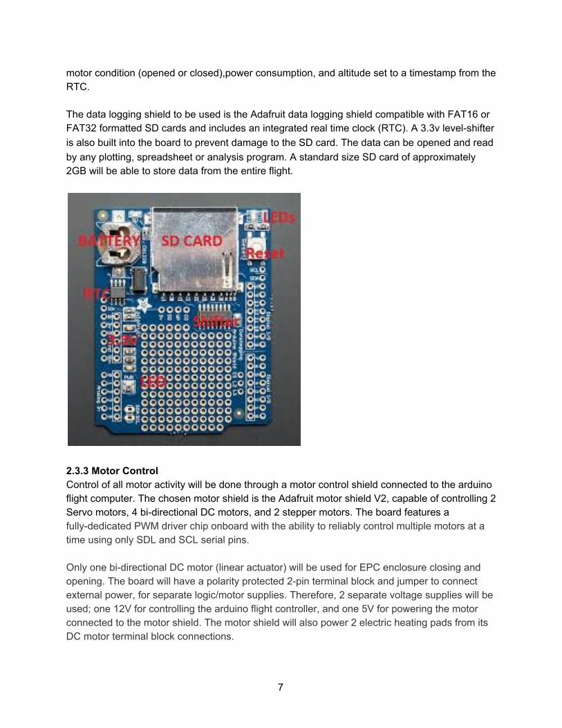
motor condition (opened or closed),power consumption, and altitude set to a timestamp from the RTC. The data logging shield to be used is the Adafruit data logging shield compatible with FAT16 or FAT32 formatted SD cards and includes an integrated real time clock (RTC). A 3.3v levelshifter is also built into the board to prevent damage to the SD card. The data can be opened and read by any plotting, spreadsheet or analysis program. A standard size SD card of approximately 2GB will be able to store data from the entire flight.
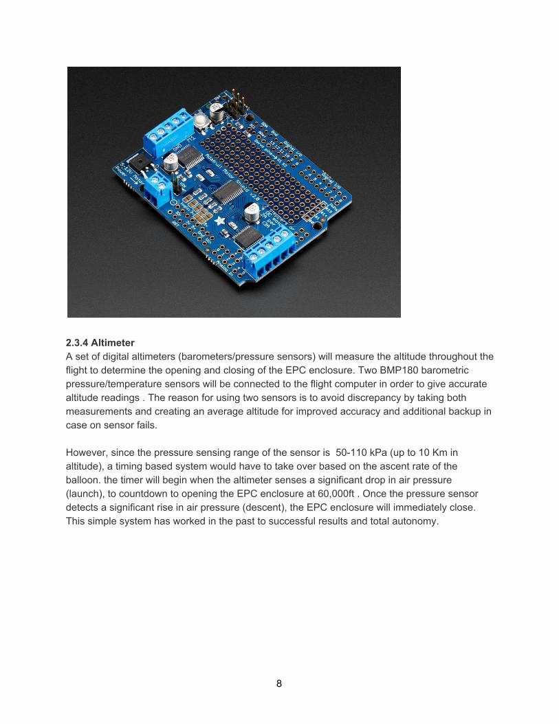
2.3.3 Motor Control Control of all motor activity will be done through a motor control shield connected to the arduino flight computer. The chosen motor shield is the Adafruit motor shield V2, capable of controlling 2 Servo motors, 4 bidirectional DC motors, and 2 stepper motors. The board features a fullydedicated PWM driver chip onboard with the ability to reliably control multiple motors at a time using only SDL and SCL serial pins. Only one bidirectional DC motor (linear actuator) will be used for EPC enclosure closing and opening. The board will have a polarity protected 2pin terminal block and jumper to connect external power, for separate logic/motor supplies. Therefore, 2 separate voltage supplies will be used; one 12V for controlling the arduino flight controller, and one 5V for powering the motor connected to the motor shield. The motor shield will also power 2 electric heating pads from its DC motor terminal block connections.
7
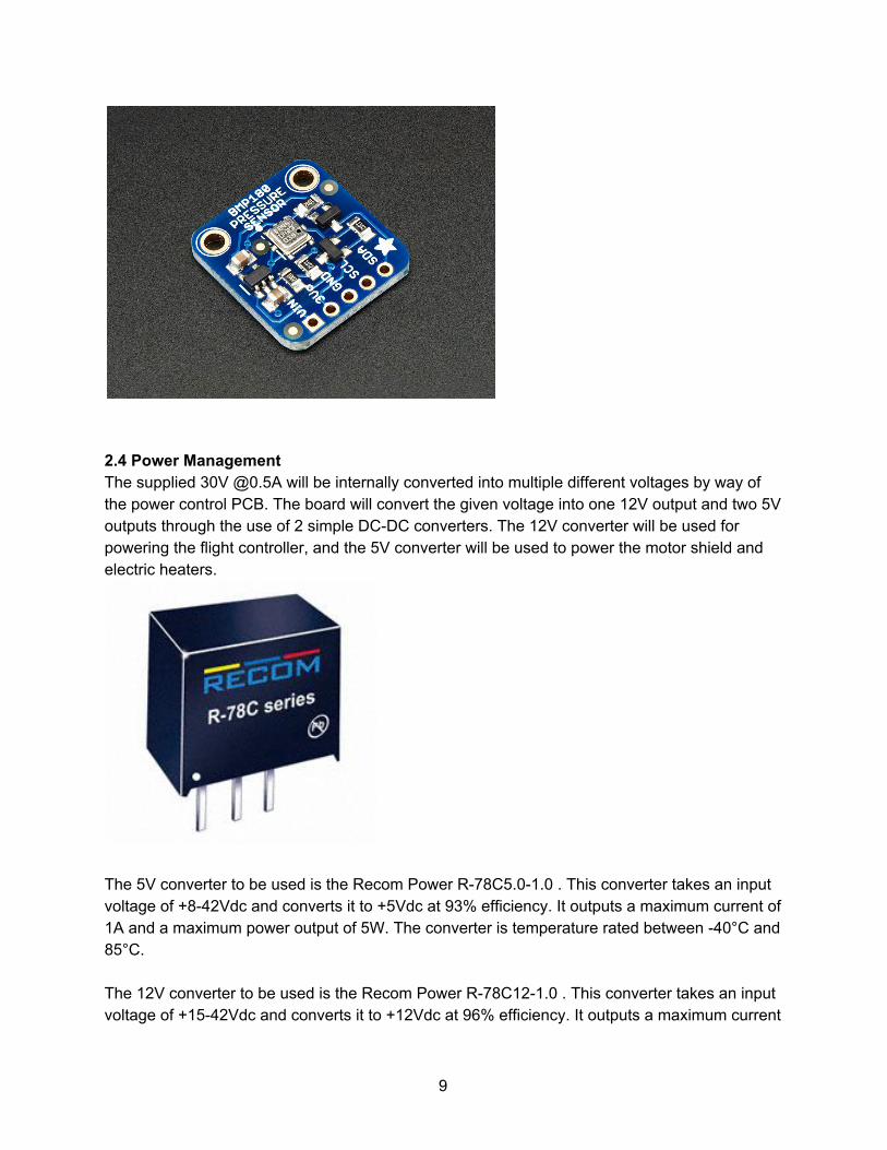
2.3.4 Altimeter A set of digital altimeters (barometers/pressure sensors) will measure the altitude throughout the flight to determine the opening and closing of the EPC enclosure. Two BMP180 barometric pressure/temperature sensors will be connected to the flight computer in order to give accurate altitude readings . The reason for using two sensors is to avoid discrepancy by taking both measurements and creating an average altitude for improved accuracy and additional backup in case on sensor fails. However, since the pressure sensing range of the sensor is 50110 kPa (up to 10 Km in altitude), a timing based system would have to take over based on the ascent rate of the balloon. the timer will begin when the altimeter senses a significant drop in air pressure (launch), to countdown to opening the EPC enclosure at 60,000ft . Once the pressure sensor detects a significant rise in air pressure (descent), the EPC enclosure will immediately close. This simple system has worked in the past to successful results and total autonomy.
8
2.4 Power Management The supplied 30V @0.5A will be internally converted into multiple different voltages by way of the power control PCB. The board will convert the given voltage into one 12V output and two 5V outputs through the use of 2 simple DCDC converters. The 12V converter will be used for powering the flight controller, and the 5V converter will be used to power the motor shield and electric heaters.
The 5V converter to be used is the Recom Power R78C5.01.0 . This converter takes an input voltage of +842Vdc and converts it to +5Vdc at 93% efficiency. It outputs a maximum current of 1A and a maximum power output of 5W. The converter is temperature rated between 40°C and 85°C. The 12V converter to be used is the Recom Power R78C121.0 . This converter takes an input voltage of +1542Vdc and converts it to +12Vdc at 96% efficiency. It outputs a maximum current
9
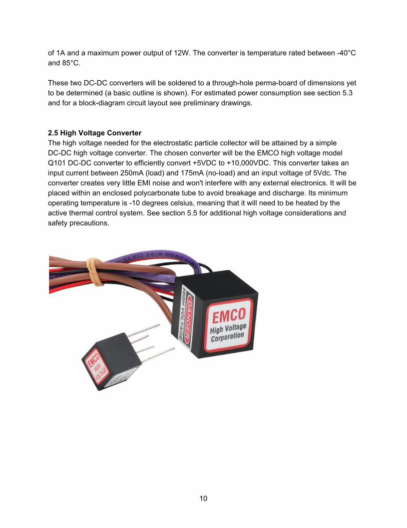
of 1A and a maximum power output of 12W. The converter is temperature rated between 40°C and 85°C. These two DCDC converters will be soldered to a throughhole permaboard of dimensions yet to be determined (a basic outline is shown). For estimated power consumption see section 5.3 and for a blockdiagram circuit layout see preliminary drawings. 2.5 High Voltage Converter The high voltage needed for the electrostatic particle collector will be attained by a simple DCDC high voltage converter. The chosen converter will be the EMCO high voltage model Q101 DCDC converter to efficiently convert +5VDC to +10,000VDC. This converter takes an input current between 250mA (load) and 175mA (noload) and an input voltage of 5Vdc. The converter creates very little EMI noise and won't interfere with any external electronics. It will be placed within an enclosed polycarbonate tube to avoid breakage and discharge. Its minimum operating temperature is 10 degrees celsius, meaning that it will need to be heated by the active thermal control system. See section 5.5 for additional high voltage considerations and safety precautions.
10
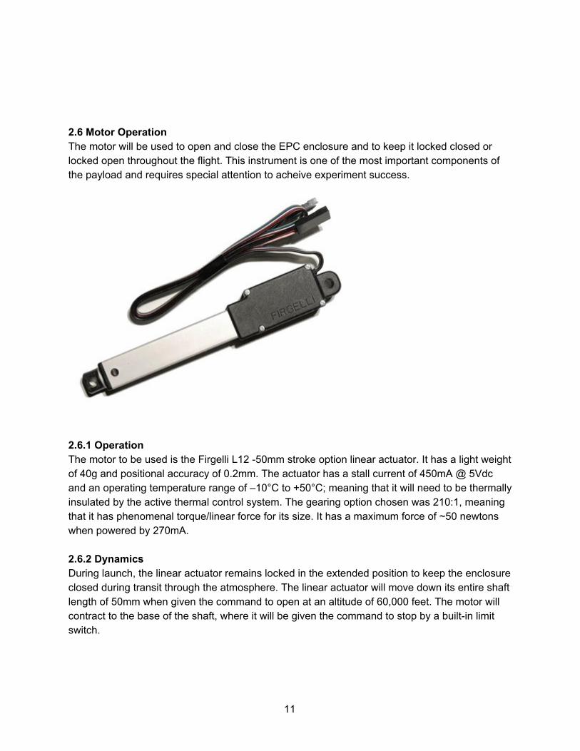
2.6 Motor Operation The motor will be used to open and close the EPC enclosure and to keep it locked closed or locked open throughout the flight. This instrument is one of the most important components of the payload and requires special attention to acheive experiment success.
2.6.1 Operation The motor to be used is the Firgelli L12 50mm stroke option linear actuator. It has a light weight of 40g and positional accuracy of 0.2mm. The actuator has a stall current of 450mA @ 5Vdc and an operating temperature range of –10°C to +50°C; meaning that it will need to be thermally insulated by the active thermal control system. The gearing option chosen was 210:1, meaning that it has phenomenal torque/linear force for its size. It has a maximum force of ~50 newtons when powered by 270mA. 2.6.2 Dynamics During launch, the linear actuator remains locked in the extended position to keep the enclosure closed during transit through the atmosphere. The linear actuator will move down its entire shaft length of 50mm when given the command to open at an altitude of 60,000 feet. The motor will contract to the base of the shaft, where it will be given the command to stop by a builtin limit switch.
11

During this motion, the enclosure will open on a hinge by approximately 60 degrees (216000 arcseconds, or 1.0472 radians) from the horizontal. This motion will not extend out beyond the 15 cm^2 (base) x 32 cm (height) exclusion zone for small payloads. The motor will remain contracted until given the command to extend once the altimeter measures a drop in altitude below 60,000 feet. After that point, the motor will extend 50mm fully shut the enclosure and ensure a pressurized seal. 2.7 Thermal Control System At longduration highaltitude flight, keeping electronics, moving parts, and load bearing elements at a controlled temperature is vital to mission success. This will be achieved through a passive and active thermal control system, monitored and logged by the flight computer. 2.7.1 Passive Thermal Control Passive thermal control will be achieved through extensive thermal insulation of the internal volume of the payload, motor assembly, and electrical systems. The insulative material to be used will be derived from NASA’s MultiLayerInsulation (MLI), which consists of multiple layers of metallized mylar (metallized polyethylene terephthalate) and fabric scrim separator. For thermal insulation of the internal volume of the payload, a combination of MLI, Kapton tape (polyimide film), and 3.5mm aerogel thermal blanket insulation. Kapton tape will cover the internal surface of the aluminum side panels for surface insulation, followed by the aerogel blanket. The 3.5mm Thermal Wrap aerogel blanket provides the superinsulating properties of silica aerogel in a flexible form with minimal silica dust discharge for dustsensitive applications. It boasts a thermal conductivity of ~23 mW m1 K1 at room temperature with an operating temperature as low as 200 degrees celsius. That layer will be followed by a 6layer blanket of MLI for maximum heat retention within the payload. These layers will cover the sides, bottom, and top of the internal volume of the payload, providing nearly total thermal enclosure for the electronics within. According to basic preliminary heat transfer measurements, the temperature within the internal payload volume should not drop below 10°C after a time of 24 hours. 2.7.2 Active Thermal Control Active thermal control will be achieved through the use of electric heating pads and activefeedback temperature sensors . The sensors will measure current temperatures within the inner payload volume and temperaturesensitive components and send temperature readings to the flight computer. The flight computer will then activate or deactivate the electric heating pads to maintain a controlled temperature.
12
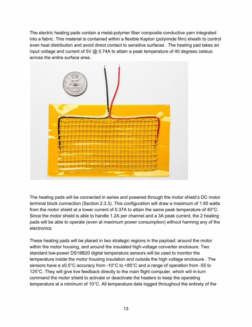
The electric heating pads contain a metalpolymer fiber composite conductive yarn integrated into a fabric. This material is contained within a flexible Kapton (polyimide film) sheath to control even heat distribution and avoid direct contact to sensitive surfaces . The heating pad takes an input voltage and current of 5V @ 0.74A to attain a peak temperature of 40 degrees celsius across the entire surface area.
The heating pads will be connected in series and powered through the motor shield’s DC motor terminal block connection (Section 2.3.3). This configuration will draw a maximum of 1.85 watts from the motor shield at a lower current of 0.37A to attain the same peak temperature of 40°C. Since the motor shield is able to handle 1.2A per channel and a 3A peak current, the 2 heating pads will be able to operate (even at maximum power consumption) without harming any of the electronics. These heating pads will be placed in two strategic regions in the payload: around the motor within the motor housing, and around the insulated highvoltage converter enclosure. Two standard lowpower DS18B20 digital temperature sensors will be used to monitor the temperature inside the motor housing insulation and outside the high voltage enclosure . The sensors have a ±0.5°C accuracy from 10°C to +85°C and a range of operation from 55 to 125°C. They will give live feedback directly to the main flight computer, which will inturn command the motor shield to activate or deactivate the heaters to keep the operating temperature at a minimum of 10°C. All temperature data logged throughout the entirety of the
13

flight will be saved to data logging shield SD memory card (Section 2.3.2). Further testing of the system is outlined in the timeline (Section 4). 3. Team Structure Every aspect of the construction and fabrication of the payload will be run by different student teams all led by Daniel Tikhomirov. Mr. Tikhomirov will be responsible for team management, monthly report submission/teleconferences, and financial/material procurement. Mr. Tikhomirov will oversee the entire engineering aspect of the project and work closely with every team to ensure quality, standards, and safety. There will be no team leads for the project as team leads tend to pull responsibility towards one individual and lead to inefficiency, lack of communication, confusion based on previous experiences. While the team manager will supervise, most of the construction and testing will be done by every member of each team for evenlydistributed work. 12 individuals are to be expected for integrations at CSBF and flight operations ar Ft. Sumner. The construction process is separated into 5 separate teams with students chosen according to skill set, aptitude, and current major. Flight Systems Engineers will be responsible for the main computer and programming it to control and log every aspect of the launch. Thermal Control Engineers will be responsible for insulating the payload and keeping the electronics and moving parts at a controlled temperature. EPC System Engineers will work in the clean room in the fabrication, construction, and testing of the electrostatic particle collector (EPC) assembly. Power Management Engineers are responsible for converting a given voltage from the HASP into the many voltages needed for all the systems in the payload. Mechanical/Structural Engineers will be responsible for installing the motor, constructing the opening mechanism, and constructing the payload frame structure. Teresa Ciardi and Christine Hirst will be the faculty advisors for the project. They will assist in the financial aid, team planning/organization, and providing professional contacts. Professional contacts include the College of the Canyons machine shop with access to advanced machinery including CNC machines and milling machines. Kathy Flynn is the department head for the COC chemistry department and our faculty advisor for clean room operation and protocol. Another important contact is Dr. Don Brownlee from the University of Washington astronomy department. Dr. Brownlee is one of the world’s leading researchers on IDPs and was the principal investigator for NASA’s Stardust mission. His name has been omitted from the contact list due to his informal involvement in the project; Dr. Brownlee mainly contributed in giving information and professional advice. We are currently in talks of having samples flown to the University of Washington for analysis but that has not been confirmed thus far.
Team Manager Daniel Tikhomirov 26455 Rockwell [email protected]
14

Undergraduate Student
Canyon Rd, Santa Clarita, CA 91355
(661) 6003270
Faculty Advisor Teresa Ciardi 26455 Rockwell Canyon Rd, Santa Clarita, CA 91355
Faculty Advisor Christine Hirst 26455 Rockwell Canyon Rd, Santa Clarita, CA 91355
Faculty Advisor Kathy Flynn 26455 Rockwell Canyon Rd, Santa Clarita, CA 91355
Table 1. Affiliations, names, mailing addresses, and contact information 4. Timelines
Month of 2016 Description of Work
January Hardware and funding acquisition. First team meetings and cleanroom setup; high voltage safety briefings
FebruaryMarch Construction and testing of high voltage circuits; Construction of EPC enclosure and motor assembly; Electronics soldering and fabrication
MarchApril Flight computer software development; Stress tests of motor assembly and enclosure; CNC fabrication of payload structure frame parts and construction of payload frame;
April 25 Preliminary PSIP document deadline
AprilMay Testing and integration of flight software; Stress testing of payload frame;
June Final assembly of payload and additional flight testing
June 27 Final PSIP document deadline
July Finalize plan of flight operations; prepare for launch/integration
July 31 Final FLOP document deadline
August 48 Student payload integration
August Flaw corrections and debugging if uncovered
15
September Launch day
October Retrieve payload for shipment back to cleanroom; open EPC enclosure and analyze samples
November Complete sample analysis and final report
December Submit final report
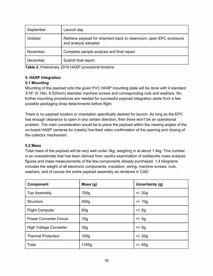
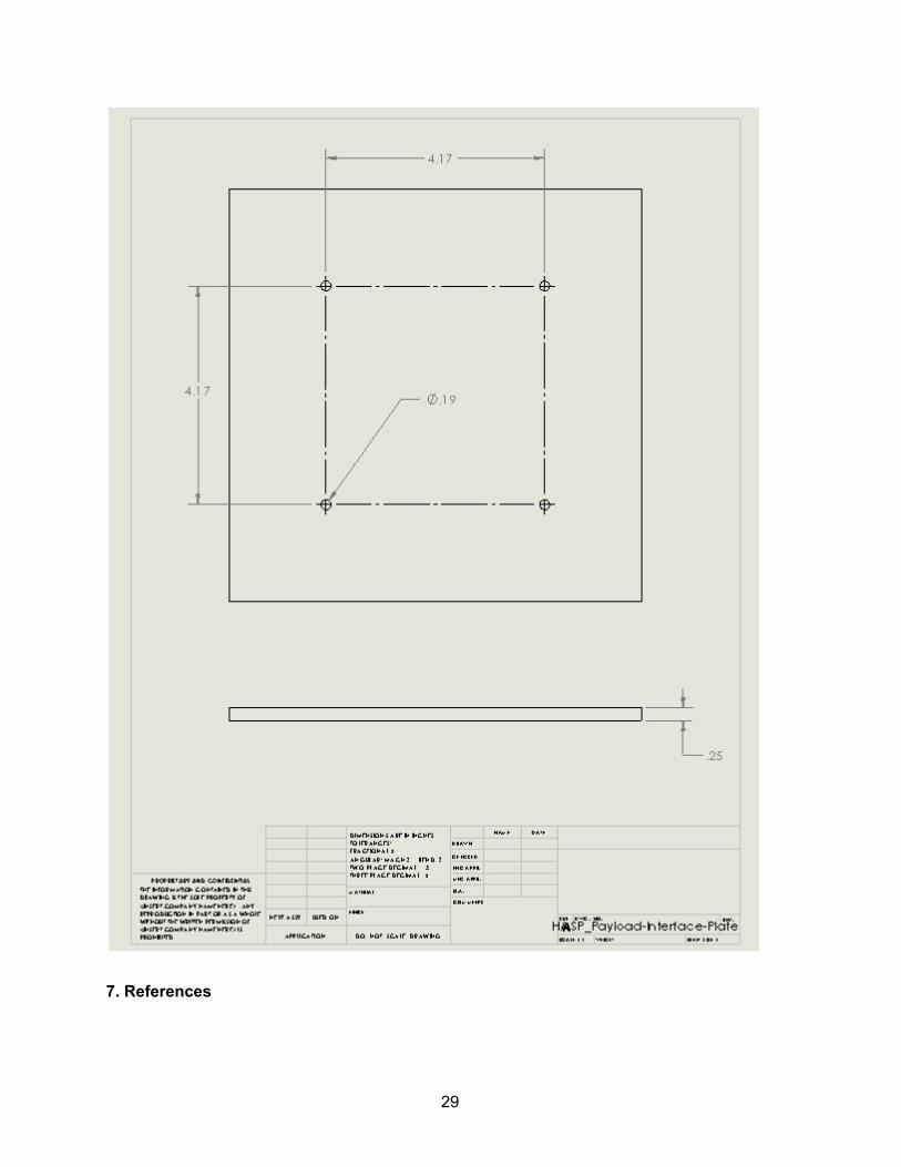
Table 2. Preliminary 2016 HASP procedural timeline 5. HASP Integration 5.1 Mounting Mounting of the payload onto the given PVC HASP mounting plate will be done with 4 standard 3/18” (0.19in, 9.525mm) diameter machine screws and corresponding nuts and washers. No further mounting procedures are needed for successful payload integration aside from a few possible packaging strap detachments before flight. There is no payload location or orientation specifically desired for launch. As long as the EPC has enough clearance to open in any certain direction, then there won’t be an operational problem. The main consideration would be to place the payload within the viewing angles of the onboard HASP cameras for (nearly) livefeed video confirmation of the opening and closing of the collector mechanism. 5.2 Mass Total mass of the payload will be very well under 3kg, weighing in at about 1.4kg. This number is an overestimate that has been derived from careful examination of solidworks mass analysis figures and mass measurements of the few components already purchased. 1.4 kilograms includes the weight of all electronic components, insulation, wiring, machine screws, nuts, washers, and of course the entire payload assembly as rendered in CAD.
Component Mass (g) Uncertainty (g)
Top Assembly 700g +/ 20g
Structure 450g +/ 10g
Flight Computer 60g +/ 5g
Power Converter Circuit 10g +/ 5g
High Voltage Converter 30g +/ 5g
Thermal Protection 100g +/ 20g
Total 1350g +/ 65g
16
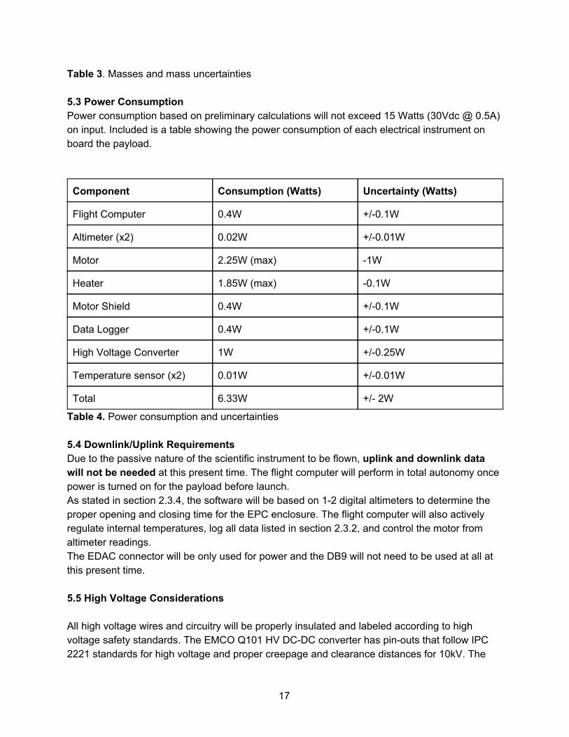
Table 3. Masses and mass uncertainties 5.3 Power Consumption Power consumption based on preliminary calculations will not exceed 15 Watts (30Vdc @ 0.5A) on input. Included is a table showing the power consumption of each electrical instrument on board the payload.
Component Consumption (Watts) Uncertainty (Watts)
Flight Computer 0.4W +/0.1W
Altimeter (x2) 0.02W +/0.01W
Motor 2.25W (max) 1W
Heater 1.85W (max) 0.1W
Motor Shield 0.4W +/0.1W
Data Logger 0.4W +/0.1W
High Voltage Converter 1W +/0.25W
Temperature sensor (x2) 0.01W +/0.01W
Total 6.33W +/ 2W
Table 4. Power consumption and uncertainties 5.4 Downlink/Uplink Requirements Due to the passive nature of the scientific instrument to be flown, uplink and downlink data will not be needed at this present time. The flight computer will perform in total autonomy once power is turned on for the payload before launch. As stated in section 2.3.4, the software will be based on 12 digital altimeters to determine the proper opening and closing time for the EPC enclosure. The flight computer will also actively regulate internal temperatures, log all data listed in section 2.3.2, and control the motor from altimeter readings. The EDAC connector will be only used for power and the DB9 will not need to be used at all at this present time. 5.5 High Voltage Considerations All high voltage wires and circuitry will be properly insulated and labeled according to high voltage safety standards. The EMCO Q101 HV DCDC converter has pinouts that follow IPC 2221 standards for high voltage and proper creepage and clearance distances for 10kV. The
17
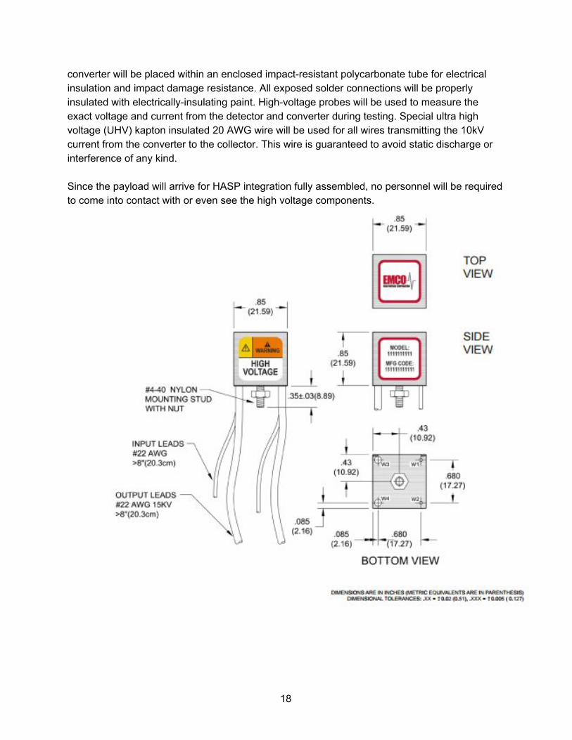
converter will be placed within an enclosed impactresistant polycarbonate tube for electrical insulation and impact damage resistance. All exposed solder connections will be properly insulated with electricallyinsulating paint. Highvoltage probes will be used to measure the exact voltage and current from the detector and converter during testing. Special ultra high voltage (UHV) kapton insulated 20 AWG wire will be used for all wires transmitting the 10kV current from the converter to the collector. This wire is guaranteed to avoid static discharge or interference of any kind. Since the payload will arrive for HASP integration fully assembled, no personnel will be required to come into contact with or even see the high voltage components.
18
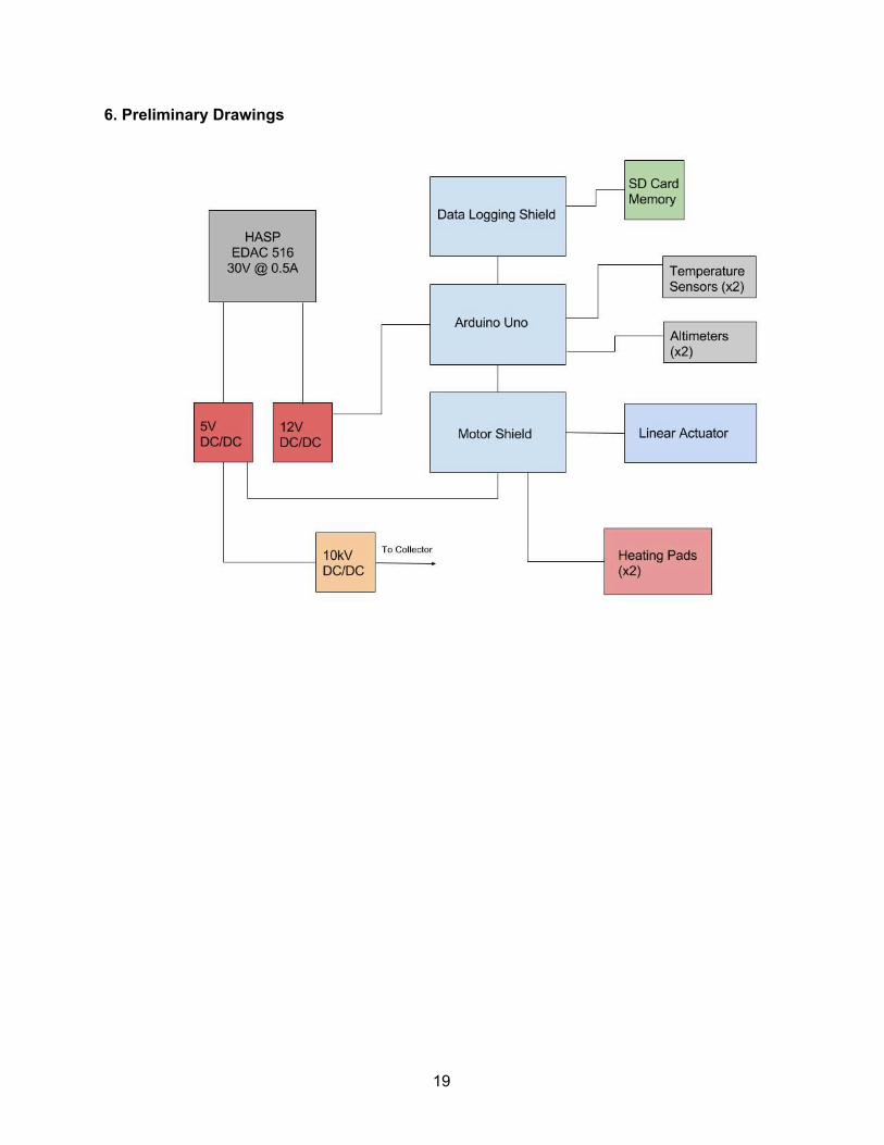
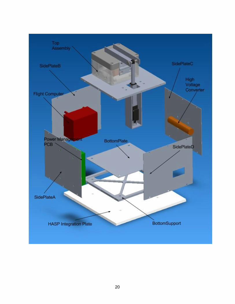
6. Preliminary Drawings
19
20
21
22
23
24
25
26
27
28
7. References
29

"Cosmic Dust Webpage." Cosmic Dust from the Stratosphere. Learning & Scholarly Technologies, 1998. Web. 7 Oct. 2015. <https://catalyst.uw.edu/workspace/idp/40208/285085>. "Cosmic Dust Webpage Astrobiology." Astrobiology. Learning & Scholarly Technologies, 1998. Web. 7 Oct. 2015. <https://catalyst.uw.edu/workspace/idp/40208/285083>.
30


![Hydrogen-Alpha Exploration with Light Intensity Observation Systems (HELIOS) II Final ...laspace.lsu.edu/hasp/groups/2013/science_report/Payload... · 2013-12-15 · [Type text] 1](https://img.pdfslide.us/doc/110x75/5f54aae2cedc2273804cda0f/hydrogen-alpha-exploration-with-light-intensity-observation-systems-helios-ii.jpg)