Embed Size (px)
Citation preview
EIO
0000
0006
14.1
1
www.se.com
Harmony HMISTU655/855
EIO0000000614
Harmony HMISTU655/855User Manual01/2022

2 EIO0000000614
The information provided in this documentation contains general descriptions and/or technical characteristics of the performance of the products contained herein. This documentation is not intended as a substitute for and is not to be used for determining suitability or reliability of these products for specific user applications. It is the duty of any such user or integrator to perform the appropriate and complete risk analysis, evaluation and testing of the products with respect to the relevant specific application or use thereof. Neither Schneider Electric nor any of its affiliates or subsidiaries shall be responsible or liable for misuse of the information contained herein. If you have any suggestions for improvements or amendments or have found errors in this publication, please notify us. You agree not to reproduce, other than for your own personal, noncommercial use, all or part of this document on any medium whatsoever without permission of Schneider Electric, given in writing. You also agree not to establish any hypertext links to this document or its content. Schneider Electric does not grant any right or license for the personal and noncommercial use of the document or its content, except for a non-exclusive license to consult it on an "as is" basis, at your own risk. All other rights are reserved.All pertinent state, regional, and local safety regulations must be observed when installing and using this product. For reasons of safety and to help ensure compliance with documented system data, only the manufacturer should perform repairs to components.When devices are used for applications with technical safety requirements, the relevant instructions must be followed. Failure to use Schneider Electric software or approved software with our hardware products may result in injury, harm, or improper operating results.Failure to observe this information can result in injury or equipment damage.© 2022 Schneider Electric. All rights reserved.
Table of Contents
Safety Information. . . . . . . . . . . . . . . . . . . . . . . . . . . . . . 5About the Book . . . . . . . . . . . . . . . . . . . . . . . . . . . . . . . . 7
Part I HMISTU655/855 Panels . . . . . . . . . . . . . . . . . . . . . . 9Chapter 1 HMISTU655/855 Panels . . . . . . . . . . . . . . . . . . . . . . . . . 11
HMISTU655/855 Series of Panels. . . . . . . . . . . . . . . . . . . . . . . . . . . . 12HMISTU655/855 Package Contents . . . . . . . . . . . . . . . . . . . . . . . . . . 15Accessories . . . . . . . . . . . . . . . . . . . . . . . . . . . . . . . . . . . . . . . . . . . . . 16Parts Identification and Functions . . . . . . . . . . . . . . . . . . . . . . . . . . . . 20Certifications and Standards . . . . . . . . . . . . . . . . . . . . . . . . . . . . . . . . 24System Design . . . . . . . . . . . . . . . . . . . . . . . . . . . . . . . . . . . . . . . . . . 26
Chapter 2 Specifications . . . . . . . . . . . . . . . . . . . . . . . . . . . . . . . . . 292.1 General Specifications. . . . . . . . . . . . . . . . . . . . . . . . . . . . . . . . . . . . . 30
General Specifications. . . . . . . . . . . . . . . . . . . . . . . . . . . . . . . . . . . . . 302.2 Functional Specifications. . . . . . . . . . . . . . . . . . . . . . . . . . . . . . . . . . . 32
Display. . . . . . . . . . . . . . . . . . . . . . . . . . . . . . . . . . . . . . . . . . . . . . . . . 33Memory, Clock, and Touch Panel . . . . . . . . . . . . . . . . . . . . . . . . . . . . 35
2.3 Interface Specifications . . . . . . . . . . . . . . . . . . . . . . . . . . . . . . . . . . . . 36Interface Specifications . . . . . . . . . . . . . . . . . . . . . . . . . . . . . . . . . . . . 37Specifications of Serial Interface COM1 . . . . . . . . . . . . . . . . . . . . . . . 38
2.4 Dimensions . . . . . . . . . . . . . . . . . . . . . . . . . . . . . . . . . . . . . . . . . . . . . 40HMISTU655/855 . . . . . . . . . . . . . . . . . . . . . . . . . . . . . . . . . . . . . . . . . 40
Chapter 3 Installation and Wiring . . . . . . . . . . . . . . . . . . . . . . . . . . 453.1 Installation . . . . . . . . . . . . . . . . . . . . . . . . . . . . . . . . . . . . . . . . . . . . . . 46
Panel Cut-out Dimensions and Installation . . . . . . . . . . . . . . . . . . . . . 47Installation Procedures . . . . . . . . . . . . . . . . . . . . . . . . . . . . . . . . . . . . 51
3.2 Wiring Principles . . . . . . . . . . . . . . . . . . . . . . . . . . . . . . . . . . . . . . . . . 57Connecting the Power Cord . . . . . . . . . . . . . . . . . . . . . . . . . . . . . . . . 58Connecting the Power Supply . . . . . . . . . . . . . . . . . . . . . . . . . . . . . . . 61Grounding . . . . . . . . . . . . . . . . . . . . . . . . . . . . . . . . . . . . . . . . . . . . . . 63
3.3 USB Port . . . . . . . . . . . . . . . . . . . . . . . . . . . . . . . . . . . . . . . . . . . . . . . 65Important Considerations When Using the USB Port . . . . . . . . . . . . . 66USB Data Transfer Cable (BMXXCAUSBH018) - USB Driver Installation . . . . . . . . . . . . . . . . . . . . . . . . . . . . . . . . . . . . . . . . . . . . . . 67USB Standard A . . . . . . . . . . . . . . . . . . . . . . . . . . . . . . . . . . . . . . . . . 69USB Mini-B . . . . . . . . . . . . . . . . . . . . . . . . . . . . . . . . . . . . . . . . . . . . . 74
EIO0000000614 3
3.4 Ethernet Cable Connector . . . . . . . . . . . . . . . . . . . . . . . . . . . . . . . . . . 77Presentation . . . . . . . . . . . . . . . . . . . . . . . . . . . . . . . . . . . . . . . . . . . . . 77
Part II Settings . . . . . . . . . . . . . . . . . . . . . . . . . . . . . . . . . . 79Chapter 4 Configuring the Unit . . . . . . . . . . . . . . . . . . . . . . . . . . . . . 81
Types of Settings . . . . . . . . . . . . . . . . . . . . . . . . . . . . . . . . . . . . . . . . . 82System Settings . . . . . . . . . . . . . . . . . . . . . . . . . . . . . . . . . . . . . . . . . . 83Offline Settings. . . . . . . . . . . . . . . . . . . . . . . . . . . . . . . . . . . . . . . . . . . 87Diagnostics Settings. . . . . . . . . . . . . . . . . . . . . . . . . . . . . . . . . . . . . . . 90
Chapter 5 Troubleshooting . . . . . . . . . . . . . . . . . . . . . . . . . . . . . . . . 93Troubleshooting Checklists . . . . . . . . . . . . . . . . . . . . . . . . . . . . . . . . . 94Self Test List . . . . . . . . . . . . . . . . . . . . . . . . . . . . . . . . . . . . . . . . . . . . 97
Chapter 6 Maintenance. . . . . . . . . . . . . . . . . . . . . . . . . . . . . . . . . . . 99Regular Cleaning . . . . . . . . . . . . . . . . . . . . . . . . . . . . . . . . . . . . . . . . . 100Periodic Check Points . . . . . . . . . . . . . . . . . . . . . . . . . . . . . . . . . . . . . 102
Index . . . . . . . . . . . . . . . . . . . . . . . . . . . . . . . . . . . . . . . . . 103
4 EIO0000000614
Safety Information
Important Information
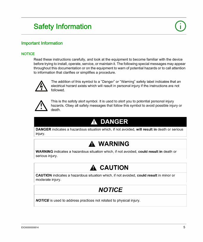
NOTICERead these instructions carefully, and look at the equipment to become familiar with the device before trying to install, operate, service, or maintain it. The following special messages may appear throughout this documentation or on the equipment to warn of potential hazards or to call attention to information that clarifies or simplifies a procedure.
EIO0000000614 5
PLEASE NOTEElectrical equipment should be installed, operated, serviced, and maintained only by qualified personnel. No responsibility is assumed by Schneider Electric for any consequences arising out of the use of this material.A qualified person is one who has skills and knowledge related to the construction and operation of electrical equipment and its installation, and has received safety training to recognize and avoid the hazards involved.
6 EIO0000000614
About the Book
At a Glance
Document ScopeThis manual describes how to use the Harmony HMISTU655/855 and HMISTU655W/855W units.The HMISTU655W/855W series are same as the standard STU series, only without marking on the front overlay (no Schneider logo or Harmony printed on the front).In rest of the document, HMISTU655/855 references apply for both series (regular and W) unless otherwise specified.All overlay drawings in this document are of HMISTU655/855 series.
Validity NoteThis documentation is valid for the HMISTU655/855 and HMISTU655W/855W when used with Vijeo Designer version 6.1 SP2 or later.
Product Related Information
WARNINGUNINTENDED EQUIPMENT OPERATION The application of this product requires expertise in the design and programming of control systems. Only persons with such expertise should be allowed to program, install, alter, and apply this product.Follow all local and national safety codes and standards.Failure to follow these instructions can result in death, serious injury, or equipment damage.
EIO0000000614 7
Cybersecurity Best PracticesTo help keep your Schneider Electric products secure and protected, we recommend that you implement the cybersecurity best practices. Following the recommendations may help significantly reduce cybersecurity risk of your company. For the recommendations, refer to the following URL:https://www.se.com/en/download/document/7EN52-0390/
WARNINGPOTENTIAL COMPROMISE OF SYSTEM AVAILABILITY, INTEGRITY, AND CONFIDENTIALITY Change default passwords. Disable unused ports/services and default accounts, wherever possible. Place networked devices behind multiple layers of cyber defenses (such as firewalls, network
segmentation, and network intrusion detection and protection). Use cyber security best practices (for example: least privilege, separation of duties).Failure to follow these instructions can result in death, serious injury, or equipment damage.
8 EIO0000000614
Harmony HMISTU655/855HMISTU655/855EIO0000000614
HMISTU655/855 Panels
Part IHMISTU655/855 Panels
OverviewThis part describes how to use HMISTU655/855 Panels.
What Is in This Part?This part contains the following chapters:
Chapter Chapter Name Page1 HMISTU655/855 Panels 112 Specifications 293 Installation and Wiring 45
EIO0000000614 9

HMISTU655/855
10 EIO0000000614
Harmony HMISTU655/855HMISTU655/855EIO0000000614
HMISTU655/855 Panels
Chapter 1HMISTU655/855 Panels
OverviewThis chapter describes the HMISTU655/855 Panels and connectable devices.
What Is in This Chapter?This chapter contains the following topics:
Topic PageHMISTU655/855 Series of Panels 12HMISTU655/855 Package Contents 15Accessories 16Parts Identification and Functions 20Certifications and Standards 24System Design 26
EIO0000000614 11
HMISTU655/855
HMISTU655/855 Series of Panels
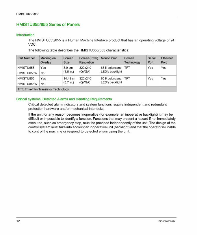
IntroductionThe HMISTU655/855 is a Human Machine Interface product that has an operating voltage of 24 VDC.The following table describes the HMISTU655/855 characteristics:
Critical systems, Detected Alarms and Handling RequirementsCritical detected alarm indicators and system functions require independent and redundant protection hardware and/or mechanical interlocks.If the unit for any reason becomes inoperative (for example, an inoperative backlight) it may be difficult or impossible to identify a function. Functions that may present a hazard if not immediately executed, such as emergency stop, must be provided independently of the unit. The design of the control system must take into account an inoperative unit (backlight) and that the operator is unable to control the machine or respond to detected errors using the unit.
Part Number Marking on Overlay
Screen Size
Screen (Pixel) Resolution
Mono/Color Screen Technology
Serial Port
Ethernet Port
HMISTU655 Yes 8.9 cm (3.5 in.)
320x240(QVGA)
65 K colors and LED's backlight
TFT Yes YesHMISTU655W NoHMISTU855 Yes 14.48 cm
(5.7 in.)320x240(QVGA)
65 K colors and LED's backlight
TFT Yes YesHMISTU855W NoTFT: Thin-Film Transistor Technology.
12 EIO0000000614
HMISTU655/855
When the power is cycled, wait at least 10 seconds before restoring the power to the HMI unit. Switching the power OFF and ON quickly can damage the unit.
WARNINGLOSS OF CONTROL Consider the potential failure modes of control paths in the machine control system design,
such as: The possibility of backlight failure, Unanticipated link transmission delays or failures, The operator being unable to control the machine, The operator making errors in the control of the machine.
Provide a means to achieve a safe state during and after a path failure for critical control functions such as emergency stop and overtravel stop.
Provide separate or redundant control paths for critical control functions. Test individually and thorougly each implementation of the HMISTU655/855 for correct
operation before service.Failure to follow these instructions can result in death, serious injury, or equipment damage.
WARNINGUNINTENDED EQUIPMENT OPERATION Do not use the unit as the only means of control for critical system functions such as motor
start/stop or power control. Do not use the unit as the only notification device for critical alarms, such as device
overheating or overcurrent.Failure to follow these instructions can result in death, serious injury, or equipment damage.
EIO0000000614 13
HMISTU655/855
Handling the LCD PanelThe following characteristics are specific to the LCD unit and are considered normal behavior: LCD screen may show unevenness in the brightness of certain images or may appear different
when seen from outside the specified viewing angle. Extended shadows, or cross-talk, may also appear on the sides of screen images.
LCD screen pixels may contain black and white colored spots and color display may seem to have changed over time.
When the same image is displayed on the screen for a long period, an after-image may appear when the image is changed. If this happens, turn off the unit, wait 10 seconds and then restart it.
NOTE: Do not display the same image for a long time, change the screen image periodically.
Using Touch Panel Correctly
Use only one finger to select an object on the touch panel.If the touch panel receives pressure at two or more points at the same time, an unintended object could be selected.
CAUTIONSERIOUS EYE AND SKIN INJURYThe liquid present in the LCD panel contains an irritant: Avoid direct skin contact with the liquid. Wear gloves when you handle a broken or leaking unit. Do not use sharp objects or tools in the vicinity of the LCD touch panel. Handle the LCD panel carefully to prevent puncture, bursting, or cracking of the panel material.If the panel is damaged and any liquid comes in contact with your skin, immediately rinse the area with running water for at least 15 min.If the liquid gets in your eyes, immediately rinse your eyes with running water for at least 15 minutes and consult a doctor.Failure to follow these instructions can result in injury or equipment damage.
WARNINGUNINTENDED EQUIPMENT OPERATION Operate the HMISTU655/855 touch panel with only one finger. Do not activate two or more points of the touch panel simultaneously.Failure to follow these instructions can result in death, serious injury, or equipment damage.
14 EIO0000000614
HMISTU655/855
HMISTU655/855 Package Contents
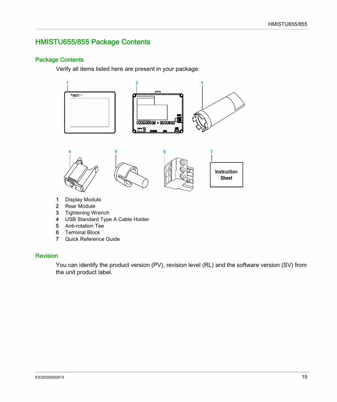
Package ContentsVerify all items listed here are present in your package:
1 Display Module2 Rear Module3 Tightening Wrench4 USB Standard Type A Cable Holder5 Anti-rotation Tee6 Terminal Block7 Quick Reference Guide
RevisionYou can identify the product version (PV), revision level (RL) and the software version (SV) from the unit product label.
EIO0000000614 15
HMISTU655/855
Accessories
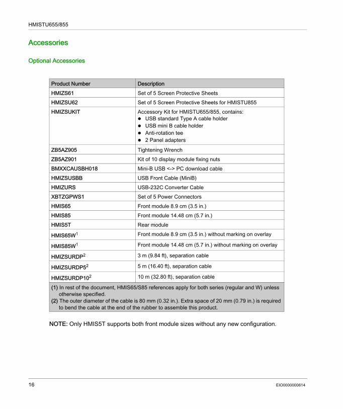
Optional Accessories
NOTE: Only HMIS5T supports both front module sizes without any new configuration.
Product Number DescriptionHMIZS61 Set of 5 Screen Protective SheetsHMIZSU62 Set of 5 Screen Protective Sheets for HMISTU855HMIZSUKIT Accessory Kit for HMISTU655/855, contains:
USB standard Type A cable holder USB mini B cable holder Anti-rotation tee 2 Panel adapters
ZB5AZ905 Tightening WrenchZB5AZ901 Kit of 10 display module fixing nutsBMXXCAUSBH018 Mini-B USB <-> PC download cableHMIZSUSBB USB Front Cable (MiniB)HMIZURS USB-232C Converter CableXBTZGPWS1 Set of 5 Power ConnectorsHMIS65 Front module 8.9 cm (3.5 in.)HMIS85 Front module 14.48 cm (5.7 in.)HMIS5T Rear module
HMIS65W1 Front module 8.9 cm (3.5 in.) without marking on overlay
HMIS85W1 Front module 14.48 cm (5.7 in.) without marking on overlay
HMIZSURDP2 3 m (9.84 ft), separation cable
HMIZSURDP52 5 m (16.40 ft), separation cable
HMIZSURDP102 10 m (32.80 ft), separation cable
(1) In rest of the document, HMIS65/S85 references apply for both series (regular and W) unless otherwise specified.
(2) The outer diameter of the cable is 80 mm (0.32 in.). Extra space of 20 mm (0.79 in.) is required to bend the cable at the end of the rubber to assemble this product.
16 EIO0000000614
HMISTU655/855
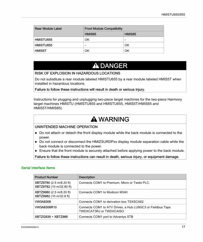
Instructions for plugging and unplugging two-piece target machines for the two-piece Harmony target machines HMISTU (HMISTU855 and HMISTU655, HMIS5T/HMIS65 and HMIS5T/HMIS85).
Serial Interface Items
Rear Module Label Front Module CompatibilityHMIS65 HMIS85
HMISTU655 OK –HMISTU855 – OKHMIS5T OK OK
DANGERRISK OF EXPLOSION IN HAZARDOUS LOCATIONSDo not substitute a rear module labeled HMISTU655 by a rear module labeled HMIS5T when installed in hazardous locations.Failure to follow these instructions will result in death or serious injury.
WARNINGUNINTENDED MACHINE OPERATION Do not attach or detach the front display module while the back module is connected to the
power. Do not connect or disconnect the HMIZSURDPxx display module separation cable while the
back module is connected to the power. Ensure that the front module is securely attached before applying power to the back module.Failure to follow these instructions can result in death, serious injury, or equipment damage.
Product Number DescriptionXBTZ9780 (2.5 m/8.20 ft)XBTZ9782 (10 m/32.80 ft)
Connects COM1 to Premium, Micro or Twido PLC.
XBTZ9980 (2.5 m/8.20 ft)XBTZ9982 (10 m/32.8 ft)
Connects COM1 to Modicon M340
VW3A8306 Connects COM1 to derivation box TSXSCA62VW3A8306R10 Connects COM1 to ATV Drives, a Hub LU9GC3 or Fieldbus Taps
TWDXCAT3RJ or TWDXCAISOXBTZG939 + XBTZ988 Connects COM1 port to Advantys STB
EIO0000000614 17
HMISTU655/855
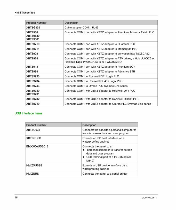
USB Interface Items
XBTZG939 Cable adapter COM1, RJ45XBTZ968 XBTZ9680 XBTZ9681
Connects COM1 port with XBTZ adapter to Premium, Micro or Twido PLC
XBTZ9710 Connects COM1 port with XBTZ adapter to Quantum PLCXBTZ9711 Connects COM1 port with XBTZ adapter to Momentum PLCXBTZ908 Connects COM1 port with XBTZ adapter to derivation box TSXSCA62XBTZ938 Connects COM1 port with XBTZ adapter to ATV drives, a Hub LU9GC3 or
Fieldbus Taps TWDXCAT3RJ or TWDXCAISOXBTZ918 Connects COM1 port with XBTZ adapter to Premium SCYXBTZ988 Connects COM1 port with XBTZ adapter to Advantys STBXBTZ9733 Connects COM1 to Rockwell DF1 Logix PLCXBTZ9734 Connects COM1 to Rockwell DH485 Logix PLCXBTZ9743 Connects COM1 to Omron PLC Sysmac Link seriesXBTZ9730XBTZ9731
Connects COM1 with XBTZ adapter to Rockwell DF1 PLC
XBTZ9732 Connects COM1 with XBTZ adapter to Rockwell DH485 PLCXBTZ9740 Connects COM1 with XBTZ adapter to Omron PLC Sysmac Link series
Product Number Description
Product Number DescriptionXBTZG935 Connects the panel to a personal computer to
transfer screen data and user programXBTZGUSB Extends a USB host interface on a
waterproofing cabinetBMXXCAUSB018 Connects the panel to a:
personal computer to transfer screen data and user program
USB terminal port of a PLC (Modicon M340)
HMIZSUSBB Extends a USB device interface on a waterproofing cabinet
HMIZURS Connects the panel to a serial printer
18 EIO0000000614
HMISTU655/855
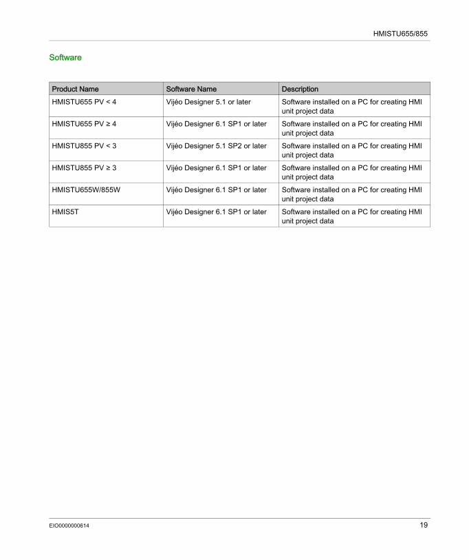
Software
Product Name Software Name DescriptionHMISTU655 PV < 4 Vijéo Designer 5.1 or later Software installed on a PC for creating HMI
unit project dataHMISTU655 PV ≥ 4 Vijéo Designer 6.1 SP1 or later Software installed on a PC for creating HMI
unit project dataHMISTU855 PV < 3 Vijéo Designer 5.1 SP2 or later Software installed on a PC for creating HMI
unit project dataHMISTU855 PV ≥ 3 Vijéo Designer 6.1 SP1 or later Software installed on a PC for creating HMI
unit project dataHMISTU655W/855W Vijéo Designer 6.1 SP1 or later Software installed on a PC for creating HMI
unit project dataHMIS5T Vijéo Designer 6.1 SP1 or later Software installed on a PC for creating HMI
unit project data
EIO0000000614 19
HMISTU655/855
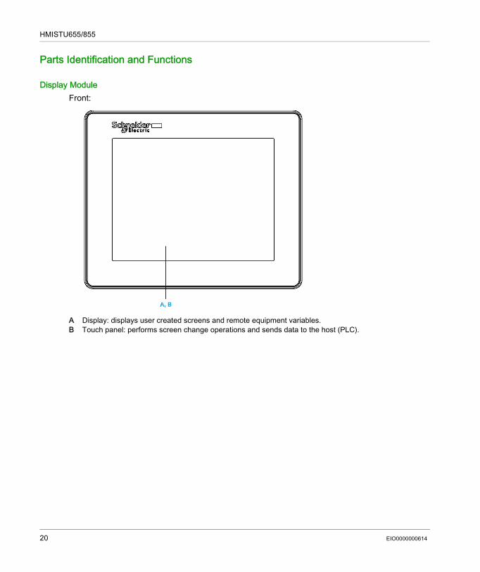
Parts Identification and Functions
Display ModuleFront:
A Display: displays user created screens and remote equipment variables.B Touch panel: performs screen change operations and sends data to the host (PLC).
20 EIO0000000614
HMISTU655/855
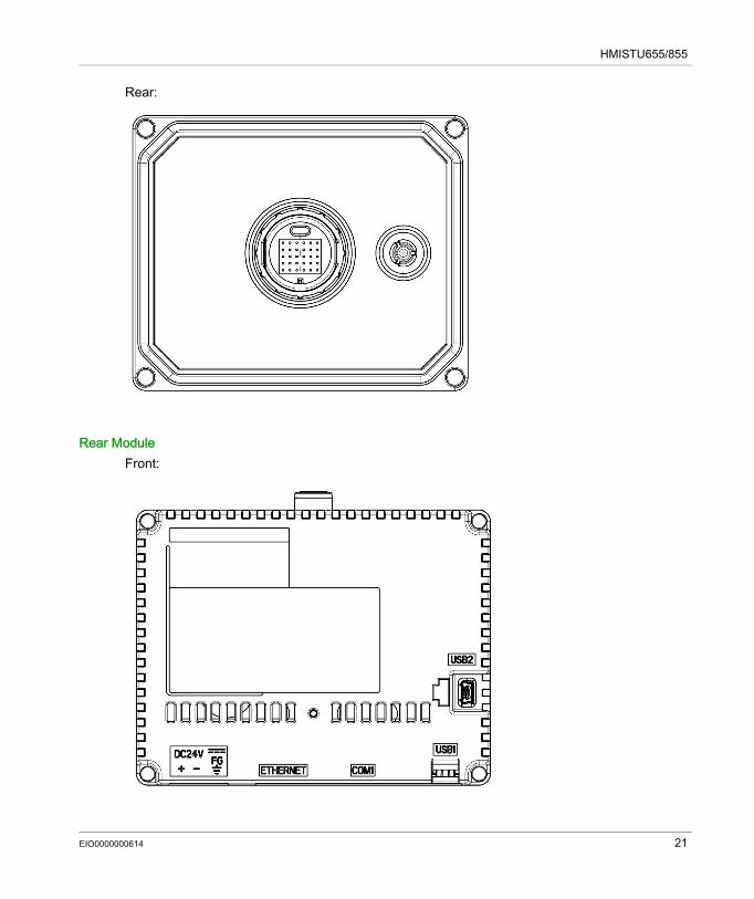
Rear:
Rear ModuleFront:
EIO0000000614 21
HMISTU655/855
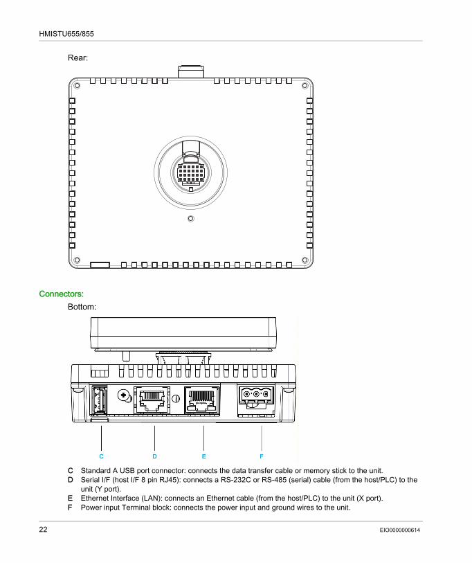
Rear:
Connectors:Bottom:
C Standard A USB port connector: connects the data transfer cable or memory stick to the unit.D Serial I/F (host I/F 8 pin RJ45): connects a RS-232C or RS-485 (serial) cable (from the host/PLC) to the
unit (Y port). E Ethernet Interface (LAN): connects an Ethernet cable (from the host/PLC) to the unit (X port).F Power input Terminal block: connects the power input and ground wires to the unit.
22 EIO0000000614
HMISTU655/855
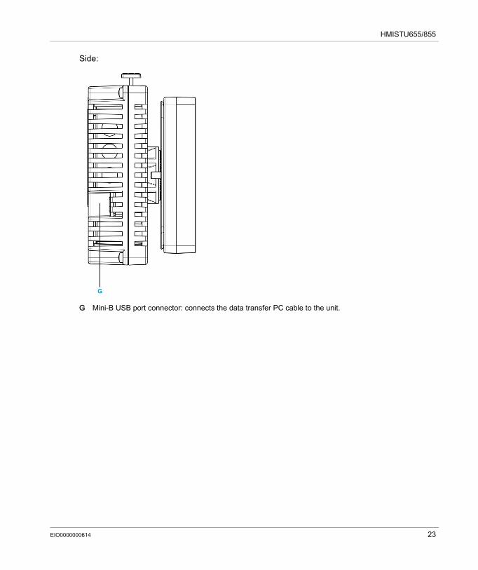
Side:
G Mini-B USB port connector: connects the data transfer PC cable to the unit.
EIO0000000614 23
HMISTU655/855
Certifications and Standards
IntroductionSchneider Electric submitted this product for independent testing and qualification by third-party listing agencies. These agencies have certified this product as meeting the following standards.
Agency Certifications for HMISTU655/855 UnitHMISTU655/855 unit is certified by the Underwriters Laboratory according to: UL 508 and CSA C22.2 n°142 for Industrial Control Equipment ANSI/ISA 12.12.01 and CSA C22.2 n°213 for Electrical Equipment for Use in Class I, Division
2 Hazardous LocationsATEX certification by INERIS is ongoing, please refer to product label.HMISTU655/855 unit is designed to comply to merchant navy bridge and deck requirements (Refer to the Schneider Electric website for installation guidelines).For detailed information, contact your local distributor or see the catalog & marking on the product.
Hazardous SubstancesHMISTU655/855 unit is designed for compliance with: WEEE, Directive 2002/96/EC RoHS, Directive 2011/65/EU RoHS China, Standard SJ/T 11363-2006
UL Conditions of Acceptability and Handling Cautions for HMISTU655/855 UnitThe HMISTU655/855 unit is suitable for use in hazardous locations in accordance with Class 1, Division 2 standards. All relevant local, state, and regional codes must be followed.
24 EIO0000000614
HMISTU655/855
CE MarkingsThis product conforms to the necessary requirements of the following Directives for applying the CE label: 2006/95/EC Low Voltage Directive 2004/108/EC EMC DirectiveThis conformity is based on compliance with IEC61131-2.
Interfaces are: COM1, ETHERNET, USB1 and USB2.
WARNINGRISK OF EXPLOSION IN HAZARDOUS LOCATIONS Verify that the power, input and output (I/O) wiring are in accordance with Class I, Division 2
wiring methods. Do not substitute components that may impair compliance to Class I, Division 2. Do not connect or disconnect equipment unless power has been switched off or the area is
known to be non-hazardous. Securely lock externally connected units and each interface before turning on the power
supply.Failure to follow these instructions can result in death, serious injury, or equipment damage.
WARNINGRISK OF EXPLOSION IN HAZARDOUS LOCATIONS Do not disconnect while circuit is live. Potential electrostatic charging hazard: wipe the front panel of the terminal with a damp cloth
before turning ON.Failure to follow these instructions can result in death, serious injury, or equipment damage.
EIO0000000614 25
HMISTU655/855
System Design
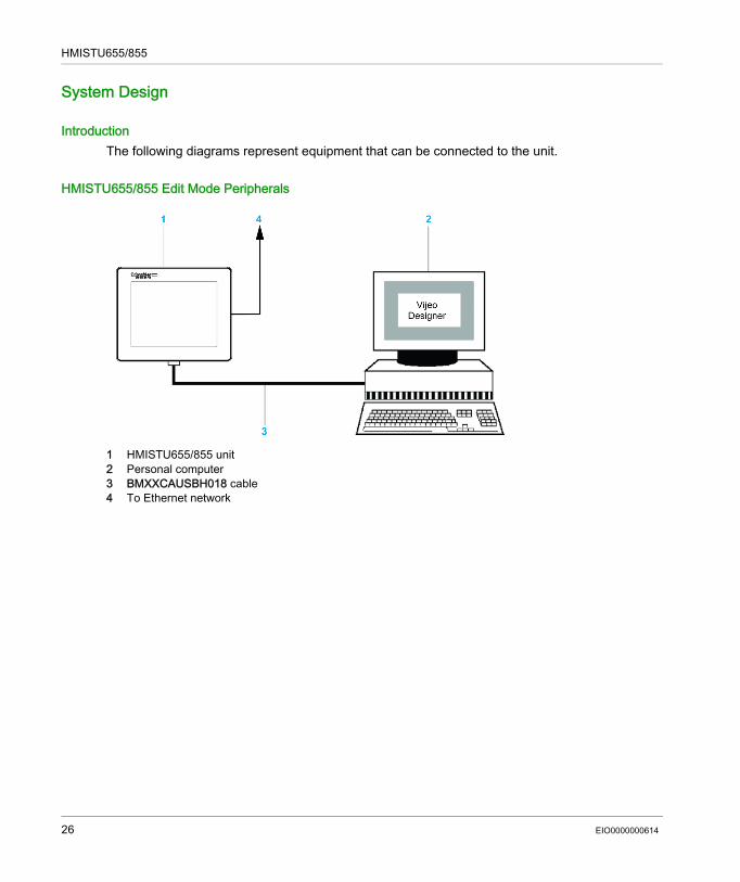
IntroductionThe following diagrams represent equipment that can be connected to the unit.
HMISTU655/855 Edit Mode Peripherals
1 HMISTU655/855 unit2 Personal computer3 BMXXCAUSBH018 cable4 To Ethernet network
26 EIO0000000614
HMISTU655/855
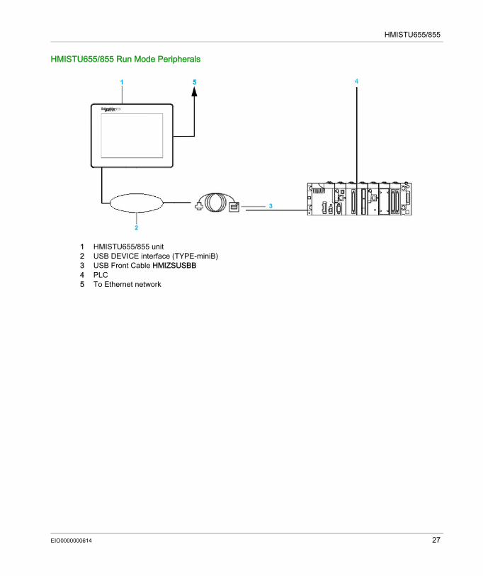
HMISTU655/855 Run Mode Peripherals
1 HMISTU655/855 unit 2 USB DEVICE interface (TYPE-miniB)3 USB Front Cable HMIZSUSBB4 PLC5 To Ethernet network
EIO0000000614 27
HMISTU655/855
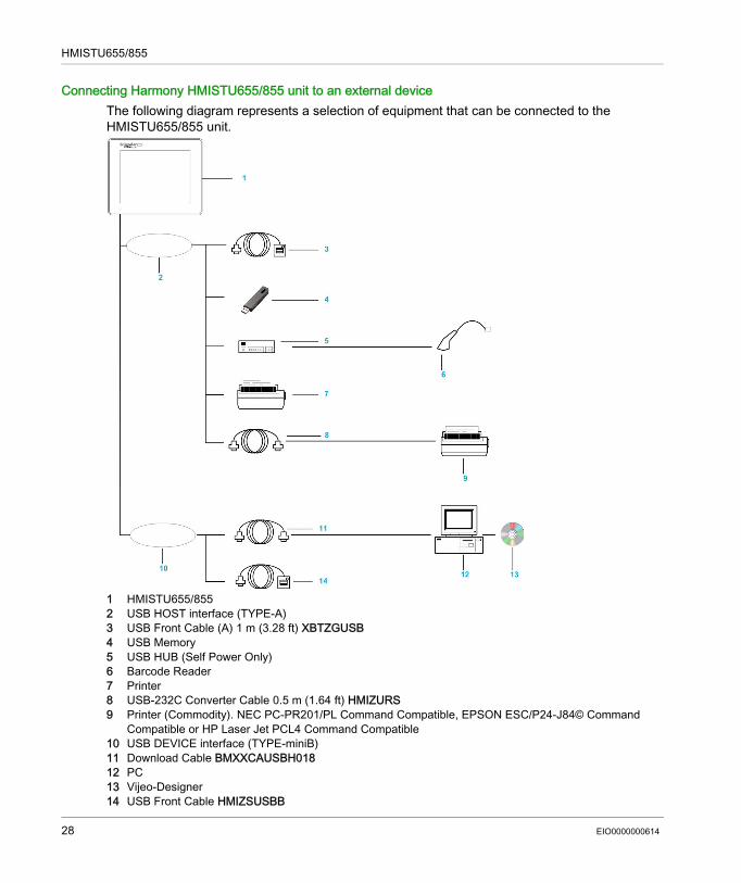
Connecting Harmony HMISTU655/855 unit to an external deviceThe following diagram represents a selection of equipment that can be connected to the HMISTU655/855 unit.
1 HMISTU655/8552 USB HOST interface (TYPE-A)3 USB Front Cable (A) 1 m (3.28 ft) XBTZGUSB4 USB Memory5 USB HUB (Self Power Only)6 Barcode Reader7 Printer8 USB-232C Converter Cable 0.5 m (1.64 ft) HMIZURS9 Printer (Commodity). NEC PC-PR201/PL Command Compatible, EPSON ESC/P24-J84© Command
Compatible or HP Laser Jet PCL4 Command Compatible10 USB DEVICE interface (TYPE-miniB)11 Download Cable BMXXCAUSBH01812 PC13 Vijeo-Designer14 USB Front Cable HMIZSUSBB
28 EIO0000000614
Harmony HMISTU655/855
EIO0000000614
Specifications
Chapter 2Specifications
OverviewThis chapter presents the HMISTU655/855 specifications.
What Is in This Chapter?This chapter contains the following sections:
Section Topic Page2.1 General Specifications 302.2 Functional Specifications 322.3 Interface Specifications 362.4 Dimensions 40
EIO0000000614 29
General Specifications
Section 2.1General Specifications
General Specifications
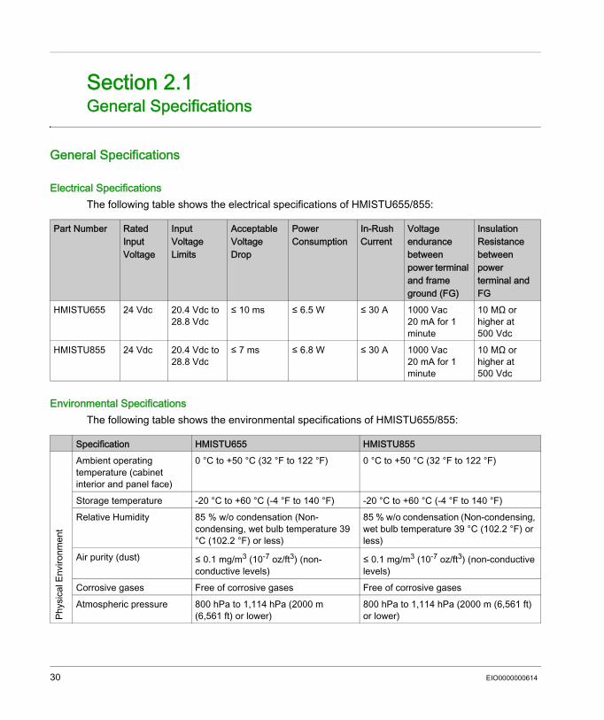
Electrical SpecificationsThe following table shows the electrical specifications of HMISTU655/855:
Environmental SpecificationsThe following table shows the environmental specifications of HMISTU655/855:
Part Number Rated Input Voltage
Input Voltage Limits
Acceptable Voltage Drop
Power Consumption
In-Rush Current
Voltage endurance between power terminal and frame ground (FG)
Insulation Resistance between power terminal and FG
HMISTU655 24 Vdc 20.4 Vdc to 28.8 Vdc
≤ 10 ms ≤ 6.5 W ≤ 30 A 1000 Vac 20 mA for 1 minute
10 MΩ or higher at 500 Vdc
HMISTU855 24 Vdc 20.4 Vdc to 28.8 Vdc
≤ 7 ms ≤ 6.8 W ≤ 30 A 1000 Vac 20 mA for 1 minute
10 MΩ or higher at 500 Vdc
Specification HMISTU655 HMISTU855
Phys
ical
Env
ironm
ent
Ambient operating temperature (cabinet interior and panel face)
0 °C to +50 °C (32 °F to 122 °F) 0 °C to +50 °C (32 °F to 122 °F)
Storage temperature -20 °C to +60 °C (-4 °F to 140 °F) -20 °C to +60 °C (-4 °F to 140 °F)Relative Humidity 85 % w/o condensation (Non-
condensing, wet bulb temperature 39 °C (102.2 °F) or less)
85 % w/o condensation (Non-condensing, wet bulb temperature 39 °C (102.2 °F) or less)
Air purity (dust) ≤ 0.1 mg/m3 (10-7 oz/ft3) (non-conductive levels)
≤ 0.1 mg/m3 (10-7 oz/ft3) (non-conductive levels)
Corrosive gases Free of corrosive gases Free of corrosive gasesAtmospheric pressure 800 hPa to 1,114 hPa (2000 m
(6,561 ft) or lower)800 hPa to 1,114 hPa (2000 m (6,561 ft) or lower)
30 EIO0000000614
Mec
hani
cal E
nviro
nmen
t
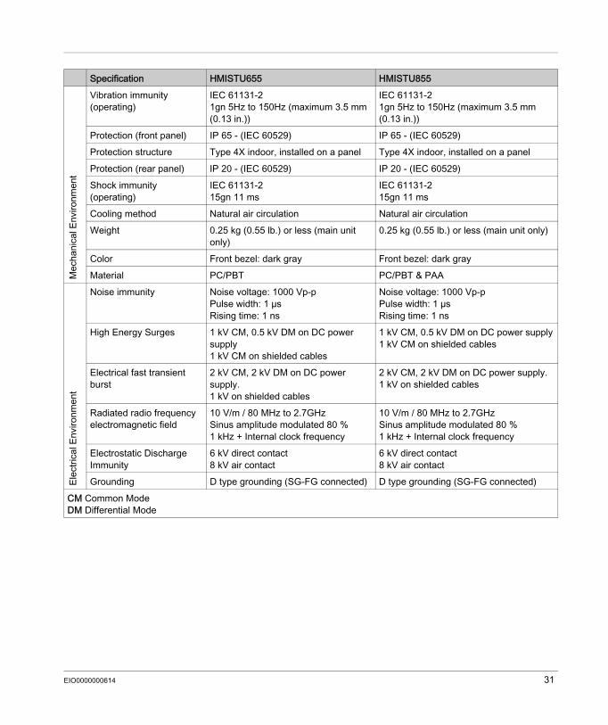
Vibration immunity (operating)
IEC 61131-21gn 5Hz to 150Hz (maximum 3.5 mm (0.13 in.))
IEC 61131-21gn 5Hz to 150Hz (maximum 3.5 mm (0.13 in.))
Protection (front panel) IP 65 - (IEC 60529) IP 65 - (IEC 60529)Protection structure Type 4X indoor, installed on a panel Type 4X indoor, installed on a panelProtection (rear panel) IP 20 - (IEC 60529) IP 20 - (IEC 60529) Shock immunity (operating)
IEC 61131-215gn 11 ms
IEC 61131-215gn 11 ms
Cooling method Natural air circulation Natural air circulationWeight 0.25 kg (0.55 lb.) or less (main unit
only)0.25 kg (0.55 lb.) or less (main unit only)
Color Front bezel: dark gray Front bezel: dark grayMaterial PC/PBT PC/PBT & PAA
Elec
trica
l Env
ironm
ent
Noise immunity Noise voltage: 1000 Vp-pPulse width: 1 µsRising time: 1 ns
Noise voltage: 1000 Vp-pPulse width: 1 µsRising time: 1 ns
High Energy Surges 1 kV CM, 0.5 kV DM on DC power supply1 kV CM on shielded cables
1 kV CM, 0.5 kV DM on DC power supply1 kV CM on shielded cables
Electrical fast transient burst
2 kV CM, 2 kV DM on DC power supply.1 kV on shielded cables
2 kV CM, 2 kV DM on DC power supply.1 kV on shielded cables
Radiated radio frequency electromagnetic field
10 V/m / 80 MHz to 2.7GHzSinus amplitude modulated 80 %1 kHz + Internal clock frequency
10 V/m / 80 MHz to 2.7GHzSinus amplitude modulated 80 %1 kHz + Internal clock frequency
Electrostatic Discharge Immunity
6 kV direct contact8 kV air contact
6 kV direct contact8 kV air contact
Grounding D type grounding (SG-FG connected) D type grounding (SG-FG connected)CM Common ModeDM Differential Mode
Specification HMISTU655 HMISTU855
EIO0000000614 31
Functional Specifications
Section 2.2Functional Specifications
OverviewThis section presents the HMISTU655/855 functional specifications of the display, memory and interfaces.
What Is in This Section?This section contains the following topics:
Topic PageDisplay 33Memory, Clock, and Touch Panel 35
32 EIO0000000614
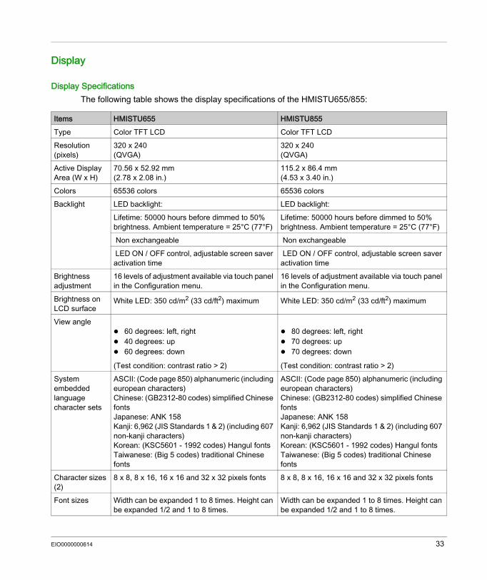
Display
Display SpecificationsThe following table shows the display specifications of the HMISTU655/855:
Items HMISTU655 HMISTU855Type Color TFT LCD Color TFT LCDResolution (pixels)
320 x 240(QVGA)
320 x 240(QVGA)
Active Display Area (W x H)
70.56 x 52.92 mm(2.78 x 2.08 in.)
115.2 x 86.4 mm(4.53 x 3.40 in.)
Colors 65536 colors 65536 colorsBacklight LED backlight: LED backlight:
Lifetime: 50000 hours before dimmed to 50% brightness. Ambient temperature = 25°C (77°F)
Lifetime: 50000 hours before dimmed to 50% brightness. Ambient temperature = 25°C (77°F)
Non exchangeable Non exchangeable LED ON / OFF control, adjustable screen saver activation time
LED ON / OFF control, adjustable screen saver activation time
Brightness adjustment
16 levels of adjustment available via touch panel in the Configuration menu.
16 levels of adjustment available via touch panel in the Configuration menu.
Brightness on LCD surface
White LED: 350 cd/m2 (33 cd/ft2) maximum White LED: 350 cd/m2 (33 cd/ft2) maximum
View angle 60 degrees: left, right 40 degrees: up 60 degrees: down
(Test condition: contrast ratio > 2)
80 degrees: left, right 70 degrees: up 70 degrees: down
(Test condition: contrast ratio > 2)System embedded language character sets
ASCII: (Code page 850) alphanumeric (including european characters) Chinese: (GB2312-80 codes) simplified Chinese fonts Japanese: ANK 158Kanji: 6,962 (JIS Standards 1 & 2) (including 607 non-kanji characters)Korean: (KSC5601 - 1992 codes) Hangul fontsTaiwanese: (Big 5 codes) traditional Chinese fonts
ASCII: (Code page 850) alphanumeric (including european characters) Chinese: (GB2312-80 codes) simplified Chinese fonts Japanese: ANK 158Kanji: 6,962 (JIS Standards 1 & 2) (including 607 non-kanji characters)Korean: (KSC5601 - 1992 codes) Hangul fontsTaiwanese: (Big 5 codes) traditional Chinese fonts
Character sizes (2)
8 x 8, 8 x 16, 16 x 16 and 32 x 32 pixels fonts 8 x 8, 8 x 16, 16 x 16 and 32 x 32 pixels fonts
Font sizes Width can be expanded 1 to 8 times. Height can be expanded 1/2 and 1 to 8 times.
Width can be expanded 1 to 8 times. Height can be expanded 1/2 and 1 to 8 times.
EIO0000000614 33
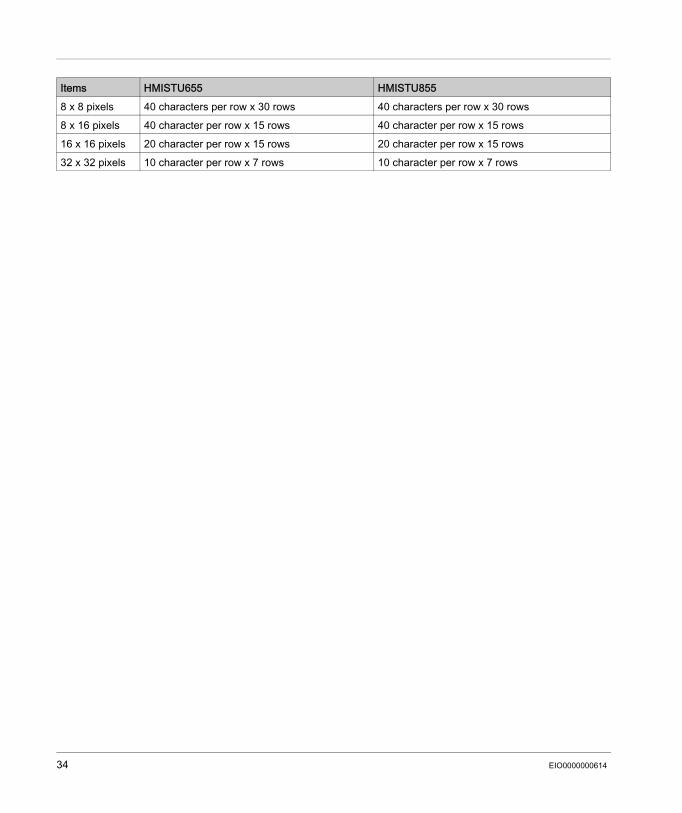
8 x 8 pixels 40 characters per row x 30 rows 40 characters per row x 30 rows8 x 16 pixels 40 character per row x 15 rows 40 character per row x 15 rows16 x 16 pixels 20 character per row x 15 rows 20 character per row x 15 rows32 x 32 pixels 10 character per row x 7 rows 10 character per row x 7 rows
Items HMISTU655 HMISTU855
34 EIO0000000614

Memory, Clock, and Touch Panel
MemoryThe following table shows the memory specifications of HMISTU655/855:
Memory Back-up Management in FRAMDetected alarms data are saved: automatically every hour in the back-up memory. upon user request through Vijeo Designer application design.
ClockVariations in operating conditions can cause a clock shift from -380 to +90 seconds per month.
Touch PanelThe following table shows the touch panel specifications of HMISTU655/855:
Items SpecificationApplication flash 32 MBData backup in FRAM 64 KBApplication run DRAM 64 MB
Items SpecificationType Analog resistance film type (Metal Tab, Golden
Plated)Lifetime 1 million touches or more
EIO0000000614 35
Interface Specifications
Section 2.3Interface Specifications
OverviewThis section presents the interface specifications of the HMISTU655/855 units.
What Is in This Section?This section contains the following topics:
Topic PageInterface Specifications 37Specifications of Serial Interface COM1 38
36 EIO0000000614
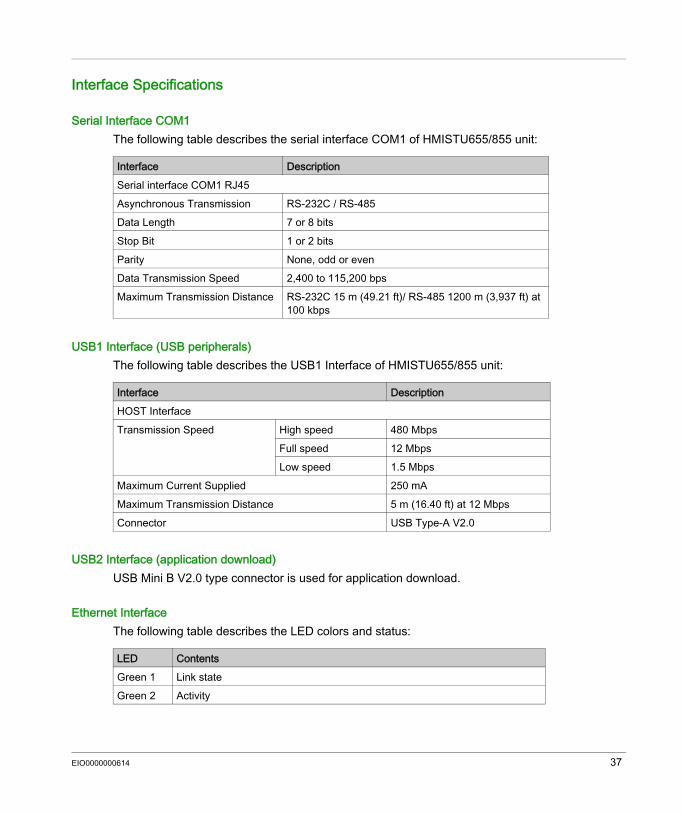
Interface Specifications
Serial Interface COM1The following table describes the serial interface COM1 of HMISTU655/855 unit:
USB1 Interface (USB peripherals)The following table describes the USB1 Interface of HMISTU655/855 unit:
USB2 Interface (application download)USB Mini B V2.0 type connector is used for application download.
Ethernet InterfaceThe following table describes the LED colors and status:
Interface DescriptionSerial interface COM1 RJ45Asynchronous Transmission RS-232C / RS-485Data Length 7 or 8 bitsStop Bit 1 or 2 bitsParity None, odd or evenData Transmission Speed 2,400 to 115,200 bpsMaximum Transmission Distance RS-232C 15 m (49.21 ft)/ RS-485 1200 m (3,937 ft) at
100 kbps
Interface DescriptionHOST InterfaceTransmission Speed High speed 480 Mbps
Full speed 12 MbpsLow speed 1.5 Mbps
Maximum Current Supplied 250 mAMaximum Transmission Distance 5 m (16.40 ft) at 12 MbpsConnector USB Type-A V2.0
LED ContentsGreen 1 Link stateGreen 2 Activity
EIO0000000614 37
38 EIO0000000614
Specifications of Serial Interface COM1
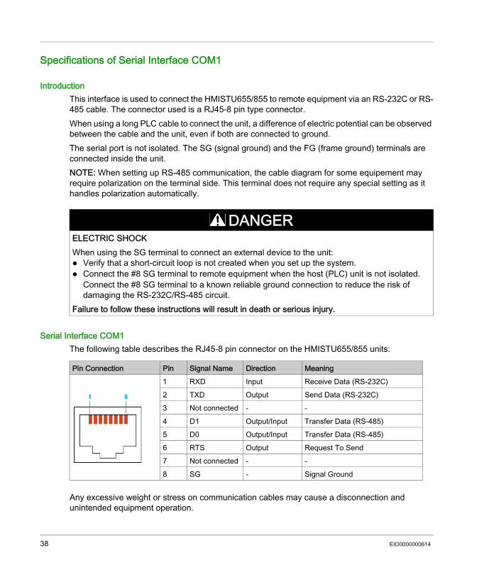
IntroductionThis interface is used to connect the HMISTU655/855 to remote equipment via an RS-232C or RS-485 cable. The connector used is a RJ45-8 pin type connector.When using a long PLC cable to connect the unit, a difference of electric potential can be observed between the cable and the unit, even if both are connected to ground.The serial port is not isolated. The SG (signal ground) and the FG (frame ground) terminals are connected inside the unit.NOTE: When setting up RS-485 communication, the cable diagram for some equipement may require polarization on the terminal side. This terminal does not require any special setting as it handles polarization automatically.
Serial Interface COM1The following table describes the RJ45-8 pin connector on the HMISTU655/855 units:
Any excessive weight or stress on communication cables may cause a disconnection and unintended equipment operation.
DANGERELECTRIC SHOCKWhen using the SG terminal to connect an external device to the unit: Verify that a short-circuit loop is not created when you set up the system. Connect the #8 SG terminal to remote equipment when the host (PLC) unit is not isolated.
Connect the #8 SG terminal to a known reliable ground connection to reduce the risk of damaging the RS-232C/RS-485 circuit.
Failure to follow these instructions will result in death or serious injury.
Pin Connection Pin Signal Name Direction Meaning 1 RXD Input Receive Data (RS-232C)
2 TXD Output Send Data (RS-232C)3 Not connected - -4 D1 Output/Input Transfer Data (RS-485)5 D0 Output/Input Transfer Data (RS-485)6 RTS Output Request To Send7 Not connected - -8 SG - Signal Ground
EIO0000000614 39
CAUTIONLOSS OF COMMUNICATIONWhen using HMISTU655/855: All connections to the communication ports on the bottom and sides of the unit must not put
excessive stress on the ports. Securely attach communication cables to the panel or cabinet. Use only RJ45 cables with a locking tab in good condition.Failure to follow these instructions can result in injury or equipment damage.
Dimensions
Section 2.4Dimensions
HMISTU655/855
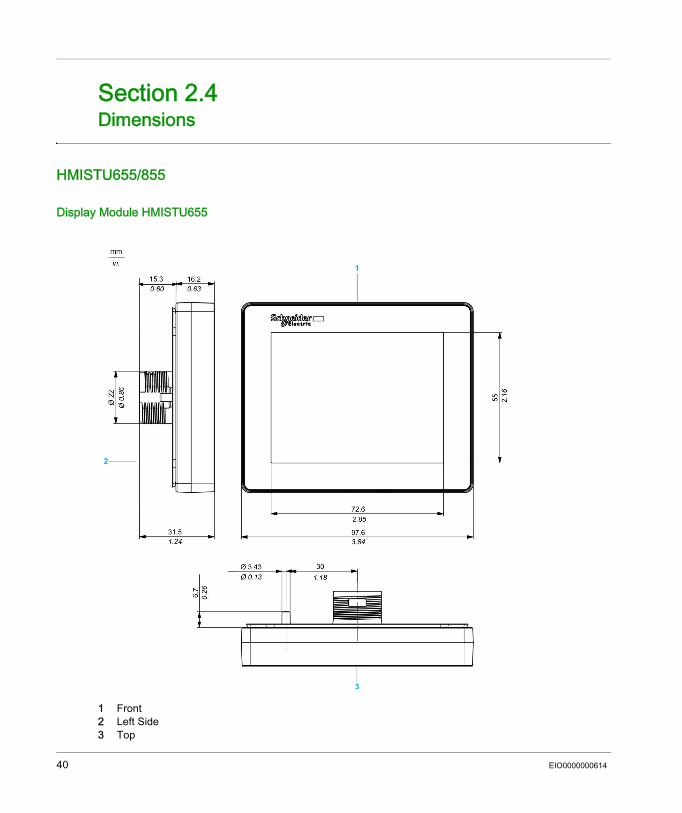
Display Module HMISTU655
1 Front2 Left Side3 Top
40 EIO0000000614
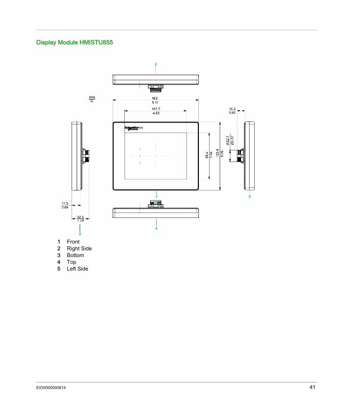
Display Module HMISTU855
1 Front2 Right Side3 Bottom4 Top5 Left Side
EIO0000000614 41
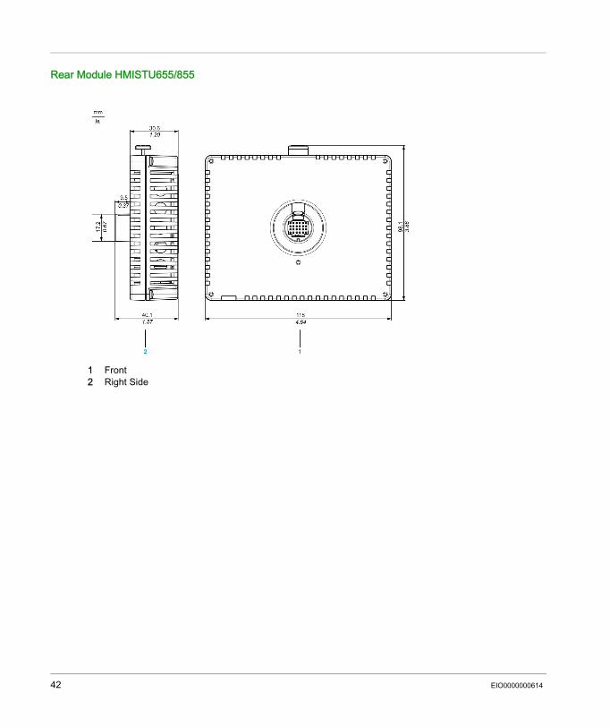
Rear Module HMISTU655/855
1 Front2 Right Side
42 EIO0000000614
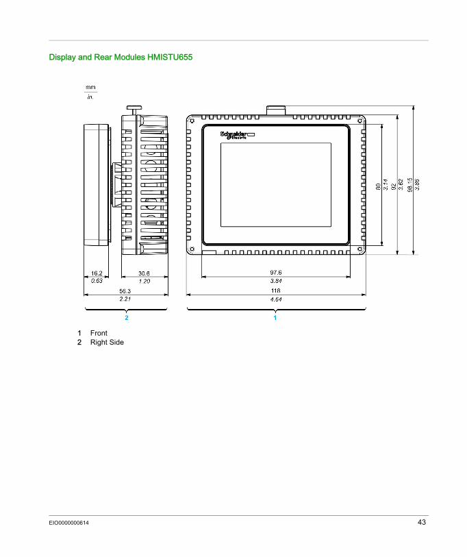
Display and Rear Modules HMISTU655
1 Front2 Right Side
EIO0000000614 43

Display and Rear Modules HMISTU855
1 Front2 Right side3 Top4 Bottom5 Left side
44 EIO0000000614
Harmony HMISTU655/855
EIO0000000614
Installation and Wiring
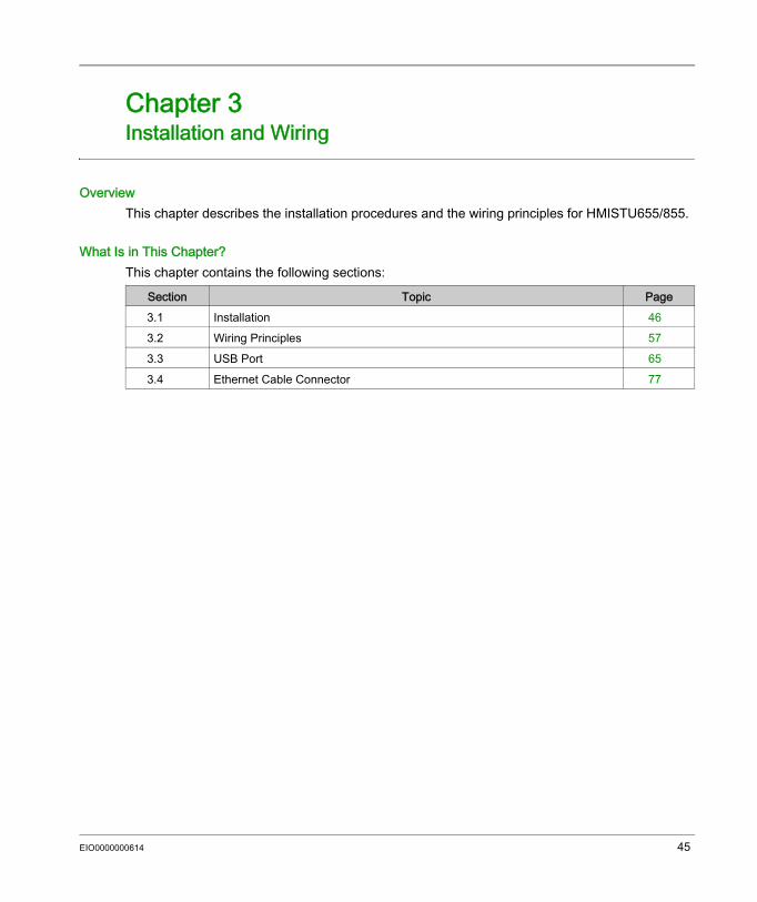
Chapter 3Installation and Wiring
OverviewThis chapter describes the installation procedures and the wiring principles for HMISTU655/855.
What Is in This Chapter?This chapter contains the following sections:
Section Topic Page3.1 Installation 463.2 Wiring Principles 573.3 USB Port 653.4 Ethernet Cable Connector 77
EIO0000000614 45
Installation
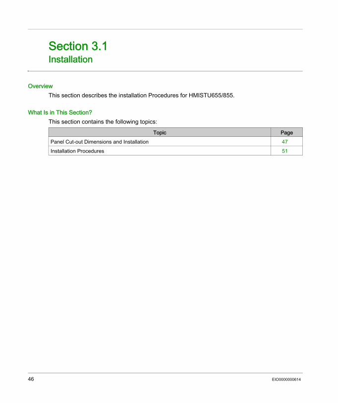
Section 3.1Installation
OverviewThis section describes the installation Procedures for HMISTU655/855.
What Is in This Section?This section contains the following topics:
Topic PagePanel Cut-out Dimensions and Installation 47Installation Procedures 51
46 EIO0000000614
Panel Cut-out Dimensions and Installation
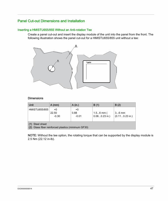
Inserting a HMISTU655/855 Without an Anti-rotation TeeCreate a panel cut-out and insert the display module of the unit into the panel from the front. The following illustration shows the panel cut-out for a HMISTU655/855 unit without a tee:
Dimensions
NOTE: Without the tee option, the rotating torque that can be supported by the display module is 2.5 Nm (22.12 in-lb).
Unit A (mm) A (in.) B (1) B (2)HMISTU655/855 +0
22.50-0.30
+00.88
-0.011.5...6 mm ( 0.06...0.23 in.)
3...6 mm (0.11...0.23 in.)
(1) Steel sheet (2) Glass fiber reinforced plastics (minimum GF30)
EIO0000000614 47
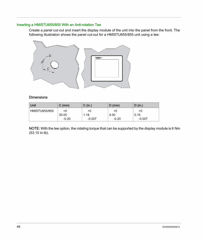
Inserting a HMISTU655/855 With an Anti-rotation TeeCreate a panel cut-out and insert the display module of the unit into the panel from the front. The following illustration shows the panel cut-out for a HMISTU655/855 unit using a tee:
Dimensions
NOTE: With the tee option, the rotating torque that can be supported by the display module is 6 Nm (53.10 in-lb).
Unit C (mm) C (in.) D (mm) D (in.)HMISTU655/855 +0
30.00-0.20
+01.18
-0.007
+04.00
-0.20
+00.15
-0.007
48 EIO0000000614
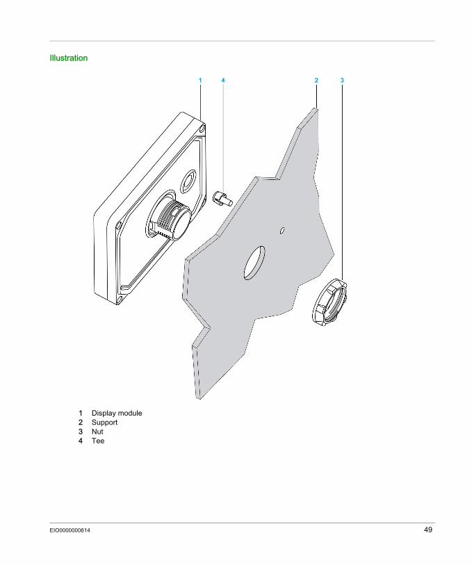
Illustration
1 Display module2 Support3 Nut4 Tee
EIO0000000614 49
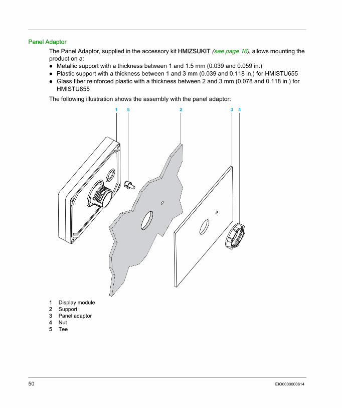
Panel AdaptorThe Panel Adaptor, supplied in the accessory kit HMIZSUKIT (see page 16), allows mounting the product on a: Metallic support with a thickness between 1 and 1.5 mm (0.039 and 0.059 in.) Plastic support with a thickness between 1 and 3 mm (0.039 and 0.118 in.) for HMISTU655 Glass fiber reinforced plastic with a thickness between 2 and 3 mm (0.078 and 0.118 in.) for
HMISTU855The following illustration shows the assembly with the panel adaptor:
1 Display module2 Support3 Panel adaptor4 Nut5 Tee
50 EIO0000000614
Installation Procedures
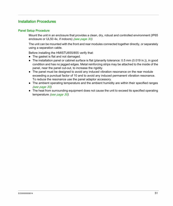
Panel Setup ProcedureMount the unit in an enclosure that provides a clean, dry, robust and controlled environment (IP65 enclosure or UL50 4x, if indoors) (see page 30).The unit can be mounted with the front and rear modules connected together directly, or separately using a separation cable.Before installing the HMISTU655/855 verify that: The gasket is flat and not damaged. The installation panel or cabinet surface is flat (planarity tolerance: 0.5 mm (0.019 in.)), in good
condition and has no jagged edges. Metal reinforcing strips may be attached to the inside of the panel, near the panel cut-out, to increase the rigidity.
The panel must be designed to avoid any induced vibration resonance on the rear module exceeding a punctual factor of 10 and to avoid any induced permanent vibration resonance.To reduce the resonance use the panel adaptor accessory.
The ambient operating temperature and the ambient humidity are within their specified ranges (see page 30).
The heat from surrounding equipment does not cause the unit to exceed its specified operating temperature (see page 30).
EIO0000000614 51
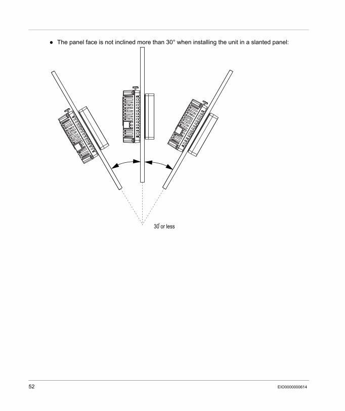
The panel face is not inclined more than 30° when installing the unit in a slanted panel:
30 or less
52 EIO0000000614
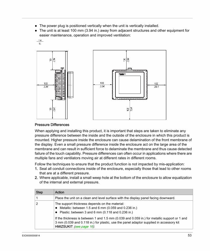
The power plug is positioned vertically when the unit is vertically installed. The unit is at least 100 mm (3.94 in.) away from adjacent structures and other equipment for
easier maintenance, operation and improved ventilation:
Pressure DifferencesWhen applying and installing this product, it is important that steps are taken to eliminate any pressure difference between the inside and the outside of the enclosure in which this product is mounted. Higher pressure inside the enclosure can cause delamination of the front membrane of the display. Even a small pressure difference inside the enclosure act on the large area of the membrane and can result in sufficient force to delaminate the membrane and thus cause detected failure of the touch capability. Pressure differences can often occur in applications where there are multiple fans and ventilators moving air at different rates in different rooms. Follow the techniques to ensure that the product function is not impacted by mis-application:1. Seal all conduit connections inside of the enclosure, especially those that lead to other rooms
that are at a different pressure.2. Where applicable, install a small weep hole at the bottom of the enclosure to allow equalization
of the internal and external pressure.
Step Action1 Place the unit on a clean and level surface with the display panel facing downward.2 The support thickness depends on the material:
Metallic: between 1.5 and 6 mm (0.059 and 0.236 in.) Plastic: between 3 and 6 mm (0.118 and 0.236 in.)
If the thickness is between 1 and 1.5 mm (0.039 and 0.059 in.) for metallic support or 1 and 3 mm (0.039 and 0.118 in.) for plastic, use the panel adaptor supplied in accessory kit HMIZSUKIT (see page 16).
EIO0000000614 53
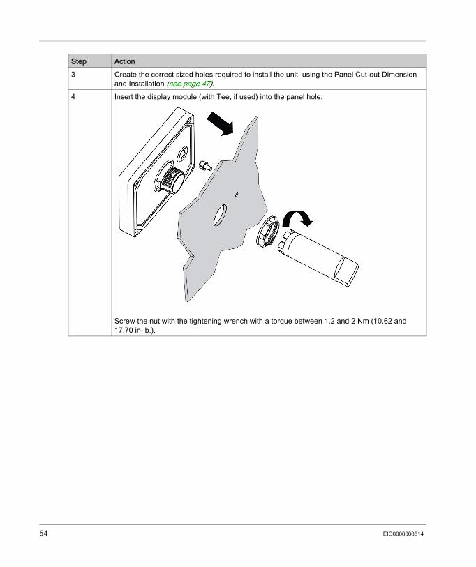
3 Create the correct sized holes required to install the unit, using the Panel Cut-out Dimension and Installation (see page 47).
4 Insert the display module (with Tee, if used) into the panel hole:
Screw the nut with the tightening wrench with a torque between 1.2 and 2 Nm (10.62 and 17.70 in-lb.).
Step Action
54 EIO0000000614
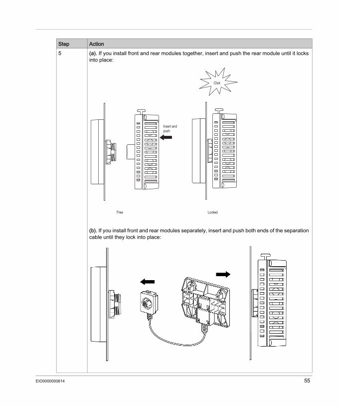
5 (a). If you install front and rear modules together, insert and push the rear module until it locks into place:
(b). If you install front and rear modules separately, insert and push both ends of the separation cable until they lock into place:
Step Action
Click
Insert andpush
Free Locked
EIO0000000614 55
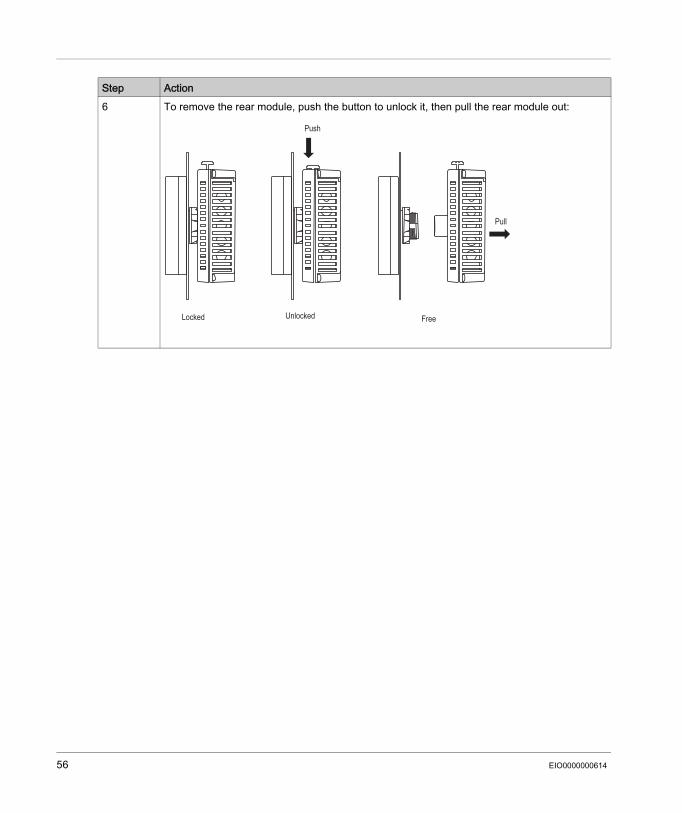
6 To remove the rear module, push the button to unlock it, then pull the rear module out:Step Action
Push
Pull
Locked Unlocked Free
56 EIO0000000614
Wiring Principles
Section 3.2Wiring Principles
OverviewThis section presents HMISTU655/855 wiring principles.
What Is in This Section?This section contains the following topics:
Topic PageConnecting the Power Cord 58Connecting the Power Supply 61Grounding 63
EIO0000000614 57
Connecting the Power Cord
IntroductionFollow these instructions when supplying power to the unit: When the frame ground (FG) terminal is connected, verify the wire is grounded. Not grounding
the unit can result in excessive Electromagnetic Interference (EMI). Grounding is required to meet EMC level immunity.
The shield ground (SG) and FG terminals are connected internally in the unit. Remove power before wiring to the power terminals of the unit. The unit uses only 24 Vdc power. Using any other level of power can damage both the power
supply and the unit. Since the unit is not equipped with a power switch, connect a power switch to the unit’s power
supply.
Power Cord PreparationBefore using your power cord: Verify the ground wire is the same gauge or heavier than the power wires. Do not use aluminum wires for the power cord for power supply. If the conductor end (individual) wires are not twisted correctly, the end wires may either short
loop to each other or against an electrode. To avoid this, use D25CE/AZ5CE cable ends. Use wires that are 0.2 to 2.5 mm2 (24 - 12 AWG) for the power cord, and twist the wire ends
before attaching the terminals. The conductor type is solid or stranded wire. To reduce electromagnetic noise, make the power cord as short as possible.
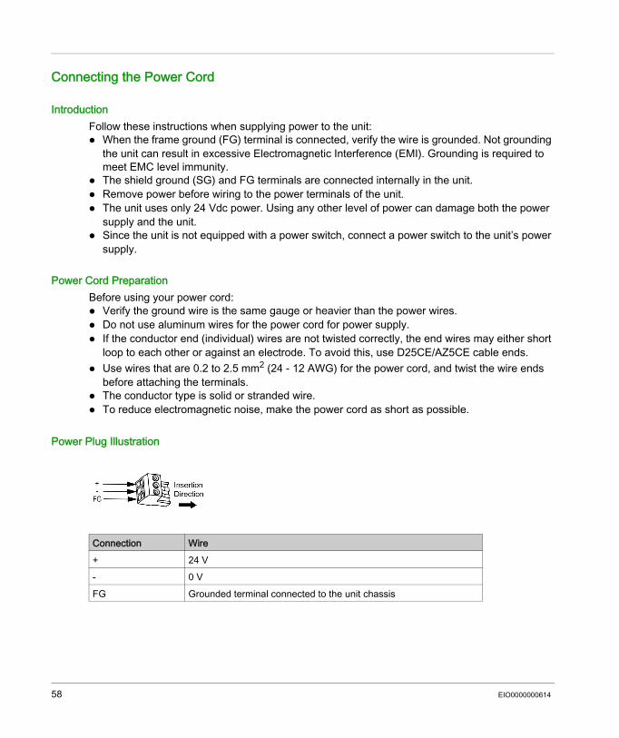
Power Plug Illustration
Connection Wire+ 24 V- 0 VFG Grounded terminal connected to the unit chassis
58 EIO0000000614
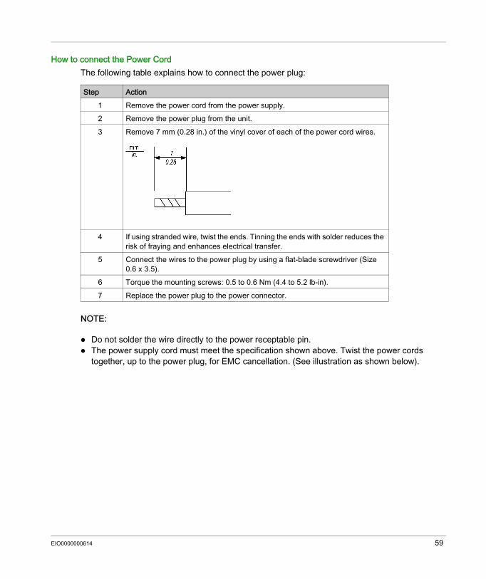
How to connect the Power CordThe following table explains how to connect the power plug:
NOTE: Do not solder the wire directly to the power receptable pin. The power supply cord must meet the specification shown above. Twist the power cords
together, up to the power plug, for EMC cancellation. (See illustration as shown below).
Step Action1 Remove the power cord from the power supply.2 Remove the power plug from the unit.3 Remove 7 mm (0.28 in.) of the vinyl cover of each of the power cord wires.
4 If using stranded wire, twist the ends. Tinning the ends with solder reduces the risk of fraying and enhances electrical transfer.
5 Connect the wires to the power plug by using a flat-blade screwdriver (Size 0.6 x 3.5).
6 Torque the mounting screws: 0.5 to 0.6 Nm (4.4 to 5.2 lb-in).7 Replace the power plug to the power connector.
EIO0000000614 59
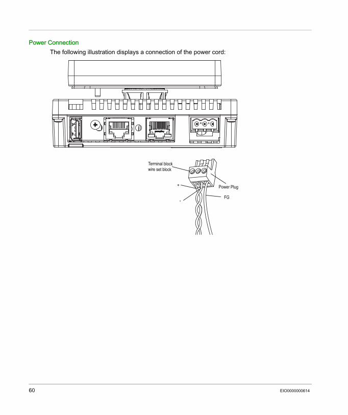
Power ConnectionThe following illustration displays a connection of the power cord:
+
-FG
Power Plug
Terminal blockwire set block
60 EIO0000000614

Connecting the Power Supply
Precautions Connect the power cord to the power connector on the side of the unit using the power plug. Use a regulated power supply with a Class 2 power supply between the line and the ground. Do not bundle the power supply cord with, or keep close to, main circuit lines (high voltage, high
current), or input/output signal lines. Connect a lightning surge absorber to handle power surges.Excessive stress on the power connection or attempting to install a unit with the power cables connected may disconnect or cause damage to the power connections. This can cause short circuits, fire or unintended equipment operation.
WARNINGSHORT CIRCUITS, FIRE, OR UNINTENDED EQUIPMENT OPERATION Securely attach power cables to the panel or cabinet. Use the designated torque to tighten the unit terminal block screws. Install and fasten unit on installation panel or cabinet prior to connecting Power Supply and
Communication lines. Failure to follow these instructions can result in death, serious injury, or equipment damage.
EIO0000000614 61
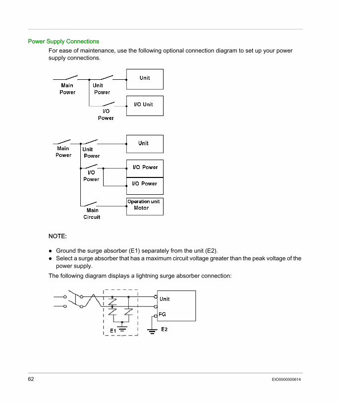
Power Supply ConnectionsFor ease of maintenance, use the following optional connection diagram to set up your power supply connections.
NOTE: Ground the surge absorber (E1) separately from the unit (E2). Select a surge absorber that has a maximum circuit voltage greater than the peak voltage of the
power supply.The following diagram displays a lightning surge absorber connection:
62 EIO0000000614
Grounding
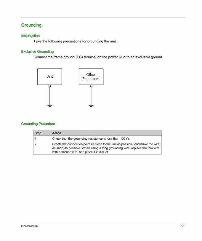
IntroductionTake the following precautions for grounding the unit.
Exclusive GroundingConnect the frame ground (FG) terminal on the power plug to an exclusive ground.
Grounding Procedure
Step Action1 Check that the grounding resistance is less than 100 Ω.2 Create the connection point as close to the unit as possible, and make the wire
as short as possible. When using a long grounding wire, replace the thin wire with a thicker wire, and place it in a duct.
EIO0000000614 63
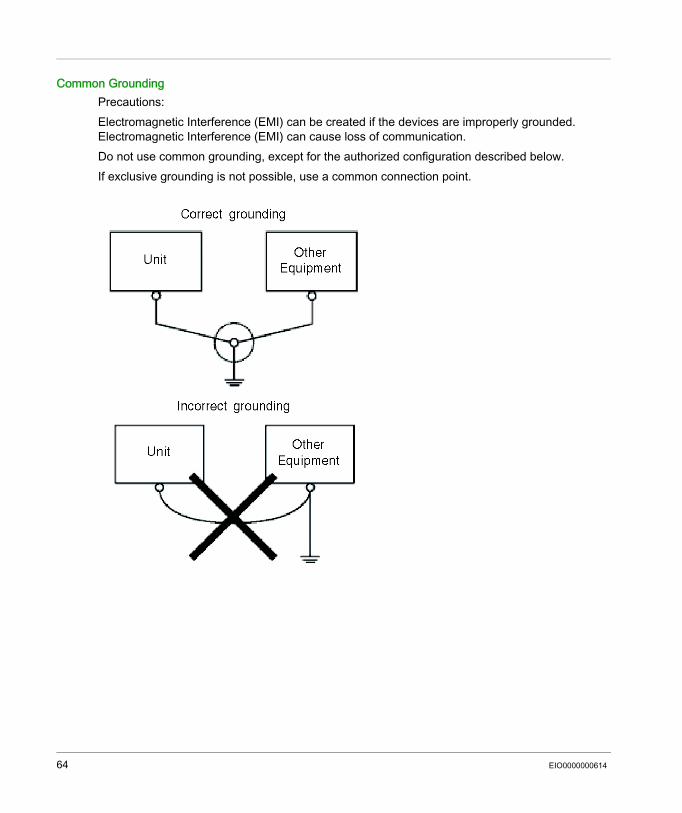
Common GroundingPrecautions:Electromagnetic Interference (EMI) can be created if the devices are improperly grounded. Electromagnetic Interference (EMI) can cause loss of communication.Do not use common grounding, except for the authorized configuration described below.If exclusive grounding is not possible, use a common connection point.
64 EIO0000000614
USB Port
Section 3.3USB Port
OverviewThis section presents the USB port.
What Is in This Section?This section contains the following topics:
Topic PageImportant Considerations When Using the USB Port 66USB Data Transfer Cable (BMXXCAUSBH018) - USB Driver Installation 67USB Standard A 69USB Mini-B 74
EIO0000000614 65
Important Considerations When Using the USB Port
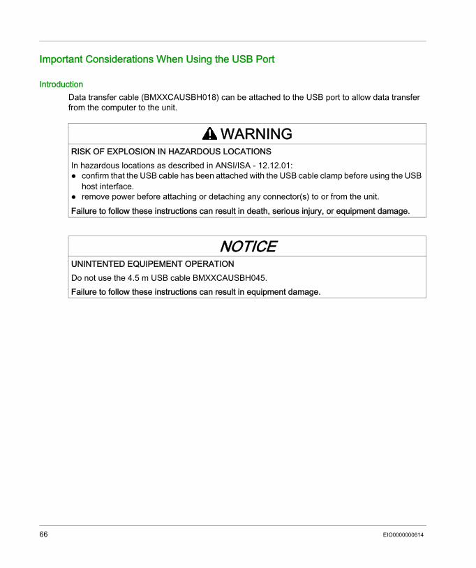
IntroductionData transfer cable (BMXXCAUSBH018) can be attached to the USB port to allow data transfer from the computer to the unit.
WARNINGRISK OF EXPLOSION IN HAZARDOUS LOCATIONSIn hazardous locations as described in ANSI/ISA - 12.12.01: confirm that the USB cable has been attached with the USB cable clamp before using the USB
host interface. remove power before attaching or detaching any connector(s) to or from the unit.Failure to follow these instructions can result in death, serious injury, or equipment damage.
NOTICEUNINTENTED EQUIPEMENT OPERATIONDo not use the 4.5 m USB cable BMXXCAUSBH045.Failure to follow these instructions can result in equipment damage.
66 EIO0000000614
USB Data Transfer Cable (BMXXCAUSBH018) - USB Driver Installation
Important informationFollow the procedure described below to avoid damage to the cable connector or the unit: Do not connect the USB data transfer cable until told to do so in the instructions. Insert the connector at the correct angle when connecting the USB data transfer cable to the
PC or to the unit. Hold the connector, not the cable itself when disconnecting the cable. Use the port designated during installation. If the cable is unplugged from the port designated
during installation and connected to a different port, the OS (Operating System) will not recognize the new port.
Restart the PC and quit all resident applications before re-installing the software if the installation does not complete successfully.
NOTE: Vijeo Designer must be installed before installing the USB driver.
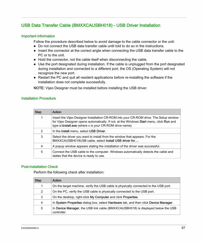
Installation Procedure
Post-Installation CheckPerform the following check after installation:
Step Action1 Insert the Vijeo Designer Installation CR-ROM into your CR-ROM drive. The Setup window
for Vijeo Designer opens automatically. If not, at the Windows Start menu, click Run and type x:\install.exe (where x is your CR-ROM drive name).
2 In the install menu, select USB Driver.3 Select the driver you want to install from the window that appears. For the
BMXXCAUSBH018USB cable, select Install USB driver for....4 A popup window appears stating the installation of the driver was successful.5 Connect the USB cable to the computer. Windows automatically detects the cable and
states that the device is ready to use.
Step Action1 On the target machine, verify the USB cable is physically connected to the USB port.2 On the PC, verify the USB cable is physically connected to the USB port.3 On the desktop, right-click My Computer and click Properties.4 In System Properties dialog box, select Hardware tab, and then click Device Manager. 5 In Device Manager, the USB link cable (BMXXCAUSBH018) is displayed below the USB
controller.
EIO0000000614 67
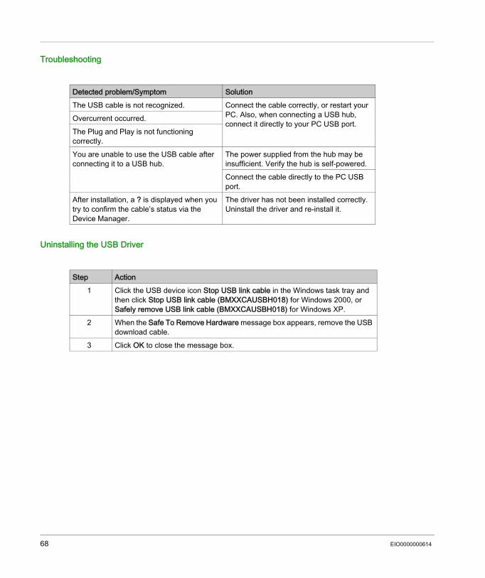
Troubleshooting
Uninstalling the USB Driver
Detected problem/Symptom SolutionThe USB cable is not recognized. Connect the cable correctly, or restart your
PC. Also, when connecting a USB hub, connect it directly to your PC USB port.
Overcurrent occurred.The Plug and Play is not functioning correctly.You are unable to use the USB cable after connecting it to a USB hub.
The power supplied from the hub may be insufficient. Verify the hub is self-powered.Connect the cable directly to the PC USB port.
After installation, a ? is displayed when you try to confirm the cable’s status via the Device Manager.
The driver has not been installed correctly. Uninstall the driver and re-install it.
Step Action1 Click the USB device icon Stop USB link cable in the Windows task tray and
then click Stop USB link cable (BMXXCAUSBH018) for Windows 2000, or Safely remove USB link cable (BMXXCAUSBH018) for Windows XP.
2 When the Safe To Remove Hardware message box appears, remove the USB download cable.
3 Click OK to close the message box.
68 EIO0000000614
USB Standard A
IntroductionWhen using a USB device, you can attach a USB holder to the USB interface on the side of the unit to prevent the USB cable from being disconnected.
WARNINGRISK OF EXPLOSION IN HAZARDOUS LOCATIONSIn hazardous locations as described in ANSI/ISA 12.12.01: confirm that the USB cable has been attached with the USB cable clamp before using the USB
host interface. remove power before attaching or detaching any connector(s) to or from the unit.Failure to follow these instructions can result in death, serious injury, or equipment damage.
EIO0000000614 69
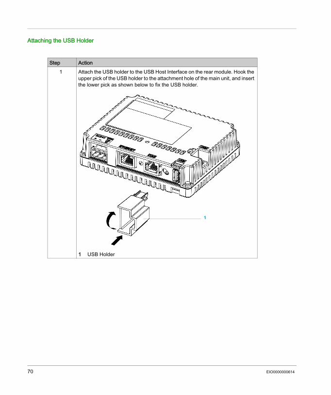
Attaching the USB Holder
Step Action1 Attach the USB holder to the USB Host Interface on the rear module. Hook the
upper pick of the USB holder to the attachment hole of the main unit, and insert the lower pick as shown below to fix the USB holder.
1 USB Holder
70 EIO0000000614
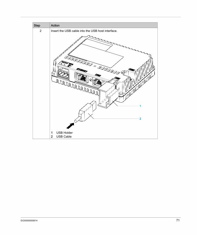
2 Insert the USB cable into the USB host interface.
1 USB Holder2 USB Cable
Step Action
EIO0000000614 71
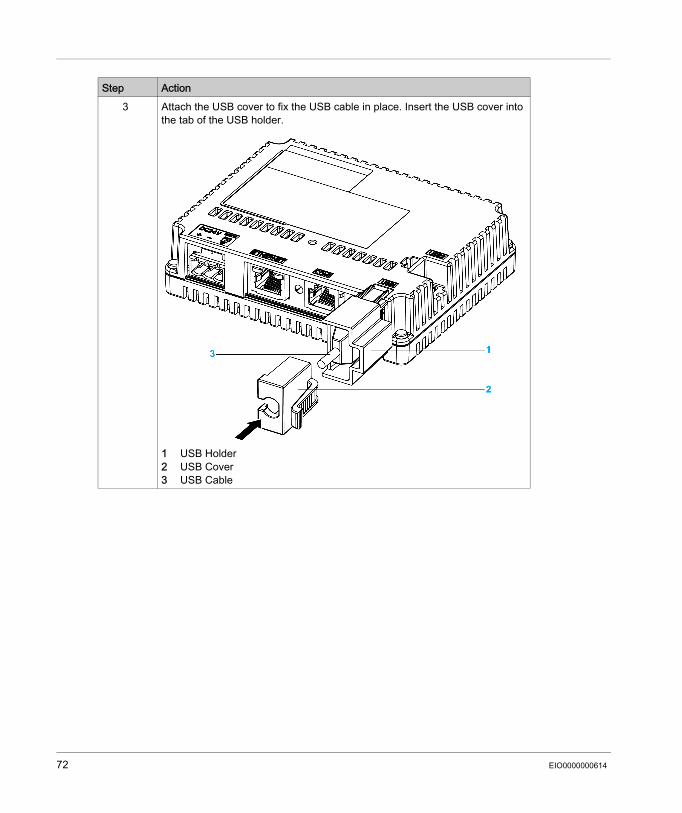
3 Attach the USB cover to fix the USB cable in place. Insert the USB cover into the tab of the USB holder.
1 USB Holder2 USB Cover3 USB Cable
Step Action
72 EIO0000000614
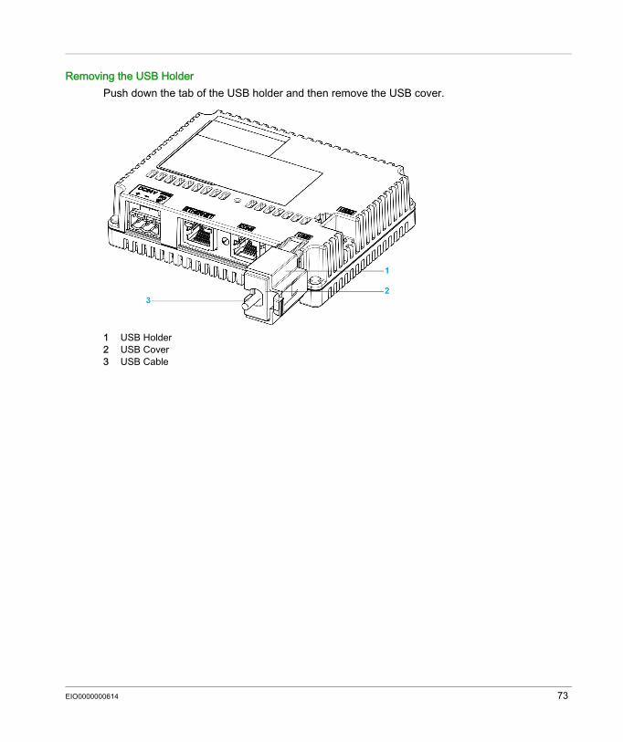
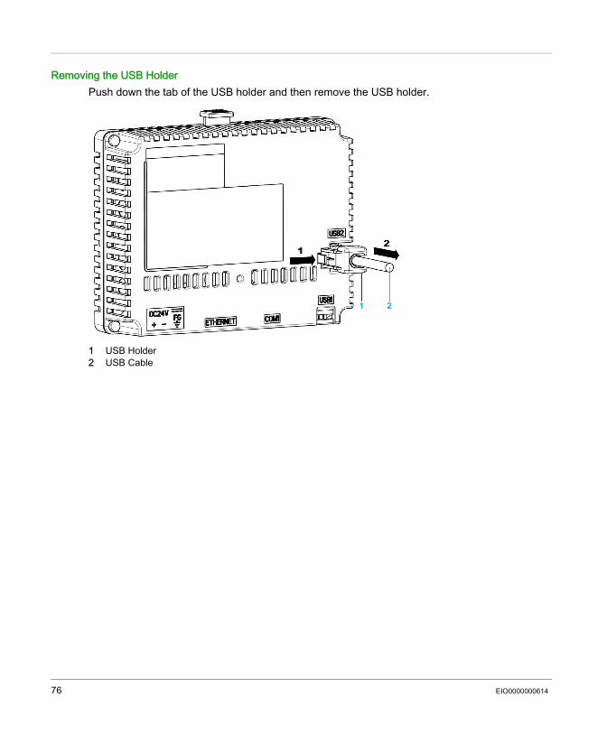
Removing the USB Holder Push down the tab of the USB holder and then remove the USB cover.
1 USB Holder2 USB Cover3 USB Cable
EIO0000000614 73
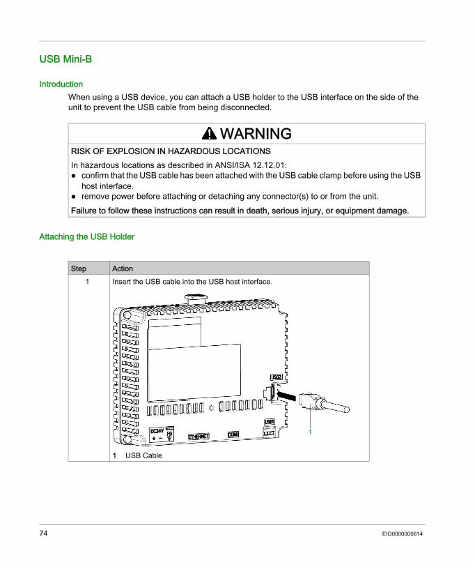
USB Mini-B
IntroductionWhen using a USB device, you can attach a USB holder to the USB interface on the side of the unit to prevent the USB cable from being disconnected.
Attaching the USB Holder
WARNINGRISK OF EXPLOSION IN HAZARDOUS LOCATIONSIn hazardous locations as described in ANSI/ISA 12.12.01: confirm that the USB cable has been attached with the USB cable clamp before using the USB
host interface. remove power before attaching or detaching any connector(s) to or from the unit.Failure to follow these instructions can result in death, serious injury, or equipment damage.
Step Action1 Insert the USB cable into the USB host interface.
1 USB Cable
74 EIO0000000614
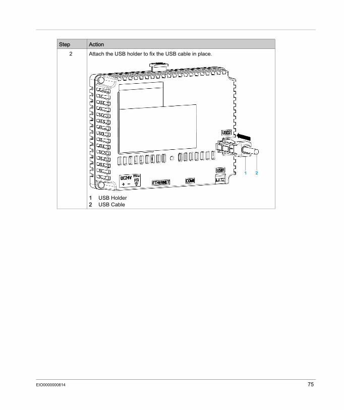
2 Attach the USB holder to fix the USB cable in place.
1 USB Holder2 USB Cable
Step Action
EIO0000000614 75
Removing the USB Holder Push down the tab of the USB holder and then remove the USB holder.
1 USB Holder2 USB Cable
76 EIO0000000614
Ethernet Cable Connector
Section 3.4Ethernet Cable Connector
Presentation
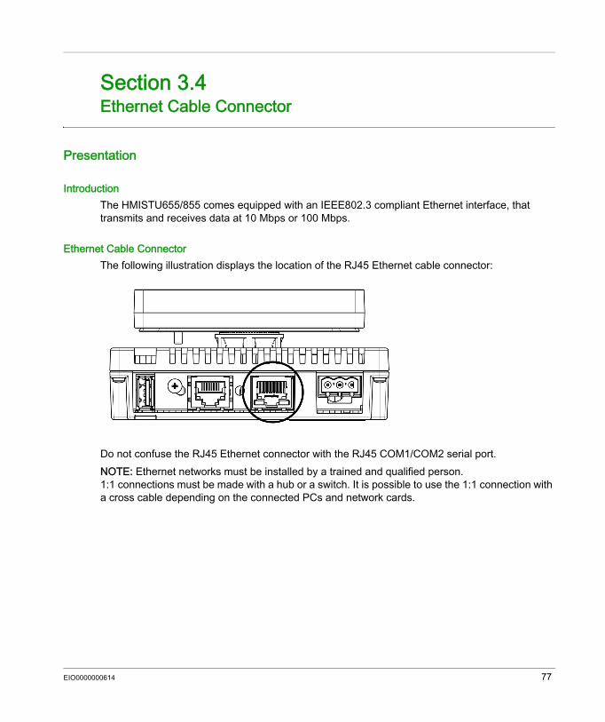
IntroductionThe HMISTU655/855 comes equipped with an IEEE802.3 compliant Ethernet interface, that transmits and receives data at 10 Mbps or 100 Mbps.
Ethernet Cable ConnectorThe following illustration displays the location of the RJ45 Ethernet cable connector:
Do not confuse the RJ45 Ethernet connector with the RJ45 COM1/COM2 serial port.NOTE: Ethernet networks must be installed by a trained and qualified person.1:1 connections must be made with a hub or a switch. It is possible to use the 1:1 connection with a cross cable depending on the connected PCs and network cards.
EIO0000000614 77

78 EIO0000000614
Harmony HMISTU655/855
EIO0000000614
Settings
Part IISettings
OverviewThis part describes the settings available on the target machine as well as how to debug the unit.
What Is in This Part?This part contains the following chapters:
Chapter Chapter Name Page4 Configuring the Unit 815 Troubleshooting 936 Maintenance 99
EIO0000000614 79

80 EIO0000000614
Harmony HMISTU655/855
EIO0000000614
Configuring the Unit
Chapter 4Configuring the Unit
OverviewThis chapter presents the settings on the HMISTU655/855 units.
What Is in This Chapter?This chapter contains the following topics:
Topic PageTypes of Settings 82System Settings 83Offline Settings 87Diagnostics Settings 90
EIO0000000614 81
Types of Settings
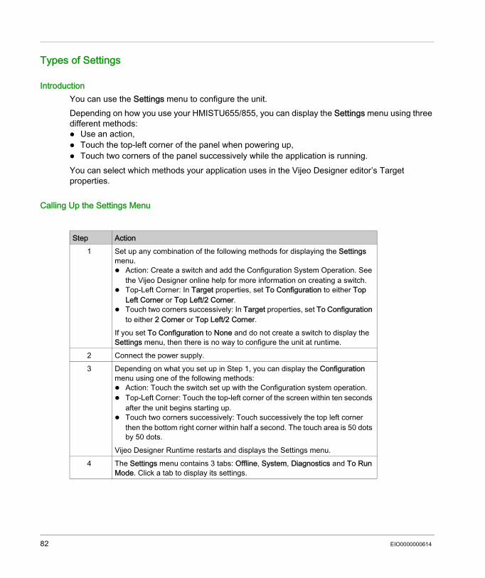
IntroductionYou can use the Settings menu to configure the unit.Depending on how you use your HMISTU655/855, you can display the Settings menu using three different methods: Use an action, Touch the top-left corner of the panel when powering up, Touch two corners of the panel successively while the application is running.You can select which methods your application uses in the Vijeo Designer editor’s Target properties.
Calling Up the Settings Menu
Step Action1 Set up any combination of the following methods for displaying the Settings
menu. Action: Create a switch and add the Configuration System Operation. See
the Vijeo Designer online help for more information on creating a switch. Top-Left Corner: In Target properties, set To Configuration to either Top
Left Corner or Top Left/2 Corner. Touch two corners successively: In Target properties, set To Configuration
to either 2 Corner or Top Left/2 Corner.If you set To Configuration to None and do not create a switch to display the Settings menu, then there is no way to configure the unit at runtime.
2 Connect the power supply.3 Depending on what you set up in Step 1, you can display the Configuration
menu using one of the following methods: Action: Touch the switch set up with the Configuration system operation. Top-Left Corner: Touch the top-left corner of the screen within ten seconds
after the unit begins starting up. Touch two corners successively: Touch successively the top left corner
then the bottom right corner within half a second. The touch area is 50 dots by 50 dots.
Vijeo Designer Runtime restarts and displays the Settings menu.4 The Settings menu contains 3 tabs: Offline, System, Diagnostics and To Run
Mode. Click a tab to display its settings.
82 EIO0000000614
System Settings
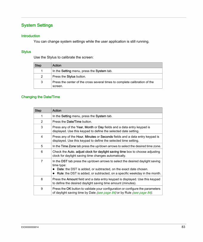
IntroductionYou can change system settings while the user application is still running.
StylusUse the Stylus to calibrate the screen:
Changing the Date/Time
Step Action1 In the Setting menu, press the System tab.2 Press the Stylus button.3 Press the center of the cross several times to complete calibration of the
screen.
Step Action1 In the Setting menu, press the System tab.2 Press the Date/Time button.3 Press any of the Year, Month or Day fields and a data entry keypad is
displayed. Use this keypad to define the selected date setting.4 Press any of the Hour, Minutes or Seconds fields and a data entry keypad is
displayed. Use this keypad to define the selected time setting.5 In the Time Zone tab press the up/down arrows to select the desired time zone.6 Check the Auto. adjust clock for daylight saving time box to choose adjusting
clock for daylight saving time changes automatically.7 In the DST tab press the up/down arrows to select the desired daylight saving
time type: Date: the DST is added, or subtracted, on the exact date chosen. Rule: the DST is added, or subtracted, on a specific weekday in the month.
8 Press the Amount field and a data entry keypad is displayed. Use this keypad to define the desired daylight saving time amount (minutes).
9 Press the OK button to validate your configuration or configure the parameters of daylight saving time by Date (see page 84) or by Rule (see page 84).
EIO0000000614 83
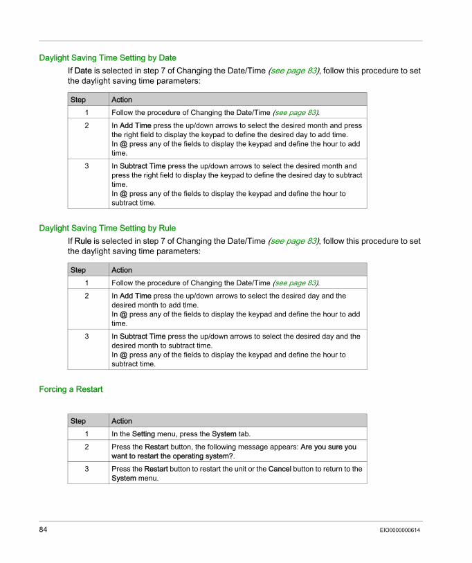
Daylight Saving Time Setting by DateIf Date is selected in step 7 of Changing the Date/Time (see page 83), follow this procedure to set the daylight saving time parameters:
Daylight Saving Time Setting by RuleIf Rule is selected in step 7 of Changing the Date/Time (see page 83), follow this procedure to set the daylight saving time parameters:
Forcing a Restart
Step Action1 Follow the procedure of Changing the Date/Time (see page 83).2 In Add Time press the up/down arrows to select the desired month and press
the right field to display the keypad to define the desired day to add time.In @ press any of the fields to display the keypad and define the hour to add time.
3 In Subtract Time press the up/down arrows to select the desired month and press the right field to display the keypad to define the desired day to subtract time.In @ press any of the fields to display the keypad and define the hour to subtract time.
Step Action1 Follow the procedure of Changing the Date/Time (see page 83).2 In Add Time press the up/down arrows to select the desired day and the
desired month to add tlme.In @ press any of the fields to display the keypad and define the hour to add time.
3 In Subtract Time press the up/down arrows to select the desired day and the desired month to subtract time.In @ press any of the fields to display the keypad and define the hour to subtract time.
Step Action1 In the Setting menu, press the System tab.2 Press the Restart button, the following message appears: Are you sure you
want to restart the operating system?.3 Press the Restart button to restart the unit or the Cancel button to return to the
System menu.
84 EIO0000000614
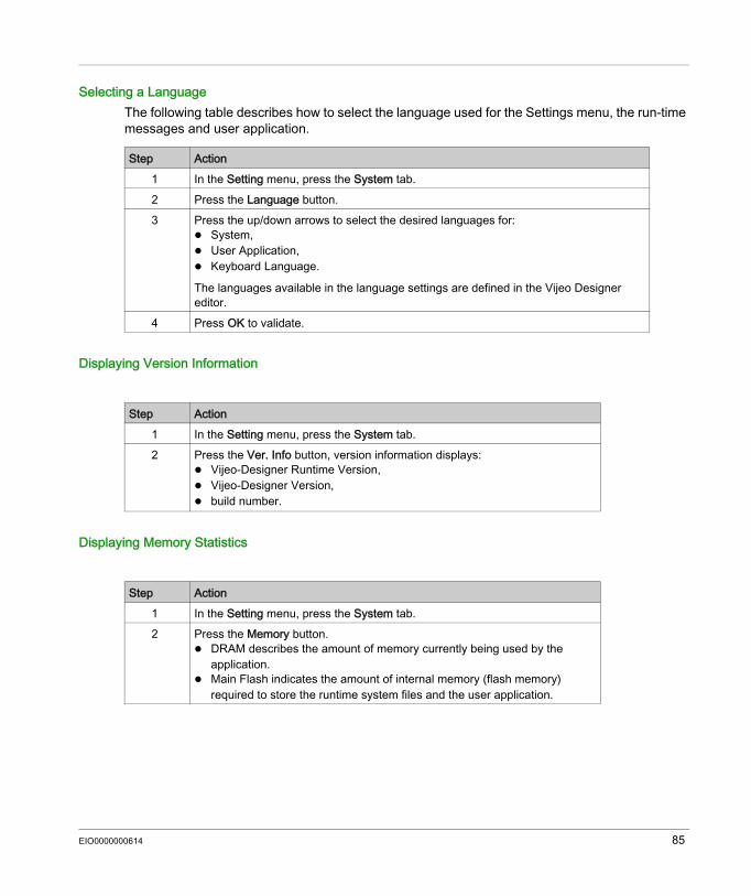
Selecting a LanguageThe following table describes how to select the language used for the Settings menu, the run-time messages and user application.
Displaying Version Information
Displaying Memory Statistics
Step Action1 In the Setting menu, press the System tab.2 Press the Language button.3 Press the up/down arrows to select the desired languages for:
System, User Application, Keyboard Language.
The languages available in the language settings are defined in the Vijeo Designer editor.
4 Press OK to validate.
Step Action1 In the Setting menu, press the System tab.2 Press the Ver. Info button, version information displays:
Vijeo-Designer Runtime Version, Vijeo-Designer Version, build number.
Step Action1 In the Setting menu, press the System tab.2 Press the Memory button.
DRAM describes the amount of memory currently being used by the application.
Main Flash indicates the amount of internal memory (flash memory) required to store the runtime system files and the user application.
EIO0000000614 85
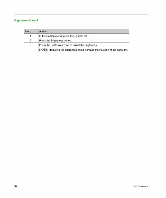
Brightness Control
Step Action1 In the Setting menu, press the System tab.2 Press the Brightness button.3 Press the up/down arrows to adjust the brightness.
NOTE: Reducing the brightness could increase the life span of the backlight.
86 EIO0000000614
Offline Settings
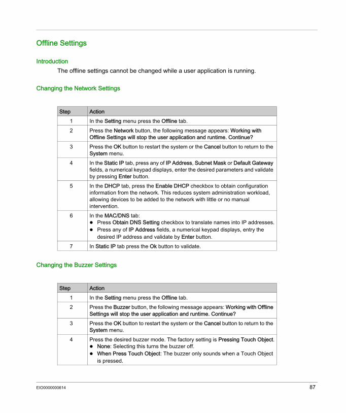
IntroductionThe offline settings cannot be changed while a user application is running.
Changing the Network Settings
Changing the Buzzer Settings
Step Action1 In the Setting menu press the Offline tab.2 Press the Network button, the following message appears: Working with
Offline Settings will stop the user application and runtime. Continue? 3 Press the OK button to restart the system or the Cancel button to return to the
System menu.4 In the Static IP tab, press any of IP Address, Subnet Mask or Default Gateway
fields, a numerical keypad displays, enter the desired parameters and validate by pressing Enter button.
5 In the DHCP tab, press the Enable DHCP checkbox to obtain configuration information from the network. This reduces system administration workload, allowing devices to be added to the network with little or no manual intervention.
6 In the MAC/DNS tab: Press Obtain DNS Setting checkbox to translate names into IP addresses. Press any of IP Address fields, a numerical keypad displays, entry the
desired IP address and validate by Enter button.7 In Static IP tab press the Ok button to validate.
Step Action1 In the Setting menu press the Offline tab.2 Press the Buzzer button, the following message appears: Working with Offline
Settings will stop the user application and runtime. Continue? 3 Press the OK button to restart the system or the Cancel button to return to the
System menu.4 Press the desired buzzer mode. The factory setting is Pressing Touch Object.
None: Selecting this turns the buzzer off. When Press Touch Object: The buzzer only sounds when a Touch Object
is pressed.
EIO0000000614 87
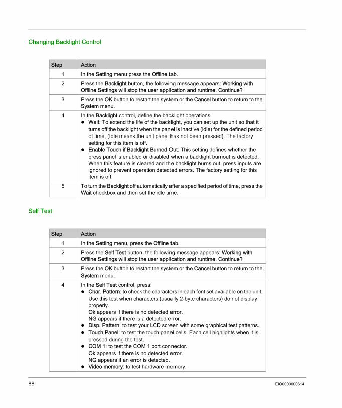
Changing Backlight Control
Self Test
Step Action1 In the Setting menu press the Offline tab.2 Press the Backlight button, the following message appears: Working with
Offline Settings will stop the user application and runtime. Continue? 3 Press the OK button to restart the system or the Cancel button to return to the
System menu.4 In the Backlight control, define the backlight operations.
Wait: To extend the life of the backlight, you can set up the unit so that it turns off the backlight when the panel is inactive (idle) for the defined period of time, (Idle means the unit panel has not been pressed). The factory setting for this item is off.
Enable Touch if Backlight Burned Out: This setting defines whether the press panel is enabled or disabled when a backlight burnout is detected. When this feature is cleared and the backlight burns out, press inputs are ignored to prevent operation detected errors. The factory setting for this item is off.
5 To turn the Backlight off automatically after a specified period of time, press the Wait checkbox and then set the idle time.
Step Action1 In the Setting menu, press the Offline tab.2 Press the Self Test button, the following message appears: Working with
Offline Settings will stop the user application and runtime. Continue? 3 Press the OK button to restart the system or the Cancel button to return to the
System menu.4 In the Self Test control, press:
Char. Pattern: to check the characters in each font set available on the unit. Use this test when characters (usually 2-byte characters) do not display properly.Ok appears if there is no detected error. NG appears if there is a detected error.
Disp. Pattern: to test your LCD screen with some graphical test patterns. Touch Panel: to test the touch panel cells. Each cell highlights when it is
pressed during the test. COM 1: to test the COM 1 port connector.
Ok appears if there is no detected error. NG appears if an error is detected.
Video memory: to test hardware memory.
88 EIO0000000614
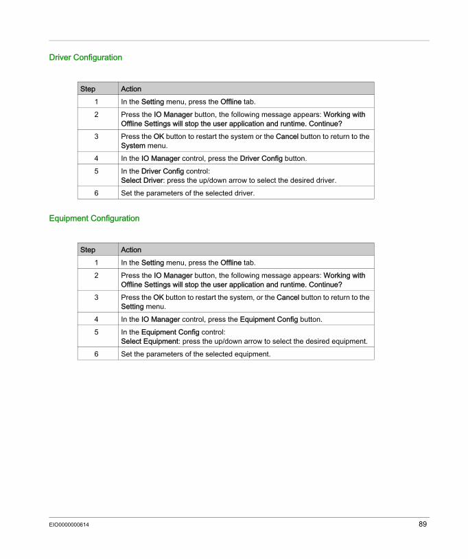
Driver Configuration
Equipment Configuration
Step Action1 In the Setting menu, press the Offline tab.2 Press the IO Manager button, the following message appears: Working with
Offline Settings will stop the user application and runtime. Continue? 3 Press the OK button to restart the system or the Cancel button to return to the
System menu.4 In the IO Manager control, press the Driver Config button.5 In the Driver Config control:
Select Driver: press the up/down arrow to select the desired driver.6 Set the parameters of the selected driver.
Step Action1 In the Setting menu, press the Offline tab.2 Press the IO Manager button, the following message appears: Working with
Offline Settings will stop the user application and runtime. Continue? 3 Press the OK button to restart the system, or the Cancel button to return to the
Setting menu.4 In the IO Manager control, press the Equipment Config button.5 In the Equipment Config control:
Select Equipment: press the up/down arrow to select the desired equipment.6 Set the parameters of the selected equipment.
EIO0000000614 89

Diagnostics Settings
IntroductionThe HMISTU655/855 units are equipped with a number of diagnostic features that can be used to check the systems and the interfaces for any problems.
DiagnosticsSee the Vijeo Designer online help for information on accessing the Diagnostics Settings menu.
VariablesUse the Variable menu to check that the application is running correctly. The following table describes how to get to the Variable menu:
Step Action1 In the Settings menu, press the Diagnostics tab.2 Press the Variable button.3 Select Equipment: press the up/down arrow to select the equipment whose
variables you want to test.4 In the Variable menu, press the Go Offscan button, the following message
appears: Warning: Entering the Variable Test screen pauses communication with all equipment. Continue?
5 Press the OK button to restart the system, or the Cancel button to return to the Variable menu.
6 If the Go Onscan is pressed, the test reads the value for each variable associated with the selected equipment. If any of the variables detects a problem, because of a detected error in the equipment or a time-out, the event log displays a message with the name of the variable.
7 After you complete testing variables from one equipment, you can continue testing variables for other equipment connected to the target machine.
8 Alternatively, you can test all equipment at once by selecting Test All in the Select Equipment drop-down list.
9 Press the Return button to return to the Diagnostics menu.
90 EIO0000000614
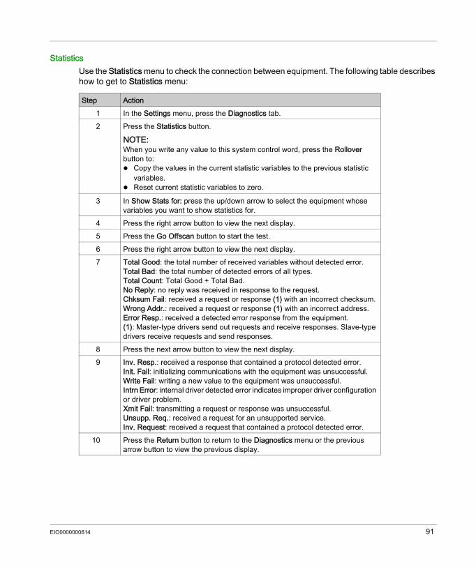
StatisticsUse the Statistics menu to check the connection between equipment. The following table describes how to get to Statistics menu:
Step Action1 In the Settings menu, press the Diagnostics tab.2 Press the Statistics button.
NOTE: When you write any value to this system control word, press the Rollover button to: Copy the values in the current statistic variables to the previous statistic
variables. Reset current statistic variables to zero.
3 In Show Stats for: press the up/down arrow to select the equipment whose variables you want to show statistics for.
4 Press the right arrow button to view the next display.5 Press the Go Offscan button to start the test.6 Press the right arrow button to view the next display.7 Total Good: the total number of received variables without detected error.
Total Bad: the total number of detected errors of all types.Total Count: Total Good + Total Bad.No Reply: no reply was received in response to the request.Chksum Fail: received a request or response (1) with an incorrect checksum.Wrong Addr.: received a request or response (1) with an incorrect address.Error Resp.: received a detected error response from the equipment.(1): Master-type drivers send out requests and receive responses. Slave-type drivers receive requests and send responses.
8 Press the next arrow button to view the next display.9 Inv. Resp.: received a response that contained a protocol detected error.
Init. Fail: initializing communications with the equipment was unsuccessful.Write Fail: writing a new value to the equipment was unsuccessful.Intrn Error: internal driver detected error indicates improper driver configuration or driver problem.Xmit Fail: transmitting a request or response was unsuccessful.Unsupp. Req.: received a request for an unsupported service.Inv. Request: received a request that contained a protocol detected error.
10 Press the Return button to return to the Diagnostics menu or the previous arrow button to view the previous display.
EIO0000000614 91

92 EIO0000000614
Harmony HMISTU655/855
EIO0000000614
Troubleshooting
Chapter 5Troubleshooting
OverviewThis chapter describes how to find and resolve detected problems with the HMISTU655/855 units.
What Is in This Chapter?This chapter contains the following topics:
Topic PageTroubleshooting Checklists 94Self Test List 97
EIO0000000614 93
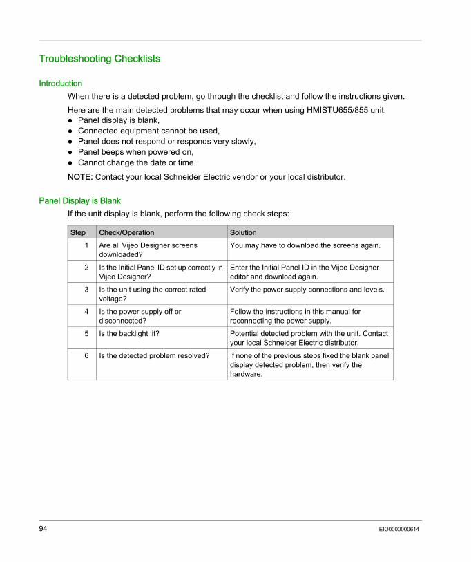
Troubleshooting Checklists
IntroductionWhen there is a detected problem, go through the checklist and follow the instructions given.Here are the main detected problems that may occur when using HMISTU655/855 unit. Panel display is blank, Connected equipment cannot be used, Panel does not respond or responds very slowly, Panel beeps when powered on, Cannot change the date or time.NOTE: Contact your local Schneider Electric vendor or your local distributor.
Panel Display is BlankIf the unit display is blank, perform the following check steps:
Step Check/Operation Solution1 Are all Vijeo Designer screens
downloaded?You may have to download the screens again.
2 Is the Initial Panel ID set up correctly in Vijeo Designer?
Enter the Initial Panel ID in the Vijeo Designer editor and download again.
3 Is the unit using the correct rated voltage?
Verify the power supply connections and levels.
4 Is the power supply off or disconnected?
Follow the instructions in this manual for reconnecting the power supply.
5 Is the backlight lit? Potential detected problem with the unit. Contact your local Schneider Electric distributor.
6 Is the detected problem resolved? If none of the previous steps fixed the blank panel display detected problem, then verify the hardware.
94 EIO0000000614
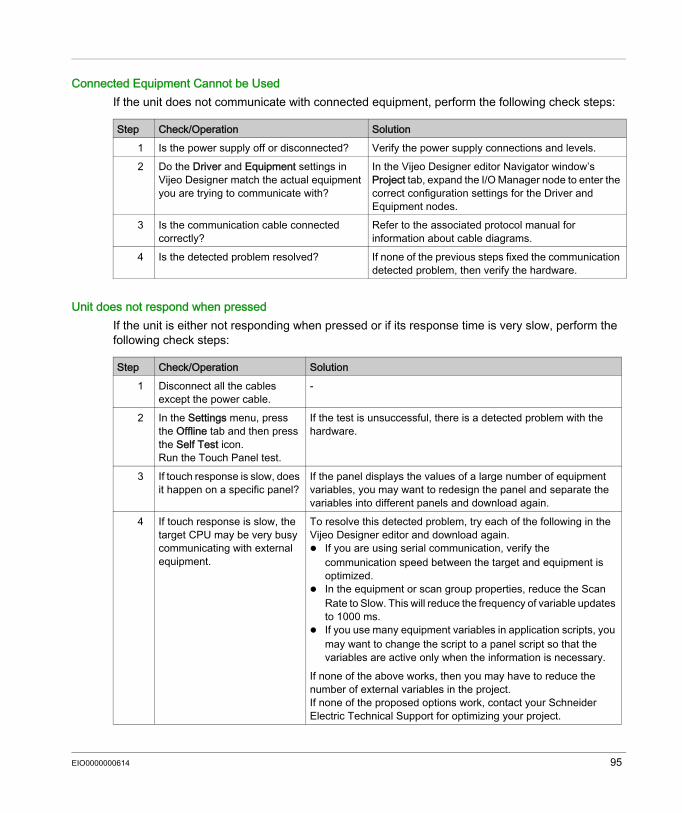
Connected Equipment Cannot be UsedIf the unit does not communicate with connected equipment, perform the following check steps:
Unit does not respond when pressedIf the unit is either not responding when pressed or if its response time is very slow, perform the following check steps:
Step Check/Operation Solution1 Is the power supply off or disconnected? Verify the power supply connections and levels.2 Do the Driver and Equipment settings in
Vijeo Designer match the actual equipment you are trying to communicate with?
In the Vijeo Designer editor Navigator window’s Project tab, expand the I/O Manager node to enter the correct configuration settings for the Driver and Equipment nodes.
3 Is the communication cable connected correctly?
Refer to the associated protocol manual for information about cable diagrams.
4 Is the detected problem resolved? If none of the previous steps fixed the communication detected problem, then verify the hardware.
Step Check/Operation Solution1 Disconnect all the cables
except the power cable.-
2 In the Settings menu, press the Offline tab and then press the Self Test icon. Run the Touch Panel test.
If the test is unsuccessful, there is a detected problem with the hardware.
3 If touch response is slow, does it happen on a specific panel?
If the panel displays the values of a large number of equipment variables, you may want to redesign the panel and separate the variables into different panels and download again.
4 If touch response is slow, the target CPU may be very busy communicating with external equipment.
To resolve this detected problem, try each of the following in the Vijeo Designer editor and download again. If you are using serial communication, verify the
communication speed between the target and equipment is optimized.
In the equipment or scan group properties, reduce the Scan Rate to Slow. This will reduce the frequency of variable updates to 1000 ms.
If you use many equipment variables in application scripts, you may want to change the script to a panel script so that the variables are active only when the information is necessary.
If none of the above works, then you may have to reduce the number of external variables in the project.If none of the proposed options work, contact your Schneider Electric Technical Support for optimizing your project.
EIO0000000614 95

Target beeps when powered ONA continuous beep from the target means that system files are corrupted. To resolve this detected problem, go to the Vijeo Designer Start menu and run Recovery on the target machine.
96 EIO0000000614
Self Test List
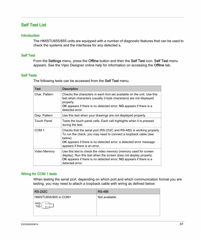
IntroductionThe HMISTU655/855 units are equipped with a number of diagnostic features that can be used to check the systems and the interfaces for any detected s.
Self TestFrom the Settings menu, press the Offline button and then the Self Test icon. Self Test menu appears. See the Vijeo Designer online help for information on accessing the Offline tab.
Self TestsThe following tests can be accessed from the Self Test menu.
Wiring for COM 1 testsWhen testing the serial port, depending on which port and which communication format you are testing, you may need to attach a loopback cable with wiring as defined below:
Test DescriptionChar. Pattern Checks the characters in each font set available on the unit. Use this
test when characters (usually 2-byte characters) are not displayed properly.OK appears if there is no detected error; NG appears if there is a detected error.
Disp. Pattern Use this test when your drawings are not displayed properly.Touch Panel Tests the touch panel cells. Each cell highlights when it is pressed
during the test.COM 1 Checks that the serial port (RS-232C and RS-485) is working properly.
To run the check, you may need to connect a loopback cable (see below).OK appears if there is no detected error; a detected error message appears if there is an error.
Video Memory Use this test to check the video memory (memory used for screen display). Run this test when the screen does not display properly.OK appears if there is no detected error; NG appears if there is a detected error.
RS-232C RS-485HMISTU655/855 in COM1 Not available.
EIO0000000614 97

98 EIO0000000614
Harmony HMISTU655/855
EIO0000000614
Maintenance
Chapter 6Maintenance
OverviewThis chapter explains how to maintain your HMISTU655/855 units.
What Is in This Chapter?This chapter contains the following topics:
Topic PageRegular Cleaning 100Periodic Check Points 102
EIO0000000614 99
Regular Cleaning
Cleaning the display
When the surface or the frame of the display gets dirty, soak a soft cloth in water with a neutral detergent, wring the cloth tightly and wipe the display.
Chemical SubstancesThe products in the following table can be used when cleaning the unit:
NOTICEEQUIPMENT DAMAGE Power off the unit before cleaning it. Do not use hard or pointed objects to operate the touch panel, since it can damage the panel
surface. Do not use paint thinner, organic solvents, or a strong acid compound to clean the unit.Failure to follow these instructions can result in equipment damage.
Kinds of fluid Company Product designation
Concentration Temperature °C (°F)
pH Value
Cleaning agents in the food and beverage industry
Ecolab Topmaxx 422 5 40 (104) 1% : pH=13Ecolab P3 Topax M 95 5 40 (104) 1% : pH=12.3Ecolab P3 Oxonia Active 3 40 (104)Ecolab P3 Topax 52 FR 5 40 (104) 1% : pH=2Ecolab P3 Topax 36 5 40 (104)Ecolab P3 Luboklar MH 0.7 40 (104)Johnson Diversey Divosan 2000 1 25 (77) 100% : pH=7Johnson Diversey Diverfoam
Septiplus5 25 (77) 3% : pH=8.3
Johnson Diversey Acifoam 5 25 (77) 1% : pH=2.2Johnson Diversey HD Plus Foam 5 25 (77) 1% : pH=12.9Johnson Diversey Oxofoam 5 25 (77) 1% : pH=12.7Johnson Diversey Endoroplus VE6 5 25 (77) 1% : pH=12.1Johnson Diversey Endoroforce VE2 5 25 (77) 1% : pH=12.5Johnson Diversey Endorocid VE10 5 25 (77) 1% : pH=2
100 EIO0000000614
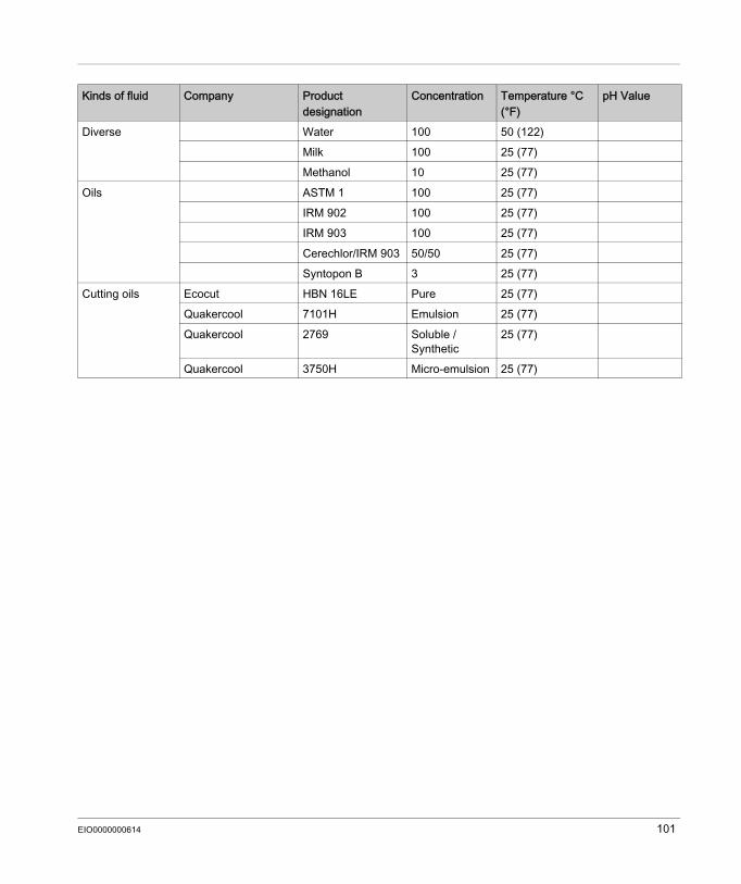
Diverse Water 100 50 (122)Milk 100 25 (77)Methanol 10 25 (77)
Oils ASTM 1 100 25 (77)IRM 902 100 25 (77)IRM 903 100 25 (77)Cerechlor/IRM 903 50/50 25 (77)Syntopon B 3 25 (77)
Cutting oils Ecocut HBN 16LE Pure 25 (77)Quakercool 7101H Emulsion 25 (77)Quakercool 2769 Soluble /
Synthetic25 (77)
Quakercool 3750H Micro-emulsion 25 (77)
Kinds of fluid Company Product designation
Concentration Temperature °C (°F)
pH Value
EIO0000000614 101
Periodic Check Points
Operation EnvironmentRefer to the Environmental Specifications (see page 30).
Electrical SpecificationsThe input voltage must be within 20.4 to 28.8 Vdc.
Related Items Are all power cords and cables connected properly? Are there any loose cables? Are all mounting brackets holding the unit securely? Are there scratches or traces of dirt on the installation gasket?
102 EIO0000000614
Harmony HMISTU655/855IndexEIO0000000614
Index
Symbols Peripherals
Edit Mode, 26
Aaccessories, 16
CCertifications and Standards, 24Connecting the Power Cord, 58Connecting the Power Supply, 61
DDiagnostics Settings, 90
EEdit Mode Peripherals, 26Ethernet
Cable connector, 77
GGrounding, 63
IInstallation
Procedures, 51
MMaintenance
Check points, 102Cleaning, 100
EIO0000000614
PPart number
HMISTU655, 12HMISTU655W, 12HMISTU855, 12HMISTU855W, 12
Parts Identification and Functions, 20Power plug, 58
SSelf Test, 97Settings
menu, 82Specifications
COM, 38COM1, 37, 38Display, 33General, 30Interfaces, 37Memory, 37, 37USB, 37, 37
System Settings, 83
TTroubleshooting, 94
UUSB
Data Transfer Cable, 67Mini-B, 74Port, 66Standard A, 69
103

Index
104 EIO0000000614