Embed Size (px)
Citation preview
MPLAB Harmony ConfiguratorUser's Guide
MPLAB Harmony Integrated Software Framework
© 2013-2017 Microchip Technology Inc. All rights reserved.
MPLAB Harmony Configurator User's Guide This section provides user information on using the MHC.
MPLAB Harmony Configurator User's Guide
© 2013-2017 Microchip Technology Inc. MPLAB Harmony v2.05 2
Installing MHC
This topic provides information on installing the MHC plug-in.
Description
Installing the MHC Plug-in
1. Start MPLAB X IDE and select Tools > Plugins.
2. Select the Downloaded tab and click Add Plugins...
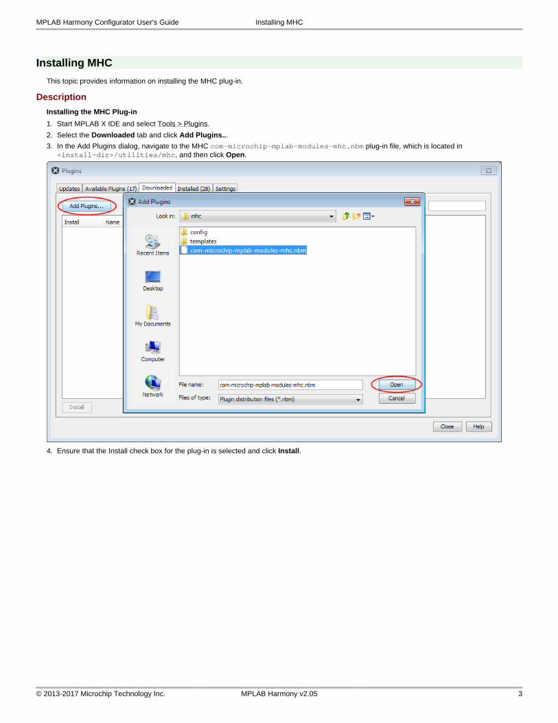
3. In the Add Plugins dialog, navigate to the MHC com-microchip-mplab-modules-mhc.nbm plug-in file, which is located in <install-dir>/utilities/mhc, and then click Open.
4. Ensure that the Install check box for the plug-in is selected and click Install.
MPLAB Harmony Configurator User's Guide Installing MHC
© 2013-2017 Microchip Technology Inc. MPLAB Harmony v2.05 3
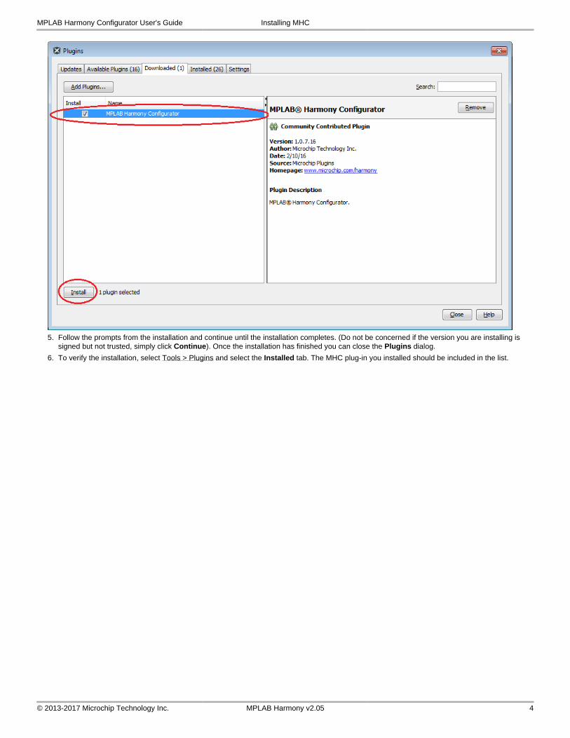
5. Follow the prompts from the installation and continue until the installation completes. (Do not be concerned if the version you are installing is signed but not trusted, simply click Continue). Once the installation has finished you can close the Plugins dialog.
6. To verify the installation, select Tools > Plugins and select the Installed tab. The MHC plug-in you installed should be included in the list.
MPLAB Harmony Configurator User's Guide Installing MHC
© 2013-2017 Microchip Technology Inc. MPLAB Harmony v2.05 4
MPLAB Harmony Configurator Interface
This section describes the MHC interface.
Description
This section provides a basic overview of the MHC user interface. For detailed information on using MHC to create a MPLAB Harmony application, refer to Using MHC to Create a New Application. Most of the figures shown in this section are from screen captures of MPLAB with the Aria Quickstart project loaded. You can find this project in the MPLAB Harmony application folder .\apps\gfx\aria_quickstart\firmware\aria_quickstart.X. Load this project and follow along.
Quick Review of MPLAB Windows
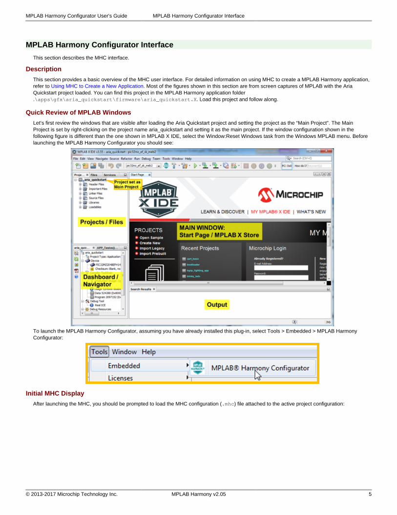
Let’s first review the windows that are visible after loading the Aria Quickstart project and setting the project as the “Main Project”. The Main Project is set by right-clicking on the project name aria_quickstart and setting it as the main project. If the window configuration shown in the following figure is different than the one shown in MPLAB X IDE, select the Window:Reset Windows task from the Windows MPLAB menu. Before launching the MPLAB Harmony Configurator you should see:
To launch the MPLAB Harmony Configurator, assuming you have already installed this plug-in, select Tools > Embedded > MPLAB Harmony Configurator:
Initial MHC Display
After launching the MHC, you should be prompted to load the MHC configuration (.mhc) file attached to the active project configuration:
MPLAB Harmony Configurator User's Guide MPLAB Harmony Configurator Interface
© 2013-2017 Microchip Technology Inc. MPLAB Harmony v2.05 5
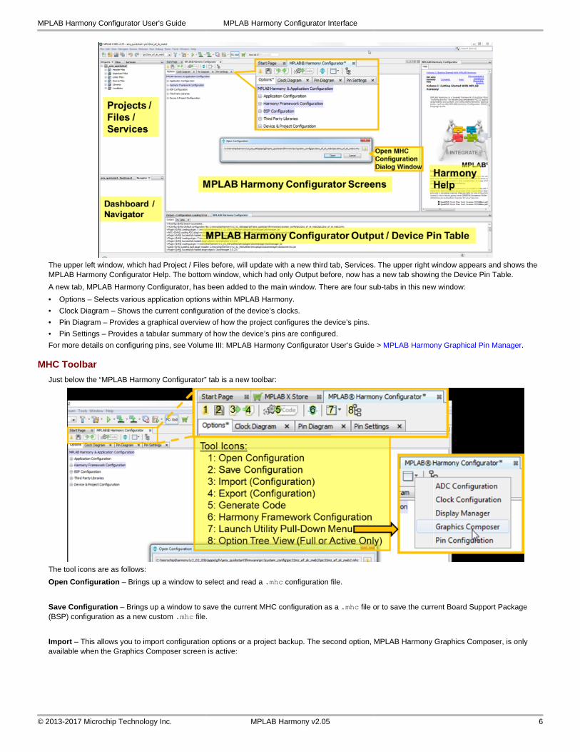
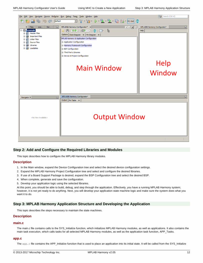
The upper left window, which had Project / Files before, will update with a new third tab, Services. The upper right window appears and shows the MPLAB Harmony Configurator Help. The bottom window, which had only Output before, now has a new tab showing the Device Pin Table.
A new tab, MPLAB Harmony Configurator, has been added to the main window. There are four sub-tabs in this new window:
• Options – Selects various application options within MPLAB Harmony.
• Clock Diagram – Shows the current configuration of the device’s clocks.
• Pin Diagram – Provides a graphical overview of how the project configures the device’s pins.
• Pin Settings – Provides a tabular summary of how the device’s pins are configured.
For more details on configuring pins, see Volume III: MPLAB Harmony Configurator User’s Guide > MPLAB Harmony Graphical Pin Manager.
MHC Toolbar
Just below the “MPLAB Harmony Configurator” tab is a new toolbar:
The tool icons are as follows:
Open Configuration – Brings up a window to select and read a .mhc configuration file.
Save Configuration – Brings up a window to save the current MHC configuration as a .mhc file or to save the current Board Support Package (BSP) configuration as a new custom .mhc file.
Import – This allows you to import configuration options or a project backup. The second option, MPLAB Harmony Graphics Composer, is only available when the Graphics Composer screen is active:
MPLAB Harmony Configurator User's Guide MPLAB Harmony Configurator Interface
© 2013-2017 Microchip Technology Inc. MPLAB Harmony v2.05 6
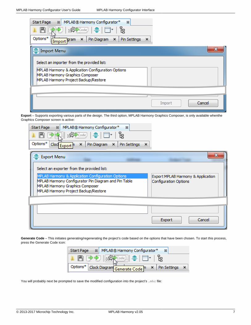
Export – Supports exporting various parts of the design. The third option, MPLAB Harmony Graphics Composer, is only available whenthe Graphics Composer screen is active:
Generate Code – This initiates generating/regenerating the project’s code based on the options that have been chosen. To start this process, press the Generate Code icon:
You will probably next be prompted to save the modified configuration into the project’s .mhc file:
MPLAB Harmony Configurator User's Guide MPLAB Harmony Configurator Interface
© 2013-2017 Microchip Technology Inc. MPLAB Harmony v2.05 7
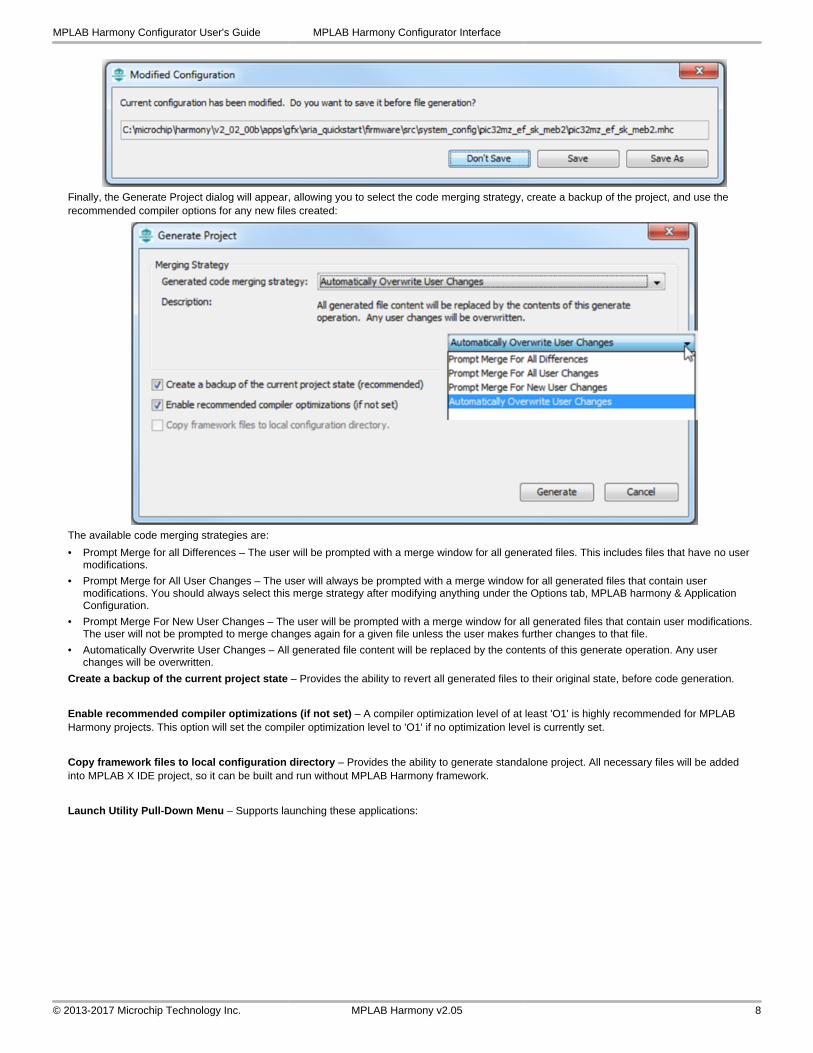
Finally, the Generate Project dialog will appear, allowing you to select the code merging strategy, create a backup of the project, and use the recommended compiler options for any new files created:
The available code merging strategies are:
• Prompt Merge for all Differences – The user will be prompted with a merge window for all generated files. This includes files that have no user modifications.
• Prompt Merge for All User Changes – The user will always be prompted with a merge window for all generated files that contain user modifications. You should always select this merge strategy after modifying anything under the Options tab, MPLAB harmony & Application Configuration.
• Prompt Merge For New User Changes – The user will be prompted with a merge window for all generated files that contain user modifications. The user will not be prompted to merge changes again for a given file unless the user makes further changes to that file.
• Automatically Overwrite User Changes – All generated file content will be replaced by the contents of this generate operation. Any user changes will be overwritten.
Create a backup of the current project state – Provides the ability to revert all generated files to their original state, before code generation.
Enable recommended compiler optimizations (if not set) – A compiler optimization level of at least 'O1' is highly recommended for MPLAB Harmony projects. This option will set the compiler optimization level to 'O1' if no optimization level is currently set.
Copy framework files to local configuration directory – Provides the ability to generate standalone project. All necessary files will be added into MPLAB X IDE project, so it can be built and run without MPLAB Harmony framework.
Launch Utility Pull-Down Menu – Supports launching these applications:
MPLAB Harmony Configurator User's Guide MPLAB Harmony Configurator Interface
© 2013-2017 Microchip Technology Inc. MPLAB Harmony v2.05 8
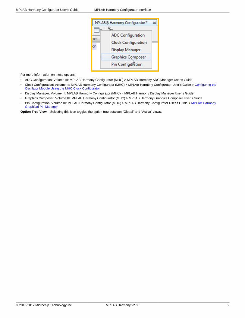
For more information on these options:
• ADC Configuration: Volume III: MPLAB Harmony Configurator (MHC) > MPLAB Harmony ADC Manager User’s Guide
• Clock Configuration: Volume III: MPLAB Harmony Configurator (MHC) > MPLAB Harmony Configurator User’s Guide > Configuring the Oscillator Module Using the MHC Clock Configurator
• Display Manager: Volume III: MPLAB Harmony Configurator (MHC) > MPLAB Harmony Display Manager User’s Guide
• Graphics Composer: Volume III: MPLAB Harmony Configurator (MHC) > MPLAB Harmony Graphics Composer User’s Guide
• Pin Configuration: Volume III: MPLAB Harmony Configurator (MHC) > MPLAB Harmony Configurator User’s Guide > MPLAB Harmony Graphical Pin Manager
Option Tree View – Selecting this icon toggles the option tree between “Global” and “Active” views.
MPLAB Harmony Configurator User's Guide MPLAB Harmony Configurator Interface
© 2013-2017 Microchip Technology Inc. MPLAB Harmony v2.05 9
Using MHC to Create a New Application
Provides information on creating a new MHC project.
Introduction
This section provides an introduction to creating your own MPLAB Harmony applications using the MPLAB Harmony Configurator (MHC).
Description
MPLAB Harmony provides a MPLAB Harmony Configurator (MHC) MPLAB X IDE plug-in that can be installed in MPLAB X IDE to help you create your own MPLAB Harmony applications.
To create a new MPLAB Harmony application with MHC, follow these three steps:
• Step 1: Create the New Harmony Project
• Step 2: Add and Configure Required Libraries/Modules
• Step 3: MPLAB Harmony Application Structure and Developing the Application
Note:If you are a Microchip Libraries for Applications (MLA) user, and will be porting your application from the MLA TCP/IP, File System, USB Device, Graphics, or peripheral libraries to the MPLAB Harmony equivalents, refer to Porting to MPLAB Harmony for more information.
Prerequisites
This topic describes the prerequisites for creating your own MPLAB Harmony applications using MHC.
Description
This tutorial assumes that you have already completed these steps before you start:
1. Installed the MPLAB X IDE (http://www.microchip.com/mplabx).
2. Installed MPLAB Harmony (http://www.microchip.com/harmony).
3. Installed the MPLAB XC32 C/C++ Compiler (http://www.microchip.com/xc32).
4. Set up a working PIC32 development platform (http://www.microchip.com/32bit).
You can download the MPLAB X IDE, MPLAB Harmony and the MPLAB XC32 C/C++ Compiler from the links provided. If you do not already have a PIC32 development platform, you can learn more about the PIC32 family and determine which hardware platform best meets your development needs by visiting the 32-bit website listed previously.
This tutorial also assumes that you have some familiarity with the MPLAB X IDE, embedded C-language programming and PIC32 microcontrollers. If you are unsure how to complete some of the steps in this tutorial, please refer to the documentation for the item on which you have questions. You may also seek assistance from your peers on the Microchip discussion forums (http://www.microchip.com/forums) or from the Microchip support staff (www.microchip.com/support).
Once you have everything installed, connected, and up and running you are ready to begin creating your own MPLAB Harmony applications.
Step 1: Create the New Project
To create a new MPLAB Harmony project, you first need to create a new MPLAB X IDE project and the basic set of source code files and functions that are necessary for a properly formed MPLAB Harmony application.
Description
To create a new MHC project:
1. Select File > New Project or click the New Project icon in MPLAB X IDE.
2. In Categories, select Microchip Embedded and in Projects select MPLAB Harmony Project from the list of available project templates, and then click Next to launch the Microchip Harmony Configurator Project Wizard.
MPLAB Harmony Configurator User's Guide Using MHC to Create a New Application Step 1: Create the New Project
© 2013-2017 Microchip Technology Inc. MPLAB Harmony v2.05 10
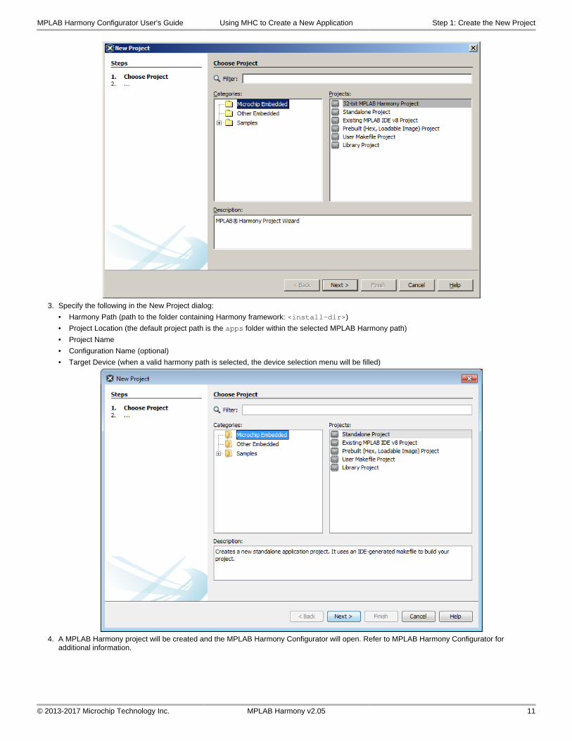
3. Specify the following in the New Project dialog:
• Harmony Path (path to the folder containing Harmony framework: <install-dir>)
• Project Location (the default project path is the apps folder within the selected MPLAB Harmony path)
• Project Name
• Configuration Name (optional)
• Target Device (when a valid harmony path is selected, the device selection menu will be filled)
4. A MPLAB Harmony project will be created and the MPLAB Harmony Configurator will open. Refer to MPLAB Harmony Configurator for additional information.
MPLAB Harmony Configurator User's Guide Using MHC to Create a New Application Step 1: Create the New Project
© 2013-2017 Microchip Technology Inc. MPLAB Harmony v2.05 11
Step 2: Add and Configure the Required Libraries and Modules
This topic describes how to configure the MPLAB Harmony library modules.
Description
1. In the Main window, expand the Device Configuration tree and select the desired device configuration settings.
2. Expand the MPLAB Harmony Project Configuration tree and select and configure the desired libraries.
3. If use of a Board Support Package is desired, expand the BSP Configuration tree and select the desired BSP.
4. When complete, generate and save the configuration.
5. Develop your application logic using the selected libraries.
At this point, you should be able to build, debug, and step through the application. Effectively, you have a running MPLAB Harmony system; however, it is not yet ready to do anything. Next, you will develop your application state machine logic and make sure the system does what you want it to do.
Step 3: MPLAB Harmony Application Structure and Developing the Application
This topic describes the steps necessary to maintain the state machines.
Description
main.c
The main.c file contains calls to the SYS_Initialize function, which initializes MPLAB Harmony modules, as well as applications. It also contains the main task execution, which calls tasks for all selected MPLAB Harmony modules, as well as the application task function, APP_Tasks.
app.c
The app.c file contains the APP_Initialize function that is used to place an application into its initial state. It will be called from the SYS_Initialize
MPLAB Harmony Configurator User's Guide Using MHC to Create a New Application Step 3: MPLAB Harmony Application Structure
© 2013-2017 Microchip Technology Inc. MPLAB Harmony v2.05 12
function. The APP_Task function, which is also contained in the app.c file, implements the application state machine logic. Add application code to this task as desired.
Refer to the example applications located in the <install-dir>/apps/ folder within your MPLAB Harmony installation for example applications for various MPLAB Harmony modules. Related documentation is available in the Applications Help > Examples section.
MPLAB Harmony Configurator User's Guide Using MHC to Create a New Application Step 3: MPLAB Harmony Application Structure
© 2013-2017 Microchip Technology Inc. MPLAB Harmony v2.05 13
Porting a Legacy PLIB to MPLAB Harmony
Provides an example on how to port a legacy (i.e., prior to MPLAB Harmony) USART Peripheral Library (PLIB) demonstration application to a MPLAB Harmony application using the MPLAB Harmony Configurator (MHC).
Description
A detailed procedure for porting the legacy UART PLIB Interrupt demonstration application (<compiler-install-dir>/examples/plib_examples/uart/uart_interrupt) to MPLAB Harmony is provided in the Framework Help > Peripheral Library Help > Peripheral Library Porting Example .
In this example, the following assumptions are made:
• The PIC32MX795F512L device will be used; however, the process described in this section is applicable for other PIC32 devices with appropriate changes
• The Explorer 16 Development Board is the hardware used in this example
• For the v1.33 MPLAB XC32 C/C++ Compiler, the examples folder is not present. To view the legacy USART PLIB example, refer to v1.31 or earlier of the MPLAB XC32 C/C++ compiler.
MPLAB Harmony Configurator User's Guide Porting a Legacy PLIB to MPLAB Harmony
© 2013-2017 Microchip Technology Inc. MPLAB Harmony v2.05 14
Configuring the Oscillator Module Using the MHC Clock Configurator
Provides information configuring the Oscillator module using the MHC Clock configurator
Description
The MHC Clock Configurator is a component of the MPLAB Harmony Configurator (MHC) MPLAB X IDE plug-in. Its function is to provide a graphical user interface to configure the Oscillator module.
While simulating the normal operation of the Oscillator module, the MHC Clock Configurator contains interactive controls, dynamic output, and visual warnings to help guide the user in establishing the desired system clock configuration.
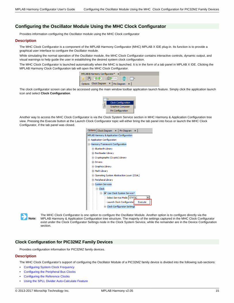
The MHC Clock Configurator is launched automatically when the MHC is launched. It is in the form of a tab panel in MPLAB X IDE. Clicking the MPLAB Harmony Clock Configuration tab will open the MHC Clock Configurator.
The clock configurator screen can also be accessed using the main window toolbar application launch feature. Simply click the application launch icon and select Clock Configuration.
Another way to access the MHC Clock Configurator is via the Clock System Service section in MHC Harmony & Application Configuration tree view. Pressing the Execute button at the Launch Clock Configurator topic will either bring the tab panel into focus or launch the MHC Clock Configurator, if the tab panel was closed.
Note:The MHC Clock Configurator is one option to configure the Oscillator Module. Another option is to configure directly via the MPLAB Harmony & Application Configuration tree structure. The majority of the settings captured in the MHC Clock Configurator exist under the Clock Configurator Settings node in the Clock System Service, while the remainder are in the Device Configuration section.
Clock Configuration for PIC32MZ Family Devices
Provides configuration information for PIC32MZ family devices.
Description
The MHC Clock Configurator’s support of configuring the Oscillator Module of a PIC32MZ family device is divided into the following sub-sections:
• Configuring System Clock Frequency
• Configuring the Peripheral Bus Clocks
• Configuring the Reference Clocks
• Using the SPLL Divider Auto-Calculate Feature
MPLAB Harmony Configurator User's Guide Configuring the Oscillator Module Using the MHC Clock Configuration for PIC32MZ Family Devices
© 2013-2017 Microchip Technology Inc. MPLAB Harmony v2.05 15
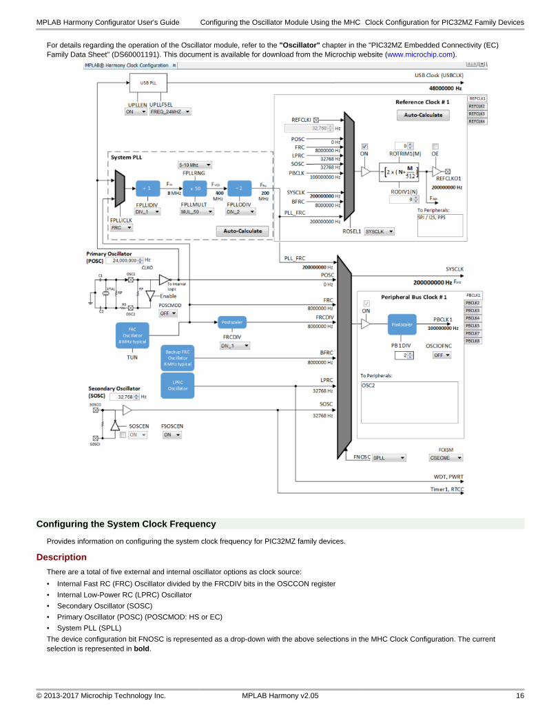
For details regarding the operation of the Oscillator module, refer to the "Oscillator" chapter in the "PIC32MZ Embedded Connectivity (EC) Family Data Sheet" (DS60001191). This document is available for download from the Microchip website (www.microchip.com).
Configuring the System Clock Frequency
Provides information on configuring the system clock frequency for PIC32MZ family devices.
Description
There are a total of five external and internal oscillator options as clock source:
• Internal Fast RC (FRC) Oscillator divided by the FRCDIV bits in the OSCCON register
• Internal Low-Power RC (LPRC) Oscillator
• Secondary Oscillator (SOSC)
• Primary Oscillator (POSC) (POSCMOD: HS or EC)
• System PLL (SPLL)
The device configuration bit FNOSC is represented as a drop-down with the above selections in the MHC Clock Configuration. The current selection is represented in bold.
MPLAB Harmony Configurator User's Guide Configuring the Oscillator Module Using the MHC Clock Configuration for PIC32MZ Family Devices
© 2013-2017 Microchip Technology Inc. MPLAB Harmony v2.05 16
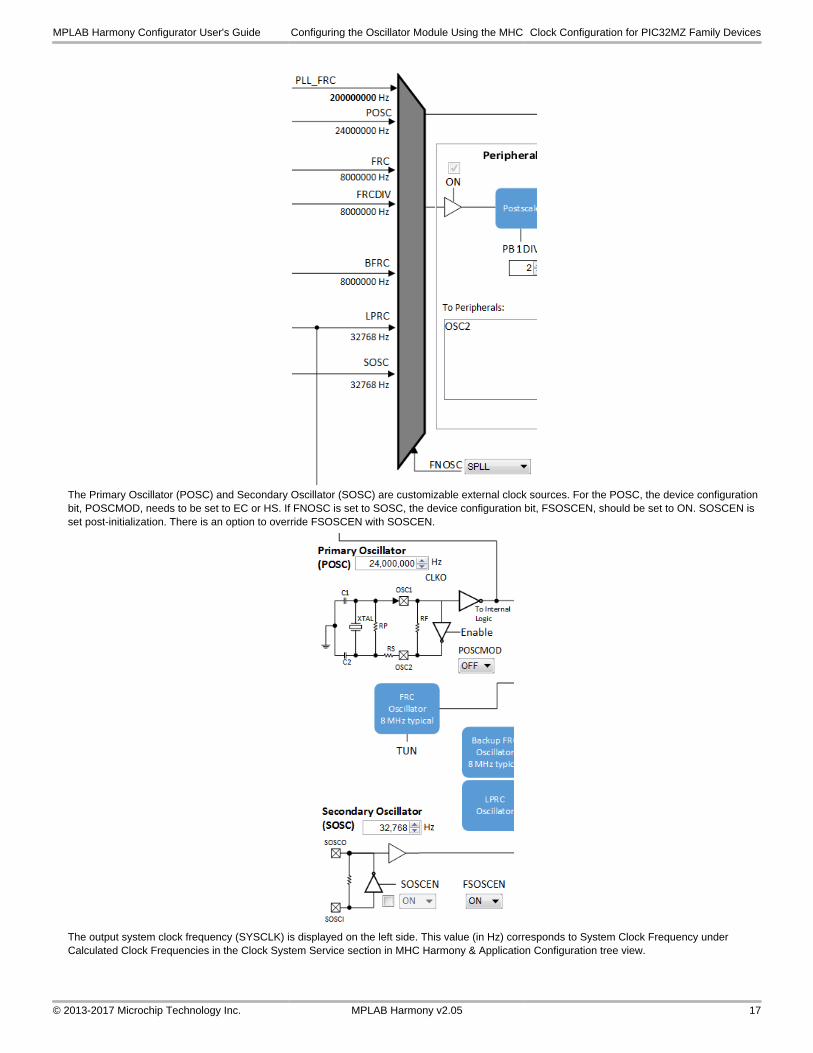
The Primary Oscillator (POSC) and Secondary Oscillator (SOSC) are customizable external clock sources. For the POSC, the device configuration bit, POSCMOD, needs to be set to EC or HS. If FNOSC is set to SOSC, the device configuration bit, FSOSCEN, should be set to ON. SOSCEN is set post-initialization. There is an option to override FSOSCEN with SOSCEN.
The output system clock frequency (SYSCLK) is displayed on the left side. This value (in Hz) corresponds to System Clock Frequency under Calculated Clock Frequencies in the Clock System Service section in MHC Harmony & Application Configuration tree view.
MPLAB Harmony Configurator User's Guide Configuring the Oscillator Module Using the MHC Clock Configuration for PIC32MZ Family Devices
© 2013-2017 Microchip Technology Inc. MPLAB Harmony v2.05 17
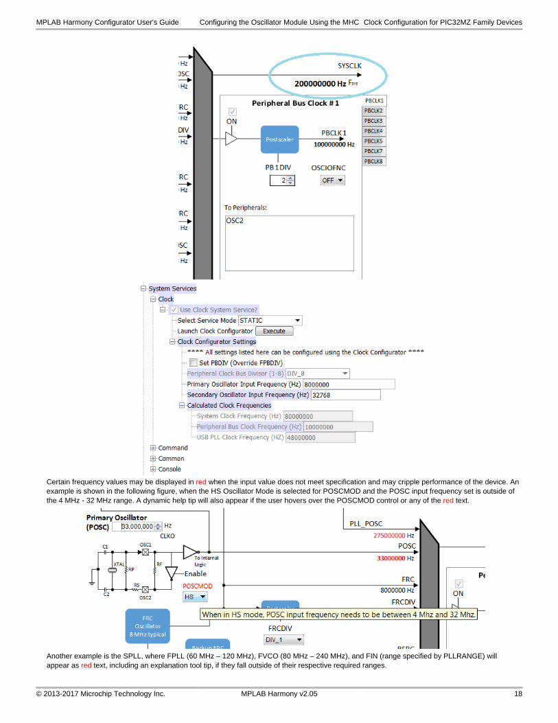
Certain frequency values may be displayed in red when the input value does not meet specification and may cripple performance of the device. An example is shown in the following figure, when the HS Oscillator Mode is selected for POSCMOD and the POSC input frequency set is outside of the 4 MHz - 32 MHz range. A dynamic help tip will also appear if the user hovers over the POSCMOD control or any of the red text.
Another example is the SPLL, where FPLL (60 MHz – 120 MHz), FVCO (80 MHz – 240 MHz), and FIN (range specified by PLLRANGE) will appear as red text, including an explanation tool tip, if they fall outside of their respective required ranges.
MPLAB Harmony Configurator User's Guide Configuring the Oscillator Module Using the MHC Clock Configuration for PIC32MZ Family Devices
© 2013-2017 Microchip Technology Inc. MPLAB Harmony v2.05 18
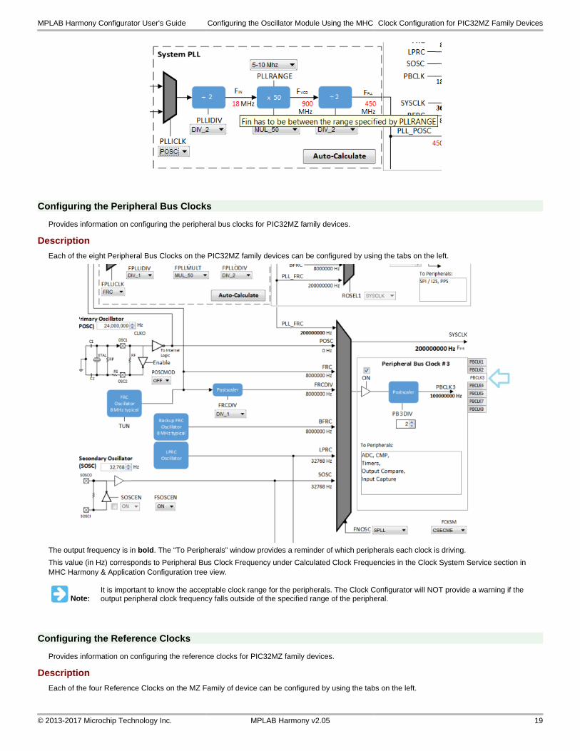
Configuring the Peripheral Bus Clocks
Provides information on configuring the peripheral bus clocks for PIC32MZ family devices.
Description
Each of the eight Peripheral Bus Clocks on the PIC32MZ family devices can be configured by using the tabs on the left.
The output frequency is in bold. The “To Peripherals” window provides a reminder of which peripherals each clock is driving.
This value (in Hz) corresponds to Peripheral Bus Clock Frequency under Calculated Clock Frequencies in the Clock System Service section in MHC Harmony & Application Configuration tree view.
Note:It is important to know the acceptable clock range for the peripherals. The Clock Configurator will NOT provide a warning if the output peripheral clock frequency falls outside of the specified range of the peripheral.
Configuring the Reference Clocks
Provides information on configuring the reference clocks for PIC32MZ family devices.
Description
Each of the four Reference Clocks on the MZ Family of device can be configured by using the tabs on the left.
MPLAB Harmony Configurator User's Guide Configuring the Oscillator Module Using the MHC Clock Configuration for PIC32MZ Family Devices
© 2013-2017 Microchip Technology Inc. MPLAB Harmony v2.05 19
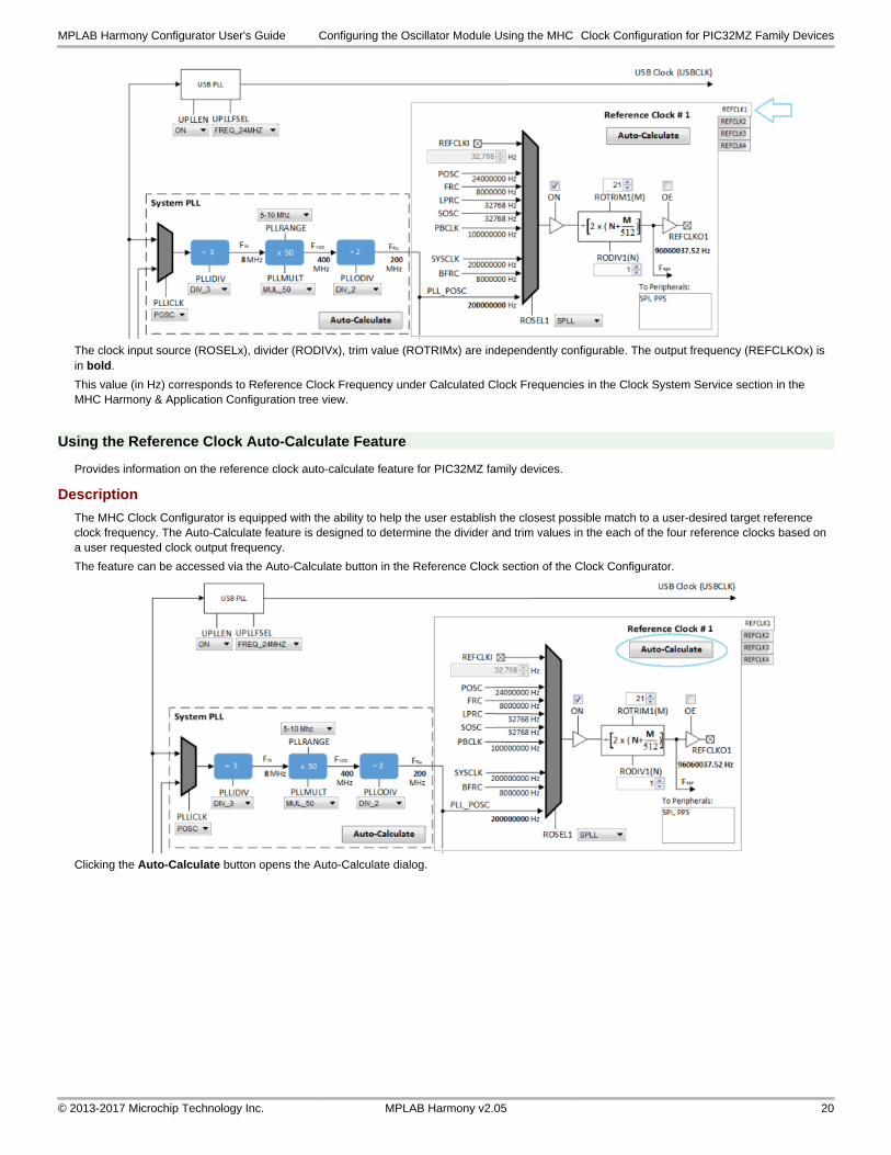
The clock input source (ROSELx), divider (RODIVx), trim value (ROTRIMx) are independently configurable. The output frequency (REFCLKOx) is in bold.
This value (in Hz) corresponds to Reference Clock Frequency under Calculated Clock Frequencies in the Clock System Service section in the MHC Harmony & Application Configuration tree view.
Using the Reference Clock Auto-Calculate Feature
Provides information on the reference clock auto-calculate feature for PIC32MZ family devices.
Description
The MHC Clock Configurator is equipped with the ability to help the user establish the closest possible match to a user-desired target reference clock frequency. The Auto-Calculate feature is designed to determine the divider and trim values in the each of the four reference clocks based on a user requested clock output frequency.
The feature can be accessed via the Auto-Calculate button in the Reference Clock section of the Clock Configurator.
Clicking the Auto-Calculate button opens the Auto-Calculate dialog.
MPLAB Harmony Configurator User's Guide Configuring the Oscillator Module Using the MHC Clock Configuration for PIC32MZ Family Devices
© 2013-2017 Microchip Technology Inc. MPLAB Harmony v2.05 20
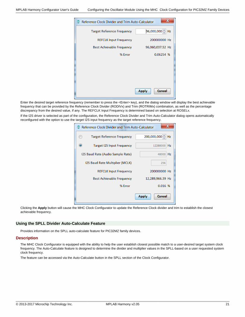
Enter the desired target reference frequency (remember to press the <Enter> key), and the dialog window will display the best achievable frequency that can be provided by the Reference Clock Divider (RODIVx) and Trim (ROTRIMx) combination, as well as the percentage discrepancy from the desired value, if any. The REFCLK Input Frequency is determined based on selection at ROSELx.
If the I2S driver is selected as part of the configuration, the Reference Clock Divider and Trim Auto-Calculator dialog opens automatically reconfigured with the option to use the target I2S input frequency as the target reference frequency.
Clicking the Apply button will cause the MHC Clock Configurator to update the Reference Clock divider and trim to establish the closest achievable frequency.
Using the SPLL Divider Auto-Calculate Feature
Provides information on the SPLL auto-calculate feature for PIC32MZ family devices.
Description
The MHC Clock Configurator is equipped with the ability to help the user establish closest possible match to a user-desired target system clock frequency. The Auto-Calculate feature is designed to determine the divider and multiplier values in the SPLL-based on a user requested system clock frequency.
The feature can be accessed via the Auto-Calculate button in the SPLL section of the Clock Configurator.
MPLAB Harmony Configurator User's Guide Configuring the Oscillator Module Using the MHC Clock Configuration for PIC32MZ Family Devices
© 2013-2017 Microchip Technology Inc. MPLAB Harmony v2.05 21
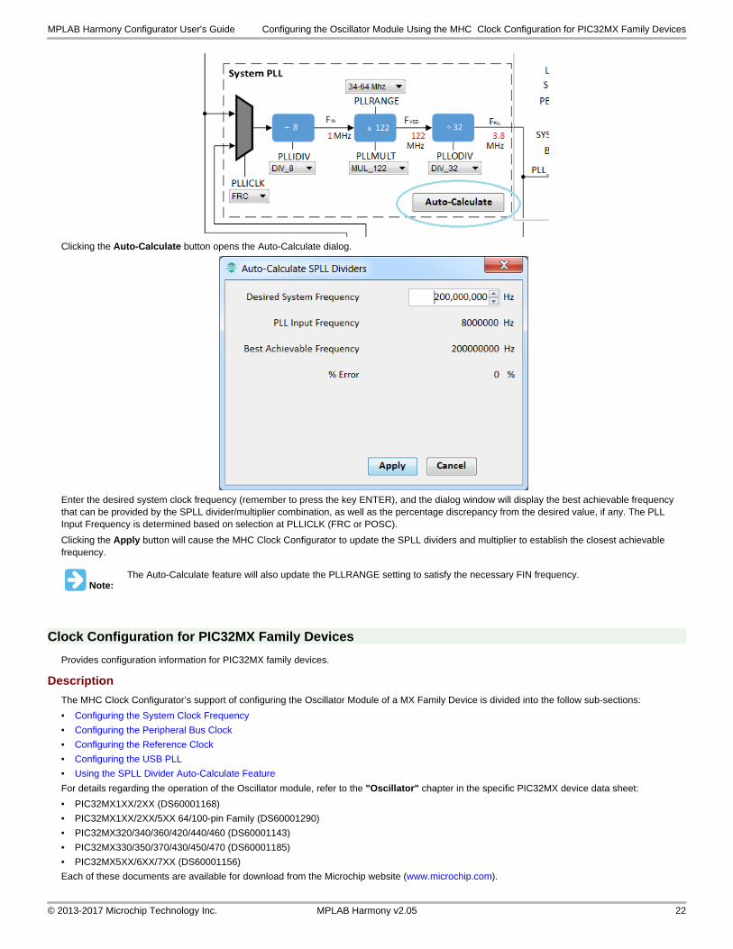
Clicking the Auto-Calculate button opens the Auto-Calculate dialog.
Enter the desired system clock frequency (remember to press the key ENTER), and the dialog window will display the best achievable frequency that can be provided by the SPLL divider/multiplier combination, as well as the percentage discrepancy from the desired value, if any. The PLL Input Frequency is determined based on selection at PLLICLK (FRC or POSC).
Clicking the Apply button will cause the MHC Clock Configurator to update the SPLL dividers and multiplier to establish the closest achievable frequency.
Note:The Auto-Calculate feature will also update the PLLRANGE setting to satisfy the necessary FIN frequency.
Clock Configuration for PIC32MX Family Devices
Provides configuration information for PIC32MX family devices.
Description
The MHC Clock Configurator’s support of configuring the Oscillator Module of a MX Family Device is divided into the follow sub-sections:
• Configuring the System Clock Frequency
• Configuring the Peripheral Bus Clock
• Configuring the Reference Clock
• Configuring the USB PLL
• Using the SPLL Divider Auto-Calculate Feature
For details regarding the operation of the Oscillator module, refer to the "Oscillator" chapter in the specific PIC32MX device data sheet:
• PIC32MX1XX/2XX (DS60001168)
• PIC32MX1XX/2XX/5XX 64/100-pin Family (DS60001290)
• PIC32MX320/340/360/420/440/460 (DS60001143)
• PIC32MX330/350/370/430/450/470 (DS60001185)
• PIC32MX5XX/6XX/7XX (DS60001156)
Each of these documents are available for download from the Microchip website (www.microchip.com).
MPLAB Harmony Configurator User's Guide Configuring the Oscillator Module Using the MHC Clock Configuration for PIC32MX Family Devices
© 2013-2017 Microchip Technology Inc. MPLAB Harmony v2.05 22
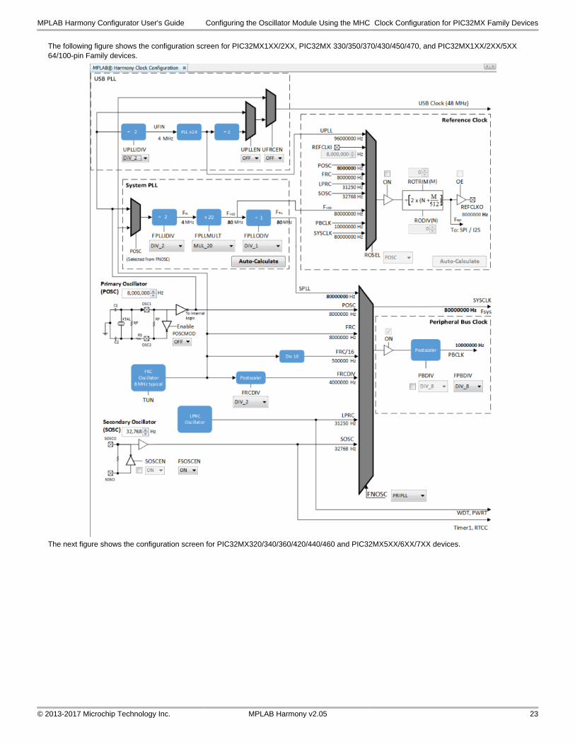
The following figure shows the configuration screen for PIC32MX1XX/2XX, PIC32MX 330/350/370/430/450/470, and PIC32MX1XX/2XX/5XX 64/100-pin Family devices.
The next figure shows the configuration screen for PIC32MX320/340/360/420/440/460 and PIC32MX5XX/6XX/7XX devices.
MPLAB Harmony Configurator User's Guide Configuring the Oscillator Module Using the MHC Clock Configuration for PIC32MX Family Devices
© 2013-2017 Microchip Technology Inc. MPLAB Harmony v2.05 23
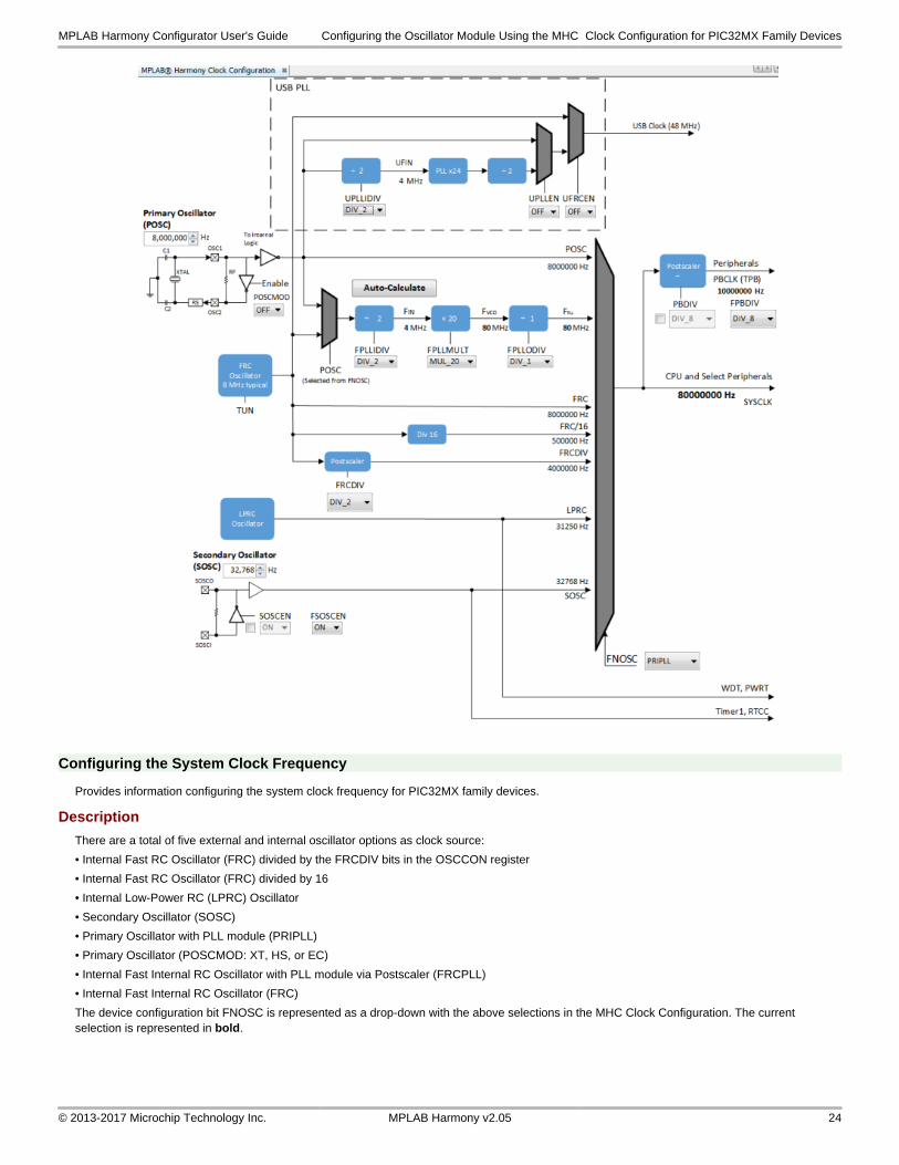
Configuring the System Clock Frequency
Provides information configuring the system clock frequency for PIC32MX family devices.
Description
There are a total of five external and internal oscillator options as clock source:
• Internal Fast RC Oscillator (FRC) divided by the FRCDIV bits in the OSCCON register
• Internal Fast RC Oscillator (FRC) divided by 16
• Internal Low-Power RC (LPRC) Oscillator
• Secondary Oscillator (SOSC)
• Primary Oscillator with PLL module (PRIPLL)
• Primary Oscillator (POSCMOD: XT, HS, or EC)
• Internal Fast Internal RC Oscillator with PLL module via Postscaler (FRCPLL)
• Internal Fast Internal RC Oscillator (FRC)
The device configuration bit FNOSC is represented as a drop-down with the above selections in the MHC Clock Configuration. The current selection is represented in bold.
MPLAB Harmony Configurator User's Guide Configuring the Oscillator Module Using the MHC Clock Configuration for PIC32MX Family Devices
© 2013-2017 Microchip Technology Inc. MPLAB Harmony v2.05 24
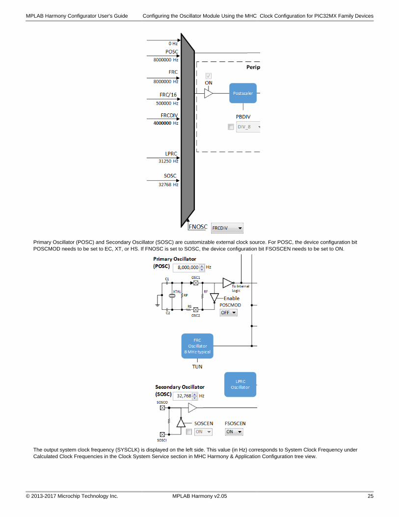
Primary Oscillator (POSC) and Secondary Oscillator (SOSC) are customizable external clock source. For POSC, the device configuration bit POSCMOD needs to be set to EC, XT, or HS. If FNOSC is set to SOSC, the device configuration bit FSOSCEN needs to be set to ON.
The output system clock frequency (SYSCLK) is displayed on the left side. This value (in Hz) corresponds to System Clock Frequency under Calculated Clock Frequencies in the Clock System Service section in MHC Harmony & Application Configuration tree view.
MPLAB Harmony Configurator User's Guide Configuring the Oscillator Module Using the MHC Clock Configuration for PIC32MX Family Devices
© 2013-2017 Microchip Technology Inc. MPLAB Harmony v2.05 25
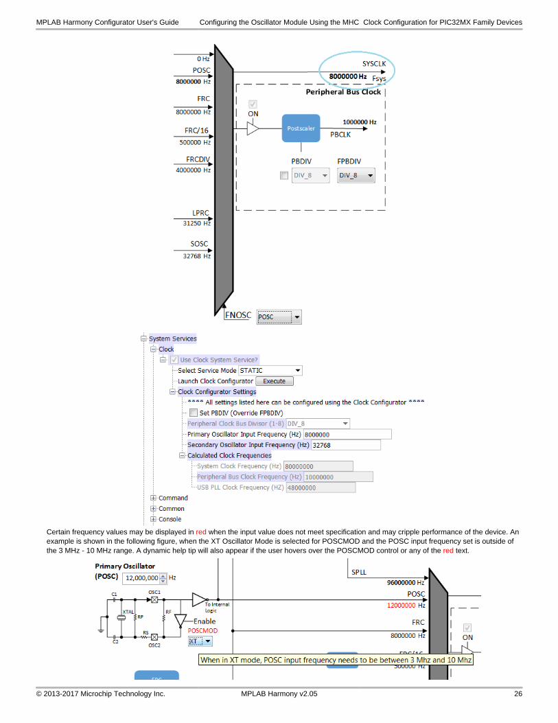
Certain frequency values may be displayed in red when the input value does not meet specification and may cripple performance of the device. An example is shown in the following figure, when the XT Oscillator Mode is selected for POSCMOD and the POSC input frequency set is outside of the 3 MHz - 10 MHz range. A dynamic help tip will also appear if the user hovers over the POSCMOD control or any of the red text.
MPLAB Harmony Configurator User's Guide Configuring the Oscillator Module Using the MHC Clock Configuration for PIC32MX Family Devices
© 2013-2017 Microchip Technology Inc. MPLAB Harmony v2.05 26
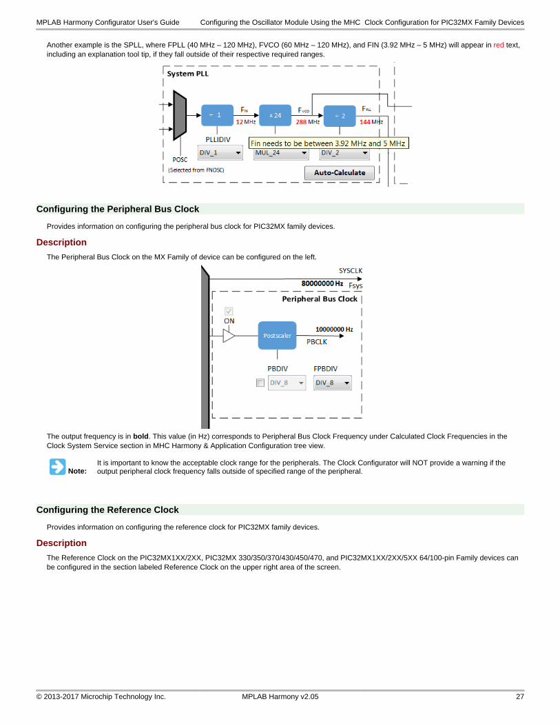
Another example is the SPLL, where FPLL (40 MHz – 120 MHz), FVCO (60 MHz – 120 MHz), and FIN (3.92 MHz – 5 MHz) will appear in red text, including an explanation tool tip, if they fall outside of their respective required ranges.
Configuring the Peripheral Bus Clock
Provides information on configuring the peripheral bus clock for PIC32MX family devices.
Description
The Peripheral Bus Clock on the MX Family of device can be configured on the left.
The output frequency is in bold. This value (in Hz) corresponds to Peripheral Bus Clock Frequency under Calculated Clock Frequencies in the Clock System Service section in MHC Harmony & Application Configuration tree view.
Note:It is important to know the acceptable clock range for the peripherals. The Clock Configurator will NOT provide a warning if the output peripheral clock frequency falls outside of specified range of the peripheral.
Configuring the Reference Clock
Provides information on configuring the reference clock for PIC32MX family devices.
Description
The Reference Clock on the PIC32MX1XX/2XX, PIC32MX 330/350/370/430/450/470, and PIC32MX1XX/2XX/5XX 64/100-pin Family devices can be configured in the section labeled Reference Clock on the upper right area of the screen.
MPLAB Harmony Configurator User's Guide Configuring the Oscillator Module Using the MHC Clock Configuration for PIC32MX Family Devices
© 2013-2017 Microchip Technology Inc. MPLAB Harmony v2.05 27
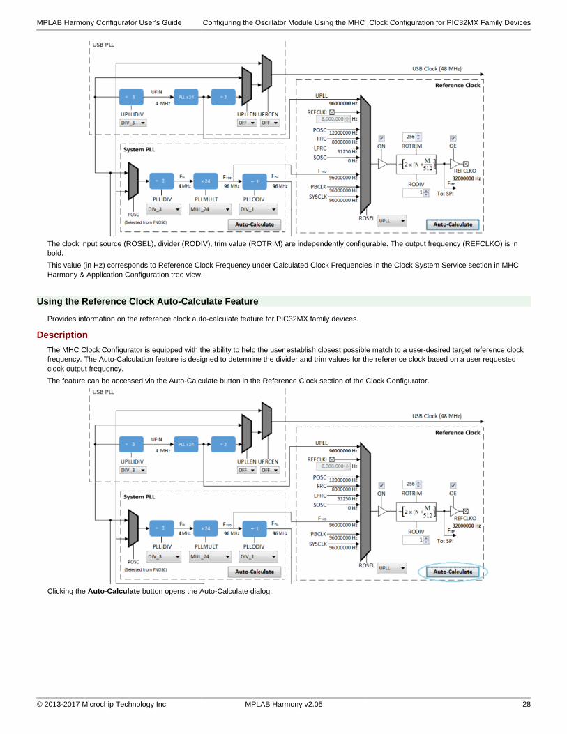
The clock input source (ROSEL), divider (RODIV), trim value (ROTRIM) are independently configurable. The output frequency (REFCLKO) is in bold.
This value (in Hz) corresponds to Reference Clock Frequency under Calculated Clock Frequencies in the Clock System Service section in MHC Harmony & Application Configuration tree view.
Using the Reference Clock Auto-Calculate Feature
Provides information on the reference clock auto-calculate feature for PIC32MX family devices.
Description
The MHC Clock Configurator is equipped with the ability to help the user establish closest possible match to a user-desired target reference clock frequency. The Auto-Calculation feature is designed to determine the divider and trim values for the reference clock based on a user requested clock output frequency.
The feature can be accessed via the Auto-Calculate button in the Reference Clock section of the Clock Configurator.
Clicking the Auto-Calculate button opens the Auto-Calculate dialog.
MPLAB Harmony Configurator User's Guide Configuring the Oscillator Module Using the MHC Clock Configuration for PIC32MX Family Devices
© 2013-2017 Microchip Technology Inc. MPLAB Harmony v2.05 28
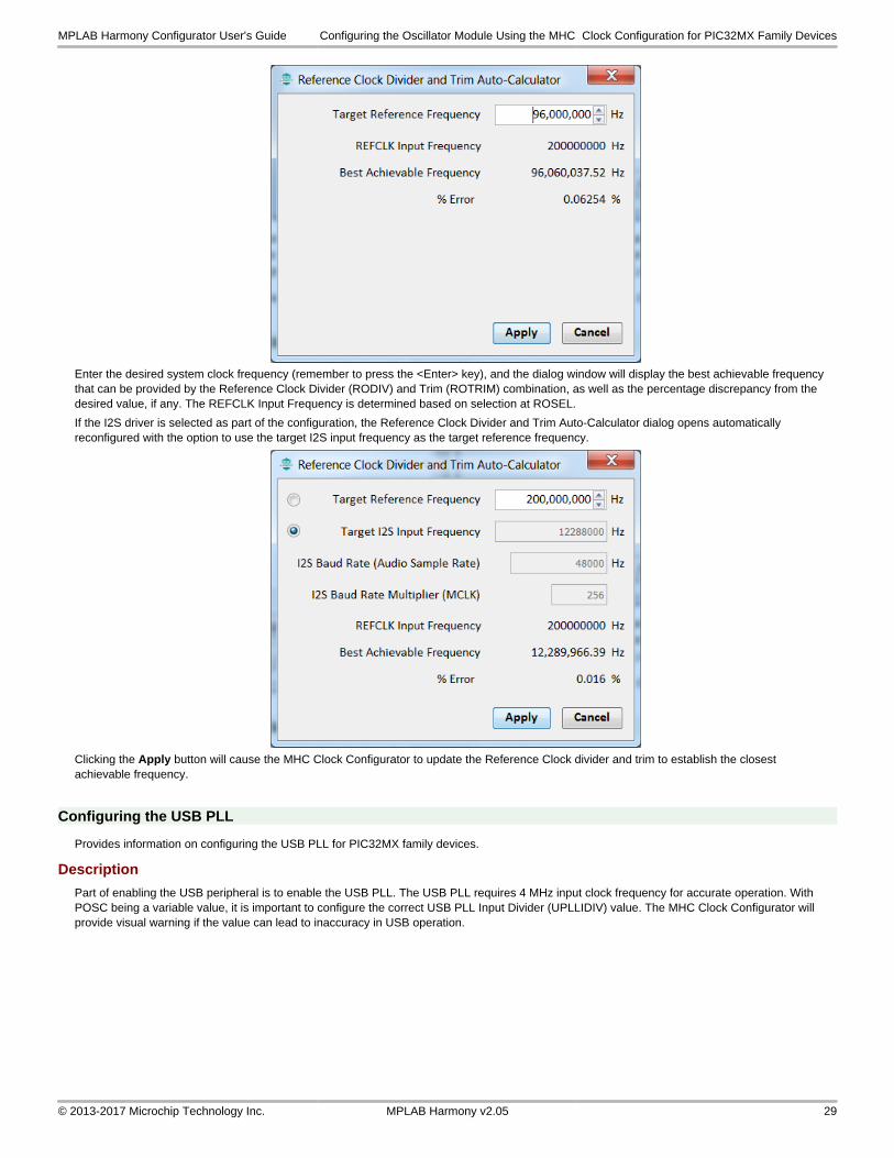
Enter the desired system clock frequency (remember to press the <Enter> key), and the dialog window will display the best achievable frequency that can be provided by the Reference Clock Divider (RODIV) and Trim (ROTRIM) combination, as well as the percentage discrepancy from the desired value, if any. The REFCLK Input Frequency is determined based on selection at ROSEL.
If the I2S driver is selected as part of the configuration, the Reference Clock Divider and Trim Auto-Calculator dialog opens automatically reconfigured with the option to use the target I2S input frequency as the target reference frequency.
Clicking the Apply button will cause the MHC Clock Configurator to update the Reference Clock divider and trim to establish the closest achievable frequency.
Configuring the USB PLL
Provides information on configuring the USB PLL for PIC32MX family devices.
Description
Part of enabling the USB peripheral is to enable the USB PLL. The USB PLL requires 4 MHz input clock frequency for accurate operation. With POSC being a variable value, it is important to configure the correct USB PLL Input Divider (UPLLIDIV) value. The MHC Clock Configurator will provide visual warning if the value can lead to inaccuracy in USB operation.
MPLAB Harmony Configurator User's Guide Configuring the Oscillator Module Using the MHC Clock Configuration for PIC32MX Family Devices
© 2013-2017 Microchip Technology Inc. MPLAB Harmony v2.05 29
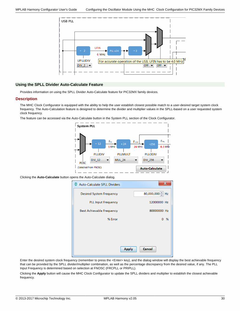
Using the SPLL Divider Auto-Calculate Feature
Provides information on using the SPLL Divider Auto-Calculate feature for PIC32MX family devices.
Description
The MHC Clock Configurator is equipped with the ability to help the user establish closest possible match to a user-desired target system clock frequency. The Auto-Calculation feature is designed to determine the divider and multiplier values in the SPLL-based on a user requested system clock frequency.
The feature can be accessed via the Auto-Calculate button in the System PLL section of the Clock Configurator.
Clicking the Auto-Calculate button opens the Auto-Calculate dialog.
Enter the desired system clock frequency (remember to press the <Enter> key), and the dialog window will display the best achievable frequency that can be provided by the SPLL divider/multiplier combination, as well as the percentage discrepancy from the desired value, if any. The PLL Input Frequency is determined based on selection at FNOSC (FRCPLL or PRIPLL).
Clicking the Apply button will cause the MHC Clock Configurator to update the SPLL dividers and multiplier to establish the closest achievable frequency.
MPLAB Harmony Configurator User's Guide Configuring the Oscillator Module Using the MHC Clock Configuration for PIC32MX Family Devices
© 2013-2017 Microchip Technology Inc. MPLAB Harmony v2.05 30
MPLAB Harmony Graphical Pin Manager
Provides information on the MPLAB Harmony Graphical Pin Manager tool that resides within MHC.
Description
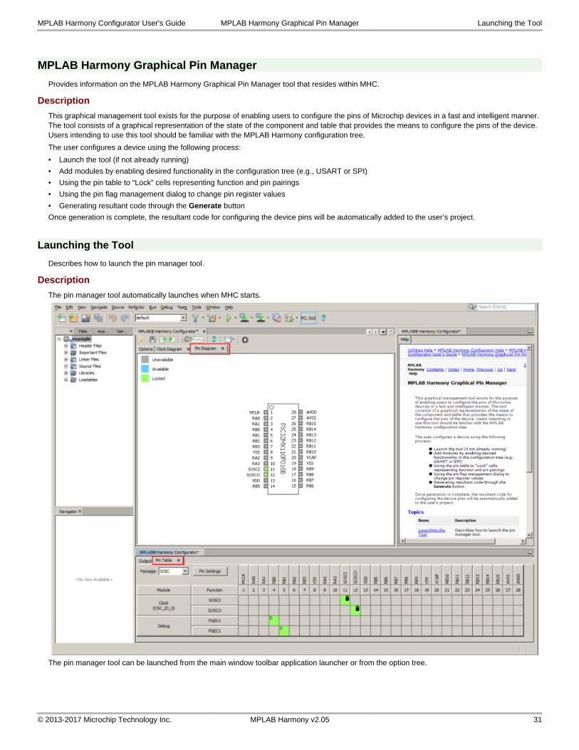
This graphical management tool exists for the purpose of enabling users to configure the pins of Microchip devices in a fast and intelligent manner. The tool consists of a graphical representation of the state of the component and table that provides the means to configure the pins of the device. Users intending to use this tool should be familiar with the MPLAB Harmony configuration tree.
The user configures a device using the following process:
• Launch the tool (if not already running)
• Add modules by enabling desired functionality in the configuration tree (e.g., USART or SPI)
• Using the pin table to “Lock” cells representing function and pin pairings
• Using the pin flag management dialog to change pin register values
• Generating resultant code through the Generate button
Once generation is complete, the resultant code for configuring the device pins will be automatically added to the user’s project.
Launching the Tool
Describes how to launch the pin manager tool.
Description
The pin manager tool automatically launches when MHC starts.
The pin manager tool can be launched from the main window toolbar application launcher or from the option tree.
MPLAB Harmony Configurator User's Guide MPLAB Harmony Graphical Pin Manager Launching the Tool
© 2013-2017 Microchip Technology Inc. MPLAB Harmony v2.05 31
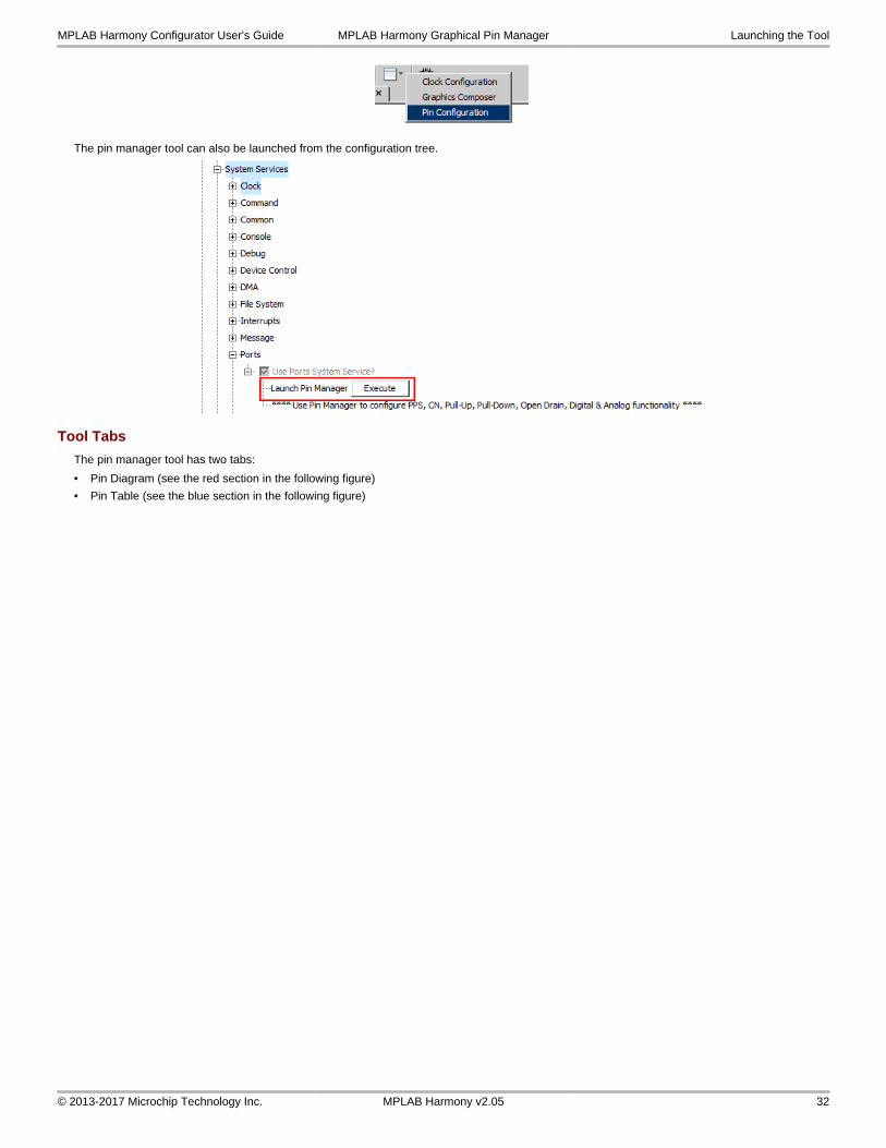
The pin manager tool can also be launched from the configuration tree.
Tool Tabs
The pin manager tool has two tabs:
• Pin Diagram (see the red section in the following figure)
• Pin Table (see the blue section in the following figure)
MPLAB Harmony Configurator User's Guide MPLAB Harmony Graphical Pin Manager Launching the Tool
© 2013-2017 Microchip Technology Inc. MPLAB Harmony v2.05 32
Pin Diagram Tab
Describes the pin diagram features.
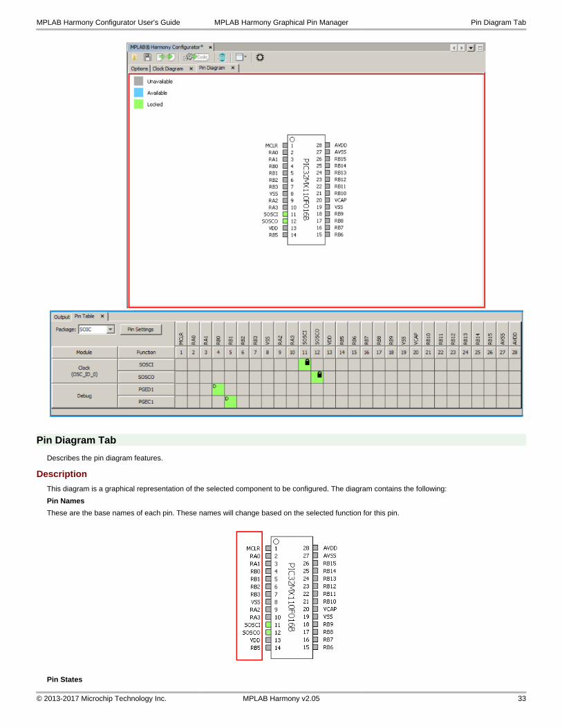
Description
This diagram is a graphical representation of the selected component to be configured. The diagram contains the following:
Pin Names
These are the base names of each pin. These names will change based on the selected function for this pin.
Pin States
MPLAB Harmony Configurator User's Guide MPLAB Harmony Graphical Pin Manager Pin Diagram Tab
© 2013-2017 Microchip Technology Inc. MPLAB Harmony v2.05 33
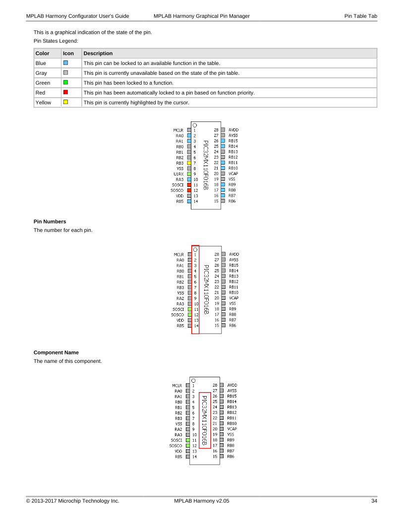
This is a graphical indication of the state of the pin.
Pin States Legend:
Color Icon Description
Blue This pin can be locked to an available function in the table.
Gray This pin is currently unavailable based on the state of the pin table.
Green This pin has been locked to a function.
Red This pin has been automatically locked to a pin based on function priority.
Yellow This pin is currently highlighted by the cursor.
Pin Numbers
The number for each pin.
Component Name
The name of this component.
MPLAB Harmony Configurator User's Guide MPLAB Harmony Graphical Pin Manager Pin Table Tab
© 2013-2017 Microchip Technology Inc. MPLAB Harmony v2.05 34
Pin Table Tab
Describes the pin table features.
Description
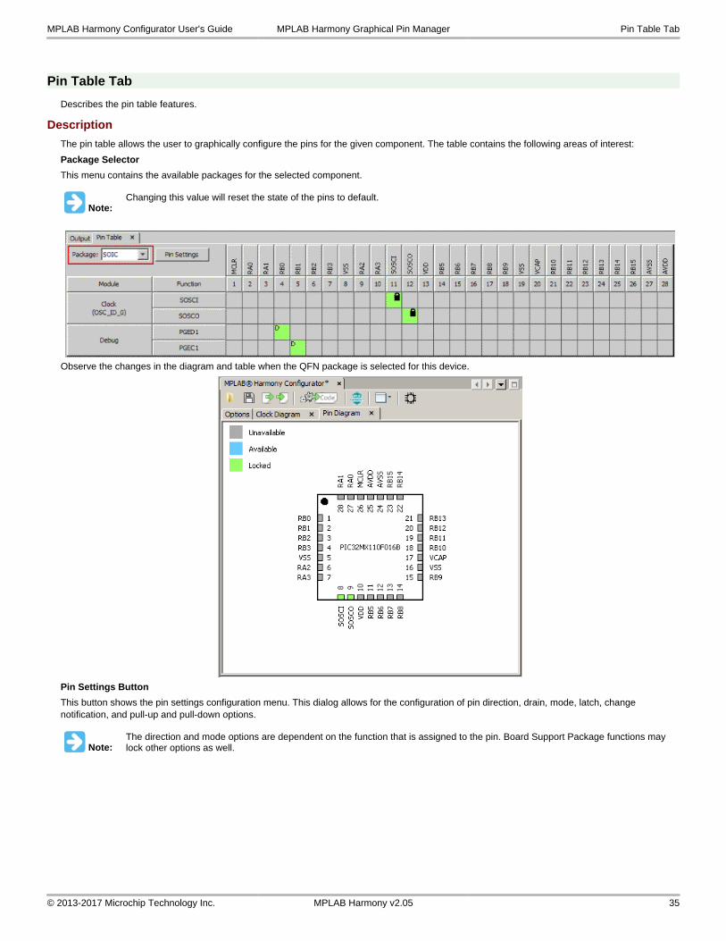
The pin table allows the user to graphically configure the pins for the given component. The table contains the following areas of interest:
Package Selector
This menu contains the available packages for the selected component.
Note:Changing this value will reset the state of the pins to default.
Observe the changes in the diagram and table when the QFN package is selected for this device.
Pin Settings Button
This button shows the pin settings configuration menu. This dialog allows for the configuration of pin direction, drain, mode, latch, change notification, and pull-up and pull-down options.
Note:The direction and mode options are dependent on the function that is assigned to the pin. Board Support Package functions may lock other options as well.
MPLAB Harmony Configurator User's Guide MPLAB Harmony Graphical Pin Manager Pin Table Tab
© 2013-2017 Microchip Technology Inc. MPLAB Harmony v2.05 35
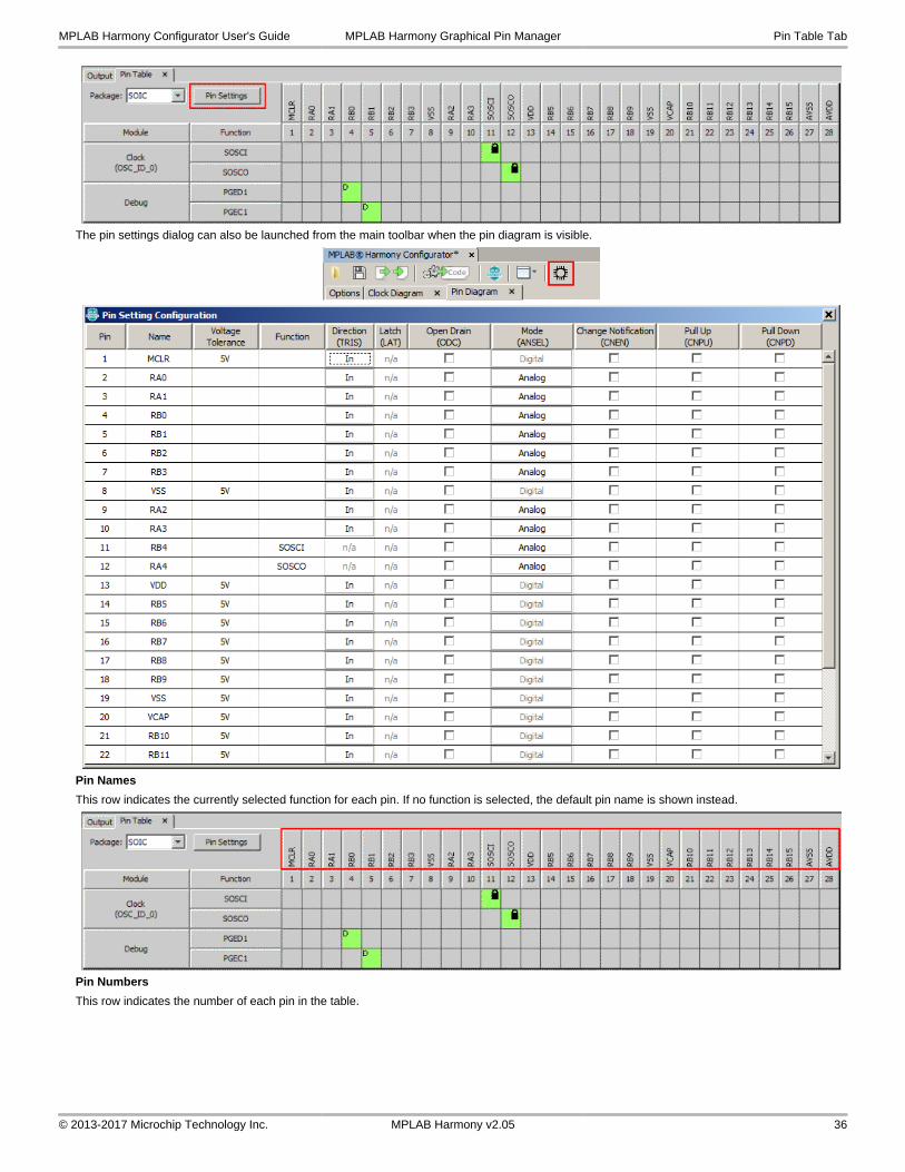
The pin settings dialog can also be launched from the main toolbar when the pin diagram is visible.
Pin Names
This row indicates the currently selected function for each pin. If no function is selected, the default pin name is shown instead.
Pin Numbers
This row indicates the number of each pin in the table.
MPLAB Harmony Configurator User's Guide MPLAB Harmony Graphical Pin Manager Pin Table Tab
© 2013-2017 Microchip Technology Inc. MPLAB Harmony v2.05 36
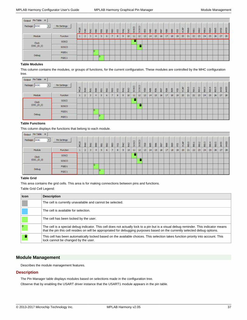
Table Modules
This column contains the modules, or groups of functions, for the current configuration. These modules are controlled by the MHC configuration tree.
Table Functions
This column displays the functions that belong to each module.
Table Grid
This area contains the grid cells. This area is for making connections between pins and functions.
Table Grid Cell Legend:
Icon Description
The cell is currently unavailable and cannot be selected.
The cell is available for selection.
The cell has been locked by the user.
The cell is a special debug indicator. This cell does not actually lock to a pin but is a visual debug reminder. This indicator means that the pin this cell resides on will be appropriated for debugging purposes based on the currently selected debug options.
This cell has been automatically locked based on the available choices. This selection takes function priority into account. This lock cannot be changed by the user.
Module Management
Describes the module management features.
Description
The Pin Manager table displays modules based on selections made in the configuration tree.
Observe that by enabling the USART driver instance that the USART1 module appears in the pin table.
MPLAB Harmony Configurator User's Guide MPLAB Harmony Graphical Pin Manager Module Management
© 2013-2017 Microchip Technology Inc. MPLAB Harmony v2.05 37
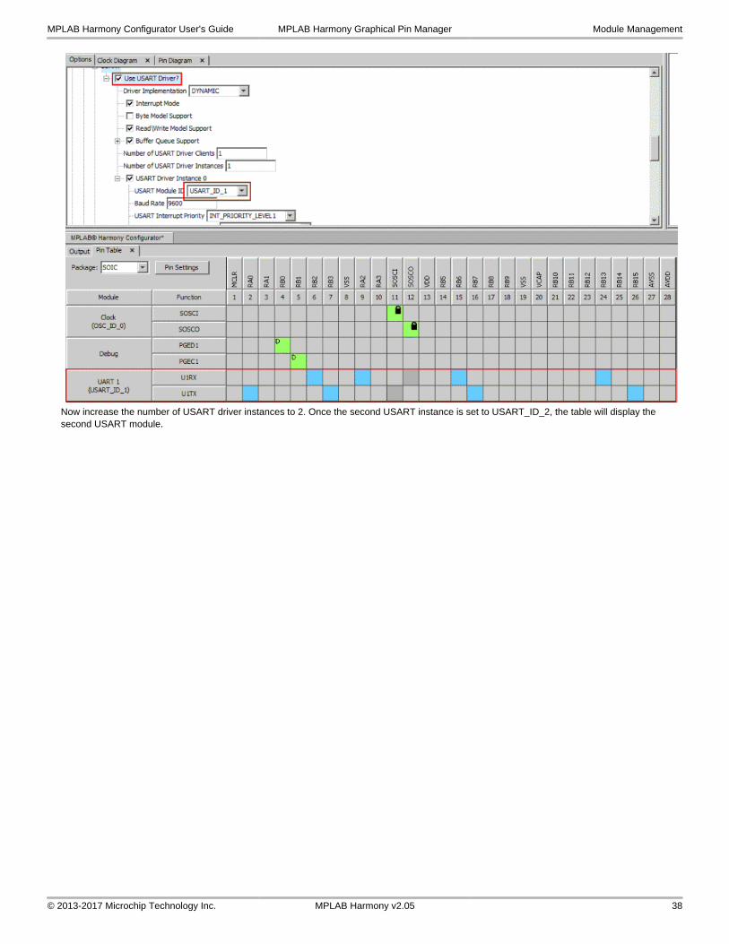
Now increase the number of USART driver instances to 2. Once the second USART instance is set to USART_ID_2, the table will display the second USART module.
MPLAB Harmony Configurator User's Guide MPLAB Harmony Graphical Pin Manager Module Management
© 2013-2017 Microchip Technology Inc. MPLAB Harmony v2.05 38
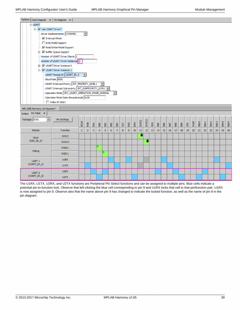
The U1RX, U1TX, U2RX, and U2TX functions are Peripheral Pin Select functions and can be assigned to multiple pins. Blue cells indicate a potential pin-to-function lock. Observe that left-clicking the blue cell corresponding to pin 9 and U1RX locks that cell to that pin/function pair. U1RX is now assigned to pin 9. Observe also that the name above pin 9 has changed to indicate the locked function, as well as the name of pin 9 in the pin diagram.
MPLAB Harmony Configurator User's Guide MPLAB Harmony Graphical Pin Manager Module Management
© 2013-2017 Microchip Technology Inc. MPLAB Harmony v2.05 39
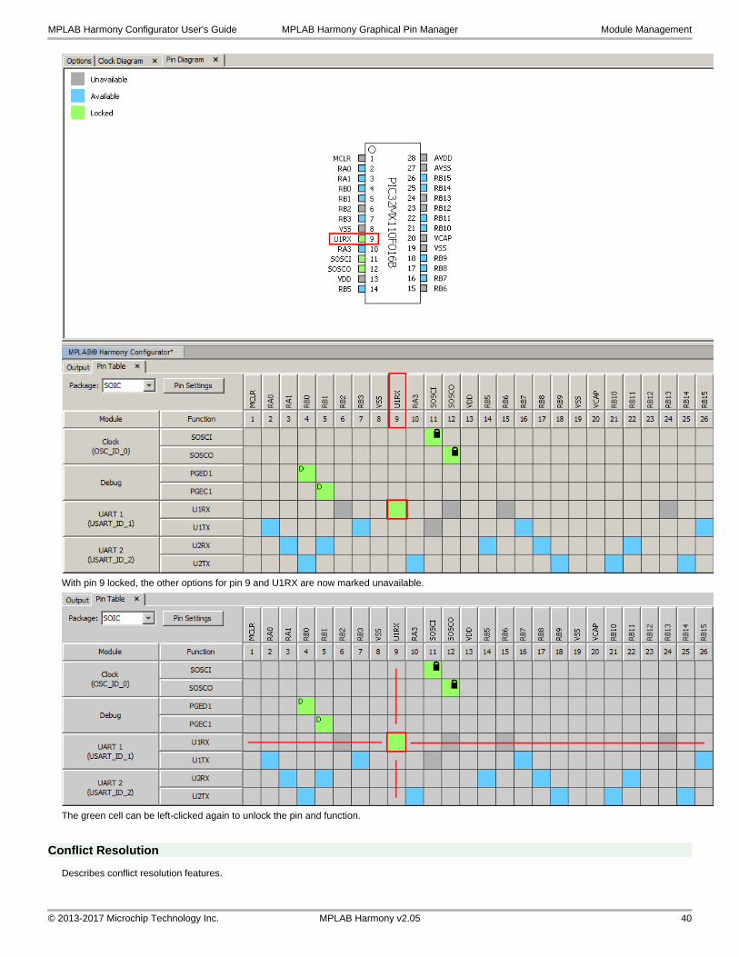
With pin 9 locked, the other options for pin 9 and U1RX are now marked unavailable.
The green cell can be left-clicked again to unlock the pin and function.
Conflict Resolution
Describes conflict resolution features.
MPLAB Harmony Configurator User's Guide MPLAB Harmony Graphical Pin Manager Module Management
© 2013-2017 Microchip Technology Inc. MPLAB Harmony v2.05 40
Description
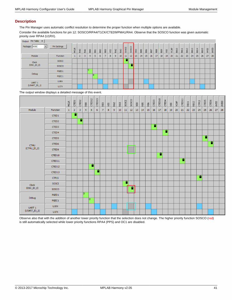
The Pin Manager uses automatic conflict resolution to determine the proper function when multiple options are available.
Consider the available functions for pin 12: SOSCO/RPA4/T1CK/CTED9/PMA1/RA4. Observe that the SOSCO function was given automatic priority over RPA4 (U1RX).
The output window displays a detailed message of this event.
Observe also that with the addition of another lower priority function that the selection does not change. The higher priority function SOSCO (red) is still automatically selected while lower priority functions RPA4 (PPS) and OC1 are disabled.
MPLAB Harmony Configurator User's Guide MPLAB Harmony Graphical Pin Manager Module Management
© 2013-2017 Microchip Technology Inc. MPLAB Harmony v2.05 41
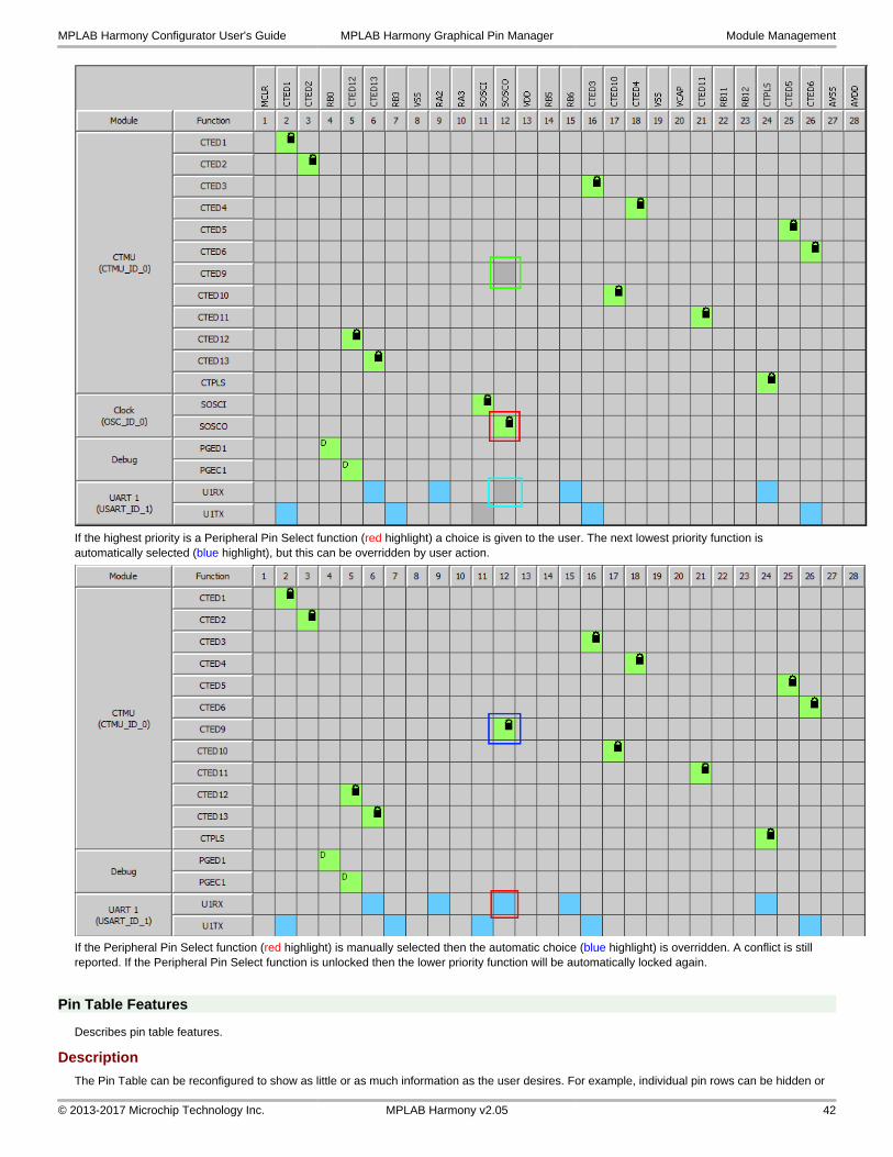
If the highest priority is a Peripheral Pin Select function (red highlight) a choice is given to the user. The next lowest priority function is automatically selected (blue highlight), but this can be overridden by user action.
If the Peripheral Pin Select function (red highlight) is manually selected then the automatic choice (blue highlight) is overridden. A conflict is still reported. If the Peripheral Pin Select function is unlocked then the lower priority function will be automatically locked again.
Pin Table Features
Describes pin table features.
Description
The Pin Table can be reconfigured to show as little or as much information as the user desires. For example, individual pin rows can be hidden or
MPLAB Harmony Configurator User's Guide MPLAB Harmony Graphical Pin Manager Module Management
© 2013-2017 Microchip Technology Inc. MPLAB Harmony v2.05 42
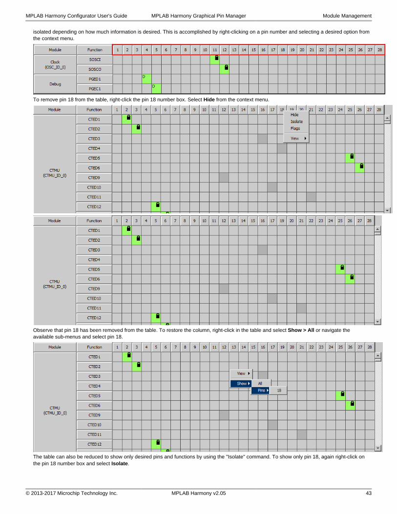
isolated depending on how much information is desired. This is accomplished by right-clicking on a pin number and selecting a desired option from the context menu.
To remove pin 18 from the table, right-click the pin 18 number box. Select Hide from the context menu.
Observe that pin 18 has been removed from the table. To restore the column, right-click in the table and select Show > All or navigate the available sub-menus and select pin 18.
The table can also be reduced to show only desired pins and functions by using the "Isolate" command. To show only pin 18, again right-click on the pin 18 number box and select Isolate.
MPLAB Harmony Configurator User's Guide MPLAB Harmony Graphical Pin Manager Module Management
© 2013-2017 Microchip Technology Inc. MPLAB Harmony v2.05 43
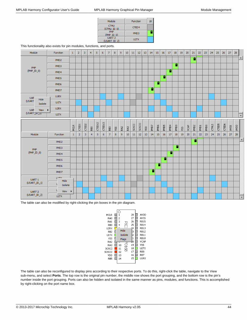
This functionality also exists for pin modules, functions, and ports.
The table can also be modified by right-clicking the pin boxes in the pin diagram.
The table can also be reconfigured to display pins according to their respective ports. To do this, right-click the table, navigate to the View sub-menu, and select Ports. The top row is the original pin number, the middle row shows the port grouping, and the bottom row is the pin’s number inside the port grouping. Ports can also be hidden and isolated in the same manner as pins, modules, and functions. This is accomplished by right-clicking on the port name box.
MPLAB Harmony Configurator User's Guide MPLAB Harmony Graphical Pin Manager Module Management
© 2013-2017 Microchip Technology Inc. MPLAB Harmony v2.05 44
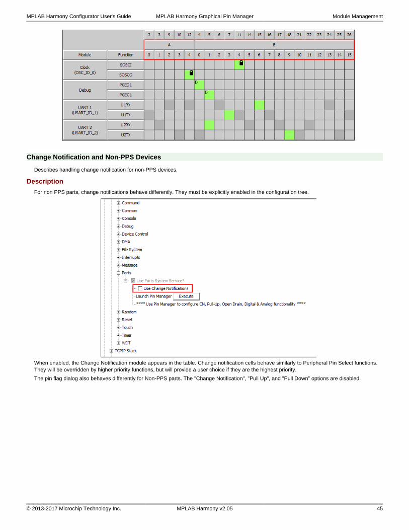
Change Notification and Non-PPS Devices
Describes handling change notification for non-PPS devices.
Description
For non PPS parts, change notifications behave differently. They must be explicitly enabled in the configuration tree.
When enabled, the Change Notification module appears in the table. Change notification cells behave similarly to Peripheral Pin Select functions. They will be overridden by higher priority functions, but will provide a user choice if they are the highest priority.
The pin flag dialog also behaves differently for Non-PPS parts. The "Change Notification", "Pull Up", and "Pull Down” options are disabled.
MPLAB Harmony Configurator User's Guide MPLAB Harmony Graphical Pin Manager Module Management
© 2013-2017 Microchip Technology Inc. MPLAB Harmony v2.05 45
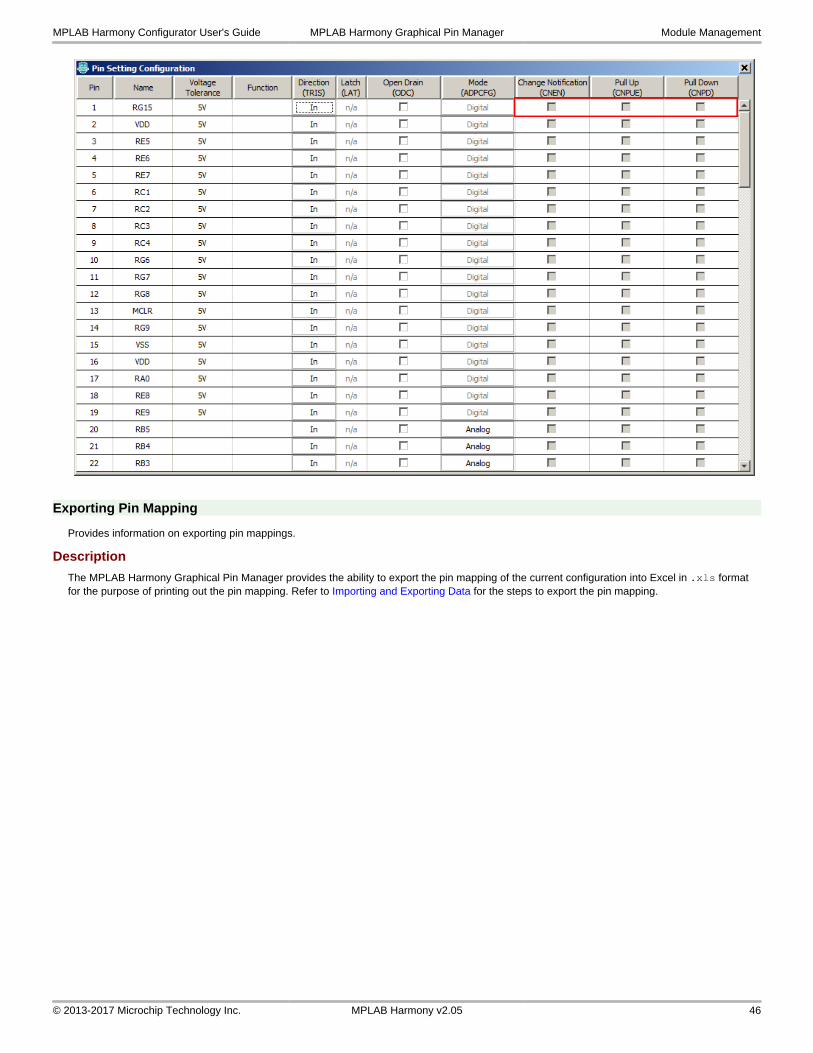
Exporting Pin Mapping
Provides information on exporting pin mappings.
Description
The MPLAB Harmony Graphical Pin Manager provides the ability to export the pin mapping of the current configuration into Excel in .xls format for the purpose of printing out the pin mapping. Refer to Importing and Exporting Data for the steps to export the pin mapping.
MPLAB Harmony Configurator User's Guide MPLAB Harmony Graphical Pin Manager Module Management
© 2013-2017 Microchip Technology Inc. MPLAB Harmony v2.05 46
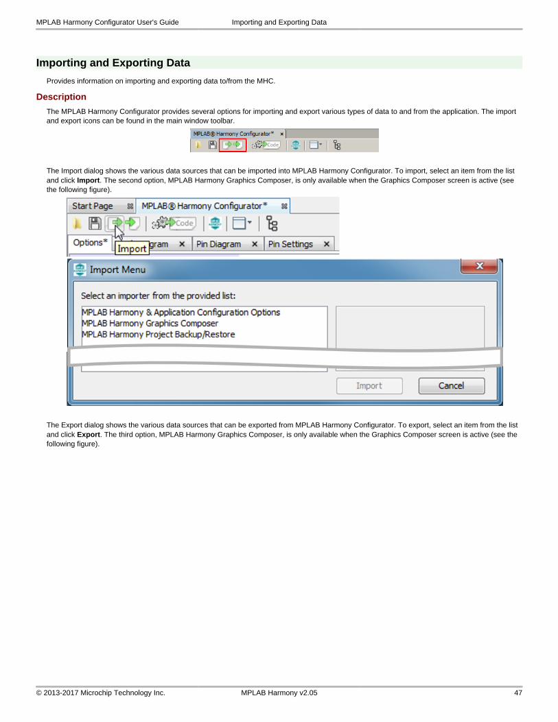
Importing and Exporting Data
Provides information on importing and exporting data to/from the MHC.
Description
The MPLAB Harmony Configurator provides several options for importing and export various types of data to and from the application. The import and export icons can be found in the main window toolbar.
The Import dialog shows the various data sources that can be imported into MPLAB Harmony Configurator. To import, select an item from the list and click Import. The second option, MPLAB Harmony Graphics Composer, is only available when the Graphics Composer screen is active (see the following figure).
The Export dialog shows the various data sources that can be exported from MPLAB Harmony Configurator. To export, select an item from the list and click Export. The third option, MPLAB Harmony Graphics Composer, is only available when the Graphics Composer screen is active (see the following figure).
MPLAB Harmony Configurator User's Guide Importing and Exporting Data
© 2013-2017 Microchip Technology Inc. MPLAB Harmony v2.05 47
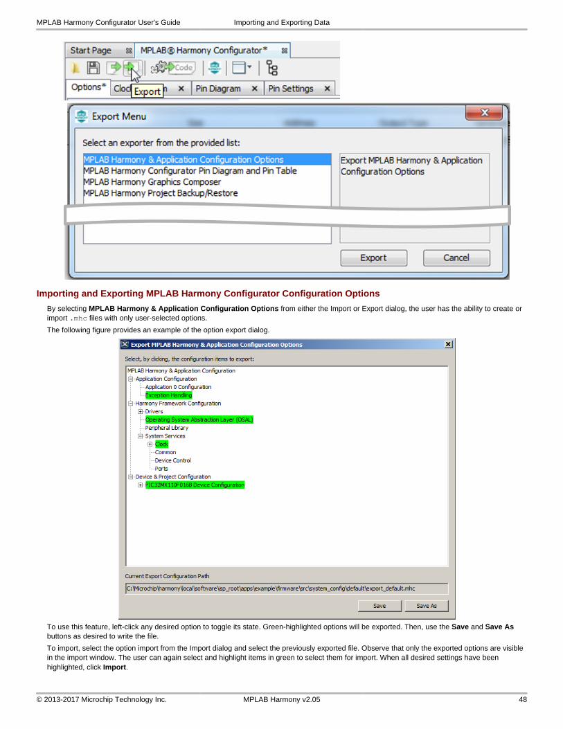
Importing and Exporting MPLAB Harmony Configurator Configuration Options
By selecting MPLAB Harmony & Application Configuration Options from either the Import or Export dialog, the user has the ability to create or import .mhc files with only user-selected options.
The following figure provides an example of the option export dialog.
To use this feature, left-click any desired option to toggle its state. Green-highlighted options will be exported. Then, use the Save and Save As buttons as desired to write the file.
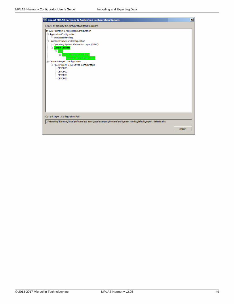
To import, select the option import from the Import dialog and select the previously exported file. Observe that only the exported options are visible in the import window. The user can again select and highlight items in green to select them for import. When all desired settings have been highlighted, click Import.
MPLAB Harmony Configurator User's Guide Importing and Exporting Data
© 2013-2017 Microchip Technology Inc. MPLAB Harmony v2.05 48
MPLAB Harmony Configurator User's Guide Importing and Exporting Data
© 2013-2017 Microchip Technology Inc. MPLAB Harmony v2.05 49
Understanding MPLAB Harmony and MHC Version Numbers
Provides information about MHC version numbering within MPLAB Harmony.
Description
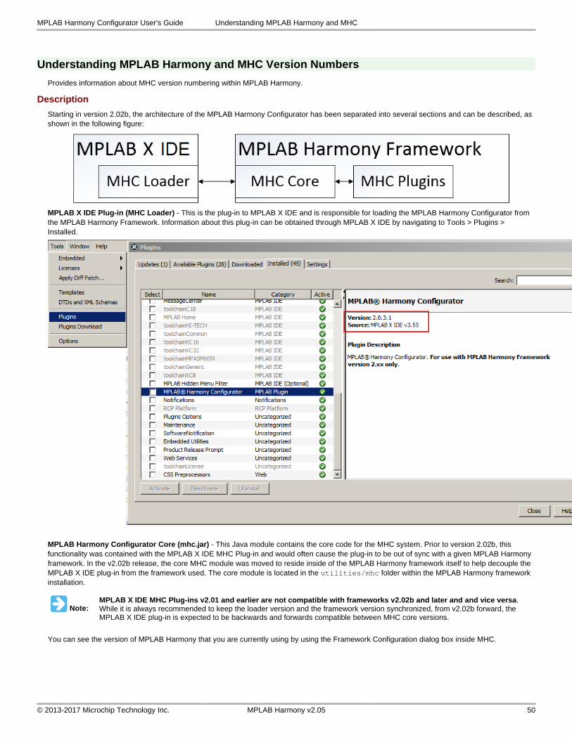
Starting in version 2.02b, the architecture of the MPLAB Harmony Configurator has been separated into several sections and can be described, as shown in the following figure:
MPLAB X IDE Plug-in (MHC Loader) - This is the plug-in to MPLAB X IDE and is responsible for loading the MPLAB Harmony Configurator from the MPLAB Harmony Framework. Information about this plug-in can be obtained through MPLAB X IDE by navigating to Tools > Plugins > Installed.
MPLAB Harmony Configurator Core (mhc.jar) - This Java module contains the core code for the MHC system. Prior to version 2.02b, this functionality was contained with the MPLAB X IDE MHC Plug-in and would often cause the plug-in to be out of sync with a given MPLAB Harmony framework. In the v2.02b release, the core MHC module was moved to reside inside of the MPLAB Harmony framework itself to help decouple the MPLAB X IDE plug-in from the framework used. The core module is located in the utilities/mhc folder within the MPLAB Harmony framework installation.
Note:MPLAB X IDE MHC Plug-ins v2.01 and earlier are not compatible with frameworks v2.02b and later and and vice versa. While it is always recommended to keep the loader version and the framework version synchronized, from v2.02b forward, the MPLAB X IDE plug-in is expected to be backwards and forwards compatible between MHC core versions.
You can see the version of MPLAB Harmony that you are currently using by using the Framework Configuration dialog box inside MHC.
MPLAB Harmony Configurator User's Guide Understanding MPLAB Harmony and MHC
© 2013-2017 Microchip Technology Inc. MPLAB Harmony v2.05 50
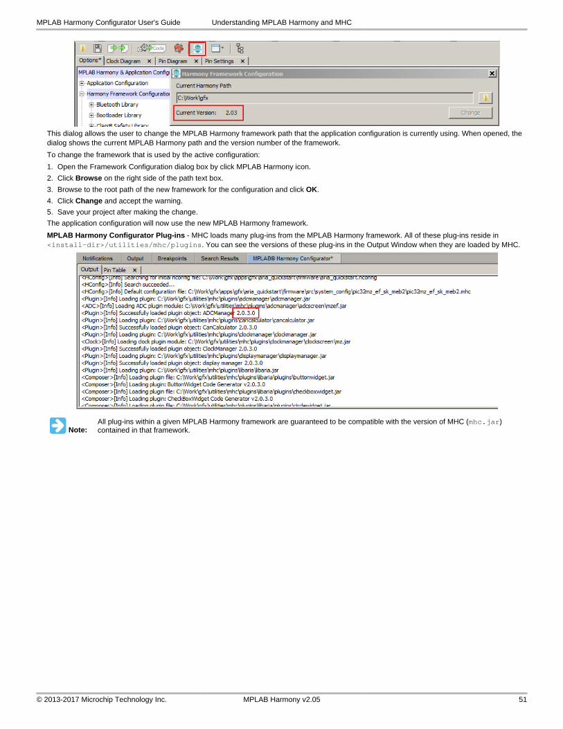
This dialog allows the user to change the MPLAB Harmony framework path that the application configuration is currently using. When opened, the dialog shows the current MPLAB Harmony path and the version number of the framework.
To change the framework that is used by the active configuration:
1. Open the Framework Configuration dialog box by click MPLAB Harmony icon.
2. Click Browse on the right side of the path text box.
3. Browse to the root path of the new framework for the configuration and click OK.
4. Click Change and accept the warning.
5. Save your project after making the change.
The application configuration will now use the new MPLAB Harmony framework.
MPLAB Harmony Configurator Plug-ins - MHC loads many plug-ins from the MPLAB Harmony framework. All of these plug-ins reside in <install-dir>/utilities/mhc/plugins. You can see the versions of these plug-ins in the Output Window when they are loaded by MHC.
Note:All plug-ins within a given MPLAB Harmony framework are guaranteed to be compatible with the version of MHC (mhc.jar) contained in that framework.
MPLAB Harmony Configurator User's Guide Understanding MPLAB Harmony and MHC
© 2013-2017 Microchip Technology Inc. MPLAB Harmony v2.05 51
Index
C
Change Notification and Non-PPS Devices 45
Clock Configuration for PIC32MX Family Devices 22
Clock Configuration for PIC32MZ Family Devices 15
Configuring the Oscillator Module Using the MHC Clock Configurator 15
Configuring the Peripheral Bus Clock 27
Configuring the Peripheral Bus Clocks 19
Configuring the Reference Clock 27
Configuring the Reference Clocks 19
Configuring the System Clock Frequency 16, 24
Configuring the USB PLL 29
Conflict Resolution 40
E
Exporting Pin Mapping 46
I
Importing and Exporting Data 47
Installing MHC 3
Introduction 10
L
Launching the Tool 31
M
Module Management 37
MPLAB Harmony Configurator Interface 5
MPLAB Harmony Configurator User's Guide 2
MPLAB Harmony Graphical Pin Manager 31
P
Pin Diagram Tab 33
Pin Table Features 42
Pin Table Tab 35
Porting a Legacy PLIB to MPLAB Harmony 14
Prerequisites 10
S
Step 1: Create the New Project 10
Step 2: Add and Configure the Required Libraries and Modules 12
Step 3: MPLAB Harmony Application Structure and Developing the Application 12
U
Understanding MPLAB Harmony and MHC Version Numbers 50
Using MHC to Create a New Application 10
Using the Reference Clock Auto-Calculate Feature 20, 28
Using the SPLL Divider Auto-Calculate Feature 21, 30
Index
© 2013-2017 Microchip Technology Inc. MPLAB Harmony v2.05 52