Embed Size (px)
Citation preview
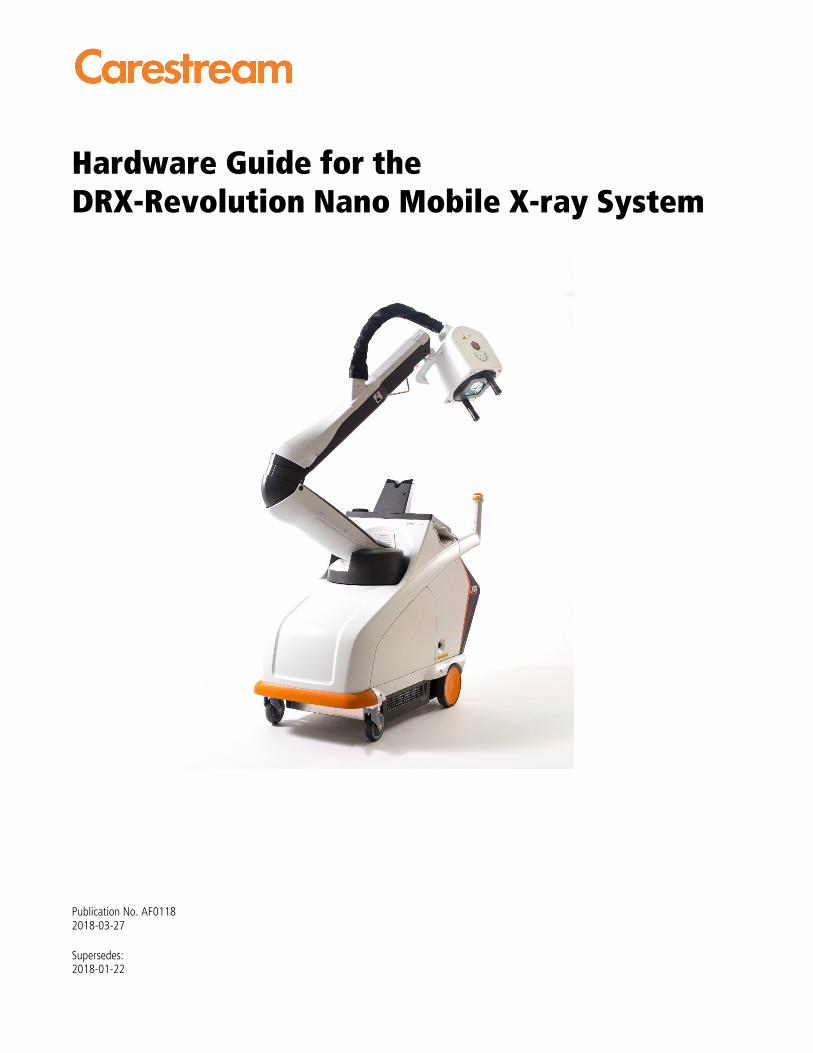
Hardware Guide for the DRX-Revolution Nano Mobile X-ray System
Publication No. AF0118 2018-03-27
Supersedes: 2018-01-22

All rights reserved. No part of this manual may be reproduced or copied in any form by any means—graphic, electronic, or mechanical, including photocopying, typing, or information retrieval systems—without written permission.
AF0118 | 2018-03-27 i
Contents
1 Overview ............................................................................................................ 1-1 Preface ......................................................................................................................................... 1-1 About this Guide ......................................................................................................................... 1-1 Related Documentation .............................................................................................................. 1-2 Intended Audience ...................................................................................................................... 1-2 Indications for Use ....................................................................................................................... 1-2 Usability ....................................................................................................................................... 1-2 Training ........................................................................................................................................ 1-2 Safe Operation Precautions ......................................................................................................... 1-3 Safety and Warning Symbols ...................................................................................................... 1-3
2 Product Description ........................................................................................... 2-1 Features and Functions ................................................................................................................ 2-1
3 Operation and Use ............................................................................................. 3-1 Operation and Use ...................................................................................................................... 3-1 Cart ............................................................................................................................................... 3-2 Cart Maneuverability and Positioning ........................................................................................ 3-4 Environmental Requirements and Infection Control ................................................................. 3-6 Acoustic Noise Emission ............................................................................................................... 3-6 Product Classification per IEC 60601-1 ........................................................................................ 3-6 Arm and Tube Head Assembly .................................................................................................... 3-7 Exposure Factors and the X-ray Tube ....................................................................................... 3-13 Time Cycle between Exposures ................................................................................................. 3-15 Component Descriptions ........................................................................................................... 3-16
4 Operating the System ........................................................................................ 4-1 Drive the Cart............................................................................................................................... 4-1 Dock and Deploy the Arm ........................................................................................................... 4-2 Operating the Machine ............................................................................................................... 4-2 Power Button Operation ............................................................................................................. 4-3
5 Maintenance and Safety Information .............................................................. 5-1 Cleaning Instructions ................................................................................................................... 5-1 With Each Occurrence of Patient Contact .................................................................................. 5-1 Cleaning the Monitor .................................................................................................................. 5-2 Cleaning the Hardware ............................................................................................................... 5-3 Cleaning the Detector ................................................................................................................. 5-4 Cleaning the Plastic Components ................................................................................................ 5-4 Cleaning the Arm ........................................................................................................................ 5-5 System Maintenance .................................................................................................................... 5-5
ii AF0118 | 2018-03-27
Reporting Unusual Conditions .................................................................................................... 5-6 Replacing the Batteries................................................................................................................ 5-6 General Safety Information ......................................................................................................... 5-7
6 Technical Specifications .................................................................................... 6-1
7 Troubleshooting ................................................................................................. 7-1 Service and Support ..................................................................................................................... 7-2 Device Identification .................................................................................................................... 7-2 Procedure for Firmware Upgrade ............................................................................................... 7-2
8 Appendix A......................................................................................................... 8-1 Optional Parts .............................................................................................................................. 8-1
Publication History .......................................................................................................
AF0118 | 2018-03-27 1-1
1 Overview
Preface The information contained herein is based on the experience and knowledge relating to the subject matter gained by Carestream Health prior to publication.
No patent license is granted by this information.
Carestream Health reserves the right to change this information without notice, and makes no warranty, express or implied, with respect to this information. Carestream Health shall not be liable for any loss or damage, including consequential or special damages, resulting from any use of this information, even if loss or damage is caused by Carestream Health’s negligence or other fault.
About this Guide
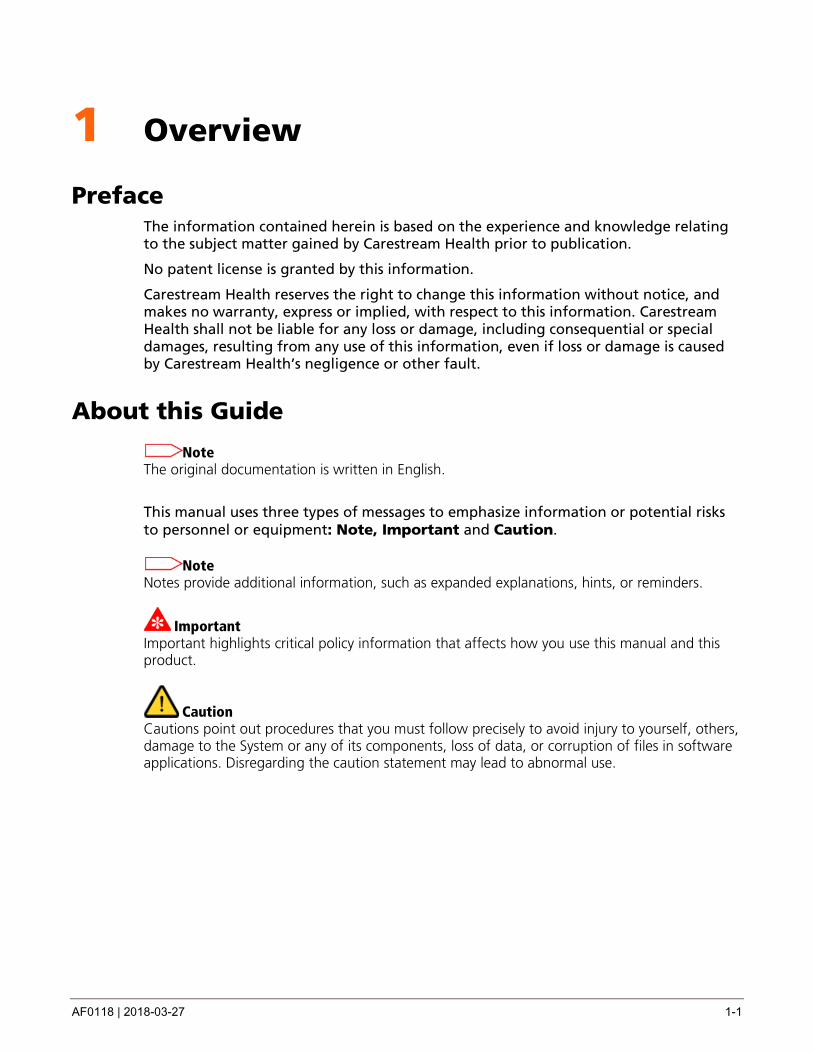
Note The original documentation is written in English.
This manual uses three types of messages to emphasize information or potential risks to personnel or equipment: Note, Important and Caution.
Note Notes provide additional information, such as expanded explanations, hints, or reminders.
Important Important highlights critical policy information that affects how you use this manual and this product.
Caution Cautions point out procedures that you must follow precisely to avoid injury to yourself, others, damage to the System or any of its components, loss of data, or corruption of files in software applications. Disregarding the caution statement may lead to abnormal use.

Overview
1-2 AF0118 | 2018-03-27
Related Documentation • DRX-Revolution Nano Mobile X-ray System Safety and Regulatory Information
• DirectView Online Help Topics and DirectView Software User Release Notes
• DRX-Revolution Nano Mobile X-ray System User Release Notes
• DRX-Revolution Nano Mobile X-ray System Installation Guide
• DRX-Revolution Nano Mobile X-ray System Preventative Maintenance Guide
• DRX-Revolution Nano Mobile X-ray System Site Specification Guide
• User Guide for Remote Exposure Switches for Mobile X-ray Systems
Intended Audience The audience for this guide includes technologists, radiologists, service engineers, and quality assurance technicians.
Indications for Use The device is designed to perform radiographic X-ray examinations on pediatric and adult patients, in all treatment areas. Mammography examinations are excluded.
Usability The design and development of this diagnostic X-ray system incorporated a usability engineering process in accordance with IEC 60601-1-6: Medical Electrical Equipment, Part 1-6: General requirements for safety. Collateral Standard: Usability
Training This equipment is intended for use by appropriately educated and skilled radiological health care professionals who have received specific training on the operation and use of this equipment.
Caution
Only qualified, trained X-ray personnel should operate the System. Operation of the equipment by persons who have not been trained or who are unfamiliar with the functions and controls of the System may cause serious injury to the patient, serious injury to the operator, or equipment damage.
Caution Federal law restricts this device to sale by or on the order of a physician.
Overview
AF0118 | 2018-03-27 1-3
Safe Operation Precautions Personnel operating and maintaining this equipment should be familiar with all aspects of operation and maintenance. To ensure safety, read the DRX-Revolution Nano Mobile X-ray System Safety and Regulatory Information carefully before using the system and observe all Cautions, Importants, and Notes located throughout the manual.
Important For continued safe use of this equipment, follow the instructions contained in this operating manual.
Important Study this manual carefully before using the equipment and keep it at hand for quick reference.
The equipment must be used only by qualified personnel and only after training in the specific operations. It is the operator's responsibility to ensure the patient's safety by visual observation, audio communication, proper patient positioning, and use of the protective devices.
Thoroughly check that there is no interference or possibility of collision between the patient and other equipment.
Maintain the equipment periodically to ensure continued safe use of the equipment. See “Chapter 5 Maintenance and Safety Information” for periodic maintenance recommendations.
The equipment must be installed and repaired only by authorized service personnel.
For more information, see: DRX-Revolution Nano Mobile X-ray System Safety and Regulatory Information, DRX-Revolution Nano Mobile X-ray System Installation Guide, DRX-Revolution Nano Mobile X-ray System Preventative Maintenance Guide, and DRX-Revolution Nano Mobile X-ray System Site Specification Guide.
Safety and Warning Symbols For symbols that may be used for marking on this equipment, see DRX-Revolution Nano Mobile X-ray System Safety and Regulatory Information.

AF0118 | 2018-03-27 2-1
2 Product Description
The DRX-Revolution Nano Mobile X-ray System is designed specifically for Digital Radiography (DR) with Carestream-supported detectors (see Section 2.1.10). The DRX-Revolution Nano Mobile X-ray System incorporates the tools required for acquiring medical diagnostic images outside of a standard X-ray room.
The DRX-Revolution Nano Mobile X-ray System is an all-inclusive mobile X-ray system, providing:
• A high power generator (maximum 5.3 kW @ 100 msec and 7.7 kW @ 13 msec).
• A user-friendly X-ray tube head, enabling positioning in five axes of motion.
• A low-profile, ultra-lightweight arm assembly for ease of patient positioning and better visibility while driving.
• Safe storage for detectors and supplies.
• Carestream's proven user interface and image editing and processing tools.
Features and Functions The DRX-Revolution Nano Mobile X-ray System is an ultra-lightweight mobile X-ray system providing multiple features and functions.
Image Capture
The system provides:
• Easy maneuverability
• Five axes of motion of the tube head
The tube has a nominal IEC focal spot size range of 0.9 to 1.9 equivalent at 0.1 increments.
The generator provides:
• Maximum 5.3 kW @ 100 msec and 7.7 kW @ 13 msec of power
• 40 – 110 kV
• 0.2 – 20.0 mAs
• 30 – 80 mA
Normal operation of the system is considered to be 60 exposures in a 24-hour period.
Power
The system operates on a bank of internal rechargeable batteries mounted in an easily-removable tray, as the system is designed to be used independently of a mains power
Product Description
2-2 AF0118 | 2018-03-27
source. The battery drawer is field-removable with the use of a tool. Only trained service personnel are to remove the battery tray
The battery life allows for taking up to 40 exposures without charging. This assumes fully-charged batteries and various techniques.
Note In order to ensure that the cart is always ready to take images, it should be placed on charge whenever it is not in use.
Note Shutting down the system using the power button conserves system batteries.
Mobility
The low profile arm allows for:
• Visibility while driving.
• Access to confined spaces.
• The transport system is designed for movement and maneuverability. It can be driven on surfaces typical to hospital environments at safe walking speed (around 1.5 m/s) with the tube head docked.
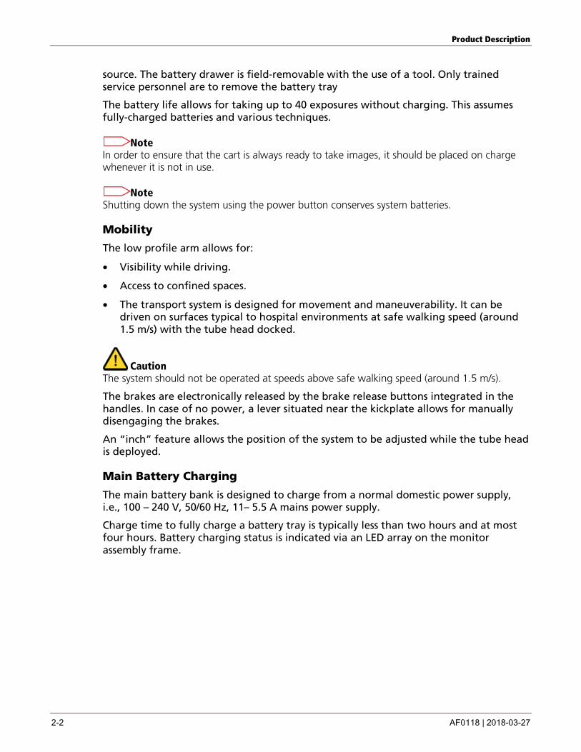
Caution The system should not be operated at speeds above safe walking speed (around 1.5 m/s).
The brakes are electronically released by the brake release buttons integrated in the handles. In case of no power, a lever situated near the kickplate allows for manually disengaging the brakes.
An “inch” feature allows the position of the system to be adjusted while the tube head is deployed.
Main Battery Charging
The main battery bank is designed to charge from a normal domestic power supply, i.e., 100 – 240 V, 50/60 Hz, 11– 5.5 A mains power supply.
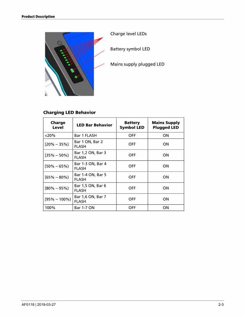
Charge time to fully charge a battery tray is typically less than two hours and at most four hours. Battery charging status is indicated via an LED array on the monitor assembly frame.
Product Description
AF0118 | 2018-03-27 2-3
Charge level LEDs
Battery symbol LED
Mains supply plugged LED
Charging LED Behavior
Charge Level
LED Bar Behavior Battery
Symbol LED Mains Supply Plugged LED
<20% Bar 1 FLASH OFF ON
[20% – 35%) Bar 1 ON, Bar 2 FLASH OFF ON
[35% – 50%) Bar 1,2 ON, Bar 3 FLASH OFF ON
[50% – 65%) Bar 1-3 ON, Bar 4 FLASH
OFF ON
[65% – 80%) Bar 1-4 ON, Bar 5 FLASH OFF ON
[80% – 95%) Bar 1,5 ON, Bar 6 FLASH OFF ON
[95% – 100%) Bar 1,6 ON, Bar 7 FLASH OFF ON
100% Bar 1-7 ON OFF ON
Product Description
2-4 AF0118 | 2018-03-27
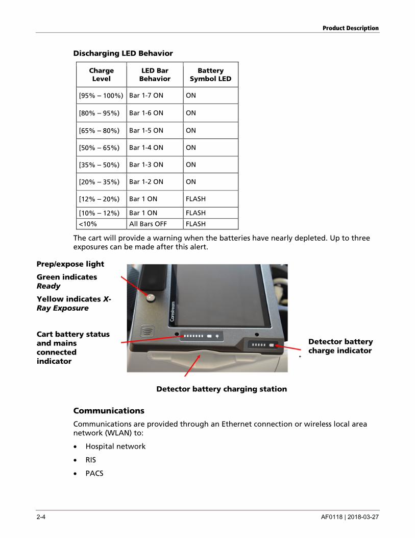
Discharging LED Behavior
Charge Level
LED Bar Behavior
Battery Symbol LED
[95% – 100%) Bar 1-7 ON ON
[80% – 95%) Bar 1-6 ON ON
[65% – 80%) Bar 1-5 ON ON
[50% – 65%) Bar 1-4 ON ON
[35% – 50%) Bar 1-3 ON ON
[20% – 35%) Bar 1-2 ON ON
[12% – 20%) Bar 1 ON FLASH
[10% – 12%) Bar 1 ON FLASH
<10% All Bars OFF FLASH
The cart will provide a warning when the batteries have nearly depleted. Up to three exposures can be made after this alert.
Prep/expose light
Green indicates Ready
Yellow indicates X-Ray Exposure
Cart battery status and mains connected indicator
Detector battery charge indicator
Detector battery charging station
Communications
Communications are provided through an Ethernet connection or wireless local area network (WLAN) to:
• Hospital network
• RIS
• PACS
Product Description
AF0118 | 2018-03-27 2-5
Operator Interface
The system includes:
• Primary touchscreen monitor on the cart – 39.6 cm (15.6 in.).
• Barcode scanner – this is an option.
• Proximity card reader that scans a radio frequency identification (RFID) badge to identify the operator for logon security – this is an option.
Diagnostics
The system includes diagnostics screens that display the status of sensors, boards, brakes, releases, and other values for:
• Tube head
• Cart braking
• Battery status
• Power control board
• Interface
• Temperature
A full Service History File is also logged continuously, for diagnostic and fault finding use.
PC Controller
The PC controller includes:
• Microsoft WINDOWS
• Intel® Core™ i5 or higher
• Random access memory (RAM): 8 GB.
• 1 x Gigabit ETHERNET port
• WLAN dual band 802.11 b/g/n
Product Description
2-6 AF0118 | 2018-03-27
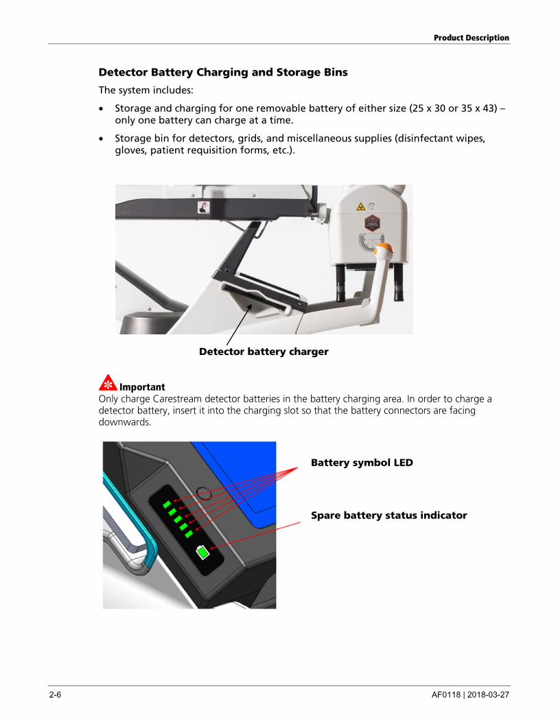
Detector Battery Charging and Storage Bins
The system includes:
• Storage and charging for one removable battery of either size (25 x 30 or 35 x 43) – only one battery can charge at a time.
• Storage bin for detectors, grids, and miscellaneous supplies (disinfectant wipes, gloves, patient requisition forms, etc.).
Detector battery charger
Important Only charge Carestream detector batteries in the battery charging area. In order to charge a detector battery, insert it into the charging slot so that the battery connectors are facing downwards.
Battery symbol LED
Spare battery status indicator
Product Description
AF0118 | 2018-03-27 2-7
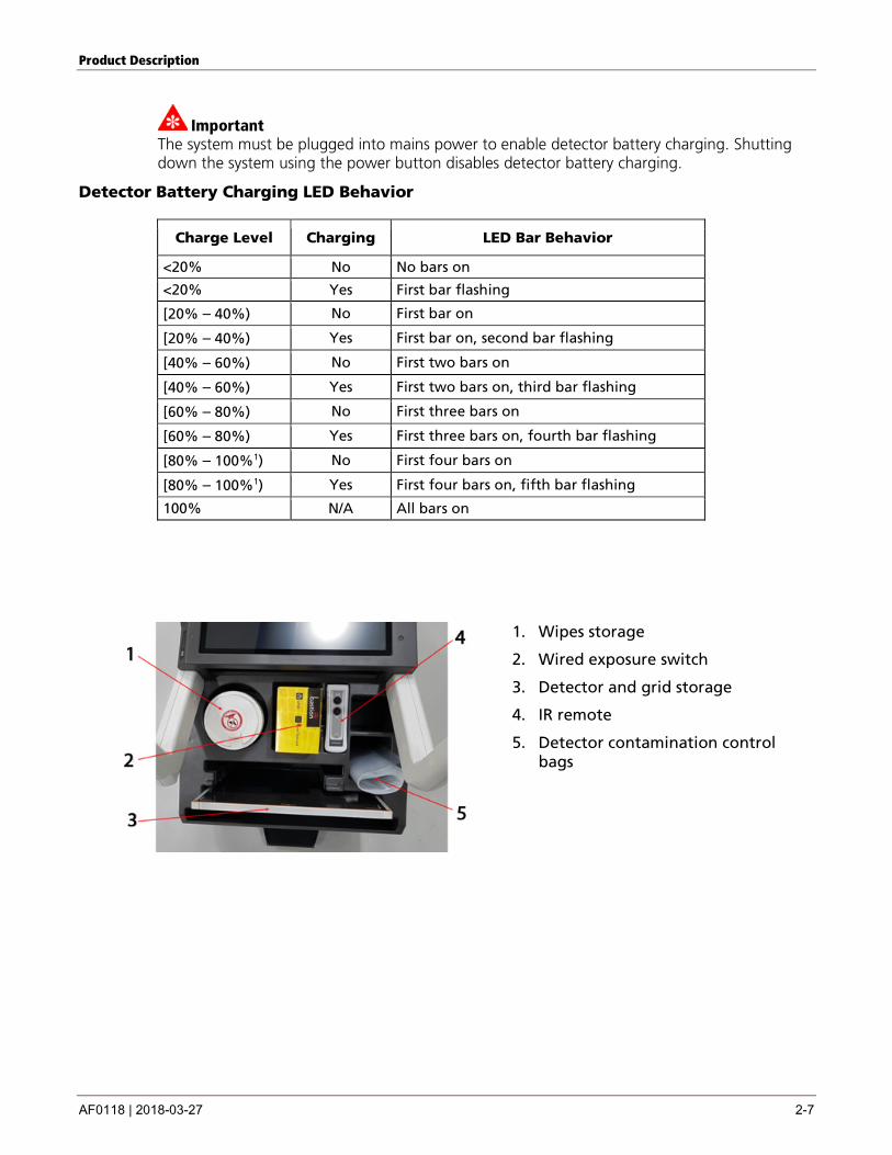
Important The system must be plugged into mains power to enable detector battery charging. Shutting down the system using the power button disables detector battery charging.
Detector Battery Charging LED Behavior
Charge Level Charging LED Bar Behavior
<20% No No bars on
<20% Yes First bar flashing
[20% – 40%) No First bar on
[20% – 40%) Yes First bar on, second bar flashing
[40% – 60%) No First two bars on
[40% – 60%) Yes First two bars on, third bar flashing
[60% – 80%) No First three bars on
[60% – 80%) Yes First three bars on, fourth bar flashing
[80% – 100%1) No First four bars on
[80% – 100%1) Yes First four bars on, fifth bar flashing
100% N/A All bars on
1. Wipes storage
2. Wired exposure switch
3. Detector and grid storage
4. IR remote
5. Detector contamination control bags
Product Description
2-8 AF0118 | 2018-03-27
Supported Detectors
• CARESTREAM DRX-1 System Detector
• CARESTREAM DRX-1C System Detector
• DRX Plus 3543 Detector, DRX Plus 3543C Detector, DRX Plus 4343 Detector and DRX Plus 4343C Detector
• DRX Core 3543 Detector, DRX Core 3543C Detector, DRX Core 4343 Detector, and DRX Core 4343C Detector
• DRX 2530C
Flat Panel Detectors (FPDs) can only be paired to one cart at a time as long as Carestream-nominated procedures are followed. Refer to the instructions for use for the particular detector being utilized.
Accessories
• Dose Area Product Meter
• Wired Exposure Switch
• Wireless infrared remote exposure switch – allowing the user to expose the patient from up to 10 meters away
• DRX Tether Cable
• RFID Proximity Badge Reader
• Pediatric Filter
Caution Please refer to instructions for use of the wireless infrared remote exposure switch.
Caution
Please refer to the individual specific manuals of the optional accessories for their instructions for use.
AF0118 | 2018-03-27 3-1
3 Operation and Use
Caution
Do not use the system in proximity to uncontrolled volumes of liquid, spills, etc.
Operation and Use While most of the components will be intuitive to an experienced radiographer, please review the parts diagrams in this document so you become familiar with the naming conventions used by Carestream Health, which are standardized throughout all of the documentation.
Operation and Use
3-2 AF0118 | 2018-03-27
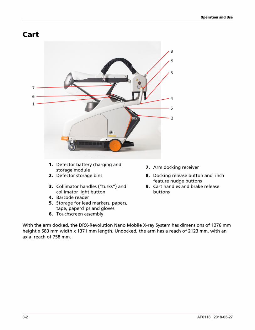
Cart
1. Detector battery charging and storage module 7. Arm docking receiver
2. Detector storage bins
8. Docking release button and inch feature nudge buttons
3. Collimator handles (“tusks”) and collimator light button
9. Cart handles and brake release buttons
4. Barcode reader 5. Storage for lead markers, papers,
tape, paperclips and gloves
6. Touchscreen assembly
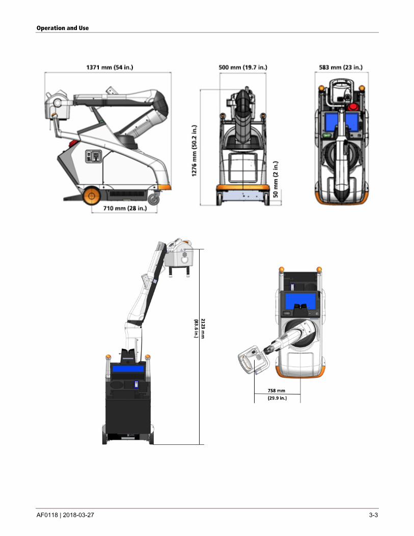
With the arm docked, the DRX-Revolution Nano Mobile X-ray System has dimensions of 1276 mm height x 583 mm width x 1371 mm length. Undocked, the arm has a reach of 2123 mm, with an axial reach of 758 mm.
Operation and Use
AF0118 | 2018-03-27 3-3
Operation and Use
3-4 AF0118 | 2018-03-27
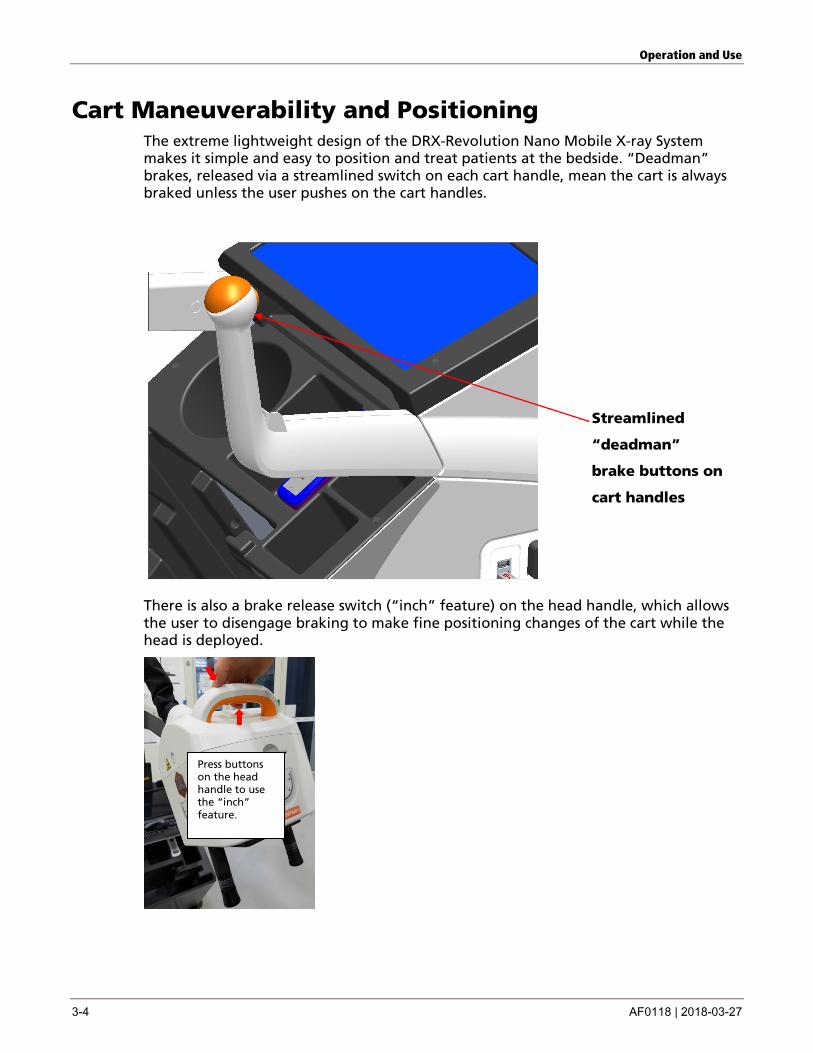
Cart Maneuverability and Positioning The extreme lightweight design of the DRX-Revolution Nano Mobile X-ray System makes it simple and easy to position and treat patients at the bedside. “Deadman” brakes, released via a streamlined switch on each cart handle, mean the cart is always braked unless the user pushes on the cart handles.
Streamlined
“deadman”
brake buttons on
cart handles
There is also a brake release switch (“inch” feature) on the head handle, which allows the user to disengage braking to make fine positioning changes of the cart while the head is deployed.
Press buttons on the head handle to use the “inch” feature.
Operation and Use
AF0118 | 2018-03-27 3-5
Caution
Check for potential obstacles prior to moving the cart using the “inch” feature.
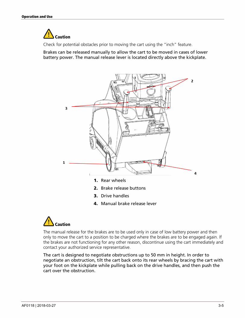
Brakes can be released manually to allow the cart to be moved in cases of lower battery power. The manual release lever is located directly above the kickplate.
1. Rear wheels
2. Brake release buttons
3. Drive handles
4. Manual brake release lever
Caution
The manual release for the brakes are to be used only in case of low battery power and then only to move the cart to a position to be charged where the brakes are to be engaged again. If the brakes are not functioning for any other reason, discontinue using the cart immediately and contact your authorized service representative.
The cart is designed to negotiate obstructions up to 50 mm in height. In order to negotiate an obstruction, tilt the cart back onto its rear wheels by bracing the cart with your foot on the kickplate while pulling back on the drive handles, and then push the cart over the obstruction.

Operation and Use
3-6 AF0118 | 2018-03-27
Environmental Requirements and Infection Control The DRX-Revolution Nano Mobile X-ray System and all its components will perform to specifications when operated in normal use under the least favorable combination of the following temperature and humidity specifications.
Environment Relative Humidity (non-condensing)
In-Use: 30 – 60 % non-condensing
Storage: 10 – 86 % non-condensing
The receiving and storage areas must be dry and able to provide the proper humidity.
Temperature In-Use: 10 to 30°C
Storage: –20 to 55 °C (–4 to 131 °F)
The DRX-Revolution Nano Mobile X-ray System is fabricated from lightweight materials to ensure transport and ease of handling characteristics, and to make the system incredibly portable to move and operate. The design is infection control-friendly, with roll edges incorporated where possible and enclosures made ingress resistant to all types of foreign matter to minimize the incidences of cross contamination and premature failure due to particulate ingress. All current infection control decontaminant products are suitable for use with the DRX-Revolution Nano Mobile X-ray System.
Acoustic Noise Emission The sound pressure level is compliant as per IEC 60601-1.
Product Classification per IEC 60601-1 Class I equipment/Internally powered.

Operation and Use
AF0118 | 2018-03-27 3-7
Arm and Tube Head Assembly
The arm assembly is a spring and gas damper counterbalanced manual four-bar linkage assembly, allowing the head to be positioned with zero-gravity stability for patient treatment, without the need for electromechanical braking, and without overloading the operator.
Operation and Use
3-8 AF0118 | 2018-03-27
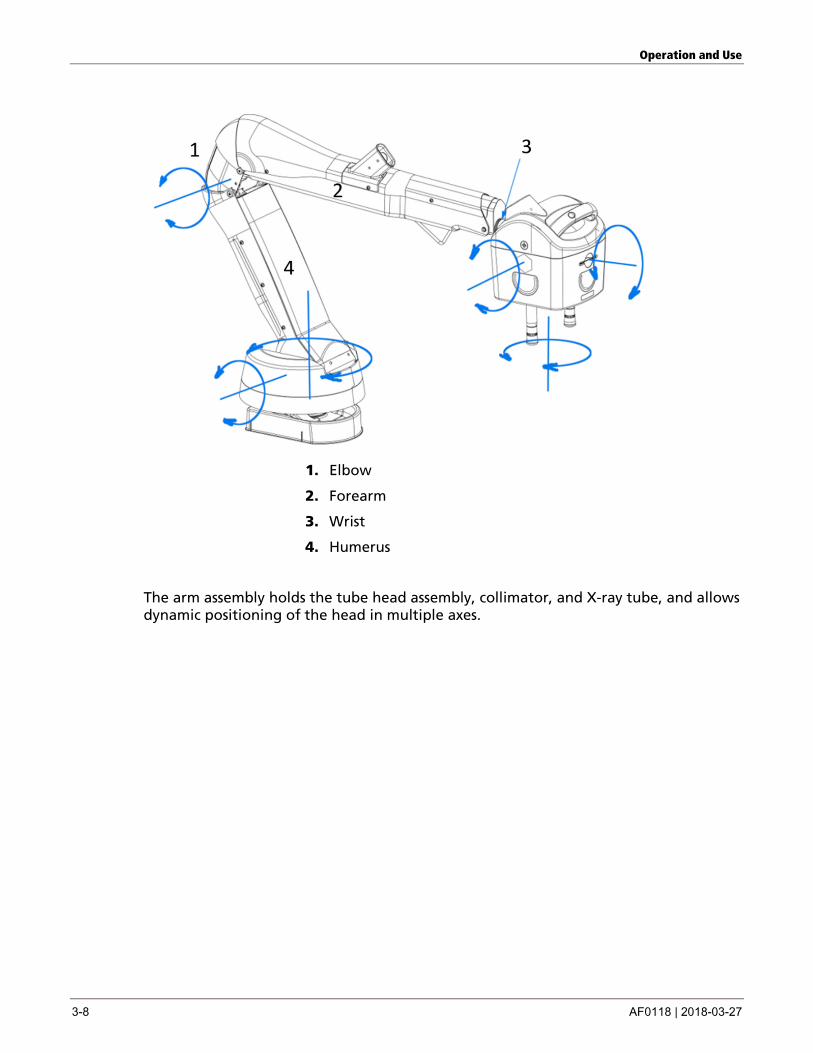
1. Elbow
2. Forearm
3. Wrist
4. Humerus
The arm assembly holds the tube head assembly, collimator, and X-ray tube, and allows dynamic positioning of the head in multiple axes.
Operation and Use
AF0118 | 2018-03-27 3-9
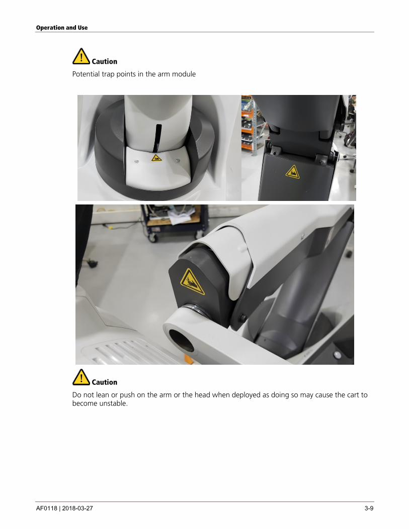
Caution
Potential trap points in the arm module
Caution
Do not lean or push on the arm or the head when deployed as doing so may cause the cart to become unstable.
Operation and Use
3-10 AF0118 | 2018-03-27
Caution
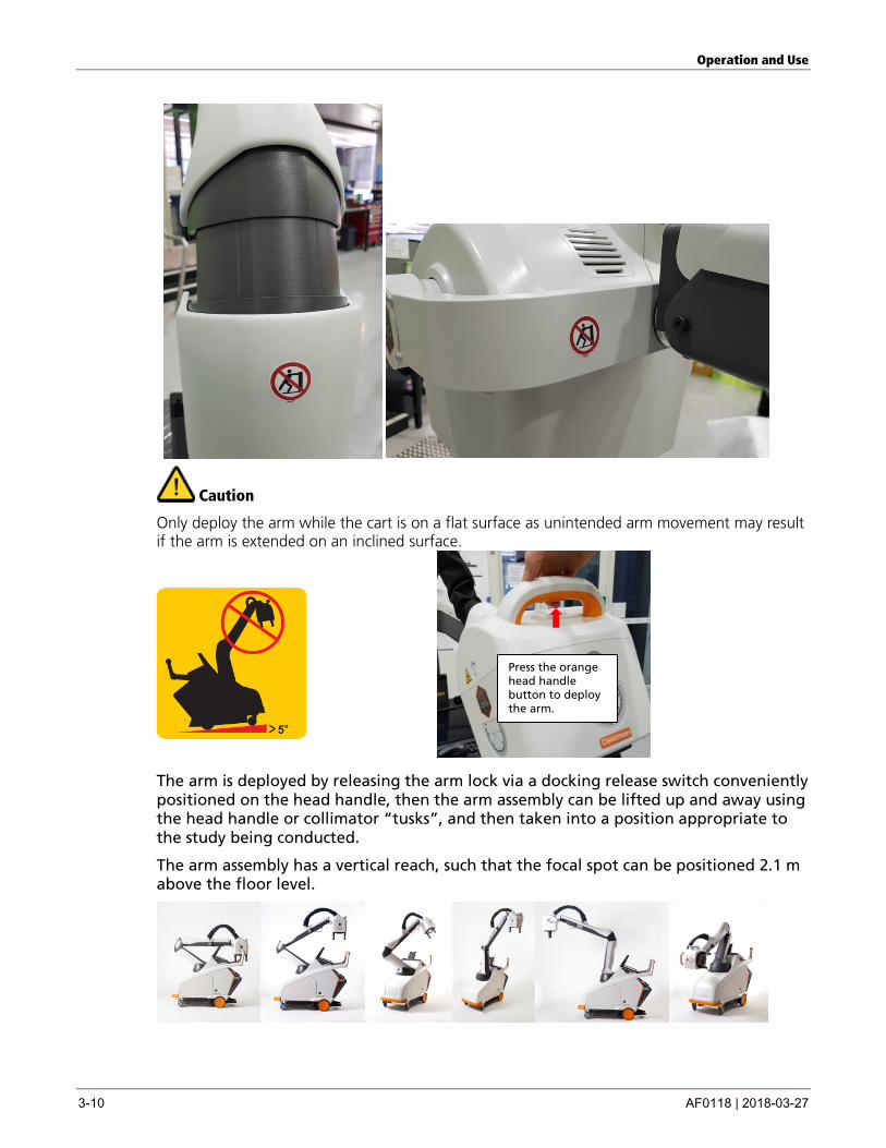
Only deploy the arm while the cart is on a flat surface as unintended arm movement may result if the arm is extended on an inclined surface.
The arm is deployed by releasing the arm lock via a docking release switch conveniently positioned on the head handle, then the arm assembly can be lifted up and away using the head handle or collimator “tusks”, and then taken into a position appropriate to the study being conducted.
The arm assembly has a vertical reach, such that the focal spot can be positioned 2.1 m above the floor level.
Press the orange head handle button to deploy the arm.
Operation and Use
AF0118 | 2018-03-27 3-11
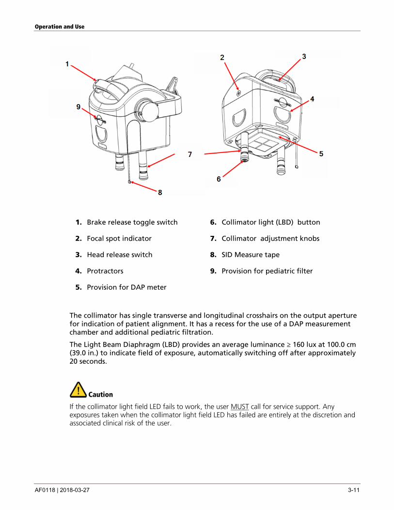
1. Brake release toggle switch 6. Collimator light (LBD) button
2. Focal spot indicator 7. Collimator adjustment knobs
3. Head release switch 8. SID Measure tape
4. Protractors 9. Provision for pediatric filter
5. Provision for DAP meter
The collimator has single transverse and longitudinal crosshairs on the output aperture for indication of patient alignment. It has a recess for the use of a DAP measurement chamber and additional pediatric filtration.
The Light Beam Diaphragm (LBD) provides an average luminance ≥ 160 lux at 100.0 cm (39.0 in.) to indicate field of exposure, automatically switching off after approximately 20 seconds.
Caution
If the collimator light field LED fails to work, the user MUST call for service support. Any exposures taken when the collimator light field LED has failed are entirely at the discretion and associated clinical risk of the user.
Operation and Use
3-12 AF0118 | 2018-03-27
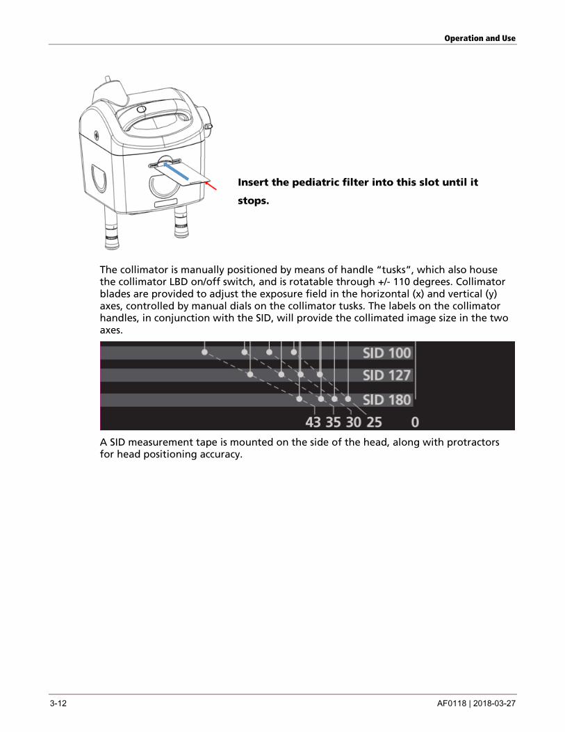
Insert the pediatric filter into this slot until it
stops.
The collimator is manually positioned by means of handle “tusks”, which also house the collimator LBD on/off switch, and is rotatable through +/- 110 degrees. Collimator blades are provided to adjust the exposure field in the horizontal (x) and vertical (y) axes, controlled by manual dials on the collimator tusks. The labels on the collimator handles, in conjunction with the SID, will provide the collimated image size in the two axes.
A SID measurement tape is mounted on the side of the head, along with protractors for head positioning accuracy.
Operation and Use
AF0118 | 2018-03-27 3-13
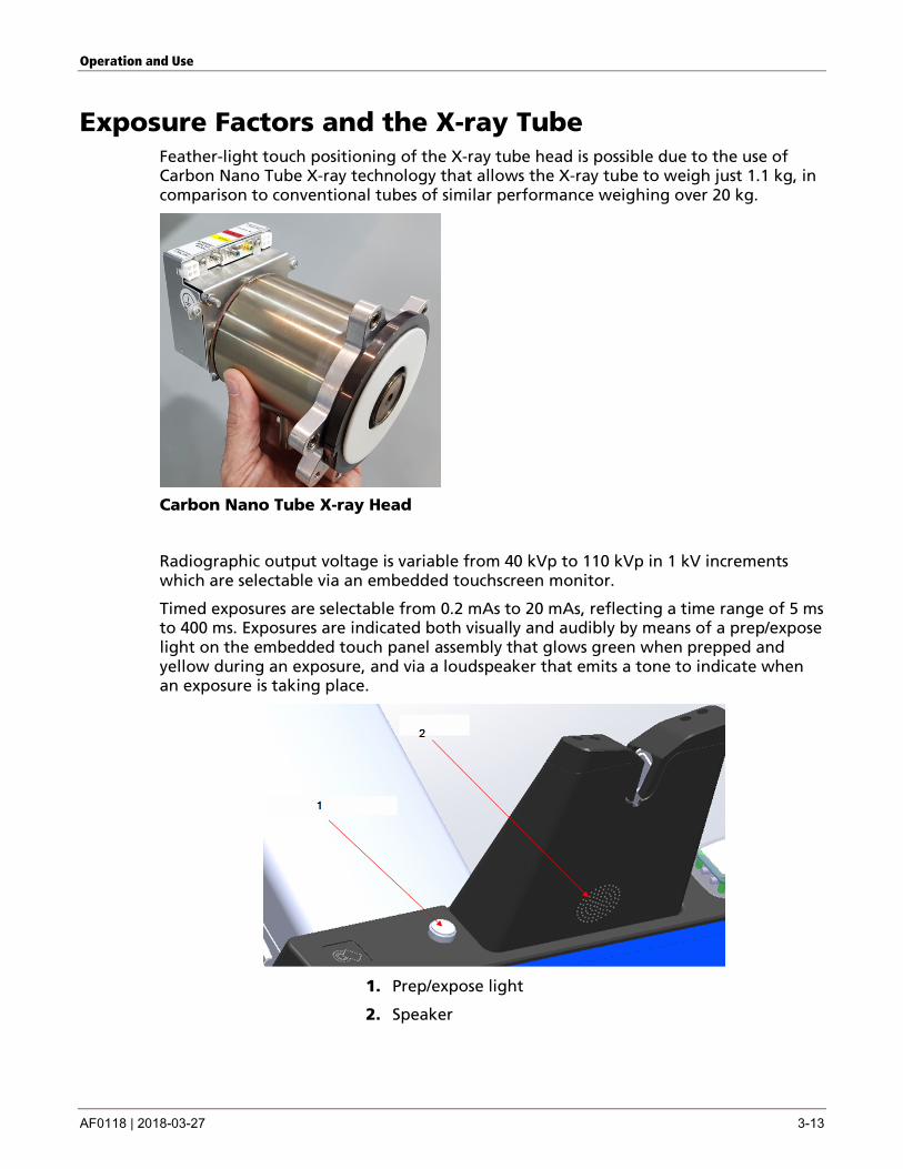
Exposure Factors and the X-ray Tube Feather-light touch positioning of the X-ray tube head is possible due to the use of Carbon Nano Tube X-ray technology that allows the X-ray tube to weigh just 1.1 kg, in comparison to conventional tubes of similar performance weighing over 20 kg.
Carbon Nano Tube X-ray Head
Radiographic output voltage is variable from 40 kVp to 110 kVp in 1 kV increments which are selectable via an embedded touchscreen monitor.
Timed exposures are selectable from 0.2 mAs to 20 mAs, reflecting a time range of 5 ms to 400 ms. Exposures are indicated both visually and audibly by means of a prep/expose light on the embedded touch panel assembly that glows green when prepped and yellow during an exposure, and via a loudspeaker that emits a tone to indicate when an exposure is taking place.
1. Prep/expose light
2. Speaker
Operation and Use
3-14 AF0118 | 2018-03-27
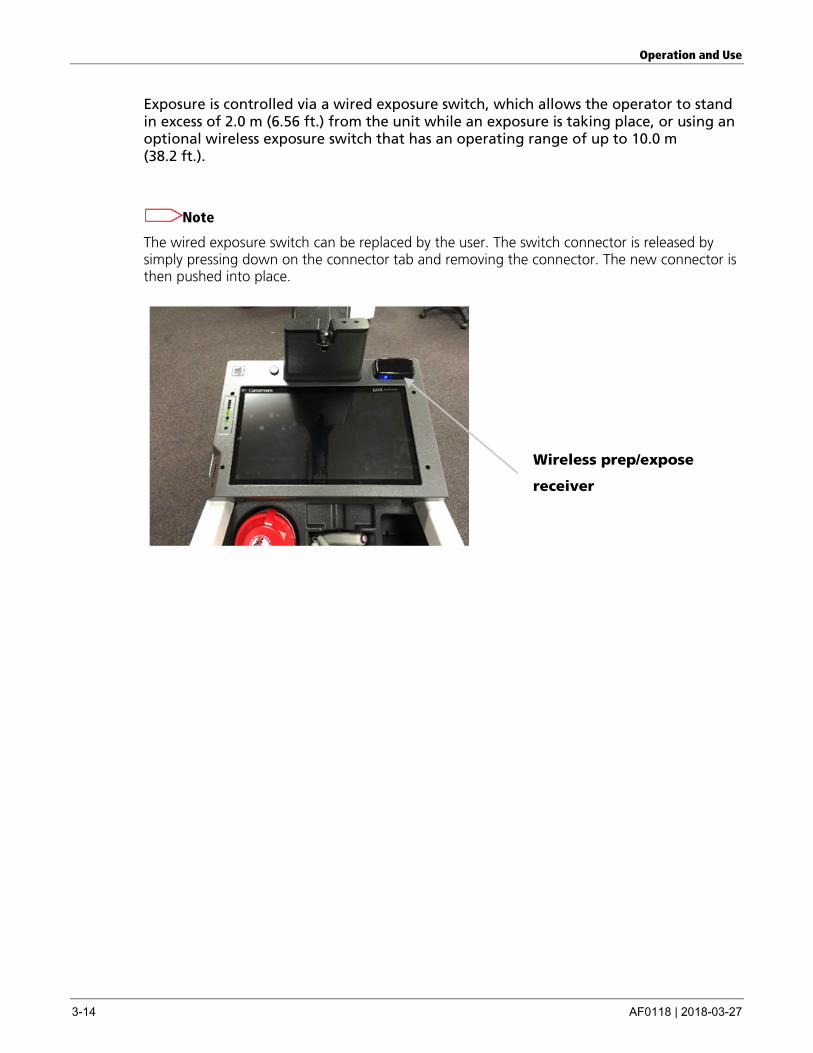
Exposure is controlled via a wired exposure switch, which allows the operator to stand in excess of 2.0 m (6.56 ft.) from the unit while an exposure is taking place, or using an optional wireless exposure switch that has an operating range of up to 10.0 m (38.2 ft.).
Note
The wired exposure switch can be replaced by the user. The switch connector is released by simply pressing down on the connector tab and removing the connector. The new connector is then pushed into place.
Wireless prep/expose
receiver
Operation and Use
AF0118 | 2018-03-27 3-15
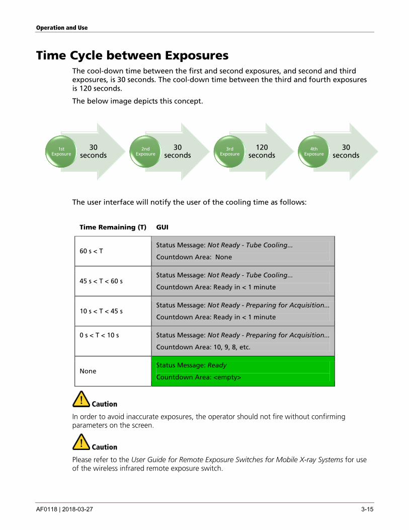
Time Cycle between Exposures The cool-down time between the first and second exposures, and second and third exposures, is 30 seconds. The cool-down time between the third and fourth exposures is 120 seconds.
The below image depicts this concept.
The user interface will notify the user of the cooling time as follows:
Time Remaining (T) GUI
60 s < T Status Message: Not Ready - Tube Cooling...
Countdown Area: None
45 s < T < 60 s Status Message: Not Ready - Tube Cooling...
Countdown Area: Ready in < 1 minute
10 s < T < 45 s Status Message: Not Ready - Preparing for Acquisition...
Countdown Area: Ready in < 1 minute
0 s < T < 10 s Status Message: Not Ready - Preparing for Acquisition...
Countdown Area: 10, 9, 8, etc.
None Status Message: Ready
Countdown Area: <empty>
Caution
In order to avoid inaccurate exposures, the operator should not fire without confirming parameters on the screen.
Caution
Please refer to the User Guide for Remote Exposure Switches for Mobile X-ray Systems for use of the wireless infrared remote exposure switch.
30 seconds
1st Exposure
30 seconds
2nd Exposure
120 seconds
3rd Exposure
30 seconds
4th Exposure
Operation and Use
3-16 AF0118 | 2018-03-27
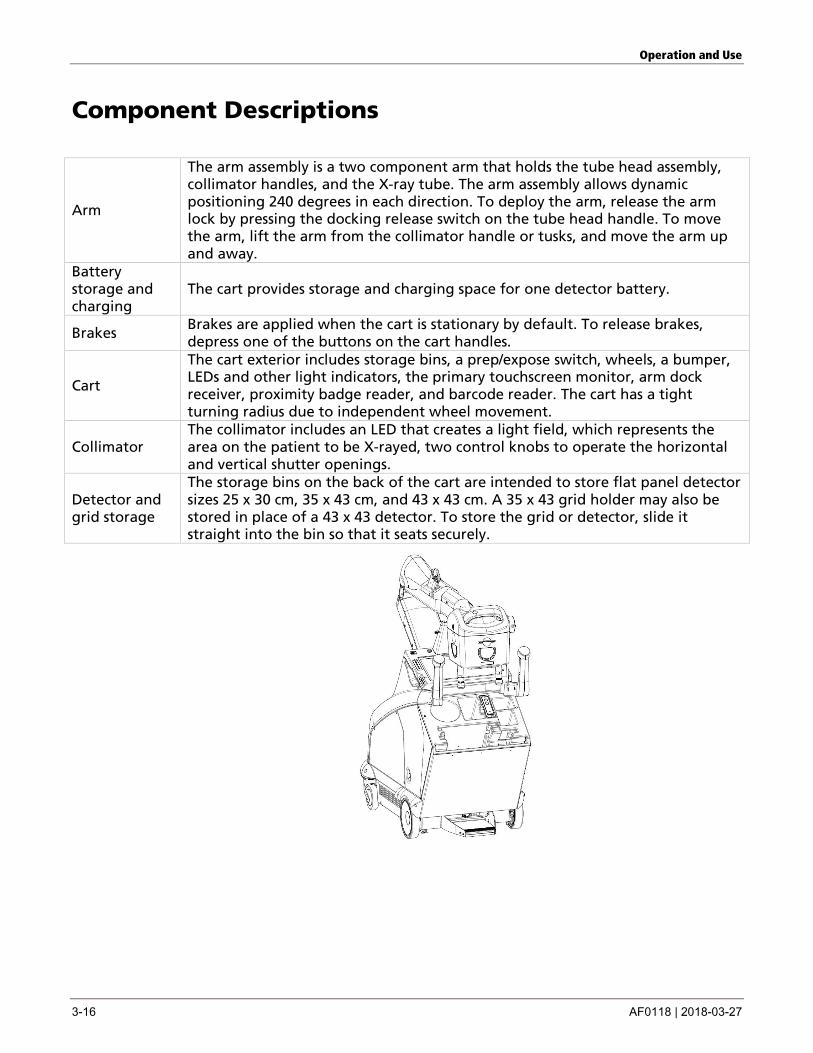
Component Descriptions
Arm
The arm assembly is a two component arm that holds the tube head assembly, collimator handles, and the X-ray tube. The arm assembly allows dynamic positioning 240 degrees in each direction. To deploy the arm, release the arm lock by pressing the docking release switch on the tube head handle. To move the arm, lift the arm from the collimator handle or tusks, and move the arm up and away.
Battery storage and charging
The cart provides storage and charging space for one detector battery.
Brakes Brakes are applied when the cart is stationary by default. To release brakes, depress one of the buttons on the cart handles.
Cart
The cart exterior includes storage bins, a prep/expose switch, wheels, a bumper, LEDs and other light indicators, the primary touchscreen monitor, arm dock receiver, proximity badge reader, and barcode reader. The cart has a tight turning radius due to independent wheel movement.
Collimator The collimator includes an LED that creates a light field, which represents the area on the patient to be X-rayed, two control knobs to operate the horizontal and vertical shutter openings.
Detector and grid storage
The storage bins on the back of the cart are intended to store flat panel detector sizes 25 x 30 cm, 35 x 43 cm, and 43 x 43 cm. A 35 x 43 grid holder may also be stored in place of a 43 x 43 detector. To store the grid or detector, slide it straight into the bin so that it seats securely.
Operation and Use
AF0118 | 2018-03-27 3-17
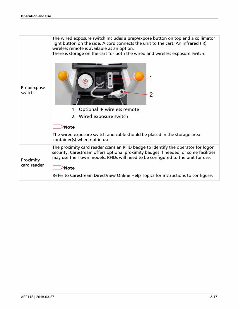
Prep/expose switch
The wired exposure switch includes a prep/expose button on top and a collimator light button on the side. A cord connects the unit to the cart. An infrared (IR) wireless remote is available as an option. There is storage on the cart for both the wired and wireless exposure switch.
1. Optional IR wireless remote
2. Wired exposure switch
Note
The wired exposure switch and cable should be placed in the storage area container(s) when not in use.
Proximity card reader
The proximity card reader scans an RFID badge to identify the operator for logon security. Carestream offers optional proximity badges if needed, or some facilities may use their own models. RFIDs will need to be configured to the unit for use.
Note
Refer to Carestream DirectView Online Help Topics for instructions to configure.
Operation and Use
3-18 AF0118 | 2018-03-27
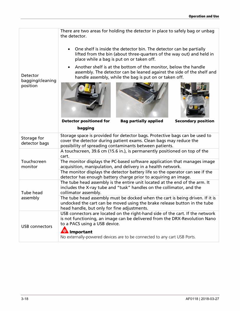
Detector bagging/cleaning position
There are two areas for holding the detector in place to safely bag or unbag the detector.
• One shelf is inside the detector bin. The detector can be partially lifted from the bin (about three-quarters of the way out) and held in place while a bag is put on or taken off.
• Another shelf is at the bottom of the monitor, below the handle assembly. The detector can be leaned against the side of the shelf and handle assembly, while the bag is put on or taken off.
Detector positioned for
bagging
Bag partially applied Secondary position
Storage for detector bags
Storage space is provided for detector bags. Protective bags can be used to cover the detector during patient exams. Clean bags may reduce the possibility of spreading contaminants between patients.
Touchscreen monitor
A touchscreen, 39.6 cm (15.6 in.), is permanently positioned on top of the cart. The monitor displays the PC-based software application that manages image acquisition, manipulation, and delivery in a health network. The monitor displays the detector battery life so the operator can see if the detector has enough battery charge prior to acquiring an image.
Tube head assembly
The tube head assembly is the entire unit located at the end of the arm. It includes the X-ray tube and “tusk” handles on the collimator, and the collimator assembly. The tube head assembly must be docked when the cart is being driven. If it is undocked the cart can be moved using the brake release button in the tube head handle, but only for fine adjustments.
USB connectors
USB connectors are located on the right-hand side of the cart. If the network is not functioning, an image can be delivered from the DRX-Revolution Nano to a PACS using a USB device.
Important No externally-powered devices are to be connected to any cart USB Ports.
Operation and Use
AF0118 | 2018-03-27 3-19
Wheels
There are two rear braked wheels and two front caster wheels. The rear wheels are braked in normal operation. The brakes are released by means of switches in the cart handles to allow movement. A manual release handle releases rear wheel braking when power is not available.
X-ray Tube
Maximum Anode Heat Content = 300 kHU Normal operation of the DRX-Revolution Nano Mobile X-ray System is considered to be 60 exposures in a 24-hour period. The tube has an IEC focal spot range from 0.9 mm to 1.9 mm equivalent at 0.1 mm increments. The smaller focal spot sizes allows better image detail for smaller patients/anatomy. Focal spot sizes are preset by the technique and are not selectable by the user.
Other Optionally supports DAP with automatic population.

AF0118 | 2018-03-27 4-1
4 Operating the System
This chapter includes basic directions for driving the cart, docking and deploying the arm, and logging on and off.
Caution
The System is not suitable for use in the presence of flammable anesthetics or a mixture of flammable anesthetics with air, nitrous oxide, or oxygen concentrations above 25% at one atmosphere (14.7 psi) or partial pressures above 27.5 kPa (4 psi).
Drive the Cart
Start
Caution
If the power cord cannot be retracted, do not drive the cart, and call for service to replace.
Caution
If the power cord is damaged in any way, do not use the cart and call for service to replace.
Caution
Do not drive the cart with the arm deployed except to enable fine patient positioning as unintended arm movement may pose a risk.
Squeeze the cart handle brake switch(es) and push or pull the cart.
The cart can be moved when arm is deployed using the brake release button on the collimator handle, but only to enable fine patient positioning.
Stop Release the brake release button(s). Go forward or reverse
Two-handed driving: With both hands on either side of the cart handles, release the brakes and gently push or pull the cart.
Turn right or left
To turn right, apply more pressure to the left side of the drive handle with your left hand, and less pressure with your right hand. To turn left, do the opposite.
Control speed
The cart is designed to travel at walking speed and is controlled by the operator.
Operating the System
4-2 AF0118 | 2018-03-27
Dock and Deploy the Arm Dock Fully compress the arm, align the arm latch over the dock receiver, and lower the
arm until it locks in place. Deploy To release the arm lock and raise the arm from the receiver, press the arm lock
release button on the tube head handle.
Operating the Machine
Start up Log in
This step assumes that the cart has been parked and docked and has been plugged into a wall socket to recharge the batteries.
1. Carefully remove the power cord from the wall socket by holding the plug housing and pulling it from the power outlet. Tug slightly on the cord and slowly release it to start the rewind mechanism. Do not pull on the cord to remove it from the wall.
2. Touch the monitor screen on the cart assembly. The system “wakes up” and the Logon screen is displayed.*
3. To log in, either enter your user name and password on the display or swipe your ID badge over the proximity reader. **
Note The system can be operated while the operator is wearing standard hospital gloves.
Shut down Log off
1. When you have completed your exams, dock the arm and return the cart to its parking/recharging location.
2. Grab the plug at the cart and gently pull out enough of the power cord to place the plug fully into an AC voltage wall socket without stretching or pulling on the cord.
3. After a predetermined time, the system automatically enters a screen saver mode, power is cut to the monitor light, and you will be automatically logged out.
Note You will remain logged in until another radiographer logs in or until you are automatically logged out by the system.
*If you swipe your badge while the monitor is still asleep, it will log you into the system and wake up the monitor. In this case, there is no need to wake up the monitor in order to log in.
**If you disconnect the power cable, it may wake up the monitor. In this case, there is no need to touch the screen.

Operating the System
AF0118 | 2018-03-27 4-3
Power Button Operation The system uses a “soft-off” style power button, which may operate differently than other Carestream products. Pressing the power button to shut down the system will put the system into a standby, low-power consumption state. Mains battery charging and brake release using the buttons on the handles remain available in standby.
Put the system into standby mode using the power button
When the system is ON, press and release the power button to put the system into standby mode.
Note This will disable detector battery charging.
Start up the system using the power button
When the system is OFF, press and release the power button to start up the system.
Re-boot the system using the power button
When the system is ON, press and hold the power button down for at least four seconds.
Note
Before performing the system reboot using the power button, attempt to reboot the system using the Quick Menu in DirectView.

AF0118 | 2018-03-27 5-1
5 Maintenance and Safety Information
Cleaning Instructions This chapter contains hardware cleaning instructions, Cautions, and maintenance information from Carestream Health. For complete information concerning Safety and Regulatory issues, see the DRX-Revolution Nano Mobile X-ray System Safety and Regulatory Information, which accompanies the publications for your system.
With Each Occurrence of Patient Contact To ensure that the DRX-Revolution Nano Mobile X-ray System continues to provide quality performance, periodically clean the exterior.
Caution
Do not spray cleaning solution directly onto the equipment. Moisten a cloth with a 70% isopropyl alcohol solution and apply top patient contact areas after each contact.
Caution
Isopropyl alcohol is a flammable solvent. Read and follow instruction in the Material Safety Data Sheet (MSDS).
Caution
Do not use a flammable spray to clean the machine. If gas from the spray comes into contact with hot electrical components, fire or electrical shock may result.
Caution
Do not use isopropyl alcohol when the machine is running, as it is a flammable liquid. If this is a concern keep in mind that batteries always retain a charge.
Important Do not let any liquid drip into the cart or its components.
If spray cleaner is used, spray the cleaning material on a cleaning cloth, and then use the cloth to clean the machine.
Maintenance and Safety Information
5-2 AF0118 | 2018-03-27
Caution
Do not use cleaning agents like ammonia. These may degrade or discolor the unit.
Caution
Do not use a regular vacuum cleaner as it generates static electricity that can damage the unit. You can use a battery powered vacuum on the exterior except for the touchscreen monitor.
Follow the instructions for cleaning each of these components:
• Monitors
• Detector
• Plastic components
• Arm assembly
Cleaning the Monitor A touchscreen monitor is a prime target for dust, fingerprints, and bacteria. At the same time, a touchscreen monitor is very sensitive, so proper cleaning is important to maximize its performance and prolong its life.
Important Do not spray any liquids onto the screen directly, press gently while cleaning, and do not use a paper towel as it may cause scratches.
Important Power down the system before cleaning the monitor. Press the system off button momentarily to enter the system standby mode.
Maintenance and Safety Information
AF0118 | 2018-03-27 5-3
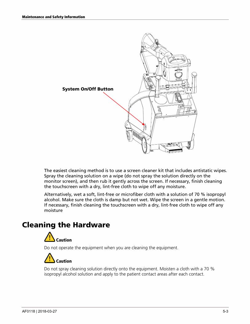
System On/Off Button
The easiest cleaning method is to use a screen cleaner kit that includes antistatic wipes. Spray the cleaning solution on a wipe (do not spray the solution directly on the monitor screen), and then rub it gently across the screen. If necessary, finish cleaning the touchscreen with a dry, lint-free cloth to wipe off any moisture.
Alternatively, wet a soft, lint-free or microfiber cloth with a solution of 70 % isopropyl alcohol. Make sure the cloth is damp but not wet. Wipe the screen in a gentle motion. If necessary, finish cleaning the touchscreen with a dry, lint-free cloth to wipe off any moisture
Cleaning the Hardware
Caution
Do not operate the equipment when you are cleaning the equipment.
Caution
Do not spray cleaning solution directly onto the equipment. Moisten a cloth with a 70 % isopropyl alcohol solution and apply to the patient contact areas after each contact.
Maintenance and Safety Information
5-4 AF0118 | 2018-03-27
Caution
Do not immerse the equipment in liquid.
Cleaning the Detector • Refer to the documentation accompanying the detector for information on
cleaning the detector or detector battery wall.
Cleaning the Plastic Components Most of the DRX-Revolution Nano Mobile X-ray System exterior is plastic and painted carbon fiber.
Important Turn off the power to the cart before cleaning.
Caution
Do not attempt to clean inside the machine or to remove any panels.
Caution
Do not use aerosol sprays directly on or over the machine.
Never use abrasive cleaning products such as abrasive sponges, steel wool pads, abrasive powdered cleaners, or harsh detergents. Plastic surfaces are easily scratched. This can ruin the finish. Do not use glass cleaner on plastic. While the damage may not be immediately visible, over time, glass cleaners will leave the plastic with an appearance that doesn't appear to be clean. Instead, use sponges, soft cloths, and mild detergents when cleaning plastic.
With a damp, lint-free cloth or an electrostatic dust cloth, wipe the panels, handle, bins, knobs, and wheels. When moistening a cloth, it is best to use a solution of 70% isopropyl alcohol. You can also use lint-free foam swabs moistened with rubbing alcohol or water for wiping hard-to-reach areas. Finish cleaning with a dry, lint-free cloth to wipe off any moisture.
Maintenance and Safety Information
AF0118 | 2018-03-27 5-5
Cleaning the Arm Handle the painted arm assembly with care to avoid striking any object, which may chip the paint.
You can clean the arm using any of these methods:
Use a battery-powered vacuum with a soft nozzle to remove the dust and dirt. Pay particular attention to corners and side grooves, where build-up of dirt and residue can occur.
Wipe the surface with a soft, lint-free cloth dampened with warm water and a mild liquid detergent. Tri sodium phosphate (TSP) is made specifically to remove grease and grime from painted surfaces without harming the finish.
Use a solution of 70% isopropyl alcohol on a clean, soft cloth.
System Maintenance
Caution
Do not attempt mechanical or electrical repair of the System. Contact your authorized Service Provider if any unit does not perform to your satisfaction.
Avoid performance issues and unplanned downtime with regularly scheduled inspection, calibration, and preventive maintenance checks. The equipment must be maintained in good operating order at all times to provide safe conditions for operating personnel and patients. It must also be maintained to prevent possible loss of patient or image data. To ensure continued safe performance of X-ray equipment, it is the owner's responsibility to supply or arrange for a periodic maintenance program.
Important After installation, perform maintenance on the system per the schedule.
Circuit diagrams and other specific instruction required to service and repair this unit is provided with Manufacturer’s service training.
Important If the unit has been out of operation for over 6 months, contact your authorized Service provider to recommission the system.
Caution
There are no parts of this equipment that can be serviced or maintained while in use with the patient.
Maintenance and Safety Information
5-6 AF0118 | 2018-03-27
Caution
No system service or maintenance can be conducted whilst the unit is in use with a patient.
Important The power cord can be replaced by an authorized service provider.
Periodically or as needed Clean the equipment. Recalibrate the touchscreen. See "Calibrate the Touchscreen" in DirectView Online Help Topics for information about calibrating the primary monitor.
Reporting Unusual Conditions Report any unusual noise, difficulty of motion, squeaks, malfunctions, or other problems with the equipment immediately. To facilitate repair if a failure occurs, provide specific information to the service representative. Note any unusual events prior to the failure, the type of procedure in progress, and specific failure information.
Replacing the Batteries The cart batteries will need to be replaced periodically dependant on usage and charging patterns. The period is expected to be between two and five years.
Caution
Cart batteries should only be replaced by an adequately-trained field engineer. Incorrect replacement could pose a hazard.
In the European Union, this symbol indicates that when the last user wishes to discard this product, it must be sent to appropriate facilities for recovery and recycling.
See http://recycle.carestreamhealth.com for additional information on the collection and recovery programs available for this product programs available for this product.
Maintenance and Safety Information
AF0118 | 2018-03-27 5-7
Caution
This product contains lead. Disposal of components that contain these materials are regulated due to environmental conditions. For disposal or recycling information, contact your local authorities.
Caution
The flat panel display in this system contains mercury. Disposal is regulated due to environmental considerations. Return the equipment to the manufacturer for proper disposal.
For recycling and disposal options in the European Union, visit the European Portable Battery Association (EPBA) web site at http://www.epbaeurope.net/. In other areas, contact local or regional solid waste authorities for recycling/disposal guidance.
Important
Contact your authorized Service Provider for service and replacement.
General Safety Information
Caution
This product contains lead. Disposal of components that contain these materials are regulated due to environmental conditions. For disposal or recycling information, contact your local authorities.
Caution
Do not make any modifications to this machine. Doing so may result in personal injury or damage to the machine.
DANGER:
USE OF CONTROLS OR ADJUSTMENTS, OR PERFORMING PROCEDURES OTHER THAN THOSE SPECIFIED, MAY RESULT IN HAZARDOUS RADIATION EXPOSURE.
DANGER:
CHARGE ONLY IN A WELL VENTILATED AREA.
Caution
Do not use a flammable spray around the machine. If gas from the spray comes in contact with hot electrical components, fire or electrical shock may result.
Maintenance and Safety Information
5-8 AF0118 | 2018-03-27
Caution
Do not use a flammable spray around the machine. If gas from the spray comes in contact with hot electrical components, fire or electrical shock may result.
Caution
Do not place a vessel that contains water or other liquid on the machine. If liquid spills into the machine, unplug the power cord if it is connected. If spilled liquid comes into contact with hot electrical components, fire or electrical shock may result.
Caution
If a thunderstorm begins, unplug the power cord in order to prevent electrical shock and fire due to a lightning strike. The user can operate the cart during a thunderstorm as long as the unit is indoors, and not plugged in.
Caution
To keep foreign matter from getting on the machine, place a cover loosely over it when not in use. Do not cover the vent holes on the head lock shroud.
Caution
Be sure to connect the power cord only to a power outlet that meets the specified voltage and current requirements. Also make certain the outlet is properly grounded. For power supply requirements, see “Chapter 6 Technical Specifications”.
Caution
Do not store the machine in areas that are poorly ventilated, damp, humid, very dusty, exposed to direct sunlight, or subject to extreme temperature or humidity changes.
Caution
Do not use the machine on an unstable surface, or one that is inclined more than 5 °. Install the machine only on a surface that can withstand the weight of the machine.
Caution
Carestream Health is responsible for the effect on basic safety, reliability and performance of the DRX-Revolution Nano Mobile X-ray System only if:
• appropriately trained personnel carry out assembly operations, extensions, readjustments, modifications or repairs;
• the electrical installation of the relevant room complies with the appropriate requirements; and
• the ME (Medical Electrical) EQUIPMENT or ME (Medical Electrical) SYSTEM is used in accordance with the instructions for use
Maintenance and Safety Information
AF0118 | 2018-03-27 5-9
Caution
Use of this equipment adjacent to other equipment should be avoided because it could result in improper operation. If such use is necessary, this equipment and the other equipment should be observed to verify that they are operating normally.
Caution
Portable RF communication equipment (including peripherals such as antenna cables and external antennas) should be used no closer than 30 cm (12 in.) to any part of the DRX-Revolution Nano Mobile X-ray System, including cables specified by the manufacturer. Otherwise, degradation of the performance of this equipment could result.

AF0118 | 2018-03-27 6-1
6 Technical Specifications
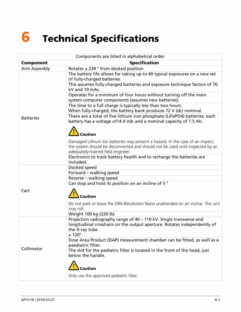
Components are listed in alphabetical order. Component Specification Arm Assembly Rotates ± 239 ° from docked position
Batteries
The battery life allows for taking up to 40 typical exposures on a new set of fully-charged batteries. This assumes fully-charged batteries and exposure technique factors of 70 kV and 10 mAs. Operates for a minimum of four hours without turning off the main system computer components (assumes new batteries). The time to a full charge is typically less than two hours. When fully-charged, the battery bank produces 72 V (dc) nominal. There are a total of five lithium iron phosphate (LiFePO4) batteries; each battery has a voltage of14.4 Vdc and a nominal capacity of 7.5 Ah.
Caution
Damaged Lithium Ion batteries may present a hazard. In the case of an impact, the system should be disconnected and should not be used until inspected by an adequately-trained field engineer. Electronics to track battery health and to recharge the batteries are included.
Cart
Docked speed Forward – walking speed Reverse – walking speed Can stop and hold its position on an incline of 5 °
Caution
Do not park or leave the DRX-Revolution Nano unattended on an incline. The unit may roll. Weight 100 kg (220 lb)
Collimator
Projection radiography range of 40 – 110 kV. Single transverse and longitudinal crosshairs on the output aperture. Rotates independently of the X-ray tube ± 120°. Dose Area Product (DAP) measurement chamber can be fitted, as well as a paediatric filter. The slot for the pediatric filter is located in the front of the head, just below the handle.
Caution
Only use the approved pediatric filter.
Technical Specifications
6-2 AF0118 | 2018-03-27
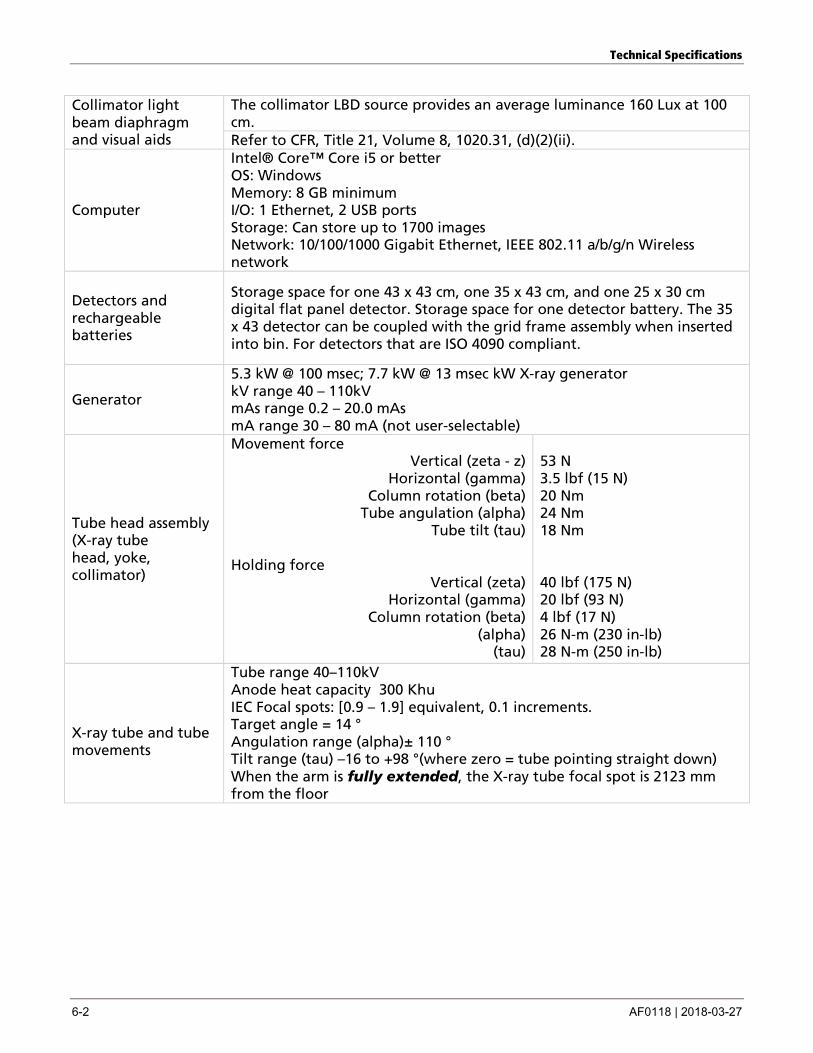
Collimator light beam diaphragm and visual aids
The collimator LBD source provides an average luminance 160 Lux at 100 cm. Refer to CFR, Title 21, Volume 8, 1020.31, (d)(2)(ii).
Computer
Intel® Core™ Core i5 or better OS: Windows Memory: 8 GB minimum I/O: 1 Ethernet, 2 USB ports Storage: Can store up to 1700 images Network: 10/100/1000 Gigabit Ethernet, IEEE 802.11 a/b/g/n Wireless network
Detectors and rechargeable batteries
Storage space for one 43 x 43 cm, one 35 x 43 cm, and one 25 x 30 cm digital flat panel detector. Storage space for one detector battery. The 35 x 43 detector can be coupled with the grid frame assembly when inserted into bin. For detectors that are ISO 4090 compliant.
Generator
5.3 kW @ 100 msec; 7.7 kW @ 13 msec kW X-ray generator kV range 40 – 110kV mAs range 0.2 – 20.0 mAs mA range 30 – 80 mA (not user-selectable)
Tube head assembly (X-ray tube head, yoke, collimator)
Movement force Vertical (zeta - z)
Horizontal (gamma) Column rotation (beta)
Tube angulation (alpha) Tube tilt (tau)
Holding force
Vertical (zeta) Horizontal (gamma)
Column rotation (beta) (alpha)
(tau)
53 N 3.5 lbf (15 N) 20 Nm 24 Nm 18 Nm 40 lbf (175 N) 20 lbf (93 N) 4 lbf (17 N) 26 N-m (230 in-lb) 28 N-m (250 in-lb)
X-ray tube and tube movements
Tube range 40–110kV Anode heat capacity 300 Khu IEC Focal spots: [0.9 – 1.9] equivalent, 0.1 increments. Target angle = 14 ° Angulation range (alpha)± 110 ° Tilt range (tau) –16 to +98 °(where zero = tube pointing straight down) When the arm is fully extended, the X-ray tube focal spot is 2123 mm from the floor
AF0118 | 2018-03-27 7-1
7 Troubleshooting
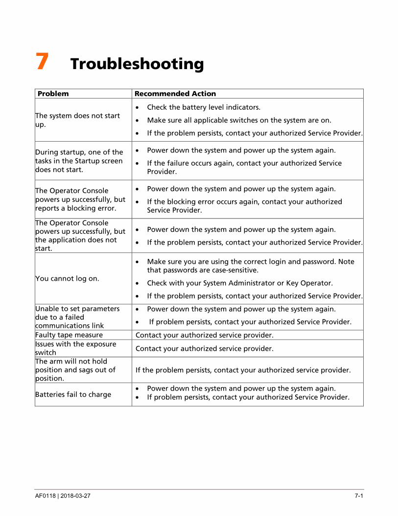
Problem Recommended Action
The system does not start up.
• Check the battery level indicators.
• Make sure all applicable switches on the system are on.
• If the problem persists, contact your authorized Service Provider.
During startup, one of the tasks in the Startup screen does not start.
• Power down the system and power up the system again.
• If the failure occurs again, contact your authorized Service Provider.
The Operator Console powers up successfully, but reports a blocking error.
• Power down the system and power up the system again.
• If the blocking error occurs again, contact your authorized Service Provider.
The Operator Console powers up successfully, but the application does not start.
• Power down the system and power up the system again.
• If the problem persists, contact your authorized Service Provider.
You cannot log on.
• Make sure you are using the correct login and password. Note that passwords are case-sensitive.
• Check with your System Administrator or Key Operator.
• If the problem persists, contact your authorized Service Provider.
Unable to set parameters due to a failed communications link
• Power down the system and power up the system again.
• If problem persists, contact your authorized Service Provider.
Faulty tape measure Contact your authorized service provider. Issues with the exposure switch Contact your authorized service provider.
The arm will not hold position and sags out of position.
If the problem persists, contact your authorized service provider.
Batteries fail to charge • Power down the system and power up the system again. • If problem persists, contact your authorized Service Provider.
Troubleshooting
7-2 AF0118 | 2018-03-27
Service and Support For technical support in the United States and Canada, contact the Center of Excellence (COE) at 1-800-328-2910. For regions outside the United States and Canada, contact your local Shared Service Center (SSC).
General Customer Support for U.S. and Canada:
Carestream Health, Inc.
150 Verona Street
Rochester, NY, USA 14608
1-800-431-7278
Elsewhere in the world, contact Carestream Health, Inc. in your country.
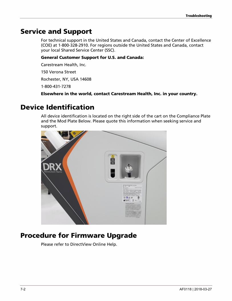
Device Identification All device identification is located on the right side of the cart on the Compliance Plate and the Mod Plate Below. Please quote this information when seeking service and support.
Procedure for Firmware Upgrade Please refer to DirectView Online Help.
AF0118 | 2018-03-27 8-1
8 Appendix A
Optional Parts
Dose Area Product (DAP)
DAP is available as an option DRX-Revolution Nano Mobile X-ray System. The DAP is configured and calibrated via the monitor display for the use of a DAP measurement chamber and additional filters. The X-ray tube will support DAP with automatic population. DAP meter specifications are the following:
Measurement Specification Upper limit of Response Range 0.8 nC/cGy-cm2 Saturation 98% at 400 V, 1 Gy/s Energy Range 40 – 150 kV Energy Dependence 5% over the 40–110 kV range Chamber Filter Effect 0.20 mm A1 (70 kV) 0.25 mm A1 (70 kV)
Wireless infrared remote exposure switch
The X-ray tube will support an optional infrared wireless exposure switch. See the User Guide for Remote Exposure Switches for Mobile X-ray Systems for instructions on using this tool.
RFID Badge Reader
See DirectView Online Help Topics.

AF0118 | 2018-03-27 1
Publication History
Version Date Changes
A 2017-02-10 Approved but not released
B 2017-12-18 • Changed document format
• Updated information throughout
C 2018-01-22 Made minor corrections to address several technical and grammatical errors
D 2018-03-27 Updated Indications for Use to specify that the system should not be used for mammography
Carestream Health, Inc.
150 Verona Street
Rochester, NY, USA 14608
© Carestream Health, Inc., 2018
Made in USA.
CARESTREAM is a trademark of Carestream Health.
Pub. No. AF0118
Rev. D