Embed Size (px)
Citation preview

DRX-Revolution Mobile X-ray System
Hardware Guide
PN 9J02382012-02-29Version 4.0


i
Table of Contents
1 Overview
Preface.............................................................................................................................................................1-1About this Guide.........................................................................................................................................1-1Related Documentation..............................................................................................................................1-1
2 Introduction to the DRX-Revolution Mobile X-ray System
Overview of the System.....................................................................................................................................2-1Description ................................................................................................................................................2-1Features .....................................................................................................................................................2-1Intended Audience .....................................................................................................................................2-2Usability .....................................................................................................................................................2-2Training .....................................................................................................................................................2-2
Safe Operation Precautions ..............................................................................................................................2-2Environmental Requirements ...........................................................................................................................2-3Acoustic Noise Emission...................................................................................................................................2-3Product Classification.......................................................................................................................................2-3
3 Parts Diagrams
Cart ..................................................................................................................................................................3-2Cart (continued)..............................................................................................................................................3-3Crane ...............................................................................................................................................................3-4Tube Head Assembly ........................................................................................................................................3-5Primary and Secondary Monitors .....................................................................................................................3-6Movements of the Boom, Column, Turntable, and Tube Head Assembly ...........................................................3-7Subcomponents ...............................................................................................................................................3-8
Boom Docking Mechanism ........................................................................................................................3-8Power Display Indicators ...........................................................................................................................3-9
Wireless Prep/Expose Switch..............................................................................................................3-10Brake Release on Boom Handle.........................................................................................................3-10
USB, Network, and Tether Connectors......................................................................................................3-11
4 Component Descriptions
5 Operating the Machine
Drive the Cart ...................................................................................................................................................5-1Dock and Undock the Boom ......................................................................................................................5-1
Start up the Cart and Log In or Shut Down the Cart and Log Out.......................................................................5-2

-ii
6 Maintenance and Safety Information
Cleaning Instructions ....................................................................................................................................... 6-1With Each Occurrence of Patient Contact ................................................................................................... 6-1Cleaning the Monitors ................................................................................................................................ 6-2Cleaning the Hardware............................................................................................................................... 6-2
Cleaning the Detector:.......................................................................................................................... 6-3Cleaning the Battery Footprint .............................................................................................................. 6-3
Cleaning the Plastic Components................................................................................................................ 6-3Basic Rules for Cleaning Plastic ........................................................................................................... 6-3
Cleaning the Metal Column ........................................................................................................................ 6-3System Maintenance......................................................................................................................................... 6-4
Semi-Annually ............................................................................................................................................ 6-4Periodically or as Needed .......................................................................................................................... 6-4Reporting Unusual Conditions.................................................................................................................... 6-4Replacing the Batteries .............................................................................................................................. 6-5Disposal..................................................................................................................................................... 6-5
Additional Safety Information ........................................................................................................................... 6-6Cautions and Warnings .............................................................................................................................. 6-6
7 Technical Specifications
Components..................................................................................................................................................... 7-1
8 Troubleshooting
Service and Support ............................................................................................................................. 8-2
Appendix A
Optional Parts .................................................................................................................................................. A-1Optional Tools for the DRX-Revolution ...................................................................................................... A-12-D Barcode Reader .................................................................................................................................. A-1Anti-scatter Grid......................................................................................................................................... A-1Dose Area Product ..................................................................................................................................... A-1Selected Service Diagnostic Tools .............................................................................................................. A-2Wireless remote exposure switch............................................................................................................... A-2
Appendix B
Hardware-Software Interfaces ..........................................................................................................................B-1Logon Screen .............................................................................................................................................B-1Emergency Stop .........................................................................................................................................B-2Screen Saver ..............................................................................................................................................B-2Log out at Either Monitor...........................................................................................................................B-2Detector/Grid Holder Battery Indicator ......................................................................................................B-3Cart Battery Indicator.................................................................................................................................B-3

iii
Table of Contents
Drive Mode ................................................................................................................................................B-3Tube and Grid Alignment System (Option).................................................................................................B-4
Grid Alignment Screen .........................................................................................................................B-5Grid Alignment Procedure....................................................................................................................B-6Procedure............................................................................................................................................B-7
Overview
9J0238 1-1
1 Overview
PrefaceThe information contained herein is based on the experience and knowledge relating to the subject matter gained by Carestream Health, Inc. prior to publication. No patent license is granted by this information. Carestream Health reserves the right to change this information without notice and makes no warranty, express or implied, with respect to this information. Carestream Health shall not be liable for any loss or damage, including consequential or special damages, resulting from the use of this information, even if loss or damage is caused by negligence or other fault of Carestream Health.
About this Guide This guide uses Note, Important, and Caution messages to emphasize information or potential risks to personnel or equipment.
NOTE: Notes provide additional information, such as expanded explanations, hints, or reminders.
IMPORTANT: An Important message highlights critical policy information that affects how you use this manual and this product.
CAUTION:Cautions point out procedures that you must follow precisely to avoid injury to yourself, others, damage to the system or any of its components, loss of data, or corruption of files in software applications. Disregarding the caution statement may lead to abnormal use.
Related Documentation
• DRX-Revolution Safety and Regulatory Information
• DRX-Revolution Online Help
• DRX-Revolution User Release Notes
Introduction to the DRX-Revolution Mobile X-ray System
9J0238 2-1
2 Introduction to the DRX-Revolution Mobile X-ray System
Overview of the SystemThe DRX-Revolution System Mobile X-ray system is designed specifically for Digital Radiography (DR) with the CARESTREAM DRX-1 System detector, or with other wireless flat-panel detectors. The DRX-Revolution incorporates the tools required for acquiring medical diagnostic images outside of a standard X-ray room.
The DRX-Revolution is an all inclusive mobile X-ray system, providing:
• A high power 32 kW generator
• State-of-the-art drive system for movement and maneuverability
• User-friendly X-ray tube positioning in five axes of motion
• The industry's first telescoping column for better visibility while driving
• Storage for detectors and supplies
• Carestream's proven user interface and image processing tools
Description The compact size of the DRX-Revolution allows patient treatment in many areas of a hospital including the operating room, emergency department, and intensive care units. It moves on many kinds of surfaces and can fit in elevators and maneuver in close proximity to a patient from many angles. Its collapsible column allows visibility while it is being driven down busy hospital corridors. The cart moves so a technologist can walk behind it, steering and controlling its speed while traveling from one location to another. Software is accessed from a primary monitor on the cart and a secondary monitor on the tube head.
Features The DRX-Revolution allows radiographic exams of patients who cannot be transported to an X-ray room. The tube head assembly can be moved in any direction: horizontal, vertical, tilted, angulated, and rotated. It has storage space for equipment and supplies. An optional barcode scanner provides quick identification of patient wristbands, forms, and orders. All of these hardware features and options are described in this guide.

2-2
Introduction to the DRX-Revolution Mobile X-ray System
Intended Audience The audience for this guide includes technologists, radiologists, service engineers, and quality assurance technicians.
Usability The design and development of this diagnostic X-ray system incorporated a usability engineering process in accordance with IEC 60601-1-6: Medical Electrical Equipment, Part 1-6: General requirements for safety. Collateral Standard: Usability.
Training This equipment is intended for use by appropriately educated and skilled radiological health care professionals who have received specific training on the operation and use of this equipment.
Only qualified, trained X-ray personnel should operate the System. Operation of the equipment by persons who have not been trained or who are unfamiliar with the functions and controls of the System may cause serious injury to the patient, serious injury to the operator, or equipment damage.
Safe Operation PrecautionsPersonnel operating and maintaining this equipment should be familiar with all aspects of operation and maintenance. To ensure safety, read the DRX-Revolution Safety and Regulatory Information carefully before using the system and observe all Cautions, Importants, and Notes located throughout the manual.
IMPORTANT: For continued safe use of this equipment, follow the instructions contained in this operating manual.
IMPORTANT: Study this manual carefully before using the equipment and keep it at hand for quick reference.
The equipment must be used only by qualified personnel and only after training in the specific operations. It is the operator's responsibility to ensure the patient's safety by visual observation, audio communication, proper patient positioning, and use of the protective devices.
Thoroughly check that there is no interference or possibility of collision between the patient and other equipment.
Maintain the equipment periodically to ensure continued safe use of the equipment. See “Chapter 6 Maintenance and Safety Information” for periodic maintenance recommendations.
The equipment must be repaired only by authorized service personnel.
For more information, see the DRX-Revolution Safety and Regulatory Information.

Introduction to the DRX-Revolution Mobile X-ray System
2-3
Environmental RequirementsThis equipment and all components will perform to specifications when operated in normal use under the least favorable combination of the following temperature, humidity, and altitude specifications.
Acoustic Noise EmissionThe sound pressure level is less than 70 db.
Product ClassificationProduct classification per IEC 60601-1,
Class I equipment/Internally powered.
Environment
Relative Humidity (non-condensing)
In-Use: 30– 65 %
non-condensing
Storage: 10–86 %
non-condensing
The receiving and storage areas must be dry and able to provide the proper humidity and temperature control required for the equipment.
Atmospheric Pressure 70–106 kPa 70–106 kPa
Temperature In-Use: 18 to 30 °C
(64 to 86 °F)
Storage:–20 to 55 °C
(–4 to131 °F)
Altitude Equivalent to maximum 3,048 m atmospheric pressure.
Parts Diagrams
9J0238 3-1
3 Parts Diagrams
While most of the external parts will be intuitive to an experienced radiographer, please review the parts diagrams in this guide so you become familiar with the naming conventions used by Carestream Health, which are standardized throughout all of the documentation.
For a part's description, see “Chapter 4 Component Descriptions”.
For a part's specifications, see “Chapter 7 Technical Specifications”.
For a list of optional parts or features, see “ Optional Parts“ in Appendix A.
3-2 9J0238
Parts Diagrams
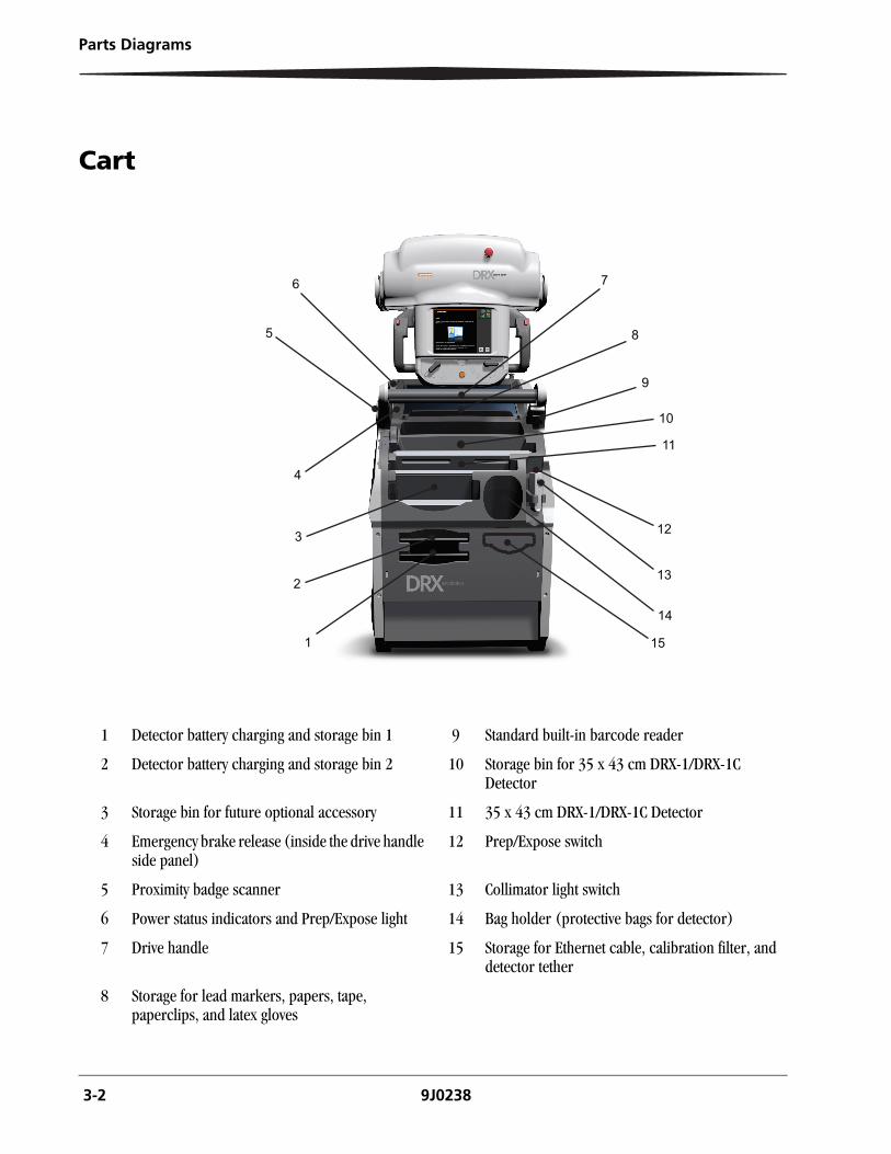
Cart
1 Detector battery charging and storage bin 1 9 Standard built-in barcode reader
2 Detector battery charging and storage bin 2 10 Storage bin for 35 x 43 cm DRX-1/DRX-1C Detector
3 Storage bin for future optional accessory 11 35 x 43 cm DRX-1/DRX-1C Detector
4 Emergency brake release (inside the drive handle side panel)
12 Prep/Expose switch
5 Proximity badge scanner 13 Collimator light switch
6 Power status indicators and Prep/Expose light 14 Bag holder (protective bags for detector)
7 Drive handle 15 Storage for Ethernet cable, calibration filter, and detector tether
8 Storage for lead markers, papers, tape, paperclips, and latex gloves
1
2
3
4
5
6 7
8
9
10
11
12
13
15
14

Parts Diagrams
9J0238 3-3
Cart (continued)
1 Primary monitor display
2 Retractable AC voltage power cord
3 Bumper sensor
4 Front caster (2)
5 AC voltage circuit breaker. The DC voltage circuit breaker is in the same location on the opposite side.
6 Motorized drive wheel (2)
7 Drive handle side panel
8 Barcode reader
9 Boom dock receiver
10 Emergency stop (2)
11 Base for wireless prep/expose switch (optional)
3-4 9J0238
Parts Diagrams
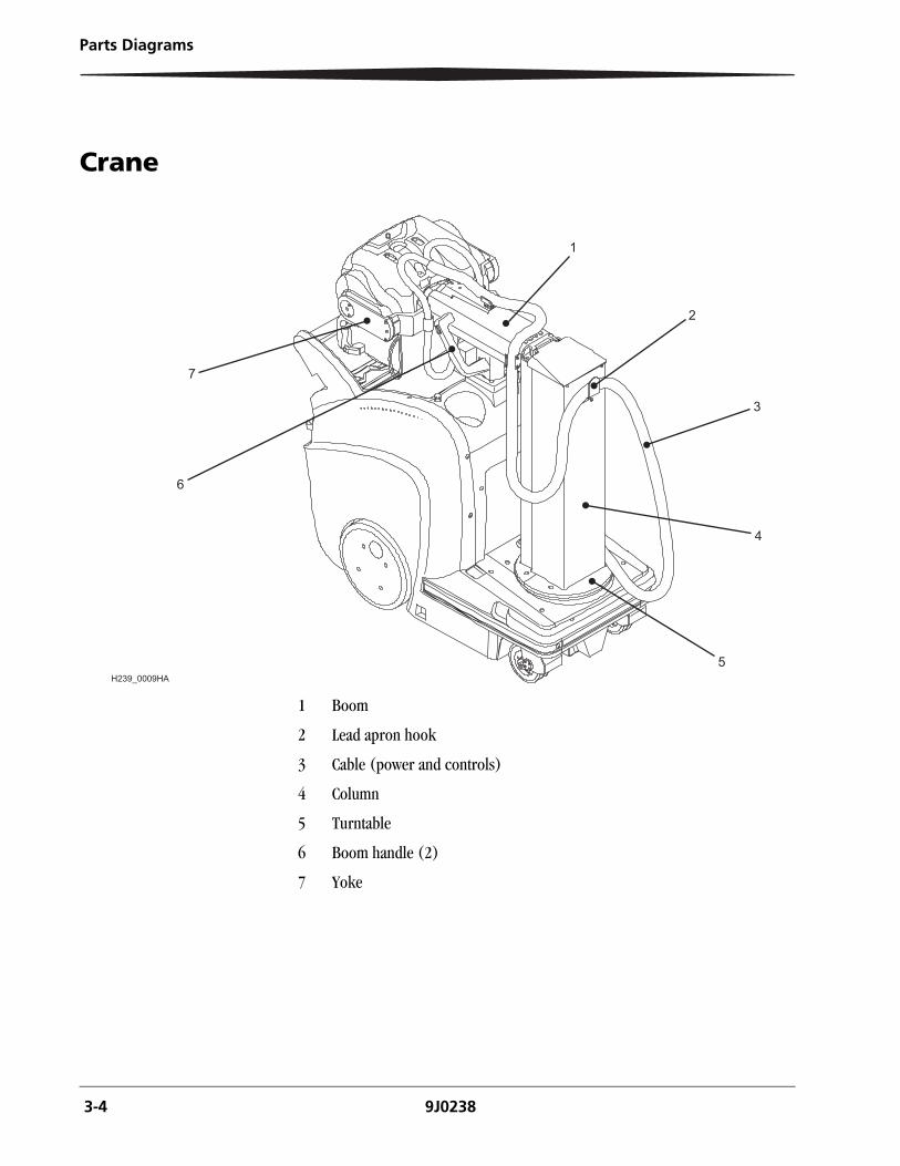
Crane
1 Boom
2 Lead apron hook
3 Cable (power and controls)
4 Column
5 Turntable
6 Boom handle (2)
7 Yoke
1
2
3
4
5
6
7
H239_0009HA
Parts Diagrams
9J0238 3-5
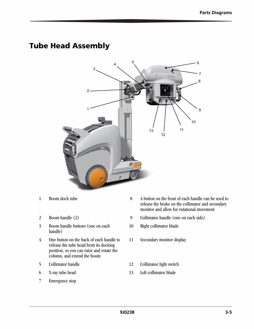
Tube Head Assembly
1 Boom dock tube 8 A button on the front of each handle can be used to release the brake on the collimator and secondary monitor and allow for rotational movement
2 Boom handle (2) 9 Collimator handle (one on each side)
3 Boom handle buttons (one on each handle)
10 Right collimator blade
4 One button on the back of each handle to release the tube head from its docking position, so you can raise and rotate the column, and extend the boom
11 Secondary monitor display
5 Collimator handle 12 Collimator light switch
6 X-ray tube head 13 Left collimator blade
7 Emergency stop
1
2
34 5 6
7
8
9
10
1112
13
3-6 9J0238
Parts Diagrams
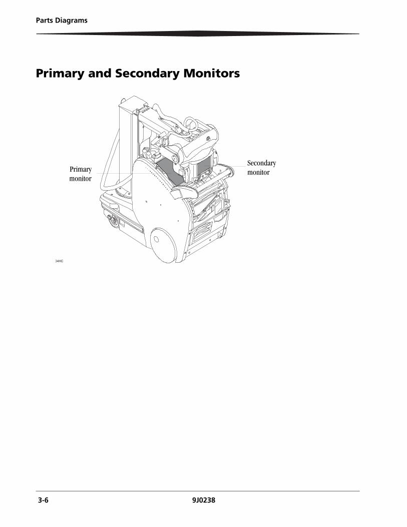
Primary and Secondary Monitors
04HC
Secondary monitorPrimary
monitor
Parts Diagrams
9J0238 3-7
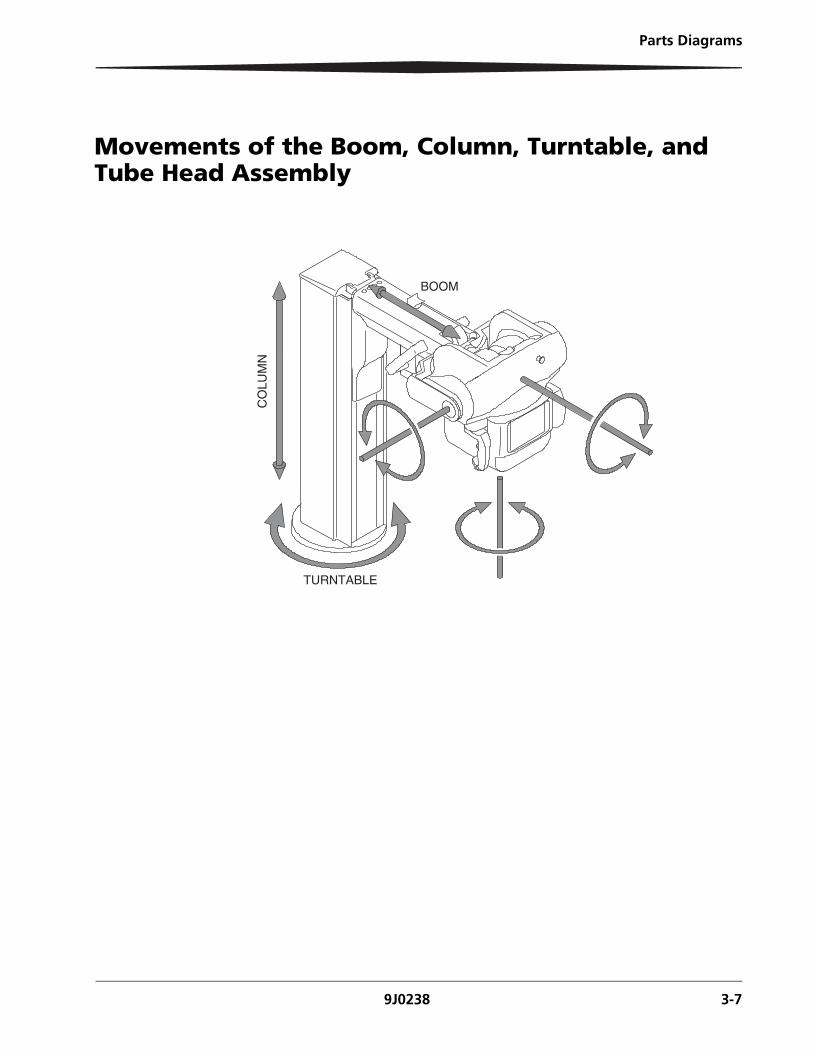
Movements of the Boom, Column, Turntable, and Tube Head Assembly
TURNTABLE
BOOM
CO
LUM
N
3-8 9J0238
Parts Diagrams
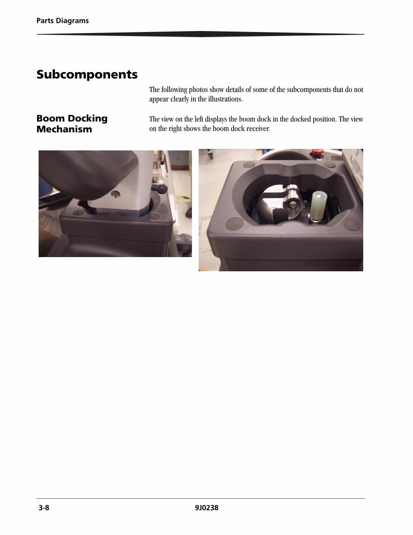
SubcomponentsThe following photos show details of some of the subcomponents that do not appear clearly in the illustrations.
Boom Docking Mechanism
The view on the left displays the boom dock in the docked position. The view on the right shows the boom dock receiver.
Parts Diagrams
9J0238 3-9
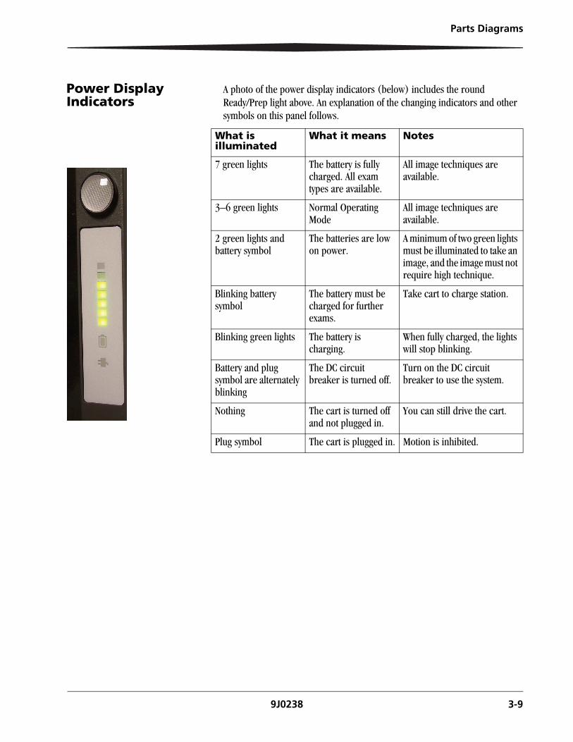
Power Display Indicators
A photo of the power display indicators (below) includes the round Ready/Prep light above. An explanation of the changing indicators and other symbols on this panel follows.
What is illuminated
What it means Notes
7 green lights The battery is fully charged. All exam types are available.
All image techniques are available.
3–6 green lights Normal Operating Mode
All image techniques are available.
2 green lights and battery symbol
The batteries are low on power.
A minimum of two green lights must be illuminated to take an image, and the image must not require high technique.
Blinking battery symbol
The battery must be charged for further exams.
Take cart to charge station.
Blinking green lights The battery is charging.
When fully charged, the lights will stop blinking.
Battery and plug symbol are alternately blinking
The DC circuit breaker is turned off.
Turn on the DC circuit breaker to use the system.
Nothing The cart is turned off and not plugged in.
You can still drive the cart.
Plug symbol The cart is plugged in. Motion is inhibited.
3-10 9J0238
Parts Diagrams
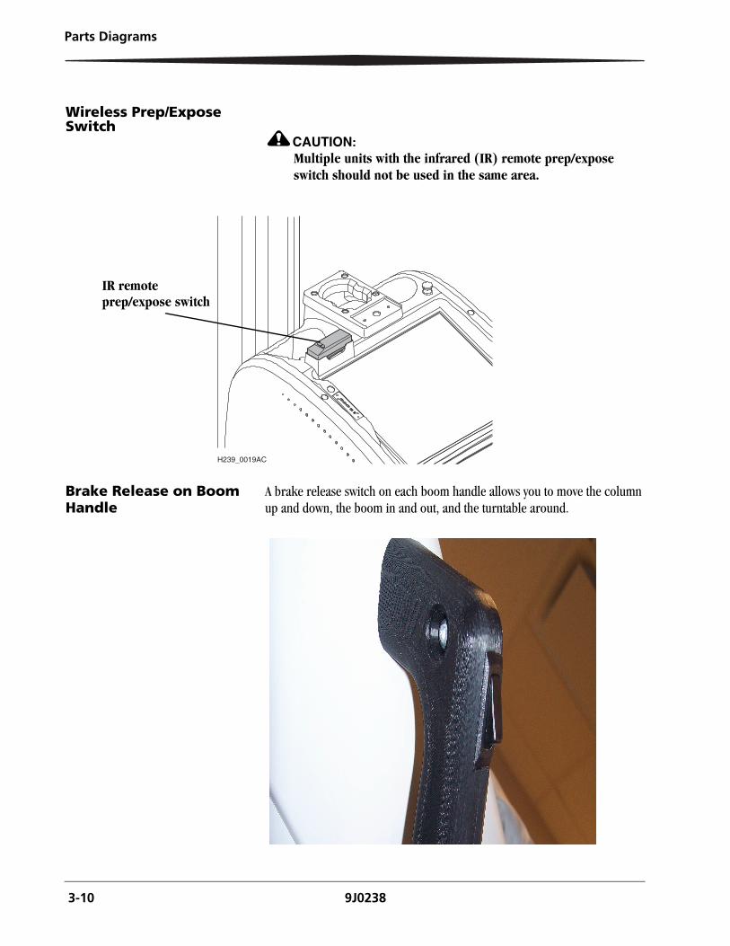
Wireless Prep/Expose Switch
CAUTION:Multiple units with the infrared (IR) remote prep/expose switch should not be used in the same area.
Brake Release on Boom Handle
A brake release switch on each boom handle allows you to move the column up and down, the boom in and out, and the turntable around.
H239_0019AC
IR remote prep/expose switch
Parts Diagrams
9J0238 3-11
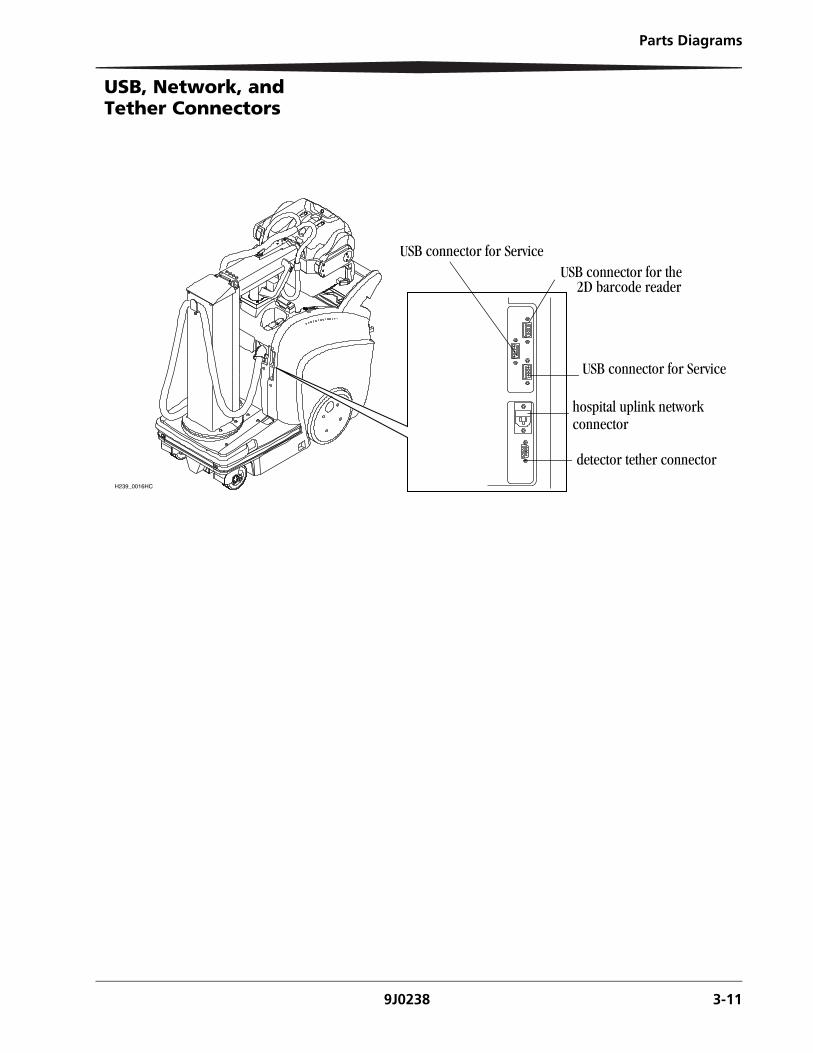
USB, Network, and Tether Connectors
H239_0016HC
USB connector for ServiceUSB connector for the
USB connector for Service
hospital uplink network connector
detector tether connector
2D barcode reader
Component Descriptions
9J0238 4-1
4 Component Descriptions
Components are listed alphabetically.
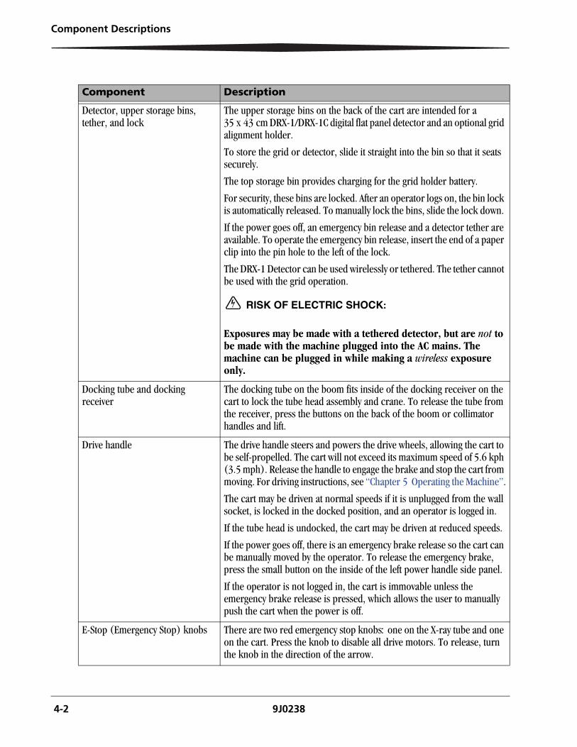
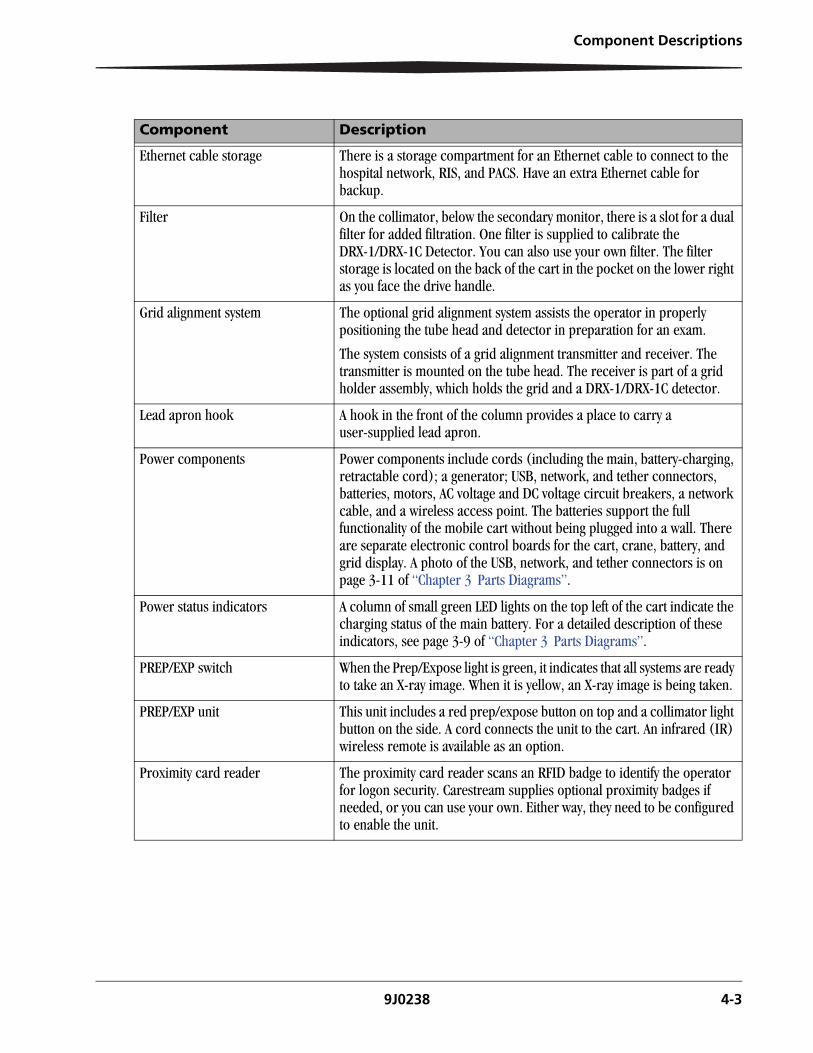
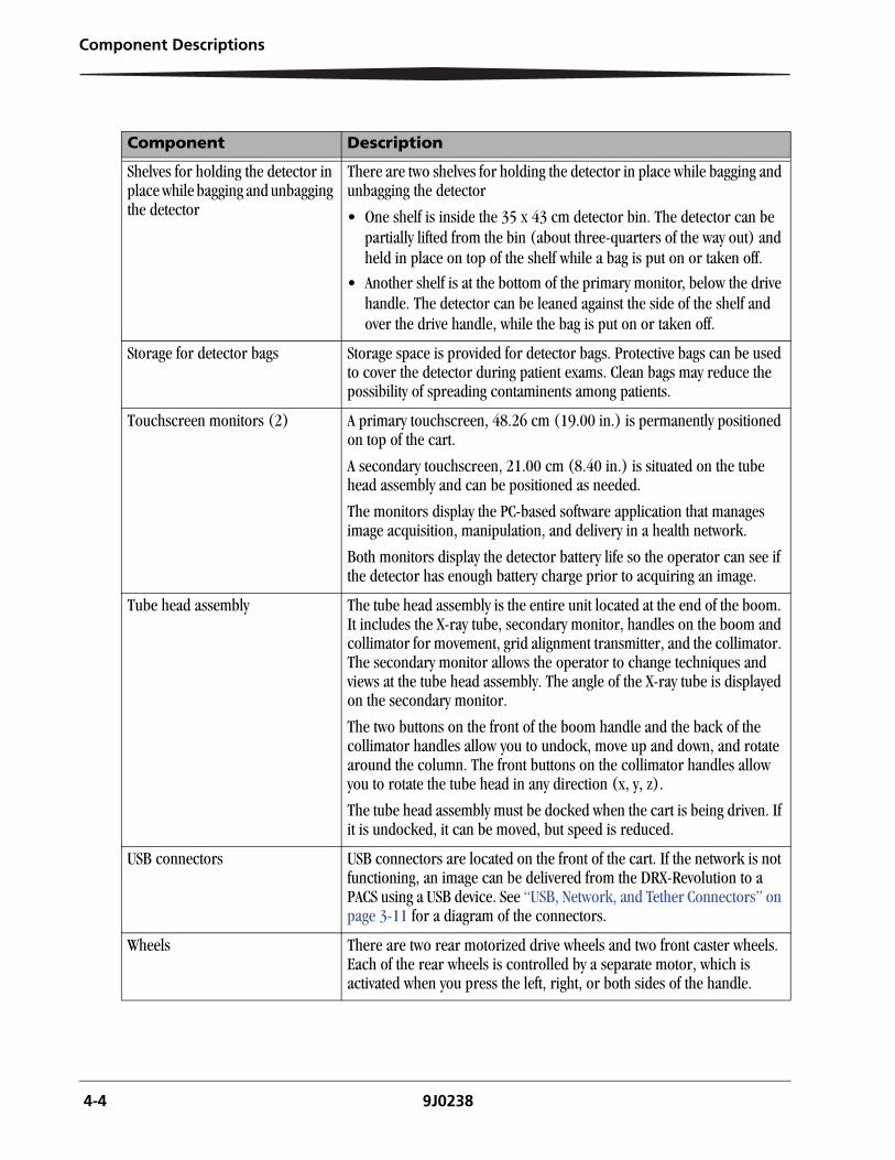
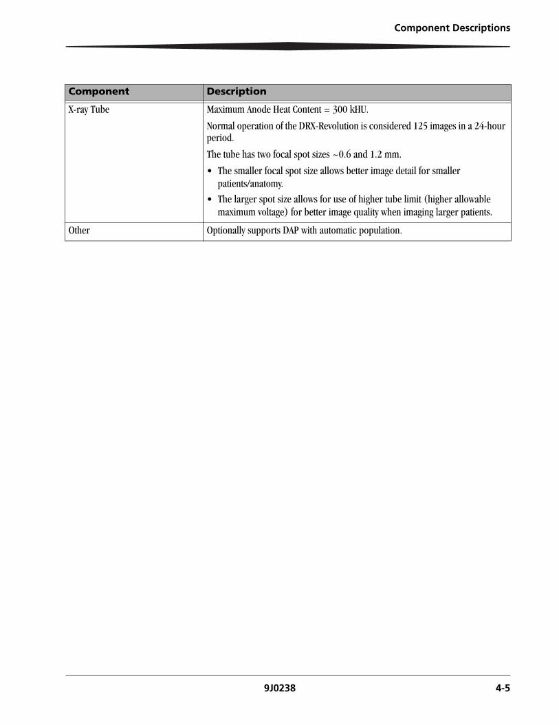
Component Description
Battery storage and charging The cart provides storage and charging space for two DRX batteries.
Bins Storage bins are located in the back of the cart. See Detector.
Boom The boom is an extendable, horizontal arm that holds the tube head assembly, two boom handles, and the boom dock tube.
Brakes See: Bumper, Column, Drive handle, E-Stop.
Bumper The bumper on the front of cart is touch sensitive. Forward motion is prevented when the bumper touches an obstacle. Reverse drive the cart to release the bumper brake.
Cart The cart exterior includes a drive handle, detector, storage bins, prep/expose switch, wheels, bumper, LEDs and other light indicators, primary touchscreen monitor, boom dock receiver, proximity badge reader, and barcode reader. The cart has a zero degree pivoting radius. Inside, the cart contains batteries, a generator, circuitry, and motors.
Collimator The collimator includes an LED that creates a light field, which represents the area on the patient to be X-rayed, two control knobs to operate the horizontal and vertical shutter openings, and a collimator brake release.
Column The column is an extendable, motor-assisted, vertical component that lifts and lowers the boom. The column rotates right or left on a turntable 270 ° in each direction. To release the brake and raise the column or extend the boom, grip either or both of the collimator handles, or either boom handle, press and hold the button on the back of the handle(s), and lift or pull.
Connectors See: Power components.
Crane The crane includes the turntable, column, and boom.
4-2 9J0238
Component Descriptions
Component Description
Detector, upper storage bins, tether, and lock
The upper storage bins on the back of the cart are intended for a 35 x 43 cm DRX-1/DRX-1C digital flat panel detector and an optional grid alignment holder.
To store the grid or detector, slide it straight into the bin so that it seats securely.
The top storage bin provides charging for the grid holder battery.
For security, these bins are locked. After an operator logs on, the bin lock is automatically released. To manually lock the bins, slide the lock down.
If the power goes off, an emergency bin release and a detector tether are available. To operate the emergency bin release, insert the end of a paper clip into the pin hole to the left of the lock.
The DRX-1 Detector can be used wirelessly or tethered. The tether cannot be used with the grid operation.
RISK OF ELECTRIC SHOCK:
Exposures may be made with a tethered detector, but are not to be made with the machine plugged into the AC mains. The machine can be plugged in while making a wireless exposure only.
Docking tube and docking receiver
The docking tube on the boom fits inside of the docking receiver on the cart to lock the tube head assembly and crane. To release the tube from the receiver, press the buttons on the back of the boom or collimator handles and lift.
Drive handle The drive handle steers and powers the drive wheels, allowing the cart to be self-propelled. The cart will not exceed its maximum speed of 5.6 kph (3.5 mph). Release the handle to engage the brake and stop the cart from moving. For driving instructions, see “Chapter 5 Operating the Machine”.
The cart may be driven at normal speeds if it is unplugged from the wall socket, is locked in the docked position, and an operator is logged in.
If the tube head is undocked, the cart may be driven at reduced speeds.
If the power goes off, there is an emergency brake release so the cart can be manually moved by the operator. To release the emergency brake, press the small button on the inside of the left power handle side panel.
If the operator is not logged in, the cart is immovable unless the emergency brake release is pressed, which allows the user to manually push the cart when the power is off.
E-Stop (Emergency Stop) knobs There are two red emergency stop knobsone on the X-ray tube andone on the cart. Press the knob to disable all drive motors. To release, turn the knob in the direction of the arrow.
Component Descriptions
9J0238 4-3
Ethernet cable storage There is a storage compartment for an Ethernet cable to connect to the hospital network, RIS, and PACS. Have an extra Ethernet cable for backup.
Filter On the collimator, below the secondary monitor, there is a slot for a dual filter for added filtration. One filter is supplied to calibrate the DRX-1/DRX-1C Detector. You can also use your own filter. The filter storage is located on the back of the cart in the pocket on the lower right as you face the drive handle.
Grid alignment system The optional grid alignment system assists the operator in properly positioning the tube head and detector in preparation for an exam.
The system consists of a grid alignment transmitter and receiver. The transmitter is mounted on the tube head. The receiver is part of a grid holder assembly, which holds the grid and a DRX-1/DRX-1C detector.
Lead apron hook A hook in the front of the column provides a place to carry a user-supplied lead apron.
Power components Power components include cords (including the main, battery-charging, retractable cord); a generator; USB, network, and tether connectors, batteries, motors, AC voltage and DC voltage circuit breakers, a network cable, and a wireless access point. The batteries support the full functionality of the mobile cart without being plugged into a wall. There are separate electronic control boards for the cart, crane, battery, and grid display. A photo of the USB, network, and tether connectors is on page 3-11 of “Chapter 3 Parts Diagrams”.
Power status indicators A column of small green LED lights on the top left of the cart indicate the charging status of the main battery. For a detailed description of these indicators, see page 3-9 of “Chapter 3 Parts Diagrams”.
PREP/EXP switch When the Prep/Expose light is green, it indicates that all systems are ready to take an X-ray image. When it is yellow, an X-ray image is being taken.
PREP/EXP unit This unit includes a red prep/expose button on top and a collimator light button on the side. A cord connects the unit to the cart. An infrared (IR) wireless remote is available as an option.
Proximity card reader The proximity card reader scans an RFID badge to identify the operator for logon security. Carestream supplies optional proximity badges if needed, or you can use your own. Either way, they need to be configured to enable the unit.
Component Description
4-4 9J0238
Component Descriptions
Shelves for holding the detector in place while bagging and unbagging the detector
There are two shelves for holding the detector in place while bagging and unbagging the detector
• One shelf is inside the 35 x 43 cm detector bin. The detector can be partially lifted from the bin (about three-quarters of the way out) and held in place on top of the shelf while a bag is put on or taken off.
• Another shelf is at the bottom of the primary monitor, below the drive handle. The detector can be leaned against the side of the shelf and over the drive handle, while the bag is put on or taken off.
Storage for detector bags Storage space is provided for detector bags. Protective bags can be used to cover the detector during patient exams. Clean bags may reduce the possibility of spreading contaminents among patients.
Touchscreen monitors (2) A primary touchscreen, 48.26 cm (19.00 in.) is permanently positioned on top of the cart.
A secondary touchscreen, 21.00 cm (8.40 in.) is situated on the tube head assembly and can be positioned as needed.
The monitors display the PC-based software application that manages image acquisition, manipulation, and delivery in a health network.
Both monitors display the detector battery life so the operator can see if the detector has enough battery charge prior to acquiring an image.
Tube head assembly The tube head assembly is the entire unit located at the end of the boom. It includes the X-ray tube, secondary monitor, handles on the boom and collimator for movement, grid alignment transmitter, and the collimator. The secondary monitor allows the operator to change techniques and views at the tube head assembly. The angle of the X-ray tube is displayed on the secondary monitor.
The two buttons on the front of the boom handle and the back of the collimator handles allow you to undock, move up and down, and rotate around the column. The front buttons on the collimator handles allow you to rotate the tube head in any direction (x, y, z).
The tube head assembly must be docked when the cart is being driven. If it is undocked, it can be moved, but speed is reduced.
USB connectors USB connectors are located on the front of the cart. If the network is not functioning, an image can be delivered from the DRX-Revolution to a PACS using a USB device. See “USB, Network, and Tether Connectors” on page 3-11 for a diagram of the connectors.
Wheels There are two rear motorized drive wheels and two front caster wheels. Each of the rear wheels is controlled by a separate motor, which is activated when you press the left, right, or both sides of the handle.
Component Description
Component Descriptions
9J0238 4-5
Component Description
X-ray Tube Maximum Anode Heat Content = 300 kHU.
Normal operation of the DRX-Revolution is considered 125 images in a 24-hour period.
The tube has two focal spot sizes ~0.6 and 1.2 mm.
• The smaller focal spot size allows better image detail for smaller patients/anatomy.
• The larger spot size allows for use of higher tube limit (higher allowable maximum voltage) for better image quality when imaging larger patients.
Other Optionally supports DAP with automatic population.

9J0238 5-1
5 Operating the Machine
This chapter includes basic directions for driving the cart, docking and undocking the boom, and logging on and off.
Drive the Cart
Dock and Undock the Boom
Start Squeeze the drive handle and push or pull the cart. The boom must be docked in order to drive it at full speed. It can be moved when undocked, but its speed is reduced.
Stop Release the drive handle.
Go forward or reverse Two-handed driving: With both hands on either side of the drive handle, squeeze the handle and gently push or pull using the motor to power the drive wheels.One-handed driving: Squeeze the center of the drive handle and push or pull.
Turn right or left To turn right, apply more pressure to the left side of the drive handle with your left hand, and less pressure with your right hand. To turn left, do the opposite.
Control speed The cart will keep pace with your walking speed, up to 5.6 kph (3.5 mph).
Dock Fully compress the boom, align the boom dock tube over the boom dock receiver, and lower the crane until it locks in place.
IMPORTANT: Make sure the boom is fully compressed before attempting to dock.
When the tube head is docked, the display is turned off, and the Patient Work List is displayed on the secondary monitor.
Undock To release the crane lock and raise the boom dock from the receiver, press the boom brake release buttons behind the boom handle or collimator handles. The primary monitor automatically “wakes up” when the tube head is raised.
5-2 9J0238
Operating the Machine
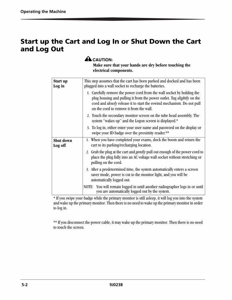
Start up the Cart and Log In or Shut Down the Cart and Log Out
CAUTION:Make sure that your hands are dry before touching the electrical components.
Start up Log in
This step assumes that the cart has been parked and docked and has been plugged into a wall socket to recharge the batteries.
1. Carefully remove the power cord from the wall socket by holding the plug housing and pulling it from the power outlet. Tug slightly on the cord and slowly release it to start the rewind mechanism. Do not pull on the cord to remove it from the wall.
2. Touch the secondary monitor screen on the tube head assembly. The system “wakes up” and the Logon screen is displayed.*
3. To log in, either enter your user name and password on the display or swipe your ID badge over the proximity reader.**
Shut down Log off
1. When you have completed your exams, dock the boom and return the cart to its parking/recharging location.
2. Grab the plug at the cart and gently pull out enough of the power cord to place the plug fully into an AC voltage wall socket without stretching or pulling on the cord.
3. After a predetermined time, the system automatically enters a screen saver mode, power is cut to the monitor light, and you will be automatically logged out.
NOTE: You will remain logged in until another radiographer logs in or until you are automatically logged out by the system.
* If you swipe your badge while the primary monitor is still asleep, it will log you into the system and wake up the primary monitor. Then there is no need to wake up the primary monitor in order to log in.
** If you disconnect the power cable, it may wake up the primary monitor. Then there is no need to touch the screen.
9J0238 6-1
6 Maintenance and Safety Information
This chapter contains hardware cleaning instructions, Cautions and maintenance information from Carestream Health. For complete information concerning Safety and Regulatory issues, see the CARESTREAM DRX-Revolution Safety and Regulatory Information that accompanies the publications for your system.
Cleaning Instructions
With Each Occurrence of Patient Contact
To ensure that the DRX-Revolution continues to provide quality performance, periodically clean the exterior.
CAUTION:Do not spray cleaning solution directly onto the equipment. Moisten a cloth with a 70 % isopropyl alcohol solution and apply to patient contact areas after each contact.
CAUTION:Isopropyl alcohol is a flammable solvent. Read and follow instructions in the Material Safety Data Sheet (MSDS)
CAUTION:Do not use a flammable spray to clean the machine. If gas from the spray comes in contact with hot electrical components, fire or electrical shock may result.
CAUTION:Do not use isopropyl alcohol when the machine is running, as it is a flammable liquid. If this is a concern, keep in mind that batteries always retain a charge.
IMPORTANT: Do not let any liquid drip into the cart or its components.
If spray cleaner is used, spray the cleaning material on a cleaning cloth, and then use the cloth to clean the machine.
Do not use volatile cleaning agents like ammonia. These may degrade or discolor the unit.
6-2 9J0238
Maintenance and Safety Information
Do not use a regular vacuum as it generates static electricity that can damage the unit. You can use a battery-powered vacuum on the exterior except for on the touchscreen monitors.
Follow the instructions for cleaning each of these components:
• Monitors
• Detector/Grid
• Plastic Components
• Metal Column
Cleaning the Monitors A touchscreen monitor is a prime target for dust, finger prints, and bacteria. At the same time, a touchscreen monitor is very sensitive, so proper cleaning is important to maximize its performance and prolong its life.
IMPORTANT: Do not spray any liquids onto the screen directly, press gently while cleaning, and do not use a paper towel as it may cause scratches.
Power down the system before cleaning the monitor.
The easiest cleaning method is to use a screen cleaner kit that includes antistatic wipes. Spray a little of the cleaning solution on a wipe, and then rub it gently across the screen. If necessary, finish cleaning the touchscreen with a dry, lint-free cloth to wipe off any moisture.
Alternatively, wet a soft, lint-free or microfiber cloth with a solution of 70 % isopropyl alcohol. Make sure the cloth is damp but not wet. Wipe the screen in a gentle motion. If necessary, finish cleaning the touchscreen with a dry, lint-free cloth to wipe off any moisture.
Cleaning the Hardware
CAUTION:Do not operate the equipment when you are cleaning the equipment.
CAUTION:Do not spray cleaning solution directly onto the equipment. Moisten a cloth with a 70 % isopropyl alcohol solution and apply to the patient contact areas after each contact.
CAUTION:Do not immerse the equipment in liquid.
Maintenance and Safety Information
9J0238 6-3
Cleaning the Detector: 1. Disconnect the detector from its power source.
a. Remove the tether.
b. Remove the battery.
2. Moisten a cloth with a 70 % isopropyl alcohol solution.
3. Apply the moistened cloth to the equipment.
Cleaning the Battery Footprint
1. Wipe the well clean of dust or debris with a soft cloth.
2. Use a brush or vacuum to clean out the prongs in the battery compartment well, or contact Service for assistance.
Cleaning the Plastic Components
Most of the DRX-Revolution exterior is plastic. All of the components except the touchscreen monitors, which are glass, the grid, and the painted metal column, are plastic.
IMPORTANT: Turn off the power to the cart before cleaning.
Do not attempt to clean inside the machine or to remove the plastic panels.
Do not use aerosol sprays directly on or over the machine.
Basic Rules for Cleaning Plastic
Never use abrasive cleaning products such as abrasive sponges, steel wool pads, abrasive powdered cleaners, or harsh detergents. Plastic surfaces are easily scratched. This can ruin the finish. Do not use glass cleaner on plastic. While the damage may not be immediately visible, over time, glass cleaners will leave the plastic with an appearance that doesn't appear to be clean. Instead, use sponges, soft cloths, and mild detergents when cleaning plastic.
With a damp, lint-free cloth or an electrostatic dust cloth, wipe the panels, handle, bins, knobs, and wheels. When moistening a cloth, it is best to use a solution of 70 % isopropyl alcohol. You can also use lint-free foam swabs moistened with rubbing alcohol or water for wiping hard-to-reach areas. Finish cleaning with a dry, lint-free cloth to wipe off any moisture.
Cleaning the Metal Column
Handle the painted metal column with care to avoid striking any object, which may chip the paint.
You can clean the column using any of these methods:
• Use a battery-powered vacuum with a soft nozzle to remove the dust and dirt. Pay particular attention to corners and side grooves, where buildup of dirt and residue can occur.
• Wash the surface with a soft, lint-free cloth dampened with warm water and a mild liquid detergent.
• Tri sodium phosphate (TSP) is made specifically to remove grease and grime from painted surfaces without harming the finish.
• Use a solution of 70 % isopropyl alcohol on a clean, soft cloth.
6-4 9J0238
Maintenance and Safety Information
System Maintenance
CAUTION:Do not attempt mechanical or electrical repair of the System. Contact your authorized Service Provider if any unit does not perform to your satisfaction.
Avoid performance issues and unplanned downtime with regularly scheduled inspection, calibration, and preventive maintenance checks. The equipment must be maintained in good operating order at all times to provide safe conditions for operating personnel and patients. It must also be maintained to prevent possible loss of patient or image data. To ensure continued safe performance of X-ray equipment, it is the owner's responsibility to supply or arrange for a periodic maintenance program. After installation, perform maintenance on the system per the schedule.
Semi-Annually Run an X-ray calibration on the Detector Array monthly or as prompted by the software. The System must be serviced and repaired only by your authorized Service Provider.
Periodically or as Needed
Clean the equipment.
Recalibrate the touchscreen. Follow the on-screen instructions for calibrating the secondary monitor. See "Calibrate the Touchscreen" in the DRX-Revolution Online Help for information about calibrating the primary monitor.
Reporting Unusual Conditions
Report any unusual noise, difficulty of motion, squeaks, malfunctions, or other problems with the equipment immediately.
To facilitate repair if a failure occurs, provide specific information to the service representative. Note any unusual events prior to the failure, the type of procedure in progress, and specific failure information.

Maintenance and Safety Information
9J0238 6-5
Replacing the Batteries
CAUTION:The cart batteries will need to be replaced every two to five years. The batteries contain lead and pose a hazard to the environment and human health if not disposed of properly. Due to the toxicity of lead, the U.S. EPA Resource Conservation and Recovery Act (RCRA) and state solid and hazardous waste authorities consider a spent lead-acid battery a regulated waste. The customer must treat this battery as a hazardous waste if it is not recycled. A recycling infrastructure is widely available in the U.S. to manage this battery type.
Disposal
In the European Union, this symbol indicates that when thelast user wishes to discard this product, it must be sent to appropriate facilities for recovery and recycling.
See http://recycle.carestreamhealth.com for additional information on the collection and recovery programs available for this product.programs available for this produc
CAUTION:This product contains lead. Disposal of components that contain these materials are regulated due to invironmental conditions. For disposal or recycling information, contact your local authorities.
CAUTION:The flat panel display in this system contains mercury. Disposal is regulated due to environmental considerations. Return the equipment to the manufacturer for proper disposal.
For recycling and disposal options in the European Union, visit the European Portable Battery Association (EPBA) web site at http://www.epbaeurope.net/. In other areas, congtact local or regional solid waste authorities for recylcling/disposal guidance.
IMPORTANT: Contact your authorized Service Provider for service and
replacement.
6-6 9J0238
Maintenance and Safety Information
Additional Safety Information
Cautions and Warnings
CAUTION:Do not make any modifications to this machine. Doing so may result in personal injury or damage to the machine.
DANGER: USE OF CONTROLS OR ADJUSTMENTS, OR PERFORMING PROCEDURES OTHER THAN THOSE SPECIFIED, MAY RESULT IN HAZARDOUS RADIATION EXPOSURE.
DANGER: CHARGE ONLY IN A WELL VENTILATED AREA.
RISK OF ELECTRIC SHOCK:Do not use a flammable spray around the machine. If gas from the spray comes in contact with hot electrical components, fire or electrical shock may result.
CAUTION:Exposures may be made with a tethered detector, but tethered exposures are NOT to be made with the machine plugged in to the AC mains. The machine can be plugged in while making a wireless exposure only.
CAUTION:Do not use a flammable spray around the machine. If gas from the spray comes in contact with hot electrical components, fire or electrical shock may result.
CAUTION:Do not place a vessel that contains water or other liquid on the machine. If liquid spills into the machine, first turn off the machine’s main power switch and then unplug the power cord.
CAUTION:If a thunderstorm begins, unplug the power cord in order to prevent electrical shock and fire due to a lightning strike. The user can operate the cart during a thunderstorm as long as the unit is indoors, and not plugged in.
CAUTION:To keep foreign matter from getting on the machine, place a cover loosely over it when not in use. Do not cover the vent holes on the sides of the panels.
Maintenance and Safety Information
9J0238 6-7
CAUTION:Be sure to connect the power cord only to a power outlet that meets the specified voltage and current requirements. Also make certain the outlet is properly grounded. For power supply requirements, see “Chapter 7 Technical Specifications”.
CAUTION:Do not store the machine in areas that are poorly ventilated, damp, humid, very dusty, exposed to direct sunlight, or subject to extreme temperature or humidity changes.
CAUTION:Do not use the machine on an unstable surface, or one that is inclined more than 5 °. Install the machine only on a surface that can withstand the weight of the machine.
9J0238 7-1
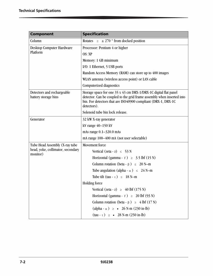
7 Technical Specifications
ComponentsComponents are listed in alphabetical order.
Component Specification
Batteries The battery life allows for driving one mile and taking 40 exposures without charging. This assumes fully charged batteries and exposure technique factors of 70 kV and 10 mAs.
Operates for a minimum of four hours without turning off the main system computer components (assumes new batteries).
When fully charged, the battery bank produces 240 V(dc) nominal.
There are a total of 20 lead-acid batteries; each battery has 12 V and 12 A capacity.
Electronics to track battery health and to recharge the batteries are included.
Cable The large cable, that extends from the front of the cart and hangs on the lead apron hook, powers and controls the tube head assembly.
Cart Docked speed (assumes new batteries)
Forward 0 to 5.6 kph (0 to 3.5 mph) ±15 %
Reverse 0 to 3.2 kph (0 to 2 mph) ±15 %
Can stop and hold its position on an incline of 7 ° (12.3 %)
Weight 567 kg (1300 lb)
Circuit breakers (2) On the left side (facing the drive handle) is a DC voltage circuit breaker. This breaker controls all DC voltage power to the PC, generator, monitor displays, motion systems, and circuit boards.
On the right side is an AC voltage circuit breaker. This breaker controls AC voltage to the cart when plugged into an outlet. The AC voltage is used only for the battery charging system. This circuit breaker has no effect when the cart is not plugged in.
Collimator Projection radiography range of 40–150 kV. Single transverse and longitudinal cross-hairs on the output aperture. Rotates independently of the x-ray tube ± 90 °. Accessory rails for the use of a Dose Area Product (DAP) measurement chamber and additional filters.
Collimator field light and visual aids
The collimator light field source provides an average luminance 160 lux at 100 cm. Refer to CFR, Title 21, Volume 8, 1020.31, (d)(2)(ii).
7-2 9J0238
Technical Specifications
Column Rotates ± 270 ° from docked position
Desktop Computer Hardware Platform
Processor: Pentium 4 or higher
OS: XP
Memory: 1 GB minimum
I/O: 1 Ethernet, 5 USB ports
Random Access Memory (RAM) can store up to 400 images
WLAN antenna (wireless access point) or LAN cable
Computerized diagnostics
Detectors and rechargeable battery storage bins
Storage space for one 35 x 43 cm DRX-1/DRX-1C digital flat panel detector. Can be coupled to the grid frame assembly when inserted into bin. For detectors that are ISO40900 compliant (DRX-1, DRX-1C detectors).
Solenoid tube bin lock release.
Generator 32 kW X-ray generator
kV range 40–150 kV
mAs range 0.1–320.0 mAs
mA range 100–400 mA (not user selectable)
Tube Head Assembly (X-ray tube head, yoke, collimator, secondary monitor)
Movement force
Vertical (zeta - z) 53 N
Horizontal (gamma - ) 3.5 lbf (15 N)
Column rotation (beta - ) 20 N–m
Tube angulation (alpha - ) 24 N–m
Tube tilt (tau - ) 18 N–m
Holding force
Vertical (zeta - z) 40 lbf (175 N)
Horizontal (gamma - ) 20 lbf (93 N)
Column rotation (beta - ) 4 lbf (17 N)
(alpha - ) 26 N-m (230 in-lb)
(tau - ) 28 N-m (250 in-lb)
Component Specification
Technical Specifications
9J0238 7-3
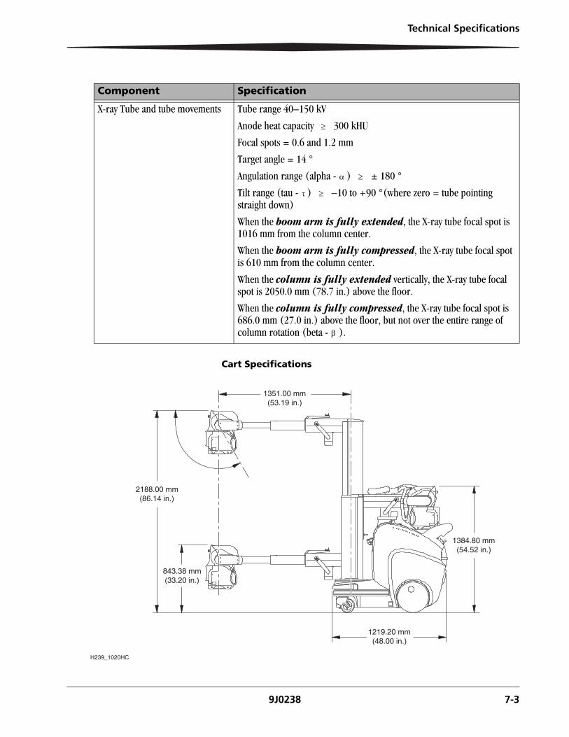
Cart Specifications
X-ray Tube and tube movements Tube range 40–150 kV
Anode heat capacity 300 kHU
Focal spots = 0.6 and 1.2 mm
Target angle = 14 °
Angulation range (alpha - ) ± 180 °
Tilt range (tau - ) –10 to +90 °(where zero = tube pointing straight down)
When the boom arm is fully extended, the X-ray tube focal spot is 1016 mm from the column center.
When the boom arm is fully compressed, the X-ray tube focal spot is 610 mm from the column center.
When the column is fully extended vertically, the X-ray tube focal spot is 2050.0 mm (78.7 in.) above the floor.
When the column is fully compressed, the X-ray tube focal spot is 686.0 mm (27.0 in.) above the floor, but not over the entire range of column rotation (beta - ).
Component Specification
2188.00 mm(86.14 in.)
843.38 mm(33.20 in.)
1351.00 mm(53.19 in.)
1384.80 mm(54.52 in.)
1219.20 mm(48.00 in.)
H239_1020HC

9J0238 8-1
8 Troubleshooting
Problem Recommended Action
The system does not start up. • Check the battery level indicators.
• Make sure all applicable switches (circuit breakers) on the system are on.
• If the problem persists, contact your authorized Service Provider.
During startup, one of the tasks in the Startup screen does not start.
• Power down the system and power up the system again.
• If the failure occurs again, contact your authorized Service Provider.
The Operator Console powers up successfully, but reports a blocking error.
• Power down the system and power up the system again.
• If the blocking error occurs again, contact your authorized Service Provider.
The Operator Console powers up successfully, but the application does not start.
• Power down the system and power up the system again.
• If the problem persists, contact your authorized Service Provider.
You cannot log on. • Make sure you are using the correct login and password. Note that passwords are case sensitive.
• Check with your System Administrator or Key Operator.
• If the problem persists, contact your authorized Service Provider.
None of the motorized movements are working.
• Check the Emergency Stop buttons in order to ensure that they are not engaged.

8-2 9J0238
Troubleshooting
Service and Support For technical support in the United States and Canada, contact the Center of Excellence (COE) at 1-800-328-2910.
For regions outside the United States and Canada, contact your local Shared Service Center (SSC).
General Customer Support for U.S. and Canada:
CARESTREAM HEALTH, INC.
150 Verona Street
Rochester, NY, 14608
United States
1-800-431-7278
Elsewhere in the world, contact Carestream Health, Inc. in your country.
9J0238 1
Appendix A
Optional Parts
Optional Tools for the DRX-Revolution
• 2-D Barcode reader
• Anti-scatter grid
• Dose Area Product (DAP)
• Selected service diagnostic tools
• Wireless infrared remote exposure switch
• X-ray tube grid alignment (includes grid and frame assembly)
2-D Barcode Reader In addition to the cart mounted barcode reader, a hand-held, two-dimensional (2D) barcode reader is available as an option.
Anti-scatter Grid Specifications for the anti-scatter grid are as follows:
• Ratio is 8:1
• Line density is 80 lines per centimeter (approx. 200 lines/in.)
• Focus distance is 110 cm (approximately 44 in.)
• Dimensions of the grid are compatible for use with a 35 x 43 cm receptor (14 x 17 in.)
• Grid lines run parallel to the short side (35 cm or 14 in.) of the grid assembly
See the DRX-Revolution Online Help for instructions on using this feature.
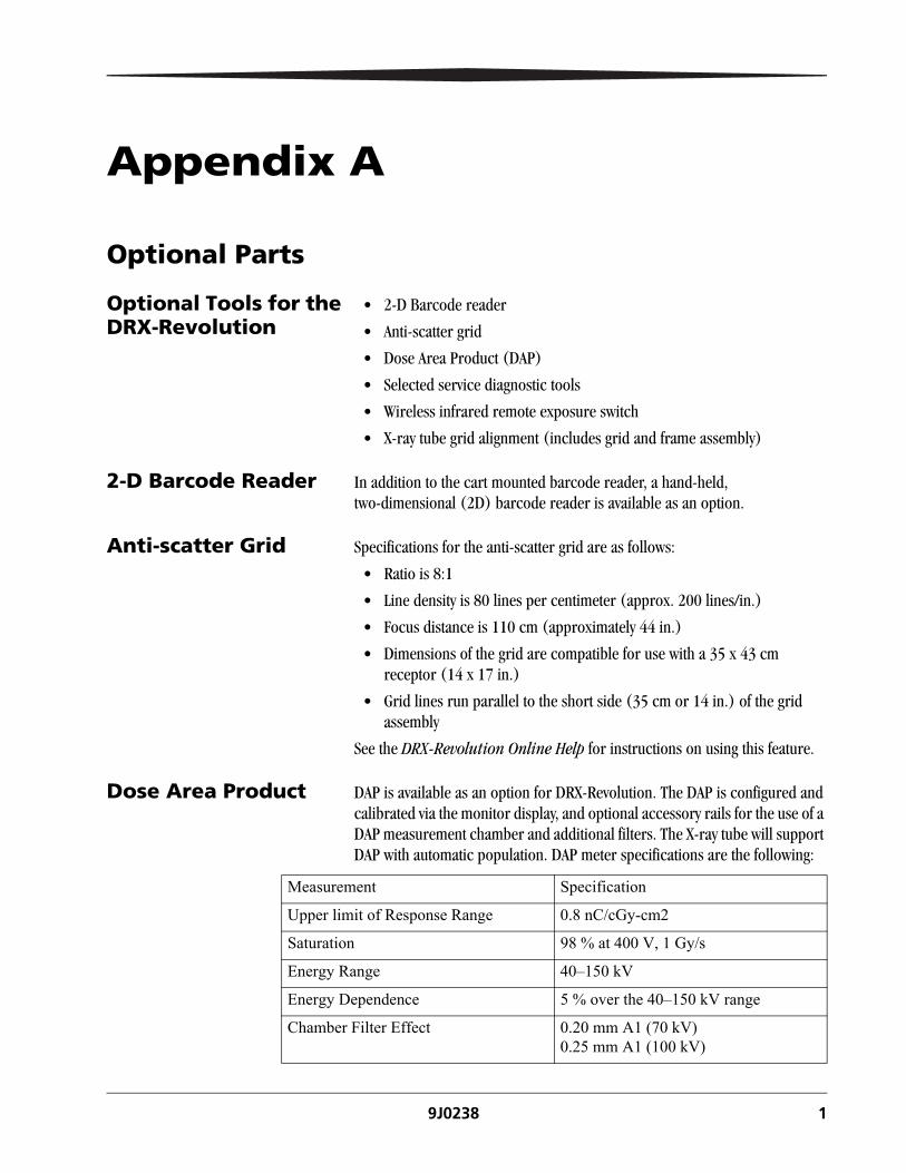
Dose Area Product DAP is available as an option for DRX-Revolution. The DAP is configured and calibrated via the monitor display, and optional accessory rails for the use of a DAP measurement chamber and additional filters. The X-ray tube will support DAP with automatic population. DAP meter specifications are the following:
Measurement Specification
Upper limit of Response Range 0.8 nC/cGy-cm2
Saturation 98 % at 400 V, 1 Gy/s
Energy Range 40–150 kV
Energy Dependence 5 % over the 40–150 kV range
Chamber Filter Effect 0.20 mm A1 (70 kV)0.25 mm A1 (100 kV)

2 9J0238
Selected Service Diagnostic Tools
See the DRX-Revolution Service Guide for instructions on using these tools.
Wireless remote exposure switch
The X-ray tube will support an optional infrared wireless exposure switch. See the DRX-Revolution Service Guide for instructions on using this tool.

9J0238 -1
Appendix B
Hardware-Software InterfacesIMPORTANT: See the Tube Head Software section of the
DRX-Revolution Online Help for information about using the Tube Head Software, and a guide to the icons displayed on the tube head screens. Go to the Primary monitor and touch the question mark in the upper right corner of the screen. Tube Head Software topics are located in the Table of Contents.
Logon Screen
To log in using your proximity badge for the first time, follow these steps. (This procedure assumes you have already have a user account.):
1. Log in as usual using the touch screen.
2. Go to the Utilities menu.
3. Touch Register Badge.
4. Scan your badge by swiping it across the badge reader, which is a small rectangle on the left side (as you face the drive handle) that protrudes about 0.5 in. from the cart below the drive handle.
5. Wait for a beep.
2 9J0238
Appendix B
6. When asked if you want to enter this change to your account, touch OK.
7. Enter your password.
8. Save your changes.
9. When asked if you want to associate the badge to your account, touch OK
Emergency Stop The Emergency Stop or E-Stop indicator is displayed on the screen if the user has activated it. The indicator will no longer be displayed when the cart begins to move again.
Screen Saver Touching either monitor and using any part of the cart, such as driving or using the prep/expose switch, will reset the Screen Saver timer and the Auto Logout timer. This prevents the system from automatically logging out a technologist while they drive to a patient’s room.
Special notes on the Screen Saver:
• To save power, the power the primary monitor is disabled when the tube head assembly is docked. You cannot see the primary monitor when the tube head is docked.
• There is no Screen Saver for the secondary monitor. Instead, the cart will cut power to the backlight on this monitor to save on battery life. The system is activated by touching the secondary monitor.
Log out at Either Monitor
A technologist may log out by touching the Log Out button on the primary or secondary monitor display.
Appendix B
9J0238 3
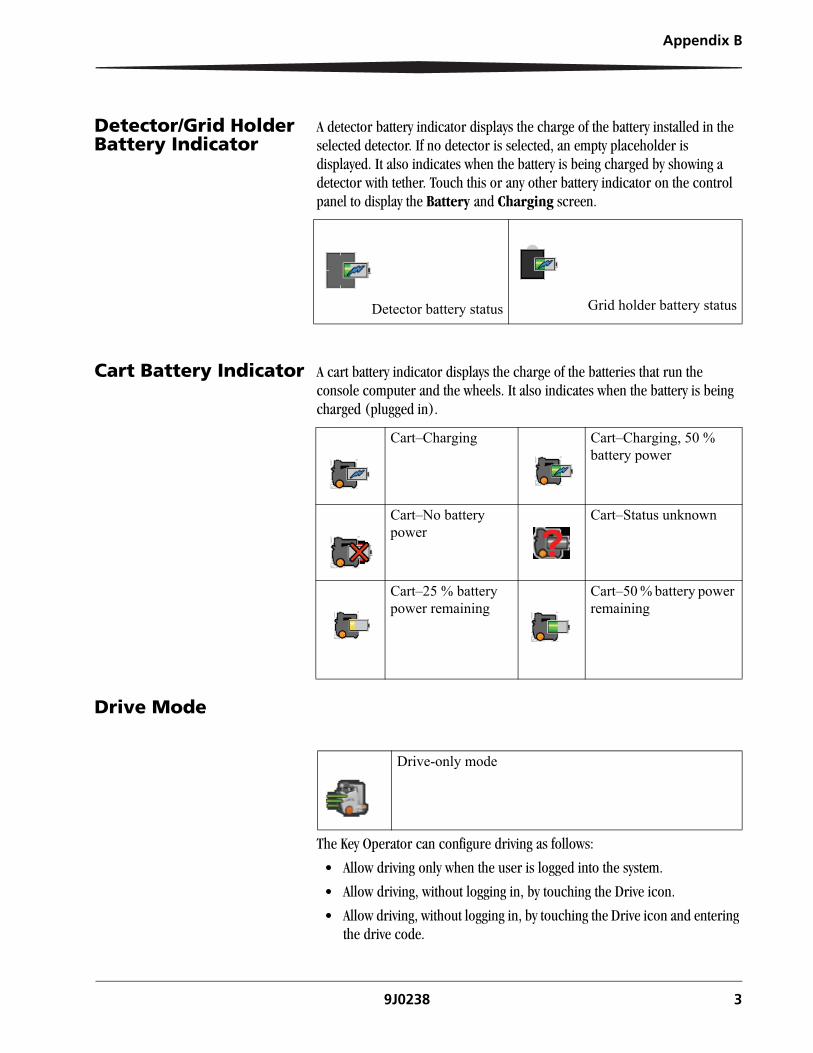
Detector/Grid Holder Battery Indicator
A detector battery indicator displays the charge of the battery installed in the selected detector. If no detector is selected, an empty placeholder is displayed. It also indicates when the battery is being charged by showing a detector with tether. Touch this or any other battery indicator on the control panel to display the Battery and Charging screen.
Cart Battery Indicator A cart battery indicator displays the charge of the batteries that run the console computer and the wheels. It also indicates when the battery is being charged (plugged in).
Drive Mode
The Key Operator can configure driving as follows:
• Allow driving only when the user is logged into the system.
• Allow driving, without logging in, by touching the Drive icon.
• Allow driving, without logging in, by touching the Drive icon and entering the drive code.
Detector battery status Grid holder battery status
Cart–Charging Cart–Charging, 50 % battery power
Cart–No battery power
Cart–Status unknown
Cart–25 % battery power remaining
Cart–50 % battery power remaining
Drive-only mode
4 9J0238
Appendix B
Tube and Grid Alignment System (Option)
The Tube and Grid Alignment System option provides a tool that assists the user to efficiently align the X-ray source to the grid/receptor for centering and perpendicularity at the correct focal distance.
The Tube and Grid Alignment System option:
• Displays the tube head and detector angles relative to gravity.
• Provides guidance for positioning the tube head assembly with three alignment indicators (vertical, horizontal, in/out) to achieve proper alignment at a selected Source to Grid Distance (SGD) (102–127 cm (40–50 in.).
• Displays the current SGD.
NOTE: Two Grid Alignment systems operating within 6.0 m (20.0 ft) of each other may cause grid alignment interference.
NOTE: The grid alignment system is optimized for use on beds that have non-metallic mattress supports in the patient chest region.
CAUTION:It is possible that cases of extreme interference might prevent the grid alignment system from functioning properly. It is always the user's responsibility to ensure proper alignment before taking an X-ray.
Appendix B
9J0238 5
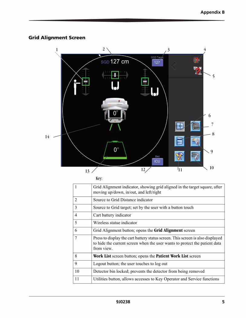
Grid Alignment Screen
Key:
5
6
14
1 4
13 11 10
7
9
8
12
2 3
1 Grid Alignment indicator, showing grid aligned in the target square, after moving up/down, in/out, and left/right
2 Source to Grid Distance indicator
3 Source to Grid target; set by the user with a button touch
4 Cart battery indicator
5 Wireless statue indicator
6 Grid Alignment button; opens the Grid Alignment screen
7 Press to display the cart battery status screen. This screen is also displayed to hide the current screen when the user wants to protect the patient data from view.
8 Work List screen button; opens the Patient Work List screen
9 Logout button; the user touches to log out
10 Detector bin locked; prevents the detector from being removed
11 Utilities button, allows accesses to Key Operator and Service functions
6 9J0238
Appendix B
Grid Alignment Procedure
Setup 1. Insert the DRX-1 System Detector into the grid frame by placing the grid holder on a flat surface, with the bottom of the detector into the bottom tray of the grid holder, and snapping the detector in place at the top.
2. Position the grid frame on top of the mattress, behind the patient anatomy.
3. Enter the Grid Alignment screen on the remote display by touching the Grid Alignment button
4. Confirm the target Source to Grid Distance (SGD), such as 102, 112, or 127 cm (40, 44, or 50 in.).
5. For optimum image processing results, choose the appropriate bed type from the Bed Type indicator, located at the bottom of the screen. Select either ED for a trauma gurney, or ICU if an intensive care unit bed is used.
6. Use the buttons on the back and front sides of the collimator handles to release the brakes and position the X-ray tube as you would for any exam. Use the tube angle and detector angle indicators, and the collimator light as guides for positioning.
NOTE: The grid alignment system is most accurate when the grid frame is positioned a minimum of 61 cm (24 in.) away from the cart and any other large metal objects, and at least 15.0 cm (6.0 in.) away from any edge of the mattress.
12 Bed type indicator; The user can touch to select Intensive Care Unit (ICU) beds, or Trauma beds (ED).Image processing is optimized for either selection.
13 Detector angle indicator
14 Tube Head angle indicator
Appendix B
9J0238 7
Procedure NOTE: Carestream Health recommends that the grid holder always be used on top of a mattress that has a minimum thickness of three inches.
CAUTION:Interference from nearby metal objects can affect the accuracy of the grid alignment system. It is always the user’s responsibility to ensure proper alignment before taking an X-ray.
1. Use the buttons on the back side of the collimator handles to release the brakes for the boom, column, and turntable. There are three positioning indicators that will help align the X-ray to the grid frame at the target Source to Grid Distance (SGD).
• Up/Down
• Left/Right
• In/Out
All indicators are relative to you as you are facing the collimator and grasping the handles in front of you.
2. Move the tube head position as required to center each of the three indicators in the target squares. The arrows on each indicator will light up to provide guidance to help you move the tube so that the white bar stays in the center of each box. The boxes turn green when good alignment is achieved.
3. Point the collimator at the patient anatomy using the light, and collimate the beam down as you normally would for any exam.


CARESTREAM HEALTH, INC.150 Verona StreetRochester, NY 14608
CARESTREAM is a trademark of Carestream Health, Inc.
© Carestream Health, Inc., 2012
PN 9J0238
United States
Printed in the United States