Embed Size (px)
Citation preview
HALAMX Control Systems Guide
Halogen Software AMX Control Systems Guide Version 4AMX® and the AMX logo are registered trademarks of AMX.
Table of Contents
CHAPTER 1: Overview 1
About This Document 1
Using the HAL System Documentation 1
Getting Started 3
CHAPTER 2: Introduction to Using External Control Systems with HAL 4
Configuring External Controls in Halogen 4
Connecting to a Halogen/HALControl Server 4
Communicating with a Halogen/HALControl Server 5
Using a Telnet Client to Test andMonitor the System 5
CHAPTER 3: Example HAL1x Configuration 6
Creating the Example Configuration 6
Configuration Summary 15
CHAPTER 4: Integrating AMX Control Systems with HAL 16
Overview 16
Checklist 17
Getting Started 17
Configuring IP Addresses 19
TCP/IP Client 22
Toggles 23
Toggle Presets 26
Wall Toggles 27
Commands 29
Command Presets 30
Levels 31
Sliders 33
Selectors 36
Source Selector 39
Preset Selector 40
ii
Troubleshooting 42
APPENDIX A: HAL External Control Message Protocol 44
Details of external control messages 44
All Controls 45
Level Controls 45
Toggle Controls 47
Selector Controls 49
CommandControls 52
Communications Monitoring 53
APPENDIX B: Using PuTTY to Test External Control Systems 54
Trademarks 60
AMX CONTROL SYSTEMS GUIDE
iii
CHAPTER 1: Overview
About This DocumentThis guide explains how to use a HAL DSP Processor with AMX control systems. It is divided into three majorsections:
l "Introduction to Using External Control Systems with HAL" on page 4 (Chapter 2)l "Example HAL1x Configuration" on page 6 (Chapter 3)l "Integrating AMX Control Systems with HAL" on page 16 (Chapter 4)
Chapter 2 explains the general approach for configuring a HAL for use with any external control system and howto connect and communicate with the HAL Control Server. The second section, Chapter 3, walks you through theconstruction of an example Halogen configuration that includes one or two common uses for each type of externalcontrol. Chapter 4 shows you how to set up and program an AMX control system to work with a HAL that is run-ning the example configuration.
The appendices provide helpful reference information about the HAL external control message protocol and howto use a telnet client to monitor and troubleshoot the operation of a control system at the message protocol level.
Using the HAL System DocumentationA variety of documentation is available to help you get started with and use your HAL System:
Halogen Help SystemA comprehensive help system is installed with the Halogen software. It contains all the information you needto work with the system. There are several ways to access the Help System:
l Click the Help icon on the application toolbar: Clicking the icon itself opens the Help System.Clicking the down arrow displays a list of options including such things as access to the Rane web-site, checking for updates to the Halogen software, and sending an email to Rane.
l Click the Help icon that appears in the upper right corner of Halogen dialog boxes. Clicking thisicon opens the Help topic related to the specific dialog box. From there you can access the entire HelpSystem, if needed.
l Right-click on different elements in the user interface. A Help option appears in the context menu.Click this option to open the relevant Help topic. Pressing F1 when an area of the user interface hasfocus also displays its relevant Help topic.
l To search for information within the Help System, you can use the tabs on the Help Viewer's left paneto search the index (click the Index tab) or perform a full-text search (click the Search tab). You canalso use the Quick search box in the Help System toolbar to search for text within the currently dis-played topic:
HAL System Design GuideThis guide is offered as a PDF file and contains a product overview, details about the HAL System's key fea-tures, and best practices for designing a HAL audio system. Note that the information in this guide is alsoavailable in the Halogen Help System. You can find this guide on the Rane website (http://rane.com/hal) as
1
well as on the product DVD.
HAL System Installation GuideThis guide is offered as a PDF file and includes step-by-step instructions on installing the HAL hardware,loading a configuration, and testing the system. This information is also included in the Halogen Help Sys-tem. You can find this guide on the Rane website (http://rane.com/hal) as well as on the product DVD.
AMX Control Systems GuideThis guide, includes an introduction to using external control systems with HAL. It also discusses an exam-ple HAL1 configuration and how to set up an AMX controller and touch panel to communicate with a Hal-ogen/HAL Control Server. In addition, an appendix is included with reference information on theHAL external control message protocol and how to use a telnet client to monitor and troubleshoot the oper-ation of a control system at the message protocol level.
The guide is designed to be used in conjunction with the files found in the AMX Support Package. The con-tents of this support package include:
l AMXControlSystems_Guide.pdf - The AMX Guide pdf filel ControlSystemSample.hal - Halogen configuration file intended for loading in Halogen or your
HAL1xl Rane_HAL.apw - NetLinx Studio program project filel Main.axs - NetLinx program source filel Rane_HAL_TP.TP4 - TPDesign4 touch panel project file
The AMX Support Package is installed with the Halogen software and can be accessed from the WindowsStart Menu under Rane Corporation -> Halogen -> Guides -> AMX. If you want to access the files directlythey are available on the product DVD or from the Halogen install directory:
l Windows 8, 7 or Vista - C:\Program Files (x86)\Rane Corporation\Halogen\Guides\Support Pack-ages\AMX directory
l Windows XP - C:\Program Files\Rane Corporation\Halogen\Guides\Support Packages\AMX directory.
You can also download the most up-to-date version of this support package from the Rane website(http://rane.com/hal).
Crestron Control Systems GuideThis guide, includes an introduction to using external control systems with HAL. It also discusses an exam-ple HAL1x configuration and how to set up a Crestron controller and virtual touch panel to communicatewith a Halogen/HAL Control Server. In addition, an appendix is included with reference information on theHAL external control message protocol and how to use a telnet client to monitor and troubleshoot the oper-ation of a control system at the message protocol level.
The guide is designed to be used in conjunction with the files found in the Crestron Support Package. Thecontents of this support package include:
l CrestronControlSystems_Guide.pdf - The Crestron Guide pdf filel ControlSystemSample.hal - Halogen configuration file intended for loading in Halogen or your
HAL1xl Rane_HAL.smw - SIMPL Windows program project filel Rane_HAL_TP.vtp - VisionTools Pro-e touch panel project file
AMX CONTROL SYSTEMS GUIDE
2
l Rane HAL Level Processor.usp - SIMPL+ user module source filel Rane HAL Level Processor.ush - Compiled user module
The Crestron Support Package is installed with the Halogen software and can be accessed from the WindowsStart Menu under Rane Corporation -> Halogen -> Guides -> Crestron. If you want to access the files directlythey are available on the product DVD or from the Halogen install directory:
l Windows 8, 7 or Vista - C:\Program Files (x86)\Rane Corporation\Halogen\Guides\Support Pack-ages\Crestron directory
l Windows XP - C:\Program Files\Rane Corporation\Halogen\Guides\Support Packages\Crestron direc-tory.
You can also download the most up-to-date version of this support package from the Rane website(http://rane.com/hal).
Stardraw Control Systems GuideThis guide, includes an introduction to using external control systems with HAL. It also discusses an exam-ple HAL1 configuration and an example Stardraw Control application and driver that communicates with aHalogen/HAL Control Server. In addition, an appendix is included with reference information on theHAL external control message protocol and how to use a telnet client to monitor and troubleshoot the oper-ation of a control system at the message protocol level.
The guide is designed to be used in conjunction with the files found in the Stardraw Control Support Pack-age. The contents of this support package include:
l StardrawControlSystems_Guide.pdf - The Stardraw Control Guide pdf filel ControlSystemSample.hal - Halogen configuration file intended for loading in Halogen or your
HAL1xl HAL1 Stardraw Example Project.s03 - Stardraw Control Projectl HAL1 Example Driver.cs - Stardraw HAL1 driver source code. This is part of the Stardraw Control
Project but is included separately here for reference.
The Stardraw Control Support Package is installed with the Halogen software and can be accessed from theWindows Start Menu under Rane Corporation -> Halogen -> Guides -> Stardraw Control. If you want toaccess the files directly they are available on the product DVD or from the Halogen install directory:
l Windows 8, 7 or Vista - C:\Program Files (x86)\Rane Corporation\Halogen\Guides\Support Pack-ages\Stardraw Control directory
l Windows XP - C:\Program Files\Rane Corporation\Halogen\Guides\Support Packages\Stardraw Con-trol directory.
You can also download the most up-to-date version of this support package from the Rane website(http://rane.com/hal).
Getting StartedRead this document in sequence if you are completely new to learning about and using external control systemswith HAL and the Halogen software. Chapters 2 and 3 appear in other control systems guides so you can skipthese if you’ve already read them. The AMX example in chapter 4 refers to the example HAL1 configuration often,so you may want to familiarize yourself by reading chapter 3 before starting on chapter 4.
CHAPTER 1: Overview
3
CHAPTER 2: Introduction to Using ExternalControl Systems with HAL
This section is a brief overview of the support that the HAL system provides for external controls and how yoursystem can connect to and use these controls. For more information on this topic, please see the Halogen OnlineHelp.
Configuring External Controls in HalogenHalogen provides the ability to configure controls for use with external control systems. These controls can be ofany of the four types that Halogen supports: Level, Toggle, Selector, and Command. Once you create an externalcontrol in Halogen using the Control Systems dialog, you can then link it to any other linkable control of thesame type in your Halogen configuration. This lets your external control system set and monitor any linkableparameter in your HAL configuration. Since the external controls can link to any other linkable control in a con-figuration, you have tremendous flexibility in the access that you provide to end users and seamless integration ofyour control system with internal controls, such as those in DSP block parameters and Rane Digital Remotes.
Each control that you configure for external access includes a unique number that allows external control systemsto identify each control. For example, you might define a level control to be number 1 while a toggle control isnumber 2.
Connecting to a Halogen/HAL Control ServerThe HAL system contains a Control Server to provide a way for your control system to connect and use the con-figured external controls. To integrate your external control system with a HAL system, your control system simplyconnects to the Control Server over TCP/IP. In the spirit of allowing you to configure and test your HAL system asmuch as possible without needing actual HAL hardware present, there are two ways that you can connect to aHAL Control Server to develop, test and use your external control system.
First, when developing and testing your system, the Halogen software includes the Control Server, which runswhenever Halogen is not connected to a HAL. Even though the configured HAL system hardware is not present,using the Control Server built into Halogen allows you develop your configuration, including all of the externalcontrols, and test them with your external control system. Of course, because the actual hardware is not present,you cannot process audio or use physical devices such as Digital Remotes.
NOTE: To use the Control Server built into Halogen, connect to port 4996 on the TCP/IP address of the PCthat is running Halogen.
The other way to use the Control Server is to connect to a HAL DSP Processor itself. This server is always avail-able on a HAL at port 4996 on any of its TCP/IP addresses. Once you have created and applied a HAL con-figuration that contains external controls, these controls are available to your external control system via theControl Server. We recommend that you configure a static IP address on your HAL when using the HAL ControlServer, so that the server is always available to your control system at a stable address.
NOTE: To use the Control Server built into HAL, connect to port 4996 on the TCP/IP address of the HAL.
4
Communicating with a Halogen/HAL Control ServerOnce connected to either the Control Server built into Halogen or to the server in an actual HAL, your externalcontrol system communicates with the Control Server using the HAL system External Control Message Protocol.This is an ASCII text based protocol that allows one or more control systems to access the external controls inyour HAL configuration. Appendix A "HAL External Control Message Protocol" on page 44 fully defines thesemessages, but an example would be: <L&4&510>. This message is a ‘set level’ message that tells the HAL to setexternal level control number 4 to a new value of 51.0%. The protocol provides similar messages for getting andsetting values for each of the four control types.
In addition to responding to messages it receives, the Halogen/HAL Control Server also sends messages to con-nected control systems whenever one of the external controls configured in HAL changes. This helps all of the con-nected external control systems remain up to date as values or links change.
Using a Telnet Client to Test and Monitor the SystemBecause the message protocol is ASCII text, you can use a standard telnet client to connect to a Halogen or HALControl Server and send/receive messages. This can be a great way to initially test your control system and to trou-bleshoot any problems that occur while developing and deploying your system. Appendix B "Using PuTTY toTest External Control Systems" on page 54 provides complete information for you to use a simple public domainWindows telnet client, PuTTY, with the Halogen/HAL Control Server.
AMX CONTROL SYSTEMS GUIDE
5
CHAPTER 3: Example HAL1x ConfigurationThe external control system example uses a HAL1x configuration that includes a set of external controls linked toprocessing block and preset controls that demonstrate some common uses of the end user external controls. There isat least one control of each type: Command, Level, Selector, and Toggle. We’ve also constructed this configurationusing only inputs and outputs available on the HAL1x so that you can load and apply this configuration to anyHAL1x without having to attach and configure other devices such as RADs or DRs.
"Creating the Example Configuration" below shows how to build the complete configuration from scratch. Ofcourse, we also provide the configuration file for you so you don’t have to go through all of the work, but it’syour choice. You can either follow the directions below to create the configuration or open the file we provideand use the instructions below to learn about what’s in the configuration.
Alternatively, you can just read the "Configuration Summary" on page 15 to learn what external controls this con-figuration provides.
Creating the Example ConfigurationTo get started, all of the work is done in the processing workspace, so click on the Processing tab in the upperright section of the Halogen application.
Click on the tab for the I/O palette and drag the first five HAL1x Mic/Line inputs from the palette and drop themon the left side of the processing map. In a similar way, drag the first three HAL1x Line Outputs from the paletteand drop them on the right side of the processing map.
Next, fill in the middle processing area by clicking on the DSP palette tab and dragging four processing blocks tothe processing map: Parametric EQ, Distributed Program Bus, Room Combine, and Selector. For the selector block,create one additional input and set the input names to Classical, Jazz, and Reggae. Also, delete room C from theRoom Combine Processor by clicking the red ‘X’ in room C. Wire these together with your I/O blocks so that yourprocessing map looks like this:
6
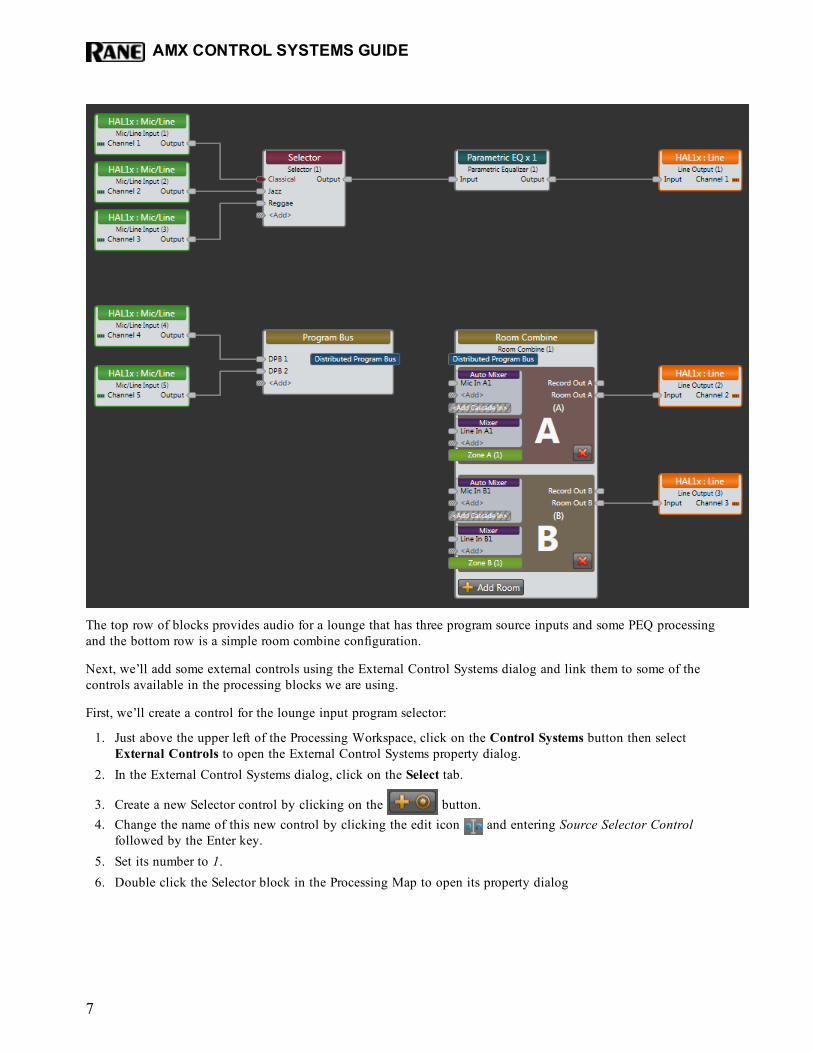
The top row of blocks provides audio for a lounge that has three program source inputs and some PEQ processingand the bottom row is a simple room combine configuration.
Next, we’ll add some external controls using the External Control Systems dialog and link them to some of thecontrols available in the processing blocks we are using.
First, we’ll create a control for the lounge input program selector:
1. Just above the upper left of the Processing Workspace, click on the Control Systems button then selectExternal Controls to open the External Control Systems property dialog.
2. In the External Control Systems dialog, click on the Select tab.
3. Create a new Selector control by clicking on the button.4. Change the name of this new control by clicking the edit icon and entering Source Selector Control
followed by the Enter key.5. Set its number to 1.6. Double click the Selector block in the Processing Map to open its property dialog
AMX CONTROL SYSTEMS GUIDE
7
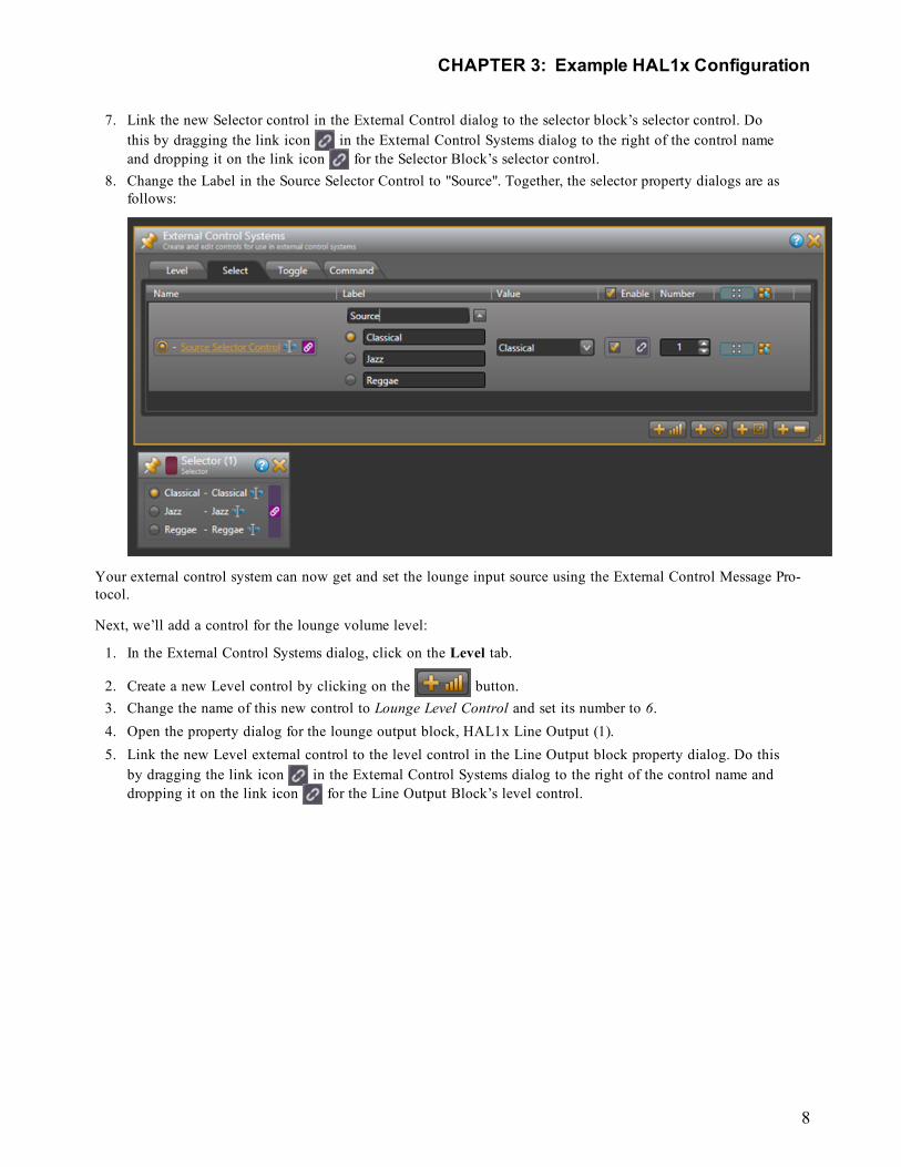
7. Link the new Selector control in the External Control dialog to the selector block’s selector control. Dothis by dragging the link icon in the External Control Systems dialog to the right of the control nameand dropping it on the link icon for the Selector Block’s selector control.
8. Change the Label in the Source Selector Control to "Source". Together, the selector property dialogs are asfollows:
Your external control system can now get and set the lounge input source using the External Control Message Pro-tocol.
Next, we’ll add a control for the lounge volume level:
1. In the External Control Systems dialog, click on the Level tab.
2. Create a new Level control by clicking on the button.3. Change the name of this new control to Lounge Level Control and set its number to 6.4. Open the property dialog for the lounge output block, HAL1x Line Output (1).5. Link the new Level external control to the level control in the Line Output block property dialog. Do this
by dragging the link icon in the External Control Systems dialog to the right of the control name anddropping it on the link icon for the Line Output Block’s level control.
CHAPTER 3: Example HAL1x Configuration
8
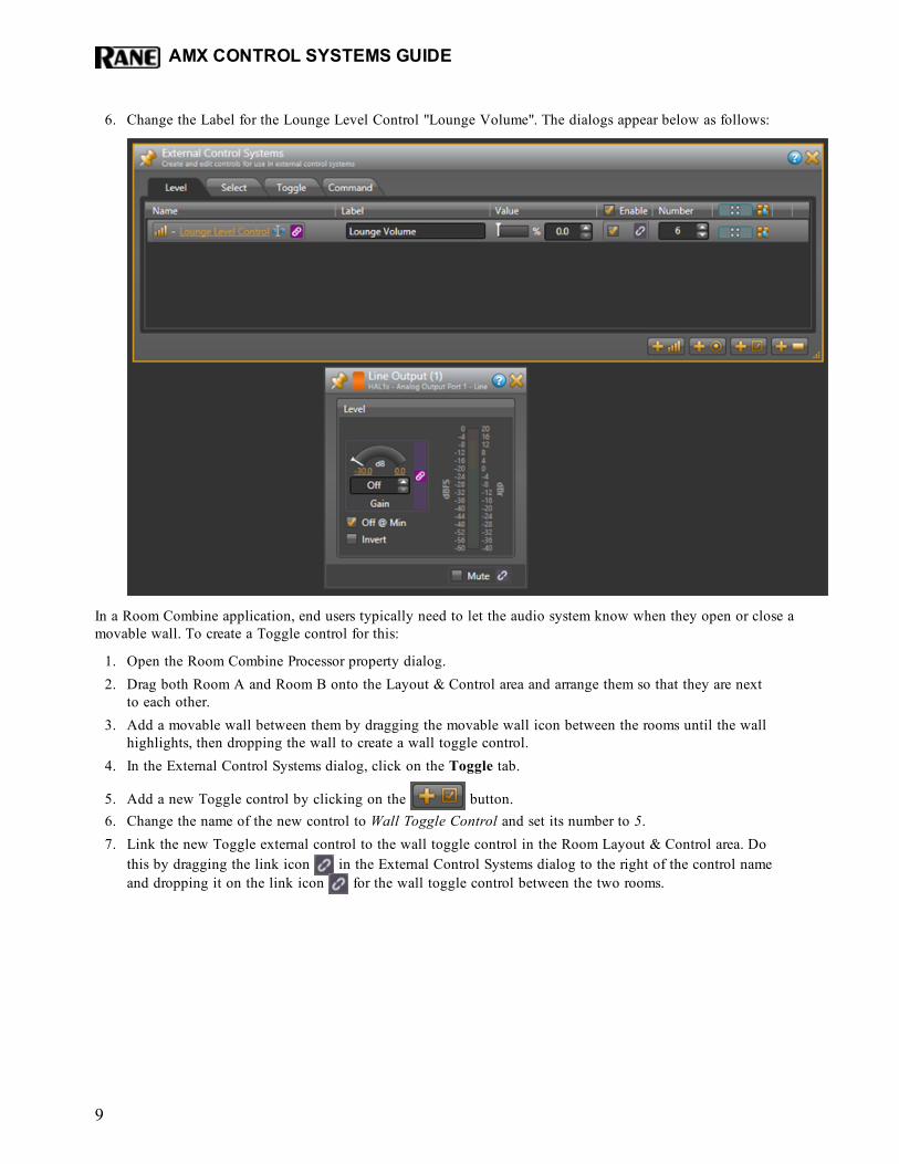
6. Change the Label for the Lounge Level Control "Lounge Volume". The dialogs appear below as follows:
In a Room Combine application, end users typically need to let the audio system know when they open or close amovable wall. To create a Toggle control for this:
1. Open the Room Combine Processor property dialog.2. Drag both Room A and Room B onto the Layout & Control area and arrange them so that they are next
to each other.3. Add a movable wall between them by dragging the movable wall icon between the rooms until the wall
highlights, then dropping the wall to create a wall toggle control.4. In the External Control Systems dialog, click on the Toggle tab.
5. Add a new Toggle control by clicking on the button.6. Change the name of the new control to Wall Toggle Control and set its number to 5.7. Link the new Toggle external control to the wall toggle control in the Room Layout & Control area. Do
this by dragging the link icon in the External Control Systems dialog to the right of the control nameand dropping it on the link icon for the wall toggle control between the two rooms.
AMX CONTROL SYSTEMS GUIDE
9
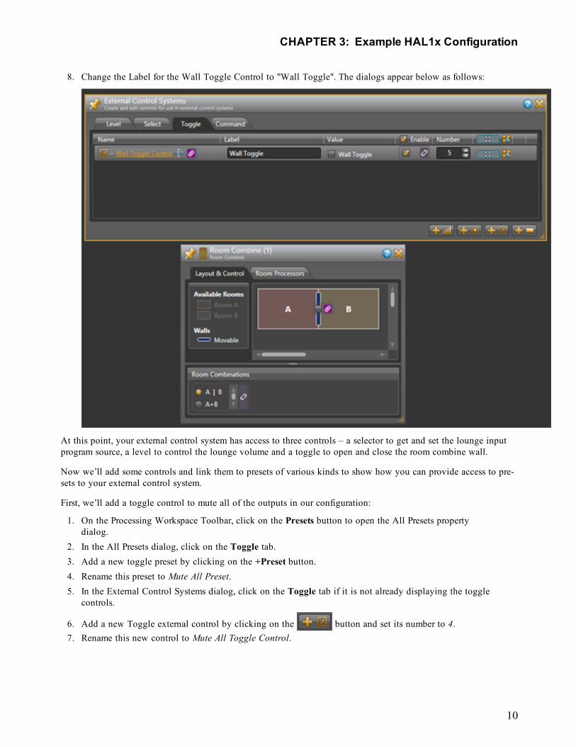
8. Change the Label for the Wall Toggle Control to "Wall Toggle". The dialogs appear below as follows:
At this point, your external control system has access to three controls – a selector to get and set the lounge inputprogram source, a level to control the lounge volume and a toggle to open and close the room combine wall.
Now we’ll add some controls and link them to presets of various kinds to show how you can provide access to pre-sets to your external control system.
First, we’ll add a toggle control to mute all of the outputs in our configuration:
1. On the Processing Workspace Toolbar, click on the Presets button to open the All Presets propertydialog.
2. In the All Presets dialog, click on the Toggle tab.3. Add a new toggle preset by clicking on the +Preset button.4. Rename this preset to Mute All Preset.5. In the External Control Systems dialog, click on the Toggle tab if it is not already displaying the toggle
controls.
6. Add a new Toggle external control by clicking on the button and set its number to 4.7. Rename this new control to Mute All Toggle Control.
CHAPTER 3: Example HAL1x Configuration
10
8. Link the new Mute All Toggle Control to the toggle control for the Mute All Preset. Do this by draggingthe link icon in the External Control Systems dialog to the right of the control name and dropping iton the link icon for the Mute All Preset’s toggle control.
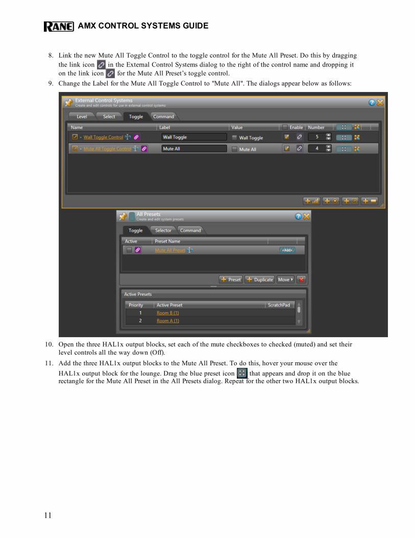
9. Change the Label for the Mute All Toggle Control to "Mute All". The dialogs appear below as follows:
10. Open the three HAL1x output blocks, set each of the mute checkboxes to checked (muted) and set theirlevel controls all the way down (Off).
11. Add the three HAL1x output blocks to the Mute All Preset. To do this, hover your mouse over theHAL1x output block for the lounge. Drag the blue preset icon that appears and drop it on the bluerectangle for the Mute All Preset in the All Presets dialog. Repeat for the other two HAL1x output blocks.
AMX CONTROL SYSTEMS GUIDE
11
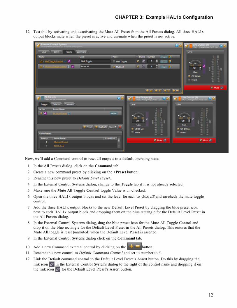
12. Test this by activating and deactivating the Mute All Preset from the All Presets dialog. All three HAL1xoutput blocks mute when the preset is active and un-mute when the preset is not active.
Now, we’ll add a Command control to reset all outputs to a default operating state:
1. In the All Presets dialog, click on the Command tab.2. Create a new command preset by clicking on the +Preset button.3. Rename this new preset to Default Level Preset.4. In the External Control Systems dialog, change to the Toggle tab if it is not already selected.5. Make sure the Mute All Toggle Control toggle Value is un-checked.6. Open the three HAL1x output blocks and set the level for each to -20.0 dB and un-check the mute toggle
control.7. Add the three HAL1x output blocks to the new Default Level Preset by dragging the blue preset icon
next to each HAL1x output block and dropping them on the blue rectangle for the Default Level Preset inthe All Presets dialog.
8. In the External Control Systems dialog, drag the blue preset icon for the Mute All Toggle Control anddrop it on the blue rectangle for the Default Level Preset in the All Presets dialog. This ensures that theMute All toggle is reset (unmuted) when the Default Level Preset is asserted.
9. In the External Control Systems dialog click on the Command tab.
10. Add a new Command external control by clicking on the button.11. Rename this new control to Default Command Control and set its number to 3.12. Link the Default command control to the Default Level Preset’s Assert button. Do this by dragging the
link icon in the External Control Systems dialog to the right of the control name and dropping it onthe link icon for the Default Level Preset’s Assert button.
CHAPTER 3: Example HAL1x Configuration
12
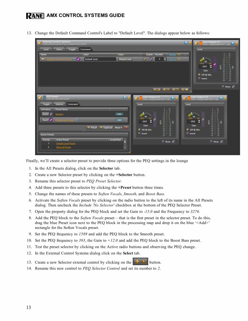
13. Change the Default Command Control's Label to "Default Level". The dialogs appear below as follows:
Finally, we’ll create a selector preset to provide three options for the PEQ settings in the lounge
1. In the All Presets dialog, click on the Selector tab.2. Create a new Selector preset by clicking on the +Selector button.3. Rename this selector preset to PEQ Preset Selector.4. Add three presets to this selector by clicking the +Preset button three times.5. Change the names of these presets to Soften Vocals, Smooth, and Boost Bass.6. Activate the Soften Vocals preset by clicking on the radio button to the left of its name in the All Presets
dialog. Then uncheck the Include 'No Selector' checkbox at the bottom of the PEQ Selector Preset.7. Open the property dialog for the PEQ block and set the Gain to -15.0 and the Frequency to 3276.8. Add the PEQ block to the Soften Vocals preset – that is the first preset in the selector preset. To do this,
drag the blue Preset icon next to the PEQ block in the processing map and drop it on the blue ‘<Add>’rectangle for the Soften Vocals preset.
9. Set the PEQ frequency to 1589 and add the PEQ block to the Smooth preset.10. Set the PEQ frequency to 393, the Gain to +12.0 and add the PEQ block to the Boost Bass preset.11. Test the preset selector by clicking on the Active radio buttons and observing the PEQ change.12. In the External Control Systems dialog click on the Select tab.
13. Create a new Selector external control by clicking on the button.14. Rename this new control to PEQ Selector Control and set its number to 2.
AMX CONTROL SYSTEMS GUIDE
13
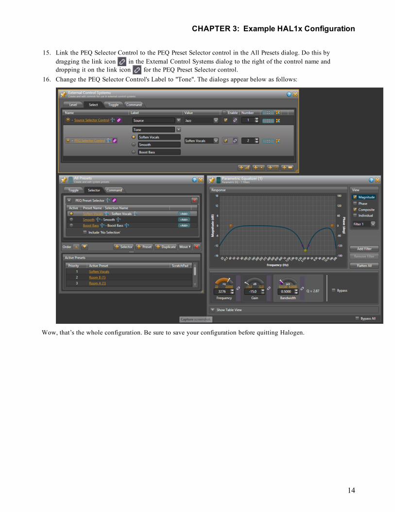
15. Link the PEQ Selector Control to the PEQ Preset Selector control in the All Presets dialog. Do this bydragging the link icon in the External Control Systems dialog to the right of the control name anddropping it on the link icon for the PEQ Preset Selector control.
16. Change the PEQ Selector Control's Label to "Tone". The dialogs appear below as follows:
Wow, that’s the whole configuration. Be sure to save your configuration before quitting Halogen.
CHAPTER 3: Example HAL1x Configuration
14
Configuration SummaryThe example configuration provides the following external controls:
1. A Selector for lounge program source – control number 1
There are three selections: Classical, Jazz, and Reggae
2. A Selector for lounge tone (PEQ) – control number 2
There are three selections: Soften Vocals, Smooth, and Boost Bass.
3. A Level for lounge volume – control number 6
This changes the output block’s level for the lounge.
4. A Toggle to mute all audio outputs – control number 4
This mutes all output blocks and sets their levels to Off. While setting the levels is not necessary, we’veincluded it here to cause the lounge output level to change so the Halogen/HAL Control Server will senda ‘set level’ message.
5. A Toggle to open and close the wall of a room combine block – control number 56. A Command to reset audio outputs to default levels – control number 3
This sets the three outputs to -20.0dB and un-mutes them. In addition, it sets the Mute All toggle controlto unchecked so the state is consistent with the outputs being un-muted.
AMX CONTROL SYSTEMS GUIDE
15
CHAPTER4: IntegratingAMXControl SystemswithHAL
OverviewThis guide describes how to set up an AMX controller and touch panel to communicate with a Halogen/HAL Con-trol Server. It is designed to be used in conjunction with the files found in the AMX Support Package. The con-tents of this support package include:
l AMXControlSystems_Guide.pdf - The guide you are reading nowl ControlSystemSample.hal - Halogen configuration file intended for loading in Halogen or your HAL1xl Rane_HAL.apw - NetLinx Studio program project filel Main.axs - NetLinx program source filel Rane_HAL_TP.TP4 - TPDesign4 touch panel project file
The AMX Support Package is installed with the Halogen software and can be accessed from the Windows StartMenu under Rane Corporation -> Halogen -> Guides -> AMX. If you want to access the files directly they areavailable on the product DVD or from the Halogen install directory:
l Windows 7 or Vista - C:\Program Files (x86)\Rane Corporation\Halogen\Guides\Support Packages\AMXdirectory
l Windows XP - C:\Program Files\Rane Corporation\Halogen\Guides\Support Packages\AMX directory.
You can also download the most up-to-date version of this support package from the Rane website(http://rane.com/hal).
NOTE: You do not need to connect your controller to an actual HAL in order to test your control system. APC running Halogen can simulate all the feedback your controller would get from a HAL running the sameconfiguration.
The HAL system has four types of controls: toggles, commands, levels and selectors. All four are accessible toexternal TCP/IP clients like an AMX controller. This guide walks you through the code for a TCP/IP client beforelooking closely at each of the HAL control types one-by-one. We dive into code for these HAL control types byimplementing a series of touch panel applications. These applications are:
l Toggle button to activate and deactivate a presetl Toggle button to open and close a wall in a room combine blockl Command button to assert a presetl Slider to adjust the level on an outputl Radio buttons to select between input sourcesl Radio buttons to select between presets
The guide concludes with a troubleshooting section that covers the most common problems encountered when con-figuring a target system for the examples.
16
ChecklistTo use the files from the AMX Support Package and follow along with the examples you will need:
l A Windows desktop or laptop with an Ethernet port and the latest Rane Halogen (1.1.0 or higher) andAMX NetLinx Studio and TPDesign software installed.
l An AMX NetLinx controller. The NI-700 is sufficient.l An AMX Modero NXT-CV7 touch panel. Alternatively, you could create a new TPDesign project targeting
a different touch panel model and copy the example over.l An Ethernet switch and cables for the PC, controller and touch panel.
Although you ultimately connect a HAL to your control system, all of the integration and testing can be accom-plished without a HAL.
This guide assumes that the reader has had some exposure to AMX programming and is able to navigate the AMXsoftware. A typical workflow for developing an AMX application is:
l Define constants for devices, buttons and levels in NetLinx Studio.l Code event handlers and feedback statements in NetLinx Studio.l Compile the program and transfer it to your controller.l Draw a custom touch panel user interface in TPDesign.l Assign device channel numbers from the program to buttons and sliders in the user interface.l Compile the user interface and transfer it to your touch panel[s].
Once your application is running, you can use NetLinx Studio’s debugger to set breakpoints, watch variables andstep through your program.
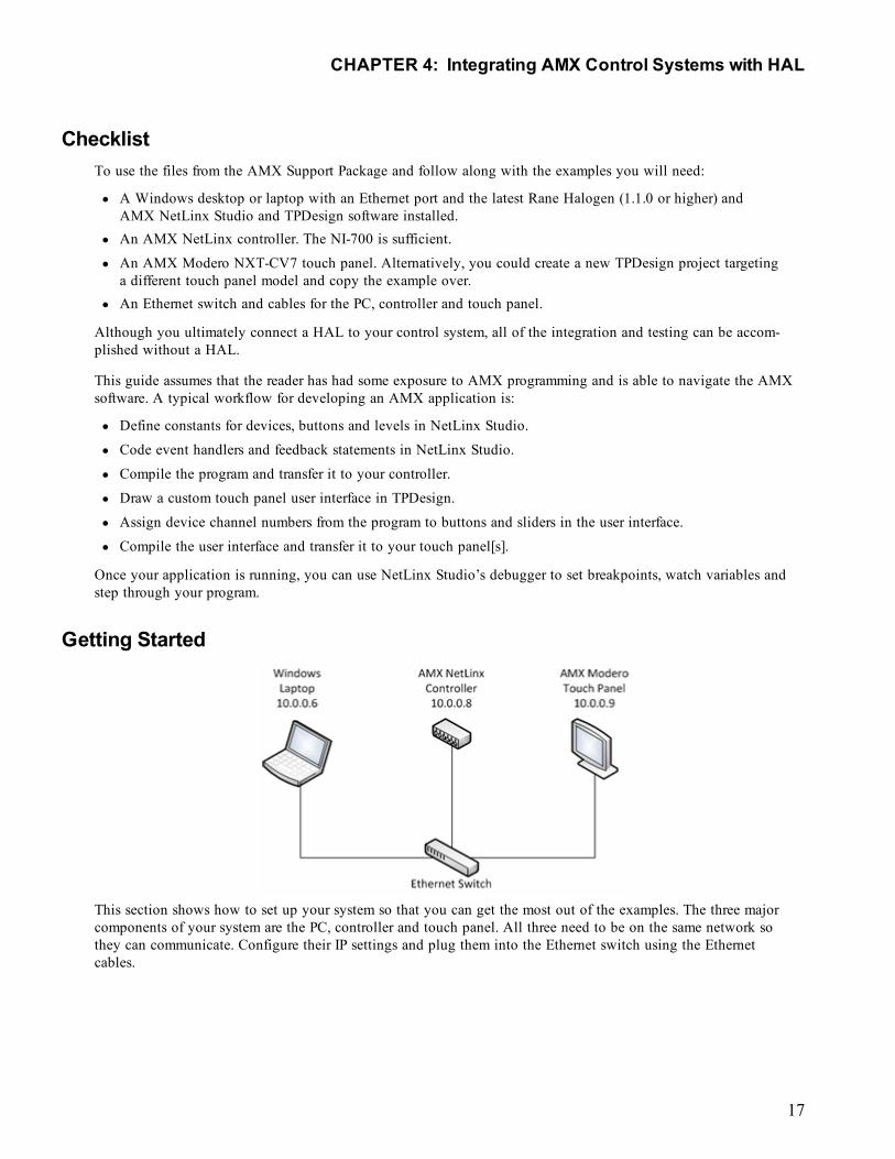
Getting Started
This section shows how to set up your system so that you can get the most out of the examples. The three majorcomponents of your system are the PC, controller and touch panel. All three need to be on the same network sothey can communicate. Configure their IP settings and plug them into the Ethernet switch using the Ethernetcables.
CHAPTER 4: Integrating AMX Control Systems with HAL
17
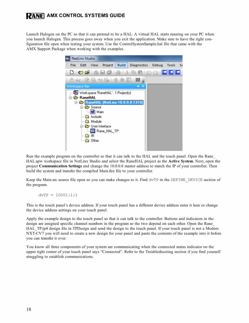
Launch Halogen on the PC so that it can pretend to be a HAL. A virtual HAL starts running on your PC whenyou launch Halogen. This process goes away when you exit the application. Make sure to have the right con-figuration file open when testing your system. Use the ControlSystemSample.hal file that came with theAMX Support Package when working with the examples.
Run the example program on the controller so that it can talk to the HAL and the touch panel. Open the Rane_HAL.apw workspace file in NetLinx Studio and select the RaneHAL project as the Active System. Next, open theproject Communication Settings and change the 10.0.0.8 master address to match the IP of your controller. Thenbuild the system and transfer the compiled Main.tkn file to your controller.
Keep the Main.src source file open so you can make changes to it. Find dvTP in the DEFINE_DEVICE section ofthe program.
dvTP = 10001:1:1
This is the touch panel’s device address. If your touch panel has a different device address enter it here or changethe device address settings on your touch panel.
Apply the example design to the touch panel so that it can talk to the controller. Buttons and indicators in thedesign are assigned specific channel numbers in the program so the two depend on each other. Open the Rane_HAL_TP.tp4 design file in TPDesign and send the design to the touch panel. If your touch panel is not a ModeroNXT-CV7 you will need to create a new design for your panel and paste the contents of the example into it beforeyou can transfer it over.
You know all three components of your system are communicating when the connected status indicator on theupper right corner of your touch panel says “Connected”. Refer to the Troubleshooting section if you find yourselfstruggling to establish communications.
AMX CONTROL SYSTEMS GUIDE
18
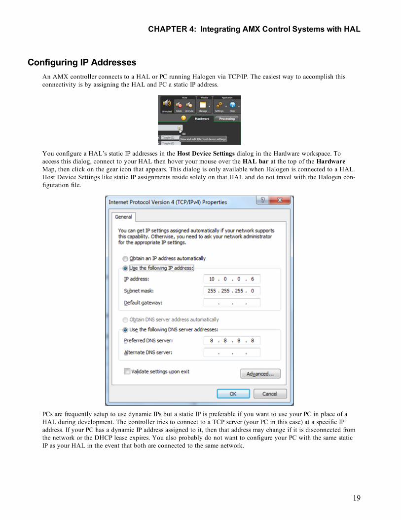
Configuring IP AddressesAn AMX controller connects to a HAL or PC running Halogen via TCP/IP. The easiest way to accomplish thisconnectivity is by assigning the HAL and PC a static IP address.
You configure a HAL’s static IP addresses in the Host Device Settings dialog in the Hardware workspace. Toaccess this dialog, connect to your HAL then hover your mouse over the HAL bar at the top of the HardwareMap, then click on the gear icon that appears. This dialog is only available when Halogen is connected to a HAL.Host Device Settings like static IP assignments reside solely on that HAL and do not travel with the Halogen con-figuration file.
PCs are frequently setup to use dynamic IPs but a static IP is preferable if you want to use your PC in place of aHAL during development. The controller tries to connect to a TCP server (your PC in this case) at a specific IPaddress. If your PC has a dynamic IP address assigned to it, then that address may change if it is disconnected fromthe network or the DHCP lease expires. You also probably do not want to configure your PC with the same staticIP as your HAL in the event that both are connected to the same network.
CHAPTER 4: Integrating AMX Control Systems with HAL
19
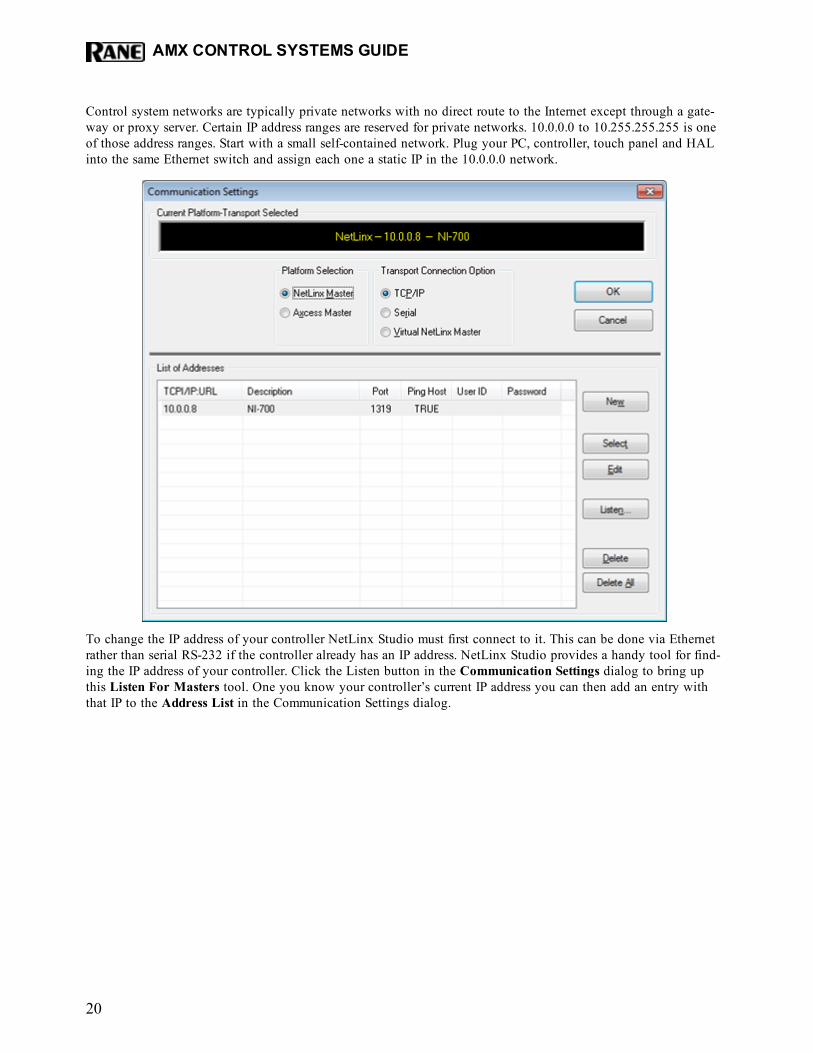
Control system networks are typically private networks with no direct route to the Internet except through a gate-way or proxy server. Certain IP address ranges are reserved for private networks. 10.0.0.0 to 10.255.255.255 is oneof those address ranges. Start with a small self-contained network. Plug your PC, controller, touch panel and HALinto the same Ethernet switch and assign each one a static IP in the 10.0.0.0 network.
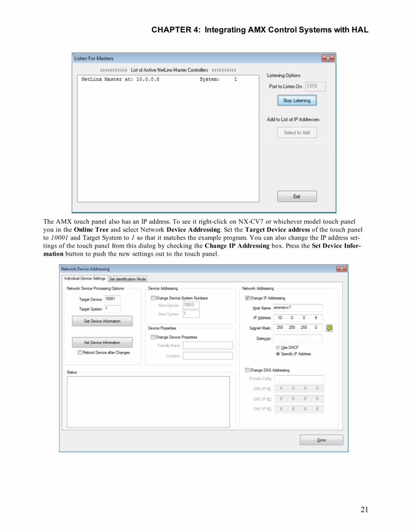
To change the IP address of your controller NetLinx Studio must first connect to it. This can be done via Ethernetrather than serial RS-232 if the controller already has an IP address. NetLinx Studio provides a handy tool for find-ing the IP address of your controller. Click the Listen button in the Communication Settings dialog to bring upthis Listen For Masters tool. One you know your controller’s current IP address you can then add an entry withthat IP to the Address List in the Communication Settings dialog.
AMX CONTROL SYSTEMS GUIDE
20
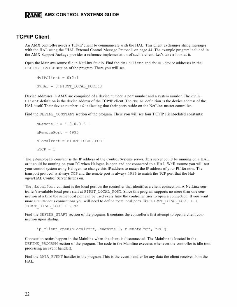
The AMX touch panel also has an IP address. To see it right-click on NX-CV7 or whichever model touch panelyou in the Online Tree and select Network Device Addressing. Set the Target Device address of the touch panelto 10001 and Target System to 1 so that it matches the example program. You can also change the IP address set-tings of the touch panel from this dialog by checking the Change IP Addressing box. Press the Set Device Infor-mation button to push the new settings out to the touch panel.
CHAPTER 4: Integrating AMX Control Systems with HAL
21
TCP/IP ClientAn AMX controller needs a TCP/IP client to communicate with the HAL. This client exchanges string messageswith the HAL using the "HAL External Control Message Protocol" on page 44. The example program included inthe AMX Support Package provides a reference implementation of such a client. Let’s take a look at it.
Open the Main.axs source file in NetLinx Studio. Find the dvIPClient and dvHAL device addresses in theDEFINE_DEVICE section of the program. There you will see:
dvIPClient = 0:2:1
dvHAL = 0:FIRST_LOCAL_PORT:0
Device addresses in AMX are comprised of a device number, a port number and a system number. The dvIP-Client definition is the device address of the TCP/IP client. The dvHAL definition is the device address of theHAL itself. Their device number is 0 indicating that their ports reside on the NetLinx master controller.
Find the DEFINE_CONSTANT section of the program. There you will see four TCP/IP client-related constants:
sRemoteIP = '10.0.0.6 '
nRemotePort = 4996
nLocalPort = FIRST_LOCAL_PORT
nTCP = 1
The sRemoteIP constant is the IP address of the Control Systems server. This server could be running on a HALor it could be running on your PC when Halogen is open and not connected to a HAL. We'll assume you will testyour control system using Halogen, so change this IP address to match the IP address of your PC for now. Thetransport protocol is always TCP and the remote port is always 4996 to match the TCP port that the Hal-ogen/HAL Control Server listens on.
The nLocalPort constant is the local port on the controller that identifies a client connection. A NetLinx con-troller’s available local ports start at FIRST_LOCAL_PORT. Since this program supports no more than one con-nection at a time the same local port can be used every time the controller tries to open a connection. If you wantmore simultaneous connections you will need to define more local ports like: FIRST_LOCAL_PORT + 1,FIRST_LOCAL_PORT + 2, etc.
Find the DEFINE_START section of the program. It contains the controller’s first attempt to open a client con-nection upon startup.
ip_client_open(nLocalPort, sRemoteIP, nRemotePort, nTCP)
Connection retries happen in the Mainline when the client is disconnected. The Mainline is located in theDEFINE_PROGRAM section of the program. The code in the Mainline executes whenever the controller is idle (notprocessing an event handler).
Find the DATA_EVENT handler in the program. This is the event handler for any data the client receives from theHAL.
AMX CONTROL SYSTEMS GUIDE
22

DATA_EVENT[dvHAL]{ONLINE:{…bConnected = 1…
}OFFLINE:{bConnected = 0ip_client_close(nLocalPort)
}STRING:{…
}…
}
The ONLINE event is triggered when an ip_client_open call succeeds in connecting to the HAL. The OFF-LINE event is raised when the connection to the HAL is dropped. A variable named bConnected keeps track ofthe client’s connected state. This variable sends feedback to a connection status indicator on the touch panel.
The ONLINE event is handled by requesting the live values of various controls from the HAL. This initial queryensures that the values displayed on the touch panel reflect the current state of the HAL.
Any actual data that the client receives from the HAL gets processed in the STRING event handler. This handlercontains code to parse HAL control values that are sent back in response to a query from the IP client, or thatarrive unsolicited because some other client changed or requested them. Refer to the button and level event han-dlers later on in this guide for code to build and send HAL control values.
TogglesThis section explains how to integrate HAL toggle controls with buttons on an AMX touch panel by examining acouple of applications: a toggle preset button and a wall toggle button on a touch panel. We start by dissectingthe code for the HAL toggle controls and touch panel toggle buttons. Then we demonstrate how to bind HAL tog-gle controls to buttons in the touch panel user interface.
Toggles in a HAL system have only an on or off state. They are represented as checkboxes in the Halogen soft-ware and DR remotes. Because toggles only have two states they are modeled as integers with values of 0 and 1 inNetLinx. The example program provides code for handling toggle button events from the touch panel and parsingtoggle message strings from a HAL. Let’s take a look at it.
Open the Main.axs source file in NetLinx Studio. Find the DEFINE_CONSTANT section of the program. It con-tains some toggle-related constants:
BTN_MUTE_ALL = 4
BTN_WALL_OPEN = 5
CHAPTER 4: Integrating AMX Control Systems with HAL
23
…
INTEGER nToggleChannels[] = { BTN_MUTE_ALL, BTN_WALL_OPEN }
This code says that there are two HAL toggle controls in this program and that their touch panel device channelnumbers are 4 and 5. The 4 and the 5 are also HAL control numbers used to uniquely identify controls on theHAL. These control numbers appear in the External Control Systems dialog of the Halogen software. Matchingdevice channel numbers with HAL control numbers makes programming multiple HAL toggle controls easy.
The example toggle code is reusable across applications. If you want more toggle buttons on the touch panel justadd more device channel numbers to the nToggleChannels array. Coding a new toggle application is simply amatter of matching HAL toggle control numbers in Halogen with newly-added toggle button device channelnumbers in AMX.
There is one button event handler for all of the toggle buttons on the touch panel. Feel free to copy and pasteevent handler into your own programs.
BUTTON_EVENT[dvTP, nToggleChannels]{RELEASE:{nToggleIndex = GET_LAST(nToggleChannels)
if (nToggleIndex > 0 &&nToggleIndex <= length_array(nToggleChannels))
{bToggleValues[nToggleIndex] =!bToggleValues[nToggleIndex]
Send_String dvHAL, "'<T&',itoa(nToggleChannels[nToggleIndex]), '&',itoa(bToggleValues[nToggleIndex]), '>'"
}}
}
A button event handler does not have to take a single device channel as its channel reference parameter. It canaccept an array of device channel numbers. In the case of our touch panel’s toggle button event handler, all of thetoggle buttons’ device channel numbers are passed in through the nToggleChannels argument. The handlerknows which toggle button on the touch panel fired the event because the GET_LAST call returns the index ofthat button in the nToggleChannels array.
Whenever a toggle button on a touch panel is released the toggle button event handler sends a message string witha new toggle value to the HAL. These ‘set toggle’ messages contain a toggle control type, HAL control numberand value. Valid ‘set toggle’ messages for the two HAL toggle controls in this example would be <T&4&0>,<T&4&1>, <T&5&0> and <T&5&1>.
NOTE: Refer to Appendix A "HAL External Control Message Protocol" on page 44 for more information ontoggle messages.
AMX CONTROL SYSTEMS GUIDE
24
The HAL sends these same ‘set toggle’ messages to the controller when another client changes a HAL toggle con-trol value. Here is the STRING event handler code to parse incoming HAL toggle control values.
active(find_string(cData, '<T&', 1)):{remove_string(cData, '<T&', 1)
nToggleIndex = FindToggleIndex(atoi(cData))
remove_string(cData, '&', 1)
if (nToggleIndex > 0 &&nToggleIndex <= length_array(nToggleChannels))
{bToggleValues[nToggleIndex] = atoi(cData)
}remove_string(cData, '>', 1)
}
The Mainline contains feedback statements for all the defined toggles. These feedback statements update the vis-ible state of toggle buttons on the touch panel in response to HAL toggle control value changes triggered bytouch panel button presses or messages from the HAL.
for (nToggleIndex = 1;nToggleIndex <= length_array(nToggleChannels);nToggleIndex++)
{[dvTP, nToggleChannels[nToggleIndex]] =
bToggleValues[nToggleIndex]}
The controller requests HAL toggle control values from the HAL upon connecting. This ensures that the togglebuttons on the touch panel are in sync with the live toggle values on the HAL. The controller does this by send-ing ‘get toggle’ messages to the HAL when the ONLINE event is fired. These ‘get toggle’ messages consist of atoggle control type and HAL control number. See the toggles for loop in the client’s ONLINE event handler forhow to encode and send them.
for (i = 1;i <= length_array(nToggleChannels);i++)
{Send_String dvHAL, "'<T&', itoa(nToggleChannels[i]), '>'"
}
The ‘get toggle’ messages for this example are <T&4> and <T&5>. Upon receipt of these ‘get toggle’ messages theHAL responds with ‘set toggle’ messages for those two HAL toggle controls.
CHAPTER 4: Integrating AMX Control Systems with HAL
25
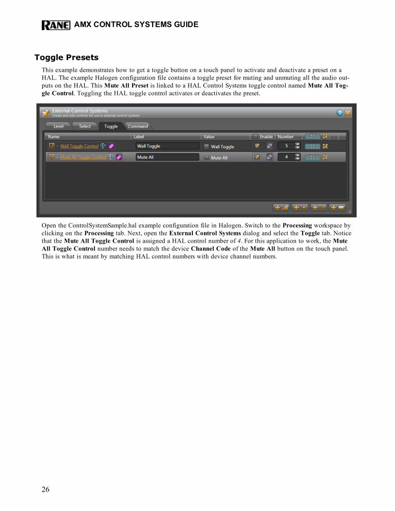
Toggle PresetsThis example demonstrates how to get a toggle button on a touch panel to activate and deactivate a preset on aHAL. The example Halogen configuration file contains a toggle preset for muting and unmuting all the audio out-puts on the HAL. This Mute All Preset is linked to a HAL Control Systems toggle control named Mute All Tog-gle Control. Toggling the HAL toggle control activates or deactivates the preset.
Open the ControlSystemSample.hal example configuration file in Halogen. Switch to the Processing workspace byclicking on the Processing tab. Next, open the External Control Systems dialog and select the Toggle tab. Noticethat the Mute All Toggle Control is assigned a HAL control number of 4. For this application to work, the MuteAll Toggle Control number needs to match the device Channel Code of the Mute All button on the touch panel.This is what is meant by matching HAL control numbers with device channel numbers.
AMX CONTROL SYSTEMS GUIDE
26
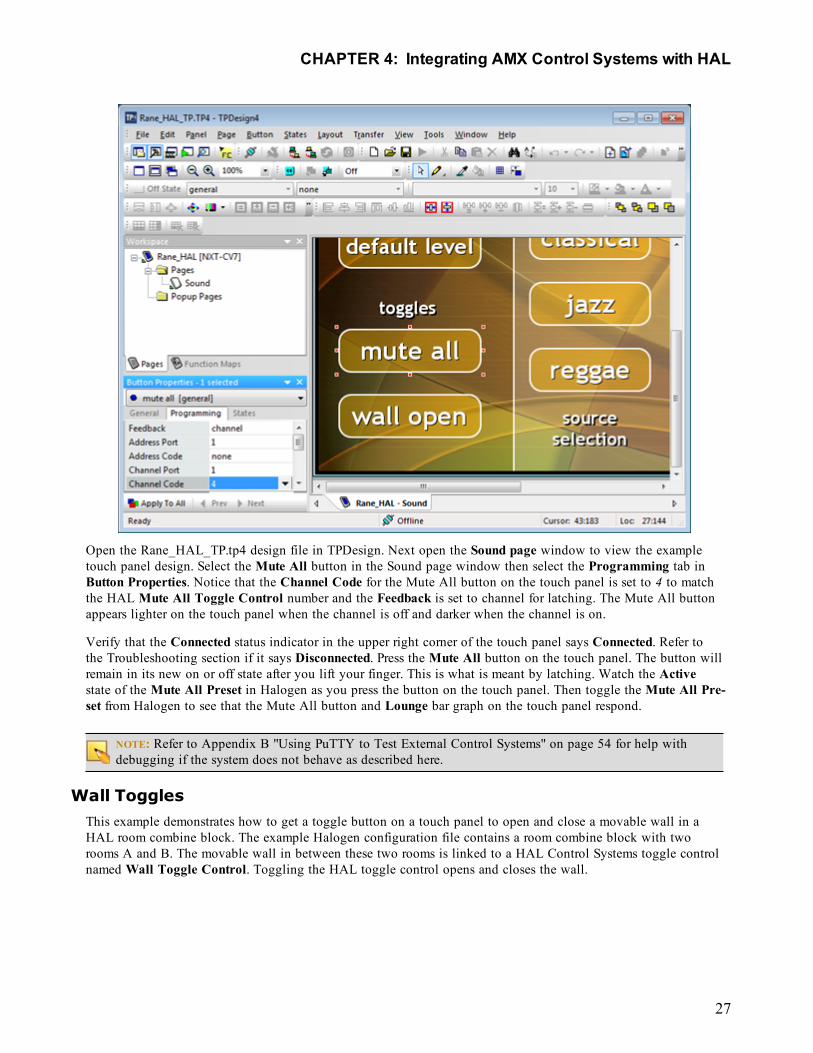
Open the Rane_HAL_TP.tp4 design file in TPDesign. Next open the Sound page window to view the exampletouch panel design. Select the Mute All button in the Sound page window then select the Programming tab inButton Properties. Notice that the Channel Code for the Mute All button on the touch panel is set to 4 to matchthe HAL Mute All Toggle Control number and the Feedback is set to channel for latching. The Mute All buttonappears lighter on the touch panel when the channel is off and darker when the channel is on.
Verify that the Connected status indicator in the upper right corner of the touch panel says Connected. Refer tothe Troubleshooting section if it says Disconnected. Press the Mute All button on the touch panel. The button willremain in its new on or off state after you lift your finger. This is what is meant by latching. Watch the Activestate of the Mute All Preset in Halogen as you press the button on the touch panel. Then toggle the Mute All Pre-set from Halogen to see that the Mute All button and Lounge bar graph on the touch panel respond.
NOTE: Refer to Appendix B "Using PuTTY to Test External Control Systems" on page 54 for help withdebugging if the system does not behave as described here.
Wall TogglesThis example demonstrates how to get a toggle button on a touch panel to open and close a movable wall in aHAL room combine block. The example Halogen configuration file contains a room combine block with tworooms A and B. The movable wall in between these two rooms is linked to a HAL Control Systems toggle controlnamed Wall Toggle Control. Toggling the HAL toggle control opens and closes the wall.
CHAPTER 4: Integrating AMX Control Systems with HAL
27
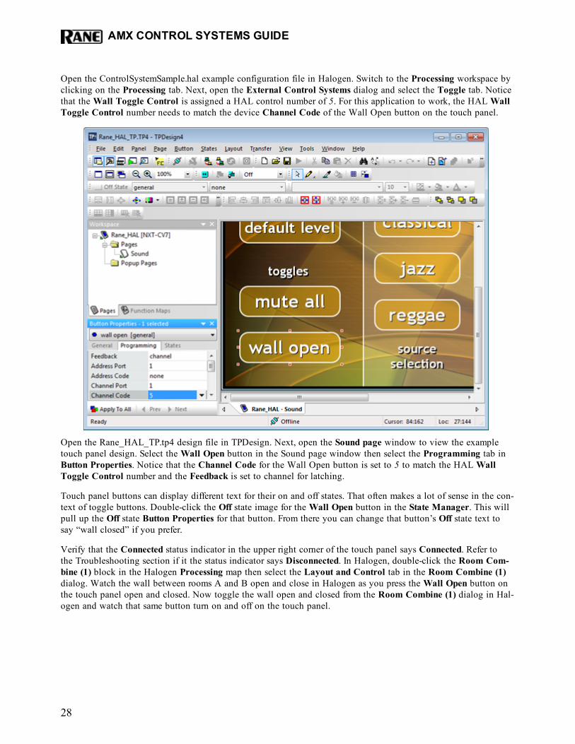
Open the ControlSystemSample.hal example configuration file in Halogen. Switch to the Processing workspace byclicking on the Processing tab. Next, open the External Control Systems dialog and select the Toggle tab. Noticethat the Wall Toggle Control is assigned a HAL control number of 5. For this application to work, the HAL WallToggle Control number needs to match the device Channel Code of the Wall Open button on the touch panel.
Open the Rane_HAL_TP.tp4 design file in TPDesign. Next, open the Sound page window to view the exampletouch panel design. Select the Wall Open button in the Sound page window then select the Programming tab inButton Properties. Notice that the Channel Code for the Wall Open button is set to 5 to match the HAL WallToggle Control number and the Feedback is set to channel for latching.
Touch panel buttons can display different text for their on and off states. That often makes a lot of sense in the con-text of toggle buttons. Double-click the Off state image for the Wall Open button in the State Manager. This willpull up the Off state Button Properties for that button. From there you can change that button’s Off state text tosay “wall closed” if you prefer.
Verify that the Connected status indicator in the upper right corner of the touch panel says Connected. Refer tothe Troubleshooting section if it the status indicator says Disconnected. In Halogen, double-click the Room Com-bine (1) block in the Halogen Processing map then select the Layout and Control tab in the Room Combine (1)dialog. Watch the wall between rooms A and B open and close in Halogen as you press the Wall Open button onthe touch panel open and closed. Now toggle the wall open and closed from the Room Combine (1) dialog in Hal-ogen and watch that same button turn on and off on the touch panel.
AMX CONTROL SYSTEMS GUIDE
28
NOTE: Refer to Appendix B "Using PuTTY to Test External Control Systems" on page 54 for help withdebugging if the system does not behave as described here.
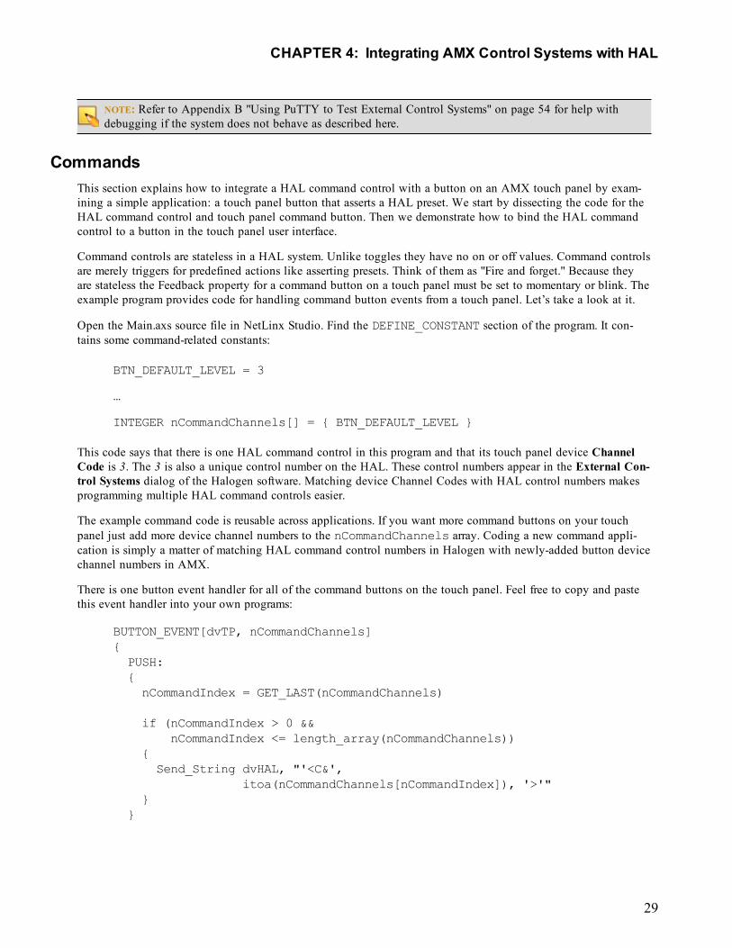
CommandsThis section explains how to integrate a HAL command control with a button on an AMX touch panel by exam-ining a simple application: a touch panel button that asserts a HAL preset. We start by dissecting the code for theHAL command control and touch panel command button. Then we demonstrate how to bind the HAL commandcontrol to a button in the touch panel user interface.
Command controls are stateless in a HAL system. Unlike toggles they have no on or off values. Command controlsare merely triggers for predefined actions like asserting presets. Think of them as "Fire and forget." Because theyare stateless the Feedback property for a command button on a touch panel must be set to momentary or blink. Theexample program provides code for handling command button events from a touch panel. Let’s take a look at it.
Open the Main.axs source file in NetLinx Studio. Find the DEFINE_CONSTANT section of the program. It con-tains some command-related constants:
BTN_DEFAULT_LEVEL = 3
…
INTEGER nCommandChannels[] = { BTN_DEFAULT_LEVEL }
This code says that there is one HAL command control in this program and that its touch panel device ChannelCode is 3. The 3 is also a unique control number on the HAL. These control numbers appear in the External Con-trol Systems dialog of the Halogen software. Matching device Channel Codes with HAL control numbers makesprogramming multiple HAL command controls easier.
The example command code is reusable across applications. If you want more command buttons on your touchpanel just add more device channel numbers to the nCommandChannels array. Coding a new command appli-cation is simply a matter of matching HAL command control numbers in Halogen with newly-added button devicechannel numbers in AMX.
There is one button event handler for all of the command buttons on the touch panel. Feel free to copy and pastethis event handler into your own programs:
BUTTON_EVENT[dvTP, nCommandChannels]{PUSH:{nCommandIndex = GET_LAST(nCommandChannels)
if (nCommandIndex > 0 &&nCommandIndex <= length_array(nCommandChannels))
{Send_String dvHAL, "'<C&',
itoa(nCommandChannels[nCommandIndex]), '>'"}
}
CHAPTER 4: Integrating AMX Control Systems with HAL
29
}
Whenever a command button is pressed on the touch panel this handler sends a message string to the HAL. These‘command’ messages contain a command control type and a HAL control number. The only valid ‘command’ mes-sage for the command in this example would be <C&3>.
NOTE: Refer to Appendix A "HAL External Control Message Protocol" on page 44 for more information oncommand messages.
When a client sends a ‘command’ message the HAL echoes it back to all its other clients. The controller currentlyignores unsolicited command messages but you can add code to parse them if you want your touch panel toexhibit feedback when they arrive. See the STRING section of the TCP/IP client’s DATA_EVENT handler for pars-ing techniques.
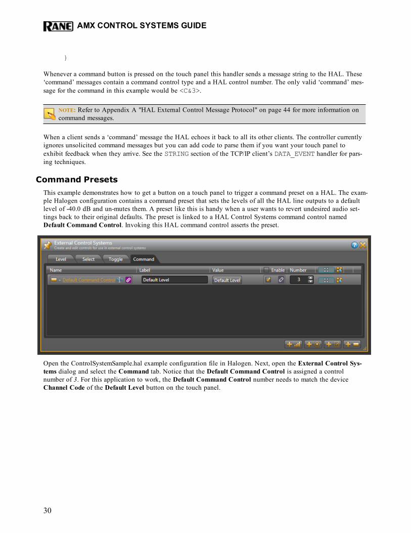
Command PresetsThis example demonstrates how to get a button on a touch panel to trigger a command preset on a HAL. The exam-ple Halogen configuration contains a command preset that sets the levels of all the HAL line outputs to a defaultlevel of -40.0 dB and un-mutes them. A preset like this is handy when a user wants to revert undesired audio set-tings back to their original defaults. The preset is linked to a HAL Control Systems command control namedDefault Command Control. Invoking this HAL command control asserts the preset.
Open the ControlSystemSample.hal example configuration file in Halogen. Next, open the External Control Sys-tems dialog and select the Command tab. Notice that the Default Command Control is assigned a controlnumber of 3. For this application to work, the Default Command Control number needs to match the deviceChannel Code of the Default Level button on the touch panel.
AMX CONTROL SYSTEMS GUIDE
30
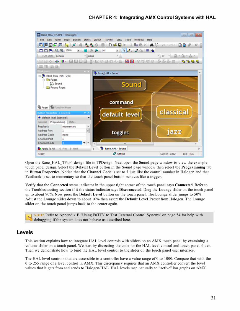
Open the Rane_HAL_TP.tp4 design file in TPDesign. Next open the Sound page window to view the exampletouch panel design. Select the Default Level button in the Sound page window then select the Programming tabin Button Properties. Notice that the Channel Code is set to 3 just like the control number in Halogen and thatFeedback is set to momentary so that the touch panel button behaves like a trigger.
Verify that the Connected status indicator in the upper right corner of the touch panel says Connected. Refer tothe Troubleshooting section if it the status indicator says Disconnected. Drag the Lounge slider on the touch panelup to about 90%. Now press the Default Level button on the touch panel. The Lounge slider jumps to 50%.Adjust the Lounge slider down to about 10% then assert the Default Level Preset from Halogen. The Loungeslider on the touch panel jumps back to the center again.
NOTE: Refer to Appendix B "Using PuTTY to Test External Control Systems" on page 54 for help withdebugging if the system does not behave as described here.
LevelsThis section explains how to integrate HAL level controls with sliders on an AMX touch panel by examining avolume slider on a touch panel. We start by dissecting the code for the HAL level control and touch panel slider.Then we demonstrate how to bind the HAL level control to the slider on the touch panel user interface.
The HAL level controls that are accessible to a controller have a value range of 0 to 1000. Compare that with the0 to 255 range of a level control in AMX. This discrepancy requires that an AMX controller convert the levelvalues that it gets from and sends to Halogen/HAL. HAL levels map naturally to “active” bar graphs on AMX
CHAPTER 4: Integrating AMX Control Systems with HAL
31
touch panels. These touch-sensitive bar graphs act as sliders so this guide refers to them as such. The example pro-gram provides code for handling level events and parsing level strings from Halogen/HAL. Let’s take a look at it.
Open the Main.axs source file in NetLinx Studio. Find the DEFINE_CONSTANT section of the program. It con-tains some level-related constants:
LVL_LOUNGE_VOLUME = 6
…
INTEGER nLevelChannels[] = { LVL_LOUNGE_VOLUME }
This code says that there is one HAL level control in this program and that its touch panel device Level Code is6. The 6 is also a unique control number on the HAL. These control numbers appear in the External Control Sys-tems dialog of the Halogen software. Matching device channel numbers with control numbers makes programmingmultiple HAL level controls easier.
The example level code is reusable across applications. If you want more sliders on your touch panel just add moredevice channel numbers to the nLevelChannels array. Coding a new level application is simply a matter ofmatching HAL level control numbers in Halogen with newly-added slider device Level Codes in AMX.
There is one level event handler for all of the sliders on the touch panel. Feel free to copy and paste this event han-dler into your own programs:
LEVEL_EVENT[dvTP, nLevelChannels]{nLevelIndex = GET_LAST(nLevelChannels)
if (nLevelIndex > 0 &&nLevelIndex <= length_array(nLevelChannels))
{if (LEVEL.VALUE <> nLevelValues[nLevelIndex]){nLevelValues[nLevelIndex] = LEVEL.VALUE
Send_String dvHAL, "'<L&',itoa(nLevelChannels[nLevelIndex]), '&',itoa(nLevelValues[nLevelIndex] * 1000/255),'>'"
}}
}
When a slider on a touch panel is dragged the level event handler sends a message string with a new level valueto the HAL. These ‘set level’ messages contain a level control type, HAL control number and level value. Noticethe 1000/255 multiplier for the conversion from AMX to HAL level values. Valid ‘set level’ messages for theHAL level control in this example program would be <L&6&0>, <L&6&1>, <L&6&2> all the way to<L&6&1000>.
The HAL sends these same set level strings to the controller whenever another client changes a HAL level controlvalue. Here is the STRING event handler code to parse the incoming level values:
AMX CONTROL SYSTEMS GUIDE
32
active(find_string(cData, '<L&', 1)):{remove_string(cData, '<L&', 1)
nLevelIndex = FindLevelIndex(atoi(cData))
remove_string(cData, '&', 1)
if (nLevelIndex > 0 &&nLevelIndex <= length_array(nLevelChannels))
{nLevelValues[nLevelIndex] = atoi(cData) * 255/1000
send_level dvTP, nLevelChannels[nLevelIndex],nLevelValues[nLevelIndex]
}
remove_string(cData, '>', 1)}
Notice the 255/1000 multiplier for the conversion from HAL to AMX level values. A send_level call updatesthe slider on the touch panel to the new level that came from the HAL. Unlike toggles and selectors, there are nofeedback statements for levels in the Mainline.
The controller requests HAL level control values from the HAL upon connecting. This ensures that the sliders onthe touch panel are in sync with the live level value on the HAL. It does this by sending ‘get level’ messages tothe HAL when the ONLINE event is fired. These ‘get level’ messages consist of a level control type and HAL con-trol number. See the levels for loop in the client’s ONLINE event handler for how to encode and send them:
for (i = 1;i <= length_array(nLevelChannels);i++)
{Send_String dvHAL, "'<L&',
itoa(nLevelChannels[i]), '>'"}
The ‘get level’ message for the level in this example is <L&6>. Upon receipt of this ‘get level’ message the HALresponds with a ‘set level’ message for that HAL level control.
NOTE: Refer to Appendix A "HAL External Control Message Protocol" on page 44 for more information onlevel messages.
SlidersThis example demonstrates how to get a slider on a touch panel to manipulate the level on a HAL output. Theexample Halogen configuration contains a HAL line output wired to a lounge. The remaining HAL line outputsgo to rooms A and B. The level on the lounge output is linked to a HAL Control Systems level control namedLounge Level Control. Adjusting the HAL level control alters the level.
CHAPTER 4: Integrating AMX Control Systems with HAL
33
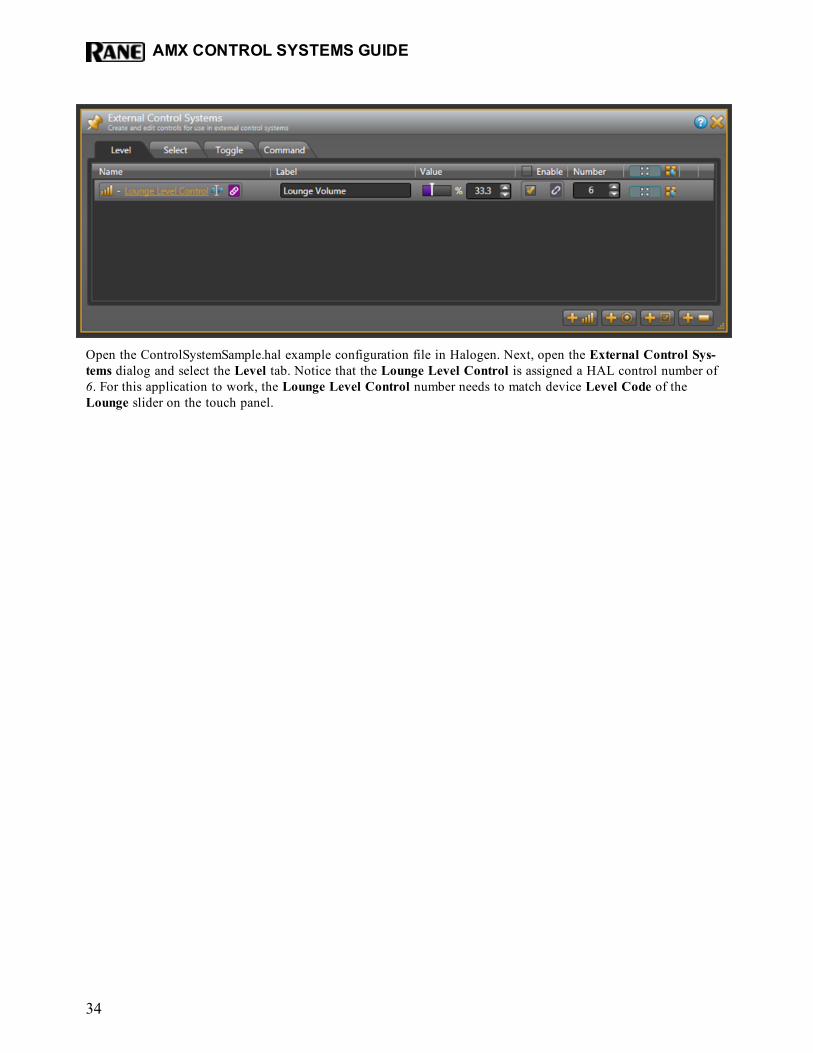
Open the ControlSystemSample.hal example configuration file in Halogen. Next, open the External Control Sys-tems dialog and select the Level tab. Notice that the Lounge Level Control is assigned a HAL control number of6. For this application to work, the Lounge Level Control number needs to match device Level Code of theLounge slider on the touch panel.
AMX CONTROL SYSTEMS GUIDE
34
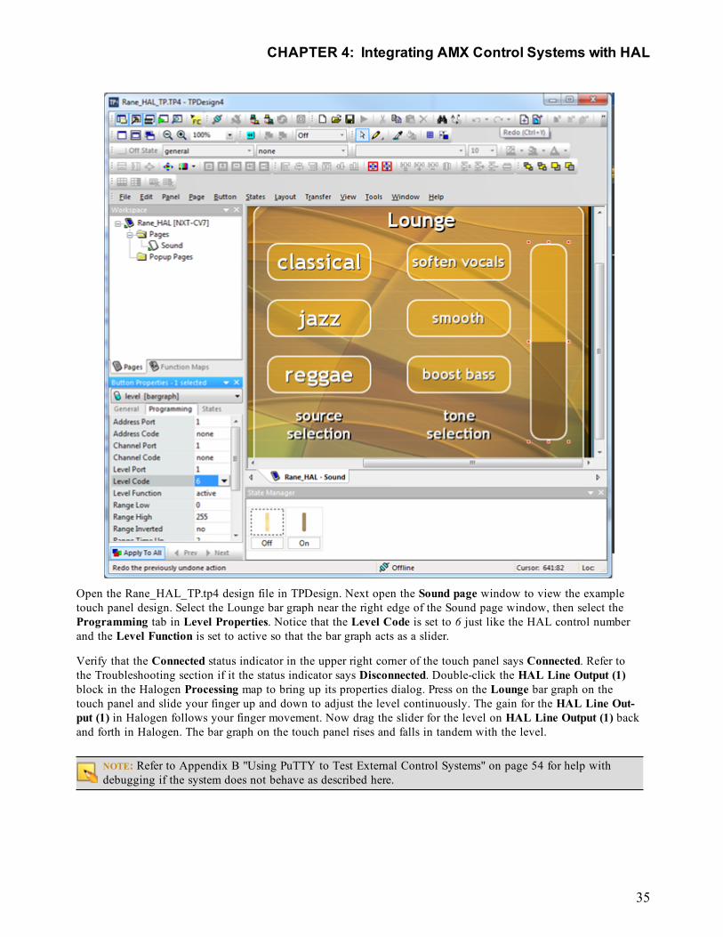
Open the Rane_HAL_TP.tp4 design file in TPDesign. Next open the Sound page window to view the exampletouch panel design. Select the Lounge bar graph near the right edge of the Sound page window, then select theProgramming tab in Level Properties. Notice that the Level Code is set to 6 just like the HAL control numberand the Level Function is set to active so that the bar graph acts as a slider.
Verify that the Connected status indicator in the upper right corner of the touch panel says Connected. Refer tothe Troubleshooting section if it the status indicator says Disconnected. Double-click the HAL Line Output (1)block in the Halogen Processing map to bring up its properties dialog. Press on the Lounge bar graph on thetouch panel and slide your finger up and down to adjust the level continuously. The gain for the HAL Line Out-put (1) in Halogen follows your finger movement. Now drag the slider for the level on HAL Line Output (1) backand forth in Halogen. The bar graph on the touch panel rises and falls in tandem with the level.
NOTE: Refer to Appendix B "Using PuTTY to Test External Control Systems" on page 54 for help withdebugging if the system does not behave as described here.
CHAPTER 4: Integrating AMX Control Systems with HAL
35
SelectorsThis section explains how to integrate HAL selector controls with buttons on an AMX touch panel by examininga couple of touch panel applications: input source selector radio buttons and preset selector radio buttons. We startby dissecting the code for the HAL selector controls and radio buttons. Then we demonstrate how to bind theHAL selector controls to radio buttons in the touch panel user interface.
At its simplest, a HAL selector control is just a selection integer value. The range of this selection value is con-strained by the number of positions on the selector. For instance a HAL three-way selector can only have a valueof 0, 1 or 2. Lets look at one way to code a fixed selector.
Open the Main.axs source file in NetLinx Studio. Find the DEFINE_CONSTANT section of the program. It con-tains some constants for a three-way source selector implemented as three radio buttons:
BTN_CLASSICAL = 10
BTN_JAZZ = 11
BTN_REGGAE = 12
…
nSourceSelNumber = 1
INTEGER nSourceSelChannels[] = { BTN_CLASSICAL, BTN_JAZZ, BTN_REGGAE}
10, 11 and 12 are the device Channel Codes of the source selector’s three touch panel radio buttons. 1 is theunique control number of this source selector on the HAL. Unlike the preceding toggle, command and level code,the selector’s device Channel Codes do not double as HAL control numbers. This is because there is not a one-to-one relationship between radio buttons and a selector controls.
The three-way tone selector has similar constants. BTN_SOFTEN_VOCALS, BTN_SMOOTH and BTN_BOOST_BASS are the device channel numbers of the tone selector’s three radio buttons. 2 is the tone selector’s unique con-trol number on the HAL.
Find the DEFINE_VARIABLE section of the program. It contains some source-selector-related variables:
nSourceSelValue
bSourceSelRadios[max_length_array(nSourceSelChannels)]
The selection value of the source selector is kept in nSourceSelValue. The on/off states of the source selector’sthree radio buttons are maintained in bSourceSelRadios array. We’ll see shortly that the source selector in thisexample is modeled as a collection of mutually exclusive toggles.
The source selector has a dedicated event handler for its touch panel radio buttons. You will need to customize itfor your own fixed selectors:
BUTTON_EVENT[dvTP, nSourceSelChannels]{
AMX CONTROL SYSTEMS GUIDE
36
PUSH:{nChannelIndex = GET_LAST(nSourceSelChannels)
if (nChannelIndex > 0 &&nChannelIndex <= length_array(nSourceSelChannels))
{nSourceSelValue = nChannelIndex - 1
UpdateSourceSelectorRadios(nSourceSelChannels[nChannelIndex])
Send_String dvHAL, "'<S&',itoa(nSourceSelNumber), '&',itoa(nSourceSelValue), '>'"
}}
}
The device Channel Codes for the selector’s three radio buttons are passed in through the nSource-SelChannels argument. The handler knows which radio button on the touch panel fired the event because theGET_LAST call returns the index of that button in the nSourceSelChannels array. It then subtracts 1 fromthat index to get the new selection value. A call to UpdateSourceSelectorRadios ensures the other radiobuttons on the touch panel are toggled off.
Likewise, the tone selector has its own dedicated event handler and UpdateToneSelectorRadios function.The selection value of the tone selector is kept in nToneSelValue. The on/off states of the tone selector’s threeradio buttons are maintained in the bToneSelRadios array.
Whenever a touch panel radio button is pressed, the corresponding selector’s event handler sends a message stringwith a new selection value to the HAL. These ‘set selector’ messages contain a selector control type, HAL controlnumber and value. The valid ‘set selector’ messages for the source selector in this program are <S&1&0>,<S&1&1> and <S&1&2>. The valid ‘set selector’ messages for the tone selector in this program are <S&2&0>,<S&2&1> and <S&2&2>
The HAL sends these same ‘set selector’ messages to the controller whenever another client changes the selectionvalue. Here is the STRING event handler code in the client to parse incoming selection values for both selectors:
active(find_string(cData, '<S&', 1)):{remove_string(cData, '<S&', 1)
nSelectorNumber = atoi(cData)
remove_string(cData, '&', 1)
if (nSelectorNumber == nSourceSelNumber){nSourceSelValue = atoi(cData)
CHAPTER 4: Integrating AMX Control Systems with HAL
37
UpdateSourceSelectorRadios(nSourceSelChannels[nSourceSelValue + 1])
}else if (nSelectorNumber == nToneSelNumber){nToneSelValue = atoi(cData)
UpdateToneSelectorRadios(nToneSelChannels[nToneSelValue + 1])
}
remove_string(cData, '>', 1)}
The Mainline contains feedback statements for the selectors’ radio buttons. These feedback statements update thevisible state of the selectors’ radio buttons on the touch panel in response to selection value changes triggered bybutton presses from the touch panel or messages from the HAL:
for (nChannelIndex = 1;nChannelIndex <= length_array(nSourceSelChannels);nChannelIndex++)
{[dvTP, nSourceSelChannels[nChannelIndex]] =
bSourceSelRadios[nChannelIndex]}
for (nChannelIndex = 1;nChannelIndex <= length_array(nToneSelChannels);nChannelIndex++)
{[dvTP, nToneSelChannels[nChannelIndex]] =
bToneSelRadios[nChannelIndex]}
The controller requests HAL selector control values from the HAL upon connecting. This ensures that the radiobuttons on the touch panel are in sync with the live selector values on the HAL. It does this by sending ‘get selec-tor’ messages to Halogen/HAL when the ONLINE event is fired. These ‘get selector’ messages consist of a selectorcontrol type and HAL control number. See the source selector’s ‘get selector’ message in the client’s ONLINEevent handler.
Send_String dvHAL, "'<S&', itoa(nSourceSelNumber), '>'"
Send_String dvHAL, "'<S&', itoa(nToneSelNumber), '>'"
The valid ‘get selector’ message string for the two selectors in this example are <S&1> and <S&2>. The HALresponds to these ‘get selector’ messages with corresponding ‘set selector’ messages.
AMX CONTROL SYSTEMS GUIDE
38
NOTE: Refer to Appendix A "HAL External Control Message Protocol" on page 44 for more information onselector messages.
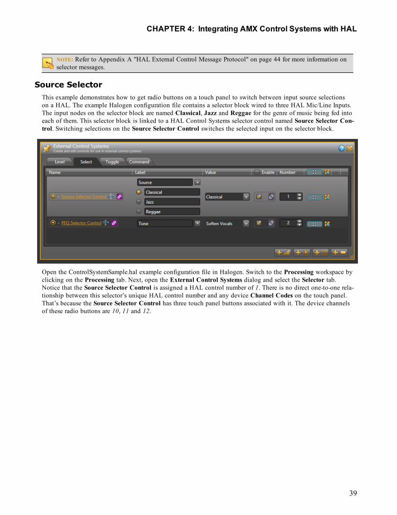
Source SelectorThis example demonstrates how to get radio buttons on a touch panel to switch between input source selectionson a HAL. The example Halogen configuration file contains a selector block wired to three HAL Mic/Line Inputs.The input nodes on the selector block are named Classical, Jazz and Reggae for the genre of music being fed intoeach of them. This selector block is linked to a HAL Control Systems selector control named Source Selector Con-trol. Switching selections on the Source Selector Control switches the selected input on the selector block.
Open the ControlSystemSample.hal example configuration file in Halogen. Switch to the Processing workspace byclicking on the Processing tab. Next, open the External Control Systems dialog and select the Selector tab.Notice that the Source Selector Control is assigned a HAL control number of 1. There is no direct one-to-one rela-tionship between this selector’s unique HAL control number and any device Channel Codes on the touch panel.That’s because the Source Selector Control has three touch panel buttons associated with it. The device channelsof these radio buttons are 10, 11 and 12.
CHAPTER 4: Integrating AMX Control Systems with HAL
39
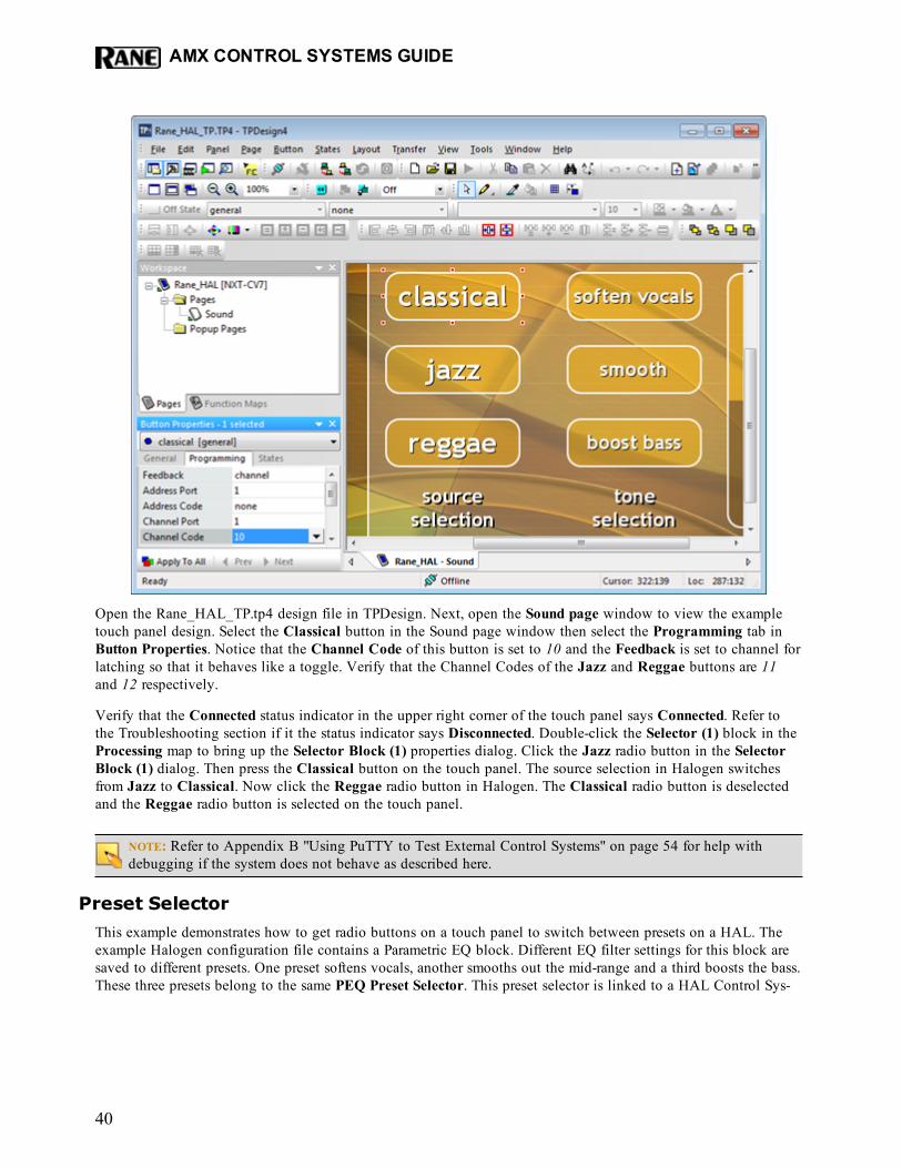
Open the Rane_HAL_TP.tp4 design file in TPDesign. Next, open the Sound page window to view the exampletouch panel design. Select the Classical button in the Sound page window then select the Programming tab inButton Properties. Notice that the Channel Code of this button is set to 10 and the Feedback is set to channel forlatching so that it behaves like a toggle. Verify that the Channel Codes of the Jazz and Reggae buttons are 11and 12 respectively.
Verify that the Connected status indicator in the upper right corner of the touch panel says Connected. Refer tothe Troubleshooting section if it the status indicator says Disconnected. Double-click the Selector (1) block in theProcessing map to bring up the Selector Block (1) properties dialog. Click the Jazz radio button in the SelectorBlock (1) dialog. Then press the Classical button on the touch panel. The source selection in Halogen switchesfrom Jazz to Classical. Now click the Reggae radio button in Halogen. The Classical radio button is deselectedand the Reggae radio button is selected on the touch panel.
NOTE: Refer to Appendix B "Using PuTTY to Test External Control Systems" on page 54 for help withdebugging if the system does not behave as described here.
Preset SelectorThis example demonstrates how to get radio buttons on a touch panel to switch between presets on a HAL. Theexample Halogen configuration file contains a Parametric EQ block. Different EQ filter settings for this block aresaved to different presets. One preset softens vocals, another smooths out the mid-range and a third boosts the bass.These three presets belong to the same PEQ Preset Selector. This preset selector is linked to a HAL Control Sys-
AMX CONTROL SYSTEMS GUIDE
40
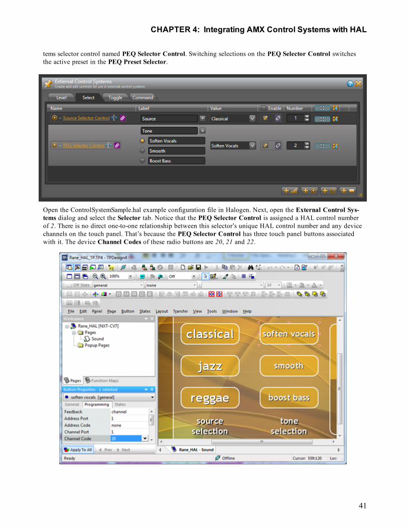
tems selector control named PEQ Selector Control. Switching selections on the PEQ Selector Control switchesthe active preset in the PEQ Preset Selector.
Open the ControlSystemSample.hal example configuration file in Halogen. Next, open the External Control Sys-tems dialog and select the Selector tab. Notice that the PEQ Selector Control is assigned a HAL control numberof 2. There is no direct one-to-one relationship between this selector’s unique HAL control number and any devicechannels on the touch panel. That’s because the PEQ Selector Control has three touch panel buttons associatedwith it. The device Channel Codes of these radio buttons are 20, 21 and 22.
CHAPTER 4: Integrating AMX Control Systems with HAL
41
Open the Rane_HAL_TP.tp4 design file in TPDesign. Next open the Sound page window to view the exampletouch panel design. Select the Soften Vocals button in the Sound page window then select the Programming tabin Button Properties. Notice that the Channel Code of this button is set to 20 and the Feedback is set to channelfor latching so that it behaves like a toggle. Verify that the Channel Codes of the Smooth and Boost Bass buttonsare 21 and 22 respectively.
Verify that the Connected status indicator in the upper right corner of the touch panel says Connected. Refer tothe Troubleshooting section if it the status indicator says Disconnected. Click the Presets icon in the Processingtoolbar to bring up the All Presets dialog. Choose the Selector tab in that dialog and expand the PEQ PresetSelector so that its contents are visible. Click the Smooth radio button in the All Presets dialog. Then click on theSoften Vocals radio button on the touch panel. The selected PEQ preset in Halogen switches from Smooth to Sof-ten Vocals. Now click on the Boost Bass radio button in Halogen. The Boost Bass radio button is selected andthe Soften Vocals radio button is deselected on the touch panel.
NOTE: Refer to Appendix B "Using PuTTY to Test External Control Systems" on page 54 for help withdebugging if the system does not behave as described here.
Troubleshooting1. If you are having problems applying the example design to your touch panel:
l Remember that design files are transferred to an AMX touch panel by way of the controller.l Open the Rane_HAL_TP.tp4 design file in TPDesign.l Select Connect from the Transfer menu to bring up the Connect dialog.l If there is no entry for your controller in the Connect dialog’s connection list add one by
clicking the New button.l Once your controller has a connection in the list, select Send To Panel from the Transfer
menu to transfer the design to the touch panel.l NetLinx Studio provides tools to help with troubleshooting connectivity problems.
l Select Telnet Session from the Tools menu.l Add an entry with your controller’s IP to the List of Addresses in Telnet Settings if one
does not exist.l Select your controller’s address entry and click the OK button to start the telnet session.l Type help from the telnet prompt to see the various command line tools at your disposal.l Verify that your controller has established communications with the control server running
on your PC by entering ip status from the telnet prompt.
AMX CONTROL SYSTEMS GUIDE
42
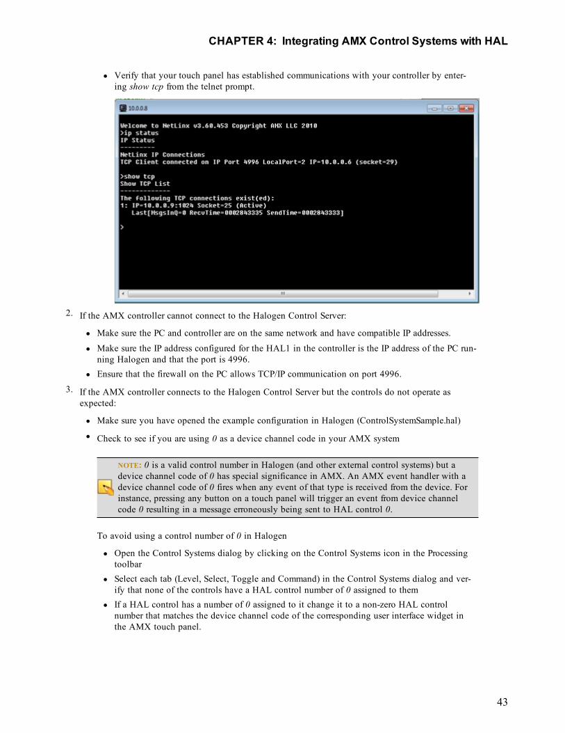
l Verify that your touch panel has established communications with your controller by enter-ing show tcp from the telnet prompt.
2. If the AMX controller cannot connect to the Halogen Control Server:
l Make sure the PC and controller are on the same network and have compatible IP addresses.l Make sure the IP address configured for the HAL1 in the controller is the IP address of the PC run-
ning Halogen and that the port is 4996.l Ensure that the firewall on the PC allows TCP/IP communication on port 4996.
3. If the AMX controller connects to the Halogen Control Server but the controls do not operate asexpected:
l Make sure you have opened the example configuration in Halogen (ControlSystemSample.hal)l Check to see if you are using 0 as a device channel code in your AMX system
NOTE: 0 is a valid control number in Halogen (and other external control systems) but adevice channel code of 0 has special significance in AMX. An AMX event handler with adevice channel code of 0 fires when any event of that type is received from the device. Forinstance, pressing any button on a touch panel will trigger an event from device channelcode 0 resulting in a message erroneously being sent to HAL control 0.
To avoid using a control number of 0 in Halogen
l Open the Control Systems dialog by clicking on the Control Systems icon in the Processingtoolbar
l Select each tab (Level, Select, Toggle and Command) in the Control Systems dialog and ver-ify that none of the controls have a HAL control number of 0 assigned to them
l If a HAL control has a number of 0 assigned to it change it to a non-zero HAL controlnumber that matches the device channel code of the corresponding user interface widget inthe AMX touch panel.
CHAPTER 4: Integrating AMX Control Systems with HAL
43
APPENDIX A: HAL External Control Message ProtocolOnce you have connected to either the Halogen or HAL external control server, you can communicate with itusing simple, text-based messages. This section defines this message protocol.
All messages consist of ASCII text and a single message always starts with a ‘<’ character and ends with a ‘>’ char-acter. Inside the start and end characters is the message body, which always includes at least a message type fol-lowed by a control number. Each part of the message body is separated from another part by an ‘&’ character.Messages can also have additional parts depending on the type of message. The table below shows the format foreach specific message type.
When sending messages to the Halogen/HAL Control Server, it:
l Allows white space anywhere in the message, which includes space, tab, carriage return, and line feed char-acters
l Ignores all characters outside of a message (that is, before the start character and after the end character)l Ignores the case of alpha characters – you can use upper or lower case in any combination
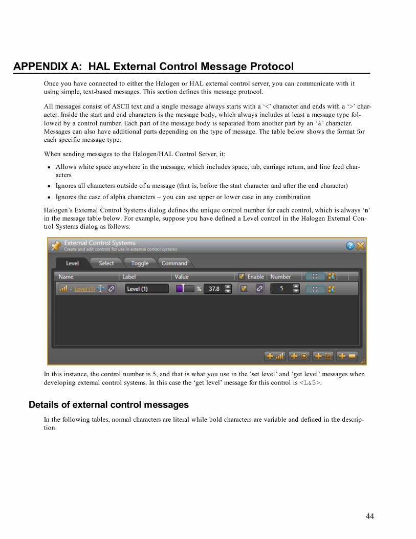
Halogen’s External Control Systems dialog defines the unique control number for each control, which is always ‘n’in the message table below. For example, suppose you have defined a Level control in the Halogen External Con-trol Systems dialog as follows:
In this instance, the control number is 5, and that is what you use in the ‘set level’ and ‘get level’ messages whendeveloping external control systems. In this case the ‘get level’ message for this control is <L&5>.
Details of external control messagesIn the following tables, normal characters are literal while bold characters are variable and defined in the descrip-tion.
44
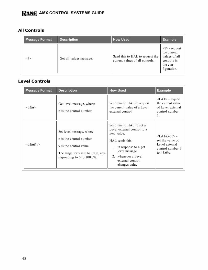
All Controls
Message Format Description How Used Example
<?> Get all values message. Send this to HAL to request thecurrent values of all controls.
<?> - requestthe currentvalues of allcontrols inthe con-figuration.
Level Controls
Message Format Description How Used Example
<L&n>Get level message, where:
n is the control number.
Send this to HAL to requestthe current value of a Levelexternal control.
<L&1> - requestthe current valueof Level externalcontrol number1.
<L&n&v>
Set level message, where:
n is the control number.
v is the control value.
The range for v is 0 to 1000, cor-responding to 0 to 100.0%.
Send this to HAL to set aLevel external control to anew value.
HAL sends this:
1. in response to a getlevel message
2. whenever a Levelexternal controlchanges value
<L&1&456> -set the value ofLevel externalcontrol number 1to 45.6%.
AMX CONTROL SYSTEMS GUIDE
45
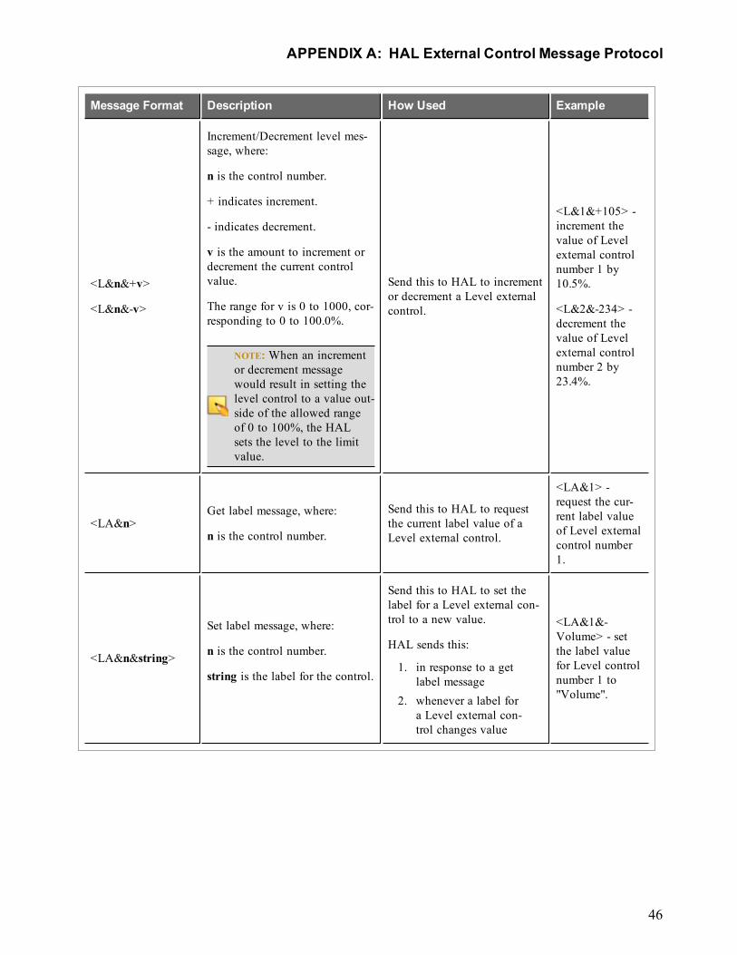
Message Format Description How Used Example
<L&n&+v>
<L&n&-v>
Increment/Decrement level mes-sage, where:
n is the control number.
+ indicates increment.
- indicates decrement.
v is the amount to increment ordecrement the current controlvalue.
The range for v is 0 to 1000, cor-responding to 0 to 100.0%.
NOTE:When an incrementor decrement messagewould result in setting thelevel control to a value out-side of the allowed rangeof 0 to 100%, the HALsets the level to the limitvalue.
Send this to HAL to incrementor decrement a Level externalcontrol.
<L&1&+105> -increment thevalue of Levelexternal controlnumber 1 by10.5%.
<L&2&-234> -decrement thevalue of Levelexternal controlnumber 2 by23.4%.
<LA&n>Get label message, where:
n is the control number.
Send this to HAL to requestthe current label value of aLevel external control.
<LA&1> -request the cur-rent label valueof Level externalcontrol number1.
<LA&n&string>
Set label message, where:
n is the control number.
string is the label for the control.
Send this to HAL to set thelabel for a Level external con-trol to a new value.
HAL sends this:
1. in response to a getlabel message
2. whenever a label fora Level external con-trol changes value
<LA&1&-Volume> - setthe label valuefor Level controlnumber 1 to"Volume".
APPENDIX A: HAL External Control Message Protocol
46
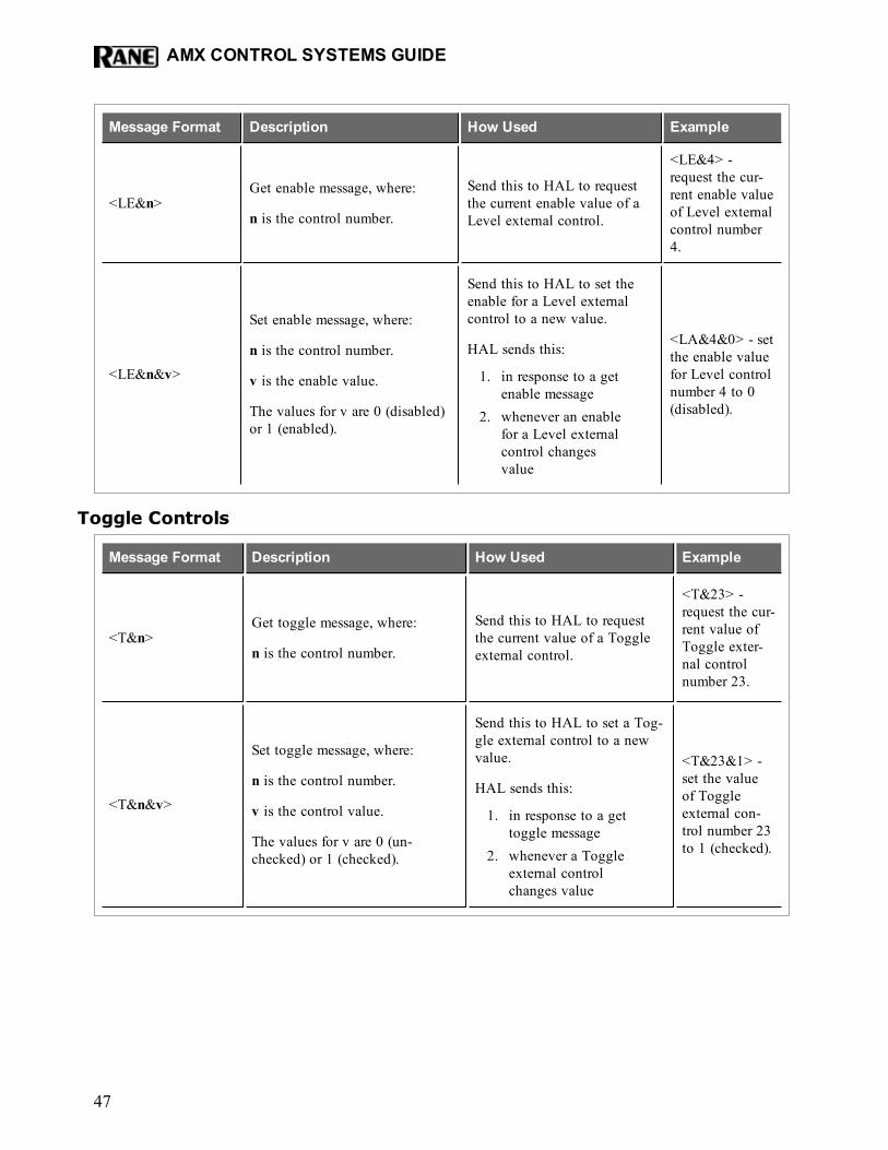
Message Format Description How Used Example
<LE&n>Get enable message, where:
n is the control number.
Send this to HAL to requestthe current enable value of aLevel external control.
<LE&4> -request the cur-rent enable valueof Level externalcontrol number4.
<LE&n&v>
Set enable message, where:
n is the control number.
v is the enable value.
The values for v are 0 (disabled)or 1 (enabled).
Send this to HAL to set theenable for a Level externalcontrol to a new value.
HAL sends this:
1. in response to a getenable message
2. whenever an enablefor a Level externalcontrol changesvalue
<LA&4&0> - setthe enable valuefor Level controlnumber 4 to 0(disabled).
Toggle Controls
Message Format Description How Used Example
<T&n>Get toggle message, where:
n is the control number.
Send this to HAL to requestthe current value of a Toggleexternal control.
<T&23> -request the cur-rent value ofToggle exter-nal controlnumber 23.
<T&n&v>
Set toggle message, where:
n is the control number.
v is the control value.
The values for v are 0 (un-checked) or 1 (checked).
Send this to HAL to set a Tog-gle external control to a newvalue.
HAL sends this:
1. in response to a gettoggle message
2. whenever a Toggleexternal controlchanges value
<T&23&1> -set the valueof Toggleexternal con-trol number 23to 1 (checked).
AMX CONTROL SYSTEMS GUIDE
47
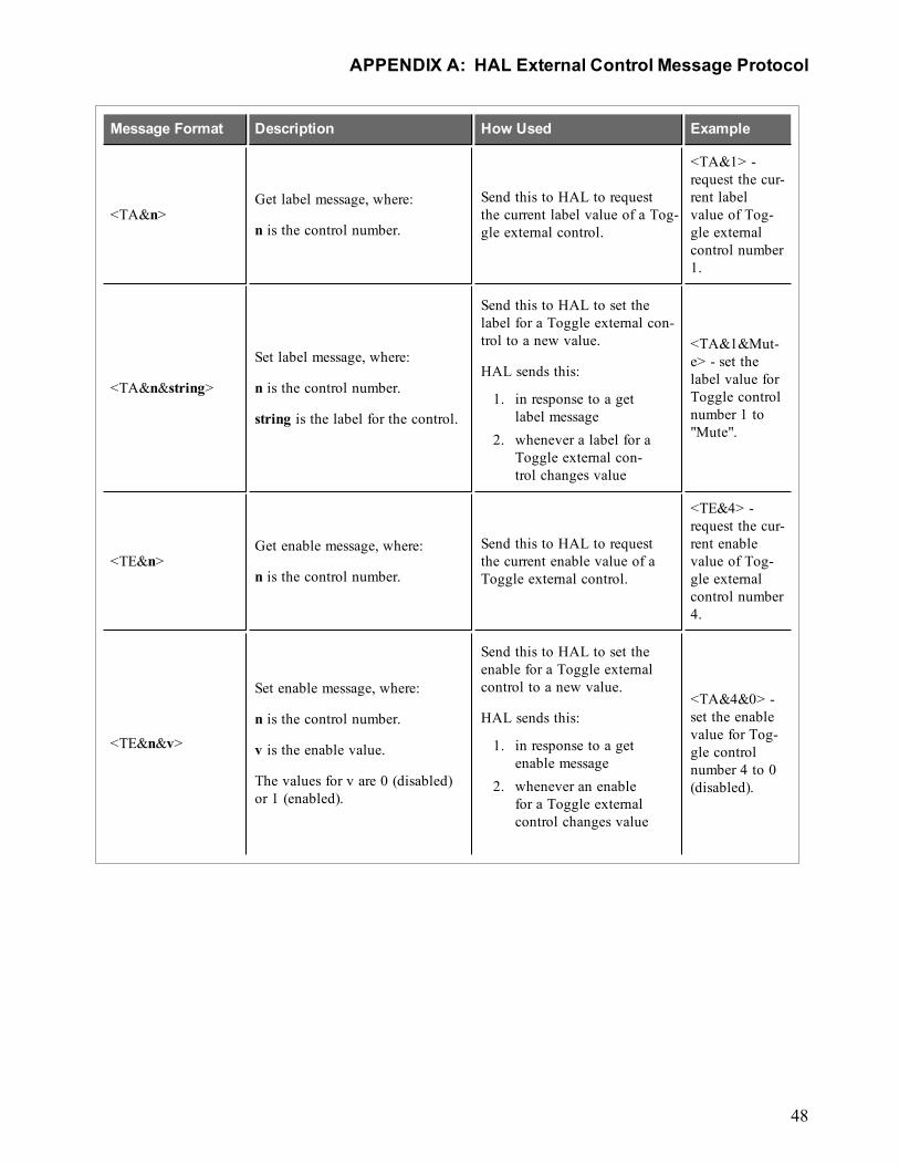
Message Format Description How Used Example
<TA&n>Get label message, where:
n is the control number.
Send this to HAL to requestthe current label value of a Tog-gle external control.
<TA&1> -request the cur-rent labelvalue of Tog-gle externalcontrol number1.
<TA&n&string>
Set label message, where:
n is the control number.
string is the label for the control.
Send this to HAL to set thelabel for a Toggle external con-trol to a new value.
HAL sends this:
1. in response to a getlabel message
2. whenever a label for aToggle external con-trol changes value
<TA&1&Mut-e> - set thelabel value forToggle controlnumber 1 to"Mute".
<TE&n>Get enable message, where:
n is the control number.
Send this to HAL to requestthe current enable value of aToggle external control.
<TE&4> -request the cur-rent enablevalue of Tog-gle externalcontrol number4.
<TE&n&v>
Set enable message, where:
n is the control number.
v is the enable value.
The values for v are 0 (disabled)or 1 (enabled).
Send this to HAL to set theenable for a Toggle externalcontrol to a new value.
HAL sends this:
1. in response to a getenable message
2. whenever an enablefor a Toggle externalcontrol changes value
<TA&4&0> -set the enablevalue for Tog-gle controlnumber 4 to 0(disabled).
APPENDIX A: HAL External Control Message Protocol
48
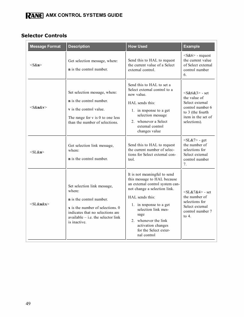
Selector Controls
Message Format Description How Used Example
<S&n>Get selection message, where:
n is the control number.
Send this to HAL to requestthe current value of a Selectexternal control.
<S&6> - requestthe current valueof Select externalcontrol number6.
<S&n&v>
Set selection message, where:
n is the control number.
v is the control value.
The range for v is 0 to one lessthan the number of selections.
Send this to HAL to set aSelect external control to anew value.
HAL sends this:
1. in response to a getselection message
2. whenever a Selectexternal controlchanges value
<S&6&3> - setthe value ofSelect externalcontrol number 6to 3 (the fourthitem in the set ofselections).
<SL&n>Get selection link message,where:
n is the control number.
Send this to HAL to requestthe current number of selec-tions for Select external con-trol.
<SL&7> - getthe number ofselections forSelect externalcontrol number7.
<SL&n&x>
Set selection link message,where:
n is the control number.
x is the number of selections. 0indicates that no selections areavailable – i.e. the selector linkis inactive.
It is not meaningful to sendthis message to HAL becausean external control system can-not change a selection link.
HAL sends this:
1. in response to a getselection link mes-sage
2. whenever the linkactivation changesfor the Select exter-nal control
<SL&7&4> - setthe number ofselections forSelect externalcontrol number 7to 4.
AMX CONTROL SYSTEMS GUIDE
49
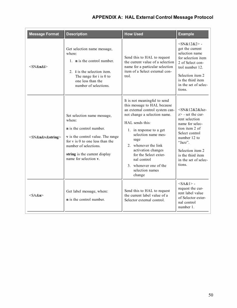
Message Format Description How Used Example
<SN&n&i>
Get selection name message,where:
1. n is the control number.
2. i is the selection item.The range for i is 0 toone less than thenumber of selections.
Send this to HAL to requestthe current value of a selectionname for a particular selectionitem of a Select external con-trol.
<SN&12&2> -get the currentselection namefor selection item2 of Select con-trol number 12.
Selection item 2is the third itemin the set of selec-tions.
<SN&n&v&string>
Set selection name message,where:
n is the control number.
v is the control value. The rangefor v is 0 to one less than thenumber of selections.
string is the current displayname for selection v.
It is not meaningful to sendthis message to HAL becausean external control system can-not change a selection name.
HAL sends this:
1. in response to a getselection name mes-sage
2. whenever the linkactivation changesfor the Select exter-nal control
3. whenever one of theselection nameschange
<SN&12&2&Jaz-z> - set the cur-rent selectionname for selec-tion item 2 ofSelect controlnumber 12 to“Jazz”.
Selection item 2is the third itemin the set of selec-tions.
<SA&n>Get label message, where:
n is the control number.
Send this to HAL to requestthe current label value of aSelector external control.
<SA&1> -request the cur-rent label valueof Selector exter-nal controlnumber 1.
APPENDIX A: HAL External Control Message Protocol
50
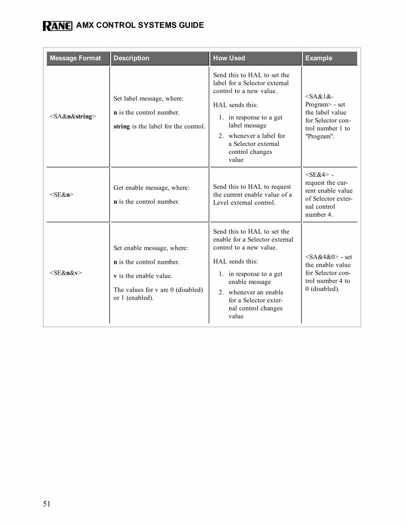
Message Format Description How Used Example
<SA&n&string>
Set label message, where:
n is the control number.
string is the label for the control.
Send this to HAL to set thelabel for a Selector externalcontrol to a new value.
HAL sends this:
1. in response to a getlabel message
2. whenever a label fora Selector externalcontrol changesvalue
<SA&1&-Program> - setthe label valuefor Selector con-trol number 1 to"Program".
<SE&n>Get enable message, where:
n is the control number.
Send this to HAL to requestthe current enable value of aLevel external control.
<SE&4> -request the cur-rent enable valueof Selector exter-nal controlnumber 4.
<SE&n&v>
Set enable message, where:
n is the control number.
v is the enable value.
The values for v are 0 (disabled)or 1 (enabled).
Send this to HAL to set theenable for a Selector externalcontrol to a new value.
HAL sends this:
1. in response to a getenable message
2. whenever an enablefor a Selector exter-nal control changesvalue
<SA&4&0> - setthe enable valuefor Selector con-trol number 4 to0 (disabled).
AMX CONTROL SYSTEMS GUIDE
51
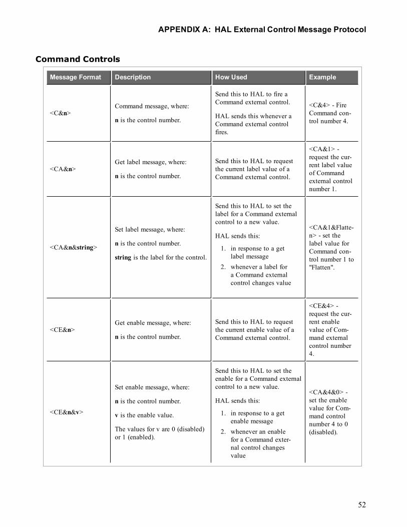
Command Controls
Message Format Description How Used Example
<C&n>Command message, where:
n is the control number.
Send this to HAL to fire aCommand external control.
HAL sends this whenever aCommand external controlfires.
<C&4> - FireCommand con-trol number 4.
<CA&n>Get label message, where:
n is the control number.
Send this to HAL to requestthe current label value of aCommand external control.
<CA&1> -request the cur-rent label valueof Commandexternal controlnumber 1.
<CA&n&string>
Set label message, where:
n is the control number.
string is the label for the control.
Send this to HAL to set thelabel for a Command externalcontrol to a new value.
HAL sends this:
1. in response to a getlabel message
2. whenever a label fora Command externalcontrol changes value
<CA&1&Flatte-n> - set thelabel value forCommand con-trol number 1 to"Flatten".
<CE&n>Get enable message, where:
n is the control number.
Send this to HAL to requestthe current enable value of aCommand external control.
<CE&4> -request the cur-rent enablevalue of Com-mand externalcontrol number4.
<CE&n&v>
Set enable message, where:
n is the control number.
v is the enable value.
The values for v are 0 (disabled)or 1 (enabled).
Send this to HAL to set theenable for a Command externalcontrol to a new value.
HAL sends this:
1. in response to a getenable message
2. whenever an enablefor a Command exter-nal control changesvalue
<CA&4&0> -set the enablevalue for Com-mand controlnumber 4 to 0(disabled).
APPENDIX A: HAL External Control Message Protocol
52
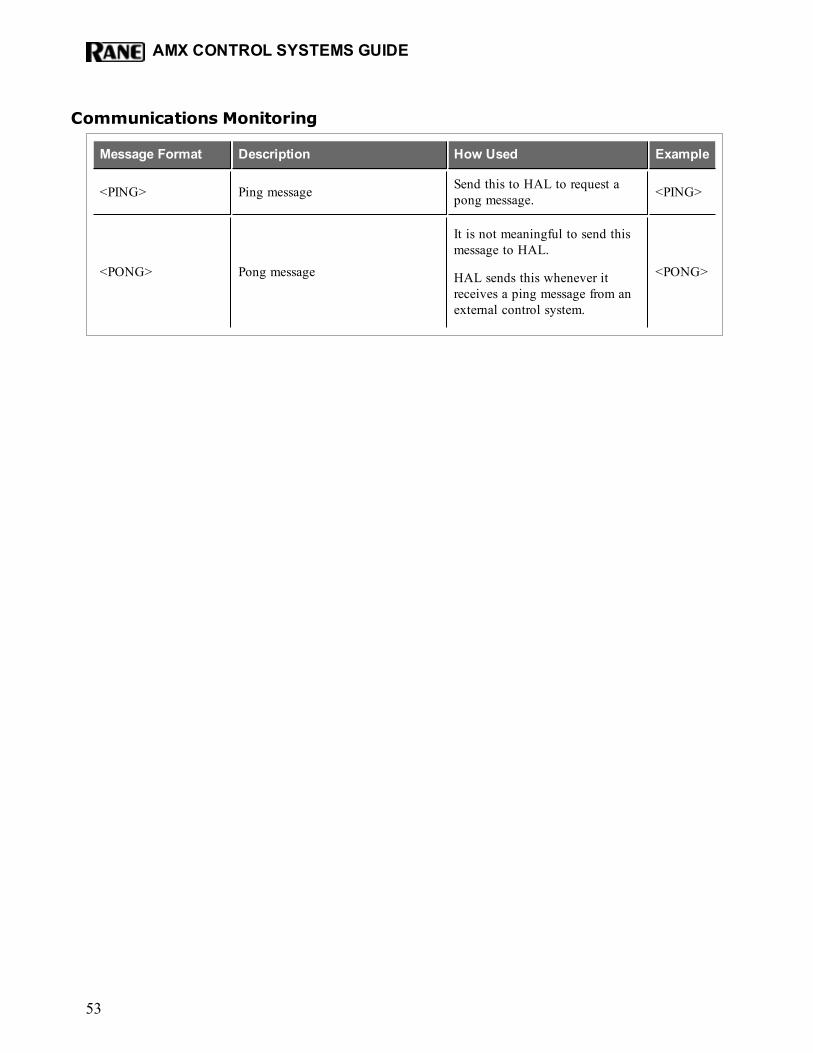
Communications Monitoring
Message Format Description How Used Example
<PING> Ping message Send this to HAL to request apong message. <PING>
<PONG> Pong message
It is not meaningful to send thismessage to HAL.
HAL sends this whenever itreceives a ping message from anexternal control system.
<PONG>
AMX CONTROL SYSTEMS GUIDE
53
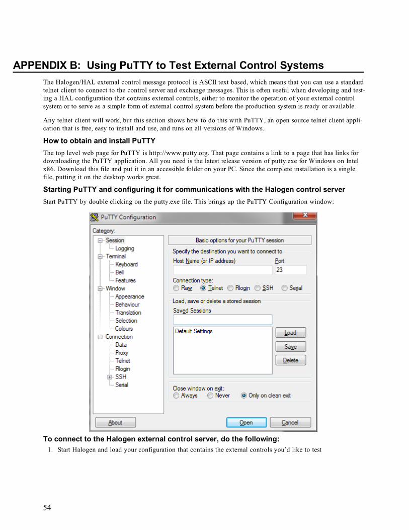
APPENDIX B: Using PuTTY to Test External Control SystemsThe Halogen/HAL external control message protocol is ASCII text based, which means that you can use a standardtelnet client to connect to the control server and exchange messages. This is often useful when developing and test-ing a HAL configuration that contains external controls, either to monitor the operation of your external controlsystem or to serve as a simple form of external control system before the production system is ready or available.
Any telnet client will work, but this section shows how to do this with PuTTY, an open source telnet client appli-cation that is free, easy to install and use, and runs on all versions of Windows.
How to obtain and install PuTTYThe top level web page for PuTTY is http://www.putty.org. That page contains a link to a page that has links fordownloading the PuTTY application. All you need is the latest release version of putty.exe for Windows on Intelx86. Download this file and put it in an accessible folder on your PC. Since the complete installation is a singlefile, putting it on the desktop works great.
Starting PuTTY and configuring it for communications with the Halogen control serverStart PuTTY by double clicking on the putty.exe file. This brings up the PuTTY Configuration window:
To connect to the Halogen external control server, do the following:1. Start Halogen and load your configuration that contains the external controls you’d like to test
54
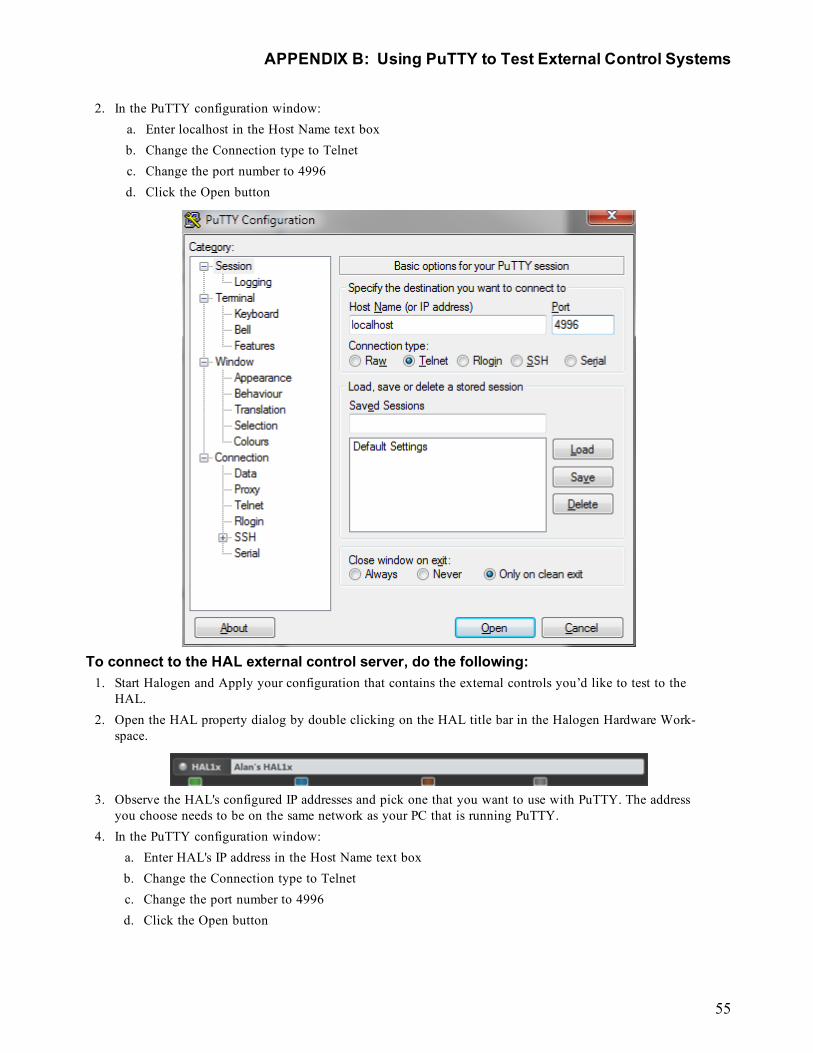
2. In the PuTTY configuration window:a. Enter localhost in the Host Name text boxb. Change the Connection type to Telnetc. Change the port number to 4996d. Click the Open button
To connect to the HAL external control server, do the following:1. Start Halogen and Apply your configuration that contains the external controls you’d like to test to the
HAL.2. Open the HAL property dialog by double clicking on the HAL title bar in the Halogen Hardware Work-
space.
3. Observe the HAL's configured IP addresses and pick one that you want to use with PuTTY. The addressyou choose needs to be on the same network as your PC that is running PuTTY.
4. In the PuTTY configuration window:a. Enter HAL's IP address in the Host Name text boxb. Change the Connection type to Telnetc. Change the port number to 4996d. Click the Open button
APPENDIX B: Using PuTTY to Test External Control Systems
55
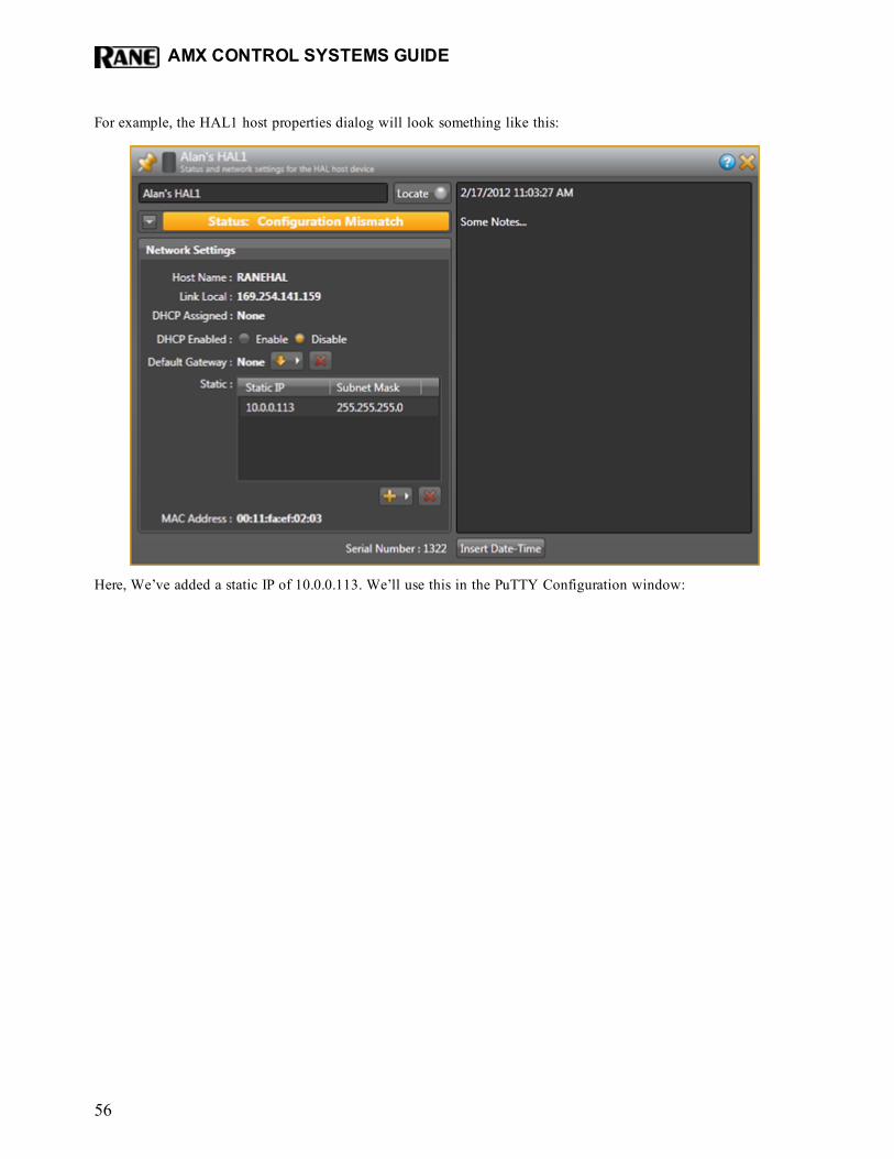
For example, the HAL1 host properties dialog will look something like this:
Here, We’ve added a static IP of 10.0.0.113. We’ll use this in the PuTTY Configuration window:
AMX CONTROL SYSTEMS GUIDE
56
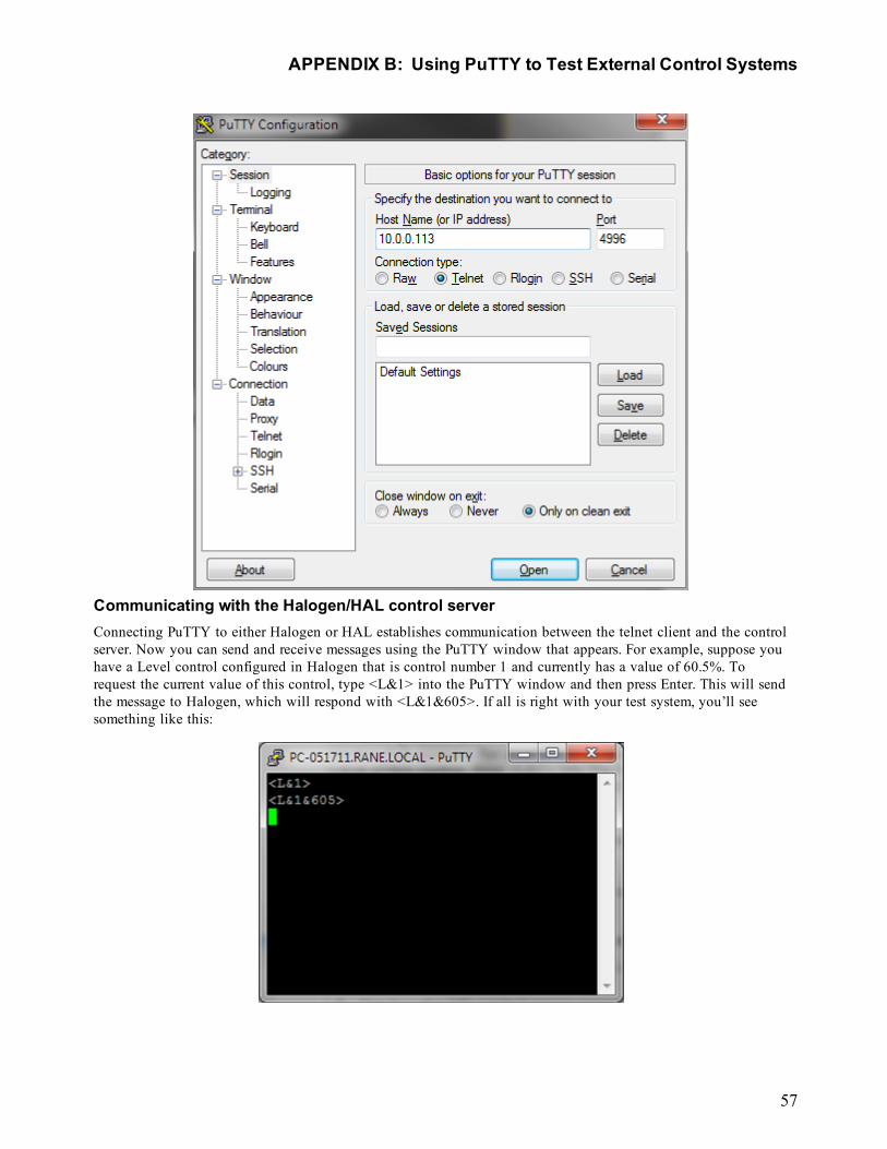
Communicating with the Halogen/HAL control serverConnecting PuTTY to either Halogen or HAL establishes communication between the telnet client and the controlserver. Now you can send and receive messages using the PuTTY window that appears. For example, suppose youhave a Level control configured in Halogen that is control number 1 and currently has a value of 60.5%. Torequest the current value of this control, type <L&1> into the PuTTY window and then press Enter. This will sendthe message to Halogen, which will respond with <L&1&605>. If all is right with your test system, you’ll seesomething like this:
APPENDIX B: Using PuTTY to Test External Control Systems
57
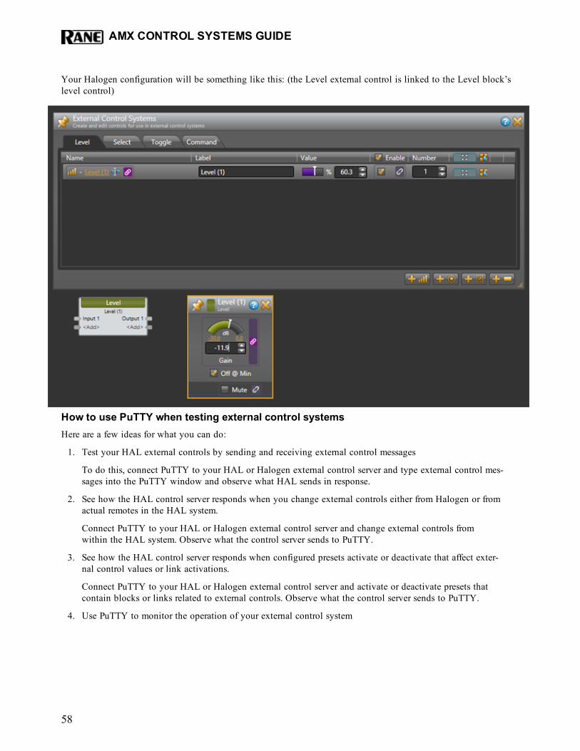
Your Halogen configuration will be something like this: (the Level external control is linked to the Level block’slevel control)
How to use PuTTY when testing external control systemsHere are a few ideas for what you can do:
1. Test your HAL external controls by sending and receiving external control messages
To do this, connect PuTTY to your HAL or Halogen external control server and type external control mes-sages into the PuTTY window and observe what HAL sends in response.
2. See how the HAL control server responds when you change external controls either from Halogen or fromactual remotes in the HAL system.
Connect PuTTY to your HAL or Halogen external control server and change external controls fromwithin the HAL system. Observe what the control server sends to PuTTY.
3. See how the HAL control server responds when configured presets activate or deactivate that affect exter-nal control values or link activations.
Connect PuTTY to your HAL or Halogen external control server and activate or deactivate presets thatcontain blocks or links related to external controls. Observe what the control server sends to PuTTY.
4. Use PuTTY to monitor the operation of your external control system
AMX CONTROL SYSTEMS GUIDE
58
You can connect any number of external control clients to a Halogen or HAL Control Server. This meansthat when you are developing and testing your control system with a commercial product, such as anAMX system, you can also connect to the control server using PuTTY.
NOTE: This lets you monitor most of the interaction between your external control system and yourHalogen/HAL Control Server. This works because when external controls change, the Hal-ogen/HAL Control Server sends these changes to all connected external control clients. So, whenyour external controller changes a control on the HAL, the HAL control server sends the change toyour PuTTY client.
To use PuTTY in this way, first connect PuTTY to the Halogen/HAL Control Server that you want tomonitor. Next connect your control system to the same Halogen/HAL Control Server. As your externalcontrol system interacts with the HAL system, external control messages will appear in the PuTTY win-dow, giving you information about the operation of your external control system.
APPENDIX B: Using PuTTY to Test External Control Systems
59
HALAMX Control Systems Guide
©Rane Corporation 10802 47th Ave. W., Mukilteo WA 98275-5000 USA TEL 425-355-6000 FAX 425-347-7757 WEB rane.com
AMX® and the AMX logo are registered trademarks of AMX.Stardraw Control is a trademark of Stardraw.com Ltd.Crestron® is a registered trademark of Crestron Electronics, Inc.Lexan® is a registered trademark of General Electric.Decora® is a registered trademark of Leviton.Windows® is a registered trademark of Microsoft Corporation in the United States and other countries.Apple, Mac, Macintosh, iTunes, Safari, QuickTime, GarageBand, and OS X are registered trademarks of Apple Inc., registered in the U.S. and other countries.Halogen is a trademark of Rane Corporation.