Embed Size (px)
Citation preview
Contents
Principal Features 3
High Temperature Resistance 4
Oxidation Resistance 7
Chloridation Resistance 8
Carburization Resistance 9
Nitriding Resistance 10
Waste Incineration Environments 11
Tensile Properties 13
Creep and Stress-Rupture 14
Physical Properties 15
Physical Metallurgy 17
Thermal Stability 17
Corrosion Resistance 18
Welding 19
Machining 21
Health and Safety Information 22
Applications 2, 23
HIGH-TEMPERATURE ALLOYS
A solid-solution-strengthened,high-temperature corrosion-resistant alloy that providesexcellent resistance tosulfidation and chloride attackin both reducing and oxidizingatmospheres with exception-ally good resistance to oxida-tion, hot corrosion, carburiza-tion, metal dusting, andnitridation.
H-3129A
HAYNES® HR-160® alloy
2HAYNES HR-160 alloy
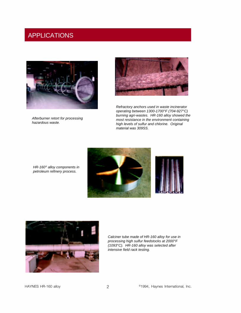
APPLICATIONS
HR-160® alloy components inpetroleum refinery process.
Afterburner retort for processinghazardous waste.
Calciner tube made of HR-160 alloy for use inprocessing high sulfur feedstocks at 2000°F(1093°C). HR-160 alloy was selected afterintensive field rack testing.
©1994, Haynes International, Inc.
Refractory anchors used in waste incineratoroperating between 1300-1700°F (704-927°C)burning agri-wastes. HR-160 alloy showed themost resistance in the environment containinghigh levels of sulfur and chlorine. Originalmaterial was 309SS.
3 HAYNES HR-160 alloy
PRINCIPAL FEATURES
Resistance to High-Temperature CorrosionHAYNES® HR-160® alloy is asolid-solution-strengthenednickel-cobalt-chromium-siliconalloy with outstanding resis-tance to various forms of high-temperature corrosion attack.HR-160 alloy has excellentresistance to sulfidation andchloride attack in both reducingand oxidizing atmospheres.The alloy also has exceptionallygood resistance to oxidation,hot corrosion, carburization,metal dusting, nitridation andcorrosion attack by low meltingpoint compounds such as thoseformed by phosphorus, vana-dium, and other impurities. Thealloy is especially suited forapplications in high temperaturecorrosive environments gener-ated by combustion of low-grade fuels or processing ofchemical feedstocks withcorrosive contaminants such assulfur, chlorine, fluorine, vana-dium, phosphorus, and others.The alloy is capable of with-standing temperatures up to2200°F (1204°C).
Ease of FabricationHAYNES HR-160 alloy hasexcellent forming and weldingcharacteristics. It may beforged or otherwise hot-worked,
providing it is held at 2050°F(1121°C) for time sufficient tobring the entire piece to tem-perature. As a consequence ofits good ductility, HR-160 alloyis also readily formed by coldworking. Cold- or hot-workedparts should be annealed andrapidly cooled in order torestore the best balance ofproperties.
HR-160 alloy can be welded bya variety of techniques, includ-ing gas tungsten arc (TIG), gasmetal arc (MIG), and resistancewelding.
Heat-TreatmentHR-160 alloy is furnished in thesolution annealed condition,unless otherwise specified. Thealloy is solution annealed at2050°F (1121°C) and rapidlycooled for optimum properties.Intermediate annealing, ifrequired during fabrication andforming operations, can beperformed at temperatures aslow as 1950°F (1066°C).
Available in PracticalProduct FormsHAYNES HR-160 alloy isavailable in the form of plate,sheet, strip, billet, bar, wire,pipe and tubing.
ApplicationsHAYNES HR-160 alloy com-bines properties which make ithighly useful for service insevere high-temperaturecorrosive environments. Appli-cations include a variety offabricated components inmunicipal, industrial, hazard-ous, and nuclear waste incin-erators. It is widely used inrecuperators, heat exchangersand waste heat recoverysystems. HR-160 alloy is alsosuitable for utility boilers, sulfurplants, high-temperaturefurnaces, kilns, calciners,resource recovery units, cementkilns, pulp and paper recoveryboilers, coal gasification sys-tems, and fluidized-bed com-bustion systems.
Applicable SpecificationsThe UNS number for HaynesHR-160 alloy is N12160.
ASME Vessel CodeHAYNES HR-160 alloy iscovered by ASME Vessel Codecase No. 2162 for Section VIIIDivision 1 construction to1500°F (816°C).
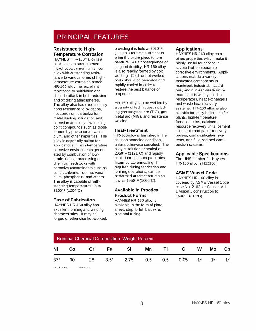
Ni Co Cr Fe Si Mn Ti C W Mo Cb
37a 30 28 3.5* 2.75 0.5 0.5 0.05 1* 1* 1*a As Balance * Maximum
Nominal Chemical Composition, Weight Percent
4HAYNES HR-160 alloy
HIGH TEMPERATURE CORROSION RESISTANCE
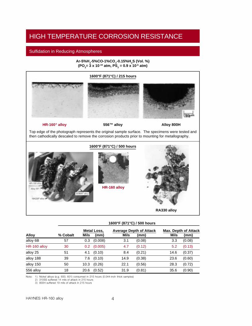
Ar-5%H2-5%CO-1%CO2-0.15%H2S (Vol. %)(PO2= 3 x 10-19 atm, PS2 = 0.9 x 10⁻⁶ atm)
Sulfidation in Reducing Atmospheres
1600°F (871°C) / 215 hours
RA330 alloy
1600°F (871°C) / 500 hours
Max. Depth of AttackMils (mm)3.3 (0.08)
5.2 (0.13)
14.6 (0.37)
23.6 (0.60)
28.3 (0.72)
35.6 (0.90)
Average Depth of AttackMils (mm)3.1 (0.08)
4.7 (0.12)
8.4 (0.21)
14.9 (0.38)
22.1 (0.56)
31.9 (0.81)
Metal Loss, Mils (mm)
0.3 (0.008)
0.2 (0.005)
4.1 (0.10)
7.6 (0.10)
10.3 (0.26)
20.6 (0.52)
Alloyalloy 6B
HR-160 alloy
alloy 25
alloy 188
alloy 150
556 alloy
% Cobalt57
30
51
39
50
18
Note: 1 ) Nickel alloys (e.g. 600, 601) consumed in 215 hours (0.044-inch thick samples)2 ) 310SS suffered 14 mils of attack in 215 hours3 ) 800H suffered 19 mils of attack in 215 hours
1600°F (871°C) / 500 hours
Top edge of the photograph represents the original sample surface. The specimens were tested andthen cathodically descaled to remove the corrosion products prior to mounting for metallography.
HR-160 alloy
556™ alloyHR-160® alloy Alloy 800H
1100°F (593°C) mpy (mm/y)
14.4 (0.37)
23.6 (0.60)
37.7 (0.96)
94.1 (2.39)
150.5 (3.82)
121.1 (3.08)
5 HAYNES HR-160 alloy
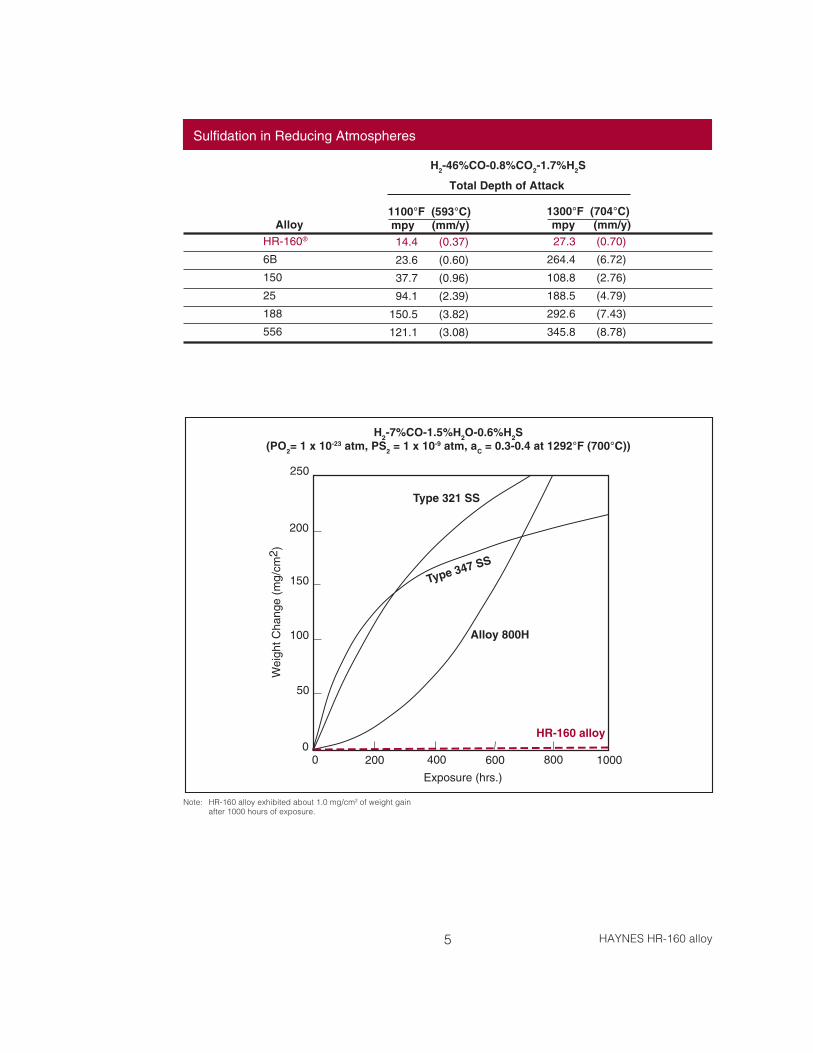
H2-7%CO-1.5%H2O-0.6%H2S(PO2= 1 x 10-23 atm, PS2 = 1 x 10⁻⁹ atm, aC = 0.3-0.4 at 1292°F (700°C))
Note: HR-160 alloy exhibited about 1.0 mg/cm2 of weight gainafter 1000 hours of exposure.
Type 321 SS
Alloy 800H
Type 347 SS
250
200
150
100
50
02000 600400 1000800
Exposure (hrs.)
Wei
ght C
hang
e (m
g/cm
2 )
HR-160 alloy
Sulfidation in Reducing Atmospheres
Total Depth of Attack
1300°F (704°C)mpy (mm/y)27.3 (0.70)
264.4 (6.72)
108.8 (2.76)
188.5 (4.79)
292.6 (7.43)
345.8 (8.78)
AlloyHR-160®
6B
150
25
188
556
H2-46%CO-0.8%CO2-1.7%H2S
6HAYNES HR-160 alloy
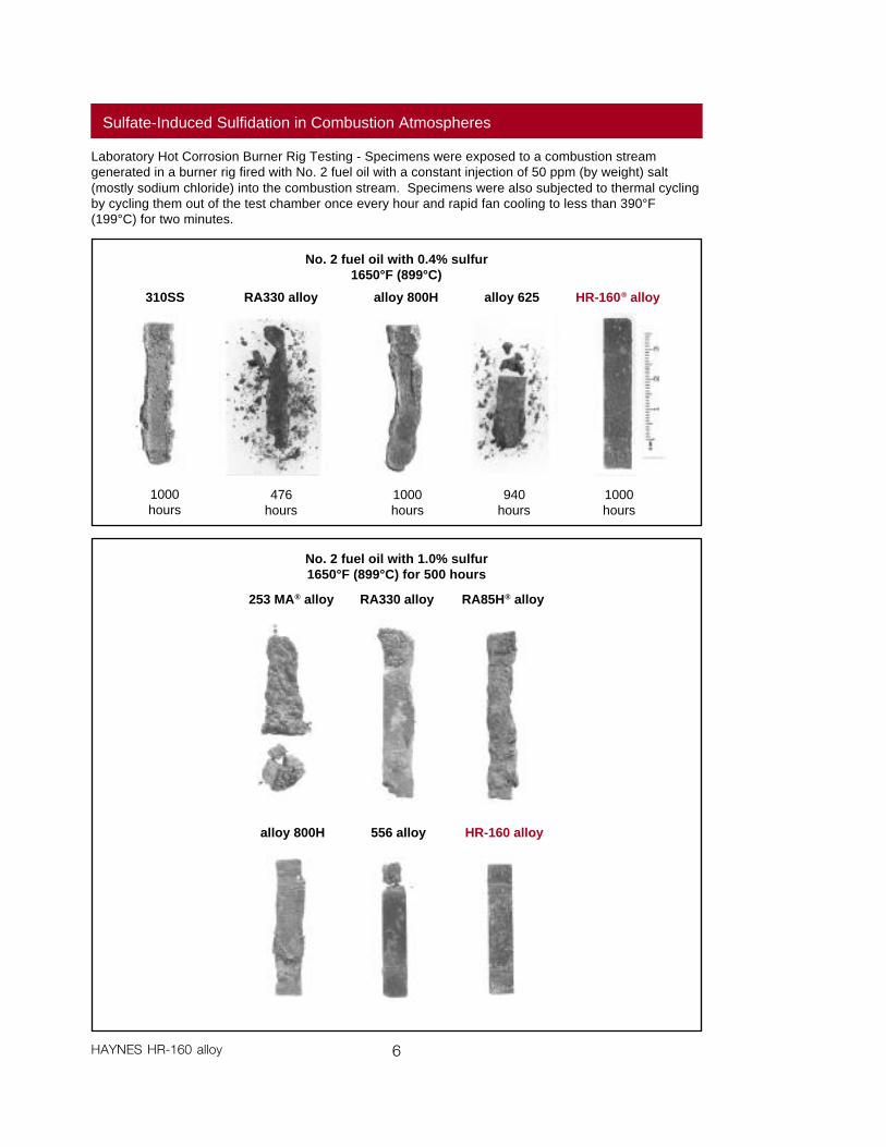
Laboratory Hot Corrosion Burner Rig Testing - Specimens were exposed to a combustion streamgenerated in a burner rig fired with No. 2 fuel oil with a constant injection of 50 ppm (by weight) salt(mostly sodium chloride) into the combustion stream. Specimens were also subjected to thermal cyclingby cycling them out of the test chamber once every hour and rapid fan cooling to less than 390°F(199°C) for two minutes.
No. 2 fuel oil with 1.0% sulfur1650°F (899°C) for 500 hours
alloy 800H 556 alloy HR-160 alloy
253 MA® alloy RA330 alloy RA85H® alloy
Sulfate-Induced Sulfidation in Combustion Atmospheres
310SS RA330 alloy alloy 800H alloy 625 HR-160® alloy
1000hours
476hours
1000hours
940hours
1000hours
No. 2 fuel oil with 0.4% sulfur1650°F (899°C)
7 HAYNES HR-160 alloy
OXIDATION RESISTANCE
Laboratory tests were conducted in flowing air at 1800 to 2200°F (982 to 1204°C) for 1008 hours, withspecimens cycled to room temperature once every 168 hours.
1800°F (982°C)
Metal LossMils*1.7
6.1
0.7
2.9
2100°F (1149°C) 2200°F (1204°C)
AlloyHR-160 alloy
800HT alloy
253 MA alloy
RA85H alloy
Oxidation in Air
2000°F (1093°C)
Metal Loss,Mils*2.7
12.3
8.4
3.7
* To convert mils to mm, divide by 40** Internal oxidation through thickness
Metal LossMils*4.1
19.4
18.6
3.9
Metal Loss,Mils*0.6
0.0
1.3
0.5
AlloyHR-160® alloy
800HT® alloy
253 MA alloy
RA85H alloy
Average MetalAffected, Mils*
13.0
18.8
16.4
>59**
Average MetalAffected, Mils*
5.9
3.9
2.9
8.2
Average MetalAffected, Mils*
10.3
12.0
8.2
25.9
Average MetalAffected, Mils*
24.2
>58*
29.2
>59**
Laboratory tests were conducted at 2000°F (1093°C) in still air (box furnace), with specimens beingcycled to room temperature once every 30 days.
AlloyHR-160 alloy
alloy 601
800HT alloy
RA85H alloy
Long-Term Oxidation in Air
Average Metal*Affected, Mils
29.0
45.1
51.0
80.3
Weight Loss (mg/cm 2)
30days10.4
4.6
4.6
6.3
90days23.2
15.8
203.3
46.5
150days34.6
28.2
379.7
103.8
210days46.8
46.1
529.2
144.9
300days60.1
82.0
746.7
210.5
360days73.1
110.5
893.9
348.1
Metal Loss*Mils3.6
5.4
44.3
17.9
* 360 days
8HAYNES HR-160 alloy
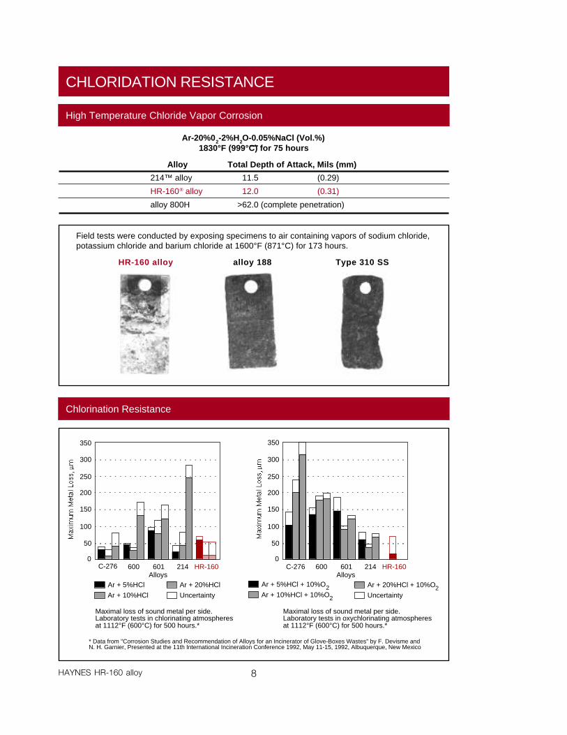
Chlorination Resistance
C-276 600 601 214 HR-1600
50
100
150
200
250
300
350
Ar + 5%HClAlloys
Ar + 10%HCl
Ar + 20%HCl
Uncertainty
Maximal loss of sound metal per side.Laboratory tests in chlorinating atmospheresat 1112°F (600°C) for 500 hours.*
C-276 600 601 214 HR-1600
50
100
150
200
250
300
350
Ar + 5%HCl + 10%O2
Alloys
Ar + 10%HCl + 10%O2
Ar + 20%HCl + 10%O2Uncertainty
Maximal loss of sound metal per side.Laboratory tests in oxychlorinating atmospheresat 1112°F (600°C) for 500 hours.*
* Data from "Corrosion Studies and Recommendation of Alloys for an Incinerator of Glove-Boxes Wastes" by F. Devisme andN. H. Garnier, Presented at the 11th International Incineration Conference 1992, May 11-15, 1992, Albuquerque, New Mexico
CHLORIDATION RESISTANCE
High Temperature Chloride Vapor Corrosion
Ar-20%02-2%H2O-0.05%NaCl (Vol.%)1830°F (999°C) for 75 hours
Total Depth of Attack, Mils (mm)
11.5 (0.29)
12.0 (0.31)
>62.0 (complete penetration)
Alloy
214™ alloy
HR-160® alloy
alloy 800H
Field tests were conducted by exposing specimens to air containing vapors of sodium chloride,potassium chloride and barium chloride at 1600°F (871°C) for 173 hours.
alloy 188HR-160 alloy Type 310 SS
9 HAYNES HR-160 alloy
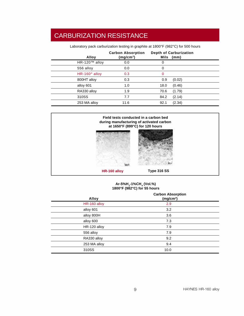
CARBURIZATION RESISTANCE
Laboratory pack carburization testing in graphite at 1800°F (982°C) for 500 hours
AlloyHR-120™ alloy
556 alloy
HR-160® alloy
800HT alloy
alloy 601
RA330 alloy
310SS
253 MA alloy
Carbon Absorption(mg/cm2)
0.0
0.0
0.3
0.3
1.0
1.9
7.7
11.6
Depth of CarburizationMils (mm)0
0
0
0.9 (0.02)
18.0 (0.46)
70.6 (1.79)
84.2 (2.14)
92.1 (2.34)
Field tests conducted in a carbon bedduring manufacturing of activated carbon
at 1650°F (899°C) for 120 hours
HR-160 alloy Type 316 SS
Ar-5%H2-1%CH4 (Vol.%)1800°F (982°C) for 55 hours
Carbon Absorption(mg/cm2)
2.9
3.2
3.6
7.3
7.9
7.9
9.2
9.4
10.0
AlloyHR-160 alloy
alloy 601
alloy 800H
alloy 600
HR-120 alloy
556 alloy
RA330 alloy
253 MA alloy
310SS
10HAYNES HR-160 alloy
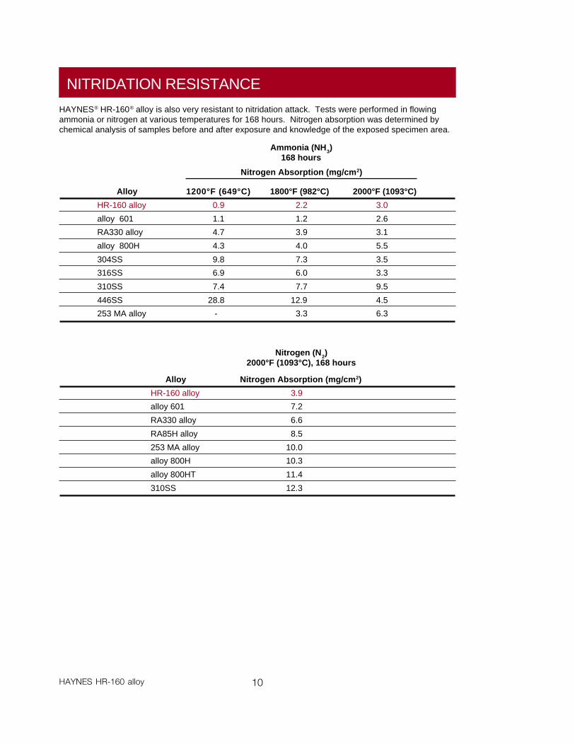
NITRIDATION RESISTANCE
HAYNES® HR-160® alloy is also very resistant to nitridation attack. Tests were performed in flowingammonia or nitrogen at various temperatures for 168 hours. Nitrogen absorption was determined bychemical analysis of samples before and after exposure and knowledge of the exposed specimen area.
Alloy
HR-160 alloy
alloy 601
RA330 alloy
alloy 800H
304SS
316SS
310SS
446SS
253 MA alloy
2000°F (1093°C)
3.0
2.6
3.1
5.5
3.5
3.3
9.5
4.5
6.3
1800°F (982°C)
2.2
1.2
3.9
4.0
7.3
6.0
7.7
12.9
3.3
1200°F (649°C)
0.9
1.1
4.7
4.3
9.8
6.9
7.4
28.8
-
Nitrogen Absorption (mg/cm2)
Alloy
HR-160 alloy
alloy 601
RA330 alloy
RA85H alloy
253 MA alloy
alloy 800H
alloy 800HT
310SS
Ammonia (NH3)168 hours
Nitrogen (N2)2000°F (1093°C), 168 hours
Nitrogen Absorption (mg/cm2)
3.9
7.2
6.6
8.5
10.0
10.3
11.4
12.3
11 HAYNES HR-160 alloy
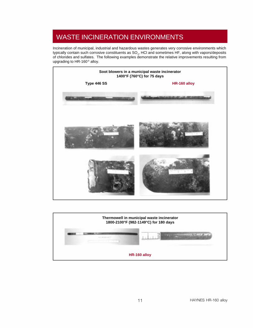
WASTE INCINERATION ENVIRONMENTS
Incineration of municipal, industrial and hazardous wastes generates very corrosive environments whichtypically contain such corrosive constituents as SO2, HCl and sometimes HF, along with vapors/depositsof chlorides and sulfates. The following examples demonstrate the relative improvements resulting fromupgrading to HR-160® alloy.
Soot blowers in a municipal waste incinerator1400°F (760°C) for 75 days
HR-160 alloyType 446 SS
Thermowell in municipal waste incinerator1800-2100°F (982-1149°C) for 180 days
HR-160 alloy
12HAYNES HR-160 alloy
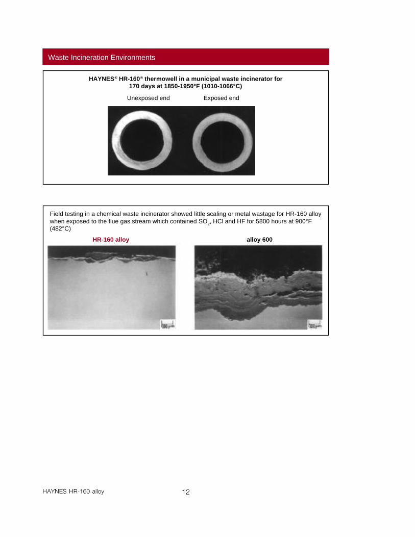
Waste Incineration Environments
HAYNES® HR-160® thermowell in a municipal waste incinerator for170 days at 1850-1950°F (1010-1066°C)
Unexposed end Exposed end
Field testing in a chemical waste incinerator showed little scaling or metal wastage for HR-160 alloywhen exposed to the flue gas stream which contained SO2, HCl and HF for 5800 hours at 900°F(482°C)
HR-160 alloy alloy 600
13 HAYNES HR-160 alloy
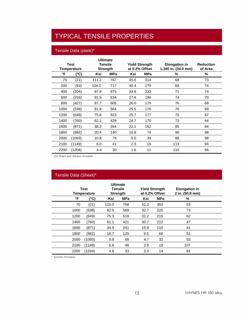
TYPICAL TENSILE PROPERTIES
TestTemperature
°F (°C)
70 (21)
200 (93)
400 (204)
600 (316)
800 (427)
1000 (538)
1200 (649)
1400 (760)
1600 (871)
1800 (982)
2000 (1093)
2100 (1149)
2200 (1204)
Reductionof Area
%
73
74
74
70
68
69
67
64
84
98
98
94
94
UltimateTensile
StrengthKsi MPa
111.2 767
104.0 717
97.9 675
91.9 634
87.7 605
81.8 564
75.8 523
62.1 428
38.3 264
20.4 140
10.8 74
6.0 41
4.4 30
Yield Strengthat 0.2% Offset
Ksi MPa
45.6 314
40.4 279
33.8 233
27.6 190
26.0 179
25.5 176
25.7 177
24.7 170
22.1 152
10.8 74
5.0 34
2.3 16
1.6 11
Elongation in1.340 in. (34.0 mm)
%
68
69
71
74
76
76
70
73
85
90
88
113
110
Tensile Data (plate)*
TestTemperature
°F (°C)
70 (21)
1000 (538)
1200 (649)
1400 (760)
1600 (871)
1800 (982)
2000 (1093)
2100 (1149)
2200 (1204)
UltimateTensile
StrengthKsi MPa
110.0 758
82.5 569
75.3 519
61.1 421
34.9 241
18.7 129
9.8 68
6.6 46
4.8 33
Yield Strengthat 0.2% Offset
Ksi MPa
51.2 353
32.7 225
31.2 215
30.7 212
15.9 110
9.5 66
4.7 32
2.8 19
2.0 14
Elongation in2 in. (50.8 mm)
%
63
73
62
47
41
51
53
107
91
Tensile Data (Sheet)*
* Hot-Rolled and Solution-Annealed
* Solution-Annealed
14HAYNES HR-160 alloy
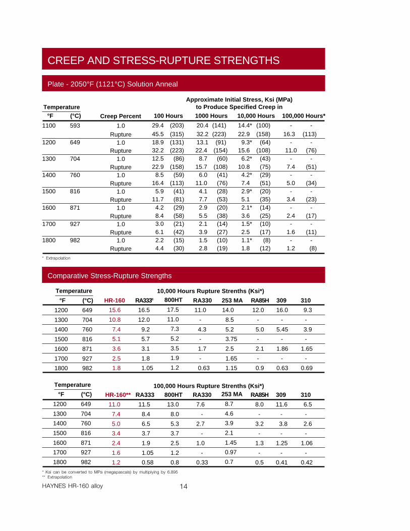
CREEP AND STRESS-RUPTURE STRENGTHS
Temperature°F (°C)
1100 593
1200 649
1300 704
1400 760
1500 816
1600 871
1700 927
1800 982
Approximate Initial Stress, Ksi (MPa)to Produce Specified Creep in
Plate - 2050°F (1121°C) Solution Anneal
Creep Percent
1.0Rupture
1.0Rupture
1.0Rupture
1.0Rupture
1.0Rupture
1.0Rupture
1.0Rupture
1.0Rupture
100,000 Hours*
- -16.3 (113)
- -11.0 (76)
- -7.4 (51)- -
5.0 (34)- -
3.4 (23)- -
2.4 (17)- -
1.6 (11)- -
1.2 (8)
10,000 Hours
14.4* (100)22.9 (158)9.3* (64)
15.6 (108)6.2* (43)
10.8 (75)4.2* (29)7.4 (51)2.9* (20)5.1 (35)2.1* (14)3.6 (25)1.5* (10)2.5 (17)1.1* (8)1.8 (12)
1000 Hours
20.4 (141)32.2 (223)13.1 (91)22.4 (154)
8.7 (60)15.7 (108)
6.0 (41)11.0 (76)
4.1 (28)7.7 (53)2.9 (20)5.5 (38)2.1 (14)3.9 (27)1.5 (10)2.8 (19)
100 Hours
29.4 (203)45.5 (315)18.9 (131)32.2 (223)12.5 (86)22.9 (158)8.5 (59)
16.4 (113)5.9 (41)
11.7 (81)4.2 (29)8.4 (58)3.0 (21)6.1 (42)2.2 (15)4.4 (30)
HR-160**
11.0
7.4
5.0
3.4
2.4
1.6
1.2
RA333
11.5
8.4
6.5
3.7
1.9
1.05
0.58
800HT
13.0
8.0
5.3
3.7
2.5
1.2
0.8
RA330
7.6
-
2.7
-
1.0
-
0.33
RA85H
8.0
-
3.2
-
1.3
-
0.5
309
11.6
-
3.8
-
1.25
-
0.41
310
6.5
-
2.6
-
1.06
-
0.42
100,000 Hours Rupture Strenths (Ksi*)253 MA
8.7
4.6
3.9
2.1
1.45
0.97
0.7
Temperature
°F (°C)
1200 649
1300 704
1400 760
1500 816
1600 871
1700 927
1800 982
* Ksi can be converted to MPa (megapascals) by multiplying by 6.895** Extrapolation
Temperature
°F (°C)
1200 649
1300 704
1400 760
1500 816
1600 871
1700 927
1800 982
800HT
17.5
11.0
7.3
5.2
3.5
1.9
1.2
Comparative Stress-Rupture Strengths
HR-160
15.6
10.8
7.4
5.1
3.6
2.5
1.8
RA333®
16.5
12.0
9.2
5.7
3.1
1.8
1.05
RA330
11.0
-
4.3
-
1.7
-
0.63
253 MA
14.0
8.5
5.2
3.75
2.5
1.65
1.15
RA85H
12.0
-
5.0
-
2.1
-
0.9
309
16.0
-
5.45
-
1.86
-
0.63
310
9.3
-
3.9
-
1.65
-
0.69
10,000 Hours Rupture Strenths (Ksi*)
* Extrapolation
15 HAYNES HR-160 alloy
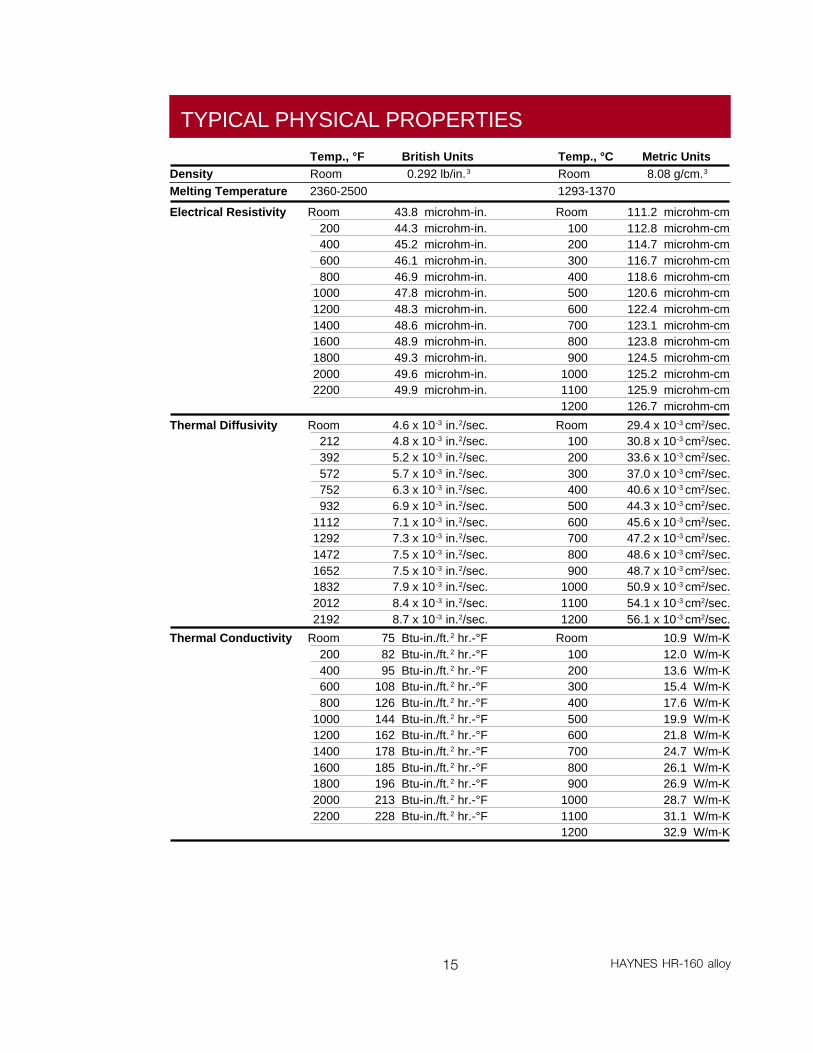
TYPICAL PHYSICAL PROPERTIES
Temp., °F British Units Temp., °C Metric UnitsDensity Room 0.292 lb/in.3 Room 8.08 g/cm.3
Melting Temperature 2360-2500 1293-1370
Electrical Resistivity Room 43.8 microhm-in. Room 111.2 microhm-cm200 44.3 microhm-in. 100 112.8 microhm-cm400 45.2 microhm-in. 200 114.7 microhm-cm600 46.1 microhm-in. 300 116.7 microhm-cm800 46.9 microhm-in. 400 118.6 microhm-cm
1000 47.8 microhm-in. 500 120.6 microhm-cm1200 48.3 microhm-in. 600 122.4 microhm-cm1400 48.6 microhm-in. 700 123.1 microhm-cm1600 48.9 microhm-in. 800 123.8 microhm-cm1800 49.3 microhm-in. 900 124.5 microhm-cm2000 49.6 microhm-in. 1000 125.2 microhm-cm2200 49.9 microhm-in. 1100 125.9 microhm-cm
1200 126.7 microhm-cm
Thermal Diffusivity Room 4.6 x 10⁻³ in.2/sec. Room 29.4 x 10⁻³ cm2/sec.212 4.8 x 10⁻³ in.2/sec. 100 30.8 x 10⁻³ cm2/sec.392 5.2 x 10⁻³ in.2/sec. 200 33.6 x 10⁻³ cm2/sec.572 5.7 x 10⁻³ in.2/sec. 300 37.0 x 10⁻³ cm2/sec.752 6.3 x 10⁻³ in.2/sec. 400 40.6 x 10⁻³ cm2/sec.932 6.9 x 10⁻³ in.2/sec. 500 44.3 x 10⁻³ cm2/sec.
1112 7.1 x 10⁻³ in.2/sec. 600 45.6 x 10⁻³ cm2/sec.1292 7.3 x 10⁻³ in.2/sec. 700 47.2 x 10⁻³ cm2/sec.1472 7.5 x 10⁻³ in.2/sec. 800 48.6 x 10⁻³ cm2/sec.1652 7.5 x 10⁻³ in.2/sec. 900 48.7 x 10⁻³ cm2/sec.1832 7.9 x 10⁻³ in.2/sec. 1000 50.9 x 10⁻³ cm2/sec.2012 8.4 x 10⁻³ in.2/sec. 1100 54.1 x 10⁻³ cm2/sec.2192 8.7 x 10⁻³ in.2/sec. 1200 56.1 x 10⁻³ cm2/sec.
Thermal Conductivity Room 75 Btu-in./ft.2 hr.-°F Room 10.9 W/m-K200 82 Btu-in./ft.2 hr.-°F 100 12.0 W/m-K400 95 Btu-in./ft.2 hr.-°F 200 13.6 W/m-K600 108 Btu-in./ft.2 hr.-°F 300 15.4 W/m-K800 126 Btu-in./ft.2 hr.-°F 400 17.6 W/m-K
1000 144 Btu-in./ft.2 hr.-°F 500 19.9 W/m-K1200 162 Btu-in./ft.2 hr.-°F 600 21.8 W/m-K1400 178 Btu-in./ft.2 hr.-°F 700 24.7 W/m-K1600 185 Btu-in./ft.2 hr.-°F 800 26.1 W/m-K1800 196 Btu-in./ft.2 hr.-°F 900 26.9 W/m-K2000 213 Btu-in./ft.2 hr.-°F 1000 28.7 W/m-K2200 228 Btu-in./ft.2 hr.-°F 1100 31.1 W/m-K
1200 32.9 W/m-K
16HAYNES HR-160 alloy
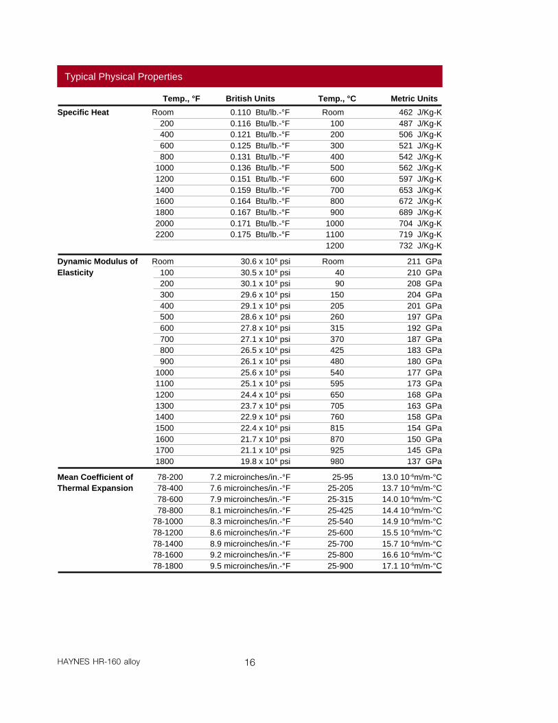
Typical Physical Properties
Specific Heat Room 0.110 Btu/lb.-°F Room 462 J/Kg-K200 0.116 Btu/lb.-°F 100 487 J/Kg-K400 0.121 Btu/lb.-°F 200 506 J/Kg-K600 0.125 Btu/lb.-°F 300 521 J/Kg-K800 0.131 Btu/lb.-°F 400 542 J/Kg-K
1000 0.136 Btu/lb.-°F 500 562 J/Kg-K1200 0.151 Btu/lb.-°F 600 597 J/Kg-K1400 0.159 Btu/lb.-°F 700 653 J/Kg-K1600 0.164 Btu/lb.-°F 800 672 J/Kg-K1800 0.167 Btu/lb.-°F 900 689 J/Kg-K2000 0.171 Btu/lb.-°F 1000 704 J/Kg-K2200 0.175 Btu/lb.-°F 1100 719 J/Kg-K
1200 732 J/Kg-K
Temp., °F British Units Temp., °C Metric Units
Dynamic Modulus of Room 30.6 x 10⁶ psi Room 211 GPaElasticity 100 30.5 x 10⁶ psi 40 210 GPa
200 30.1 x 10⁶ psi 90 208 GPa300 29.6 x 10⁶ psi 150 204 GPa400 29.1 x 10⁶ psi 205 201 GPa500 28.6 x 10⁶ psi 260 197 GPa600 27.8 x 10⁶ psi 315 192 GPa700 27.1 x 10⁶ psi 370 187 GPa800 26.5 x 10⁶ psi 425 183 GPa900 26.1 x 10⁶ psi 480 180 GPa
1000 25.6 x 10⁶ psi 540 177 GPa1100 25.1 x 10⁶ psi 595 173 GPa1200 24.4 x 10⁶ psi 650 168 GPa1300 23.7 x 10⁶ psi 705 163 GPa1400 22.9 x 10⁶ psi 760 158 GPa1500 22.4 x 10⁶ psi 815 154 GPa1600 21.7 x 10⁶ psi 870 150 GPa1700 21.1 x 10⁶ psi 925 145 GPa1800 19.8 x 10⁶ psi 980 137 GPa
Mean Coefficient of 78-200 7.2 microinches/in.-°F 25-95 13.0 10-6m/m-°CThermal Expansion 78-400 7.6 microinches/in.-°F 25-205 13.7 10-6m/m-°C
78-600 7.9 microinches/in.-°F 25-315 14.0 10-6m/m-°C78-800 8.1 microinches/in.-°F 25-425 14.4 10-6m/m-°C
78-1000 8.3 microinches/in.-°F 25-540 14.9 10-6m/m-°C78-1200 8.6 microinches/in.-°F 25-600 15.5 10-6m/m-°C78-1400 8.9 microinches/in.-°F 25-700 15.7 10-6m/m-°C78-1600 9.2 microinches/in.-°F 25-800 16.6 10-6m/m-°C78-1800 9.5 microinches/in.-°F 25-900 17.1 10-6m/m-°C
17 HAYNES HR-160 alloy
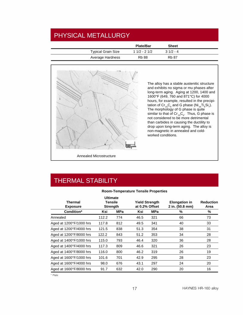
PHYSICAL METALLURGY
Plate/Bar
1 1/2 - 2 1/2
Rb 88
Sheet
3 1/2 - 4
Rb 87
Typical Grain Size
Average Hardness
The alloy has a stable austenitic structureand exhibits no sigma or mu phases afterlong-term aging. Aging at 1200, 1400 and1600°F (649, 760 and 871°C) for 4000hours, for example, resulted in the precipi-tation of Cr23C6 and G phase (Ni16Ti6Si7).The morphology of G phase is quitesimilar to that of Cr 23C6. Thus, G phase isnot considered to be more detrimentalthan carbides in causing the ductility todrop upon long-term aging. The alloy isnon-magnetic in annealed and cold-worked conditions.
Annealed Microstructure
Room-Temperature Tensile Properties
THERMAL STABILITY
ThermalExposureCondition*
Annealed
Aged at 1200°F/1000 hrs
Aged at 1200°F/4000 hrs
Aged at 1200°F/8000 hrs
Aged at 1400°F/1000 hrs
Aged at 1400°F/4000 hrs
Aged at 1400°F/8000 hrs
Aged at 1600°F/1000 hrs
Aged at 1600°F/4000 hrs
Aged at 1600°F/8000 hrs
UltimateTensile
StrengthKsi MPa
112.2 774
117.8 812
121.5 838
122.2 843
115.0 793
117.3 809
116.0 800
101.6 701
98.0 676
91.7 632
Yield Strengthat 0.2% Offset
Ksi MPa
46.5 321
49.5 341
51.3 354
51.2 353
46.4 320
46.6 321
46.2 319
42.9 295
43.1 297
42.0 290
Elongation in2 in. (50.8 mm)
%
66
40
38
34
36
26
26
28
24
20
ReductionArea
%
73
33
31
28
28
23
19
23
20
16
* Plate
18HAYNES HR-160 alloy
Room-TemperatureV-Notch Impact Strength
Condition
Annealed
Aged at 1200°F/1000 hrs
Aged at 1200°F/4000 hrs
Aged at 1200°F/8000 hrs
Aged at 1400°F/1000 hrs
Aged at 1400°F/4000 hrs
Aged at 1400°F/8000 hrs
Aged at 1600°F/1000 hrs
Aged at 1600°F/4000 hrs
Aged at 1600°F/8000 hrs
ft.-lb.
264
43
34
31
27
18
15
16
13
11
Joules
358
58
46
42
37
24
20
22
18
15
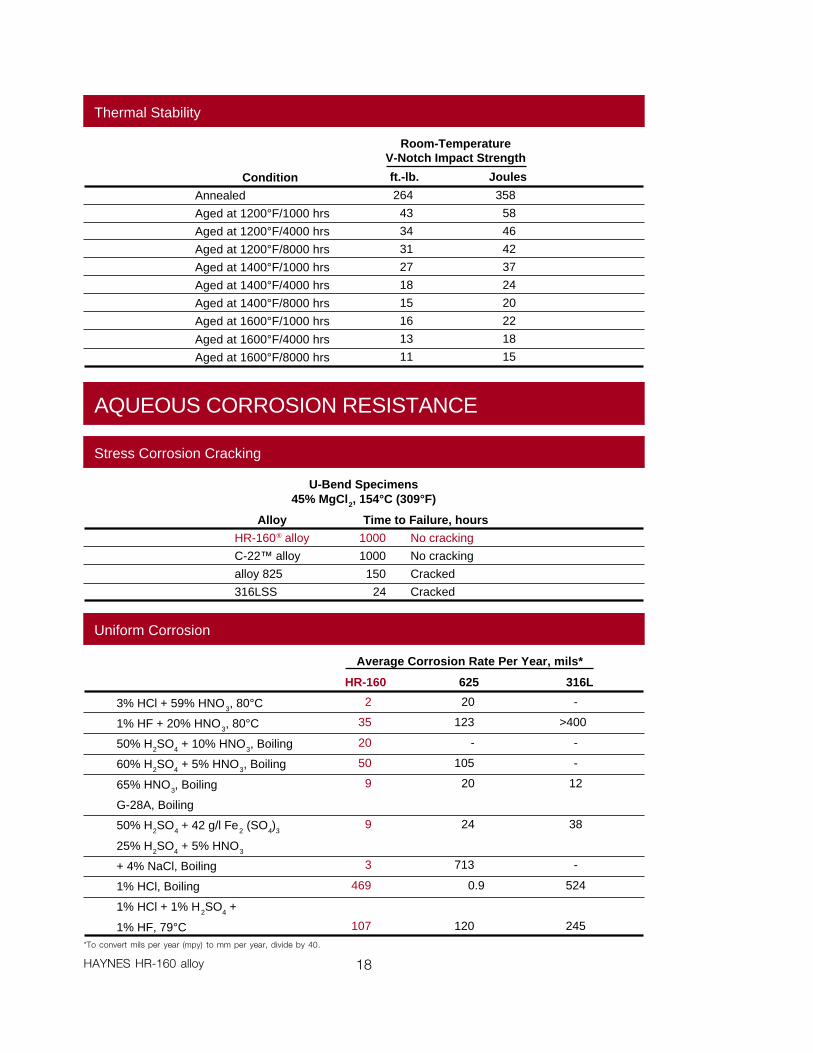
Average Corrosion Rate Per Year, mils*
3% HCl + 59% HNO3, 80°C
1% HF + 20% HNO3, 80°C
50% H2SO4 + 10% HNO3, Boiling
60% H2SO4 + 5% HNO3, Boiling
65% HNO3, Boiling
G-28A, Boiling
50% H2SO4 + 42 g/l Fe2 (SO4)3
25% H2SO4 + 5% HNO3
+ 4% NaCl, Boiling
1% HCl, Boiling
1% HCl + 1% H2SO4 +
1% HF, 79°C
625
20
123
-
105
20
24
713
0.9
120
HR-160
2
35
20
50
9
9
3
469
107
316L
-
>400
-
-
12
38
-
524
245
*To convert mils per year (mpy) to mm per year, divide by 40.
Thermal Stability
Uniform Corrosion
AQUEOUS CORROSION RESISTANCE
U-Bend Specimens45% MgCl2, 154°C (309°F)
Stress Corrosion Cracking
Alloy
HR-160® alloy
C-22™ alloy
alloy 825
316LSS
Time to Failure, hours
1000 No cracking
1000 No cracking
150 Cracked
24 Cracked

V- or U-Groove - All Thicknesses 0.125" (3.2 mm) or greater
Technique - Stringer BeadCurrent (DCEN), amperes - 120 root, 150 fillVoltage - 10 to 14Filler Metal - 0.125" (3.2 mm) diameter. HR-160 wireTravel Speed, ipm (mm/min) - 4 to 6 (100-150)Electrode Size-EWTH-2, in (mm) - 0.125 (3.2)Electrode Shape - 30° included angleCup Size - #8 or largerShielding Gas, 100% Ar CFH (l/min.) - 30 to 35Backup Gas, 100% Ar CFH (l/min.) - 10 CFHPreheat - AmbientInterpass Temperature - <200°F (93°C)
19 HAYNES HR-160 alloy
HAYNES® HR-160® alloy isreadily weldable by Gas Tung-sten Arc (TIG) and Gas MetalArc (MIG) welding processes.Many of the alloy's weldingcharacteristics are similar tothose for the HASTELLOY ®
alloys and the same precau-tions apply. Submerged arcwelding is not recommended asthis process is characterized byhigh heat input which couldresult in distortion and hotcracking. HR-160 filler metal isprone to start/stop cracking.The filler metal may be prone tohot cracking when weldingheavy plate (e.g. greater than1/2 inch thick) under highlyrestrained conditions. Anylocalized cracking should beremoved by grinding prior tofurther welding. Do not attemptto remelt or "wash-out" weldingcracks.
Base Metal PreparationThe joint surface and adjacentarea should be thoroughlycleaned before welding. Allgrease, oil, crayon marks, sulfurcompounds and other foreignmatter should be removed. It ispreferable, but not mandatory,that the alloy be in the solution-annealed condition whenwelded.
Filler Metal SelectionMatching composition fillermetal is recommended forjoining HR-160 alloy. Whendissimilar base metals are to bejointed, such as HR-160 alloy toa stainless steel, HAYNES 556filler metal is recommended.
Preheating, InterpassTemperatures and Post-Weld Heat TreatmentPreheat should not be used solong as the base metal to
be welded is above 32°F (0°C).Interpass temperatures shouldbe less than 200°F (93°C).Auxiliary cooling methods maybe used between weld passes,as needed, providing that suchmethods do not introducecontaminants. Post-weld heattreatment is not normallyrequired for HR-160 alloy.
Nominal WeldingParametersNominal welding parametersare provided as a guide forperforming typical operations.These are based on weldingconditions used in our labora-tory and should be consideredonly as a guideline. For furtherinformation, please consultHaynes publication H-3159.
Manual Gas Tungsten Arc Welding
WELDING
20HAYNES HR-160 alloy
Short Circuiting Transfer ModeAll Thicknesses 0.125" (3.2 mm) or greater
Technique - Stringer or slight weaveCurrent (DCEN), amperes - 100 to 140Voltage - 18 to 21Wire Feed Rate, ipm (m/min) - 170 to 190 (4.3 to 4.8)Stickout, in (mm) - 0.5 to 0.75 (12.7 to 19)Filler Metal - 0.045" (1.1 mm) diameter HR-160 wireTravel Speed, ipm (mm/min - 8 to 14 (203 to 356)Shielding Gas Flow, CFH (l/min.) - 50 (23.7)Gas - Argon - 25% Helium
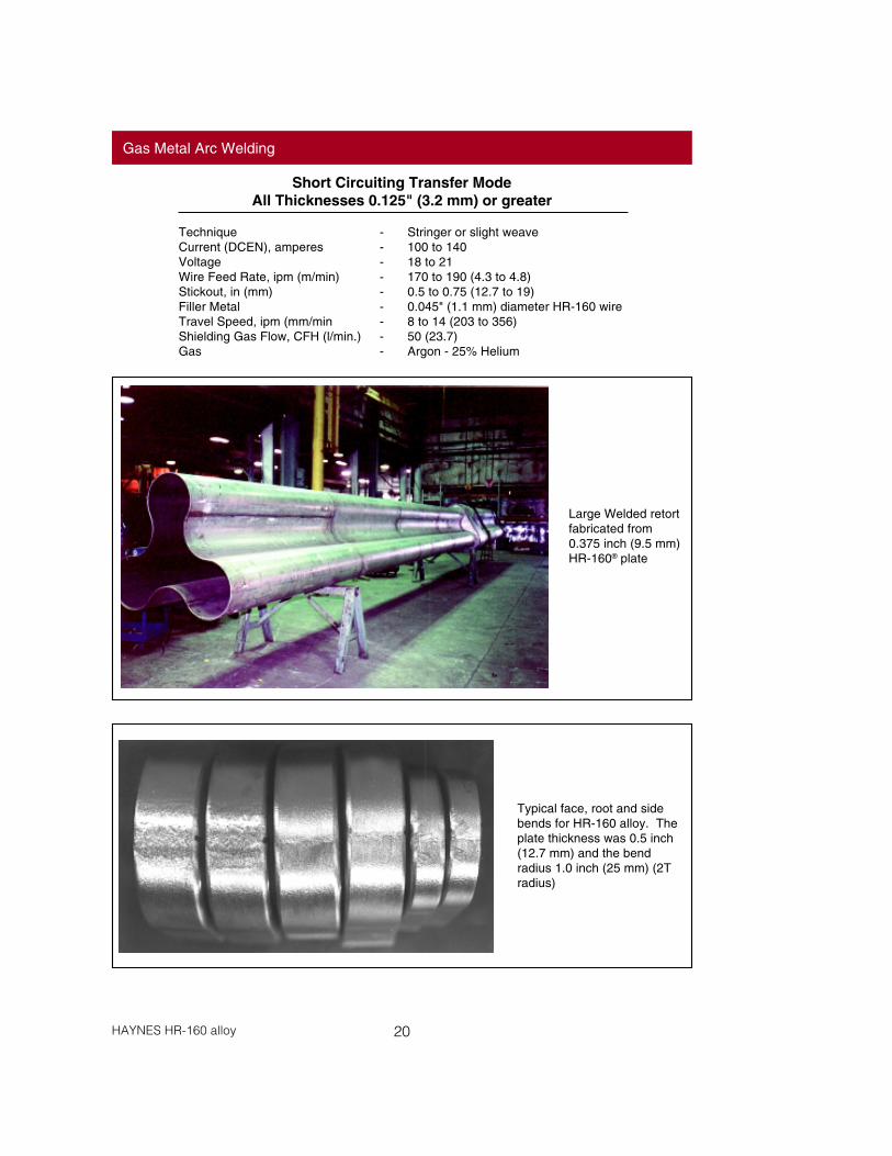
Gas Metal Arc Welding
Large Welded retortfabricated from0.375 inch (9.5 mm)HR-160® plate
Typical face, root and sidebends for HR-160 alloy. Theplate thickness was 0.5 inch(12.7 mm) and the bendradius 1.0 inch (25 mm) (2Tradius)
21 HAYNES HR-160 alloy
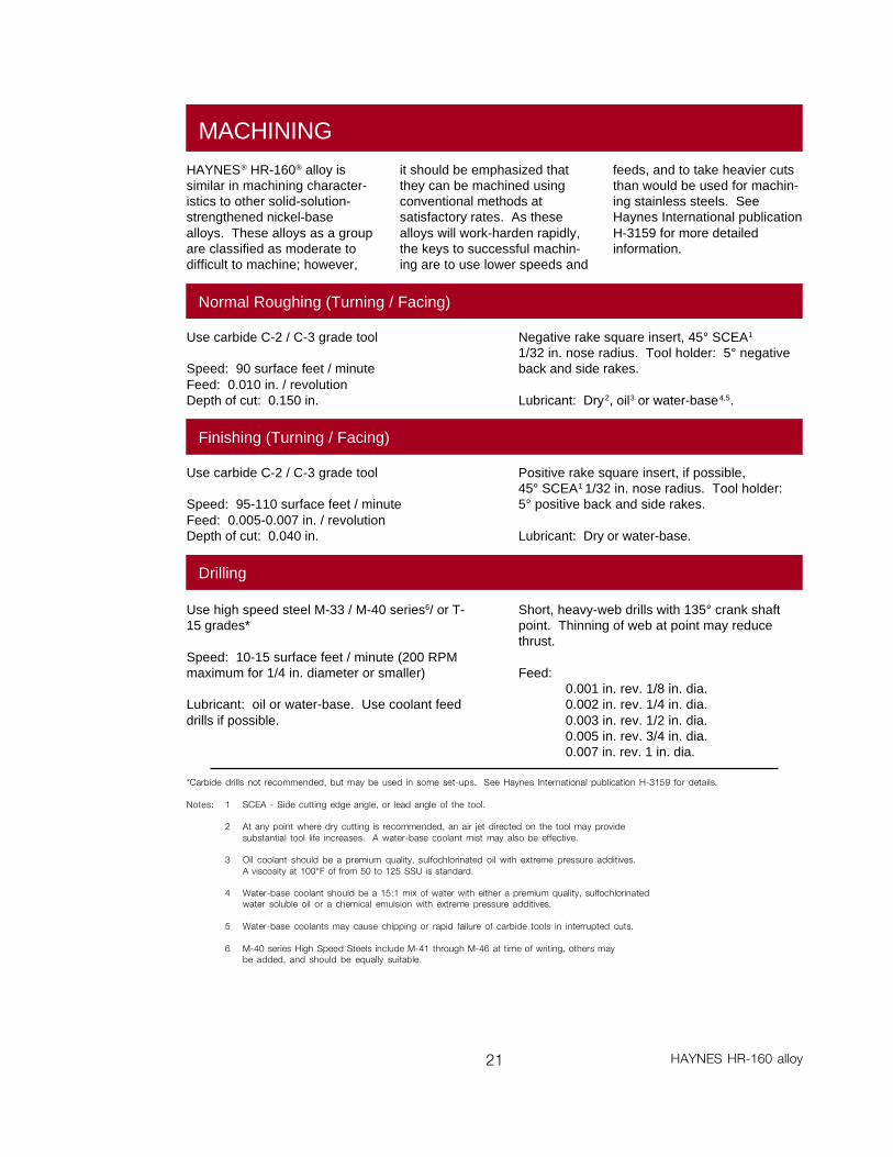
HAYNES® HR-160® alloy issimilar in machining character-istics to other solid-solution-strengthened nickel-basealloys. These alloys as a groupare classified as moderate todifficult to machine; however,
it should be emphasized thatthey can be machined usingconventional methods atsatisfactory rates. As thesealloys will work-harden rapidly,the keys to successful machin-ing are to use lower speeds and
feeds, and to take heavier cutsthan would be used for machin-ing stainless steels. SeeHaynes International publicationH-3159 for more detailedinformation.
Normal Roughing (Turning / Facing)
Use carbide C-2 / C-3 grade tool
Speed: 90 surface feet / minuteFeed: 0.010 in. / revolutionDepth of cut: 0.150 in.
Negative rake square insert, 45° SCEA1
1/32 in. nose radius. Tool holder: 5° negativeback and side rakes.
Lubricant: Dry2, oil3 or water-base4,5.
Finishing (Turning / Facing)
Use carbide C-2 / C-3 grade tool
Speed: 95-110 surface feet / minuteFeed: 0.005-0.007 in. / revolutionDepth of cut: 0.040 in.
Positive rake square insert, if possible,45° SCEA1 1/32 in. nose radius. Tool holder:5° positive back and side rakes.
Lubricant: Dry or water-base.
Drilling
Use high speed steel M-33 / M-40 series6/ or T-15 grades*
Speed: 10-15 surface feet / minute (200 RPMmaximum for 1/4 in. diameter or smaller)
Lubricant: oil or water-base. Use coolant feeddrills if possible.
Short, heavy-web drills with 135° crank shaftpoint. Thinning of web at point may reducethrust.
Feed:0.001 in. rev. 1/8 in. dia.0.002 in. rev. 1/4 in. dia.0.003 in. rev. 1/2 in. dia.0.005 in. rev. 3/4 in. dia.0.007 in. rev. 1 in. dia.
*Carbide drills not recommended, but may be used in some set-ups. See Haynes International publication H-3159 for details.
Notes: 1 SCEA - Side cutting edge angle, or lead angle of the tool.
2 At any point where dry cutting is recommended, an air jet directed on the tool may providesubstantial tool life increases. A water-base coolant mist may also be effective.
3 Oil coolant should be a premium quality, sulfochlorinated oil with extreme pressure additives.A viscosity at 100°F of from 50 to 125 SSU is standard.
4 Water-base coolant should be a 15:1 mix of water with either a premium quality, sulfochlorinatedwater soluble oil or a chemical emulsion with extreme pressure additives.
5 Water-base coolants may cause chipping or rapid failure of carbide tools in interrupted cuts.
6 M-40 series High Speed Steels include M-41 through M-46 at time of writing, others maybe added, and should be equally suitable.
MACHINING
22HAYNES HR-160 alloy
HEALTH AND SAFETY
Acknowledgements
20CB-3 is a trademark of Carpenter Technology Corporation.253 MA is a trademark of Avesta Jernverks Aktiebolag.800HT is a trademark of Inco Family of Companies.RA85H, RA330 and RA333 are trademarks of Rolled Alloys, Inc.
Those involved with the weldingindustry are obligated to providesafe working conditions and beaware of the potential hazardsassociated with welding fumes,gases, radiation, electricalshock, heat, eye injuries, burns,etc. Various local, municipal,state and federal regulations(OSHA, for example) relative tothe welding and cutting pro-cesses must be considered.
The operation and maintenanceof welding and cutting equip-ment should conform to theprovisions of American NationalStandard ANSI Z49.1-88,"Safety in Welding and Cutting".Attention is especially called toSection 4 (Protection of Person-nel), Section 5 (Ventilation) andSection 7 (Confined Spaces) ofthat document. Adequateventilation is required during allwelding and cutting operations.Specific requirements are
shown in the Material SafetyData Sheet, and the productlabel. Use industrial hygiene airmonitoring to ensure compli-ance with the recommendedexposure limits. ALWAYS USEEXHAUST VENTILATION.
RESPIRATORY PROTECTION:Be sure to use a fume respira-tor or air supplied respiratorwhen welding in confinedspaces or where local exhaustor ventilation does not keepexposures below the PEL andTLV limits.
WARNING: Protect yourselfand others. Be sure the label isread and understood by thewelder. FUMES and GASEScan be dangerous to yourhealth. Overexposure to fumesand gases can result in LUNGDAMAGE. ARC RAYS caninjure eyes and burn skin.ELECTRIC SHOCK can kill.
included in Section 5 for naturalventilation versus mechanicalventilation methods. Whenwelding in confined spaces,ventilation shall also be suffi-cient to assure adequateoxygen for life support.
The following precautionarywarning is supplied with allwelding products. It should beprovided to and fully understoodby all employees involved withwelding.
CAUTION: "Welding mayproduce fumes and gaseshazardous to health. Avoidbreathing these fumes andgases. Use adequate ventila-tion. See ANSI/AWS Z49.1-88,"Safety in Welding and Cutting"published by the AmericanWelding Society.
EXPOSURES: Maintain allexposures below the limits

23 HAYNES HR-160 alloy
Cross-section of HR-160 ® flue-gas stackannubar flow monitoring device for wasteincineration and chemical process indus-tries.
Lining (inner cylinder) of exhaust ducting in pulpand paper recovery boiler made from HR-160alloy. Outer shell is carbon steel.
Many waste incineration and chemical processfacilities have used HR-160 thermocouple protec-tion tubes with outstanding success. Life exten-sions greater than 10X compared to Ni-Cr alloysand stainless steels are common.
HR-160 tube shields are considered the premiersuperheater tube shield material for municipal andindustrial waste incineration systems. The use ofHR-160 alloy has resulted in greatly improved lifein municipal waste incinerators where hightemperature corrosion and fly ash erosion aremajor considerations.
APPLICATIONS
HASTELLOY® Family of Corrosion-Resistant Alloys
Standard Forms:Bar, Billet, Remelt Materials, Plate, Sheet, Strip, Coils, Seamless or Welded Pipe & Tubing,Welding Wire and Coated Electrodes
Properties Data:The data and information in this publication are basedon work conducted principally by Haynes International, Inc.and occasionally supplemented by information from theopen literature, and are believed to be reliable. However,we do not make any warranty or assume any legal liabilityor responsibility for its accuracy, completeness or useful-ness, nor do we represent that its use would not infringeupon private rights. Any suggestions as to uses and
applications for specific alloys are opinions only andHaynes International, Inc. makes no warranty of resultsto be obtained in any particular situation. For specificconcentrations of elements present in a particularproduct and a discussion of the potential health effectsthereof, refer to the Material Safety Data Sheet suppliedby Haynes International, Inc.
For More Information Contact:
HASTELLOY Family of Heat-Resistant Alloys
(All trademarks are owned by Haynes International, Inc. except FERRALIUM which is a trademark of Langley Alloys, LTD.)
STANDARD PRODUCTS By Brand or Alloy Designation:
B-2, B-3™, C-4, C-22™, C-276, D-205™, G-3, G-30®, G-50®, H-9M™ and N
S, W, and X
25, 31, R-41, 75, HR-120™, 150, 188, 214™, 230™, 230-W™, 242™, 263, 625, 718, X-750, MULTIMET® andWASPALOY
ULTIMET®
HAYNES Family of High-Temperature-Corrosion-Resistant Alloys
Corrosion-Wear Resistant Alloy
Super Stainless Steel HAYNES Titanium Alloy Tubular
Wear-Resistant Alloy
HR-160® and 556™
6B
Ti-3Al-2.5VFERRALIUM® 255
For Referral to Authorized Distributors in your area Fax: 1-317-456-6905
Printed in U.S.A. 090993
HAYNES® Family of Heat-Resistant Alloys
ItalyHaynes International, S.R.L.Viale Brianza, 820127 MilanoTel: 39-2-2614-1331Telex: 3505-87-MZMIFAX: 39-2-282-8273
SwitzerlandNickel Contor, AGGotthardstrasse 21CH-8022 ZurichTel: 41-1-201-7322Telex: 815-601FAX: 41-1-201-7333
Windsor, Connecticut 06095430 Hayden Station RoadTel: 203-688-7771 800-426-1963FAX: 203-688-5550
Houston, Texas 77041The Northwood Industrial Park12241 FM 529Tel: 713-937-7597 800-231-4548Telex: 225465FAX: 713-937-4596
EnglandHaynes International, Ltd.P.O. Box 10Parkhouse StreetOpenshawManchester, M11 2ERTel: 44-61-230-7777Telex: 667611FAX: 44-61-223-2412
FranceHaynes International, S.A.R.L.Boite Postale 711095054 CERGY PONTOISECedexTel: 33-1-34-48-3100Telex: 605373FAX: 33-1-30-37-8022
Kokomo, Indiana 46904-90131020 W. Park AvenueP.O. Box 9013Tel: 317-456-6012 800-354-0806Telex: 272280FAX: 317-456-6905
Anaheim, California 92806Stadium Plaza1520 South Sinclair StreetTel: 714-978-1775 800-531-0285TWX: 910 591 1884FAX: 714-978-1743
Arcadia, Louisiana 71001-9701Highway 80 WestRoute 1 Box 8Tel: 318-263-9571 800-648-8823Telex: 588427FAX: 318-263-8088