Embed Size (px)
Citation preview

H55MXV Series Motherboard
User’s Manual

Statement:This manual is the intellectual property of Foxconn, Inc. Although the information in this manual may be changed or modified at any time, Foxconn does not obligate itself to inform the user of these changes.
Trademark:All trademarks are the property of their respective owners.
Version:User’s Manual V1.0 for H55MXV Series motherboard.P/N: 3A2220C00-000-G
Symbol description:
Caution: refers to important information that can help you to use motherboard better, and tells you how to avoid problems.
Warning: indicating a potential risk of hardware damage or physical injury may exist.
WEEE: The use of this symbol indicates that this product may not be treated as household waste. By ensuring this product is disposed of correctly, you will help prevent potential negative consequences for the environment and human health, which could other-wise be caused by inappropriate waste handling of this product. For more detailed information about recycling of this product, please contact your local city office, your household waste disposal service or the shop where you purchased this product.
More information:If you want more information about our products, please visit Foxconn’s
website: http://www.foxconnchannel.com
CAUT
ION
!WARNING!
© All rights reserved.All trade names are registered trademarks of respective manufacturers listed.
All images are for reference only, please refer to the physical motherboard for specific features.

Declaration of conformity
HON HAI PRECISION INDUSTRY COMPANY LTD66 , CHUNG SHAN RD., TU-CHENG INDUSTRIAL DISTRICT,
TAIPEI HSIEN, TAIWAN, R.O.C.
declares that the productMotherboard H55MXV
is in conformity with(reference to the specification under which conformity is declared in
accordance with 89/336 EEC-EMC Directive)
■ EN 55022: 1998/A2: 2003 Limits and methods of measurements of radio disturbance characteristics of information technology equipment
■ EN 61000-3-2/:2000 Electromagnetic compatibility (EMC) Part 3: Limits Section 2: Limits for harmonic current emissions (equipment input current <= 16A per phase)■ EN 61000-3-3/A1:2001 Electromagnetic compatibility (EMC) Part 3: Limits Section 2: Limits of voltage fluctuations and flicker in low
voltage supply systems for equipment with rated current <= 16A
■ EN 55024/A2:2003 Information technology equipment-Immunity characteristics limits and methods of measurement
Signature : Place / Date : TAIPEI/2009
Printed Name : James Liang

Declaration of conformity
Trade Name: FOXCONN Model Name: H55MXV Responsible Party: PCE Industry Inc. Address: 458 E. Lambert Rd. Fullerton, CA 92835 Telephone: 714-738-8868 Facsimile: 714-738-8838
Equipment Classification: FCC Class B Subassembly Type of Product: Motherboard Manufacturer: HON HAI PRECISION INDUSTRY COMPANY LTD Address: 66 , CHUNG SHAN RD., TU-CHENG INDUSTRIAL DISTRICT, TAIPEI HSIEN, TAIWAN, R.O.C.
Supplementary Information:
This device complies with Part 15 of the FCC Rules. Operation is subject to the following two conditions : (1) this device may not cause harmful interference, and (2) this device must accept any interference received, including interference that may cause undesired operation.Tested to comply with FCC standards.
Signature : Date : 2009

Installation Precautions
Please carefully read the following procedures to install your computer :■ It is suggested to select high-quality, certified fans in order to avoid damage
to the motherboard and CPU due to high temperature. Never turn on the computer if the CPU fan is not properly installed.
■ We cannot guarantee that your system can operate normally when your CPU is overclocked. Normal operation depends on the overclocking capac-ity of your device.
■ If there is any, when connecting USB, audio, 1394a, RS232 COM, IrDA or S/PDIF cables to the internal connectors on the motherboard, make sure their pinouts are matching with the connectors on the motherboard. Incorrect connections might damage the motherboard.
■ When handling the motherboard, avoid touching any metal leads or connec-tors.
■ If there is a PCI Express x16 graphics card installed in your system, we recommend using a 24-pin ATX power supply to get the best performance.
■ Before turning on the power, please make sure the power supply AC input voltage setting has been configured to the local standard.
■ To prevent damage to the motherboard, do not allow screws to come in contact with the motherboard circuit or its components. Also, make sure there are no leftover screws or metal components placed on the motherboard or within the computer casing.
■ If you are uncertain about any installation steps or have a problem related to the use of the product, please consult a certified computer technician.
CAUT
ION
!
■ Electrostatic discharge (ESD) is the sudden and momentary electric current that flows between two objects at different electrical potentials. Normally it comes out as a spark which will quickly damage your electronic equipment. Please wear an electrostatic discharge (ESD) wrist strap when handling components such as a motherboard, CPU or memory.
■ Ensure that the DC power supply is turned off before installing or removing CPU, memory, expansion cards or other peripherals. It is recommended to unplug the AC power cord from the power supply outlet. Failure to unplug the power supply cord may result in serious damage to your system.
WARNING!

TAble of CoNTeNTS
Chapter 1 Product Introduction Product Specifications ..............................................................................2 Layout.......................................................................................................4 Back Panel Connectors ............................................................................5Chapter 2 Hardware Install Install the CPU and CPU Cooler ..............................................................8 Install the Memory ..................................................................................11 Install an Expansion Card ......................................................................13 Install other Internal Connectors ............................................................14 Jumpers ..................................................................................................18Chapter 3 bIoS Setup Enter BIOS Setup ...................................................................................21 Main Menu..............................................................................................21 System Information ................................................................................23 Advanced BIOS Features.......................................................................25 Fox Central Control Unit .........................................................................27 Advanced Chipset Features ...................................................................31 Integrated Peripherals ............................................................................32 Power Management Setup .....................................................................36 PC Health Status ....................................................................................38 BIOS Security Features..........................................................................39 Load Optimal Defaults ............................................................................40 Save Changes and Exit ..........................................................................40 Discard Changes and Exit ......................................................................40Chapter 4 CD Instruction Utility CD content....................................................................................42 Install driver and utility ............................................................................43 FOX ONE Main Page ........................................................................................45 CPU Control .....................................................................................49 Frequency Control ............................................................................51 Limit Setting......................................................................................52 Voltage Control .................................................................................54 Fan Control.......................................................................................55 FOX LiveUpdate Local Update ....................................................................................56

Online Update ..................................................................................58 Configure .........................................................................................61 About & Help ....................................................................................63 FOX LOGO .............................................................................................64 FOX DMI ................................................................................................65
Technical Support :
Website :http://www.foxconnchannel.com
Support Website :http://www.foxconnsupport.com
Worldwide online contact Support :http://www.foxconnsupport.com/inquiry.aspx
CPU Support list :http://www.foxconnsupport.com/cpusupportlist.aspx
Memory, VGA Compatibility list :http://www.foxconnsupport.com/complist.aspx
Support

Thank you for buying Foxconn H55MXV Series motherboard. Foxconn products are engineered to maximize computing power, providing only what you need for break-through performance.
With advanced overclocking capability and a range of connectivity features for today multi-media computing requirements, H55MXV enables you to unleash more power from your computer.
This chapter includes the following information:■ Product Specifications■ Layout■ Back Panel Connectors

1
2
1-1 Product Specifications
CPU Support LGA 1156 socket Intel® CPU: Intel® CoreTM i7, CoreTM i5 and CoreTM i3 processorsDMI Bus Full duplex up to 10Gb/s each directionChipset Intel® H55 Memory 2 x 240-pin DDR3 DIMM sockets Support up to 8GB of system memory Dual channel DDR3 1333/1066MHz architecture Audio Realtek 6-channel audio chip High Definition Audio 2/4/5.1-channel Support for S/PDIF out Support Jack-Sensing functionLAN Realtek 10/100/1000Mb/s LAN chipExpansion Slots 1 x PCI Express x16 slots 1 x PCI Express x1 slots 2 x PCI slotOnboard Serial ATA 6 x SATA connectors 300MB/s data transfer rate Support hot plug and NCQ (Native Command Queuing)USB Support hot plug Supports up to 12 x USB 2.0 ports (6 rear panel ports, 3 onboard USB head-
ers supporting 6 extra ports) Support USB 2.0 protocol up to 480Mb/sInternal Connectors 1 x 24-pin ATX main power connector 1 x 4-pin ATX 12V power connector 1 x CPU fan header (4-pin) 1 x System fan headers (4-pin) 1 x Front Audio connector 1 x SPDIF-OUT connector 1 x Speaker connector 3 x USB 2.0 connectors (supporting 6 x USB devices) 1 x Front Panel connector 6 x SATA connectors 1 x TPM connector 1 x COM connector 1 x INTR connector 1 x CIR connectorBack Panel 1 x PS/2 portConnectors 1 x Parallel port 6 x USB 2.0 ports 1 x DVI-D port 1 x VGA port 1 x RJ-45 LAN port

1
3
6-channel Audio Ports Hardware Monitor System voltage detection CPU/System temperature detection CPU/System fan speed detection CPU/System overheating shutdown CPU/System fan speed controlPCI Express x1 Support 250MB/s (500MB/s concurrent) bandwidth Low power consumption and power management featuresPCI Express x16 Gen2.0 Support 8GB/s (16GB/s concurrent) bandwidth Low power consumption and power management featuresGreen Function Support ACPI (Advanced Configuration and Power Interface) Support S0 (normal), S1 (power on suspend), S3 (suspend to RAM), S4
(suspend to disk), and S5 (soft - off)Bundled Software FOX ONE FOX LiveUpdate FOX LOGO FOX DMIOperating System Support for Microsoft® Windows® Vista/XP/7Form Factor Micro ATX Form Factor, 9.6 inches x 8.6 inches (24.4cm x 21.8cm)
1
4
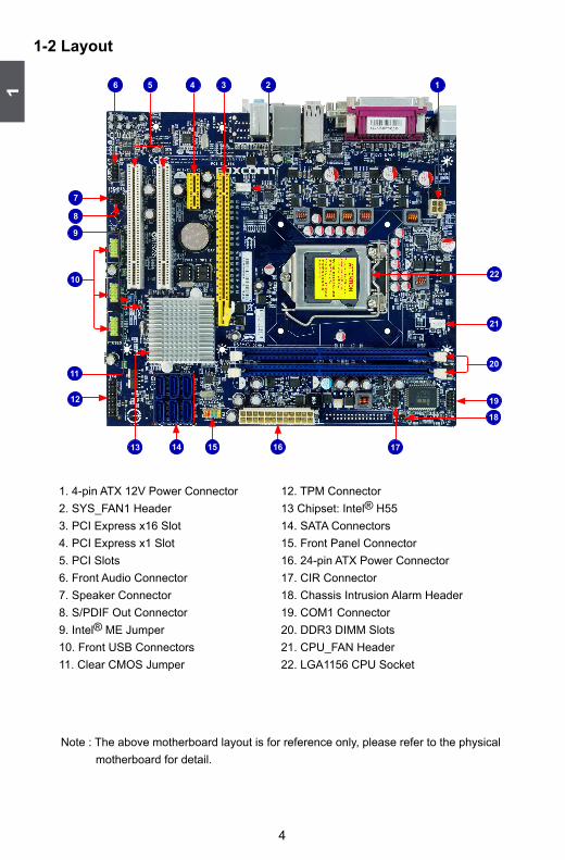
1-2 layout
Note : The above motherboard layout is for reference only, please refer to the physical motherboard for detail.
1. 4-pin ATX 12V Power Connector2. SYS_FAN1 Header3. PCI Express x16 Slot 4. PCI Express x1 Slot5. PCI Slots 6. Front Audio Connector7. Speaker Connector8. S/PDIF Out Connector 9. Intel® ME Jumper10. Front USB Connectors11. Clear CMOS Jumper
12. TPM Connector 13 Chipset: Intel® H55 14. SATA Connectors15. Front Panel Connector16. 24-pin ATX Power Connector17. CIR Connector18. Chassis Intrusion Alarm Header19. COM1 Connector20. DDR3 DIMM Slots 21. CPU_FAN Header22. LGA1156 CPU Socket
1
15
7
36 24
16
5
12
1413 17
19
9
10
11
18
20
21
8
22

1
5
1-3 back Panel Connectors
1. PS/2 Mouse PortUse the upper port (green) to connect a PS/2 mouse.
2. PS/2 Keyboard PortUse the lower port (purple) to connect a PS/2 keyboard.
3. Parallel PortThis connector provides printer port interface.
4. VGA PortTo connect with external display devices, such as monitor or LCD display.
5. DVI-D PortThe DVI-D port supports DVI-D specification. Connect a monitor that supports DVI-D connec-tion to this port.
6. USb PortsThe USB port supports the USB 2.0/1.1 specification. Use this port for USB devices such as an USB keyboard/mouse, USB printer, USB flash drive and etc.
7. Audio PortsFor the definition of each audio port, please refer to the table below :
* : Please refer to Chapter 4, and install the Realtek audio driver (in CD) to assign the audio output ports for different applications of 2/4/5.1 channels. The fundamental audio outputs are depicted in the table above.
USB Ports
LAN PortParallel Port
PS/2 Keyboard Port
PS/2 Mouse Port
7
1 3
Audio Ports
8
VGA Port4 52 6
Line Out
Microphone
Line In
DVI-D Port
Port 2-channel 4-channel 5.1-channel
Blue Line In Rear Speaker Out* Rear Speaker Out*
Green Line Out Front Speaker Out Front Speaker Out
Pink Microphone In Microphone In Center/Subwoofer Out*

1
6
8. RJ-45 lAN PortThe Ethernet LAN port provides Internet connection at up to 10/100/1000Mb/s data rate.
LAN TypeLeft: Active Right: Link
Status Description Status Description
1000M
Off No Link Off No Link
Green Blinking
Data Activity
Off 10Mb/s Connection
Green 100Mb/s Connection
Orange 1000Mb/s Connection
LinkLED
Active LED

This chapter introduces the hardware installation process, including the installation of the CPU, memory, power supply, slots, pin headers and the mounting of jumpers. Caution should be exercised during the installation of these modules. Please refer to the motherboard layout prior to any installation and read the contents in this chapter carefully.
This chapter includes the following information :■ Install the CPU and CPU Cooler■ Install the Memory■ Install an Expansion Card■ Install other Internal Connectors■ Jumpers
Please visit the following website for more supporting information about your motherboard.CPU Support list:http://www.foxconnsupport.com/cpusupportlist.aspxMemory, VGA Compatibility list:http://www.foxconnsupport.com/complist.aspx

8
2
8
2-1 Install the CPU and CPU Cooler
Install the CPULocate the alignment keys on the motherboard CPU socket and the notches on the CPU.
Read the following guidelines before you begin to install the CPU :■ Make sure that the motherboard supports the CPU.■ Always turn off the computer and unplug the power cord from the power supply before
installing the CPU to prevent hardware damage.■ Locate the pin one of the CPU. The CPU cannot be inserted if oriented incorrectly. (Or
you may locate the notches on both sides of the CPU and alignment keys on the CPU socket.)
■ Apply an even and thin layer of thermal grease on the surface of the CPU.■ Do not turn on the computer if the CPU cooler is not installed, otherwise overheating
and damage of the CPU may occur.■ Set the CPU host frequency in accordance with the CPU specifications. It is not
recommended that the system bus frequency be set beyond hardware specifications since it does not meet the standard requirements for the peripherals. If you wish to set the frequency beyond the standard specifications, please do so according to your hardware specifications including the CPU, graphics card, memory, hard drive, etc.
Hyper-Threading Technology System Requirements: (Go to Intel's website for more information about the Hyper-Threading Technology)■ An Intel® CPU that supports HT Technology■ A chipset that supports HT Technology■ An operating system that is optimized for HT Technology■ A BIOS that supports HT Technology and has it enabled
CAU
TIO
N
!
LGA1156 CPU Socket
Alignment Key
Pin-1 corner of the CPU Socket
LGA1156 CPU
Notch
Pin-1 triangle marking of CPU
9
2
9
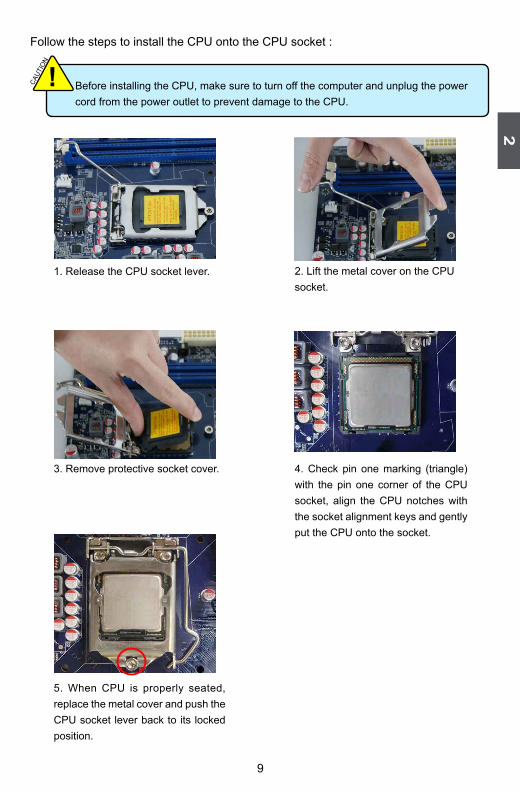
Follow the steps to install the CPU onto the CPU socket :
2. Lift the metal cover on the CPU socket.
3. Remove protective socket cover.
5. When CPU is properly seated, replace the metal cover and push the CPU socket lever back to its locked position.
4. Check pin one marking (triangle) with the pin one corner of the CPU socket, align the CPU notches with the socket alignment keys and gently put the CPU onto the socket.
Before installing the CPU, make sure to turn off the computer and unplug the power cord from the power outlet to prevent damage to the CPU.
CAUT
ION
!
1. Release the CPU socket lever.

10
2
10
Install the CPU CoolerFollow the steps below to correctly install the CPU cooler on the motherboard.
1. Apply and spread an even thermal grease on the surface of CPU.
2. Place the four bolts of the CPU cooler to the holes of the motherboard, push them straight down from the top, and the bolts will be fastened on the motherboard. That's it.
3. Check the solder side of the motherboard, the push pin should be fixed as depicted in the picture.
32
1
4. Attach the 4-wire CPU cooler connector to the CPU FAN header on the motherboard .
Release bolts of CPU cooler from motherboard :1.Turning the push pin (bol t)
along with the direction of arrow (counterclockwise).
2. Pull the push pin straight up.3. Turning push pin clockwise to its
default position.
Use extreme care when removing the CPU cooler because the thermal grease may adhere to the CPU. Inadequately removing the CPU cooler may damage the CPU.
CAU
TIO
N
!

11
2
11
2-2 Install the Memory
Dual Channel Memory Configuration
This motherboard provides two DDR3 memory sockets and supports Dual Channel Technology. When memory is installed, the BIOS will automatically check the memory in your system.
Two DDR3 memory sockets are divided into two channels: Channel 0 : DIMM1 Channel 1 : DIMM2 The combinations of DIMM modules are :
Read the following guidelines before you begin to install the memory :■ Make sure that the motherboard supports the memory. It is recommended that memory
of the same capacity, brand, speed, and chips be used.■ Always turn off the computer and unplug the power cord from the power outlet before
installing the memory to prevent hardware damage.■ Memory modules have a foolproof design. A memory module can be installed in only
one direction. If you are unable to insert the memory, switch the direction.
CAU
TIO
N
!
It is recommended that memory of the same capacity, brand, speed, and chips be used and please select dual channel first to achieve optimum performance.
CAU
TIO
N
!
DIMM1 DIMM2
Single Channel DS/SS -
Single Channel - DS/SS
Dual Channel DS/SS DS/SS(DS : Double Side, SS : Single Side, - : No Memory)

12
2
12
Installing a Memory
If you take a look at front side of memory module, it has asymmetric pin counts on both sides separated by a notch in the middle, so it can only fit in one direction. Follow the steps below to correctly install your memory modules into the sockets.
Step 1:Spread the clips at both ends of the memory socket. Place the memory module onto the socket, then put your fingers on top edge of the module, and push it down firmly and seat it vertically into the memory socket.
Step 2:The clips at both ends of the socket will snap into place when the memory module is securely inserted.
Notch
■ Before installing a memory module, make sure to turn off the computer and unplug the power cord from the power outlet to prevent damage to the memory module. Be sure to install DDR3 DIMMs on this motherboard.
CAUT
ION
!
96-P
in14
4-P
in

13
2
13
2-3 Install an expansion Card
follow the steps below to correctly install your expansion card in the expansion slot.1. Locate an expansion slot that supports your card. Remove the metal slot cover from the chassis
back panel.2. Align the card with the slot, and press down on the card until it is fully seated in the slot.3. Make sure the metal contacts on the card are completely inserted into the slot.4. Secure the card's metal bracket to the chassis back panel with a screw.5. After installing all expansion cards, replace the chassis cover.6. Turn on your computer. If necessary, go to BIOS Setup to make any required BIOS changes for
your expansion card(s).7. Install the driver provided with the expansion card in your operating system.
Installing and Removing a PCI Express x16 Graphics Card :
• Installing a Graphics Card:Gently insert the graphics card into the PCI Express x16 slot. Make sure the graphics card is locked by the latch at the end of the PCI Express x16 slot.
• Removing the Card:Push the latch at the end of the PCI Express x16 slot to release the card and then pull the card straight up from the slot.
■ Make sure the motherboard supports the expansion card. Carefully read the manual that came with your expansion card.
■ Always turn off the computer and unplug the power cord from the power outlet before installing an expansion card to prevent hardware damage.
CAUT
ION
!
PCI
PCI Express x1
PCI Express x16

14
2
14
2-4 Install other Internal Connectors
Power ConnectorsThis motherboard uses an ATX power supply. In order not to damage any device, make sure all the devices have been installed properly before applying the power supply.
24-pin ATX Power Connector : PWR1PWR1 is the ATX power supply connector. Make sure that the power supply cable and pins areproperly aligned with the connector on the motherboard. Firmly plug the power supply cable into the connector and make sure it is secure.
4-pin ATX 12 V Power Connector : PWR2Connect the 8-pin ATX 12V power supply to PWR2 and provides power to the CPU.
Pin # Definition Pin # Definition
1 3.3V 13 3.3V
2 3.3V 14 -12V
3 GND 15 GND
4 +5V 16 PS_ON(Soft On/Off)
5 GND 17 GND
6 +5V 18 GND
7 GND 19 GND
8 Power Good 20 NC
9 +5V SB(Stand by +5V) 21 +5V
10 +12V 22 +5V
11 +12V 23 +5V
12 3.3V 24 GND
We recommend you using a 24-pin power supply. If you are using a 20-pin power supply, you need to align the ATX power connector according to the picture.
CAUT
ION
!
20-Pin Power
Pin No. 24
Pin # Definition
1 GND
2 GND
3 +12V
4 +12V
3 1
GND+12V
4 2
PWR2
PWR1
24 13
12 1

15
2
15
Audio Connector : f_AUDIoThe audio connector supports HD Audio standard. It provides the Front Audio output choice.
S/PDIf oUT Connector : SPDIf_oUTThe connector is used for S/PDIF output.
USb Connectors : f_USb1_A/2_A/3_AIn addition to the USB ports on the rear panel, this product also provides 10-pin USB headers on its motherboard. By connecting through USB cables with them, user can quickly expand another USB ports on the front panel.
Serial ATA Connectors : SATA_1/2/3/4/5/6The Serial ATA connector is used to connect with SATA Hard Disk or CD devices which support this feature. The current Serial ATA II interface allows up to 300MB/s data transfer rate.
Chassis Intruder Connector : INTRThe connector can be connected to a security switch on the chassis. The system can detect the chassis intrusion through the function of this connector. If eventually the chassis is closed, the system will send a message out.
CIR Connector : CIR This connector supports infrared wireless trans-mitting and receiving device.
GNDTX+TX-GNDRX-RX+GND
1
SATA_1/2/3/4/5/6
PORT1_LPORT1_R
PORT2_LSENSE_SEND
SENSE1_RETURNPRESENCEJ
EMPTYSENSE2_RETURN
AUD_GND1 2
109
F_AUDIO
PORT2_R
NCGND
VCC
D+D-
D+GND
D-VCC
EMPTY
1 2
109F_USB1_A/2_A/3_A
+5VEMPTY
SPDIF_OUTGND
1234
SPDIF_OUT
INTR
GNDINTRUDERJ1
CIR
+5VEMPTY
IRRXGNDIRTX
+5VSB
CIRRXCIRTX
GNDEMPTY
1 2
9 10
16
2
16
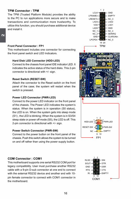
TPM Connector : TPMThe TPM (Trusted Platform Module) provides the ability to the PC to run applications more secure and to make transactions and communication more trustworthy. To utilize this function, you should purchase additional device and install it.
front Panel Connector : fP1This motherboard includes one connector for connecting the front panel switch and LED Indicators.
Hard Disk leD Connector (HDD-leD)Connect to the chassis front panel IDE indicator LED. It indicates the active status of the hard disks. This 2-pin connector is directional with +/- sign.
Reset Switch (ReSeT-SW)Attach the connector to the Reset switch on the front panel of the case; the system will restart when the switch is pressed.
Power leD Connector (PWR-leD)Connect to the power LED indicator on the front panel of the chassis. The Power LED indicates the system’s status. When the system is in operation (S0 status), the LED is on. When the system gets into sleep mode (S1) , the LED is blinking; When the system is in S3/S4 sleep state or power off mode (S5), the LED is off. This 2-pin connector is directional with +/- sign.
Power Switch Connector (PWR-SW)Connect to the power button on the front panel of the chassis. Push this switch allows the system to be turned on and off rather than using the power supply button.
CoM Connector : CoM1This motherboard supports one serial RS232 COM port for legacy compatibility. User must purchase another RS232 cable with a 9-pin D-sub connector at one end to connect with the external RS232 device and another end with 10-pin female connector to connect with COM1 connector in the motherboard.
HDD-LED
RESET-SW
NC
+-
PWR-SW
+
-PWR-LED
EMPTY
1 2
109
FP1
RLSDSOUT
RI
GNDRTS
DSRDTR
CTSEMPTY
SIN1 2
109COM1
LCLKLFRAMEnLRESETn
LAD3VDD
LAD0
NC_2NC_1
GNDLPCPDn
GNDEMPTY
LAD2NC_3
LAD1GNDNC_4SERIRQCLKRUNinNC_5
1 2
19 20
TPM

17
2
17
Speaker Connector : SPeAKeRThe speaker connector is used to connect speaker of the chassis.
fan Connectors : CPU_fAN, SYS_fAN1There are two main fan headers on this motherboard. The fan speed can be controlled and monitored in “PC Health Status” section of the BIOS Setup. These fans can be automatically turned off after the system enters S3, S4 and S5 sleeping states.
NC
SPKJEMPTY
SPEAKERSPKJ
1234
CPU_FAN/SYS_FAN1
GNDPOWERSENSECONTROL
1

18
2
18
2-5 JumpersFor some features needed, users can change the jumper settings on this motherboard to modify them. This section explains how to use the various functions of this motherboard by changing the jumper settings. Users should read the following content carefully prior to modifying any jumper setting.
Description of Jumpers1. For any jumper on this motherboard, pin 1 can be identified by the bold silkscreen next to it.
However, in this manual, pin 1 is simply labeled as “1”.2. The following table explains different types of the jumper settings. "Closed" means placing a jumper
cap on the two pins to temporarily short them. The shorting can also be done by touching two pins by a screwdriver for a few seconds, but using jumper cap is recommended. It can prevent hazardous ESD (Electrical Static Discharge) problem.
Clear CMoS Jumper: ClR_CMoS
The motherboard uses CMOS RAM to store the basic hardware information (such as BIOS data, date, time information, hardware password... etc.). Clear CMOS data is the fast way to go back to factory default when the BIOS settings were mistakenly modified.
The steps to clear CMOS data are : 1. Turn off the computer, unplug the power cord from the power outlet.2. Remove jumper cap from pins 2-3, put it onto pins 1-2 to short them. This will clear CMOS
data.3. Return the setting to its original with pins 2-3 closed.4. Plug in the power cord to your computer and turn it on.5. Go to BIOS Setup to configure new system as described in next chapter.
Clear
321
Normal(Default)
321
CLR_CMOS
Jumper Diagram Definition Description
1-2 Set Pin 1 and Pin 2 closed
2-3 Set Pin 2 and Pin 3 closed1
1
1
■ Disconnect the power cable before adjusting the jumper settings. ■ Do not clear the CMOS while the system is turned on.
WARNING!

19
2
19
Intel® Me Jumper: MfG
This motherboard uses MFG jumper to enable or disable Intel® Management Engine function. Intel® Management Engine (ME) is an embedded microcontroller located in Intel chipset. It provides latest IT management features such as Intel® AMT, that allows to improve management of corporate assets. Set the jumper to pins 1-2, you can enable the Intel® Management Engine function. Set the jumper to pins 2-3, you can disable the Intel® Management Engine function.
Enable(Default)
123
Disable123
MFG
Before flashing BIOS ROM, you need to set MFG jumper to pins 2-3 first.
CAUT
ION
!

This chapter tells how to change system settings through the BIOS Setup menus. Detailed descriptions of the BIOS parameters are also provided.You have to run the Setup Program when the following cases occur :1. An error message appears on the screen during the system
Power On Self Test (POST) process.2. You want to change the default CMOS settings.
This chapter includes the following information :■ Enter BIOS Setup■ Main Menu■ System Information■ Advanced BIOS Features■ Fox Central Control Unit■ Advanced Chipset Features ■ Integrated Peripherals■ Power Management Setup■ PC Health Status■ BIOS Security Features■ Load Optimal Defaults■ Save & Exit Setup■ Exit Without Saving
Since BIOS could be updated some other times, the BIOS information described in this manual is for reference only. We do not guarantee the content of this manual will remain consistent with the newly released BIOS at any given time in the future. Please visit our website for updated manual if it is available.

3
21
enter bIoS Setup
The BIOS is the communication bridge between hardware and software, correctly setting up the BIOS parameters is critical to maintain optimal system performance. Power on the computer, when the message "Press <Del> to enter Setup, <eSC> to boot menu" appears at the bottom of the screen, you can press <DEL> key to enter Setup.
Main MenuThe main menu allows you to select from a list of setup functions together with two exit choices. Use the arrow keys to select a specific item and press <Enter> to go to the sub-menu.Each item in the main menu is explained below:
► System InformationIt displays the basic system configuration, such as BIOS Version, memory size plus system date, time and Floppy drive. They all can be viewed or set up through this menu.
► Advanced BIOS FeaturesThe advanced system features can be set up through this menu. There are boot up settings.
► Fox Central Control UnitSome special proprietary features (such as overclocking) can be set up through this menu.
► Advanced Chipset FeaturesThe values for the chipset can be changed through this menu, and the system performance can be optimized.
► Integrated PeripheralsAll onboard peripherals can be set up through this menu. There are IDE devices, Super I/O devices such as Serial I/O and other USB devices... etc.
We do not suggest that you change the default values in the BIOS Setup, and we shall not be responsible for any damage which resulted from the change you made.
CAUT
ION
!
CMOS Setup Utility - Copyright (C) 1985-2009, American Megatrends, Inc.
► System Information ► PC Health Status
► Advanced BIOS Features ► BIOS Security Features
► Fox Central Control Unit Load Optimal Defaults
► Advanced Chipset Features Save & Exit Setup ► Integrated Peripherals Exit Without Saving
► Power Management Setup
↑↓←→:Move Enter:Select +/-/:Value F10:Save ESC:Exit F1:General Help F9:Optimized Defaults
Configure Time and Date. Display System Information...
v02.67 (c) Copyright 1985-2009, American Megatrends, Inc.
► System Information

3
22
► Power Management SetupAll the items related with Green function features can be set up through this menu.
► PC Health StatusThis setup enables you to read/change Fan speeds, and displays temperatures and voltages of your CPU/System.
► BIOS Security FeaturesThe Supervisor/User password can be set up through this menu to prevent unauthorized use of your computer. If you set a password, the system will ask you to key in correct password before boot or access to Setup.
► Load Optimal DefaultsThe optimal performance settings can be loaded through this menu. However, it may offer bet-ter performance in some ways (such as less I/O cards, less memory ...etc.), still, it may cause problem if you have more memory or I/O cards installed. It means, if your system loading is heavy, set to optimal default may sometimes come out an unstable system. What you need now is to adjust BIOS setting one by one, trial and error, to find out the best setting for your current system.
► Save & Exit SetupSave setting values to CMOS and exit.
► Exit Without SavingDo not change anything and exit the setup.

3
23
System InformationThis sub-menu is used to set up the standard BIOS features, such as the date, time, memory and so on. Use the arrow up/down keys to select an item, then use the <+> or <-> keys to change the setting.
► System TimeThis item allows you to configure the desired time. Use [ENTER], [TAB] or [SHIFT-TAB] to select a field. Use [+] or [-] to input the value.The three fields of the setting are <hour> : <minute> : <second> respectively.
► System Date<weekday><month><date> <year> format.Day—weekday from Sun. to Sat., this message is automatically displayed by BIOS (Read Only).Month—month from 1 to 12.Date—date from 1 to 31.Year—year, set up by users.Use [ENTER], [TAB] or [SHIFT-TAB] to select a field. Use [+] or [-] to input the value.
► SATA 1/2/3/4/5/6While entering setup, BIOS automatically detects the presence of SATA devices. This itemdisplays the drive information of SATA devices.
► Halt OnThis category determines whether or not the computer will stop if an error is detected during powering up.[All Errors] : All errors can result in system halt.[All Errors But...] : All errors but keyboard or mouse can result in system halt. The halt condi-
tion can be enabled/disabled in the next three settings.► Keyboard
The system boot will not stop for a keyboard error if you enabled this item.► Mouse
The system boot will not stop for a mouse error if you enabled this item.► Model Name
CMOS Setup Utility - Copyright (C) 1985-2009, American Megatrends, Inc. System Information
System Time [15 : 40 : 49] Help Item System Date [Mon , 10/26/2009] Use [Enter], [TAB] ► SATA 1 [Not Detected] or [SHIFT-TAB] to ► SATA 2 [Not Detected] select a field. ► SATA 3 [Not Detected] ► SATA 4 [Not Detected] Use [+] or [-] to ► SATA 5 [Not Detected] configure system time. ► SATA 6 [Not Detected] Halt On [All Errors, But ...] Keyboard [Enabled] Mouse [Disabled] Model Name : H55MXV BIOS Version : 9A1F1D07 Memory : 2048MB MAC Address : 8E-00-00-00-8E-8E
↑↓←→:Move Enter:Select +/-/:Value F10:Save ESC:Exit F1:General Help F9:Optimized Defaults
09

3
24
Model name of this product.► BIOS Version
It displays the current BIOS version. User can check this information and discuss with the field service people if a BIOS upgrade is needed.
► MemoryThis item displays the current memory size. The size is depending on how many memory mod-ules were installed in your system before powering on.
► MAC AddressThis item shows the onboard LAN MAC address.

3
25
Advanced BIOS Features
CMOS Setup Utility - Copyright (C) 1985-2009, American Megatrends, Inc. Advanced BIOS Features
Quiet Boot [Enabled Help Item Bootup Num-Lock [On] PCI Latency Timer [64] ► Intel VT-d Configuration [Press Enter] ► Trusted Computing [Press Enter]
↑↓←→:Move Enter:Select +/-/:Value F10:Save ESC:Exit F1:General Help F9:Optimized Defaults
[Enabled]
Disabled: Displaysnormal POST messages.Enabled: Displays OEMLogo instead of POST messages.
► Quiet BootThis item is used to enable/disable the quiet boot.[Disabled] : Displays the normal POST messages.[Enabled] : Displays OEM customer logo instead of POST messages.
► Bootup Num-LockThis item defines if the keyboard Num Lock key is active when your system is started. Theavailable settings are: On (default) and Off.
► PCI Latency TimerThis item is used to set the value in units of PCI clocks for PCI device latency timer register.
► Intel VT-d Configuration/Trusted ComputingPress <Enter> to go to relative submenu.
Intel VT-d Configuration CMOS Setup Utility - Copyright (C) 1985-2009, American Megatrends, Inc.
Intel VT-d Configuration
Help Item Intel VT-d
Disabled
Enabled
↑↓←→:Move Enter:Select +/-/:Value F10:Save ESC:Exit F1:General Help
F9:Optimized Defaults
[Disabled]Options

3
26
► Intel VT-dIntel® Virtualization Technology for Directed I/O (VT-d) can improve performance of I/O de-vices in virtualized environment. This item is used to enable/disable the VT-d feature.
Trusted Computing
CMOS Setup Utility - Copyright (C) 1985-2009, American Megatrends, Inc.Trusted Computing
Trusted Computing Help Item TCG/TPM Support Enable/Disable TPM TCG (TPM 1.1/1.2) support in BIOS
↑↓←→:Move Enter:Select +/-/:Value F10:Save ESC:Exit F1:General Help F9:Optimized Defaults
[No]
► TCG/TPM SupportTrusted Computing Group (TCG) members develop and promote open, vendor-neutral, industry standard specifications for trusted computing building blocks and software interfaces across multiple platformsTPM (Trusted Platform Module) is a specification promoted by TCG. A Trusted Platform Mod-ule offers facilities for secure generation of cryptographic keys.The TPM Work Group is chartered to create the Trusted Platform Module (TPM) specification. The definition of the TPM architecture comes from the TC and the TPM Work Group de-fines the implementation of that architecture. Work group members should have a working knowledge of security in relation to the design and usage of cryptographic modules. Members should also have a working knowledge of cryptographic techniques including public-key cryp-tography, cryptographic algorithms and protocols.This item is used to enable/disable the function of TCG/TPM support.

3
27
fox Central Control Unit
CMOS Setup Utility - Copyright (C) 1985-2009, American Megatrends, Inc. Fox Central Control Unit
► CPU Configuration Help Item Ratio Status: Unlocked (Min:09, Max:26) Ratio Actual Value: 26 Ratio CMOS Setting [26] Current DRAM Speed :1333MHz DRAM Frequency [Auto] Memory Timing by SPD [Auto]
↑↓←→:Move Enter:Select +/-/:Value F10:Save ESC:Exit F1:General Help F9:Optimized Defaults
[Press Enter]
Configure CPU.
► CPU ConfigurationPress <Enter> to go to relative submenu.
► Ratio CMOS SettingThis item is used to set the ratio between CPU Core Clock and the FSB Frequency. You can use [+] or [-] to adjust the value.
► DRAM FrequencyThis item is used to adjust the memory speed. Select [Auto] for SPD enable mode. You can select a value manually such as [800 MHz], [1067 MHz] and [1333MHz]..
► Memory Timing by SPDThis item is used to enable/disable provision of DRAM timing by SPD device. The SerialPresence Detect (SPD) device is a small EEPROM chip, mounted on a memory module. It contains important information about the module's speed, size, addressing mode and various other parameters, so that the motherboard memory controller (chipset) can better access the memory device.Select [Auto] for SPD enable mode.Select [Manual] to set the parameters by yourself.The following 10 settings are valid only when the Memory Timing by SPD is set to [Manual].
► DRAM tCLThe number of memory clocks it takes a DRAM to return data after the read CAS_L is assert-ed depends on the memory clock frequency. The value that BIOS programs into the memory controller is a function of the target clock frequency. The target clock frequency is determined from the supported CAS latencies at given clock frequencies of each DIMM.
► DRAM tRAS (Active-to-Precharge Delay)This item allows you to set the minimum RAS# active time (in clock cycles).
► DRAM tRP (Precharge Command Period)This item allows you to select the row precharge time (in clock cycles).
► DRAM tRCD (RAS-to-CAS Delay) This item allows you to select a delay time (in clock cycles) between the CAS# and RAS# strobe signals.
3
28
► DRAM tWR (Write Recovery)This item allows you to select the write recovery time (in clock cycles).
► DRAM tRFC(Auto-Refresh-to-Active/Auto-Refresh Command Period)Refresh to Refresh or Refresh to Active command interval.
► DRAM tWTR (Internal Write to Read Command Delay)This item allows you to select a delay time (in clock cycles) between sending the last data from a write operation to the memory and issuing a read command.
► DRAM tRRD (Active-to-Active of a Different Bank)This item allows you to select a delay time (in clock cycles) between the RAS# and RAS# strobe signals.
► DRAM tRTP (Internal Read to Precharge Command Delay)This item allows you to set the delay time (in clock cycles) between read command and pre-charge command.
► DRAM tFAW(Four Active Window Delay)Specifies the time window in which four activates are allowed the same rank.
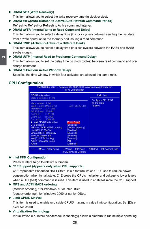
CPU Configuration
CMOS Setup Utility - Copyright (C) 1985-2009, American Megatrends, Inc.CPU Configuration
CPU Configuration Help Item Module Version : 01.08
Manufacturer : Intel Intel(R) Core(TM) i5 CPU 670 @3.47GHz Frequency :3.47GHz BCLK Speed :133MHz Cache L1 : 128 KB Cache L2 :512 KB Cache L3 :4096 KB ► Intel PPM Configuration C1E Support [Enabled] MPS and ACPI MADT ordering [Modern ordering] Limit CPUID MaxVal [Disabled] Virtualization Technology [Enabled] Execute Disable Bit [Enabled] Intel(R) HT Technology [Enabled] Active Processor Cores [All] A20M [Disabled] ↑↓←→:Move Enter:Select +/-/:Value F10:Save ESC:Exit F1:General Help F9:Optimized Defaults
[Press Enter]
Configure CPU EISTand C-statefunction
► Intel PPM ConfigurationPress <Enter> to go to relative submenu.
► C1E Support (Appears only when CPU supports)C1E represents Enhanced HALT State. It is a feature which CPU uses to reduce powerconsumption when in halt state. C1E drops the CPU’s multiplier and voltage to lower levelswhen a HLT (halt) command is issued. This item is used to enable/disable the C1E support.
► MPS and ACPI MADT ordering[Modern ordering] : for Windows XP or later OSes.[Legacy ordering] : for Windows 2000 or earlier OSes.
► Limit CPUID MaxValThis item is used to enable or disable CPUID maximum value limit configuration. Set [Disa-bled] for WinXP.
► Virtualization TechnologyVirtualization (i.e. Intel® Vanderpool Technology) allows a platform to run multiple operating

3
29
systems and applications in independent partitions or “containers.” One physical compute system can function as multiple “virtual” systems. Vanderpool Technology can help improve future virtualization solutions. This item will be displayed only when the CPU is supporting this feature and the setting is used to enable/disable it.
► Execute Disable BitThis item is used to enable/disable the Execute Disable Bit feature.Intel's Execute Disable Bit functionality can help prevent certain classes of malicious buffer overflow attacks when combined with a supporting operating system. Execute Disable Bit allows the processor to classify areas in memory by where application code can execute and where it cannot. When a malicious worm attempts to insert code in the buffer, the processor disables code execution, preventing damage and worm propagation. Replacing older computers with Execute Disable Bit-enabled systems can halt worm attacks, reducing the need for virus-related repairs. By combining Execute Disable Bit with anti-virus, firewall, spyware removal, e-mail filtering software, and other network security measures, IT managers can free IT resources for other initiatives.
► Intel(R) HT TechnologyThis item is used to enable/disable the Hyper Threading Technology feature.
► Active Processor CoresThis item is used to set the number of cores to enable in each processor package.
► A20MLegacy OSes and APs may need A20M enabled.
Intel PPM Configuration
► EIST Function You can select the EIST (Processor Power Management, PPM) through this item.
CMOS Setup Utility - Copyright (C) 1985-2009, American Megatrends, Inc.Intel PPM Configuration
Intel PPM Configuration Help Item EIST Function [Enabled] Intel(R) TurboMode tech [Enabled] Factory default TDC limit value : 424 Factory default TDC limit value : 584 Intel(R) C-STATE Technology [Enabled] CState Package Limit setting [Auto] C3 State [ACPI C2] C6 State [Enabled] C1 Auto Demotion [Enabled] C3 Auto Demotion [Enabled]
↑↓←→:Move Enter:Select +/-/:Value F10:Save ESC:Exit F1:General Help F9:Optimized Defaults
[Enabled] DisabledEnabled

3
30
Enhanced Intel SpeedStep® technology (EIST) allows the system to dynamically adjust processor voltage and core frequency, which can result in decreased average power consumption and decreased average heat production. There are some system require-ments must be met, including CPU, chipset, motherboard, BIOS and operation system. Please refer to Intel Website for more information.
CAUT
ION
!
► Intel(R) TurboMode techTurbo mode allows processor cores to run faster than its marked frequency in specific condi-tion.
► Intel(R) C-STATE TechnologyThis item is used to enable/disable C-State. C-State means CPU idle is set to C2/C3/C4.
► CState package limit settingThis item appears only when the Intel(R) C-STATE Technology is set to “Enabled”. It is used to select the C-State mode, set to “Auto” can allow BIOS to detect the C-State mode that sup-ported by your CPU.
► C3 StateThis item is used to enable/disable C3 State.
► C6 StateThis item is used to enable/disable C6 State.
► C1 Auto DemotionWhen enabled, CPU will conditionally demote C3/C6/C7 requests to C1 based on uncore auto-demote information.
► C3 Auto DemotionWhen enabled, CPU will conditionally demote C6/C7 requests to C3 based on uncore auto-demote information.

3
31
Advanced Chipset Features
CMOS Setup Utility - Copyright (C) 1985-2009, American Megatrends, Inc. Advanced Chipset Features
IMC Type : *Dale Family IMC Help Item Management Engine Version : 6.0.2.1194 Memory Remap Feature [Enabled] PCI MMIO Allocation: 4GB To 3328MB Initiate Graphic Adapter [PEG/PCI] SLP_S4# Min. Assertion Width [1 to 2 seconds]
↑↓←→:Move Enter:Select +/-/:Value F10:Save ESC:Exit F1:General Help F9:Optimized Defaults
[Disabled]ENABLE: Allowremapping ofoverlapped PCI memoryabove the totalphysical memory.
DISABLE: Do not allowremapping of memory.
► Memory Remap FeatureThis item is used to enable/disable memory remapping around memory hole.PCI doesn't actually care much which addresses are used, but by convention the PC platform puts them at the top of the 32-bit address space. For many years it wasn't possible or practical to put that much RAM into a PC. But now it is, so it's up to the memory controller and host bridge to figure out what to do. Many systems cause that high RAM to simply be ignored, resulting in the loss of effective RAM. More complex systems will take the RAM that would occupy that 3.5-4GB address space and re-map it into the 4.0-4.5GB address space. The RAM doesn't care because it's just an array of storage cells, it's up to the memory controller to associate addresses with those storage cells. Of course, that only works if you're using a 64-bit (or 32bit physical address extension (PAE) enabled) OS that can deal with physical addresses larger than 32 bits. Once this option is enabled, BIOS will display the true size of memory installed.
► Initiate Graphic Adapter This item is used to select which graphics controller is used as the primary boot device. ► SLP_S4# Min. Assertion Width
SLP_S4# is a signal for power plane control. This signal shuts off power to all non-critical systems when in the S4 (Suspend to Disk) or S5 (Soft Off) state.This setting indicates the minimum assertion width of the SLP_S4# signal to ensure that the DRAMs have been safely power-cycled. Setting values are: [4 to 5 seconds], [3 to 4 seconds], [2 to 3 seconds], [1 to 2 seconds].

3
32
Integrated Peripherals CMOS Setup Utility - Copyright (C) 1985-2009, American Megatrends, Inc.
Integrated Peripherals
► IDE Configuration [Press Enter] Help Item ► OnBoard Configuration [Press Enter] ► SuperIO Configuration [Press Enter] Configure the IDE ► USB Configuration [Press Enter] Device(s).
↑↓←→:Move Enter:Select +/-/:Value F10:Save ESC:Exit F1:General Help F9:Optimized Defaults
[Press Enter]
► IDE Configuration/OnBoard Configuration/SuperIO Configuration/USB Configuration
Press <Enter> to go to relative submenu.
IDE Configuration CMOS Setup Utility - Copyright (C) 1985-2009, American Megatrends, Inc.
IDE Configuration
Configure SATA as [IDE] Help Item SATA#1 IDE Configuration [Enhanced] SATA#2 IDE Configuration [Enhanced] IDE Detect Time Out [35]
↑↓←→:Move Enter:Select +/-/:Value F10:Save ESC:Exit F1:General Help F9:Optimized Defaults
[IDE]
Options
► Configure SATA asThis item is used to set the operation mode of your SATA ports 1, 2, 3, 4, 5, 6. Set to [IDE] can configure the SATA ports to support IDE mode.
► SATA#1 IDE ConfigurationSATA#1 are the SATA ports 1, 2, 3, 4 of the motherboard. This item allows you select the mode of the SATA ports. Setting values are: [Compatible], [Enhanced].
► SATA#2 IDE ConfigurationSATA#2 are the SATA ports 5,6 of the motherboard. This item allows you select the mode of the SATA ports. Setting values are: [Disabled], [Enhanced].
IDEDisabled

3
33
► IDE Detect Time OutThis item is used to select the time out value for detecting ATA/ATAPI devices. If the checking time is over the set value, the system will skip it.
OnBoard Configuration CMOS Setup Utility - Copyright (C) 1985-2009, American Megatrends, Inc.
OnBoard Configuration
OnBoard Audio Controller Help Item OnBoard LAN Controller [Enabled] OnBoard LAN Boot ROM [Disabled] Enabled Disabled
↑↓←→:Move Enter:Select +/-/:Value F10:Save ESC:Exit F1:General Help F9:Optimized Defaults
[Enabled]
Options
► OnBoard Audio ControllerThis item is used to enable or disable the HD Audio controller.
► OnBoard LAN ControllerThis item is used to enable or disable the onboard LAN controller.
► OnBoard LAN Boot ROMThis item is used to enable or disable the onboard LAN boot optional ROM. A LAN boot ROMlets you set up a diskless workstation on the network. By installing a boot ROM in the networkboard, you can enable a client PC system on the network to be booted remotely.
SuperIO Configuration CMOS Setup Utility - Copyright (C) 1985-2009, American Megatrends, Inc.
SuperIO Configuration
SuperIO Configuration Help Item Serial Port1 Address Allows BIOS to Select Serial Port1 Mode [Normal] Serial Port1 Base Parallel Port Address [378] Addresses. Parallel Port Mode [Normal] Parallel Port IRQ [IRQ7] OnBoard CIR Port [Disabled]
↑↓←→:Move Enter:Select +/-/:Value F10:Save ESC:Exit F1:General Help F9:Optimized Defaults
[2F8/IRQ3]

3
34
► Serial Port1 AddressThis item is used to assign the I/O address and interrupt request(IRQ) for the onboard serial port1.
► Serial Port1 ModeThis item is used to set the mode for the onboard serial port1. The available settings are:[Normal]: RS232 Mode.[IrDA]: An IrDA device for maximum 115200bit/s.[ASK IR]: A faster IrDA for 1152000bit/s.
► Parallel Port Address This item is used to assign the I/O address and interrupt request(IRQ) for the onboard parallel port.
► Parallel Port ModeThis item is used to select the operation modes for the onboard parallel (or Printer) port. They are [Normal] (default), [EPP], [ECP] and [ECP+EPP].
► Parallel Port IRQ This item is used to assign interrupt request(IRQ) for the onboard parallel port.
► OnBoard CIR PortThis item enables you to determine the transfer mode of the onboard infrared chip.
USB Configuration
CMOS Setup Utility - Copyright (C) 1985-2009, American Megatrends, Inc.USB Configuration
USB Configuration Help Item Module Version - 2.24.5-13.4
USB Devices Enabled : 2 Hubs Legacy USB Support USB 2.0 Controller Mode [HiSpeed] BIOS EHCI Hand-Off [Enabled] Legacy USB1.1 HC Support [Enabled]
↑↓←→:Move Enter:Select +/-/:Value F10:Save ESC:Exit F1:General Help F9:Optimized Defaults
[Enabled]
Enables support forlegacy USB. AUTOoption disableslegacy support ifno USB devices are connected.
► Legacy USB Support This item is used to enable the support for USB devices on legacy OS. If you have a USB keyboard or mouse, set to auto or enabled.► USB 2.0 Controller Mode This item is used to set the transmission rate mode of USB 2.0. The available settings are : [HiSpeed] in 480Mbps; [Full Speed] in 12Mbps. ► BIOS EHCI Hand-Off
Windows XP supports a number of features in the Enhanced Host Controller Interface (EHCI) specification, but there are a few features that are not implemented. Microsoft said preliminary support for EHCI BIOS handoff will be available in Windows XP SP2.

3
35
This item allows you to enable support for OS without EHCI hand-off feature.This is a workaround for OS without EHCI hand-Off support .The EHCI ownership change should claim by EHCI driver.
► Legacy USB1.1 HC Support This item is used to enable the support for USB devices on legacy OS. If you have a USB
keyboard or mouse, set to auto or enabled.

3
36
Power Management Setup
CMOS Setup Utility - Copyright (C) 1985-2009, American Megatrends, Inc. Power Management Setup
HPET Help Item ACPI Suspend Type [S3 (STR)] Power On after Power Fail [Power Off] Enable / Disable Green Mode [Enabled] USB Device Wakeup From S3 [Enabled] Resume by PCIE PME [Enabled] Resume by PCI Card [Enabled] Resume by PS2 Keyboard [Enabled] Resume by PS2 Mouse [Enabled] Resume by RTC [Disabled]
↑↓←→:Move Enter:Select +/-/:Value F10:Save ESC:Exit F1:General Help F9:Optimized Defaults
[Enabled]
ACPI (Advanced Configuration and Power Interface) is an open industry standard interfaces enabling OS-directed configuration, power management, and thermal management of mobile, desktop, and server platforms. It defines five sleeping states, they are :S1 - The S1 sleeping state is a low wake latency sleeping state. In this state, no system
context is lost (CPU or chip set) and hardware maintains all system context. (also called Power on Suspend)
S2 - The S2 sleeping state is a low wake latency sleeping state. This state is similar to the S1 sleeping state except that the CPU and system cache context is lost (the OS is respon-sible for maintaining the caches and CPU context). Control starts from the processor’s reset vector after the wake event.
S3 - The S3 sleeping state is a low wake latency sleeping state where all system context is lost except system memory. CPU, cache, and chip set context are lost in this state. Hardware maintains memory context and restores some CPU and L2 configuration context. Control starts from the processor’s reset vector after the wake event. (also called Suspend to RAM)
S4 - The S4 sleeping state is the lowest power, longest wake latency sleeping state supported by ACPI. In order to reduce power to a minimum, it is assumed that the hardware platform has powered off all devices. Platform context is maintained. (also called Suspend to Disk)
S5 - The S5 state is similar to the S4 state except that the OS does not save any context. The system is in the “soft” off state and requires a complete boot when it wakes. Software uses a different state value to distinguish between the S5 state and the S4 state to allow for initial boot operations within the BIOS to distinguish whether or not the boot is going to wake from a saved memory image.

3
37
► HPeTHPET stands for High Precision Even Timer. If you have the HPET disabled, then windowsdoes not have access to it and therefore falls back to less accurate timing methods. This itemis used to enable or disable the HPET Support.
► ACPI Suspend TypeThis item is used to set the energy saving mode of the ACPI function. When you select “S1(POS)” mode, the power is always on and computer can be resumed at any time. Whenyou select “S3 (STR)” mode, the power will be down after a period of time. The status of thecomputer before it entering STR will be saved in memory, and the computer can quickly returnto previous state when the STR function wakes.When you select “Auto”, it means OS will automatically take care and assign which mode is the most suitable now.
► Power On after Power FailThis item is used to set which state the PC will take with when it resumes after an AC powerloss.
► Geen ModeThis item is used to enable/disable the EUP(Energy Using Product) feature. When enable, thesuspend power of the chipset will be cut off in S4/S5 suspend mode in order to reduce the power consumption of motherboard; when disable, the suspend power is always on.
► USB Device Wakeup From S3This item is used to wake up the system by a USB device when it is staying at S3 state.
► Resume by PCIE PMEThis item is used to enable/disable the PCI Express device to generate a wake up.
► Resume by PCI CardThis item is used to enable/disable the PCI card to generate a wake up.
► Resume by PS2 KeyboardThis item is used to enable/disable the PS2 keyboard to generate a wake up.
► Resume by PS2 MouseThis item is used to enable/disable the PS2 mouse to generate a wake up.
► Resume by RTC This item is used to enable/disable RTC alarm event to generate a wake up.RTC is system real time clock.
► RTC Alarm Date(Days)When Resume by RTC is enabled, select a specific date to generate a wake up.
► RTC Alarm Time(HH:MM:SS)When Resume by RTC is enabled, select a specific time to generate a wake up.

3
38
PC Health Status
CMOS Setup Utility - Copyright (C) 1985-2009, American Megatrends, Inc.PC Health Status
Warning Temperature [Disabled] Help Item Shutdown Temperature [Disabled] Case Open Warning [Disabled] CPU Temperature :32 oC/89 oF System Temperature :27 oC/80 oF CPU Fan Speed :2109 RPM System Fan Speed :N/A
CPU Core :1.152 V DRAM Voltage :1.584 V +3.30V :3.264 V +5.00V :4.858 V +12.0V :12.460V CPU Smart Fan Control [Disabled] System Smart Fan Control [Disabled]
↑↓←→:Move Enter:Select +/-/:Value F10:Save ESC:Exit F1:General Help F9:Optimized Defaults
[Disabled]
Options
► Warning TemperatureThis option is used to set the warning temperature for the system. When the temperature ofCPU is higher than the set value, the motherboard will send out warning information.
► Shutdown TemperatureThis item is used to set the system temperature upper limit. When the temperature exceedsthe set value, the system will shut down automatically.This function works only when your operating system is supporting ACPI.
► Case Open WarningThis item is used to enable or disable case open warning function.
► CPU/System TemperatureThe CPU/System temperature are automatically detected and displayed by the system.
► CPU/System Fan SpeedThe CPU/System fan speed are automatically detected and displayed by the system.
► CPU Core/DRAM Voltage/+3.30V/+5.00V/+12.0VThe current voltages are automatically detected and displayed by the system.
► CPU Smart Fan/System Smart Fan ControlThis option is used to enable or disable smart fan function.The following 4 settings are valid only when Smart Fan Control is set to [Enabled].
► Fan OFF TemperatureIt allows you set a temperature value from which smart fan stops its operation.
► PWM Start TemperatureIt allows you set a temperature value from which smart fan starts its operation.
► Start PWM ValueIt allows you to set an initial PWM value to drive the fan when the temperature reaches Startvalue and smart fan begins its operation. The higher PWM value can achieve the faster fanspeed.
► Slope PWM ValueThe slope controls the PWM value being stepped up or down versus temperature changes.
Disabled50 oC/122 oF55 oC/131 oF60 oC/140 oF65 oC/149 oF70 oC/158 oF75 oC/167 oF80 oC/176 oF85 oC/185 oF

3
39
bIoS Security features
CMOS Setup Utility - Copyright (C) 1985-2005, American Megatrends, Inc.BIOS Security Features
Security Settings Help Item Supervisor Password : Not Installed Install or change the User Password : Not Installed password. Change Supervisor Password [Press Enter] Change User Password [Press Enter]
↑↓←→:Move Enter:Select +/-/:Value F10:Save ESC:Exit F1:General Help F9:Optimized Defaults
[Press Enter]
► Change Supervisor PasswordThis item is used to install or change supervisor password.After you input Supervisor password, it then will ask you to input user password optionally.
► Change User PasswordThis item is used to install or change user password.
Enter New Password :

3
40
load optimal DefaultsOptimal defaults are the best settings of this motherboard. Always load the Optimal defaults after updating the BIOS or after clearing the CMOS values.Select this option and press Enter, it will pop out a dialogue box to let you load the defaults. Select <OK> and then press <Enter> to load the defaults. Select <Cancel> and press <Enter>, it will not load. By this default, BIOS have set the optimal performance parameters of system to improve the performances of system components. But if the optimal performance parameters to be set cannot be supported by your hardware devices (for example, too many expansion cards were installed), the system might fail to work.
Save & Exit Setup When you select this option and press <Enter>, a message will be displayed in the center of the screen:Select [OK] to save your changes to CMOS and exit the pro-gram, select [Cancel] or <ESC> to return to the main menu.
Exit Without Saving If you select this option and press <Enter>, the following message will be displayed in the center of the screen:Select [OK] to exit CMOS without saving your modifications,select [Cancel] or <ESC> to return to the main menu.
Save configuration changes and exit setup?
[OK] [Cancel]
[OK]
Discard changes and exit setup?
[OK] [Cancel][OK]
Load Optimal Defaults?
[OK] [Cancel][OK]

The utility CD that came with the motherboard contains useful software and several utility drivers that enhance the motherboard features.
This chapter includes the following information:■ Utility CD content■ Install driver and utility■ FOX ONE■ FOX LiveUpdate■ FOX LOGO■ FOX DMI
Note : Because each module is independent, so the section number will be reorganized and unique to each module, please understand.

42
4
42
Utility CD contentThis motherboard comes with one Utility CD. You can simply put it into your CD/DVD-ROM drive, and the main menu will be displayed on your PC screen to guide you how to install.
1. Install DriverUse these options to install all the drivers for your system. You should install the drivers in order, and you need to restart your computer after all the drivers have been installed.
A. Intel Chipset DriverB. Realtek HDA Audio Driver C. Realtek LAN DriverD. Intel VGA DriverE. Intel Management Engine Driver
2. Software UtilitiesUse these options to install additional software programs. FOX ONE is a very powerful user inter-face program which allows you to change your system setting without going to BIOS. Some auto features help user to improve (or overclock) your system without being a computer literate.
A. FOX ONE B. FOX LiveUpdateC. FOX LOGOD. FOX DMIE. Microsoft DirectX 9.0*1
F. Adobe Acrobat ReaderG. Norton Internet Security
*1 : This item will appear in Windows XP operation system, but will not be shown in Windows Vista and Windows 7 operation system.

43
4
43
Install driver and utility1. Install DriverYou must click "Intel Chipset Driver" to install it first. After that, you can click "One Click Setup" to install all the other drivers left, or you can click on each individual driver to install it manually.
2. Install UtilityYou can select the specific utility to install.
Manual Instal-lation Step by Step
Automatic Installation by One Click.
Select to Install Utilities
Select to Install Drivers
Click to visit Foxconn's website
Browse CD
Exit the program
Drop to System Tray

44
4
44
foX oNeFOX ONE is a powerful utility for easily modifying system settings. It also allows users to monitor various temperature values, voltage values, frequencies and fan speeds at any time.
With FOX ONE, you can :■ Modify system performance settings, such as the CPU and memory bus speeds,
CPU voltages, fan speeds, and other system performance options.■ Monitor hardware temperatures, voltages, frequencies and fan speeds.
Supporting Operating Systems :■ Windows 2000 ■ Windows XP (32-bit and 64-bit)■ Windows 2003 (32-bit and 64-bit) ■ Windows Vista (32-bit and 64-bit)■ Windows 7 (32-bit and 64-bit)
Using FOX ONE :The very first time you run FOX ONE, F.I.S. Calibration function (FOX IntelligentStepping) will require you to calibrate the CPU’s loading. Click “OK” to proceedand start the Utility. F.I.S. is a feature of FOX ONE, which can automatically adjust your CPU clock based on your current system loading.
Before you running the FOX ONE program, the system parameters (such as CPU clock, voltage...etc.) are controlled by BIOS settings. After you run FOX ONE, it will take over, and the controlling right will be transferred to FOX ONE. Later, if you exit FOX ONE, then BIOS control will be back again.
CAUT
ION
!
Depending on hardware support, voltage monitoring and Fox Intelligent Stepping features are optional and only supported in some models. If the option is selectable, it also means the feature is supported.■ Voltage Monitoring is supported only in FOX ONE Premium & Deluxe products.■ Fox Intelligent Stepping is supported only in FOX ONE Deluxe products.
CAUT
ION
!

45
4
45
1. Main Page
ToolbarUse the toolbar to navigate to other pages.
Alert lampWhen the system is in healthy state, the color of alert lamp is green. When the system is in abnormal state, the alert lamp color is red.
Switch buttonClick this button, it will simplify the whole FOX ONE control panel to a smaller information bar (i.e. Simple Mode) as depicted below, you can drag this bar to any place on your screen to help you monitoring system status.
Click here to go back to FOX ONE full screen
Click here will drop the FOX ONE to Windows system tray
Exit FOX ONE
Show CPU Information Toolbar Alert Lamp
Switch Button
Exit Minimum
Homepage
Monitor Frequency/Voltage/Fan speed/Temperature value
Configuration
Skin Button

46
4
46
Skin buttonThere are more choices of FOX ONE screen panels. Click this button, you can select your favorite skin (FOX ONE Panel).
exitClick this button to exit the program.
MinimumClick this button to drop the FOX ONE to Windows system tray located at the lower right corner of your screen.
HomepageClick this button to visit Foxconn motherboard website :http://www.foxconnchannel.com
Apply the changes
Click the new skin picture to select the new skin
Cancel the changes

47
4
47
ConfigurationThis menu allows you to configure :1). Monitor interval (ms) :
This is to define the interval of different messages of system settings which are to be displayed on Simple Mode screen. Minimum value is 1 second.
2). Simple Mode :To select which message of system settings are to be displayed in the Simple Mode. Messages such as CPU frequency, voltage...etc., they can be displayed one by one in Simple Mode.
3). F.I.S. Calibration (FOX Intelligent Stepping, Optional)This function will re-calibrate the CPU's loading, and it may take several minutes to proceed. The FOX ONE calibration process will apply different loadings to your CPU, record PWM IC voltage together with the CPU clock running at these loadings, so it can define and estimate within a particular range of system loading, what the CPU clock should be.

48
4
48
Step 1 : Click Calibration icon, a message pops out to ask for continue. Select Yes.
Step 2 : After data is collected, it will ask you to restart your computer now.
Later on, when the FOX ONE program is activated, and F.I.S. feature (in CPU Page) is also enabled, FOX ONE will automatically adjust your CPU clock according to your system loadings. (Loadings are like Power Gaming, Data Mining...etc.)

49
4
49
2. CPU Page - CPU ControlThis page lets you select (or overclock) CPU clock to meet the current performance level of the system. The fastest and suitable CPU clock running for current system can be calculated by FOX ONE automatically or manually input by yourselves.
Manual :You can press the up/down button to adjust your CPU clock.Auto :Click this button to let FOX ONE check the highest CPU clock you can use. System will raise the CPU clock step by step until it hangs, you can then push the RESET button on your PC panel to restart the system. When system restarts, run FOX ONE again, it will display a recommended highest CPU clock for you, click <Yes> to apply it.
A message informs you to push RESET button later if the system hangs finally.Click Yes to continue.
Press Auto button to let FOX ONE check the highest CPU clock you can use.
Go to CPU page
FIS Features :Select the different benchmarks
Adjust by manual
Apply the changes
Reset the changes

50
4
50
You can see the system is raising CPU clock until the system hangs.Push RESET button on the front panel of your system to restart the computer.
Run FOX ONE program again, it will inform you the previous test found that 255MHz is the recommended CPU clock for your system.Click Yes to apply it to your system.
Now, your system is running at a CPU clock of 255MHz.

51
4
51
FOX Intelligent Stepping (F.I.S., Optional)Select FOX Intelligent Stepping will allow your system to automatically adjust your CPU clock rate based on different system loadings. For example, if you select Power Gaming, CPU clock will be driven to run at its maximum speed. While in Energy Saving, CPU will lower down its speed to a minimum. The four benchmarks - Power Gaming, Data Mining, Office and Energy Saving, the references of their system loading were calculated and defined in the FIS Calibration option of Configuration menu. Select Auto, CPU will automatically adjust its clock according to current system loading.
3. Frequency Page - Frequency ControlThis page lets you set memory and PCI Express frequencies by manual.
Go to Freq. page
Close this page
Reset the changes Apply the changes
Select the option you want to set
Adjust by manual

52
4
52
4. Limit Setting
4.1 Limit Setting - CPU TemperatureThis page lets you to set CPU high limit temperature and enable the alert function.
4.2 Limit Setting - System TemperatureThis page lets you to set system high limit temperature and enable the alert function.
Go to Limit Setting page
Set high limit by dragging the lever
Show current CPU temperature value
Enable alert function when the CPU temperature is higher than high limit value
Show current high limit value of the CPU temperature
Set high limit by dragging the lever
Show current system temperature value
Enable alert function when the system temperature is higher than high limit value
Show current high limit value of system temperature

53
4
53
4.3 Limit Setting - CPU FanThis page lets you to set CPU fan low limit rpm and enable the alert function.
4.4 Limit Setting - System FanThis page lets you to set system fan low limit rpm and enable the alert function.
Set low limit rpm by dragging the lever
Show current CPU fan rpm value
Enable alert function when the CPU fan runs slower than the low limit rpm value
Show current low limit rpm value of CPU fan
Set low limit rpm by dragging the lever
Show current system fan rpm value
Enable alert function when the system fan runs slower than low limit rpm value
Show current low limit rpm value of system fan

54
4
54
4.5 Limit Setting - FAN1 FanThis page lets you to set FAN1 fan low limit rpm and enable the alert function.
5. Voltage Page - Voltage Control (Optional)This page lets you set CPU voltage, memory voltage and North Bridge voltage manually. CPU voltage can be stepped up/down by a unit of 12.5mV, while memory is 0.05V/step, and North Bridge is 0.04V/step.
Set low limit rpm by dragging the lever
Show current FAN1 fan rpm value
Enable alert function when the FAN1 fan runs slower than low limit rpm value
Show current low limit rpm value of FAN1 fan
Go to Voltage page
Select the option you want to set
Adjust by manual
Reset the changes Apply the changes

55
4
55
6. Fan Page - Fan ControlThis page lets you enable Smart Fan function or set the fan speed by manual.When Smart Fan is selected, you must use a 4-pin CPU cooler in your system.
Go to Fan page
Set fan speed by dragging the lever
Enable or disable smart fan function
Apply the changes

56
4
56
FOX LiveUpdateFOX LiveUpdate is a useful utility to backup and update your system BIOS, drivers and utilities by local or online.
Supporting Operating Systems :■ Windows 2000■ Windows XP (32-bit and 64-bit)■ Windows 2003 (32-bit and 64-bit)■ Windows Vista (32-bit and 64-bit)■ Windows 7 (32-bit and 64-bit)
Using FOX LiveUpdate :
1. local Update1-1 local Update - bIoS InformationThis page lets you know your system BIOS information.
*** : please refer to the physical motherboard for detail.
Exit
Toolbar
Minimum
Show current BIOS information
Link to website
Please set the BIOS setting “BIOS Write Protect” or “Super BIOS Protect” to [Disabled] when running this application.
CAUT
ION
!
57
4
57
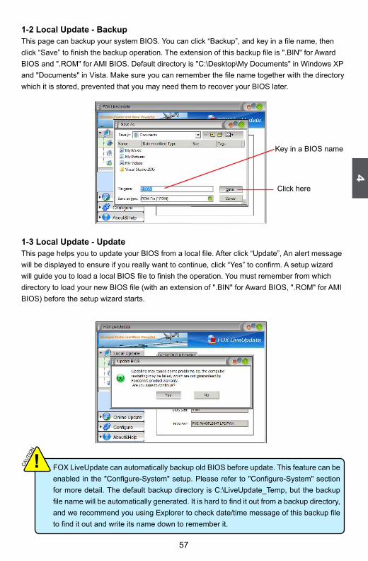
1-2 local Update - backupThis page can backup your system BIOS. You can click “Backup”, and key in a file name, then click “Save” to finish the backup operation. The extension of this backup file is ".BIN" for Award BIOS and ".ROM" for AMI BIOS. Default directory is "C:\Desktop\My Documents" in Windows XP and "Documents" in Vista. Make sure you can remember the file name together with the directory which it is stored, prevented that you may need them to recover your BIOS later.
1-3 local Update - UpdateThis page helps you to update your BIOS from a local file. After click “Update”, An alert message will be displayed to ensure if you really want to continue, click “Yes” to confirm. A setup wizard will guide you to load a local BIOS file to finish the operation. You must remember from which directory to load your new BIOS file (with an extension of ".BIN" for Award BIOS, ".ROM" for AMI BIOS) before the setup wizard starts.
Key in a BIOS name
Click here
FOX LiveUpdate can automatically backup old BIOS before update. This feature can be enabled in the "Configure-System" setup. Please refer to "Configure-System" section for more detail. The default backup directory is C:\LiveUpdate_Temp, but the backup file name will be automatically generated. It is hard to find it out from a backup directory, and we recommend you using Explorer to check date/time message of this backup file to find it out and write its name down to remember it.
CAUT
ION
!

58
4
58
2. online Update2-1 online Update - Update bIoSThis page lets you update your system BIOS from Internet. Click “start”, it will search the new BIOS from Internet. Then follow the wizard to finish the update operation.
2-2 Online Update - Update DriverThis page lets you update your system drivers from Internet. Click “start”, it will search the new drivers from Internet. Then follow the wizard to finish the update operation.
Click here
Current information
Search new BIOS from Internet
Browse detailed information
Update BIOS
Close the window
Select BIOS to update
Click here
Current information
Search new drivers from Internet

59
4
59
2-3 online Update - Update UtilityThis page lets you update utilities from Internet. Click “start”, it will search the new utilities from Internet. Then follow the wizard to finish the update operation.
Browse detailed informationInstall the selected driver
Close the window
Select the driver to update
Click here
Current information
Search new utilities from Internet
Browse detailed informationInstall the selected utility
Close the window
Select the utility to update

60
4
60
2-4 online Update - Update AllThis page lets you update your system drivers from Internet. Click “start”, it will search all new BIOS/drivers/utilities from Internet. Then follow the wizard to finish the update operation.
Click here
Current information
Search all new BIOS/drivers/utilities from Internet
Browse detailed BIOS information
Close the window
Browse detailed driver information
Browse detailed utility information

61
4
61
3. Configure3-1 Configure - optionThis page lets you set auto search options. After you enable the auto search function, FOX LiveUpdate will start its searching from Internet and if any qualified item found, it will pop out a message on the task bar to inform you to do the next step.
Double click on the icon as show below, you can see the detailed information.
Double click here
Apply the changes Reset to default value
Click here
Set auto search options
Select search which kind of versions
Set auto search the latest FOX LiveUpdate

62
4
62
When you enable "Auto Search FOX LiveUpdate", if your FOX LiveUpdate version is older, it will
auto search from internet and prompt you to install the new version.
3-2 Configure - SystemThis page lets you set the backup BIOS location and change different skin of the FOX LiveUpdate utility.
Prompt you to install the new FOX LiveUpdate
Click here
Set the location of download files or auto backup BIOS
Apply the changes Reset to default value
Determine if the FOX LiveUpdate can auto run when the system starts up

63
4
63
3-3 Configure - AdvanceThis page lets you select to flash BIOS / Boot Block and clear CMOS. If you choose Flash Boot Block, it means BIOS is not protective, and you must make sure the flash process is continuous and without any interruption.
4. About & HelpThis page shows some information about FOX LiveUpdate.
CAUT
ION
! We recommend that you had better keep the default setting unchanged to avoid any damage.
Click here
Select which BIOS ROM to flash(Only available to motherboard with backup BIOS ROM )
Apply the changes Reset to default value
Select to flash Boot Block Select to clear CMOS
Click here
Show information about FOX LiveUpdate

64
4
64
foX loGoFOX LOGO is a simple and useful utility to backup, change and delete the boot time Logo. The boot Logo is the image that appears on screen during POST (Power-On Self-Test).
You can prepare a JPG image (1024x768) file, then use FOX LOGO to open it and change the boot time Logo. Boot time Logo will be displayed if you enable the BIOS "Quiet Boot" setting in "Advanced BIOS Features" menu.
Supporting Operating Systems :■ Windows 2000■ Windows XP (32-bit and 64-bit)■ Windows 2003 (32-bit and 64-bit)■ Windows Vista (32-bit and 64-bit)■ Windows 7 (32-bit and 64-bit)
Using FOX LOGO:
Main Page
When you change Logo or delete current Logo, the system will flash BIOS file auto-matically. During this time, please DO NOT shut down the application and the system,
or the motherboard will be damaged seriously.
WARNING!
Minimize
Exit
Website
About
Backup
Change
Delete
Main screen

65
4
65
foX DMIFOX DMI is a full Desktop Management Interface viewer, and it provides three DMI data formats : Report, Data Fields and Memory Dump. Users can easily switch between the TabCtrl. With DMI information, system maker can easily analyze and troubleshoot your motherboard if there is any problem occurred.
Supporting Operating Systems :■ Windows 2000■ Windows XP (32-bit and 64-bit)■ Windows 2003 (32-bit and 64-bit)■ Windows Vista (32-bit and 64-bit)■ Windows 7 (32-bit and 64-bit)
Using FOX DMI:
Please operate this utility as the comments shows.
Click here to select the DMI Data formatyou need
Click here to select the type you want to view.