Embed Size (px)
Citation preview
Specialized Factory for Steel Products (Jeddah,Riyadh/KSA)Sigma Factoryِ for Steel Products (Dubai,Ajman,Umm Al Quwain /UAE)Specialized Factory for Steel Products (6th of October/Egypt)Specialized Factory for Steel Products (Amman/Jordan)
SFSP Metal Framing system provides an economical solution for electrical, mechanical and industrial supports with a wide variety of applications in the construction industry.
Metal Framing / Electrical Applications• Pipe & conduit supports • Tunnel pipe stanchions• Beam attachments• Pipe risers
Metal Framing / Industrial Applications• Racks and shelvings• Production line supports• Trolley systems• Wall framings
This catalogue is designed to be helpful to engineers and contractors in the application and selection of channel products for construction and maintenance.If a unique application requires a special product not included in this catalogue ,SFSP engineering personnel are ready to furnish design consultation and realistic cost estimates. In addition, know-how are available for your convenience.
Gypsum Boards are considered among the most economic and ideal way for wall partitioning. Easy to install, saves time and money, gypsum boards can also be used as a backing for wall treatments such as wall paper fabric tile and wood paneling or it can simply be painted. SFSP provides a com-plete product range for drywall and ceiling constructions. Uni Metal Studs, Runners, Furring Channels, Ceiling, Channel and Wall. Angles are among the range of products produced according to relevant standards to service the dry wall installers.
G y p s u m P r o f i l e sC a t a l o g
S F S P
2
SAUDI ARABIA
SYRIA
NAMO
EGYPT
JORDAN
IRAQ IRAN
KUWAIT
UAE
QATAR
Bahrain
Jeddah
Cairo
Ajman
Umm Al Quwain
Musaffah
Riyadh
Amman
YEMENSUDAN
LEBANON
6th of October
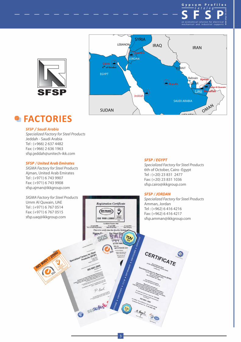
FACTORIES SFSP / Saudi ArabiaSpecialized Factory for Steel ProductsJeddah - Saudi ArabiaTel : (+966) 2 637 4482 Fax: (+966) 2 636 1963 [email protected]
SFSP / United Arab Emirates
SIGMA Factory for Steel ProductsAjman, United Arab EmiratesTel : (+971) 6 743 9907 Fax: (+971) 6 743 [email protected]
SIGMA Factory for Steel ProductsUmm Al Quwain, UAETel : (+971) 6 767 0514Fax: (+971) 6 767 [email protected]
SFSP / EGYPT
Specialized Factory for Steel Products6th of October, Cairo -EgyptTel : (+20) 23 831 2477 Fax: (+20) 23 831 [email protected]
SFSP / JORDAN
Specialized Factory for Steel ProductsAmman, JordanTel : (+962) 6 416 4216 Fax: (+962) 6 416 [email protected]
G y p s u m P r o f i l e sC a t a l o g
S F S P
www.sfs
p-ikk
.com
3
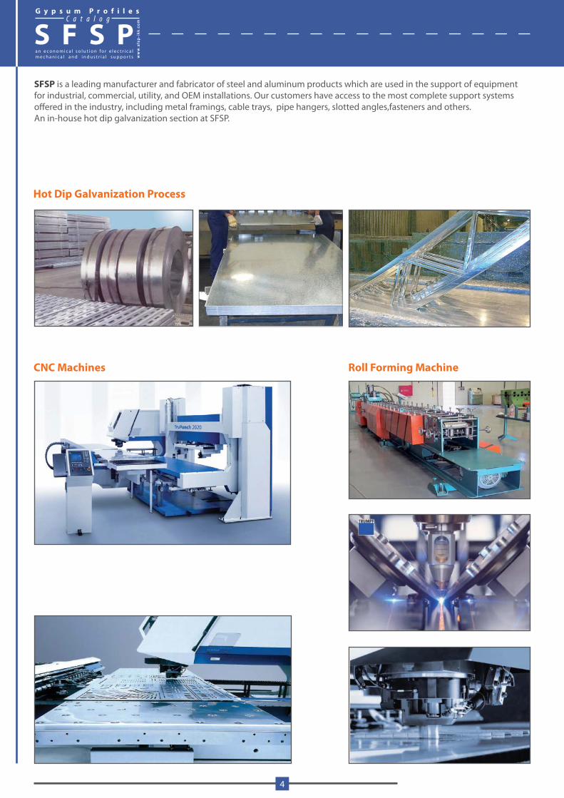
Hot Dip Galvanization Process
SFSP is a leading manufacturer and fabricator of steel and aluminum products which are used in the support of equipment for industrial, commercial, utility, and OEM installations. Our customers have access to the most complete support systems offered in the industry, including metal framings, cable trays, pipe hangers, slotted angles,fasteners and others.An in-house hot dip galvanization section at SFSP.
CNC Machines Roll Forming Machine
G y p s u m P r o f i l e sC a t a l o g
S F S P
4
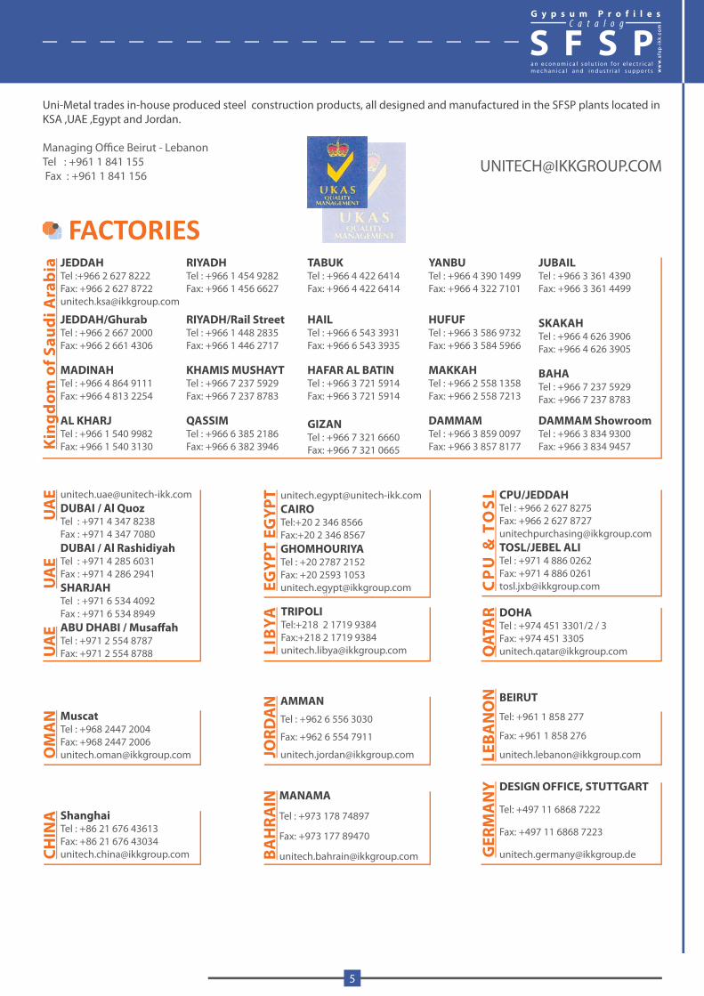
Uni-Metal trades in-house produced steel construction products, all designed and manufactured in the SFSP plants located in KSA ,UAE ,Egypt and Jordan.
Managing Office Beirut - Lebanon Tel : +961 1 841 155 Fax : +961 1 841 156
Kin
gdom
of S
audi
Ara
bia JEDDAH
Tel :+966 2 627 8222Fax: +966 2 627 [email protected]
JEDDAH/GhurabTel : +966 2 667 2000Fax: +966 2 661 4306
MADINAHTel : +966 4 864 9111Fax: +966 4 813 2254
AL KHARJTel : +966 1 540 9982Fax: +966 1 540 3130
RIYADH Tel : +966 1 454 9282Fax: +966 1 456 6627
RIYADH/Rail StreetTel : +966 1 448 2835Fax: +966 1 446 2717
KHAMIS MUSHAYTTel : +966 7 237 5929Fax: +966 7 237 8783
QASSIMTel : +966 6 385 2186Fax: +966 6 382 3946
GIZANTel : +966 7 321 6660Fax: +966 7 321 0665
TABUKTel : +966 4 422 6414Fax: +966 4 422 6414
HAILTel : +966 6 543 3931Fax: +966 6 543 3935
HAFAR AL BATINTel : +966 3 721 5914Fax: +966 3 721 5914
JUBAILTel : +966 3 361 4390Fax: +966 3 361 4499
BAHATel : +966 7 237 5929Fax: +966 7 237 8783
SKAKAHTel : +966 4 626 3906Fax: +966 4 626 3905
DAMMAM ShowroomTel : +966 3 834 9300Fax: +966 3 834 9457
YANBUTel : +966 4 390 1499Fax: +966 4 322 7101
MAKKAHTel : +966 2 558 1358Fax: +966 2 558 7213
DAMMAMTel : +966 3 859 0097Fax: +966 3 857 8177
HUFUFTel : +966 3 586 9732Fax: +966 3 584 5966
[email protected] / Al QuozTel : +971 4 347 8238Fax : +971 4 347 7080DUBAI / Al RashidiyahTel : +971 4 285 6031Fax : +971 4 286 2941SHARJAHTel : +971 6 534 4092Fax : +971 6 534 8949ABU DHABI / MusaffahTel : +971 2 554 8787Fax: +971 2 554 8788U
AE
UA
EU
AE
MuscatTel : +968 2447 2004Fax: +968 2447 [email protected]
MA
N
ShanghaiTel : +86 21 676 43613Fax: +86 21 676 [email protected]
INA
CPU/JEDDAHTel : +966 2 627 8275Fax: +966 2 627 [email protected]/JEBEL ALITel : +971 4 886 0262Fax: +971 4 886 [email protected]
PU
& T
OS
L
DOHATel : +974 451 3301/2 / 3Fax: +974 451 [email protected]
ATA
R
BEIRUT
Tel: +961 1 858 277
Fax: +961 1 858 276
NO
N
DESIGN OFFICE, STUTTGART
Tel: +497 11 6868 7222
Fax: +497 11 6868 7223
MA
NY
[email protected]:+20 2 346 8566Fax:+20 2 346 8567GHOMHOURIYATel : +20 2787 2152Fax: +20 2593 [email protected]
EGYP
TEG
YPT
TRIPOLITel:+218 2 1719 9384Fax:+218 2 1719 [email protected]
BYA
AMMANTel : +962 6 556 3030
Fax: +962 6 554 7911
AN
MANAMA
Tel : +973 178 74897
Fax: +973 177 89470
RAIN
FACTORIES
G y p s u m P r o f i l e sC a t a l o g
S F S P
www.sfs
p-ikk
.com
5
Materials
Mild Steel - Plain
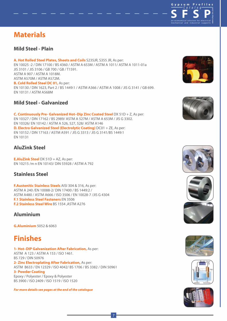
A. Hot Rolled Steel Plates, Sheets and Coils S235JR, S355 JR, As per:EN 10025 -2 / DIN 17100 / BS 4360 / ASTM A 653M / ASTM A 1011/ ASTM A 1011-01a JIS 3101 / JIS 3106 / GB 700 / GB / T1591.ASTM A 907 / ASTM A 1018M.ASTM A570M / ASTM A572M.B. Cold Rolled Steel DC 01, As per:EN 10130 / DIN 1623, Part 2 / BS 1449:1 / ASTM A366 / ASTM A 1008 / JIS G 3141 / GB 699.EN 10131 / ASTM A568M
Mild Steel - Galvanized C. Continuously Pre- Galvanized Hot–Dip Zinc Coated Steel DX 51D + Z, As per: EN 10327 / DIN 17162 / BS 2989/ ASTM A 527M / ASTM A 653M / JIS G 3302.EN 10326/ EN 10142 / ASTM A 526, 527, 528/ ASTM A146D. Electro Galvanized Steel (Electrolytic Coating) DC01 + ZE, As per: EN 10152 / DIN 17163 / ASTM A591 / JIS G 3313 / JIS G 3141/BS 1449:1EN 10131
AluZink Steel
E.AluZink Steel DX 51D + AZ, As per: EN 10215 /m n EN 10143/ DIN 55928 / ASTM A 792
Stainless Steel
F.Austenitic Stainless Steels AISI 304 & 316, As per: ASTM A 240 /EN 10088-2/ DIN 17400 / BS 1449:2 / ASTM A480 / ASTM A666 / ISO 3506 / EN 10028-7 /JIS G 4304F.1 Stainless Steel Fasteners EN 3506F.2 Stainless Steel Wire BS 1554 ,ASTM A276
Aluminium
G.Aluminium 5052 & 6063
Finishes1- Hot–DIP Galvanization After Fabrication, As per:ASTM A 123 / ASTM A 153 / ISO 1461.BS 729 / DIN 509762- Zinc Electroplating After Fabrication, As per:ASTM B633 / EN 12329 / ISO 4042/ BS 1706 / BS 3382 / DIN 509613- Powder CoatingEpoxy / Polyester / Epoxy & PolyesterBS 3900 / ISO 2409 / ISO 1519 / ISO 1520
For more details see pages at the end of the catalogue
G y p s u m P r o f i l e sC a t a l o g
S F S P
www.sfs
p-ikk
.com
7
STUD AND RUNNERSheet thickness and tolerance according to DIN 18182 part 1
ThicknessCode
Thicknesss Tolerance
o4 0.4 0,40 - 0,46
o5 0.5 0,46 - 0,55
o6 0.6 0,56 - 0,64
o7 0.7 0,66 - 0,74
10 1.0 0,91 - 1,09
20 2.0 1,86 - 2,14
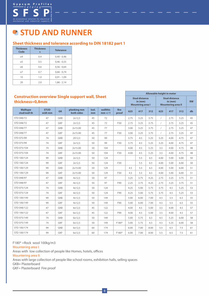
Construction overview Single support wall, Sheet thickness=0,8mm
Allowable height in meter
Stud distance in (mm)
Mountring area I
Stud distance in (mm)
Mountering area IIRW
Walltypestud/wall th
STUDwidt mm GK planking mm
both sidesIsol. mm
wallthicmm +/-1
fireproof 625 417 312 625 417 312 db
STD 048/72 47 GKB 2x12,5 45 72 2.75 3.25 3.75 / 2.75 3.25 45
STD 048/72 47 GKF 2x12,5 45 72 F30 2.75 3.25 3.75 / 2.75 3.25 45
STD 048/77 47 GKB 2x15.00 45 77 3.00 3.25 3.75 / 2.75 3.25 47
STD 048/77 47 GKF 2x15.00 45 77 F30 3.00 3.25 3.75 / 2.75 3.25 47
STD 075/99 74 GKB 2X12,5 50 99 3.75 4.5 5.25 3.25 4.00 4.75 47
STD 075/99 74 GKF 2x12,5 50 99 F30 3.75 4.5 5.25 3.25 4.00 4.75 47
STD 075/104 74 GKB 2x15.00 50 104 4.00 4.5 5.25 3.5 4.00 4.75 48
STD 075/104 74 GKF 2x15.00 50 104 F30 4.00 4.5 5.25 3.5 4.00 4.75 48
STD 100/124 99 GKB 2x12,5 50 124 5.5 6.5 4.00 5.00 6.00 50
STD 100/124 99 GKF 2x12,5 50 124 F30 5.5 6.5 4.00 5.00 6.00 50
STD 100/129 99 GKB 2x15.00 50 129 4.5 5.5 6.5 4.00 5.00 6.00 51
STD 100/129 99 GKF 2x15.00 50 129 F30 4.5 5.5 6.5 4.00 5.00 6.00 51
STD 048/97 47 GKB 4x12,5 50 97 3.25 3.75 4.25 2.75 3.25 3.75 51
STD 048/97 47 GKF 4x12,5 50 97 F90 2.25 3.75 4.25 2.75 3.25 3.75 51
STD 075/124 74 GKB 4x12,5 50 124 4.25 5.00 5.75 3.75 4.5 5.25 53
STD 075/124 74 GKF 4x12,5 50 124 F90 4.25 5.00 5.75 3.75 4.5 5.25 53
STD 100/149 99 GKB 4x12,5 50 149 5.00 6.00 7.00 4.5 5.5 6.5 55
STD 100/149 99 GKF 4x12,5 50 149 F90 5.00 6.00 7.00 4.5 5.5 6.5 55
STD 048/122 47 GKB 6x12,5 45 122 4.00 4.5 5.00 3.5 4.00 4.5 57
STD 100/122 47 GKF 6x12,5 45 122 F90 4.00 4.5 5.00 3.5 4.00 4.5 57
STD 075/149 74 GKB 6x12,5 50 149 5.00 5.75 6.5 4.5 5.25 6.00 58
STD 075/149 74 GKF 6x12,5 50 149 F180* 5.00 5.75 6.5 4.5 5.25 6.00 58
STD 100/174 99 GKB 6x12,5 60 174 6.00 7.00 8.00 5.5 6.5 7.5 61
STD 100/174 99 GKF 6x12,5 60 174 F180* 6.00 7.00 8.00 5.5 6.5 7.5 61
F180* =Rock wool 100kg/m3Mountering area I:Areas with low collection of people like Homes, hotels, officesMountering area II: Areas with large collection of people like school rooms, exhibition halls, selling spacesGKB= PlasterboardGKF= Plasterboard Fire proof
G y p s u m P r o f i l e sC a t a l o g
S F S P
8
Soundproofing in dBDescription of wallsystem Sound-proofing
planking with Plasterboard
planking in each side(mm)
Insulation (mm)
Wall Thickness(mm)
after DIN 18180 (dB)
planking plasterboard (dB)
Stud STD 048 / 72 12.5 45 72 40-43 41-46
Stud STD 075 / 99 12.5 50 99 40-44 44-49
Stud STD 075 / 99 12.5 60 99 41-44 47-52
Stud STD 100/ 124 12.5 45 124 42-45 46-49
Stud STD 100 / 124 12.5 80 124 42-48 49-53
Stud STD 048 / 97 2 x 12,5 45 97 47-52 51-54
Stud STD 075 / 124 2 x 12,5 45 124 48-52 51-57
Stud STD 075 / 124 2 x 12,5 60 124 49-53 56-57
Stud STD 100 / 124 2 x 12,5 45 124 48-55 52-57
Stud STD 100 / 124 2 x 12,5 80 124 50-56 56-58
Double studStud Std 048 + 048 / 150
2 x 12,5 2 x 45 150 59-60 62-64
Double studStud Std 075 + 075 / 203
2 x 12,5 60 203 57-58 64
Double studStud Std 075 + 075 / 203
2 x 12,5 2 x 60 203 58-60 64-66
Double studStud Std 100+ 100 / 253
2 x 12,5 80 253 58-60 65
Double studStud Std 100 + 100 / 253
2 x 12,5 2 x 80 253 60-63 67
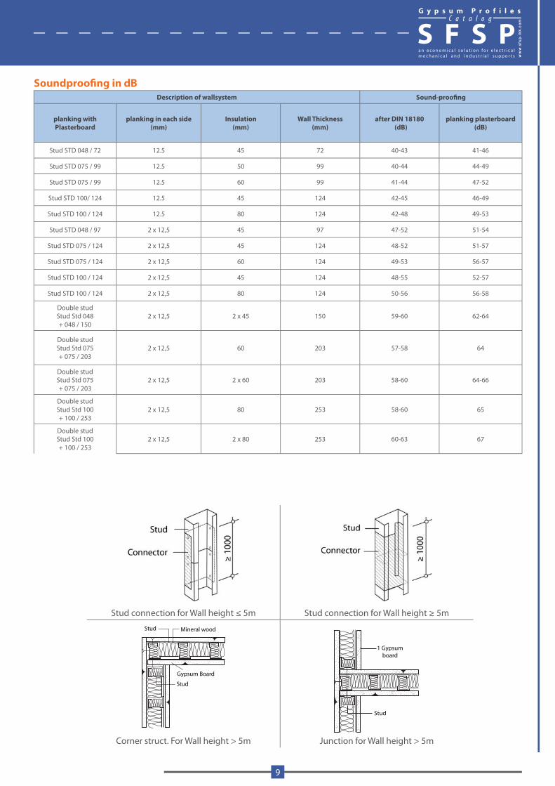
Stud connection for Wall height ≤ 5m Stud connection for Wall height ≥ 5m
Stud
Gypsum Board
Stud
Mineral wood
1 Gypsum board
Stud
Corner struct. For Wall height > 5m Junction for Wall height > 5m
G y p s u m P r o f i l e sC a t a l o g
S F S P
www.sfs
p-ikk
.com
9
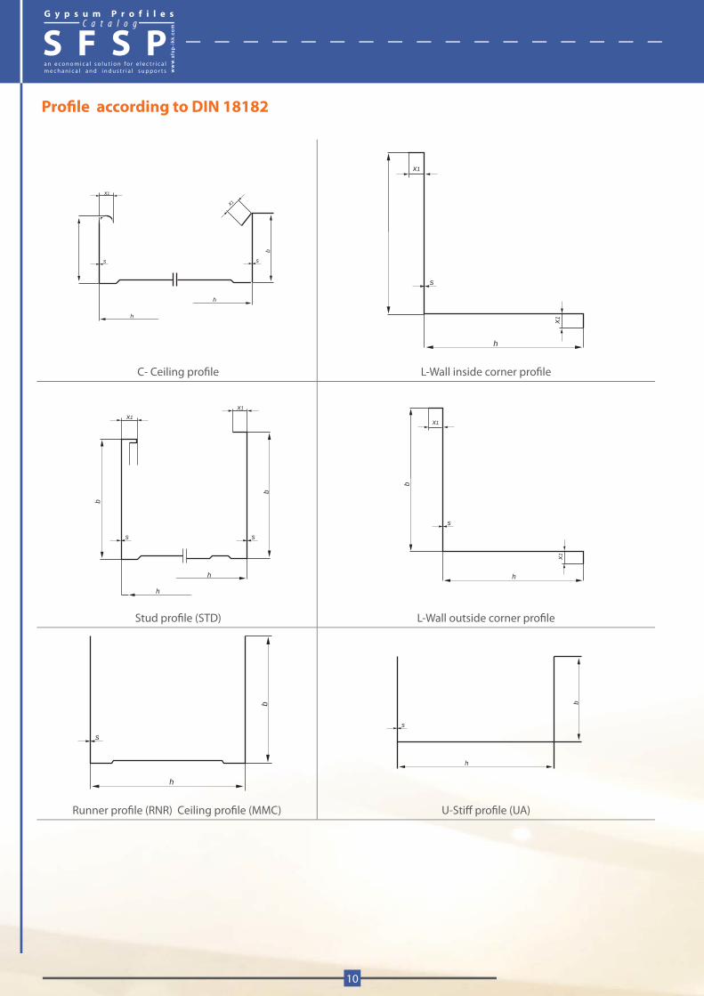
Profile according to DIN 18182
x1
x1
s s b
h
h
s
x1
x1
h
C- Ceiling profile L-Wall inside corner profile
b
s
h
h
s
b
x1
x1
s
x1
x1
b
h
Stud profile (STD) L-Wall outside corner profile
s
h
b
s
h
b
Runner profile (RNR) Ceiling profile (MMC) U-Stiff profile (UA)
G y p s u m P r o f i l e sC a t a l o g
S F S P
10
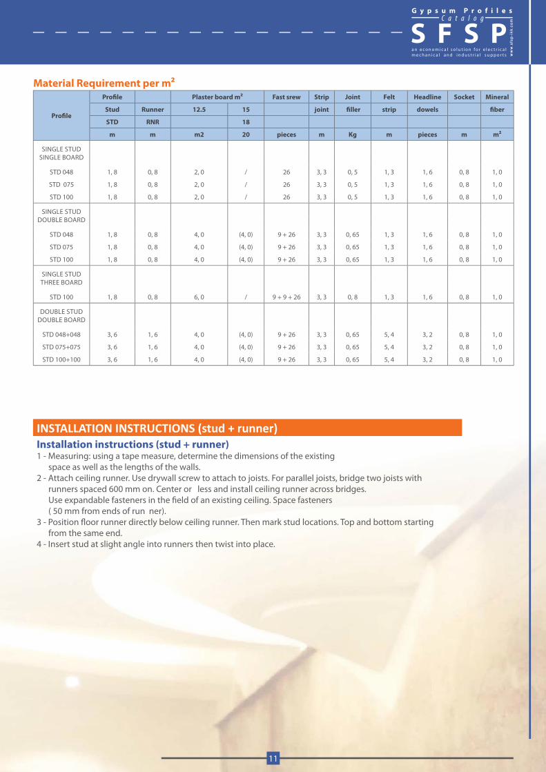
Material Requirement per m2
Profile
Profile Plaster board m2 Fast srew Strip Joint Felt Headline Socket Mineral
Stud Runner 12.5 15 joint filler strip dowels fiber
STD RNR 18
m m m2 20 pieces m Kg m pieces m m2
SINGLE STUDSINGLE BOARD
STD 048 1, 8 0, 8 2, 0 / 26 3, 3 0, 5 1, 3 1, 6 0, 8 1, 0
STD 075 1, 8 0, 8 2, 0 / 26 3, 3 0, 5 1, 3 1, 6 0, 8 1, 0
STD 100 1, 8 0, 8 2, 0 / 26 3, 3 0, 5 1, 3 1, 6 0, 8 1, 0
SINGLE STUDDOUBLE BOARD
STD 048 1, 8 0, 8 4, 0 (4, 0) 9 + 26 3, 3 0, 65 1, 3 1, 6 0, 8 1, 0
STD 075 1, 8 0, 8 4, 0 (4, 0) 9 + 26 3, 3 0, 65 1, 3 1, 6 0, 8 1, 0
STD 100 1, 8 0, 8 4, 0 (4, 0) 9 + 26 3, 3 0, 65 1, 3 1, 6 0, 8 1, 0
SINGLE STUDTHREE BOARD
STD 100 1, 8 0, 8 6, 0 / 9 + 9 + 26 3, 3 0, 8 1, 3 1, 6 0, 8 1, 0
DOUBLE STUDDOUBLE BOARD
STD 048+048 3, 6 1, 6 4, 0 (4, 0) 9 + 26 3, 3 0, 65 5, 4 3, 2 0, 8 1, 0
STD 075+075 3, 6 1, 6 4, 0 (4, 0) 9 + 26 3, 3 0, 65 5, 4 3, 2 0, 8 1, 0
STD 100+100 3, 6 1, 6 4, 0 (4, 0) 9 + 26 3, 3 0, 65 5, 4 3, 2 0, 8 1, 0
INSTALLATION INSTRUCTIONS (stud + runner)Installation instructions (stud + runner)1 - Measuring: using a tape measure, determine the dimensions of the existing space as well as the lengths of the walls.2 - Attach ceiling runner. Use drywall screw to attach to joists. For parallel joists, bridge two joists with runners spaced 600 mm on. Center or less and install ceiling runner across bridges. Use expandable fasteners in the field of an existing ceiling. Space fasteners ( 50 mm from ends of run ner).3 - Position floor runner directly below ceiling runner. Then mark stud locations. Top and bottom starting from the same end.4 - Insert stud at slight angle into runners then twist into place.
G y p s u m P r o f i l e sC a t a l o g
S F S P
www.sfs
p-ikk
.com
11
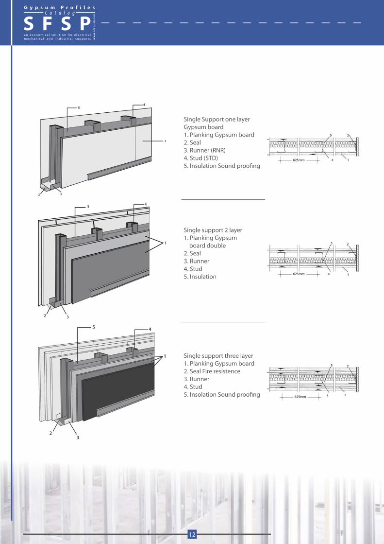
Single Support one layer Gypsum board1. Planking Gypsum board2. Seal3. Runner (RNR)4. Stud (STD)5. Insulation Sound proofing
Single support 2 layer1. Planking Gypsum board double2. Seal3. Runner4. Stud5. Insulation
Single support three layer 1. Planking Gypsum board2. Seal Fire resistence 3. Runner4. Stud5. Insolation Sound proofing
G y p s u m P r o f i l e sC a t a l o g
S F S P
12
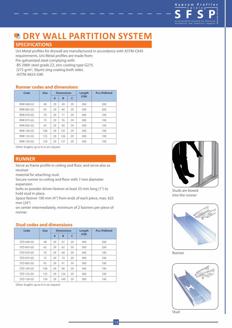
DRY WALL PARTITION SYSTEMSPECIFICATIONSUni Metal profiles for drywall are manufactured in accordance with ASTM-C645 requirements. Uni Metal profiles are made from:Pre-galvanized steel complying with:-BS 2989: steel grade Z2, zinc coating type G275. (275 g/m2, 36μm) zing coating both sides.-ASTM A653-G90
Runner codes and dimensionsCode Size Dimensions Length
(CM)Pcs./Palleted
A B C
RNR 048-GS 48 29 49 29 300 200
RNR 063-GS 63 29 64 29 300 200
RNR 070-GS 70 29 71 29 300 100
RNR 075-GS 75 29 76 29 300 100
RNR 092-GS 92 29 93 29 300 100
RNR 100-GS 100 29 101 29 300 100
RNR 125-GS 125 29 126 29 300 100
RNR 150-GS 150 29 151 29 300 100
Other lengths up to 6 m on request
RUNNERServe as frame profile in ceiling and floor, and serve also as receiver material for attaching stud. Secure runner to ceiling and floor with 7 mm diameter expansion bolts or powder driven fastner at least 25 mm long (1”) to hold stud in place.Space fastner 100 mm (4”) from ends of each piece, max. 625 mm (24”) on center intermediately, minimum of 2 fastners per piece of runner.
Stud codes and dimensionsCode Size Dimensions Length
(CM)Pcs./Palleted
A B C
STD 048-GS 48 29 47 29 300 200
STD 063-GS 63 29 62 29 300 200
STD 070-GS 70 29 69 29 300 100
STD 075-GS 75 29 74 29 300 100
STD 092-GS 92 29 91 29 300 100
STD 100-GS 100 29 99 29 300 100
STD 125-GS 125 29 124 29 300 100
STD 150-GS 150 29 149 29 300 100
Other lengths up to 6 m on request
Runner
Stud
Studs are boxedinto the runner
G y p s u m P r o f i l e sC a t a l o g
S F S P
www.sfs
p-ikk
.com
13
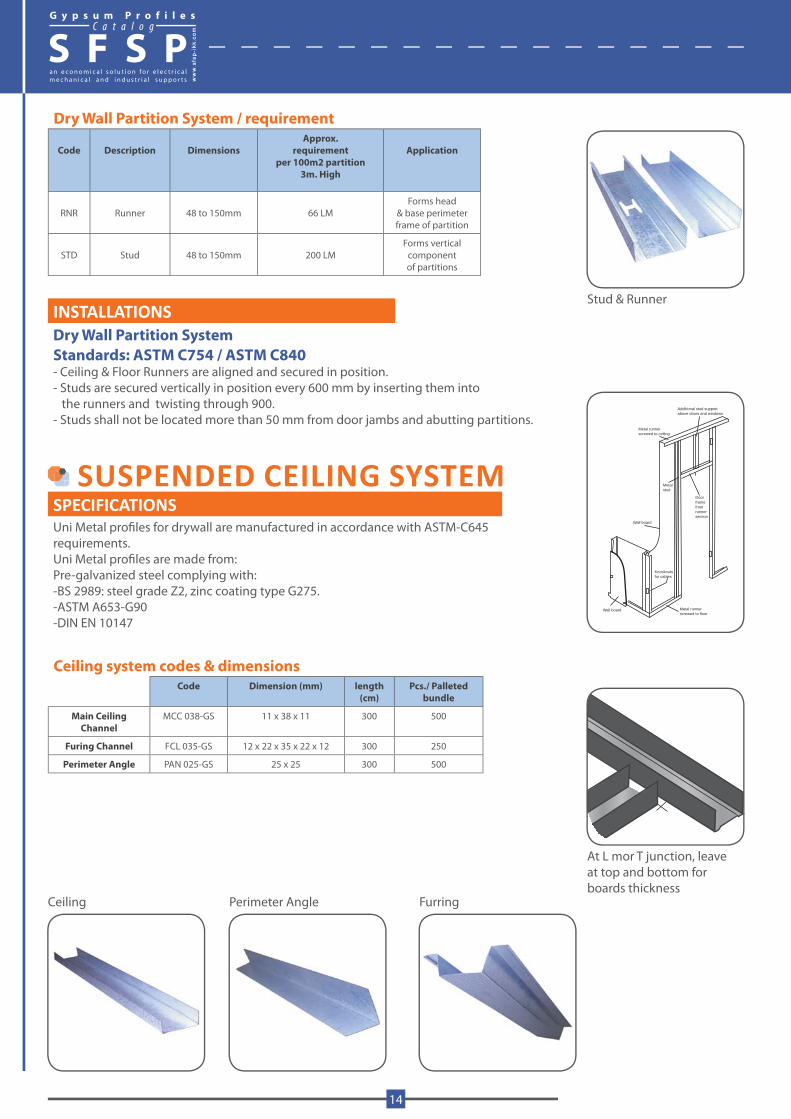
Additional stud supportabove doors and windows
Metal runnerscrewed to ceiling
Metal stud
Doorframefrom runnersection
Wall board
Knockoutsfor cables
Wall board Metal runnerscrewed to floor
Stud & Runner
At L mor T junction, leave at top and bottom for boards thickness
Perimeter Angle FurringCeiling
Dry Wall Partition System / requirement
Code Description DimensionsApprox.
requirementper 100m2 partition
3m. High
Application
RNR Runner 48 to 150mm 66 LMForms head
& base perimeterframe of partition
STD Stud 48 to 150mm 200 LM Forms vertical
componentof partitions
INSTALLATIONSDry Wall Partition SystemStandards: ASTM C754 / ASTM C840- Ceiling & Floor Runners are aligned and secured in position.- Studs are secured vertically in position every 600 mm by inserting them into the runners and twisting through 900.- Studs shall not be located more than 50 mm from door jambs and abutting partitions.
SUSPENDED CEILING SYSTEMSPECIFICATIONSUni Metal profiles for drywall are manufactured in accordance with ASTM-C645 requirements. Uni Metal profiles are made from:Pre-galvanized steel complying with:-BS 2989: steel grade Z2, zinc coating type G275.-ASTM A653-G90-DIN EN 10147
Ceiling system codes & dimensionsCode Dimension (mm) length
(cm)Pcs./ Palleted
bundle
Main CeilingChannel
MCC 038-GS 11 x 38 x 11 300 500
Furing Channel FCL 035-GS 12 x 22 x 35 x 22 x 12 300 250
Perimeter Angle PAN 025-GS 25 x 25 300 500
G y p s u m P r o f i l e sC a t a l o g
S F S P
14
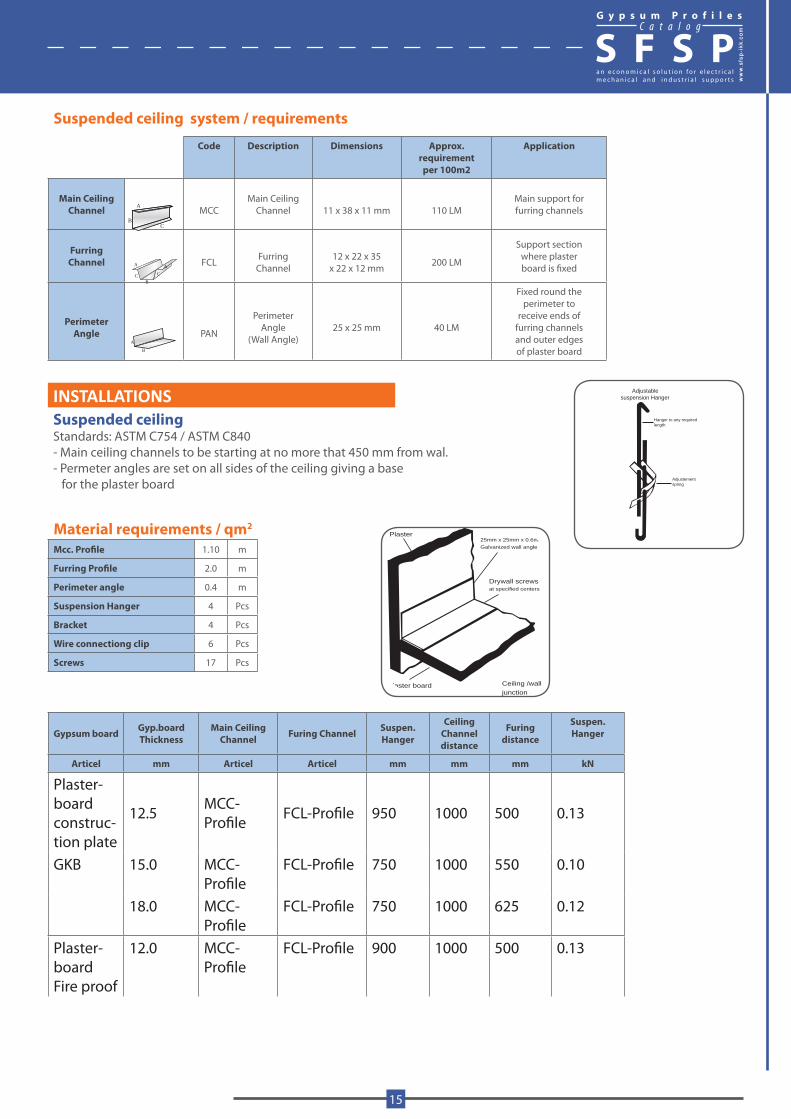
Suspended ceiling system / requirements
Code Description Dimensions Approx.requirementper 100m2
Application
Main CeilingChannel MCC
Main CeilingChannel 11 x 38 x 11 mm 110 LM
Main support forfurring channels
FurringChannel FCL Furring
Channel12 x 22 x 35
x 22 x 12 mm 200 LM
Support sectionwhere plasterboard is fixed
PerimeterAngle PAN
PerimeterAngle
(Wall Angle)25 x 25 mm 40 LM
Fixed round theperimeter to
receive ends offurring channelsand outer edgesof plaster board
INSTALLATIONSSuspended ceilingStandards: ASTM C754 / ASTM C840- Main ceiling channels to be starting at no more that 450 mm from wal.- Permeter angles are set on all sides of the ceiling giving a base for the plaster board
Material requirements / qm2
Mcc. Profile 1.10 m
Furring Profile 2.0 m
Perimeter angle 0.4 m
Suspension Hanger 4 Pcs
Bracket 4 Pcs
Wire connectiong clip 6 Pcs
Screws 17 Pcs
Gypsum board Gyp.board Thickness
Main Ceiling Channel Furing Channel Suspen.
Hanger
Ceiling Channel distance
Furing distance
Suspen. Hanger
Articel mm Articel Articel mm mm mm kN
Plaster-boardconstruc-tion plate
12.5 MCC-Profile FCL-Profile 950 1000 500 0.13
GKB 15.0 MCC-Profile
FCL-Profile 750 1000 550 0.10
18.0 MCC-Profile
FCL-Profile 750 1000 625 0.12
Plaster-board Fire proof
12.0 MCC-Profile
FCL-Profile 900 1000 500 0.13
Adjustablesuspension Hanger
Hanger to any requiredlength
Adjustementspring
Plaster board Ceiling /walljunction
Drywall screwsat specified centers
25mm x 25mm x 0.6mmGalvanized wall angle
Plaster
A
BC
A A
BC C
A
B
G y p s u m P r o f i l e sC a t a l o g
S F S P
www.sfs
p-ikk
.com
15

ACCESSORIES AND STANDARD TOOLS KIT
Corner tape
Wire connecting clip
Drywall screen
Framing Screw
Ready mix joint compound
Adjustable suspensionHanger
Powerscrewdriver
Taping knife
Measuring tape
Chalk line
Plumb line
Utility knife
BMI Level
Stainless steel finishing knife
Tinsnips Wallboard hand saw
Drywall joint tape
Bracket
G y p s u m P r o f i l e sC a t a l o g
S F S P
16
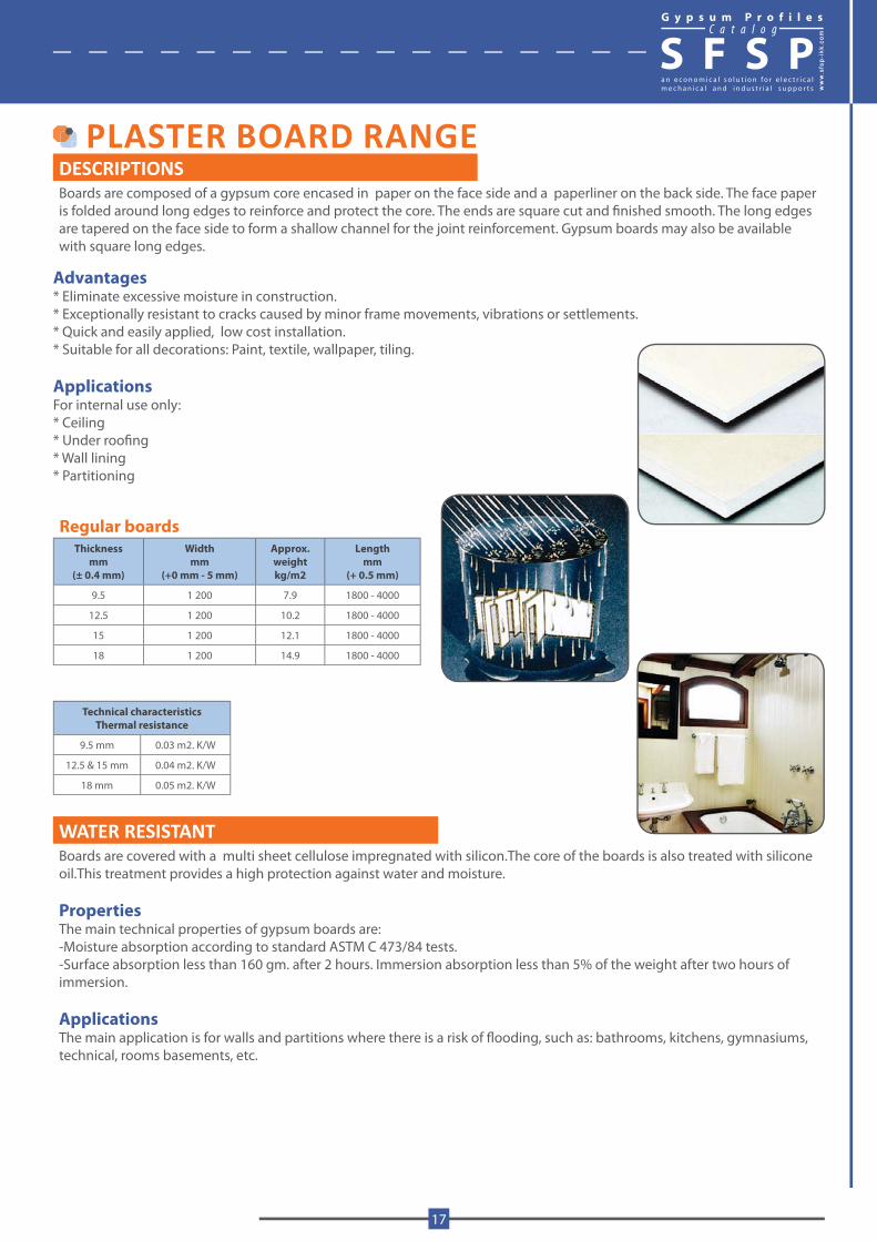
PLASTER BOARD RANGEDESCRIPTIONSBoards are composed of a gypsum core encased in paper on the face side and a paperliner on the back side. The face paper is folded around long edges to reinforce and protect the core. The ends are square cut and finished smooth. The long edges are tapered on the face side to form a shallow channel for the joint reinforcement. Gypsum boards may also be available with square long edges.
Advantages* Eliminate excessive moisture in construction.* Exceptionally resistant to cracks caused by minor frame movements, vibrations or settlements.* Quick and easily applied, low cost installation.* Suitable for all decorations: Paint, textile, wallpaper, tiling.
ApplicationsFor internal use only:* Ceiling* Under roofing* Wall lining* Partitioning
Regular boardsThickness
mm(± 0.4 mm)
Widthmm
(+0 mm - 5 mm)
Approx.weightkg/m2
Lengthmm
(+ 0.5 mm)
9.5 1 200 7.9 1800 - 4000
12.5 1 200 10.2 1800 - 4000
15 1 200 12.1 1800 - 4000
18 1 200 14.9 1800 - 4000
Technical characteristicsThermal resistance
9.5 mm 0.03 m2. K/W
12.5 & 15 mm 0.04 m2. K/W
18 mm 0.05 m2. K/W
WATER RESISTANTBoards are covered with a multi sheet cellulose impregnated with silicon.The core of the boards is also treated with silicone oil.This treatment provides a high protection against water and moisture.
PropertiesThe main technical properties of gypsum boards are:-Moisture absorption according to standard ASTM C 473/84 tests.-Surface absorption less than 160 gm. after 2 hours. Immersion absorption less than 5% of the weight after two hours of immersion.
Applications The main application is for walls and partitions where there is a risk of flooding, such as: bathrooms, kitchens, gymnasiums, technical, rooms basements, etc.
G y p s u m P r o f i l e sC a t a l o g
S F S P
www.sfs
p-ikk
.com
17
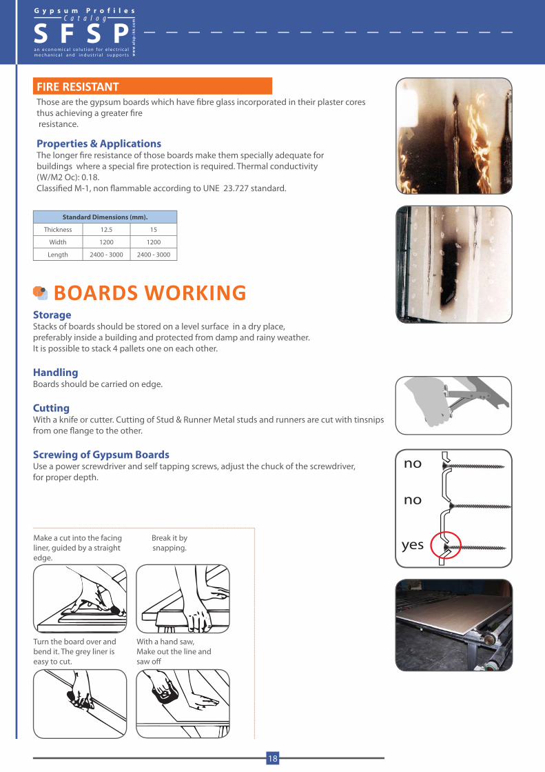
no
yes
no
Turn the board over andbend it. The grey liner iseasy to cut.
With a hand saw,Make out the line and saw off
Break it by snapping.
Make a cut into the facing liner, guided by a straight edge.
FIRE RESISTANTThose are the gypsum boards which have fibre glass incorporated in their plaster cores thus achieving a greater fire resistance.
Properties & ApplicationsThe longer fire resistance of those boards make them specially adequate forbuildings where a special fire protection is required. Thermal conductivity (W/M2 Oc): 0.18. Classified M-1, non flammable according to UNE 23.727 standard.
Standard Dimensions (mm).
Thickness 12.5 15
Width 1200 1200
Length 2400 - 3000 2400 - 3000
BOARDS WORKINGStorageStacks of boards should be stored on a level surface in a dry place, preferably inside a building and protected from damp and rainy weather.It is possible to stack 4 pallets one on each other.
HandlingBoards should be carried on edge.
CuttingWith a knife or cutter. Cutting of Stud & Runner Metal studs and runners are cut with tinsnips from one flange to the other.
Screwing of Gypsum BoardsUse a power screwdriver and self tapping screws, adjust the chuck of the screwdriver, for proper depth.
G y p s u m P r o f i l e sC a t a l o g
S F S P
18

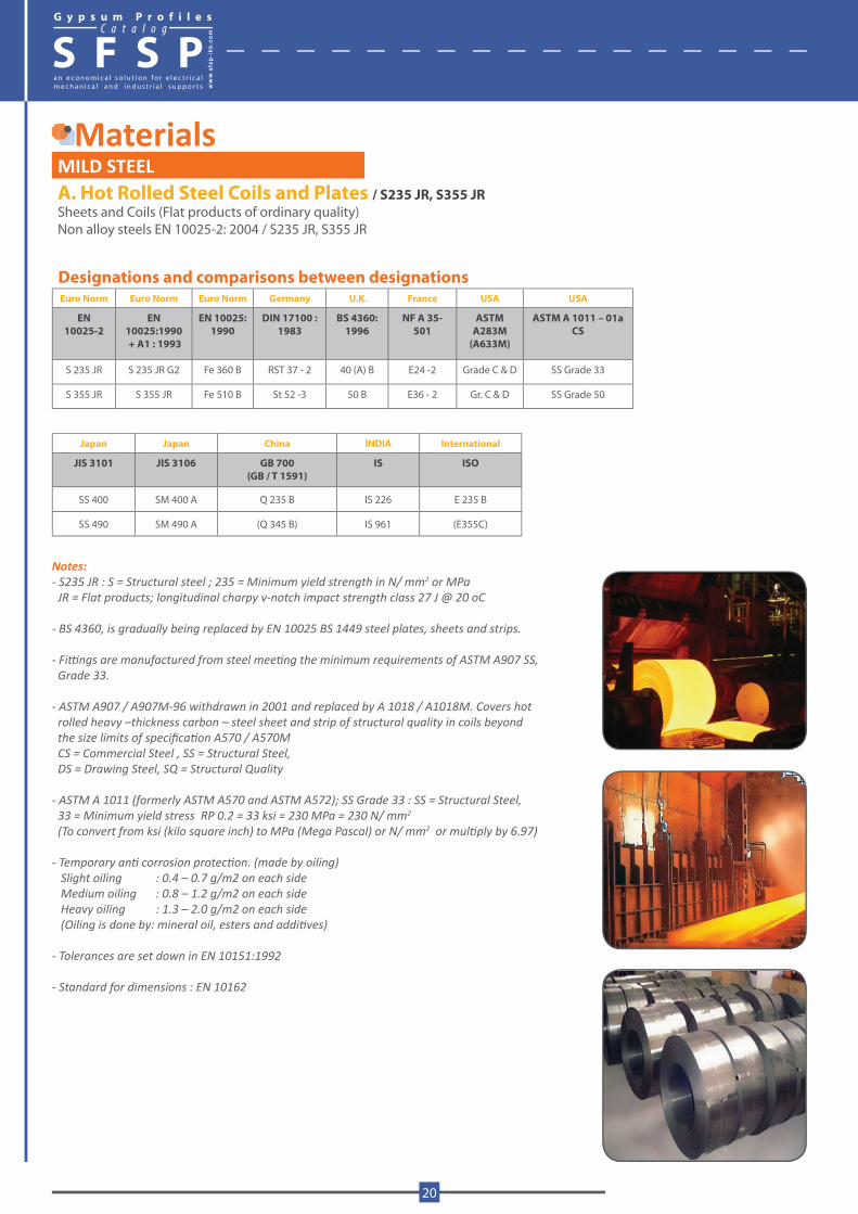
MaterialsMILD STEELA. Hot Rolled Steel Coils and Plates / S235 JR, S355 JRSheets and Coils (Flat products of ordinary quality)Non alloy steels EN 10025-2: 2004 / S235 JR, S355 JR
Designations and comparisons between designations Euro Norm Euro Norm Euro Norm Germany U.K. France USA USA
EN 10025-2
EN 10025:1990 + A1 : 1993
EN 10025: 1990
DIN 17100 :1983
BS 4360: 1996
NF A 35-501
ASTMA283M
(A633M)
ASTM A 1011 – 01aCS
S 235 JR S 235 JR G2 Fe 360 B RST 37 - 2 40 (A) B E24 -2 Grade C & D SS Grade 33
S 355 JR S 355 JR Fe 510 B St 52 -3 50 B E36 - 2 Gr. C & D SS Grade 50
Japan Japan China INDIA International
JIS 3101 JIS 3106 GB 700 (GB / T 1591)
IS ISO
SS 400 SM 400 A Q 235 B IS 226 E 235 B
SS 490 SM 490 A (Q 345 B) IS 961 (E355C)
Notes: - S235 JR : S = Structural steel ; 235 = Minimum yield strength in N/ mm2 or MPa JR = Flat products; longitudinal charpy v-notch impact strength class 27 J @ 20 oC
- BS 4360, is gradually being replaced by EN 10025 BS 1449 steel plates, sheets and strips.
- Fittings are manufactured from steel meeting the minimum requirements of ASTM A907 SS, Grade 33.
- ASTM A907 / A907M-96 withdrawn in 2001 and replaced by A 1018 / A1018M. Covers hot rolled heavy –thickness carbon – steel sheet and strip of structural quality in coils beyond the size limits of specification A570 / A570M CS = Commercial Steel , SS = Structural Steel, DS = Drawing Steel, SQ = Structural Quality
- ASTM A 1011 (formerly ASTM A570 and ASTM A572); SS Grade 33 : SS = Structural Steel, 33 = Minimum yield stress RP 0.2 = 33 ksi = 230 MPa = 230 N/ mm2
(To convert from ksi (kilo square inch) to MPa (Mega Pascal) or N/ mm2 or multiply by 6.97)
- Temporary anti corrosion protection. (made by oiling) Slight oiling : 0.4 – 0.7 g/m2 on each side Medium oiling : 0.8 – 1.2 g/m2 on each side Heavy oiling : 1.3 – 2.0 g/m2 on each side (Oiling is done by: mineral oil, esters and additives)
- Tolerances are set down in EN 10151:1992
- Standard for dimensions : EN 10162
G y p s u m P r o f i l e sC a t a l o g
S F S P
20
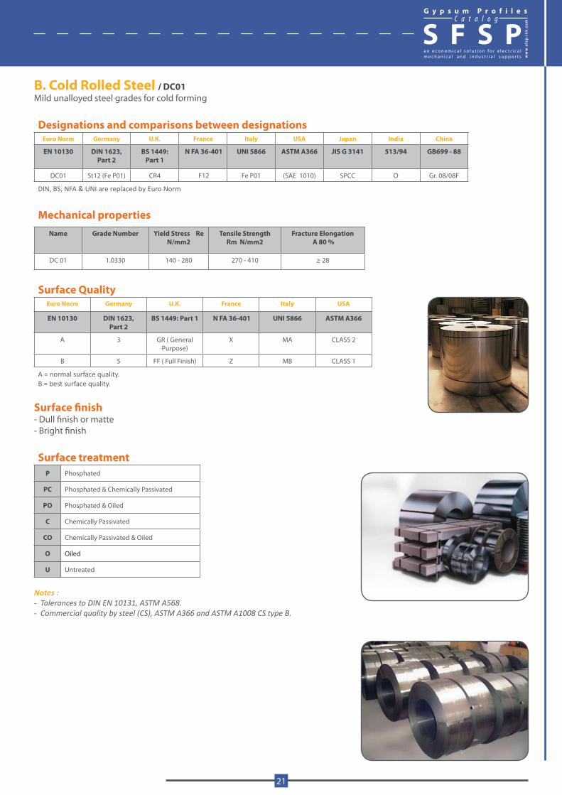
B. Cold Rolled Steel / DC01Mild unalloyed steel grades for cold forming
Designations and comparisons between designations Euro Norm Germany U.K. France Italy USA Japan India China
EN 10130 DIN 1623,Part 2
BS 1449:Part 1
N FA 36-401 UNI 5866 ASTM A366 JIS G 3141 513/94 GB699 - 88
DC01 St12 (Fe P01) CR4 F12 Fe P01 (SAE 1010) SPCC O Gr. 08/08F
DIN, BS, NFA & UNI are replaced by Euro Norm
Mechanical propertiesName Grade Number Yield Stress Re
N/mm2Tensile Strength
Rm N/mm2Fracture Elongation
A 80 %
DC 01 1.0330 140 - 280 270 - 410 ≥ 28
Surface QualityEuro Norm Germany U.K. France Italy USA
EN 10130 DIN 1623, Part 2
BS 1449: Part 1 N FA 36-401 UNI 5866 ASTM A366
A 3 GR ( General Purpose)
X MA CLASS 2
B 5 FF ( Full Finish) Z MB CLASS 1
A = normal surface quality. B = best surface quality.
Surface finish- Dull finish or matte - Bright finish
Surface treatmentP Phosphated
PC Phosphated & Chemically Passivated
PO Phosphated & Oiled
C Chemically Passivated
CO Chemically Passivated & Oiled
O Oiled
U Untreated
Notes :- Tolerances to DIN EN 10131, ASTM A568.- Commercial quality by steel (CS), ASTM A366 and ASTM A1008 CS type B.
G y p s u m P r o f i l e sC a t a l o g
S F S P
www.sfs
p-ikk
.com
21
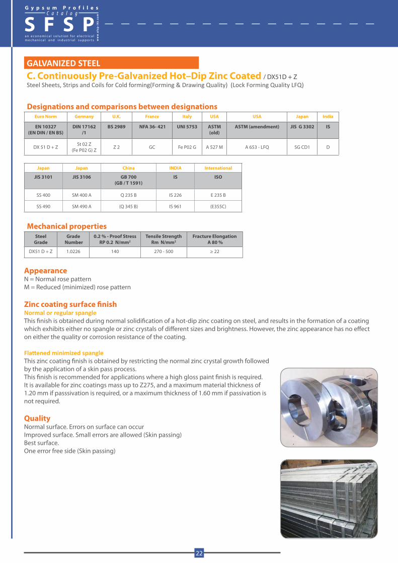
GALVANIZED STEELC. Continuously Pre-Galvanized Hot–Dip Zinc Coated / DX51D + ZSteel Sheets, Strips and Coils for Cold forming(Forming & Drawing Quality) (Lock Forming Quality LFQ)
Designations and comparisons between designations Euro Norm Germany U.K. France Italy USA USA Japan India
EN 10327(EN DIN / EN BS)
DIN 17162 /1
BS 2989 NFA 36- 421 UNI 5753 ASTM (old)
ASTM (amendment) JIS G 3302 IS
DX 51 D + Z St 02 Z (Fe P02 G) Z Z 2 GC Fe P02 G A 527 M A 653 - LFQ SG CD1 D
Japan Japan China INDIA International
JIS 3101 JIS 3106 GB 700 (GB / T 1591)
IS ISO
SS 400 SM 400 A Q 235 B IS 226 E 235 B
SS 490 SM 490 A (Q 345 B) IS 961 (E355C)
Mechanical propertiesSteel
GradeGrade
Number0.2 % - Proof Stress
RP 0.2 N/mm2Tensile Strength
Rm N/mm2Fracture Elongation
A 80 %
DX51 D + Z 1.0226 140 270 - 500 ≥ 22
AppearanceN = Normal rose patternM = Reduced (minimized) rose pattern
Zinc coating surface finishNormal or regular spangle This finish is obtained during normal solidification of a hot-dip zinc coating on steel, and results in the formation of a coating which exhibits either no spangle or zinc crystals of different sizes and brightness. However, the zinc appearance has no effect on either the quality or corrosion resistance of the coating.
Flattened minimized spangleThis zinc coating finish is obtained by restricting the normal zinc crystal growth followed by the application of a skin pass process.This finish is recommended for applications where a high gloss paint finish is required. It is available for zinc coatings mass up to Z275, and a maximum material thickness of 1.20 mm if passsivation is required, or a maximum thickness of 1.60 mm if passivation is not required.
QualityNormal surface. Errors on surface can occurImproved surface. Small errors are allowed (Skin passing)Best surface. One error free side (Skin passing)
G y p s u m P r o f i l e sC a t a l o g
S F S P
22
Coating thicknessEuro Norm Germany U.K. France Italy USA Japan
Z100 100 G100 (100 g/sqm) Z100 Z100 G40 Z 12 (120 g/sqm)
Z120 - - - - -
Z140 - - - - -
Z200 200 G200 (200 g/sqm) Z200 Z200 G60 Z 18 (180 g/sqm)
Z225 - - - - -
Z275 275 G275 (275 g/sqm) Z275 Z275 G90 Z 27 (270 g/sqm)
Z350 350 G350 (350 g/sqm) Z350 Z350 - Z 35 (350 g/sqm)
(G60 means 0.6 oz/ft2 coating thickness) (to convert from oz/ft2 to g/m2 multiply by 306)
Zink layer Surface treatmentCoating designation Minimum coating mass g/m2 Coating thickness
μm C Chemical passivation
Triple spot test Single spot test O Oil
Z100 100 85 7 CO Chemical passivation and Oil
Z120 120 90 8 U Unoiled and unpassivated
Z140 140 120 10
Z200 200 170 14
Z225 225 195 16
Z275 275 235 20
Z350 350 300 25
-The coating weight of an area of 1 m2 including both surfaces-Coating thickness (μm) is calculated from triple spot test values, and is for one side only
Notes:- DX 51D Bending and profiling quality in ASTM is CS Type B (Commercial Steel Type B)- Hot – dip galvanized steel is produced on continuous zinc coating lines from either cold rolled (thickness range 0.27 to 2.0 mm) or hot rolled (thickness range 2.01 to 3.0 mm) steel substrate; it is produced to the requirements of EN 10327, EN 10326, EN 10142, EN 10143, ASTM A 653M (Grade 33)- EN 10327 supersedes EN 10142- Hot rolled substrate Due to the nature of the hot rolling process, surface blemishes such as surface scratches and coil breaks which may be high lighted by the zinc coating, can occur on materials with a thickness of greater than 2.01 mm. Neither of these defects will affect the functionality of the materials.- Wet storage corrosion “white rust” Normally light white staining on galvanized steel is not a reason for concern. Either under a heterogeneous film of water, or under permanent condensation, white rust appears on the surface of the steel sheets. It is a precipitation of basic salts of zinc Zn (OH)2 that combines with CO2 to form a protective layer called Zinc Hydroxycarbonate.- In case of ASTM specification, the specification of hot-dip galvanized steel sheet was unified as ASTM A653. - However the former specifications likely to ASTM A526, A527, A528 are also used.- Bending Quality of EN specification is called Lock Forming Quality (LFQ) in JIS or ASTM.
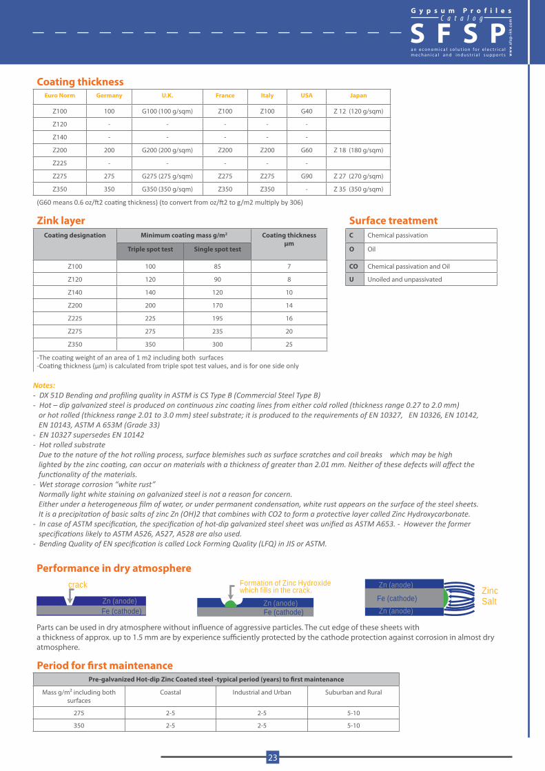
Performance in dry atmosphere
Zn (anode) Zn (anode)Fe (cathode)Fe (cathode)
Zn (anode)
Zn (anode)Fe (cathode)
crack Formation of Zinc Hydroxidewhich fills in the crack. Zinc
Salt
Parts can be used in dry atmosphere without influence of aggressive particles. The cut edge of these sheets with a thickness of approx. up to 1.5 mm are by experience sufficiently protected by the cathode protection against corrosion in almost dry atmosphere.
Period for first maintenancePre-galvanized Hot-dip Zinc Coated steel -typical period (years) to first maintenance
Mass g/m2 including both surfaces
Coastal Industrial and Urban Suburban and Rural
275 2-5 2-5 5-10
350 2-5 2-5 5-10
G y p s u m P r o f i l e sC a t a l o g
S F S P
www.sfs
p-ikk
.com
23
Surface TreatmentC Chemical passivation
O Oil
S Antifinger print (ALC – Surface)
CO Chemical passivatin and Oil
Appearance M = Normal rose pattern
Quality A- Normal surface. Errors on surface can occur B- Improved surface. Small errors are allowed
D. Electro Galvanized Steel (Electrolytic Coating) / DC01 + ZEThe base material for electrolyticaly coated steel is cold-rolled, annealed, lightly temper – rolled strip
Designations and comparisons between designations Euro Norm Euro Norm Germany U.K. France Italy USA Japan Japan
EN 10152 EN 10152 - 92 DIN 17163-88 BS 1449 /1 NF 36-401 UNI 5866 ASTM A146 JIS G 3313 JIS G 3141
DC 01 + ZE Fe P01 ZE St 12 ZE CR 4 C Fe P01 A591 - CQ SECC SPCC
Mechanical propertiesName Grade Number Yield Stress Tensile Strength Elongation
Re N/mm2 Rm N/mm2 A80 %
DC 01 + ZE 1.0330 140 - 280 270 - 410 ≥ 28
Coating thickness (EG)Coating
Designa-tion*
Nominal Zinc coating values
for each surface
Minimum Zinc coating values
for each surface
Marking
Thickness Mass Thickness Mass
μm g / m2 μm g / m2
ZE 25 / 25 2.5 18 1.7 12 E16 ZE 25/25
ZE 30 / 30 5.0 36 4.1 29 E24 ZE 50/50
ZE 50 / 50 7.5 54 6.6 47 E40 ZE 75/75
ZE 100 / 100 10.0 72 9.1 65 ZE 100/100
(to convert from g /m2 to oz / ft2 multiply by 0.00327)*After BSEN 10152:1994
Surface treatmentP Phosphated
PC Phosphated & Chemically Passivated
PO Phosphated & Oiled
C Chemically Passivated
CO Chemically Passivated & Oiled
O Oiled
U Untreated
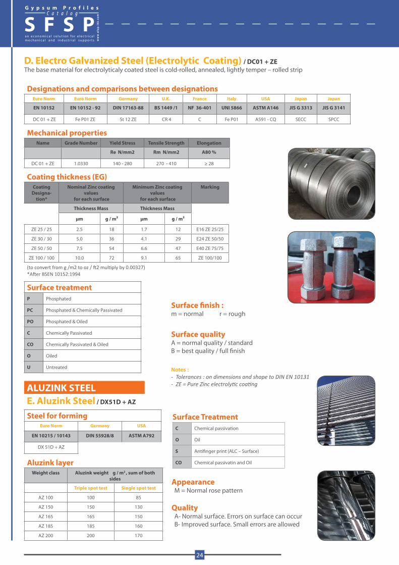
ALUZINK STEELE. Aluzink Steel / DX51D + AZ
Steel for forming Euro Norm Germany USA
EN 10215 / 10143 DIN 55928/8 ASTM A792
DX 51D + AZ
Aluzink layerWeight class Aluzink weight g / m2 , sum of both
sides
Triple spot test Single spot test
AZ 100 100 85
AZ 150 150 130
AZ 165 165 150
AZ 185 185 160
AZ 200 200 170
Surface finish :m = normal r = rough
Surface qualityA = normal quality / standardB = best quality / full finish
Notes : - Tolerances : on dimensions and shape to DIN EN 10131- ZE = Pure Zinc electrolytic coating
G y p s u m P r o f i l e sC a t a l o g
S F S P
24
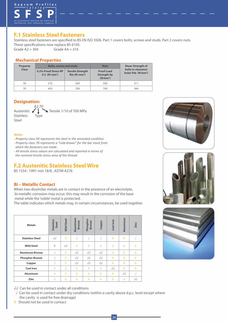
1200
1000
800
600
400
200
0 00 20
20
40
40
60
60
Ultimate TensileStrength
0.2% ProofStrength
Elongation
Elon
gatio
n %
Stre
ngth
N/m
m2
Effect of cold working in grade 304 Stainless Steel
Stre
ss
0.2% Proof Stress (Rp)
Strain0.2% Plastic Strain
Typical Stress/Strain Curve for Stainless Steel
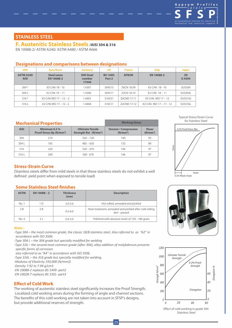
STAINLESS STEEL F. Austenitic Stainless Steels /AISI 304 & 316EN 10088-2/ ASTM A240/ ASTM A480 / ASTM A666
Designations and comparisons between designations USA Euro Norm Germany UK France Italy Japan
ASTM A240AISI
Steel nameEN 10088-2
DIN Steel number17440
BS 1449:Part 2
AFNOR EN 10088-2 JISG 4304
304 * X5 CrNi 18 - 10 1.4301 304S15 Z6CN 18.09 X5 CrNi 18 - 10 SUS304
304 L X2 CrNi 19 – 11 1.4306 304S11 Z2CN 18.10 X2 CrNi 18 – 11 SUS304L
316 * X5 CrNi MO 17 – 12 – 2 1.4401 316S31 Z6CND 17.11 X5 CrNi MO 17 – 12 (SUS316)
316 L X2 CrNi MO 17 – 12 - 2 1.4404 316S11 Z2CND 17.12 X2 CrNi MO 17 – 17 - 12 SUS316L
Mechanical Properties Working Stress
AISI Minimum 0.2 % Proof Stress Rp (N/mm2)
Ultimate Tensile Strength Rm (N/mm2)
Tension / Compression (N/mm2)
Shear (N/mm2)
304 210 520 – 720 140 93
304 L 185 485 – 650 133 89
316 220 520 – 670 146 97
316 L 200 500 - 670 146 97
Stress-Strain Curve(Stainless steels differ from mild steels in that these stainless steels do not exhibit a welldefined yield point when exposed to tensile load)
Some Stainless Steel finishesASTM EN 10088 – 2 Thickness
(mm)Description
No. 1 1 D 3.0-5.0 Hot rolled, annealed and pickled
2 B 2 B0.3-6.0
Heat treatment, annealed and pickled after cold rolling skin - passed
No. 4 2 J 0.4-3.0 Polished with abrasive mesh of 150 - 180 grain
Notes : -Type 304 – the most common grade; the classic 18/8 stainless steel. Also referred to as “A2” in accordance with ISO 3506.-Type 304 L – the 304 grade but specially modified for welding-Type 316 – the second most common grade (after 304), alloy addition of molybdenum prevents specific forms of corrosion. also referred to as “A4” in accordance with ISO 3506.-Type 316L – the 316 grade but specially modified for welding.-Modulus of Elasticity 193,000 (N/mm2)-Density 7.92 to 7.94 g/cm3-EN 10088-2 replaces BS 1449- part2-EN 10028-7 replaces BS 1501- part3
Effect of Cold WorkThe working of austenitic stainless steel significantly increases the Proof Strength. Localized cold working arises during the forming of angle and channel sections.The benefits of this cold working are not taken into account in SFSP’s designs, but provide additional reserves of strength.
G y p s u m P r o f i l e sC a t a l o g
S F S P
www.sfs
p-ikk
.com
25
F.1 Stainless Steel FastenersStainless steel fasteners are specified to BS EN ISO 3506. Part 1 covers bolts, screws and studs. Part 2 covers nuts. These specifications now replace BS 6105.Grade A2 = 304 Grade A4 = 316
Mechanical PropertiesProperty
ClassBolts, screws and studs Nuts Shear Strength of
bolts in clearance holes Psb (N/mm2)0.2% Proof Stress RP
0.2 (N/ mm2)Tensile Strength
Rm (N/ mm2)Proof Load
Strength Sp (N/mm2)
50 210 500 500 311
70 450 700 700 384
Designation: A2 70Austenitic Tensile 1/10 of 700 MPaStainless TypeSteel
Notes:- Property class 50 represents the steel in the annealed condition- Property class 70 represents a “cold drawn” for the bar stock from which the fasteners are made.- All tensile stress values are calculated and reported in terms of the nominal tensile stress area of the thread.
F.2 Austenitic Stainless Steel WireBS 1554 : 1991 min 18/8 , ASTM A276
Bi – Metallic ContactWhen two dissimilar metals are in contact in the presence of an electrolyte, bi-metallic corrosion may occur, this may result in the corrosion of the base metal while the ‘noble’ metal is protected.The table indicates which metals may, in certain circumstances, be used together.
Metals
Stai
nles
s St
eel
Mild
Ste
el
Alu
min
ium
Br
onze
Phos
phor
Br
onze
Copp
er
Cast
Iron
Alu
min
ium
Zinc
Stainless Steel √√ X √ √ √ X X √
Mild Steel X √√ X X X √ X X
Aluminum Bronze √ X √√ √√ √√ X X X
Phosphor Bronze √ X √√ √√ √√ X X X
Copper √ X √√ √√ √√ X X X
Cast Iron X √ X X X √√ X X
Aluminum X X X X X X √√ √
Zinc √ X X X X X √ √√
√√ Can be used in contact under all conditions √ Can be used in contact under dry conditions (within a cavity above d.p.c. level except where the cavity is used for free drainage)X Should not be used in contact
G y p s u m P r o f i l e sC a t a l o g
S F S P
26
ALUMINIUM
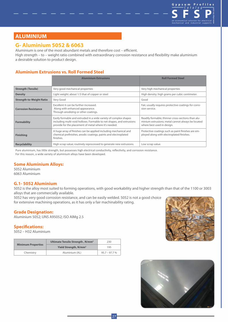
G- Aluminium 5052 & 6063Aluminium is one of the most abundant metals and therefore cost – efficient. High strength – to – weight ratio combined with extraordinary corrosion resistance and flexibility make aluminium a desirable solution to product design.
Aluminium Extrusions vs. Roll Formed SteelAluminium Extrusions Roll Formed Steel
Strength (Tensile) Very good mechanical properties Very high mechanical properties
Density Light weight: about 1/3 that of copper or steel High density; high grams per cubic centimeter.
Strength-to-Weight Ratio Very Good Good
Corrosion ResistanceExcellent it can be further increased. Along with enhanced appearance.Through anodizing or other coatings.
Fair, usually requires protective coatings for corro-sion service.
FormabilityEasily formable and extruded in a wide variety of complex shapes including multi-void hollows. Formable to net shapes, and extrusions provide for the placement of metal where it’s needed.
Readily formable; thinner cross-sections than alu-minium extrusions; metal cannot always be located where best used in design.
FinishingA huge array of finishes can be applied including mechanical and chemical prefinishes, anodic coatings, paints and electroplated finishes.
Protective coatings such as paint finishes are em-ployed along with electroplated finishes.
Recyclability High scrap value; routinely reprocessed to generate new extrusions. Low scrap value.
Pure aluminium, has little strength, but possesses high electrical conductivity, reflectivity, and corrosion resistance. For this reason, a wide variety of aluminium alloys have been developed.
Some Aluminium Alloys:5052 Aluminium 6063 Aluminium
G.1- 5052 Aluminium 5052 is the alloy most suited to forming operations, with good workability and higher strength than that of the 1100 or 3003 alloys that are commercially available.5052 has very good corrosion resistance, and can be easily welded. 5052 is not a good choice for extensive machining operations, as it has only a fair machinability rating.
Grade Designation: Aluminium 5052; UNS A95052; ISO AlMg 2.5 Specifications:5052 – H32 Aluminium
Minimum PropertiesUltimate Tensile Strength , N/mm2 230
Yield Strength, N/mm2 195
Chemistry Aluminium (AL) 95.7 – 97.7 %
G y p s u m P r o f i l e sC a t a l o g
S F S P
www.sfs
p-ikk
.com
27

G.2-6063 Aluminium 6063 is often called architectural aluminium for two reasons – first, it has a surface finish that is far smoother than the other commercially available alloys, and second, its strength is significantly less (roughly half the strength of 6061), making it suited for applications where strength is not the foremost consideration.6063 is rated “Good” for forming and cold working operations, “Excellent” for anodizing, and “Fair” for machining.
Grade Designation:- Aluminium 6063-T6; UNS A96063; ISO AlMg 0.5Si;Also corresponds to the following standard designations and specifications:
AA6063 ASTM B361
GS10 ASTM B483
A-GS MIL G – 18014
ASTM B210 MIL P – 25995
ASTM B241 QQ A – 200 / 9
United Kingdom BS H19; DTD 372B
Germany DIN AlMg Si 0.5Werkstoff – Nr : 3.3206
Mechanical Properties 6063 – T6 6063 – T52
Ultimate Tensile Strength N/mm2Tensile Yield Strength
N/mm2
240215
185145
Modulus of Elasticity N/mm2Elongation at Break %Fatigue Strength N/mm2
68,90012
68.9
68,90012
68.9
Machinability %Shear Modulus N/mm2 Shear Strength N/mm2
5025,800
150
----- ----- -----
Density g/cm3 Aluminium (Al) Content %
2.797.5
2.797.5
Conversion From To Multiply by
MPa N/mm2 1
GPa N/mm2 1000
N/mm2 psi 145
GPa ksi 145
MPa psi 145
ksi psi 1000
lb/in3 g/cm3 27.7
Surface FinishNatural metallic finish
G y p s u m P r o f i l e sC a t a l o g
S F S P
28

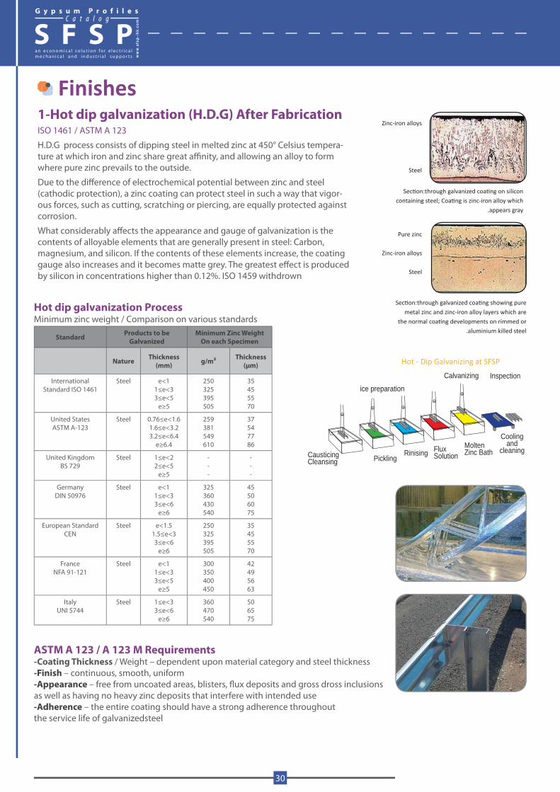
Finishes1-Hot dip galvanization (H.D.G) After FabricationISO 1461 / ASTM A 123
H.D.G process consists of dipping steel in melted zinc at 450° Celsius tempera-ture at which iron and zinc share great affinity, and allowing an alloy to form where pure zinc prevails to the outside.
Due to the difference of electrochemical potential between zinc and steel (cathodic protection), a zinc coating can protect steel in such a way that vigor-ous forces, such as cutting, scratching or piercing, are equally protected against corrosion.
What considerably affects the appearance and gauge of galvanization is the contents of alloyable elements that are generally present in steel: Carbon, magnesium, and silicon. If the contents of these elements increase, the coating gauge also increases and it becomes matte grey. The greatest effect is produced by silicon in concentrations higher than 0.12%. ISO 1459 withdrown
Hot dip galvanization ProcessMinimum zinc weight / Comparison on various standards
Standard Products to be Galvanized
Minimum Zinc WeightOn each Specimen
Nature Thickness (mm) g/m2 Thickness
(μm)
International Standard ISO 1461
Steel e<11≤e<33≤e<5
e≥5
250325395505
35455570
United States ASTM A-123
Steel 0.76≤e<1.61.6≤e<3.23.2≤e<6.4
e≥6.4
259381549610
37547786
United KingdomBS 729
Steel 1≤e<22≤e<5
e≥5
---
---
Germany DIN 50976
Steel e<11≤e<33≤e<6
e≥6
325360430540
45506075
European StandardCEN
Steel e<1.51.5≤e<33≤e<6
e≥6
250325395505
35455570
France NFA 91-121
Steel e<11≤e<33≤e<5
e≥5
300350400450
42495663
Italy UNI 5744
Steel 1≤e<33≤e<6
e≥6
360470540
506575
ASTM A 123 / A 123 M Requirements-Coating Thickness / Weight – dependent upon material category and steel thickness -Finish – continuous, smooth, uniform -Appearance – free from uncoated areas, blisters, flux deposits and gross dross inclusions as well as having no heavy zinc deposits that interfere with intended use -Adherence – the entire coating should have a strong adherence throughout the service life of galvanizedsteel
Section:through galvanized coating showing pure metal zinc and zinc-iron alloy layers which are
the normal coating developments on rimmed or.aluminium killed steel
Section:through galvanized coating on silicon containing steel; Coating is zinc-iron alloy which
.appears gray
Zinc-iron alloys
Steel
Pure zinc
Zinc-iron alloys
Steel
ice preparation
Calvanizing Inspection
Coolingand
cleaningMoltenZinc BathFlux
SolutionRinisingPicklingCausticing
Cleansing
Hot - Dip Galvanizing at SFSP
G y p s u m P r o f i l e sC a t a l o g
S F S P
30
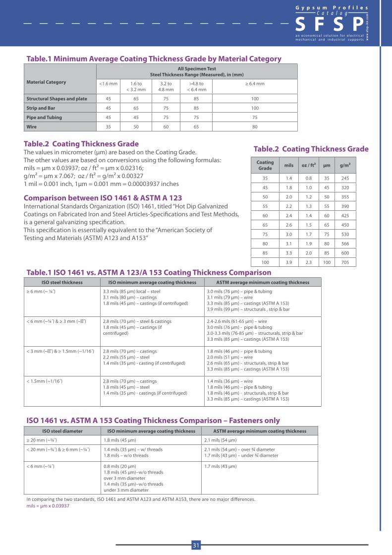
Table.1 Minimum Average Coating Thickness Grade by Material Category
Material Category
All Specimen TestSteel Thickness Range (Measured), in (mm)
<1.6 mm 1.6 to < 3.2 mm
3.2 to 4.8 mm
>4.8 to < 6.4 mm
≥ 6.4 mm
Structural Shapes and plate 45 65 75 85 100
Strip and Bar 45 65 75 85 100
Pipe and Tubing 45 45 75 75 75
Wire 35 50 60 65 80
Table.2 Coating Thickness GradeThe values in micrometer (μm) are based on the Coating Grade. The other values are based on conversions using the following formulas:mils = μm x 0.03937; oz / ft2 = μm x 0.02316; g/m2 = μm x 7.067; oz / ft2 = g/m2 x 0.00327 1 mil = 0.001 inch, 1μm = 0.001 mm = 0.00003937 inches
Comparison between ISO 1461 & ASTM A 123International Standards Organization (ISO) 1461, titled “Hot Dip Galvanized Coatings on Fabricated Iron and Steel Articles-Specifications and Test Methods,is a general galvanizing specification.This specification is essentially equivalent to the “American Society of Testing and Materials (ASTM) A123 and A153”
Table.1 ISO 1461 vs. ASTM A 123/A 153 Coating Thickness ComparisonISO steel thickness ISO minimum average coating thickness ASTM average minimum coating thickness
≥ 6 mm (~ ¼˝) 3.3 mils (85 μm) local – steel3.1 mils (80 μm) – castings1.8 mils (45 μm) – castings (if centrifuged)
3.0 mils (76 μm) – pipe & tubing3.1 mils (79 μm) – wire3.3 mils (85 μm) – castings (ASTM A 153)3.9 mils (99 μm) – structurals , strip & bar
< 6 mm (~¼˝) & ≥ 3 mm (~�˝) 2.8 mils (70 μm) – steel & castings1.8 mils (45 μm) – castings (if centrifuged)
2.4-2.6 mils (61-65 μm) – wire3.0 mils (76 μm) - pipe & tubing 3.0-3.3 mils (76-85 μm) – structurals, strip & bar3.3 mils (85 μm) – castings (ASTM A 153)
< 3 mm (~�˝) & ≥ 1.5mm (~1/16˝) 2.8 mils (70 μm) – castings2.2 mils (55 μm) – steel1.4 mils (35 μm) - casting (if centrifuged)
1.8 mils (46 μm) – pipe & tubing2.0 mils (51 μm) – wire2.6 mils (65 μm) - structurals, strip & bar3.3 mils (85 μm) – castings (ASTM A 153)
< 1.5mm (~1/16˝) 2.8 mils (70 μm) – castings1.8 mils (45 μm) – steel1.4 mils (35 μm) - castings (if centrifuged)
1.4 mils (36 μm) – wire1.8 mils (46 μm) – pipe & tubing1.8 mils (46 μm) - structurals, strip & bar3.3 mils (85 μm) – castings (ASTM A 153)
ISO 1461 vs. ASTM A 153 Coating Thickness Comparison – Fasteners only ISO steel diameter ISO minimum average coating thickness ASTM average minimum coating thickness
≥ 20 mm (~¾˝) 1.8 mils (45 μm) 2.1 mils (54 μm)
< 20 mm (~¾˝) & ≥ 6 mm (~¼˝) 1.4 mils (35 μm) – w/ threads1.8 mils – w/o threads
2.1 mils (54 μm) – over ¾̋ diameter1.7 mils (43 μm) – under ¾̋ diameter
< 6 mm (~¼˝) 0.8 mils (20 μm)1.8 mils (45 μm)–w/o threadsover 3 mm diameter1.4 mils (35 μm)–w/o threadsunder 3 mm diameter
1.7 mils (43 μm)
In comparing the two standards, ISO 1461 and ASTM A123 and ASTM A153, there are no major differences.mils = μm x 0.03937
Table.2 Coating Thickness Grade
Coating Grade mils oz / ft2 μm g/m2
35 1.4 0.8 35 245
45 1.8 1.0 45 320
50 2.0 1.2 50 355
55 2.2 1.3 55 390
60 2.4 1.4 60 425
65 2.6 1.5 65 450
75 3.0 1.7 75 530
80 3.1 1.9 80 566
85 3.3 2.0 85 600
100 3.9 2.3 100 705
G y p s u m P r o f i l e sC a t a l o g
S F S P
www.sfs
p-ikk
.com
31
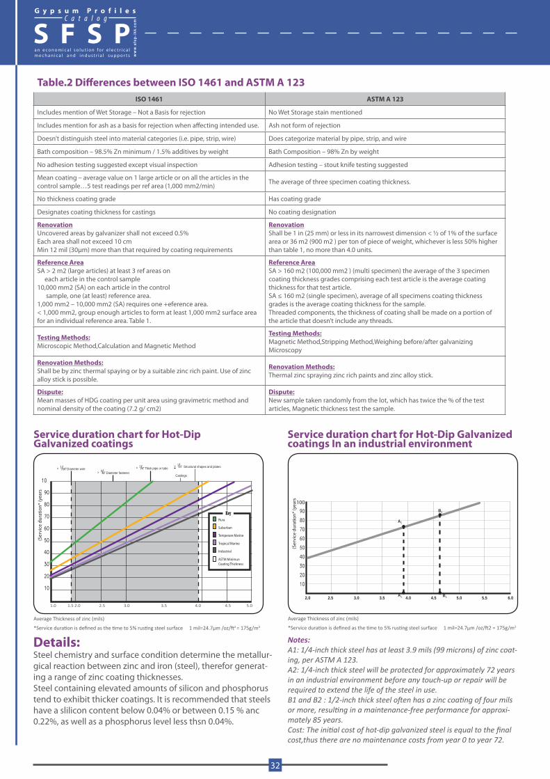
Table.2 Differences between ISO 1461 and ASTM A 123ISO 1461 ASTM A 123
Includes mention of Wet Storage – Not a Basis for rejection No Wet Storage stain mentioned
Includes mention for ash as a basis for rejection when affecting intended use. Ash not form of rejection
Doesn’t distinguish steel into material categories (i.e. pipe, strip, wire) Does categorize material by pipe, strip, and wire
Bath composition – 98.5% Zn minimum / 1.5% additives by weight Bath Composition – 98% Zn by weight
No adhesion testing suggested except visual inspection Adhesion testing – stout knife testing suggested
Mean coating – average value on 1 large article or on all the articles in the control sample…5 test readings per ref area (1,000 mm2/min) The average of three specimen coating thickness.
No thickness coating grade Has coating grade
Designates coating thickness for castings No coating designation
RenovationUncovered areas by galvanizer shall not exceed 0.5%Each area shall not exceed 10 cmMin 12 mil (30μm) more than that required by coating requirements
RenovationShall be 1 in (25 mm) or less in its narrowest dimension < ½ of 1% of the surface area or 36 m2 (900 m2 ) per ton of piece of weight, whichever is less 50% higher than table 1, no more than 4.0 units.
Reference AreaSA > 2 m2 (large articles) at least 3 ref areas on each article in the control sample10,000 mm2 (SA) on each article in the control sample, one (at least) reference area.1,000 mm2 – 10,000 mm2 (SA) requires one +eference area.< 1,000 mm2, group enough articles to form at least 1,000 mm2 surface area for an individual reference area. Table 1.
Reference AreaSA > 160 m2 (100,000 mm2 ) (multi specimen) the average of the 3 specimen coating thickness grades comprising each test article is the average coating thickness for that test article.SA ≤ 160 m2 (single specimen), average of all specimens coating thickness grades is the average coating thickness for the sample.Threaded components, the thickness of coating shall be made on a portion of the article that doesn’t include any threads.
Testing Methods:Microscopic Method,Calculation and Magnetic Method
Testing Methods:Magnetic Method,Stripping Method,Weighing before/after galvanizingMicroscopy
Renovation Methods:Shall be by zinc thermal spaying or by a suitable zinc rich paint. Use of zinc alloy stick is possible.
Renovation Methods:Thermal zinc spraying zinc rich paints and zinc alloy stick.
Dispute:Mean masses of HDG coating per unit area using gravimetric method and nominal density of the coating (7.2 g/ cm2)
Dispute:New sample taken randomly from the lot, which has twice the % of the test articles, Magnetic thickness test the sample.
Details:Steel chemistry and surface condition determine the metallur-gical reaction between zinc and iron (steel), therefor generat-ing a range of zinc coating thicknesses.Steel containing elevated amounts of silicon and phosphorus tend to exhibit thicker coatings. It is recommended that steels have a slilicon content below 0.04% or between 0.15 % anc 0.22%, as well as a phosphorus level less thsn 0.04%.
Notes:A1: 1/4-inch thick steel has at least 3.9 mils (99 microns) of zinc coat-ing, per ASTM A 123.A2: 1/4-inch thick steel will be protected for approximately 72 years in an industrial environment before any touch-up or repair will be required to extend the life of the steel in use.B1 and B2 : 1/2-inch thick steel often has a zinc coating of four mils or more, resulting in a maintenance-free performance for approxi-mately 85 years.Cost: The initial cost of hot-dip galvanized steel is equal to the final cost,thus there are no maintenance costs from year 0 to year 72.
Service duration chart for Hot-Dip Galvanized coatings In an industrial environment
Average Thickness of zinc (mils)
*Service duration is defined as the time to 5% rusting steel surface 1 mil=24.7μm /oz/ft2 = 175g/m2
90
80
70
60
50
40
30
20
10
A2
A1 B1
B2
2.0 2.5 3.0 4.0 5.0 6.03.5 4.5 5.5
100
(Ser
vice
dur
atio
n* (y
ears
Average Thickness of zinc (mils)
*Service duration is defined as the time to 5% rusting steel surface 1 mil=24.7μm /oz/ft2 = 175g/m2
Service duration chart for Hot-Dip Galvanized coatings
(Ser
vice
dur
atio
n* (y
ears
KeyRura
Suburban
Temperare Marine
Tropical Marine
Industrial
ASTM MinimunCoating Thickness
10
90
80
70
60
50
40
30
20
10
< 1/16’’ Diameter wire> 3/8’’ Diameter fastener
> 1/4’’ Thick pipe or tube > 1/4’’ Structural shapes and plates
Castings
1.0 1.5 2.0 2.5 3.0 3.5 4.0 4.5 5.0
G y p s u m P r o f i l e sC a t a l o g
S F S P
32
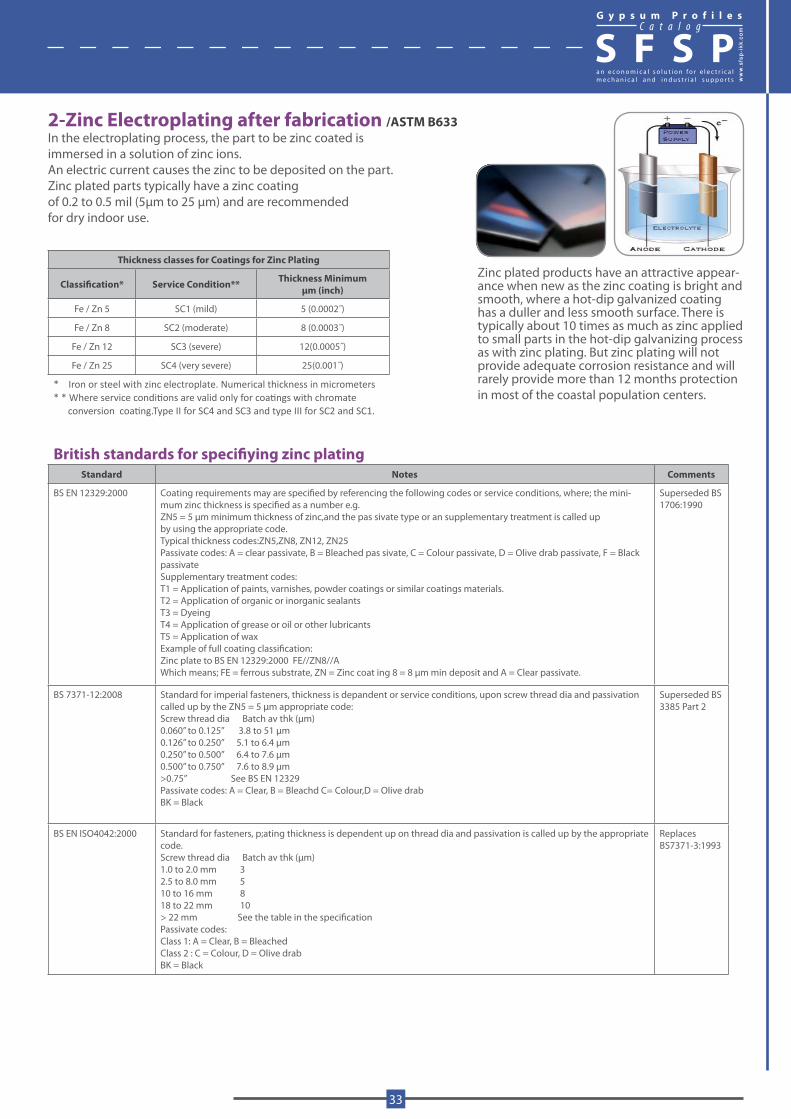
2-Zinc Electroplating after fabrication /ASTM B633In the electroplating process, the part to be zinc coated isimmersed in a solution of zinc ions. An electric current causes the zinc to be deposited on the part.Zinc plated parts typically have a zinc coating of 0.2 to 0.5 mil (5μm to 25 μm) and are recommended for dry indoor use.
Thickness classes for Coatings for Zinc Plating
Classification* Service Condition** Thickness Minimum μm (inch)
Fe / Zn 5 SC1 (mild) 5 (0.0002˝)
Fe / Zn 8 SC2 (moderate) 8 (0.0003˝)
Fe / Zn 12 SC3 (severe) 12(0.0005˝)
Fe / Zn 25 SC4 (very severe) 25(0.001˝)
* Iron or steel with zinc electroplate. Numerical thickness in micrometers* * Where service conditions are valid only for coatings with chromate conversion coating.Type II for SC4 and SC3 and type III for SC2 and SC1.
British standards for specifiying zinc platingStandard Notes Comments
BS EN 12329:2000 Coating requirements may are specified by referencing the following codes or service conditions, where; the mini-mum zinc thickness is specified as a number e.g.ZN5 = 5 μm minimum thickness of zinc,and the pas sivate type or an supplementary treatment is called upby using the appropriate code.Typical thickness codes:ZN5,ZN8, ZN12, ZN25Passivate codes: A = clear passivate, B = Bleached pas sivate, C = Colour passivate, D = Olive drab passivate, F = Black passivateSupplementary treatment codes:T1 = Application of paints, varnishes, powder coatings or similar coatings materials.T2 = Application of organic or inorganic sealantsT3 = DyeingT4 = Application of grease or oil or other lubricantsT5 = Application of waxExample of full coating classification:Zinc plate to BS EN 12329:2000 FE//ZN8//AWhich means; FE = ferrous substrate, ZN = Zinc coat ing 8 = 8 μm min deposit and A = Clear passivate.
Superseded BS 1706:1990
BS 7371-12:2008 Standard for imperial fasteners, thickness is depandent or service conditions, upon screw thread dia and passivation called up by the ZN5 = 5 μm appropriate code:Screw thread dia Batch av thk (μm)0.060’’ to 0.125’’ 3.8 to 51 μm0.126’’ to 0.250’’ 5.1 to 6.4 μm0.250’’ to 0.500’’ 6.4 to 7.6 μm0.500’’ to 0.750’’ 7.6 to 8.9 μm>0.75’’ See BS EN 12329Passivate codes: A = Clear, B = Bleachd C= Colour,D = Olive drab BK = Black
Superseded BS 3385 Part 2
BS EN ISO4042:2000 Standard for fasteners, p;ating thickness is dependent up on thread dia and passivation is called up by the appropriate code.Screw thread dia Batch av thk (μm)1.0 to 2.0 mm 32.5 to 8.0 mm 510 to 16 mm 818 to 22 mm 10> 22 mm See the table in the specificationPassivate codes:Class 1: A = Clear, B = BleachedClass 2 : C = Colour, D = Olive drabBK = Black
Replaces BS7371-3:1993
Zinc plated products have an attractive appear-ance when new as the zinc coating is bright and smooth, where a hot-dip galvanized coating has a duller and less smooth surface. There is typically about 10 times as much as zinc applied to small parts in the hot-dip galvanizing process as with zinc plating. But zinc plating will not provide adequate corrosion resistance and will rarely provide more than 12 months protection in most of the coastal population centers.
G y p s u m P r o f i l e sC a t a l o g
S F S P
www.sfs
p-ikk
.com
33
Standards Thickness
BS EN 12329:2000 FE / ZN SA 5 μm
BS EN 12329:2000 FE / ZN 12A & 12/C 12 μm
BS 1706 FE ZN 8c2c 8 μm
BS 1706 FE ZN 5c2c 5 μm
BS 3382 parts 1&2 1961 10 μm
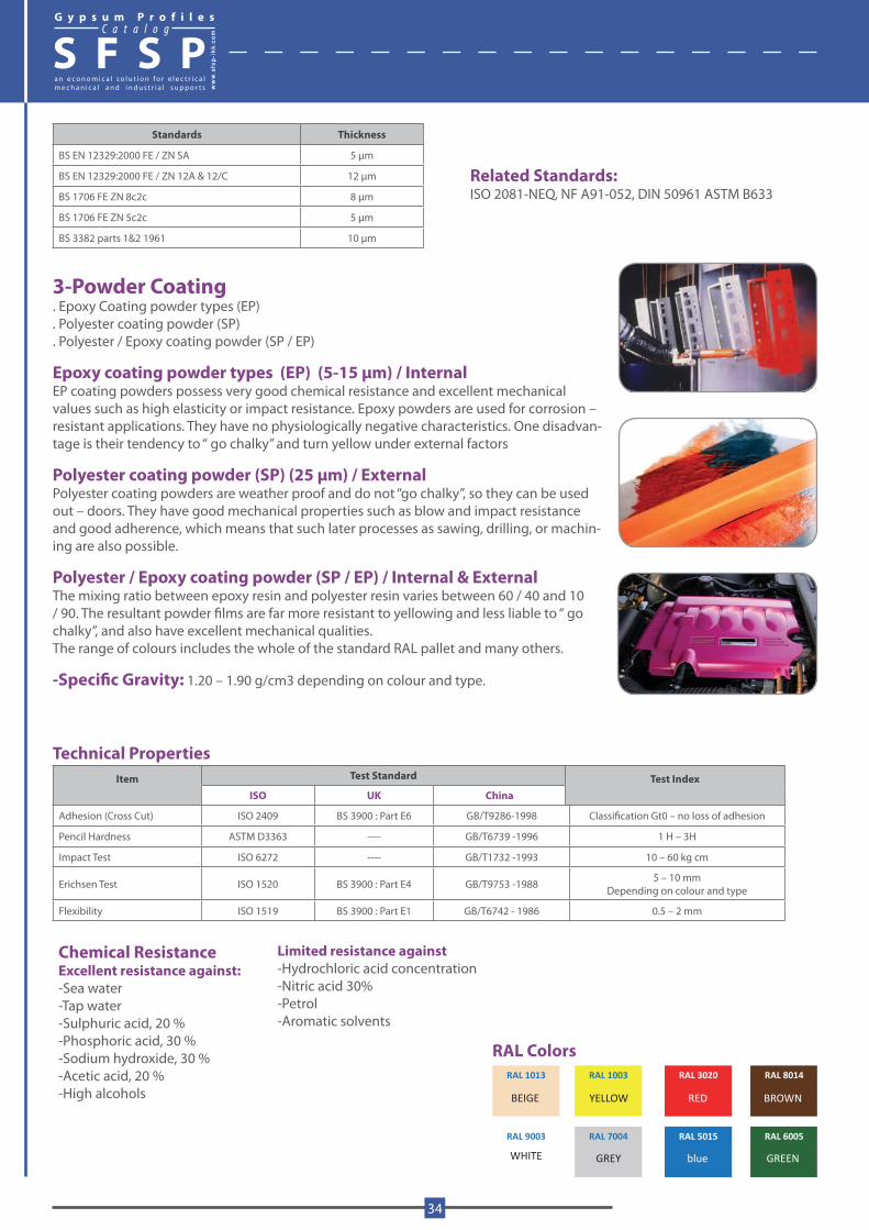
3-Powder Coating. Epoxy Coating powder types (EP). Polyester coating powder (SP). Polyester / Epoxy coating powder (SP / EP)
Epoxy coating powder types (EP) (5-15 μm) / InternalEP coating powders possess very good chemical resistance and excellent mechanical values such as high elasticity or impact resistance. Epoxy powders are used for corrosion – resistant applications. They have no physiologically negative characteristics. One disadvan-tage is their tendency to “ go chalky” and turn yellow under external factors
Polyester coating powder (SP) (25 μm) / ExternalPolyester coating powders are weather proof and do not “go chalky”, so they can be used out – doors. They have good mechanical properties such as blow and impact resistance and good adherence, which means that such later processes as sawing, drilling, or machin-ing are also possible.
Polyester / Epoxy coating powder (SP / EP) / Internal & ExternalThe mixing ratio between epoxy resin and polyester resin varies between 60 / 40 and 10 / 90. The resultant powder films are far more resistant to yellowing and less liable to “ go chalky”, and also have excellent mechanical qualities.The range of colours includes the whole of the standard RAL pallet and many others.
-Specific Gravity: 1.20 – 1.90 g/cm3 depending on colour and type.
Technical Properties Item Test Standard Test Index
ISO UK China
Adhesion (Cross Cut) ISO 2409 BS 3900 : Part E6 GB/T9286-1998 Classification Gt0 – no loss of adhesion
Pencil Hardness ASTM D3363 ---- GB/T6739 -1996 1 H – 3H
Impact Test ISO 6272 ---- GB/T1732 -1993 10 – 60 kg cm
Erichsen Test ISO 1520 BS 3900 : Part E4 GB/T9753 -1988 5 – 10 mm Depending on colour and type
Flexibility ISO 1519 BS 3900 : Part E1 GB/T6742 - 1986 0.5 – 2 mm
Chemical ResistanceExcellent resistance against:-Sea water -Tap water-Sulphuric acid, 20 %-Phosphoric acid, 30 %-Sodium hydroxide, 30 %-Acetic acid, 20 %-High alcohols
Limited resistance against-Hydrochloric acid concentration-Nitric acid 30%-Petrol-Aromatic solvents
Related Standards:ISO 2081-NEQ, NF A91-052, DIN 50961 ASTM B633
RAL 1013
RAL 1003
RAL 3020
RAL 8014
RAL 9003
RAL 7004
RAL 5015
RAL 6005
GREENblue
YELLOW BROWNREDBEIGE
GREYWHITE
RAL Colors
G y p s u m P r o f i l e sC a t a l o g
S F S P
34
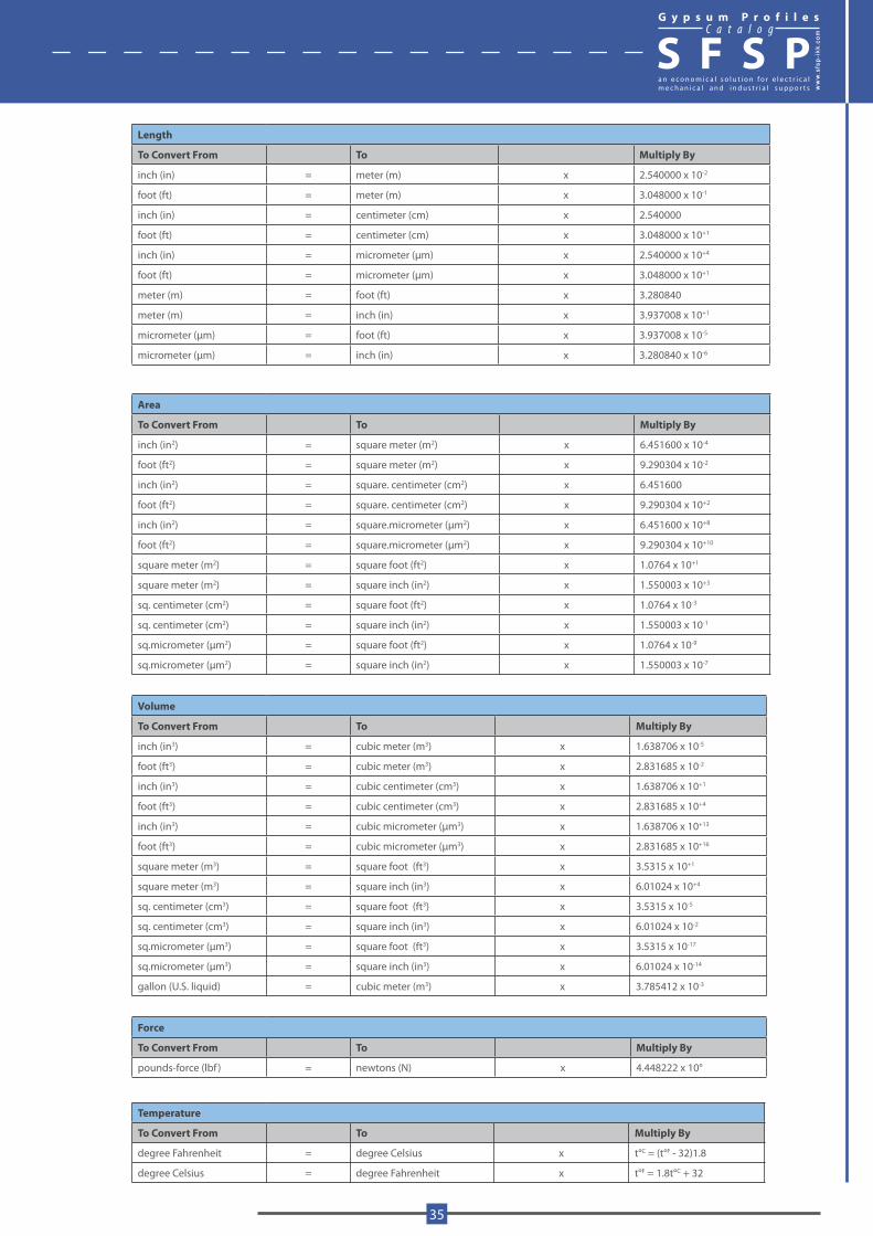
Length
To Convert From To Multiply By
inch (in) = meter (m) x 2.540000 x 10⁻²
foot (ft) = meter (m) x 3.048000 x 10⁻¹
inch (in) = centimeter (cm) x 2.540000
foot (ft) = centimeter (cm) x 3.048000 x 10+1
inch (in) = micrometer (μm) x 2.540000 x 10+4
foot (ft) = micrometer (μm) x 3.048000 x 10+1
meter (m) = foot (ft) x 3.280840
meter (m) = inch (in) x 3.937008 x 10+1
micrometer (μm) = foot (ft) x 3.937008 x 10⁻⁵
micrometer (μm) = inch (in) x 3.280840 x 10⁻⁶
Area
To Convert From To Multiply By
inch (in2) = square meter (m2) x 6.451600 x 10-4
foot (ft2) = square meter (m2) x 9.290304 x 10-2
inch (in2) = square. centimeter (cm2) x 6.451600
foot (ft2) = square. centimeter (cm2) x 9.290304 x 10+2
inch (in2) = square.micrometer (μm2) x 6.451600 x 10+8
foot (ft2) = square.micrometer (μm2) x 9.290304 x 10+10
square meter (m2) = square foot (ft2) x 1.0764 x 10+1
square meter (m2) = square inch (in2) x 1.550003 x 10+3
sq. centimeter (cm2) = square foot (ft2) x 1.0764 x 10-3
sq. centimeter (cm2) = square inch (in2) x 1.550003 x 10-1
sq.micrometer (μm2) = square foot (ft2) x 1.0764 x 10-9
sq.micrometer (μm2) = square inch (in2) x 1.550003 x 10-7
Volume
To Convert From To Multiply By
inch (in3) = cubic meter (m3) x 1.638706 x 10-5
foot (ft3) = cubic meter (m3) x 2.831685 x 10-2
inch (in3) = cubic centimeter (cm3) x 1.638706 x 10+1
foot (ft3) = cubic centimeter (cm3) x 2.831685 x 10+4
inch (in3) = cubic micrometer (μm3) x 1.638706 x 10+13
foot (ft3) = cubic micrometer (μm3) x 2.831685 x 10+16
square meter (m3) = square foot (ft3) x 3.5315 x 10+1
square meter (m3) = square inch (in3) x 6.01024 x 10+4
sq. centimeter (cm3) = square foot (ft3) x 3.5315 x 10-5
sq. centimeter (cm3) = square inch (in3) x 6.01024 x 10-2
sq.micrometer (μm3) = square foot (ft3) x 3.5315 x 10-17
sq.micrometer (μm3) = square inch (in3) x 6.01024 x 10-14
gallon (U.S. liquid) = cubic meter (m3) x 3.785412 x 10-3
Force
To Convert From To Multiply By
pounds-force (lbf ) = newtons (N) x 4.448222 x 10°
Temperature
To Convert From To Multiply By
degree Fahrenheit = degree Celsius x t°C = (t°F - 32)1.8
degree Celsius = degree Fahrenheit x t°F = 1.8t°C + 32
G y p s u m P r o f i l e sC a t a l o g
S F S P
www.sfs
p-ikk
.com
35
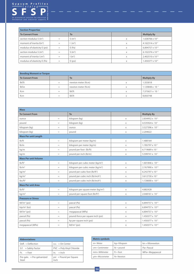
Section Properties
To Convert From To Multiply By
section modulus S (in3) = S (m3) x 1.638706 x 10-5
moment of inertia I(in4) = I (m4) x 4.162314 x 10-7
modulus of elasticity E (psi) = E (Pa) x 6.894757 x 10+3
section modulus S (m3) = S (in3) x 6.102374 x 10+4
moment of inertia I (m4) = I (in3) x 2.402510 x 10+6
modulus of elasticity E (Pa) = E (psi) x 1.450377 x 10⁻⁴
Bending Moment or Torque
To Convert From To Multiply By
lbf.ft = newton meter (N.m) x 1.355818
lbf.in = newton meter (N.m) x 1.129848 x 10 -1
N.m = lbf.ft x 7.375621 x 10 -1
N.m = lbf.ft x 8.850748
Mass
To Convert From To Multiply By
ounce = kilogram (kg) x 2.834952 x 10⁻²
pound = kilogram (kg) x 4.535924 x 10⁻¹
kilogram (kg) = ounce x 3.527396 x 10+1
kilogram (kg) = pound x 2.204622
Mass Per unit Length
lb/ft = kilogram per meter (kg/m) x 1.488164
lb/in = kilogram per meter (kg/m) x 1.785797 x 10+1
kg/m = pound per foot (lb/ft) x 6.719689 x 10⁻¹
kg/m = pound per inch (lb/in) x 5.599741 x 10⁻¹
Mass Per unit Volume
lb/ft3 = kilogram per cubic meter (kg/m3) x 1.601846 x 10+1
lb/in3 = kilogram per cubic meter (kg/m3) x 2.767990 x 10+4
kg/m3 = pound per cubic foot (lb/ft3) x 6.242797 x 10-2
kg/m3 = pound per cubic inch (lb/inch3) x 3.612730 x 10-5
lbs/ft3 = pound per cubic inch (lb/inch3) x 1.728000 x 10+3
Mass Per unit Area
lb/ft2 = kilogram per square meter (kg/m2) x 4.882428
kg/m2 = pound per square foot (lb/ft2) x 2.048161 x 10-1
Pressure or Stress
lbf/in2 (psi) = pascal (Pa) x 6.894757 x 10+3
kip/in2 (ksi) = pascal (Pa) x 6.894757 x 10+6
lbf/in2 (psi) = megapascal (MPa) x 6.894757 x 10⁻³
pascal (Pa) = pound-force per square inch (psi) x 1.450377 x 10⁻⁴
pascal (Pa) = kp per square inch (psi) x 1.450377 x 10⁻⁷
megapascal (MPa) = lbf/in2 (psi) x 1.450377 x 10+2
Abbreviations
Defl. = Deflection o.c. = On Center
S.F. = Safety Factor PVC = Poly Vinyl Chloride
Ft. = Feet In. = Inch
Pre-galv. = Pre-galvanized Steel
psi = Pound per Square Inch
Metric symbols
m= Meter kg= Kilogram kn = Kilonewton
cm= Centimeter lb = pound Pa= Pascal
mm= Millimeter ft = foot MPa= Megapascal
μm= Micrometer N= Newton
G y p s u m P r o f i l e sC a t a l o g
S F S P
36