Embed Size (px)
Citation preview

GUNDAGAI RAILWAY BRIDGE AND VIADUCTS – CONVERSION TO RAIL TRAIL
Feasibility Report
01 MAY 2018


i
CONTACT
KEN MAXWELL Technical Director, Bridges
T 02 8907 9015
Arcadis
Level 16, 580 George Street,
Sydney, NSW 2000

ii

iii
GUNDAGAI RAILWAY BRIDGE AND VIADUCTS – CONVERSION TO RAIL TRAIL
Feasibility Report
Author Ken Maxwell
Checker Syd Gamble
Approver Ken Maxwell
Report No F0001-10005572-NSR-01
Date 1st May 2018
Revision Text 01
This report has been prepared for Cootamundra-Gundagai Regional Council in
accordance with the terms and conditions of appointment dated 4th January 2018.
Arcadis Australia Pacific Pty Limited (ABN 76 104 485 289) cannot accept any
responsibility for any use of or reliance on the contents of this report by any third party.
REVISIONS
Revision Date Description Prepared by Approved by
01 01/05/2018 Draft issue to Cootamundra-Gundagai
Regional Council K Maxwell K Maxwell
V


iv
CONTENTS 1 INTRODUCTION ...................................................................................................................... 1
2 STRUCTURE CONFIGURATION ............................................................................................. 2
3 BRIDGE COMPONENTS ......................................................................................................... 3
3.1 Viaduct Trusses ................................................................................................................... 3
3.2 Viaduct Trestles ................................................................................................................... 4
3.3 Steel Truss ............................................................................................................................ 5
3.4 Steel Through Girder ........................................................................................................... 5
3.5 Bridge Piers .......................................................................................................................... 6
4 STRUCTURE CONDITION ....................................................................................................... 7
4.1 General.................................................................................................................................. 7
4.2 Northern Viaduct .................................................................................................................. 7
4.3 Main River Spans ................................................................................................................. 8
4.4 Southern Viaduct ................................................................................................................. 9
4.5 Summary............................................................................................................................. 10
5 RAIL TRAIL DECKING SYSTEM ........................................................................................... 11
5.1 Geometric Details .............................................................................................................. 11
5.2 Handrails............................................................................................................................. 11
5.3 Design Loading .................................................................................................................. 11
5.4 Slip Resistance .................................................................................................................. 11
5.5 Decking System ................................................................................................................. 11
6 REHABILITATION OF VIADUCTS ........................................................................................ 14
6.1 Timber Truss Spans .......................................................................................................... 14
6.2 Timber Pier Trestles & Abutments ................................................................................... 14
6.3 Timber Transoms ............................................................................................................... 16
6.4 Structure Rehabilitation Examples ................................................................................... 18
7 INDICATIVE COST ESTIMATES ........................................................................................... 21
7.1 Rehabilitation of Viaducts ................................................................................................. 21
7.2 Installation of Decking System ......................................................................................... 21
7.3 Summary............................................................................................................................. 21
vi
APPENDICES
Schematic Representation of Bridge and Viaducts
Inspection Photographs
Indicative Cost Estimates

1
1 INTRODUCTION
The timber viaducts and steel bridges spans at Gundagai are located on the non-operational Cootamundra
to Tumut branch line. The railway line from Cootamundra, on the Main South line, to Gundagai was opened
on 1st June 1886. The extension from Gundagai to Tumut, which includes the viaducts and bridge, was
opened on 12th October 1903, with the first train travelling across the structure on 3rd December 1903.
In March 1985, the line was officially closed, following damage to some bridges, and washaway of
embankments and cutting instability due to flooding in both August 1983 and January 1984. The last train (a
rail motor service) travelled across the Gundagai viaduct on 26th November 1983.
Cootamundra-Gundagai Regional Council engaged Arcadis to undertake the following in relation to
investigating the feasibility of incorporating Gundagai Railway Bridge and Viaducts into a possible future rail
trail:
• Undertake a site visit to inspect the structure, noting its current condition and other relevant information.
• Preparation of a Feasibility Report.
The following report provides details of the abovementioned scope of work and includes the following two
components:
Civil Engineering Component – Arcadis carried out this component of the project, being the site inspection,
listing of bridge elements that would require replacement, development of a concept design of a shared path
structure across the Murrumbidgee River steel bridge span and timber deck truss approach spans, and
preparation of the Feasibility Report.
Cost Estimating Component – MIEngineers (engaged by Arcadis) carried out this component of the
project, involving the development of a preliminary cost estimate to rehabilitate the bridge and viaducts, and
then to convert these structures for incorporation into a future rail trail.
Figure 1 – Locality Plan
Gundagai Railway
Bridge and Viaducts

2
2 STRUCTURE CONFIGURATION
The Gundagai railway bridge and viaducts comprises 3 steel spans and 77 timber spans, with an overall
length of 924.5 metres and having the following configuration:
No. Spans Span Length Span Type Structure
1 33’6” (10.2m) Timber deck Howe truss – transom top
Northern Viaduct
(72 spans)
Total length 768.5m
8 35’ (10.7m) Timber deck Howe truss – transom top
1 30’6” (9.3m) Timber deck Howe truss – transom top
62 35’ (10.7m) Timber deck Howe truss – transom top
1 68’6” (20.9m) Steel plate welded through girder – transom top Approach Span
(1 span)
1 200’ (61.0m) Steel hog-back pin-jointed through truss – transom top River Span
(1 span)
1 68’6” (20.9m) Steel plate welded through girder – transom top Approach Span
(1 span)
4 35’ (10.7m) Timber deck Howe truss – transom top Southern Viaduct
(5 spans)
Total length 53.0m 1 33’6” (10.2m) Timber deck Howe truss – transom top
The timber viaduct on the northern side of the Murrumbidgee River (Northern Viaduct) crosses two (2) public
roads, being O.I. Bell Drive and Middleton Drive, while the timber viaduct on the southern side of the
Murrumbidgee River (Southern Viaduct) crosses Tumut Street (now closed to traffic). Public access can
essentially be gained to the entire length of both the northern and southern viaducts, except for the length of
viaduct within Morleys Creek, continuing to a fence line some 70 metres north of O I Bell Drive. This length
of viaduct covers Spans 5 to 16 (inclusive).
The trestles of the viaducts (75 in total, plus 1 supplementary trestle adjacent to Abutment 1) would have
been constructed using timber piles driven into the ground. However, it is noted there are 48 trestles that are
now supported on concrete sills or walls (possibly 51, as three trestles could not be accessed).
The concrete sills (as distinct from concrete walls) would have been constructed as remediation work for
decayed timber piles at the ground line. This was a typical timber trestle repair method used on NSW
railways commencing around 1951. It was noted that some of these sills had the year ‘1963’ formed into the
concrete surface. In fact, recesses/notches in the timber piles were visible, showing the original cross
bracing configuration prior to construction of the concrete sills and reconfiguration of the timber cross
bracing.
Trestles 4, 5, 6 and 7 are all located within Morleys Creek. All of these trestles are supported on concrete
walls. It is assumed that scouring occurred sometime after the original construction, exposing the previously
buried piles. The lower sections of timber piles would likely have been removed and replaced by concrete
walls. It is also noted that the two trestles at the lagoon (Trestles 51 and 52) are similarly supported on
concrete walls.
A diagram of the configuration of the existing railway bridge and viaducts is included in Appendix A.
3
3 BRIDGE COMPONENTS
For the identification of the location of the elements in this bridge, ‘railway convention’ will be used, whereby
spans and supports (abutments and piers) are numbered from the Sydney (that is, Gundagai) end of the
viaduct. Also, the Up side represents the left-hand side of the viaduct/bridge when facing Sydney
(Gundagai), while the Down side is the opposite side of the viaduct/bridge.
The diagram provided as Appendix A shows the identification system outlined above.
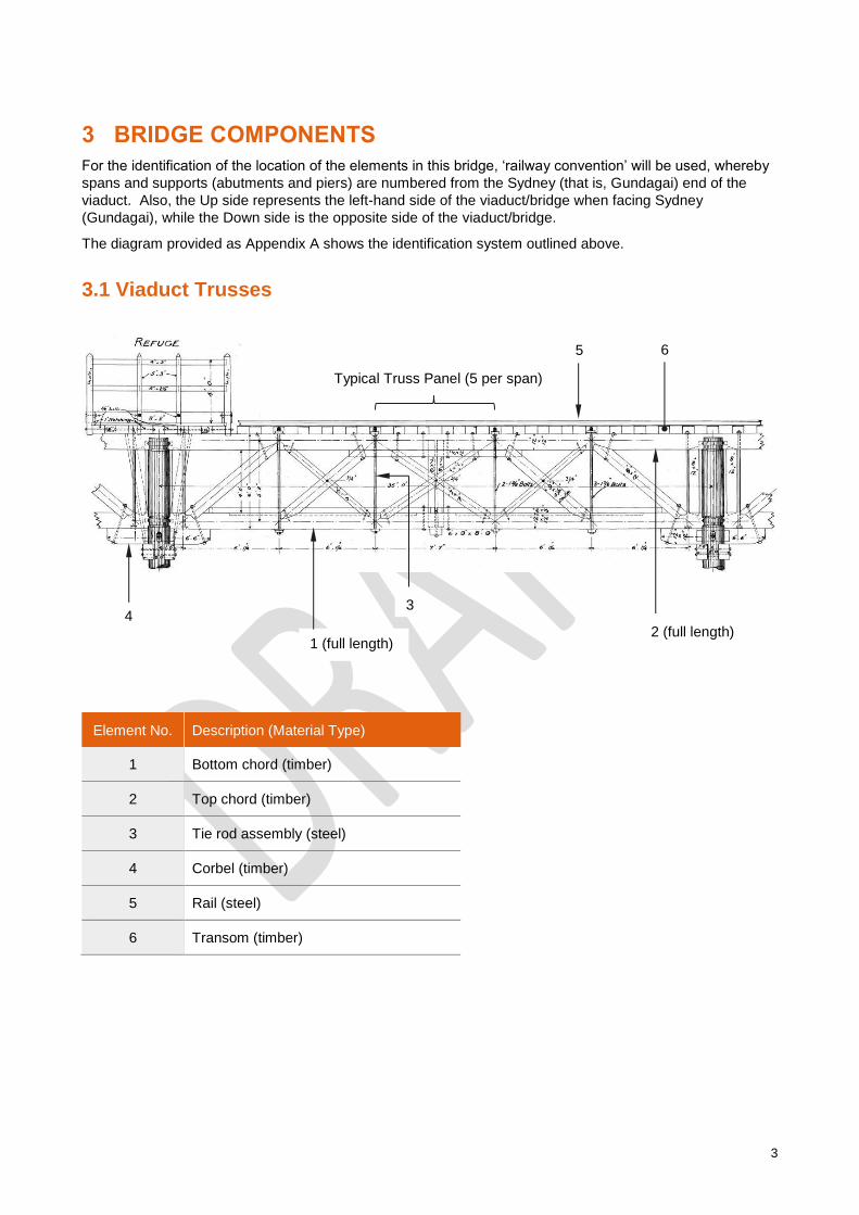
3.1 Viaduct Trusses
Element No. Description (Material Type)
1 Bottom chord (timber)
2 Top chord (timber)
3 Tie rod assembly (steel)
4 Corbel (timber)
5 Rail (steel)
6 Transom (timber)
6 5
Typical Truss Panel (5 per span)
4 2 (full length)
1 (full length)
3

4
3.2 Viaduct Trestles
Element No. Description (Material Type)
1 Cross bracing (timber)
2 Pile (timber)
3 Bottom waling (timber)
4 Upper waling (timber)
5 Capwale/headstock (timber)
A six-pile trestle is shown above, however, only Trestles 4, 5, 6, 7, 8, 51, 52, 68, 69, 70 and 71 comprise six
piles, and each of these have been modified (at an unknown date) to be supported on a concrete sill (except
trestle 8). The remaining 64 pier trestles comprise a 5-pile arrangement.
4
5
2
1
3

5
3.3 Steel Truss
Element No. Description (Material Type)
1 Bottom chord member (steel)
2 Top chord member (steel)
3 Vertical (steel)
4 End post (steel)
5 Diagonal (steel)
3.4 Steel Through Girder
Element No. Description (Material Type)
1 Main girder (steel)
2 Cross girder (steel)
3 Stringer (steel)
4 Wind bracing (steel)
3 5
4 1
2

6
3.5 Bridge Piers
The four piers that support the three steel spans are essentially mass concrete (that is, no reinforcement)
walls, with rounded ends for water flow purposes.
4
1
3 2
1
3
1
2

7
4 STRUCTURE CONDITION
4.1 General
A basic visual inspection from ground level of the timber viaducts and steel bridge spans was undertaken on
8th February 2018 by Ken Maxwell, bridge engineer and Technical Director, Bridges at the Sydney office of
Arcadis. Apart from the length of the structure (approximately 925 metres), there was no safe way to cross
the bridge at rail level due to the decayed and/or loose and unstable timber transoms and even potentially
suspect truss members. In addition, there are safety barriers erected at both ends of the viaduct to prevent
unauthorised access to the top of the viaducts.
This inspection work essentially served to update a similar inspection carried out by Ken Maxwell on 20th
November 2010 for ARTC, involving the identification of significant degradation zones in the structures.
It is noted that the extent of the condition of the timber elements is not fully known following a basic visual
inspection, as timber deterioration in the form of pipe rot (refer Figure 2) is not evident from a basic visual
inspection, as it is an internal defect. Only ground-penetrating radar techniques or timber drilling would
reveal such hidden timber deterioration.
Figure 2 – Typical Decay Mechanisms in Timber Bridge Elements: Pipe Rot (left), Trough Rot (right)
It is assumed that the entire structure would not have had any form of maintenance since 1984, following
closure of the line.
The following defects were found to be typical throughout the timber truss spans of the viaducts:
• Transoms severely weathered and split. Also, transoms are ‘bunched up’ at a number of locations.
• Vertical rods loose at some timber truss spans (evidenced by gap between plates and underside of
bottom chord).
A selection of inspection photographs is included as Appendix B.
4.2 Northern Viaduct
The ‘Northern Viaduct’ comprises the timber truss spans located on the Gundagai town side of the
Murrumbidgee River.
4.2.1 Timber Trusses
The Northern Viaduct comprises seventy-two (72) timber Howe deck truss spans that cross the
Murrumbidgee River floodplain. These trusses were found to be generally in poor to fair condition.
However, there were some bottom chord truss members that appeared weathered on their outer face.
Apart from entire loss of protective paint coating and surface corrosion, the steel or wrought iron suspension
rods appeared to be generally in fair to good condition.
Of the 72 spans, only five (5) on the southern side of Morleys Creek could not be viewed, due to restricted
access.
Details of the defects at the timber trusses of the Northern Viaduct are as follows:
• Span 4 (Down side truss) – Top and bottom chord fractured (near Trestle 4). Refer Plate 1, Appendix B.
• Span 25 (Up side truss) – Top chord of 2nd panel and top chord of 4th panel severe decay (total loss of
timber). Bottom chord weathered and split. Refer Plate 2, Appendix B.

8
• Span 30 (Up side truss) – Severe decay of top chord at 4th panel point.
• Span 49 – Detached bottom chord cross beam.
• Span 51 – Total fracture of bottom chords of each truss (at mid-span). Refer Plate 3, Appendix B.
• Span 54 – Up side bottom chord decayed at interface with missing corbel (at Trestle 53). Bottom chord
has dropped onto cap sill following loss of corbel. Refer Plate 4, Appendix B.
• Transoms severely weathered and split throughout length of viaducts and bridge spans. Also, transoms
are ‘bunched up’ at a number of locations.
4.2.2 Timber Trestles
There are seventy-one (71) timber trestles plus one (1) supplementary timber trestle. Forty-four (44) are
supported on concrete sills, which are footings typically provided as an upgrading measure when the piles
decay around ground level.
The timber trestles were generally found to be in poor to fair condition, although it was noted that the bottom
walings were typically in a deteriorated condition.
Details of the defects at the timber trestles of the Northern Viaduct are as follows:
• Trestle 16 – Decayed bottom waling and decayed upper cross-bracing. Refer Plate 5, Appendix B.
• Trestles 17 to 22 (inclusive) – Decayed bottom walings. Refer Plate 6, Appendix B.
• Trestle 23 – Broken cross-bracing. Refer Plate 7, Appendix B.
• Trestle 24 – Severely weathered bottom walings. Cross-bracing broken (on one side).
• Trestle 26 – Severely deteriorated bottom waling. Refer Plate 8, Appendix B.
• Trestle 27 – Severely deteriorated/missing timber at bottom waling.
• Trestle 29 – Severely deteriorated bottom waling.
• Trestle 39 – Down side column has vertical split. Also, severe decay at top. Refer Plate 9, Appendix B.
• Trestle 50 – Totally deteriorated bottom walings and severely deteriorated mid-height waling. Refer Plate
10, Appendix B.
• Trestle 54 – Cross-bracing cut. Mid-height waling decayed.
• Trestle 55 – Cross-bracing and bottom waling decayed.
• Trestle 56 – Cross-bracing and bottom waling decayed.
• Trestle 62 – Bottom waling decayed (at Up side end only).
• Trestle 64 – There is soil built up to the level of the bottom timber walings, potentially causing decay to
these timber elements.
4.2.3 Timber Abutment
• Sydney abutment (Abutment 1) dilapidated – In poor condition and is partially collapsed, piles broken,
timber sheeting fractured. It is noted there is a supplementary timber trestle located close to the defective
abutment, to provide additional support close to the end of the truss. Refer Plate 11, Appendix B.
4.3 Main River Spans
The main river spans comprise a single steel pin-jointed hog-back truss span across the Murrumbidgee
River, flanked by a single steel through girder approach span.

9
4.3.1 Steel Truss
• Span 74 (truss) – Apart from loss of protective paintwork on all steel elements, and subsequent surface
rust throughout, the steel truss span appeared (from a distance) to be in fair to good condition. Refer
Plate 13, Appendix B.
4.3.2 Steel Through Girder
• Span 73 (half-through girder) – Steelwork appeared (from a distance) in fair to good condition, apart from
loss of paintwork throughout and subsequent surface rust throughout. Refer Plate 12, Appendix B.
• Span 75 (half-through girder) – Steelwork appeared (from a distance) in fair to good condition, apart from
loss of paintwork throughout and subsequent surface rust throughout. Refer Plate 14, Appendix B.
4.3.3 Concrete Piers
The four (4) piers are mass concrete walls with rounded ends for water flow advantages. All appeared to be
in fair to good condition.
4.4 Southern Viaduct
The ‘Southern Viaduct’ comprises the timber truss spans located on the South Gundagai township side of
the Murrumbidgee River.
4.4.1 Timber Trusses
The Southern Viaduct comprises five (5) timber Howe deck truss spans. These trusses were found to be
generally in poor to fair condition.
There is significant sag of the Up side truss of Span 78, which is the middle span of the five spans of the
Southern Viaduct. It was noted that the Up side bottom chord truss end at Trestle 77 has decayed, resulting
in dislodgement of the end post of the truss and disconnection with the bottom chord of the adjacent truss
span, thereby causing it to sag, but still resting on the corbel. Essentially, the triangulated truss members
have lost their ‘tightness’ and the entire truss has deflected like a beam element.
Also, the span above Tumut Street (Span 80) appears distorted/twisted. The reason, however, is not
obvious, although it may have been constructed on superelevation, as the viaduct is on a horizontal curve at
the Tumut end.
Apart from entire loss of protective paint coating and surface corrosion, the steel or wrought iron suspension
rods appeared to be generally in fair to good condition.
Details of the defects at the timber trusses of the Southern Viaduct are as follows:
• Span 78 – Up side truss sagging.
• Span 78 – Up side bottom chord crushed (near Trestle 78).
• Span 78 – Up side bottom chord entirely decayed locally (near Trestle 77).
4.4.2 Timber Trestles
There are four (4) timber trestles and all are supported on concrete sills that project above ground level.
The timber trestles were generally found to be in poor to fair condition, although it was noted that the bottom
walings were typically in a deteriorated condition.
Details of the defects at the timber trestles of the Southern Viaduct are as follows:
• Trestles 76, 78 and 79 – Headstock deteriorated at ends.

10
4.4.3 Timber Abutment
• Country abutment (Abutment 2) dilapidated – In poor condition with dislodged and broken timber
sheeting, embankment scoured out during 2012 flood.
• Abutment 2 – Headstock deteriorated at ends.
4.5 Summary
Overall, the timber viaducts vary from poor to fair in condition, and the steel spans are in fair to good
condition.

11
5 RAIL TRAIL DECKING SYSTEM
5.1 Geometric Details
The ‘desirable minimum width’ is 2500 mm for shared paths under the category of ‘local access path’ in
Table 7.4 of the Austroads document entitled Guide to Road Design Part 6A: Pedestrian and Cyclist Paths.
For the proposed rail trail decking across Gundagai viaducts and bridge, a horizontal distance between
handrails of 2500 mm is proposed.
5.2 Handrails
For the required configuration of the handrailing system, clause 16.2.2 of AS 5100.1:2017 Bridge design Part
1: Scope and general principles is the recommended guiding document.
For bridges where cyclists will be present, the minimum barrier height shall be 1.4 m from the walkway
surface.
5.3 Design Loading
For pedestrian bridges, the live load is determined in accordance with Figure 8.1, AS 5100.2:2017 Bridge
design Part 2: Design loads, whereby the load intensity is based on the loaded area. Depending on the
loaded area considered, the maximum design live load intensity is 5kPa (unfactored).
5.4 Slip Resistance
For slip resistance of the pedestrian surface, materials used shall conform to AS/NZS 3661.2:1994 Slip
resistance of pedestrian surfaces Part 2: Guide to the reduction of slip hazards, taking into consideration the
slope of the surface.
5.5 Decking System
The concept decking systems assume the retention of the existing rails, inner guardrails and timber transoms
and comprise one of the following materials:
• Timber decking planks; or
• Fibre reinforced polymer decking planks; or
• Recycled plastic decking such as Enduroplank™.
In order to use transverse decking planks (whether timber or composite fibre), joists will be required to be
installed on top of the existing timber transoms, running parallel to the rails, in three lines. These joists may
either comprise timber (200 mm x 75 mm) or fibre reinforced polymer rectangular hollow sections (200 mm x
100 mm bonded rectangular beams).
Kerbs are proposed along both edges of the deck (minimum height 100 mm), to provide a stable attachment
for the handrailing.
Timber transoms are typically 2850 mm in length. The rail size likely across Gundagai viaducts and bridge is
53 kg/m (107 lb/yard), whereby the height from top of rail to top of transom is 170 mm. Hence, joists 200
mm in height would provide sufficient clearance for the propose transverse decking to clear the existing rails.
It is envisaged that the decking system and handrailing will be similar to that installed across Waterford Black
Bridge in Ontario Canada (refer Figure 3).
The proposed decking system is shown in Figure 4. Although this shows the decking installed on the timber
truss spans, the same principle applies to the steel main spans over Murrumbidgee River.

12
Figure 3 – Waterford Black Bridge, Ontario Canada
Figure 4 – Proposed Decking System for Gundagai Viaducts (Timber Truss Span Shown)

13
The concept decking system shown in Figure 4 would be superimposed onto the existing timber transoms
across the timber truss spans (refer Figure 5) and across the steel through girder and steel truss spans (refer
Figure 6).
Figure 5 – Top of Typical Timber Viaduct Spans
Figure 6 – Top of Steel Bridge Spans

14
6 REHABILITATION OF VIADUCTS
Prior to the installation of a shared path decking system on the viaducts and bridge, the rehabilitation of the
timber truss viaduct spans (including timber pier trestles and timber abutments) are required to be
undertaken.
From ground level, Arcadis undertook a basic visual inspection only of the viaducts and bridge, which was all
that was required in the scope of work. This type of inspection only provided a general appreciation of the
condition of the viaducts, as timber deterioration is often hidden within the timber element itself.
Notwithstanding, it was evident that many timber elements were in an advanced state of deterioration, and
that replacement of those elements on a like-for-like basis would be recommended.
Essentially, the only way of quantifying the amount of deteriorated timber to be replaced is to estimate this in
terms of a percentage.
Section 3 of this document contains descriptions of the bridge components.
6.1 Timber Truss Spans
There are 78 timber truss spans in total, each comprising 2 timber top chords (full length elements), 2 timber
bottom chords (full length elements), 16 timber diagonals (4 are double members), 12 steel tie rod
assemblies (comprising 1, 2 and 3 bolts), 2 timber wind braces, 4 timber end posts, 2 timber cross-bracing
elements (at mid-span), 1 timber bottom chord connection element (at mid-span).
The indicative cost estimate is based on replacing 30% of all timber truss elements that make up the truss
spans, including corbels.
Typical Timber Truss Span (February 2018):
6.2 Timber Pier Trestles & Abutments
There are 2 abutments and 75 timber trestle piers. The timber pier trestles typically comprise 5 timber piles,
except for 11 of the taller trestles, which comprise 6 timber piles (refer section 4 of this document). The
length of the pile above ground level (and to about 1 metre below ground level) usually deteriorates.
Typically, the deteriorated length of pile is removed and a new length of timber is spliced in position with a
timber column of the same/similar diameter (refer section 5 of this document for an illustrated example).
15
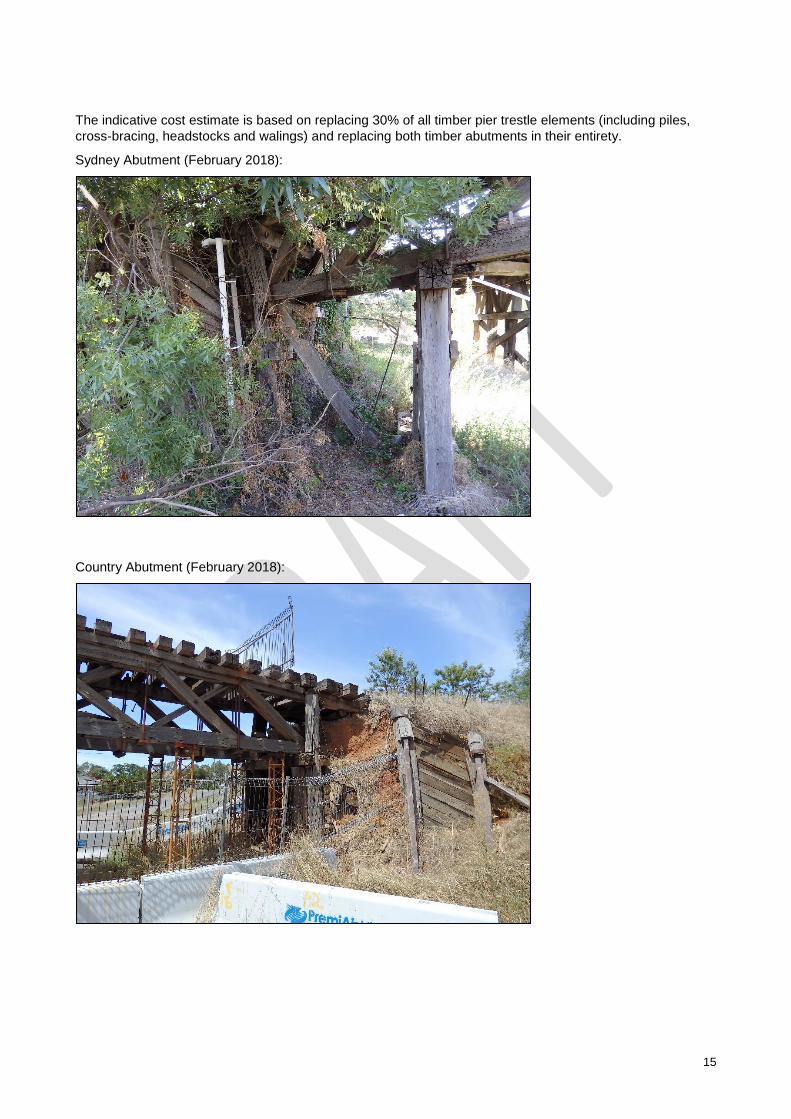
The indicative cost estimate is based on replacing 30% of all timber pier trestle elements (including piles,
cross-bracing, headstocks and walings) and replacing both timber abutments in their entirety.
Sydney Abutment (February 2018):
Country Abutment (February 2018):

16
As a comparison, the following photo is of the Country abutment at Gundagai in November 2010.
Country Abutment (November 2010):
Typical Timber Trestle (February 2018):
6.3 Timber Transoms
As the proposed shared path decking system will be supported by the timber transoms (larger version of
sleepers), it is recommended that many of these be replaced, as they are very likely in deteriorated
condition. As the overall length of the bridge and viaducts is approximately 925 metres, it is estimated that

17
there are around 1,850 timber transoms that the existing rails are attached to (assuming transoms are
spaced at 500 mm).
The indicative cost estimate is based on replacing 50% of all timber transoms. Transoms are typically 250
mm W x 165 mm D x 2850 mm long.
Timber Transom Typ.

18
6.4 Structure Rehabilitation Examples
Replacement of timber piles:
Replacement pile
Spliced to existing
cut-down pile by
steel angles

19
Abutment rehabilitation would be essentially based on the following drawing extracts:
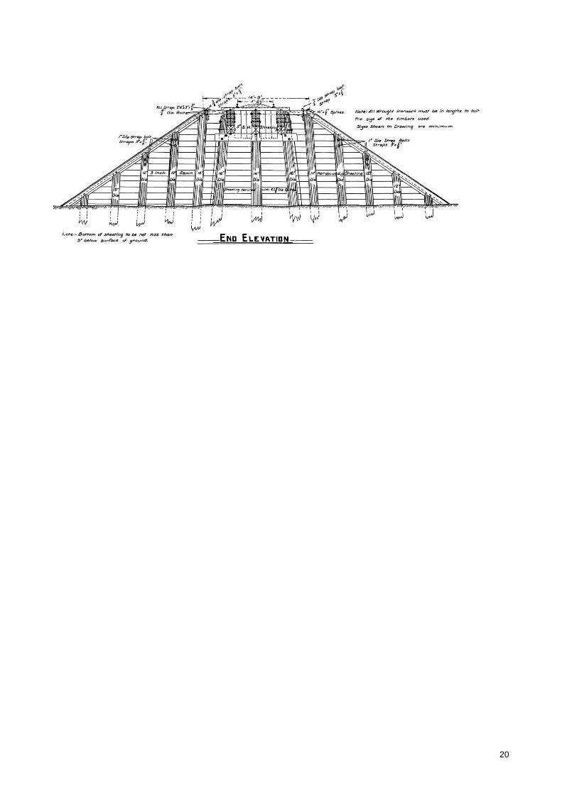
20

21
7 INDICATIVE COST ESTIMATES
For the indicative cost estimates, two components of costings were determined, as follows:
• Rehabilitation of the existing timber viaducts.
• Installation of decking and handrailing for a shared path rail trail along the entire viaducts and bridge
spans.
The indicative cost estimates were prepared by MIEngineers. Cost estimate details are included as
Appendix C. The proposed methodologies for the rehabilitation of the timber viaducts and the subsequent
installation of the timber decking for shared path conversion were developed by MIEngineers.
The rehabilitation works and the timber decking installation were based on the first principle approach of cost
estimating. This includes the supply and delivery of timber decking materials and proprietary Moddex
Bikesafe Bikeway barriers, which were supported with quotations from suppliers. However, the supply costs
of timber elements for the rehabilitation works were based on the rate derived from the supply of timber for
the bridge decking works.
7.1 Rehabilitation of Viaducts
Estimating the extent of rehabilitation required is somewhat challenging when based on a ground-level visual
inspection only. For rehabilitation of the timber viaducts, it was assumed that a percentage of the total
amount of timber would require replacement. As for the steel spans, they generally appeared in fair to good
condition, apart from paint loss throughout and consequent surface rust.
To develop an indicative cost estimate, the following rehabilitation assumptions were applied:
• Replacement of 30% of all timber truss elements that make up the truss spans, including corbels.
• Replacement of 30% of all timber pier trestle elements (including piles, cross-bracing, headstocks and
walings) and replacing both timber abutments in their entirety.
• Replacement of 50% of all timber transoms.
The indicative cost estimate for the rehabilitation of the timber viaducts is $13,660,000, which includes a
contingency of 40%.
7.2 Installation of Decking System
The indicative cost estimate includes the installation of decking and handrailing for a shared path rail trail
along the entire viaducts and bridge spans, totalling approximately 925 metres, based on the arrangement
shown in Figure 4 of this document.
The indicative cost estimate for the supply and installation of a shared path decking system is $5,955,000,
which includes a contingency of 40%.
7.3 Summary
The overall indicative cost estimate to rehabilitate the timber viaducts and install a shared path decking
system across the entire Gundagai viaducts and bridge spans is $19,615,000, which includes a contingency
of 40%.


Schematic Representation of Bridge and Viaducts

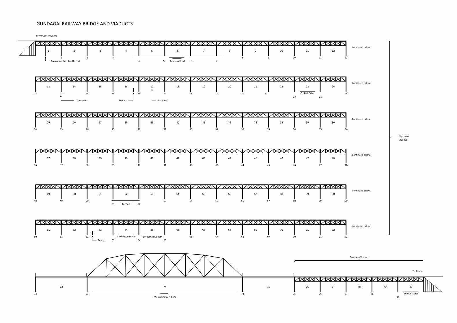
GUNDAGAI RAILWAY BRIDGE AND VIADUCTS
From Cootamundra
Continued below
1 2 3 4 5 6 7 8 9 10 11 12
Supplementary trestle (1a)
Continued below
13 14 15 16 17 18 19 20 21 22 23 24
21
Fence
Continued below
25 26 27 28 29 30 31 32 33 34 35 36
Northern
Viaduct
Continued below
37 38 39 40 41 42 43 44 45 46 47 48
Continued below
49 50 51 52 53 54 55 56 57 58 59 60
Continued below
61 62 63 64 65 66 67 68 69 70 71 72
Fence
76 77 78 79 80
78
79
Span No.Trestle No.
69 70 71 72
77
46 47 48
53 54 55 56
72 73 74 75 76
60 61 62
63 64
57 58 59 60
36 37 38 39 40
24 25 26 27 28
12
51
504948
52
14 15 16 17 18 19 20
22 23
2412
8 9 10 111 2 3
4 5
Murrumbidgee River
Tumut Street
Middleton Drive Footpath/bike path
O I Bell Drive
Southern Viaduct
To Tumut
29 30 31 32 33 34 35 36
41
73 74 75
Morleys Creek
Lagoon
6 7
13
42 43 44 45
65
66 67 68


Inspection Photographs


Plate 1 – Fractured Top & Bottom Chords, Span 4, Down Side Truss (near Trestle 4)
Plate 2 – Severe Decay at Top Chord, Span 25, Up Side Truss

Plate 3 – Fractured Bottom Chord, Span 51, Up Side & Down Side Trusses
Plate 4 – Missing Corbel & Bottom Chord Decayed, Span 54 (at Trestle 53), Up Side Truss

Plate 5 – Decayed Upper Cross-Bracing, Trestle 16
Plate 7 – Decayed Bottom Walings (Typical for Trestles 17 to 22 (inclusive))

Plate 8 – Broken Lower Cross-Bracing, Trestle 23
Plate 9 – Severely Deteriorated Bottom Waling, Trestle 26

Plate 10 – Split & Decay, Down Side Pile, Trestle 39
Plate 11 – Deteriorated Mid-Height Walings, Trestle 50

Plate 12 – Dilapidated Abutment 1
Plate 13 – Span 73

Plate 14 – Span 74
Plate 15 – Span 75

Plate 16 – Sagging Up Side Truss, Span 78
Plate 17 – Bottom Chord Crushed, Up Side Truss (near Trestle 78), Span 78
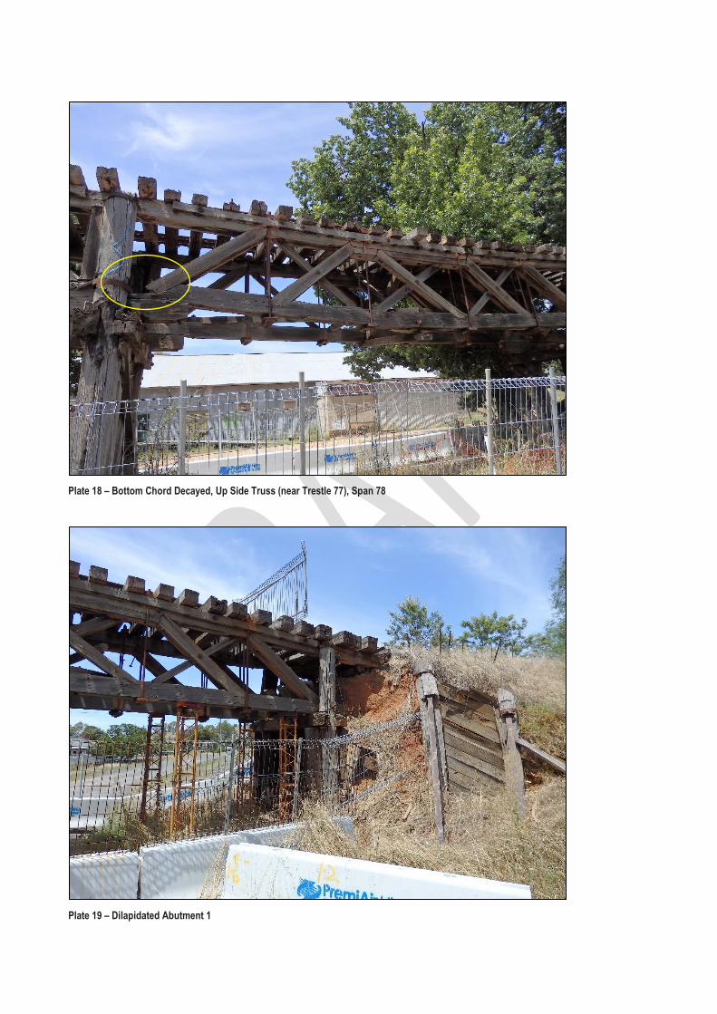
Plate 18 – Bottom Chord Decayed, Up Side Truss (near Trestle 77), Span 78
Plate 19 – Dilapidated Abutment 1


Indicative Cost Estimates


Gundagai Railway Bridge - Rehabilitation Works
Indicative Cost Estimate of Rehabilitation Works of Timber Elements
Item Description Quantity Unit Rate Amount
1 Timber Truss Spans
a) Supply and delivery of top and bottom chord -12"x12"x35' 94 no. $5,670 $532,980
b) Supply and delivery of diagonal vertical cross bracing (various
sizes)
i) 9" x 12" x 9' 94 no. $1,094 $102,836
ii) 4 1/2" x 9" x 9' 187 no. $410 $76,670
iii) 3" x 5" x 9' 94 no. $152 $14,288
iv) 7" x 7" x 9' 94 no. $496 $46,624
c) Supply and delivery of tie rods 468 no. $544 $254,592
d) Supply and delivery of end posts 8" x 12" x 6' 94 no. $648 $60,912
e) Supply and delivery of horizontal wind braces 5" x 6" x 12' 47 no. $405 $19,035
f) Supply and delivery of cross bracing at midspan 7" x 6" x 6' 47 no. $284 $13,348
g) Supply and delivery of bottom chord connection element at
midspan 7" x 6" x 6'
23 no. $284 $6,532
h) Supply and delivery of top stiffeners 5" x 12" x 12' 48 no. $810 $38,880
i) Supply and delivery of bottom stiffeners 5" x 6" x 32' 48 no. $1,080 $51,840
j) Supply and delivery of corbel 12" x 12" x 6.5' 45 no. $1,053 $47,385
2 Timber Pier and Abutment Trestles
a) Supply and delivery of timber piles 124 no. $2,025 $251,100
b) Supply and delivery of cross bracings, upper and bottom walings
9" x 4 1/2" x 10'
360 no. $456 $164,160
c) Supply and delivery of capwale/headstock 12" x 8 " x 12' 45 no. $1,296 $58,320
3 Timber Transoms
a) Supply and delivery of timber transoms 9' 6" x 6" x 10' 925 no. $641 $592,925
4 Supply of Miscellaneous Materials for Timber Replacement
a) Supply of miscellaneous materials 24 no. $2,700 $64,800
5 Design and Documentation of Methodology of Timber
Rehabilitation Works
a) Design and engineering works 1 item $39,150 $39,150
6 Procurement, Fabrication and Delivery of Structural Steel
Portal Frames for the Rehabilitation Works, including Ancillary
Items
a) Structural steel column support for top and bottom chords 10 t $10,125 $101,250
b) Structural steel beam support for top and bottom chords 5 t $10,125 $50,625
c) Structural steel column support for bearers supporting the
timber transoms
4 t $10,125 $40,500
d) Structural steel bearer supporting timber transoms 5 t $10,125 $50,625
e) Diagonal bracings for structural steel column support 8 each $1,620 $12,960
f) Flat jacks, copper tubing, valves and hydraulic oil 64 no. $540 $34,560
g) Bolts, nuts and washers 1,000 units $14 $13,500
h) Precast concrete blocks for structural steel column footings 8 no. $675 $5,400

7 Equipment and Minor Tools
a) Elevated working platform 24 months $44,550 $1,069,200
b) Franna Cranes 24 months $45,857 $1,100,568
c) Tray truck with hiab 24 months $25,769 $618,456
d) Mobile scaffolding access 24 months $3,037 $72,888
e) Minor tools and hire equipment 1 item $81,000 $81,000
8 Rehabilitation of Trusses, Transoms and Pier Trestles
a) Replacement of timber elements for timber truss spans and
timber transoms - 30% only
24 no. $97,118 $2,330,832
b) Replacement of timber pile columns and bracings - 30% only 25 no. $66,218 $1,655,450
9 Disposal of Timber Elements
a) Transport and disposal of timber trestles 124 no. $286 $35,464
b) Transport and disposal of timber elements 2,714 no. $17 $46,138
Total $9,755,793
Contingency 40 % $3,902,317
Total Indicative Price including Contingency $13,658,110
Assumptions:
Based on a single construct only contract
Unit rate per board feet of timber is based on actual supply costs of timber decking for pedestrian and cyclist bridge
Estimate excludes EPA waste levy for disposal of material off site
Estimate based on a contract duration of 24 months
Base date is Q2/2018
Excludes GST and inflation
Excludes non construction costs for concept design, detailed design and superintendence

Gundagai Railway Bridge - Cyclist and Pedestrian Bridge Decking
Indicative Cost Estimate of Timber Decking System for Pedestrian and Cyclist Shared Path
Item Description Quantity Unit Rate Amount
Area of the bridge 2,313.00 m2 $1,839.09 $4,253,808
1 Supply and Delivery of Timber Decking Elements
a) Supply and delivery of timber decking elements 925 m $1,400 $1,295,000
2
Supply and Delivery of Moddex Bikesafe Bikeway Balustrade
a) Supply and Delivery of Moddex Bikesafe Bikeway Standard
Balustrade Top Mount
1,850 m $428 $791,800
3 Design and Documentation of Methodology of Installation of
Timber Decking and Moddex Bikesafe Balustrade
a) Design and engineering works 1 item $39,150 $39,150
4 Equipment and Minor Tools
a) Elevated working platform 47 week $10,125 $475,875
b) Franna Cranes 47 week $10,424 $489,928
c) Tray truck with hiab 47 week $5,857 $275,279
d) Mobile scaffolding access 47 week $277 $13,019
e) Minor tools and hire equipment 1 item $157,950 $157,950
5 Installation of Timber Decking and Moddex Bikesafe Bikeway
Barriers
a) Supply, fabrication, installation, removal and re-installation of
safety screens on timber viaduct
1,647 m $95 $156,503
b) Supply, fabrication, installation, removal and re-installation of
safety screens on the steel structure bridge
203 m $213 $43,154
c) Supply, installation and removal of temporary sheet covering on
timber transoms
925 m2 $47 $43,475
d) Trim top of timber transoms and level ready to receive timber
joist
2,775 m $53 $147,075
e) Install timber joists 2,775 m $40 $111,000
f) Install timber decking and kerbs 925 m $108 $99,900
g) Install Moddex Bikesafe Bikeway Barriers 1,850 m $62 $114,700
Total $4,253,808
Contingency 40 % $1,701,523
Total Indicative Price including Contingency $5,955,331
Assumptions:
Based on a single construct only contract
Estimate excludes EPA waste levy for disposal of material off site
Estimate based on a contract duration of 47 weeks
Base date is Q2/2018
Excludes GST and inflation
Excludes non construction costs for concept design, detailed design and superintendence