Embed Size (px)
Citation preview

10/13/2015
1
The non‐linear behaviour of inflatable structures, collapse load and windtunnel analysis
Alexis Bloch (PhD)
Thesis Supervisor: Marc FRANCOISCo‐supervisor : Jean‐Christophe THOMASCo‐supervisor: Olivier FLAMAND (CSTB)
GUIMARÃESSeptember 9th, 2015
1
• Context
• Models development and improvement
• New measurement methods
• Experimental works
• Conclusions
Outlines
2
10/13/2015
2
• Membrane structures are increasly used in C.Eng :
Campus Luigi Einaudi, Turin.
© Michele D'Ottavio
© AIA Lyon
Great Mosquee of Paris.
© Abaca ‐ N. Pauli
Wealthness center, Montpellier. Solar Impulse Sheltering building.
Inflatable dome for football ground.
Pressurized MembranesMechanicallytensioned membranes
3
Context
• How to define limit‐states for inflable beams ?
Serviceability Limit State (SLS) Ultimate Limit State (ULS)Associated to the structural state, or some parts ofthe structure, creating limited damage or makingthe structure unuseable in respect with designrecommendations defined at the begining of theproject. (functionability, aspect,…).
Related to a partial or total collapse of the structureand call into questions the safety of shelteredpeople or equipment.
©J. Llorens
SLS Examples. ULS Examples.
©AP
Thesis context :• SLS : Wrinkle and displacement• ULS : Collapse
Context
4
10/13/2015
3
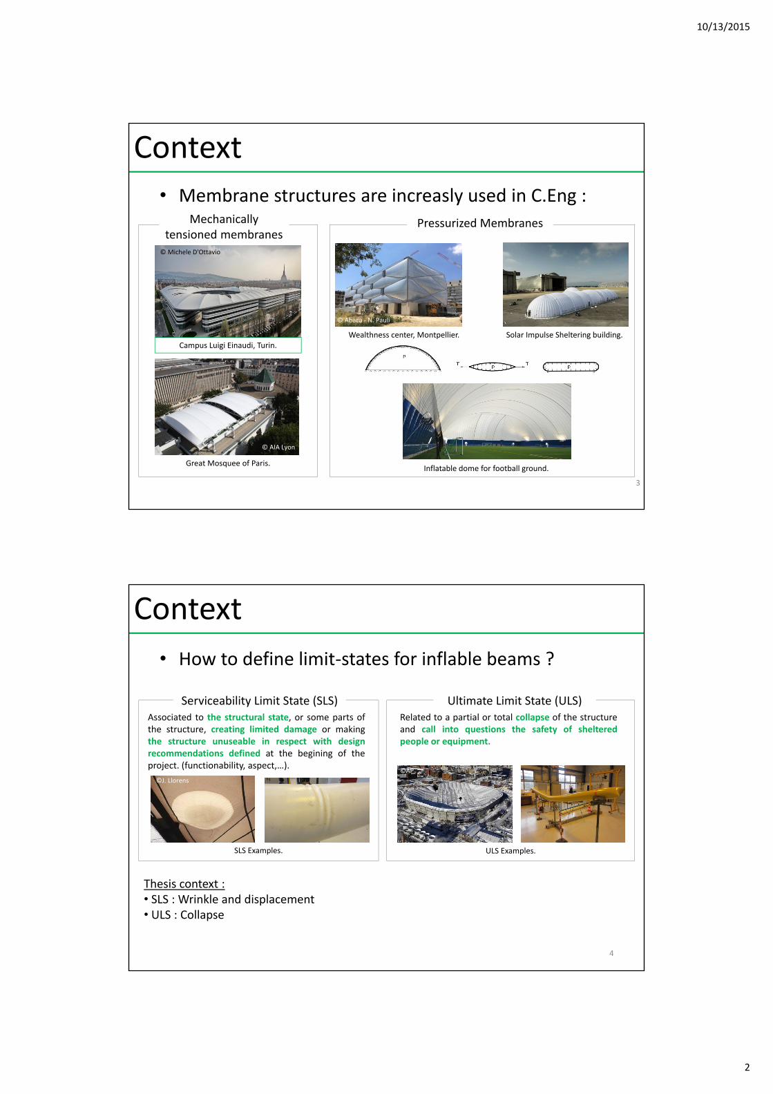
• Theoretical developments :
0 5 10 15 20 25 30 350
10
20
30
40
50
60
70
Wrinkle apparition :Loss of linear behaviour
Collapse
v(m)
F(N)
Load‐displacement curve for an inflatable beam under 3 points bending.
Aims :1. Identify the collapse load for an inflatable beam.2. Describe the post‐wrinkling behaviour.
Wrinkle propagates CollapseLinearpart
Comer et Levy (1963)Fichter (1966)
Main et al. (1995)Le Van et al. (2005)Apedo et al. (2009)Nguyen et al. (2015)
Stein et al. (1964)Ligaro et Barsotti (2012)
Comer et Levy (1963)Stein et al. (1964))
Wielgosz et al. (2002)Thomas (2002)
Ligaro et Barsotti (2012)
Models
5
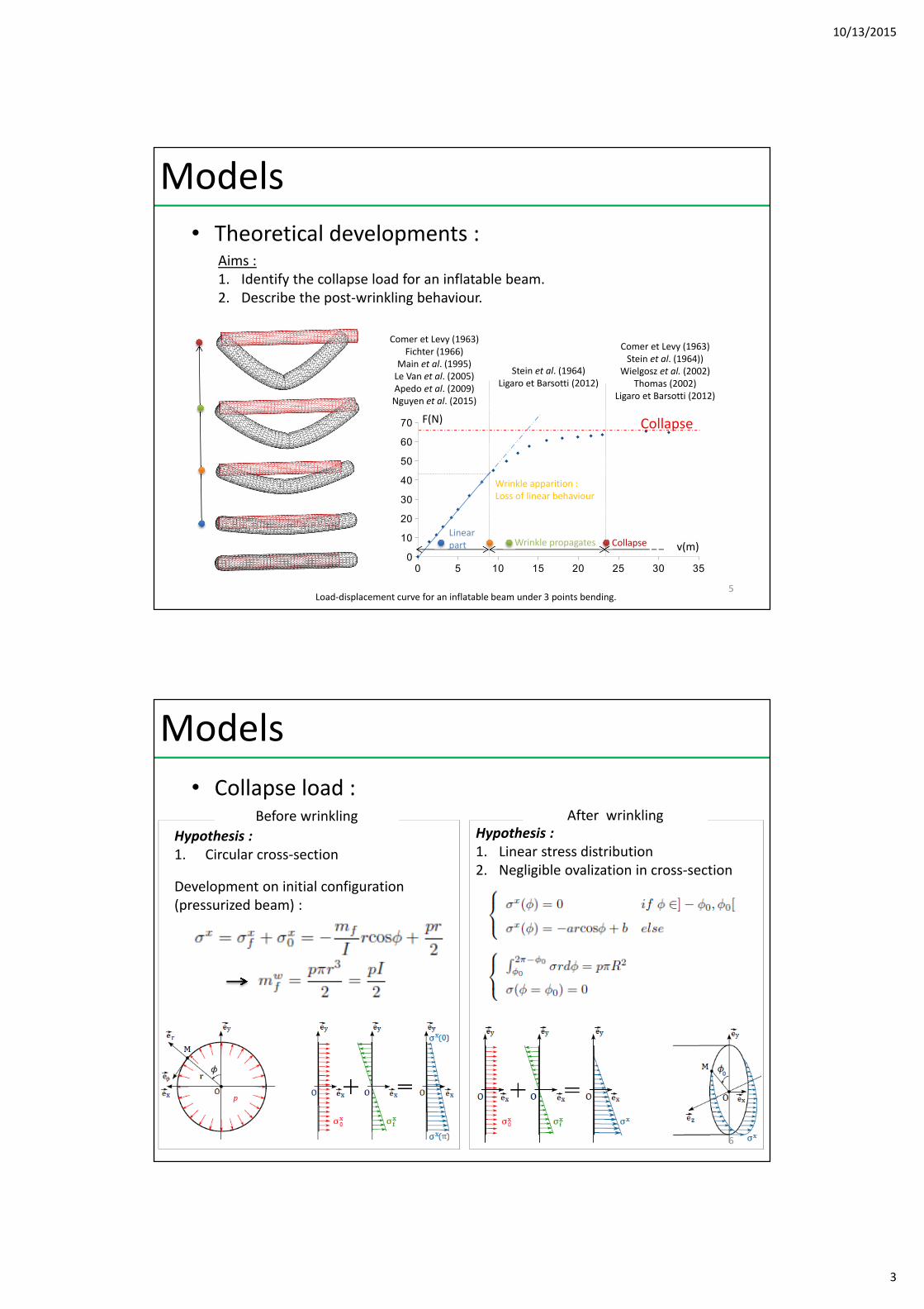
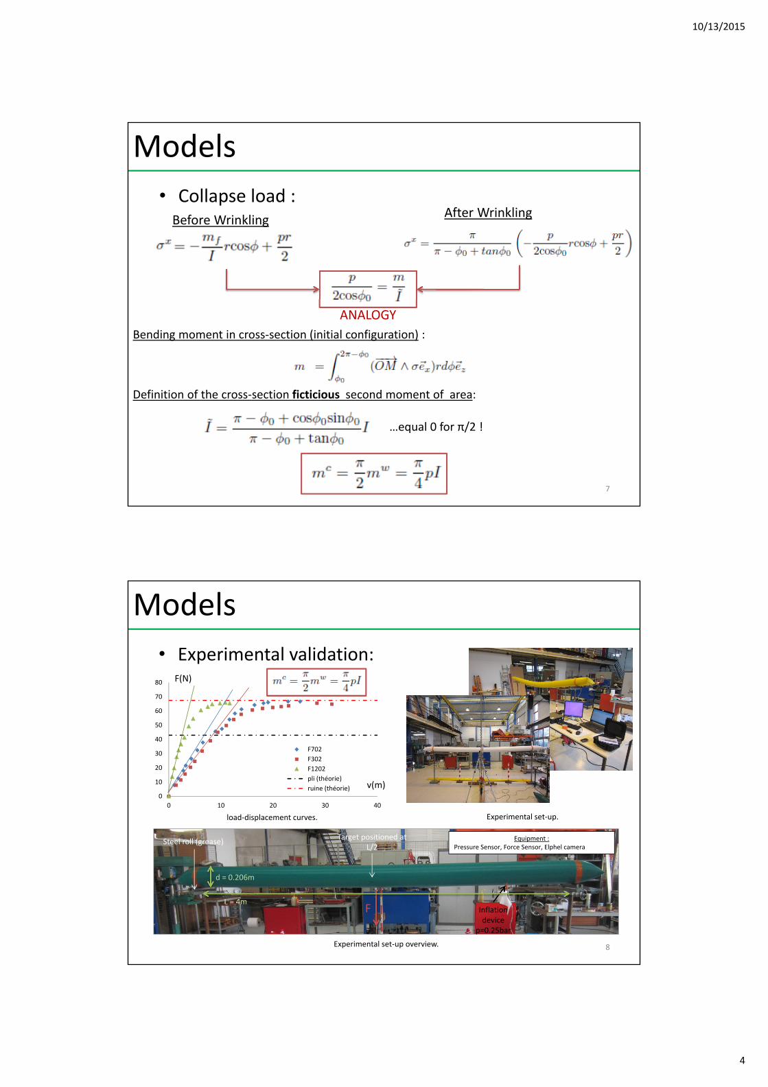
• Collapse load :
Hypothesis : 1. Circular cross‐section
Hypothesis :1. Linear stress distribution2. Negligible ovalization in cross‐section
Before wrinkling After wrinkling
Development on initial configuration (pressurized beam) :
Models
6
10/13/2015
4
• Collapse load :Before Wrinkling
After Wrinkling
ANALOGY
…equal 0 for π/2 !
Bending moment in cross‐section (initial configuration) :
Definition of the cross‐section ficticious second moment of area:
Models
7
• Experimental validation:
d = 0.206m
L = 4mF
Steel roll (grease)Target positioned at
L/2
Inflationdevice
p=0.25bar
Equipment : Pressure Sensor, Force Sensor, Elphel camera
Experimental set‐up overview.
0 10 20 30 40
0
10
20
30
40
50
60
70
80
F702
F302
F1202
pli (théorie)
ruine (théorie) v(m)
F(N)
load‐displacement curves. Experimental set‐up.
Models
8
10/13/2015
5
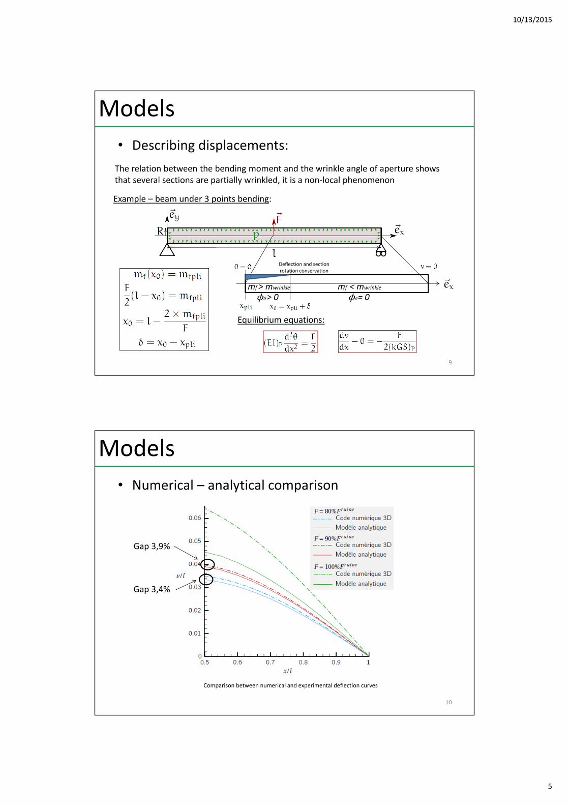
• Describing displacements:
The relation between the bending moment and the wrinkle angle of aperture shows that several sections are partially wrinkled, it is a non‐local phenomenon
Example – beam under 3 points bending:
Deflection and section rotation conservation
Equilibrium equations:
mf> mwrinkle mf < mwrinkle
ϕ0> 0 ϕ0= 0
Models
9
• Numerical – analytical comparison
Comparison between numerical and experimental deflection curves
Models
10
Gap 3,4%
Gap 3,9%
10/13/2015
6
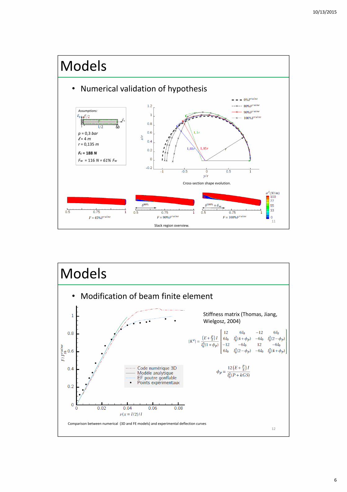
• Numerical validation of hypothesis
Cross‐section shape evolution.
Slack region overview.
Assumptions:
p = 0,3 barl = 4mr = 0,135 m
Fc = 188 N
Fw = 116 N = 61% Fw
Models
11
• Modification of beam finite element
Models
Comparison between numerical (3D and FE models) and experimental deflection curves
12
Stiffness matrix (Thomas, Jiang, Wielgosz, 2004)

10/13/2015
7
• Adressed issue :Large displacements : need for specific toolsFull‐field measurement, contactless method.
• Virtual Image Correlation (VIC) :From DIC [Semin, François]: Initial state is a virtual image.The virtual image is created from a reference solution (theoretical or numerical).The virtual image ranges from black (0) to white (1) to ensure the contour detection.
Virtual Image Construction.
Before VIC After VIC
VIC Principle.
Measurement
13
• Virtual Image Correlation (VIC) :Inflatable beam under 3 points flexure (test) :
Kf 3xKfKc
Identification (VIC) : Kf = 0,0247 (0,0250 applied); Kc = 0,0127 (0,0125 applied);
VIC Principle.
Measurement
14
10/13/2015
8
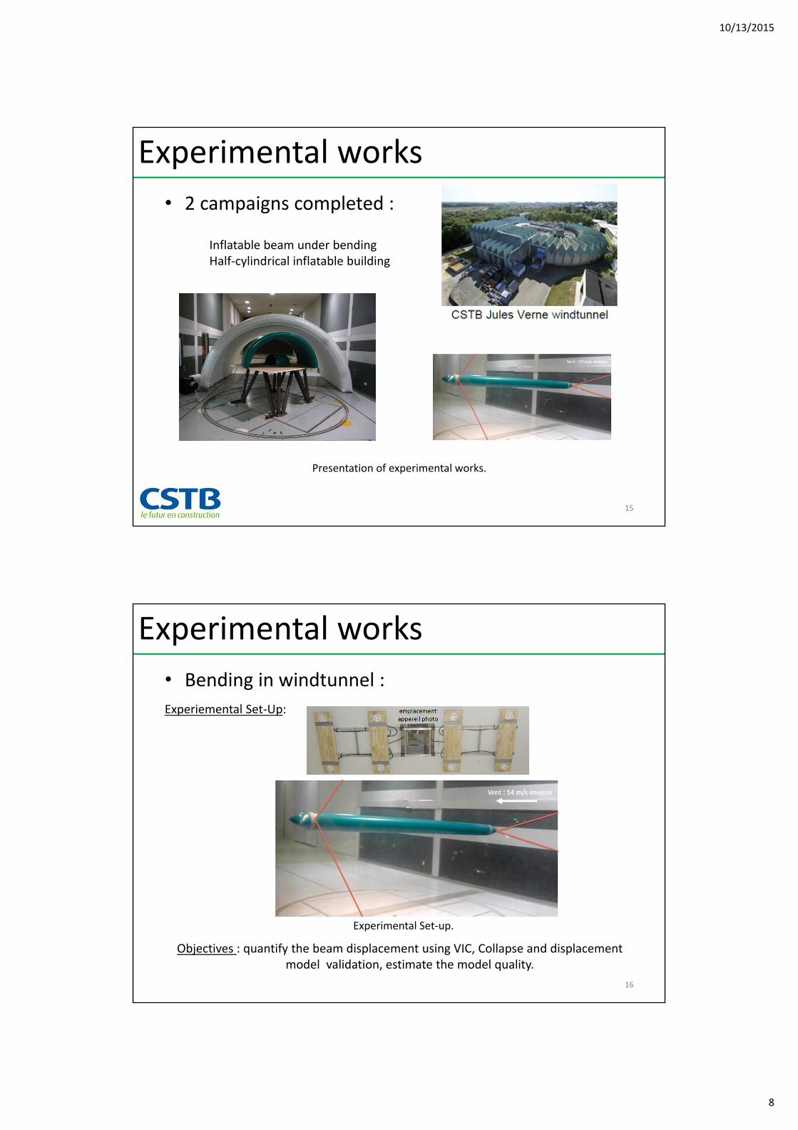
• 2 campaigns completed :
Inflatable beam under bendingHalf‐cylindrical inflatable building
Presentation of experimental works.
Experimental works
15
• Bending in windtunnel :
Experiemental Set‐Up:
Objectives : quantify the beam displacement using VIC, Collapse and displacementmodel validation, estimate the model quality.
Experimental Set‐up.
Experimental works
16
10/13/2015
9
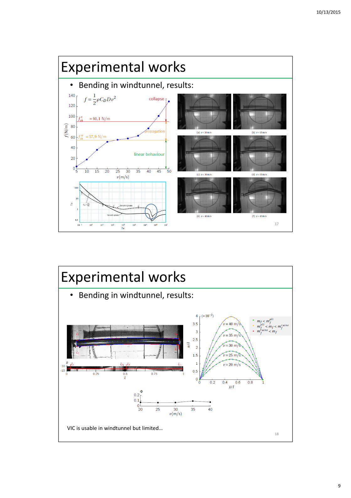
• Bending in windtunnel, results:
20 m/s0.3 bar
Experimental works
17
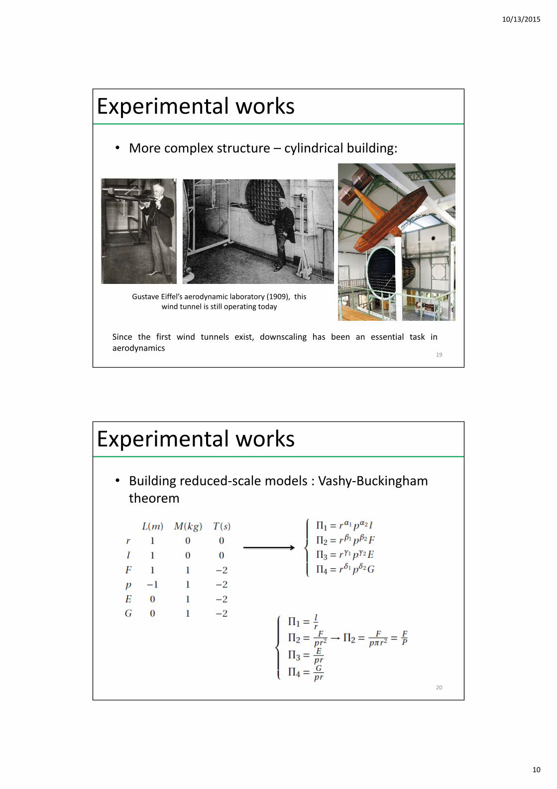
• Bending in windtunnel, results:
20 m/s0.3 bar
Experimental works
VIC is usable in windtunnel but limited…18
10/13/2015
10
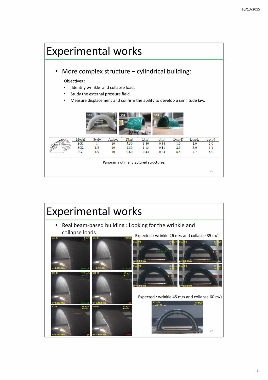
• More complex structure – cylindrical building:
Experimental works
Gustave Eiffel’s aerodynamic laboratory (1909), this wind tunnel is still operating today
Since the first wind tunnels exist, downscaling has been an essential task inaerodynamics
19
• Building reduced‐scale models : Vashy‐Buckingham theorem
Experimental works
20
10/13/2015
11
• More complex structure – cylindrical building:
SG1 SG2 SG3
Panorama of manufactured structures.
Experimental works
Objectives :
• Identify wrinkle and collapse load.
• Study the external pressure field.
• Measure displacement and confirm the ability to develop a similitude law.
21
• Real beam‐based building : Looking for the wrinkle and collapse loads.
p = 0,03 bar
Experimental works
22
Expected : wrinkle 26 m/s and collapse 35 m/s
Expected : wrinkle 45 m/s and collapse 60 m/s
10/13/2015
12
• Real beam‐based building : external pressure‐field
p = 0,03 bar
Experimental works
23
Sensors geometry
Sensors quality test
wind
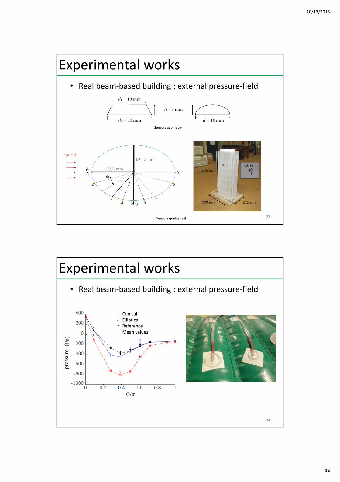
• Real beam‐based building : external pressure‐field
p = 0,03 bar
Experimental works
24
ConicalEllipticalReferenceMean values
pressure
10/13/2015
13
• Real beam‐based building : external pressure‐field
p = 0,03 bar
Experimental works
25
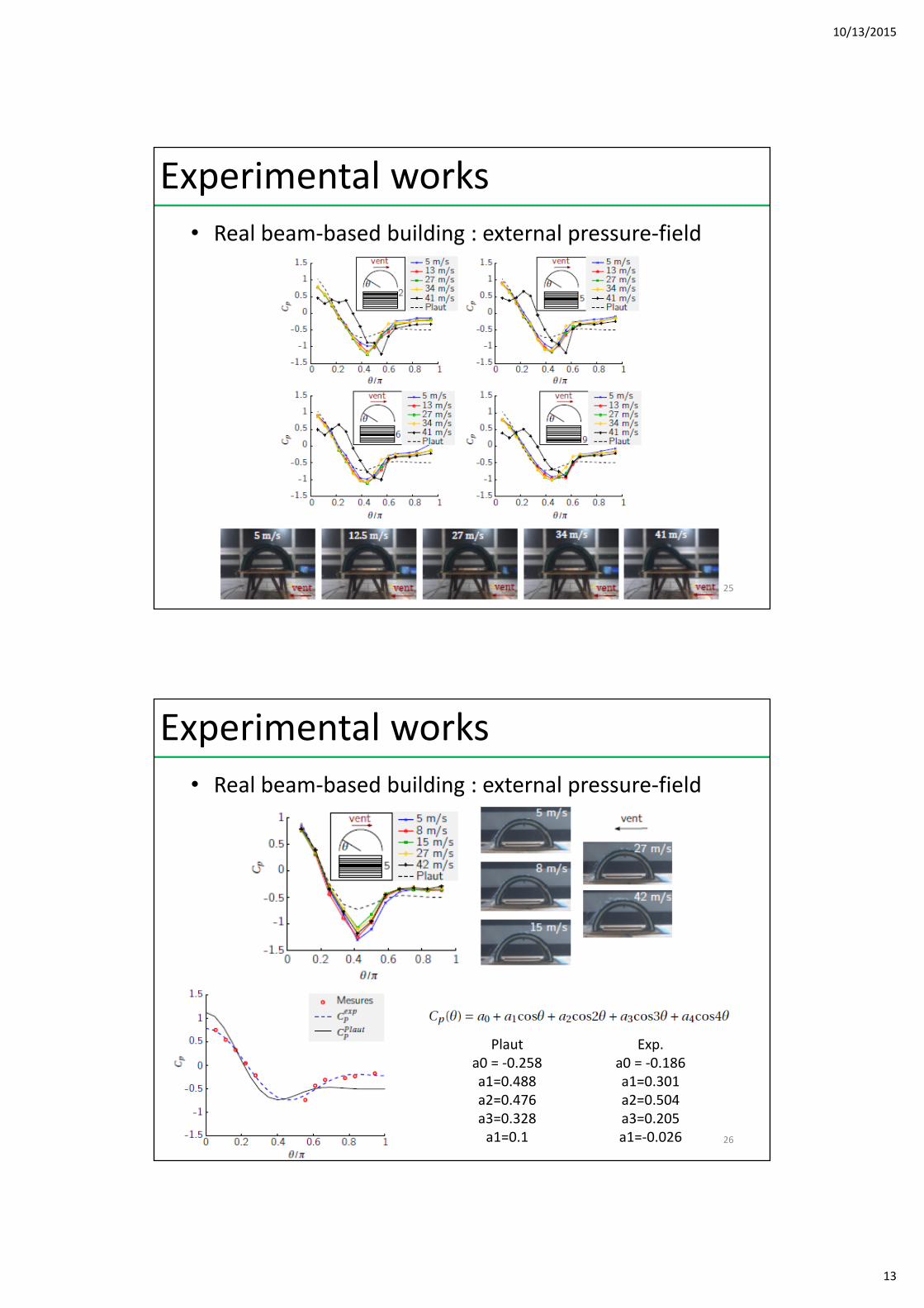
• Real beam‐based building : external pressure‐field
p = 0,03 bar
Experimental works
Plauta0 = ‐0.258a1=0.488a2=0.476a3=0.328a1=0.1
Exp.a0 = ‐0.186a1=0.301a2=0.504a3=0.205a1=‐0.026 26
10/13/2015
14
• Real beam‐based building : global behaviour
Experimental works
27
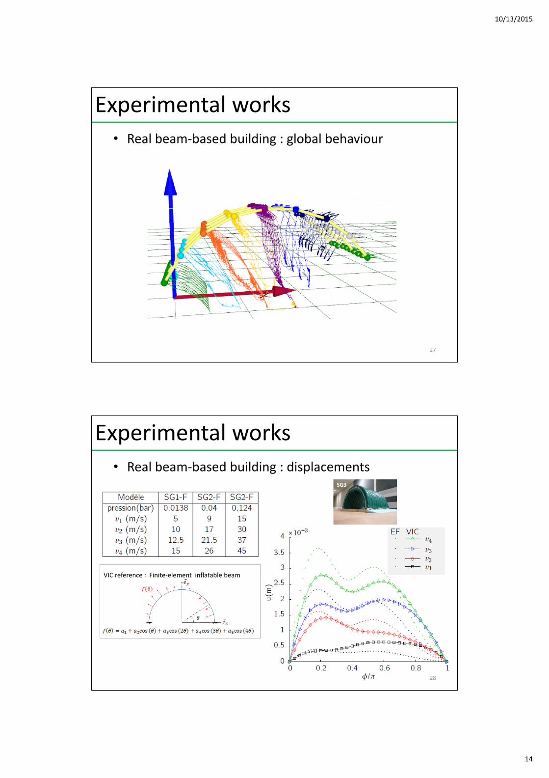
• Real beam‐based building : displacements
p = 0,03 bar
Experimental works
VIC reference : Finite‐element inflatable beam
28
SG3
10/13/2015
15
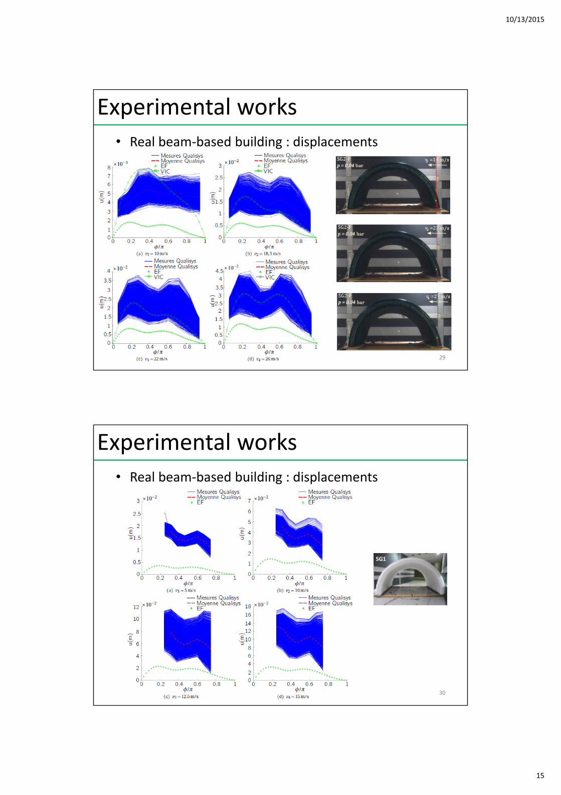
• Real beam‐based building : displacements
Experimental works
29
• Real beam‐based building : displacements
Experimental works
30
SG1
10/13/2015
16
Experimental works
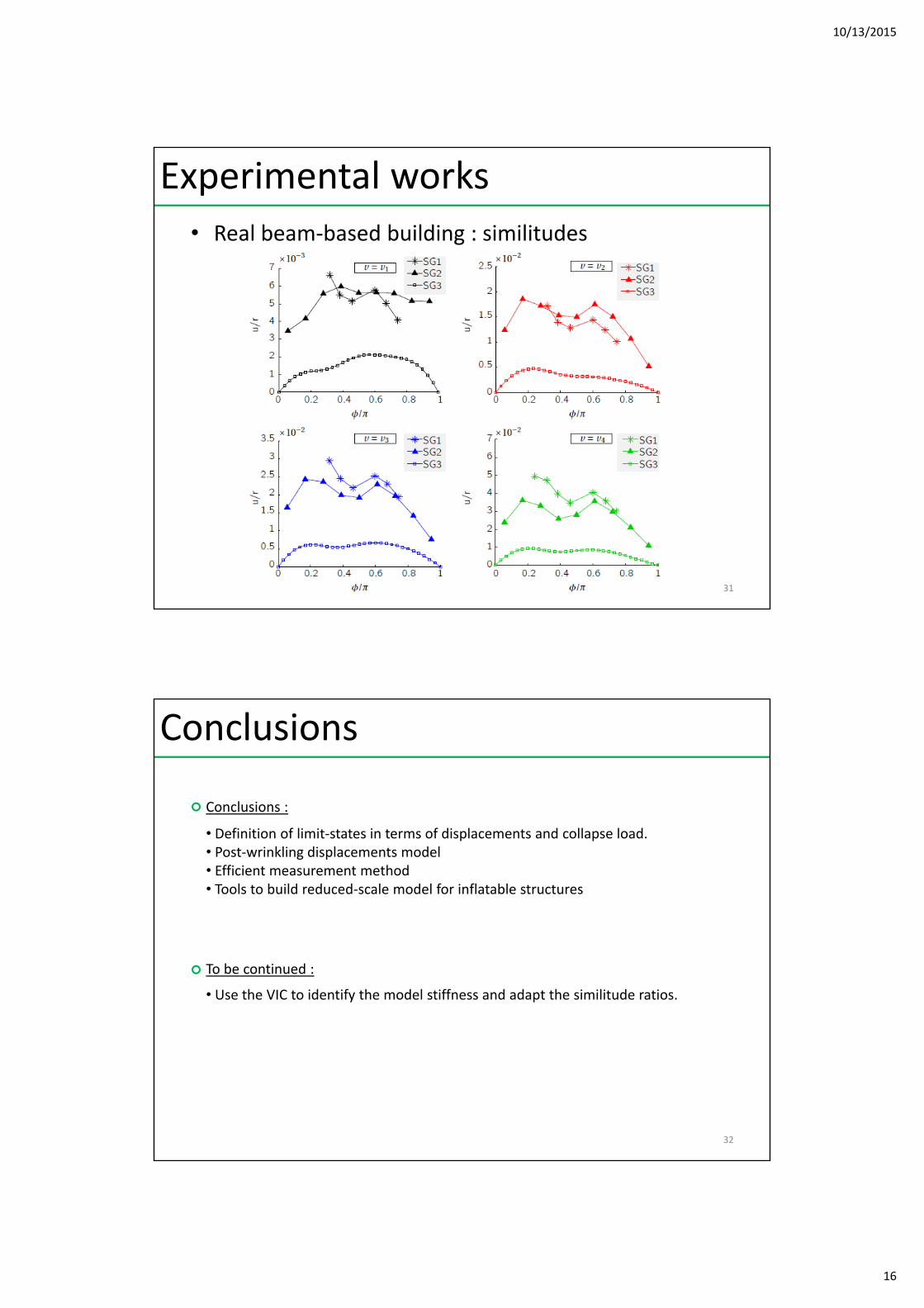
• Real beam‐based building : similitudes
31
• Definition of limit‐states in terms of displacements and collapse load.• Post‐wrinkling displacements model• Efficient measurement method• Tools to build reduced‐scale model for inflatable structures
• Use the VIC to identify the model stiffness and adapt the similitude ratios.
Conclusions :
To be continued :
Conclusions
32
![COST TU1303 SRC4 WG Meeting 2015.03.24-25 · 3. Discussion"and"agreementof"nextacJons"–[MAIN"TOPIC]"to"achieve" TU1303"deliverables" ... Z.A. les Anés, 2 Rue du Chapitre 69126](https://img.pdfslide.us/doc/110x75/5b99206e09d3f2b16c8d11de/cost-tu1303-src4-wg-meeting-20150324-25-3-discussionandagreementofnextacjonsmaintopictoachieve.jpg)