Embed Size (px)
Citation preview
Guide Specification for the Design of Concrete Bridge Beams Prestressed with CFRP Systems
NCHRP 12-97National Cooperative Highway Research Program
Abdeldjelil Belarbi, PhD, [email protected]
AASHTO T-6 (FRP Composites)Spokane, WAJune 13, 2017

1. Introduction
2. Experimental Research Program
3. Analytical Research Program
4. Draft of Design Guide Specifications
5. Draft of Material Specifications
6. Concluding Remarks
2
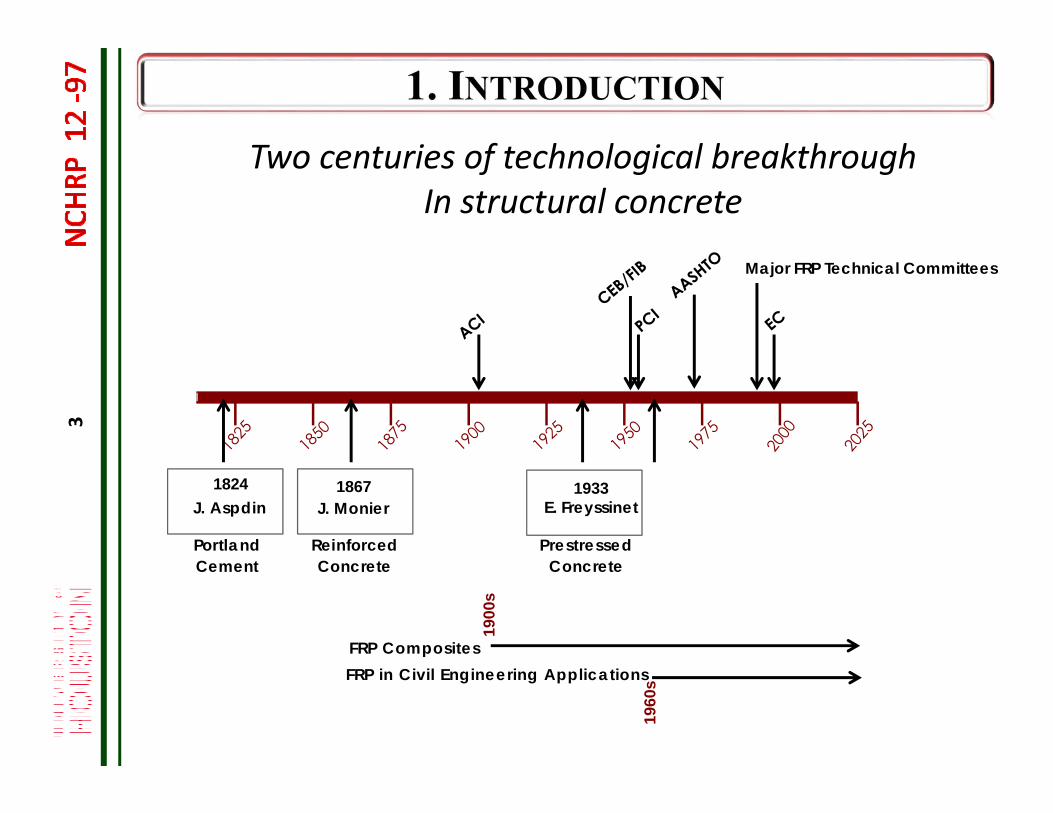
Two centuries of technological breakthroughIn structural concrete
Portland Cement
1824J. Aspdin
1867J. Monier
Reinforced Concrete
1933E. Freyssinet
Prestressed Concrete
FRP CompositesFRP in Civil Engineering Applications
1960
s
1900
s
Major FRP Technical Committees
3
FRPin Bridges, was it a dream or a vision?
Leonhardt (1964) ‐ in his “Prestressed Concrete ‐Design and Construction” stated that Freyssinet first mentioned the use of glass fibers or plastics for prestressing in 1938:
”Some day, glass fibres or plastics will be used as tendons for prestressing. This idea was first mentioned by Freyssinet in 1938. In the U.S.A., investigations are already in progress in this connection...
4
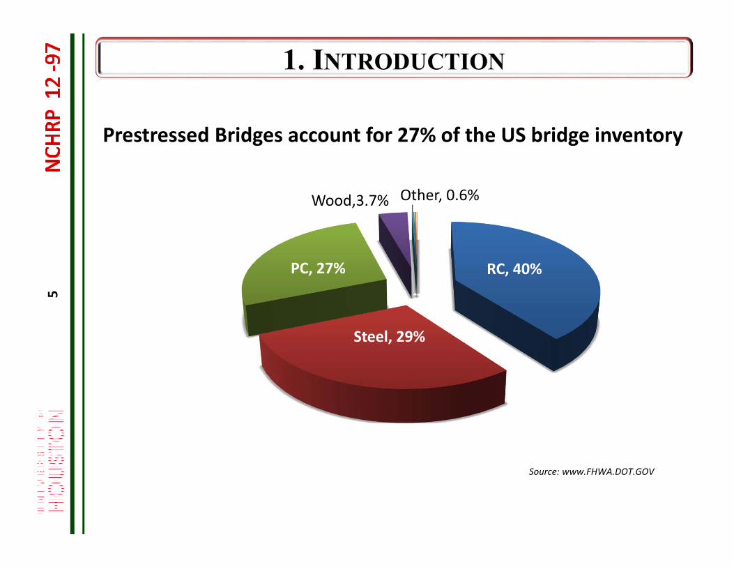
RC, 40%
Steel, 29%
PC, 27%
Wood,3.7% Other, 0.6%
Source: www.FHWA.DOT.GOV
5
Prestressed Bridges account for 27% of the US bridge inventory
6
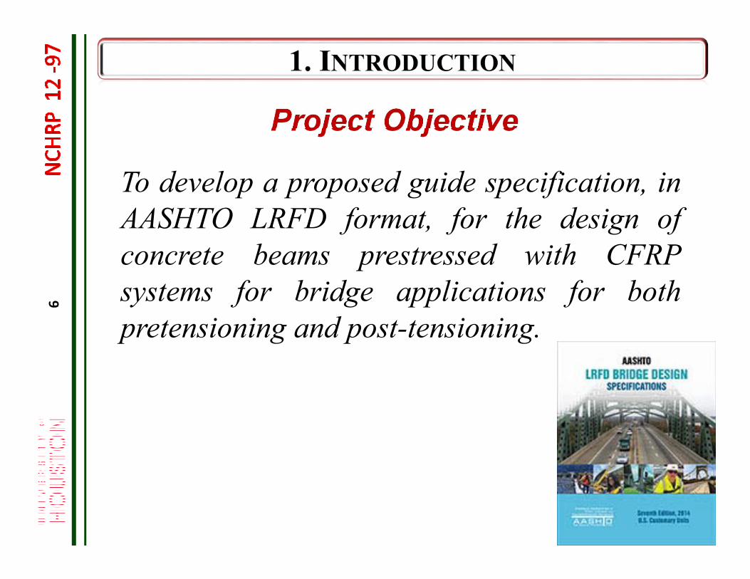
Project Objective
To develop a proposed guide specification, inAASHTO LRFD format, for the design ofconcrete beams prestressed with CFRPsystems for bridge applications for bothpretensioning and post-tensioning.
7
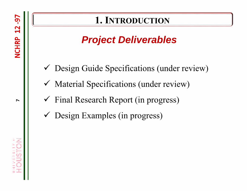
Design Guide Specifications (under review)
Material Specifications (under review)
Final Research Report (in progress)
Design Examples (in progress)
Project Deliverables
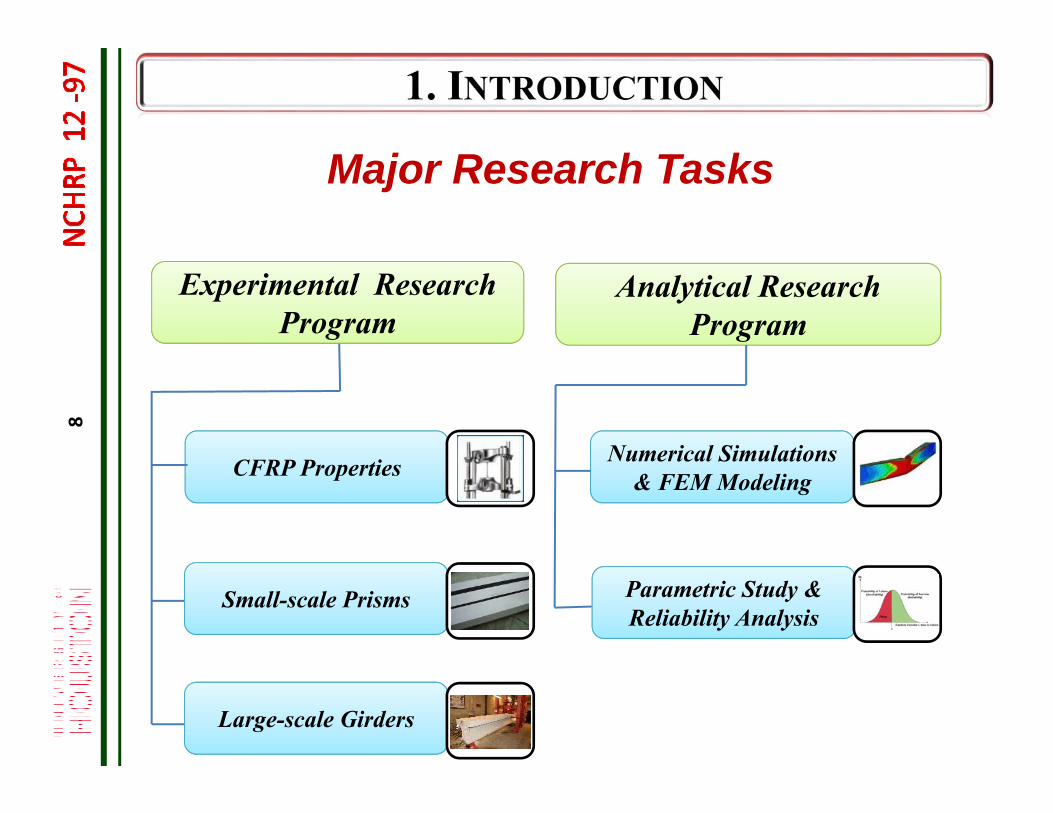
Analytical Research Program
CFRP Properties
Small-scale Prisms
Large-scale Girders
Parametric Study &Reliability Analysis
Major Research Tasks
Experimental Research Program
Numerical Simulations& FEM Modeling
8
9
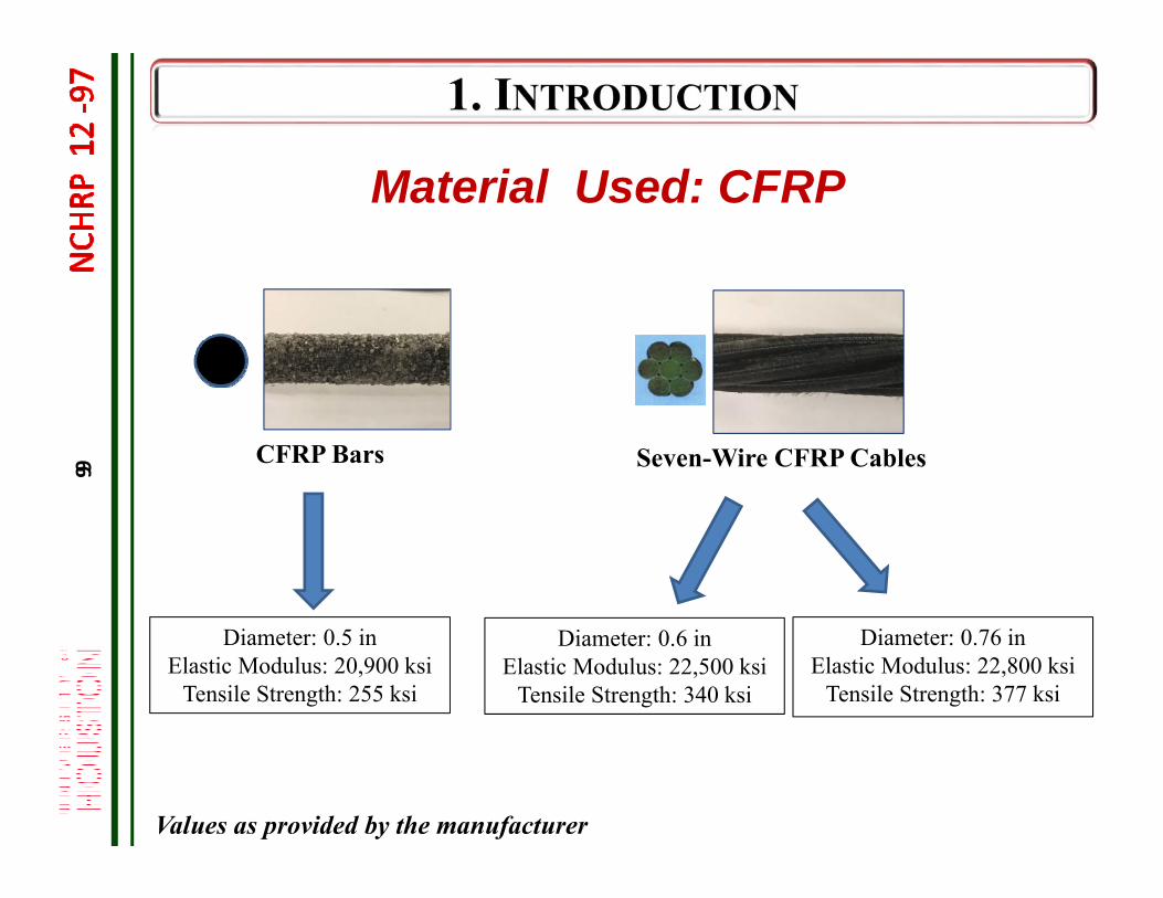
CFRP Bars Seven-Wire CFRP Cables
Diameter: 0.5 inElastic Modulus: 20,900 ksi
Tensile Strength: 255 ksi
Diameter: 0.76 inElastic Modulus: 22,800 ksi
Tensile Strength: 377 ksi
Diameter: 0.6 inElastic Modulus: 22,500 ksi
Tensile Strength: 340 ksi
Values as provided by the manufacturer
Material Used: CFRP
9
10
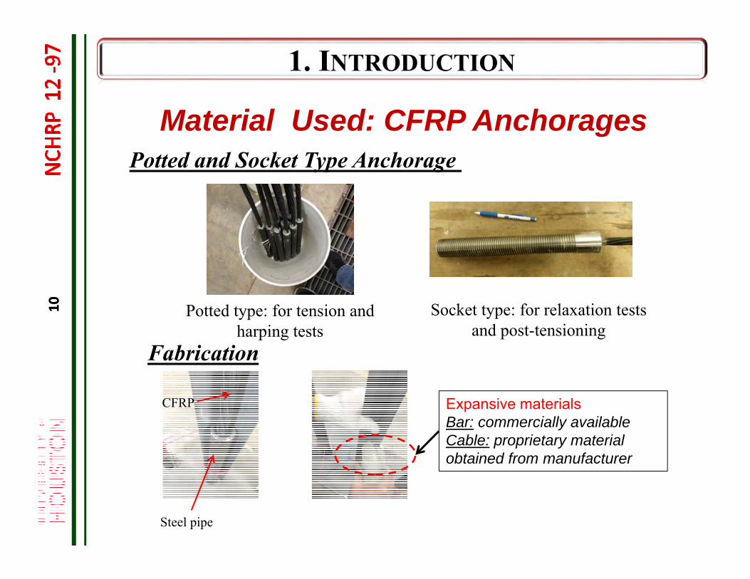
Material Used: CFRP Anchorages
Potted type: for tension and harping tests wedge
Potted and Socket Type Anchorage
Socket type: for relaxation tests and post-tensioning
Expansive materialsBar: commercially availableCable: proprietary material obtained from manufacturer
CFRP
Steel pipe
Fabrication
10
11
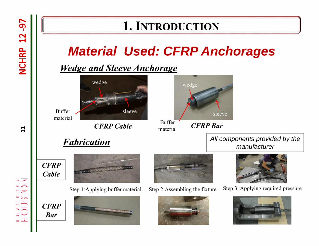
Material Used: CFRP Anchorages
wedge
Wedge and Sleeve Anchorage
Fabrication
CFRP Cable CFRP Bar
wedge
sleeve
wedge
sleeveBuffer material
Buffer material
Step 1:Applying buffer material Step 2:Assembling the fixture Step 3: Applying required pressure
All components provided by the manufacturer
CFRP Bar
CFRP Cable
12
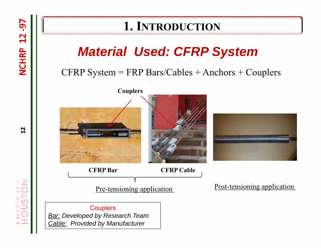
Material Used: CFRP SystemCFRP System = FRP Bars/Cables + Anchors + Couplers
Couplers
CFRP Bar CFRP Cable
CouplersBar: Developed by Research TeamCable: Provided by Manufacturer
Pre-tensioning application Post-tensioning application
12
13
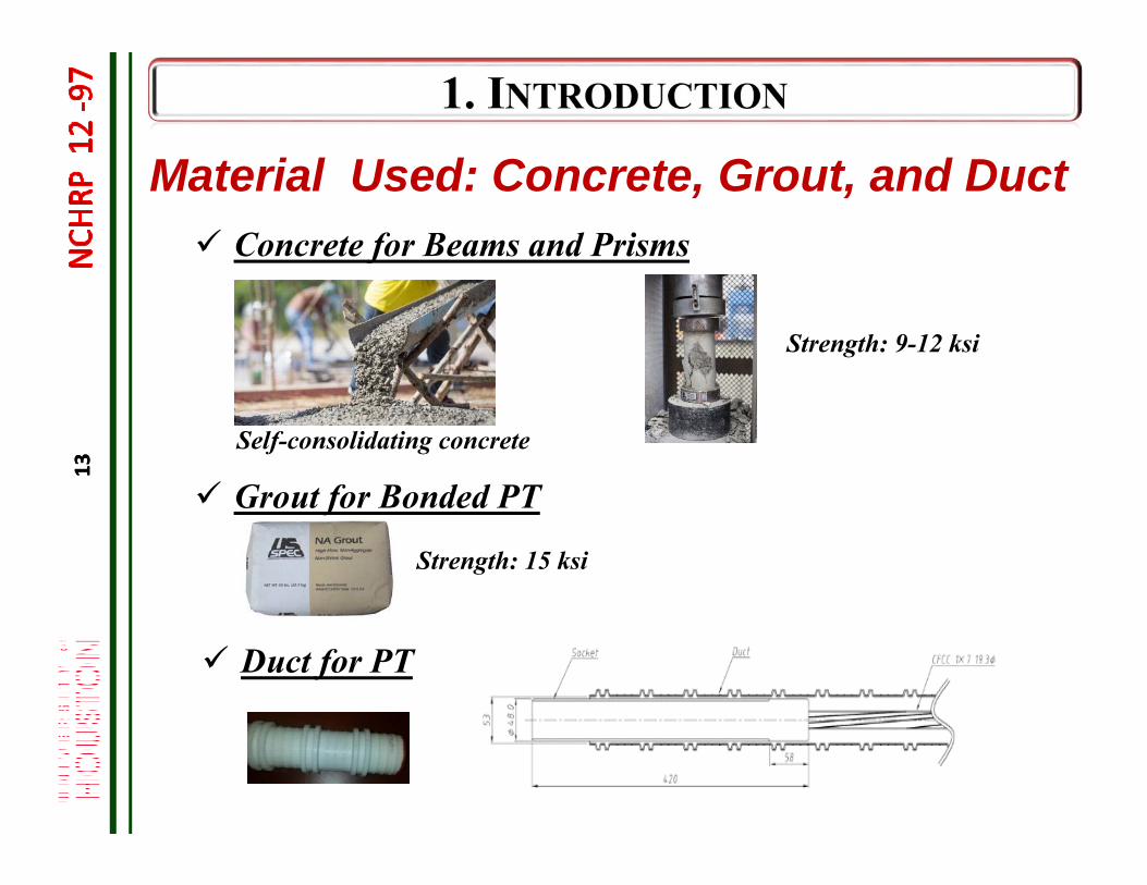
Concrete for Beams and Prisms
Strength: 9-12 ksi
Strength: 15 ksi
Material Used: Concrete, Grout, and Duct
Self-consolidating concrete
Grout for Bonded PT
Duct for PT
13
14
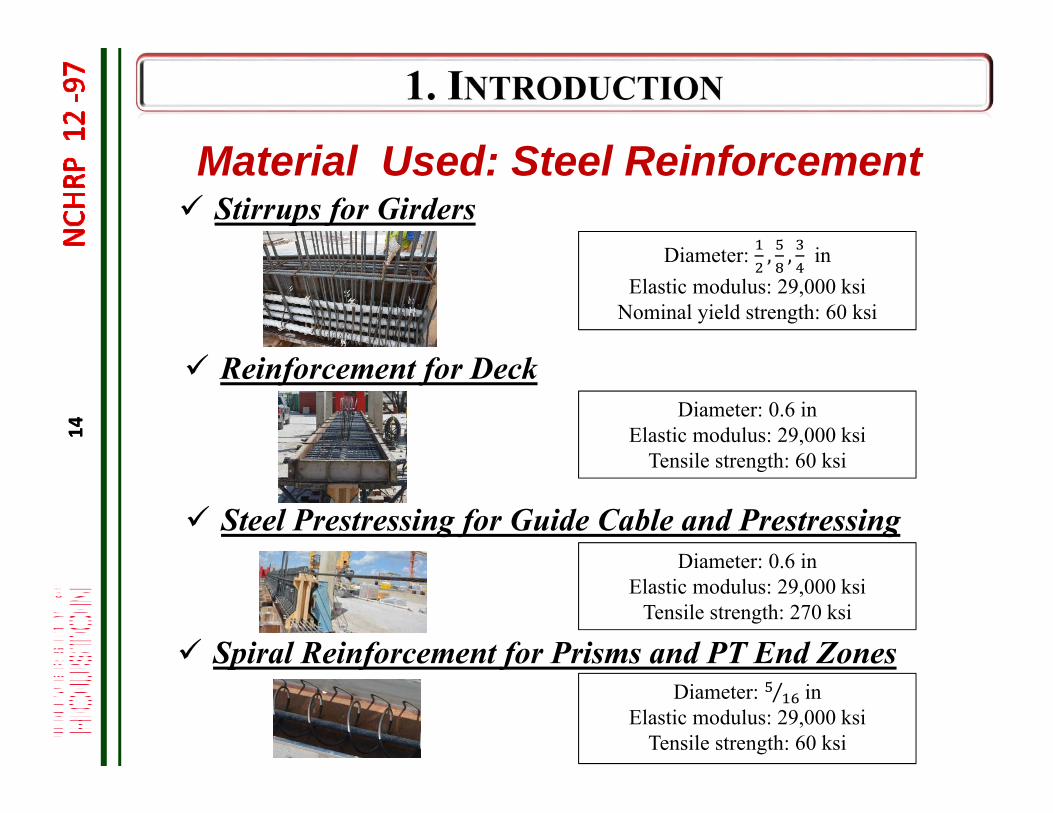
Diameter: 0.6 inElastic modulus: 29,000 ksi
Tensile strength: 60 ksi
Diameter: , , inElastic modulus: 29,000 ksi
Nominal yield strength: 60 ksi
Material Used: Steel Reinforcement Stirrups for Girders
Reinforcement for Deck
Spiral Reinforcement for Prisms and PT End ZonesDiameter: ⁄ in
Elastic modulus: 29,000 ksiTensile strength: 60 ksi
Steel Prestressing for Guide Cable and PrestressingDiameter: 0.6 in
Elastic modulus: 29,000 ksiTensile strength: 270 ksi
14
15
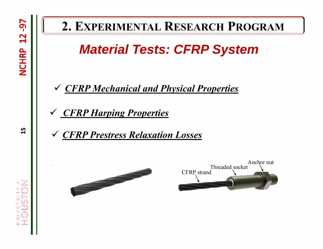
Material Tests: CFRP System
CFRP Mechanical and Physical Properties
CFRP Harping Properties
CFRP Prestress Relaxation Losses15
16
Material Tests: CFRP System
CFRP Mechanical and Physical Properties Cross-Sectional Properties (Af) Fiber Volume Ratio (Vf) Glass-Transition Temperature (Tg) Moisture Absorption Tension Strength, Modulus of Elasticity, Rupture Strain (fpu, Ef,
pu)
Test Procedures Test Results Applicable Design Guide Specifications/Material Specifications
17
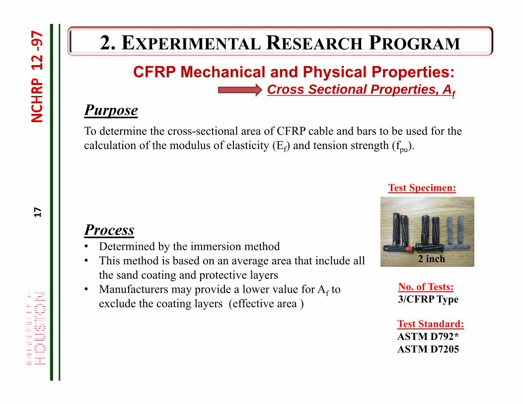
CFRP Mechanical and Physical Properties:Cross Sectional Properties, Af
Purpose
Process• Determined by the immersion method• This method is based on an average area that include all
the sand coating and protective layers• Manufacturers may provide a lower value for Af to
exclude the coating layers (effective area )
Test Specimen:
2 inch
No. of Tests:3/CFRP Type
Test Standard:ASTM D792*ASTM D7205
To determine the cross-sectional area of CFRP cable and bars to be used for the calculation of the modulus of elasticity (Ef) and tension strength (fpu).
18
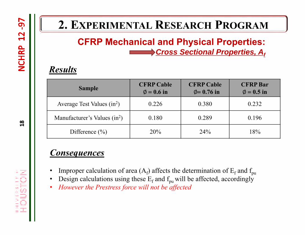
Results
Sample CFRP Cable∅ 0.6 in
CFRP Cable∅0.76 in
CFRP Bar∅ 0.5 in
Average Test Values (in2) 0.226 0.380 0.232
Manufacturer’s Values (in2) 0.180 0.289 0.196
Difference (%) 20% 24% 18%
Consequences
• Improper calculation of area (Af) affects the determination of Ef and fpu• Design calculations using these Ef and fpu will be affected, accordingly • However the Prestress force will not be affected
CFRP Mechanical and Physical Properties:Cross Sectional Properties, Af
18
19
AASHTO Material Specifications (Draft)
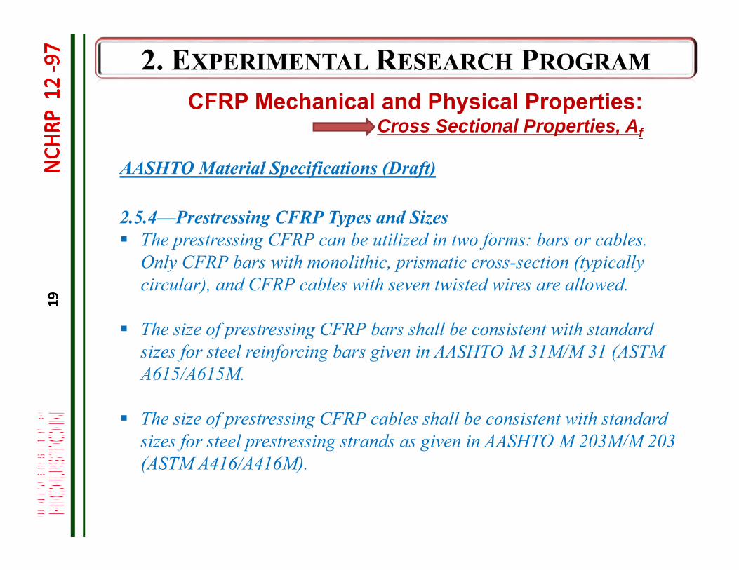
2.5.4—Prestressing CFRP Types and Sizes The prestressing CFRP can be utilized in two forms: bars or cables.
Only CFRP bars with monolithic, prismatic cross-section (typically circular), and CFRP cables with seven twisted wires are allowed.
The size of prestressing CFRP bars shall be consistent with standard sizes for steel reinforcing bars given in AASHTO M 31M/M 31 (ASTM A615/A615M.
The size of prestressing CFRP cables shall be consistent with standard sizes for steel prestressing strands as given in AASHTO M 203M/M 203 (ASTM A416/A416M).
CFRP Mechanical and Physical Properties:Cross Sectional Properties, Af
19
20
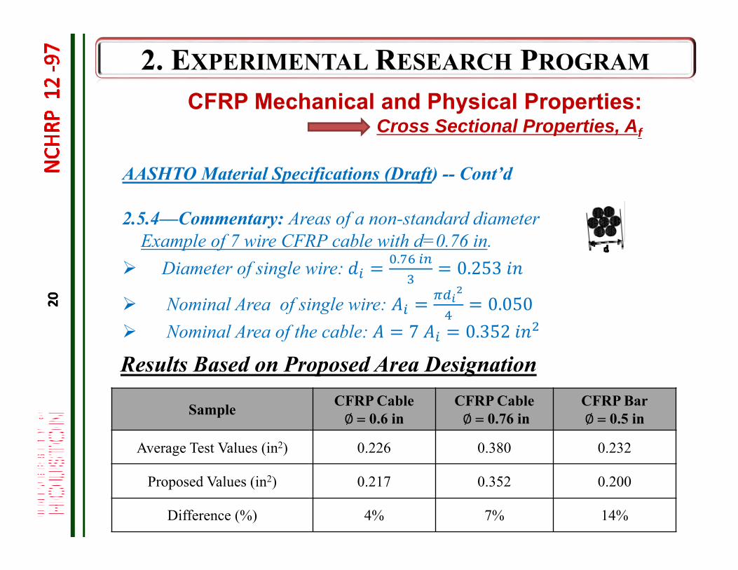
Results Based on Proposed Area Designation
AASHTO Material Specifications (Draft) -- Cont’d
2.5.4—Commentary: Areas of a non-standard diameter Example of 7 wire CFRP cable with d=0.76 in.
Diameter of single wire: . 0.253
Nominal Area of single wire: 0.050 Nominal Area of the cable: 7 0.352
Sample CFRP Cable∅ 0.6 in
CFRP Cable∅ 0.76 in
CFRP Bar∅ 0.5 in
Average Test Values (in2) 0.226 0.380 0.232
Proposed Values (in2) 0.217 0.352 0.200
Difference (%) 4% 7% 14%
CFRP Mechanical and Physical Properties:Cross Sectional Properties, Af
20
21
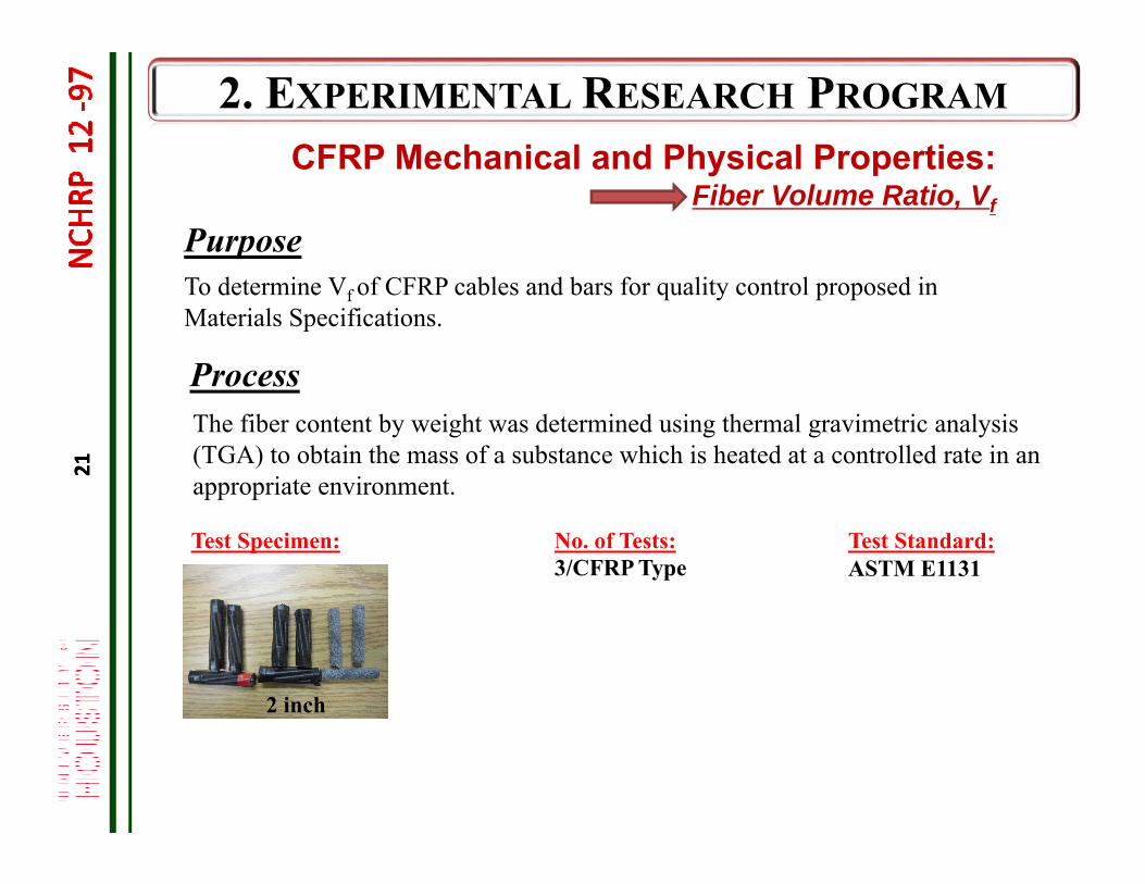
Purpose
Process
Test Specimen: No. of Tests:3/CFRP Type
Test Standard:ASTM E1131
To determine Vf of CFRP cables and bars for quality control proposed in Materials Specifications.
2 inch
The fiber content by weight was determined using thermal gravimetric analysis (TGA) to obtain the mass of a substance which is heated at a controlled rate in an appropriate environment.
CFRP Mechanical and Physical Properties:Fiber Volume Ratio, Vf
21
22
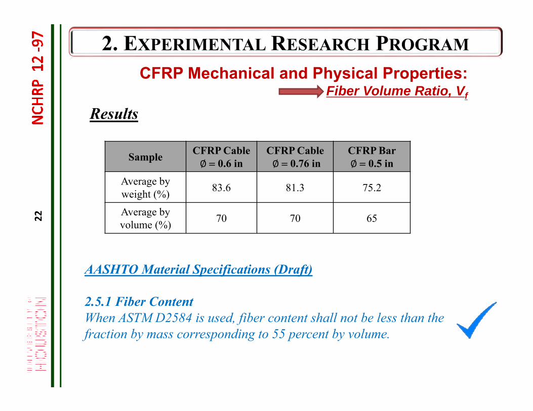
Results
AASHTO Material Specifications (Draft)
2.5.1 Fiber ContentWhen ASTM D2584 is used, fiber content shall not be less than the fraction by mass corresponding to 55 percent by volume.
Sample CFRP Cable∅ 0.6 in
CFRP Cable∅ 0.76 in
CFRP Bar∅ 0.5 in
Average by weight (%) 83.6 81.3 75.2
Average by volume (%) 70 70 65
CFRP Mechanical and Physical Properties:Fiber Volume Ratio, Vf
23
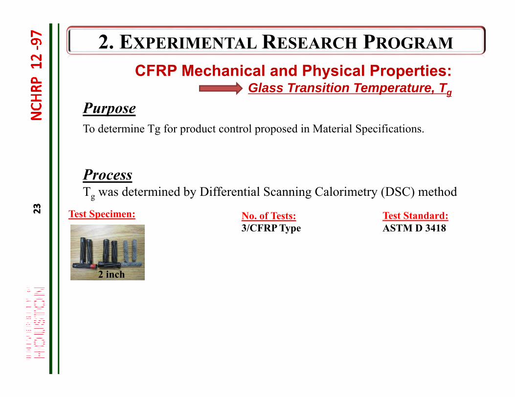
Purpose
ProcessTg was determined by Differential Scanning Calorimetry (DSC) method
To determine Tg for product control proposed in Material Specifications.
Test Specimen: No. of Tests:3/CFRP Type
Test Standard:ASTM D 3418
2 inch
CFRP Mechanical and Physical Properties:Glass Transition Temperature, Tg
23
24
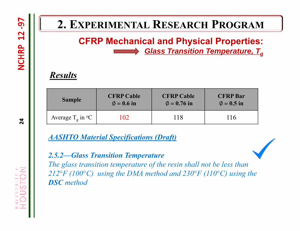
Results
AASHTO Material Specifications (Draft)
2.5.2—Glass Transition TemperatureThe glass transition temperature of the resin shall not be less than 212°F (100°C) using the DMA method and 230°F (110°C) using the DSC method
Sample CFRP Cable∅ 0.6 in
CFRP Cable∅ 0.76 in
CFRP Bar∅ 0.5 in
Average Tg in oC 102 118 116
CFRP Mechanical and Physical Properties:Glass Transition Temperature, Tg
24
25
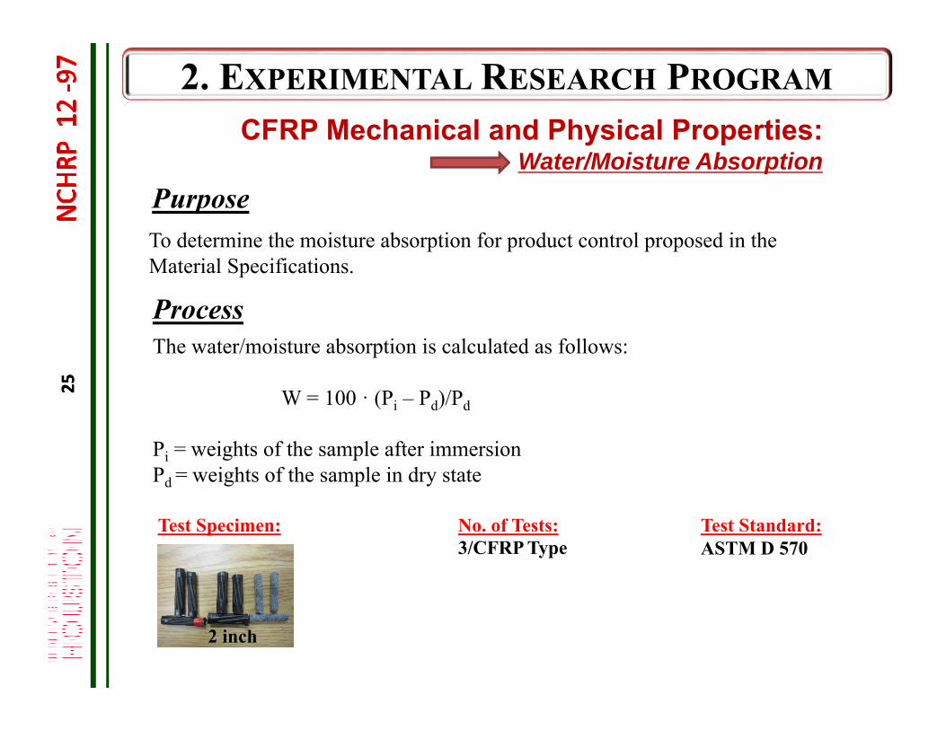
Purpose
ProcessThe water/moisture absorption is calculated as follows:
W = 100 · (Pi – Pd)/Pd
Pi = weights of the sample after immersion Pd = weights of the sample in dry state
To determine the moisture absorption for product control proposed in the Material Specifications.
Test Specimen: No. of Tests:3/CFRP Type
Test Standard:ASTM D 570
CFRP Mechanical and Physical Properties:Water/Moisture Absorption
2 inch
25
26
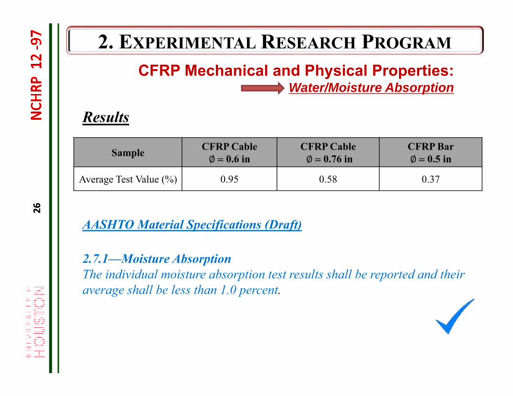
Results
Sample CFRP Cable∅ 0.6 in
CFRP Cable∅ 0.76 in
CFRP Bar∅ 0.5 in
Average Test Value (%) 0.95 0.58 0.37
AASHTO Material Specifications (Draft)
2.7.1—Moisture AbsorptionThe individual moisture absorption test results shall be reported and their average shall be less than 1.0 percent.
CFRP Mechanical and Physical Properties:Water/Moisture Absorption
26
27
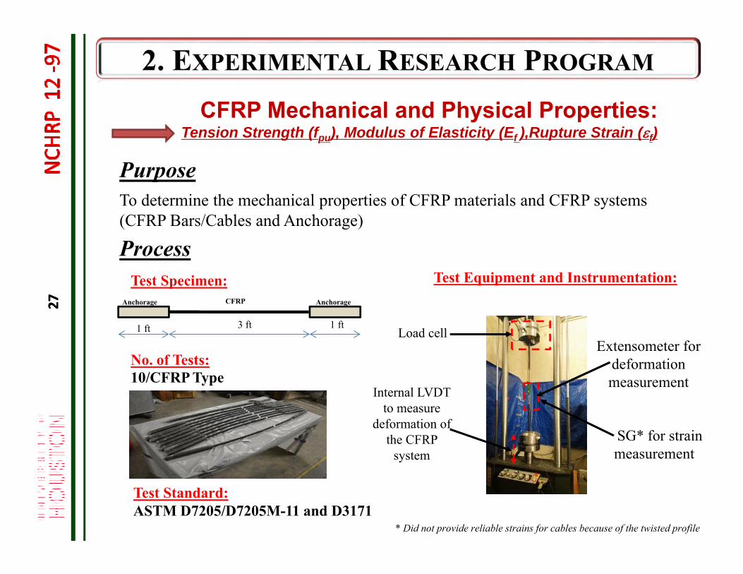
PurposeTo determine the mechanical properties of CFRP materials and CFRP systems (CFRP Bars/Cables and Anchorage)
Process
Extensometer for deformation measurement
SG* for strain measurement
Load cell
Test Standard:ASTM D7205/D7205M-11 and D3171
3 ft 1 ft1 ft
AnchorageAnchorage CFRP
Test Specimen:
No. of Tests:10/CFRP Type
Test Equipment and Instrumentation:
Internal LVDT to measure
deformation of the CFRP
system
* Did not provide reliable strains for cables because of the twisted profile
CFRP Mechanical and Physical Properties:Tension Strength (fpu), Modulus of Elasticity (Ef ),Rupture Strain (f)
27
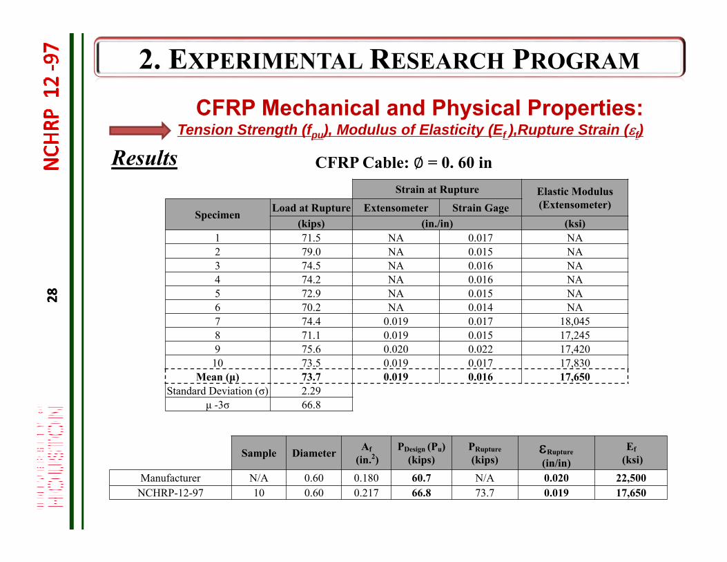
28
Strain at Rupture Elastic Modulus (Extensometer)
Specimen Load at Rupture Extensometer Strain Gage(kips) (in./in) (ksi)
1 71.5 NA 0.017 NA2 79.0 NA 0.015 NA3 74.5 NA 0.016 NA4 74.2 NA 0.016 NA5 72.9 NA 0.015 NA6 70.2 NA 0.014 NA7 74.4 0.019 0.017 18,0458 71.1 0.019 0.015 17,2459 75.6 0.020 0.022 17,42010 73.5 0.019 0.017 17,830
Mean (μ) 73.7 0.019 0.016 17,650Standard Deviation (σ) 2.29
μ -3σ 66.8
Sample Diameter Af(in.2)
PDesign (Pu)(kips)
PRupture(kips)
Rupture
(in/in)Ef
(ksi)
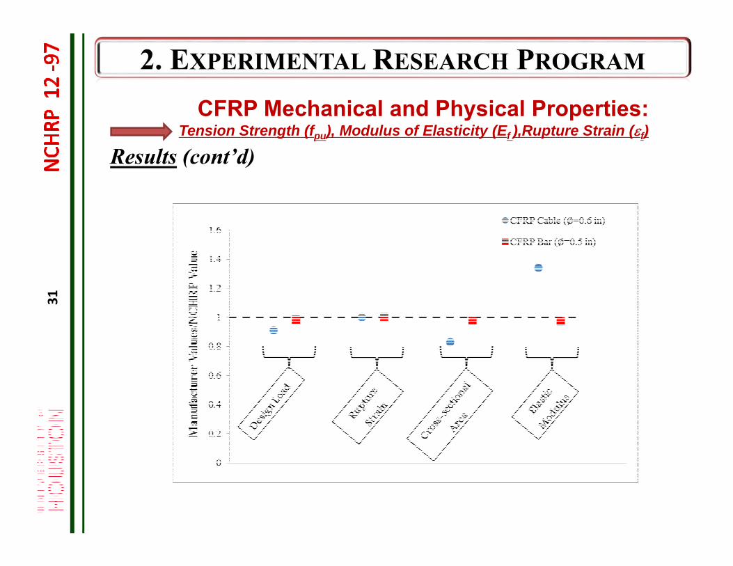
Manufacturer N/A 0.60 0.180 60.7 N/A 0.020 22,500NCHRP-12-97 10 0.60 0.217 66.8 73.7 0.019 17,650
Results
CFRP Mechanical and Physical Properties:Tension Strength (fpu), Modulus of Elasticity (Ef ),Rupture Strain (f)
CFRP Cable: ∅ = 0. 60 in
28
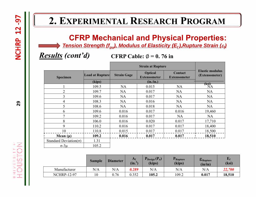
29
Strain at RuptureElastic modulus (Extensometer) Specimen Load at Rupture Strain Gage Optical
ExtensometerContact
Extensometer(kips) (in./in.)
1 109.5 NA 0.015 NA NA2 109.7 NA 0.017 NA NA3 109.6 NA 0.017 NA NA4 108.3 NA 0.016 NA NA5 108.6 NA 0.018 NA NA6 109.6 0.016 0.017 0.016 19,4607 109.2 0.016 0.017 NA NA8 106.0 0.016 0.020 0.017 17,7109 110.2 0.016 0.017 0.017 18,40010 110.8 0.015 0.017 0.017 18,500
Mean (μ) 109.2 0.016 0.017 0.017 18,510Standard Deviation(σ) 1.31
σ-3μ 105.2
CFRP Mechanical and Physical Properties:Tension Strength (fpu), Modulus of Elasticity (Ef ),Rupture Strain (f)
Results (cont’d) CFRP Cable: ∅ = 0. 76 in
Sample Diameter Af(in.2)
PDesign (Pu)(kips)
PRupture(kips)
Rupture
(in/in)Ef
(ksi)
Manufacturer N/A N/A 0.289 N/A N/A N/A 22,700NCHRP-12-97 10 0.76 0.352 105.2 109.2 0.017 18,510
(ksi)
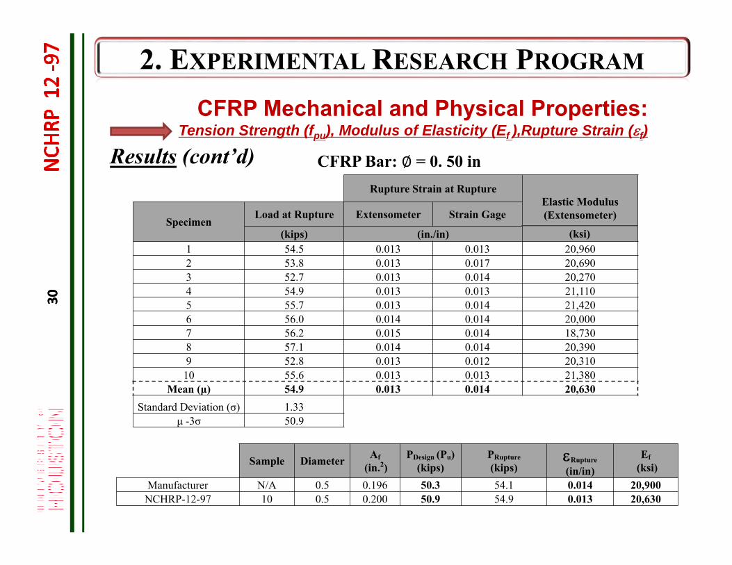
30
Rupture Strain at RuptureElastic Modulus(Extensometer) Specimen
Load at Rupture Extensometer Strain Gage
(kips) (in./in)1 54.5 0.013 0.013 20,9602 53.8 0.013 0.017 20,6903 52.7 0.013 0.014 20,2704 54.9 0.013 0.013 21,1105 55.7 0.013 0.014 21,4206 56.0 0.014 0.014 20,0007 56.2 0.015 0.014 18,7308 57.1 0.014 0.014 20,3909 52.8 0.013 0.012 20,31010 55.6 0.013 0.013 21,380
Mean (μ) 54.9 0.013 0.014 20,630Standard Deviation (σ) 1.33
μ -3σ 50.9
CFRP Mechanical and Physical Properties:Tension Strength (fpu), Modulus of Elasticity (Ef ),Rupture Strain (f)
Sample Diameter Af(in.2)
PDesign (Pu)(kips)
PRupture(kips)
Rupture
(in/in)Ef
(ksi)Manufacturer N/A 0.5 0.196 50.3 54.1 0.014 20,900
NCHRP-12-97 10 0.5 0.200 50.9 54.9 0.013 20,630
CFRP Bar: ∅ = 0. 50 inResults (cont’d)
(ksi)
30
31
CFRP Mechanical and Physical Properties:Tension Strength (fpu), Modulus of Elasticity (Ef ),Rupture Strain (f)
Results (cont’d)
32
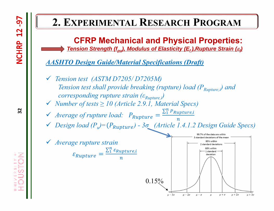
CFRP Mechanical and Physical Properties:Tension Strength (fpu), Modulus of Elasticity (Ef ),Rupture Strain (f)
AASHTO Design Guide/Material Specifications (Draft)
Tension test (ASTM D7205/ D7205M)Tension test shall provide breaking (rupture) load (PRupture,i) and corresponding rupture strain (εRupture,i)
Number of tests ≥ 10 (Article 2.9.1, Material Specs)
Average of rupture load: ∑ ,
Design load (Pu)= ) - 3σ (Article 1.4.1.2 Design Guide Specs)
Average rupture strain∑ ,
0.15%
33
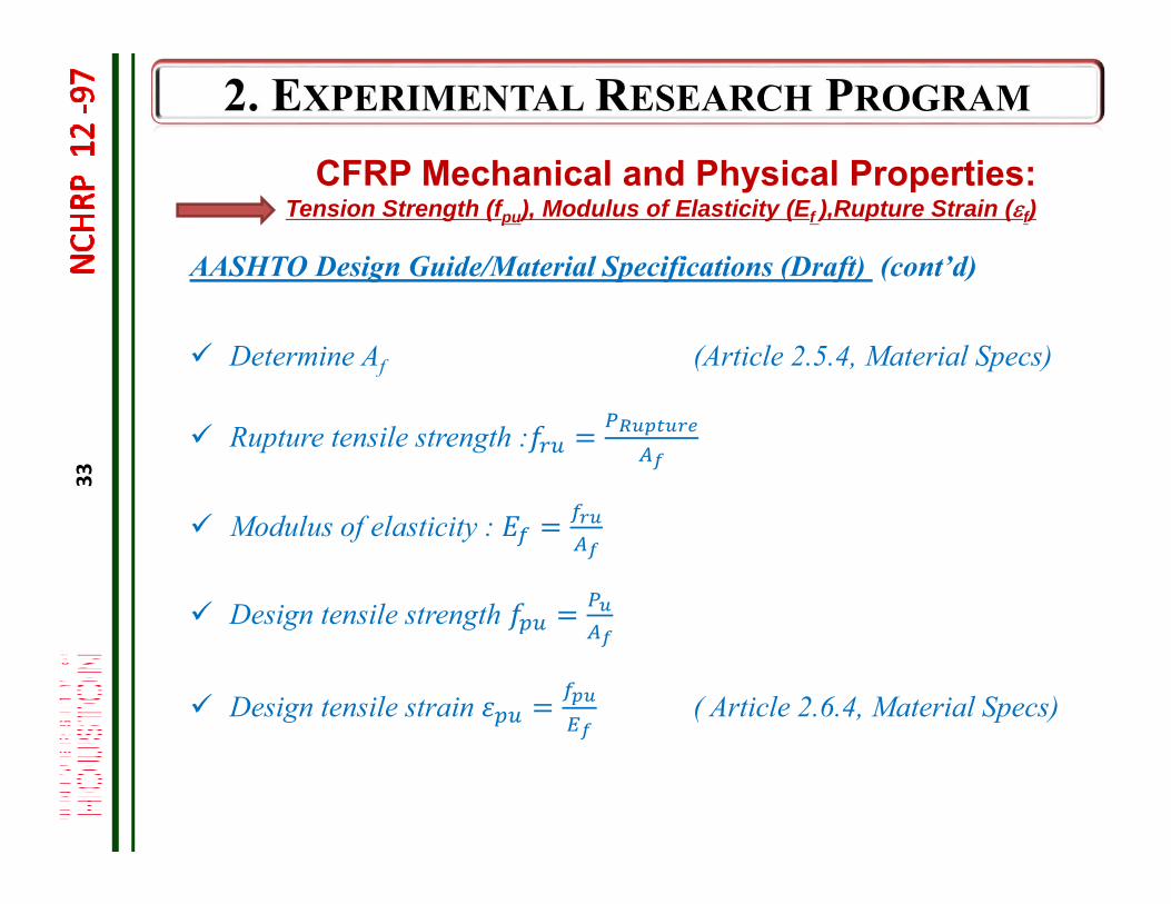
CFRP Mechanical and Physical Properties:Tension Strength (fpu), Modulus of Elasticity (Ef ),Rupture Strain (f)
AASHTO Design Guide/Material Specifications (Draft) (cont’d)
Determine Af (Article 2.5.4, Material Specs)
Rupture tensile strength :
Modulus of elasticity :
Design tensile strength
Design tensile strain ( Article 2.6.4, Material Specs)
34
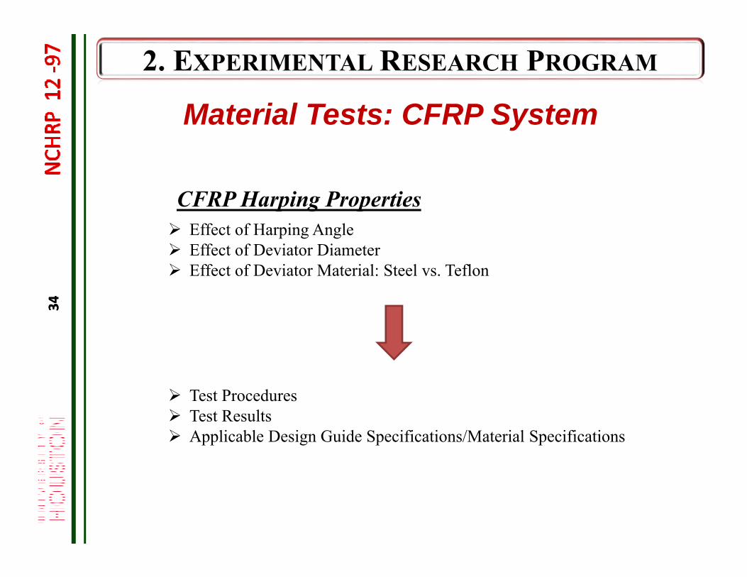
Material Tests: CFRP System
CFRP Harping Properties Effect of Harping Angle Effect of Deviator Diameter Effect of Deviator Material: Steel vs. Teflon
Test Procedures Test Results Applicable Design Guide Specifications/Material Specifications
34
35
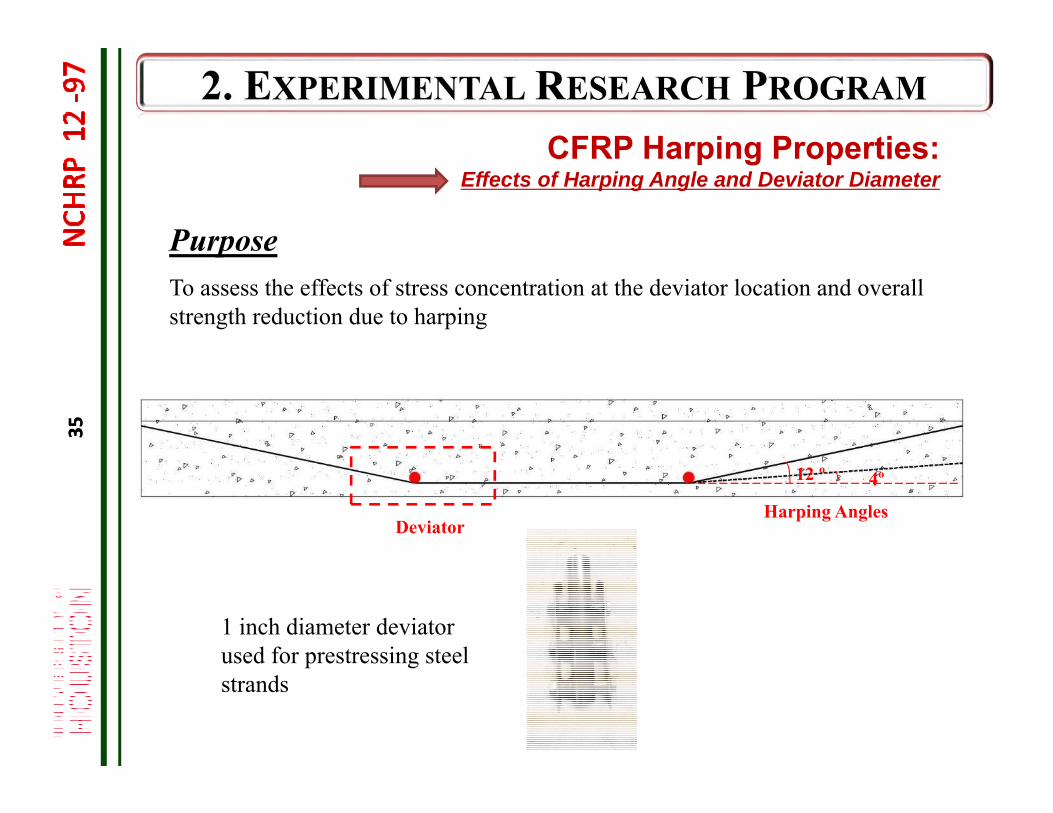
DeviatorHarping Angles
PurposeTo assess the effects of stress concentration at the deviator location and overall strength reduction due to harping
4º12 º
1 inch diameter deviator used for prestressing steel strands
CFRP Harping Properties:Effects of Harping Angle and Deviator Diameter
35
36
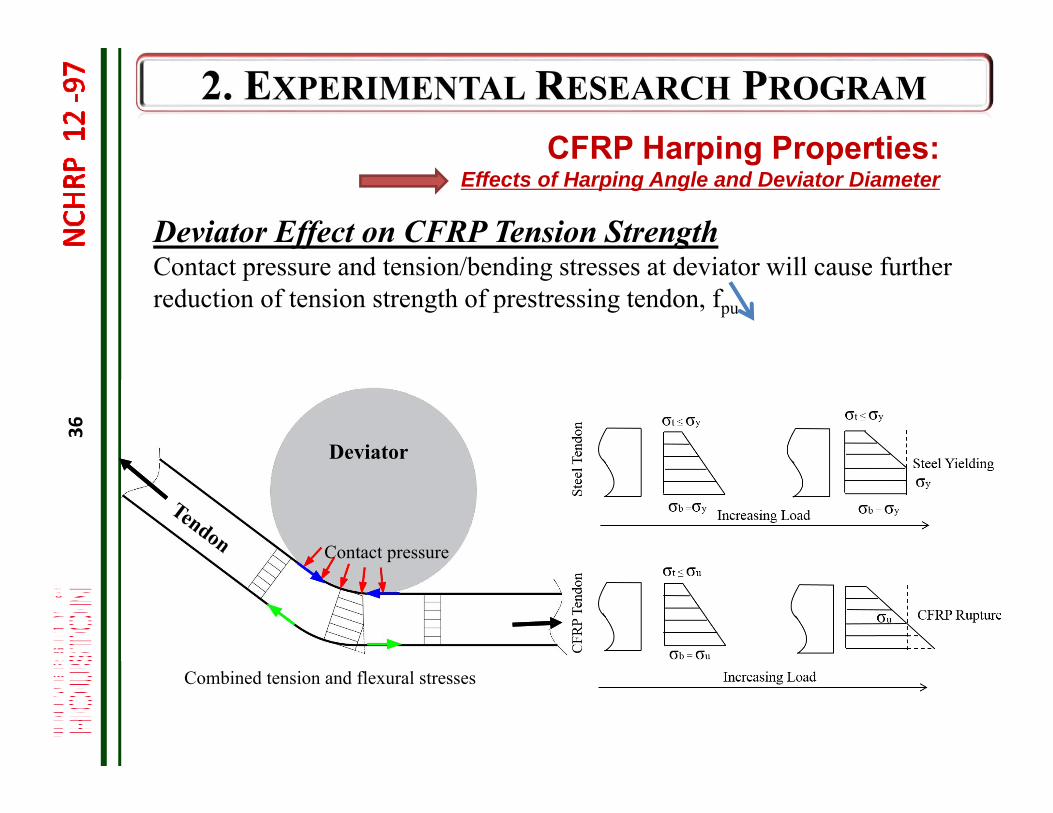
Deviator Effect on CFRP Tension StrengthContact pressure and tension/bending stresses at deviator will cause further reduction of tension strength of prestressing tendon, fpu
Deviator
Combined tension and flexural stresses
Contact pressure
CFRP Harping Properties:Effects of Harping Angle and Deviator Diameter
37
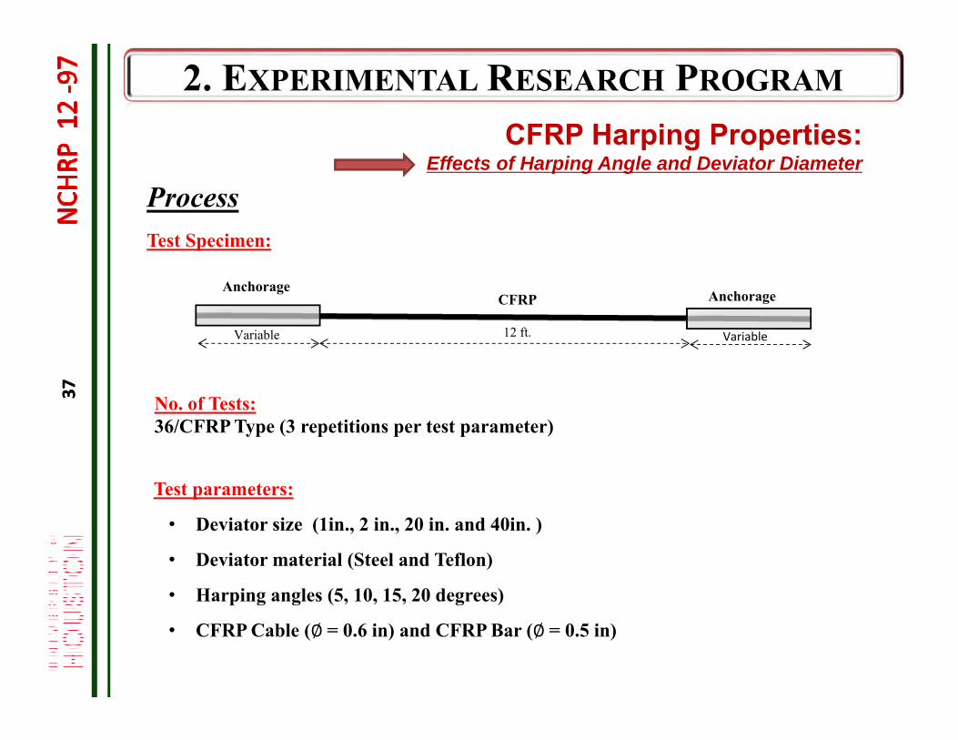
Test parameters:
• Deviator size (1in., 2 in., 20 in. and 40in. )
• Deviator material (Steel and Teflon)
• Harping angles (5, 10, 15, 20 degrees)
• CFRP Cable (∅= 0.6 in) and CFRP Bar (∅= 0.5 in)
ProcessTest Specimen:
No. of Tests:36/CFRP Type (3 repetitions per test parameter)
12 ft. VariableVariable
AnchorageAnchorage
CFRP
CFRP Harping Properties:Effects of Harping Angle and Deviator Diameter
37
38
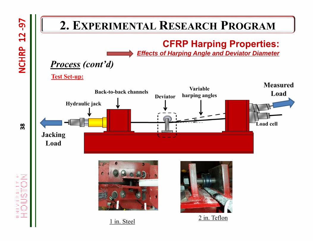
Variable harping anglesDeviator
Hydraulic jack
Back-to-back channels
Load cell
Test Set-up:
Process (cont’d)
Jacking Load
Measured Load
2 in. Teflon1 in. Steel
38
CFRP Harping Properties:Effects of Harping Angle and Deviator Diameter
39
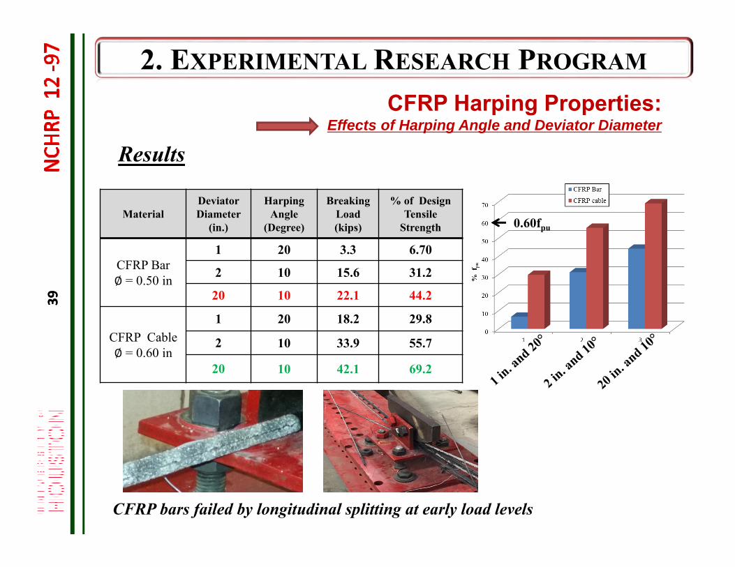
Results
CFRP Harping Properties:Effects of Harping Angle and Deviator Diameter
MaterialDeviator Diameter
(in.)
Harping Angle
(Degree)
Breaking Load (kips)
% of Design Tensile
Strength
CFRP Bar∅ = 0.50 in
1 20 3.3 6.70
2 10 15.6 31.2
20 10 22.1 44.2
CFRP Cable∅ = 0.60 in
1 20 18.2 29.8
2 10 33.9 55.7
20 10 42.1 69.2
CFRP bars failed by longitudinal splitting at early load levels
0.60fpu
39
40
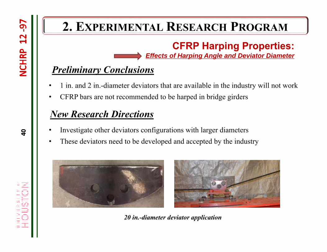
CFRP Harping Properties:Effects of Harping Angle and Deviator Diameter
Preliminary Conclusions• 1 in. and 2 in.-diameter deviators that are available in the industry will not work• CFRP bars are not recommended to be harped in bridge girders
New Research Directions• Investigate other deviators configurations with larger diameters• These deviators need to be developed and accepted by the industry
20 in.-diameter deviator application
40
41
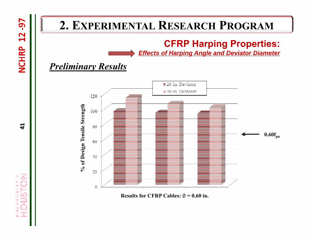
CFRP Harping Properties:Effects of Harping Angle and Deviator Diameter
Preliminary Results%
of D
esig
n Te
nsile
Str
engt
h
0.60fpu
Results for CFRP Cables: ∅ = 0.60 in.
41
42
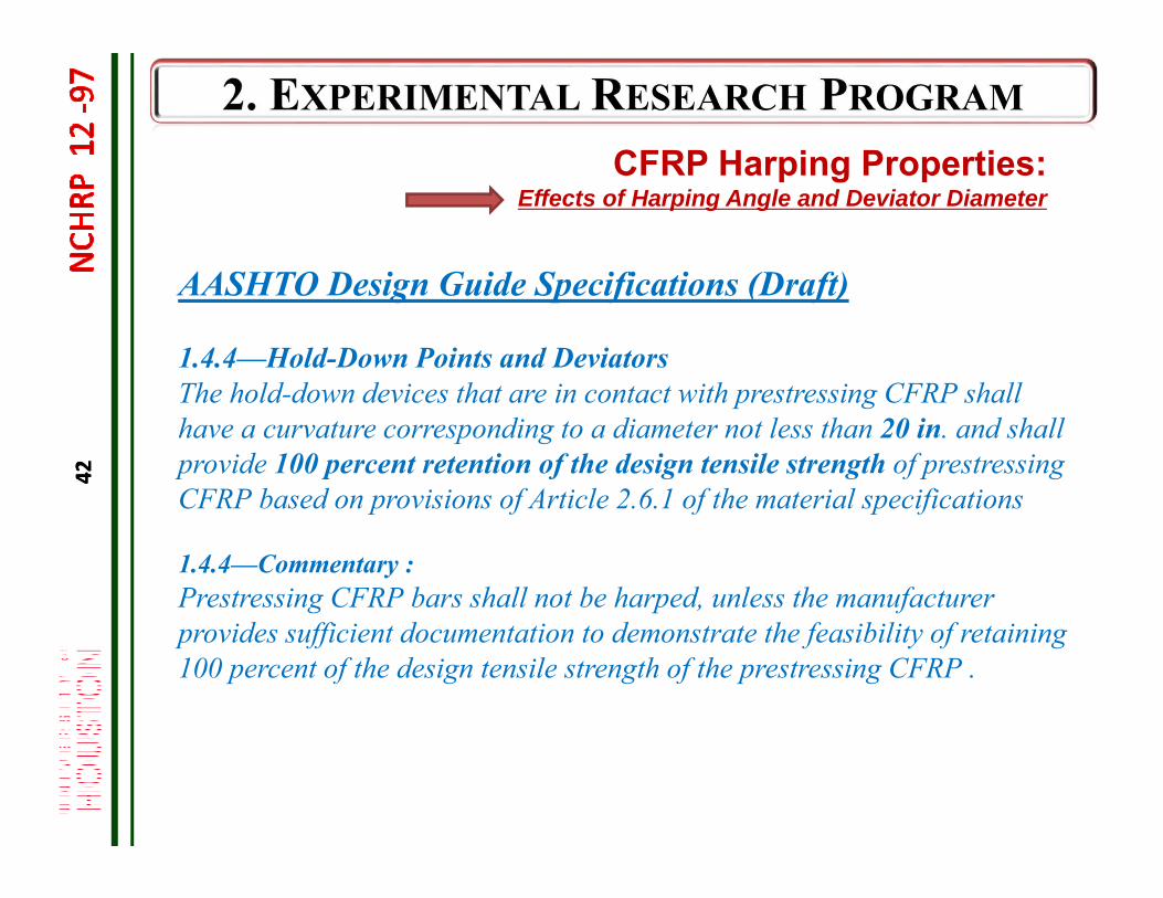
AASHTO Design Guide Specifications (Draft)
1.4.4—Hold-Down Points and DeviatorsThe hold-down devices that are in contact with prestressing CFRP shall have a curvature corresponding to a diameter not less than 20 in. and shall provide 100 percent retention of the design tensile strength of prestressing CFRP based on provisions of Article 2.6.1 of the material specifications
1.4.4—Commentary :Prestressing CFRP bars shall not be harped, unless the manufacturer provides sufficient documentation to demonstrate the feasibility of retaining 100 percent of the design tensile strength of the prestressing CFRP .
CFRP Harping Properties:Effects of Harping Angle and Deviator Diameter
42
43
AASHTO Design Guide Specifications (Draft) (cont’d)
1.9.1.1—Prestressing CFRPs with Angle Points or Curves
On-Going Task
CFRP Harping Properties:Effects of Harping Angle and Deviator Diameter
43
44
Material Tests: CFRP System
CFRP Prestress Relaxation Losses Prestress Relaxation Losses of CFRP Bars and Cables Prestress Relaxation Losses of CFRP System (Bars/Cables and Anchorages) Effect of Jacking Stress level Effect of Bars/Cables Lengths
Test Procedures Test Results Applicable Design Guide Specifications/Material Specifications
44
45
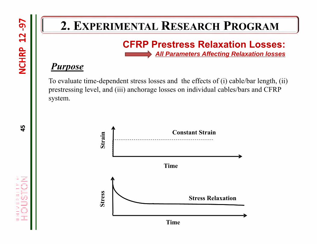
PurposeTo evaluate time-dependent stress losses and the effects of (i) cable/bar length, (ii) prestressing level, and (iii) anchorage losses on individual cables/bars and CFRP system.
Stre
ssSt
rain
Stress Relaxation
Constant Strain
Time
Time
CFRP Prestress Relaxation Losses:All Parameters Affecting Relaxation losses
45
46
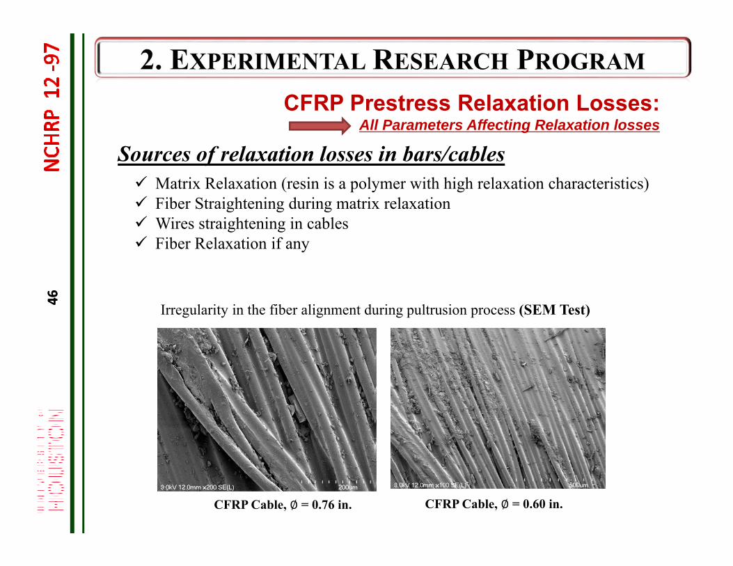
Sources of relaxation losses in bars/cables Matrix Relaxation (resin is a polymer with high relaxation characteristics) Fiber Straightening during matrix relaxation Wires straightening in cables Fiber Relaxation if any
CFRP Cable, ∅ = 0.76 in. CFRP Cable, ∅ = 0.60 in.
Irregularity in the fiber alignment during pultrusion process (SEM Test)
CFRP Prestress Relaxation Losses:All Parameters Affecting Relaxation losses
46
47
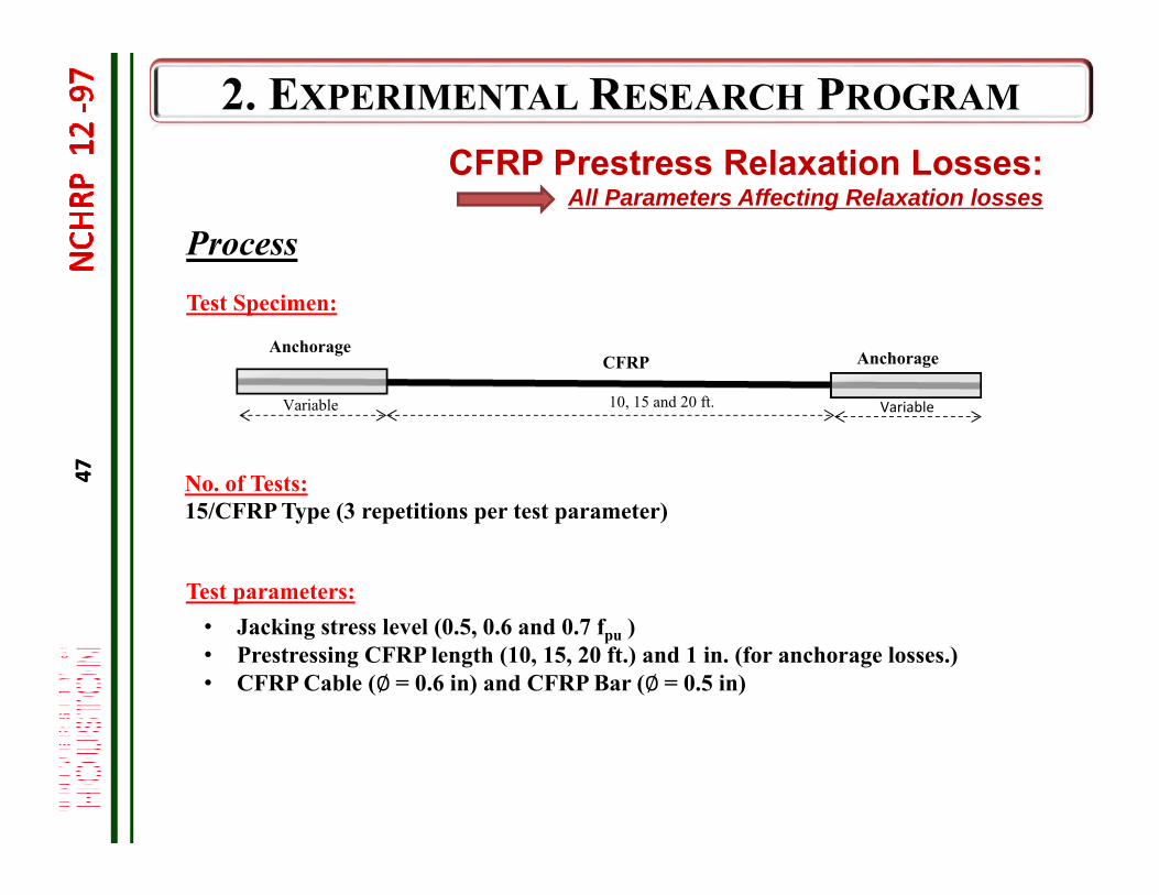
Test parameters:• Jacking stress level (0.5, 0.6 and 0.7 fpu )• Prestressing CFRP length (10, 15, 20 ft.) and 1 in. (for anchorage losses.)• CFRP Cable (∅= 0.6 in) and CFRP Bar (∅= 0.5 in)
Test Specimen:
No. of Tests:15/CFRP Type (3 repetitions per test parameter)
10, 15 and 20 ft. VariableVariable
AnchorageAnchorage
CFRP
Process
CFRP Prestress Relaxation Losses:All Parameters Affecting Relaxation losses
47
48
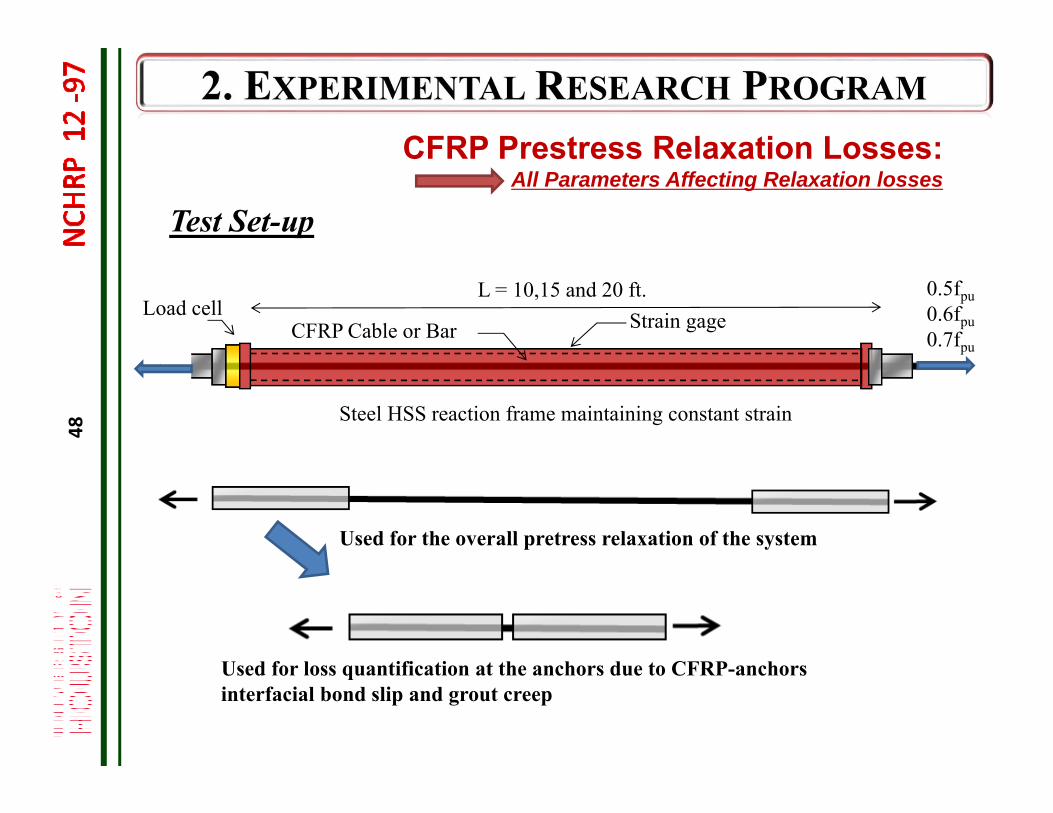
CFRP Cable or Bar
Steel HSS reaction frame maintaining constant strain
Load cellL = 10,15 and 20 ft.
Test Set-up
CFRP Prestress Relaxation Losses:All Parameters Affecting Relaxation losses
Strain gage0.5fpu0.6fpu0.7fpu
Used for the overall pretress relaxation of the system
Used for loss quantification at the anchors due to CFRP-anchors interfacial bond slip and grout creep
49
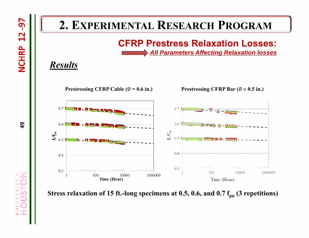
Stress relaxation of 15 ft.-long specimens at 0.5, 0.6, and 0.7 fpu (3 repetitions)
Prestressing CFRP Cable (∅ = 0.6 in.) Prestressing CFRP Bar (∅ 0.5 in.)
Results
CFRP Prestress Relaxation Losses:All Parameters Affecting Relaxation losses
50
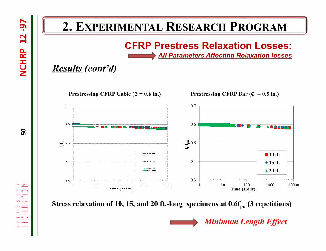
Results (cont’d)
CFRP Prestress Relaxation Losses:All Parameters Affecting Relaxation losses
Prestressing CFRP Cable (∅ = 0.6 in.) Prestressing CFRP Bar (∅ 0.5 in.)
Stress relaxation of 10, 15, and 20 ft.-long specimens at 0.6fpu (3 repetitions)
Minimum Length Effect
51
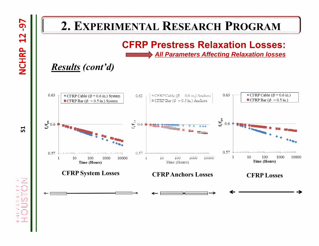
Results (cont’d)
CFRP Prestress Relaxation Losses:All Parameters Affecting Relaxation losses
CFRP System Losses CFRP Anchors Losses CFRP Losses
52
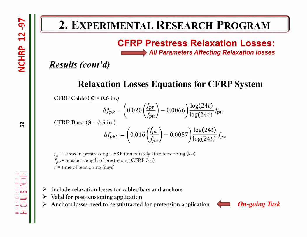
Results (cont’d)
CFRP Prestress Relaxation Losses:All Parameters Affecting Relaxation losses
CFRP Cables( ∅ = 0.6 in.)
Δ 0.020
0.0066log 24log 24 i)
CFRP Bars (∅ = 0.5 in.)
Δ 0.016
0.0057log 24log 24 i)
fpt = stress in prestressing CFRP immediately after tensioning (ksi)= tensile strength of prestressing CFRP (ksi)
ti = time of tensioning (days)
Relaxation Losses Equations for CFRP System
Include relaxation losses for cables/bars and anchors Valid for post-tensioning application Anchors losses need to be subtracted for pretension application On-going Task
53
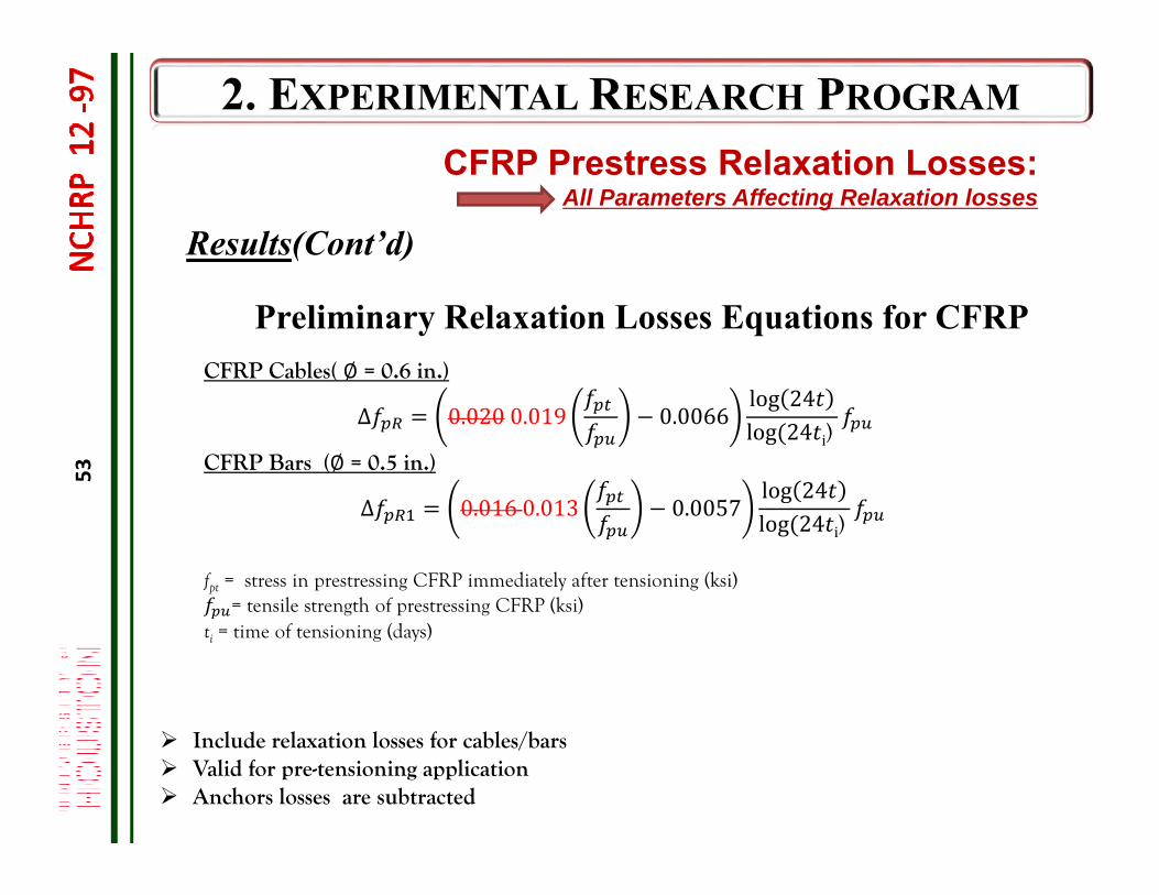
Results(Cont’d)
CFRP Prestress Relaxation Losses:All Parameters Affecting Relaxation losses
CFRP Cables( ∅ = 0.6 in.)
Δ 0.0200.019
0.0066log 24log 24 i)
CFRP Bars (∅ = 0.5 in.)
Δ 0.0160.013
0.0057log 24log 24 i)
fpt = stress in prestressing CFRP immediately after tensioning (ksi)= tensile strength of prestressing CFRP (ksi)
ti = time of tensioning (days)
Preliminary Relaxation Losses Equations for CFRP
Include relaxation losses for cables/bars Valid for pre-tensioning application Anchors losses are subtracted
54
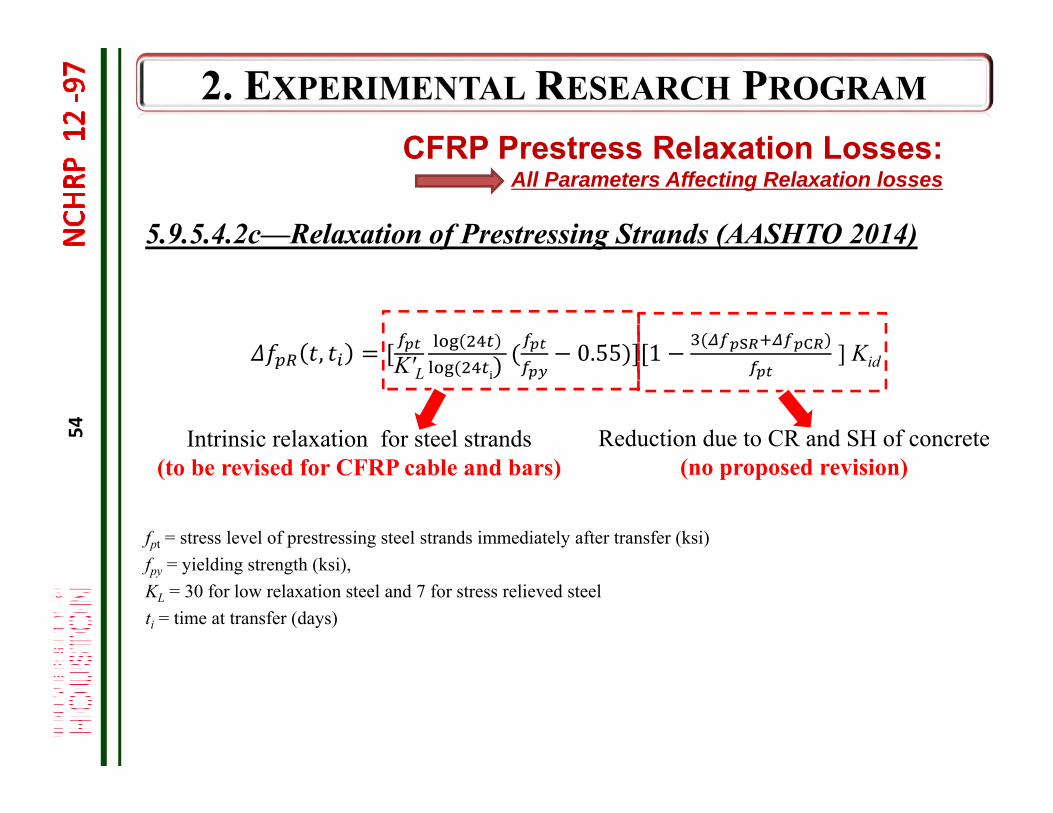
, K′L 0.55 1 ] Kid
fpt = stress level of prestressing steel strands immediately after transfer (ksi)fpy = yielding strength (ksi), KL = 30 for low relaxation steel and 7 for stress relieved steelti = time at transfer (days)
5.9.5.4.2c—Relaxation of Prestressing Strands (AASHTO 2014)
Intrinsic relaxation for steel strands(to be revised for CFRP cable and bars)
Reduction due to CR and SH of concrete(no proposed revision)
CFRP Prestress Relaxation Losses:All Parameters Affecting Relaxation losses
55
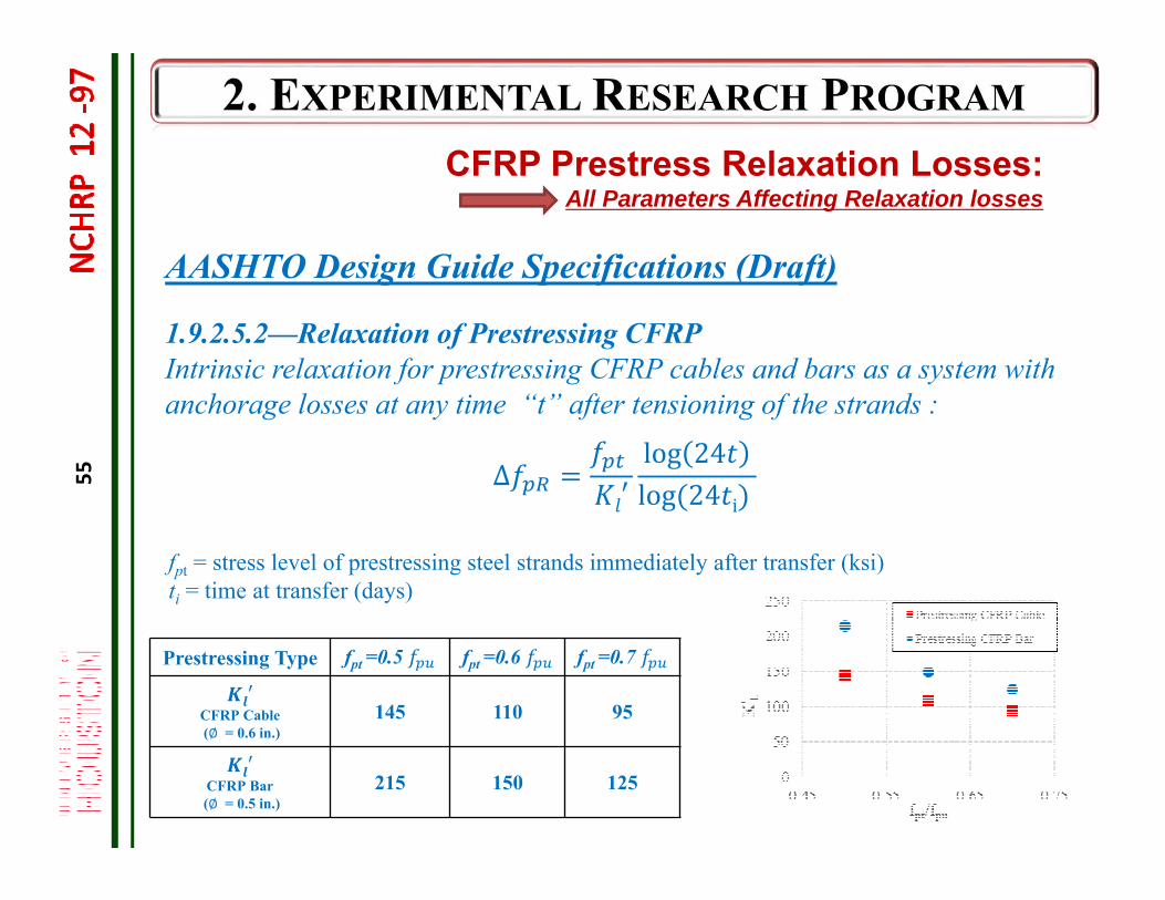
Prestressing Type fpt =0.5 fpt =0.6 fpt =0.7
′CFRP Cable(∅ = 0.6 in.)
145 110 95
′CFRP Bar(∅ = 0.5 in.)
215 150 125
CFRP Prestress Relaxation Losses:All Parameters Affecting Relaxation losses
AASHTO Design Guide Specifications (Draft)
1.9.2.5.2—Relaxation of Prestressing CFRPIntrinsic relaxation for prestressing CFRP cables and bars as a system with anchorage losses at any time “t” after tensioning of the strands :
Δ′log 24log 24 i
fpt = stress level of prestressing steel strands immediately after transfer (ksi) ti = time at transfer (days)
56
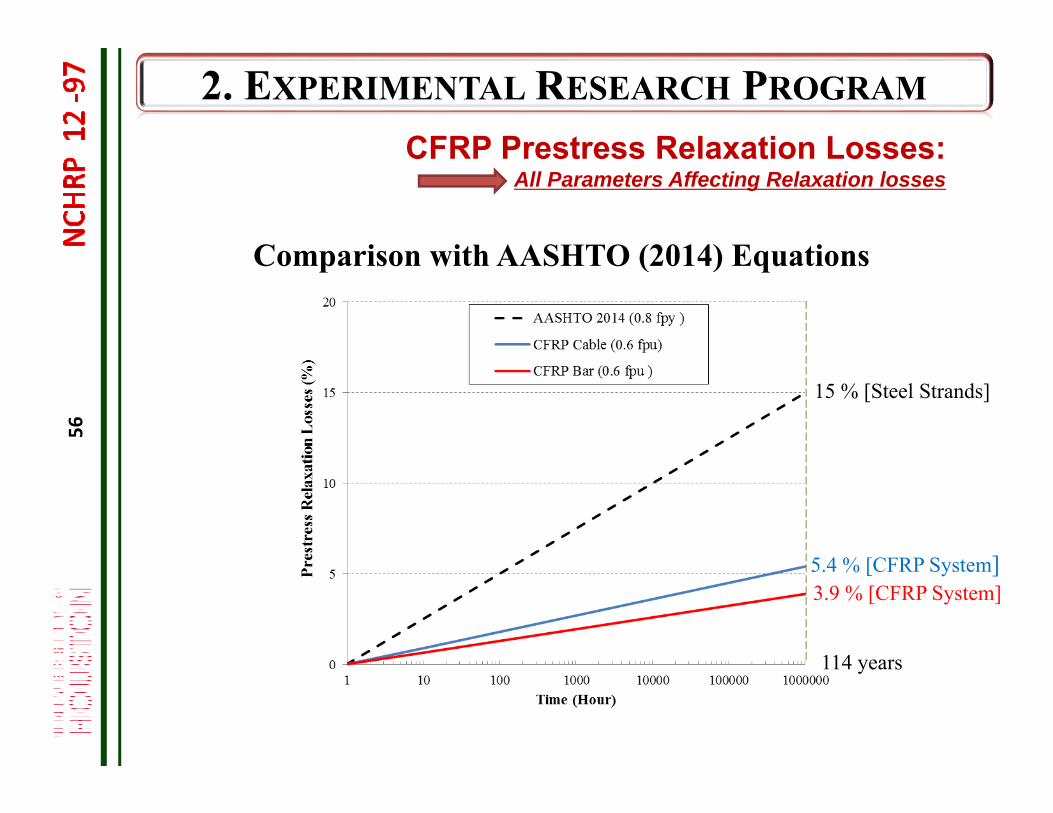
114 years
5.4 % [CFRP System]3.9 % [CFRP System]
CFRP Prestress Relaxation Losses:All Parameters Affecting Relaxation losses
Comparison with AASHTO (2014) Equations
15 % [Steel Strands]
57
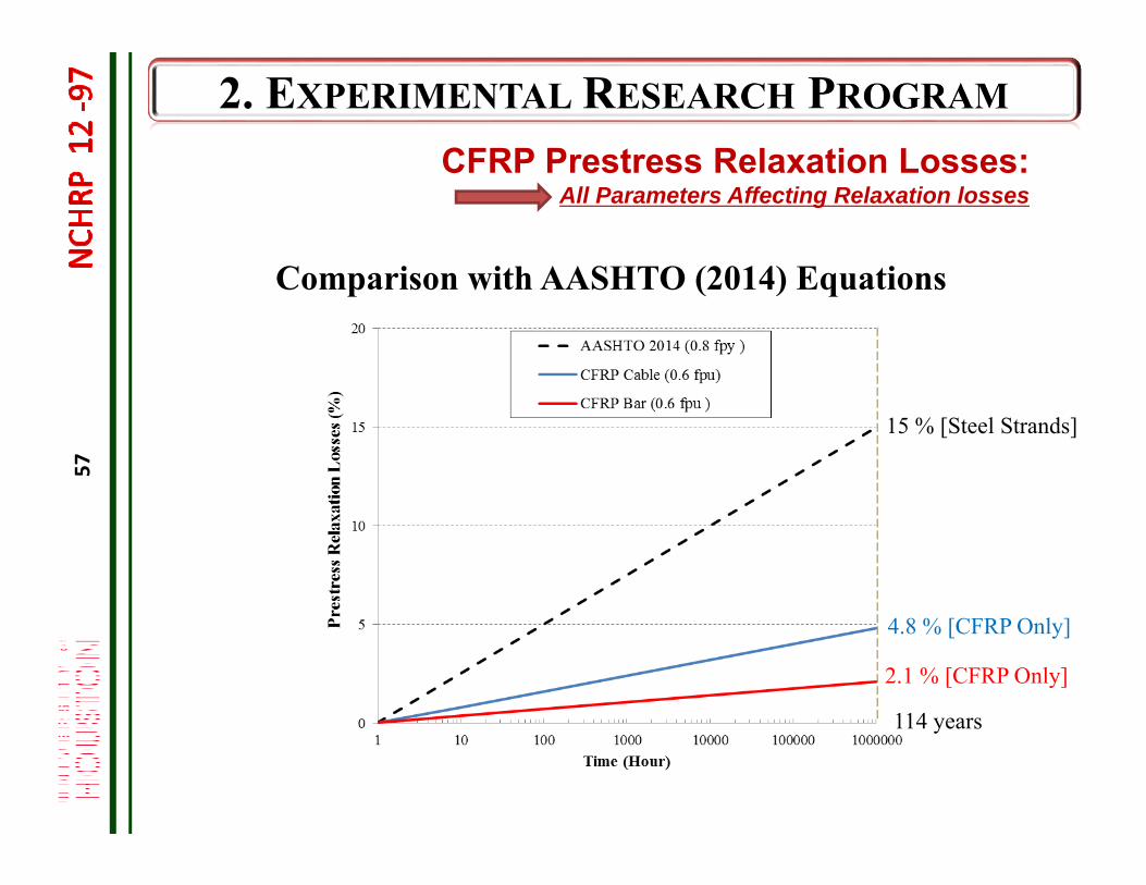
114 years
4.8 % [CFRP Only]
2.1 % [CFRP Only]
CFRP Prestress Relaxation Losses:All Parameters Affecting Relaxation losses
15 % [Steel Strands]
Comparison with AASHTO (2014) Equations
58
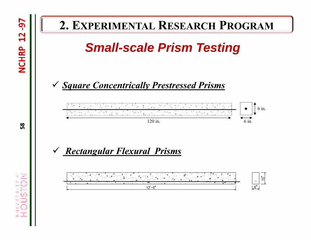
Small-scale Prism Testing
Square Concentrically Prestressed Prisms
Rectangular Flexural Prisms
58
6 in.
6 in.
120 in.
59
Small-scale Prism Testing
Evaluation of Creep and Shrinkage of Concrete Evaluation of Thermal Fluctuation Losses Evaluation of Transfer Length
Square Concentrically Prestressed Prisms
Test Procedures Test Results Applicable Design Guide Specifications/Material Specifications
59
60
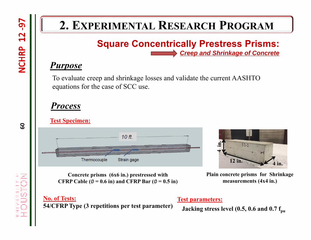
To evaluate creep and shrinkage losses and validate the current AASHTO equations for the case of SCC use.
Purpose
No. of Tests:54/CFRP Type (3 repetitions per test parameter)
Test Specimen:
Concrete prisms (6x6 in.) prestressed with CFRP Cable (∅= 0.6 in) and CFRP Bar (∅= 0.5 in)
Process
Square Concentrically Prestress Prisms:Creep and Shrinkage of Concrete
Plain concrete prisms for Shrinkage measurements (4x4 in.)
4 in.12 in.
4 in
.
Test parameters:Jacking stress level (0.5, 0.6 and 0.7 fpu
61
S
S
. u
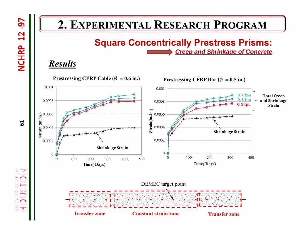
Results
pStrain
Transfer zoneTransfer zone Constant strain zone
Prestressing CFRP Bar (∅ 0.5 in.)Prestressing CFRP Cable (∅ 0.6 in.)
Square Concentrically Prestress Prisms:Creep and Shrinkage of Concrete
DEMEC target point
. u. u
62
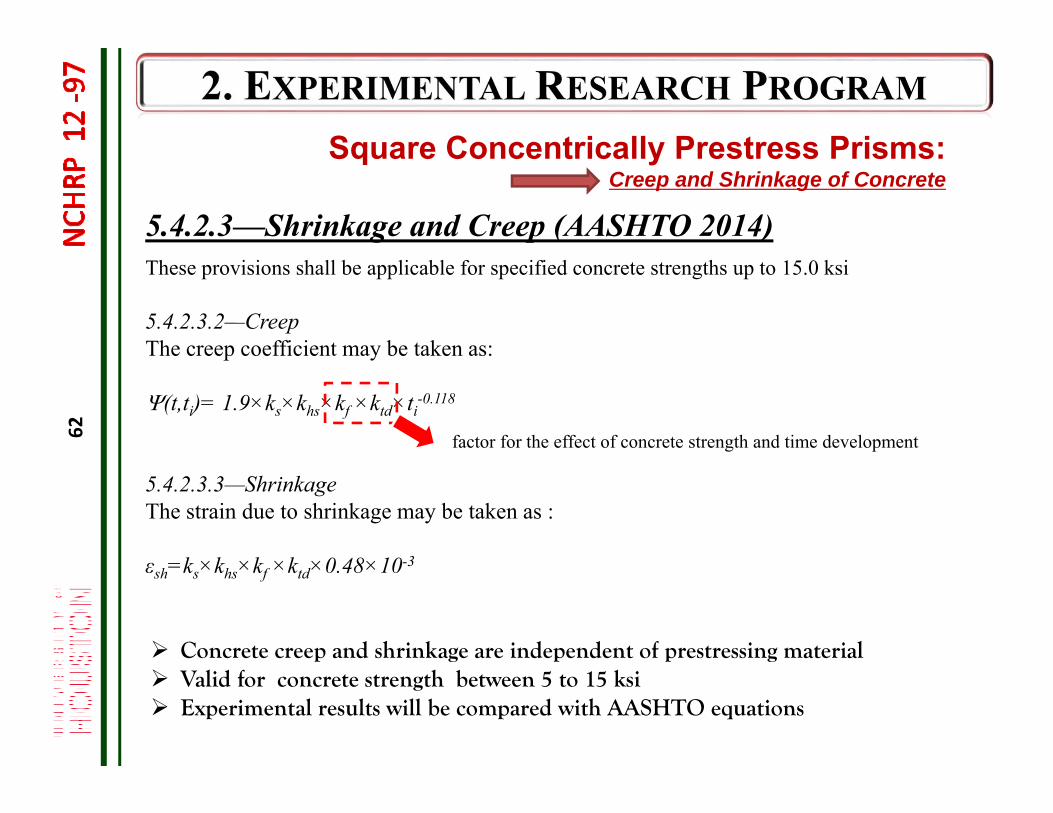
5.4.2.3—Shrinkage and Creep (AASHTO 2014)These provisions shall be applicable for specified concrete strengths up to 15.0 ksi
5.4.2.3.2—CreepThe creep coefficient may be taken as:
(t,ti)= 1.9×ks×khs×kf ×ktd×ti-0.118
5.4.2.3.3—ShrinkageThe strain due to shrinkage may be taken as :
εsh=ks×khs×kf ×ktd×0.48×10⁻³
factor for the effect of concrete strength and time development
Square Concentrically Prestress Prisms:Creep and Shrinkage of Concrete
Concrete creep and shrinkage are independent of prestressing material Valid for concrete strength between 5 to 15 ksi Experimental results will be compared with AASHTO equations
63
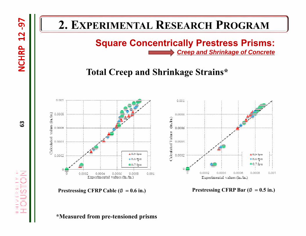
Prestressing CFRP Cable (∅ 0.6 in.) Prestressing CFRP Bar (∅ 0.5 in.)
Square Concentrically Prestress Prisms:Creep and Shrinkage of Concrete
Total Creep and Shrinkage Strains*
*Measured from pre-tensioned prisms
64
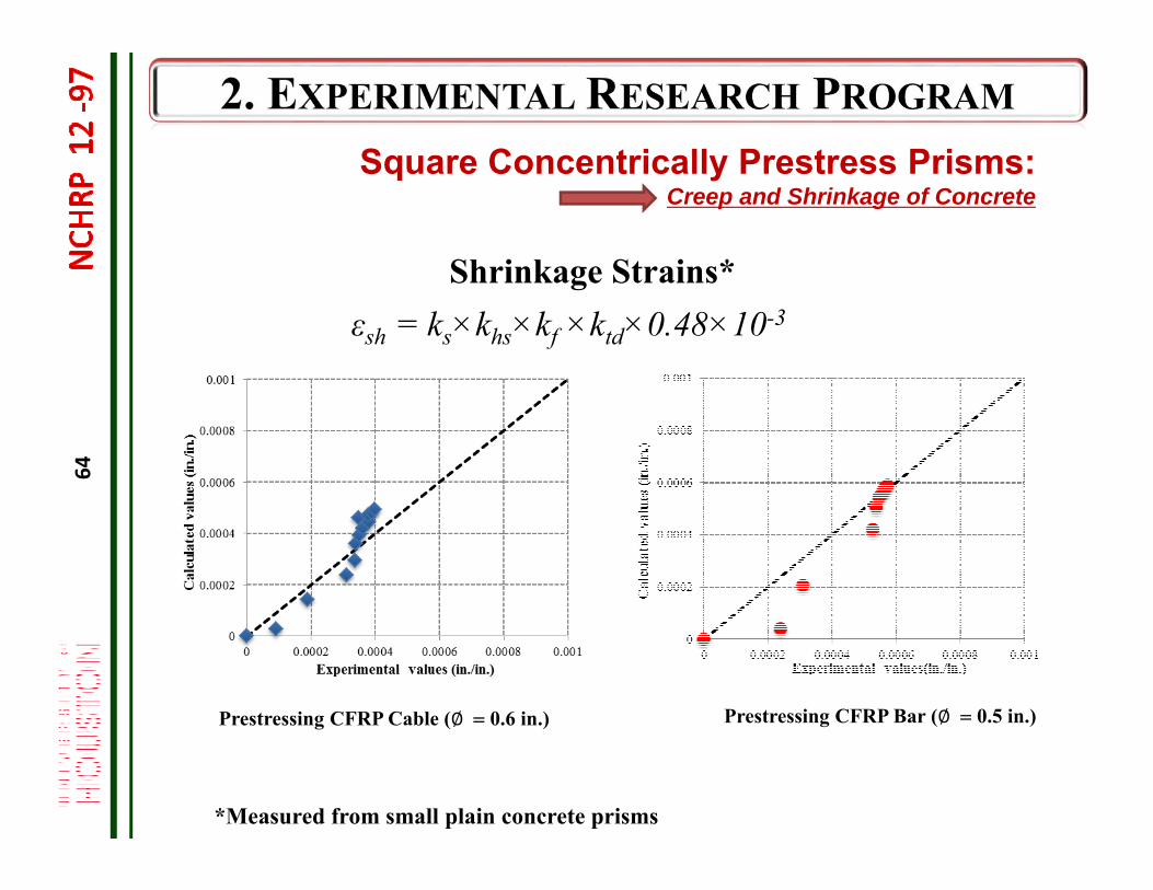
Prestressing CFRP Cable (∅ 0.6 in.) Prestressing CFRP Bar (∅ 0.5 in.)
Square Concentrically Prestress Prisms:Creep and Shrinkage of Concrete
Shrinkage Strains*
*Measured from small plain concrete prisms
εsh = ks×khs×kf ×ktd×0.48×10⁻³
65
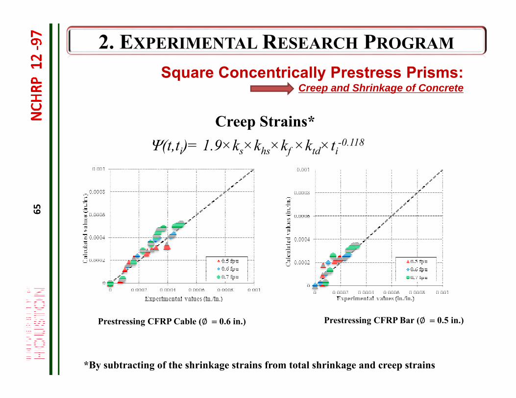
Prestressing CFRP Cable (∅ 0.6 in.) Prestressing CFRP Bar (∅ 0.5 in.)
Square Concentrically Prestress Prisms:Creep and Shrinkage of Concrete
Creep Strains*
*By subtracting of the shrinkage strains from total shrinkage and creep strains
(t,ti)= 1.9×ks×khs×kf ×ktd×ti-0.118
66
AASHTO Design Guide Specifications (Draft)
1.9.2.5—Refined Estimate of Time-Dependent Losses:In accordance with the provisions of Article 5.9.5.4 of the AASHTO LRFD Bridge Design Specifications (2014)
No changes for creep and shrinkage losses
Square Concentrically Prestress Prisms:Creep and Shrinkage of Concrete
67
lfrpcTl ,
Purpose
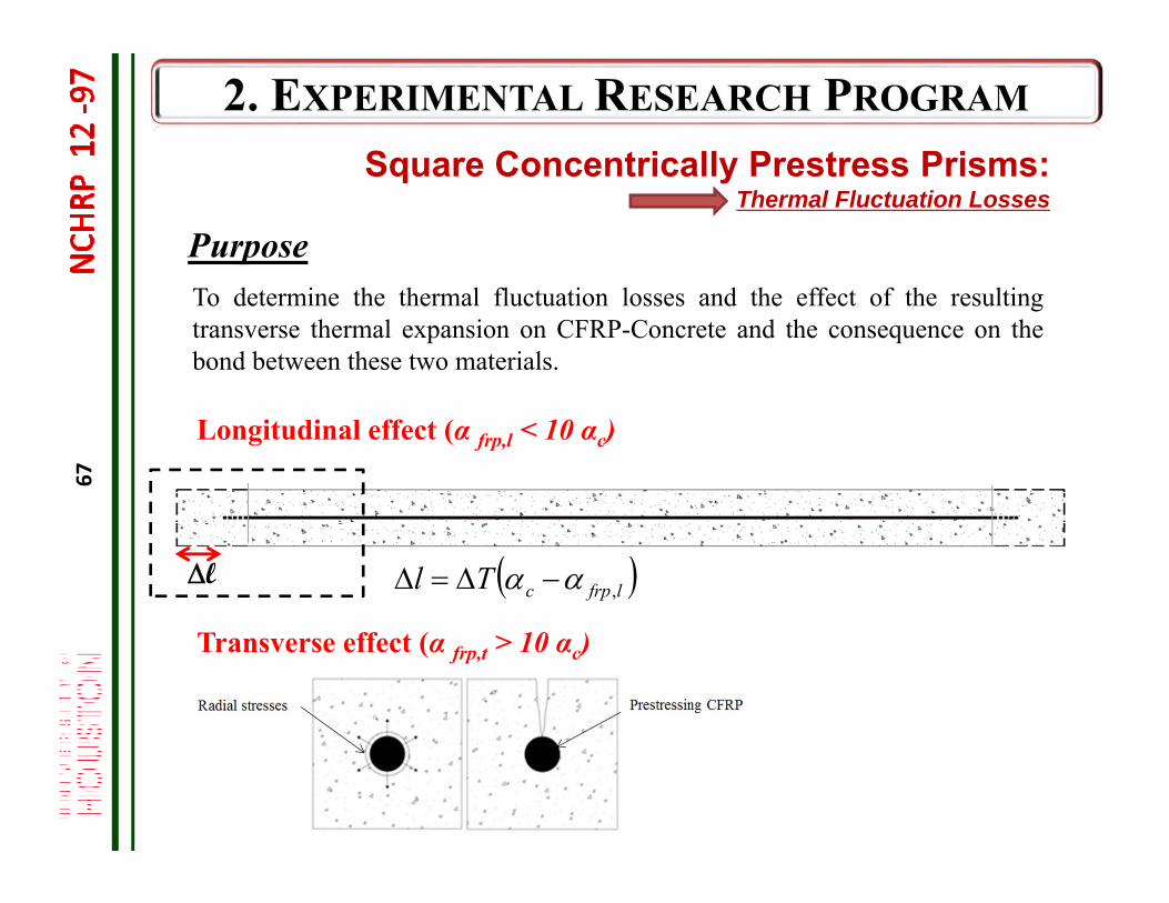
Square Concentrically Prestress Prisms:Thermal Fluctuation Losses
Longitudinal effect (α frp,l < 10 αc)
Transverse effect (α frp,t > 10 αc)
l
To determine the thermal fluctuation losses and the effect of the resultingtransverse thermal expansion on CFRP-Concrete and the consequence on thebond between these two materials.
68
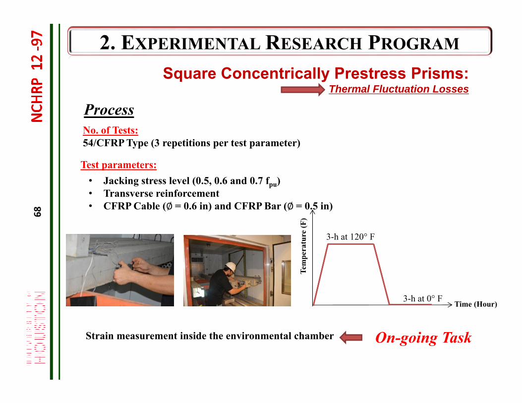
Strain measurement inside the environmental chamber
Test parameters:• Jacking stress level (0.5, 0.6 and 0.7 fpu)• Transverse reinforcement• CFRP Cable (∅= 0.6 in) and CFRP Bar (∅= 0.5 in)
No. of Tests:54/CFRP Type (3 repetitions per test parameter)
Process
3-h at 0° F Time (Hour)Te
mpe
ratu
re (F
)
Square Concentrically Prestress Prisms:Thermal Fluctuation Losses
On-going Task
3-h at 120° F
69
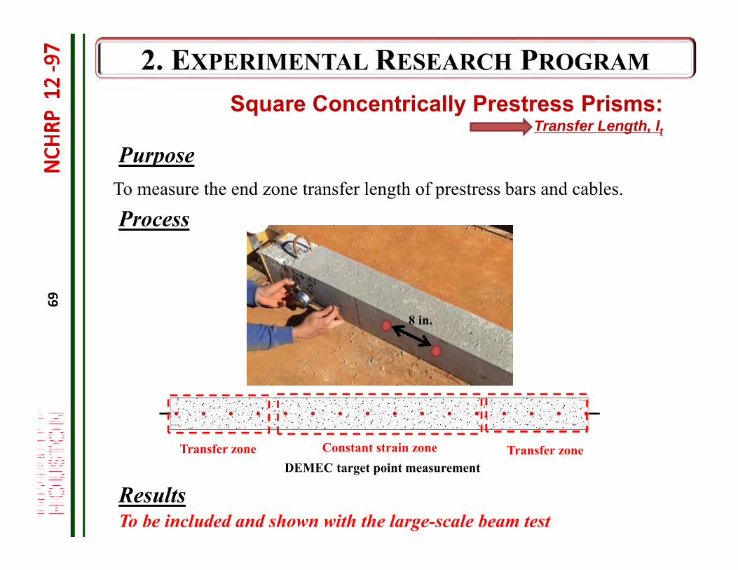
To measure the end zone transfer length of prestress bars and cables.
Purpose
Square Concentrically Prestress Prisms:Transfer Length, lt
Process
ResultsTo be included and shown with the large-scale beam test
Transfer zoneConstant strain zoneTransfer zoneDEMEC target point measurement
8 in.
70
Small-scale Prism Testing
Evaluation of Long-term Deflections Evaluation of Transfer Length
Rectangular Flexural Prisms
Test Procedures Test Results
70
71
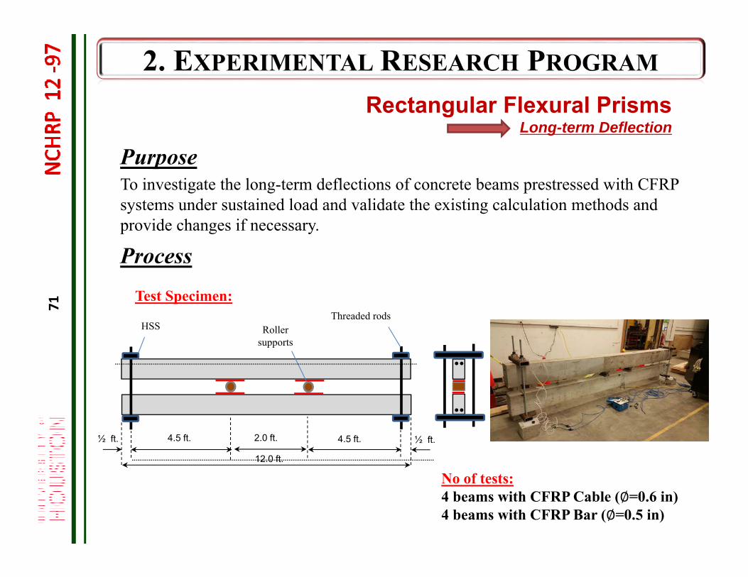
Rectangular Flexural Prisms Long-term Deflection
PurposeTo investigate the long-term deflections of concrete beams prestressed with CFRP systems under sustained load and validate the existing calculation methods and provide changes if necessary.
Process
12.0 ft.
2.0 ft. 4.5 ft.4.5 ft. ½ ft.½ ft.
Threaded rodsHSS Roller
supports
Test Specimen:
No of tests:4 beams with CFRP Cable (∅=0.6 in)4 beams with CFRP Bar (∅=0.5 in)
72
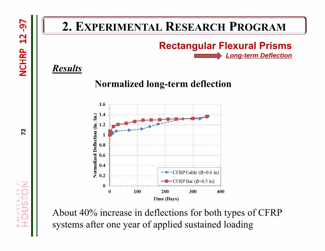
Rectangular Flexural Prisms Long-term Deflection
Results
About 40% increase in deflections for both types of CFRP systems after one year of applied sustained loading
Normalized long-term deflection
73
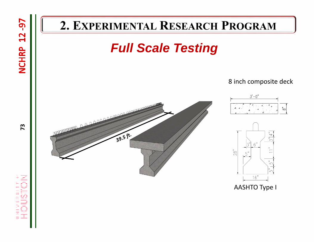
AASHTO Type I
8 inch composite deck
Full Scale Testing
74
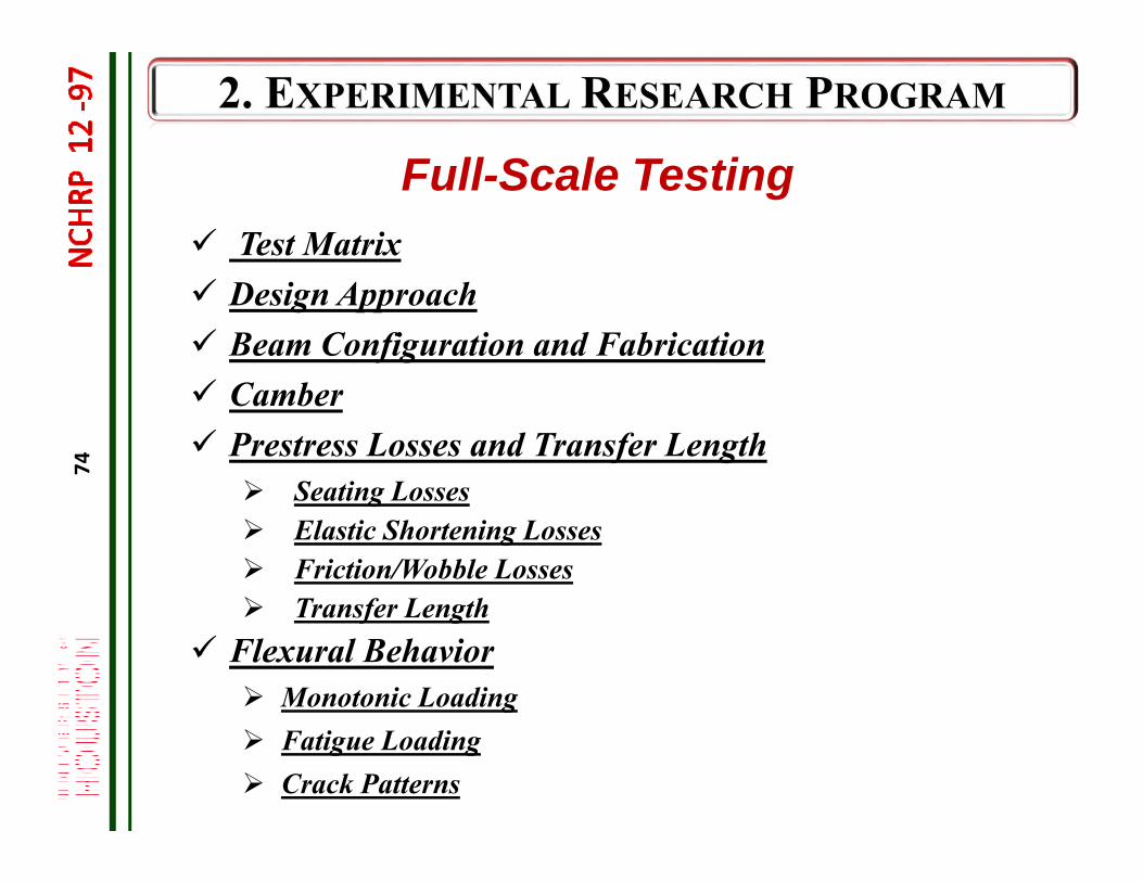
Full-Scale Testing Test Matrix Design Approach Beam Configuration and Fabrication Camber Prestress Losses and Transfer Length
Seating Losses Elastic Shortening Losses Friction/Wobble Losses Transfer Length
Flexural Behavior Monotonic Loading Fatigue Loading Crack Patterns
75
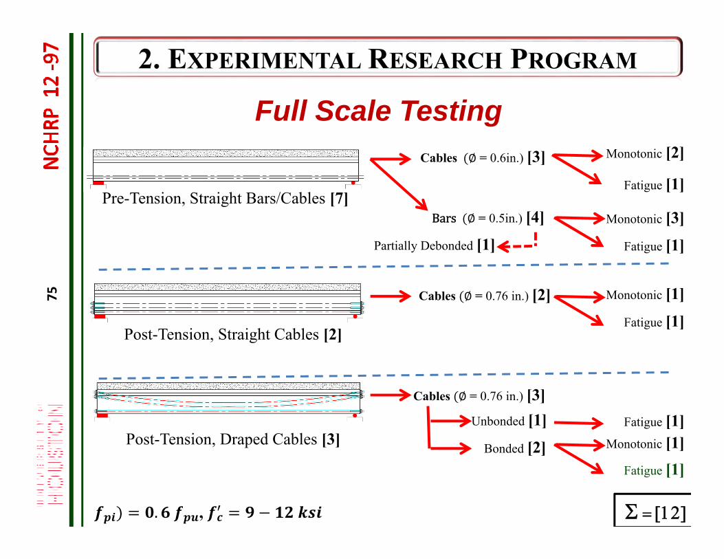
Full Scale Testing
Pre-Tension, Straight Bars/Cables [7]
Unbonded [1]
Bonded [2]
Cables ∅ = 0.76 in.) [3]
Cables ∅ = 0.6in.) [3]
Fatigue [1]
Cables ∅ = 0.76 in.) [2]
. ,
Post-Tension, Straight Cables [2]
Post-Tension, Draped Cables [3]
Bars ∅ = 0.5in.) [4]
Monotonic [2]
Partially Debonded [1]Monotonic [3]
Fatigue [1]
Monotonic [1]
Fatigue [1]
Fatigue [1]
Fatigue [1]Monotonic [1]
76
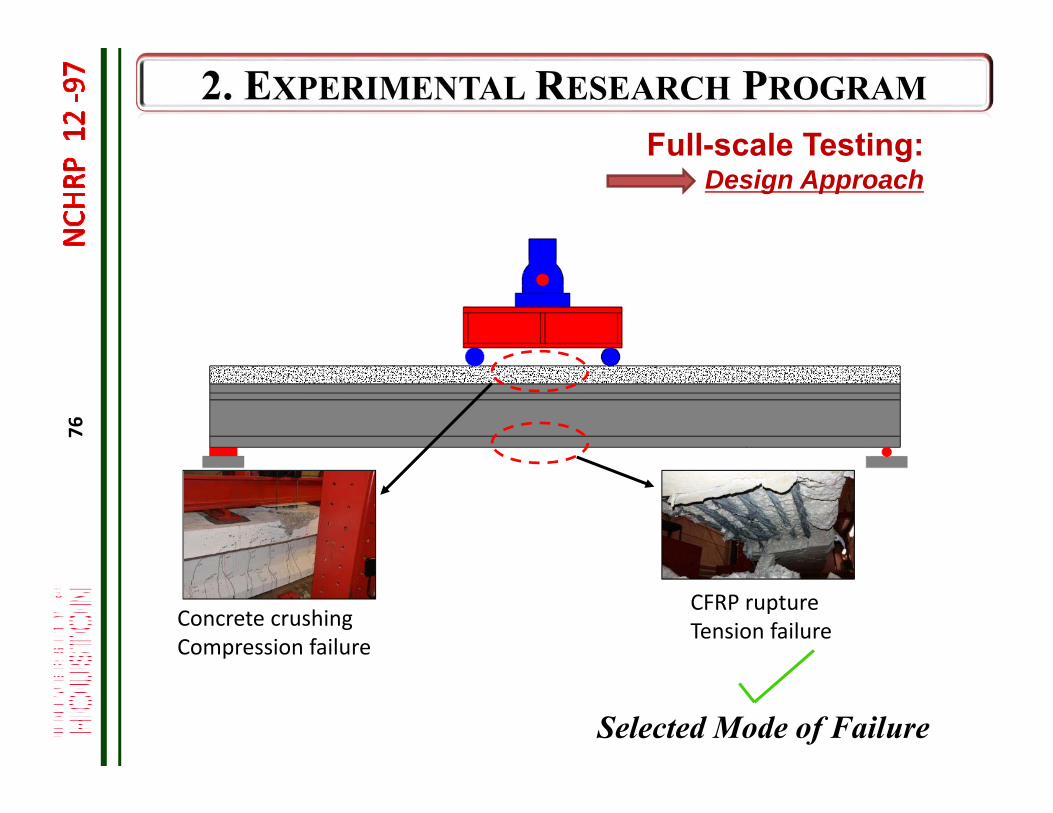
Concrete crushingCompression failure
CFRP ruptureTension failure
Selected Mode of Failure
Full-scale Testing:Design Approach
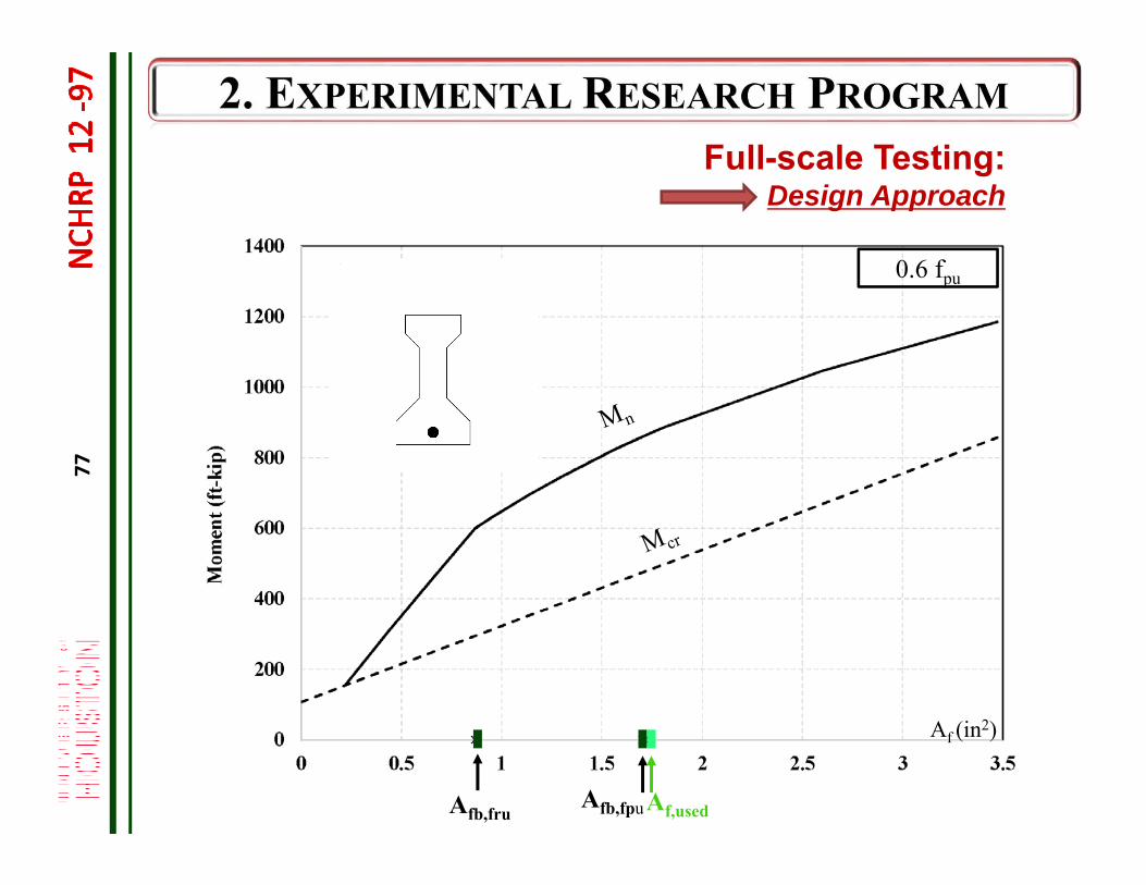
77
Full-scale Testing:Design Approach
0.6 fpu
Af (in2)
Af,usedAfb,fruAfb,fpu
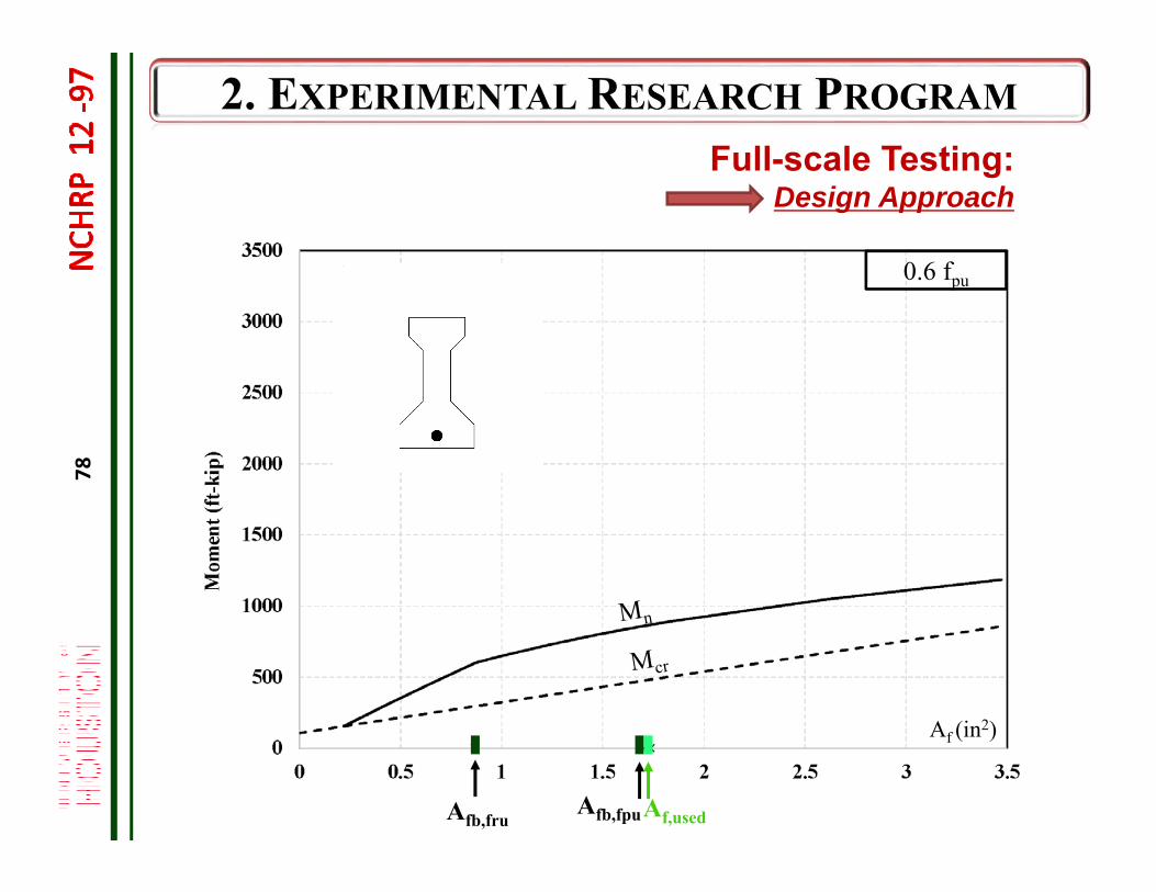
78
Full-scale Testing:Design Approach
0.6 fpu
Af (in2)
Afb,fru Af,usedAfb,fpu
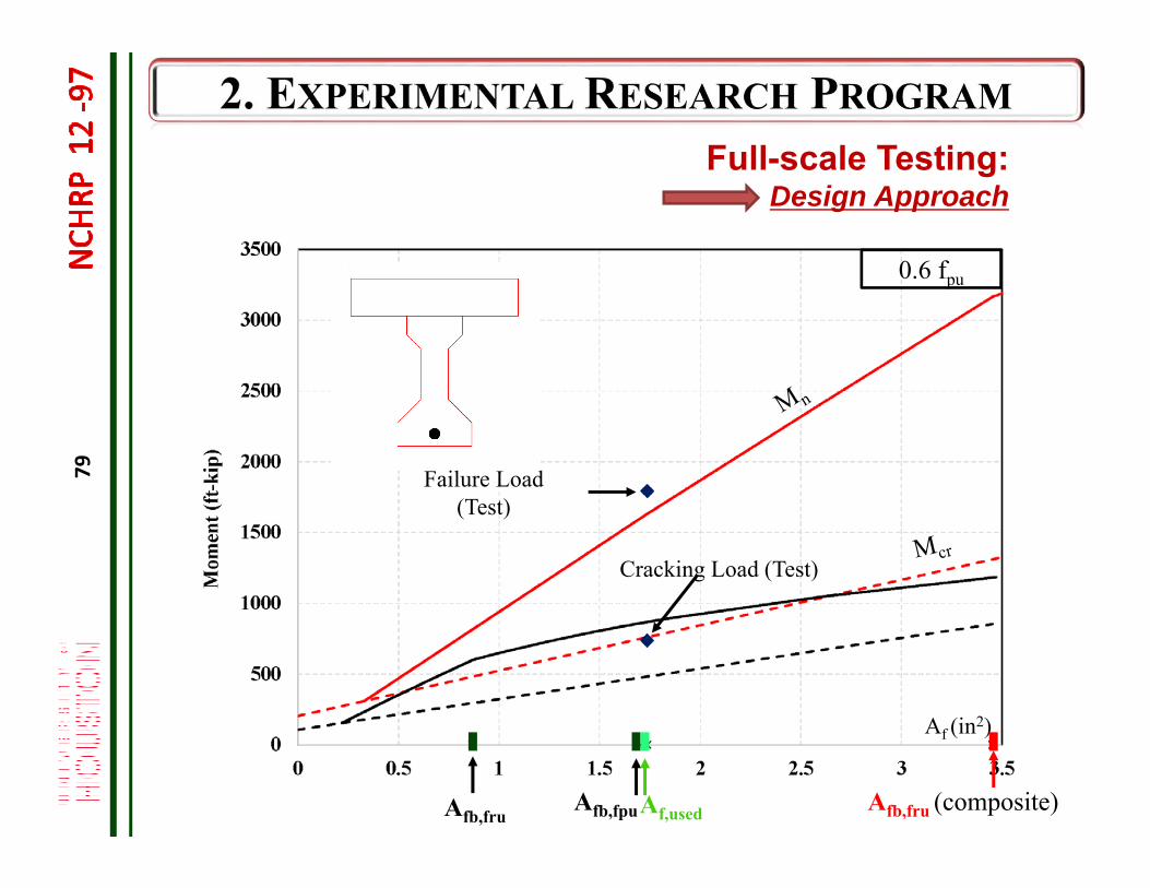
79
0.6 fpu
Afb,fru (composite)
Af (in2)
Failure Load (Test)
Cracking Load (Test)
Full-scale Testing:Design Approach
Afb,fru Af,usedAfb,fpu
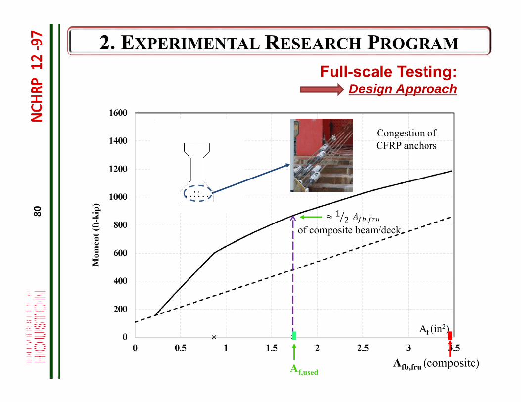
80
Af (in2)
12 ,
of composite beam/deck
Congestion of CFRP anchors
Full-scale Testing:Design Approach
Afb,fru (composite)Af,used
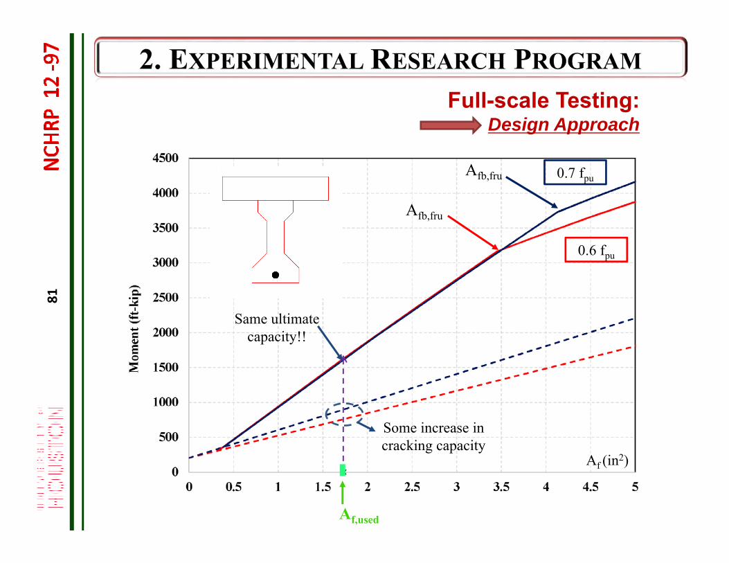
81
Afb,fru
Afb,fru
0.6 fpu
0.7 fpu
Same ultimate capacity!!
Some increase in cracking capacity
Full-scale Testing:Design Approach
Af (in2)
Af,used
82
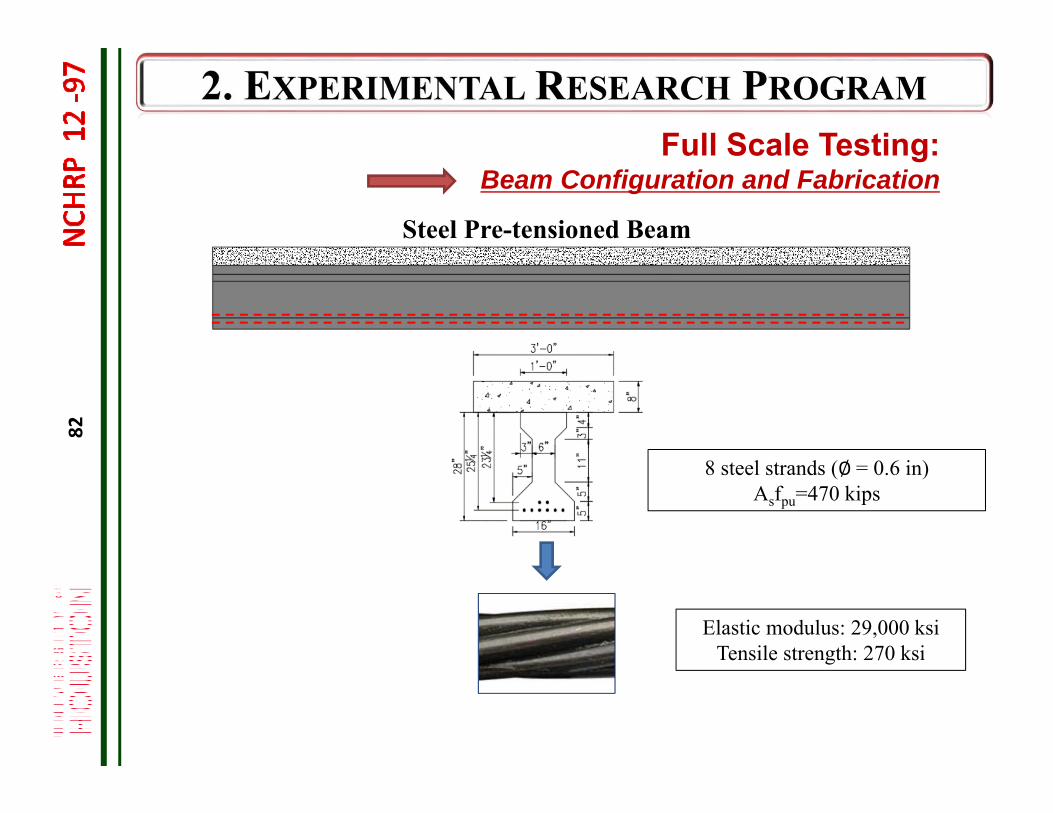
Full Scale Testing: Beam Configuration and Fabrication
Steel Pre-tensioned Beam
Elastic modulus: 29,000 ksiTensile strength: 270 ksi
8 steel strands (∅= 0.6 in)Asfpu=470 kips
83
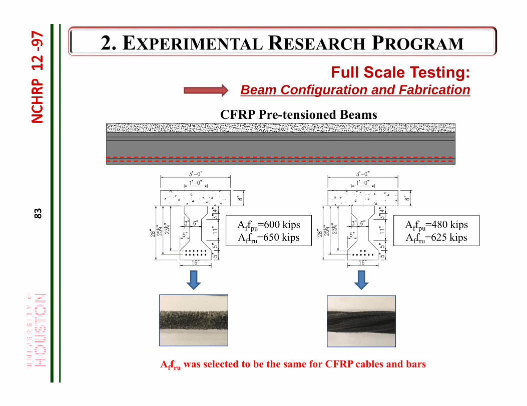
Affru was selected to be the same for CFRP cables and bars
CFRP Pre-tensioned Beams
Affpu=600 kipsAffru=650 kips
Affpu=480 kipsAffru=625 kips
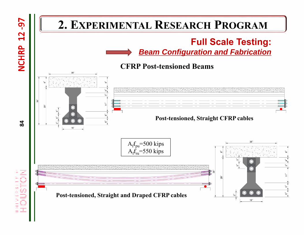
Full Scale Testing: Beam Configuration and Fabrication
84
Post-tensioned, Straight CFRP cables
CFRP Post-tensioned Beams
Affpu=500 kipsAffru=550 kips
Post-tensioned, Straight and Draped CFRP cables
Full Scale Testing: Beam Configuration and Fabrication
85
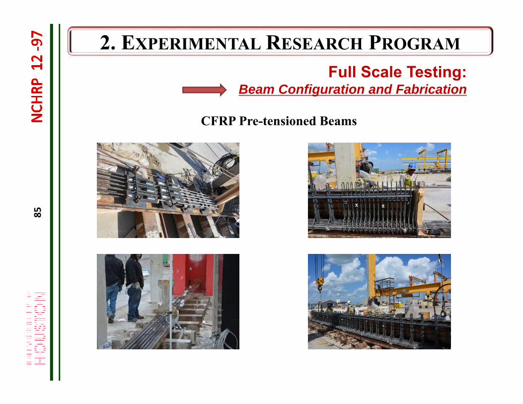
CFRP Pre-tensioned Beams
Full Scale Testing: Beam Configuration and Fabrication
86
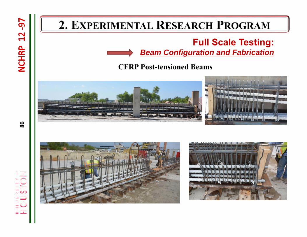
CFRP Post-tensioned Beams
Full Scale Testing: Beam Configuration and Fabrication
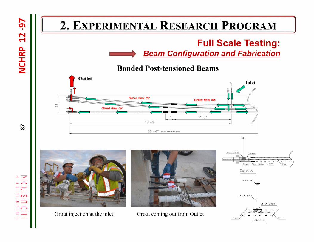
87
Bonded Post-tensioned Beams
Grout injection at the inlet Grout coming out from Outlet
Full Scale Testing: Beam Configuration and Fabrication
88
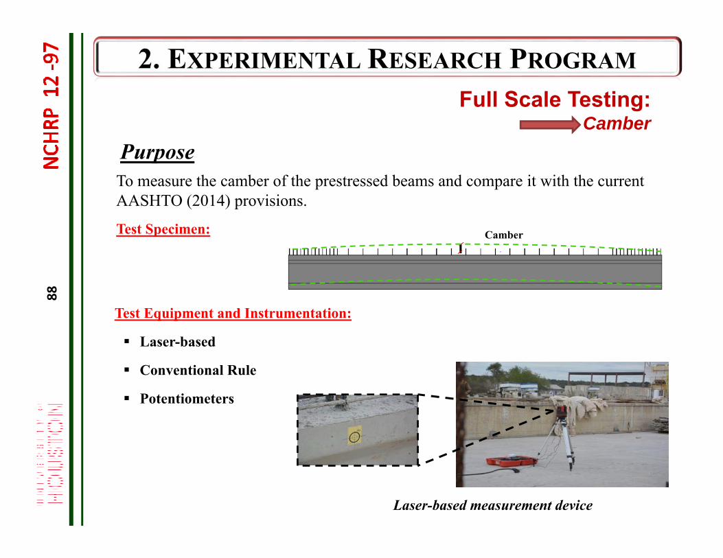
Test Equipment and Instrumentation:
Laser-based
Conventional Rule
Potentiometers
Laser-based measurement device
CamberTest Specimen:
Full Scale Testing: Camber
PurposeTo measure the camber of the prestressed beams and compare it with the current AASHTO (2014) provisions.
89
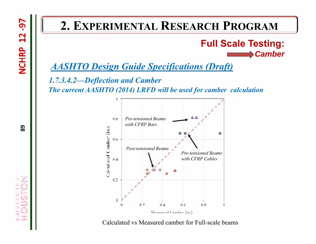
Calculated vs Measured camber for Full-scale beams
AASHTO Design Guide Specifications (Draft) 1.7.3.4.2—Deflection and Camber
Pre-tensioned Beams with CFRP Cables
Pre-tensioned Beams with CFRP Bars
Post-tensioned Beams
The current AASHTO (2014) LRFD will be used for camber calculation
Full Scale Testing: Camber

90
Full-Scale TestingPrestress Losses and Transfer Length
Seating Losses Elastic Shortening Losses Wobble and Friction Losses Prestress Transfer Length
91
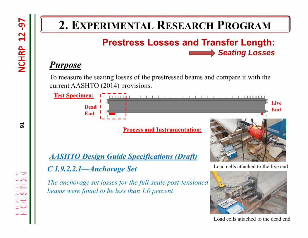
Load cells attached to the dead end
Dead End
Live End
Load cells attached to the live end
Test Specimen:
Process and Instrumentation:
Prestress Losses and Transfer Length: Seating Losses
PurposeTo measure the seating losses of the prestressed beams and compare it with the current AASHTO (2014) provisions.
The anchorage set losses for the full-scale post-tensioned beams were found to be less than 1.0 percent
AASHTO Design Guide Specifications (Draft) C 1.9.2.2.1—Anchorage Set
92
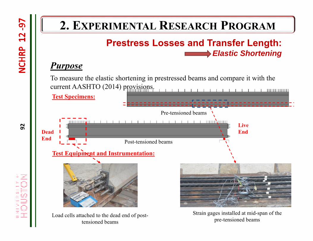
Test Specimens:
Strain gages installed at mid-span of the pre-tensioned beams
Dead End
Live End
Load cells attached to the dead end of post-tensioned beams
Pre-tensioned beams
Post-tensioned beams
Test Equipment and Instrumentation:
Prestress Losses and Transfer Length:Elastic Shortening
To measure the elastic shortening in prestressed beams and compare it with the current AASHTO (2014) provisions.
Purpose
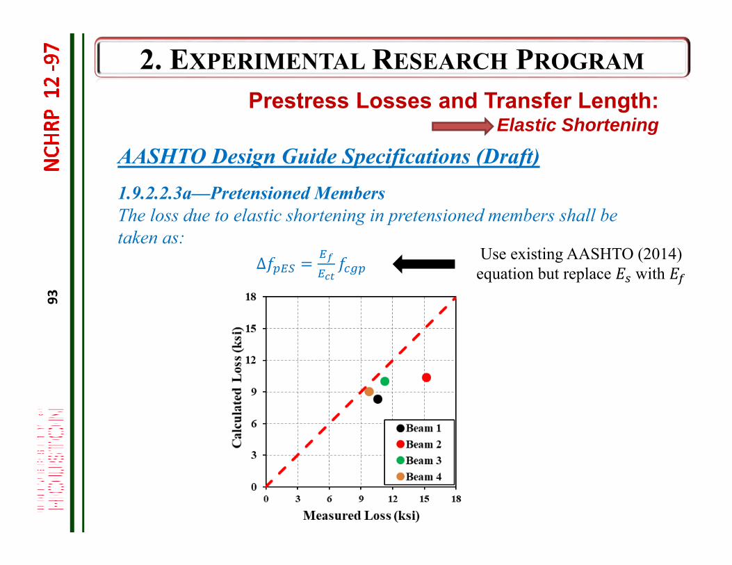
93
AASHTO Design Guide Specifications (Draft) 1.9.2.2.3a—Pretensioned MembersThe loss due to elastic shortening in pretensioned members shall be taken as:
Δ Use existing AASHTO (2014) equation but replace with
Prestress Losses and Transfer Length:Elastic Shortening
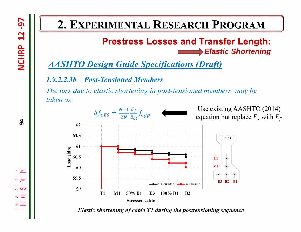
94
1.9.2.2.3b—Post-Tensioned MembersThe loss due to elastic shortening in post-tensioned members may be taken as:
∆
Elastic shortening of cable T1 during the posttensioning sequence
T1
M1
B1 B2 B3
AASHTO Design Guide Specifications (Draft)
Prestress Losses and Transfer Length:Elastic Shortening
Use existing AASHTO (2014) equation but replace with
95
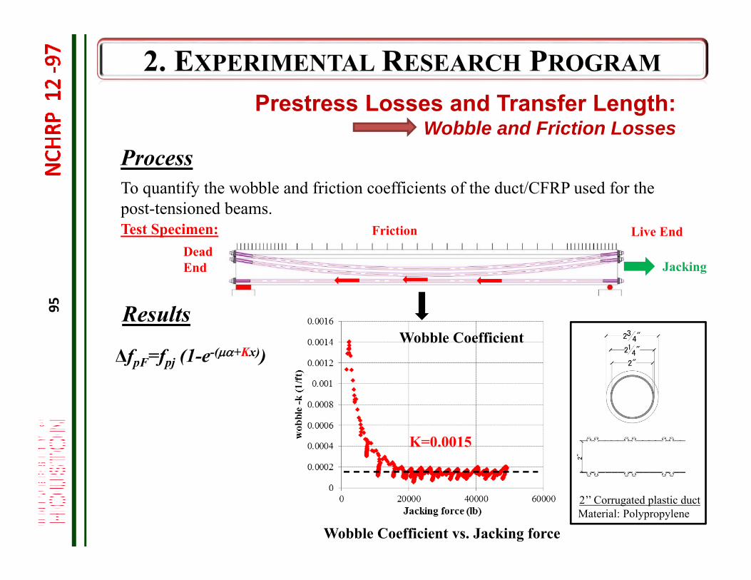
Dead End
Live End Friction
Jacking
Test Specimen:
Process
Prestress Losses and Transfer Length: Wobble and Friction Losses
Wobble Coefficient vs. Jacking force
K=0.0015
ΔfpF=fpj (1-e-(+Kx))
ResultsWobble Coefficient
To quantify the wobble and friction coefficients of the duct/CFRP used for the post-tensioned beams.
2’’ Corrugated plastic ductMaterial: Polypropylene
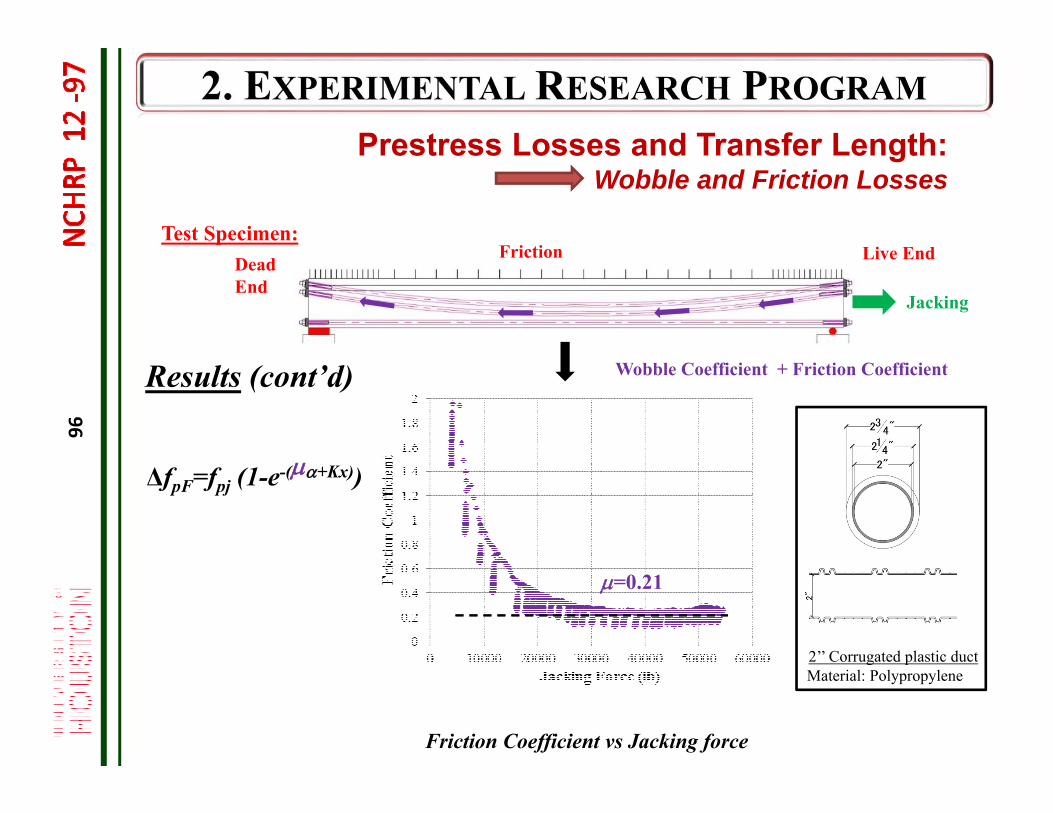
96
Test Specimen:Dead End
Live End Friction
Jacking
Friction Coefficient vs Jacking force
=0.21
ΔfpF=fpj (1-e-(+Kx))
Wobble Coefficient + Friction Coefficient Results (cont’d)
2’’ Corrugated plastic ductMaterial: Polypropylene
Prestress Losses and Transfer Length: Wobble and Friction Losses
97
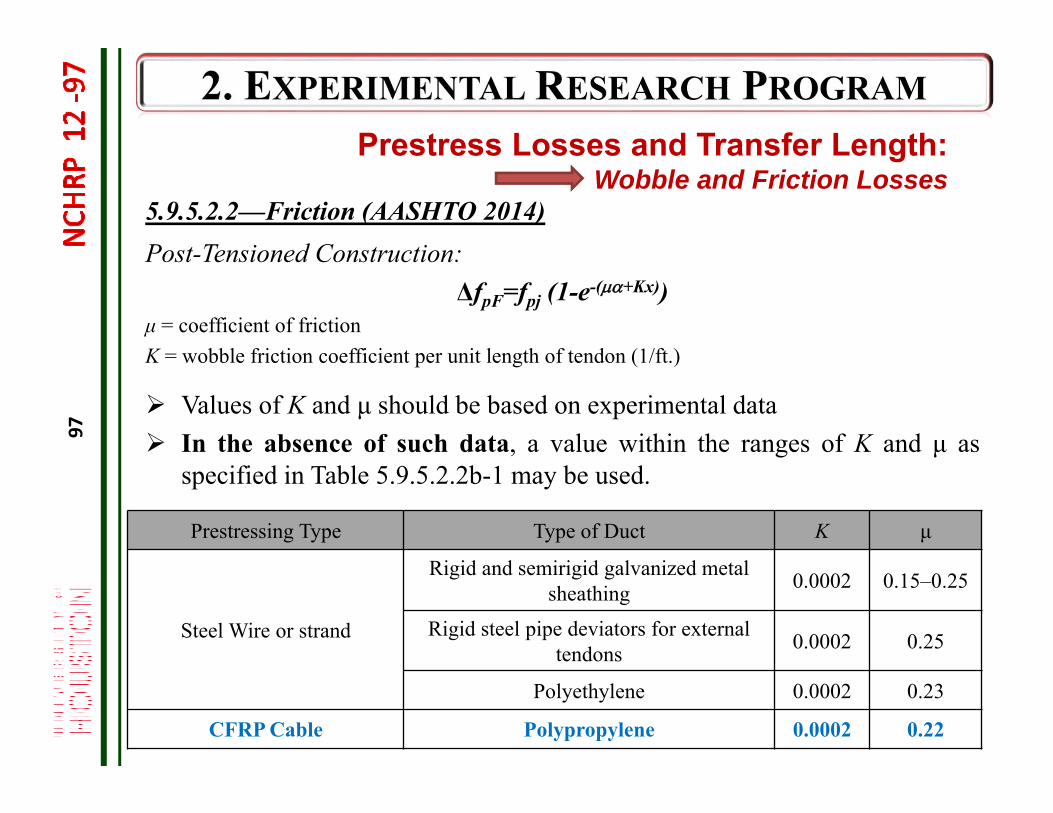
Post-Tensioned Construction:ΔfpF=fpj (1-e-(+Kx))
μ = coefficient of frictionK = wobble friction coefficient per unit length of tendon (1/ft.)
5.9.5.2.2—Friction (AASHTO 2014)
Prestress Losses and Transfer Length: Wobble and Friction Losses
Values of K and μ should be based on experimental data In the absence of such data, a value within the ranges of K and μ as
specified in Table 5.9.5.2.2b-1 may be used.
Prestressing Type Type of Duct K μ
Steel Wire or strand
Rigid and semirigid galvanized metalsheathing 0.0002 0.15–0.25
Rigid steel pipe deviators for external tendons 0.0002 0.25
Polyethylene 0.0002 0.23
CFRP Cable Polypropylene 0.0002 0.22
98
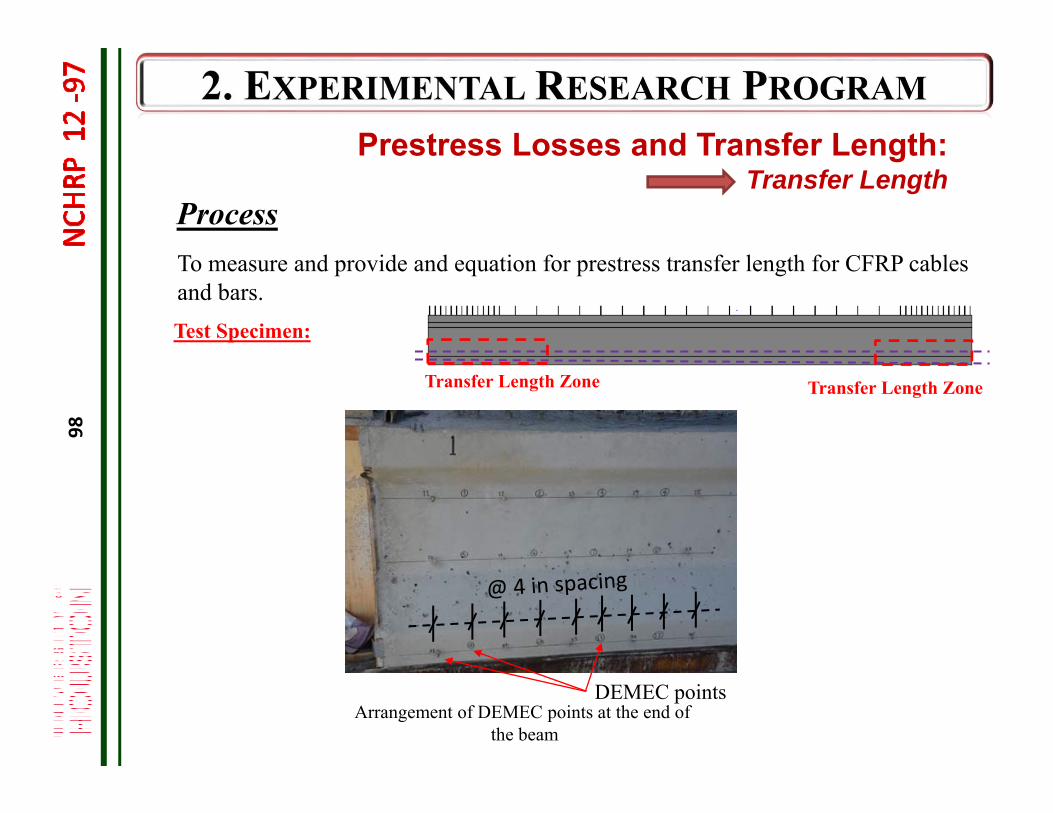
Test Specimen:
Process
Transfer Length Zone Transfer Length Zone
DEMEC pointsArrangement of DEMEC points at the end of
the beam
Prestress Losses and Transfer Length: Transfer Length
To measure and provide and equation for prestress transfer length for CFRP cables and bars.
99
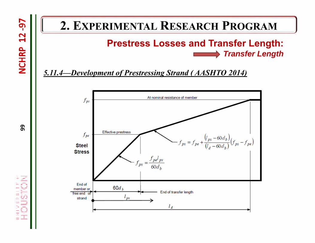
5.11.4—Development of Prestressing Strand ( AASHTO 2014)
Prestress Losses and Transfer Length: Transfer Length
100
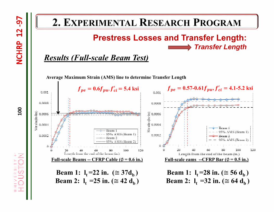
Full-scale Beams -- CFRP Cable (∅= 0.6 in.)
Beam 1: lt =22 in. (≅37db )Beam 2: lt =25 in. (≅42 db )
Results (Full-scale Beam Test)
Full-scale eams --CFRP Bar (∅= 0.5 in.)
Beam 1: lt =28 in. (≅56 db )Beam 2: lt =32 in. (≅64 db )
Average Maximum Strain (AMS) line to determine Transfer Length
0.6 , 5.4 ksi 0.57-0.61 , 4.1-5.2 ksi
Prestress Losses and Transfer Length: Transfer Length
101
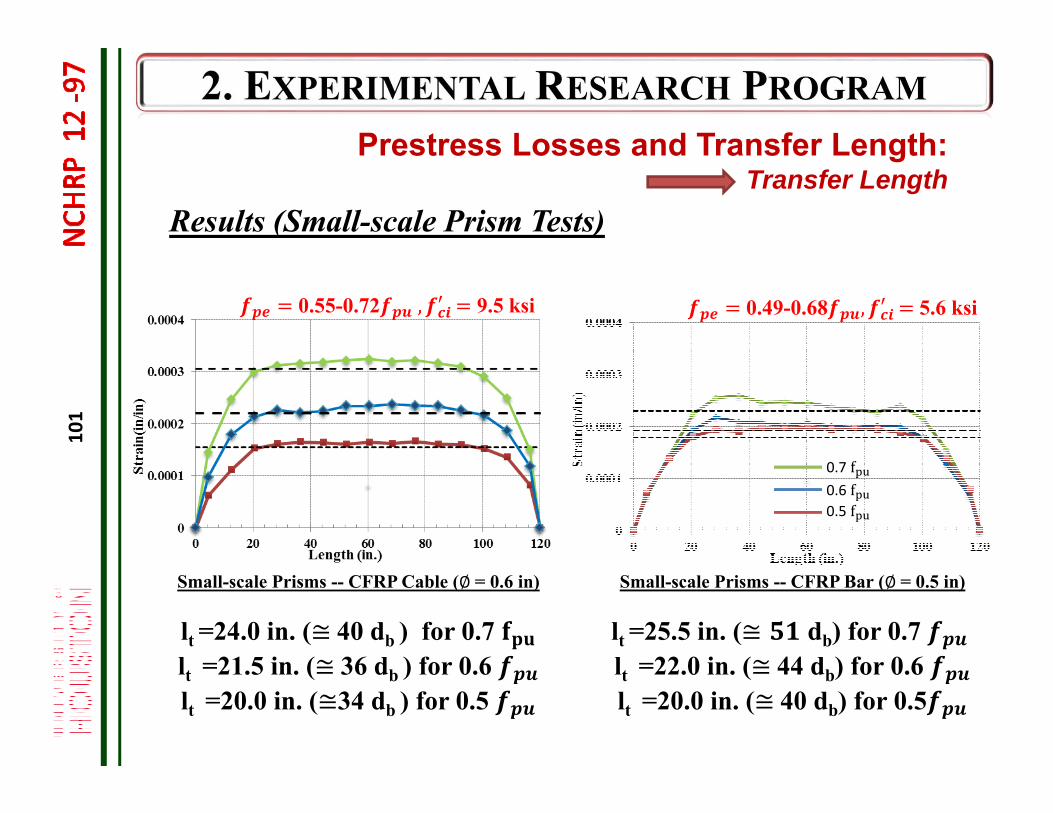
Small-scale Prisms -- CFRP Bar (∅= 0.5 in)
lt =25.5 in. (≅ db) for 0.7 lt =22.0 in. (≅44 db) for 0.6 lt =20.0 in. (≅40 db) for 0.5
Small-scale Prisms -- CFRP Cable (∅= 0.6 in)
lt =24.0 in. (≅40 db ) for 0.7 lt =21.5 in. (≅36 db ) for 0.6 lt =20.0 in. (≅34 db ) for 0.5
Results (Small-scale Prism Tests)
0.49-0.68 , 5.6 ksi0.55-0.72 , 9.5 ksi
0.5 f0.6 f0.7 f
Prestress Losses and Transfer Length: Transfer Length
102
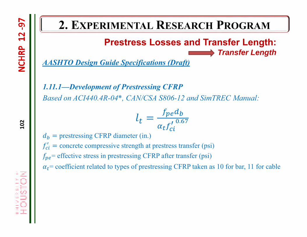
AASHTO Design Guide Specifications (Draft)
1.11.1—Development of Prestressing CFRPBased on ACI440.4R-04*, CAN/CSA S806-12 and SimTREC Manual:
.
prestressing CFRP diameter (in.)concrete compressive strength at prestress transfer (psi)
= effective stress in prestressing CFRP after transfer (psi)= coefficient related to types of prestressing CFRP taken as 10 for bar, 11 for cable
Prestress Losses and Transfer Length: Transfer Length
103
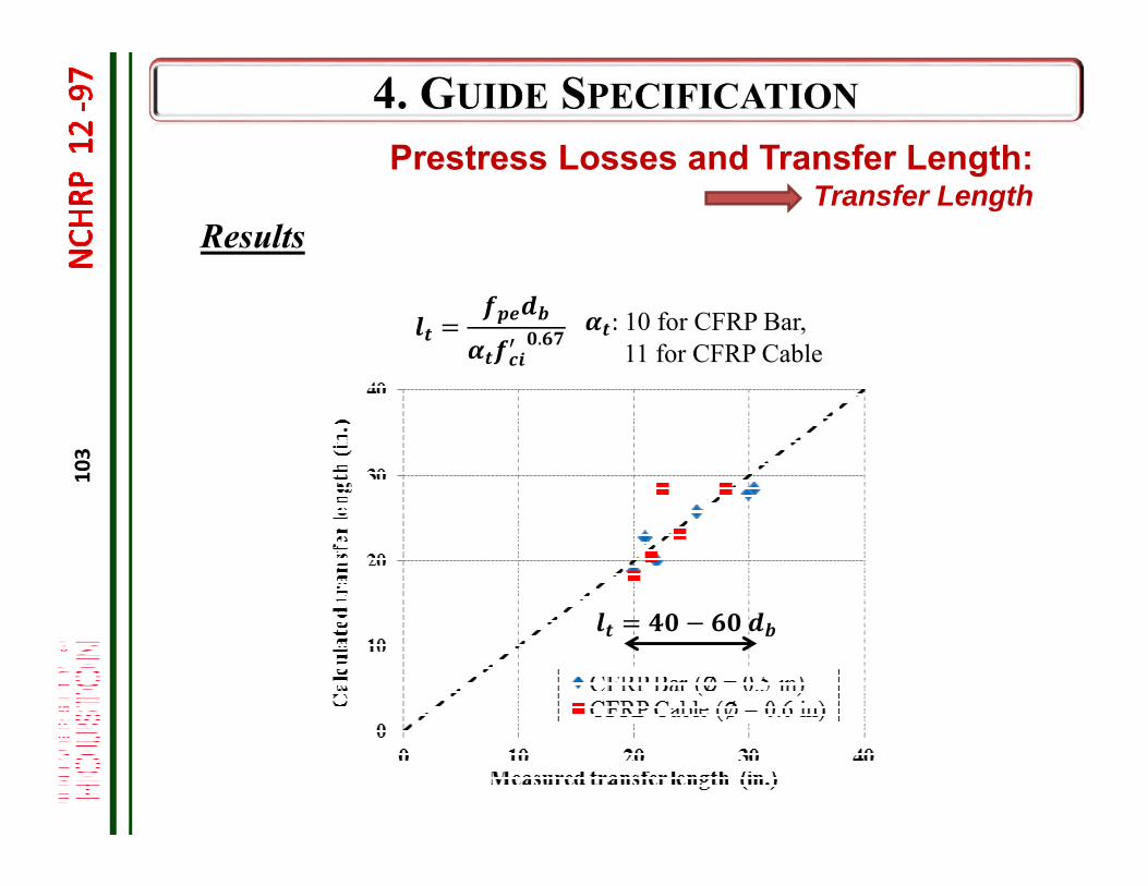
Results
.: 10 for CFRP Bar, 11 for CFRP Cable
Prestress Losses and Transfer Length: Transfer Length
104
Full-Scale TestingFlexural Behavior
Monotonic Loading Fatigue Loading Crack Patterns
105
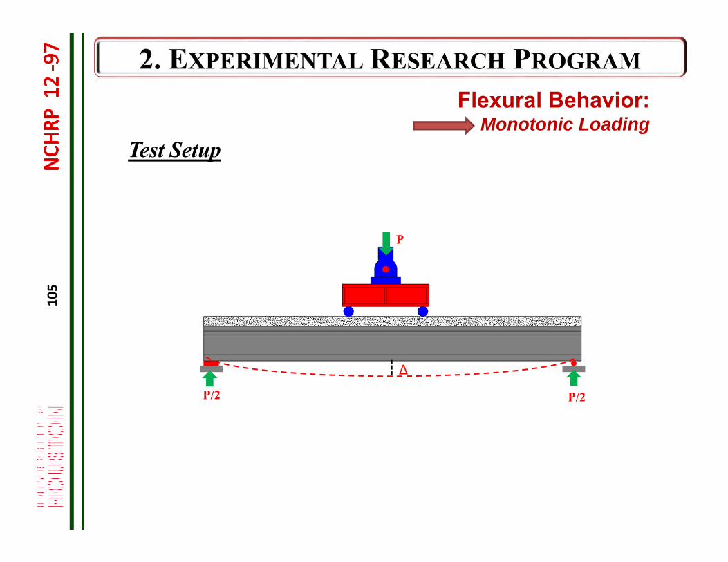
Test Setup
∆
P
P/2P/2
Flexural Behavior: Monotonic Loading
106
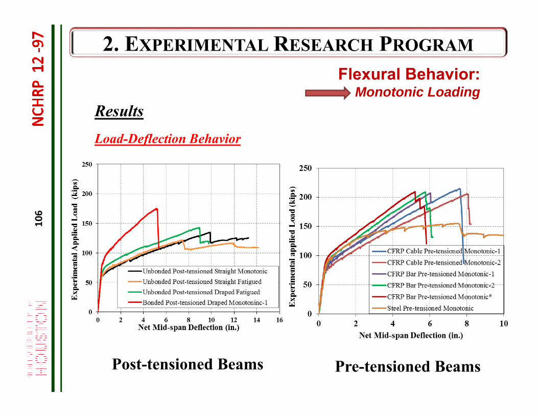
ResultsLoad-Deflection Behavior
Pre-tensioned Beams
Flexural Behavior: Monotonic Loading
Post-tensioned Beams
107
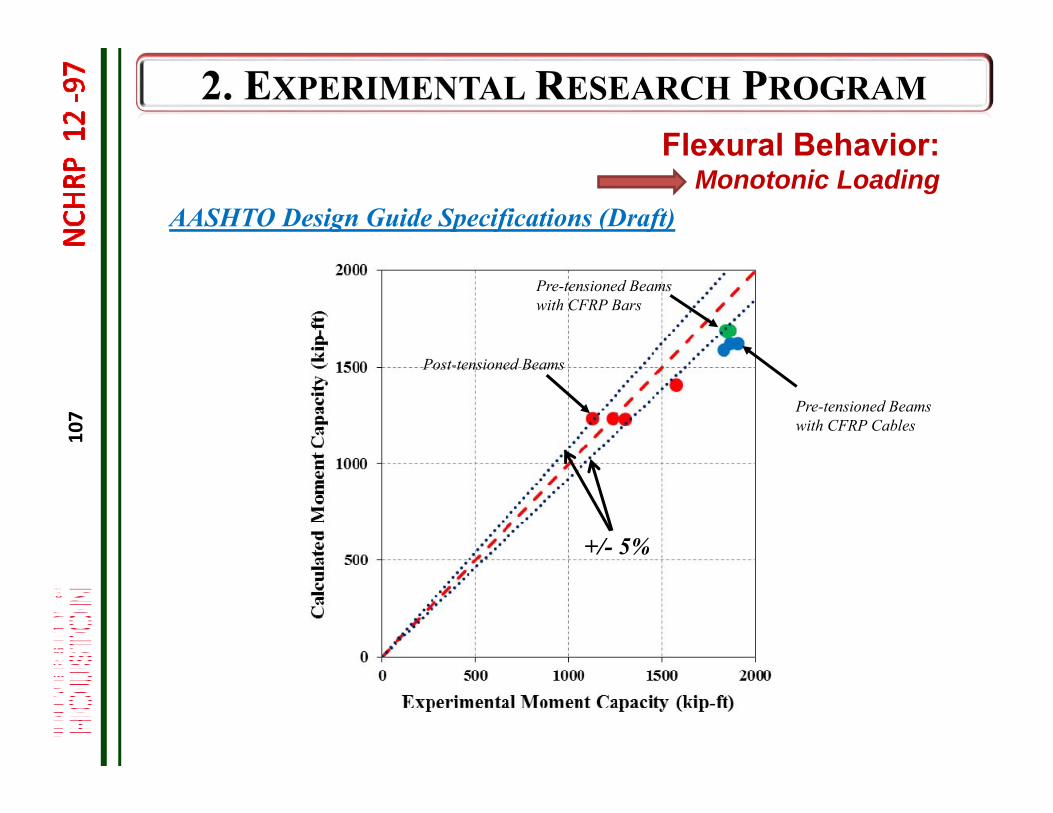
AASHTO Design Guide Specifications (Draft)
Pre-tensioned Beams with CFRP Cables
Pre-tensioned Beams with CFRP Bars
Post-tensioned Beams
Flexural Behavior: Monotonic Loading
+/- 5%
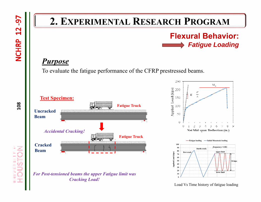
108
Uncracked Beam
Purpose
Test Specimen:
Fatigue Truck
Cracked Beam
To evaluate the fatigue performance of the CFRP prestressed beams.
Accidental Cracking!
Fatigue Truck
Load Vs Time history of fatigue loading
For Post-tensioned beams the upper Fatigue limit was Cracking Load!
Flexural Behavior: Fatigue Loading
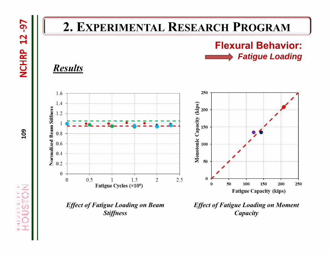
109
Results
Effect of Fatigue Loading on Moment Capacity
Flexural Behavior: Fatigue Loading
Effect of Fatigue Loading on Beam Stiffness
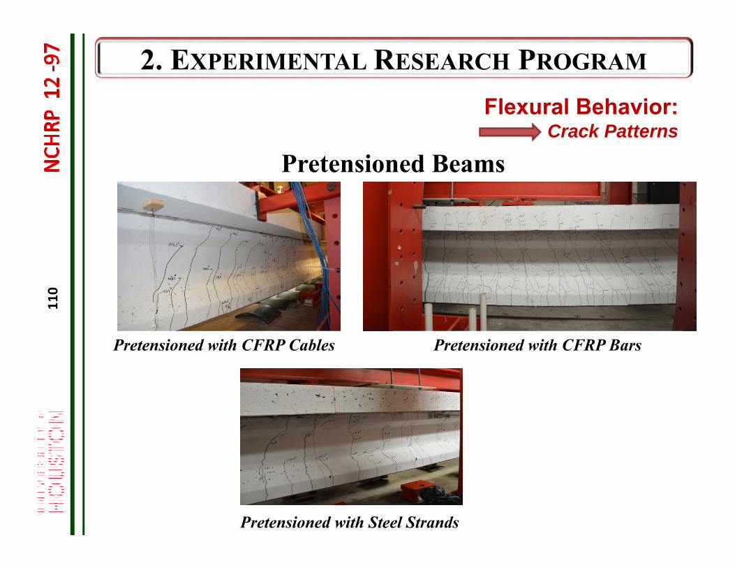
110
Pretensioned with CFRP Bars
Pretensioned Beams
Pretensioned with CFRP Cables
Pretensioned with Steel Strands
Flexural Behavior: Crack Patterns
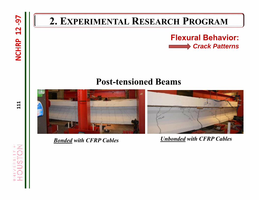
111
Bonded with CFRP Cables Unbonded with CFRP Cables
Flexural Behavior: Crack Patterns
Post-tensioned Beams

112
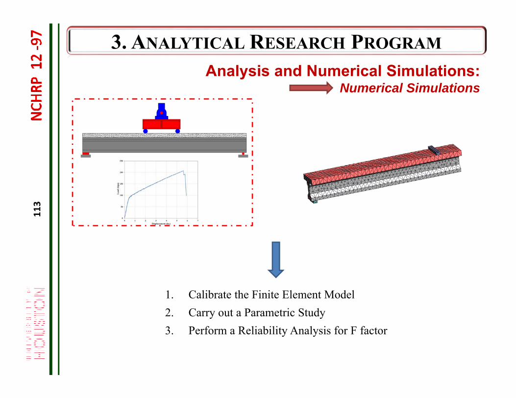
Analysis and Numerical Simulations
Numerical Simulations
Parametric Study and Reliability Analysis:
113
Analysis and Numerical Simulations: Numerical Simulations
1. Calibrate the Finite Element Model2. Carry out a Parametric Study3. Perform a Reliability Analysis for F factor
114
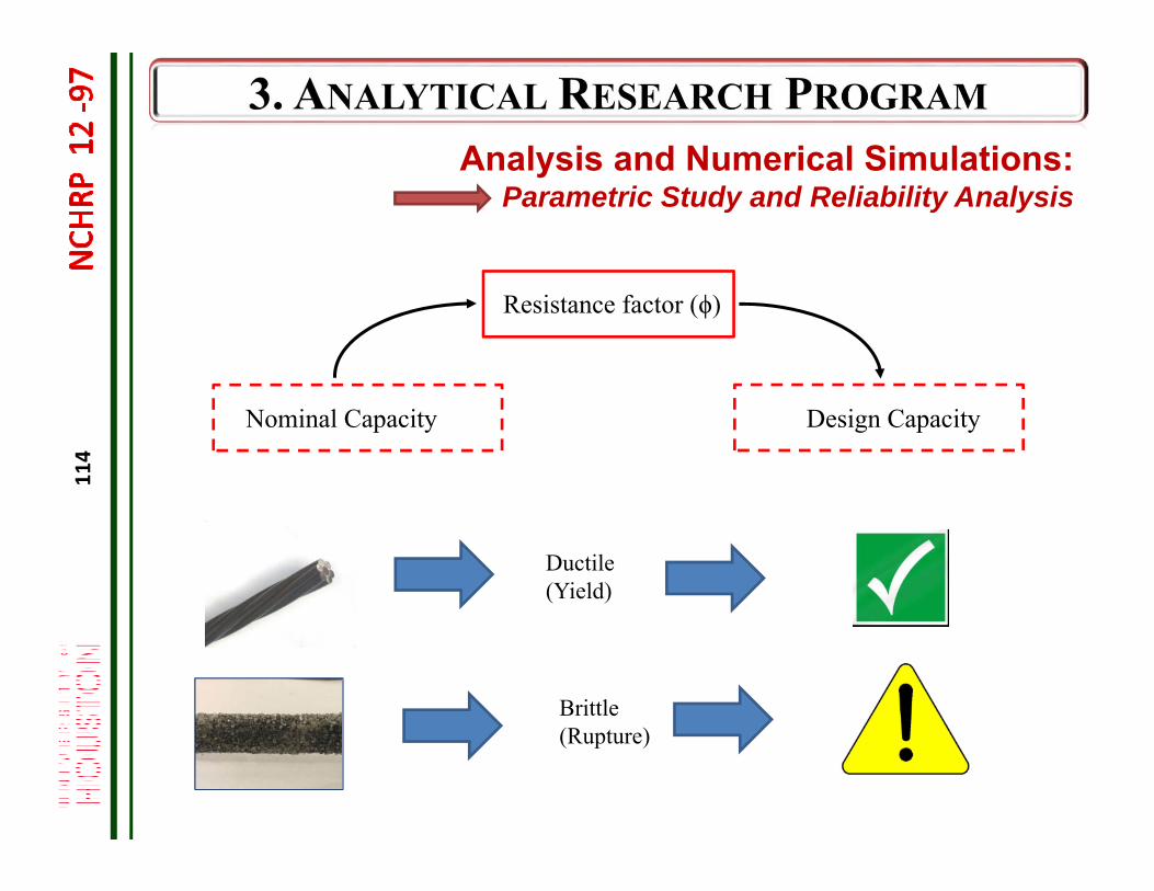
Design CapacityNominal Capacity
Resistance factor (ϕ)
Ductile (Yield)
Brittle (Rupture)
Analysis and Numerical Simulations: Parametric Study and Reliability Analysis
115
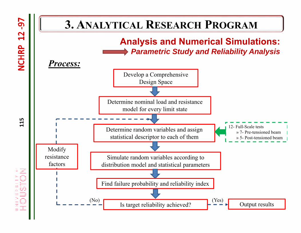
Develop a Comprehensive Design Space
Determine nominal load and resistance model for every limit state
Simulate random variables according to distribution model and statistical parameters
Find failure probability and reliability index
Is target reliability achieved?(No)
Output results
Determine random variables and assign statistical descriptor to each of them
(Yes)
Modify resistance
factors
12- Full-Scale tests» 7- Pre-tensioned beam» 5- Post-tensioned beam
Analysis and Numerical Simulations: Parametric Study and Reliability Analysis
Process:
116
Target Reliability Index:
• Adopted as 3.5 for steel prestressed bridges in AASHTO LRFD-2014• CFRP prestressed bridge girders differ from steel prestressed in terms
of ductility and redundancy• Given the nature of failure of CFRP prestressed bridges failing by
CFRP rupture (sudden failure with no residual capacity), the target reliability should be increased
• This can be addressed by using the load modifier (η) as specified in AASHTO LRFD-2014
• The load modifier is a multiplicative combination of three parameters namely ductility (ηD), redundancy (ηR), and operational classification (ηI)
η= ηD× ηR × ηI
• Generally, using η>1, relates to the target reliability higher that 3.5.
Analysis and Numerical Simulations: Parametric Study and Reliability Analysis
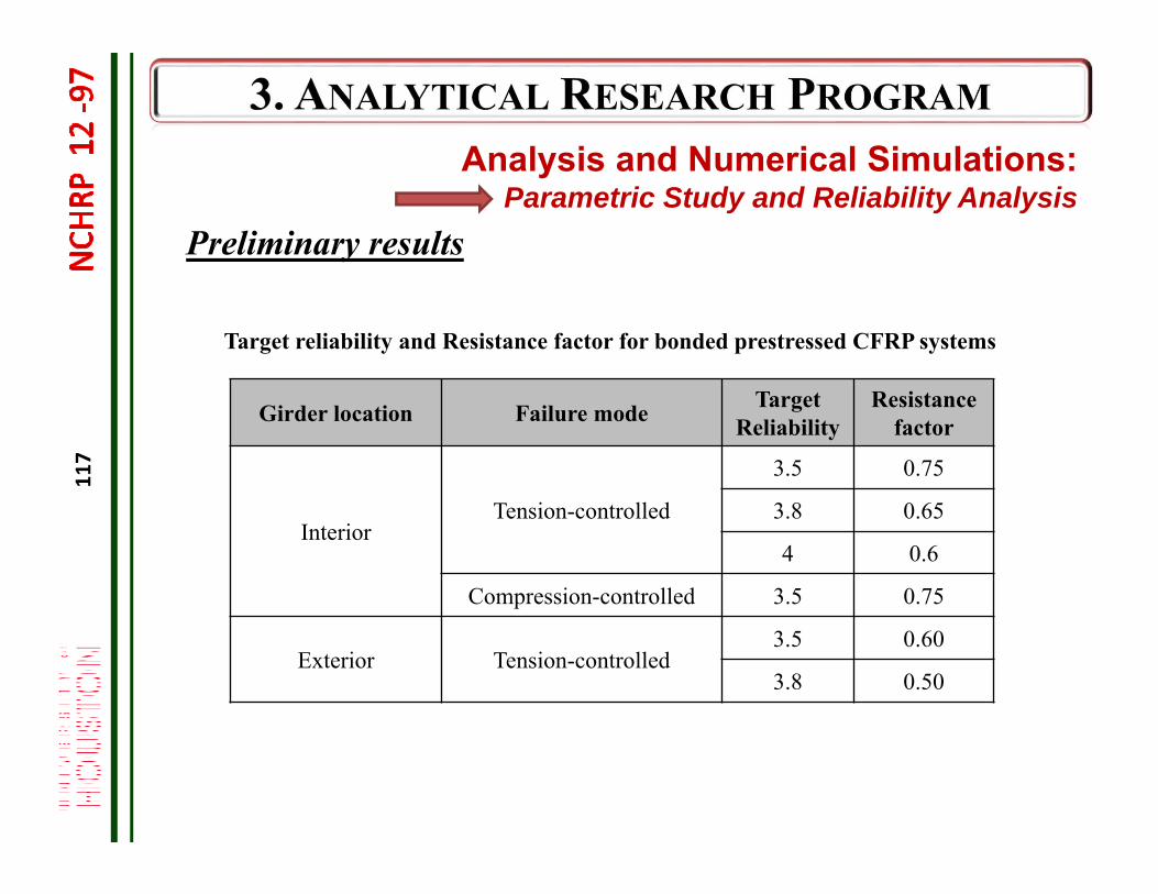
117
Preliminary results
Girder location Failure mode Target Reliability
Resistance factor
InteriorTension-controlled
3.5 0.75
3.8 0.65
4 0.6
Compression-controlled 3.5 0.75
Exterior Tension-controlled3.5 0.60
3.8 0.50
Target reliability and Resistance factor for bonded prestressed CFRP systems
Analysis and Numerical Simulations: Parametric Study and Reliability Analysis
118
A standalone document in AASHTO LRFD formatwith commentary
Contains two sections Design Guide Specifications (Section 1) CFRP Material Specifications (Section 2)
119
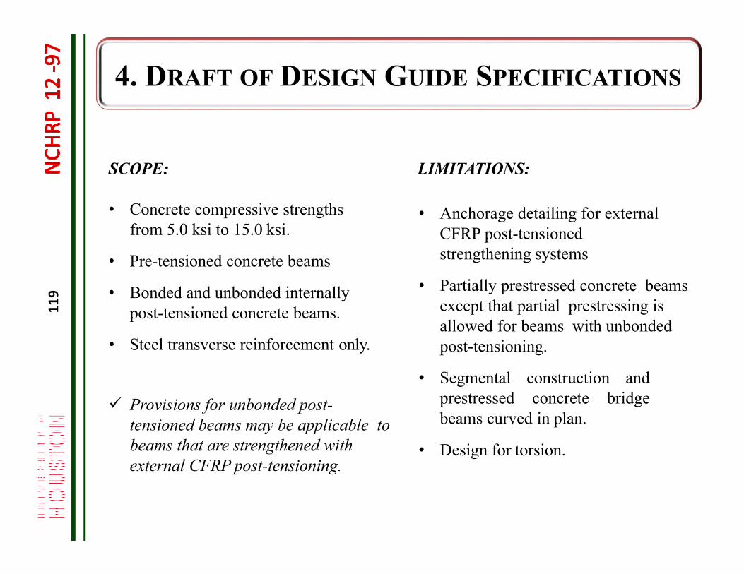
SCOPE:
• Concrete compressive strengths from 5.0 ksi to 15.0 ksi.
• Pre-tensioned concrete beams
• Bonded and unbonded internally post-tensioned concrete beams.
• Steel transverse reinforcement only.
Provisions for unbonded post-tensioned beams may be applicable to beams that are strengthened with external CFRP post-tensioning.
LIMITATIONS:
• Anchorage detailing for external CFRP post-tensioned strengthening systems
• Partially prestressed concrete beams except that partial prestressing is allowed for beams with unbondedpost-tensioning.
• Segmental construction andprestressed concrete bridgebeams curved in plan.
• Design for torsion.
120
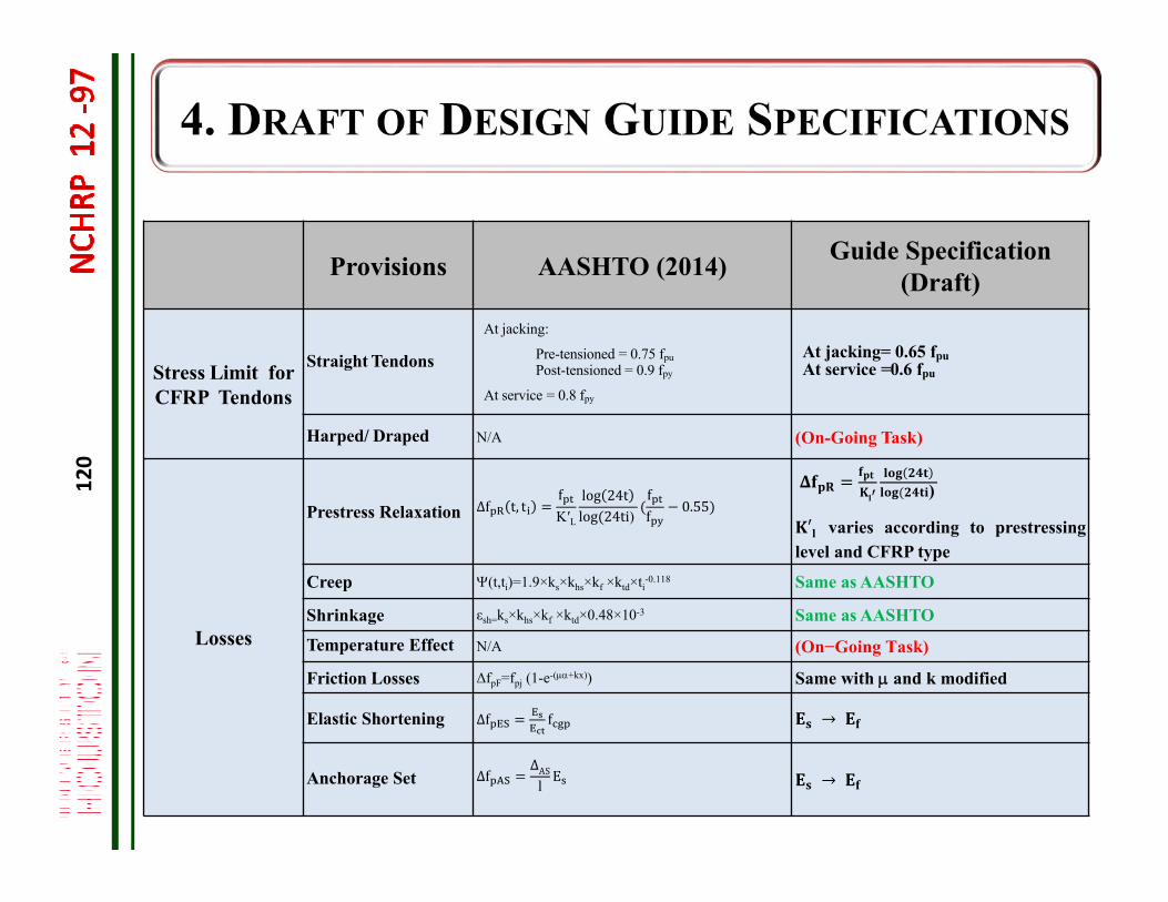
Provisions AASHTO (2014) Guide Specification (Draft)
Stress Limit for CFRP Tendons
Straight Tendons
At jacking:
Pre-tensioned = 0.75 fpuPost-tensioned = 0.9 fpy
At service = 0.8 fpy
At jacking= 0.65 fpuAt service =0.6 fpu
Harped/ Draped N/A (On-Going Task)
Losses
Prestress Relaxation Δf t, tfK′L
log 24tlog 24ti)
ff 0.55
)
′ varies according to prestressinglevel and CFRP type
Creep (t,ti)=1.9×ks×khs×kf ×ktd×ti-0.118 Same as AASHTO
Shrinkage εsh=ks×khs×kf ×ktd×0.48×10⁻³ Same as AASHTO
Temperature Effect N/A (On−Going Task)
Friction Losses ΔfpF=fpj (1-e-(+kx)) Same with and k modified
Elastic Shortening Δf f →
Anchorage Set ΔfΔASl E →
121
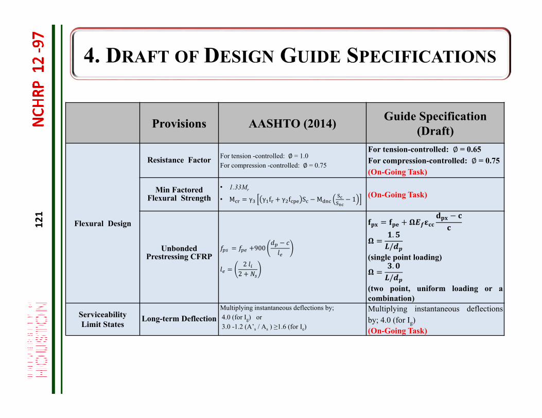
Provisions AASHTO (2014) Guide Specification (Draft)
Flexural Design
Resistance Factor For tension -controlled: ∅ = 1.0For compression -controlled: ∅ = 0.75
For tension-controlled: ∅ = 0.65For compression-controlled: ∅ = 0.75(On-Going Task)
Min FactoredFlexural Strength
• 1.33Mr
• M γ γ f γ f S M 1 (On-Going Task)
Unbonded Prestressing CFRP
900
22
./
(single point loading)./
(two point, uniform loading or acombination)
Serviceability Limit States
Long-term DeflectionMultiplying instantaneous deflections by;4.0 (for Ig) or3.0 -1.2 (A’s / As ) ≥1.6 (for Ie)
Multiplying instantaneous deflectionsby; 4.0 (for Ig)(On-Going Task)
122
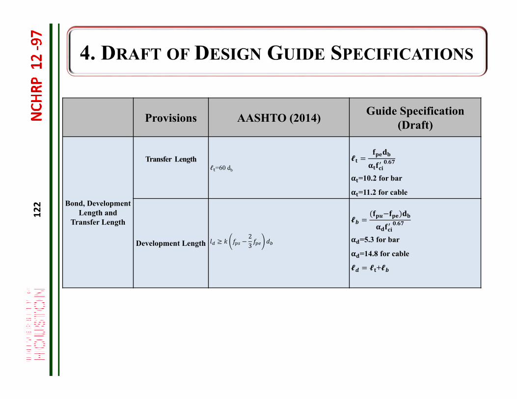
Provisions AASHTO (2014) Guide Specification (Draft)
Bond, Development Length and
Transfer Length
Transfer Lengthℓ =60 db
.
=10.2 for bar
=11.2 for cable
Development Length23
.
=5.3 for bar
=14.8 for cable
+
123
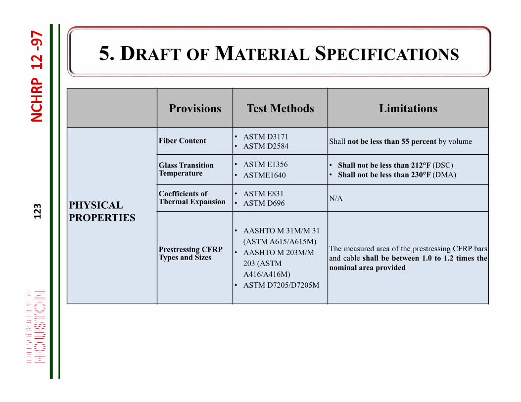
Provisions Test Methods Limitations
PHYSICAL PROPERTIES
Fiber Content • ASTM D3171• ASTM D2584 Shall not be less than 55 percent by volume
Glass Transition Temperature
• ASTM E1356• ASTME1640
• Shall not be less than 212°F (DSC)• Shall not be less than 230°F (DMA)
Coefficients of Thermal Expansion
• ASTM E831 • ASTM D696 N/A
Prestressing CFRP Types and Sizes
• AASHTO M 31M/M 31 (ASTM A615/A615M)
• AASHTO M 203M/M 203 (ASTMA416/A416M)
• ASTM D7205/D7205M
The measured area of the prestressing CFRP barsand cable shall be between 1.0 to 1.2 times thenominal area provided
124
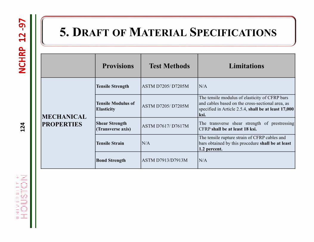
Provisions Test Methods Limitations
MECHANICAL PROPERTIES
Tensile Strength ASTM D7205/ D7205M N/A
Tensile Modulus of Elasticity ASTM D7205/ D7205M
The tensile modulus of elasticity of CFRP bars and cables based on the cross-sectional area, as specified in Article 2.5.4, shall be at least 17,000 ksi.
Shear Strength (Transverse axis) ASTM D7617/ D7617M The transverse shear strength of prestressing
CFRP shall be at least 18 ksi.
Tensile Strain N/AThe tensile rupture strain of CFRP cables and bars obtained by this procedure shall be at least 1.2 percent.
Bond Strength ASTM D7913/D7913M N/A
125
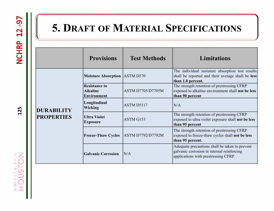
Provisions Test Methods Limitations
DURABILITY PROPERTIES
Moisture Absorption ASTM D570 The individual moisture absorption test resultsshall be reported and their average shall be lessthan 1.0 percent.
Resistance to Alkaline Environment
ASTM D7705/D7705M The strength retention of prestressing CFRP exposed to alkaline environment shall not be less than 90 percent
Longitudinal Wicking ASTM D5117 N/A
Ultra Violet Exposure ASTM G153
The strength retention of prestressing CFRP exposed to ultra violet exposure shall not be less than 95 percent
Freeze-Thaw Cycles ASTM D7792/D7792MThe strength retention of prestressing CFRP exposed to freeze-thaw cycles shall not be less than 95 percent.
Galvanic Corrosion N/A
Adequate precautions shall be taken to prevent galvanic corrosion in internal reinforcing applications with prestressing CFRP.
126
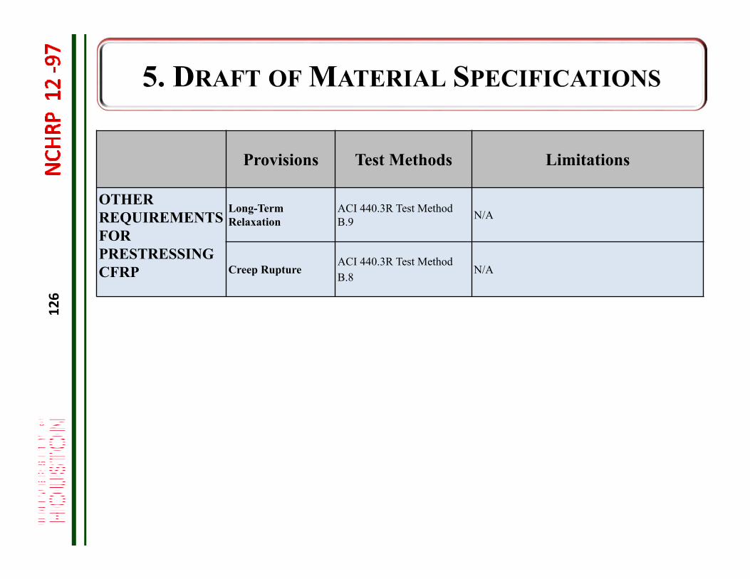
Provisions Test Methods Limitations
OTHER REQUIREMENTS FOR PRESTRESSING CFRP
Long-Term Relaxation
ACI 440.3R Test Method B.9 N/A
Creep Rupture ACI 440.3R Test Method B.8
N/A
127
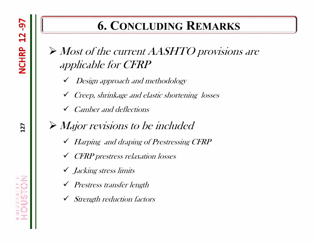
Most of the current AASHTO provisions are applicable for CFRP Design approach and methodology
Creep, shrinkage and elastic shortening losses
Camber and deflections
Major revisions to be included Harping and draping of Prestressing CFRP
CFRP prestress relaxation losses
Jacking stress limits
Prestress transfer length
Strength reduction factors
128
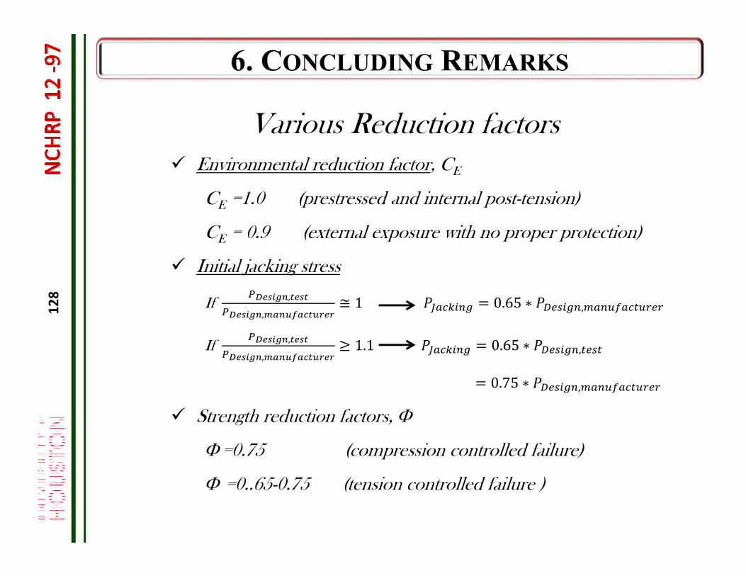
Various Reduction factors Environmental reduction factor, CE
CE =1.0 (prestressed and internal post-tension)
CE = 0.9 (external exposure with no proper protection)
Initial jacking stress
If ,
,≅ 1 0.65 ∗ ,
If ,
,1.1 0.65 ∗ ,
0.75 ∗ ,
Strength reduction factors,
=0.75 (compression controlled failure)
=0..65-0.75 (tension controlled failure )
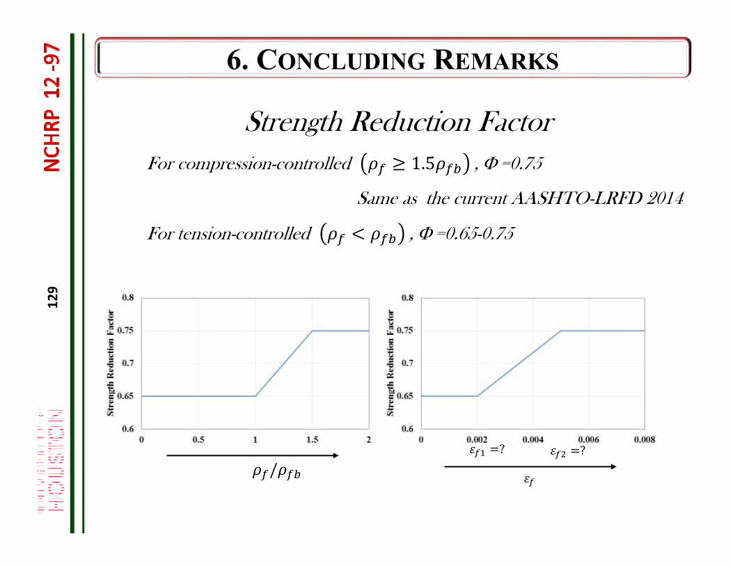
129
Strength Reduction FactorFor compression-controlled 1.5 , =0.75
Same as the current AASHTO-LRFD 2014
For tension-controlled , =0.65-0.75
/? ?

Research TeamDr. Mina Dawood, Associate Professor: UHDr. Bora Gencturk, Assistant Professor: UHMr. Prakash Poudel, PhD Candidate: UHMr. Hamidereza Tahsiri, PhD Candidate: UHMr. Mahmoud Reda, PhD Candidate: UHDr. Bora Acun, Postoctoral Fellow: UHMr. Barry Adkins, MS student: UHDr. Sami Rizkalla, Professor: NCSUDr. Henry Russell: Henry G. Russell, Inc.Dr. Wagdy Wassef: Modjeski and Masters, Inc.NCHRP12-97 panel members
Precast Plants and Material SuppliersPrecast/Prestressed Concrete InstituteHeldenfels Enterprises, Inc.East Texas PrecastTokyo Rope, Inc.Pultrall Inc.
13 0