Embed Size (px)
Citation preview

RW02 Concrete Masonry - Reinforced Soil Retaining Walls


TOP Woolooware Golf Course, NSW
RIGHT Devils Elbow Roadworks, South Australia
BELOW Gosford Bus/Rail Interchange, NSW

Segmental Concrete Reinforced Soil Retaining Walls –Design and Construction Guide
Concrete Masonry Association of Australia
Reposted with changes to Item 3 page 16, Item 11 page 17, Design Example 1, pp 25 to 27, Design Example 2, pp 34 to 36, December 2004
Reposted with additional explanations throughout, on Passive Pressure, Cohesion and Base Sliding, April 2004
Reposted with corrections to Disclaimer (below) and Drainage Fill Specification (page 42), May 2003
Reposted with corrections, April 2003
Second Edition (MA52) posted on web, March 2003
First published as MA50, March 2002
© 2003/04 Concrete Masonry Association of Australia
Except where the Copyright Act allows otherwise, no part of this publication may be reproduced, stored in a retrieval system in any form or transmitted by any means without prior permission in writing of both the Concrete Masonry Association of Australia.
The information provided in this publication is intended for general guidance only and in no way replaces the services of professional consultants on particular projects. No liability can therefore be accepted by the Concrete Masonry Association of Australia for its use.
It is the responsibility of the user of this Guide to check the Concrete Masonry Association of Australia web site (www.cmaa.com.au) for the latest amendments and revisions.
ISBN 0 909407 51 7

ABN 33 065 618 840
PO Box 370 Artarmon NSW 2064
T: 02 8448 5500 F: 02 9411 3801
E: [email protected] W: www.cmaa.com.au
The following organisations are recognised for their support and financial contribution towards this publication.
Cement and Concrete Association of Australia Leading Knowledge – Sharing Information www.concrete.net.au
MANUFACTURERS: Besser Masonry www.bessermasonry.com.au
Boral Masonry www.boral.com.au
C&M Brick Pty Ltd www.cmbrick.com.au
Nubrik Pty Ltd www.nubrik.com.au
Rocla Pavers & Masonry www.rocla.com.au
LICENSORS: Anchor Wall Systems www.anchorwall.com
Keystone Retaining Wall Systems www.keystonewalls.com
Allan Block Corporation www.allanblock.com
Rockwood Retaining Walls, Inc www.rockwoodretainingwalls.com
GEOGRID SUPPLIERS: Geofabrics Australasia Pty Ltd www.geofabrics.com.au
Maccaferri Pty Ltd www.maccaferri.com.au
Polyfabrics Australia Pty Ltd www.polyfabrics.com.au
Southern Geosynthetic Supplies Pty Ltd [email protected] www.huesker.com
Preface
This guide is a revised version of MA50–2002.
Standards Australia has published AS 4678(Ref 1) for the design and construction of earth retaining structures, including segmental concrete reinforced soil retaining walls. This standard encompasses the following features: ■ Limit state design that enable separate
consideration of stability, strength of components and serviceability
■ Partial load factors and partial material factors that permit the uncertainty and risk associated with each of the loads and materials to be assessed and taken into account
■ Compatibility with AS 1170 SAA Loading code(Ref 2)
■ Compatibility with the structures standards such as AS 3600 Concrete structures(Ref 3) and AS 3700 Masonry structures(Ref 4).
This guide provides a comprehensive approach to the design of segmental concrete reinforced soil retaining walls based on:■ The design and construction rules set out in
AS 4678■ An analysis method developed in the United States
and published by the National Concrete Masonry Association (NCMA)(Ref 5), and modified in part by the Concrete Masonry Association of Australia (CMAA) to fit Australian practice and the Australian Standard.
The scope of this guide is limited to the design of reinforced soil structures up to 6 metres high, consisting of concrete segmental facing units and geosynthetic grids, with a maximum wall slope of 15° from vertical. This guide does not apply to seawalls, water-retaining structures, unusual ground conditions (such as soft ground, land slips, steep sides or deeply inclined gullies) or to walls subject to sustained cyclic loading.
The guide includes:■ A description of the principal features of the
Australian Standard■ A description of the analysis method■ A comprehensive site investigation check list■ Design examples which demonstrates the use of
the Australian Standard and analysis method.
Segmental ConcreteReinforced Soil Retaining Walls
2

Segmental ConcreteReinforced Soil Retaining Walls
3
Contents
1 Introduction 4 1.1 General 4 1.2 Glossary 4 1.3 Behaviour of Concrete Reinforced Soil Retaining Walls 5 1.4 Importance of a Geotechnical Report 6 1.5 Safety and Protection of Existing Structures 6 1.6 Global Slip Failure 6 1.7 Differential Settlement 6 1.8 Importance of Drainage 6 1.9 Geogrid Spacing 7 1.10 Passive Pressure 7
2 Components 8 2.1 Drainage System 8 2.2 Concrete Facing Blocks 9 2.3 Reinforced Infill Soil 9 2.4 Geogrids 9 2.5 Adhesive 9
3 Design and Analysis Considerations 10 3.1 Limit State Design 10 3.2 Partial Loading and Material Factors 10 3.3 Load Combinations and Factors for the Stability of the Structure 10 3.4 Load Combinations and Factors for Strength of Components 11 3.5 Capacity Reduction Factors 12 3.6 Analysis Assumptions 12 3.7 Foundation Properties and Soil Model 12 3.8 Active Pressure 13 3.9 Passive Pressure 13 3.10 Bearing Failure 13 3.11 Sliding Failure 14 3.12 Wall Slope 14 3.13 Backfill Slope 14 3.14 Overturning 14 3.15 Tensile Strength of Geogrids 14 3.16 Anchorage of Geogrids Within the Soil Mass Beyond all Potential Failure Plane 14 3.17 Internal Sliding Resistance Within the Reinforced Soil Mass 14 3.18 Connection Strength of the Facing to the Geogrids 14 3.19 Bulging Resistance of the Facing Between the Geogrids 14 3.20 Facing Unit Strength 15 3.21 Cohesion 15
4 Design Procedure 15
5 References 21
6 Appendices 22 Appendix A – Site Investigation 23 Appendix B – Design Example Number 1 25 Appendix C – Design Example Number 2 34 Appendix D – Typical Specification 43

1 Introduction
1.1 GeneralFor many years reinforced concrete masonry cantilever retaining walls have been constructed with reinforced concrete masonry stems (steel reinforcement grouted into hollow concrete blockwork) and reinforced concrete footings.
Segmental concrete gravity retaining structures, consisting of concrete units dry-stacked against a soil slope and resisting overturning by virtue of their own weight, were introduced into Australia in the 1980s and rapidly became popular during the early 1990’s. This system provides very attractive embankment finishes, but its stability is limited by the geometry of the units and wall heights.
A revolutionary development during the 1990’s has been the incorporation of geogrids into the soil mass behind the structure to create segmental concrete reinforced soil structures. Such systems can be constructed several metres high and accommodate significant loads.
Figure 1.1 Reinforced Concrete Masonry Cantilever Retaining Walls
Figure 1.2 Segmental Concrete Gravity Retaining Walls
Figure 1.3 Segmental Concrete Reinforced Soil Retaining Walls
Segmental ConcreteReinforced Soil Retaining Walls
4
1.2 GlossaryLoads and limit states:Design life The time over which the structure is required to fulfil its function and remain serviceable.
Dead load The self-weight of the structure and the retained soil or rock.
Live load Loads that arise from the intended use of the structure, including distributed, concentrated, impact and inertia loads. It includes construction loads, but excludes wind and earthquake loads.
Wind load The force exerted on the structure by wind, acting on either or both the face of the retaining wall and any other structure supported by the retaining wall.
Earthquake load The force exerted on the structure by earthquake action, acting on either or both the face of the retaining wall and any other structure supported by the retaining wall.
Stability limit state A limit state of loss of static equilibrium of a structure, or part thereof, when considered as a rigid body.
Strength limit state A limit state of collapse or loss of structural integrity of the components of the retaining wall.
Serviceability limit state A limit state for acceptable in-service conditions. The most common serviceability states are excessive differential settlement and forward movement of the retaining wall.
Components:Concrete facing units Concrete blocks manufactured to provide an attractive, durable, stable face to a retaining wall. They commonly interlock or are connected by pins or connectors, and include provision for the securing of geogrids.
Geogrid Layers of metal or plastic material, which when constructed in horizontal planes in a soil mass, strengthen the soil. The most common geogrids are open "mesh" consisting of polyester, high-density polyethylene, polypropylene or steel.
Geotextile A permeable, polymeric material, which may be woven, non-woven or knitted. It is commonly used to separate drainage material from other soil.
Backfill material The natural soil or rock, intended to be retained by a retaining wall.
Foundation material The natural soil or rock material under a retaining wall.
Infill material The soil material, placed behind the retaining wall facing and strengthened by the geogrids.

Drainage material The crushed rock, gravel or similar material placed behind a retaining wall to convey groundwater away from the wall and foundations. It is commonly used in conjunction with other drainage media, such as agricultural pipes.
Soil types:Cohesive fill Naturally-occurring or processed materials with greater than 50% passing the 75 µm Australian standard sieve, a plasticity index of less than 30% and a liquid limit of less than 45%
Controlled fill Class I Soil, rock or other inert material that has been placed at a site in a controlled fashion and under appropriate supervision to ensure the resultant material is consistent in character, placed and compacted to an average density equivalent to 98% (and no test result below 95%) of the maximum dry density (standard compactive effort) for the material when tested in accordance with AS 1289.5.1.1. For cohesionless soils, material compacted to at least 75% density index is satisfactory.
Controlled fill Class II Soil, rock or other inert material that has been placed in specified layers and in a controlled fashion to ensure the resultant material is consistent in character, placed and compacted to an average density equivalent to 95% (and no test result below 92%) of the maximum dry density (standard compactive effort) for the material when tested in accordance with AS 1289.5.1.1. For cohesionless soils, material compacted to at least 65% density index is satisfactory. Generally the layer thickness is specified as a maximum of 300 mm.
Uncontrolled fill Soil, rock or other inert material that has been placed at a site and does not satisfy the materials included above.
Insitu material Natural soil, weathered rock and rock materials.
GW Well-graded gravel as defined by the Cassegrande extended classification system. Generally in the range of 2 to 60 mm, and graded such that the smaller particles pack into the spaces between the larger ones, giving a dense mass of interlocking particles with a high shear strength and low compressibility.
SW Well-graded sand as defined by the Cassegrande extended classification system. Generally in the range of 0.06 to 2 mm, and graded such that the smaller particles pack into the spaces between the larger ones, giving a dense mass of interlocking particles with a high shear strength and low compressibility.
GP Poorly-graded gravel as defined by the Cassegrande extended classification system. Generally in the range of 2 to 60 mm, and of a single size. This material has good drainage properties provided it is protected from infiltration by silts and clays.
1.3 Behaviour of Segmental Concrete Reinforced Soil Retaining WallsIf unrestrained, a soil embankment will slump to its angle of repose. Some soils, such as clays, have cohesion that enables vertical and near-vertical faces to remain partially intact, but even these may slump under the softening influence of ground water. When an earth retaining structure is constructed, it restricts this slumping. The soil exerts an active pressure on the structure, which deflects a little. It is then restrained by the friction and adhesion between the base and soil beneath, passive soil pressures in front of the structure (usually ignored) and the bearing capacity of the soil beneath the toe of the structure.
If water is trapped behind the retaining structure, it exerts an additional hydraulic pressure. This ground water also reduces the adhesion and bearing resistance.
If massive rock formations are present immediately behind the structure, these will restrict the volume of soil which can be mobilised and thus reduce the pressure.
Reinforced soil systems consist of a series of horizontal geogrids that have been positioned and pulled tight in a compacted soil mass, thus strengthening it and restricting its slump. The geogrids are strategically placed to intersect potential failure planes that are inclined from near the base of the wall, up at an angle (depending on the soil properties), to the top of the fill. The function of the geogrids is to “strengthen” the soil mass and they are “anchored” beyond the potential failure planes.
Local collapse and erosion of the front face is eliminated by fixing concrete segmental facing units to the exposed ends of the geogrids. However, the segmental concrete facing is not designed to “retain” the strengthened soil mass, which should be able to stand independently of the facing except for local effects. The connection spacing (and the geogrid spacing) must account for the local stability of the facing, including bulging and rotation above the top geogrid. The top course is normally bonded to the course below using epoxy cement.
A surface sealing layer and surface drainage system minimise the quantity of rainwater entering the soil mass. A sub-surface drainage system adjacent to the segmental concrete facing and (sometimes) beneath the wall reduce pore water pressures and thus reduce the tendency for local or global slip.
Thus, the essential features of a properly designed and constructed segmental concrete reinforced soil retaining wall are:■ Geogrids with adequate strength and anchorage ■ Adequate connection to the facing to provide local
stability■ A drainage system that will relieve pore water
pressures for the life of the structure.
Segmental ConcreteReinforced Soil Retaining Walls
5

1.4 Importance of a Geotechnical ReportThe design of a reinforced soil retaining wall includes two essential parts:■ Analysis of the proposed reinforced soil structure
and the adjacent ground for global slip, settlement, drainage and similar global considerations; and
■ Analysis and design of the reinforced soil structure itself.
These analyses must be based on an accurate and complete knowledge of the soil properties, slope stability, potential slip problems and groundwater. A geotechnical report by a qualified and experienced geotechnical engineer should be obtained.
Such a report must address the following considerations, as well as any other pertinent points not listed.■ Soil properties;■ Extent and quality of any rock, including floaters
and bedrock;■ Global slip and other stability problems;■ Bedding plane slope, particularly if they slope
towards the cut;■ Effect of prolonged wet weather and the
consequence of the excavation remaining open for extended periods;
■ Effect of ground water;■ Steep back slopes and the effect of terracing;■ Effect of any structures founded within a zone of
influence.
1.5 Safety and Protection of Existing StructuresWhenever soil is excavated or embankments are constructed, there is a danger of collapse. This may occur through movement of the soil and any associated structures by:■ rotation around an external failure plane that
encompasses the structure,■ slipping down an inclined plane,■ sliding forward, or■ local bearing failure or settlement.
These problems may be exacerbated by the intrusion of surface water or disruption of the water table, which increase pore water pressures and thus diminish the soil’s ability to stand without collapse.
The safety of workers and protection of existing structures during construction must be of prime concern and should be considered by both designers and constructors. All excavations should be carried out in a safe manner in accordance with the relevant regulations, to prevent collapse that may endanger life or property. Adjacent structures must be founded either beyond or below the zone of influence of the excavation. Where there is risk of global slip, for example around a slip plane encompassing the proposed retaining wall or other structures, or where there is risk of inundation by ground water or surface water, construction should not proceed until
the advice of a properly qualified and experienced Geotechnical Engineer has been obtained and remedial action has been carried out.
1.6 Global slip failureSoil retaining structures must be checked for global slip failure around all potential slip surfaces or circles.
Designers often reduce the heights of retaining walls by splitting a single wall into two (or more) walls, thus terracing the site. Whilst this may assist in the design of the individual walls, it will not necessarily reduce the tendency for global slip failure around a surfaces encompassing all or some of the retaining walls (Figure 1.4).
The designer should also take into account the effects of rock below or behind the structure in resisting slip failure.
Analysis for global slip is not included in this Guide and it is recommended that designers carry out a separate check using commercially available software.
1.7 Differential SettlementLocalised post-construction differential settlement should be limited to 1% of the height of the wall (Figure 1.5). However, it may be preferable to limit settlement to a lower figure, giving consideration to aesthetics (ie keeping the bedding planes level), in addition to the structural considerations
Techniques to reduce or control the effects of differential settlement include:■ Articulation of the wall (in discontinuing the normal
stretcher bond) at convenient intervals along the length;
■ Excavating, replacing and compacting areas of soft soil;
■ Limiting the stepping of the foundation and bottom course to a maximum of 200 mm.
1.8 Importance of DrainageThis Guide assumes that a properly functioning drainage system is effective in removing hydraulic pressure. If this is not the case, the designer will be required to design for an appropriate hydraulic load.
Based on an effective drainage system, it is common to use drained soil properties. For other situations, the designer must determine whether drained or undrained properties are appropriate. In particular, sea walls that may be subject to rapid draw-down (not covered in this guide) require design using undrained soil properties.
Segmental ConcreteReinforced Soil Retaining Walls
6

1.9 Geogrid SpacingHorizontal geogrids placed in the compacted infill soil serve to strengthen it, and should be located at centres not exceeding 600 mm (Figure 1.6).
The top section of the facing (above the top geogrid) should be stable. This can be achieved by:■ Placing the top geogrid at a depth of 300 to
400 mm below the top of the wall (excluding allowance for the capping block, if used), or
■ Tying the top of the wall to some other stable structure (eg concrete pavement) placed some distance from the face of the wall.
1.10 Passive PressureIn some circumstances, passive pressure could contribute marginally to the resistance to forward sliding. Because the soil in front of a retaining wall can be excavated, eroded or otherwise disturbed, it is strongly recommended that passive pressure in front of the wall be ignored in design.
Segmental ConcreteReinforced Soil Retaining Walls
7
Globalslip plane
Primaryglobal slip plane
Secondaryglobal slipplane
Wallheight,H
Differential settlement H/100
600 maximum
300to400
GeogridsCapping
Figure 1.4 Global Slip Failure
Figure 1.5 Differential Settlement
Figure 1.6 Geogrid Spacing

2 ComponentsA brief description of the principal components of segmental concrete reinforced soil retaining walls is set out below. The construction specification in Appendix D provides detailed specifications for each component
2.1 Drainage SystemThe drainage system consists of:■ A permeable wall facing system of segmental
concrete units; ■ A permeable drainage layer not less than
300 mm wide adjacent to the stem of the wall; ■ A slotted PVC agricultural pipe, with geofabric sock
if appropriate, or equivalent system, draining to the storm water system;
■ A catch drain capable of removing surface water from the top of the embankment. The base of the wall must also be adequately drained; and
■ A surface sealing layer that prevents the ingress of surface water into the fill behind the wall.
Drainage fill placed immediately behind the wall permits any ground water to percolate to the base of the wall where it is removed by the drainage pipe.
Drainage fill material should be:■ a single-sized gravel or crushed rock in the range
of 10 to 20 mm, designated GP, or■ a well-graded gravel, designated GW, with a
minimum particle size not less than 5 mm.
It is important that the drainage fill be free-draining, particularly in the lower parts of the wall. It should be positioned such that it delivers the water at the level of the drainage pipe, which must slope along the length of the wall.
To minimise the effect of clogging, the drainage pipe should be positioned in the drainage fill at a minimum uniform grade of 1 in 100. The pipe should be capable of removing the volume of water that may be present. The agricultural pipe should be connected to a PVC stormwater pipe and brought through the front face of the wall at intervals not exceeding 30 m. It should be connected to the storm-water system at the lower end
Segmental ConcreteReinforced Soil Retaining Walls
8
Slotted PVC ag. pipe draining stormwater at minimum 1 in 100 fall.Position pipe as close to wall as practical, allowing for fall
Drainage fill as per specification
Infill material as per specification
Geogrids as per specification
Excavation line
600 maximum
Compacted foundation material
Base material
Minimumwall slope
300 minimum400 maximum
Minimum fall1 in 100
Compacted clay or similar to seal surface.150 minimum thickness
Drain (minimum 1 in 100 fall)to permanent stormwater system
1
40
Optional capping unit
Top course (and capping if used)fixed with two-partepoxy adhesive
Concrete wall units
Geogrid to be justvisible in face of wall
Figure 2.1 Typical Components of Reinforced Soil Retaining Wall

of each run, where practical, and must drain positively away from base of the retaining wall.
The drainage pipe should be brought to the surface of the backfill at the upper end of each run to facilitate future flushing. It should be capped and its position marked.
The whole of the disturbed fill surface should be sealed by at least 150-mm of compacted clay and properly drained. Alternative means, such as bentonite layers or PVC membranes may be employed, provided they do not introduce potential slip planes into the surface material.
2.2 Concrete Facing BlocksConcrete facing units must be such that:■ They interlock with each other to provide a stable
facing. ■ They interlock with the geogrids, or alternatively
incorporate pins or other means of engaging the geogrids.
■ They are manufactured within tolerances such that the interlock can be achieved without distorting the face pattern.
■ They have sufficient strength to resist cracking in areas of minor differential settlement.
■ They are resistant to deterioration under the action of salts and ground water.
■ They are of a shape, size and mass that corresponds to those tested for connection strength and interface shear.
2.3 Reinforced Infill SoilReinforced infill material, ie the fill that is strengthened by the geogrids, should not contain large or sharp material that will damage the geogrids. It must also be capable of being fully compacted to form a solid mass reinforced by the geogrids. Well-graded gravel (GW) or well-graded sand (SW) is recommended.
2.4 GeogridsThe long-term strength and elongation of various geogrids depends on the material type and size. The design calculations also depend on the long-term test data that is available. Therefore the geogrids must be of the type and index strength nominated by the designer, and substitutions must not be made without the approval of the designer.
Geogrids must be a single length in the direction of design tension (ie into the embankment), not lapped, making provision for connection to the facing across the whole width of the facing and providing for the specified anchorage within the in designated anchorage zone.
Geogrids must cover the whole of the plan area behind the wall for the specified anchorage length and shall be lapped with adjacent sections in accordance with the manufacturer’s instructions. In the absence of manufacturer’s instructions, the overlying geogrids should be separated from the geogrid below by 100 mm of infill soil to prevent them from sliding over each other.
Commercially-available geogrids are, polyester, high-density polyethylene, polypropylene or steel.
2.5 AdhesiveThe adhesive used to bond the capping units and/or top-course units shall be capable of long-term adhesion in heat and wet conditions. A flexible two-part epoxy-based adhesive is recommended.
Segmental ConcreteReinforced Soil Retaining Walls
9
Highgroundwaterflow
Geocomposite orgravel drainsencapsulated ingeotextile
Continuousgeocomposite drainor gravel layerencapsulated in geotextile
Granular fill
Surface sealed and drain provided
Reinforcedsoil wall withdrainagesystem
DETAIL 'A'
(a) SITES WITH HIGH GROUND WATER FLOW
Low tomediumgroundwater flow
Geocomposite orgravel drainsGeocomposite
or gravel drains encapsulatedin geotextile, at regular intevals
Geocompositeor gravel drainsencapsulatedin geotextile
Subsoil drain withcorrect hydraulicconnection togeocompositeor gravel drains
Compactedclay
Surface sealed and drain provided
Free-draininggravel fill material
Geotextile layer
Compacted clay
Reinforcedsoil wall withdrainagesystem
DETAIL 'A'
(b) SITES WITH LOW TO MEDIUM GROUND WATER FLOW
DETAIL A
1 in 100 fall
1 in 100 fall
1 in 100 fall
Figure 2.2 Sub-Soil Drainage Systems

3 Design and Analysis Considerations
3.1 Limit State DesignThe following design limit states should be considered:■ stability of the structure as a whole subject to
ultimate factored loads,■ strengths of the various components subject to
ultimate factored loads,■ serviceability of the structure and its components
(including differential settlement and forward sliding and rotation) subject to service loads.
Important Note: Serviceability considerations are beyond the scope of this Guide. However, the designer is strongly advised to consider closely the appropriate serviceability limits and the methods of satisfying these requirements in practical design. One common method is to limit the stresses in the geogrid, foundation soil and other components as appropriate.
3.2 Partial Loading and Material FactorsAS 4678(Ref 1) provides partial load factors and partial material factors to be applied to characteristic loads and characteristic properties of various materials and components. These partial factors permit the uncertainty and risk associated with each of the loads and materials to be assessed and taken into account in the design.
The standard also provides rules for the combination of these factored loads and materials for separate limit states covering stability, strength of components and serviceability. These combinations are compatible with AS 1170(Ref 2) (except where indicated otherwise)(Note 1) and are compatible with the structures standards such as AS 3600(Ref 3) and AS 3700(Ref 4). However, some factors are not identical to their counterparts in AS 1170, for example, hydraulic loads and the means of combining soil properties to derive a dead load. These are discussed in more detail below.
3.3 Load Combinations and Factors for Stability of the StructureThe following load combinations and factors should be applied when checking the stability of the structure. This includes analysis for both external and internal stability.
External stability:■ Global slip■ Overturning■ Bearing capacity of the foundation under the toe of
the base■ Sliding resistance of the foundation under the base
Internal stability:■ Internal sliding resistance within the reinforced soil
mass■ Bulging resistance of the facing between the
geogrids■ Anchorage of the geogrids within the soil mass
beyond any potential failure plane■ Connection strength of the facing to the geogrids.
(Note 2)
(i) 1.25 GC + 1.5 QC < 0.8 GR + (Φ R)
(ii) 1.25 GC + ψc QC + WCu < 0.8 GR + (Φ R)
(iii) 1.25 GC + ψc QC + 1.0 FCeq < 0.8 (G + ψcQ)R + (Φ R)
Where: GC = parts of the dead load tending to cause instability. This includes: the weight of the retained soil, which causes horizontal pressures on the retained soil block, thus tending to cause forward sliding, bearing failure, or overturning, or the weight of the infill soil.
QC = parts of the live load tending to cause instability. This includes all removable loads such as live loadings applied from adjacent buildings an allowance for the temporary stacking of soil of not less than 5 kPa. Where a live load can be applied on the retained soil, but not on the infill, the resulting active pressure will tend to cause overturning, but the gravity load will not resist overturning. For example, a road pavement may be placed on the backfill, but not fully on the infill. In this case, the appropriate factors should be applied. WC
u = parts of the wind load tending to cause instability.If the wind load is applied to some supported structure such as a
Segmental ConcreteReinforced Soil Retaining Walls
10
NOTES:
1 At the time of publication of this Guide, Standards Australia is preparing a revised loading standard. When that standard is published, it will be necessary to re-examine AS 4678 and this Guide for compatability with any loads and load factors.
2 Design for bearing capacity, external sliding resistance, internal sliding resistance, bulging resistance and anchorage all involve the factoring down of the soil properties (density, friction angle and/or cohesion) which are providing the resistance to instability. Design for connection strength involves the factoring down of the facing material weight (and thus friction resistance) which is assumed to be the principal property resisting disengagement of the connections.

building or a fence, the effect could be significant. However, for the case of wind on only the face of the wall, the factors are such that load combination (ii) involving wind loading, will not be the governing case when the effect due to wind, WC
u is less than (1.5 - ψc) times the effect due to live load, QC. For example for a wall that does not support another exposed structure and for a minimum live load surcharge of QC = 5 kPa, an active pressure coefficient of Ka = 0.3 and a live load combination factor of ψc = 0.6, a wind suction load on the face of the retaining wall less than 1.35 kPa will not be the governing case.
FCeq = parts of the earthquake load tending to
cause instability. For earthquake categories Ae and Be, design for static loads without further specific analysis is deemed adequate. For earthquake category Ce, a dead load factor of 1.5 (instead of 1.25) is used and specific design for earthquake is not required. For earthquake categories De and Ee, the structures should be designed and analysed in accordance with the detailed method set out in Appendix I of AS 4678
GR = parts of the dead load tending to resist instability. This includes the self weight of the structure and the weight of soil in front of the structure. It is common to exclude consideration of passive pressure.
ΦR = the factored design capacity of the structural component. This includes bearing capacity, sliding resistance, pull-out strength etc.
ψc = live load combination factor. This is taken as 0.4 for parking or storage and 0.6 for other common applications on retaining walls.
In addition to soil retained behind the structure, stacked materials, additional soil and vehicles may exert pressures on the wall. AS 4678 requires a minimum live load surcharge of 5 kPa.
The distribution of live loads and the corresponding load factors should be considered carefully by the design engineer.
Since these are matters that go to the basis of AS 4678 and AS 1170.1, it is not appropriate for this Guide to make recommendations, apart from suggesting that the following questions be considered:
■ Does the live load factor for the particular load case include provision for variation in the placement of the live load?
■ For external stability analysis, should a live load be placed only on the retained soil and omitted from the infill material? In such a case, are the load factors given in AS 4678 appropriate?
■ Alternatively, may a uniform live load be placed across both the retained soil and infill material? If so, what are the appropriate load factors?
3.4 Load Combinations and Factors for Strength of ComponentsThe following load combinations and factors should be applied when checking the strength of the structure components. This includes analysis for:■ Tensile strength of the geogrids■ Strength of any associated components.
(i) 1.25 G + 1.5 Q
(ii) 1.25 G + Wu + ψc Q
(iii) 1.25 G + 1.0 Feq + ψc Q
(iv) 0.8 G + 1.5 Q
(v) 0.8 G + Wu
(vi) 0.8 (G + ψc Q) + 1.0Feq
Where: G = dead load
Q = live load
Wu = wind load
Feq = earthquake load
ψc = live load combination factor taken as 0.4 for parking or storage and 0.6 for other common applications on retaining walls.
See further explanation in Clause 3.3.
Segmental ConcreteReinforced Soil Retaining Walls
11
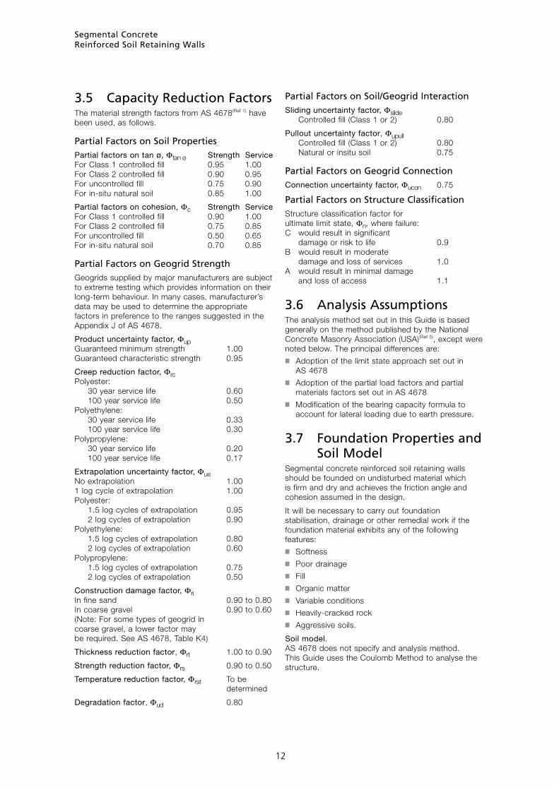
3.5 Capacity Reduction FactorsThe material strength factors from AS 4678(Ref 1) have been used, as follows.
Partial Factors on Soil PropertiesPartial factors on tan ø, Φtan ø Strength Service For Class 1 controlled fill 0.95 1.00 For Class 2 controlled fill 0.90 0.95 For uncontrolled fill 0.75 0.90 For in-situ natural soil 0.85 1.00
Partial factors on cohesion, Φc Strength Service For Class 1 controlled fill 0.90 1.00 For Class 2 controlled fill 0.75 0.85 For uncontrolled fill 0.50 0.65 For in-situ natural soil 0.70 0.85
Partial Factors on Geogrid StrengthGeogrids supplied by major manufacturers are subject to extreme testing which provides information on their long-term behaviour. In many cases, manufacturer’s data may be used to determine the appropriate factors in preference to the ranges suggested in the Appendix J of AS 4678.
Product uncertainty factor, Φup Guaranteed minimum strength 1.00 Guaranteed characteristic strength 0.95
Creep reduction factor, Φrc Polyester: 30 year service life 0.60 100 year service life 0.50 Polyethylene: 30 year service life 0.33 100 year service life 0.30 Polypropylene: 30 year service life 0.20 100 year service life 0.17
Extrapolation uncertainty factor, Φue No extrapolation 1.00 1 log cycle of extrapolation 1.00 Polyester: 1.5 log cycles of extrapolation 0.95 2 log cycles of extrapolation 0.90 Polyethylene: 1.5 log cycles of extrapolation 0.80 2 log cycles of extrapolation 0.60 Polypropylene: 1.5 log cycles of extrapolation 0.75 2 log cycles of extrapolation 0.50
Construction damage factor, Φri In fine sand 0.90 to 0.80 In coarse gravel 0.90 to 0.60 (Note: For some types of geogrid in coarse gravel, a lower factor may be required. See AS 4678, Table K4)
Thickness reduction factor, Φrt 1.00 to 0.90
Strength reduction factor, Φrs 0.90 to 0.50
Temperature reduction factor, Φrst To be determined
Degradation factor, Φud 0.80
Partial Factors on Soil/Geogrid InteractionSliding uncertainty factor, Φslide Controlled fill (Class 1 or 2) 0.80
Pullout uncertainty factor, Φupull Controlled fill (Class 1 or 2) 0.80 Natural or insitu soil 0.75
Partial Factors on Geogrid ConnectionConnection uncertainty factor, Φucon 0.75
Partial Factors on Structure ClassificationStructure classification factor for ultimate limit state, Φn, where failure: C would result in significant damage or risk to life 0.9 B would result in moderate damage and loss of services 1.0 A would result in minimal damage and loss of access 1.1
3.6 Analysis AssumptionsThe analysis method set out in this Guide is based generally on the method published by the National Concrete Masonry Association (USA)(Ref 5), except were noted below. The principal differences are:■ Adoption of the limit state approach set out in
AS 4678■ Adoption of the partial load factors and partial
materials factors set out in AS 4678■ Modification of the bearing capacity formula to
account for lateral loading due to earth pressure.
3.7 Foundation Properties and Soil ModelSegmental concrete reinforced soil retaining walls should be founded on undisturbed material which is firm and dry and achieves the friction angle and cohesion assumed in the design.
It will be necessary to carry out foundation stabilisation, drainage or other remedial work if the foundation material exhibits any of the following features:■ Softness■ Poor drainage■ Fill■ Organic matter■ Variable conditions■ Heavily-cracked rock■ Aggressive soils.
Soil model. AS 4678 does not specify and analysis method. This Guide uses the Coulomb Method to analyse the structure.
Segmental ConcreteReinforced Soil Retaining Walls
12

3.8 Active PressureIn response to soil pressure, the wall will move away from the soil, thus partially relieving the pressure. This reduced presure is the active pressure. The Coulomb equation for active pressure coefficient (Ka) can account for slope of the wall and slope of the backfill. The slope of the wall should be restricted to less than external angle of friction (d) to ensure that there is no upward component of earth pressure which would reduce sliding resistance (ie the equation applies when wall slope is less than 15° for good quality granular backfills in contact with concrete).
pa = active pressure on the wall at depth of H = Ka γ H
Where:
Ka = active pressure coefficient
cos2(φ + ω)
=
cos2 ω cos(ω - d) 1+ sin(φ + d) sin(φ - β) 2
cos(ω - d) cos(ω + β)
φ = factored value of internal friction angle (degrees)
d = external friction angle (degrees)
= 2φ
at interface between soil and facing 3
or, at interface between two soil layers, the smaller of the friction angles
or, at any interface with filter fabric, the external friction angle should be taken from test data. If no data is available, it should be assumed to be zero.
ω = slope of the wall (degrees)
β = slope of the backfill (degrees)
γ = factored value of soil density (kN/m3)
H = height of soil behind the wall (m)
3.9 Passive PressureIf the structure pushes into the soil, as is the case at the toe of a retaining wall, the resistance by the soil is greater than the pressure at rest. This is the passive pressure, given by the following equation. If the soil in front of the toe is disturbed or loose, the full passive pressure may not be mobilised. The common practice of assuming zero for passive pressure with reinforced soil structures has been adopted in this Guide.
pp = passive soil pressure (kPa) = Kp γ He
Where: Kp = passive pressure coefficient
= 1 + sin φ
1 - sin φ
φ = factored value of internal friction angle (degrees)
γ = factored value of soil density (kN/m3)
He = depth of undisturbed soil to underside of base or wall units as appropriate (m)
3.10 Bearing FailureAs soil and water pressure are applied to the rear face of the structure, it will tilt forward and the soil under the toe is subjected to high bearing pressures. The following theoretical approach is based on a Meyerhof shear failure formula. This gives consideration to footing width, footing tilt and angle of applied load and is explained in a paper by Vesic titled Bearing Capacity of Shallow Footings in the Foundation Engineering Handbook(Ref 6).
Q = Bearing capacity of the foundation (kN)
= qav LB
Where:
qav = average bearing capacity based on factored soil properties (kPa)
B = length of reinforced soil block
e = eccentricity of vertical loading
LB = design base width (m) based on the Meyerhof approach to account for eccentric load = B - 2e
c = factored value of drained cohesion (kPa)
φ = factored value of friction angle (degrees)
γ = factored value of soil density (kN/m3)
He = depth of undisturbed soil to the underside of the base or wall units as appropriate (m)
Nc = (Nq - 1) cot φ
Nq = eπ tan φ tan2 [π/4 + φ/2]
Nγ = 2 (Nq + 1) tan φ
Shape factors: ζc = 1.0 for rectangular base
ζq = 1.0 for rectangular base
ζγ = 1.0 for rectangular base
Factors for inclined load: ζci = ζqi - (1 - ζqi ) / (Nc tan φ)
ζqi = {1 - P* / [Q* + (LB c cot φ)]}2
ζγi = {1 - P* / [Q* + (LB c cot φ)]}3
Factors for sloping bases: ζct = ζqt - (1 - ζqt) / (Nc tan φ) = 1.0 for level base
ζqt = (1 - α tan φ)2 = 1.0 for level base
ζγt = (1 - α tan φ)2 = 1.0 for level base
Q* = vertical load based on factored loads and soil properties
P* = horizontal load based on factored loads and soil properties
α = angle of base tilt in radians = zero for level base
Segmental ConcreteReinforced Soil Retaining Walls
13
= c Nc ζc ζci ζct + γ He Nq ζqζqi ζqt + 0.5 γ B Nγ ζγ ζγi ζγt

3.11 Sliding FailureAs soil and water pressure are applied to the rear face of the structure, the structure may slide forward. Such sliding action is resisted by the friction between the foundation material and the structure and the passive resistance of any soil in front of the toe or is subjected to high bearing pressures. Because the soil in front of a retaining wall can be excavated, eroded or otherwise disturbed, it is strongly recommended that passive pressure in front of the wall be ignored in design.
F = Sliding resistance based on factored characteristic soil properties
= Friction + adhesion + passive resistance
= Q* tan d + c B + Kp 0.5 γ He2
= Q* tan d
(In this Guide, passive resistance, base adhesion and cohesion are taken as zero. The sliding resistance of the units over the bearing pad material may different from the sliding resistance of the infill material over the bearing pad or foundation, but the difference is generally small and its effect on total sliding resistance is usually neglected. The designer should consider the validity of this approximation.)
Where:
Q* = vertical load based on factored loads and soil properties
d = external friction angle of the soil calculated from the factored internal friction angle, assuming a smooth base-to-soil interface (if a rough base-to-soil interface is present, a friction angle of φ may be used)
B = actual base width (m)
c = factored value of drained cohesion (kPa)
Kp = passive pressure coefficient
γ = factored value of soil density (kN/m3)
He = depth of undisturbed soil to underside of base or wall units as appropriate (m).
3.12 Wall SlopeThis Guide does not cover the design of revetments or walls with a lean back of more than 20° from vertical.
3.13 Backfill SlopeThe designer should consider the stability of the slope of any backfill placed behind and above the wall. The slope should not exceed an angle whose tangent is given by dividing the tangent of the design friction angle by an appropriate factor.
3.14 OverturningAS 4678 does not specify an analysis method for overturning.
This guide considers overturning about the toe of the structure (which could be some distance below the finished soil level at the toe). It allows for a sloping wall and sloping fill. Because the base materials are not rigid, there can be no upward movement of the heel as so-called “rotation” about the toe commences. Therefore, there is no development of friction at the rear of the soil mass.
3.15 Tensile Strength of the GeogridsAS 4678 does not specify an analysis method. Design is based on the force calculated using the average pressure at the midpoint of the contributory area based on measurements vertically down from the top of the wall.
3.16 Anchorage of the Geogrids Within the Soil Mass Beyond all Potential Failure PlaneAS 4678 does not specify an analysis method. Design is based on a minimum of 300-mm anchorage length beyond the failure plane, drawn from the heel of the bottom unit. An overall lower limit on the length of geogrid, measured from the front face of the wall, is set at 0.7 times wall height.
3.17 Internal Sliding Resistance Within the Reinforced Soil MassAS 4678 does not specify an analysis method. Design is based on the resistance to slip calculated along lengths defined within the reinforced soil mass.
3.18 Connection Strength of the Facing to the GeogridsAS 4678 requires that the connection of the bottom geogrid to the facing be designed for 100% of the load in the corresponding geogrid and the top connection be designed for 75%.
3.19 Bulging Resistance of the Facing Between the GeogridsAS 4678 does not specify an analysis method. Design is based on sliding due to incremental shear forces between reinforcement grids.grids Localised bending is not a problem, because the vertical component of soil force resists the uplift of the units necessary to allow this type of failure to occur.
Segmental ConcreteReinforced Soil Retaining Walls
14

Segmental ConcreteReinforced Soil Retaining Walls
15
3.20 Facing Unit StrengthConcrete blocks should have a characteristic unconfined compressive strength, f’uc, of at least 10 MPa in accordance with AS 4456.4(Ref 7), and calculated in accordance with AS 3700 Appendix B, to ensure that there is sufficient integrity to tolerate minor movement.
3.21 CohesionCohesion is the property of a cohesive soil that:■ permits a cut surface to stand vertically (up to a
particular height) without additional support from a wall, and
■ provides significant contribution to bearing capacity.
For determining active forces on retaining walls, this Guide recommends that cohesion of retained soils should be assumed to be zero and recommends against the use of the Rankine-Bell method. This Guide also recommends that a very conservative value of cohesion should be assumed when determining the bearing capacity.■ Cohesion is difficult to predict, is variable and may
change over time, depending on the soil moisture content. It is important not to overestimate cohesion. AS 4678–2002, Table D4, provides a range of cohesions and corresponding range of internal friction angles for various soils.
■ Surface sealing, surface drainage and subsurface drainage are critical to the correct function of the earth retaining system. The design cohesion (if used) should reflect the lowest value expected during the design life and the most pessimistic moisture conditions.
■ Drained and/or undrained cohesion values should be used in the analysis, depending on effectiveness of the drainage system and the rate of loading.
■ Clay soils shrink when dry and swell when saturated. Over several shrink/swell cycles, a retaining wall in clay soils will creep forward and, in extreme cases, may overturn. If forward creep is a concern, clay backfill should be replaced with a stable, cohesionless material.

Segmental ConcreteReinforced Soil Retaining Walls
16
4 Design ProcedureSet out below is a suitable procedure for designing reinforced soils retaining walls. Appendices B and C include a worked example demonstrating typical calculations for two particular walls.
1 Wall DetailsWall slope, ω
Backfill slope, β
Height of stem above soil in front of wall, H’
Live load surcharge, ql (5 kPa minimum requirement)
Dead load surcharge, qd
Height of water table from top of drainage layer, HW
2 Earthquake ConsiderationsLocation
Acceleration coefficient, a
Soil profile
Site factor
Earthquake design category, Ber
3 Load Factors
Load factors on overturning dead loads, Gdo
Load factors on overturning live loads, Glo
Load factor on resisting dead loads, Gdr
Load factor on resisting live loads, Glr
4 Infill Soil Properties
Characteristic internal friction angle, φi
Design uncertainity factor for friction, Φuφi
Design angle for friction, φ*i = tan-1[(tan φi)Φuφi]
Characteristic cohesion, ci
Design uncertainty factor for cohesion, Φuci
Design cohesion, c*i = ci Φuci (assume zero for design)
Soil density, γ*i
Design external friction angle, d*i = 2/3 φ*i
16
HH'
h
He
La(1)
D(1)d(1)
E(1)
E(2)
Ac(2)
Ac(1)
La(2)
Hu
Wu
Hcu
L
L' L''
d(2)
D(2)
Capping unit
Segmental unit
Geosyntheticreinforcement
Finishedgrade
Figure 4.1 Geometric Parameters Used In Design

Segmental ConcreteReinforced Soil Retaining Walls
17
5 Retained Soil PropertiesCharacteristic internal friction angle, φr
Design uncertainity factor for friction, Φuφr
Design angle for friction, φ*r = tan-1[(tan φi)Φuφr]
Characteristic cohesion, cr
Design uncertainty factor for cohesion, Φucr
Design cohesion, c*r.= cr Φucr (assume zero for design)
Soil density, γ*rDesign external friction angle (soil to soil interface), d*r
6 Foundation Soil propertiesCharacteristic internal friction angle, φf
Design uncertainity factor for friction, Φuφf
Design angle for friction, φ*f = tan-1[(tan φf)Φuφf]
Characteristic cohesion, cf
Design uncertainty factor for cohesion, Φucf
Design cohesion, c*f = cf Φucf
Soil density, γ*f
7 Bearing Pad propertiesCharacteristic internal friction angle, φd
Design uncertainity factor for friction, Φuφd
Design angle for friction, φ*d = tan-1[(tan φd)Φuφd]
Characteristic cohesion, cd
Design uncertainty factor for cohesion, Φucd
Design cohesion, c*d = cd Φucd (assume zero for design)
Soil density, γ*d
8 Segmental Wall UnitsHeight of capping unit, Hcu
Height of units, Hu
Width of units, Wu
Length of units, Lu
Mass of units, Mu
Mass of soil within units, Ms
Mass of units plus soil, Msu
Centre of gravity of units plus soil from front face, Gu
Spacing of units, Su
Density of units plus soil,
γsu = Msu
Hu Lu Wu
NOTE: Cohesion is difficult to predict, is variable, may change over time, and is dependent on the effectiveness of surface sealing, surface drainage and subsurface drainage. It is recommended that drained and undrained cohesion (as appropriate) should be assumed to be zero for active forces and a very conservative value for bearing capacity. Consideration must also be given to shrink/swell action of clay soils.
9 Partial Factors on Geogrid StrengthLog cycles of extrapolation Cy = log(Service life x 365 x 24) - log(Test duration)
Product uncertainity factor, Φup
Creep reduction factor, Φrc
Extrapolation uncertainty factor, Φue
Construction damage factor, Φri
Thicknes reduction factor, Φrt
Strength reduction factor, Φrs
Temperature reduction factor, Φrst
Degradation factor, Φud
10 Partial Factors on Soil/Geogrid Interaction and Geogrid ConnectionSliding uncertainity factor, Φu slide
Pullout uncertainty factor, Φu pull
Coefficient of sliding resistance, kslide
Coefficient of pullout resistance, kpull (The pullout resistance is based on the geogrid being sandwiched between two soil layers)
Connection uncertainty factor, Φu con
11 Partial Factors on Structure ClassificationCheck location of adjacent structures, if any
Structure Classification Factor
Reduction factor, Φn
θtm = 2α + φ
3
θb = θtf
= 2α + 3φ
5
NOTE: Structures beyond the base limit or beyond the top limits are unlikely to be affected by, or have an affect upon, the structure clasification
17
Baselimit
Top limit(dead load)
Typicalreinforcedblock
Top limit (live load)

Segmental ConcreteReinforced Soil Retaining Walls
18
12 Geogrid PropertiesUltimate strength, Tu
Design tensile strength of reinforcement, T*d = Tu(Φup)⋅(Φrc Φue)⋅(Φri)⋅(Φrt Φrs Φrst)⋅(Φud)⋅(Φn)
13 Connection StrengthsConnection strength intercept, acs
Connection friction angle, λc
Maximum connection strength, Sc
14 Unit/Geogrid Interface Shear StrengthInterface strength intercept, au
Interface friction angle, λu
Maximum interface shear strength, Su
15 External StabilityWall embedment, He
Total height, H = H’ + He
Trial geogrid length, L = 0.7H
Geogrid length in fill at top of wall, L’ = L - wu
Geogrid length increase due to backfill slope and wall slope,
L’’ = L’ tan β tan ω
1 - tan β tan ω
Geogrid length at top of backfill slope, Lβ = L’ + L’’
Height from top of wall to top of backfill slope, h = Lβ tan β
Slope of drainage foundation interface, α
Active pressure coefficient,
Kar = cos2(φ*r + ω)
cos2(ω)cos(ω - d*r) 1 + sin(φ*r + d*r)sin(φ*r - β) 2
cos(ω - d*r)cos(ω + β)
16 Horizontal ForcesHorizontal active force due to surcharge, PqH = Kar(Gdo qd + Glo ql)(H + h) cos(d*r - ω)
Horizontal active force due to soil, PsH = Kar 0.5(Gdoγ*r)(H + h)2 cos(d*r - ω)
Total horizontal active force, PH = PqH + PsH
Lever arm of horizontal surcharge load above toe,
yqH = H + h
2
Lever arm of horizontal soil load above toe,
ysH = H + h
3
17 Vertical ForcesVertical weight of surcharge, PqV = Gr(qd + ql)Lβ or PqV = (Gdo qd + Glo ql)Lβ
Vertical weight of soil and wall up to top of wall, Ps1V = Gr γ*i HL or Ps1V = Gdo γ*i HL
Vertical weight of soil above top of wall, Ps2V = Gr 0.5γ*i hL’ or Ps2V = Gdo 0.5γ*i hL’
Lever arm of vertical surcharge load from toe,
yqV = H tan ω + wu + Lβ
2
Lever arm of vertical soil weight up to top of wall from toe,
ys1V = H tan ω
+ L
2 2
Lever arm of vertical soil weight above top of wall from toe
ys2V = H tan ω + wu + 2L’
3
18 Base SlidingIt is strongly recommended that passive pressure in front of the wall be ignored in design.
Sliding resistance coefficient of infill material, Cdsi (See page 60 of NCMA Manual (Ref 5))
Sliding resistance of infill soil, Rsi = Φn(PqV + Ps1V + Ps2V)Cdsi tan φ*iSliding resistance coefficient of drainage soil, Cdsd (See page 60 of NCMA Manual (Ref 5))
Sliding resistance of drainage soil Rsd = Φn(PqV + Ps1V + Ps2V)Cdsd tan φ*dSliding resistance coefficient of foundation soil, Cdsf (See page 60 of NCMA Manual (Ref 5))
Sliding resistance of foundation soil, Rsf = Φn[(c*f B) + (PqV + Ps1V + Ps2V)]Cdsf tan φ*fSliding force, PaH = PqH + PsH
19 OverturningResisting moments about toe, MR = Φn[(PqV yqV) + (Ps1V ys1V) + (Ps2V ys2V)]
Overturning moments about toe, MO = (PqH yqH) + (PsH ysH)
18

Segmental ConcreteReinforced Soil Retaining Walls
19
20 Bearing at Underside of InfillDepth of embedment, He Actual width of base, B = L
Ratio of horizontal loads to vertical loads (Check both maximum and minimum vertical loads) PH =
PqH + PsH PV PqV + Ps1V + Ps2V
Eccentricity, e = B
- MR - MO
2 PV
Bearing width, LB = B - 2e
Bearing capacity factors Nq = eπ tanφ*f tan2(π/4 + φ*f/2)
Nc = (Nq - 1)cot φ*fNγ = 2(Nq + 1)tan φ*fζq = 1.0
ζqi = 1 - PH
2 PV + LB c*f cot φ*f
ζqt = [1 - α tan φ*f]2
ζc = 1.0
ζci = ζqi - 1 - ζqi
Nc tan φ*f
ζct = ζqt - 1 - ζqt
Nc tan φ*f
ζγ = 1.0
ζγi = 1 - PH
3 PV + LB c*f cot φ*f
ζγt = [1 - α tan φ*f]2
Average bearing strength capacity, PVcap = Φn LB[(c*f Nc ζc ζci ζct) + (γ*f He Nq ζq ζqi ζqt) + (0.5 γ*f B Nγ ζγ ζγi ζγt)]Applied vertical force, PV = PqV + Ps1V + Ps2V
21 Internal StabilityActive pressure coefficient at infill soil,
Kai = cos2(φ*i + ω)
cos2(ω)cos(ω - d*i) 1 + sin(φ*i + d*i)sin(φ*i - β) 2
cos(ω - d*i)cos(ω + β)
22 Horizontal ForcesHorizontal active force due to surcharge, PqHi = Kai[(Gdo qd) + (Glo ql)](H - Hu) cos (d*i - ω)
Horizontal active force due to soil, PsHi = Kai 0.5 Gdo γ*i (H - Hu)2 cos (d*i - ω)
Total horizontal force, PHi = PqHi + PsHi
Minimum number of geogrid layers
Nmin = PHi
T*α
23 Tensile StrengthElevation of geogrid, E(1)
Geogrid contributory area,
Ac(1) = E(2) - E(1) + E(1)
2
Depth to midpoint of contributory area,
D(1) = H - Ac(1)
2
Elevation of geogrid, E(2)
Geogrid contributory area,
Ac(2) = E(3) - E(2) +
E(2) - E(1) 2 2
Depth to midpoint of contributory area,
D(2) = D(1) - Ac(1)
- Ac(2)
2 2
Similar for remaining geogrids
Applied tensile load at geogrid,
19
Fg(n) = Kai[(Gdo qd) + (Glo ql) + (Gdo γ*i D(n))] Ac(n) cos(d*i - ω)

Segmental ConcreteReinforced Soil Retaining Walls
20
Ineffective length of geogrid,
∆L = E(n + 1) - E(n)
tan αr
Effective length of geogrid, L’s(n) = L - Wu - ∆L
Length of slope increment above wall,
L’’s(n) = L’s(n) tan β tan ω
1 - tan β tan ω
Length of soil acting above top of wall, Lβ(n) = L’s(n) + L’’s(n)
Height of soil acting above top of wall, h(n) = Lβ(n) tan β
Weight of soil below top of wall acting on lowest geogrid, W’r(n) = Gr γ*i L’s(n) (H - E(n))
Weight of soil above top of wall acting on lowest geogrid,
W’rβ(n) = Gr γ*i Lβ(n) L’s(n) tan β
2
Surcharge force acting on lowest geogrid, Q’rβ(n) = Gr(qd + ql)Lβ(n)
Sliding resistance at lowest geogrid, R’s(n) = kslide(W’r(n) + W’rβ(n) + Q’rβ(n))Lβ(n) tan (φ*i) Φn
Weight of wall acting on lowest unit/geogrid interface, Ww(1) = Gv(H - E(1)) γ*sv Wu
Shear resistance of lowest unit/geogrid interface, Vv(1) = [au + ( Ww(1) tan λv)] Φu slide Φn
Total resistance, RT(n) = Rs(n) + Vv(n)
Horizontal active force at lowest geogrid due to surcharge, PqH(n) = Kar[(Gdo qd) + (Glo ql)](H - E(n) + h(n)) cos (d*i - ω)
Horizontal active force at lowest geogrid due to soil, PsH(n) = Kar 0.5 Gdo γ*r (H - E(n) + h(n))2 cos (dr - ω)
Total horizontal active force at lowest geogrid, PaH(n) = PqH(n) + PsH(n)
26 Connection StrengthWeight of wall acting on each geogrid connection, Ww(n) = Gv(H(n) - E(n))γ*sv Wu
Connection strength. Tult con(n) = [acs + ( Ww(n) tan λcs)] Φu con Φn
Force in connection,
Pcon = H - E(n) 0.25 + 0.75 Fg(n)
H
27 BulgingNOTE: Spacing limited to 600 which should account for bulging
Active pressure coefficient at infill soil, Kai
Horizontal active force due to surcharge, PqHi(n) = Kai[(Gdo qd) + (Glo ql)](H - E(n)) cos (d*i - ω)
Horizontal active force due to soil PsHi(n) = Kai 0.5 Gdo γ*i (H - E(n))2 cos (d*i - ω)
Total horizontal force, PH(n) = PqHi(n) + PsHi(n)
Net horizontal force at geogrid, PH(n) = PH(0) - Σ(Fg(n+1) to (n))
Unit/geogrid interface shear capacity, Vu(n)
20
24 Pullout ResistanceAngle of failure plane,
αi = φ*i + atan -tan (φ*i - β) + tan (φ*i - β)[tan (φ*i - β) + cot (φ*i + ω)][1 + tan (d*i - ω)cot (φ*i + ω)]
1 + tan (d*i - ω)[tan (φ*i - β) + cot (φ*i + ω)]
NOTE: For β = 0, d = 0 and ω = 0: α = 45° + φ/2
Geogrid length, L(n)
Geogrid length beyond failure plane, La(n) = L(n) - Wu - E(n)tan (90° - αi) + E(n)tan (ω)
Average depth of overburden
d(n) = H - E(n) + E(n) - H tan (ω) +
La(n) tan (β) tan (αi) 2
Anchorage capacity AC(n) = 2 kpull La(n) Φpull Gr(d(n) γ*i + qd + ql)tan (φ*i) Φn
25 Internal Sliding ResistanceAngle of failure plane,
αr = φ*r + atan -tan (φ*r - β) + tan (φ*r - β)[tan (φ*r - β) + cot (φ*r + ω)][1 + tan (φ*r - ω)cot (φ*r + ω)]
1 + tan (φ*r - ω)[tan (φ*r - β) + cot (φ*r + ω)]
H
hn
E1
H
En
dn

Segmental ConcreteReinforced Soil Retaining Walls
21
5 References1 AS 4678 Earth retaining structures, Standards
Australia, 2002.
2 AS 1170 Minimum design loads on structures (known as the SAA Loading Code), Standards Australia, 1981.
3 AS 3600 Concrete structures, Standard Australia, 2000.
4 AS 3700 Masonry structures, Standards Australia, 2001.
5 Design Manual for Segmental Retaining Walls, National Concrete Masonry Association, 2nd Edition 1997, Herndon, Virginia, USA.
6 Vesic, A S, Bearing Capacity of Shallow Foundations, Foundation Engineering Handbook, Chapter 3, P121—146.
7 AS/NZS 4456.4 Masonry units and segmental pavers – methods of test, Part 4 Determining compressive strength of masonry units, Standards Australia, 1997.
8 Scott, C A, Soil Mechanics and Foundations, Third edition 1980, Applied Science Publishers Ltd, London, UK.
21

Segmental ConcreteReinforced Soil Retaining Walls
22
6 AppendicesThe following Appendices are included:
Appendix A – Site Investigation 23
Appendix B – Design Example Number 1 25
Appendix C – Design Example Number 2 34
Appendix D – Typical Specification 43
22
Balmain Foreshore Redevelopment, Sydney, Under Construction

Segmental ConcreteReinforced Soil Retaining Walls
23
Appendix A Site InvestigationThe following guide may be used to gather site information needed for the design of segmental concrete, reinforced soil, retaining walls.
There should be special consideration of the following features if they are present:■ Softness■ Poor drainage■ Fill■ Organic matter■ Variable conditions■ Heavily-cracked rock■ Aggressive soils.
23
HH'
h
He
Hw
Dqd
ql
qd
Dl P
F
L
b
Hu
Wu
Hcu
Capping unit
Segmental unit
Geosyntheticreinforcement
Top of drainage layer
Finishedgrade
Structurein front ofwall
Dqi
Ds
Diagram for use with suggested report

Segmental ConcreteReinforced Soil Retaining Walls
24
Wall geometry:
Wall height above GL (H’) m
Embedment depth (Hemb) H/20 or 200 mm m
Wall slope (ω) °
Angle of backfill slope (β) °
Height of backfill slope (h) m
Foundation soil:
Soil density (γf) kN/m
Internal friction angle (φ’f) °
Cohesion (c’f) kPa
Retained soil:
Soil density (γr) kN/m
Internal friction angle (φ’r) °
Cohesion (c’r) kPa
Loading data:
Dead load surcharge (qd) kPa
Live load surcharge (ql) kPa
Horizontal line load (F) kN/m
Vertical line load (P) kN/m
Width of bearing (b) m
Water profile:
Water table depth within wall fill m
24
SITE INVESTIGATION Date:
Report prepared by:
Client:
Project:
Location:
Use for which retaining wall is intended:
Proximity of other structures to the face of the retaining wall:
Structure or load Distance (m)
Distance of live loads from top of wall (Dqi)
Distance of dead loads from top of wall (Dqd)
Distance of line loads from top of wall (Dl)
Distance of other structures from base of wall (Ds)
Structure classification:
For guidance refer AS 4678, Table 1.1 Structure Classification Examples C Where failure would result in significant damage or risk to life B Where failure would result in moderate damage and loss of services A Where failure would result in minimal damage and loss of access
Required design life:
For guidance refer AS 4678, Table 3.1 Type of Structure Design life (years) Temporary site works 5 Mine structures 10 Industrial structures 30 River and marine structures 60 Residential dwellings 60 Minor public works 90 Major public works 120
NOTE: These properties are cautious estimates of the means, as defined in AS 4678.

Segmental ConcreteReinforced Soil Retaining Walls
2525
APPENDIX B Design Example Number 1
The following example demonstrates the method used to design a typical segmental concrete reinforced soil retaining wall in accordance with AS 4678 and the stability and strength design considerations set out in this Guide. Serviceability must also be considered.
The design example considers a structure founded on undisturbed or reconstructed material that is firm and dry and achieves the friction angle and cohesion noted for each particular soil type. It does not cover foundations exhibiting any of the folowing characteristics:■ Softness;■ Poor drainage;■ Fill;■ Organic matter;■ Variable conditions;■ Heavily-cracked rock;■ Aggressive soils.
If a particular site exhibits these features, foundation treatment will be necessary before the retaining wall can be built.
1 Wall DetailsWall slope ω = 1.4° (1 in 40) Use 0° for design
Backfill slope β = 15.0°
Height of stem above soil in front of wall H’ = 3.6 m
Live load surcharge ql = 5.0 kPa (Minimum requirement)
Dead load surcharge qd = 0 kPa
Height of water table from top of drainage layer HW = 0 m
Limits for determining structure classification
θtm = 2α + φ
3
= (2 x 90°) + 29°
3 = 70°
θb = θtf
= 2α + 3φ
5
= (2 x 90°) + (3 x 29°)
5 = 53°
NOTE: Structures beyond the base limit or beyond the top limits are unlikely to be affected by, or have an affect upon, the structure clasification
Structure failure results in moderate damage
Structure Classification Factor = B
Reduction factor Φn = 1.0
2 Earthquake ConsiderationsLocation Sydney
Acceleration coefficient a = 0.08
Soil profile Not more than 30 m of firm clay
Site factor = 1.0
Earthquake design category = Ber ∴ Design for static loads without further specific analysis
3 Load FactorsLoad factors on overturning dead loads Gdo = 1.25
Load factors on overturning live loads Glo = 1.5
Load factor on resisting dead loads Gdr = 0.8
Load factor on resisting live loads Glr = 0.0
4 Infill Soil PropertiesSoil description Controlled crushed sandstone or gravel fills Class 2 controlled filling
Characteristic internal friction angle φi = 35°
Design uncertainity factor for friction Φuφi = 0.90
Design angle for friction φ*i = tan-1[(tan φi)Φuφi] = tan-1[(tan 35°)0.90] = 32.2°
H'
ql
qd
Baselimit
Top limit(dead load)
Typicalreinforcedblock
Top limit (live load)

Segmental ConcreteReinforced Soil Retaining Walls
2626
Characteristic cohesion ci = 3.0 kPa
Design uncertainty factor for cohesion Φuci = 0.75
Design cohesion c*i = ci Φuci = 3.0 x 0.75 = 2.3 kPa Assume zero for design
Soil density γ*i = 18.6 kN/m3
Characteristic external friction angle d*i = 2/3 φ*i = 2 x 32.2 3 = 21.5°
5 Retained Soil PropertiesSoil description Stiff sandy clay Insitu
Characteristic internal friction angle φr = 29°
Design uncertainity factor for friction Φuφr = 0.85
Design angle for friction φ*r = tan-1[(tan φi)Φuφr] = tan-1[(tan 29°)0.85] = 25.2°
Characteristic cohesion cr = 5.0 kPa
Design uncertainty factor for cohesion Φucr = 0.70
Design cohesion c*r = cr Φucr = 5.0 x 0.70 = 3.5 kPa Assume zero for design
Soil density γ*r = 19.6 kN/m3
Characteristic external friction angle (soil to soil interface) d*r = φ*r = 25.2°
NOTE: Cohesion is difficult to predict, is variable, may change over time, and is dependent on the effectiveness of surface sealing, surface drainage and subsurface drainage. It is recommended that drained and undrained cohesion (as appropriate) should be assumed to be zero for active forces and a very conservative value for bearing capacity. Consideration must also be given to shrink/swell action of clay soils.
6 Foundation Soil PropertiesSoil description Reconstruct the foundation to improve properties. Use crushed sandstone fill Controlled fill, Class 2
Characteristic internal friction angle φf = 35°
Design uncertainity factor for friction Φuφf = 0.90
Design angle for friction φ*f = tan-1[(tan φf)Φuφf] = tan-1[(tan 35°)0.90] = 32.2°
Characteristic cohesion cf = 3.0 kPa
Design uncertainty factor for cohesion Φucf = 0.75
Design cohesion c*f = cf Φucf = 3.0 x 0.75 = 2.3 kPa for bearing and zero for sliding
Soil density γ*f = 18.6 kN/m3
7 Bearing Pad PropertiesSoil description Crushed rock Class 1 controlled filling
Characteristic internal friction angle φd = 37°
Design uncertainity factor for friction Φuφd = 0.95
Design angle for friction φ*d = tan-1[(tan φd)Φuφd] = tan-1[(tan 37°)0.95] = 35.6°
Characteristic cohesion cd = 5.0 kPa
Design uncertainty factor for cohesion Φucd = 0.90
Design cohesion c*d = cd Φucd = 5.0 x 0.90 = 4.5 kPa Assume zero for design
Soil density γ*d = 18.6 kN/m3

Segmental ConcreteReinforced Soil Retaining Walls
2727
8 Segmental Wall UnitsType: Generic
Height of capping unit Hcu = 0.2 m
Height of units Hu = 0.2 m
Width of units Wu = 0.3 m
Length of units Lu = 0.45 m
Mass of units Mu = 35 kg
Mass of soil within units Ms = 18 kg
Mass of units plus soil Msu = 35 + 18 = 53 kg
Centre of gravity of units plus soil from front face Gu = 0.153 m ≅ Wu/2Spacing of units Su = 0 m
Density of units plus soil
γsu = Msu
Hu Lu Wu = 19.3 kN/m3
9 Partial Factors on Geogrid StrengthService life 100 years
Geogrid type Polyester
Specified by minimum or characteristic Minimum
Duration of test 10,000 hours
Log cycles of extrapolation Cy = log(Service life x 365 x 24) - log(Test duration) = log(100 x 365 x 24) - log(10,000) = 1.943
Backfill type (fine or coarse) Fine
Product uncertainity factor Φup =1.0
Creep reduction factor Φrc = 0.50
Extrapolation uncertainty factor Φue = 0.91
Construction damage factor Φri = 0.85
Thicknes reduction factor Φrt = 0.9
Strength reduction factor Φrs = 0.70
Temperature reduction factor Φrst = 1.0
Degradation factor Φud = 0.80
10 Partial Factors on Soil/Geogrid Interaction and Geogrid ConnectionSliding uncertainity factor Φu slide = 0.80
Pullout uncertainty factor Φu pull = 0.80
Connection uncertainty factor Φu con = 0.75
11 Coefficients of Sliding Resistance and Pullout ResistanceCoefficient of sliding resistance kslide = 0.95
Coefficient of pullout resistance kpull = 0.70 The pullout resistance is based on the geogrid being sandwiched between two soil layers. Refer to NCMA Manual, page 107.
12 Geogrid PropertiesGeogrid type Generic
Material Polyester
Ultimate strength Tu = 85.0 kN/m (per metre run along grid of wall)
Design tensile strength of reinforcement T*d = Tu(Φup)⋅(Φrc Φue)⋅(Φri)⋅(Φrt Φrs Φrst)⋅(Φud)⋅(Φn) = 85 x 1.0 x 0.5 x 0.91 x 0.85 x 0.9 x 0.7 x 1.0 x 0.8 x 1.0
= 16.6 kN/m
13 Connection StrengthsConnection strength intercept acs = 15.0 kN/m
Connection friction angle λc = 13.0°
Maximum connection strength Sc = 23.5 kN/m
14 Unit/Geogrid Interface Shear StrengthInterface strength intercept au = 37.0 kN/m
Interface friction angle λu = 31.7°
Maximum interface shear strength Su = 37.0 kN/m
15 External StabilityWall embedment He = 0.40 m ≥ H’/20
= 3.60
20 = 0.18 m
Total height H = H’ + He = 3.60 + 0.40 = 4.00 m

Segmental ConcreteReinforced Soil Retaining Walls
2828
Trial geogrid length L = 0.7H = 0.7 x 4.0 = 2.8 m Subsequent calculations for sliding indicate that this length is too short. By iteration, a length of 3.75 m is determined and will be checked
Geogrid length in fill at top of wall L’ = L - wu = 3.75 - 0.3
= 3.45 m
Geogrid length increase due to backfill slope and wall slope
L’’ = L’ tan β tan ω
1 - tan β tan ω
= 3.45 tan 15° tan 0°
1 - tan 15° tan 0° = 0.0 m
Geogrid length at top of backfill slope Lβ = L’ + L’’ = 3.45 + 0 = 3.45 m
Height from top of wall to top of backfill slope h = Lβ tan β = 3.45 tan15° = 0.924 m
Slope of drainage foundation interface α = 0°
Kar = cos2(φ*r + ω)
cos2(ω)cos(ω - d*r) 1 + sin(φ*r + d*r)sin(φ*r - β) 2
cos(ω - d*r)cos(ω + β)
= cos2(25.2° + 0°)
cos2(0°)cos(0° - 25.2°)
1 + sin(25.2° + 25.2°)sin(25.2° - 15°) 2
cos(0° - 25.2°)cos(0° + 15°)
= 0.46
16 Horizontal ForcesHorizontal active force due to surcharge PqH = Kar(Gdo qd + Glo ql)(H + h) cos(d*r - ω) = 0.46[(1.25 x 0) + (1.5 x 5.0)] (4.0 + 0.924) cos(25.2° - 0°) = 15.5 kN/m
Horizontal active force due to soil PsH = Kar 0.5(Gdoγ*r)(H + h)2 cos(d*r - ω) = 0.46 x 0.5(1.25 x 19.6)(4.0 + 0.924)2 cos(25.2° - 0°) = 124.8 kN/m
Total horizontal active force PH = PqH + PsH = 15.5 + 124.8 = 140.3 kN/m
Lever arm of horizontal surcharge load above toe
yqH = H + h
2
= 4.0 + 0.924
2 = 2.462 m
Lever arm of horizontal soil load above toe
ysH = H + h
3
= 4.0 + 0.924
3 = 1.641 m
17 Vertical ForcesVertical weight of surcharge PqV = (Gdrqd + Glrql)Lβ = [(0.8 x 0) + (0 x 5.0)]3.45 = 0 kN/m MIN.
or
PqV = (Gdo qd + Glo ql)Lβ = [(1.25 x 0) + (1.5 x 5.0)]3.45 = 25.9 kN/m MAX.
Vertical weight of soil and wall up to top of wall Ps1V = Gdr γ*i HL = 0.8 x 18.6 x 4.0 x 3.75 = 223.2 kN/m MIN.
or
Ps1V = Gdo γ*i HL = 1.25 x 18.6 x 4.0 x 3.75 = 348.8 kN/m MAX.
Vertical weight of soil above top of wall Ps2V = Gdr 0.5γ*i hL’ = 0.8 x 0.5 x 18.6 x 0.924 x 3.45 = 23.7 kN/m MIN.
or
Ps2V = Gdo 0.5γ*i hL’ = 1.25 x 0.5 x 18.6 x 0.924 x 3.45 = 37.1 kN/m MAX.
Lever arm of vertical surcharge load from toe
yqV = H tan ω + wu + Lβ
2
= 4.0 tan 0° + 0.3 + 3.45
2 = 2.025 m
Lever arm of vertical soil weight up to top of wall from toe
ys1V = H tan ω
+ L
2 2
= 4.0 tan 0°
+ 3.75
2 2 = 1.875 m
Lever arm of vertical soil weight above top of wall from toe
ys2V = H tan ω + wu + 2L’
3
= 4.0 tan 0° + 0.3 + 2 x 3.45
3 = 2.6 m

Segmental ConcreteReinforced Soil Retaining Walls
2929
18 Base SlidingIt is strongly recommended that passive pressure in front of the wall be ignored in design.
Is there geogrid or geofabric placed on the base? No
Passive resistance, base adhesion and cohesion are taken as zero. The sliding resistance of the units over the bearing pad material may be different from the sliding resistance of the infill material over the bearing pad or foundation, but the difference is generally small and its effect on total sliding resistance is usually neglected. The designer should consider the validity of this approximation.
Sliding resistance coefficient of infill material Cdsi = 1.0
Sliding resistance of infill soil Rsi = Φn[c*i B + (PqV + Ps1V + Ps2V)cdsi tan φ*i] = 1.0[(0 + 223.2 + 23.7)1.0 tan 32.2°] = 155.6 kN/m
Sliding resistance coefficient of drainage soil Cdsd = 1.0
Sliding resistance of drainage soil Rsd = Φn[c*d B + (PqV + Ps1V + Ps2V)cdsd tan φ*d] = 1.0[(0 + 223.2 + 23.7)1.0 tan 35.6°] = 176.8 kN/m
Sliding resistance coefficient of foundation soil Cdsf = 1.0
Sliding resistance of foundation soil Rsf = Φn[c*f B + (PqV + Ps1V + Ps2V)cdsf tan φ*f] = 1.0[(0 + 223.2 + 23.7)1.0 tan 32.2°] = 155.6 kN/m
Sliding force PaH = PqH + PsH = 15.5 + 124.8 = 140.3 kN/m
< 155.6 kN/m OK
19 OverturningResisting moments about toe MR = Φn[(PqV yqV) + (Ps1V ys1V) + (Ps2V ys2V)] = 1.0[(0 x 2.025) + (223.2 x 1.875) + (23.7 x 2.6)] = 480 kNm/m
Overturning moments about toe MO = (PqH yqH) + (PsH ysH) = (15.5 x 2.45) + (124.8 x 1.641) = 243 kNm/m
< 480 kNm/m OK
20 Bearing at Underside of InfillDepth of embedment, He = 0.4 m Actual width of base, B = L = 3.75 m
Ratio of horizontal loads to vertical loads (Check both maximum and minimum vertical loads)
PH =
PqH + PsH PV PqV + Ps1V + Ps2V
= 15.5 + 124.8
0 + 223.2 + 23.7 = 0.568
or
PH =
15.5 + 124.8 PV 25.9 + 348.8 + 37.1 = 0.341
Eccentricity
e = B
- MR - MO
2 PV
= 3.75 - (480 - 243)
2 (0 + 223.2 + 23.7)
= 0.914
or
e = 3.75 - (803 - 243)
2 (25.9 + 348.8 + 37.1)
= 0.515
Bearing width LB = B - 2e = 3.75 - (2 x 0.914) = 1.922
or
LB = 3.75 - (2 x 0.515) = 2.720
Bearing capacity factors Nq = eπ tanφ*f tan2(π/4 + φ*f/2) = eπ tan32.2° tan2(π/4 + 32.2°/2) = 23.8
Nc = (Nq - 1)cot φ*f = (23.8 - 1)cot 32.2° = 36.2
Nγ = 2(Nq + 1)tan φ*f = 2(23.8 + 1)tan 32.2° = 31.2
ζq = 1.0
ζqi = 1 -
PH 2
PV + LB c*f cot φ*f = 1 -
140.3 2 246.9 + 1.922 x 2.3 x cot 32.2°
= 0.20
or
ζqi = 1 - 140.3 2
411.8 + 2.720 x 2.3 x cot 32.2°
= 0.45
ζqt = [1 - α tan φ*f]2 = [1 - 0 tan 32.2°]2 = 1.0
ζc = 1.0
ζci = ζqi -
1 - ζqi Nc tan φ*f = 0.20 -
1 - 0.20 36.2 x tan 32.2°
= 0.16
or
ζci = 0.44 - 1 - 0.44
36.2 x tan 32.2°
= 0.42

Segmental ConcreteReinforced Soil Retaining Walls
3030
ζct = ζqt -
1 - ζqt
Nc tan φ*f = 1.0 -
1 - 1.0
36.2 x tan 32.2°
= 1.0
ζγ = 1.0
ζγi = 1 -
PH 3
PV + LB c*f cot φ*f = 1 -
140.3 3
260.7 + 1.922 x 2.3 x cot 32.2°
= 0.09
or
ζγi = 1 - 140.3 3
411.8 + 2.720 x 2.3 x cot 32.2°
= 0.30
ζγt = [1 - α tan φ*f]2
= [1 - 0 tan 32.2°]2
= 1.0
Average bearing strength capacity PVcap = Φn LB[(c*f Nc ζc ζci ζct) + (γ*f He Nq ζq ζqi ζqt) + (0.5 γ*f B Nγ ζγ ζγi ζγt)] = 281 kN/m
or
PVcap = 1187 kN/m
Applied vertical force PV = PqV + Ps1V + Ps2V = 0 + 223.2 + 23.7 = 246.9 kN/m < 281 kN/m OK
or
PV = 25.9 + 348.8 + 37.1 = 411.8 kN/m < 1187 kN/m OK
21 Internal StabilityActive pressure coefficient at infill soil
Kai = cos2(φ*i + ω)
cos2(ω)cos(ω - d*i) 1 + sin(φ*i + d*i)sin(φ*i - β) 2
cos(ω - d*i)cos(ω + β)
= cos2(32.2° + 0°) cos2(0°)cos(0° - 21.5°)
1 + sin(32.2° + 21.5°)sin(32.2° - 15°) 2
cos(0° - 21.5°)cos(0° + 15°)
= 0.335
22 Horizontal ForcesHorizontal active force due to surcharge PqHi = Kai[(Gdo qd) + (Glo ql)](H - Hu) cos (d*i - ω) = 0.335[(1.25 x 0) + (1.5 x 5.0)] (4.0 - 0.2) cos (21.5° - 0°) = 8.9 kN/m
Horizontal active force due to soil PsHi = Kai 0.5 Gdo γ*i (H - Hu)2 cos (d*i - ω) = 0.335 x 0.5 x 1.25 x 18.6 x (4.0 - 0.2)2 cos (21.5° - 0°) = 52.3 kN/m
Total horizontal force PHi = PqHi + PsHi = 8.9 + 52.3 = 61.2 kN/m
Minimum number of geogrid layers
Nmin = PHi
T*d
= 61.2
16.7
= 3.7
∴ Minimum possible number of geogrids is 4
23 Tensile Strength
Geogrid No. 1:
Elevation of geogrid E(1) = 0.2 m
Geogrid contributory area
Ac(1) = E(2) - E(1) + E(1)
2
= 0.8 - 0.2 + 0.2 2
= 0.5 m
Depth to midpoint of contributory area
D(1) = H - Ac(1)
2
= 4.0 - 0.5
2 = 3.75 m
Geogrid No. 2:
Elevation of geogrid E(2) = 0.8 m
Geogrid contributory area
Ac(2) = E(3) - E(2) +
E(2) - E(1)
2 2
= 1.4 - 0.8 + 0.8 - 0.2
2 2
= 0.6 m
Depth to midpoint of contributory area
D(2) = D(1) - Ac(1)
- Ac(2)
2 2
= 3.75 - 0.5
- 0.6
2 2 = 3.2 m
Similar for remaining geogrids

Segmental ConcreteReinforced Soil Retaining Walls
3131
Applied tensile load at geogrid
Fg(n) = Kai[(Gdo qd) + (Glo ql) + (Gdo γ*i D(n))]Ac(n) cos(d*i - ω)
Fg(1) = 0.335[(1.25 x 0) + (1.5 x 5.0) + (1.25 x 18.6 x 3.75)]0.5 cos(21.5° - 0°) = 14.8 kN/m
Fg(2) = 15.3 kN/m
Fg(3) = 12.7 kN/m
Fg(4) = 10.1 kN/m
Fg(5) = 7.5 kN/m
Fg(6) = 4.9 kN/m
Fg(7) = 2.1 kN/m < 16.6 kN/m OK
24 Pullout ResistanceAngle of failure plane
αi = φ*i + atan -tan (φ*i - β) + tan (φ*i - β)[tan (φ*i - β) + cot (φ*i + ω)][1 + tan (d*i - ω)cot (φ*i + ω)]
1 + tan (d*i - ω)[tan (φ*i - β) + cot (φ*i + ω)]
= 53.1° NOTE: For β = 0, d = 0 and ω = 0 α = 45° + φ/2
Geogrid length L(n) = 3.75 m
Geogrid length beyond failure plane La(n) = L(n) - Wu - E(n)tan (90° - αi) + E(n)tan (ω) La(1) = 3.75 - 0.3 - 0.2tan (90° - 53.1°) + 0.2tan (0°) = 3.3 m > 0.3 m OK
Average depth of overburden
d(n) = H - E(n) +
E(n) - H tan (ω) + La(n) tan (β)
tan (αi) 2
d(1) = 4.0 - 0.2 +
0.2 - 4.0 tan (0°) + 3.3
tan (15°) tan (53.1°) 2 = 4.3 m
Anchorage capacity AC(n) = 2 kpull La(n) Φpull Gr(d(n) γ*i + qd + ql)tan (φ*i) Φn
AC(1) = 2.0 x 0.7 x 3.3 x 0.8 x [(4.3 x 18.6) + 0 + 5.0]tan (32.2°) x 1.0 = 158.3 kN/m > 14.8 kN/m OK AC(2) = 122.1 kN/m > 15.3 kN/m OK
Similar for remaining geogrids
H
En
dn

Segmental ConcreteReinforced Soil Retaining Walls
3232
25 Internal Sliding ResistanceCheck sliding at lowest geogrid
Angle of failure plane
= 44.6°
Ineffective length of geogrid
∆L = E(n + 1) - E(n)
tan αr
= 0.8 - 0.2
tan 44.6°
= 0.609 m
Effective length of geogrid L’s(n) = L - Wu - ∆L = 3.75 - 0.3 - 0.609 = 2.841 m
Length of slope increment above wall
L’’s(n) = L’s(n) tan β tan ω
1 - tan β tan ω
= 2.841 tan 15° tan 0°
1 - tan 15° tan 0° = 0.0 m
Length of soil acting above top of wall Lβ(n) = L’s(n) + L’’s(n) = 2.841 + 0.0 = 2.841 m
Height of soil acting above top of wall h(n) = Lβ(n) tan β = 2.841 tan15° = 0.761 m
Weight of soil below top of wall acting on lowest geogrid W’r(n) = Gdr γ*i L’s(n) (H - E(n)) = 0.8 x 18.6 x 2.841(4.0 - 0.2) = 160.6 kN/m
Weight of soil above top of wall acting on lowest geogrid
W’rβ(n) = Gdr γ*i Lβ(n) L’s(n) tan β
2
= 0.8 x 18.6 x 2.841 x 2.841 tan 15°
2 = 16.1 kN/m
Surcharge force acting on lowest geogrid Q’rβ(n) = (Gdr qd + Glr ql)Lβ(n) = [(0.8 x 0) + (0 x 5.0)]2.846 = 0 kN/m
Weight of wall acting on lowest unit/geogrid interface Ww(1) = Gv(H - E(1)) γ*sv Wu = 1.0(4.0 - 0.2)19.3 x 0.3 = 22.0 kN/m
Shear resistance of lowest unit/geogrid interface Vv(1) = [au + ( Ww(1) tan λv)] Φu slide Φn = [37.0 + (22.0 tan 31.7°)]0.8 x 1.0 = 40.4 kN/m
Total resistance RT(n) = Rs(n) + Vv(n) = 240.4 + 40.4 = 280.8 kN/m
Horizontal active force at lowest geogrid due to surcharge PqH(n) = Kar[(Gdo qd) + (Glo ql)](H - E(n) + h(n)) cos (d*i - ω) = 0.46[(1.25 x 0) + (1.5 x 5.0)] (4.0 - 0.2 + 0.743) cos (25.2° - 0°) = 14.4 kN/m
Horizontal active force at lowest geogrid due to soil PsH(n) = Kar 0.5 Gdo γ*r (H - E(n) + h(n))2 cos (dr - ω) = 0.46 x 0.5 x 1.25 x 19.6 x (4.0 - 0.2 + 0.761)2 cos (25.2° - 0°) = 107.0 kN/m
Total horizontal active force at lowest geogrid PaH(n) = PqH(n) + PsH(n) = 14.4 + 107.0 = 121.4 kN/m < 280.8 kN/m OK
H
hn
E1
αr = φ*r + atan -tan (φ*r - β) + tan (φ*r - β)[tan (φ*r - β) + cot (φ*r + ω)][1 + tan (φ*r - ω)cot (φ*r + ω)]
1 + tan (φ*r - ω)[tan (φ*r - β) + cot (φ*r + ω)]
Sliding resistance at lowest geogrid R’s(n) = Φu slide kslide(W’r(n) + W’rβ(n) + Q’rβ(n))Lβ(n) tan (φ*i) Φn = 0.8 x 0.95(160.9 + 16.1 + 0)2.841 x tan 32.2° x 1.0 = 240.4 kN/m

Segmental ConcreteReinforced Soil Retaining Walls
3333
26 Connection StrengthGrid at bottom
Weight of wall acting on each geogrid connection Ww(n) = Gv(H(n) - E(n))γ*sv Wu
Ww(1) = 1.0(4.0 - 0.2)19.3 x 0.3 = 22.2 kN/m
Connection strength Tult con(n) = [acs + ( Ww(n) tan λcs)] Φu con Φn
Tult con(1) = [15.0 + (22.0 tan 13°)]0.75 x 1.0 = 15.1 kN/m
Force in connection
Pcon = H - E(n) 0.25 + 0.75 Fg(n)
H
= 4.0 - 0.2 0.25 + 0.75 14.7
4.0
= 14.6 kN/m < 15.1 kN/m OK
27 BulgingNOTE: Spacing limited to 600 which should account for bulging
Active pressure coefficient at infill soil Kai = 0.335
Horizontal active force due to surcharge PqHi(n) = Kai[(Gdo qd) + (Glo ql)](H - E(n)) cos (d*i - ω) = 0.335[(1.25 x 0) + (1.5 x 5.0)] (4.0 - 0.2) cos (21.5° - 0°) = 8.9 kN/m
Horizontal active force due to soil PsHi(n) = Kai 0.5 Gdo γ*i (H - E(n))2 cos (d*i - ω) = 0.335 x 0.5 x 1.25 x 18.6 x (4.0 - 0.2)2 cos (21.5° - 0°) = 52.3 kN/m
Total horizontal force PH(n) = PqHi(n) + PsHi(n) = 8.9 + 52.3 = 61.2
Net horizontal force at geogrid (see Item 23) PH(n) = PH(0) - Σ(Fg(n+1) to (n)) = 61.2 - (15.3 + 12.7 + 10.1 + 7.5 + 4.9 + 2.1) = 8.6 kN/m
Unit/geogrid interface shear capacity (see Item 25) Vu(n) = 40.4 kN/m > 8.6 kN/m OK

Segmental ConcreteReinforced Soil Retaining Walls
34
APPENDIX C Design Example Number 2
The following example demonstrates the method used to design a typical segmental concrete reinforced soil retaining wall in accordance with AS 4678 and the stability and strength design considerations set out in this Guide. Serviceability must also be considered.
The design example considers a structure founded on undisturbed or reconstructed material that is firm and dry and achieves the friction angle and cohesion noted for each particular soil type. It does not cover foundations exhibiting any of the folowing characteristics:■ Softness;■ Poor drainage;■ Fill;■ Organic matter;■ Variable conditions;■ Heavily-cracked rock;■ Aggressive soils.
If a particular site exhibits these features, foundation treatment will be necessary before the retaining wall can be built.
1 Wall DetailsWall slope ω = 4°
Backfill slope β = 0°
Height of stem above soil in front of wall H’ = 2.4 m
Live load surcharge ql = 5.0 kPa (Minimum requirement)
Dead load surcharge qd = 0 kPa
Height of water table from top of drainage layer HW = 0 m
Limits for determining structure classification
θtm = 2α + φ
3
= (2 x 86°) + 29°
3 = 67°
θb = θtf
= 2α + 3φ
5
= (2 x 86°) + (3 x 29°)
5 = 52°
NOTE: Structures beyond the base limit or beyond the top limits are unlikely to be affected by, or have an affect upon, the structure clasification
Structure failure results in moderate damage
Structure Classification Factor = B
Reduction factor
Φn = 1.0
2 Earthquake ConsiderationsLocation Newcastle
Acceleration coefficient a = 0.11
Soil profile Not more than 30 m of firm/stiff clay
Site factor = 1.0
Earthquake design category = Cer ∴ Design for dead loads with a factor of 1.5
3 Load FactorsLoad factors on overturning dead loads Gdo = 1.5
Load factors on overturning live loads Glo = 1.5
Load factor on resisting dead loads Gdr = 0.8
Load factor on resisting live loads Glr = 0.0
34
H'
ql
qd
Baselimit
Top limit(dead load)
Typicalreinforcedblock
Top limit (live load)

Segmental ConcreteReinforced Soil Retaining Walls
35
4 Infill Soil PropertiesSoil description Class 2 controlled fill
Characteristic internal friction angle φi = 30° (from Geotechnical Report)
Design uncertainity factor for friction Φuφi = 0.90
Design angle for friction φ*i = tan-1[(tan φi)Φuφi] = tan-1[(tan 30°)0.90] = 27.5°
Characteristic cohesion ci = 0 kPa Assume zero for design
Design uncertainty factor for cohesion Φuci = 0.75
Design cohesion c*i = ci Φuci = 0 x 0.75 = 0 kPa
Soil density γ*i = 18 kN/m3
Characteristic external friction angle d*i = 2/3 φ*i = 2 x 27.5 3 = 18.3°
5 Retained Soil PropertiesSoil description Stiff sandy clay Insitu
Characteristic internal friction angle φr = 29° (from Geotechnical Report)
Design uncertainity factor for friction Φuφr = 0.85
Design angle for friction φ*r = tan-1[(tan φi)Φuφr] = tan-1[(tan 29°)0.85] = 25.2°
Characteristic cohesion cr = 0 kPa Assume zero for design
Design uncertainty factor for cohesion Φucr = 0.70Design cohesion c*r = cr Φucr = 0 x 0.70 = 0 kPa
Soil density γ*r = 19 kN/m3
Characteristic external friction angle (soil to soil interface) d*r = φ*r = 25.2°
6 Foundation Soil PropertiesSoil description Same soil as retained
Characteristic internal friction angle φf = 29°
Design uncertainity factor for friction Φuφf = 0.85
Design angle for friction φ*f = tan-1[(tan φf)Φuφf] = tan-1[(tan 29°)0.85] = 25.2°
Characteristic cohesion cf = 0 kPa Assume zero for design
Design uncertainty factor for cohesion Φucf = 0.75
Design cohesion c*f = cf Φucf = 0 x 0.75 = 0 kPa
Soil density γ*f = 19 kN/m3
7 Bearing Pad PropertiesSoil description Crushed rock Class 1 controlled fill
Characteristic internal friction angle φd = 35°
Design uncertainity factor for friction Φuφd = 0.95
Design angle for friction φ*d = tan-1[(tan φd)Φuφd] = tan-1[(tan 35°)0.95] = 33.6°
Characteristic cohesion cd = 0 kPa Assume zero for design
Design uncertainty factor for cohesion Φucd = 0.90
Design cohesion c*d = cd Φucd = 0 x 0.90 = 0 kPa
Soil density γ*d = 19 kN/m3
NOTE: Cohesion is difficult to predict, is variable, may change over time, and is dependent on the effectiveness of surface sealing, surface drainage and subsurface drainage. It is recommended that drained and undrained cohesion (as appropriate) should be assumed to be zero for active forces and a very conservative value for bearing capacity. Consideration must also be given to shrink/swell action of clay soils
35

Segmental ConcreteReinforced Soil Retaining Walls
36
8 Segmental Wall UnitsType: Generic
Height of capping unit Hcu = 0.1 m
Height of units Hu = 0.2 m
Width of units Wu = 0.315 m
Length of units Lu = 0.455 m
Mass of units Mu = 41 kg
Mass of soil within units Ms = 16.2 kg
Mass of units plus soil Msu = 41 + 16.2 = 57.2 kg
Centre of gravity of units plus soil from front face Gu = 0.158 m ≅ Wu/2Spacing of units Su = 0 m
Density of units plus soil
γsu = Msu
Hu Lu Wu
= 57.2
0.2 x 0.455 x 0.315 = 19.7 kN/m3
9 Partial Factors on Geogrid StrengthService life: 100 years
Geogrid type: Polyethylene
Specified by minimum or characteristic Minimum
Duration of test 10,000 hours
Log cycles of extrapolation Cy = log(Service life x 365 x 24) - log(Test duration) = log(100 x 365 x 24) - log(10,000) = 1.943Backfill type (fine or coarse) Fine
Product uncertainity factor Φup =1.0
Creep reduction factor Φrc = 0.30
Extrapolation uncertainty factor Φue = 0.75
Construction damage factor Φri = 0.85
Thicknes reduction factor Φrt = 0.90
Strength reduction factor Φrs = 0.70
Temperature reduction factor Φrst = 1.0
Degradation factor Φud = 0.80
10 Partial Factors on Soil/Geogrid Interaction and Geogrid ConnectionSliding uncertainity factor Sliding uncertainity factor Φu slide = 0.80
Pullout uncertainty factor Φu pull = 0.80
Connection uncertainty factor Φu con = 0.75
11 Coefficients of Sliding Resistance and Pullout ResistanceCoefficient of sliding resistance kslide = 0.95
Coefficient of pullout resistance kpull = 0.70 The pullout resistance is based on the geogrid being sandwiched between two soil layers. Refer to NCMA Manual, p107.
12 Geogrid PropertiesGeogrid type Type 1 and Type 2
Material Polyethelene
Ultimate strength (per metre run along grid of wall) Type 1: Tu = 60 kN/m Type 2: Tu = 90 kN/m
Design tensile strength of reinforcement T*d = Tu(Φup)⋅(Φrc Φue)⋅(Φri)⋅(Φrt Φrs Φrst)⋅(Φud)⋅(Φn)
Type 1: T*d = 60 x 1.0 x 0.3 x 0.75 x 0.85 x 0.9 x 0.7 x 1.0 x 0.8 x 1.0 = 5.8 kN/m
Type 2: T*d = 90 x 1.0 x 0.3 x 0.75 x 0.85 x 0.9 x 0.7 x 1.0 x 0.8 x 1.0 = 8.7 kN/m
13 Connection StrengthsConnection strength intercept acs = 9 kN/m
Connection friction angle λc = 30.8°
Maximum connection strength Sc = 32 kN/m
14 Unit/Geogrid Interface Shear StrengthInterface strength intercept au = 7 kN/m
Interface friction angle λu = 23°
Maximum interface shear strength Su = 27 kN/m
15 External StabilityWall embedment He = 0.30 m ≥ H’/20
= 2.7
20 = 0.135 m
36

Segmental ConcreteReinforced Soil Retaining Walls
37
Total height H = H’ + He = 2.40 + 0.30 = 2.70 m
Trial geogrid length L = 0.7H = 0.7 x 2.7 = 1.89 m Subsequent calculations indicated a length of 2.5 m is more suitable
Geogrid length in fill at top of wall L’ = L - wu = 2.5 - 0.315
= 2.185 m
Geogrid length increase due to backfill slope and wall slope
L’’ = L’ tan β tan ω
1 - tan β tan ω
= 2.185 tan 0° tan 4°
1 - tan 0° tan 4°
= 0 m
Geogrid length at top of backfill slope Lβ = L’ + L’’ = 2.185 + 0 = 2.185 m
Height from top of wall to top of backfill slope h = Lβ tan β = 2.185 tan0° = 0 m
Slope of drainage foundation interface α = 0°
Kar = cos2(φ*r + ω)
cos2(ω)cos(ω - d*r) 1 + sin(φ*r + d*r)sin(φ*r - β) 2
cos(ω - d*r)cos(ω + β)
= cos2(25.2° + 4°) cos2(4°)cos(4° - 25.2°)
1 + sin(25.2° + 25.2°)sin(25.2° - 0°) 2
cos(4° - 25.2°)cos(4° + 0°)
= 0.32
16 Horizontal ForcesHorizontal active force due to surcharge PqH = Kar(Gdo qd + Glo ql)(H + h) cos(d*r - ω) = 0.32[(1.5 x 0) + (1.5 x 5.0)] (2.7 + 0) cos(25.2° - 4°) = 6.1 kN/m
Horizontal active force due to soil PsH = Kar 0.5(Gdoγ*r)(H + h)2 cos(d*r - ω) = 0.32 x 0.5(1.5 x 19)(2.7 + 0)2 cos(25.2° - 4°) = 31.2 kN/m
Total horizontal active force PH = PqH + PsH = 6.1 + 31.2 = 37.3 kN/m
Lever arm of horizontal surcharge load above toe
yqH = H + h 2
= 2.7 + 0 2 = 1.35 m
Lever arm of horizontal soil load above toe
ysH = H + h 3
= 2.7 + 0 3 = 0.90 m
17 Vertical ForcesVertical weight of surcharge PqV = (Gdrqd + Glrql)Lβ = [(0.8 x 0 + (0 x 5.0)]2.815 = 0 kN/m MIN.
or
PqV = (Gdo qd + Glo ql)Lβ = [(1.5 x 0) + (1.5 x 5.0)]2.815 = 16.4 kN/m MAX.
Vertical weight of soil and wall up to top of wall Ps1V = Gdr γ*i HL = 0.8 x 18 x 2.7 x 2.5 = 97.2 kN/m MIN.
or
Ps1V = Gdo γ*i HL = 1.5 x 18 x 2.7 x 2.5 = 182.3 kN/m MAX.
Vertical weight of soil above top of wall Ps2V = Gdr 0.5γ*i hL’ = 0.8 x 0.5 x 18 x 0 x 2.5 = 0 kN/m
or
Ps2V = Gdo 0.5γ*i hL’ = 1.5 x 0.5 x 18 x 0 x 2.5 = 0 kN/m
Lever arm of vertical surcharge load from toe
yqV = H tan ω + wu + Lβ
2
= 2.7 tan 4° + 0.315 + 2.185
2 = 1.60 m
Lever arm of vertical soil weight up to top of wall from toe
ys1V = H tan ω
+ L
2 2
= 2.7 tan 4°
+ 2.5
2 2 = 1.344 m
Lever arm of vertical soil weight above top of wall from toe
ys2V = H tan ω + wu + 2L’
3
= 2.7 tan 4° + 0.315 + 2 x 2.185
3 = 1.96 m
37
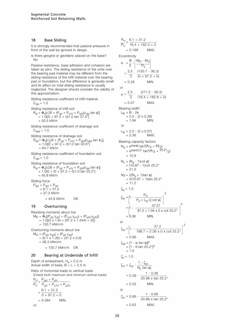
Segmental ConcreteReinforced Soil Retaining Walls
38
18 Base SlidingIt is strongly recommended that passive pressure in front of the wall be ignored in design.
Is there geogrid or geofabric placed on the base? No
Passive resistance, base adhesion and cohesion are taken as zero. The sliding resistance of the units over the bearing pad material may be different from the sliding resistance of the infill material over the bearing pad or foundation, but the difference is generally small and its effect on total sliding resistance is usually neglected. The designer should consider the validity of this approximation.
Sliding resistance coefficient of infill material Cdsi = 1.0
Sliding resistance of infill soil Rsi = Φn[c*i B + (PqV + Ps1V + Ps2V)cdsi tan φ*i] = 1.0[(0 + 97.2 + 0)1.0 tan 27.5°] = 50.5 kN/m
Sliding resistance coefficient of drainage soil Cdsd = 1.0
Sliding resistance of drainage soil Rsd = Φn[c*d B + (PqV + Ps1V + Ps2V)cdsd tan φ*d] = 1.0[(0 + 97.2 + 0)1.0 tan 33.6°] = 64.7 kN/m
Sliding resistance coefficient of foundation soil Cdsf = 1.0
Sliding resistance of foundation soil Rsf = Φn[c*f B + (PqV + Ps1V + Ps2V)cdsf tan φ*f] = 1.0[0 + (0 + 97.2 + 0)1.0 tan 25.2°] = 45.8 kN/m
Sliding force PaH = PqH + PsH = 6.1 + 31.2 = 37.3 kN/m
< 45.8 kN/m OK
19 OverturningResisting moments about toe MR = Φn[(PqV yqV) + (Ps1V ys1V) + (Ps2V ys2V)] = 1.0[(0 x 1.6) + (97.2 x 1.344) + (0)] = 130.7 kNm/m
Overturning moments about toe MO = (PqH yqH) + (PsH ysH) = (6.1 x 1.35) + (31.2 x 0.9) = 36.3 kNm/m
< 130.7 kNm/m OK
20 Bearing at Underside of InfillDepth of embedment, He = 0.3 m Actual width of base, B = L = 2.5 m
Ratio of horizontal loads to vertical loads (Check both maximum and minimum vertical loads)
PH =
PqH + PsH
PV PqV + Ps1V + Ps2V
= 6.1 + 31.2
0 + 97.2 + 0
= 0.384 MIN. or
PH =
6.1 + 31.2
PV 16.4 + 182.3 + 0
= 0.188 MAX.
Eccentricity
e = B
- MR - MO
2 PV
= 2.5 - (130.7 - 36.3)
2 (0 + 97.2 + 0)
= 0.28 MIN.
or
e = 2.5 - (271.2 - 36.3)
2 (16.4 + 182.8 + 0)
= 0.07 MAX.
Bearing width LB = B - 2e = 2.5 - (2 x 0.28) = 1.94 MIN.
or
LB = 2.5 - (2 x 0.07) = 2.36 MAX.
Bearing capacity factors Nq = eπ tanφ*f tan2(π/4 + φ*f/2) = eπ tan25.2° tan2(π/4 + 25.2°/2) = 10.9
Nc = (Nq - 1)cot φ*f = (10.87 - 1)cot 25.2° = 21.0
Nγ = 2(Nq + 1)tan φ*f = 2(10.87 + 1)tan 25.2° = 11.2
ζq = 1.0
ζqi = 1 -
PH 2
PV + LB c*f cot φ*f = 1 -
37.27 2
97.2 + 1.94 x 0 x cot 25.2°
= 0.38 MIN.
or
ζqi = 1 - 37.2 2
198.7 + 2.36 x 0 x cot 25.2°
= 0.66 MAX.
ζqt = [1 - α tan φ*f]2 = [1 - 0 tan 25.2°]2 = 1.0
ζc = 1.0
ζci = ζqi -
1 - ζqi
Nc tan φ*f = 0.38 -
1 - 0.38
20.98 x tan 25.2°
= 0.32 MIN.
or
ζci = 0.66 - 1 - 0.66
20.98 x tan 25.2°
= 0.62 MAX.
38

Segmental ConcreteReinforced Soil Retaining Walls
39
ζct = ζqt -
1 - ζqt
Nc tan φ*f = 1.0 -
1 - 1
21 x tan 25.2°
= 1.0
ζγ = 1.0
ζγi = 1 -
PH 3
PV + LB c*f cot φ*f = 1 -
37.2 3
97.2 + 1.94 x 0 x cot 25.2°
= 0.23 MIN.
or
ζγi = 1 - 37.2 3
198.7 + 2.36 x 0 x cot 25.2°
= 0.54 MAX.
ζγt = [1 - α tan φ*f]2
= [1 - 0 tan 25.2°]2
= 1.0
Average bearing strength capacity PVcap = Φn LB[(c*f Nc ζc ζci ζct) + (γ*f He Nq ζq ζqi ζqt) + (0.5 γ*f B Nγ ζγ ζγi ζγt)] = 167 kN/m MIN.
or
= 435 kN/m MAX.
Applied vertical force PV = PqV + Ps1V + Ps2V = 0 + 97.2 + 0 = 97.2 kN/m < 167 kN/m OK
or
PV = 16.4 + 182.3 + 0 = 198.7 kN/m < 435 kN/m OK
21 Internal StabilityActive pressure coefficient at infill soil
Kai = cos2(φ*i + ω)
cos2(ω)cos(ω - d*i) 1 + sin(φ*i + d*i)sin(φ*i - β) 2
cos(ω - d*i)cos(ω + β)
= cos2(27.5° + 4°) cos2(4°)cos(4° - 18.3°)
1 + sin(27.5° + 18.3°)sin(27.5° - 0°) 2
cos(4° - 18.3°)cos(4° + 0°)
= 0.30
22 Horizontal ForcesHorizontal active force due to surcharge PqHi = Kai[(Gdo qd) + (Glo ql)](H - Hu) cos (d*i - ω) = 0.3[(1.5 x 0) + (1.5 x 5.0)] (2.7 - 0.2) cos (18.3° - 4°) = 5.5 kN/m
Horizontal active force due to soil PsHi = Kai 0.5 Gdo γ*i (H - Hu)2 cos (d*i - ω) = 0.3 x 0.5 x 1.5 x 18 x (2.7 - 0.2)2 cos (18.3° - 4°) = 24.5 kN/m
Total horizontal force PHi = PqHi + PsHi = 5.5 + 24.5 = 30 kN/m
Minimum number of geogrid layers
Nmin = PHi
T*d
= 30 5.8 (Using TT060)
= 5.2
∴ Minimum possible number of geogrids is 6
23 Tensile StrengthGeogrid No. 1:
Elevation of geogrid E(1) = 0.2 m
Geogrid contributory area
Ac(1) = E(2) - E(1) + E(1)
2
= 0.6 - 0.2 + 0.2 2
= 0.4 m
Depth to midpoint of contributory area
D(1) = H - Ac(1)
2
= 2.7 - 0.2
2 = 2.5 m
Geogrid No. 2:
Elevation of geogrid E(2) = 0.8 m
Geogrid contributory area
Ac(2) = E(3) - E(2) +
E(2) - E(1)
2 2
= 1.0 - 0.6 + 0.6 - 0.2
2 2
= 0.4 m
Depth to midpoint of contributory area
D(2) = D(1) - Ac(1)
- Ac(2)
2 2
= 2.5 - 0.4
- 0.4
2 2 = 2.1 m
Similar for remaining geogrids
39
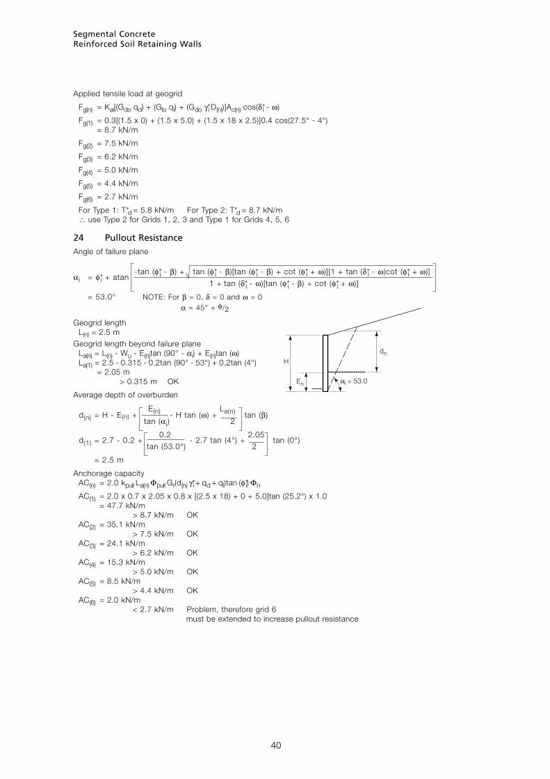
Segmental ConcreteReinforced Soil Retaining Walls
4040
Applied tensile load at geogrid
Fg(n) = Kai[(Gdo qd) + (Glo ql) + (Gdo γ*i D(n))]Ac(n) cos(d*i - ω)
Fg(1) = 0.3[(1.5 x 0) + (1.5 x 5.0) + (1.5 x 18 x 2.5)]0.4 cos(27.5° - 4°) = 8.7 kN/m
Fg(2) = 7.5 kN/m
Fg(3) = 6.2 kN/m
Fg(4) = 5.0 kN/m
Fg(5) = 4.4 kN/m
Fg(6) = 2.7 kN/m
For Type 1: T*d = 5.8 kN/m For Type 2: T*d = 8.7 kN/m ∴ use Type 2 for Grids 1, 2, 3 and Type 1 for Grids 4, 5, 6
24 Pullout ResistanceAngle of failure plane
αi = φ*i + atan -tan (φ*i - β) + tan (φ*i - β)[tan (φ*i - β) + cot (φ*i + ω)][1 + tan (d*i - ω)cot (φ*i + ω)]
1 + tan (d*i - ω)[tan (φ*i - β) + cot (φ*i + ω)]
= 53.0° NOTE: For β = 0, d = 0 and ω = 0 α = 45° + φ/2
Geogrid length L(n) = 2.5 mGeogrid length beyond failure plane La(n) = L(n) - Wu - E(n)tan (90° - αi) + E(n)tan (ω) La(1) = 2.5 - 0.315 - 0.2tan (90° - 53°) + 0.2tan (4°) = 2.05 m > 0.315 m OK
Average depth of overburden
d(n) = H - E(n) +
E(n) - H tan (ω) + La(n) tan (β)
tan (αi) 2
d(1) = 2.7 - 0.2 +
0.2 - 2.7 tan (4°) + 2.05
tan (0°) tan (53.0°) 2 = 2.5 m
Anchorage capacity AC(n) = 2.0 kpull La(n) Φpull Gr(d(n) γ*i + qd + ql)tan (φ*i) Φn
AC(1) = 2.0 x 0.7 x 2.05 x 0.8 x [(2.5 x 18) + 0 + 5.0]tan (25.2°) x 1.0 = 47.7 kN/m > 8.7 kN/m OK AC(2) = 35.1 kN/m > 7.5 kN/m OK AC(3) = 24.1 kN/m > 6.2 kN/m OK AC(4) = 15.3 kN/m > 5.0 kN/m OK AC(5) = 8.5 kN/m > 4.4 kN/m OK AC(6) = 2.0 kN/m < 2.7 kN/m Problem, therefore grid 6 must be extended to increase pullout resistance
H
En
dn

Segmental ConcreteReinforced Soil Retaining Walls
41
25 Internal Sliding ResistanceCheck sliding at lowest geogrid
Angle of failure plane
= 50.1°
Ineffective length of geogrid
∆L = E(n + 1) - E(n)
tan αr
= 0.6 - 0.2 tan 50.1°
= 0.334 m
Effective length of geogrid L’s(n) = L - Wu - ∆L = 2.5 - 0.315 - 0.334 = 1.85 m
Length of slope increment above wall
L’’s(n) = L’s(n) tan β tan ω
1 - tan β tan ω
= 1.85 tan 0° tan 4°
1 - tan 0° tan 4° = 0.0 m
Length of soil acting above top of wall Lβ(n) = L’s(n) + L’’s(n) = 1.85 + 0.0 = 1.85 m
Height of soil acting above top of wall h(n) = Lβ(n) tan β = 1.85 tan0° = 0.0 m
Weight of soil below top of wall acting on lowest geogrid W’r(n) = Gdr γ*i L’s(n) (H - E(n)) = 0.8 x 18 x 1.85(2.7 - 0.2) = 66.6 kN/m
Weight of soil above top of wall acting on lowest geogrid
W’rβ(n) = Gdr γ*i Lβ(n) L’s(n) tan β
2
= 0.8 x 18 x 1.85 x 1.85 tan 0° 2 = 0 kN/m
Surcharge force acting on lowest geogrid Q’rβ(n) = (Gdr qd + Glrql)Lβ(n) = [(0.8 x 0) + (0 x 5.0)]1.85 = 0 kN/m
Weight of wall acting on lowest unit/geogrid interface Ww(1) = Gv(H - E(1)) γ*sv Wu = 1.0(2.7 - 0.2)19.7 x 0.315 = 15.5 kN/m
Shear resistance of lowest unit/geogrid interface Vv(1) = [au + ( Ww(1) tan λv)] Φu slide Φn = [7.0 + (15.5 tan 23.5°)]0.8 x 1.0 = 10.9 kN/m
Total resistance RT(n) = Rs(n) + Vv(n) = 48.7 + 10.9 = 59.6 kN/m
Horizontal active force at lowest geogrid due to surcharge PqH(n) = Kar[(Gdo qd) + (Glo ql)](H - E(n) + h(n)) cos (d*i - ω) = 0.32[(1.5 x 0) + (1.5 x 5.0)] (2.7 - 0.2 + 0) cos (18.3° - 4°) = 5.6 kN/m
Horizontal active force at lowest geogrid due to soil PsH(n) = Kar 0.5 Gdo γ*r (H - E(n) + h(n))2 cos (d*r - ω) = 0.32 x 0.5 x 1.5 x 19 x (2.7 - 0.2 + 0)2 cos (25.2° - 4°) = 26.8 kN/m
Total horizontal active force at lowest geogrid PaH(n) = PqH(n) + PsH(n) = 5.6 + 26.8 = 32.5 kN/m < 59.6 kN/m OK
41
H
hn
E1
αr = φ*r + atan -tan (φ*r - β) + tan (φ*r - β)[tan (φ*r - β) + cot (φ*r + ω)][1 + tan (φ*r - ω)cot (φ*r + ω)]
1 + tan (φ*r - ω)[tan (φ*r - β) + cot (φ*r + ω)]
Sliding resistance at lowest geogrid R’s(n) = Φu slide kslide(W’r(n) + W’rβ(n) + Q’rβ(n))Lβ(n) tan (φ*i) Φn = 0.8 x 0.95(66.6 + 0 + 0)1.85 tan 27.5° x 1.0 = 48.7 kN/m

Segmental ConcreteReinforced Soil Retaining Walls
42
26 Connection StrengthGrid at bottom
Weight of wall acting on each geogrid connection Ww(n) = Gv(H(n) - E(n))γ*sv Wu
Ww(1) = 1.0(2.7 - 0.2)19.7 x 0.315 = 15.6 kN/m
Connection strength Tult con(n) = [acs + ( Ww(n) tan λcs)] Φu con Φn
Tult con(1) = [9 + (15.6 tan 30.8°)]0.75 x 1.0 = 13.7 kN/m
Force in connection
Pcon = H - E(n) 0.25 + 0.75 Fg(n)
H
= 2.7 - 0.2 0.25 + 0.75 8.7
2.7
= 8.5 kN/m < 13.7 kN/m OK
27 BulgingNOTE: Spacing limited to 600 which should account for bulging
Active pressure coefficient at infill soil Kai = 0.30
Horizontal active force due to surcharge PqHi(n) = Kai[(Gdo qd) + (Glo ql)](H - E(n)) cos (d*i - ω) = 0.30[(1.5 x 0) + (1.5 x 5.0)] (2.7 - 0.2) cos (18.3° - 4°) = 5.5 kN/m
Horizontal active force due to soil PsHi(n) = Kai 0.5 Gdo γ*i (H - E(n))2 cos (d*i - ω) = 0.30 x 0.5 x 1.5 x 18 x (2.7 - 0.2)2 cos (18.3° - 4°) = 24.5 kN/m
Total horizontal force PH(n) = PqHi(n) + PsHi(n) = 5.5 + 24.5 = 30.0
Net horizontal force at geogrid (see Item 23) PH(n) = PH(0) - Σ(Fg(n+1) to (n)) PH(1) = 30 - (7.5 + 6.2 + 5.0 + 4.4 + 2.7) = 4.2 kN/m
Unit/geogrid interface shear capacity (see Item 25) Vu(1) = 13.5 kN/m > 4.2 kN/m OK
42

Segmental ConcreteReinforced Soil Retaining Walls
43
APPENDIX D Typical Specification
Construction Specification
Australian StandardsAll components and installation shall comply with AS 4678 and the standards referred to therein.
Safety and Protection of Existing StructuresAll excavations shall be carried out in a safe manner in accordance with the relevant regulations, to prevent collapse that may endanger life or property.
In the absence regulations to the contrary, the following may be applied, where:■ the height of the wall does not exceed 3.2 m,■ excavation is performed and remains open only in
dry weather,■ there is no significant groundwater seepage,■ the excavation remains open for no longer than two
weeks,■ the back slope of the natural ground does not
exceed 1 vertical in 6 horizontal, ■ bedding planes do not slope towards the cut, and ■ there are no structures founded within a zone of
influence defined by a line from the toe of the cut at 30 degrees for cohesionless material and 45 degrees for other material.
Maximum Maximum permissible height of cut unpropped batterNatural material (m) Vert : horiz
Stable rock, sandstone, firm 0 – 3.2 1 : 0.4 shale etc where bedding planes do not slope towards Over 3.2 Seek advice of the excavation engineer
Materials with both 0 – 2.6 1 : 0.8 significant cohesion and friction in its undisturbed Over 2.6 Seek advice of natural compacted state engineer
Cohesive soils, 0 – 2.0 1 : 1.2 eg clay, silts Over 2.0 Seek advice of engineer
Cohesionless soils, 0 – 1.4 1 : 1.6 eg Loose gravel, sand Over 1.4 Seek advice of engineer
In all other cases, the advice of the Engineer shall be sought.
Adjacent structures must be founded either beyond or below the zone of influence. Where there is risk of global slip around a slip plane encompassing the proposed retaining wall or other structures, or where there is risk of inundation by ground water or surface water, retaining wall construction shall not proceed until remedial action has been carried out.
Foundation Material
If foundation material is of a type, grading or compaction that differs from that which is shown on the drawings, it shall be removed and replaced with a material that does comply.
Drainage System The drainage system shall consist of:■ A permeable wall facing system. ■ A permeable drainage layer not less than
300 mm wide adjacent to the stem of the wall. ■ A 100-mm slotted PVC agricultural pipe, or
equivalent system, draining to the storm-water system.
■ Additional drainage layers and/or geotextiles as specified on the drawings.
Drainage PipeThe drainage pipe shall be a 100-mm diameter slotted PVC agricultural pipe.
Drainage FillDrainage fill material shall be a nominal 10–20 mm GP (poorly-graded gravel) complying with the following specified grading:
Sieve Percent Passing
26.5 mm 100
19.00 mm 70–100
13.20 mm 0–100
9.52 mm 0
Geosynthetic Filter FabricGeosynthetic filter fabrics shall be of a material which:■ is not hydrophobic■ permits water to pass freely■ does not permit fine material to enter the drainage
layer■ has sufficient strength to resist tearing during the
placing and back-filling operations■ has the following specified properties.
For use behind retaining walls which are retaining silt, fine sand or similar materials:■ Minimum grab tensile strength to AS 2001.2.3, 600
N■ Minimum wide-strip tensile strength to AS 3706.2,
8.0 kN/m■ Minimum trapezoidal tear test to AS 3706.3,
200 N■ Minimum CBR burst strength to AS 3706.4,
1600 N■ Maximum pore size O95 by dry sieving to
AS 3706.7, 200 µm (woven fabric) ■ Minimum permittivity to AS 3706.9, 1.3 sec-1
■ Minimum coefficient of permeability to AS 3706.9, 0.003 m/sec
■ Minimum flow rate under 100 mm head to AS 3706.9, 220 l/m2/sec
43

Segmental ConcreteReinforced Soil Retaining Walls
44
Bulk Fill MaterialBulk fill material shall be uniform and of the type shown on the drawings. The maximum particle size is 100 mm. It is permissible to replace material of a lower design type with properly-compacted material of a higher design category.
Surface Sealing MaterialThe material used to seal the surface of the fill shall be compacted clay.
Concrete Facing BlocksUnless specified otherwise, concrete facing blocks shall comply with AS 4455 and the following requirements:■ Dimensional category DW4■ General purpose salt attack resistance grade■ Minimum characteristic compressive strength of 10
MPa■ To a colour and texture agreed in writing before the
supply takes place.
Broken or chipped units shall not be used. When it is necessary to cut units, they shall be cut with a saw rather than broken.
Infill MaterialInfill material shall be GW (well-graded gravel) or SW (well-graded sand) complying with the following specification.■ The pH of the back filling material shall be, for
polyester reinforcement, 4—9■ Plasticity Index shall not exceed 12%.■ Liquid Limit shall not exceed 30%.■ Coefficient of uniformity = D60/D10 shall exceed
5, where D6o and D10 are the equivalent sizes, in millimetres, as interpolated from the particle size distribution curve through which 60% and 10% of the material passes, respectively.
GeogridsThe geogrids shall be of the type and index strength nominated on the drawings.
Geogrids shall be a single length in the direction of design tension, not lapped, making provision for connection to the facing across the whole width of the facing and providing for the specified anchorage within the designated anchorage zone. Geogrids shall cover the whole of the plan area behind the wall for the specified anchorage length and shall be lapped with adjacent sections in accordance with the manufacturer’s instructions.
AdhesiveThe adhesive used to bond the capping units shall be a flexible two-part epoxy-based adhesive.
Preparation of Foundation MaterialWhere there are significant variations of foundation material or compaction, soft spots or where there is ponding of ground water, the material shall be removed, replaced and compacted in layers not exceeding 150 mm at a moisture content within
2% of Optimum Moisture Content (OMC) to achieve 95% Standard Proctor density.
Trenches and footing excavations shall be dewatered and cleaned prior to placement of drainage material or footings such that no softened or loosened material remains. If necessary place and compact foundation material in layers not exceeding 150 mm to make up levels. The levels beneath the wall shall not be made up with bedding sand or other poorly-graded granular material that may permit ground water to permeate under the base of the retaining wall, except where drainage material is specified and an adequate drainage system is designed.
Installing the Drainage SystemThe drainage pipe shall be positioned in the drainage fill at a minimum uniform grade of 1 in 100 over a length not exceeding 15 m. It shall be connected to the storm-water system at the lower end of each run and shall drain positively away from base of the retaining wall. The drainage pipe shall be brought to the surface at the upper end of each run to facilitate future flushing, capped and its positioned marked.
Installing Drainage FillCompact the drainage fill:■ around the drainage pipe to a minimum width of
300 mm behind the levelling fill■ behind the wall to a minimum width of 300 mm
behind the wall to within 150 mm of the top
Compaction shall be by mechanical plate vibrator to a minimum of 95% of the standard proctor density. All drainage fill must be adequately drained by the drainage system.
Installing Concrete Facing Units, Infill Material and GeogridsConcrete facing blocks shall be installed on the levelling pad or footing such that the resulting wall has a backward slope as specified on the drawings, but not less than 1 in 40. The units of successive courses shall be stacked in stretcher bond. In high walls that are curved in plan, it may be necessary to compensate for joint creep in the upper courses (the longitudinal translation of joints along the wall and the radius of curvature increases or decreases).
Geogrids shall be installed under tension applied by a system of stakes that shall remain in place until the geogrids are covered by at least 150 mm of infill material.
Infill material shall be placed, spread and compacted in a manner that eliminates wrinkles in the geogrid or movement of the facing units. Infill material shall be placed and compacted in layers equal to the height of the facing units, but not exceeding 200 mm in thickness, at a moisture content within 2% of Optimum Moisture Content (OMC) to achieve 95% Standard Proctor density. Infill material within 1.0 metre of the rear face of the retaining wall facing units shall be placed and compacted by at least three passes of a lightweight mechanical plate, tamper or roller at a moisture content within 2% of Optimum Moisture Content (OMC) to achieve 90% Standard Proctor density.
Tracked construction equipment shall not be operated
44

Segmental ConcreteReinforced Soil Retaining Walls
45
directly on the geogrids, which shall have a minimum of 150 mm of soil cover. In order to avoid disruption of the geogrids, tracked construction equipment shall not be turned on the infill material. Rubber tyred equipment may be used on the geogrids provided it is operated in accordance with the geogrid manufacturer’s instructions, without sudden braking and turning and at speed under 6 kilometres per hour.
At the end of each day’s construction, the infill material shall be sloped such that any rainwater is directed away from the face of the retaining wall and to a temporary (or permanent) drainage system.
The top facing unit or capping unit shall be bonded to the facing units below using an adhesive.
Unless specified otherwise for reasons of aesthetics or by the client or architect, all construction shall be within the following tolerances:
Installing Bulk Fill MaterialUnless required otherwise to support external loads, bulk filling material shall be placed and compacted behind the drainage material in layers not exceeding 200 mm at a moisture content within 2% of Optimum Moisture Content (OMC) to achieve 85% Standard Proctor density.
Installation of Surface Sealing Material and Catch DrainThe whole of the disturbed fill surface shall be sealed and drained by compacting a layer of surface-sealing material at least 150 mm thick and incorporating a 100-mm deep catch drain which drains to the site drainage system at a minimum slope of 1 in 100.
45
Vertical Horizontal Vertical Horizontal Element Position Position Alignment Alignment
Soil surface ± 100 mm - - -
Facings & wall structures ± 50 mm ± 50 mm ± 20 mm in 3.0 m ± 20 mm in 3.0 m
Footings & supports ± 50 mm ± 50 mm ± 20 mm in 3.0 m ± 20 mm in 3.0 m

TOP Access Bridge, Penrith Lakes, NSW
ABOVE Progress Road, Brisbane
LEFT LPG Cavern for Elgas, Sydney