Embed Size (px)
Citation preview

G U I D A N C E F O R A P P L I C A N T S
S T O R M W A T E R Q U A L I T Y M A N U A L F O R D E V E L O P M E N T P R O J E C T S I N M A R I N C O U N T Y
A Low Impact Development Approach
Prepared by the Marin County Stormwater Pollution Prevention Program (MCSTOPPP)
in cooperation with Marin County and Marin’s cities and towns

Version 6 February 2008
Marin County Stormwater Pollution Prevention Program (MCSTOPPP) P.O. Box 4186 Civic Center Plaza San Rafael, CA 94915-1560
M C S T O P P P
III
MCSTOPPP AGENCY STAFF COMMITTEE NEW DEVELOPMENT WORK GROUP
Jill Barnes
City of Mill Valley
Paul Bickner
City of Novato
Howard Bunce
MCSTOPPP
Bernice Davidson
County of Marin
Terri Fashing
MCSTOPPP
Marla Lafer
Regional Water Board
David Harlan
City of Novato
Alec Hoffman
County of Marin
Eric Steger
County of Marin
Steve Zeiger
City of San Rafael
MCSTOPPP CITIZENS ADVISORY COMMITTEE NEW DEVELOPMENT SUBCOMMITTEE
Aaron Stessman Kristine Pillsbury
ASSISTANCE FROM:
Dan Cloak Environmental Consulting www.dancloak.com

GUIDANCE FOR APPLICANTS: STORMWATER QUALITY MANUAL V
P R E F A C E
Twenty years ago, Congress amended the Clean Water Act to mandate controls on discharges from municipal separate storm sewer systems (MS4s). Acting under the Federal mandate and the California Water Code, California Water Boards require cities, towns, and counties to regulate activities which can result in pollutants entering their storm drains.
The Marin County Stormwater Pollution Prevention Program (MCSTOPPP) assists Marin County and its 11 cities and towns to meet these requirements. All Marin municipalities prohibit non-stormwater discharges to storm drains and require residents and businesses to use Best Management Practices (BMPs) to minimize the amount of pollutants in runoff. To enforce prohibitions and to promote the use of BMPs, the municipalities inspect businesses and construction sites, conduct public education and outreach, sweep streets, and clean storm drains. In addition, MCSTOPPP actively supports projects to assess, monitor, and restore local creeks and wetlands.
Since 1994, MCSTOPPP has promoted site design techniques—along with stormwater treatment facilities—that minimize pollutants in runoff during the entire life of a new development. The techniques are described and illustrated in the Bay Area Stormwater Management Agencies Association’s handbook, Start at the Source: Design Guidance Manual for Stormwater Quality Protection. Over the past dozen years, many Marin development projects have reduced impervious area, substituted pervious pavements for conventional asphalt or concrete and installed swales or bioretention facilities to retain and treat runoff.
Requirements for new developments were tightened in 2003. Marin municipalities must now comply with specific requirements and standards in a National Pollutant Discharge Elimination System (NPDES) permit covering small MS4s throughout California (Phase II permit). The requirements are being phased in through 2008.
MCSTOPPP created this guidance manual to assist applicants for development approvals to prepare submittals that demonstrate their project complies with the NPDES permit requirements. Projects in Novato, San Rafael, and unincorporated areas must implement the design standards in Attachment 4 to the permit and may follow this guidance to do so. Other municipalities may require project applicants to follow this guidance as part of their required program to implement new development controls.
Links
Marin County Stormwater Pollution Prevention Program (MCSTOPPP) www.mcstoppp.org
Bay Area Stormwater Management Agencies Association (BASMAA) www.basmaa.org
San Francisco Bay Regional Water Quality Control Board www.waterboards.ca.gov/sanfranciscobay
State Water Resources Control Board Phase II Stormwater Permit http://www.waterboards.ca.gov/stormwtr/phase_ii_municipal.html

GUIDANCE FOR APPLICANTS: STORMWATER QUALITY MANUAL VII
C O N T E N T S
Chapter 1. About the Stormwater Requirements
1-1 What Projects Must Comply
1-2 What is Low Impact Development?
Chapter 2. The Path to Stormwater Compliance
2-1 Step 1: Pre-Application Meeting
2-2 Step 2: Follow the Guidance
2-2 Step 3: Stormwater Control Plan
2-2 Step 4: Draft Bioretention Facilities Operation and Maintenance Plan
2-2 Step 5: Detailed Project Design
2-3 Step 6: Construct the Project
2-3 Step 7: Transfer Maintenance Responsibility
Chapter 3. Preparing Your Stormwater Control Plan
3-1 Objectives
3-1 Step 1: Opportunities and Constraints
3-2 Step 2: Conceptual Site Design
3-5 Step 3: Calculations and Documentation
3-5 Step 4: Bioretention Design Criteria
3-5 Step 5: Source Controls
3-6 Step 6: Bioretention Facility Maintenance
3-7 Step 7: Construction Checklist
Chapter 4. Documenting Your LID Design
4-1 NPDES Compliance and Low Impact Development
4-2 Step-by-Step
1. Delineate Drainage Management Areas
VIII GUIDANCE FOR APPLICANTS: STORMWATER QUALITY MANUAL
2. List DMAs by type and note runoff factors
3. Select and Lay Out Bioretention Facilities
4. Calculate minimum facility footprints
5. Repeat until facility area is adequate
Chapter 5. Preparing Your Bioretention Facilities Operation and Maintenance Plan
5-1 Introduction
5-2 Step-by-Step
1. Designate Responsible Individuals
2. Describe the Facilities to be Maintained
3. Select and Lay Out Bioretention Facilities
4. Calculate minimum facility footprints
5. Repeat until facility area is adequate
Tables and Checklists
1-1 Table 1-1: Requirements at a Glance
3-2 Stormwater Control Plan Checklist
3-7 Stormwater Construction Checklist
3-5 Table 3-1: Format for Tabulating Potential Pollutant Sources and Source Controls
4-3 Table 4-1: Runoff Factors for Small Storms
4-3 Table 4-2: Format for Tabulating Self-Treating Areas
4-3 Table 4-3: Format for Tabulating Self-Retaining Areas
4-3 Table 4-4: Format for Tabulating Areas Draining to Self-Retaining Areas
4-4 Table 4-5: Format for Tabulating Areas Draining to Bioretention Facilities and calculating minimum Bioretention Facility Size
Design Criteria
4-5 Bioretention swale or free-form area
4-6 Bioretention Planter
C H A P T E R
GUIDANCE FOR APPLICANTS: STORMWATER QUALITY MANUAL 1-1
A B O U T T H E S T O R M W A T E R R E Q U I R E M E N T S
Marin County and its 11 cities and towns are listed in a statewide Phase II municipal stormwater NPDES permit. The State Water Resources Control Board issued the permit in 2003. The permit requires all municipalities to address stormwater runoff from new development and redevelopment projects.
This Guidance for Applicants includes the applicable standards and requirements for submittals and may be used for projects in all Marin County jurisdictions.
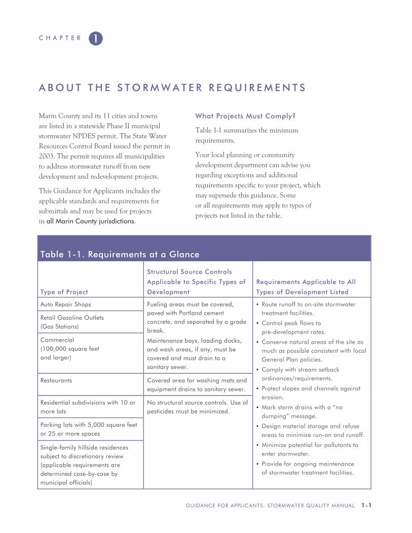
What Projects Must Comply?
Table 1-1 summarizes the minimum requirements.
Your local planning or community development department can advise you regarding exceptions and additional requirements specific to your project, which may supersede this guidance. Some or all requirements may apply to types of projects not listed in the table.
Table 1-1. Requirements at a Glance
Type of Project
Structural Source Controls
Applicable to Specific Types of
Development
Requirements Applicable to All
Types of Development Listed
Auto Repair Shops Fueling areas must be covered, paved with Portland cement concrete, and separated by a grade break.
Maintenance bays, loading docks, and wash areas, if any, must be covered and must drain to a sanitary sewer.
• Route runoff to on-site stormwater treatment facilities.
• Control peak flows to pre-development rates.
• Conserve natural areas of the site as much as possible consistent with local General Plan policies.
• Comply with stream setback ordinances/requirements.
• Protect slopes and channels against erosion.
• Mark storm drains with a “no dumping” message.
• Design material storage and refuse areas to minimize run-on and runoff.
• Minimize potential for pollutants to enter stormwater.
• Provide for ongoing maintenance of stormwater treatment facilities.
Retail Gasoline Outlets (Gas Stations)
Commercial (100,000 square feet and larger)
Restaurants Covered area for washing mats and equipment drains to sanitary sewer.
Residential subdivisions with 10 or more lots
No structural source controls. Use of pesticides must be minimized.
Parking lots with 5,000 square feet or 25 or more spaces
Single-family hillside residences subject to discretionary review (applicable requirements are determined case-by-case by municipal officials)
A B O U T T H E S T O R M W A T E R R E Q U I R E M E N T S
1–2 GUIDANCE FOR APPLICANTS: STORMWATER QUALITY MANUAL
Specific structural source controls, which aim to reduce pollutants from outdoor activities, are required for restaurants, auto repair shops, gas stations, and commercial developments 100,000 square feet and larger.
These types of development, as well as parking lots with 5,000 square feet or 25 or more spaces and subdivisions with 10 or more lots, must either disperse and infiltrate runoff or provide facilities to treat runoff prior to discharge. In addition, peak flows must be controlled to pre-development rates.
The requirements apply to redeveloped sites when 5,000 square feet or more of impervious area is created or replaced. If the impervious area is being increased by less than 50%, then the requirements apply only to the addition.
All projects must also conserve natural areas as much as possible consistent with General Plan requirements, protect slopes and channels against erosion, and comply with local stream setback policies.
What is Low Impact Development?
Marin municipalities have adopted a Low Impact Development (LID) approach to compliance with the requirements.
LID design aims to mimic pre-project site hydrology as well as protect water quality. Runoff from roofs and impervious paved areas is dispersed to landscaped areas or routed to planter boxes and other bioretention facilities distributed throughout the site. When native soils are clayey, these facilities may feature underdrains to convey treated stormwater to storm drains.
Some of the advantages of LID are:
• Provides effective stormwater treatment by filtering pollutants and sequestering them within soils.
• Processes pollutants through biological action in the soil, rendering some pollutants less toxic.
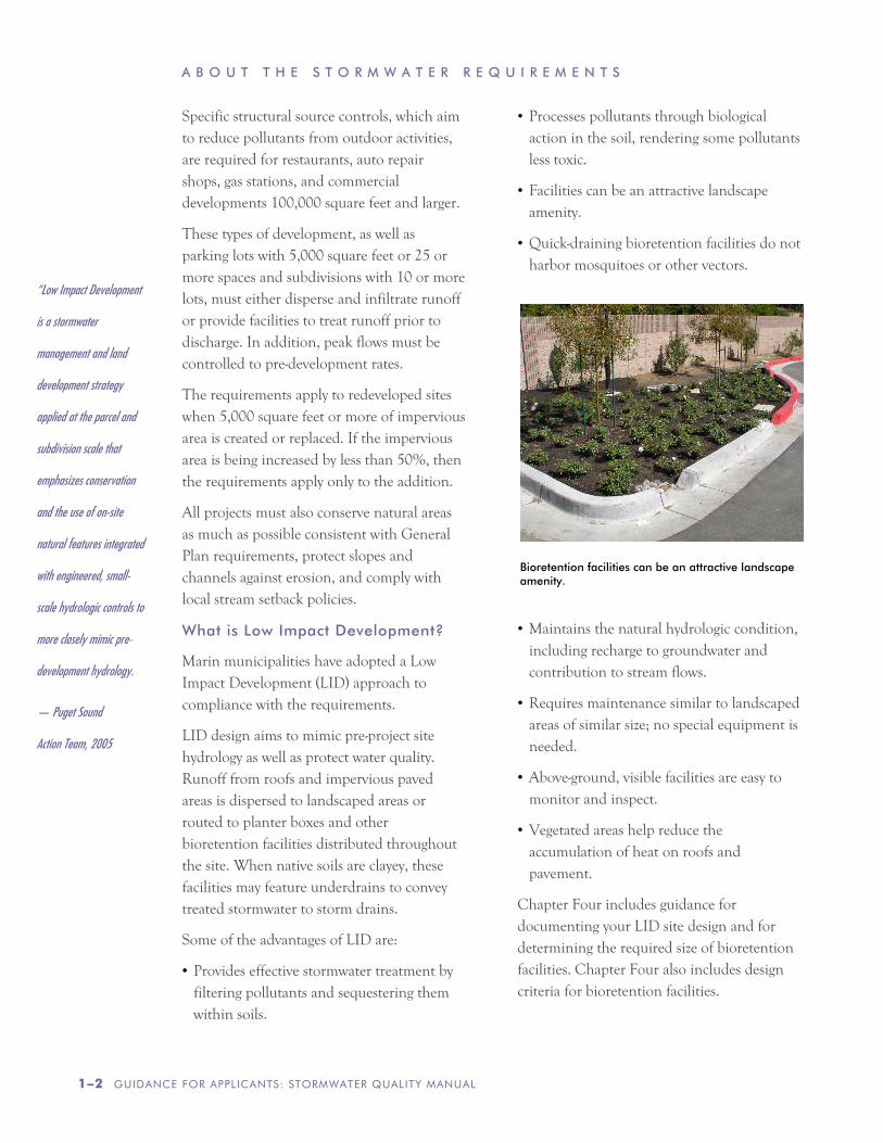
• Facilities can be an attractive landscape amenity.
• Quick-draining bioretention facilities do not harbor mosquitoes or other vectors.
• Maintains the natural hydrologic condition, including recharge to groundwater and contribution to stream flows.
• Requires maintenance similar to landscaped areas of similar size; no special equipment is needed.
• Above-ground, visible facilities are easy to monitor and inspect.
• Vegetated areas help reduce the accumulation of heat on roofs and pavement.
Chapter Four includes guidance for documenting your LID site design and for determining the required size of bioretention facilities. Chapter Four also includes design criteria for bioretention facilities.
Bioretention facilities can be an attractive landscape amenity.
“Low Impact Development
is a stormwater
management and land
development strategy
applied at the parcel and
subdivision scale that
emphasizes conservation
and the use of on-site
natural features integrated
with engineered, small-
scale hydrologic controls to
more closely mimic pre-
development hydrology.
— Puget Sound
Action Team, 2005
C H A P T E R
GUIDANCE FOR APPLICANTS: STORMWATER QUALITY MANUAL 2–1
T H E P A T H T O S T O R M W A T E R C O M P L I A N C E
Start Early
Stormwater facilities must be integrated into the planning, design, construction, operation, and maintenance of your development project.
Your strategy for stormwater compliance should be an integral part of the earliest decisions about how the site will be developed. Once subdivision lot lines have been sketched, or buildings and parking have been arranged on a commercial site, the stormwater compliance design may already be constrained—often unnecessarily.
At this earliest stage, also consider who will be responsible for maintaining stormwater treatment and flow-control facilities in perpetuity. The NPDES permit requires the local municipality to verify stormwater treatment facilities are being maintained and are operating as designed. The municipality will typically enter into a formal agreement with the property owner. The agreement will typically include provisions to allow access for inspections, require the property owner to retain an approved inspector and/or pay a fee to cover the cost of the inspections, and give the municipality the right to conduct remedial maintenance and recover costs in the event facilities are not properly maintained.
In residential subdivisions, the need to provide for maintenance of stormwater treatment facilities can affect the layout of
streets and lots, decisions whether to incorporate a homeowner’s association (HOA), liability, insurance, and capital considerations, and the value of the individual built lots. In addition, municipalities may require the builder provide an extended maintenance and warranty period for the facilities before turning them over to an HOA or other entity for maintenance in perpetuity. Again, it’s best to start early!
Here are some of the key stormwater compliance milestones as you manage your development project:
1: Pre-application meeting
2: Follow this Guidance
3: Stormwater Control Plan
4: Draft Stormwater Facilities Operation
and Maintenance Plan
5: Detailed Project Design
6: Construction
7: Transfer Maintenance Responsibility
1: Pre-Application Meeting
Discuss stormwater requirements for your project at a pre-application meeting with planning and community development staff. Their experience with similar projects and with local procedures, requirements, and community preferences can provide
“Plan and design your
stormwater controls
integrally with the site and
landscaping for your
project.”
A B O U T T H E S T O R M W A T E R R E Q U I R E M E N T S
2–2 GUIDANCE FOR APPLICANTS: STORMWATER QUALITY MANUAL
invaluable insights. Current contacts are listed at www.mcstoppp.org.
You might also discuss with staff the right timing for completing your Stormwater Control Plan. Often, site designs take a few iterative reviews (by staff or by a Design Review Committee) before a satisfactory site layout is achieved. It is important to consider site drainage and locations for bioretention facilities throughout this iterative process. However, it may make sense to delay compilation and formal submittal of the Stormwater Control Plan until the site layout is fairly well set.
2: Follow the Guidance
Read this guidance through and understand the principles and design procedures before beginning to design your project. Then, follow the steps in Chapter 3 as you lay out the site.
3: Stormwater Control Plan
Prepare a complete Stormwater Control Plan for submittal with your application for planning and zoning approval. The Stormwater Control Plan will demonstrate adequate stormwater treatment and flow-control measures can be accommodated within your site and landscape design.
Be sure the bioretention areas and other treatment and flow-control facilities shown on your Stormwater Control Plan Exhibit are also shown, as appropriate, on your preliminary site design, architectural design, and landscape designs.
Your Stormwater Control Plan may also be used in supporting a Negative Declaration or may be referenced in an Environmental Impact Report. In general, for most projects, implementing the techniques and criteria in this guidance will be considered to mitigate
the project’s potential impacts on stormwater quality.
If your project receives planning and zoning approval (entitlements), a Condition of Approval will specify the project be designed and constructed consistent with the Stormwater Control Plan.
As described in Chapter 3, your Stormwater Control Plan will include a Construction Checklist of items to be followed up during the final design phase of your project.
Your Stormwater Control Plan must also include a statement accepting responsibility to maintain the stormwater treatment facilities until that responsibility is transferred to the project operator or owner or another responsible party.
4: Draft Stormwater Facilities Operation and Maintenance Plan
The Stormwater Facilities Operation and Maintenance Plan (O&M Plan) is a living document used to plan, direct, and record maintenance of stormwater treatment facilities. It identifies the individuals responsible for maintenance, who must keep an up-to-date copy and file periodic updates with the municipality.
The final O&M plan should include as-built documentation of how the facilities are constructed. However, a draft plan, with appropriate placeholders, must be submitted at the time grading and building permits are processed. Single-family residences may be exempted on a case-by-case basis; check with municipal staff.
5: Detailed project design
During this stage, the landscape design must integrate the functionality of bioretention areas, planter boxes, and other stormwater
M C S T O P P P
GUIDANCE FOR APPLICANTS: STORMWATER QUALITY MANUAL 2-3
features into the aesthetic and functional values of the project.
Typical design issues include edges and transitions to allow runoff to flow from sidewalks and paved areas into bioretention areas, dissipation of energy gained by runoff flowing down slopes, planting and irrigation of bioretention facilities, and integration of berms, fences, and walls in or near bioretention facilities.
Chapter 4 includes design suggestions and tips.
The submitted construction documents should include the Construction Checklist cross-referencing the Stormwater Control Plan features with the plan sheets showing how the features have been executed.
6: Construct the Project
Careful construction of bioretention facilities, coordinated with the building of the development, will help ensure the facilities function as intended and will also minimize future maintenance problems. Items to check during construction include:
• Avoid compaction of native soils around where bioretention facilities will be constructed.
• Closely follow design elevations.
• Grade parking lots, driveways, and streets to promote evenly distributed sheet flow into bioretention facilities.
• Set overflow inlets at the proper height so the surface of the bioretention facility floods as intended.
7: Transfer Maintenance Responsibility
Following construction—or perhaps following a maintenance and warranty period—formally
transfer maintenance responsibility to the owner or operator of the project, who will maintain the facilities in perpetuity. In the case of a residential subdivision, this may be a homeowners association, if that arrangement has been approved by your municipality.
“Grade parking lots,
driveways and streets to
promote evenly distributed
sheet flow into bioretention
facilities.”

C H A P T E R
GUIDANCE FOR APPLICANTS: STORMWATER QUALITY MANUAL 3–1
P R E P A R I N G A S T O R M W A T E R C O N T R O L P L A N
Objectives
Your Stormwater Control Plan must demonstrate your project incorporates site design characteristics, landscape features, and engineered facilities that will, to the maximum extent practicable:
• Minimize imperviousness.
• Retain or detain stormwater.
• Slow runoff rates.
• Reduce pollutants in post-development runoff.
In particular, you will need to show all runoff from impervious areas is either dispersed to landscape or routed to a properly designed treatment facility.
A complete and thorough Stormwater Control Plan will enable municipal development review staff to verify your project complies with these requirements. It is strongly recommended you retain a design professional familiar with the requirements.
Contents
Your Stormwater Control Plan will consist of a report and an exhibit. Municipal staff will use the Stormwater Control Plan Checklist (page 3-2) to evaluate the completeness of your Plan.
Step by Step
Plan and design your stormwater controls integrally with the site plan and landscaping for your project. This strategy requires you
invest in early and ongoing coordination among project architects, landscape architects, and civil engineers. However, it can pay big dividends in a cost-effective, aesthetically pleasing design—and by avoiding design conflicts later.
Your initial, conceptual design for the project should include site drainage. This should include identifying areas where runoff can be dispersed and/or the location and approximate size of stormwater treatment and flow-control facilities.
Follow these seven steps to complete your preliminary design and your Stormwater Control Plan.
Step 1: Opportunities and Constraints
Step 2: Conceptual Site Design
Step 3: Calculations and Documentation
Step 4: Design Details
Step 5: Source Controls
Step 6: Maintenance
Step 7: Construction Checklist
A template containing an example outline can be downloaded from www.mcstoppp.org. When available, example Stormwater Control Plans will be posted there as well.
“Plan and design your
stormwater controls
integrally with the site and
landscaping for your
project.”
P R E P A R I N G A S T O R M W A T E R C O N T R O L P L A N
3–2 GUIDANCE FOR APPLICANTS: STORMWATER QUALITY MANUAL
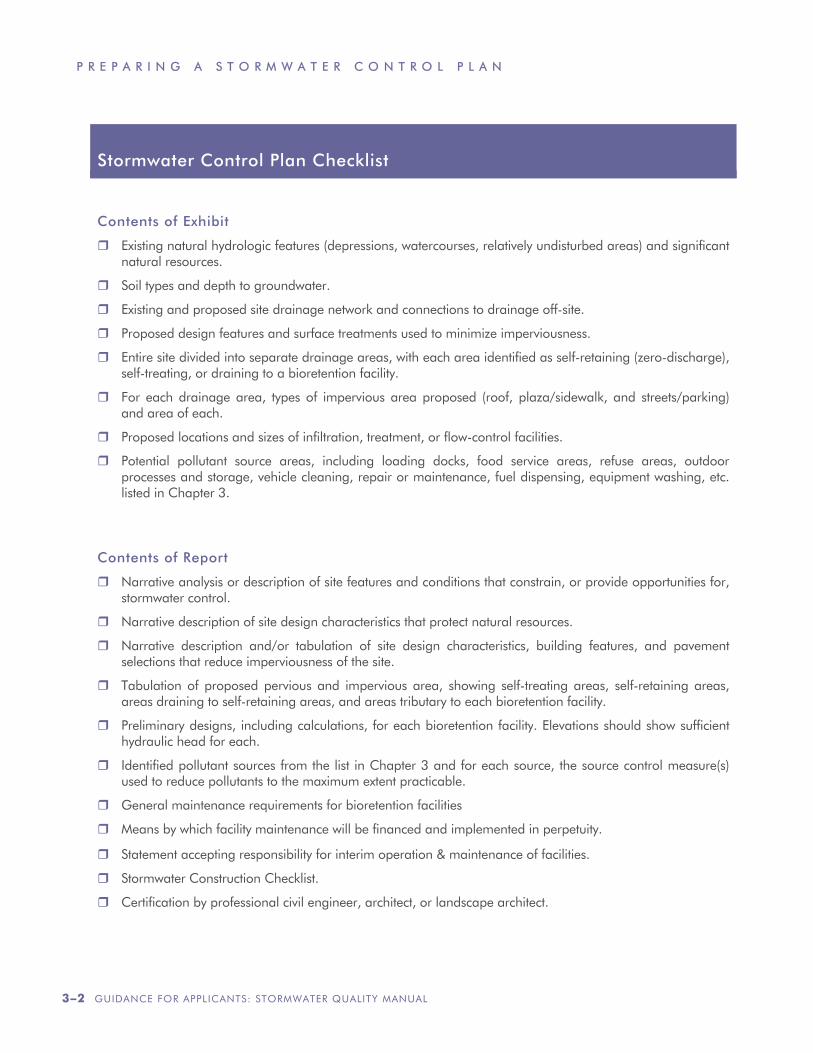
Stormwater Control Plan Checklist
Contents of Exhibit
Existing natural hydrologic features (depressions, watercourses, relatively undisturbed areas) and significant natural resources.
Soil types and depth to groundwater.
Existing and proposed site drainage network and connections to drainage off-site.
Proposed design features and surface treatments used to minimize imperviousness.
Entire site divided into separate drainage areas, with each area identified as self-retaining (zero-discharge), self-treating, or draining to a bioretention facility.
For each drainage area, types of impervious area proposed (roof, plaza/sidewalk, and streets/parking) and area of each.
Proposed locations and sizes of infiltration, treatment, or flow-control facilities.
Potential pollutant source areas, including loading docks, food service areas, refuse areas, outdoor processes and storage, vehicle cleaning, repair or maintenance, fuel dispensing, equipment washing, etc. listed in Chapter 3.
Contents of Report
Narrative analysis or description of site features and conditions that constrain, or provide opportunities for, stormwater control.
Narrative description of site design characteristics that protect natural resources.
Narrative description and/or tabulation of site design characteristics, building features, and pavement selections that reduce imperviousness of the site.
Tabulation of proposed pervious and impervious area, showing self-treating areas, self-retaining areas, areas draining to self-retaining areas, and areas tributary to each bioretention facility.
Preliminary designs, including calculations, for each bioretention facility. Elevations should show sufficient hydraulic head for each.
Identified pollutant sources from the list in Chapter 3 and for each source, the source control measure(s) used to reduce pollutants to the maximum extent practicable.
General maintenance requirements for bioretention facilities
Means by which facility maintenance will be financed and implemented in perpetuity.
Statement accepting responsibility for interim operation & maintenance of facilities.
Stormwater Construction Checklist.
Certification by professional civil engineer, architect, or landscape architect.
M C S T O P P P
GUIDANCE FOR APPLICANTS: STORMWATER QUALITY MANUAL 3–3
1: Opportunities and Constraints
The following information will help you determine the best stormwater control design for your development site:
• Existing natural hydrologic features, including natural areas, wetlands, watercourses, seeps, springs, and areas with significant trees.
• Site topography and drainage, including the contours of slopes, the general direction of surface drainage, local high or low points or depressions, and any outcrops or other significant geologic features.
• Zoning, including setbacks and minimum landscaping requirements and open space.
• Soil types, including hydrologic soil groups, and depth to groundwater.
Prepare a brief narrative describing site opportunities and constraints. This may help establish the maximum extent practicable degree of stormwater control for your site.
Opportunities might include low areas, oddly configured or otherwise unbuildable areas, setbacks, easements, or buffers (which can double as locations for bioretention facilities) and differences in elevation (which can provide hydraulic head).
Constraints might include impermeable soils, high groundwater, groundwater pollution or contaminated soils, steep slopes, geotechnical instability, high-intensity land use, heavy pedestrian or vehicle traffic, or safety concerns.
2: Conceptual Site Design
Optimize the site layout. Apply the following design principles:
• Define the development envelope and protected areas, identifying areas that are
most suitable for development and areas that should be left undisturbed.
• Limit grading; preserve natural landforms and drainage patterns.
• Set back development from creeks, wetlands, and riparian habitats to the maximum degree possible and at minimum, as required by local ordinances.
• Preserve significant trees.
Limit paving and roofs. Where possible, design compact, taller structures, narrower and shorter streets and sidewalks, smaller parking lots (fewer stalls, smaller stalls, and more efficient lanes), and indoor or underground parking. Examine the site layout and circulation patterns and identify areas where landscaping or planter boxes can be substituted for pavement.
Use pervious pavements where possible.
Inventory paved areas and identify locations where permeable pavements, such as crushed aggregate, turf block, unit pavers, pervious concrete, or pervious asphalt can be substituted for impervious concrete or asphalt paving. Pervious pavements are most applicable where native soils are permeable. On site with clay soils, it may still be possible to use turf block for emergency access lanes and overflow parking or to use unit pavers or pervious pavement with a sufficiently deep and well-drained base course.
Direct drainage to landscaped areas.
There are two options for handling runoff from impervious areas:
• Disperse runoff to lawns or landscaping. Limit the ratio of impervious to pervious area to 2:1 maximum. Pervious areas must be relatively flat, and the surface should be graded to a slightly concave surface to create a “self-retaining” area. Sites in densely
P R E P A R I N G A S T O R M W A T E R C O N T R O L P L A N
3–4 GUIDANCE FOR APPLICANTS: STORMWATER QUALITY MANUAL
urbanized areas are often too constrained to implement this option.
• Route runoff to bioretention facilities. The bioretention areas should have a surface area of at least 4% of the tributary impervious area. Bioretention facilities may be configured as above-ground or in-ground planter boxes, in a linear fashion as swales, or in free-form fashion as “rain gardens” or bioretention areas.
See Chapter 4 for design information on self-retaining areas and bioretention facilities.
Tips for Conceptual Drainage Design.
In clay soils, bioretention facilities must be underdrained. A bioretention facility requires three to four feet of head from inlet to underdrain outlet, which can be connected to an underground storm drain or daylighted.
On flat sites, it usually works best to intersperse self-retaining areas and bioretention facilities throughout the site. Grade streets, parking lots, and driveways to sheet flow runoff directly into the landscaped areas. Use gutters, rather than underground pipes, to convey runoff longer distances.
On sloped sites, it may work better to collect upslope runoff in conventional catch basins and pipe it to downslope bioretention facilities.
Use the head from roof downspouts by connecting leaders all the way to landscaping or bioretention facilities. Where necessary, bubble-ups can be used to disperse piped runoff.
Siting bioretention facilities. Facilities should be publicly accessible for inspection and maintenance.
In commercial, mixed-use, and multi-family developments, facilities can be located in
parking medians, parking islands, street setbacks, side and rear setbacks, and other landscaped areas.
In residential subdivisions, the most practical strategy is to drain the lots to the street in the conventional manner, and then drain the street to a bioretention area. It may be most advantageous to create a separate parcel owned in common, which can double as a landscape amenity or a park. (This is one reason why it is important to plan stormwater treatment and flow-control before drawing subdivision lot lines.) If necessary, house roofs can be drained to planter boxes, and driveways drained to separate small bioretention areas. Keep in mind, however, that facilities in back or side yards should be avoided. If facilities are located on individual lots, prospective buyers may find undesirable the necessary legal restrictions on what they can do with those facilities.
Other types of treatment facilities. Bioretention facilities are generally suitable for Marin’s modestly sized developments, clay soils, and setback requirements. Bioretention facilities sized to a minimum 4% of tributary impervious area can typically be fit into parking medians, street setbacks, foundation plantings, and other landscaping features without significantly altering the uses of the site.
Further, bioretention facilities are relatively easy to maintain, provide aesthetic appeal, attenuate peak flows, and are quite effective at removing pollutants, including pollutants associated with very fine particulates in rain and atmospheric dust.
Bioretention facilities can usually be designed and located so that runoff to the inlet, and away from the underdrain, is by gravity. Where this cannot be achieved, the next-best
“On flat sites, it usually
works best to intersperse
self-retaining areas and
bioretention facilities
throughout the site.”
M C S T O P P P
GUIDANCE FOR APPLICANTS: STORMWATER QUALITY MANUAL 3–5
option is to capture runoff in a vault and pump it to a bioretention facility.
In some cases, it is very difficult to accommodate bioretention facilities on sites smaller than an acre and that have “zero-lot-line”–type zoning.
On these types of developments, the feasibility of the following treatment facilities should be considered, in order:
• Bioretention facilities fed and drained by gravity.
• Bioretention facilities with pumped inflow or discharge.
• Sand filters with a minimum surface area equal to 4% of tributary impervious area. Sand filters may be below ground, but the entire surface must be easily accessible for maintenance (e.g., covered with a removable grate).
• A higher-rate (smaller-surface-area) biofilter, such as a tree-pit-style unit. The grading and drainage design should minimize the area draining to each unit and maximize the number of discrete drainage areas and units.
• A higher-rate vault-based filtration unit.
3. Calculations and Documentation
Your Stormwater Control Plan must include an Exhibit showing the entire site divided into Drainage Management Areas and the
locations and approximate sizes of bioretetention facilities. Each should be clearly labeled so the Exhibit can be cross-referenced to the text and tables in the report.
The report will include a brief description of each Drainage Management Area and each bioretention facility—and tabulated calculations.
Chapter 4 includes a detailed procedure for documenting your design and showing your bioretention facilities meet the minimum sizing requirements.
4. Bioretention Design Criteria
Design criteria in Chapter Four will assist you to plan for construction of bioretention facilities as part of your project. The criteria that apply to your planned facilities should be summarized in your Stormwater Control Plan.
5. Source Controls
Your Stormwater Control Plan must state if any of the following potential pollutant sources will be created or expanded as part of the development project. If so, list the sources in the format shown in Table 3-1, and for each source, describe how the appropriate source controls will be built into the project.
Refuse. Dumpsters and other refuse-holding areas must be roofed and must be bermed to
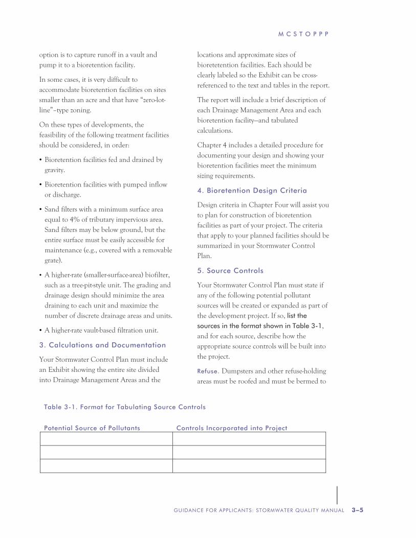
Table 3-1. Format for Tabulating Source Controls
Potential Source of Pollutants
Controls Incorporated into Project
P R E P A R I N G A S T O R M W A T E R C O N T R O L P L A N
3–6 GUIDANCE FOR APPLICANTS: STORMWATER QUALITY MANUAL
prevent runoff from flowing into or away from the area. The refuse area must be drained to the sanitary sewer, typically through a grease interceptor.
Maintenance and Storage. Materials must be covered. Storage of non-hazardous liquids must be covered by a roof, be contained by berms, dikes, liners, or vaults, and/or be drained to the sanitary sewer. Hazardous
materials must be stored in compliance with the local hazardous materials ordinance and a Hazardous Materials Management Plan for the site.
Food Service. Restaurants, grocery stores, and other food service operations must have a floor sink or similar facility for cleaning floor mats, containers, and equipment. The sink must be connected to the sanitary sewer via a grease interceptor.
Vehicle or Equipment Maintenance.
Accommodate all vehicle repair and maintenance indoors, or designate an
outdoor work area and design the area to prevent run-on and runoff of stormwater. Indoor vehicle repair areas should be designed without drains.
Vehicle and Equipment Cleaning.
Commercial car wash facilities must be designed so no runoff is discharged to the storm drains. A recirculating system may be used. Similarly, commercial and industrial facilities with vehicle cleaning needs must have a covered, bermed area for washing. Multi-family complexes may prohibit on-site car washing or have a paved, bermed, and covered car wash area.
Pools, spas, fountains, and ponds. Water features must have a sanitary sewer cleanout in an accessible area within 10 feet.
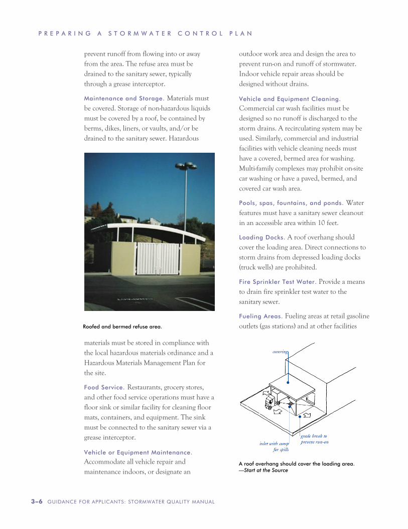
Loading Docks. A roof overhang should cover the loading area. Direct connections to storm drains from depressed loading docks (truck wells) are prohibited.
Fire Sprinkler Test Water. Provide a means to drain fire sprinkler test water to the sanitary sewer.
Fueling Areas. Fueling areas at retail gasoline outlets (gas stations) and at other facilities
A roof overhang should cover the loading area. —Start at the Source
Roofed and bermed refuse area.
M C S T O P P P
GUIDANCE FOR APPLICANTS: STORMWATER QUALITY MANUAL 3–7
must be covered with a canopy, paved with Portland cement concrete, and separated by a grade break. Downspouts from the canopy must be directed away from the fueling area.
6. Bioretention Facility Maintenance
In your Stormwater Control Plan, specify the means by which maintenance of your bioretention facilities will be financed and implemented in perpetuity.
For commercial, mixed-use or multifamily developments, maintenance responsibility may be assigned to a management entity that will be responsible for keeping up the buildings and grounds. Your Stormwater Facilities Operation and Maintenance Plan, to be submitted later, will need to specify how maintenance will be funded and budgeted. Typically, the entity assuming responsibility for maintenance will need to execute a Stormwater Management Facilities Agreement, which runs with the land and provides for periodic inspections and reporting at the facility owner’s expense.
For residential subdivisions, consult with municipal staff, then detail the planned arrangements in your Stormwater Control Plan. Include, as available and applicable, information about joint ownership of parcels where bioretention facilities are to be located, about incorporating a homeowners association, about provisions to be incorporated in Codes, Covenants, and Restrictions, and other relevant information.
For single-family residences not built as part of a larger plan of development, your municipality may waive the need for a maintenance agreement and Operation and Maintenance Plan.
Include in your Stormwater Control Plan the following statement:
“The applicant accepts responsibility for interim operation and maintenance of stormwater treatment and flow-control facilities until such time as this responsibility is formally transferred to a subsequent owner.”
A complete and detailed list of maintenance and inspection requirements, including inspection frequencies, will be required in your Stormwater Facilities Operation and Maintenance Plan (O&M Plan). Your O&M plan must also include detailed documentation of how your facilities are constructed.
For this stage, include in your Stormwater Control Plan a summary of the general maintenance requirements for your bioretention facilities. You will find example lists of maintenance requirements in Chapter 5.
7. Construction Checklist
Include in your Stormwater Control Plan a Construction Checklist following the format below.
Format for Stormwater Construction Checklist
Page Number
in Stormwater
Control Plan
Source Control or Treatment Control Measure
Plan
Sheet
#
P R E P A R I N G A S T O R M W A T E R C O N T R O L P L A N
3–8 GUIDANCE FOR APPLICANTS: STORMWATER QUALITY MANUAL
Complete the first two columns in the checklist, listing each stormwater source control and treatment measure identified in the plan and identifying the page number where it appears.
Later, cut-and-paste the same table into your construction documents. Complete the rightmost column, listing the sheet number(s) where the same measure is shown on the construction plans.
8. Certification
Include the following statement by a licensed civil engineer, architect, or landscape architect:
“The preliminary design of stormwater treatment facilities and other stormwater pollution control measures in this plan are in accordance with the current edition of the Marin County Stormwater Pollution Prevention Program’s Guidance for Applicants.”
C H A P T E R
GUIDANCE FOR APPLICANTS: STORMWATER QUALITY MANUAL 4–1
D O C U M E N T I N G Y O U R L I D D E S I G N
NPDES Compliance and LID
The following design and documentation procedure facilitates rapid and thorough evaluation of a LID design for compliance with the requirements in the NPDES permit.
The procedure involves dividing the site into Drainage Management Areas (DMAs), tracking the drainage from each DMA, and ensuring bioretention facilities receiving that drainage are adequately sized to treat the runoff.
As specified in the NPDES permit, bioretention facilities are designed to retain and treat runoff produced by a rainfall intensity of 0.2 inches per hour. Measured over years, these low-intensity storms produce most of the total volume of runoff (80% or more).
MCSTOPPP’s recommended designs for bioretention facilities include an imported planting medium that will filter runoff at a rate of at least 5 inches per hour.
If 100% of rainfall ends up as inflow to the bioretention facility (a conservative assumption), then the ratio of tributary impervious area to bioretention surface area needs to be:
0.2 inches/hour ÷ 5 inches/hour = 0.04
This ratio, or sizing factor, greatly simplifies calculations.
Step-by-Step
The procedure requires the following steps:
1. Delineate DMAs.
2. Identify DMA types and runoff factors.
3. Select and lay out bioretention facilities.
4. Calculate the minimum area (footprint) of each bioretention facility.
5. Repeat as necessary until the available area exceeds the minimum area for each bioretention facility.
1: Delineate DMAs
Drainage Management Areas (DMAs) are portions of a project site that drain to a common point. Each DMA must contain only one type of surface (e.g., either landscaped or impervious). There are four types of DMAs:
• Self-treating areas
• Self-retaining areas
• Areas draining to self-retaining areas
• Areas draining to a bioretention facility
Self treating areas are landscaped or turf areas which do not drain to bioretention facilities, but rather drain directly off site or to the storm drain system. Examples include upslope undeveloped areas which are ditched and drained around a development and grassed slopes which drain directly to a street or storm drain. In general, self-treating areas include no impervious areas, unless the impervious area is very small (5% or less) relative to the receiving pervious area and
D O C U M E N T I N G Y O U R L I D D E S I G N
4–2 GUIDANCE FOR APPLICANTS: STORMWATER QUALITY MANUAL
slopes are gentle enough to ensure runoff will be absorbed into the vegetation and soil.
Self-retaining areas are used where, because of site layout or topography, it is not possible to drain entirely pervious areas off-site separately. The technique works best on flat, heavily landscaped sites. To create self-retaining turf and landscape areas in flat areas or on terraced slopes, berm the area or depress the grade into a concave cross-section so that these areas will retain the first inch of rainfall. Specify slopes, if any, toward the center of the pervious areas. Inlets of area drains, if any, should be set 3 inches or more above the low point to allow ponding.
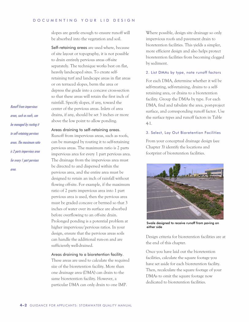
Areas draining to self-retaining areas. Runoff from impervious areas, such as roofs, can be managed by routing it to self-retaining pervious areas. The maximum ratio is 2 parts impervious area for every 1 part pervious area. The drainage from the impervious area must be directed to and dispersed within the pervious area, and the entire area must be designed to retain an inch of rainfall without flowing off-site. For example, if the maximum ratio of 2 parts impervious area into 1 part pervious area is used, then the pervious area must be graded concave or bermed so that 3 inches of water over its surface are absorbed before overflowing to an off-site drain. Prolonged ponding is a potential problem at higher impervious/pervious ratios. In your design, ensure that the pervious areas soils can handle the additional run-on and are sufficiently well-drained.
Areas draining to a bioretention facility. These areas are used to calculate the required size of the bioretention facility. More than one drainage area (DMA) can drain to the same bioretention facility. However, a particular DMA can only drain to one IMP.
Where possible, design site drainage so only impervious roofs and pavement drain to bioretention facilities. This yields a simpler, more efficient design and also helps protect bioretention facilities from becoming clogged by sediment.
2. List DMAs by type, note runoff factors
For each DMA, determine whether it wil be self-treating, self-retaining, drains to a self-retaining area, or drains to a bioretention facility. Group the DMAs by type. For each DMA, find and tabulate the area, post-project surface, and corresponding runoff factor. Use the surface types and runoff factors in Table 4-1.
3. Select, Lay Out Bioretention Facilities
From your conceptual drainage design (see Chapter 3) identify the locations and footprint of bioretention facilities.
Design criteria for bioretention facilities are at the end of this chapter.
Once you have laid out the bioretention facilities, calculate the square footage you have set aside for each bioretention facility. Then, recalculate the square footage of your DMAs to omit the square footage now dedicated to bioretention facilities.
Runoff from impervious
areas, such as roofs, can
be managed by routing it
to self-retaining pervious
areas. The maximum ratio
is 2 parts impervious area
for every 1 part pervious
area.
Swale designed to receive runoff from paving on either side
M C S T O P P P
GUIDANCE FOR APPLICANTS: STORMWATER QUALITY MANUAL 4–3
4. Calculate minimum facility footprints
The minimum area for each bioretention facility is found by summing up the contributions of each tributary DMA and multiplying by the sizing factor of 0.04.
Table 4-5 extends the tabulation of DMAs draining to bioretention facilities to a calculation of the required minimum area of the receiving bioretention facility. Complete Table 4-5 for each bioretention facility.
5. Repeat until facility area is adequate
After computing the minimum bioretention facility size using Steps 1–4, review the site plan to determine if the reserved space for the facility is sufficient. If so, the planned facilities will meet the NPDES permit sizing requirements. If not, revise your plan accordingly. Revisions may include:
• Reducing the overall imperviousness of the project site.
• Changing the grading and drainage to redirect some runoff toward other bioretention facilities which may have excess capacity.
• Making tributary landscaped DMAs self-treating or self-retaining.
• Expanding the bioretention facility surface area.
Bioretention facility design criteria
Bioretention facilities may be of any suitable configuration: as a bioretention area (free-form shape with sloping sides), as a swale (linear shape with sloping sides), as an in-ground planter (with vertical sides) or as an above-ground planter.
Planters should allow infiltration to native soils except where geotechnical concerns are paramount (e.g. on unstable slopes or within 10 feet of building foundations), in which case they may be sealed except for a piped underdrain to an approved discharge point.
D O C U M E N T I N G Y O U R L I D D E S I G N
4–4 GUIDANCE FOR APPLICANTS: STORMWATER QUALITY MANUAL
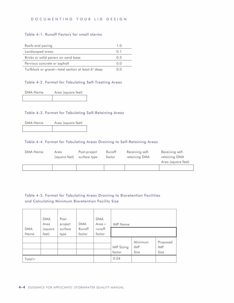
Table 4-1. Runoff Factors for small storms
Roofs and paving 1.0
Landscaped areas 0.1
Bricks or solid pavers on sand base 0.5
Pervious concrete or asphalt 0.0
Turfblock or gravel—total section at least 6" deep 0.0
Table 4-2. Format for Tabulating Self-Treating Areas DMA Name
Area (square feet)
Table 4-3. Format for Tabulating Self-Retaining Areas DMA Name
Area (square feet)
Table 4-4. Format for Tabulating Areas Draining to Self-Retaining Areas DMA Name
Area (square feet)
Post-project surface type
Runoff factor
Receiving self- retaining DMA
Receiving self- retaining DMA Area (square feet)
Table 4-5. Format for Tabulating Areas Draining to Bioretention Facilities
and Calculating Minimum Bioretention Facility Size
DMA Name
DMA Area (square feet)
Post-project surface type
DMA Runoff factor
DMA Area × runoff factor
IMP Name
IMP Sizing factor
Minimum IMP Size
Proposed IMP Size
Total> 0.04
M C S T O P P P
GUIDANCE FOR APPLICANTS: STORMWATER QUALITY MANUAL 4–5
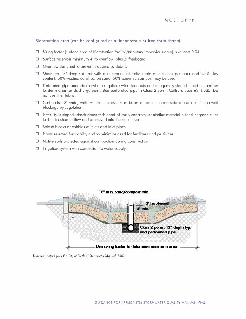
Drawing adapted from the City of Portland Stormwater Manual, 2002
Bioretention area (can be configured as a linear swale or free-form shape)
Sizing factor (surface area of bioretention facility)/(tributary impervious area) is at least 0.04.
Surface reservoir minimum 4" to overflow, plus 2" freeboard.
Overflow designed to prevent clogging by debris.
Minimum 18" deep soil mix with a minimum infiltration rate of 5 inches per hour and <5% clay content. 50% washed construction sand, 50% screened compost may be used.
Perforated pipe underdrain (where required) with cleanouts and adequately sloped piped connection to storm drain or discharge point. Bed perforated pipe in Class 2 perm, Caltrans spec 68-1.025. Do not use filter fabric.
Curb cuts 12" wide, with ½" drop across. Provide an apron on inside side of curb cut to prevent blockage by vegetation.
If facility is sloped, check dams fashioned of rock, concrete, or similar material extend perpendicular to the direction of flow and are keyed into the side slopes.
Splash blocks or cobbles at inlets and inlet pipes.
Plants selected for viability and to minimize need for fertilizers and pesticides.
Native soils protected against compaction during construction.
Irrigation system with connection to water supply.
D O C U M E N T I N G Y O U R L I D D E S I G N
4–6 GUIDANCE FOR APPLICANTS: STORMWATER QUALITY MANUAL
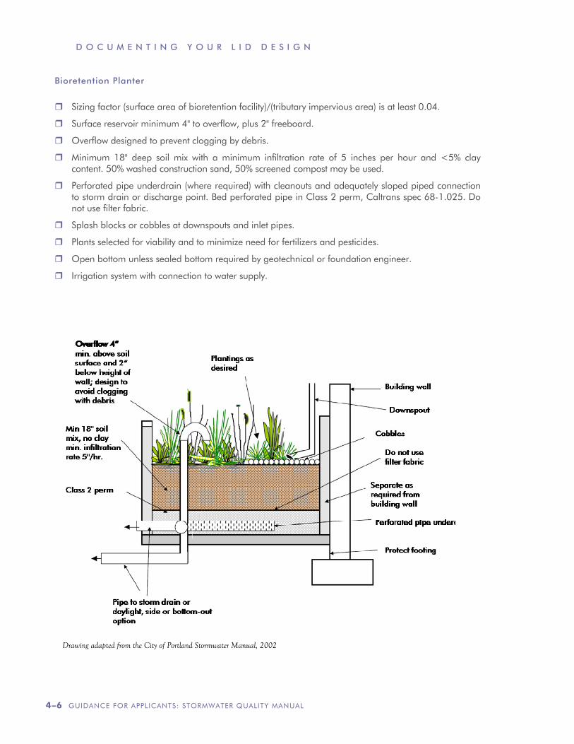
Bioretention Planter
Sizing factor (surface area of bioretention facility)/(tributary impervious area) is at least 0.04.
Surface reservoir minimum 4" to overflow, plus 2" freeboard.
Overflow designed to prevent clogging by debris.
Minimum 18" deep soil mix with a minimum infiltration rate of 5 inches per hour and <5% clay content. 50% washed construction sand, 50% screened compost may be used.
Perforated pipe underdrain (where required) with cleanouts and adequately sloped piped connection to storm drain or discharge point. Bed perforated pipe in Class 2 perm, Caltrans spec 68-1.025. Do not use filter fabric.
Splash blocks or cobbles at downspouts and inlet pipes.
Plants selected for viability and to minimize need for fertilizers and pesticides.
Open bottom unless sealed bottom required by geotechnical or foundation engineer.
Irrigation system with connection to water supply.
Drawing adapted from the City of Portland Stormwater Manual, 2002
C H A P T E R
GUIDANCE FOR APPLICANTS: STORMWATER QUALITY MANUAL 5–1
P R E P A R I N G Y O U R B I O R E T E N T I O N F A C I L I T I E S O P E R A T I O N & M A I N T E N A N C E P L A N
Introduction
Bioretention facilities require little care beyond normal maintenance and periodic rejuvenation of the landscaping.
However, as required by the statewide Phase II municipal NPDES stormwater permit, applicants must verify provisions have been made for maintenance of the facilities in perpetuity.
Typically this is accomplished by executing and recording an agreement that “runs with the land.” The agreement provides the municipality a right of access for inspections and requires the owner to conduct a maintenance inspection at least annually and retain a record of the inspection. If maintenance is not adequate, the municipality may conduct any maintenance or repairs needed and bill the owner to recover costs. The agreement is binding on future owners of the entire property or any subdivided portion of the property. A model agreement is at www.mcstoppp.org.
When bioretention facilities are located in a privately owned common area, such as street or landscaped area within a residential subdivision, the joint responsibilities of the property owners must be spelled out in codes, covenants, and restrictions (CC&Rs).
The Operation and Maintenance Plan (O&M Plan) is customized to address the specific
drainage patterns and treatment facilities on the development site and is typically referenced in the agreement or attached as an exhibit. The O&M Plan is used to plan, direct, and record maintenance of the bioretention facilities. The O&M Plan is kept on-site, and a copy maintained at municipal offices.
Updated information, including contact information, must be provided to the municipality whenever a property is sold and whenever designated individuals or contractors change.
Step by Step
Follow these five steps to prepare your bioretention facilities O&M Plan.
Step 1: Designate Responsible Individuals
Step 2: Describe the Facilities
Step 3: Document the Facilities “As Built”
Step 4: Schedule Maintenance Activities
Step 5: Compile the Plan
1. Designate Responsible Individuals.
Identify the following individuals:
• Person who will have direct responsibility for the maintenance of stormwater controls, maintain self-inspection records, and sign any correspondence with the municipality regarding the inspections.
O P E R A T I O N A N D M A I N T E N A N C E O F F A C I L I T I E S
5–2 GUIDANCE FOR APPLICANTS: STORMWATER QUALITY MANUAL
• Employees or contractors who will report to the designated contact and are responsible for carrying out maintenance.
• Contact for response to problems, such as clogged drains or broken irrigation mains, that would require immediate response should they occur during off-hours.
Describe the methods and schedule of initial training for staff or contractors regarding the purpose, mode of operation, and maintenance requirements for the facilities on the site.
2. Describe the Facilities to be Maintained
Incorporate the following into the O&M Plan:
• Figures from your Stormwater Control Plan delineating the Drainage Management Areas on the site and showing the locations of the bioretention facilities.
• The tabulation of the Drainage Management Areas from the calculations in your Stormwater Control Plan.
3. Document Facilities “As Built”
Include from the final construction drawings:
• Plans, elevations, and details of the bioretention facilities. If necessary, annotate the drawings with the designations used in the Stormwater Control Plan so it is clear which drawing refers to which facility.
• Construction details and specifications, including depths of sand or soil, compaction, pipe materials, and bedding.
• Location and layouts of inflow piping and piping to off-site discharge.
• Native soils encountered (e.g., sand or clay lenses beneath or near facilities).
Municipalities will typically require a draft Operations and Maintenance Plan be submitted when building permits are applied for — or even before.
Changes made in the field during construction should be noted in the final Plan following construction.
4. Schedule Maintenance Activities
The following should govern any routine landscape maintenance conducted on bioretention facilities:
• Maintain the design elevation of the soil or mulch surface, which should be a minimum 4 inches below the overflow elevation.
• Remove any soil or debris blocking planter inlets or overflows.
• Use only compost or other organic material to amend or condition soils. Amendments to planter soils must not reduce the infiltration rate.
• Do not fertilize unless plant health requires it. If fertilizer is required, use only slow-release organic fertilizers.
• Pesticides may be applied only by a licensed pest control operator trained in the use of Integrated Pest Management.
• Confirm that irrigation is adequate but not excessive. If underdrains flow during dry weather, reduce irrigation.
The following activities should be conducted routinely each month and following significant storms. The same activities should be conducted and recorded as part of the annual inspection.
• Check rocks at inlets and repair, replace, or replenish as necessary.
• Remove any accumulations of sediment, litter, and debris.
“Municipalities will
typically require a draft
Operations and
Maintenance Plan be
submitted when building
permits are applied for —
or even before.”
M C S T O P P P
GUIDANCE FOR APPLICANTS: STORMWATER QUALITY MANUAL 5–3
• Examine the overflow. Remove any debris. Note any damaged or disconnected piping.
• Check cleanouts and confirm underdrain piping is intact and unobstructed.
• Observe walls and other structural elements fix any holes, cracks, or failure.
• Check that the soil surface is level and is at least four inches below the overflow height.
• Note condition of vegetation and replace any dead plants.
• Prune or remove any overgrown plants or shrubs that may interfere with operation of the planter.
• Remove any nuisance or invasive vegetation.
• Clean up fallen leaves or debris and replenish mulch.
• Confirm that irrigation is adequate and not excessive.
5. Compiling the Plan
Format plans to 8½" x 11" where possible to facilitate duplication, filing, and handling. Include the revision date in the footer of each page.
Consider scanning the graphics and incorporating with the text in electronic files that can be backed up.
The following resources at www.mcstoppp.org may help you when preparing your plan:
• Sample outline and format for an O&M Plan.
• Form for designating individuals responsible for operation and maintenance.
• Sample facility inspection and maintenance log.
• Sample contents of an inspector’s report.
Updates to the O&M Plan
Updates can be made, and a copy transmitted to the municipality, at any time. In particular, contact information should be updated timely.
The O&M Plan should be updated as needed at the time of the annual inspection.