Embed Size (px)
Citation preview
J. KieferGuggenheim School of Aerospace Engineering,
Georgia Institute of Technology,
Atlanta, GA 30332-0150
M. WardGuggenheim School of Aerospace Engineering,
Georgia Institute of Technology,
Atlanta, GA 30332-0150
M. CostelloDavid S. Lewis Professor of Autonomy,
Guggenheim School of Aerospace Engineering,
Woodruff School of Mechanical Engineering,
Georgia Institute of Technology,
Atlanta, GA 30332-0150
e-mail: [email protected]
Rotorcraft Hard LandingMitigation Using RoboticLanding GearA unique, beneficial feature of rotorcraft is their flexibility in aircraft-to-ground interfac-ing. For a variety of reasons, hard landings can occur when the descent rate of the air-craft is larger than intended. The resulting impact can result in vehicle damage,structural failure, injuries, etc. To reduce these risks, an attractive solution is the imple-mentation of a robotic legged landing gear (RLLG) system. The system softens a hardlanding by acting as a shock absorber with a relatively large stroke, allowing the aircraftto decelerate over a much larger distance compared with a tradition landing gear system.This paper explores the mitigation of rotorcraft hard landings via RLLG through a com-prehensive multibody dynamics simulation tool. The purpose of this study is to demon-strate the efficacy of the RLLG as a robust solution to reduce loads during hard landingsfor multiple landing configurations. The results show that when using RLLG in place ofconventional landing gear, peak loads are reduced by approximately 70–90%, dependingon the landing conditions. Through Monte Carlo simulation, robotic landing gear systemperformance is shown to be robust to uncertain conditions. [DOI: 10.1115/1.4032286]
1 Introduction
Rotorcraft is an invaluable air vehicle for accessing remoteareas that are difficult or impossible to reach by other means. Aunique feature of rotorcraft is their inherent flexibility in aircraft-to-ground interfacing, including complex terrain. However, land-ing in uncertain conditions in stressful scenarios can lead to hardlandings. A hard landing involves controlled, but relatively rapiddescent of the aircraft before impacting the ground with relativelyhigh-speed. Hard landings vary in seriousness from causing mildpassenger discomfort to situations resulting in serious vehicledamage, structural failure, cargo damage, injuries, and possibleloss of life. When an aircraft experiences a hard landing, it mustbe inspected for damage before its next flight. Hard landings aredifferent from crash landings, which are characterized by uncon-trolled descent into the ground and usually result in destruction ofthe vehicle. A crash landing could be considered a more severecase of a hard landing. In both cases, it is desirable for the landinggear system to minimize the loads and acceleration experiencedby the aircraft.
Hard landings can occur due to several factors, including poorweather conditions, poor visibility, over-loaded aircraft,mechanical/electrical failures, and pilot error. Research has beenperformed to mitigate the effects of restricted visibility on thepilot’s ability to operate the aircraft [1–5]. Coltman, Bolukbasi,and Laananen examined the causes of over 1000 rotorcraft crasheswithin a 5-yr period [6]. It was found that rotorcraft crashes andhard landings involve injuries ranging from minor to fatal, withinjuries due to excessive accelerations being particularly hazard-ous. It has also been shown that spinal injuries are due mainly tothe vertical velocity changes during impact [7]. Due to the factthat rotorcraft generally has a higher accident rate than airliners[8], crash dynamics of rotorcraft have been the subject of a signifi-cant body of literature, which lends itself to the study of hardlandings. For example, several studies have found that the proba-bility of injury and/or damage to the aircraft can be decreasedthrough the design of hard landing mitigation technology [6–10].Potential solutions have included the redesign of aircraft seats,
subfloor, and landing gear. Conventional landing gear design isguided by Military Standard 1290 (a), which stipulates a set oflandings that the aircraft must be able to perform without substan-tial damage [11]. The landing gear and supporting components aresized to be sufficiently stout for these limiting hard landing cases.Additionally, conventional landing gear has been optimized forcrash landings [12–17]. The skids of conventional landing gearabsorb impact through plastic strain of the cross members. Assuch, the capability of the landing gear deteriorates over time[13]. There are also design tradeoffs when considering durability,strength, landing performance, cost, and weight. To improve ontraditional skid gear, several shock absorbing methods have beenconsidered. Some of these solutions include external, deployableairbags, collapsible honeycomb structures [18–20], collapsiblemetallic tubes [21], supplemental systems to be added to conven-tional landing gear, and other ideas [22–29]. Many of these solu-tions are difficult to implement, not reusable, add significantweight, and offer no additional benefits other than improved crashdynamics. An improved solution for reducing loads experiencedduring hard landings and crash landings is through the use ofRLLG. RLLG for rotorcraft has been considered for increasingslope landing performance and decreasing pilot workload duringlanding leading to the ability of rotorcraft to land on unpreparedlanding zones with complex terrain [30].
This paper explores mitigation of rotorcraft hard landing effectsby replacing conventional skid or wheel-based landing gear withan RLLG system. The mobility offered by robotic landing gearprovides a means for a highly effective shock absorber with a rela-tively large stroke during impact. It is shown that RLLG providesa powerful and robust means to reduce loads and acceleration onthe rotorcraft during hard landing events for a variety of landingconditions. Furthermore, numerous RLLG concepts are evaluatedto form a clear picture of how this type of landing gear can protectrotorcraft from hard landings.
This paper begins by detailing the models and methods used ina multibody dynamic simulation tool, including descriptions themultibody simulation method, contact model, and control algo-rithm. The dynamic behavior of typical hard landings is thendescribed in terms of an example rotorcraft for multiple landingconditions and landing gear configurations. Finally, the results ofparametric trade studies and Monte Carlo simulations are pre-sented, detailing the increased performance in hard landing miti-gation offered by the RLLG in multiple configurations.
Contributed by the Dynamic Systems Division of ASME for publication in theJOURNAL OF DYNAMIC SYSTEMS, MEASUREMENT, AND CONTROL. Manuscript receivedFebruary 2, 2015; final manuscript received December 3, 2015; published onlineJanuary 12, 2016. Assoc. Editor: Yongchun Fang.
Journal of Dynamic Systems, Measurement, and Control MARCH 2016, Vol. 138 / 031003-1Copyright VC 2016 by ASME
Downloaded From: http://dynamicsystems.asmedigitalcollection.asme.org/ on 03/28/2016 Terms of Use: http://www.asme.org/about-asme/terms-of-use
2 Hard Landing Event Simulation
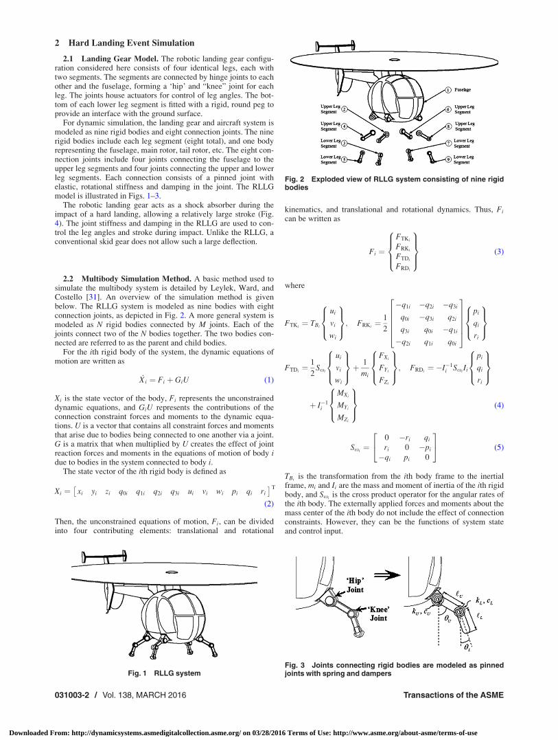
2.1 Landing Gear Model. The robotic landing gear configu-ration considered here consists of four identical legs, each withtwo segments. The segments are connected by hinge joints to eachother and the fuselage, forming a ‘hip’ and “knee” joint for eachleg. The joints house actuators for control of leg angles. The bot-tom of each lower leg segment is fitted with a rigid, round peg toprovide an interface with the ground surface.
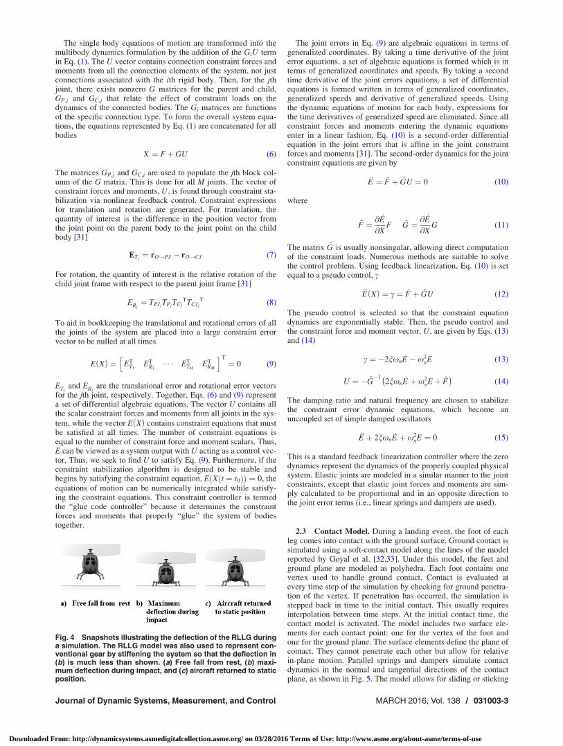
For dynamic simulation, the landing gear and aircraft system ismodeled as nine rigid bodies and eight connection joints. The ninerigid bodies include each leg segment (eight total), and one bodyrepresenting the fuselage, main rotor, tail rotor, etc. The eight con-nection joints include four joints connecting the fuselage to theupper leg segments and four joints connecting the upper and lowerleg segments. Each connection consists of a pinned joint withelastic, rotational stiffness and damping in the joint. The RLLGmodel is illustrated in Figs. 1–3.
The robotic landing gear acts as a shock absorber during theimpact of a hard landing, allowing a relatively large stroke (Fig.4). The joint stiffness and damping in the RLLG are used to con-trol the leg angles and stroke during impact. Unlike the RLLG, aconventional skid gear does not allow such a large deflection.
2.2 Multibody Simulation Method. A basic method used tosimulate the multibody system is detailed by Leylek, Ward, andCostello [31]. An overview of the simulation method is givenbelow. The RLLG system is modeled as nine bodies with eightconnection joints, as depicted in Fig. 2. A more general system ismodeled as N rigid bodies connected by M joints. Each of thejoints connect two of the N bodies together. The two bodies con-nected are referred to as the parent and child bodies.
For the ith rigid body of the system, the dynamic equations ofmotion are written as
_Xi ¼ Fi þ GiU (1)
Xi is the state vector of the body, Fi represents the unconstraineddynamic equations, and GiU represents the contributions of theconnection constraint forces and moments to the dynamic equa-tions. U is a vector that contains all constraint forces and momentsthat arise due to bodies being connected to one another via a joint.G is a matrix that when multiplied by U creates the effect of jointreaction forces and moments in the equations of motion of body idue to bodies in the system connected to body i.
The state vector of the ith rigid body is defined as
Xi ¼ xi yi zi q0i q1i q2i q3i ui vi wi pi qi ri
� �T
(2)
Then, the unconstrained equations of motion, Fi, can be dividedinto four contributing elements: translational and rotational
kinematics, and translational and rotational dynamics. Thus, Fi
can be written as
Fi ¼
FTKi
FRKi
FTDi
FRDi
8>><>>:
9>>=>>; (3)
where
FTKi¼ TBi
ui
vi
wi
8><>:
9>=>;; FRKi
¼ 1
2
�q1i �q2i �q3i
q0i �q3i q2i
q3i q0i �q1i
�q2i q1i q0i
266664
377775
pi
qi
ri
8><>:
9>=>;
FTDi¼ 1
2Sxi
ui
vi
wi
8><>:
9>=>;þ
1
mi
FXi
FYi
FZi
8><>:
9>=>;; FRDi
¼ �I�1i Sxi
Ii
pi
qi
ri
8><>:
9>=>;
þ I�1i
MXi
MYi
MZi
8><>:
9>=>; (4)
Sxi¼
0 �ri qi
ri 0 �pi
�qi pi 0
24
35 (5)
TBiis the transformation from the ith body frame to the inertial
frame, mi and Ii are the mass and moment of inertia of the ith rigidbody, and Sxi
is the cross product operator for the angular rates ofthe ith body. The externally applied forces and moments about themass center of the ith body do not include the effect of connectionconstraints. However, they can be the functions of system stateand control input.
Fig. 1 RLLG system
Fig. 2 Exploded view of RLLG system consisting of nine rigidbodies
Fig. 3 Joints connecting rigid bodies are modeled as pinnedjoints with spring and dampers
031003-2 / Vol. 138, MARCH 2016 Transactions of the ASME
Downloaded From: http://dynamicsystems.asmedigitalcollection.asme.org/ on 03/28/2016 Terms of Use: http://www.asme.org/about-asme/terms-of-use
The single body equations of motion are transformed into themultibody dynamics formulation by the addition of the GiU termin Eq. (1). The U vector contains connection constraint forces andmoments from all the connection elements of the system, not justconnections associated with the ith rigid body. Then, for the jthjoint, there exists nonzero G matrices for the parent and child,GP;j and GC;j that relate the effect of constraint loads on thedynamics of the connected bodies. The Gi matrices are functionsof the specific connection type. To form the overall system equa-tions, the equations represented by Eq. (1) are concatenated for allbodies
_X ¼ Fþ GU (6)
The matrices GP;j and GC;j are used to populate the jth block col-umn of the G matrix. This is done for all M joints. The vector ofconstraint forces and moments, U; is found through constraint sta-bilization via nonlinear feedback control. Constraint expressionsfor translation and rotation are generated. For translation, thequantity of interest is the difference in the position vector fromthe joint point on the parent body to the joint point on the childbody [31]
ETj¼ rO!PJ � rO!CJ (7)
For rotation, the quantity of interest is the relative rotation of thechild joint frame with respect to the parent joint frame [31]
ERj¼ TPJj
TPjTCj
TTCJj
T (8)
To aid in bookkeeping the translational and rotational errors of allthe joints of the system are placed into a large constraint errorvector to be nulled at all times
E Xð Þ ¼ ETT1
ETR1� � � ET
TMET
RM
h iT
¼ 0 (9)
ETjand ERj
are the translational error and rotational error vectorsfor the jth joint, respectively. Together, Eqs. (6) and (9) representa set of differential algebraic equations. The vector U contains allthe scalar constraint forces and moments from all joints in the sys-
tem, while the vector E Xð Þ contains constraint equations that mustbe satisfied at all times. The number of constraint equations isequal to the number of constraint force and moment scalars. Thus,E can be viewed as a system output with U acting as a control vec-tor. Thus, we seek to find U to satisfy Eq. (9). Furthermore, if theconstraint stabilization algorithm is designed to be stable andbegins by satisfying the constraint equation, E X t ¼ t0ð Þð Þ ¼ 0, theequations of motion can be numerically integrated while satisfy-ing the constraint equations. This constraint controller is termedthe “glue code controller” because it determines the constraintforces and moments that properly “glue” the system of bodiestogether.
The joint errors in Eq. (9) are algebraic equations in terms ofgeneralized coordinates. By taking a time derivative of the jointerror equations, a set of algebraic equations is formed which is interms of generalized coordinates and speeds. By taking a secondtime derivative of the joint errors equations, a set of differentialequations is formed written in terms of generalized coordinates,generalized speeds and derivative of generalized speeds. Usingthe dynamic equations of motion for each body, expressions forthe time derivatives of generalized speed are eliminated. Since allconstraint forces and moments entering the dynamic equationsenter in a linear fashion, Eq. (10) is a second-order differentialequation in the joint errors that is affine in the joint constraintforces and moments [31]. The second-order dynamics for the jointconstraint equations are given by
€E ¼ ~F þ ~GU ¼ 0 (10)
where
~F ¼ @_E
@XF ~G ¼ @
_E
@XG (11)
The matrix ~G is usually nonsingular, allowing direct computationof the constraint loads. Numerous methods are suitable to solvethe control problem. Using feedback linearization, Eq. (10) is setequal to a pseudo control, c
€E Xð Þ ¼ c ¼ ~F þ ~GU (12)
The pseudo control is selected so that the constraint equationdynamics are exponentially stable. Then, the pseudo control andthe constraint force and moment vector, U, are given by Eqs. (13)and (14)
c ¼ �2nxn_E � x2
nE (13)
U ¼ � ~G�1
2nxn_E þ x2
nEþ ~F� �
(14)
The damping ratio and natural frequency are chosen to stabilizethe constraint error dynamic equations, which become anuncoupled set of simple damped oscillators
€E þ 2nxn_E þ x2
nE ¼ 0 (15)
This is a standard feedback linearization controller where the zerodynamics represent the dynamics of the properly coupled physicalsystem. Elastic joints are modeled in a similar manner to the jointconstraints, except that elastic joint forces and moments are sim-ply calculated to be proportional and in an opposite direction tothe joint error terms (i.e., linear springs and dampers are used).
2.3 Contact Model. During a landing event, the foot of eachleg comes into contact with the ground surface. Ground contact issimulated using a soft-contact model along the lines of the modelreported by Goyal et al. [32,33]. Under this model, the feet andground plane are modeled as polyhedra. Each foot contains onevertex used to handle ground contact. Contact is evaluated atevery time step of the simulation by checking for ground penetra-tion of the vertex. If penetration has occurred, the simulation isstepped back in time to the initial contact. This usually requiresinterpolation between time steps. At the initial contact time, thecontact model is activated. The model includes two surface ele-ments for each contact point: one for the vertex of the foot andone for the ground plane. The surface elements define the plane ofcontact. They cannot penetrate each other but allow for relativein-plane motion. Parallel springs and dampers simulate contactdynamics in the normal and tangential directions of the contactplane, as shown in Fig. 5. The model allows for sliding or sticking
Fig. 4 Snapshots illustrating the deflection of the RLLG duringa simulation. The RLLG model was also used to represent con-ventional gear by stiffening the system so that the deflection in(b) is much less than shown. (a) Free fall from rest, (b) maxi-mum deflection during impact, and (c) aircraft returned to staticposition.
Journal of Dynamic Systems, Measurement, and Control MARCH 2016, Vol. 138 / 031003-3
Downloaded From: http://dynamicsystems.asmedigitalcollection.asme.org/ on 03/28/2016 Terms of Use: http://www.asme.org/about-asme/terms-of-use
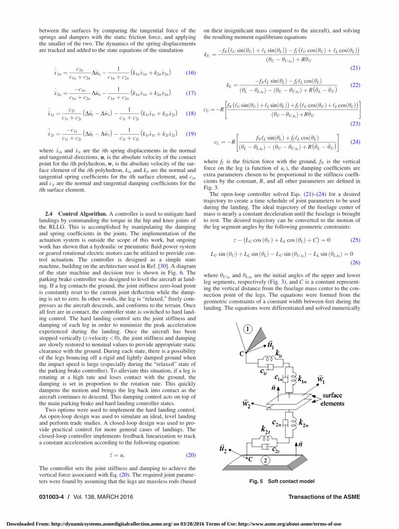
between the surfaces by comparing the tangential force of thesprings and dampers with the static friction force, and applyingthe smaller of the two. The dynamics of the spring displacementsare tracked and added to the state equations of the simulation
_s*
1n ¼c2n
c1n þ c2nDu
*
n �1
c1n þ c2nk1n s
*
1n þ k2n s*
2n
� �(16)
_s*
2n ¼�c1n
c1n þ c2nDu
*
n �1
c1n þ c2nk1n s
*
1n þ k2n s*
2n
� �(17)
_s*
1t ¼c2t
c1t þ c2tDu
*
t � Dw*
t
� �� 1
c1t þ c2tk1t s
*
1t þ k2t s*
2t
� �(18)
_s*
2t ¼�c1t
c1t þ c2tDu
*
t � Dw*
t
� �� 1
c1t þ c2tk1t s
*
1t þ k2t s*
2t
� �(19)
where s*
in and s*
it are the ith spring displacements in the normaland tangential directions, ui is the absolute velocity of the contactpoint for the ith polyhedron, wi is the absolute velocity of the sur-face element of the ith polyhedron, kin and kit are the normal andtangential spring coefficients for the ith surface element, and cin
and cit are the normal and tangential damping coefficients for theith surface element.
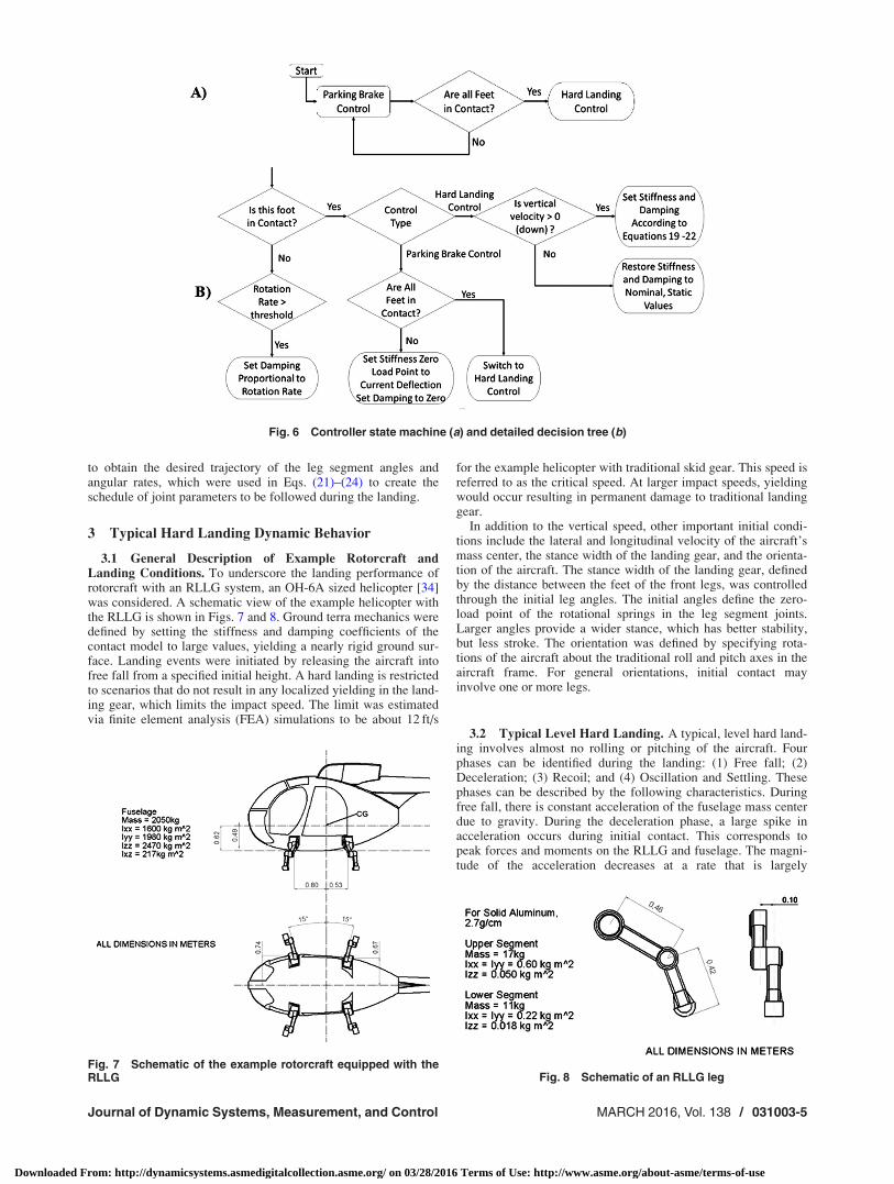
2.4 Control Algorithm. A controller is used to mitigate hardlandings by commanding the torque in the hip and knee joints ofthe RLLG. This is accomplished by manipulating the dampingand spring coefficients in the joints. The implementation of theactuation system is outside the scope of this work, but ongoingwork has shown that a hydraulic or pneumatic fluid power systemor geared rotational electric motors can be utilized to provide con-trol actuation. The controller is designed as a simple statemachine, building on the architecture used in Ref. [30]. A diagramof the state machine and decision tree is shown in Fig. 6. Theparking brake controller was designed to level the aircraft at land-ing. If a leg contacts the ground, the joint stiffness zero-load pointis constantly reset to the current joint deflection while the damp-ing is set to zero. In other words, the leg is “relaxed,” freely com-presses as the aircraft descends, and conforms to the terrain. Onceall feet are in contact, the controller state is switched to hard land-ing control. The hard landing control sets the joint stiffness anddamping of each leg in order to minimize the peak accelerationexperienced during the landing. Once the aircraft has beenstopped vertically (z-velocity< 0), the joint stiffness and dampingare slowly restored to nominal values to provide appropriate staticclearance with the ground. During each state, there is a possibilityof the legs bouncing off a rigid and lightly damped ground whenthe impact speed is large (especially during the “relaxed” state ofthe parking brake controller). To alleviate this situation, if a leg isrotating at a high rate and loses contact with the ground, thedamping is set in proportion to the rotation rate. This quicklydampens the motion and brings the leg back into contact as theaircraft continues to descend. This damping control acts on top ofthe main parking brake and hard landing controller states.
Two options were used to implement the hard landing control.An open-loop design was used to simulate an ideal, level landingand perform trade studies. A closed-loop design was used to pro-vide practical control for more general cases of landings. Theclosed-loop controller implements feedback linearization to tracka constant acceleration according to the following equation:
€z ¼ uc (20)
The controller sets the joint stiffness and damping to achieve thevertical force associated with Eq. (20). The required joint parame-ters were found by assuming that the legs are massless rods (based
on their insignificant mass compared to the aircraft), and solvingthe resulting moment equilibrium equations
kU ¼�fN ‘U sin hUð Þ þ ‘L sin hLð Þ
� �� ff ‘U cos hUð Þ þ ‘L cos hLð Þ
� �hU � hU;t0ð Þ þ R _hU
(21)
kL ¼�fN‘L sin hLð Þ � ff ‘L cos hLð Þ
hL � hL;t0ð Þ � hU � hU;t0ð Þ þ R _hL � _hU
� � (22)
cU¼�RfN ‘U sin hUð Þþ‘L sin hLð Þ� �
þ ff ‘U cos hUð Þþ‘L cos hLð Þ� �
hU�hU;t0ð ÞþR _hU
" #
(23)
cL ¼ �RfN‘L sin hLð Þ þ ff ‘L cos hLð Þ
hL � hL;t0ð Þ � hU � hU;t0ð Þ þ R _hL � _hU
� �" #
(24)
where ff is the friction force with the ground, fN is the verticalforce on the leg (a function of uc), the damping coefficients areextra parameters chosen to be proportional to the stiffness coeffi-cients by the constant, R, and all other parameters are defined inFig. 3.
The open-loop controller solved Eqs. (21)–(24) for a desiredtrajectory to create a time schedule of joint parameters to be usedduring the landing. The ideal trajectory of the fuselage center ofmass is nearly a constant deceleration until the fuselage is broughtto rest. The desired trajectory can be converted to the motion ofthe leg segment angles by the following geometric constraints:
z� LU cos hUð Þ þ LL cos hLð Þ þ C� �
¼ 0 (25)
LU sin hUð Þ þ LL sin hLð Þ � LU sin hU;t0ð Þ � LL sin hL;t0ð Þ ¼ 0
(26)
where hU;t0 and hL;t0 are the initial angles of the upper and lowerleg segments, respectively (Fig. 3), and C is a constant represent-ing the vertical distance from the fuselage mass center to the con-nection point of the legs. The equations were formed from thegeometric constraints of a constant width between feet during thelanding. The equations were differentiated and solved numerically
Fig. 5 Soft contact model
031003-4 / Vol. 138, MARCH 2016 Transactions of the ASME
Downloaded From: http://dynamicsystems.asmedigitalcollection.asme.org/ on 03/28/2016 Terms of Use: http://www.asme.org/about-asme/terms-of-use
to obtain the desired trajectory of the leg segment angles andangular rates, which were used in Eqs. (21)–(24) to create theschedule of joint parameters to be followed during the landing.
3 Typical Hard Landing Dynamic Behavior
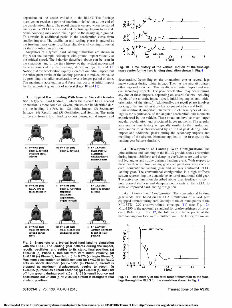
3.1 General Description of Example Rotorcraft andLanding Conditions. To underscore the landing performance ofrotorcraft with an RLLG system, an OH-6A sized helicopter [34]was considered. A schematic view of the example helicopter withthe RLLG is shown in Figs. 7 and 8. Ground terra mechanics weredefined by setting the stiffness and damping coefficients of thecontact model to large values, yielding a nearly rigid ground sur-face. Landing events were initiated by releasing the aircraft intofree fall from a specified initial height. A hard landing is restrictedto scenarios that do not result in any localized yielding in the land-ing gear, which limits the impact speed. The limit was estimatedvia finite element analysis (FEA) simulations to be about 12 ft/s
for the example helicopter with traditional skid gear. This speed isreferred to as the critical speed. At larger impact speeds, yieldingwould occur resulting in permanent damage to traditional landinggear.
In addition to the vertical speed, other important initial condi-tions include the lateral and longitudinal velocity of the aircraft’smass center, the stance width of the landing gear, and the orienta-tion of the aircraft. The stance width of the landing gear, definedby the distance between the feet of the front legs, was controlledthrough the initial leg angles. The initial angles define the zero-load point of the rotational springs in the leg segment joints.Larger angles provide a wider stance, which has better stability,but less stroke. The orientation was defined by specifying rota-tions of the aircraft about the traditional roll and pitch axes in theaircraft frame. For general orientations, initial contact mayinvolve one or more legs.
3.2 Typical Level Hard Landing. A typical, level hard land-ing involves almost no rolling or pitching of the aircraft. Fourphases can be identified during the landing: (1) Free fall; (2)Deceleration; (3) Recoil; and (4) Oscillation and Settling. Thesephases can be described by the following characteristics. Duringfree fall, there is constant acceleration of the fuselage mass centerdue to gravity. During the deceleration phase, a large spike inacceleration occurs during initial contact. This corresponds topeak forces and moments on the RLLG and fuselage. The magni-tude of the acceleration decreases at a rate that is largely
Fig. 6 Controller state machine (a) and detailed decision tree (b)
Fig. 7 Schematic of the example rotorcraft equipped with theRLLG Fig. 8 Schematic of an RLLG leg
Journal of Dynamic Systems, Measurement, and Control MARCH 2016, Vol. 138 / 031003-5
Downloaded From: http://dynamicsystems.asmedigitalcollection.asme.org/ on 03/28/2016 Terms of Use: http://www.asme.org/about-asme/terms-of-use
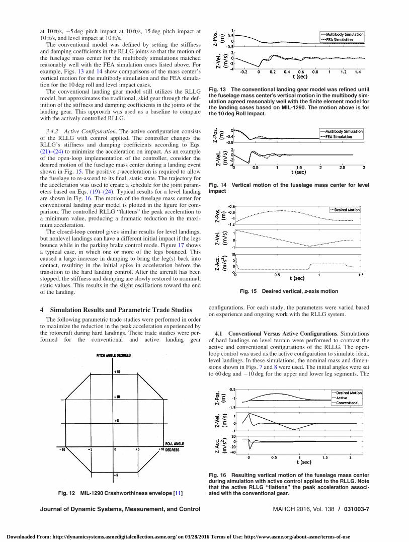
dependent on the stroke available to the RLLG. The fuselagemass center reaches a point of maximum deflection at the end ofthe deceleration phase. The recoil phase is entered when the storedenergy in the RLLG is released and the fuselage begins to ascend.Some bouncing may occur, due in part to the nearly rigid ground.This results in additional peaks in the acceleration curve fromsmaller impacts. The oscillation and settling phase is entered asthe fuselage mass center oscillates slightly until coming to rest atits static equilibrium position.
Snapshots of a typical hard landing simulation are shown inFig. 9 for the example helicopter with ground impact velocity atthe critical speed. The behavior described above can be seen inthe snapshots, and in the time history of the vertical motion andforce experienced by the fuselage, shown in Figs. 10 and 11.Notice that the acceleration rapidly increases on initial impact, butthe subsequent stroke of the landing gear acts to reduce this valueby providing a smaller acceleration over a longer period of time.The maximum acceleration and force that occur at initial impactare the important quantities of interest (Figs. 10 and 11).
3.3 Typical Hard Landing With General Aircraft Orienta-tion. A typical, hard landing in which the aircraft has a generalorientation is more complex. Several phases can be identified dur-ing the landing: (1) Free fall; (2) Initial Impact; (3) SecondaryImpacts; (4) Recoil; and (5) Oscillation and Settling. The maindifference from a level landing occurs during initial impact and
deceleration. Depending on the orientation, one or several legsmake contact during initial impact. Then, as the aircraft rotates,other legs make contact. This results in an initial impact and sev-eral secondary impacts. The peak deceleration may occur duringany one of these impacts, depending on several factors, includingweight of the aircraft, impact speed, initial leg angles, and initialorientation of the aircraft. Additionally, the recoil phase involvesrocking of the aircraft as it pitches and/or rolls back and forth.
An additional, important characteristic of these types of land-ings is the significance of the angular acceleration and momentsexperienced by the vehicle. These situations involve much largerangular acceleration and associated larger moments. The angularacceleration time history is typically similar to the translationalacceleration. It is characterized by an initial peak during initialimpact and additional peaks during the secondary impacts andrecoiling of the aircraft. Moments applied to the fuselage by thelanding gear behave similarly.
3.4 Development of Landing Gear Configurations. Thejoint stiffness and damping in the RLLG provide shock absorptionduring impact. Stiffness and damping coefficients are used to con-trol leg angles and stroke during a landing event. With respect tothese coefficients, two landing gear configurations were consid-ered: conventional landing gear and actively controlled RLLGlanding gear. The conventional configuration is a high stiffnesssystem representing the dynamic behavior of traditional skid gear.The active configuration described above uses feedback to com-pute desired stiffness and damping coefficients in the RLLG toachieve improved hard landing mitigation.
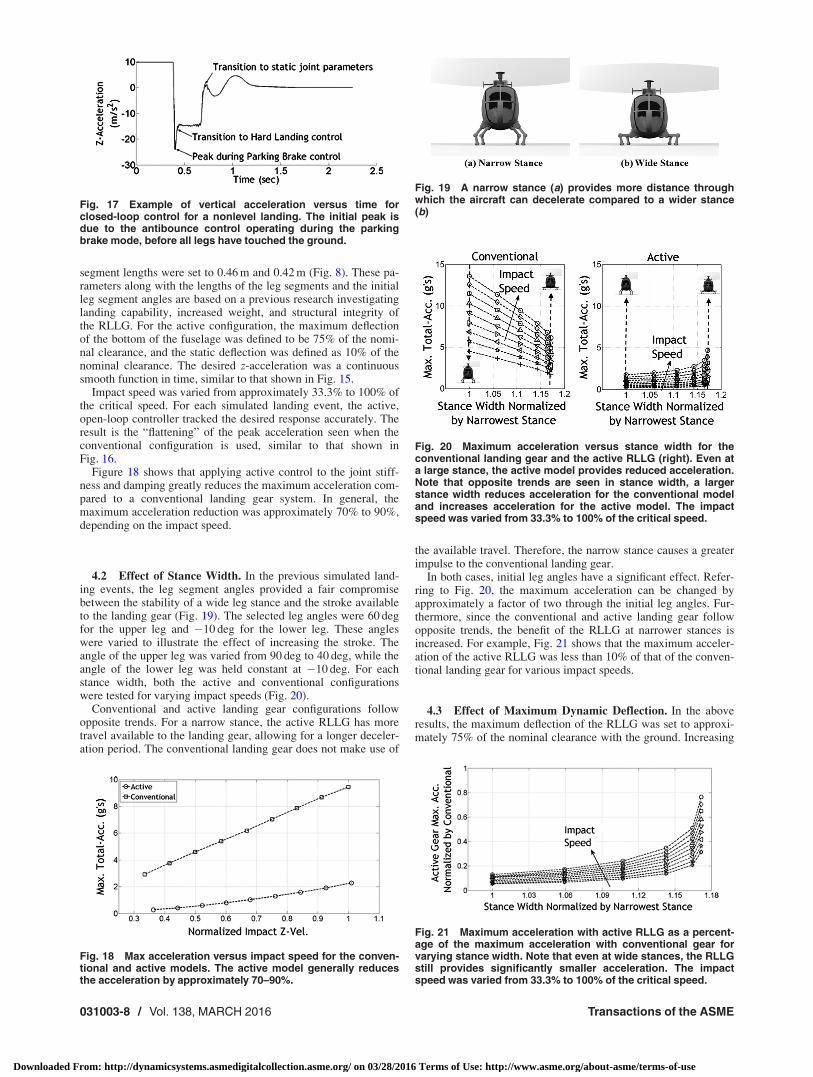
3.4.1 Conventional Configuration. The conventional landinggear model was based on the FEA simulations of a skid gearequipped aircraft during hard landings at the extreme points of theMIL-STD 1290 crashworthiness envelope [11] (see Fig. 12).MIL-1290 is the governing standard for crashworthiness of rotor-craft. Referring to Fig. 12, the following extreme points of thehard landing envelope were simulated via FEA: 10 deg roll impact
Fig. 9 Snapshots of a typical level hard landing simulationwith the RLLG. The landing gear deflects during the impact,recoils, oscillates, and settles to its static, final position. (a)t 5 0.000 (s) Phase 1, free fall with zero initial velocity; (b)t 5 0.120 (s) Phase 1, free fall; (c) t 5 0.370 (s) begin Phase 2,Maximum deceleration on initial contact; (d) t 5 0.385 (s) RLLGacts as shock absorber; (e) t 5 0.555 (s) Phase 3, aircraft isstopped at maximum displacement, begins to recoil; (f)t 5 0.625 (s) recoil as aircraft ascends; (g) t 5 0.800 (s) small liftoff from ground during recoil; (h) t 5 1.155 (s) small bounce andoscillations occur; and (i) t 5 2.000 (s) aircraft is brought to restat static position.
Fig. 10 Time history of the vertical motion of the fuselagemass center for the hard landing simulation shown in Fig. 9
Fig. 11 Time history of the total force transmitted to the fuse-lage through the RLLG for the simulation shown in Fig. 9
031003-6 / Vol. 138, MARCH 2016 Transactions of the ASME
Downloaded From: http://dynamicsystems.asmedigitalcollection.asme.org/ on 03/28/2016 Terms of Use: http://www.asme.org/about-asme/terms-of-use
at 10 ft/s, �5 deg pitch impact at 10 ft/s, 15 deg pitch impact at10 ft/s, and level impact at 10 ft/s.
The conventional model was defined by setting the stiffnessand damping coefficients in the RLLG joints so that the motion ofthe fuselage mass center for the multibody simulations matchedreasonably well with the FEA simulation cases listed above. Forexample, Figs. 13 and 14 show comparisons of the mass center’svertical motion for the multibody simulation and the FEA simula-tion for the 10 deg roll and level impact cases.
The conventional landing gear model still utilizes the RLLGmodel, but approximates the traditional, skid gear through the def-inition of the stiffness and damping coefficients in the joints of thelanding gear. This approach was used as a baseline to comparewith the actively controlled RLLG.
3.4.2 Active Configuration. The active configuration consistsof the RLLG with control applied. The controller changes theRLLG’s stiffness and damping coefficients according to Eqs.(21)–(24) to minimize the acceleration on impact. As an exampleof the open-loop implementation of the controller, consider thedesired motion of the fuselage mass center during a landing eventshown in Fig. 15. The positive z-acceleration is required to allowthe fuselage to re-ascend to its final, static state. The trajectory forthe acceleration was used to create a schedule for the joint param-eters based on Eqs. (19)–(24). Typical results for a level landingare shown in Fig. 16. The motion of the fuselage mass center forconventional landing gear model is plotted in the figure for com-parison. The controlled RLLG “flattens” the peak acceleration toa minimum value, producing a dramatic reduction in the maxi-mum acceleration.
The closed-loop control gives similar results for level landings,but nonlevel landings can have a different initial impact if the legsbounce while in the parking brake control mode. Figure 17 showsa typical case, in which one or more of the legs bounced. Thiscaused a large increase in damping to bring the leg(s) back intocontact, resulting in the initial spike in acceleration before thetransition to the hard landing control. After the aircraft has beenstopped, the stiffness and damping are slowly restored to nominal,static values. This results in the slight oscillations toward the endof the landing.
4 Simulation Results and Parametric Trade Studies
The following parametric trade studies were performed in orderto maximize the reduction in the peak acceleration experienced bythe rotorcraft during hard landings. These trade studies were per-formed for the conventional and active landing gear
configurations. For each study, the parameters were varied basedon experience and ongoing work with the RLLG system.
4.1 Conventional Versus Active Configurations. Simulationsof hard landings on level terrain were performed to contrast theactive and conventional configurations of the RLLG. The open-loop control was used as the active configuration to simulate ideal,level landings. In these simulations, the nominal mass and dimen-sions shown in Figs. 7 and 8 were used. The initial angles were setto 60 deg and �10 deg for the upper and lower leg segments. The
Fig. 12 MIL-1290 Crashworthiness envelope [11]
Fig. 13 The conventional landing gear model was refined untilthe fuselage mass center’s vertical motion in the multibody sim-ulation agreed reasonably well with the finite element model forthe landing cases based on MIL-1290. The motion above is forthe 10 deg Roll Impact.
Fig. 14 Vertical motion of the fuselage mass center for levelimpact
Fig. 15 Desired vertical, z-axis motion
Fig. 16 Resulting vertical motion of the fuselage mass centerduring simulation with active control applied to the RLLG. Notethat the active RLLG “flattens” the peak acceleration associ-ated with the conventional gear.
Journal of Dynamic Systems, Measurement, and Control MARCH 2016, Vol. 138 / 031003-7
Downloaded From: http://dynamicsystems.asmedigitalcollection.asme.org/ on 03/28/2016 Terms of Use: http://www.asme.org/about-asme/terms-of-use
segment lengths were set to 0.46 m and 0.42 m (Fig. 8). These pa-rameters along with the lengths of the leg segments and the initialleg segment angles are based on a previous research investigatinglanding capability, increased weight, and structural integrity ofthe RLLG. For the active configuration, the maximum deflectionof the bottom of the fuselage was defined to be 75% of the nomi-nal clearance, and the static deflection was defined as 10% of thenominal clearance. The desired z-acceleration was a continuoussmooth function in time, similar to that shown in Fig. 15.
Impact speed was varied from approximately 33.3% to 100% ofthe critical speed. For each simulated landing event, the active,open-loop controller tracked the desired response accurately. Theresult is the “flattening” of the peak acceleration seen when theconventional configuration is used, similar to that shown inFig. 16.
Figure 18 shows that applying active control to the joint stiff-ness and damping greatly reduces the maximum acceleration com-pared to a conventional landing gear system. In general, themaximum acceleration reduction was approximately 70% to 90%,depending on the impact speed.
4.2 Effect of Stance Width. In the previous simulated land-ing events, the leg segment angles provided a fair compromisebetween the stability of a wide leg stance and the stroke availableto the landing gear (Fig. 19). The selected leg angles were 60 degfor the upper leg and �10 deg for the lower leg. These angleswere varied to illustrate the effect of increasing the stroke. Theangle of the upper leg was varied from 90 deg to 40 deg, while theangle of the lower leg was held constant at �10 deg. For eachstance width, both the active and conventional configurationswere tested for varying impact speeds (Fig. 20).
Conventional and active landing gear configurations followopposite trends. For a narrow stance, the active RLLG has moretravel available to the landing gear, allowing for a longer deceler-ation period. The conventional landing gear does not make use of
the available travel. Therefore, the narrow stance causes a greaterimpulse to the conventional landing gear.
In both cases, initial leg angles have a significant effect. Refer-ring to Fig. 20, the maximum acceleration can be changed byapproximately a factor of two through the initial leg angles. Fur-thermore, since the conventional and active landing gear followopposite trends, the benefit of the RLLG at narrower stances isincreased. For example, Fig. 21 shows that the maximum acceler-ation of the active RLLG was less than 10% of that of the conven-tional landing gear for various impact speeds.
4.3 Effect of Maximum Dynamic Deflection. In the aboveresults, the maximum deflection of the RLLG was set to approxi-mately 75% of the nominal clearance with the ground. Increasing
Fig. 17 Example of vertical acceleration versus time forclosed-loop control for a nonlevel landing. The initial peak isdue to the antibounce control operating during the parkingbrake mode, before all legs have touched the ground.
Fig. 18 Max acceleration versus impact speed for the conven-tional and active models. The active model generally reducesthe acceleration by approximately 70–90%.
Fig. 19 A narrow stance (a) provides more distance throughwhich the aircraft can decelerate compared to a wider stance(b)
Fig. 20 Maximum acceleration versus stance width for theconventional landing gear and the active RLLG (right). Even ata large stance, the active model provides reduced acceleration.Note that opposite trends are seen in stance width, a largerstance width reduces acceleration for the conventional modeland increases acceleration for the active model. The impactspeed was varied from 33.3% to 100% of the critical speed.
Fig. 21 Maximum acceleration with active RLLG as a percent-age of the maximum acceleration with conventional gear forvarying stance width. Note that even at wide stances, the RLLGstill provides significantly smaller acceleration. The impactspeed was varied from 33.3% to 100% of the critical speed.
031003-8 / Vol. 138, MARCH 2016 Transactions of the ASME
Downloaded From: http://dynamicsystems.asmedigitalcollection.asme.org/ on 03/28/2016 Terms of Use: http://www.asme.org/about-asme/terms-of-use
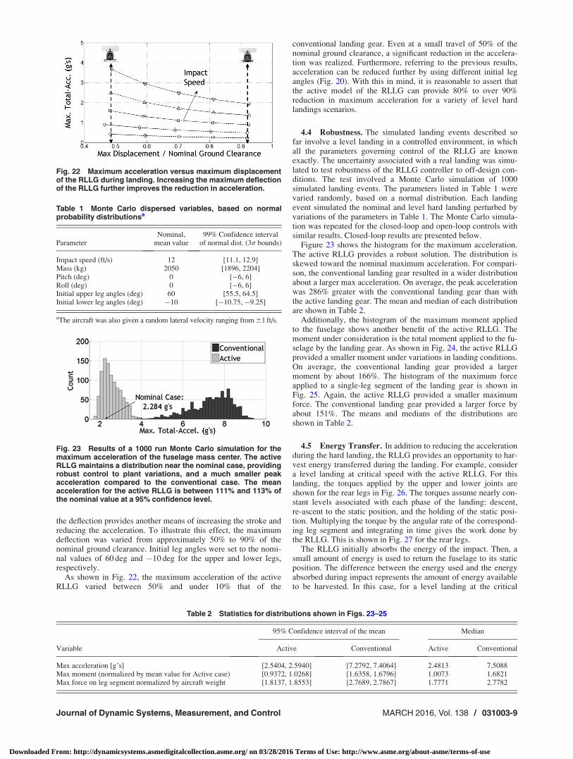
the deflection provides another means of increasing the stroke andreducing the acceleration. To illustrate this effect, the maximumdeflection was varied from approximately 50% to 90% of thenominal ground clearance. Initial leg angles were set to the nomi-nal values of 60 deg and �10 deg for the upper and lower legs,respectively.
As shown in Fig. 22, the maximum acceleration of the activeRLLG varied between 50% and under 10% that of the
conventional landing gear. Even at a small travel of 50% of thenominal ground clearance, a significant reduction in the accelera-tion was realized. Furthermore, referring to the previous results,acceleration can be reduced further by using different initial legangles (Fig. 20). With this in mind, it is reasonable to assert thatthe active model of the RLLG can provide 80% to over 90%reduction in maximum acceleration for a variety of level hardlandings scenarios.
4.4 Robustness. The simulated landing events described sofar involve a level landing in a controlled environment, in whichall the parameters governing control of the RLLG are knownexactly. The uncertainty associated with a real landing was simu-lated to test robustness of the RLLG controller to off-design con-ditions. The test involved a Monte Carlo simulation of 1000simulated landing events. The parameters listed in Table 1 werevaried randomly, based on a normal distribution. Each landingevent simulated the nominal and level hard landing perturbed byvariations of the parameters in Table 1. The Monte Carlo simula-tion was repeated for the closed-loop and open-loop controls withsimilar results. Closed-loop results are presented below.
Figure 23 shows the histogram for the maximum acceleration.The active RLLG provides a robust solution. The distribution isskewed toward the nominal maximum acceleration. For compari-son, the conventional landing gear resulted in a wider distributionabout a larger max acceleration. On average, the peak accelerationwas 286% greater with the conventional landing gear than withthe active landing gear. The mean and median of each distributionare shown in Table 2.
Additionally, the histogram of the maximum moment appliedto the fuselage shows another benefit of the active RLLG. Themoment under consideration is the total moment applied to the fu-selage by the landing gear. As shown in Fig. 24, the active RLLGprovided a smaller moment under variations in landing conditions.On average, the conventional landing gear provided a largermoment by about 166%. The histogram of the maximum forceapplied to a single-leg segment of the landing gear is shown inFig. 25. Again, the active RLLG provided a smaller maximumforce. The conventional landing gear provided a larger force byabout 151%. The means and medians of the distributions areshown in Table 2.
4.5 Energy Transfer. In addition to reducing the accelerationduring the hard landing, the RLLG provides an opportunity to har-vest energy transferred during the landing. For example, considera level landing at critical speed with the active RLLG. For thislanding, the torques applied by the upper and lower joints areshown for the rear legs in Fig. 26. The torques assume nearly con-stant levels associated with each phase of the landing: descent,re-ascent to the static position, and the holding of the static posi-tion. Multiplying the torque by the angular rate of the correspond-ing leg segment and integrating in time gives the work done bythe RLLG. This is shown in Fig. 27 for the rear legs.
The RLLG initially absorbs the energy of the impact. Then, asmall amount of energy is used to return the fuselage to its staticposition. The difference between the energy used and the energyabsorbed during impact represents the amount of energy availableto be harvested. In this case, for a level landing at the critical
Fig. 22 Maximum acceleration versus maximum displacementof the RLLG during landing. Increasing the maximum deflectionof the RLLG further improves the reduction in acceleration.
Table 1 Monte Carlo dispersed variables, based on normalprobability distributionsa
ParameterNominal,
mean value99% Confidence interval
of normal dist. (3r bounds)
Impact speed (ft/s) 12 [11.1, 12.9]Mass (kg) 2050 [1896, 2204]Pitch (deg) 0 [�6, 6]Roll (deg) 0 [�6, 6]Initial upper leg angles (deg) 60 [55.5, 64.5]Initial lower leg angles (deg) �10 [�10.75, �9.25]
aThe aircraft was also given a random lateral velocity ranging from 61 ft/s.
Fig. 23 Results of a 1000 run Monte Carlo simulation for themaximum acceleration of the fuselage mass center. The activeRLLG maintains a distribution near the nominal case, providingrobust control to plant variations, and a much smaller peakacceleration compared to the conventional case. The meanacceleration for the active RLLG is between 111% and 113% ofthe nominal value at a 95% confidence level.
Table 2 Statistics for distributions shown in Figs. 23–25
95% Confidence interval of the mean Median
Variable Active Conventional Active Conventional
Max acceleration [g’s] [2.5404, 2.5940] [7.2792, 7.4064] 2.4813 7.5088Max moment (normalized by mean value for Active case) [0.9372, 1.0268] [1.6358, 1.6796] 1.0073 1.6821Max force on leg segment normalized by aircraft weight [1.8137, 1.8553] [2.7689, 2.7867] 1.7771 2.7782
Journal of Dynamic Systems, Measurement, and Control MARCH 2016, Vol. 138 / 031003-9
Downloaded From: http://dynamicsystems.asmedigitalcollection.asme.org/ on 03/28/2016 Terms of Use: http://www.asme.org/about-asme/terms-of-use
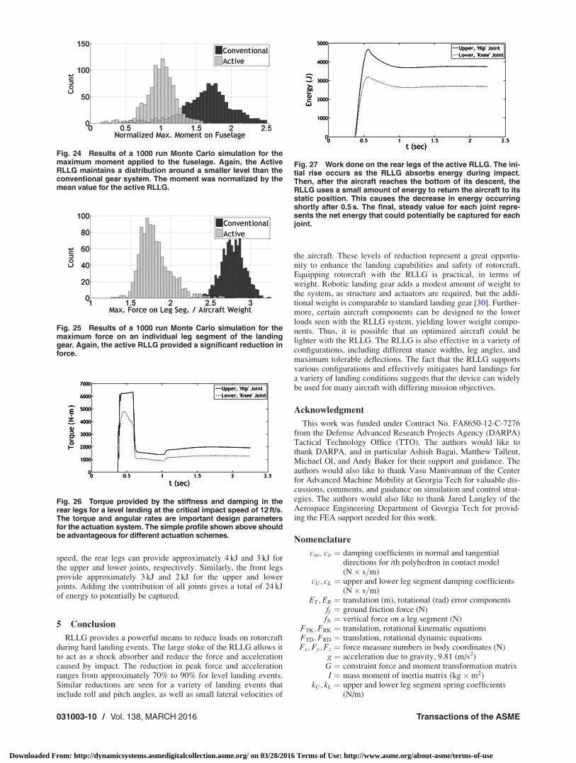
speed, the rear legs can provide approximately 4 kJ and 3 kJ forthe upper and lower joints, respectively. Similarly, the front legsprovide approximately 3 kJ and 2 kJ for the upper and lowerjoints. Adding the contribution of all joints gives a total of 24 kJof energy to potentially be captured.
5 Conclusion
RLLG provides a powerful means to reduce loads on rotorcraftduring hard landing events. The large stoke of the RLLG allows itto act as a shock absorber and reduce the force and accelerationcaused by impact. The reduction in peak force and accelerationranges from approximately 70% to 90% for level landing events.Similar reductions are seen for a variety of landing events thatinclude roll and pitch angles, as well as small lateral velocities of
the aircraft. These levels of reduction represent a great opportu-nity to enhance the landing capabilities and safety of rotorcraft.Equipping rotorcraft with the RLLG is practical, in terms ofweight. Robotic landing gear adds a modest amount of weight tothe system, as structure and actuators are required, but the addi-tional weight is comparable to standard landing gear [30]. Further-more, certain aircraft components can be designed to the lowerloads seen with the RLLG system, yielding lower weight compo-nents. Thus, it is possible that an optimized aircraft could belighter with the RLLG. The RLLG is also effective in a variety ofconfigurations, including different stance widths, leg angles, andmaximum tolerable deflections. The fact that the RLLG supportsvarious configurations and effectively mitigates hard landings fora variety of landing conditions suggests that the device can widelybe used for many aircraft with differing mission objectives.
Acknowledgment
This work was funded under Contract No. FA8650-12-C-7276from the Defense Advanced Research Projects Agency (DARPA)Tactical Technology Office (TTO). The authors would like tothank DARPA, and in particular Ashish Bagai, Matthew Tallent,Michael Ol, and Andy Baker for their support and guidance. Theauthors would also like to thank Vasu Manivannan of the Centerfor Advanced Machine Mobility at Georgia Tech for valuable dis-cussions, comments, and guidance on simulation and control strat-egies. The authors would also like to thank Jared Langley of theAerospace Engineering Department of Georgia Tech for provid-ing the FEA support needed for this work.
Nomenclature
cin; cit ¼ damping coefficients in normal and tangentialdirections for ith polyhedron in contact model(N� s=m)
cU; cL ¼ upper and lower leg segment damping coefficients(N� s=m)
ET ;ER ¼ translation (m), rotational (rad) error componentsff ¼ ground friction force (N)fN ¼ vertical force on a leg segment (N)
FTK;FRK ¼ translation, rotational kinematic equationsFTD;FRD ¼ translation, rotational dynamic equationsFx;Fy;Fz ¼ force measure numbers in body coordinates (N)
g ¼ acceleration due to gravity, 9.81 (m/s2)G ¼ constraint force and moment transformation matrixI ¼ mass moment of inertia matrix (kg�m2)
kU; kL ¼ upper and lower leg segment spring coefficients(N/m)
Fig. 24 Results of a 1000 run Monte Carlo simulation for themaximum moment applied to the fuselage. Again, the ActiveRLLG maintains a distribution around a smaller level than theconventional gear system. The moment was normalized by themean value for the active RLLG.
Fig. 25 Results of a 1000 run Monte Carlo simulation for themaximum force on an individual leg segment of the landinggear. Again, the active RLLG provided a significant reduction inforce.
Fig. 26 Torque provided by the stiffness and damping in therear legs for a level landing at the critical impact speed of 12 ft/s.The torque and angular rates are important design parametersfor the actuation system. The simple profile shown above shouldbe advantageous for different actuation schemes.
Fig. 27 Work done on the rear legs of the active RLLG. The ini-tial rise occurs as the RLLG absorbs energy during impact.Then, after the aircraft reaches the bottom of its descent, theRLLG uses a small amount of energy to return the aircraft to itsstatic position. This causes the decrease in energy occurringshortly after 0.5 s. The final, steady value for each joint repre-sents the net energy that could potentially be captured for eachjoint.
031003-10 / Vol. 138, MARCH 2016 Transactions of the ASME
Downloaded From: http://dynamicsystems.asmedigitalcollection.asme.org/ on 03/28/2016 Terms of Use: http://www.asme.org/about-asme/terms-of-use
kin; kit ¼ spring coefficients in normal and tangential direc-tions for ith polyhedron in contact model (N/m)
‘U; ‘L ¼ upper, lower lengths of leg segmentsm ¼ mass (kg)
Mx;My;Mz ¼ moment measure numbers in body coordinates(N�m)
p; q; r ¼ inertial angular rate measure numbers in bodycoordinates (rad/s)
q0;q1;q2;q3 ¼ quaternion parameters describing orientation ofbody in inertial frame (nd)
R ¼ proportionality constant between stiffness anddamping coefficients (s)
s*
in; s*
it ¼ ith spring displacement in contact model in normaland tangential directions (m)
Sxi¼ skew symmetric cross product operator acting on
angular ratesTB ¼ transformation matrix from inertial to body refer-
ence frameu; v;w ¼ inertial velocity vector measure numbers in body
coordinates (m/s)U ¼ constraint force (N) and moment vector (N�m)uc ¼ control input (desired acceleration) (m/s2)ui ¼ absolute velocity of contact point for ith polyhedron
in the soft contact modelwi ¼ absolute velocity of surface element associated
with the ith polyhedron in soft contact modelx; y; z ¼ position vector measure numbers in inertial
reference frame (m)X ¼ state vectorc ¼ pseudo controln ¼ damping ratio (nd)
hU; hL ¼ upper, lower angles of leg segments with respect tovertical (rad)
xn ¼ natural frequency (rad/s)
References[1] Sharp, C. S., Shakernia, O., and Sastry, S. S., 2001, “A Vision System for Land-
ing an Unmanned Aerial Vehicle,” IEEE International Conference on Roboticsand Automation, Seoul, South Korea, pp. 1720–1727.
[2] Sykora, B., 2009, “Rotorcraft Visual Situational Awareness, Solving the Pilot-age Problem for Landing in Degraded Visual Environments,” American Heli-copter Society 65th Annual Forum, AHS, Ontario, CA.
[3] Taylor, T., 2009, “Rotorcraft Visual Situational Awareness (VSA): Solving thePilotage Problem for Landing in Degraded Visual Environments,” Proc. SPIE,7328, p. 73280G-1.
[4] Templeton, T., 2007, Autonomous Vision-Based Rotorcraft Landing and Accu-rate Aerial Terrain Mapping in an Unknown Environment, University of Cali-fornia at Berkeley, Berkeley, CA.
[5] Takahashi, M. D., Abershitz, A., Rubinets, R., and Whalley, M. S., 2013,“Evaluation of Safe Landing Area Determination Algorithms for AutonomousRotorcraft Using Site Benchmarking,” J. Am. Helicopter Soc., 58(3), pp. 1–13.
[6] Coltman, J. W., Bolukbasi, A. O., and Laananen, D. H., 1985, Analysis ofRotorcraft Crash Dynamics for Development of Improved CrashworthinessDesign Criteria, Simula, Inc., Tempe, AZ.
[7] Shanahan, D. F., and Mastroianni, G. R., 1984, “Spinal Injury in a U.S. ArmyLight Observation Helicopter,” Aviat. Space Environ. Med., 55(1), pp. 32–40.
[8] Iseler, L., and De Maio, J., 2002, An Analysis of U.S. Civil Rotorcraft Accidentsby Cost and Injury (1990–1996), National Aeronautics and Space Administra-tion AMES Research Center, Moffett Field, CA.
[9] Couch, M., and Lindell, D., 2010, Study on Rotorcraft Safety and Survivability,Defense Acquisition University, Fort Belvoir, VA.
[10] Shanahan, D. F., 1993, Basic Principles of Helicopter Crashworthiness, ArmyAeromedical Research Laboratory, Fort Rucker, AL.
[11] Standard Military, 1988, MIL_STD_1290 (A) Light Fixed and Rotary-Wing Air-craft Crash Resistance, Department of Defense, Washington, DC.
[12] Tho, C. H., Sparks, C. E., Sareen, A. K., Smith, M. R., and Johnson, C., 2004,“Efficient Helicopter Skid Landing Gear Dynamic Drop Simulation Using LS-DYN,” J. Am. Helicopter Soc., 49(4), pp. 483–492.
[13] Airoldi, A., and Lanzi, L., 2005, “Multi-Objective Genetic Optimization forHelicopter Skid Landing Gears,” AIAA Paper No. 2005-2310.
[14] Chernoff, M., 1962, “Analysis and Design of Skid Gears for Level Landing,” J.Am. Helicopter Soc., 7(1), pp. 33–39.
[15] Stephens, B. E., and Evans, W. L., 1999, “Application of Skid Landing GearDynamic Drop Simulation,” American Helicopter Society 55th Annual Forum,AHS, Montreal, Canada.
[16] Littell, J., 2011, “Full-Scale Crash Test of an MD-500 Helicopter,” 67th Ameri-can Helicopter Society Annual Forum, AHS, Virginia Beach, VA.
[17] Caprile, C., Airolid, A., and Janszen, G., 1999, “Multi-Body Simulation of aHelicopter Landing With Skid Landing Gear in Various Attitudes and Soil Con-ditions,” 25th European Rotorcraft Forum, Rome, Italy, p. G-12.
[18] Kellas, S., Jackson, K. E., and Littell, J. D., 2010, “Full-Scale Crash Test of anMD-500 Helicopter With Deployable Energy Absorbers,” American HelicopterSociety 66th Annual Forum and Technology Display, AHS, Phoenix, AZ.
[19] Jackson, K. E., and Yvonne, T. F., 2008, “Comparison of ALE and SPH Simu-lations of Vertical Drop Tests of a Composite Fuselage Section Into Water,”10th International LS-DYNA Users Conference, Dearborn, MI, Document IDNo. 20080022946.
[20] Kim, H., and Kirby, B. P. D., 2006, “Investigation of External Airbags forRotorcraft Crashworthiness,” J. Aircr., 43(3), pp. 809–816.
[21] Airoldi, A., and Janszen, G., 2005, “A Design Solution for a Crashworthy Land-ing Gear With a New Triggering Mechanism for the Plastic Collapse of Metal-lic Tubes,” Aerosp. Sci. Technol., 9(5), pp. 445–455.
[22] Fagan, C. H., and Lynn, R. R., 1973, “Energy Absorbing Landing Gear,” U.S.Patent No. 3,716,208, Feb. 13.
[23] Gentile, D. M., 1998, “Emergency Soft-Landing System for Rotor-Type Air-craft,” U.S. Patent No. US5836544 A, Nov. 17.
[24] Logan, A. H., and Wagner, R. A., 1985, “For Use in an Aircraft,” U.S. PatentNo. US4519559 A, May 28.
[25] Mikulowski, G., and Holnicki-Szulc, J., 2004, “Adaptive Aircraft ShockAbsorbers,” Third European Conference on Structural Control, Jadwisin, Sept.2–5.
[26] Sandy, D. F., and Furnes, K. M., 1999, “Energy Absorbing Landing Gear/TailSkid,” U.S. Patent No. US5927646 A, Jul. 27.
[27] Carter, Jr. J. W., 1999, “Crashworthy Landing Gear Shock,” U.S. Patent No.US5944283 A, Aug. 31.
[28] Shwayder, W., 1985, “Helicopter Landing Skid Shoe Pad,” U.S. Patent No.US4544116 A, Oct. 1.
[29] Smith, M. R., and Cheng-Ho Tho, S. C., 2011, “Crash Attenuation System forAircraft,” U.S. Patent No. US7954752 B2, Jun. 7.
[30] Manivannan, V., Langley, J. P., Costello, M. F., and Ruzzene, M., 2013,“Rotorcraft Slope Landings With Articulated Landing Gear,” AIAA Paper No.2013-5160.
[31] Leylek, E., Ward, M., and Costello, M., 2012, “Flight Dynamic Simulation forMultibody Aircraft Configurations,” J. Guid. Control Dyn., 35(6), pp.1828–1842.
[32] Goyal, S., Pinson, E. N., and Sinden, F. W., 1994, “Simulation of Dynamics ofInteracting Rigid Bodies Including Friction I: General Problem and ContactModel,” Eng. Comput., 10(3), pp. 162–174.
[33] Goyal, S., Pinson, E. N., and Sinden, F. W., 1994, “Simulation of Dynamics ofInteracting Rigid Bodies Including Friction II: Software System Design andImplementation,” Eng. Comput., 10(3), pp. 175–195.
[34] 1990, Operators Manual: Helicopter, Observation OH-6A, Headquarters,Department of the Army.
Journal of Dynamic Systems, Measurement, and Control MARCH 2016, Vol. 138 / 031003-11
Downloaded From: http://dynamicsystems.asmedigitalcollection.asme.org/ on 03/28/2016 Terms of Use: http://www.asme.org/about-asme/terms-of-use