Embed Size (px)
Citation preview
GuestWorks® and DEFINITY® SystemsTechnician Handbook for Hospitality Installations
555-231-743Issue 2
December 2001Compas ID 88500
Copyright 2001, Avaya Inc.All Rights Reserved
Notice
Every effort was made to ensure that the information in this document was complete and accurate at the time of printing. However, informa-tion is subject to change.
Preventing Toll Fraud
“Toll fraud” is the unauthorized use of your telecommunications sys-tem by an unauthorized party (for example, a person who is not a cor-porate employee, agent, subcontractor, or is not working on your company's behalf). Be aware that there may be a risk of toll fraud associated with your system and that, if toll fraud occurs, it can result in substantial additional charges for your telecommunications ser-vices.
Avaya Fraud Intervention
If you suspect that you are being victimized by toll fraud and you need technical assistance or support, in the United States and Canada, call the Technical Service Center's Toll Fraud Intervention Hotline at 1-800-643-2353. For additional support telephone numbers, see the Avaya web site:http://www.avaya.com Click on Support, click on Escalation Lists US and International. This web site includes phone numbers for escalation within the United States. For escalation phone numbers outside the United States, click on Global Escalation List.
Providing Telecommunications Security
Telecommunications security (of voice, data, and/or video communi-cations) is the prevention of any type of intrusion to (that is, either unauthorized or malicious access to or use of) your company's tele-communications equipment by some party.
Your company's “telecommunications equipment” includes both this Avaya product and any other voice/data/video equipment that could be accessed via this Avaya product (that is, “networked equipment”).
An “outside party” is anyone who is not a corporate employee, agent, subcontractor, or is not working on your company's behalf. Whereas, a “malicious party” is anyone (including someone who may be other-wise authorized) who accesses your telecommunications equipment with either malicious or mischievous intent.
Such intrusions may be either to/through synchronous (time-multi-plexed and/or circuit-based) or asynchronous (character-, message-, or packet-based) equipment or interfaces for reasons of:
• Utilization (of capabilities special to the accessed equipment)• Theft (such as, of intellectual property, financial assets, or toll-
facility access)• Eavesdropping (privacy invasions to humans)• Mischief (troubling, but apparently innocuous, tampering)• Harm (such as harmful tampering, data loss or alteration,
regardless of motive or intent)Be aware that there may be a risk of unauthorized intrusions associ-ated with your system and/or its networked equipment. Also realize that, if such an intrusion should occur, it could result in a variety of losses to your company (including but not limited to, human/data pri-vacy, intellectual property, material assets, financial resources, labor costs, and/or legal costs).
Your Responsibility for Your Company’s Telecommunications Security
The final responsibility for securing both this system and its net-worked equipment rests with you - an Avaya customer's system administrator, your telecommunications peers, and your managers. Base the fulfillment of your responsibility on acquired knowledge and resources from a variety of sources including but not limited to:
• Installation documents• System administration documents• Security documents• Hardware-/software-based security tools• Shared information between you and your peers• Telecommunications security experts
To prevent intrusions to your telecommunications equipment, you and your peers should carefully program and configure:
• your Avaya-provided telecommunications systems and their interfaces
• your Avaya-provided software applications, as well as their underlying hardware/software platforms and interfaces
• any other equipment networked to your Avaya products.
How to get help
For support phone numbers, see the Avaya web site:http://www.avaya.com Click on Support, click on Escalation Lists US and International. This web site includes phone numbers for escalation within the United States. For escalation phone numbers outside the United States, click on Global Escalation List.
Standards Compliance
Avaya Inc. is not responsible for any radio or television interference caused by unauthorized modifications of this equipment or the substi-tution or attachment of connecting cables and equipment other than those specified by Avaya Inc. The correction of interference caused by such unauthorized modifications, substitution or attachment will be the responsibility of the user. Pursuant to Part 15 of the Federal Com-munications Commission (FCC) Rules, the user is cautioned that changes or modifications not expressly approved by Avaya Inc. could void the user’s authority to operate this equipment.The equipment described in this manual complies with standards of the following organizations and laws, as applicable:
• Australian Communications Agency (ACA)• American National Standards Institute (ANSI)• Canadian Standards Association (CSA)• Committee for European Electrotechnical Standardization
(CENELEC) – European Norms (EN’s)• Digital Private Network Signaling System (DPNSS)• European Computer Manufacturers Association (ECMA)• European Telecommunications Standards Institute (ETSI)• FCC Rules Parts 15 and 68• International Electrotechnical Commission (IEC)• International Special Committee on Radio Interference
(CISPR)• International Telecommunications Union - Telephony (ITU-T)• ISDN PBX Network Specification (IPNS)• National ISDN-1• National ISDN-2• Underwriters Laboratories (UL)
Product Safety Standards
This product complies with and conforms to the following interna-tional Product Safety standards as applicable:
Safety of Information Technology Equipment, IEC 60950, 3rd Edition including all relevant national deviations as listed in Compliance with IEC for Electrical Equipment (IECEE) CB-96A.
Safety of Laser products, equipment classification and requirements:• IEC 60825-1, 1.1 Edition• Safety of Information Technology Equipment, CAN/CSA-
C22.2 No. 60950-00 / UL 60950, 3rd Edition• Safety Requirements for Customer Equipment, ACA Technical
Standard (TS) 001 - 1997 • One or more of the following Mexican national standards, as
applicable: NOM 001 SCFI 1993, NOM SCFI 016 1993, NOM 019 SCFI 1998
Electromagnetic Compatibility (EMC) Standards
This product complies with and conforms to the following interna-tional EMC standards and all relevant national deviations:
Limits and Methods of Measurement of Radio Interference of Infor-mation Technology Equipment, CISPR 22:1997 and EN55022:1998.
Information Technology Equipment – Immunity Characteristics – Limits and Methods of Measurement, CISPR 24:1997 and EN55024:1998, including:
• Electrostatic Discharge (ESD) IEC 61000-4-2• Radiated Immunity IEC 61000-4-3• Electrical Fast Transient IEC 61000-4-4• Lightning Effects IEC 61000-4-5• Conducted Immunity IEC 61000-4-6• Mains Frequency Magnetic Field IEC 61000-4-8• Voltage Dips and Variations IEC 61000-4-11• Powerline Harmonics IEC 61000-3-2• Voltage Fluctuations and Flicker IEC 61000-3-3
Federal Communications Commission Statement
Part 15:
Part 68: Answer-Supervision Signaling. Allowing this equipment to be operated in a manner that does not provide proper answer-supervi-sion signaling is in violation of Part 68 rules. This equipment returns answer-supervision signals to the public switched network when:
• answered by the called station, • answered by the attendant, or • routed to a recorded announcement that can be administered by
the customer premises equipment (CPE) user. This equipment returns answer-supervision signals on all direct inward dialed (DID) calls forwarded back to the public switched tele-phone network. Permissible exceptions are:
• A call is unanswered.• A busy tone is received.• A reorder tone is received.
Avaya attests that this registered equipment is capable of providing users access to interstate providers of operator services through the use of access codes. Modification of this equipment by call aggregators to block access dialing codes is a violation of the Telephone Operator Consumers Act of 1990.
This equipment complies with Part 68 of the FCC Rules. On the rear of this equipment is a label that contains, among other information, the FCC registration number and ringer equivalence number (REN) for this equipment. If requested, this information must be provided to the telephone company.
The REN is used to determine the quantity of devices which may be connected to the telephone line. Excessive RENs on the telephone line may result in devices not ringing in response to an incoming call. In most, but not all areas, the sum of RENs should not exceed 5.0. To be certain of the number of devices that may be connected to a line, as determined by the total RENs, contact the local telephone company.
REN is not required for some types of analog or digital facilities.
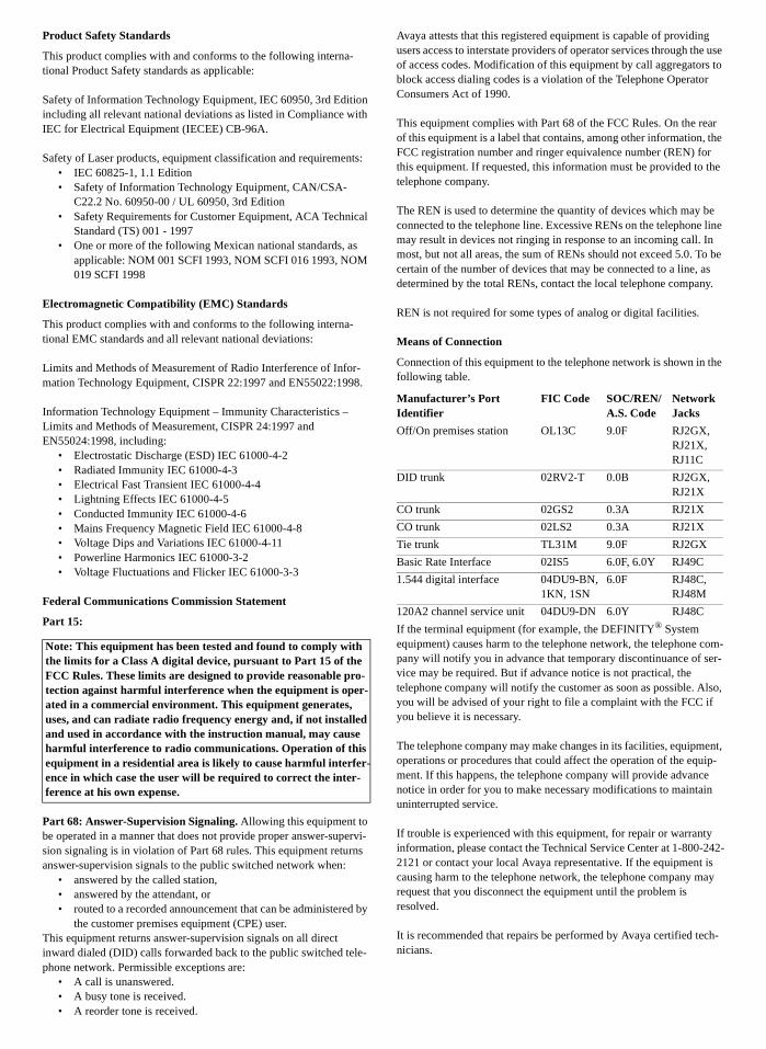
Means of Connection
Connection of this equipment to the telephone network is shown in the following table.
If the terminal equipment (for example, the DEFINITY® System equipment) causes harm to the telephone network, the telephone com-pany will notify you in advance that temporary discontinuance of ser-vice may be required. But if advance notice is not practical, the telephone company will notify the customer as soon as possible. Also, you will be advised of your right to file a complaint with the FCC if you believe it is necessary.
The telephone company may make changes in its facilities, equipment, operations or procedures that could affect the operation of the equip-ment. If this happens, the telephone company will provide advance notice in order for you to make necessary modifications to maintain uninterrupted service.
If trouble is experienced with this equipment, for repair or warranty information, please contact the Technical Service Center at 1-800-242-2121 or contact your local Avaya representative. If the equipment is causing harm to the telephone network, the telephone company may request that you disconnect the equipment until the problem is resolved.
It is recommended that repairs be performed by Avaya certified tech-nicians.
Note: This equipment has been tested and found to comply with the limits for a Class A digital device, pursuant to Part 15 of the FCC Rules. These limits are designed to provide reasonable pro-tection against harmful interference when the equipment is oper-ated in a commercial environment. This equipment generates, uses, and can radiate radio frequency energy and, if not installed and used in accordance with the instruction manual, may cause harmful interference to radio communications. Operation of this equipment in a residential area is likely to cause harmful interfer-ence in which case the user will be required to correct the inter-ference at his own expense.
Manufacturer’s Port Identifier
FIC Code SOC/REN/A.S. Code
Network Jacks
Off/On premises station OL13C 9.0F RJ2GX, RJ21X, RJ11C
DID trunk 02RV2-T 0.0B RJ2GX, RJ21X
CO trunk 02GS2 0.3A RJ21X
CO trunk 02LS2 0.3A RJ21X
Tie trunk TL31M 9.0F RJ2GX
Basic Rate Interface 02IS5 6.0F, 6.0Y RJ49C
1.544 digital interface 04DU9-BN, 1KN, 1SN
6.0F RJ48C, RJ48M
120A2 channel service unit 04DU9-DN 6.0Y RJ48C
The equipment cannot be used on public coin phone service provided by the telephone company. Connection to party line service is subject to state tariffs. Contact the state public utility commission, public ser-vice commission or corporation commission for information.This equipment, if it uses a telephone receiver, is hearing aid compati-ble.
Canadian Department of Communications (DOC) Interference Information
This Class A digital apparatus complies with Canadian ICES-003.
Cet appareil numérique de la classe A est conforme à la norme NMB-003 du Canada.
DECLARATIONS OF CONFORMITY
United States FCC Part 68 Supplier’s Declaration of Conformity (SDoC)
Avaya, Inc. in the United States of America hereby certifies that the equipment described in this document and bearing a TIA TSB-168 label identification number complies with the FCC’s Rules and Regu-lations 47 CFR Part 68, and the Administrative Council on Terminal Attachments (ACTA) adopted technical criteria. Avaya further asserts that Avaya handset equipped terminal equipment described in this document complies with Paragraph 68.316 of the FCC Rules and Regulations defining Hearing Aid Compatibility and is deemed compatible with hearing aids.Copies of SDoCs signed by the Responsible Party in the U. S. can be obtained by contacting your local sales representative and are avail-able on the following Web site:http://support.avaya.com/elmodocs2/DoC/SDoC/index.jhtml/
All DEFINITY® system products are compliant with FCC Part 68, but many have been registered with the FCC before the SDoC process was available. A list of all Avaya registered products may be found at: http://www.part68.org/ by conducting a search using “Avaya” as manufacturer.
European Union Declarations of Conformity
Avaya Inc. declares that the equipment specified in this document bearing the “CE” (Conformité Europeénne) mark conforms to the European Union Radio and Telecommunications Terminal Equipment Directive (1999/5/EC), including the Electromagnetic Compatibility Directive (89/336/EEC) and Low Voltage Directive (73/23/EEC). This equipment has been certified to meet CTR3 Basic Rate Interface (BRI) and CTR4 Primary Rate Interface (PRI) and subsets thereof in CTR12 and CTR13, as applicable. Copies of these Declarations of Conformity (DoCs) signed by the Vice
President of DEFINITY® systems research and development, Avaya Inc., can be obtained by contacting your local sales representative and are available on the following Web site:http://support.avaya.com/elmodocs2/DoC/IDoC/index.jhtml/
Japan
This is a Class A product based on the standard of the Voluntary Con-trol Council for Interference by Information Technology Equipment (VCCI). If this equipment is used in a domestic environment, radio disturbance may occur, in which case, the user may be required to take corrective actions.
Network Connections
Digital Connections - The equipment described in this document can be connected to the network digital interfaces throughout the Euro-pean Union.Analogue Connections - The equipment described in this document can be connected to the network analogue interfaces throughout the following member states:
LASER Product
The equipment described in this document may contain Class 1 LASER Device(s) if single-mode fiber-optic cable is connected to a remote expansion port network (EPN). The LASER devices operate within the following parameters:
• Maximum power output –5 dBm to -8 dBm• Center Wavelength 1310 nm to 1360 nm• CLASS 1 LASER PRODUCT IEC 60825-1: 1998
Use of controls or adjustments or performance of procedures other than those specified herein may result in hazardous radiation expo-sure. Contact your Avaya representative for more laser product infor-mation.
Trademarks
AUDIX, DEFINITY, and GuestWorks are registered trademarks of Avaya.Comsphere is a registered trademark of Paradyne Corp.GuideBuilder and INTUITY are trademarks of Avaya.InnLine 2020 is a trademark of ComTelco (North America), Inc.Okidata is a registered trademark of OKI Electric Co., LTD.UNIX is a registered trademark in the United States and other coun-tries, licensed exclusively through X/Open Company Limited.Xiox is a trademark of @Comm Corporation.
To order copies of this and other documents:
Call: Avaya Publications CenterVoice 1.800.457.1235 or +1.410.568.3680FAX 1.800.457.1764 or +1.410.891.0207
Write: Globalware Solutions200 Ward Hill AvenueHaverhill, MA 01835 USAAttention: Avaya Account Management
Email: [email protected]: Document No. 555-231-743
Issue 2, December 2001
Belgium Germany Greece Italy Luxemburg
Netherlands Spain United Kingdom
Issue 2 December 2001 v
Contents
About this handbook xv
■ Suggested training xv
■ Reasons for reissue xvi
■ Conventions xvi
■ Related Documents xvii
■ Technical support contacts xx
Hospitality features 1
Installing the system 3
■ Overview 3
■ Installation checklist 4
■ Additional parts and test equipment 5
■ Planning and preparing the site 6
■ Unpacking the equipment 9
■ Installing and connecting the equipment 10
■ Installing telecommunications cabling 10
■ Installing the management terminal 11
Connecting a PC to the switch 11
Parts list 11
Cabling diagram 12
■ Activating the systems 12
■ Setting up the initial options 13
vi Issue 2 December 2001
Contents
■ Connecting the hospitality adjuncts 18
Overall connectivity not using asynchronous links 20
Overall connectivity using asynchronous links 22
Switch-to-voice messaging admin link (TCP/IP) 25
Parts list 25
Distance limits 26
Cabling diagram 26
Crossover wiring 28
Switch-to-INTUITY admin link (X.25) 29
Parts list 29
Distance limits 30
Cabling diagram 30
Switch-to-INTUITY admin link (Mode Codeintegration) 31
Switch-to-voice messaging system voice portconnections 32
Switch-to-INTUITY voice port connections 32
Parts list 32
Distance limits 33
Cabling diagram 36
Switch-to-InnLine 2020 voice port connections 37
Parts list 37
Distance limits 37
Cabling diagram 38
INTUITY Lodging-to-PMS link 39
Parts list 39
Distance limits 39
Cabling diagram 40
Test procedure 42
Issue 2 December 2001 vii
Contents
Switch-to-call accounting links 43
Co-resident INTUITY Lodging Call Accountinglink using a terminal server 44
Parts list 44
Distance limits 44
Cabling diagram 45
Test procedure 46
Xiox call accounting system link using aterminal server 48
Parts list 48
Distance limits 48
Cabling diagram 49
Test procedure 50
Stand-alone call accounting system linkusing a terminal server 52
Parts list 52
Distance limits 52
Cabling diagram 53
Test procedure 54
Co-resident INTUITY Lodging Call Accountinglink using the DCE port 56
Parts list 56
Distance limits 56
Cabling diagram 57
Test procedure 58
Xiox call accounting system link usingthe DCE port 60
Parts list 60
Distance limits 60
Cabling diagram 61
Test procedure 62
viii Issue 2 December 2001
Contents
Stand-alone call accounting system linkusing the DCE port 64
Parts list 64
Distance limits 64
Cabling diagram 64
Test procedure 65
Switch-to-call accounting link using DCPdata modules 67
Parts list 67
Distance limits 68
Cabling diagram 68
8400B options 69
7400A options 70
7400B options 71
INTUITY Lodging Call Accounting-to-PMS link 72
Parts list 72
Distance limits 72
Cabling diagram 73
Xiox call accounting-to-PMS link 74
Parts list 74
Distance limits 74
Cabling diagram 74
Switch-to-PMS link 75
PMS link using a terminal server 75
Parts list 75
Distance limits 75
Cabling diagram 76
PMS link using a data module 77
Parts list 77
Distance limits 77
Cabling diagram 78
8400B options 79
7400A options 80
Issue 2 December 2001 ix
Contents
7400B options 81
Test procedure 82
Journal/PMS log or system printer connections 84
Printer connections using a terminal server 85
Parts list 85
Distance limits 86
Cabling diagram 86
Printer connections using a data module 87
Parts list 87
Distance limits 87
Cabling diagram 88
8400B options 89
7400A options 90
7400B options 91
Okidata model ML321T journal/PMS logprinter options 92
Okidata model ML321T system printer options 93
Test procedure 95
Printer connection on the INTUITY 97
Parts list 97
Cabling diagram 97
Switch-to-INADS connections 98
Parts list 98
SCC and MCC 98
CMC 98
Cabling diagram 99
INADS registration 100
MAP remote access connections 102
Parts list 102
Cabling diagram 103
INADS alarm origination download 104
x Issue 2 December 2001
Contents
Translations and testing 105
■ Translation checklist 106
■ Miscellaneous translations 107
Time of day and date (INTUITY) 108
Dial by Name special application (switch) 109
Dial plan (switch) 110
Dial plan (INTUITY) 111
Feature access codes (switch) 112
Class of service (switch) 115
Class of restriction (switch) 117
Class of service (INTUITY) 124
System parameters (INTUITY) 125
Fax parameters (switch and INTUITY) 127
Billing considerations when forwarding faxes 128
Abbreviated Dialing lists (switch) 129
Listed Directory Numbers (switch) 130
Attendant console (switch) 131
Attendant console button layouts (switch) 132
Attendant Backup (switch) 136
Office staff, front desk, and guest servicestelephones (switch) 139
Backup telephone button layouts (switch) 142
Mailboxes for AUDIX subscribers (INTUITY) 146
Guest room telephones (switch) 147
Administering analog Caller ID (switch) 150
Administering Caller ID 150
Administering Caller ID station options 151
Suite telephones (switch) 152
Enabling Suite Check-In 153
Administering station hunting 153
Administering Station Hunt Before Coverage 154
Considerations 155
Issue 2 December 2001 xi
Contents
Mailboxes for guest rooms (INTUITY) 158
Recorded announcements (switch) 159
Emergency Access to Attendant (switch) 163
Crisis Alert (switch) 164
Routing calls 164
Setting system parameters 166
Trunk groups (switch) 168
Assigning DID numbers to guest rooms (switch) 169
Enabling Automatic and Custom Selectionof DID Numbers 170
Assigning the DID numbers 171
Assigning DID number feature buttons 172
Considerations 172
Automatic Wakeup options (switch) 174
Call Vectoring (switch) 176
Attendant Vectoring (switch) 178
Dial by Name (switch) 179
Trunk-to-Trunk Transfer (switch) 182
Terminal server for asynchronous links 183
Connecting a PC for administration 183
Administering the terminal server 184
Setting up HyperTerminal on the computer 184
Navigating the terminal server 184
Administering the terminal server the first time 185
Rebooting the terminal server 187
Administering the gateway 188
■ Switch-to-PMS link translations and testing 189
Hospitality parameters 189
Link connectivity administration 193
TCP/IP link administration 193
Administering node names and IP addresses 193
Administering IP services 194
Administering a port on the terminal server 195

xii Issue 2 December 2001
Contents
DCP link administration 197
Network Control (Netcon) data module 197
Link data modules 198
Housekeeping status 198
Controlled Restrictions 200
Testing the switch-to-PMS link 201
Switch-to-PMS link testing with theRS232 Mini-Tester 202
Netcon and link data module testing 204
PMS testing and status 205
Database swap testing 207
Check-in and check-out testing 208
Message waiting testing 209
Controlled Restrictions testing 212
Housekeeping status testing 213
■ Switch-to-voice messaging translations and testing 214
Switch-to-voice messaging link 214
TCP/IP signaling 215
TCP/IP link (switch) 215
TCP/IP link (INTUITY) 222
Testing the TCP/IP link 226
X.25 signaling 231
X.25 link (switch) 231
X.25 link (INTUITY) 234
Testing the X.25 link 236
Mode Code Integration 238
Mode Code Integration link (switch) 238
Mode Code Integration (INTUITY) 239
Voice ports (switch) 240
Hunt groups for voice ports (switch) 243
Extensions for guest message retrieval (switch) 245
Issue 2 December 2001 xiii
Contents
Call Coverage path (switch) 246
INTUITY AUDIX voice ports (INTUITY) 247
Services to phone number mapping (INTUITY) 249
Attendant and administrator passwords (INTUITY) 250
Testing the switch-to-INTUITY voice ports 251
■ Voice messaging-to-PMS translations and testing 252
PMS Interface for GuestWorks 253
Stand-alone interface link 255
Testing the INTUITY Lodging-to-PMS link 258
■ Switch-to-call accounting translations and testing 262
Link parameters (INTUITY) 262
CDR parameters (switch) 262
Administering a port on the terminal server 264
Testing the switch-to-call accounting link 266
■ INTUITY Lodging Call Accounting-to-PMStranslations and testing267
■ Printer translations (switch) 268
Administering the printer endpoints 268
Administering a TCP/IP printer connection 271
Administering node names and IP addresses 271
Administering IP services 271
Administering a port on the terminal server 272
Administering the printer connection usingdata modules 274
Testing the Journal/PMS log or system printer 275
■ Parallel printer translations (INTUITY) 278
■ Customer logins (switch) 278
■ Customer logins (INTUITY) 278
■ Security notification (switch) 279
■ Saving translations (switch) 280
■ Creating a backup (INTUITY) 280

xiv Issue 2 December 2001
Contents
Finishing the switch installation 281
■ Testing the switch 281
■ Installing and wiring telephones and other equipment 281
■ Testing telephones and other equipment 282
■ Turning the system over to the customer 282
■ Maintenance 283
Appendixes 285
■ Appendix A — Parts list 286
■ Appendix B — Connector pinouts 288
■ Appendix C — List PMS down events 289
■ Appendix D — Homisco call record format 292
■ Appendix E — Xiox call accounting format 293
Index 295
Issue 2 December 2001 xv
About this handbook
This handbook provides instructions for installing Avaya Call Processing switches in a hospitality solution. The procedures in this handbook describe how to connect the switch and adjuncts used in a hospitality solution, and how to administer the switch so it operates with the adjuncts in a hospitality solution. The information provided in this handbook includes information about preparing the site, unpacking and installing the cabinets, connecting cabling and adjuncts, translating the switch and adjuncts, and activating and testing the switch.
The information in this handbook can be used with any of the following switches when the switches are optioned for hospitality services:
■ GuestWorks®
■ DEFINITY® Enterprise Communications Server (ECS)
■ DEFINITY Business Communications System (BCS)
Suggested training
It is suggested that technicians installing this equipment receive training on GuestWorks, DEFINITY, and INTUITY™ systems before installing this equipment. Except for connectivity of hospitality adjuncts and translations of those adjuncts, this handbook contains high-level reminders of the tasks required to install the switch, and is not intended to replace normal switch training or standard switch installation documents.
xvi Issue 2 December 2001
About this handbook
Reasons for reissue
This document updates the GuestWorks and DEFINITY ECS Release 9 Technician Handbook for Hospitality Installations (555-231-741, Issue 1). This document is reissued for the following reasons:
■ To update all information related to latest release of Avaya Call Processing software.
■ To add information about the new asynchronous links connectivity to adjuncts such as the Property Management System (PMS), call accounting systems, system printers, and administration terminals.
Conventions
The following conventions are used in this handbook:
■ In this handbook:
— the term “switch” refers to the telephone switching equipment (GuestWorks, DEFINITY ECS, or DEFINITY BCS).
— the term “INTUITY” refers to the voice messaging and call accounting platform.
— the term “PMS” refers to the Property Management System provided by the customer.
■ All screens shown in this handbook are approximations of how the actual screens appear. Depending on the system options, the screens may vary.
■ The terms “attendant console” and “backup telephone” are used in this document. The attendant console is the model 302 that is usually found at the front desk. The preferred backup telephone is the model 6424 or 8434 telephone with attendant-type feature buttons. The model 6408 or 8410 can be used as a secondary backup to the model 6424 or 8434.
■ For most hospitality installations, the MAP/5P is the voice messaging platform of choice. For very large installations that require more voice ports or message storage, the MAP/40P or MAP/100 may be used. Unless otherwise noted, the term “MAP” refers to any of the different platforms. Any differences between the platforms (other than capacities) will be noted in this handbook.
The Avaya Call Processing switches also work with the InnOvation™ InnLine™ 2020 voice messaging system. Where appropriate, connectivity and translation information to integrate with the InnLine 2020 is provided.
■ This handbook documents two versions of the INTUITY system — Release 4.4 (R4.4) and Release 5 (R5) and later. Unless otherwise specified, all connectivity and administration applies to either release.

Issue 2 December 2001 xvii
Related Documents
■ Administration command paths and options you enter in the administration fields are shown as follows:
change system-parameters hospitality
Some administration command paths have additional actions available (such as change, list, add, and display). In this document, only the suggested action is shown in the administration sections.
■ Field names referring to the administration screens are shown as follows:
Queue Length
■ On the cabling diagrams, the << and >> symbols are used to show the plug-receptacle relationship. If this relationship is not known, the diagrams show a rectangular box.
■ Switch hardware is offered on the compact modular cabinet (CMC), the single-carrier cabinet (SCC), or the multi-carrier cabinet (MCC) platforms. Specific cabinet models will not be mentioned except when necessary. Refer to the installation document for the cabinet type you are installing.
■ Switch software is packaged for csi, si, or r systems. The csi system uses CMC hardware, the si system uses SCC or MCC hardware, and the r system uses MCC hardware.
Related Documents
The following documents will be useful when installing a hospitality solution. Most of these documents are included on the Documentation Library CDs shipped with the system.
■ 555-015-201 — DEFINITY Terminals and Adjuncts Reference
■ 555-020-706 — 7400A Data Module User Guide
■ 555-020-707 — 7400B Data Module User Guide
■ 555-020-709 — 8400B Plus Data Module User’s Guide
■ 555-025-600 — BCS Products Security Handbook
■ 555-230-700 — DEFINITY ECS Console Operations
■ 555-230-755 — GuideBuilder Software for DEFINITY Telephones
■ 555-230-890 — DEFINITY ECS Console Operations Quick Reference
■ 555-231-205 — GuestWorks INTUITY Lodging Call Accounting User’s Guide
■ 555-231-601 — GuestWorks and DEFINITY ECS Property Management System Interface Specifications

xviii Issue 2 December 2001
About this handbook
■ 555-231-744 — DEFINITY Business Communications System and GuestWorks Call Vectoring Guide
■ 555-233-116 — DEFINITY ECS Installation for Adjuncts and Peripherals
■ 555-233-117 — DEFINITY ECS Maintenance for r
■ 555-233-118 — DEFINITY ECS Installation, Upgrades and Additions for Compact Modular Cabinets
■ 555-233-119 — DEFINITY ECS Maintenance for csi
■ 555-233-123 — DEFINITY ECS Maintenance for si
■ 555-233-200 — DEFINITY ECS System Description
■ 555-233-004 — DEFINITY ECS What’s New for Release 10
■ 555-233-505 — DEFINITY ECS Reports
■ 555-233-506 — DEFINITY ECS Administrator’s Guide
■ 555-233-705 — Using the New Abbreviated Dialing Program Feature
■ 555-233-742 — GuestWorks and DEFINITY ECS Hospitality Operations
■ 555-233-756 — DEFINITY System’s Little Instruction Book for Basic Administration
■ 555-233-757 — DEFINITY System’s Little Instruction Book for Advanced Administration
■ 555-233-758 — DEFINITY System’s Little Instruction Book for Basic Diagnostics
■ 555-233-767 — DEFINITY Products Overview
■ 555-233-822 — DEFINITY ECS Release 10 Documentation Library (CD)
■ DEFINITY Made-Easy Tools for installation of MCC and SCC, and upgrades for csi, si, and r
The Made-Easy Tools are found on the documentation CD-ROM.
■ 585-310-564 — INTUITY Messaging Solutions Release 4 Administration
■ 585-310-577 — INTUITY Lodging Release 4 Administration
■ 585-310-739 — INTUITY Lodging Artwork Package
■ 585-310-745 — GuideBuilder Software for AUDIX System
■ 585-313-401 — INTUITY Messaging Solutions Release 4 Supplement for Technicians
■ 585-313-701 — INTUITY AUDIX Release 5 Basic Administration Guide
Issue 2 December 2001 xix
Related Documents
■ 585-313-703 — INTUITY Messaging Solutions Release 5 Getting Connected
■ 585-313-803 or 585-313-807 — INTUITY Messaging Solutions Release 5 Documentation (CD)
This CD includes all Release 5 documents, including hardware installation and maintenance, INTUITY Lodging Administration and Feature Operations, INTUITY Lodging Property Management Specifications, and INTUITY Messaging Solutions Release 5 LAN Integration with DEFINITY Systems.

xx Issue 2 December 2001
About this handbook
Technical support contacts
Use the following telephone numbers and Web sites for technical support. Write in the support numbers for other application vendors.
Avaya Fraud InterventionUnited States and CanadaOutside of the United States and Canada
1.800.643.2453For additional support telephone numbers, see the Avaya web site:http://www.avaya.com Click on Support, then click on Escalation Lists US and International. This web site includes telephone numbers for escalation within the United States. For escalation telephone numbers outside the United States, click on Global Escalation List.
Avaya Technical SupportUnited States and CanadaOutside of the United States and Canada
1.800.242.2121For additional support telephone numbers, see the Avaya web site:http://www.avaya.com Click on Support, then click on Escalation Lists US and International. This web site includes telephone numbers for escalation within the United States. For escalation telephone numbers outside the United States, click on Global Escalation List.
Homisco +1.781.665.1997http://www.homisco.com
Xiox™ (@comm) +1.603.628.3000+1.480.614.3574http://www.atcomm.com [email protected]
InnOvation InnLine 2020 +1.608.798.3555http://www.innovationvt.com
PMS Vendor
Call Accounting Vendor
Issue 2 December 2001 1
Hospitality features
DEFINITY now has different offer categories for customers. Offer Category A contains all possible DEFINITY features. Offer Category B contains a subset of Offer Category A features used by the GuestWorks and DEFINITY BCS products. The following is an abbreviated list of the hospitality features most likely to be used in your installation:
■ Analog Station Caller ID
■ Answer Detection
■ ASCII Data Over the Switch-to-Property Management System (PMS) Link
■ Asynchronous Data Links (R9.5 and later)
■ Attendant Backup
■ Attendant Split Swap
■ Authorization Codes
■ Automated Attendant
■ Automatic Alternate Routing (AAR)
■ Automatic Route Selection (ARS)
■ Automatic Selection of DID Numbers
■ Attendant-activated Automatic Wakeup Service
■ Attendant-activated Do Not Disturb
■ Basic Call Management System (BCMS)
■ Busy Verification
■ Call Vectoring (requires a recorded announcement circuit pack when using Call Vectoring for the Automated Attendant feature)
■ Check-in/Check-out
■ Controlled Restrictions
■ Crisis Alert to attendant console, display station, or digital pager
■ Custom Selection of VIP DID Numbers
■ Daily Wakeup
■ Dial by Name
2 Issue 2 December 2001
Hospitality features
■ Dual Wakeup
■ Emergency Access to the Attendant
■ Guest-activated Automatic Wakeup (requires a speech synthesizer circuit pack)
■ Guest-activated Do Not Disturb (requires a speech synthesizer circuit pack)
■ Integrated Services Digital Network (ISDN) access using Primary Rate Interface (PRI) and Basic Rate Interface (BRI) telephones and adjuncts
■ Maid Status
■ Message Waiting Lamps, either light-emitting diode (LED) or neon, on guest room telephones
■ Names Registration
■ PMS Interface
■ Recorded Announcements
■ Room Status
■ Station Self-Display
■ Suite Check-In
■ Switch/INTUITY/PMS Link Integration
NOTE:If your installation is using the Mode Code Integration feature, the Switch/INTUITY/PMS Link Integration feature is not an option.
■ Terminal Translation Initialization
■ Trunk Identification
■ VIP Wakeup
■ Wakeup Activation via Tones
NOTE:If Wakeup Activation via Tones is enabled, the wakeup feature provided by a speech synthesizer circuit pack is disabled from service.
■ World Class Routing (WCR)
Issue 2 December 2001 3
Installing the system
This section describes the procedures you must use to install the components of a hospitality solution.
Overview
Before you connect the switch to the hospitality adjuncts (see “Connecting the hospitality adjuncts” on page 18), you must first install the basic switch equipment and, if purchased, install the voice messaging system. Use the following documents when installing the switch and voice messaging equipment:
■ DEFINITY ECS Installation, Upgrades and Additions for Compact Modular Cabinets
■ DEFINITY ECS Installation and Test for Single-Carrier Cabinets
■ DEFINITY ECS Installation and Test for Multi-Carrier Cabinets
■ DEFINITY ECS Change Description
■ DEFINITY ECS Installation for Adjuncts and Peripherals
■ INTUITY Messaging Solutions Release 5 Documentation (CD)
4 Issue 2 December 2001
Installing the system
Installation checklist
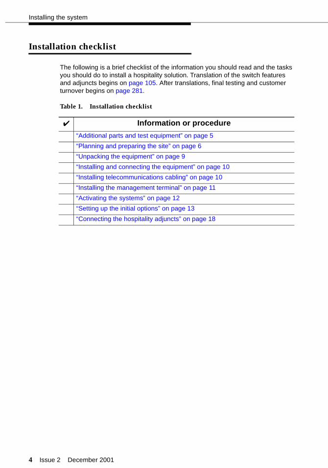
The following is a brief checklist of the information you should read and the tasks you should do to install a hospitality solution. Translation of the switch features and adjuncts begins on page 105. After translations, final testing and customer turnover begins on page 281.
Table 1. Installation checklist
✔ Information or procedure
“Additional parts and test equipment” on page 5
“Planning and preparing the site” on page 6
“Unpacking the equipment” on page 9
“Installing and connecting the equipment” on page 10
“Installing telecommunications cabling” on page 10
“Installing the management terminal” on page 11
“Activating the systems” on page 12
“Setting up the initial options” on page 13
“Connecting the hospitality adjuncts” on page 18
Issue 2 December 2001 5
Additional parts and test equipment
Additional parts and test equipment
Other than the tools and test equipment noted in the installation manuals, you should also have the following items available on site:
■ RS232 mini-tester (comcode 407515139)
NOTE:The mini-tester shows positive voltage with a green LED and negative voltage with a red LED. This can be verified by connecting the mini-tester to a printer’s EIA port, adding power to the printer, and then putting the printer on-line. The Data Terminal Ready (DTR) lamp should then light with a positive (green) voltage. You may already have your own mini-tester that shows positive voltage as red and negative voltage as green. If this is true at your installation, the mini-tester result diagrams shown in this handbook must be read from an “opposite” perspective; that is, if the book shows that DTR should be green, and you have a mini-tester that operates in an “opposite” mode, your mini-tester will show DTR being red. This change in perspective should be true for all data leads.
! CAUTION:After using a mini-tester to check data leads, you MUST remove the mini-tester from the connection. DO NOT leave the mini-tester in-line during actual operation.
■ RS232 gender changers and M25A or M25B RS232 cables
■ Analog line used to place test calls.
See “Appendix A — Parts list” on page 286 for a list of the parts used for this installation. Part numbers are provided in case replacements must be ordered.
6 Issue 2 December 2001
Installing the system
Planning and preparing the site
See Chapter 1 in the DEFINITY ECS and INTUITY installation documents for more information about the tasks in this section.
1. Inventory the equipment delivered to the customer site and verify that it matches the customer’s order. If the equipment does not match the customer’s order, follow the appropriate claims process or report the discrepancies to your Avaya representative. If this is a dealer-installed site, report the discrepancies to the dealer.
The equipment may include the following:
■ Switch cabinets and circuit packs
■ Default translation card for R9.5 and earlier systems (Category B systems only)
Unless instructed otherwise, always use the default translation card for R9.5 and earlier systems.
For R10 and later systems, a license file is provided that defines the customer’s purchased options. For more information about License Files, see the DEFINITY ECS Administrator’s Guide.
■ Avaya Site Administration software (provided for the customer’s PC), or a 715 management terminal
■ Multi-Application Platform (MAP) for INTUITY Lodging Voice Messaging, INTUITY AUDIX Voice Messaging, and INTUITY Lodging Call Accounting
When using the INTUITY Lodging Call Accounting from Homisco, share “Appendix D — Homisco call record format” on page 292 with the PMS vendor before or during the switch integration.
■ InnOvation InnLine 2020 voice messaging systems
Contact your InnOvation representative for installation and setup support.
■ Xiox call accounting equipment, which will be software, a buffer box, and a PC
Call Xiox technical support if any issues arise about their call accounting equipment or installation support. See “Technical support contacts” on page xx.
■ Attendant console
■ Multiappearance telephones (usually the 6400-series or 8400-series; a 6424 or 8434 is recommended as the primary attendant backup telephone)
Issue 2 December 2001 7
Planning and preparing the site
■ Guest room telephones
If custom room telephones and faceplates are being ordered, coordinate the translations on the switch with any special feature access buttons being programmed by the vendor. If programming is done ahead of time, this could save time at installation.
■ Modems
■ Printers
The Okidata® Models 320, 321, and 184T are often used for hospitality installations, but be aware that other printers may be delivered on site.
■ Miscellaneous equipment.
■ If the INTUITY Lodging Call Accounting co-resident application from Homisco has been ordered, part of the miscellaneous equipment is a set of adapters, cables, and user documentation used with the INTUITY system. This equipment is packaged in a separate box with the INTUITY equipment and is labeled “Hold for Homisco Technicians - Do Not Discard!” Save this equipment for the Homisco technicians.
2. Locate the equipment room and lay out the equipment room floor plan. If possible, use standard floor plans as described in DEFINITY ECS System Description. When laying out the equipment locations, consider the following:
■ The switch-to-voice messaging link distance limitations depend on whether you are using Transmission Control Protocol/Internet Protocol (TCP/IP), X.25, or Mode Code:
— The TCP/IP link using the crossover cord is 328 feet (100 meters). This is the default configuration. This is one connectivity method allowed with using the InnLine 2020 system.
— The TCP/IP link using a 10/100base-T auto-sensing hub or router is 656 feet (200 meters). This can be 328 feet (100 meters) on either side of the hub or router. This is one connectivity method allowed with using the InnLine 2020 system.
8 Issue 2 December 2001
Installing the system
— The Isolating Data Interface (IDI) X.25 link must be 200 feet (61 meters) or less. This link is used only on an upgraded system if TCP/IP is not used. Duplicated si systems must use data modules instead of IDI, so the distance limit is not an issue.
— The Mode Code link is done over the same analog voice ports connected between the switch and the voice messaging adjunct. The analog ports have a distance limit of 20000 feet (6100 meters). This connection is limited to upgraded systems; the default configuration is TCP/IP.
■ The link between the switch and the INTUITY Lodging Call Accounting on the MAP is limited to 50 feet (15.2 meters) unless you use DCP data modules to extend the distance. When using a stand-alone call accounting system, there is still the 50 foot (15.2 meter) limit that can be extended with DCP data modules.
■ For the call accounting link, the MAP hardware must be within 50 feet (15.2 meters) of the PMS. This distance can be extended using a pair of Digital Communications Protocol (DCP) data modules connected through the switch.
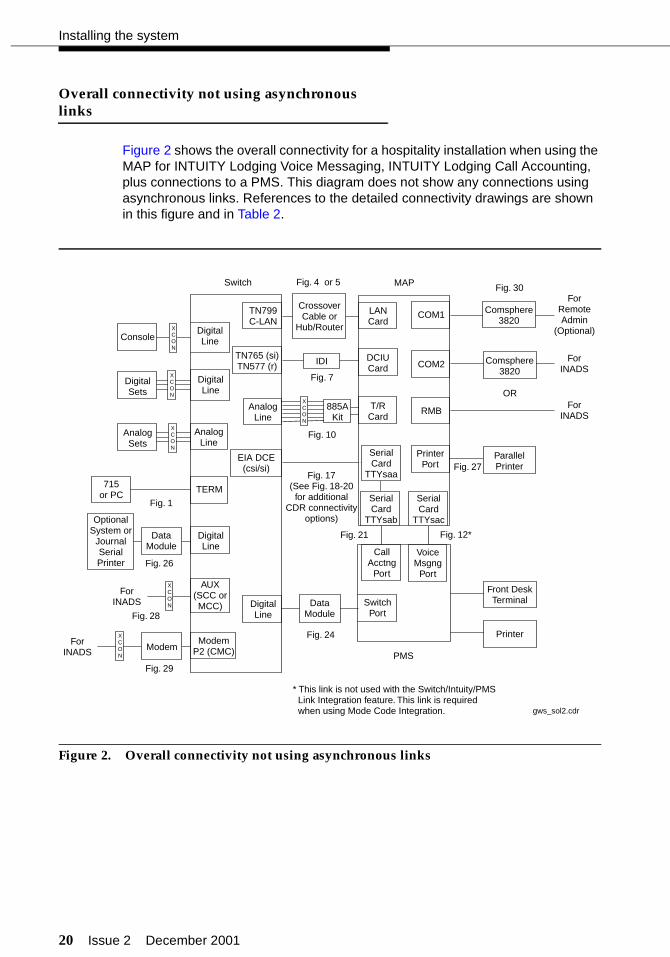
Figure 2 on page 20 and Figure 3 on page 22 illustrate an overall view of connectivity for hospitality solutions.
Additional equipment that you must consider when laying out the floor plan includes the following:
■ A customer-provided PC equipped with Avaya Site Administration, or a 715 management terminal
■ Cross-connect fields
■ Space requirements and room layout
■ Cable slack manager.
3. Lay out and ensure appropriate power for the switch and the management terminal in the equipment room, and arrange for an electrician to install.
4. Lay out and ensure appropriate grounding in the equipment room, including provisions for a coupled bonding conductor (CBC).
5. Determine the location of equipment closets where feeder cables can be terminated.
6. Determine where external trunk lines come into the building and where external trunk converters and adapters will be installed.
7. Determine an appropriate available port circuit on the switch for each telephone, trunk, and peripheral connection needed, and create a provisioning plan based on standard procedures.

Issue 2 December 2001 9
Unpacking the equipment
8. Have the customer contact the PMS vendor and, if not using the INTUITY Lodging Call Accounting, the call accounting system vendor to find out if there are any special connections required to interface with their equipment. It is highly recommended that the customer schedule the vendors to be on-site when the connections are made and the testing is done for the PMS and the call accounting. If the vendors cannot be on-site, they should at least be available by telephone.
9. If this is an upgrade from an existing system, remind the customer that during the cutover, all Automatic Wakeup requests and Do Not Disturb requests must be noted manually. After the cutover is complete, the customer must manually input these requests.
Unpacking the equipment
! CAUTION:Lifting and moving the switch cabinets may require two people. The average weight of a CMC is 50 pounds (23 kilograms); an SCC is 125 pounds (60 kilograms); and the MCC is 800 pounds (268 kilograms). Use caution to avoid injury.
See the appropriate installation document for information about unpacking the equipment:
■ For CMC installations, see Chapter 1 of DEFINITY ECS Installation, Upgrades and Additions for Compact Modular Cabinets.
■ For SCC installations, see the DEFINITY Made Easy Tools.
■ For MCC installations, see the DEFINITY Made Easy Tools.
■ For installations with an INTUITY system, see Chapter 2 in the INTUITY installation documents.
10 Issue 2 December 2001
Installing the system
Installing and connecting the equipment
See the appropriate installation document for information about installing and connecting the equipment:
■ For CMC installations, see Chapter 1 of DEFINITY ECS Installation, Upgrades and Additions for Compact Modular Cabinets.
■ For SCC installations, see the DEFINITY Made Easy Tools.
■ For MCC installations, see the DEFINITY Made Easy Tools.
■ For installations with an INTUITY system, see Chapters 2 through 4 in the INTUITY installation documents.
Installing telecommunications cabling
See the appropriate installation document for information about installing telecommunications cabling:
■ For CMC installations, see Chapter 1 of DEFINITY ECS Installation, Upgrades and Additions for Compact Modular Cabinets.
■ For SCC installations, see the DEFINITY Made Easy Tools.
■ For MCC installations, see the DEFINITY Made Easy Tools.
Issue 2 December 2001 11
Installing the management terminal
Installing the management terminal
The management terminal for administration on either the switch or the INTUITY system can be either a customer-provided PC loaded with the Avaya Site Administration software, or a dedicated management terminal, which must be purchased separately. It is the customer’s responsibility to set up his or her PC with Avaya Site Administration, but the technicians are responsible for connecting and setting up the 715 management terminal if it was purchased for the system. Use the customer’s PC, your own laptop PC, or the management terminal to access the switch for administration during the installation.
See the appropriate installation document for information about installing the management terminal:
■ For CMC installations, see Chapter 1 of DEFINITY ECS Installation, Upgrades and Additions for Compact Modular Cabinets.
■ For SCC installations, see the DEFINITY Made Easy Tools.
■ For MCC installations, see the DEFINITY Made Easy Tools.
■ For installations with an INTUITY system, see Chapter 4 in the INTUITY installation documents.
The following section shows how to connect a PC to the switch.
Connecting a PC to the switch
Use the on-line help for Avaya Site Administration to set the communication options on the PC.
Parts list
■ PC with keyboard and monitor
■ One M25A or M25B RS232 cable (or equivalent 25-pin straight-through cable); see “Appendix A — Parts list” on page 286.
■ One 9-pin to 25-pin transition cable (if using a 9-pin COM port) (comcode 847106945)
■ Gender changers, as needed.
12 Issue 2 December 2001
Installing the system
Cabling diagram
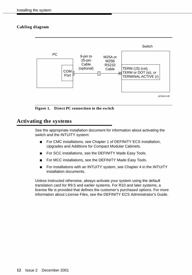
Figure 1. Direct PC connection to the switch
Activating the systems
See the appropriate installation document for information about activating the switch and the INTUITY system:
■ For CMC installations, see Chapter 1 of DEFINITY ECS Installation, Upgrades and Additions for Compact Modular Cabinets.
■ For SCC installations, see the DEFINITY Made Easy Tools.
■ For MCC installations, see the DEFINITY Made Easy Tools.
■ For installations with an INTUITY system, see Chapter 4 in the INTUITY installation documents.
Unless instructed otherwise, always activate your system using the default translation card for R9.5 and earlier systems. For R10 and later systems, a license file is provided that defines the customer’s purchased options. For more information about License Files, see the DEFINITY ECS Administrator’s Guide.
TERM (J3) (csi),TERM or DOT (si), orTERMINAL ACTIVE (r)
Switch
PCM25A orM25BRS232Cable
9-pin to25-pinCable
(optional)COMPort »
pc2serv.cdr
Issue 2 December 2001 13
Setting up the initial options
Setting up the initial options
After activating the systems, there are some initial administration options you must set up. In addition to the procedures given in this section, see the appropriate installation document for information about setting up the initial options:
■ For CMC installations, see Chapter 1 of DEFINITY ECS Installation, Upgrades and Additions for Compact Modular Cabinets.
■ For SCC installations, see the DEFINITY Made Easy Tools.
■ For MCC installations, see the DEFINITY Made Easy Tools.
■ For installations with an INTUITY system, see Chapter 5 in the INTUITY installation documents.
NOTE:Before setting any options, ensure that the default translation card is being used on a Category B switch for R9.5 and earlier. For R10 and later systems, a license file is provided that defines the customer’s purchased options. For more information about License Files, see the DEFINITY ECS Administrator’s Guide.
14 Issue 2 December 2001
Installing the system
To set up the initial options:
1. After the switch powers up, log on to the switch using the craft login ID and the crftpw password. Distributors should use the dadmin login ID.
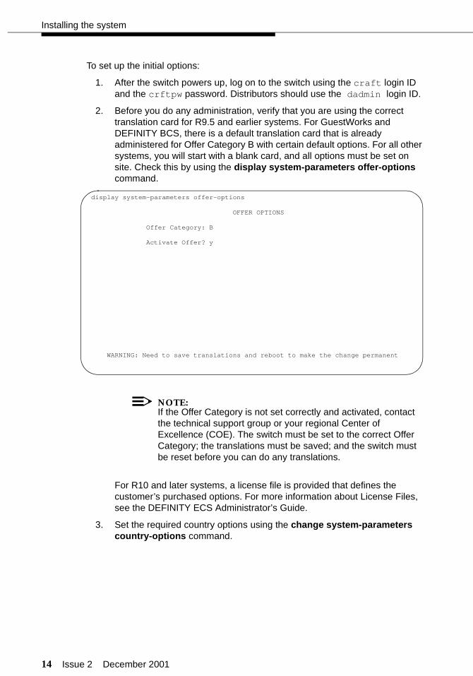
2. Before you do any administration, verify that you are using the correct translation card for R9.5 and earlier systems. For GuestWorks and DEFINITY BCS, there is a default translation card that is already administered for Offer Category B with certain default options. For all other systems, you will start with a blank card, and all options must be set on site. Check this by using the display system-parameters offer-options command.
NOTE:If the Offer Category is not set correctly and activated, contact the technical support group or your regional Center of Excellence (COE). The switch must be set to the correct Offer Category; the translations must be saved; and the switch must be reset before you can do any translations.
For R10 and later systems, a license file is provided that defines the customer’s purchased options. For more information about License Files, see the DEFINITY ECS Administrator’s Guide.
3. Set the required country options using the change system-parameters country-options command.
display system-parameters offer-options
OFFER OPTIONS
Offer Category: B
Activate Offer? y
WARNING: Need to save translations and reboot to make the change permanent
Issue 2 December 2001 15
Setting up the initial options
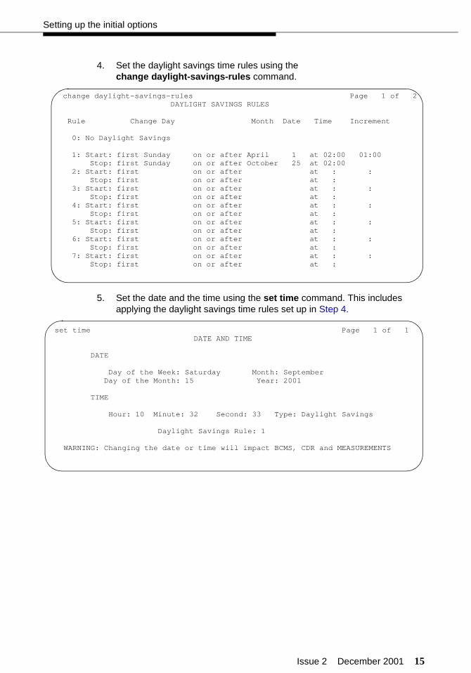
4. Set the daylight savings time rules using the change daylight-savings-rules command.
5. Set the date and the time using the set time command. This includes applying the daylight savings time rules set up in Step 4.
change daylight-savings-rules Page 1 of 2 DAYLIGHT SAVINGS RULES
Rule Change Day Month Date Time Increment
0: No Daylight Savings
1: Start: first Sunday on or after April 1 at 02:00 01:00 Stop: first Sunday on or after October 25 at 02:00 2: Start: first on or after at : : Stop: first on or after at : 3: Start: first on or after at : : Stop: first on or after at : 4: Start: first on or after at : : Stop: first on or after at : 5: Start: first on or after at : : Stop: first on or after at : 6: Start: first on or after at : : Stop: first on or after at : 7: Start: first on or after at : : Stop: first on or after at :
set time Page 1 of 1 DATE AND TIME
DATE
Day of the Week: Saturday Month: September Day of the Month: 15 Year: 2001
TIME
Hour: 10 Minute: 32 Second: 33 Type: Daylight Savings
Daylight Savings Rule: 1
WARNING: Changing the date or time will impact BCMS, CDR and MEASUREMENTS

16 Issue 2 December 2001
Installing the system
6. If the switch has EPNs in different time zone locations, use the change location command to set the time zone offset, daylight savings rules, and numbering plan area code.
7. Set the switch maintenance parameters using the change system-parameters maintenance command. For csi systems that have a C-LAN (TN799) circuit pack, use Page 2 of this screen to verify that the Bus Bridge Packet Interface 2 has been enabled for the C-LAN circuit pack. If it is not already assigned, enter the C-LAN circuit pack equipment location, and use the defaults for the Timeslot Port fields as shown below.
change locations Page 1 of 1 LOCATIONS
ARS Prefix 1 Required For 10-Digit NANP Calls? n
Number Name Timezone Daylight-Savings Number Plan Offset Rule Area Code 1 Main + 00:00 1 303
change system-parameters maintenance Page 2 of 3 MAINTENANCE-RELATED SYSTEM PARAMETERS
MINIMUM MAINTENANCE THRESHOLDS ( Before Notification ) TTRs: 16 CPTRs: 16 Call Classifier Ports: 16 MMIs: 0 VCs: 0
TERMINATING TRUNK TRANSMISSION TEST ( Extension ) Test Type 100: Test Type 102: Test Type 105:
ISDN MAINTENANCE ISDN-PRI Test Call Extension: ISDN-BRI Service SPID:
DS1 MAINTENANCE DS0 Loop-Around Test Call Extension:
SPE OPTIONAL BOARDS Packet Intf1? y Packet Intf2? y Bus Bridge: 01B07 Inter-Board Link Timeslots Pt0: 6 Pt1: 1 Pt2: 1
Issue 2 December 2001 17
Setting up the initial options
8. Verify that the hospitality customer options have been enabled by checking the display system-parameters customer-options screen. On Page 3, the following options must be enabled:
■ Hospitality (Basic)
■ Hospitality (G3V3 Enhancements)
These options can be enabled only with a superuser login ID. Contact technical support or your COE if you do not have permission to make this change.
9. Change the craft password using the change password craft command.
! CAUTION:After the craft password is changed, the new password must be safeguarded to prevent unauthorized administration changes. This password MUST NOT BE REVEALED to the customer.
10. Save these initial translations. Use the save translation command. Label the translation card with the current date and switch name.
! CAUTION:It is recommended that you save your translations regularly during the installation process. If a power failure occurs, all translations since the last save are lost and must be readministered.
18 Issue 2 December 2001
Installing the system
Connecting the hospitality adjuncts
The hospitality adjuncts include the following:
■ INTUITY Lodging Voice Messaging
INTUITY Lodging Voice Messaging is an optional adjunct that resides on the MAP. INTUITY Lodging is used for the guest access to voice messages; and INTUITY AUDIX is used for the office staff to access voice messaging.
■ INTUITY Lodging Call Accounting
INTUITY Lodging Call Accounting is a co-resident application from Homisco that resides on the MAP. It is based on a product from the Homisco Corporation. At most installations, you can expect a technician from Homisco to be on site to install the software and hardware for the call accounting portion of the product. The Homisco technician will assist you in making the call accounting system interface to the switch.
For installations that include INTUITY Lodging Voice Messaging and INTUITY Lodging Call Accounting, all connections are shown in complete detail.
■ InnOvation InnLine 2020 voice messaging
The InnLine 2020 is a hospitality-industry voice messaging system that integrates with the switch using TCP/IP over a LAN to the C-LAN circuit pack. Installation support is provided by InnOvation.
■ Stand-Alone call accounting
Stand-alone call accounting systems (such as Xiox) can be installed if the call record format is compatible with the switch. Two typical formats are printer and Teleseer.
For installations that include voice mail or call accounting from another vendor, the connections are shown up to a definable demarcation point. Connections beyond that demarcation point must be coordinated with the vendor.
Issue 2 December 2001 19
Connecting the hospitality adjuncts
■ Property Management System (PMS)
The PMS is a vendor-provided product that interfaces to the switch according to the GuestWorks and DEFINITY ECS Property Management System Interface Specifications. If the PMS follows those specifications, the PMS will interface to the switch when properly connected to the switch. The PMS connections are shown up to a definable demarcation point. Connections beyond that demarcation point must be coordinated with the vendor.
■ Printers
Two serial printers can be installed to print hospitality reports and to keep a log of events as they occur on the switch. Each printer connects to the switch using a terminal server or a DCP data module. The printers are designated as either a “journal/schedule” printer or a “log” printer. The journal/schedule printer records Emergency Access to Attendant calls and Automatic Wakeup calls. The log printer records housekeeping updates when the PMS link is down, in addition to recording any other PMS-related events. These PMS events are shown in “Appendix C — List PMS down events” on page 289.
NOTE:In most cases, only one printer is provided to perform both the journal/schedule and log printer functions.
A parallel printer may be connected to the INTUITY system to run call accounting reports or reports from the INTUITY messaging system.
20 Issue 2 December 2001
Installing the system
Overall connectivity not using asynchronous links
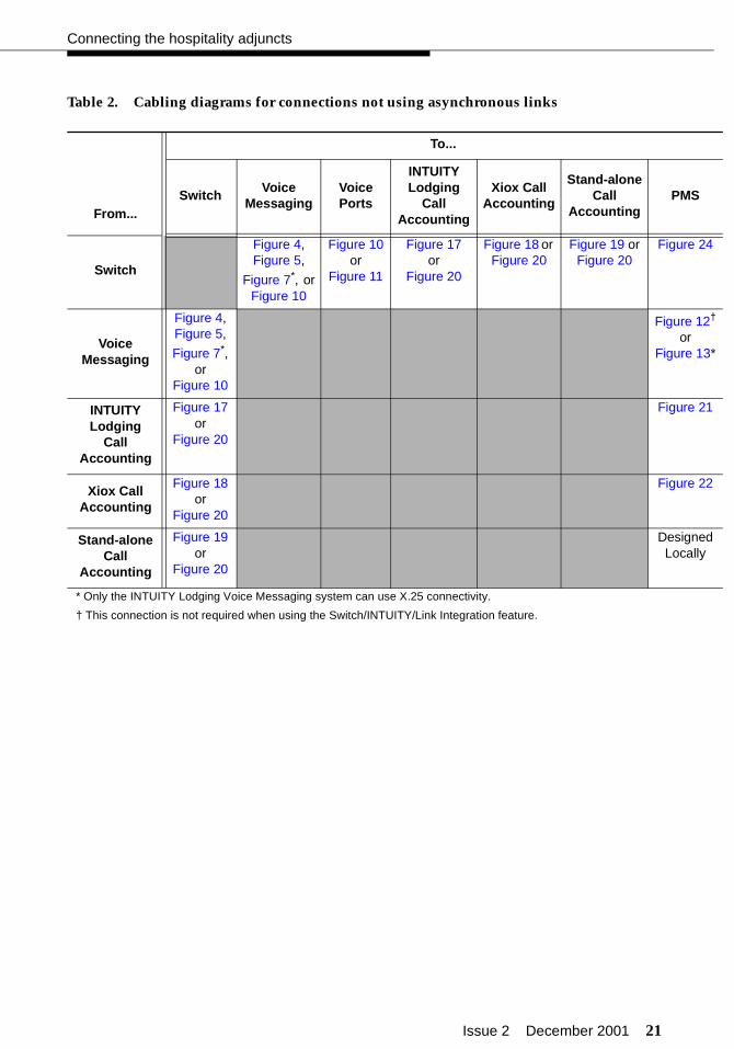
Figure 2 shows the overall connectivity for a hospitality installation when using the MAP for INTUITY Lodging Voice Messaging, INTUITY Lodging Call Accounting, plus connections to a PMS. This diagram does not show any connections using asynchronous links. References to the detailed connectivity drawings are shown in this figure and in Table 2.
Figure 2. Overall connectivity not using asynchronous links
Console
OptionalSystem or
JournalSerialPrinter
DigitalSets
AnalogSets
TN765 (si)TN577 (r)
LANCard
TN799C-LAN
EIA DCE(csi/si)
AnalogLine
AnalogLine
DigitalLine
DigitalLine
DigitalLine
ModemP2 (CMC)
DigitalLine
AUX(SCC orMCC)
Switch
DCIUCard
COM1
T/RCard
COM2
RMB
PrinterPort
MAP
OR
Fig. 7
Fig. 4 or 5
Fig. 10
Fig. 17(See Fig. 18-20
for additionalCDR connectivity
options)
Fig. 26
Fig. 29
Fig. 21 Fig. 12*
Fig. 27
* This link is not used with the Switch/Intuity/PMSLink Integration feature. This link is requiredwhen using Mode Code Integration.
Fig. 30
Fig. 28
IDI
CrossoverCable or
Hub/Router
Comsphere3820
Comsphere3820
ParallelPrinter
Printer
Front DeskTerminal
ForRemoteAdmin
(Optional)
ForINADS
ForINADS
ForINADS
ForINADS
885AKit
XCON
715or PC
TERM
Fig. 1
DataModule
Modem
DataModule
PMS
SwitchPort
VoiceMsgng
Port
CallAcctng
PortXCON
XCON
SerialCard
TTYsaa
SerialCard
TTYsab
SerialCard
TTYsac
XCON
XCON
XCON
gws_sol2.cdr
Fig. 24
Issue 2 December 2001 21
Connecting the hospitality adjuncts
Table 2. Cabling diagrams for connections not using asynchronous links
From...
To...
SwitchVoice
MessagingVoice Ports
INTUITY Lodging
Call Accounting
Xiox Call Accounting
Stand-alone Call
AccountingPMS
Switch
Figure 4,Figure 5,
Figure 7*, orFigure 10
* Only the INTUITY Lodging Voice Messaging system can use X.25 connectivity.
Figure 10or
Figure 11
Figure 17 or
Figure 20
Figure 18 or Figure 20
Figure 19 orFigure 20
Figure 24
VoiceMessaging
Figure 4,Figure 5,
Figure 7*, or
Figure 10
Figure 12† or
Figure 13*
† This connection is not required when using the Switch/INTUITY/Link Integration feature.
INTUITY Lodging
Call Accounting
Figure 17 or
Figure 20
Figure 21
Xiox Call Accounting
Figure 18or
Figure 20
Figure 22
Stand-alone Call
Accounting
Figure 19 or
Figure 20
Designed Locally

22 Issue 2 December 2001
Installing the system
Overall connectivity using asynchronous links
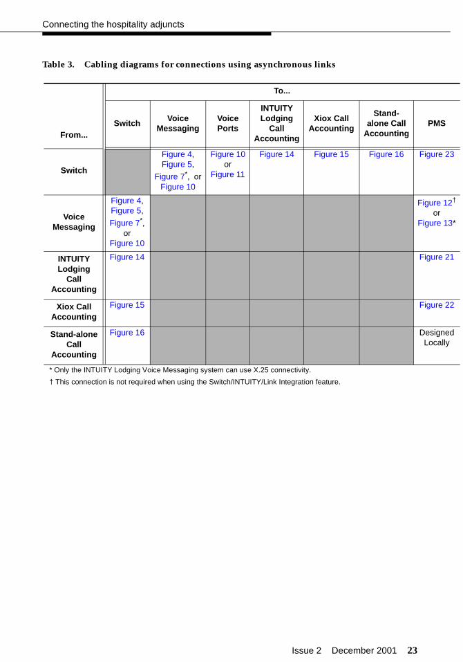
Figure 3 shows the overall connectivity for a hospitality installation when using the MAP for INTUITY Lodging Voice Messaging, INTUITY Lodging Call Accounting, plus connections to a PMS. This diagram shows connections using asynchronous links. References to the detailed connectivity drawings are shown in this figure and in Table 3.
Figure 3. Overall connectivity using asynchronous links
Console
OptionalSystem or
JournalSerialPrinter
DigitalSets
AnalogSets
TN765 (si)TN577 (r)
LANCard
TN799C-LAN
AnalogLine
AnalogLine
DigitalLine
DigitalLine
ModemP2 (CMC)
AUX(SCC orMCC)
Switch
DCIUCard
COM1
T/RCard
COM2
RMB
PrinterPort
MAP
OR
Fig. 7
Fig. 4 or 5
Fig. 10
Fig. 25
Fig. 29
Fig. 21 Fig. 12*
Fig. 27
* This link is not used withthe Switch/Intuity/PMS LinkIntegration feature. This linkis required when using ModeCode Integration.
Fig. 30
Fig. 28
IDI
CrossoverCable or
Hub/Router
Comsphere3820
Comsphere3820
ParallelPrinter
Printer
Front DeskTerminal
ForRemoteAdmin
(Optional)
ForINADS
ForINADS
ForINADS
ForINADS
885AKit
XCON
715or PC
TERM
Fig. 1
Modem
Terminalserver
PMS
SwitchPort
VoiceMsgng
Port
CallAcctng
Port
XCON
XCON
SerialCard
TTYsaa
SerialCard
TTYsab
SerialCard
TTYsac
XCON
XCON
XCON
conn_w_links.cdr
Fig. 23
TN799C-LAN
HubFig. 14
Issue 2 December 2001 23
Connecting the hospitality adjuncts
Table 3. Cabling diagrams for connections using asynchronous links
From...
To...
SwitchVoice
MessagingVoice Ports
INTUITY Lodging
Call Accounting
Xiox Call Accounting
Stand-alone Call
AccountingPMS
Switch
Figure 4,Figure 5,
Figure 7*, orFigure 10
* Only the INTUITY Lodging Voice Messaging system can use X.25 connectivity.
Figure 10 or
Figure 11
Figure 14 Figure 15 Figure 16 Figure 23
VoiceMessaging
Figure 4,Figure 5,
Figure 7*, or
Figure 10
Figure 12† or
Figure 13*
† This connection is not required when using the Switch/INTUITY/Link Integration feature.
INTUITY Lodging
Call Accounting
Figure 14 Figure 21
Xiox Call Accounting
Figure 15 Figure 22
Stand-alone Call
Accounting
Figure 16 Designed Locally

24 Issue 2 December 2001
Installing the system
In Figure 2 and in Figure 3, there are a variety of digital line circuit packs and telephones/data modules that can be used. Table 4 shows which circuit packs should be used to support the different digital telephones and data modules.
Table 4. Digital Line Circuit Packs and Telephone Equipment Compatibility
Equipment
Circuit Packs
TN754(4-wire)
TN2181(2-wire)
TN2214(2-wire)
TN2224(2-wire)
302D Console (2-wire) No Yes Yes Yes
302B/C Console (2-wire/4-wire) Yes Yes Yes Yes
6400-Series telephones (2-wire) No Yes Yes Yes
8400-Series telephones/data modules (2-wire/4-wire)
Yes Yes Yes Yes
7400-Series telephones/data modules (4-wire)
Yes No No No

Issue 2 December 2001 25
Connecting the hospitality adjuncts
Switch-to-voice messaging admin link (TCP/IP)
This data link transfers information to the voice messaging system for office staff voice messaging. For all new installations, this is the recommended way to connect the switch to the voice messaging system for administrative messages. If the system is an upgrade, you may reuse the X.25 hardware for this connection; see “Switch-to-INTUITY admin link (X.25)” on page 29. For installations using Mode Code integration, see “Switch-to-INTUITY admin link (Mode Code integration)” on page 31.
The TCP/IP link can be used for connections to the INTUITY and InnOvation voice messaging systems.
Parts list
■ An ethernet port on the C-LAN circuit pack
■ One IP Media Processor adapter (comcode 848525887) for a 100 Mbps link (TN799DP or later), or
UTP Category 5 cross-connect hardware and connecting blocks, or
One 259A adapter (comcode 102631413) for a 10 Mbps link (TN799C or earlier)
■ One 10/100Base-T auto-sensing LAN hub or customer router (required when using asynchronous links), or
One 6-inch RJ45 crossover cord (comcode 846943306 or 104154414) for a single 10 Mbps link
■ One or two RJ45 UTP Category 5 modular cords (see “Appendix A — Parts list” on page 286)
■ One or more 451A in-line RJ45 adapters, as needed (used to connect modular cords together)
■ One LAN card on the MAP (for INTUITY R4.4, model 8412; for INTUITY R5 and later, model 8416), or
One network card on the InnLine 2020 system
26 Issue 2 December 2001
Installing the system
Distance limits
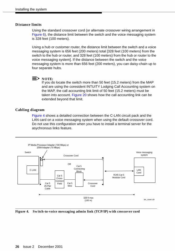
Using the standard crossover cord (or alternate crossover wiring arrangement in Figure 6), the distance limit between the switch and the voice messaging system is 328 feet (100 meters).
Using a hub or customer router, the distance limit between the switch and a voice messaging system is 656 feet (200 meters) total [328 feet (100 meters) from the switch to the hub or router, and 328 feet (100 meters) from the hub or router to the voice messaging system]. If the distance between the switch and the voice messaging system is more than 656 feet (200 meters), you can daisy-chain up to four separate hubs.
NOTE:If you do locate the switch more than 50 feet (15.2 meters) from the MAP and are using the coresident INTUITY Lodging Call Accounting system on the MAP, the call accounting link limit of 50 feet (15.2 meters) must be taken into account. Figure 20 shows how the call accounting link can be extended beyond that limit.
Cabling diagram
Figure 4 shows a detailed connection between the C-LAN circuit pack and the LAN card on a voice messaging system when using the default crossover cord. Do not use this configuration when you have to install a terminal server for the asychronous links feature.
Figure 4. Switch-to-voice messaging admin link (TCP/IP) with crossover cord
C-LAN
Switch
328 ft max(100 m)
LANCard
Voice messagingsystem
ORCat 5
ConnectingBlock
Cat 5Cross-
ConnectField
Crossover Cord
CrossoverCord
Cat 525-PairCable
Cat 5Wire
RJ45 Cat 5Modular Cord
IP Media Processor Adapter (100 Mbps) or259A Adapter (10 Mbps)
lan_xover.cdr

Issue 2 December 2001 27
Connecting the hospitality adjuncts
Figure 5 shows a detailed connection between the C-LAN circuit pack and the LAN card on a voice messaging system when using a hub or customer router. Use this connection when you have to install a terminal server for the asynchronous links feature.
Figure 5. Switch-to-voice messaging admin link (TCP/IP) with hub or router
The C-LAN circuit pack ethernet lead designations are as follows:
Use this information when making connections from the using an IP Media Processor adapter, a 259A adapter, or standard cross-connect wiring.
Lead name
25-pair cable wire color
25-pair cable
connector pin-out
RJ45 jack
pin-out
Terminal block pin-out on
connecting block
TD+ white/orange 27 1 3
TD- orange/white 2 2 4
RD+ white/green 28 3 5
RD- green/white 3 6 6
C-LAN
Switch
Hub orRouter
328 ft max(100 m)
328 ft max(100 m)
AC Power
LANCard
Voice messagingsystem
ORCat 5
ConnectingBlock
Cat 5Cross-
ConnectField
RJ45 Cat 5Modular Cord
RJ45 Cat 5Modular Cord
RJ45 Cat 5Modular Cord
Cat 525-PairCable
Cat 5Wire
lan_ded.cdr
IP Media Processor Adapter (100 Mbps) or259A Adapter (10 Mbps)
28 Issue 2 December 2001
Installing the system
Crossover wiring
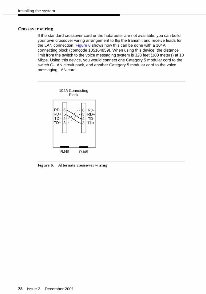
If the standard crossover cord or the hub/router are not available, you can build your own crossover wiring arrangement to flip the transmit and receive leads for the LAN connection. Figure 6 shows how this can be done with a 104A connecting block (comcode 105164859). When using this device, the distance limit from the switch to the voice messaging system is 328 feet (100 meters) at 10 Mbps. Using this device, you would connect one Category 5 modular cord to the switch C-LAN circuit pack, and another Category 5 modular cord to the voice messaging LAN card.
Figure 6. Alternate crossover wiring
RJ45 RJ45
6543
6543
RD-RD+TD-TD+
RD-RD+TD-TD+
104A ConnectingBlock
Issue 2 December 2001 29
Connecting the hospitality adjuncts
Switch-to-INTUITY admin link (X.25)
This data link transfers information to support the INTUITY AUDIX service for office staff voice messaging. This connection will be used only if:
■ Your system has been upgraded from an earlier system, and
■ The customer chooses to retain their X.25 hardware (a PI circuit pack is needed on the si system, or a Packet Gateway circuit pack is needed on an r system) instead of the TCP/IP C-LAN hardware.
See “Switch-to-voice messaging admin link (TCP/IP)” on page 25. For installations using Mode Code integration, see “Switch-to-INTUITY admin link (Mode Code integration)” on page 31.
NOTE:The connectivity shown in this section will not work on an si system with duplication. For a duplicated system, the connection between the switch and the INTUITY is done with DCP data modules. See your project manager for more information.
Parts list
■ A PI port (TN765) on an si system, or a Packet Gateway port (TN577) on an r system
■ One H600-347 cable (r system only)
■ One H600-210 Group 3 cable (50 feet; 15.2 meters)
■ One 105C IDI (comcode 107422735) or 105D IDI (comcode 108367376)
An IDI provides electrical isolation and protection between the switch and the INTUITY hardware. The dip switch settings on the IDI must be set for “Direct Connect.”
■ One ED1E434-11 Group 175 cable (4.5 feet; 1.5 meters)
■ One DCIU card (comcode 406801647, J1P260AA, L31) installed in the MAP, usually located in slot 1.
30 Issue 2 December 2001
Installing the system
Distance limits
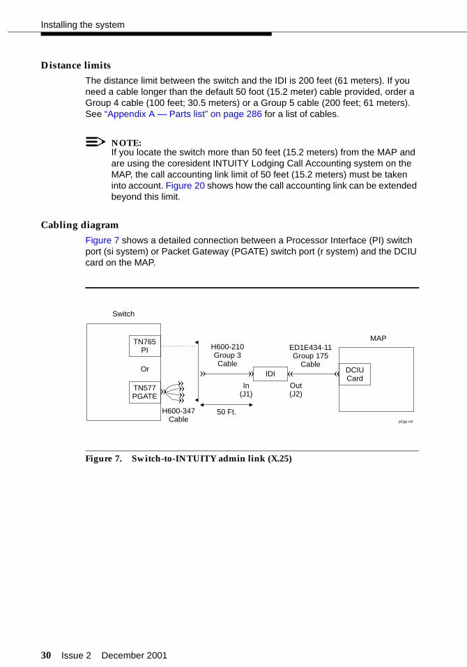
The distance limit between the switch and the IDI is 200 feet (61 meters). If you need a cable longer than the default 50 foot (15.2 meter) cable provided, order a Group 4 cable (100 feet; 30.5 meters) or a Group 5 cable (200 feet; 61 meters). See “Appendix A — Parts list” on page 286 for a list of cables.
NOTE:If you locate the switch more than 50 feet (15.2 meters) from the MAP and are using the coresident INTUITY Lodging Call Accounting system on the MAP, the call accounting link limit of 50 feet (15.2 meters) must be taken into account. Figure 20 shows how the call accounting link can be extended beyond this limit.
Cabling diagram
Figure 7 shows a detailed connection between a Processor Interface (PI) switch port (si system) or Packet Gateway (PGATE) switch port (r system) and the DCIU card on the MAP.
Figure 7. Switch-to-INTUITY admin link (X.25)
TN765PI
TN577PGATE
DCIUCard
Switch
MAP
In(J1)
Or
Out(J2)
50 Ft.
ED1E434-11Group 175
Cable
H600-210Group 3Cable
H600-347Cable
««
«
«
«
««««
IDI
pi2gp.cdr

Issue 2 December 2001 31
Connecting the hospitality adjuncts
Switch-to-INTUITY admin link (Mode Codeintegration)
When using Mode Code Integration, the administrative link between the switch and the voice messaging system (the link that transfers information to support the service for office staff voice messaging) connects by way of an analog port on the switch and a voice port on the voice messaging system. This connection is the same as the voice port connections shown in “Switch-to-INTUITY voice port connections” on page 32 and in Figure 10.
In other words, the voice ports used for leaving and retrieving messages on the voice messaging system are the same voice ports used for Mode Code Integration. This means that the ports will be in use for the amount of time it takes to leave a message, plus the amount of time it takes for the Mode Codes to exchange messages between the switch and voice messaging system. This will affect the traffic-handling of the voice messaging system.
The Mode Code Integration link can be used for connections to the INTUITY and InnOvation voice messaging systems.
Mode Code Integration should not be used if TCP/IP or X.25 link integration is available. See “Switch-to-voice messaging admin link (TCP/IP)” on page 25 or “Switch-to-INTUITY admin link (X.25)” on page 29 for more information.
NOTE:When using Mode Code Integration, you cannot take advantage of the Switch/INTUITY/PMS Link Integration feature. This means that you must install the link shown in “INTUITY Lodging-to-PMS link” on page 39.
Mode Code Integration between the switch and the MAP is described in more detail in the following documents:
■ DEFINITY ECS Administrator’s Guide
■ INTUITY Messaging Solutions Release 4 MAP/5P System Installation
■ INTUITY Messaging Solutions Integration with System 75, DEFINITY Generics 1 & 3, and R5/6
■ INTUITY Messaging Solutions Release 5 Documentation (CD).
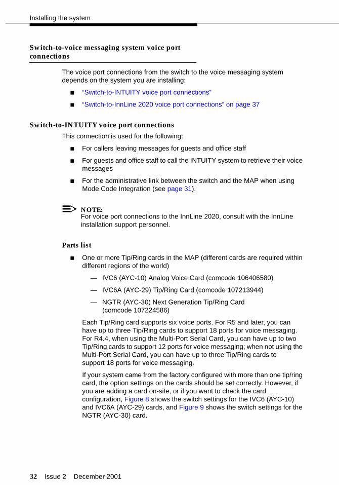
32 Issue 2 December 2001
Installing the system
Switch-to-voice messaging system voice portconnections
The voice port connections from the switch to the voice messaging system depends on the system you are installing:
■ “Switch-to-INTUITY voice port connections”
■ “Switch-to-InnLine 2020 voice port connections” on page 37
Switch-to-INTUITY voice port connections
This connection is used for the following:
■ For callers leaving messages for guests and office staff
■ For guests and office staff to call the INTUITY system to retrieve their voice messages
■ For the administrative link between the switch and the MAP when using Mode Code Integration (see page 31).
NOTE:For voice port connections to the InnLine 2020, consult with the InnLine installation support personnel.
Parts list
■ One or more Tip/Ring cards in the MAP (different cards are required within different regions of the world)
— IVC6 (AYC-10) Analog Voice Card (comcode 106406580)
— IVC6A (AYC-29) Tip/Ring Card (comcode 107213944)
— NGTR (AYC-30) Next Generation Tip/Ring Card (comcode 107224586)
Each Tip/Ring card supports six voice ports. For R5 and later, you can have up to three Tip/Ring cards to support 18 ports for voice messaging. For R4.4, when using the Multi-Port Serial Card, you can have up to two Tip/Ring cards to support 12 ports for voice messaging; when not using the Multi-Port Serial Card, you can have up to three Tip/Ring cards to support 18 ports for voice messaging.
If your system came from the factory configured with more than one tip/ring card, the option settings on the cards should be set correctly. However, if you are adding a card on-site, or if you want to check the card configuration, Figure 8 shows the switch settings for the IVC6 (AYC-10) and IVC6A (AYC-29) cards, and Figure 9 shows the switch settings for the NGTR (AYC-30) card.

Issue 2 December 2001 33
Connecting the hospitality adjuncts
For each voice port card, you must install an 885A connector kit. Figure 10 shows connections for one kit using all six voice ports. Depending on the customer’s order, you will install voice ports in pairs up to 18 ports.
■ Two or more ED5P208-30 Group 16 modular cords
You need two cords for each Tip/Ring card.
■ One 885A connector kit for each Tip/Ring card installed in the MAP (ED-5P907-70, Group 1, comcode 601419666)
These kits come with one 885A connecting block, six RJ11C 4-wire modular cords (comcode 103732582), and two RJ25 6-wire modular cords.
! CAUTION:The two RJ25 6-wire modular cords that come with the 885A connector kits are not used in this application. Do not use the RJ25 cords for any connections; the wiring in the RJ25 cords will not work in this application.
Use the 885A connecting block label to record the extension numbers of the voice ports connected to the MAP.
■ Ferrites (one for each voice line) (comcode 407616846)
Ferrites are required for installation in some countries. See INTUITY Messaging Solution Release 4 Supplement for Technicians for more information.
■ 103A modular connecting blocks (one for each voice port) (comcode 105164818)
■ Standard cross-connect hardware
■ Ports on an analog circuit pack.
Each analog circuit pack supports 8, 16, or 24 analog voice connections. Depending on the circuit pack and the required number of voice ports, you may need to spread out the voice port assignments over more than one circuit pack. For example, if you are using a 16-port circuit pack, use no more than four ports of circuits 1-8 and four ports of circuits 9-16 on that circuit pack. If you still need more INTUITY voice ports, select a circuit pack that is at least one-quarter carrier distance away from the first circuit pack. For example, if your system has 12 voice ports, and you assign the first eight ports to the circuit pack in slot 3, assign the other four voice ports to a circuit pack in slot 7 or higher. See more about circuit pack characteristics in the DEFINITY ECS System Description.
Distance limits
The distance limit from an analog port to the MAP is 20000 feet (6100 meters) using 24 AWG wire.
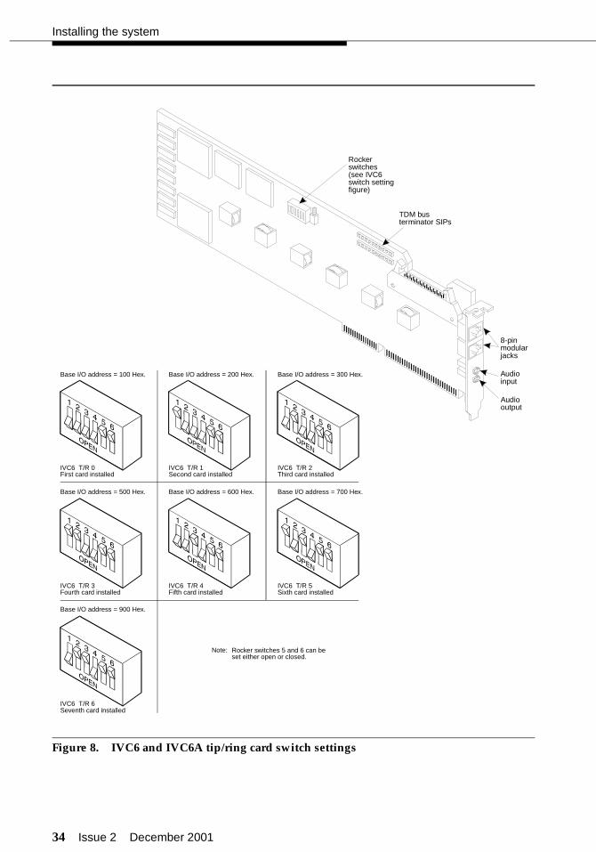
34 Issue 2 December 2001
Installing the system
Figure 8. IVC6 and IVC6A tip/ring card switch settings
8-pinmodularjacks
Audioinput
Audiooutput
TDM busterminator SIPs
Rockerswitches(see IVC6switch settingfigure)
Base I/O address = 100 Hex.
IVC6 T/R 0First card installed
Base I/O address = 200 Hex.
IVC6 T/R 1Second card installed
Base I/O address = 300 Hex.
IVC6 T/R 2Third card installed
Base I/O address = 500 Hex.
IVC6 T/R 3Fourth card installed
Base I/O address = 600 Hex.
IVC6 T/R 4Fifth card installed
Base I/O address = 700 Hex.
IVC6 T/R 5Sixth card installed
Base I/O address = 900 Hex.
IVC6 T/R 6Seventh card installed
Rocker switches 5 and 6 can beset either open or closed.
Note:
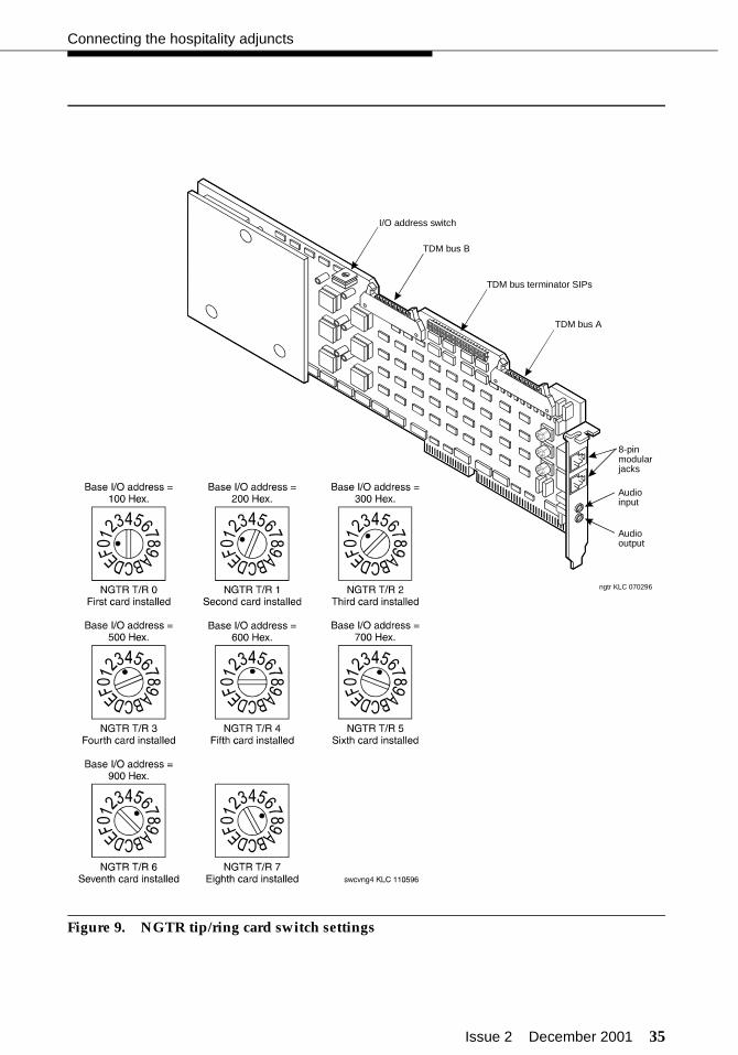
Issue 2 December 2001 35
Connecting the hospitality adjuncts
Figure 9. NGTR tip/ring card switch settings
ngtr KLC 070296
I/O address switch
TDM bus B
TDM bus A
TDM bus terminator SIPs
8-pinmodularjacks
Audiooutput
Audioinput

36 Issue 2 December 2001
Installing the system
Cabling diagram
Figure 10 shows the connections between analog circuit pack ports on the switch and a Tip/Ring card on the MAP.
Figure 10. Switch-to-INTUITY voice port connections
AnalogLine
Switch
Cross-ConnectField
ED5P208-30Group 16
Modular Cords
103AConnecting
Blocks
RJ11C4-Wire
ModularCords
IVP6# 885A ADAPTER
LINES
LINES
1-2-3
4-5-6
LINE 1 LINE 2 LINE 3
LINE 4 LINE 5 LINE 6
EXT: EXT: EXT:
EXT: EXT: EXT:Tip/RingCard
MAP
123
456
AUDIO
IN
OUT
m5_791.cdr
Issue 2 December 2001 37
Connecting the hospitality adjuncts
Switch-to-InnLine 2020 voice port connections
This connection is used for the following:
■ For callers leaving messages for guests and office staff
■ For guests and office staff to call the voice messaging system to retrieve their voice messages
■ For the administrative link between the switch and the voice messaging system when using Mode Code Integration (see page 31).
For detailed voice port connections to the InnLine 2020, see the InnLine 2020 Installation guide that is shipped with the system.
Parts list
■ One or more Tip/Ring cards in the InnLine 2020. Each card supports four voice ports. For each voice port, you must use a locally-provided 2-line adapter.
■ 103A modular connecting blocks (one for each voice port) (comcode 105164818)
■ Standard cross-connect hardware
■ Ports on an analog circuit pack.
Each analog circuit pack supports 8, 16, or 24 analog voice connections. Depending on the circuit pack and the required number of voice ports, you may need to spread out the voice port assignments over more than one circuit pack. For example, if you are using a 16-port circuit pack, use no more than four ports of circuits 1-8 and four ports of circuits 9-16 on that circuit pack. If you still need more voice ports, select a circuit pack that is at least one-quarter carrier distance away from the first circuit pack. For example, if your system has 12 voice ports, and you assign the first eight ports to the circuit pack in slot 3, assign the other four voice ports to a circuit pack in slot 7 or higher. See more about circuit pack characteristics in the DEFINITY ECS System Description.
Distance limits
The distance limit from an analog port to the voice messaging system is 20000 feet (6100 meters) using 24 AWG wire.

38 Issue 2 December 2001
Installing the system
Cabling diagram
Figure 11 shows the connections between analog circuit pack ports on the switch and the voice ports on the InnLine 2020.
Figure 11. Switch-to-InnLine 2020 voice port connections
AnalogLine
Switch
Cross-ConnectField
103AConnecting
BlocksModular Cords
with 2-line adapters
innlinevp.cdr
DemarcationPoint
InnLine 2020

Issue 2 December 2001 39
Connecting the hospitality adjuncts
INTUITY Lodging-to-PMS link
This connection is used to activate and deactivate guest voice messaging mailboxes when guests check-in and check-out.
NOTE:If the Switch/INTUITY/PMS Link Integration feature is used, this connection is not required. See “Voice messaging-to-PMS translations and testing” on page 252 for more information about this feature. If Mode Code Integration is used, this link is required and cannot be removed.
Parts list
■ One Multi-Port Serial card on the MAP (comcode 407009406; J1P260AA1, List 12)
For this connection, use the third port on the card. This port is not marked on the card, but is administered in software as port TTYsac.
■ One D6AP modular cord (comcode 102937604)
■ One Equinox P/N:210068 DTE 10/10 adapter (DB25 DTE, comcode 406983155); see “Appendix B — Connector pinouts”
■ One null modem with transmit/receive swapped (all other leads are straight-through) (comcode 407122043)
■ One RS232 cable (use gender changers as needed).
Distance limits
The distance limit from the MAP to the PMS is 50 feet (15.2 meters).
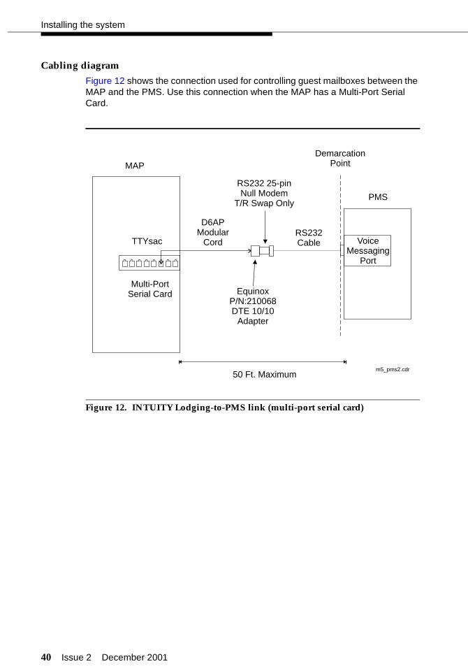
40 Issue 2 December 2001
Installing the system
Cabling diagram
Figure 12 shows the connection used for controlling guest mailboxes between the MAP and the PMS. Use this connection when the MAP has a Multi-Port Serial Card.
Figure 12. INTUITY Lodging-to-PMS link (multi-port serial card)
.MAP
PMS
VoiceMessaging
Port
D6APModular
Cord
RS232 25-pinNull Modem
T/R Swap Only
EquinoxP/N:210068DTE 10/10
Adapter
RS232Cable
DemarcationPoint
Multi-PortSerial Card
TTYsac
50 Ft. Maximumm5_pms2.cdr

Issue 2 December 2001 41
Connecting the hospitality adjuncts
For some installations, the connection used for controlling guest mailboxes between the MAP and the PMS uses COM1 instead of the Multi-Port Serial Card. Figure 13 shows this connection.
Figure 13. INTUITY Lodging-to-PMS link (COM1)
.MAP
PMS
VoiceMessaging
Port
RS232 25-pinNull Modem
T/R Swap Only
RS232Cable
DemarcationPoint
50 Ft. Maximummap_pms_com1.cdr
COM1

42 Issue 2 December 2001
Installing the system
Test procedure
Using the RS232 Mini-Tester (see the Note on page 5), check the status of the link where the Equinox adapter connects to the null modem as shown in Figure 12. The leads marked with an asterisk are controlled by the INTUITY system, and the PMS controls the other leads. Translations for this connection begin on page 252.
! CAUTION:After using a mini-tester to check data leads, you MUST remove the mini-tester from the connection. DO NOT leave the mini-tester in-line during actual operation.
With the mini-tester connected to only the Equinox adapter coming from the MAP, the mini-tester should show the following:
With the mini-tester connected to only the PMS at the null modem, the mini-tester should show the following:
With the mini-tester connected to the MAP and the PMS, but in an idle state, the mini-tester should show the following:
TD*
RTS*
DTR*
RD
CTSDSR
CD
dark
darkgreen
dark
reddark
dark
TD*
RTS*
DTR*
RD
CTSDSR
CD
dark
greendark
green
darkgreen
green
TD*
RTS*
DTR*
RD
CTSDSR
CD
dark
greengreen
green
redgreen
green
Issue 2 December 2001 43
Connecting the hospitality adjuncts
Switch-to-call accounting links
The switch-to-call accounting link can be configured several different ways depending on the ports used at the switch and the type of call accounting system. This section describes the following call accounting configurations:
■ “Co-resident INTUITY Lodging Call Accounting link using a terminal server” on page 44
■ “Xiox call accounting system link using a terminal server” on page 48
■ “Stand-alone call accounting system link using a terminal server” on page 52
■ “Co-resident INTUITY Lodging Call Accounting link using the DCE port” on page 56
■ “Xiox call accounting system link using the DCE port” on page 60
■ “Stand-alone call accounting system link using the DCE port” on page 64
■ “Switch-to-call accounting link using DCP data modules” on page 67
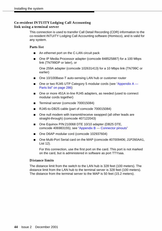
44 Issue 2 December 2001
Installing the system
Co-resident INTUITY Lodging Call Accountinglink using a terminal server
This connection is used to transfer Call Detail Recording (CDR) information to the co-resident INTUITY Lodging Call Accounting software (Homisco), and is valid for any system.
Parts list
■ An ethernet port on the C-LAN circuit pack
■ One IP Media Processor adapter (comcode 848525887) for a 100 Mbps link (TN799DP or later), or
One 259A adapter (comcode 102631413) for a 10 Mbps link (TN799C or earlier)
■ One 10/100Base-T auto-sensing LAN hub or customer router
■ One or two RJ45 UTP Category 5 modular cords (see “Appendix A — Parts list” on page 286)
■ One or more 451A in-line RJ45 adapters, as needed (used to connect modular cords together)
■ Terminal server (comcode 700015084)
■ RJ45-to-DB25 cable (part of comcode 700015084)
■ One null modem with transmit/receive swapped (all other leads are straight-through) (comcode 407122043)
■ One Equinox P/N:210068 DTE 10/10 adapter (DB25 DTE, comcode 406983155); see “Appendix B — Connector pinouts”
■ One D6AP modular cord (comcode 102937604)
■ One Multi-Port Serial card on the MAP (comcode 407009406; J1P260AA1, List 12).
For this connection, use the first port on the card. This port is not marked on the card, but is administered in software as port TTYsaa.
Distance limits
The distance limit from the switch to the LAN hub is 328 feet (100 meters). The distance limit from the LAN hub to the terminal server is 328 feet (100 meters). The distance from the terminal server to the MAP is 50 feet (15.2 meters).

Issue 2 December 2001 45
Connecting the hospitality adjuncts
Cabling diagram
Figure 14 shows the connection used to transfer CDR information between the switch and the MAP using a terminal server.
Figure 14. Co-resident INTUITY Lodging Call Accounting link using a terminal server
clan2map.cdr
Multi-PortSerial Card
TTYsaa(DTE)
MAP
D6APModular
Cord
EquinoxP/N:210068DTE 10/10
Adapter
C-LAN
Switch
Hub orRouter
328 ft max(100 m)
328 ft max(100 m)
AC Power
TerminalServer(DTE)
RJ45 Cat 5Modular Cord
RJ45 Cat 5Modular Cord
RJ45-to-DB25cable
50 ft max(15 m)
IP Media Processor Adapter (100 Mbps) or259A Adapter (10 Mbps) Null
modem

46 Issue 2 December 2001
Installing the system
Test procedure
Using the RS232 Mini-Tester (see the Note on page 5), check the status of the link where the Equinox adapter connects to the null modem as shown in Figure 14. The leads marked with an asterisk are controlled by the switch, and the INTUITY Lodging Call Accounting system controls the other leads. Translations for this connection begin on page 262.
! CAUTION:After using a mini-tester to check data leads, you MUST remove the mini-tester from the connection. DO NOT leave the mini-tester in-line during actual operation.
With the mini-tester connected to only the null modem on the terminal server port, the mini-tester should show the following:
With the mini-tester connected to only the Equinox adapter, the mini-tester should show the following:
TD
RTS
DTR
RD*
CTS*DSR*
CD*
dark
greendark
green
darkred
green
TD
RTS
DTR
RD*
CTS*DSR*
CD*
dark
red
red
greendark
dark
dark
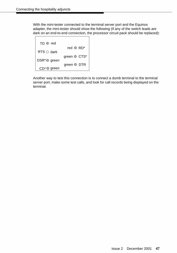
Issue 2 December 2001 47
Connecting the hospitality adjuncts
With the mini-tester connected to the terminal server port and the Equinox adapter, the mini-tester should show the following (if any of the switch leads are dark on an end-to-end connection, the processor circuit pack should be replaced):
Another way to test this connection is to connect a dumb terminal to the terminal server port, make some test calls, and look for call records being displayed on the terminal.
TD
RTS
DTR
RD*
CTS*DSR*
CD*
green
green
red
green
red
dark
green

48 Issue 2 December 2001
Installing the system
Xiox call accounting system link using aterminal server
This connection is used to transfer CDR information to the Xiox call accounting system. This connection is valid for any system.
Parts list
■ An ethernet port on the C-LAN circuit pack
■ One IP Media Processor adapter (comcode 848525887) for a 100 Mbps link (TN799DP or later), or
One 259A adapter (comcode 102631413) for a 10 Mbps link (TN799C or earlier)
■ One 10/100Base-T auto-sensing LAN hub or customer router
■ One or two RJ45 UTP Category 5 modular cords (see “Appendix A — Parts list” on page 286)
■ One or more 451A in-line RJ45 adapters, as needed (used to connect modular cords together)
■ Terminal server (comcode 700015084)
■ RJ45-to-DB25 cable (part of comcode 700015084)
■ One null modem with transmit/receive swapped (all other leads are straight-through) (comcode 407122043)
■ Xiox Intelligent Buffer unit (includes AC power adapter and cable for connecting to the Xiox call accounting PC)
■ Xiox call accounting PC
Distance limits
The distance limit from the switch to the LAN hub is 328 feet (100 meters). The distance limit from the LAN hub to the terminal server is 328 feet (100 meters). The distance from the terminal server to the Xiox call accounting PC is 50 feet (15.2 meters).

Issue 2 December 2001 49
Connecting the hospitality adjuncts
Cabling diagram
Figure 15 shows the connection between a terminal server port and a Xiox call accounting system.
Figure 15. Xiox call accounting system link using a terminal server
C-LAN
Switch
Hub orRouter
328 ft max(100 m)
328 ft max(100 m)
AC Power
RJ45 Cat 5Modular Cord
RJ45 Cat 5Modular Cord
clan2xiox.cdr
PBXRS232Cable
PC
Xiox CallAccounting PC
Xiox IntelligentBuffer(DTE)
COM1
DemarcationPoint
TerminalServer(DTE)
RJ45-to-DB25cable
50 ft max(15 m)
IP Media Processor Adapter (100 Mbps) or259A Adapter (10 Mbps)
Nullmodem

50 Issue 2 December 2001
Installing the system
Test procedure
Using the RS232 Mini-Tester (see the Note on page 5), check the status of the link at the point where the null modem connects to the Xiox Intelligent Buffer as shown in Figure 15. The leads marked with an asterisk are controlled by the switch, and the call accounting system controls the other leads. Translations for this connection begin on page 262.
! CAUTION:After using a mini-tester to check data leads, you MUST remove the mini-tester from the connection. DO NOT leave the mini-tester in-line during actual operation.
With the mini-tester connected to only the null modem from the terminal server port, the mini-tester should show the following:
With the mini-tester connected to only the PBX port on the Xiox Intelligent Buffer, the mini-tester should show the following:
TD
RTS
DTR
RD*
CTS*DSR*
CD*
dark
dark
green
green
red
green
dark
TD
RTS
DTR
RD*
CTS*DSR*
CD*
red
green
dark
dark
dark
dark
green
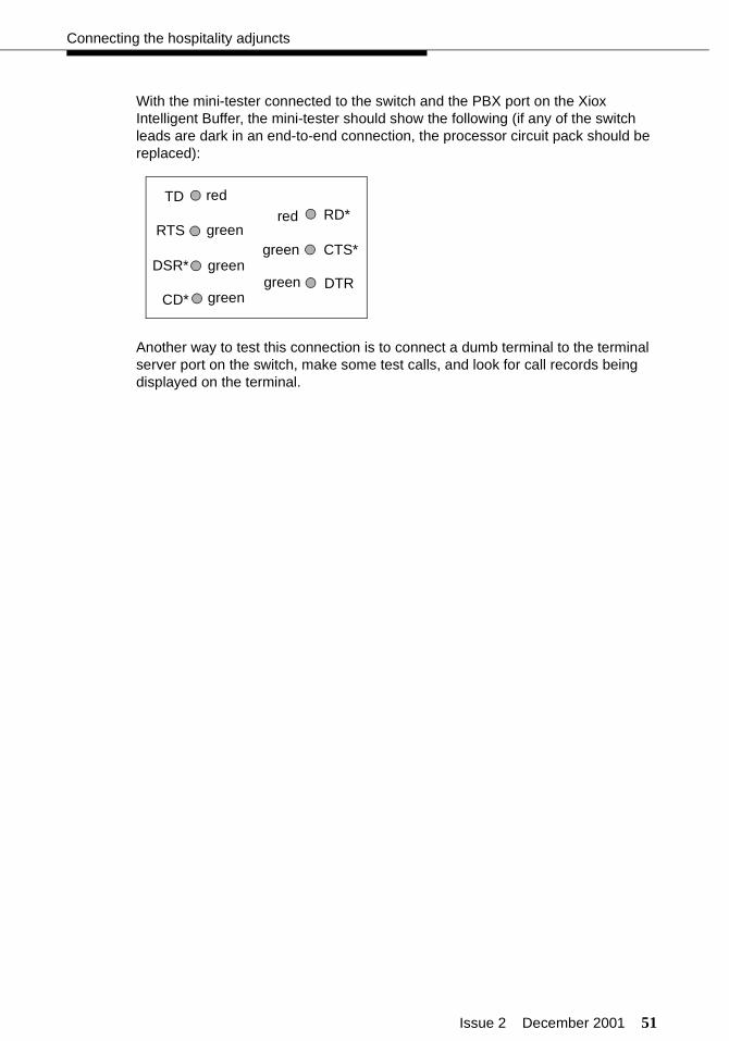
Issue 2 December 2001 51
Connecting the hospitality adjuncts
With the mini-tester connected to the switch and the PBX port on the Xiox Intelligent Buffer, the mini-tester should show the following (if any of the switch leads are dark in an end-to-end connection, the processor circuit pack should be replaced):
Another way to test this connection is to connect a dumb terminal to the terminal server port on the switch, make some test calls, and look for call records being displayed on the terminal.
TD
RTS
DTR
RD*
CTS*DSR*
CD*
red
green
green
green
red
green
green
52 Issue 2 December 2001
Installing the system
Stand-alone call accounting system linkusing a terminal server
This connection is used to transfer CDR information to a stand-alone call accounting system. This connection is valid for any system.
Parts list
■ An ethernet port on the C-LAN circuit pack
■ One IP Media Processor adapter (comcode 848525887) for a 100 Mbps link (TN799DP or later), or
One 259A adapter (comcode 102631413) for a 10 Mbps link (TN799C or earlier)
■ One 10/100Base-T auto-sensing LAN hub or customer router
■ One or two RJ45 UTP Category 5 modular cords (see “Appendix A — Parts list” on page 286)
■ One or more 451A in-line RJ45 adapters, as needed (used to connect modular cords together)
■ Terminal server (comcode 700015084)
■ RJ45-to-DB25 cable (part of comcode 700015084)
■ One null modem with transmit/receive swapped (all other leads are straight-through) (comcode 407122043)
Distance limits
The distance limit from the switch to the LAN hub is 328 feet (100 meters). The distance limit from the LAN hub to the terminal server is 328 feet (100 meters). The distance from the hub to the stand-alone call accounting system is 50 feet (15.2 meters).

Issue 2 December 2001 53
Connecting the hospitality adjuncts
Cabling diagram
Figure 16 shows the connection between the terminal server port and a stand-alone call accounting system.
Figure 16. Stand-alone call accounting system link using a terminal server
clan2gca.cdr
50 ft max(15 m)
StandaloneCall Accounting
CallAccounting
Port(DTE)
DemarcationPoint
C-LAN
Switch
Hub orRouter
328 ft max(100 m)
328 ft max(100 m)
AC Power
RJ45 Cat 5Modular Cord
RJ45 Cat 5Modular Cord
TerminalServer(DTE)
RJ45-to-DB25cable
IP Media Processor Adapter (100 Mbps) or259A Adapter (10 Mbps)
Nullmodem
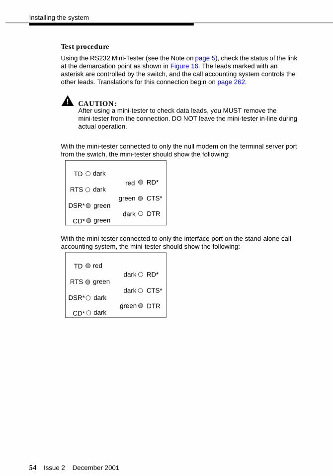
54 Issue 2 December 2001
Installing the system
Test procedure
Using the RS232 Mini-Tester (see the Note on page 5), check the status of the link at the demarcation point as shown in Figure 16. The leads marked with an asterisk are controlled by the switch, and the call accounting system controls the other leads. Translations for this connection begin on page 262.
! CAUTION:After using a mini-tester to check data leads, you MUST remove the mini-tester from the connection. DO NOT leave the mini-tester in-line during actual operation.
With the mini-tester connected to only the null modem on the terminal server port from the switch, the mini-tester should show the following:
With the mini-tester connected to only the interface port on the stand-alone call accounting system, the mini-tester should show the following:
TD
RTS
DTR
RD*
CTS*DSR*
CD*
dark
dark
green
green
red
green
dark
TD
RTS
DTR
RD*
CTS*DSR*
CD*
red
green
dark
dark
dark
dark
green
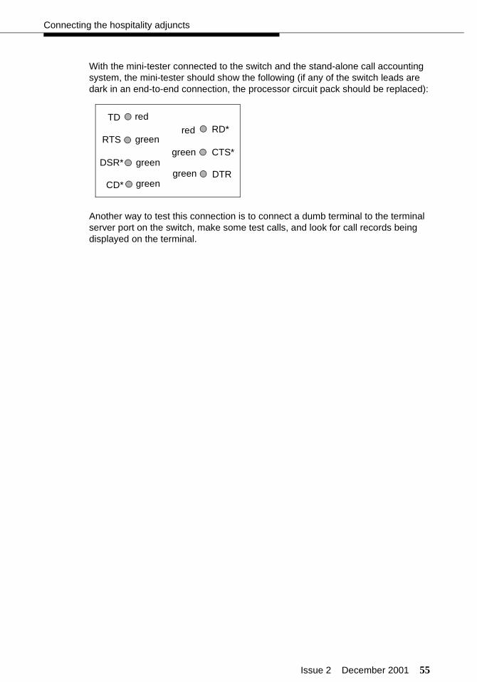
Issue 2 December 2001 55
Connecting the hospitality adjuncts
With the mini-tester connected to the switch and the stand-alone call accounting system, the mini-tester should show the following (if any of the switch leads are dark in an end-to-end connection, the processor circuit pack should be replaced):
Another way to test this connection is to connect a dumb terminal to the terminal server port on the switch, make some test calls, and look for call records being displayed on the terminal.
TD
RTS
DTR
RD*
CTS*DSR*
CD*
red
green
green
green
red
green
green
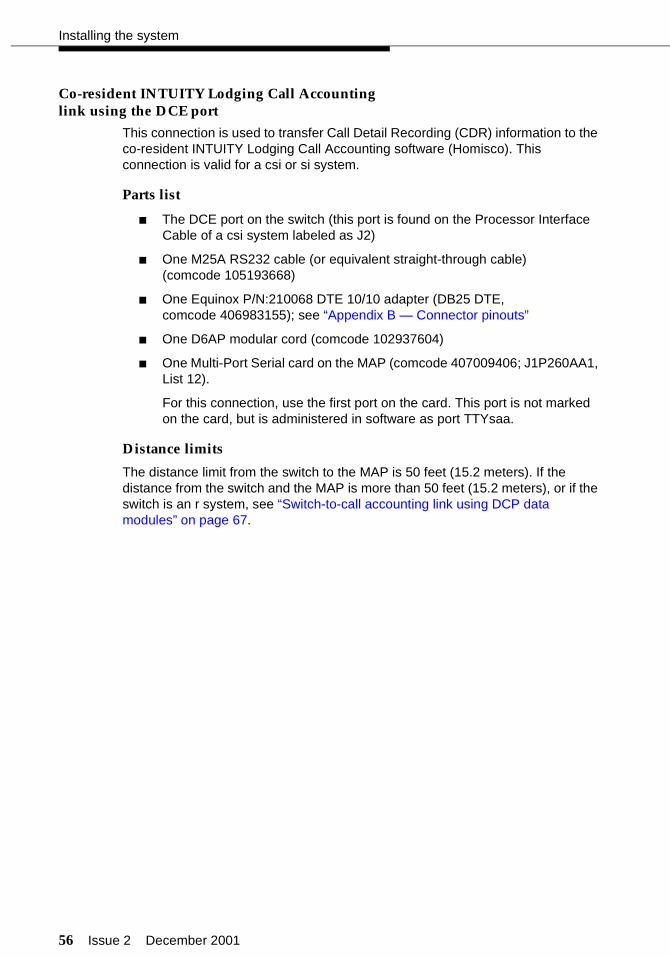
56 Issue 2 December 2001
Installing the system
Co-resident INTUITY Lodging Call Accountinglink using the DCE port
This connection is used to transfer Call Detail Recording (CDR) information to the co-resident INTUITY Lodging Call Accounting software (Homisco). This connection is valid for a csi or si system.
Parts list
■ The DCE port on the switch (this port is found on the Processor Interface Cable of a csi system labeled as J2)
■ One M25A RS232 cable (or equivalent straight-through cable) (comcode 105193668)
■ One Equinox P/N:210068 DTE 10/10 adapter (DB25 DTE, comcode 406983155); see “Appendix B — Connector pinouts”
■ One D6AP modular cord (comcode 102937604)
■ One Multi-Port Serial card on the MAP (comcode 407009406; J1P260AA1, List 12).
For this connection, use the first port on the card. This port is not marked on the card, but is administered in software as port TTYsaa.
Distance limits
The distance limit from the switch to the MAP is 50 feet (15.2 meters). If the distance from the switch and the MAP is more than 50 feet (15.2 meters), or if the switch is an r system, see “Switch-to-call accounting link using DCP data modules” on page 67.
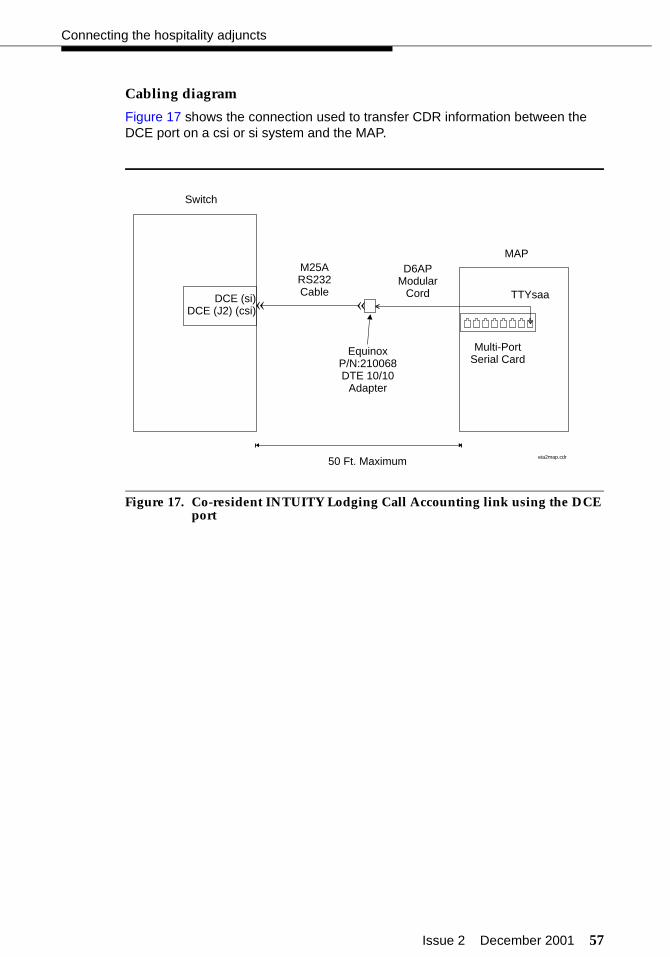
Issue 2 December 2001 57
Connecting the hospitality adjuncts
Cabling diagram
Figure 17 shows the connection used to transfer CDR information between the DCE port on a csi or si system and the MAP.
Figure 17. Co-resident INTUITY Lodging Call Accounting link using the DCE port
DCE (si)DCE (J2) (csi)
Switch
Multi-PortSerial Card
TTYsaa
MAP
50 Ft. Maximum
D6APModular
Cord
EquinoxP/N:210068DTE 10/10
Adapter
M25ARS232Cable
« «
eia2map.cdr

58 Issue 2 December 2001
Installing the system
Test procedure
Using the RS232 Mini-Tester (see the Note on page 5), check the status of the link where the Equinox adapter connects to the M25A cable as shown in Figure 17. The leads marked with an asterisk are controlled by the switch, and the INTUITY Lodging Call Accounting system controls the other leads. Translations for this begin on page 262.
! CAUTION:After using a mini-tester to check data leads, you MUST remove the mini-tester from the connection. DO NOT leave the mini-tester in-line during actual operation.
With the mini-tester connected to only the M25A cable, the mini-tester should show the following:
With the mini-tester connected to only the Equinox adapter, the mini-tester should show the following:
TD
RTS
DTR
RD*
CTS*DSR*
CD*
dark
greendark
green
darkred
green
TD
RTS
DTR
RD*
CTS*DSR*
CD*
dark
red
red
greendark
dark
dark

Issue 2 December 2001 59
Connecting the hospitality adjuncts
With the mini-tester connected to the M25A cable and the Equinox adapter, the mini-tester should show the following (if any of the switch leads are dark on an end-to-end connection, the processor circuit pack should be replaced):
Another way to test this connection is to connect a dumb terminal to the DCE port on the switch, make some test calls, and look for call records being displayed on the terminal.
TD
RTS
DTR
RD*
CTS*DSR*
CD*
green
green
red
green
red
dark
green
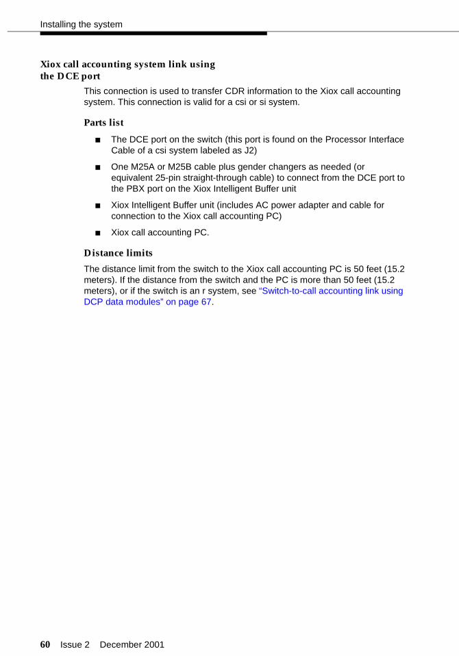
60 Issue 2 December 2001
Installing the system
Xiox call accounting system link usingthe DCE port
This connection is used to transfer CDR information to the Xiox call accounting system. This connection is valid for a csi or si system.
Parts list
■ The DCE port on the switch (this port is found on the Processor Interface Cable of a csi system labeled as J2)
■ One M25A or M25B cable plus gender changers as needed (or equivalent 25-pin straight-through cable) to connect from the DCE port to the PBX port on the Xiox Intelligent Buffer unit
■ Xiox Intelligent Buffer unit (includes AC power adapter and cable for connection to the Xiox call accounting PC)
■ Xiox call accounting PC.
Distance limits
The distance limit from the switch to the Xiox call accounting PC is 50 feet (15.2 meters). If the distance from the switch and the PC is more than 50 feet (15.2 meters), or if the switch is an r system, see “Switch-to-call accounting link using DCP data modules” on page 67.
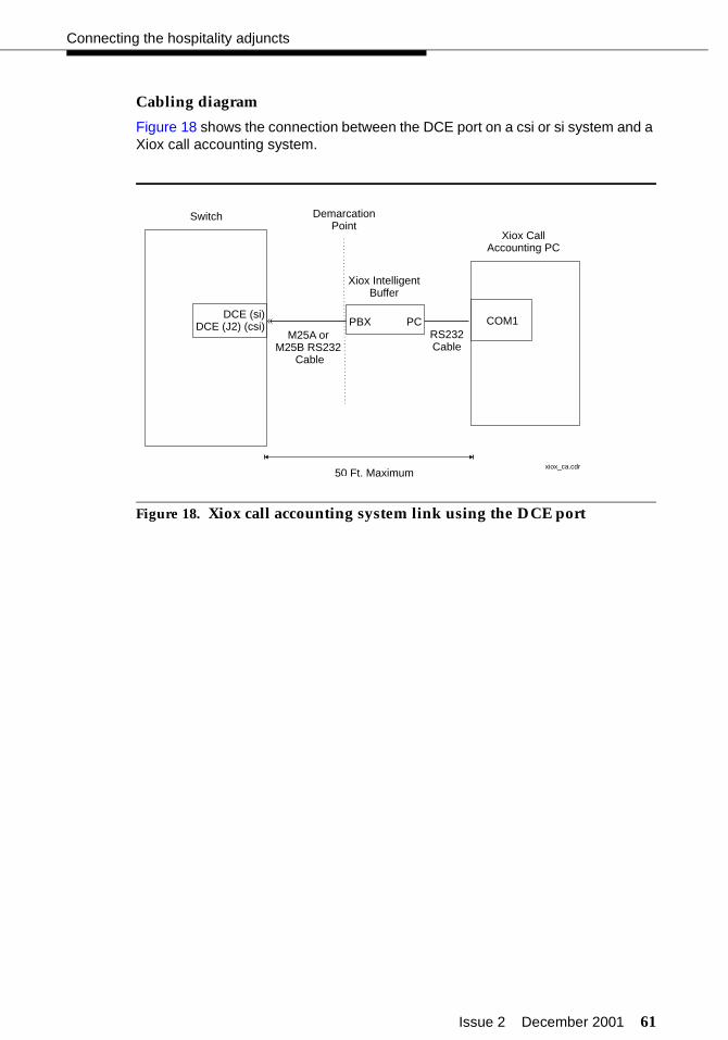
Issue 2 December 2001 61
Connecting the hospitality adjuncts
Cabling diagram
Figure 18 shows the connection between the DCE port on a csi or si system and a Xiox call accounting system.
Figure 18. Xiox call accounting system link using the DCE port
DCE (si)DCE (J2) (csi)
Switch
50 Ft. Maximum
Xiox CallAccounting PC
COM1
xiox_ca.cdr
PBXRS232Cable
PC
Xiox IntelligentBuffer
M25A orM25B RS232
Cable
«
DemarcationPoint
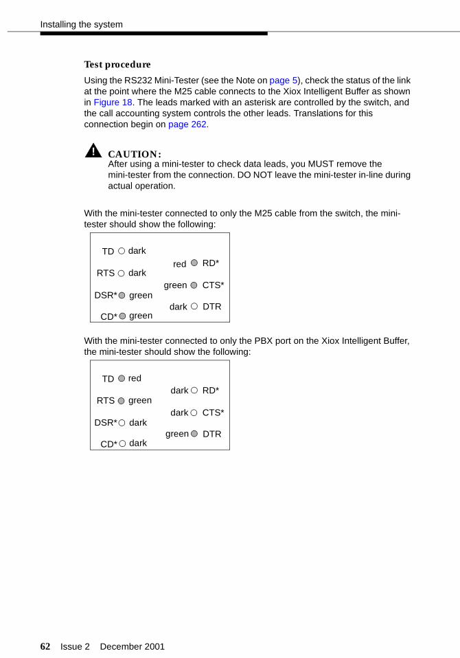
62 Issue 2 December 2001
Installing the system
Test procedure
Using the RS232 Mini-Tester (see the Note on page 5), check the status of the link at the point where the M25 cable connects to the Xiox Intelligent Buffer as shown in Figure 18. The leads marked with an asterisk are controlled by the switch, and the call accounting system controls the other leads. Translations for this connection begin on page 262.
! CAUTION:After using a mini-tester to check data leads, you MUST remove the mini-tester from the connection. DO NOT leave the mini-tester in-line during actual operation.
With the mini-tester connected to only the M25 cable from the switch, the mini-tester should show the following:
With the mini-tester connected to only the PBX port on the Xiox Intelligent Buffer, the mini-tester should show the following:
TD
RTS
DTR
RD*
CTS*DSR*
CD*
dark
dark
green
green
red
green
dark
TD
RTS
DTR
RD*
CTS*DSR*
CD*
red
green
dark
dark
dark
dark
green
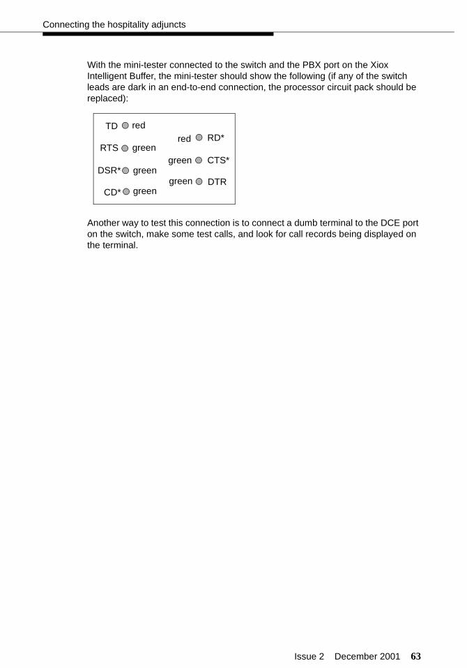
Issue 2 December 2001 63
Connecting the hospitality adjuncts
With the mini-tester connected to the switch and the PBX port on the Xiox Intelligent Buffer, the mini-tester should show the following (if any of the switch leads are dark in an end-to-end connection, the processor circuit pack should be replaced):
Another way to test this connection is to connect a dumb terminal to the DCE port on the switch, make some test calls, and look for call records being displayed on the terminal.
TD
RTS
DTR
RD*
CTS*DSR*
CD*
red
green
green
green
red
green
green
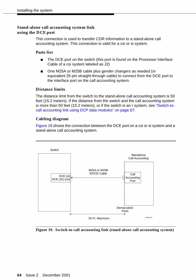
64 Issue 2 December 2001
Installing the system
Stand-alone call accounting system linkusing the DCE port
This connection is used to transfer CDR information to a stand-alone call accounting system. This connection is valid for a csi or si system.
Parts list
■ The DCE port on the switch (this port is found on the Processor Interface Cable of a csi system labeled as J2)
■ One M25A or M25B cable plus gender changers as needed (or equivalent 25-pin straight-through cable) to connect from the DCE port to the interface port on the call accounting system.
Distance limits
The distance limit from the switch to the stand-alone call accounting system is 50 feet (15.2 meters). If the distance from the switch and the call accounting system is more than 50 feet (15.2 meters), or if the switch is an r system, see “Switch-to-call accounting link using DCP data modules” on page 67.
Cabling diagram
Figure 19 shows the connection between the DCE port on a csi or si system and a stand-alone call accounting system.
Figure 19. Switch-to-call accounting link (stand-alone call accounting system)
DCE (si)DCE (J2) (csi)
Switch
50 Ft. Maximum
StandaloneCall Accounting
CallAccounting
Port
DemarcationPoint
M25A or M25BRS232 Cable
«
eia2gca.cdr

Issue 2 December 2001 65
Connecting the hospitality adjuncts
Test procedure
Using the RS232 Mini-Tester (see the Note on page 5), check the status of the link at the demarcation point as shown in Figure 19. The leads marked with an asterisk are controlled by the switch, and the call accounting system controls the other leads. Translations for this connection begin on page 262.
! CAUTION:After using a mini-tester to check data leads, you MUST remove the mini-tester from the connection. DO NOT leave the mini-tester in-line during actual operation.
With the mini-tester connected to only the M25 cable from the switch, the mini-tester should show the following:
With the mini-tester connected to only the interface port on the stand-alone call accounting system, the mini-tester should show the following:
TD
RTS
DTR
RD*
CTS*DSR*
CD*
dark
dark
green
green
red
green
dark
TD
RTS
DTR
RD*
CTS*DSR*
CD*
red
green
dark
dark
dark
dark
green
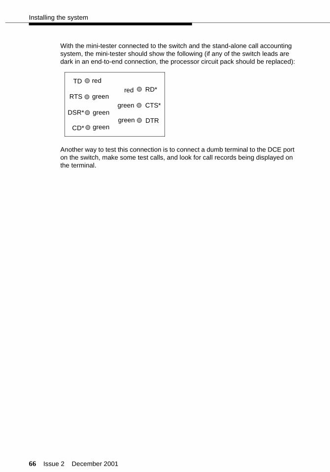
66 Issue 2 December 2001
Installing the system
With the mini-tester connected to the switch and the stand-alone call accounting system, the mini-tester should show the following (if any of the switch leads are dark in an end-to-end connection, the processor circuit pack should be replaced):
Another way to test this connection is to connect a dumb terminal to the DCE port on the switch, make some test calls, and look for call records being displayed on the terminal.
TD
RTS
DTR
RD*
CTS*DSR*
CD*
red
green
green
green
red
green
green
Issue 2 December 2001 67
Connecting the hospitality adjuncts
Switch-to-call accounting link using DCPdata modules
This connection is used when the distance between the switch and the call accounting system is greater than 50 feet (15.2 meters), or when using an r system.
Parts list
Co-Resident INTUITY Lodging Call Accounting (Homisco)
■ One digital communications protocol (DCP) port on the switch; the 8400B data module uses a TN2214 or TN2224 2-wire digital port, and the 7400A and 7400B data modules use a TN754C 4-wire digital port
■ Standard cross-connect hardware
■ One D8W modular cord
■ One 8400B data module optioned as shown on page 69, a 7400A data module optioned as shown in Table 5, or a 7400B data module optioned as shown on page 71
■ One DB9-to-DB25 transition cable when using the 8400B data module
■ One Equinox P/N:210068 DTE 10/10 adapter (DB25 DTE, comcode 406983155); see “Appendix B — Connector pinouts”
■ One D6AP modular cord (comcode 102937604).
Xiox or other stand-alone call accounting system
■ One digital communications protocol (DCP) port on the switch; the 8400B data module uses a TN2214 or TN2224 2-wire digital port, and the 7400A and 7400B data modules use a TN754C 4-wire digital port
■ Standard cross-connect hardware
■ One D8W modular cord
■ One 8400B data module optioned as shown on page 69, a 7400A data module optioned as shown in Table 5 on Page 70, or a 7400B data module optioned as shown on page 71
■ One DB9-to-DB25 transition cable when using the 8400B data module
■ One M25A or M25B cable (or equivalent 25-pin straight-through cable); see “Appendix A — Parts list” on page 286.
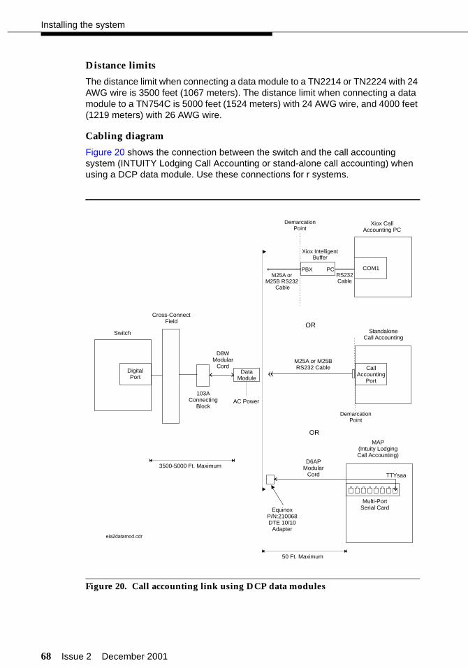
68 Issue 2 December 2001
Installing the system
Distance limits
The distance limit when connecting a data module to a TN2214 or TN2224 with 24 AWG wire is 3500 feet (1067 meters). The distance limit when connecting a data module to a TN754C is 5000 feet (1524 meters) with 24 AWG wire, and 4000 feet (1219 meters) with 26 AWG wire.
Cabling diagram
Figure 20 shows the connection between the switch and the call accounting system (INTUITY Lodging Call Accounting or stand-alone call accounting) when using a DCP data module. Use these connections for r systems.
Figure 20. Call accounting link using DCP data modules
DigitalPort
CallAccounting
Port
Switch
DataModule
Cross-ConnectField
D8WModular
Cord
103AConnecting
BlockAC Power
M25A or M25BRS232 Cable
«
MAP(Intuity LodgingCall Accounting)
OR
OR
Multi-PortSerial Card
TTYsaa
StandaloneCall Accounting
D6APModular
Cord
EquinoxP/N:210068DTE 10/10
Adapter
Xiox CallAccounting PC
COM1
eia2datamod.cdr
PBXRS232Cable
PC
Xiox IntelligentBuffer
M25A orM25B RS232
Cable
«
DemarcationPoint
DemarcationPoint
50 Ft. Maximum
3500-5000 Ft. Maximum
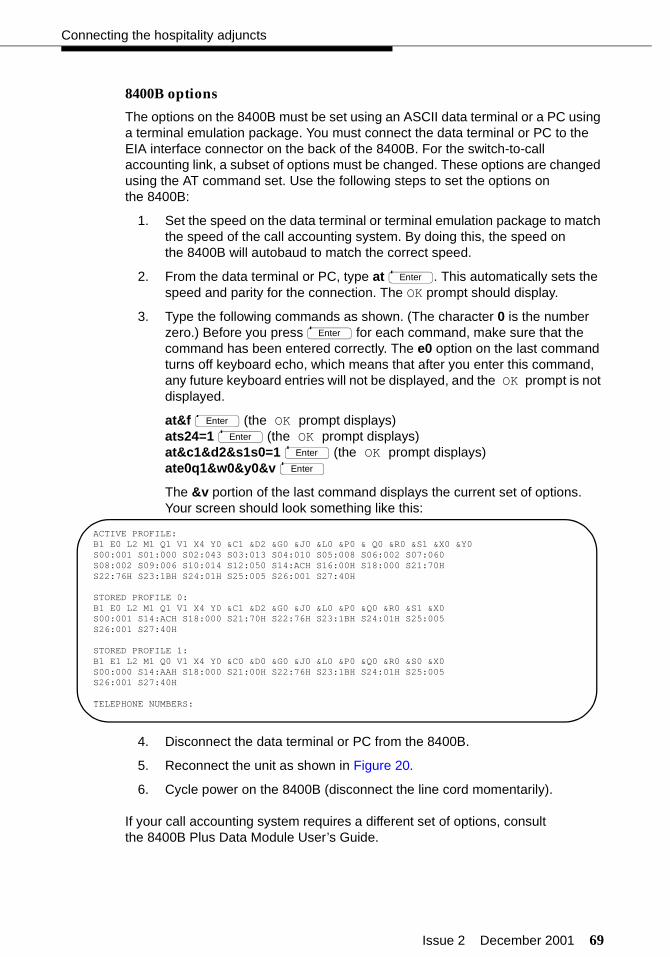
Issue 2 December 2001 69
Connecting the hospitality adjuncts
8400B options
The options on the 8400B must be set using an ASCII data terminal or a PC using a terminal emulation package. You must connect the data terminal or PC to the EIA interface connector on the back of the 8400B. For the switch-to-call accounting link, a subset of options must be changed. These options are changed using the AT command set. Use the following steps to set the options on the 8400B:
1. Set the speed on the data terminal or terminal emulation package to match the speed of the call accounting system. By doing this, the speed on the 8400B will autobaud to match the correct speed.
2. From the data terminal or PC, type at . This automatically sets the speed and parity for the connection. The OK prompt should display.
3. Type the following commands as shown. (The character 0 is the number zero.) Before you press for each command, make sure that the command has been entered correctly. The e0 option on the last command turns off keyboard echo, which means that after you enter this command, any future keyboard entries will not be displayed, and the OK prompt is not displayed.
at&f (the OK prompt displays)ats24=1 (the OK prompt displays)at&c1&d2&s1s0=1 (the OK prompt displays)ate0q1&w0&y0&v
The &v portion of the last command displays the current set of options. Your screen should look something like this:
4. Disconnect the data terminal or PC from the 8400B.
5. Reconnect the unit as shown in Figure 20.
6. Cycle power on the 8400B (disconnect the line cord momentarily).
If your call accounting system requires a different set of options, consult the 8400B Plus Data Module User’s Guide.
Enter
Enter
Enter
Enter
Enter
Enter
ACTIVE PROFILE:B1 E0 L2 M1 Q1 V1 X4 Y0 &C1 &D2 &G0 &J0 &L0 &P0 & Q0 &R0 &S1 &X0 &Y0S00:001 S01:000 S02:043 S03:013 S04:010 S05:008 S06:002 S07:060S08:002 S09:006 S10:014 S12:050 S14:ACH S16:00H S18:000 S21:70HS22:76H S23:1BH S24:01H S25:005 S26:001 S27:40H
STORED PROFILE 0:B1 E0 L2 M1 Q1 V1 X4 Y0 &C1 &D2 &G0 &J0 &L0 &P0 &Q0 &R0 &S1 &X0S00:001 S14:ACH S18:000 S21:70H S22:76H S23:1BH S24:01H S25:005S26:001 S27:40H
STORED PROFILE 1:B1 E1 L2 M1 Q0 V1 X4 Y0 &C0 &D0 &G0 &J0 &L0 &P0 &Q0 &R0 &S0 &X0S00:000 S14:AAH S18:000 S21:00H S22:76H S23:1BH S24:01H S25:005S26:001 S27:40H
TELEPHONE NUMBERS:
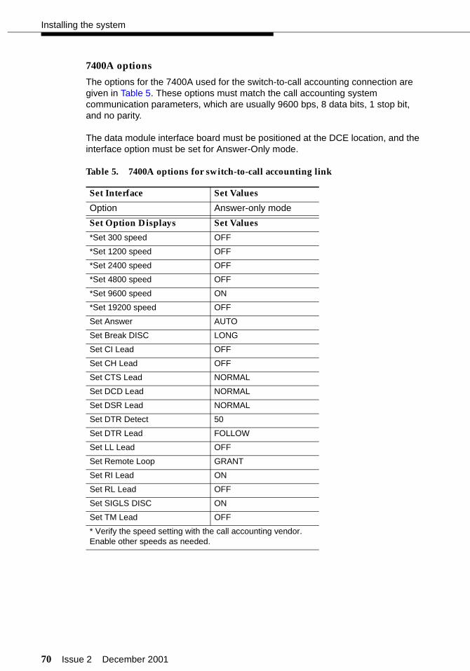
70 Issue 2 December 2001
Installing the system
7400A options
The options for the 7400A used for the switch-to-call accounting connection are given in Table 5. These options must match the call accounting system communication parameters, which are usually 9600 bps, 8 data bits, 1 stop bit, and no parity.
The data module interface board must be positioned at the DCE location, and the interface option must be set for Answer-Only mode.
Table 5. 7400A options for switch-to-call accounting link
Set Interface Set Values
Option Answer-only mode
Set Option Displays Set Values
*Set 300 speed OFF
*Set 1200 speed OFF
*Set 2400 speed OFF
*Set 4800 speed OFF
*Set 9600 speed ON
*Set 19200 speed OFF
Set Answer AUTO
Set Break DISC LONG
Set CI Lead OFF
Set CH Lead OFF
Set CTS Lead NORMAL
Set DCD Lead NORMAL
Set DSR Lead NORMAL
Set DTR Detect 50
Set DTR Lead FOLLOW
Set LL Lead OFF
Set Remote Loop GRANT
Set RI Lead ON
Set RL Lead OFF
Set SIGLS DISC ON
Set TM Lead OFF
* Verify the speed setting with the call accounting vendor. Enable other speeds as needed.
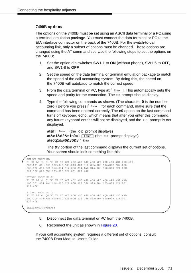
Issue 2 December 2001 71
Connecting the hospitality adjuncts
7400B options
The options on the 7400B must be set using an ASCII data terminal or a PC using a terminal emulation package. You must connect the data terminal or PC to the EIA interface connector on the back of the 7400B. For the switch-to-call accounting link, only a subset of options must be changed. These options are changed using the AT command set. Use the following steps to set the options on the 7400B:
1. Set the option dip switches SW1-1 to ON (without phone), SW1-5 to OFF, and SW1-8 to OFF.
2. Set the speed on the data terminal or terminal emulation package to match the speed of the call accounting system. By doing this, the speed on the 7400B will autobaud to match the correct speed.
3. From the data terminal or PC, type at . This automatically sets the speed and parity for the connection. The OK prompt should display.
4. Type the following commands as shown. (The character 0 is the number zero.) Before you press for each command, make sure that the command has been entered correctly. The e0 option on the last command turns off keyboard echo, which means that after you enter this command, any future keyboard entries will not be displayed, and the OK prompt is not displayed.
at&f (the OK prompt displays)at&c1&d2&s1s0=1 (the OK prompt displays)ate0q1&w0&y0&v
The &v portion of the last command displays the current set of options. Your screen should look something like this:
5. Disconnect the data terminal or PC from the 7400B.
6. Reconnect the unit as shown in Figure 20.
If your call accounting system requires a different set of options, consult the 7400B Data Module User’s Guide.
Enter
Enter
Enter
Enter
Enter
ACTIVE PROFILE:B1 E0 L2 M1 Q1 V1 X4 Y0 &C1 &D2 &G0 &J0 &L0 &P0 &Q0 &R0 &S1 &X0 &Y0S00:001 S01:000 S02:043 S03:013 S04:010 S05:008 S06:002 S07:060S08:002 S09:006 S10:014 S12:050 S14:AAH S16:00H S18:000 S21:00HS22:76H S23:0BH S25:005 S26:001 S27:40H
STORED PROFILE 0:B1 E0 L2 M1 Q1 V1 X1 Y0 &C1 &D2 &G0 &J0 &L0 &P0 &Q0 &R0 &S1 &X0S00:001 S14:AAH S18:000 S21:00H S22:76H S23:0BH S25:005 S26:001S27:40H
STORED PROFILE 1:B1 E1 L2 M1 Q0 V1 X4 Y0 &C0 &D0 &G0 &J0 &L0 &P0 &Q0 &R0 &S0 &X0S00:000 S14:AAH S18:000 S21:00H S22:76H S23:1BH S25:005 S26:001S27:40H
TELEPHONE NUMBERS:

72 Issue 2 December 2001
Installing the system
INTUITY Lodging Call Accounting-to-PMS link
This connection is used to transmit the call accounting information from the MAP to the PMS. This call detail information has been reformatted from its format on the switch for use by the PMS.
NOTE:This link between the co-resident INTUITY Lodging Call Accounting package and the PMS is required to transmit call detail records between the call accounting system and the PMS. This link is separate and distinct from the INTUITY Lodging-to-PMS link described on page 39.
Parts list
■ One Multi-Port Serial card on the MAP (comcode 407009406; J1P260AA1, List 12)
For this connection, use the second port on the card. This port is not marked on the card, but is administered in software as port TTYsab.
■ One D6AP modular cord (comcode 102937604)
■ One Equinox P/N:210068 DTE 10/10 adapter (DB25 DTE, comcode 406983155); see “Appendix B — Connector pinouts”
■ Gender changers, as needed.
Distance limits
The distance limit from the MAP to the PMS is 50 feet (15.2 meters).
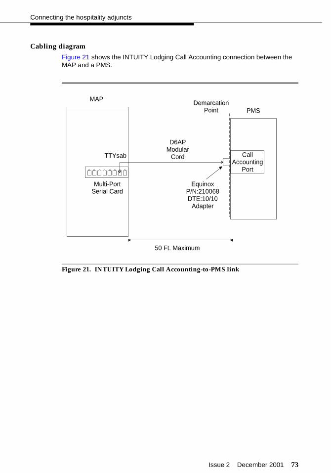
Issue 2 December 2001 73
Connecting the hospitality adjuncts
Cabling diagram
Figure 21 shows the INTUITY Lodging Call Accounting connection between the MAP and a PMS.
Figure 21. INTUITY Lodging Call Accounting-to-PMS link
MAP
D6APModular
Cord CallAccounting
Port
EquinoxP/N:210068DTE:10/10
Adapter
50 Ft. Maximum
PMSDemarcation
Point
Multi-PortSerial Card
TTYsab
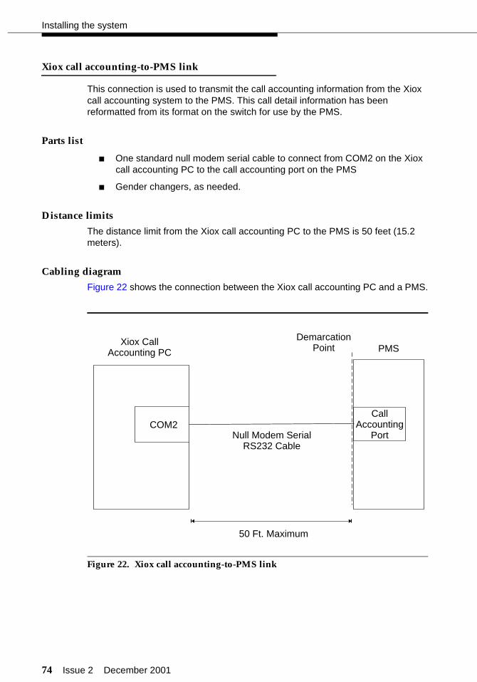
74 Issue 2 December 2001
Installing the system
Xiox call accounting-to-PMS link
This connection is used to transmit the call accounting information from the Xiox call accounting system to the PMS. This call detail information has been reformatted from its format on the switch for use by the PMS.
Parts list
■ One standard null modem serial cable to connect from COM2 on the Xiox call accounting PC to the call accounting port on the PMS
■ Gender changers, as needed.
Distance limits
The distance limit from the Xiox call accounting PC to the PMS is 50 feet (15.2 meters).
Cabling diagram
Figure 22 shows the connection between the Xiox call accounting PC and a PMS.
Figure 22. Xiox call accounting-to-PMS link
CallAccounting
Port
50 Ft. Maximum
PMSDemarcation
PointXiox Call
Accounting PC
COM2Null Modem Serial
RS232 Cable
Issue 2 December 2001 75
Connecting the hospitality adjuncts
Switch-to-PMS link
This connection is used to transfer the normal hospitality information, such as names registration, check-in, check-out, and so on, between the switch and the PMS.
This connection is used to transfer the normal hospitality information, such as names registration, check-in, check-out, and so on, between the switch and the PMS. This connection can be done in either of two different ways:
■ “PMS link using a terminal server”
■ “PMS link using a data module” on page 77
PMS link using a terminal server
This section describes how to connect the switch to a PMS using a terminal server.
Parts list
■ An ethernet port on the C-LAN circuit pack
■ One IP Media Processor adapter (comcode 848525887) for a 100 Mbps link (TN799DP or later), or
One 259A adapter (comcode 102631413) for a 10 Mbps link (TN799C or earlier)
■ One 10/100Base-T auto-sensing LAN hub or customer router
■ One or two RJ45 UTP Category 5 modular cords (see “Appendix A — Parts list” on page 286)
■ One or more 451A in-line RJ45 adapters, as needed (used to connect modular cords together)
■ Terminal server (comcode 700015084)
■ RJ45-to-DB25 cable (part of comcode 700015084)
■ One null modem with transmit/receive swapped (all other leads are straight-through) (comcode 407122043)
Distance limits
The distance limit from the switch to the LAN hub is 328 feet (100 meters). The distance limit from the LAN hub to the terminal server is 328 feet (100 meters). The distance from the hub to the PMS is 50 feet (15.2 meters).
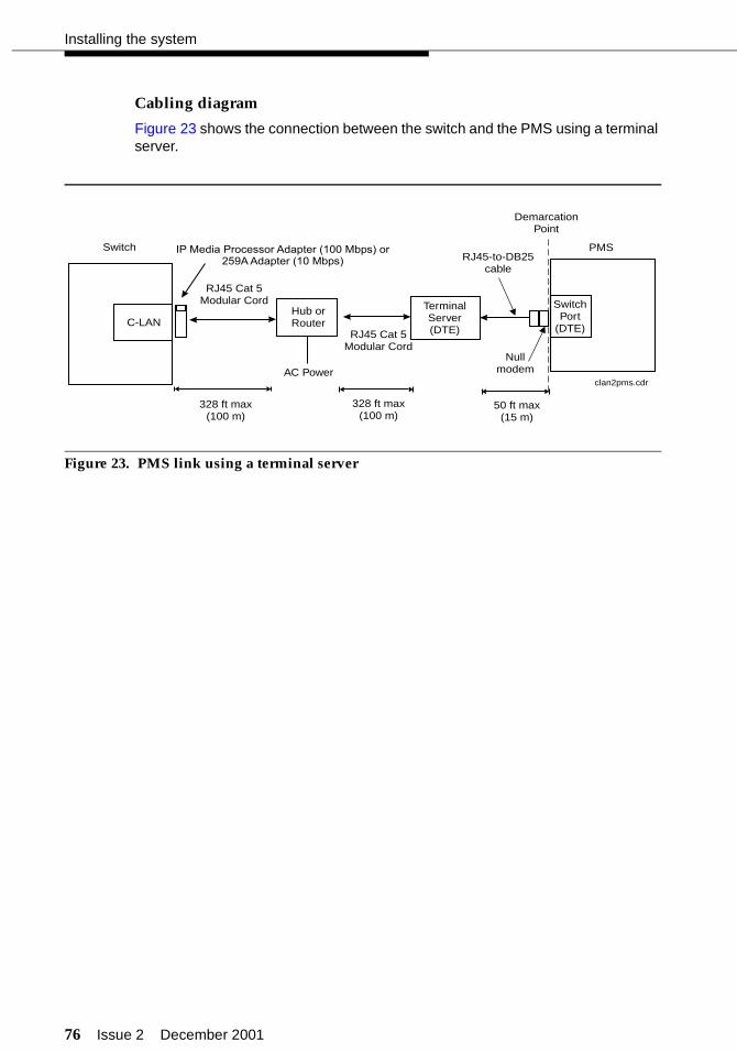
76 Issue 2 December 2001
Installing the system
Cabling diagram
Figure 23 shows the connection between the switch and the PMS using a terminal server.
Figure 23. PMS link using a terminal server
clan2pms.cdr
SwitchPort
(DTE)
PMS
DemarcationPoint
C-LAN
Switch
Hub orRouter
328 ft max(100 m)
328 ft max(100 m)
AC Power
RJ45 Cat 5Modular Cord
RJ45 Cat 5Modular Cord
TerminalServer(DTE)
RJ45-to-DB25cable
50 ft max(15 m)
IP Media Processor Adapter (100 Mbps) or259A Adapter (10 Mbps)
Nullmodem

Issue 2 December 2001 77
Connecting the hospitality adjuncts
PMS link using a data module
This section describes how to connect the switch to a PMS using a data module.
Parts list
■ One digital communications protocol (DCP) port on the switch; the 8400B data module uses a TN2214 or TN2224 2-wire digital port, and the 7400A and 7400B data modules use a TN754C 4-wire digital port.
■ Standard cross-connect hardware
■ One D8W modular cord
■ One 8400B data module optioned as shown on page 79, a 7400A DCP data module optioned as shown in Table 6 on Page 80, or a 7400B DCP data module optioned as shown on page 81
■ One DB9-to-DB25 transition cable when using the 8400B data module
■ One M25A or M25B cable (or equivalent 25-pin straight-through cable); see “Appendix A — Parts list” on page 286.
Distance limits
The distance limit when connecting a data module to a TN2214 or TN2224 with 24 AWG wire is 3500 feet (1067 meters). The distance limit when connecting a data module to a TN754C is 5000 feet (1524 meters) with 24 AWG wire, and 4000 feet (1219 meters) with 26 AWG wire.
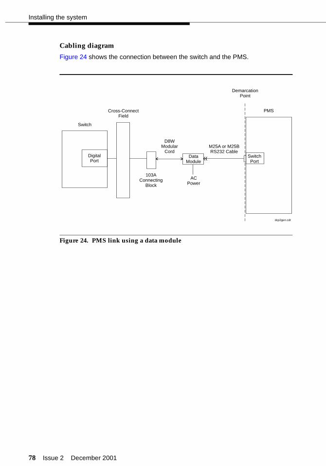
78 Issue 2 December 2001
Installing the system
Cabling diagram
Figure 24 shows the connection between the switch and the PMS.
Figure 24. PMS link using a data module
DigitalPort
Switch
DataModule
Cross-ConnectField
D8WModular
Cord
ACPower
103AConnecting
Block
M25A or M25BRS232 Cable
SwitchPort
PMS
DemarcationPoint
«
dcp2gen.cdr
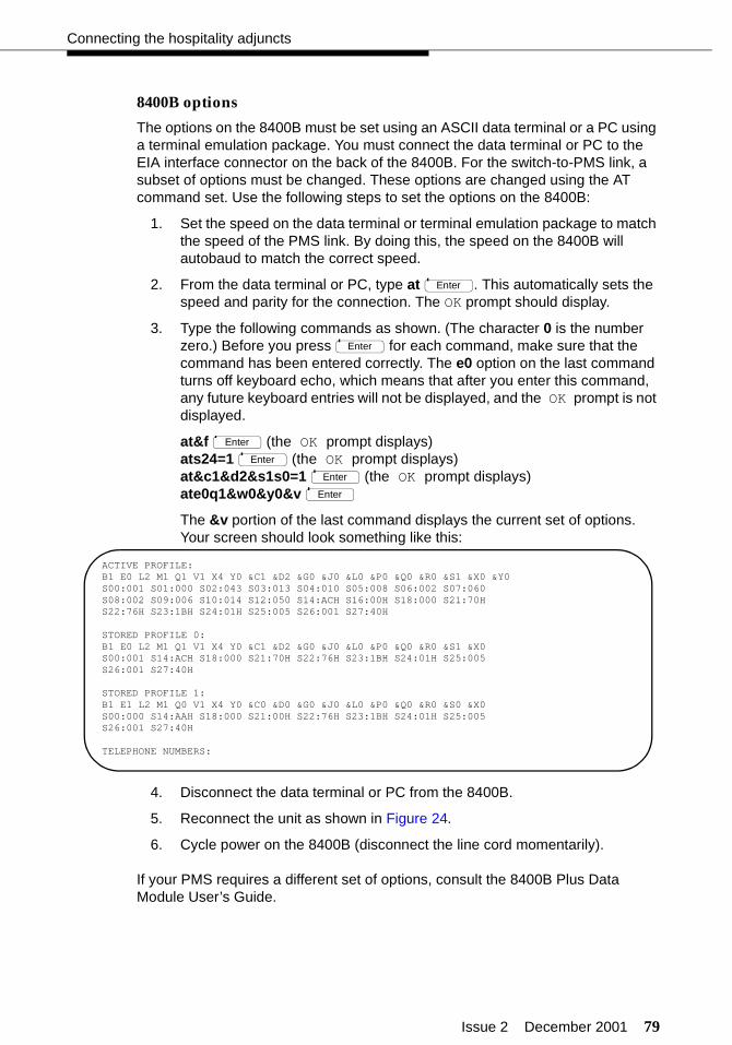
Issue 2 December 2001 79
Connecting the hospitality adjuncts
8400B options
The options on the 8400B must be set using an ASCII data terminal or a PC using a terminal emulation package. You must connect the data terminal or PC to the EIA interface connector on the back of the 8400B. For the switch-to-PMS link, a subset of options must be changed. These options are changed using the AT command set. Use the following steps to set the options on the 8400B:
1. Set the speed on the data terminal or terminal emulation package to match the speed of the PMS link. By doing this, the speed on the 8400B will autobaud to match the correct speed.
2. From the data terminal or PC, type at . This automatically sets the speed and parity for the connection. The OK prompt should display.
3. Type the following commands as shown. (The character 0 is the number zero.) Before you press for each command, make sure that the command has been entered correctly. The e0 option on the last command turns off keyboard echo, which means that after you enter this command, any future keyboard entries will not be displayed, and the OK prompt is not displayed.
at&f (the OK prompt displays)ats24=1 (the OK prompt displays)at&c1&d2&s1s0=1 (the OK prompt displays)ate0q1&w0&y0&v
The &v portion of the last command displays the current set of options. Your screen should look something like this:
4. Disconnect the data terminal or PC from the 8400B.
5. Reconnect the unit as shown in Figure 24.
6. Cycle power on the 8400B (disconnect the line cord momentarily).
If your PMS requires a different set of options, consult the 8400B Plus Data Module User’s Guide.
Enter
Enter
Enter
Enter
Enter
Enter
ACTIVE PROFILE:B1 E0 L2 M1 Q1 V1 X4 Y0 &C1 &D2 &G0 &J0 &L0 &P0 &Q0 &R0 &S1 &X0 &Y0S00:001 S01:000 S02:043 S03:013 S04:010 S05:008 S06:002 S07:060S08:002 S09:006 S10:014 S12:050 S14:ACH S16:00H S18:000 S21:70HS22:76H S23:1BH S24:01H S25:005 S26:001 S27:40H
STORED PROFILE 0:B1 E0 L2 M1 Q1 V1 X4 Y0 &C1 &D2 &G0 &J0 &L0 &P0 &Q0 &R0 &S1 &X0S00:001 S14:ACH S18:000 S21:70H S22:76H S23:1BH S24:01H S25:005S26:001 S27:40H
STORED PROFILE 1:B1 E1 L2 M1 Q0 V1 X4 Y0 &C0 &D0 &G0 &J0 &L0 &P0 &Q0 &R0 &S0 &X0S00:000 S14:AAH S18:000 S21:00H S22:76H S23:1BH S24:01H S25:005S26:001 S27:40H
TELEPHONE NUMBERS:

80 Issue 2 December 2001
Installing the system
7400A options
The options for the 7400A used for the switch-to-PMS connection are given in Table 6. These options must match the PMS communication parameters, which are usually 9600 bps, 8 data bits, 1 stop bit, and no parity.
The data module interface board must be positioned at the DCE location, and the interface option must be set for Answer-Only mode.
Table 6. 7400A options for switch-to-PMS link
Set Interface Set Values
Option Answer-only mode
Set Option Displays Set Values
*Set 300 speed OFF
*Set 1200 speed OFF
*Set 2400 speed OFF
*Set 4800 speed OFF
*Set 9600 speed ON
*Set 19200 speed OFF
Set Answer AUTO
Set Break DISC LONG
Set CI Lead OFF
Set CH Lead OFF
Set CTS Lead NORMAL
Set DCD Lead NORMAL
Set DSR Lead NORMAL
Set DTR Detect 50
Set DTR Lead FOLLOW
Set LL Lead OFF
Set Remote Loop GRANT
Set RI Lead ON
Set RL Lead OFF
Set SIGLS DISC ON
Set TM Lead OFF
* The speed is typically set to 9600 for Transparent mode and 1200 for Normal mode. Verify the speed setting with the PMS vendor. Enable other speeds as needed.
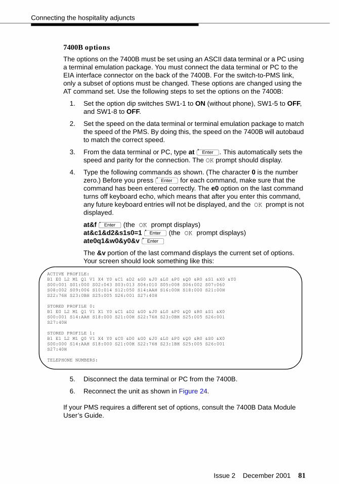
Issue 2 December 2001 81
Connecting the hospitality adjuncts
7400B options
The options on the 7400B must be set using an ASCII data terminal or a PC using a terminal emulation package. You must connect the data terminal or PC to the EIA interface connector on the back of the 7400B. For the switch-to-PMS link, only a subset of options must be changed. These options are changed using the AT command set. Use the following steps to set the options on the 7400B:
1. Set the option dip switches SW1-1 to ON (without phone), SW1-5 to OFF, and SW1-8 to OFF.
2. Set the speed on the data terminal or terminal emulation package to match the speed of the PMS. By doing this, the speed on the 7400B will autobaud to match the correct speed.
3. From the data terminal or PC, type at . This automatically sets the speed and parity for the connection. The OK prompt should display.
4. Type the following commands as shown. (The character 0 is the number zero.) Before you press for each command, make sure that the command has been entered correctly. The e0 option on the last command turns off keyboard echo, which means that after you enter this command, any future keyboard entries will not be displayed, and the OK prompt is not displayed.
at&f (the OK prompt displays)at&c1&d2&s1s0=1 (the OK prompt displays)ate0q1&w0&y0&v
The &v portion of the last command displays the current set of options. Your screen should look something like this:
5. Disconnect the data terminal or PC from the 7400B.
6. Reconnect the unit as shown in Figure 24.
If your PMS requires a different set of options, consult the 7400B Data Module User’s Guide.
Enter
Enter
Enter
Enter
Enter
ACTIVE PROFILE:B1 E0 L2 M1 Q1 V1 X4 Y0 &C1 &D2 &G0 &J0 &L0 &P0 &Q0 &R0 &S1 &X0 &Y0S00:001 S01:000 S02:043 S03:013 S04:010 S05:008 S06:002 S07:060S08:002 S09:006 S10:014 S12:050 S14:AAH S16:00H S18:000 S21:00HS22:76H S23:0BH S25:005 S26:001 S27:40H
STORED PROFILE 0:B1 E0 L2 M1 Q1 V1 X1 Y0 &C1 &D2 &G0 &J0 &L0 &P0 &Q0 &R0 &S1 &X0S00:001 S14:AAH S18:000 S21:00H S22:76H S23:0BH S25:005 S26:001S27:40H
STORED PROFILE 1:B1 E1 L2 M1 Q0 V1 X4 Y0 &C0 &D0 &G0 &J0 &L0 &P0 &Q0 &R0 &S0 &X0S00:000 S14:AAH S18:000 S21:00H S22:76H S23:1BH S25:005 S26:001S27:40H
TELEPHONE NUMBERS:

82 Issue 2 December 2001
Installing the system
Test procedure
Using the RS232 Mini-Tester (see the Note on page 5), check the status of the link at the null modem or data module before you connect to the PMS. The leads marked with an asterisk are controlled by the switch, and the PMS controls the other leads. Translations for this connection begin on page 189.
! CAUTION:After using a mini-tester to check data leads, you MUST remove the mini-tester from the connection. DO NOT leave the mini-tester in-line during actual operation.
With the mini-tester connected to only the null modem of the terminal server (Figure 23 on page 76) or to only the data module (Figure 24 on page 78), the mini-tester should show the following:
NOTE:The CTS lead shows green when used with an 8400B. RTS will be lit on the front panel of the 7400A or 7400B.
With the mini-tester connected to only the PMS, the mini-tester should show the following:
TD
RTS
DTR
RD*
CTS*DSR*
CD*
reddark
darkgreen
green
greendark
TD
RTS
DTR
RD*
CTS*DSR*
CD*
red
green
dark
dark
dark
dark
green
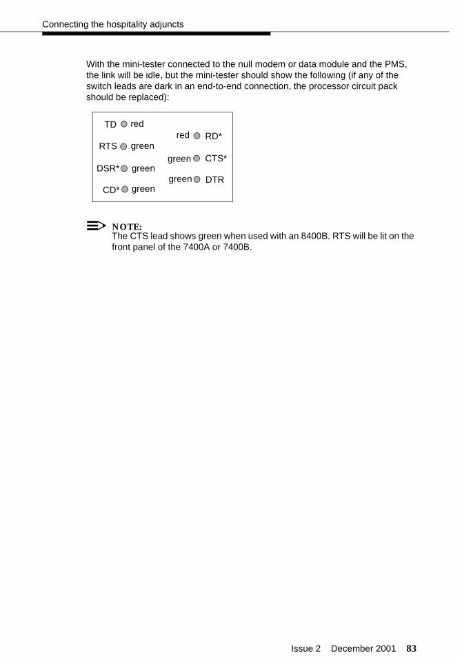
Issue 2 December 2001 83
Connecting the hospitality adjuncts
With the mini-tester connected to the null modem or data module and the PMS, the link will be idle, but the mini-tester should show the following (if any of the switch leads are dark in an end-to-end connection, the processor circuit pack should be replaced):
NOTE:The CTS lead shows green when used with an 8400B. RTS will be lit on the front panel of the 7400A or 7400B.
TD
RTS
DTR
RD*
CTS*DSR*
CD*
red
green
green
green
red
green
green
84 Issue 2 December 2001
Installing the system
Journal/PMS log or system printer connections
These serial printers are used to run hospitality service reports, to report failed Automatic Wakeup calls and Do Not Disturb requests, or to run Basic Call Management System (BCMS) reports.
NOTE:In most cases, only one printer is provided to perform both the journal/schedule and PMS log printer functions. The system printer is usually a separate printer.
Connecting serial printers can be done in either of two different ways:
■ “Printer connections using a terminal server” on page 85
■ “Printer connections using a data module” on page 87
Issue 2 December 2001 85
Connecting the hospitality adjuncts
Printer connections using a terminal server
This section describes how you connect a serial printer to the switch using a terminal server.
! CAUTION:Using a terminal server to connect a printer does not provide guaranteed delivery of print jobs. If your installation requires guaranteed delivery of print jobs, use a data module to connect your printer. See “Printer connections using a data module” on page 87.
This connection may also be used to send printer output to a PC, where the printer records are saved in a file on the PC. To do this, you must install a reliable session protocol to the PC. To download this protocol, see the Avaya support web site:
http://www.avaya.com/support
Select Online Services/AVXTRA, then select Software/Firmware Downloads. A table displays the software available for downloading. Select the Reliable Session Layer Protocol and download it to your PC. The file is a self-extracting program and contains on-line instructions for using the protocol.
Parts list
Each printer connection requires the following parts:
■ An ethernet port on the C-LAN circuit pack
■ One IP Media Processor adapter (comcode 848525887) for a 100 Mbps link (TN799DP or later), or
One 259A adapter (comcode 102631413) for a 10 Mbps link (TN799C or earlier)
■ One 10/100Base-T auto-sensing LAN hub or customer router
■ One or two RJ45 UTP Category 5 modular cords (see “Appendix A — Parts list” on page 286)
■ One or more 451A in-line RJ45 adapters, as needed (used to connect modular cords together)
■ Terminal server (comcode 700015084)
■ RJ45-to-DB25 cable (part of comcode 700015084)
■ One null modem with transmit/receive swapped (all other leads are straight-through) (comcode 407122043)
■ One Okidata Model ML321T printer (or equivalent serial printer).
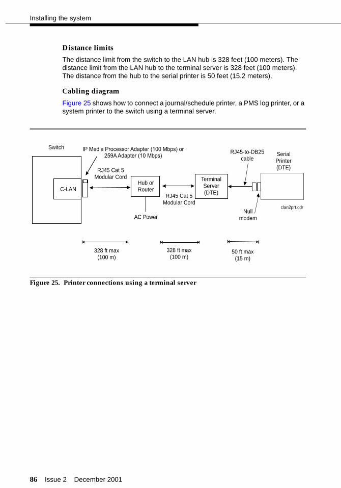
86 Issue 2 December 2001
Installing the system
Distance limits
The distance limit from the switch to the LAN hub is 328 feet (100 meters). The distance limit from the LAN hub to the terminal server is 328 feet (100 meters). The distance from the hub to the serial printer is 50 feet (15.2 meters).
Cabling diagram
Figure 25 shows how to connect a journal/schedule printer, a PMS log printer, or a system printer to the switch using a terminal server.
Figure 25. Printer connections using a terminal server
clan2prt.cdr
SerialPrinter(DTE)
C-LAN
Switch
Hub orRouter
328 ft max(100 m)
328 ft max(100 m)
AC Power
RJ45 Cat 5Modular Cord
RJ45 Cat 5Modular Cord
TerminalServer(DTE)
RJ45-to-DB25cable
50 ft max(15 m)
IP Media Processor Adapter (100 Mbps) or259A Adapter (10 Mbps)
Nullmodem

Issue 2 December 2001 87
Connecting the hospitality adjuncts
Printer connections using a data module
This section describes how you connect a serial printer to the switch using a data module.
Parts list
Each printer connection requires the following parts:
■ One digital communications protocol (DCP) port on the switch; the 8400B data module uses a TN2214 or TN2224 2-wire digital port, and the 7400A and 7400B data modules use a TN754C 4-wire digital port.
■ Standard cross-connect hardware
■ One D8W modular cord
■ One 8400B DCP data module optioned as shown on page 89, one 7400A DCP data module optioned as shown in Table 7 on Page 90, or one 7400B DCP data module optioned as shown on page 91
■ One DB9-to-DB25 transition cable when using the 8400B data module
■ One M25B cable (or equivalent 25-pin straight-through cable); see “Appendix A — Parts list” on page 286.
■ One Okidata Model ML321T printer (or equivalent).
Distance limits
The distance limit when connecting a data module to a TN2214 or TN2224 with 24 AWG wire is 3500 feet (1067 meters). The distance limit when connecting a data module to a TN754C is 5000 feet (1524 meters) with 24 AWG wire, and 4000 feet (1219 meters) with 26 AWG wire.
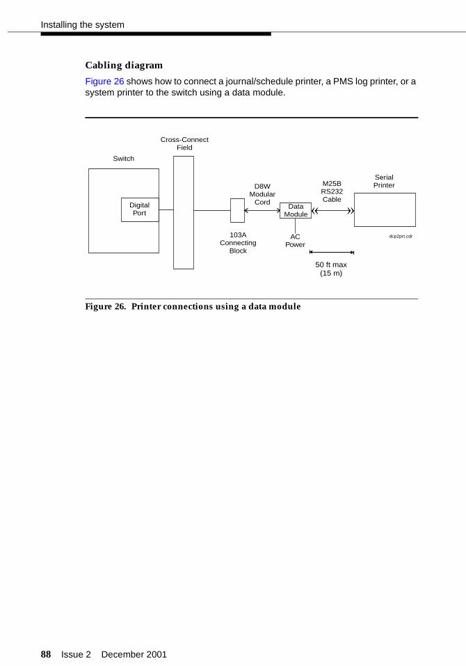
88 Issue 2 December 2001
Installing the system
Cabling diagram
Figure 26 shows how to connect a journal/schedule printer, a PMS log printer, or a system printer to the switch using a data module.
Figure 26. Printer connections using a data module
DigitalPort
Switch
DataModule
Cross-ConnectField
SerialPrinterM25B
RS232Cable
D8WModular
Cord
103AConnecting
Block
ACPower
»«
dcp2prt.cdr
50 ft max(15 m)

Issue 2 December 2001 89
Connecting the hospitality adjuncts
8400B options
The options on the 8400B must be set using an ASCII data terminal or a PC using a terminal emulation package. You must connect the data terminal or PC to the EIA interface connector on the back of the 8400B. For the journal/log printers, a subset of options must be changed. These options are changed using the AT command set. Use the following steps to set the options on the 8400B:
1. Set the speed on the data terminal or terminal emulation package to match the speed of the printer. By doing this, the speed on the 8400B will autobaud to match the correct speed.
2. From the data terminal or PC, type at . This automatically sets the speed and parity for the connection. The OK prompt should display.
3. Type the following commands as shown. (The character 0 is the number zero.) Before you press for each command, make sure that the command has been entered correctly. The e0 option on the last command turns off keyboard echo, which means that after you enter this command, any future keyboard entries will not be displayed, and the OK prompt is not displayed.
at&f (the OK prompt displays)ats24=1 (the OK prompt displays)at&c1&d2&s1s0=1 (the OK prompt displays)ate0q1&w0&y0&v
The &v portion of the last command displays the current set of options. Your screen should look something like this:
4. Disconnect the data terminal or PC from the 8400B.
5. Reconnect the unit as shown in Figure 26.
6. Cycle power on the 8400B (disconnect the line cord momentarily).
If your printer requires a different set of options, consult the 8400B Plus Data Module User’s Guide.
Enter
Enter
Enter
Enter
Enter
Enter
ACTIVE PROFILE:B1 E0 L2 M1 Q1 V1 X4 Y0 &C1 &D2 &G0 &J0 &L0 &P0 &Q0 &R0 &S1 &X0 &Y0S00:001 S01:000 S02:043 S03:013 S04:010 S05:008 S06:002 S07:060S08:002 S09:006 S10:014 S12:050 S14:ACH S16:00H S18:000 S21:70HS22:76H S23:1BH S24:01H S25:005 S26:001 S27:40H
STORED PROFILE 0:B1 E0 L2 M1 Q1 V1 X4 Y0 &C1 &D2 &G0 &J0 &L0 &P0 &Q0 &R0 &S1 &X0S00:001 S14:ACH S18:000 S21:70H S22:76H S23:1BH S24:01H S25:005S26:001 S27:40H
STORED PROFILE 1:B1 E1 L2 M1 Q0 V1 X4 Y0 &C0 &D0 &G0 &J0 &L0 &P0 &Q0 &R0 &S0 &X0S00:000 S14:AAH S18:000 S21:00H S22:76H S23:1BH S24:01H S25:005S26:001 S27:40H
TELEPHONE NUMBERS:
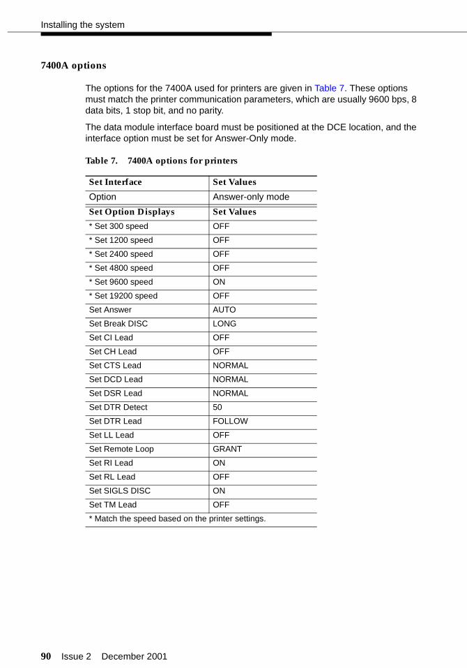
90 Issue 2 December 2001
Installing the system
7400A options
The options for the 7400A used for printers are given in Table 7. These options must match the printer communication parameters, which are usually 9600 bps, 8 data bits, 1 stop bit, and no parity.
The data module interface board must be positioned at the DCE location, and the interface option must be set for Answer-Only mode.
Table 7. 7400A options for printers
Set Interface Set Values
Option Answer-only mode
Set Option Displays Set Values
* Set 300 speed OFF
* Set 1200 speed OFF
* Set 2400 speed OFF
* Set 4800 speed OFF
* Set 9600 speed ON
* Set 19200 speed OFF
Set Answer AUTO
Set Break DISC LONG
Set CI Lead OFF
Set CH Lead OFF
Set CTS Lead NORMAL
Set DCD Lead NORMAL
Set DSR Lead NORMAL
Set DTR Detect 50
Set DTR Lead FOLLOW
Set LL Lead OFF
Set Remote Loop GRANT
Set RI Lead ON
Set RL Lead OFF
Set SIGLS DISC ON
Set TM Lead OFF
* Match the speed based on the printer settings.
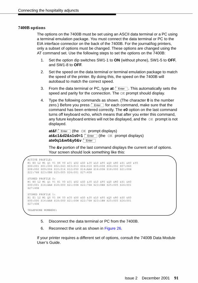
Issue 2 December 2001 91
Connecting the hospitality adjuncts
7400B options
The options on the 7400B must be set using an ASCII data terminal or a PC using a terminal emulation package. You must connect the data terminal or PC to the EIA interface connector on the back of the 7400B. For the journal/log printers, only a subset of options must be changed. These options are changed using the AT command set. Use the following steps to set the options on the 7400B:
1. Set the option dip switches SW1-1 to ON (without phone), SW1-5 to OFF, and SW1-8 to OFF.
2. Set the speed on the data terminal or terminal emulation package to match the speed of the printer. By doing this, the speed on the 7400B will autobaud to match the correct speed.
3. From the data terminal or PC, type at . This automatically sets the speed and parity for the connection. The OK prompt should display.
4. Type the following commands as shown. (The character 0 is the number zero.) Before you press for each command, make sure that the command has been entered correctly. The e0 option on the last command turns off keyboard echo, which means that after you enter this command, any future keyboard entries will not be displayed, and the OK prompt is not displayed.
at&f (the OK prompt displays)at&c1&d2&s1s0=1 (the OK prompt displays)ate0q1&w0&y0&v
The &v portion of the last command displays the current set of options. Your screen should look something like this:
5. Disconnect the data terminal or PC from the 7400B.
6. Reconnect the unit as shown in Figure 26.
If your printer requires a different set of options, consult the 7400B Data Module User’s Guide.
Enter
Enter
Enter
Enter
Enter
ACTIVE PROFILE:B1 E0 L2 M1 Q1 V1 X4 Y0 &C1 &D2 &G0 &J0 &L0 &P0 &Q0 &R0 &S1 &X0 &Y0S00:001 S01:000 S02:043 S03:013 S04:010 S05:008 S06:002 S07:060S08:002 S09:006 S10:014 S12:050 S14:AAH S16:00H S18:000 S21:00HS22:76H S23:0BH S25:005 S26:001 S27:40H
STORED PROFILE 0:B1 E0 L2 M1 Q1 V1 X1 Y0 &C1 &D2 &G0 &J0 &L0 &P0 &Q0 &R0 &S1 &X0S00:001 S14:AAH S18:000 S21:00H S22:76H S23:0BH S25:005 S26:001S27:40H
STORED PROFILE 1:B1 E1 L2 M1 Q0 V1 X4 Y0 &C0 &D0 &G0 &J0 &L0 &P0 &Q0 &R0 &S0 &X0S00:000 S14:AAH S18:000 S21:00H S22:76H S23:1BH S25:005 S26:001S27:40H
TELEPHONE NUMBERS:
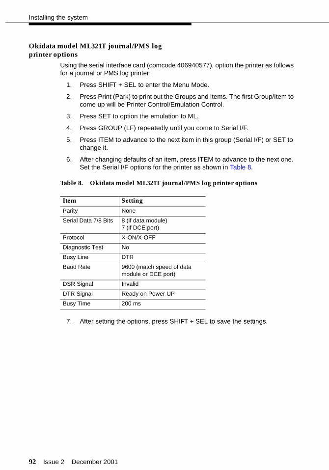
92 Issue 2 December 2001
Installing the system
Okidata model ML321T journal/PMS logprinter options
Using the serial interface card (comcode 406940577), option the printer as follows for a journal or PMS log printer:
1. Press SHIFT + SEL to enter the Menu Mode.
2. Press Print (Park) to print out the Groups and Items. The first Group/Item to come up will be Printer Control/Emulation Control.
3. Press SET to option the emulation to ML.
4. Press GROUP (LF) repeatedly until you come to Serial I/F.
5. Press ITEM to advance to the next item in this group (Serial I/F) or SET to change it.
6. After changing defaults of an item, press ITEM to advance to the next one. Set the Serial I/F options for the printer as shown in Table 8.
Table 8. Okidata model ML321T journal/PMS log printer options
7. After setting the options, press SHIFT + SEL to save the settings.
Item Setting
Parity None
Serial Data 7/8 Bits 8 (if data module)7 (if DCE port)
Protocol X-ON/X-OFF
Diagnostic Test No
Busy Line DTR
Baud Rate 9600 (match speed of data module or DCE port)
DSR Signal Invalid
DTR Signal Ready on Power UP
Busy Time 200 ms

Issue 2 December 2001 93
Connecting the hospitality adjuncts
Okidata model ML321T system printer options
Using the serial interface card (comcode 406940577), option the printer as follows for a system printer:
1. Press SHIFT + SEL to enter the Menu Mode.
2. Use the GROUP, ITEM, and SET keys to make changes:
■ Press GROUP until the group you wish to change appears in the first column.
■ Press ITEM until the item you wish to change appears in the second column.
■ Press SET until the setting you want appears in the third column.
3. Set the options for the printer as shown in Table 9.
Table 9. Okidata model ML321T system printer options
Group Item Setting
Printer Control Emulation Mode ML
Font Print Mode Utility
DRAFT Mode HSD
Pitch 12 CPI
Proportional No
Style Normal
Size Single
Symbol Sets Character Set Standard
Language Set American
Zero Character Slashed
Code Page USA
Clear Feed Line Spacing 8 LPI
Form Tear-Off Off
Skip Over Perforation No
Page Width 13.6”
Page Length 11”
Bottom Feed Line Spacing 6 LPI
Form Tear-Off Off
Skip Over Perforation No
Page Width 13.6”
Page Length 11”
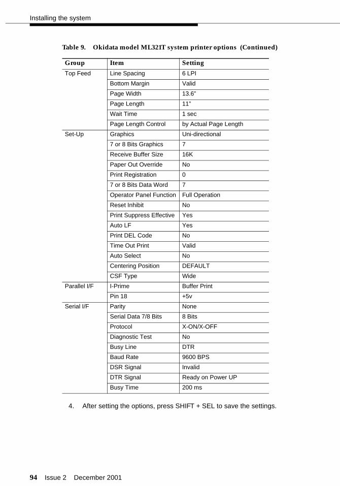
94 Issue 2 December 2001
Installing the system
4. After setting the options, press SHIFT + SEL to save the settings.
Top Feed Line Spacing 6 LPI
Bottom Margin Valid
Page Width 13.6”
Page Length 11”
Wait Time 1 sec
Page Length Control by Actual Page Length
Set-Up Graphics Uni-directional
7 or 8 Bits Graphics 7
Receive Buffer Size 16K
Paper Out Override No
Print Registration 0
7 or 8 Bits Data Word 7
Operator Panel Function Full Operation
Reset Inhibit No
Print Suppress Effective Yes
Auto LF Yes
Print DEL Code No
Time Out Print Valid
Auto Select No
Centering Position DEFAULT
CSF Type Wide
Parallel I/F I-Prime Buffer Print
Pin 18 +5v
Serial I/F Parity None
Serial Data 7/8 Bits 8 Bits
Protocol X-ON/X-OFF
Diagnostic Test No
Busy Line DTR
Baud Rate 9600 BPS
DSR Signal Invalid
DTR Signal Ready on Power UP
Busy Time 200 ms
Table 9. Okidata model ML321T system printer options (Continued)
Group Item Setting
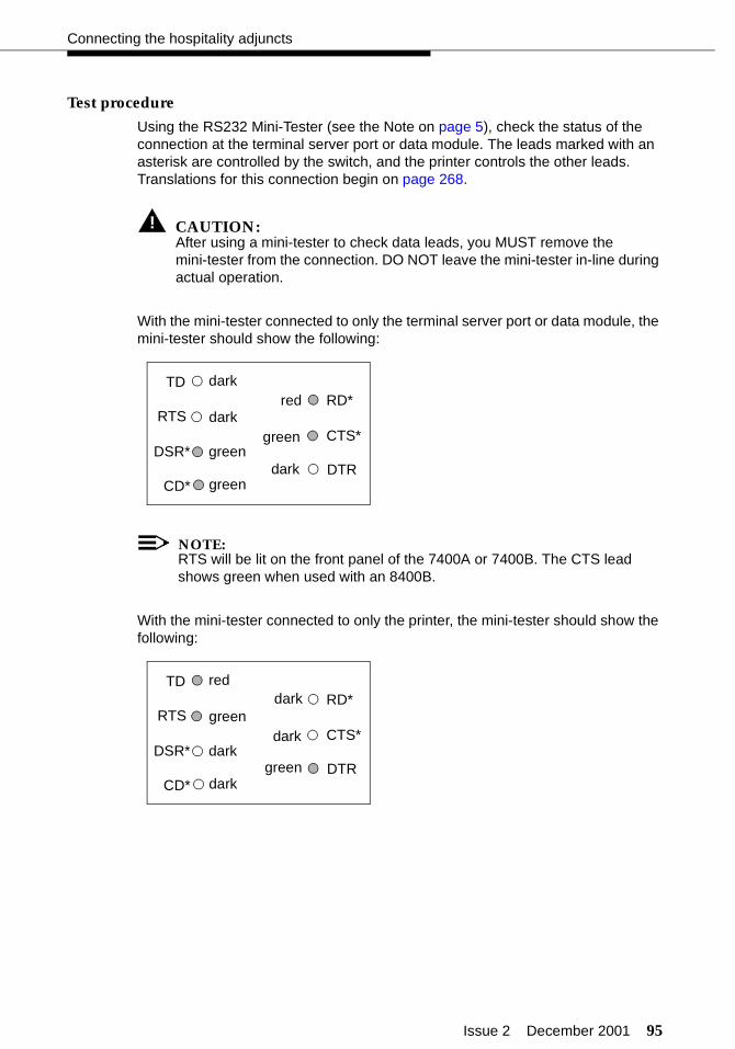
Issue 2 December 2001 95
Connecting the hospitality adjuncts
Test procedure
Using the RS232 Mini-Tester (see the Note on page 5), check the status of the connection at the terminal server port or data module. The leads marked with an asterisk are controlled by the switch, and the printer controls the other leads. Translations for this connection begin on page 268.
! CAUTION:After using a mini-tester to check data leads, you MUST remove the mini-tester from the connection. DO NOT leave the mini-tester in-line during actual operation.
With the mini-tester connected to only the terminal server port or data module, the mini-tester should show the following:
NOTE:RTS will be lit on the front panel of the 7400A or 7400B. The CTS lead shows green when used with an 8400B.
With the mini-tester connected to only the printer, the mini-tester should show the following:
TD
RTS
DTR
RD*
CTS*DSR*
CD*
reddark
darkgreen
green
greendark
TD
RTS
DTR
RD*
CTS*DSR*
CD*
darkred
greendark
dark
darkgreen
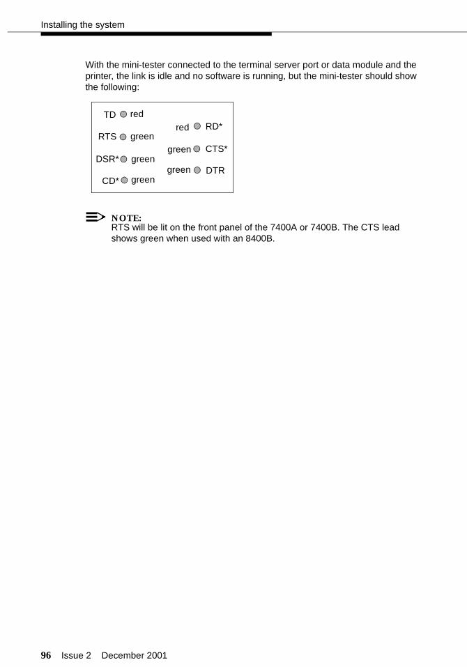
96 Issue 2 December 2001
Installing the system
With the mini-tester connected to the terminal server port or data module and the printer, the link is idle and no software is running, but the mini-tester should show the following:
NOTE:RTS will be lit on the front panel of the 7400A or 7400B. The CTS lead shows green when used with an 8400B.
TD
RTS
DTR
RD*
CTS*DSR*
CD*
red
green
green
green
red
green
green
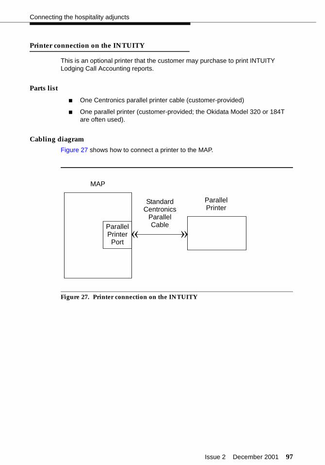
Issue 2 December 2001 97
Connecting the hospitality adjuncts
Printer connection on the INTUITY
This is an optional printer that the customer may purchase to print INTUITY Lodging Call Accounting reports.
Parts list
■ One Centronics parallel printer cable (customer-provided)
■ One parallel printer (customer-provided; the Okidata Model 320 or 184T are often used).
Cabling diagram
Figure 27 shows how to connect a printer to the MAP.
Figure 27. Printer connection on the INTUITY
ParallelPrinterPort
MAP
ParallelPrinter
StandardCentronics
ParallelCable
»«

98 Issue 2 December 2001
Installing the system
Switch-to-INADS connections
This connection is used for remote maintenance access to the switch from the Initialization and Administration System (INADS). The connectivity is different for the CMC switch than for the SCC or MCC switch.
NOTE:This INADS connection is typically installed only for installations in the United States. Contact your local support organization to see if INADS is required in your service area.
Parts list
SCC and MCC
■ The AUX connector on the SCC or MCC switch
■ One B25A 25-pair cable for cross-connections [connect the central office (CO) trunk to the last wire pair on this cable]
■ Standard cross-connect hardware
■ One CO trunk for dedicated access.
CMC
■ The Modem connector on the switch (this port is found on the Processor Interface Cable of the CMC hardware labeled as P2)
■ One M25A cable (or equivalent 25-pin straight-through cable)
■ One U.S. Robotics® Sportster® 33.6K modem
■ One RJ11 modular cord
■ One 103A connecting block
■ Standard cross-connect hardware
■ One CO trunk for dedicated access.
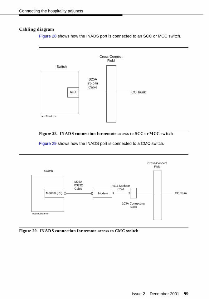
Issue 2 December 2001 99
Connecting the hospitality adjuncts
Cabling diagram
Figure 28 shows how the INADS port is connected to an SCC or MCC switch.
Figure 28. INADS connection for remote access to SCC or MCC switch
Figure 29 shows how the INADS port is connected to a CMC switch.
Figure 29. INADS connection for remote access to CMC switch
AUX
Switch
Cross-ConnectField
B25A25-pairCable
CO Trunk
aux2inad.cdr
Modem (P2) Modem
Switch
M25ARS232Cable
RJ11 ModularCord
103A ConnectingBlock
Cross-ConnectField
CO Trunk
««
modem2inad.cdr
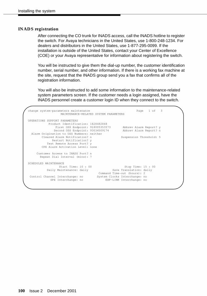
100 Issue 2 December 2001
Installing the system
INADS registration
After connecting the CO trunk for INADS access, call the INADS hotline to register the switch. For Avaya technicians in the United States, use 1-800-248-1234. For dealers and distributors in the United States, use 1-877-295-0099. If the installation is outside of the United States, contact your Center of Excellence (COE) or your Avaya representative for information about registering the switch.
You will be instructed to give them the dial-up number, the customer identification number, serial number, and other information. If there is a working fax machine at the site, request that the INADS group send you a fax that confirms all of the registration information.
You will also be instructed to add some information to the maintenance-related system parameters screen. If the customer needs a login assigned, have the INADS personnel create a customer login ID when they connect to the switch.
change system-parameters maintenance Page 1 of 3 MAINTENANCE-RELATED SYSTEM PARAMETERS
OPERATIONS SUPPORT PARAMETERS Product Identification: 1828482848 First OSS Endpoint: 918005353573 Abbrev Alarm Report? y Second OSS Endpoint: 93034509174 Abbrev Alarm Report? n Alarm Origination to OSS Numbers: neither Cleared Alarm Notification? n Suspension Threshold: 5 Restart Notification? y Test Remote Access Port? y CPE Alarm Activation Level: none
Customer Access to INADS Port? n Repeat Dial Interval (mins): 7
SCHEDULED MAINTENANCE Start Time: 10 : 00 Stop Time: 15 : 00 Daily Maintenance: daily Save Translation: daily Command Time-out (hours): 2 Control Channel Interchange: no System Clocks Interchange: no SPE Interchange: no EXP-LINK Interchange: no
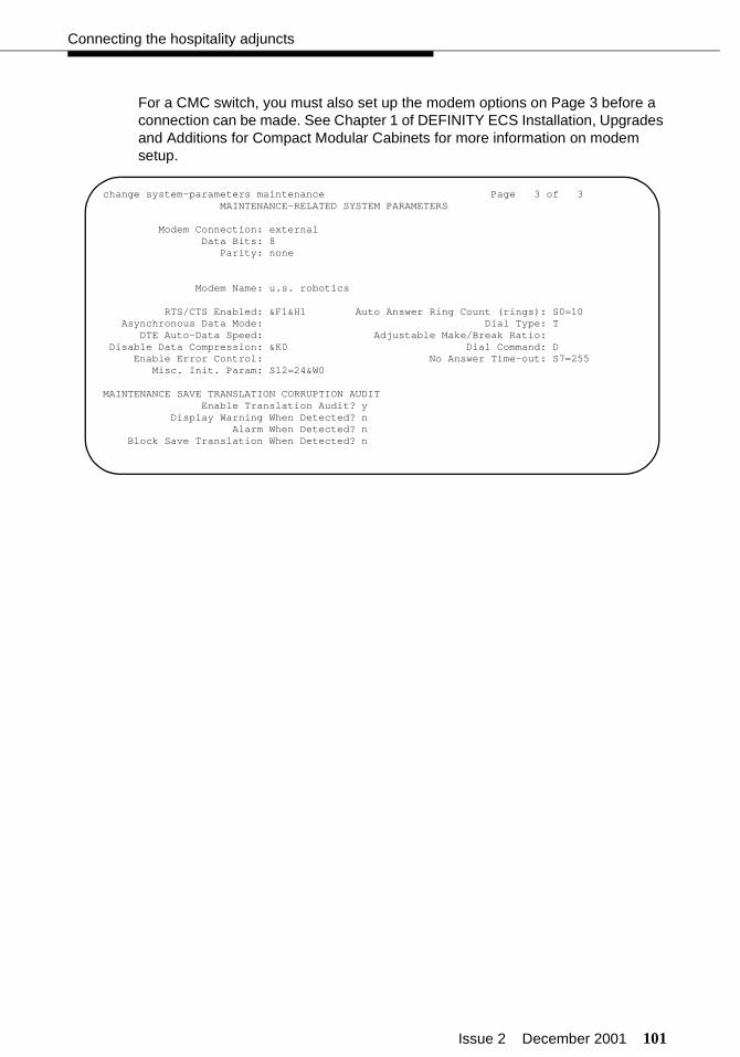
Issue 2 December 2001 101
Connecting the hospitality adjuncts
For a CMC switch, you must also set up the modem options on Page 3 before a connection can be made. See Chapter 1 of DEFINITY ECS Installation, Upgrades and Additions for Compact Modular Cabinets for more information on modem setup.
change system-parameters maintenance Page 3 of 3 MAINTENANCE-RELATED SYSTEM PARAMETERS
Modem Connection: external Data Bits: 8 Parity: none
Modem Name: u.s. robotics
RTS/CTS Enabled: &F1&H1 Auto Answer Ring Count (rings): S0=10 Asynchronous Data Mode: Dial Type: T DTE Auto-Data Speed: Adjustable Make/Break Ratio: Disable Data Compression: &K0 Dial Command: D Enable Error Control: No Answer Time-out: S7=255 Misc. Init. Param: S12=24&W0
MAINTENANCE SAVE TRANSLATION CORRUPTION AUDIT Enable Translation Audit? y Display Warning When Detected? n Alarm When Detected? n Block Save Translation When Detected? n
102 Issue 2 December 2001
Installing the system
MAP remote access connections
The INADS access is required, but the remote administration is optional. See the INTUITY documentation for more information about this remote access connection.
NOTE:If the INTUITY Remote Maintenance Board (RMB) is used, an external modem is not needed. See the INTUITY documentation for more information about using the Remote Maintenance Board.
Parts list
■ One or two Comsphere® 3820 modems (comcode 107560534) or locally-provided modems
■ One or two straight-through 9-pin to 25-pin transition cables (comcode 847106945)
■ One or two D25F cables (or equivalent straight-through cables) (comcode 105193668)
■ One or two D8W modular cords
■ Standard cross-connect hardware
■ One or two CO or DID trunks.

Issue 2 December 2001 103
Connecting the hospitality adjuncts
Cabling diagram
Figure 30 shows how to connect the Paradyne Comsphere 3820 modems to the MAP for remote access. This diagram also shows how the RMB is connected. If the RMB is used, the COM2 port cannot be used for any other application.
Figure 30. MAP remote access connections
COM1
COM2
LINE
RMB
MAP
OR
D25FRS232Cable
D25FRS232Cable
Cross-ConnectField
103AConnecting
Blocks
103AConnecting
Blocks
ForRemoteAdmin
(optional)
ForINADS
ForINADS
9-Pin to25-PinCable
9-Pin to25-PinCable
D8WModular
Cord
D8WModular
Cord
D8WModular
Cord
Comsphere3820
DTE
DTE
DIAL(RJ45)
DIAL(RJ45)»
»
»
»
»
»

104 Issue 2 December 2001
Installing the system
INADS alarm origination download
You can have the Comsphere 3820 or the RMB automatically configured by doing an alarm origination download. To start this download:
1. Use the Customer/Services Administration > Alarm Management command to display the following screen:
2. Enter the information as shown in the screen, using your actual Product ID and Alarm Destination phone number (the INADS number).
3. Once the options are correct, press to save the options. Press to continue.
4. Press to select the Chg Keys function.
5. Press to select the Test Alrm function.
6. Select the Execute Alarm Origination Test menu item.
7. Press y to start the test. The alarm origination download takes 2 to 5 minutes to complete.
8. After the download is complete, select the Review Latest Test Results menu item. The result message should say Alarm origination test successful.
For more details on this procedure, see the appropriate MAP installation document.
+-----------------------------------------------++ Alarm Management ++-----------------------------------------------+|Product ID 2200000000 || ||Alarm Destination 18005353573 || ||Alarm Origination ACTIVE || ||Alarm Level MAJOR || ||Alarm Suppression INACTIVE || ||Clear Alarm Notification ACTIVE |+-----------------------------------------------+
F3 Enter
F8
F1
Issue 2 December 2001 105
Translations and testing
The following sections contain translations and testing required to successfully administer the switch, the INTUITY Lodging Voice Messaging, and the INTUITY Lodging Call Accounting. Only the most important fields are highlighted with either required or suggested translations. Unless specified otherwise, the defaults provided are acceptable.
Most INTUITY Lodging installations will involve the MAP/5P hardware platform. In some cases, though, customers will have the MAP/40P or MAP/100P. The screens shown in this section apply for all of these platforms.
For installations with the InnOvation InnLine 2020, consult with the InnLine support personnel for administration.
NOTE:The screens shown in this section are examples only. Do not use the example equipment locations, extension numbers, access codes, and so on in your system. Use the translations provided by your software specialist or design specialist.
! CAUTION:While you are doing these translations on the switch, you should save your translations regularly using the save translation command. This could save you time retranslating if you lose power during installation. It takes about 10 minutes to process each translation save.

106 Issue 2 December 2001
Translations and testing
Translation checklist
Table 10 is a high-level checklist of the tasks required to translate a hospitality solution including the switch and the INTUITY system.
Table 10. Translation checklist
✔ Procedure
“Setting up the initial options” on page 13
“Miscellaneous translations” on page 107
“Switch-to-PMS link translations and testing” on page 189
“Switch-to-voice messaging translations and testing” on page 214
“Voice messaging-to-PMS translations and testing” on page 252
“Switch-to-call accounting translations and testing” on page 262
“INTUITY Lodging Call Accounting-to-PMS translations and testing” on page 267
“Printer translations (switch)” on page 268
“Parallel printer translations (INTUITY)” on page 278
“Customer logins (switch)” on page 278
“Customer logins (INTUITY)” on page 278
“Security notification (switch)” on page 279
“Saving translations (switch)” on page 280
“Creating a backup (INTUITY)” on page 280
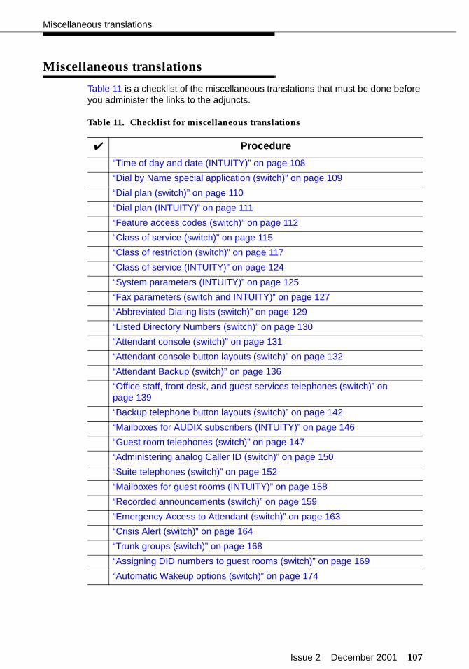
Issue 2 December 2001 107
Miscellaneous translations
Miscellaneous translations
Table 11 is a checklist of the miscellaneous translations that must be done before you administer the links to the adjuncts.
Table 11. Checklist for miscellaneous translations
✔ Procedure
“Time of day and date (INTUITY)” on page 108
“Dial by Name special application (switch)” on page 109
“Dial plan (switch)” on page 110
“Dial plan (INTUITY)” on page 111
“Feature access codes (switch)” on page 112
“Class of service (switch)” on page 115
“Class of restriction (switch)” on page 117
“Class of service (INTUITY)” on page 124
“System parameters (INTUITY)” on page 125
“Fax parameters (switch and INTUITY)” on page 127
“Abbreviated Dialing lists (switch)” on page 129
“Listed Directory Numbers (switch)” on page 130
“Attendant console (switch)” on page 131
“Attendant console button layouts (switch)” on page 132
“Attendant Backup (switch)” on page 136
“Office staff, front desk, and guest services telephones (switch)” on page 139
“Backup telephone button layouts (switch)” on page 142
“Mailboxes for AUDIX subscribers (INTUITY)” on page 146
“Guest room telephones (switch)” on page 147
“Administering analog Caller ID (switch)” on page 150
“Suite telephones (switch)” on page 152
“Mailboxes for guest rooms (INTUITY)” on page 158
“Recorded announcements (switch)” on page 159
“Emergency Access to Attendant (switch)” on page 163
“Crisis Alert (switch)” on page 164
“Trunk groups (switch)” on page 168
“Assigning DID numbers to guest rooms (switch)” on page 169
“Automatic Wakeup options (switch)” on page 174

108 Issue 2 December 2001
Translations and testing
Time of day and date (INTUITY)
For R4.4, use the Customer/Services Administration > System Management > UNIX® Management > UNIX Date and Time command to set the time and date on the INTUITY system. For R5 and later, use the UNIX Management > UNIX Date and Time command.
The switch time of day and date should already be set. See page 15 for information about setting the time of day and date on the switch if it is not correct. It is important that the switch and INTUITY system are set to the same time.
“Call Vectoring (switch)” on page 176
“Attendant Vectoring (switch)” on page 178
“Dial by Name (switch)” on page 179
“Trunk-to-Trunk Transfer (switch)” on page 182
“Terminal server for asynchronous links” on page 183
Table 11. Checklist for miscellaneous translations (Continued)
✔ Procedure
+---------------------------------------------------------++ UNIX Date and Time ++---------------------------------------------------------+| Date: April 22, 1999 || || Time: 3:39 || || AM/PM: PM || || Timezone: US/Mountain || || Is Daylight Savings Time used: YES |+---------------------------------------------------------+

Issue 2 December 2001 109
Miscellaneous translations
Dial by Name special application (switch)
Use the display system-parameters special-applications command to verify that the Dial by Name feature has been enabled. Dial by Name is a standard feature with Category B systems. It can be purchased and enabled as a special application for Category A systems. If the feature has not been enabled, call the technical support organization or your COE and have them dial in and enable the feature or apply a new license file.
display system-parameters special-applications Page 2 of 4SPECIAL APPLICATIONS
(SA7666) - COS Conference Tone Check? n(SA7880) - ASAI Internally Measured Data? n
(SA7779) - Enhanced DID Routing? n(SA7777) - Night Service on DID Trunk Groups? n
(SA7778) - Display UUI Information? n(SA7776) - Display Incoming Digits for ISDN Trunk Groups? n
(SA7852) - # and * in Vector Collect Step? none(SA7933) - Busy Tone with SAC and No Available Cvg Points? n
(SA7963) - Dial by Name? y(SA7990) - Service Observe Physical Set? n(SA7991) - Variable Length Account Code? n
(SA8052) - ISDN Redirecting Number? n(SA8077) - Russian Power Industry Feature? n
(SA7161) - NORTEL SL1 PRI and DMS Names Display? n(SA7578) - Integrated Directory Service over DCS? n
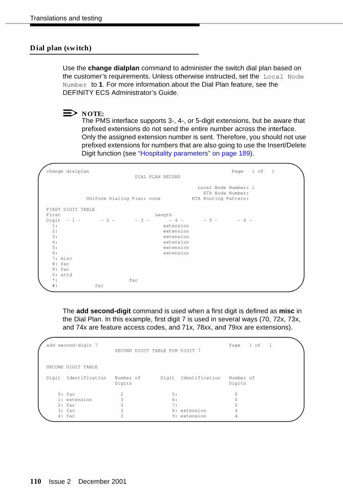
110 Issue 2 December 2001
Translations and testing
Dial plan (switch)
Use the change dialplan command to administer the switch dial plan based on the customer’s requirements. Unless otherwise instructed, set the Local Node Number to 1. For more information about the Dial Plan feature, see the DEFINITY ECS Administrator’s Guide.
NOTE:The PMS interface supports 3-, 4-, or 5-digit extensions, but be aware that prefixed extensions do not send the entire number across the interface. Only the assigned extension number is sent. Therefore, you should not use prefixed extensions for numbers that are also going to use the Insert/Delete Digit function (see “Hospitality parameters” on page 189).
The add second-digit command is used when a first digit is defined as misc in the Dial Plan. In this example, first digit 7 is used in several ways (70, 72x, 73x, and 74x are feature access codes, and 71x, 78xx, and 79xx are extensions).
change dialplan Page 1 of 1 DIAL PLAN RECORD
Local Node Number: 1 ETA Node Number:
Uniform Dialing Plan: none ETA Routing Pattern:
FIRST DIGIT TABLEFirst LengthDigit - 1 - - 2 - - 3 - - 4 - - 5 - - 6 - 1: extension 2: extension 3: extension 4: extension 5: extension 6: extension 7: misc 8: fac 9: fac 0: attd *: fac #: fac
add second-digit 7 Page 1 of 1SECOND DIGIT TABLE FOR DIGIT 7
SECOND DIGIT TABLE
Digit Identification Number of Digit Identification Number of Digits Digits
0: fac 2 5: 0 1: extension 3 6: 0 2: fac 3 7: 0 3: fac 3 8: extension 4 4: fac 3 9: extension 4
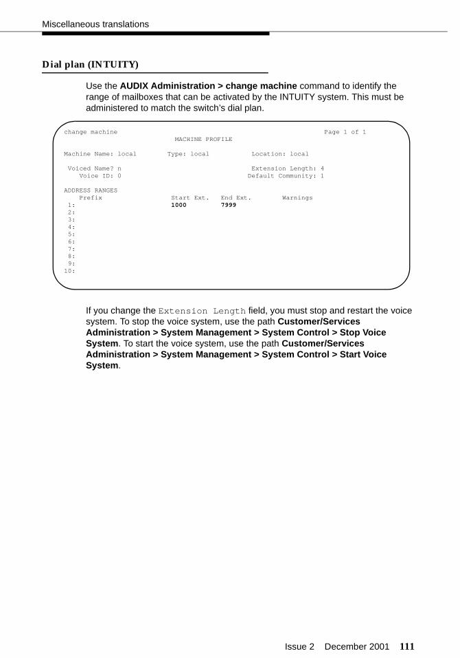
Issue 2 December 2001 111
Miscellaneous translations
Dial plan (INTUITY)
Use the AUDIX Administration > change machine command to identify the range of mailboxes that can be activated by the INTUITY system. This must be administered to match the switch’s dial plan.
If you change the Extension Length field, you must stop and restart the voice system. To stop the voice system, use the path Customer/Services Administration > System Management > System Control > Stop Voice System. To start the voice system, use the path Customer/Services Administration > System Management > System Control > Start Voice System.
change machine Page 1 of 1 MACHINE PROFILE
Machine Name: local Type: local Location: local
Voiced Name? n Extension Length: 4 Voice ID: 0 Default Community: 1
ADDRESS RANGES Prefix Start Ext. End Ext. Warnings 1: 1000 7999 2: 3: 4: 5: 6: 7: 8: 9:10:
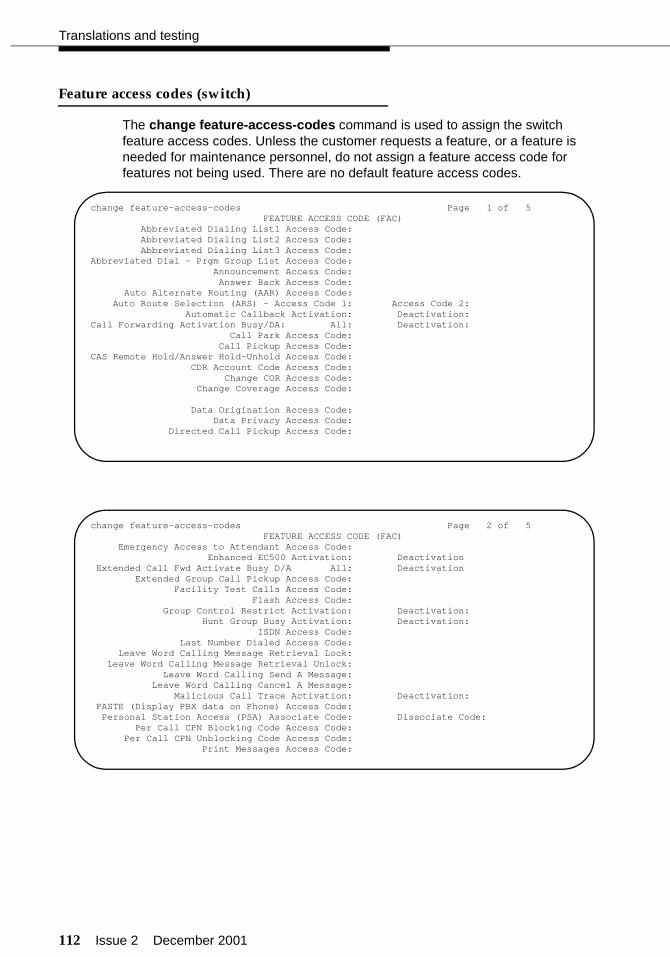
112 Issue 2 December 2001
Translations and testing
Feature access codes (switch)
The change feature-access-codes command is used to assign the switch feature access codes. Unless the customer requests a feature, or a feature is needed for maintenance personnel, do not assign a feature access code for features not being used. There are no default feature access codes.
change feature-access-codes Page 1 of 5 FEATURE ACCESS CODE (FAC) Abbreviated Dialing List1 Access Code: Abbreviated Dialing List2 Access Code: Abbreviated Dialing List3 Access Code: Abbreviated Dial - Prgm Group List Access Code:
Announcement Access Code: Answer Back Access Code:
Auto Alternate Routing (AAR) Access Code: Auto Route Selection (ARS) - Access Code 1: Access Code 2:
Automatic Callback Activation: Deactivation: Call Forwarding Activation Busy/DA: All: Deactivation: Call Park Access Code: Call Pickup Access Code: CAS Remote Hold/Answer Hold-Unhold Access Code: CDR Account Code Access Code:
Change COR Access Code:Change Coverage Access Code:
Data Origination Access Code: Data Privacy Access Code:
Directed Call Pickup Access Code:
change feature-access-codes Page 2 of 5 FEATURE ACCESS CODE (FAC)
Emergency Access to Attendant Access Code: Enhanced EC500 Activation: Deactivation
Extended Call Fwd Activate Busy D/A All: DeactivationExtended Group Call Pickup Access Code:
Facility Test Calls Access Code: Flash Access Code:
Group Control Restrict Activation: Deactivation:Hunt Group Busy Activation: Deactivation:
ISDN Access Code: Last Number Dialed Access Code: Leave Word Calling Message Retrieval Lock: Leave Word Calling Message Retrieval Unlock: Leave Word Calling Send A Message: Leave Word Calling Cancel A Message: Malicious Call Trace Activation: Deactivation:PASTE (Display PBX data on Phone) Access Code:Personal Station Access (PSA) Associate Code: Dissociate Code:
Per Call CPN Blocking Code Access Code:Per Call CPN Unblocking Code Access Code:
Print Messages Access Code:
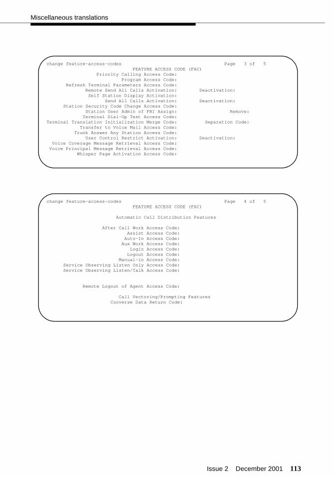
Issue 2 December 2001 113
Miscellaneous translations
change feature-access-codes Page 3 of 5 FEATURE ACCESS CODE (FAC)
Priority Calling Access Code: Program Access Code:
Refresh Terminal Parameters Access Code:Remote Send All Calls Activation: Deactivation:Self Station Display Activation:
Send All Calls Activation: Deactivation: Station Security Code Change Access Code:
Station User Admin of FBI Assign: Remove: Terminal Dial-Up Test Access Code: Terminal Translation Initialization Merge Code: Separation Code:
Transfer to Voice Mail Access Code: Trunk Answer Any Station Access Code: User Control Restrict Activation: Deactivation: Voice Coverage Message Retrieval Access Code: Voice Principal Message Retrieval Access Code:
Whisper Page Activation Access Code:
change feature-access-codes Page 4 of 5 FEATURE ACCESS CODE (FAC)
Automatic Call Distribution Features
After Call Work Access Code:Assist Access Code:
Auto-In Access Code:Aux Work Access Code:
Login Access Code:Logout Access Code:
Manual-in Access Code:Service Observing Listen Only Access Code:Service Observing Listen/Talk Access Code:
Remote Logout of Agent Access Code:
Call Vectoring/Prompting FeaturesConverse Data Return Code:
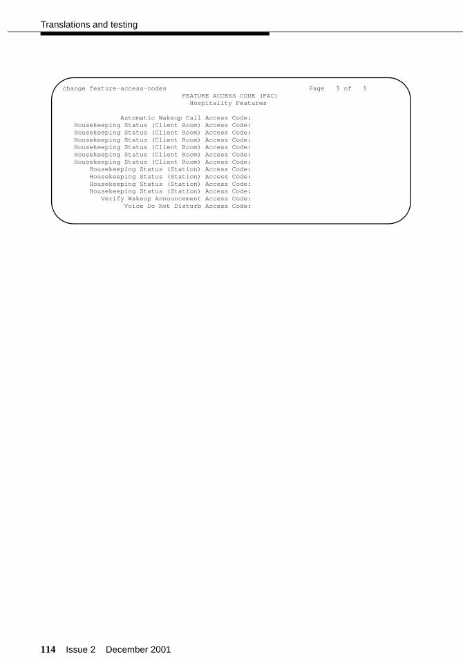
114 Issue 2 December 2001
Translations and testing
change feature-access-codes Page 5 of 5 FEATURE ACCESS CODE (FAC) Hospitality Features
Automatic Wakeup Call Access Code: Housekeeping Status (Client Room) Access Code: Housekeeping Status (Client Room) Access Code: Housekeeping Status (Client Room) Access Code: Housekeeping Status (Client Room) Access Code: Housekeeping Status (Client Room) Access Code: Housekeeping Status (Client Room) Access Code: Housekeeping Status (Station) Access Code: Housekeeping Status (Station) Access Code: Housekeeping Status (Station) Access Code: Housekeeping Status (Station) Access Code: Verify Wakeup Announcement Access Code: Voice Do Not Disturb Access Code:

Issue 2 December 2001 115
Miscellaneous translations
Class of service (switch)
You must make assignments to the Class of Service (COS) on the switch. A unique COS must be assigned to each of the following groups of users and equipment types on the switch:
■ Front desk, attendant console, and housekeeping (COS 0)
Telephones and attendant consoles used for check-in/check-out and Message Waiting Notification must have Console Permissions enabled in the COS. Designated stations used for housekeeping updates must have Console Permissions enabled in the COS.
■ Guest rooms (COS 1)
Guest rooms where Message Waiting Notification is used to light message lamps must have Client Room enabled in the COS.
■ Office staff (COS 2)
■ Guest services (COS 3)
■ AUDIX voice ports (4)
■ Data modules (COS 15)
! CAUTION:Do not assign Client Room COS of any of the following:
— Front desk telephones
— Housekeeping telephones
— Office staff telephones
— Guest services telephones
— DID telephone numbers (XDID and XDIDVIP station types)
If any of these are assigned to a Client Room COS, the name field on the station screen will not be saved in translations.
In addition, do not assign Console Permissions to any Class of Service except for the attendant consoles, backup telephones, and guest services telephones.

116 Issue 2 December 2001
Translations and testing
Use the change cos command to administer the COS. The following screen shows an example COS using the COS numbers given in the previous list. Features assigned with the COS must be approved by the customer.
change cos Page 1 of 1 CLASS OF SERVICE
0 1 2 3 4 5 6 7 8 9 10 11 12 13 14 15
Auto Callback y n y y n n n n n n n n n n n n Call Fwd-All Calls y n y y n y n n n n n n n n n n Data Privacy n y n n y n n n n n n n n n n y Priority Calling y n y y n n n n n n n n n n n n Console Permissions y n y y n n n n n n n n n n n n Off-hook Alert n y n n n n n n n n n n n n n n Client Room n y n n n n n n n n n n n n n n Restrict Call Fwd-Off Net y y y y y y y y y y y y y y y n Call Forwarding Busy/DA y n y y n n n n n n n n n n n n Personal Station Access (PSA) n n n n n n n n n n n n n n n n Extended Forwarding All n n n n n n n n n n n n n n n n Extended Forwarding B/DA n n n n n n n n n n n n n n n n Trk-to-Trk Transfer Override n n n n n n n n n n n n n n n n QSIG Call Offer Originations n n n n n n n n n n n n n n n nAutomatic Exclusion n n n n n n n n n n n n n n n n
Issue 2 December 2001 117
Miscellaneous translations
Class of restriction (switch)
You must create several Classes of Restriction (COR) to separate features and services among the different groups of users and equipment. The COR also controls calling permissions between CORs. That is, you can restrict one group of users from calling another group through the COR. The following is a list of these general COR groups (and the COR number used in the screen examples):
■ Guest rooms (COR 1)
■ Front desk, attendant console, and housekeeping (COR 2; similar setup as COR 1)
■ Office staff (COR 3; similar setup as COR 1)
■ Guest services (room service, kitchen, and so on) (COR 4)
■ Trunk groups (COR 20 and COR 21)
■ Vectors (COR 30)
■ INTUITY AUDIX voice ports and hunt groups (COR 35; similar setup as COR 30)
■ Netcon, processor interface, and data modules (COR 50).
The following screens show typical COR assignments for each of the groupings. Use the change cor command to administer the CORs. All levels of restriction must be agreed to by the customer.

118 Issue 2 December 2001
Translations and testing
This is an example COR for the guest rooms, front desk, housekeeping, and the office staff.
change cor 1 Page 1 of 4 CLASS OF RESTRICTION
COR Number: 1 COR Description: GUEST ROOMS
FRL: 7 APLT? yCan Be Service Observed? n Calling Party Restriction: none
Can Be A Service Observer? n Called Party Restriction: noneTime of Day Chart: 1 Forced Entry of Account Codes? n
Priority Queuing? n Direct Agent Calling? n Restriction Override: all Facility Access Trunk Test? n Restricted Call List? n Can Change Coverage? n
Access to MCT? y Fully Restricted Service? nGroup II Category For MFC: 7 Send ANI for MFE? n
MF ANI Prefix: Automatic Charge Display? nHear System Music on Hold? y PASTE (Display PBX Data on Phone)? n
Can Be Picked Up By Directed Call Pickup? nCan Use Directed Call Pickup? n
Omit Extension/Room Display: n Group Controlled Restriction: inactive
change cor 1 Page 2 of 4 CLASS OF RESTRICTION
MF Incoming Call Trace? nBrazil Collect Call Blocking? n
Block Transfer Display? nRemote Logout of Agent? n
change cor 1 Page 3 of 4 CLASS OF RESTRICTION
CALLING PERMISSION (Enter "y" to grant permission to call specified COR)
0? y 12? y 24? y 36? y 48? y 60? y 72? y 84? y 1? y 13? y 25? y 37? y 49? y 61? y 73? y 85? y 2? y 14? y 26? y 38? y 50? n 62? y 74? y 86? y 3? y 15? y 27? y 39? y 51? y 63? y 75? y 87? y 4? y 16? y 28? y 40? y 52? y 64? y 76? y 88? y 5? y 17? y 29? y 41? y 53? y 65? y 77? y 89? y
6? y 18? y 30? y 42? y 54? y 66? y 78? y 90? y7? y 19? y 31? y 43? y 55? y 67? y 79? y 91? y8? y 20? y 32? y 44? y 56? y 68? y 80? y 92? y9? y 21? y 33? y 45? y 57? y 69? y 81? y 93? y
10? y 22? y 34? y 46? y 58? y 70? y 82? y 94? y11? y 23? y 35? y 47? y 59? y 71? y 83? y 95? y

Issue 2 December 2001 119
Miscellaneous translations
This is an example COR for the guest services.
change cor 4 Page 1 of 4 CLASS OF RESTRICTION
COR Number: 4 COR Description: GUEST SERVICES
FRL: 3 APLT? yCan Be Service Observed? n Calling Party Restriction: none
Can Be A Service Observer? n Called Party Restriction: noneTime of Day Chart: 1 Forced Entry of Account Codes? n
Priority Queuing? n Direct Agent Calling? n Restriction Override: all Facility Access Trunk Test? n Restricted Call List? n Can Change Coverage? n
Access to MCT? y Fully Restricted Service? nGroup II Category For MFC: 7 Send ANI for MFE? n
MF ANI Prefix: Automatic Charge Display? nHear System Music on Hold? y PASTE (Display PBX Data on Phone)? n
Can Be Picked Up By Directed Call Pickup? nCan Use Directed Call Pickup? n
Omit Extension/Room Display: n Group Controlled Restriction: inactive
change cor 4 Page 2 of 4 CLASS OF RESTRICTION
MF Incoming Call Trace? nBrazil Collect Call Blocking? n
Block Transfer Display? nRemote Logout of Agent? n
change cor 4 Page 3 of 4 CLASS OF RESTRICTION
CALLING PERMISSION (Enter "y" to grant permission to call specified COR)
0? y 12? y 24? y 36? y 48? y 60? y 72? y 84? y 1? y 13? y 25? y 37? y 49? y 61? y 73? y 85? y 2? y 14? y 26? y 38? y 50? n 62? y 74? y 86? y 3? y 15? y 27? y 39? y 51? y 63? y 75? y 87? y 4? y 16? y 28? y 40? y 52? y 64? y 76? y 88? y 5? y 17? y 29? y 41? y 53? y 65? y 77? y 89? y
6? y 18? y 30? y 42? y 54? y 66? y 78? y 90? y7? y 19? y 31? y 43? y 55? y 67? y 79? y 91? y8? y 20? y 32? y 44? y 56? y 68? y 80? y 92? y9? y 21? y 33? y 45? y 57? y 69? y 81? y 93? y
10? y 22? y 34? y 46? y 58? y 70? y 82? y 94? y11? y 23? y 35? y 47? y 59? y 71? y 83? y 95? y
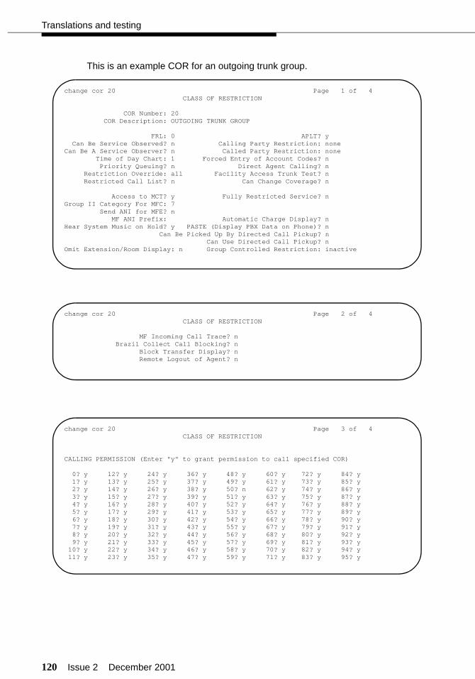
120 Issue 2 December 2001
Translations and testing
This is an example COR for an outgoing trunk group.
change cor 20 Page 1 of 4 CLASS OF RESTRICTION
COR Number: 20 COR Description: OUTGOING TRUNK GROUP
FRL: 0 APLT? yCan Be Service Observed? n Calling Party Restriction: none
Can Be A Service Observer? n Called Party Restriction: noneTime of Day Chart: 1 Forced Entry of Account Codes? n
Priority Queuing? n Direct Agent Calling? n Restriction Override: all Facility Access Trunk Test? n Restricted Call List? n Can Change Coverage? n
Access to MCT? y Fully Restricted Service? nGroup II Category For MFC: 7 Send ANI for MFE? n
MF ANI Prefix: Automatic Charge Display? nHear System Music on Hold? y PASTE (Display PBX Data on Phone)? n
Can Be Picked Up By Directed Call Pickup? nCan Use Directed Call Pickup? n
Omit Extension/Room Display: n Group Controlled Restriction: inactive
change cor 20 Page 2 of 4 CLASS OF RESTRICTION
MF Incoming Call Trace? nBrazil Collect Call Blocking? n
Block Transfer Display? nRemote Logout of Agent? n
change cor 20 Page 3 of 4 CLASS OF RESTRICTION
CALLING PERMISSION (Enter "y" to grant permission to call specified COR)
0? y 12? y 24? y 36? y 48? y 60? y 72? y 84? y 1? y 13? y 25? y 37? y 49? y 61? y 73? y 85? y 2? y 14? y 26? y 38? y 50? n 62? y 74? y 86? y 3? y 15? y 27? y 39? y 51? y 63? y 75? y 87? y 4? y 16? y 28? y 40? y 52? y 64? y 76? y 88? y 5? y 17? y 29? y 41? y 53? y 65? y 77? y 89? y
6? y 18? y 30? y 42? y 54? y 66? y 78? y 90? y7? y 19? y 31? y 43? y 55? y 67? y 79? y 91? y8? y 20? y 32? y 44? y 56? y 68? y 80? y 92? y9? y 21? y 33? y 45? y 57? y 69? y 81? y 93? y
10? y 22? y 34? y 46? y 58? y 70? y 82? y 94? y11? y 23? y 35? y 47? y 59? y 71? y 83? y 95? y
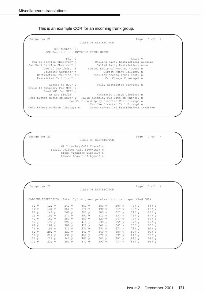
Issue 2 December 2001 121
Miscellaneous translations
This is an example COR for an incoming trunk group.
change cor 21 Page 1 of 4 CLASS OF RESTRICTION
COR Number: 21 COR Description: INCOMING TRUNK GROUP
FRL: 0 APLT? yCan Be Service Observed? n Calling Party Restriction: outward
Can Be A Service Observer? n Called Party Restriction: noneTime of Day Chart: 1 Forced Entry of Account Codes? n
Priority Queuing? n Direct Agent Calling? n Restriction Override: all Facility Access Trunk Test? n Restricted Call List? n Can Change Coverage? n
Access to MCT? y Fully Restricted Service? nGroup II Category For MFC: 7 Send ANI for MFE? n
MF ANI Prefix: Automatic Charge Display? nHear System Music on Hold? y PASTE (Display PBX Data on Phone)? n
Can Be Picked Up By Directed Call Pickup? nCan Use Directed Call Pickup? n
Omit Extension/Room Display: n Group Controlled Restriction: inactive
change cor 21 Page 2 of 4 CLASS OF RESTRICTION
MF Incoming Call Trace? nBrazil Collect Call Blocking? n
Block Transfer Display? nRemote Logout of Agent? n
change cor 21 Page 3 of 4 CLASS OF RESTRICTION
CALLING PERMISSION (Enter "y" to grant permission to call specified COR)
0? y 12? y 24? y 36? y 48? y 60? y 72? y 84? y 1? y 13? y 25? y 37? y 49? y 61? y 73? y 85? y 2? y 14? y 26? y 38? y 50? n 62? y 74? y 86? y 3? y 15? y 27? y 39? y 51? y 63? y 75? y 87? y 4? y 16? y 28? y 40? y 52? y 64? y 76? y 88? y 5? y 17? y 29? y 41? y 53? y 65? y 77? y 89? y
6? y 18? y 30? y 42? y 54? y 66? y 78? y 90? y7? y 19? y 31? y 43? y 55? y 67? y 79? y 91? y8? y 20? y 32? y 44? y 56? y 68? y 80? y 92? y9? y 21? y 33? y 45? y 57? y 69? y 81? y 93? y
10? y 22? y 34? y 46? y 58? y 70? y 82? y 94? y11? y 23? y 35? y 47? y 59? y 71? y 83? y 95? y
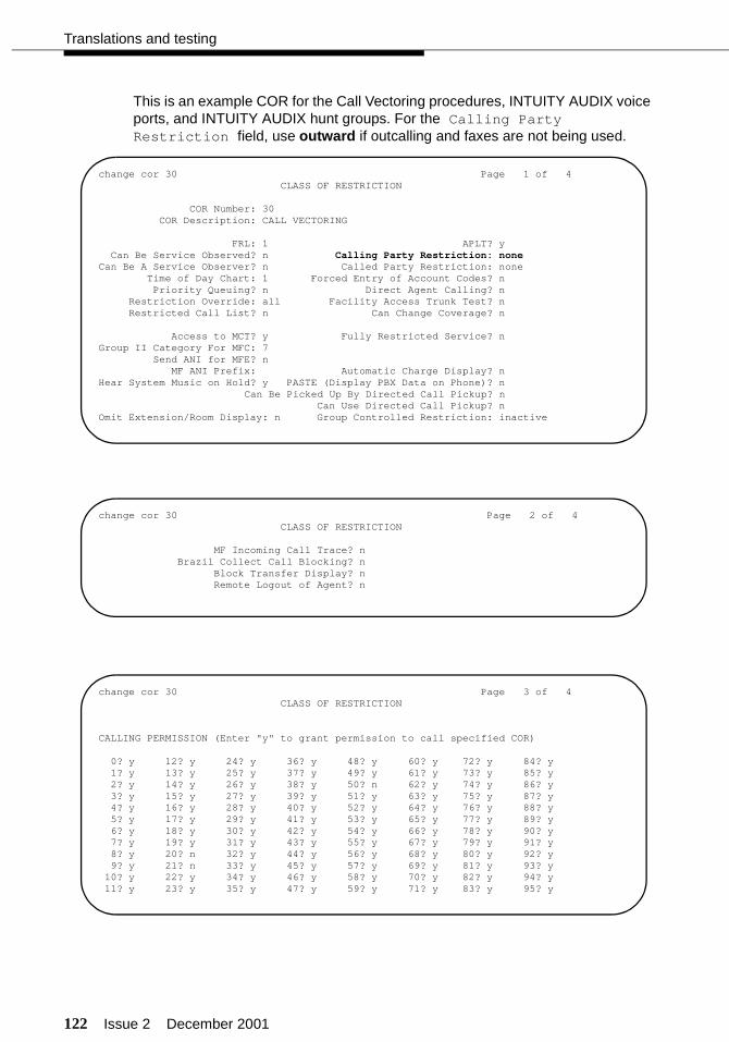
122 Issue 2 December 2001
Translations and testing
This is an example COR for the Call Vectoring procedures, INTUITY AUDIX voice ports, and INTUITY AUDIX hunt groups. For the Calling Party Restriction field, use outward if outcalling and faxes are not being used.
change cor 30 Page 1 of 4 CLASS OF RESTRICTION
COR Number: 30 COR Description: CALL VECTORING
FRL: 1 APLT? yCan Be Service Observed? n Calling Party Restriction: none
Can Be A Service Observer? n Called Party Restriction: noneTime of Day Chart: 1 Forced Entry of Account Codes? n
Priority Queuing? n Direct Agent Calling? n Restriction Override: all Facility Access Trunk Test? n Restricted Call List? n Can Change Coverage? n
Access to MCT? y Fully Restricted Service? nGroup II Category For MFC: 7 Send ANI for MFE? n
MF ANI Prefix: Automatic Charge Display? nHear System Music on Hold? y PASTE (Display PBX Data on Phone)? n
Can Be Picked Up By Directed Call Pickup? nCan Use Directed Call Pickup? n
Omit Extension/Room Display: n Group Controlled Restriction: inactive
change cor 30 Page 2 of 4 CLASS OF RESTRICTION
MF Incoming Call Trace? nBrazil Collect Call Blocking? n
Block Transfer Display? nRemote Logout of Agent? n
change cor 30 Page 3 of 4 CLASS OF RESTRICTION
CALLING PERMISSION (Enter "y" to grant permission to call specified COR)
0? y 12? y 24? y 36? y 48? y 60? y 72? y 84? y 1? y 13? y 25? y 37? y 49? y 61? y 73? y 85? y 2? y 14? y 26? y 38? y 50? n 62? y 74? y 86? y 3? y 15? y 27? y 39? y 51? y 63? y 75? y 87? y 4? y 16? y 28? y 40? y 52? y 64? y 76? y 88? y 5? y 17? y 29? y 41? y 53? y 65? y 77? y 89? y
6? y 18? y 30? y 42? y 54? y 66? y 78? y 90? y7? y 19? y 31? y 43? y 55? y 67? y 79? y 91? y8? y 20? n 32? y 44? y 56? y 68? y 80? y 92? y9? y 21? n 33? y 45? y 57? y 69? y 81? y 93? y
10? y 22? y 34? y 46? y 58? y 70? y 82? y 94? y11? y 23? y 35? y 47? y 59? y 71? y 83? y 95? y

Issue 2 December 2001 123
Miscellaneous translations
This is an example COR for the netcon, processor interface link, and data modules.
change cor 50 Page 1 of 4 CLASS OF RESTRICTION
COR Number: 50 COR Description: NETCON/PROC LINK/DATA MODULES
FRL: 7 APLT? yCan Be Service Observed? n Calling Party Restriction: none
Can Be A Service Observer? n Called Party Restriction: noneTime of Day Chart: 1 Forced Entry of Account Codes? n
Priority Queuing? n Direct Agent Calling? n Restriction Override: all Facility Access Trunk Test? n Restricted Call List? n Can Change Coverage? n
Access to MCT? y Fully Restricted Service? nGroup II Category For MFC: 7 Send ANI for MFE? n
MF ANI Prefix: Automatic Charge Display? nHear System Music on Hold? y PASTE (Display PBX Data on Phone)? n
Can Be Picked Up By Directed Call Pickup? nCan Use Directed Call Pickup? n
Omit Extension/Room Display: n Group Controlled Restriction: inactive
change cor 50 Page 2 of 4 CLASS OF RESTRICTION
MF Incoming Call Trace? nBrazil Collect Call Blocking? n
Block Transfer Display? nRemote Logout of Agent? n
change cor 50 Page 3 of 4 CLASS OF RESTRICTION
CALLING PERMISSION (Enter "y" to grant permission to call specified COR)
0? y 12? y 24? y 36? y 48? y 60? y 72? y 84? y 1? y 13? y 25? y 37? y 49? y 61? y 73? y 85? y 2? y 14? y 26? y 38? y 50? y 62? y 74? y 86? y 3? y 15? y 27? y 39? y 51? y 63? y 75? y 87? y 4? y 16? y 28? y 40? y 52? y 64? y 76? y 88? y 5? y 17? y 29? y 41? y 53? y 65? y 77? y 89? y
6? y 18? y 30? y 42? y 54? y 66? y 78? y 90? y7? y 19? y 31? y 43? y 55? y 67? y 79? y 91? y8? y 20? y 32? y 44? y 56? y 68? y 80? y 92? y9? y 21? y 33? y 45? y 57? y 69? y 81? y 93? y
10? y 22? y 34? y 46? y 58? y 70? y 82? y 94? y11? y 23? y 35? y 47? y 59? y 71? y 83? y 95? y
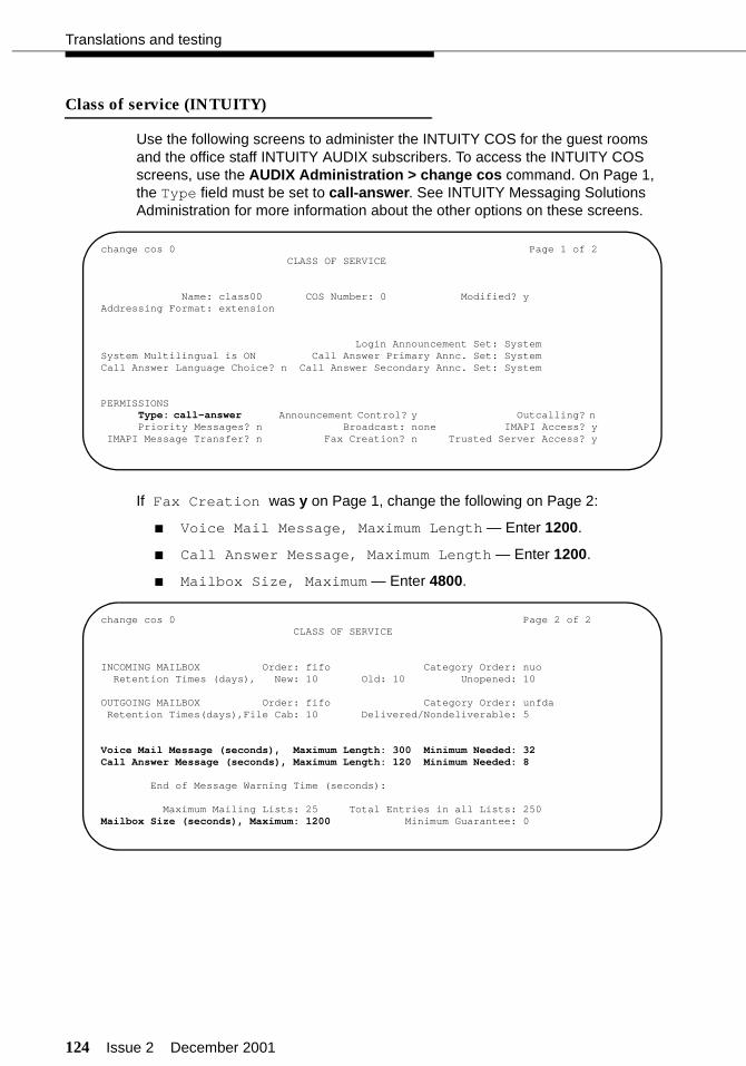
124 Issue 2 December 2001
Translations and testing
Class of service (INTUITY)
Use the following screens to administer the INTUITY COS for the guest rooms and the office staff INTUITY AUDIX subscribers. To access the INTUITY COS screens, use the AUDIX Administration > change cos command. On Page 1, the Type field must be set to call-answer. See INTUITY Messaging Solutions Administration for more information about the other options on these screens.
If Fax Creation was y on Page 1, change the following on Page 2:
■ Voice Mail Message, Maximum Length — Enter 1200.
■ Call Answer Message, Maximum Length — Enter 1200.
■ Mailbox Size, Maximum — Enter 4800.
change cos 0 Page 1 of 2 CLASS OF SERVICE
Name: class00 COS Number: 0 Modified? yAddressing Format: extension
Login Announcement Set: SystemSystem Multilingual is ON Call Answer Primary Annc. Set: SystemCall Answer Language Choice? n Call Answer Secondary Annc. Set: System
PERMISSIONSType: call-answer Announcement Control? y Outcalling? n Priority Messages? n Broadcast: none IMAPI Access? y
IMAPI Message Transfer? n Fax Creation? n Trusted Server Access? y
change cos 0 Page 2 of 2 CLASS OF SERVICE
INCOMING MAILBOX Order: fifo Category Order: nuo Retention Times (days), New: 10 Old: 10 Unopened: 10
OUTGOING MAILBOX Order: fifo Category Order: unfda Retention Times(days),File Cab: 10 Delivered/Nondeliverable: 5
Voice Mail Message (seconds), Maximum Length: 300 Minimum Needed: 32Call Answer Message (seconds), Maximum Length: 120 Minimum Needed: 8
End of Message Warning Time (seconds):
Maximum Mailing Lists: 25 Total Entries in all Lists: 250Mailbox Size (seconds), Maximum: 1200 Minimum Guarantee: 0
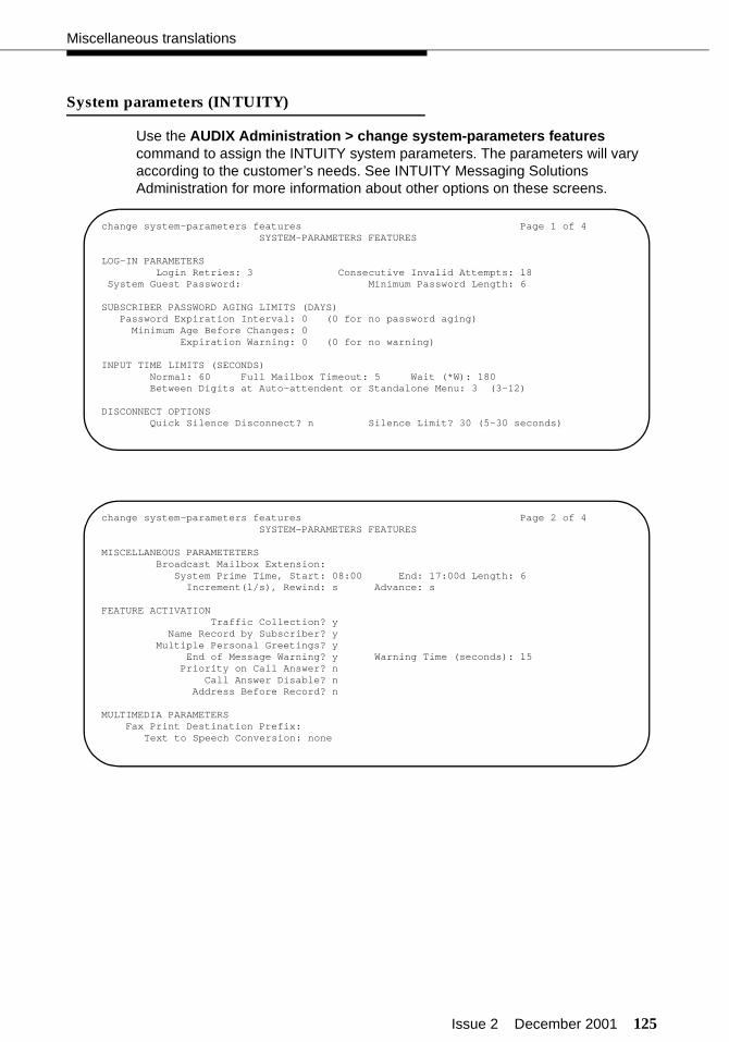
Issue 2 December 2001 125
Miscellaneous translations
System parameters (INTUITY)
Use the AUDIX Administration > change system-parameters features command to assign the INTUITY system parameters. The parameters will vary according to the customer’s needs. See INTUITY Messaging Solutions Administration for more information about other options on these screens.
change system-parameters features Page 1 of 4 SYSTEM-PARAMETERS FEATURES
LOG-IN PARAMETERS Login Retries: 3 Consecutive Invalid Attempts: 18 System Guest Password: Minimum Password Length: 6
SUBSCRIBER PASSWORD AGING LIMITS (DAYS) Password Expiration Interval: 0 (0 for no password aging) Minimum Age Before Changes: 0 Expiration Warning: 0 (0 for no warning)
INPUT TIME LIMITS (SECONDS) Normal: 60 Full Mailbox Timeout: 5 Wait (*W): 180 Between Digits at Auto-attendent or Standalone Menu: 3 (3-12)
DISCONNECT OPTIONS Quick Silence Disconnect? n Silence Limit? 30 (5-30 seconds)
change system-parameters features Page 2 of 4SYSTEM-PARAMETERS FEATURES
MISCELLANEOUS PARAMETETERS Broadcast Mailbox Extension: System Prime Time, Start: 08:00 End: 17:00d Length: 6 Increment(l/s), Rewind: s Advance: s
FEATURE ACTIVATIONTraffic Collection? y
Name Record by Subscriber? y Multiple Personal Greetings? y End of Message Warning? y Warning Time (seconds): 15 Priority on Call Answer? n Call Answer Disable? n Address Before Record? n
MULTIMEDIA PARAMETERSFax Print Destination Prefix:
Text to Speech Conversion: none

126 Issue 2 December 2001
Translations and testing
On Page 3 of the INTUITY system parameters, administer the following:
■ Transfer Type — Enter enhanced_cover_0. This will restrict the voice ports from calling trunk access codes assigned to the trunk groups.
■ Transfer Restriction — It is recommended that you enter subscribers to allow call transfers out of INTUITY AUDIX for calls to office staff subscribers only, and not calls to guest room telephones. Only technical support personnel can change this field to digits, and only when the customer has signed a letter to that effect.
■ Covering Extension — Enter the Listed Directory Number extension used for attendant-seeking calls (See page 130). If the Covering Extension is not administered, callers that “zero out” from the voice messaging system will hear “Operator not assigned,” and the caller cannot receive assistance.
change system-parameters features Page 3 of 4SYSTEM-PARAMETERS FEATURES
CALL TRANSFER OUT OF AUDIX Transfer Type: enhanced_cover_0 Transfer Restriction: subscribers Covering Extension: 2000
ANNOUNCEMENT SETS System: us-eng Administrative:
RESCHEDULING INCREMENTS FOR UNSUCCESSFUL MESSAGE DELIVERY Incr 1: 0 days 0 hrs 5 mins Incr 2: 0 days 0 hrs 15 mins Incr 3: 0 days 0 hrs 30 mins Incr 4: 0 days 1 hrs 0 mins Incr 5: 0 days 2 hrs 0 mins Incr 6: 0 days 6 hrs 0 mins Incr 7: 1 days 0 hrs 0 mins Incr 8: 2 days 0 hrs 0 mins Incr 9: 7 days 0 hrs 0 mins Incr10: 14 days 0 hrs 0 mins
change system-parameters features Page 4 of 4SYSTEM-PARAMETERS FEATURES
NETWORKING PARAMETETERS
Automatic Deletion of Non-administered Remote SubscribersDays without Activity: 0 Even If on a Mailing List? n
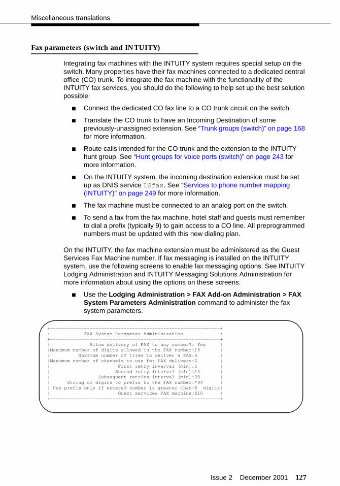
Issue 2 December 2001 127
Miscellaneous translations
Fax parameters (switch and INTUITY)
Integrating fax machines with the INTUITY system requires special setup on the switch. Many properties have their fax machines connected to a dedicated central office (CO) trunk. To integrate the fax machine with the functionality of the INTUITY fax services, you should do the following to help set up the best solution possible:
■ Connect the dedicated CO fax line to a CO trunk circuit on the switch.
■ Translate the CO trunk to have an Incoming Destination of some previously-unassigned extension. See “Trunk groups (switch)” on page 168 for more information.
■ Route calls intended for the CO trunk and the extension to the INTUITY hunt group. See “Hunt groups for voice ports (switch)” on page 243 for more information.
■ On the INTUITY system, the incoming destination extension must be set up as DNIS service LGfax. See “Services to phone number mapping (INTUITY)” on page 249 for more information.
■ The fax machine must be connected to an analog port on the switch.
■ To send a fax from the fax machine, hotel staff and guests must remember to dial a prefix (typically 9) to gain access to a CO line. All preprogrammed numbers must be updated with this new dialing plan.
On the INTUITY, the fax machine extension must be administered as the Guest Services Fax Machine number. If fax messaging is installed on the INTUITY system, use the following screens to enable fax messaging options. See INTUITY Lodging Administration and INTUITY Messaging Solutions Administration for more information about using the options on these screens.
■ Use the Lodging Administration > FAX Add-on Administration > FAX System Parameters Administration command to administer the fax system parameters.
+------------------------------------------------------------++ FAX System Parameter Administration ++------------------------------------------------------------+| Allow delivery of FAX to any number?: Yes ||Maximum number of digits allowed in the FAX number:15 || Naximum number of tries to deliver a FAX:5 ||Maximum number of channels to use for FAX delivery:2 || First retry inverval (min):5 || Second retry interval (min):10 || Subsequent retries interval (min):30 || String of digits to prefix to the FAX number:*99 || Use prefix only if entered number is greater than:6 digits|| Guest services FAX machine:810 |+------------------------------------------------------------+

128 Issue 2 December 2001
Translations and testing
■ Use the Lodging Administration > FAX Add-on Administration > Guest FAX Profile Administration command to administer the guest fax profile.
Billing considerations when forwarding faxes
Guests that have faxes in their mailboxes may wish to forward them to an external destination, often to a location that requires a toll call. In order for the hotel to bill the guest for the cost of this call, there are some translations you can do on the switch and the INTUITY system to make this work. This process is not completely automated, but it could help the hotel recover some call revenue.
1. Administer a feature access code for the CDR Account Code feature (for example, *49) and a feature access code for the ARS feature (usually 9).
2. Use the change system-parameters cdr command to set the CDR Account Code Length field to match the number of digits for extensions in the dial plan. See “CDR parameters (switch)” on page 262 for more information.
3. In the FAX System Parameter Administration screen on the INTUITY system, enter the CDR Account Code feature access code, the letter “e” (represents the guest room extension number), and the ARS feature access code in the String of digits to prefix to the FAX number field.
For this example, you would enter *49e9 in that field.
4. When the guest forwards a fax from his or her mailbox, he or she would dial the destination telephone number (9 for outside access is not needed).
5. The call generates a call record in which the guest room number appears in the account code data field of the call record.
6. The customer can now run call accounting reports based on the account code data field to see if there may be billing required for outgoing faxes. If the call is a toll call, the guest can be billed for the call.
For assistance in setting this up, contact the technical support center or your COE. See INTUITY Lodging Release 4 Administration or INTUITY Messaging Solutions Release 5 Documentation (CD) for more information about fax administration.
+-------------------------------------------------------------++ Guest FAX Profile Administration ++-------------------------------------------------------------+| Extension:733 || FAX mailbox for guest ON?:Yes || Maximum number of FAX messages:3 || Deliver FAX messages to any phone number?:Yes ||Keep FAX messages active in the mailbox after delivery?:No || Extension of the in-room FAX machine:345 |+-------------------------------------------------------------+
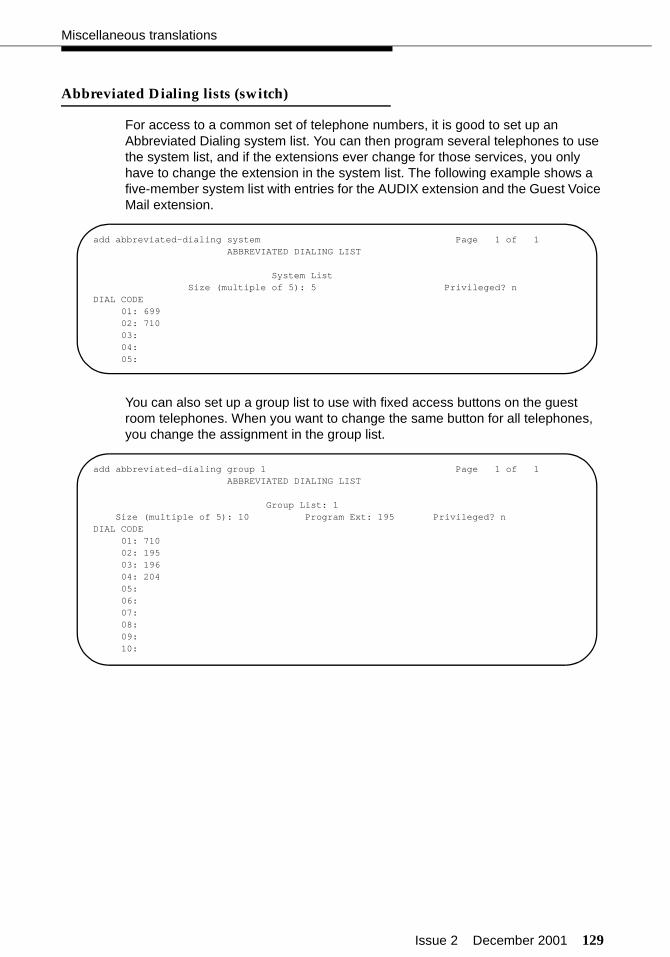
Issue 2 December 2001 129
Miscellaneous translations
Abbreviated Dialing lists (switch)
For access to a common set of telephone numbers, it is good to set up an Abbreviated Dialing system list. You can then program several telephones to use the system list, and if the extensions ever change for those services, you only have to change the extension in the system list. The following example shows a five-member system list with entries for the AUDIX extension and the Guest Voice Mail extension.
You can also set up a group list to use with fixed access buttons on the guest room telephones. When you want to change the same button for all telephones, you change the assignment in the group list.
add abbreviated-dialing system Page 1 of 1ABBREVIATED DIALING LIST
System ListSize (multiple of 5): 5 Privileged? n
DIAL CODE01: 69902: 71003:04:05:
add abbreviated-dialing group 1 Page 1 of 1ABBREVIATED DIALING LIST
Group List: 1Size (multiple of 5): 10 Program Ext: 195 Privileged? n
DIAL CODE01: 71002: 19503: 19604: 20405:06:07:08:09:10:

130 Issue 2 December 2001
Translations and testing
Listed Directory Numbers (switch)
Use the change listed-directory-number command to assign Listed Directory Numbers (LDNs) to the switch. These LDNs are usually the published numbers for the property and terminate at the attendant console.
change listed-directory-number Page 1 of 2LISTED DIRECTORY NUMBERS
Night Destination: 195
Ext Name TN1: 2000 12: 13: 14: 15: 16: 17: 18: 1
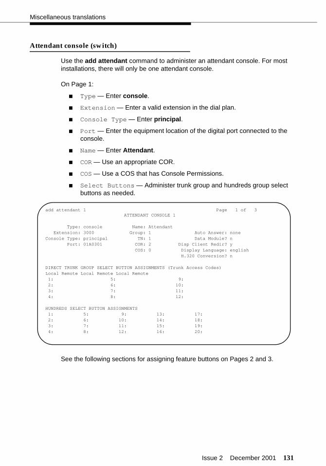
Issue 2 December 2001 131
Miscellaneous translations
Attendant console (switch)
Use the add attendant command to administer an attendant console. For most installations, there will only be one attendant console.
On Page 1:
■ Type — Enter console.
■ Extension — Enter a valid extension in the dial plan.
■ Console Type — Enter principal.
■ Port — Enter the equipment location of the digital port connected to the console.
■ Name — Enter Attendant.
■ COR — Use an appropriate COR.
■ COS — Use a COS that has Console Permissions.
■ Select Buttons — Administer trunk group and hundreds group select buttons as needed.
See the following sections for assigning feature buttons on Pages 2 and 3.
add attendant 1 Page 1 of 3ATTENDANT CONSOLE 1
Type: console Name: AttendantExtension: 3000 Group: 1 Auto Answer: none
Console Type: principal TN: 1 Data Module? nPort: 01A0301 COR: 2 Disp Client Redir? y
COS: 0 Display Language: englishH.320 Conversion? n
DIRECT TRUNK GROUP SELECT BUTTON ASSIGNMENTS (Trunk Access Codes)Local Remote Local Remote Local Remote1: 5: 9:2: 6: 10:3: 7: 11:4: 8: 12:
HUNDREDS SELECT BUTTON ASSIGNMENTS1: 5: 9: 13: 17:2: 6: 10: 14: 18:3: 7: 11: 15: 19:4: 8: 12: 16: 20:
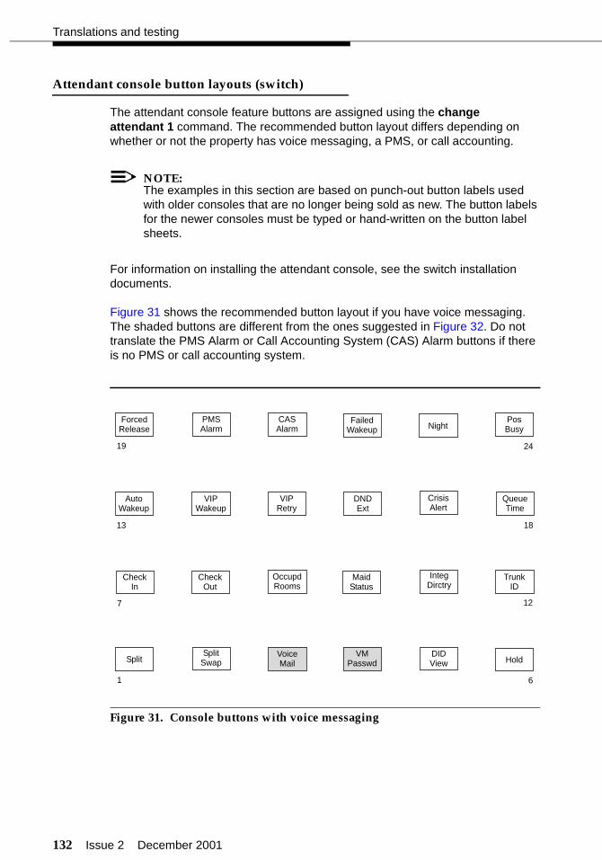
132 Issue 2 December 2001
Translations and testing
Attendant console button layouts (switch)
The attendant console feature buttons are assigned using the change attendant 1 command. The recommended button layout differs depending on whether or not the property has voice messaging, a PMS, or call accounting.
NOTE:The examples in this section are based on punch-out button labels used with older consoles that are no longer being sold as new. The button labels for the newer consoles must be typed or hand-written on the button label sheets.
For information on installing the attendant console, see the switch installation documents.
Figure 31 shows the recommended button layout if you have voice messaging. The shaded buttons are different from the ones suggested in Figure 32. Do not translate the PMS Alarm or Call Accounting System (CAS) Alarm buttons if there is no PMS or call accounting system.
Figure 31. Console buttons with voice messaging
FailedWakeup
AutoWakeup
VIPWakeup
DNDExt
DIDView
PMSAlarm
ForcedRelease
PosBusy
CASAlarm
QueueTime
CrisisAlert
VIPRetry
IntegDirctry
TrunkID
CheckIn
CheckOut
OccupdRooms
MaidStatus
HoldSplitSplit
Swap
Night
19 24
1813
127
1 6
VMPasswd
VoiceMail
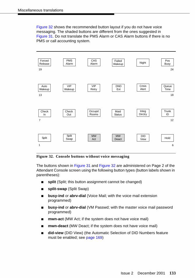
Issue 2 December 2001 133
Miscellaneous translations
Figure 32 shows the recommended button layout if you do not have voice messaging. The shaded buttons are different from the ones suggested in Figure 31. Do not translate the PMS Alarm or CAS Alarm buttons if there is no PMS or call accounting system.
Figure 32. Console buttons without voice messaging
The buttons shown in Figure 31 and Figure 32 are administered on Page 2 of the Attendant Console screen using the following button types (button labels shown in parentheses):
■ split (Split; this button assignment cannot be changed)
■ split-swap (Split Swap)
■ busy-ind or abrv-dial (Voice Mail; with the voice mail extension programmed)
■ busy-ind or abrv-dial (VM Passwd; with the master voice mail password programmed)
■ mwn-act (MW Act; if the system does not have voice mail)
■ mwn-deact (MW Deact; if the system does not have voice mail)
■ did-view (DID View) (the Automatic Selection of DID Numbers feature must be enabled; see page 169)
FailedWakeup
AutoWakeup
VIPWakeup
DNDExt
DIDView
PMSAlarm
ForcedRelease
PosBusy
CASAlarm
QueueTime
CrisisAlert
VIPRetry
IntegDirctry
TrunkID
CheckIn
CheckOut
OccupdRooms
MaidStatus
HoldSplitSplit
Swap
Night
19 24
1813
7 12
61
MWAct
MWDeact

134 Issue 2 December 2001
Translations and testing
■ hold (Hold)
■ check-in (Check In)
■ check-out (Check Out)
■ occ-rooms (Occupd Rooms)
■ maid-stat (Maid Status)
■ directory (Integ Dirctry)
■ trk-id (Trunk ID)
■ auto-wkup (Auto Wakeup)
■ vip-wakeup (VIP Wakeup)
■ vip-retry (VIP Retry)
■ ext-dn-dst (DND Ext)
■ crss-alert (Crisis Alert)
■ atd-qtime (Queue Time)
■ forced-rel (Forced Release; this button assignment cannot be changed)
■ pms-alarm (PMS Alarm)
■ cdr1-alrm (CAS Alarm)
■ aut-msg-wt (Failed Wakeup; administer the extension where failed Automatic Wakeup Calls are reported)
■ night-serv (Night)
■ pos-busy (Pos Busy)
There are other buttons you may want to add to the attendant console. If preprinted labels are not available for these features, you must create them on-site. These other buttons include the following:
■ abrv-dial (Controlled Restrictions assigned as an Abbreviated Dialing button). The Abbreviated Dialing button emulates dialing the feature access code followed by the desired restriction code, such as Outward Restriction.
For example, if the User Controlled Restriction Activate feature access code is *27, assign an Abbreviated Dialing button that dials *271. This automatically dials the feature access code and the code (1) for Outward Restriction. All the customer has to do now is enter the room number where the restriction is to be applied. Another button can be assigned for the deactivate code.
■ pr-awu-alm (Automatic Wakeup printer alarm)
■ pr-pms-alm (PMS printer alarm)
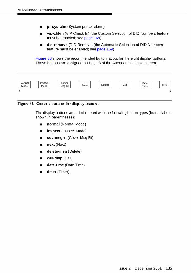
Issue 2 December 2001 135
Miscellaneous translations
■ pr-sys-alm (System printer alarm)
■ vip-chkin (VIP Check In) (the Custom Selection of DID Numbers feature must be enabled; see page 169)
■ did-remove (DID Remove) (the Automatic Selection of DID Numbers feature must be enabled; see page 169)
Figure 33 shows the recommended button layout for the eight display buttons. These buttons are assigned on Page 3 of the Attendant Console screen.
Figure 33. Console buttons for display features
The display buttons are administered with the following button types (button labels shown in parentheses):
■ normal (Normal Mode)
■ inspect (Inspect Mode)
■ cov-msg-rt (Cover Msg Rt)
■ next (Next)
■ delete-msg (Delete)
■ call-disp (Call)
■ date-time (Date Time)
■ timer (Timer)
NormalMode
InspectMode Delete Timer
CoverMsg Rt Next Call
1 8
DateTime
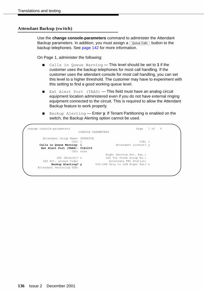
136 Issue 2 December 2001
Translations and testing
Attendant Backup (switch)
Use the change console-parameters command to administer the Attendant Backup parameters. In addition, you must assign a button to the backup telephones. See page 142 for more information.
On Page 1, administer the following:
■ Calls in Queue Warning — This level should be set to 1 if the customer uses the backup telephones for most call handling. If the customer uses the attendant console for most call handling, you can set this level to a higher threshold. The customer may have to experiment with this setting to find a good working queue level.
■ Ext Alert Port (TAAS) — This field must have an analog circuit equipment location administered even if you do not have external ringing equipment connected to the circuit. This is required to allow the Attendant Backup feature to work properly.
■ Backup Alerting — Enter y. If Tenant Partitioning is enabled on the switch, the Backup Alerting option cannot be used.
Queue Calls
change console-parameters Page 1 of 4 CONSOLE PARAMETERS
Attendant Group Name: OPERATOR COS: 1 COR: 1 Calls in Queue Warning: 1 Attendant Lockout? y Ext Alert Port (TAAS): 01A1216
CAS: none Night Service Act. Ext.:
IAS (Branch)? n IAS Tie Trunk Group No.:IAS Att. access Code: Alternate FRL Station:
Backup Alerting? y DID-LDN Only to LDN Night Ext? nAttendant Vectoring VDN:

Issue 2 December 2001 137
Miscellaneous translations
On Page 2, administer the following:
■ No Answer Timeout — This controls when ringing at the console will stop after a call is waiting in queue. When the timeout occurs, the console stops ringing, but the call can still be answered. A good value to begin with is 10.
■ Alerting — This controls the timeout limit before the console automatically goes into Night mode and Position Busy when calls are not answered. This is a good feature to administer in the situation in which the attendant takes a break or leaves at the end of the day and forgets to put the console into Night service. For example, if the No Answer Timeout field is set to 10 seconds, and the Alerting field is set to 10 seconds, the following occurs: a call rings at the console; after 10 seconds the console ringing shuts off; the call continues to queue for 10 seconds; then the console goes into Night mode and Position Busy. The call can now be answered from a backup telephone.
change console-parameters Page 2 of 4 CONSOLE PARAMETERS
TIMING Time Reminder on Hold (sec): 30 Return Call Timeout (sec): 60 Time in Queue Warning (sec): 15
INCOMING CALL REMINDERS No Answer Timeout (sec): 10 Alerting (sec): 10 Secondary Alert on Held Reminder Calls? y
ABBREVIATED DIALING List1: List2: List3: system
SAC Notification? n
COMMON SHARED EXTENSIONS Starting Extension: 670 Count: 3
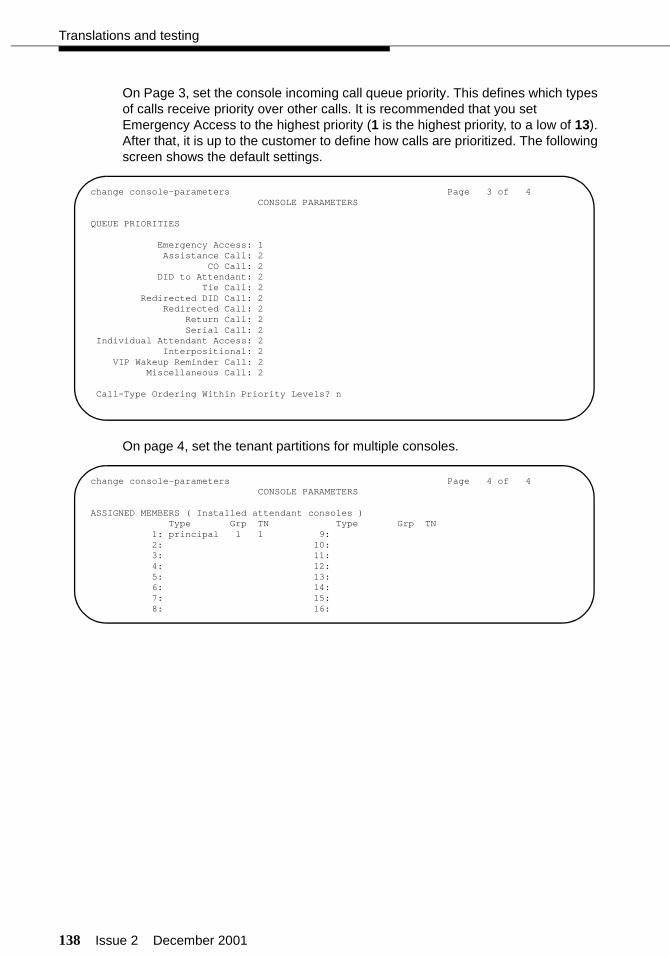
138 Issue 2 December 2001
Translations and testing
On Page 3, set the console incoming call queue priority. This defines which types of calls receive priority over other calls. It is recommended that you set Emergency Access to the highest priority (1 is the highest priority, to a low of 13). After that, it is up to the customer to define how calls are prioritized. The following screen shows the default settings.
On page 4, set the tenant partitions for multiple consoles.
change console-parameters Page 3 of 4 CONSOLE PARAMETERS
QUEUE PRIORITIES
Emergency Access: 1Assistance Call: 2
CO Call: 2DID to Attendant: 2
Tie Call: 2Redirected DID Call: 2
Redirected Call: 2Return Call: 2Serial Call: 2
Individual Attendant Access: 2Interpositional: 2
VIP Wakeup Reminder Call: 2Miscellaneous Call: 2
Call-Type Ordering Within Priority Levels? n
change console-parameters Page 4 of 4 CONSOLE PARAMETERS
ASSIGNED MEMBERS ( Installed attendant consoles )Type Grp TN Type Grp TN
1: principal 1 1 9:2: 10:3: 11:4: 12:5: 13:6: 14:7: 15:8: 16:

Issue 2 December 2001 139
Miscellaneous translations
Office staff, front desk, and guest servicestelephones (switch)
You must assign the telephones for the office staff, the front desk, guest room services, and other telephones located on the property. Use the add station command to administer these telephones. Depending on the model of the telephone, the screens show different fields. This example shows the model 6424 used as an attendant backup telephone.
NOTE:When the INTUITY Lodging Call Accounting package is first installed, the set of extensions and trunks administered on the switch is coordinated with Homisco. If extensions and trunks are added at a later date, Homisco must be notified so changes can be added to the call accounting package.
add station 195 Page 1 of 5 STATION
Extension: 195 Lock Messages? n BCC: 0 Type: 6424D+ Security Code: TN: 1 Port: 01A0201 Coverage Path 1: 1 COR: 2 Name: FRONT DESK Coverage Path 2: COS: 0
Hunt-to Station:
STATION OPTIONS Loss Group: 2 Personalized Ringing Pattern: 1 Data Option: none Message Lamp Ext: 195 Speakerphone: 2-way Mute Button Enabled? y Display Language: english Expansion Module? n
Media Complex Ext: IP SoftPhone? n
add station 195 Page 2 of 5 STATIONFEATURE OPTIONS LWC Reception: audix Auto Select Any Idle Appearance? n LWC Activation? n Coverage Msg Retrieval? y
LWC Log External Calls? n Auto Answer: none CDR Privacy? n Data Restriction? n Redirect Notification? y Idle Appearance Preference? n Per Button Ring Control? n Bridged Call Alerting? n Restrict Last Appearance? y Active Station Ringing: single
H.320 Conversion? n Per Station CPN - Send Calling Number?
Audible Message Waiting? nMWI Served User Type? n Display Client Redirection? n
Select Last Used Appearance? nCoverage After Forwarding? n
Emergency Location Ext:

140 Issue 2 December 2001
Translations and testing
add station 195 Page 3 of 5 STATION SITE DATA Room: Headset? n Jack: Speaker? n Cable: Mounting: d Floor: Cord Length: 0 Building: Set Color:
ABBREVIATED DIALING List1: personal 1 List2: List3: system
BUTTON ASSIGNMENTS 1: call-appr 5: autodial Number: 2: call-appr 6: autodial Number: 3: call-appr 7: autodial Number: 4: call-appr 8: autodial Number:
add station 195 Page 4 of 5 STATION
FEATURE BUTTON ASSIGNMENTS
9: atd-qcalls 10: vip-chkin11: did-remove12: aut-msg-wt Ext: 699 13: auto-wkup 14: ext-dn-dst 15: check-in 16: check-out 17: did-view18: mwn-act 19: mwn-deact 20: 21: pms-alarm22: cdr1-alrm23: aut-msg-wt Ext: 39924: autodial Number: *271

Issue 2 December 2001 141
Miscellaneous translations
add station 195 Page 5 of 5 STATION
SOFTKEY BUTTON ASSIGNMENTS
1: directory 2: drop 3: int-aut-an 4: timer 5: priority 6: auto-cback 7: abr-prog 8: abr-spchar Char: ~p 9: lwc-store10: ringer-off11: btn-view12: admin

142 Issue 2 December 2001
Translations and testing
Backup telephone button layouts (switch)
The telephones used for the Attendant Backup feature should have several of the same buttons you would assign to the attendant console. These are assigned using the change station XXXX command, where the XXXX is the extension number. The following is a list of the recommended feature buttons:
■ Attendant Queue Calls (atd-qcalls) (this button is required for the Attendant Backup feature)
■ Attendant Call Pickup (this is an autodial button that is programmed with the TAAS feature access code; the TAAS code is used to answer the Attendant Backup calls)
■ Attendant time in queue (atd-qtime)
■ Do Not Disturb - Extension (ext-dn-dst)
■ Automatic Wakeup (auto-wkup)
■ aut-msg-wt (administer the extension where failed Automatic Wakeup Calls are reported)
■ Night Service (night-serv) (only one backup telephone can have a Night Service button)
■ Ringer Cutoff (ringer-off)
■ Check-In (check-in)
■ Check-Out (check-out)
■ VIP Check-In (vip-chkin)
■ DID View (did-view) (the Automatic or Custom Selection of DID Numbers features must be enabled; see page 169)
■ DID Remove (did-remove) (the Automatic or Custom Selection of DID Numbers features must be enabled; see page 169)
■ Message Waiting Activation (mwn-act; if the system does not have voice mail)
■ Message Waiting Deactivation (mwn-deact; if the system does not have voice mail)
■ Busy Indication for the attendant console extension and any other backup telephones (busy-ind)
■ PMS Alarm (pms-alarm)
■ CAS Alarm (cdr1-alarm)
In addition, make sure that the backup telephone’s class of service has console permissions assigned (change cos).
Issue 2 December 2001 143
Miscellaneous translations
Figure 34, Figure 35, and Figure 36 show a typical setup if you had three telephones used as backups to the attendant console. The recommended primary backup telephone is the model 6424. The second and third backup telephones could be a model 6408. In this example, actual extension numbers are not given. Extension 1 represents the published front desk telephone number. Extensions 2 and 3 are nonpublished numbers known only to the hotel office staff. In this example, there are call appearances or bridged appearances of Extension 1 on all telephones, plus each telephone has at least one other extension that can be accessed as needed. With this arrangement, it makes it easy for front desk staff to answer a call at one telephone, put the call on hold, and pick up the call from another telephone.
When using the 8434 and 8410 telephones, adjust these recommended layouts to fit the button layouts available with those telephones.
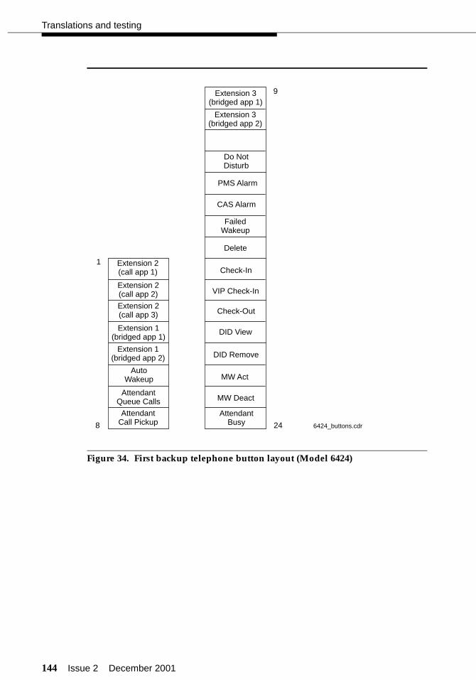
144 Issue 2 December 2001
Translations and testing
Figure 34. First backup telephone button layout (Model 6424)
Extension 1(bridged app 1)
Extension 1(bridged app 2)
Extension 2(call app 3)
Extension 2(call app 1)
Extension 3(bridged app 1)
Extension 3(bridged app 2)
Extension 2(call app 2)
AutoWakeup
AttendantCall Pickup
AttendantQueue Calls
Do NotDisturb
PMS Alarm
CAS Alarm
FailedWakeup
1
8 24
9
Delete
Check-In
Check-Out
DID View
MW Act
MW Deact
AttendantBusy 6424_buttons.cdr
DID Remove
VIP Check-In

Issue 2 December 2001 145
Miscellaneous translations
Figure 35. Second backup telephone button layout (Model 6408)
Figure 36. Third backup telephone button layout (Model 6408)
Extension 1(call app 1)
Extension 1(call app 2)
Extension 1(call app 3)
Extension 2(bridged app 2)
Extension 2(bridged app 1)
AutoWakeup
1
8
AttendantCall Pickup
AttendantQueue Calls
Extension 1(bridged app 1)
Extension 1(bridged app 2)
Extension 1(bridged app 3)
Extension 3(call app 1)
Extension 3(call app 2)
AutoWakeup
1
8
AttendantCall Pickup
AttendantQueue Calls
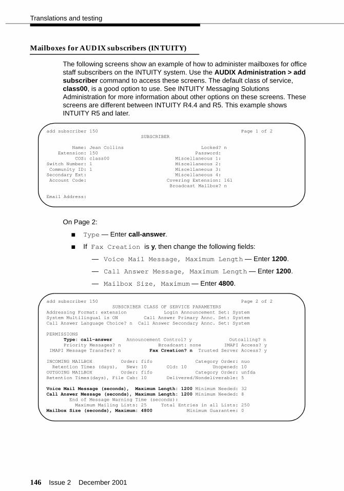
146 Issue 2 December 2001
Translations and testing
Mailboxes for AUDIX subscribers (INTUITY)
The following screens show an example of how to administer mailboxes for office staff subscribers on the INTUITY system. Use the AUDIX Administration > add subscriber command to access these screens. The default class of service, class00, is a good option to use. See INTUITY Messaging Solutions Administration for more information about other options on these screens. These screens are different between INTUITY R4.4 and R5. This example shows INTUITY R5 and later.
On Page 2:
■ Type — Enter call-answer.
■ If Fax Creation is y, then change the following fields:
— Voice Mail Message, Maximum Length — Enter 1200.
— Call Answer Message, Maximum Length — Enter 1200.
— Mailbox Size, Maximum — Enter 4800.
add subscriber 150 Page 1 of 2 SUBSCRIBER
Name: Jean Collins Locked? n Extension: 150 Password: COS: class00 Miscellaneous 1:Switch Number: 1 Miscellaneous 2: Community ID: 1 Miscellaneous 3:Secondary Ext: Miscellaneous 4:Account Code: Covering Extension: 161
Broadcast Mailbox? n
Email Address:
add subscriber 150 Page 2 of 2 SUBSCRIBER CLASS OF SERVICE PARAMETERSAddressing Format: extension Login Announcement Set: SystemSystem Multilingual is ON Call Answer Primary Annc. Set: SystemCall Answer Language Choice? n Call Answer Secondary Annc. Set: System
PERMISSIONSType: call-answer Announcement Control? y Outcalling? n Priority Messages? n Broadcast: none IMAPI Access? y
IMAPI Message Transfer? n Fax Creation? n Trusted Server Access? y
INCOMING MAILBOX Order: fifo Category Order: nuo Retention Times (days), New: 10 Old: 10 Unopened: 10OUTGOING MAILBOX Order: fifo Category Order: unfdaRetention Times(days), File Cab: 10 Delivered/Nondeliverable: 5
Voice Mail Message (seconds), Maximum Length: 1200 Minimum Needed: 32Call Answer Message (seconds), Maximum Length: 1200 Minimum Needed: 8 End of Message Warning Time (seconds): Maximum Mailing Lists: 25 Total Entries in all Lists: 250Mailbox Size (seconds), Maximum: 4800 Minimum Guarantee: 0

Issue 2 December 2001 147
Miscellaneous translations
Guest room telephones (switch)
Use the add station command to add guest room telephones. Once you have created one telephone, use the duplicate command to create the rest of the guest rooms since all rooms usually have the same features, coverage path, COS, and COR. The Message Waiting Indicator is hardware-dependent and must match the type of message waiting lamps on the guest telephones. This can vary from room to room. The Message Lamp Extension field must match the extension of the guest room.
NOTE:There are two features that affect the administration of guest rooms: Caller ID Telephones and Suite Telephones. If administering a room phone that has a caller ID, see also “Administering analog Caller ID (switch)” on page 150. If administering a guest room that is part of a suite, see also “Suite telephones (switch)” on page 152.
add station 107 Page 1 of 3 STATION
Extension: 107 Lock Messages? n BCC: 0 Type: 2500 Security Code: TN: 1 Port: 01A0201 Coverage Path 1: 1 COR: 1 Name: Coverage Path 2: COS: 1
Hunt-to Station: Tests? y
STATION OPTIONSLoss Group: 1 Message Waiting Indicator: led
Off Premise Station? n Message Lamp Ext: 107
add station 107 Page 2 of 3 STATIONFEATURE OPTIONS LWC Reception: audix LWC Activation? n Coverage Msg Retrieval? n
LWC Log External Calls? n Auto Answer: noneCDR Privacy? n Data Restriction? y
Redirect Notification? y Call Waiting Indication? nPer Button Ring Control? n Att. Call Waiting Indication? n
Bridged Call Alerting? n Distinctive Audible Alerting? nSwitchhook Flash? y Adjunct Supervision? n
Ignore Rotary Digits? nH.320 Conversion? n Per Station CPN - Send Calling Number?
Audible Message Waiting? nMWI Served User Type? n
Coverage After Forwarding? s
Emergency Location Ext:
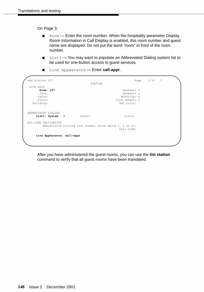
148 Issue 2 December 2001
Translations and testing
On Page 3:
■ Room — Enter the room number. When the hospitality parameter Display Room Information in Call Display is enabled, this room number and guest name are displayed. Do not put the word “room” in front of the room number.
■ List1 — You may want to populate an Abbreviated Dialing system list to be used for one-button access to guest services.
■ Line Appearance — Enter call-appr.
After you have administered the guest rooms, you can use the list station command to verify that all guest rooms have been translated.
add station 107 Page 3 of 3 STATION SITE DATA Room: 107 Headset? n Jack: Speaker? n Cable: Mounting: d Floor: Cord Length: 0 Building: Set Color:
ABBREVIATED DIALING List1: System 1 List2: List3:
HOT LINE DESTINATION Abbreviated Dialing List Number (From above 1, 2 or 3): Dial Code:
Line Appearance: call-appr
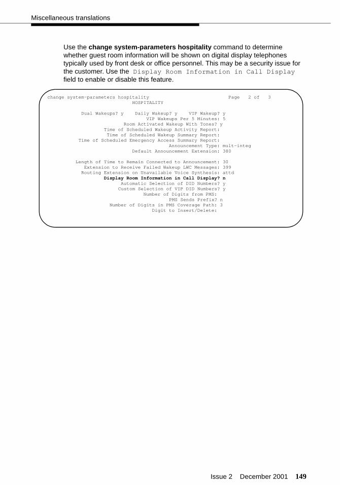
Issue 2 December 2001 149
Miscellaneous translations
Use the change system-parameters hospitality command to determine whether guest room information will be shown on digital display telephones typically used by front desk or office personnel. This may be a security issue for the customer. Use the Display Room Information in Call Display field to enable or disable this feature.
change system-parameters hospitality Page 2 of 3 HOSPITALITY
Dual Wakeups? y Daily Wakeup? y VIP Wakeup? yVIP Wakeups Per 5 Minutes: 5
Room Activated Wakeup With Tones? y Time of Scheduled Wakeup Activity Report: Time of Scheduled Wakeup Summary Report: Time of Scheduled Emergency Access Summary Report: Announcement Type: mult-integ Default Announcement Extension: 380
Length of Time to Remain Connected to Announcement: 30 Extension to Receive Failed Wakeup LWC Messages: 399 Routing Extension on Unavailable Voice Synthesis: attd
Display Room Information in Call Display? nAutomatic Selection of DID Numbers? yCustom Selection of VIP DID Numbers? y
Number of Digits from PMS:PMS Sends Prefix? n
Number of Digits in PMS Coverage Path: 3Digit to Insert/Delete:

150 Issue 2 December 2001
Translations and testing
Administering analog Caller ID (switch)
The TN2793B and TN793B analog line circuit packs can be administered to deliver Incoming Calling Line Identification (ICLID) data to stand-alone analog Caller ID display units or analog telephones with built-in Caller ID display units. For this feature to work, the serving central office (CO) must support delivery of Caller ID information over the trunks that are serving the switch. To administer this feature:
■ Administer the Caller ID system options.
■ Administer stations with Caller ID options.
Administering Caller ID
Use the change system-parameters features command to select the Caller ID protocol that matches the protocol used by the Caller ID units or telephones, and to enable display of Caller ID information for room-to-room calls. These options are set on a system-wide basis. Administer the following options:
■ Protocol for Caller ID Analog Terminals — The available protocols include:
— Bellcore (default) — US protocol (Bellcore transmission protocol with 212 modem protocol)
— V23-Bell — Bahrain protocol (Bellcore transmission protocol with V.23 modem protocol).
■ Display Calling Number for Room to Room Caller ID Calls — Enter y to display both name and number, or n to display name only. The information displayed on the telephone may be a security issue for the customer.
change system-parameters features Page 1 of 11 FEATURE-RELATED SYSTEM PARAMETERS
Self Station Display Enabled? y Trunk-to-Trunk Transfer: noneAutomatic Callback - No Answer Timeout Interval (rings): 3 Call Park Timeout Interval (minutes): 10 Off-Premises Tone Detect Timeout Interval (seconds): 20
AAR/ARS Dial Tone Required? y Music/Tone on Hold: music Port: 01B1101 Music (or Silence) on Transferred Trunk Calls? no DID/Tie/ISDN Intercept Treatment: attd Messaging Service Adjunct (MSA) Connected? n Internal Automatic Answer for Attendant Extended Calls? n Automatic Circuit Assurance (ACA) Enabled? y
ACA Referral Calls: localACA Referral Destination: attd
ACA Short Holding Time Originating Extension: 3070ACA Long Holding Time Originating Extension: 3070
Abbreviated Dial Programming by Assigned Lists? n Auto Abbreviated/Delayed Transition Interval (rings): 2
Protocol for Caller ID Analog Terminals: BellcoreDisplay Calling Number for Room to Room Caller ID Calls? n
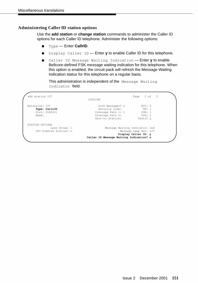
Issue 2 December 2001 151
Miscellaneous translations
Administering Caller ID station options
Use the add station or change station commands to administer the Caller ID options for each Caller ID telephone. Administer the following options:
■ Type — Enter CallrID.
■ Display Caller ID — Enter y to enable Caller ID for this telephone.
■ Caller ID Message Waiting Indication — Enter y to enable Bellcore-defined FSK message waiting indication for this telephone. When this option is enabled, the circuit pack will refresh the Message Waiting Indication status for this telephone on a regular basis.
This administration is independent of the Message Waiting Indicator field.
add station 107 Page 1 of 3 STATION
Extension: 107 Lock Messages? n BCC: 0 Type: CallrID Security Code: TN: 1 Port: 01A0201 Coverage Path 1: 1 COR: 1 Name: Coverage Path 2: COS: 1
Hunt-to Station: Tests? y
STATION OPTIONSLoss Group: 1 Message Waiting Indicator: led
Off Premise Station? n Message Lamp Ext: 107Display Caller ID: y
Caller ID Message Waiting Indication? n

152 Issue 2 December 2001
Translations and testing
Suite telephones (switch)
There are two features that better enable the setup of suite telephones: Suite Check-In and Station Hunt Before Coverage.
Suite Check-In allows the switch to check-in more than one telephone with one check-in command, whether the command is done from the switch or from the PMS. This is done by setting up a “hunt-to chain” between a primary telephone and up to 29 secondary telephones that are installed at different locations of a suite, or between telephones in separate rooms that have been linked as a suite of rooms. This feature does not apply to telephones that have bridged extensions of the primary extension; the secondary phones must have their own extension numbers.
For example, room 207 has three telephones, each with different extensions: 7207 (the primary extension), 7887, and 7897 (secondary extensions). You would administer station hunting from 7207 to 7887, and from 7887 to 7897. When you check in room 207 (extension 7207), the check-in process looks at the Hunt-To Station field, and if there is an extension in that field (in this case, 7887), that extension is also checked in. The system then checks the second extension’s Hunt-To Station field, and if there is an extension in that field (in this case, 7897), that extension is also checked in. You can link up to 30 stations as one suite of telephones. There is no limit to the number of suites you can create.
When two or more telephones are administered in this suite arrangement, you must also administer how incoming calls will be handled. There is a coverage option called Station Hunt Before Coverage. If Station Hunt Before Coverage is not enabled, calls to the primary extension (in this example, 7207) will go to coverage as specified in the coverage path criteria. If Station Hunt Before Coverage is enabled and there is a call to room 207 (extension 7207), if extension 7207 is busy, the call hunts to 7887. If extension 7887 is busy, the call hunts to extension 7897. If extension 7897 is busy, the call goes to coverage for extension 7207 (usually voice mail or the front desk). If any of the telephones in the station hunting group are idle, the call rings at that telephone and, when not answered, goes to coverage for extension 7207 (the primary extension). It is important to remember that hunting occurs only when an extension is busy, not when a call goes unanswered.

Issue 2 December 2001 153
Miscellaneous translations
Enabling Suite Check-In
Use the change system-parameters hospitality command, Page 3, to enable the Suite Check-In feature.
Administering station hunting
Use the add station XXXX or change station XXXX command to administer Hunt-To Stations. Based on the previous suite example, the following screen shows how you would administer station hunting from primary extension 7207 to secondary extension 7887.
change system-parameters hospitality Page 3 of 3ROOM STATES HOSPITALITY
Definition for Rooms in State 1: occupied/dirty Definition for Rooms in State 2: occupied/maid in room Definition for Rooms in State 3: occupied/clean Definition for Rooms in State 4: vacant/clean Definition for Rooms in State 5: Definition for Rooms in State 6:
HOSPITALITY FEATURESSuite Check-in? y
change station 7207 Page 1 of 3 STATION
Extension: 7207 Lock Messages? n BCC: 0 Type: CallrID Security Code: TN: 1 Port: 01A0201 Coverage Path 1: 1 COR: 1 Name: Coverage Path 2: COS: 1
Hunt-to Station: 7887 Tests? y
STATION OPTIONSLoss Group: 1 Message Waiting Indicator: led
Off Premise Station? n Message Lamp Ext: 7207Display Caller ID: y
Caller ID Message Waiting Indication? n

154 Issue 2 December 2001
Translations and testing
The following screen shows how you would then administer station hunting from secondary extension 7887 to secondary extension 7897.
You would repeat this administration for each telephone in the hunting group.
Administering Station Hunt Before Coverage
Use the change system-parameters coverage-forwarding command, Page 1, to enable or disable Station Hunt Before Coverage.
change station 7887 Page 1 of 3 STATION
Extension: 7887 Lock Messages? n BCC: 0 Type: CallrID Security Code: TN: 1 Port: 01A0201 Coverage Path 1: 1 COR: 1 Name: Coverage Path 2: COS: 1
Hunt-to Station: 7897 Tests? y
STATION OPTIONSLoss Group: 1 Message Waiting Indicator: led
Off Premise Station? n Message Lamp Ext: 7887Display Caller ID: y
Caller ID Message Waiting Indication? n
change system-parameters coverage-forwarding Page 1 of 2SYSTEM PARAMETERS - CALL COVERAGE/CALL FORWARDING
CALL COVERAGE/FORWARDING PARAMETERS
Local Cvg Subsequent Redirection/CFWD No Ans Interval (rings): 2Off-Net Cvg Subsequent Redirection/CFWD No Ans Interval (rings): 2
Coverage - Caller Response Interval (seconds): 4Threshold For Blocking Off-Net Redirection of Incoming Trunk Calls: 1
COVERAGEKeep Held SBA At Coverage Point? y
External Cvg Treatment For G3 Transferred Calls to G2 Supporting AUDIX? nImmediate Redirection on Receipt of PROGRESS Inband Information? n
Maintain SBA At Principal? y
Station Hunt Before Coverage? y
FORWARDINGCall Forward Override? n
Coverage after Forwarding? y
Issue 2 December 2001 155
Miscellaneous translations
Considerations
There are some considerations when setting up suite telephones.
■ Automatic Selection of DID Numbers and Custom Selection of VIP DID Numbers for Guest Rooms
If Automatic Selection of DID Numbers or Custom Selection of VIP DID Numbers is active, a DID number is assigned only to the primary extension (the one that appears in the check-in message), not to all of the secondary hunt-to extensions.
■ Automatic Wakeup
An Automatic Wakeup will be set and delivered only for the extension dialed, not the hunt-to extensions. If the wakeup call is placed and the telephone is busy, the wakeup call is retried two more times at 5-minute intervals.
■ Call Coverage
If Station Hunt Before Coverage is active, a call to a busy telephone tries to terminate to the hunt-to telephone before going to coverage. If the call goes to coverage, it goes to the coverage of the originally-dialed number. This is true unless the dialed number is an XDID number, and then the call goes to the coverage of the non-XDID telephone found in the XDID’s hunt-to field.
■ Call Detail Recording
Calls made from any of the secondary suite telephones will record the extension that placed the call, not the primary suite extension. Billing for calls from secondary extensions must be coordinated with the call accounting system vendor.
■ Check-In
If the primary extension or any of the secondary extensions are already in the checked-in state, the room will not be checked in, and the message “Room Already Occupied” will display.
■ Check-Out
If the primary extension is not in the occupied state, the message “Room Already Vacant” is displayed, and no rooms are checked out. If any secondary extensions are in the vacant state, all extensions will be checked out, and “Check Out Complete” is displayed.
156 Issue 2 December 2001
Translations and testing
■ Controlled Restrictions
When a controlled restriction is applied to the primary extension, the restriction is applied to all secondary extensions. This applies to restrictions done from the PMS, the attendant console, or from an authorized telephone.
■ Dial by Name
Secondary extensions that are checked in as part of a suite have an asterisk (*) inserted before the name that is stored in the names database. This prevents someone from using Dial by Name to access a secondary extension; only the primary extension can be accessed. However, when a guest calls the attendant or a display telephone from one of the secondary extensions, the guest name (with the asterisk in front of it) displays.
■ Do Not Disturb
When one of the telephones in a suite of telephones has Do Not Disturb activated, calls to that telephone go to intercept treatment, not to the next hunt-to telephone in the suite.
■ Housekeeping Status Updates
When room status is updated by housekeeping, it should be done from the primary extension for that room in order to be properly recorded. If housekeeping updates the status from the secondary extensions in the suite, the status for the suite (the primary extension) will not be updated.
■ Mailboxes
Mailboxes on the INTUITY system must be created manually for suites of rooms.
■ Message Waiting Lamps
Messages left for the primary extension do not light the message waiting lamps of the secondary extensions unless the Message Lamp Ext field for the secondary extensions contains the primary extension. In some cases, the customer will want each telephone to have its own message waiting lamp. In other cases, the customer will want a single message waiting lamp for all telephones in a suite.

Issue 2 December 2001 157
Miscellaneous translations
■ PMS Synchronization
In some cases, the PMS database and the switch database may get out-of-sync, and the telephones in a suite may not have the same status. If this happens, front desk personnel may have to check out the room (saving any messages for that room) and then retry the check-in.
During a database swap, if the PMS sends an extension that should be checked in but that is not currently checked in, all extensions in the hunt-to chain are updated along with the primary extension, regardless of their current state.
During a Room Change, the information for the old primary extension and secondary hunt-to extensions is cleared. All of the old information is inserted for the new room number.
During a Room Swap, the system will change the guest name and coverage path between the two rooms for the primary extension and the secondary extensions.
■ Send All Calls
When a telephone has Send All Calls active, and the telephone is called, the call goes directly to coverage, and no station hunting is done. If a hunt-to telephone has Send All Calls active, it is skipped in the hunt-to chain.
158 Issue 2 December 2001
Translations and testing
Mailboxes for guest rooms (INTUITY)
Guest room mailboxes are handled differently depending on which type of messaging link is used between the switch and the INTUITY.
When using TCP/IP or X.25 signaling, messages are sent between the PMS and the INTUITY system to automatically create guest room mailboxes when the PMS checks in a guest. No manual intervention is required.
When using Mode Code, you must manually create a mailbox for each guest room and leave the mailbox open at all times. This procedure is described in the INTUITY Lodging Release 4 Administration document or on the INTUITY Messaging Solutions Release 5 Documentation (CD). You must also use the Lodging Administration > System Parameter Administration command and set the Lamps ON For New Messages Only field to No. This means that the customer must clear messages manually every time a guest checks out. Instructions for this are also found in these documents.
When mailboxes are created, an * (asterisk) or 0 (zero) in the Guest Password field allows access to anyone checking that mailbox for messages. The system will not prompt the user for a password. If a # (pound or hash) is in the Guest Password field, guests can access their voice mailboxes only from their rooms until the guest assigns a valid password to the account. After assigning a password, guests can then get their messages from any location.
NOTE:The asterisk is the default password for a PMS-initiated check-in when the PMS does not send a password to the switch in stand-alone mode. The pound (or hash) symbol is the default password for a PMS-initiated check-in when the PMS does not send a password to the switch in the integrated switch link mode. See “Voice messaging-to-PMS translations and testing” on page 252 for more information.
If the guest mailbox has the Allow Personal Greeting field enabled, a guest can create a personal greeting, and also change his or her password when accessing his or her mailbox. A password must be four digits, non-sequential, non-repetitive, and not the same number as the room number.

Issue 2 December 2001 159
Miscellaneous translations
Recorded announcements (switch)
Use the change announcements command to assign extension numbers to be used for recorded announcements. There are two circuit packs that can be used to record announcements:
■ TN2501AP
The TN2501AP can record from 128 to 256 announcements. The maximum recording time per circuit pack is 1 hour. Each circuit pack has one dedicated port for recording announcements, one ethernet port for downloading wave (.wav) files, and 31 ports for playback. The TN2501AP is compatible with R9.5 and later.
NOTE:The TN2501AP circuit pack requires extensive administration which is described in the DEFINITY ECS Administrator’s Guide.
■ TN750
The TN750 supports up to 16 announcements. The maximum recording time per circuit pack is 256 seconds (TN750) or 512 seconds (TN750B or TN750C).
The extensions used for recorded announcements must already be administered in the dialing plan but cannot be used for any other purpose (such as stations or directory numbers).
change announcements Page 1 of 8ANNOUNCEMENTS/AUDIO SOURCES
Ann.No. Ext. Type COR TN Name Q QLen Pro Rate Port
1: 380 integrated 1 1 Wakeup n N/A n 32 01A142: 381 integrated 1 1 1st Auto Atnd n N/A n 32 01A143: 382 integrated 1 1 Dial Extension n N/A n 32 01A144: 383 integrated 1 1 Directory n N/A n 32 01A145: 1 1 n6: 1 1 n7: 1 1 n8: 1 1 n9: 1 1 n10: 1 1 n11: 1 1 n12: 1 1 n13: 1 1 n14: 1 1 n15: 1 1 n16: 1 1 n
160 Issue 2 December 2001
Translations and testing
Once you have designated which extensions will be used for recorded announcements, use the following procedures to record and test the announcements. You must record the announcements from the attendant console or from a station that has console permissions. It is recommended that you have a hotel employee record the announcements so the same person can be used for later changes or additions.
To record each of the announcements:
1. Go off-hook, and dial the Announcement FAC _____.
2. Dial the extension number of the announcement you want to record.
If an announcement session is already in progress, or if announcements are being saved or restored, you will hear reorder tone. Try again later.
3. Press , and record after the tone.
If the announcement already exists and is marked “protected” in the announcements screen, you will hear intercept tone.
4. Hang up when finished recording the message.
NOTE:The system records the sound of the receiver returning to the station. Press the switchhook with your finger, press , or hang up gently.
5. After waiting 15 seconds, dial the extension number of the announcement you just recorded.
6. Listen to the recording. If you need to record the message again, repeat this procedure. If the message is satisfactory, hang up, and repeat this procedure to record the other announcements.
To delete a recorded announcement:
1. Go off-hook at a station, and dial the Announcement FAC _____.
2. Dial the extension number of the announcement you want to delete.
3. Press .
Confirmation tone is heard, and the announcement is deleted.
4. Hang up.
5. Use the change announcements command to delete the announcement extension.
1
Drop
3
Issue 2 December 2001 161
Miscellaneous translations
If your system uses the TN750 or TN750B circuit packs, you must manually save the announcements recorded on those circuit packs. Use the save announcements command. If you do not save the announcements, all announcements recorded since the last save will be lost if the system loses power, or if the TN750 or TN750B circuit packs are removed from the system.
If your system uses only the TN750C or TN2501AP circuit packs, saving the announcements is not required. The TN750C and TN2501AP have on-board memory for all announcements.
Use the change system-parameters hospitality command to administer options associated with recorded announcements. On Page 2, administer the following:
■ Use the Announcement Type field to indicate the type of automatic wakeup announcement the hotel guest will receive. Allowable entries are as follows:
NOTE:One of the following four fields appears depending on what data is entered in the Announcement Type field.
Valid entries Usage
external Applicable when using an announcement adjunct.If external is used, complete the Auxiliary Board for Announcement field.
integrated Applicable when using the TN2501AP, TN750B, or TN750C announcement circuit packs.If integrated is used, complete the Integrated Announcement Extension field. The extension you enter must be a valid integrated announcement extension (administered on the Recorded Announce-ments screen) or a VDN. If you enter an invalid exten-sion, the switch displays an error message.
mult-integ Applicable when using the TN2501AP, TN750B, or TN750C announcement circuit packs.If mult-integ is used, complete the Default Announcement Extension field. The extension you enter must be a valid integrated announcement extension (administered on the Recorded Announce-ments screen) or a VDN. If you enter an invalid exten-sion, the switch displays an error message.
voice- synthesis If voice-synthesis is used, complete the Announce-ment Ports field.
music-on-hold If music-on-hold is used, no other field appears.
silence If silence is used, no other field appears.
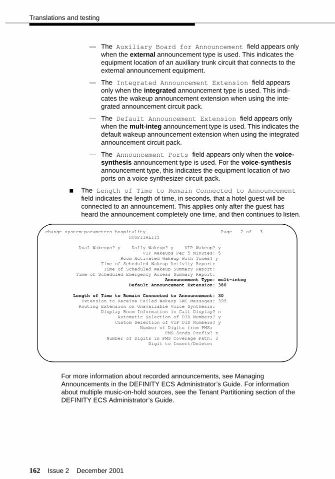
162 Issue 2 December 2001
Translations and testing
— The Auxiliary Board for Announcement field appears only when the external announcement type is used. This indicates the equipment location of an auxiliary trunk circuit that connects to the external announcement equipment.
— The Integrated Announcement Extension field appears only when the integrated announcement type is used. This indi-cates the wakeup announcement extension when using the inte-grated announcement circuit pack.
— The Default Announcement Extension field appears only when the mult-integ announcement type is used. This indicates the default wakeup announcement extension when using the integrated announcement circuit pack.
— The Announcement Ports field appears only when the voice-synthesis announcement type is used. For the voice-synthesis announcement type, this indicates the equipment location of two ports on a voice synthesizer circuit pack.
■ The Length of Time to Remain Connected to Announcement field indicates the length of time, in seconds, that a hotel guest will be connected to an announcement. This applies only after the guest has heard the announcement completely one time, and then continues to listen.
For more information about recorded announcements, see Managing Announcements in the DEFINITY ECS Administrator’s Guide. For information about multiple music-on-hold sources, see the Tenant Partitioning section of the DEFINITY ECS Administrator’s Guide.
change system-parameters hospitality Page 2 of 3 HOSPITALITY
Dual Wakeups? y Daily Wakeup? y VIP Wakeup? yVIP Wakeups Per 5 Minutes: 5
Room Activated Wakeup With Tones? y Time of Scheduled Wakeup Activity Report: Time of Scheduled Wakeup Summary Report: Time of Scheduled Emergency Access Summary Report: Announcement Type: mult-integ Default Announcement Extension: 380
Length of Time to Remain Connected to Announcement: 30 Extension to Receive Failed Wakeup LWC Messages: 399 Routing Extension on Unavailable Voice Synthesis: Display Room Information in Call Display? n
Automatic Selection of DID Numbers? yCustom Selection of VIP DID Numbers? y
Number of Digits from PMS:PMS Sends Prefix? n
Number of Digits in PMS Coverage Path: 3Digit to Insert/Delete:
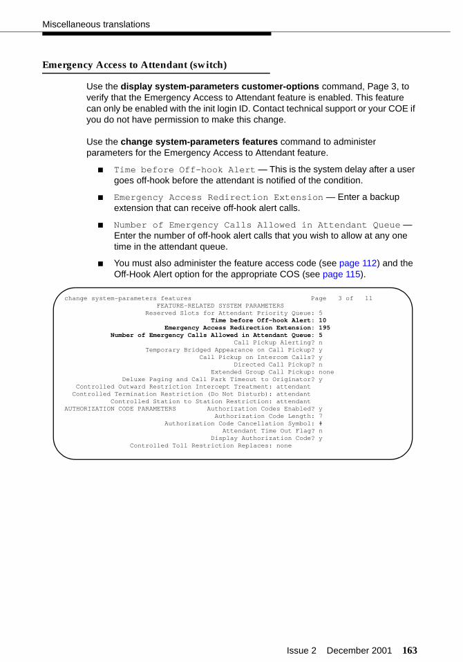
Issue 2 December 2001 163
Miscellaneous translations
Emergency Access to Attendant (switch)
Use the display system-parameters customer-options command, Page 3, to verify that the Emergency Access to Attendant feature is enabled. This feature can only be enabled with the init login ID. Contact technical support or your COE if you do not have permission to make this change.
Use the change system-parameters features command to administer parameters for the Emergency Access to Attendant feature.
■ Time before Off-hook Alert — This is the system delay after a user goes off-hook before the attendant is notified of the condition.
■ Emergency Access Redirection Extension — Enter a backup extension that can receive off-hook alert calls.
■ Number of Emergency Calls Allowed in Attendant Queue — Enter the number of off-hook alert calls that you wish to allow at any one time in the attendant queue.
■ You must also administer the feature access code (see page 112) and the Off-Hook Alert option for the appropriate COS (see page 115).
change system-parameters features Page 3 of 11 FEATURE-RELATED SYSTEM PARAMETERS Reserved Slots for Attendant Priority Queue: 5 Time before Off-hook Alert: 10 Emergency Access Redirection Extension: 195
Number of Emergency Calls Allowed in Attendant Queue: 5 Call Pickup Alerting? n
Temporary Bridged Appearance on Call Pickup? yCall Pickup on Intercom Calls? y
Directed Call Pickup? nExtended Group Call Pickup: none
Deluxe Paging and Call Park Timeout to Originator? y Controlled Outward Restriction Intercept Treatment: attendant Controlled Termination Restriction (Do Not Disturb): attendant Controlled Station to Station Restriction: attendantAUTHORIZATION CODE PARAMETERS Authorization Codes Enabled? y
Authorization Code Length: 7Authorization Code Cancellation Symbol: #
Attendant Time Out Flag? nDisplay Authorization Code? y
Controlled Toll Restriction Replaces: none
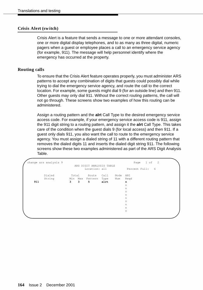
164 Issue 2 December 2001
Translations and testing
Crisis Alert (switch)
Crisis Alert is a feature that sends a message to one or more attendant consoles, one or more digital display telephones, and to as many as three digital, numeric pagers when a guest or employee places a call to an emergency service agency (for example, 911). The message will help personnel identify where the emergency has occurred at the property.
Routing calls
To ensure that the Crisis Alert feature operates properly, you must administer ARS patterns to accept any combination of digits that guests could possibly dial while trying to dial the emergency service agency, and route the call to the correct location. For example, some guests might dial 9 (for an outside line) and then 911. Other guests may only dial 911. Without the correct routing patterns, the call will not go through. These screens show two examples of how this routing can be administered.
Assign a routing pattern and the alrt Call Type to the desired emergency service access code. For example, if your emergency service access code is 911, assign the 911 digit string to a routing pattern, and assign it the alrt Call Type. This takes care of the condition when the guest dials 9 (for local access) and then 911. If a guest only dials 911, you also want the call to route to the emergency service agency. You must assign a dialed string of 11 with a different routing pattern that removes the dialed digits 11 and inserts the dialed digit string 911. The following screens show these two examples administered as part of the ARS Digit Analysis Table.
change ars analysis 9 Page 1 of 2ARS DIGIT ANALYSIS TABLE
Location: all Percent Full: 6
Dialed Total Route Call Node ANIString Min Max Pattern Type Num Reqd
911 3 3 5 alrt n n n n n n n n n n
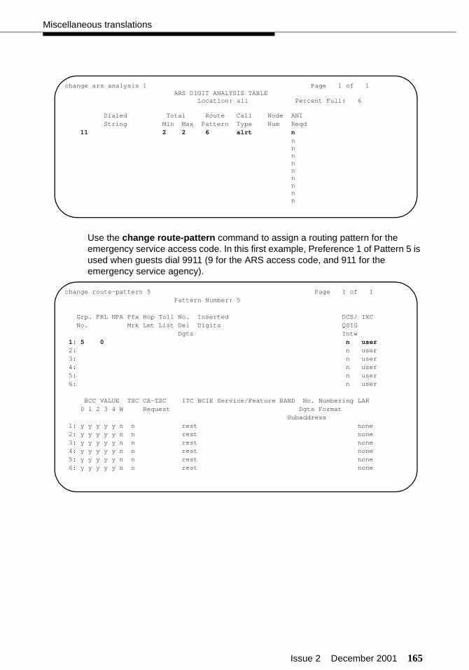
Issue 2 December 2001 165
Miscellaneous translations
Use the change route-pattern command to assign a routing pattern for the emergency service access code. In this first example, Preference 1 of Pattern 5 is used when guests dial 9911 (9 for the ARS access code, and 911 for the emergency service agency).
change ars analysis 1 Page 1 of 1ARS DIGIT ANALYSIS TABLE
Location: all Percent Full: 6
Dialed Total Route Call Node ANIString Min Max Pattern Type Num Reqd
11 2 2 6 alrt n n n n n n n n n n
change route-pattern 5 Page 1 of 1 Pattern Number: 5
Grp. FRL NPA Pfx Hop Toll No. Inserted DCS/ IXC No. Mrk Lmt List Del Digits QSIG Dgts Intw 1: 5 0 n user 2: n user 3: n user 4: n user 5: n user 6: n user
BCC VALUE TSC CA-TSC ITC BCIE Service/Feature BAND No. Numbering LAR 0 1 2 3 4 W Request Dgts Format Subaddress 1: y y y y y n n rest none 2: y y y y y n n rest none 3: y y y y y n n rest none 4: y y y y y n n rest none 5: y y y y y n n rest none 6: y y y y y n n rest none
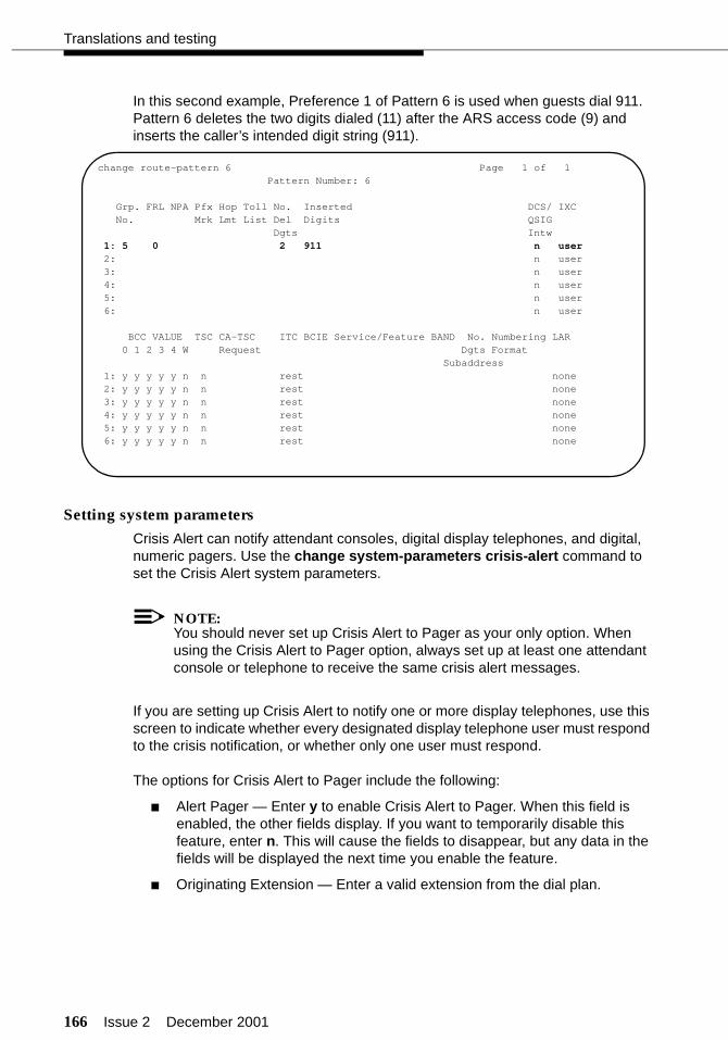
166 Issue 2 December 2001
Translations and testing
In this second example, Preference 1 of Pattern 6 is used when guests dial 911. Pattern 6 deletes the two digits dialed (11) after the ARS access code (9) and inserts the caller’s intended digit string (911).
Setting system parameters
Crisis Alert can notify attendant consoles, digital display telephones, and digital, numeric pagers. Use the change system-parameters crisis-alert command to set the Crisis Alert system parameters.
NOTE:You should never set up Crisis Alert to Pager as your only option. When using the Crisis Alert to Pager option, always set up at least one attendant console or telephone to receive the same crisis alert messages.
If you are setting up Crisis Alert to notify one or more display telephones, use this screen to indicate whether every designated display telephone user must respond to the crisis notification, or whether only one user must respond.
The options for Crisis Alert to Pager include the following:
■ Alert Pager — Enter y to enable Crisis Alert to Pager. When this field is enabled, the other fields display. If you want to temporarily disable this feature, enter n. This will cause the fields to disappear, but any data in the fields will be displayed the next time you enable the feature.
■ Originating Extension — Enter a valid extension from the dial plan.
change route-pattern 6 Page 1 of 1 Pattern Number: 6
Grp. FRL NPA Pfx Hop Toll No. Inserted DCS/ IXC No. Mrk Lmt List Del Digits QSIG Dgts Intw 1: 5 0 2 911 n user 2: n user 3: n user 4: n user 5: n user 6: n user
BCC VALUE TSC CA-TSC ITC BCIE Service/Feature BAND No. Numbering LAR 0 1 2 3 4 W Request Dgts Format Subaddress 1: y y y y y n n rest none 2: y y y y y n n rest none 3: y y y y y n n rest none 4: y y y y y n n rest none 5: y y y y y n n rest none 6: y y y y y n n rest none
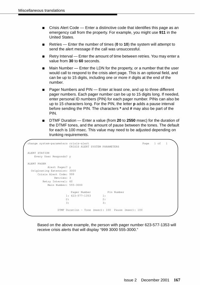
Issue 2 December 2001 167
Miscellaneous translations
■ Crisis Alert Code — Enter a distinctive code that identifies this page as an emergency call from the property. For example, you might use 911 in the United States.
■ Retries — Enter the number of times (0 to 10) the system will attempt to send the alert message if the call was unsuccessful.
■ Retry Interval — Enter the amount of time between retries. You may enter a value from 30 to 60 seconds.
■ Main Number — Enter the LDN for the property, or a number that the user would call to respond to the crisis alert page. This is an optional field, and can be up to 15 digits, including one or more # digits at the end of the number.
■ Pager Numbers and PIN — Enter at least one, and up to three different pager numbers. Each pager number can be up to 15 digits long. If needed, enter personal ID numbers (PIN) for each pager number. PINs can also be up to 15 characters long. For the PIN, the letter p adds a pause interval before sending the PIN. The characters * and # may also be part of the PIN.
■ DTMF Duration — Enter a value (from 20 to 2550 msec) for the duration of the DTMF tones, and the amount of pause between the tones. The default for each is 100 msec. This value may need to be adjusted depending on trunking requirements.
Based on the above example, the person with pager number 623-577-1353 will receive crisis alerts that will display “999 3000 555-3000.”
change system-parameters crisis-alert Page 1 of 1CRISIS ALERT SYSTEM PARAMETERS
ALERT STATIONEvery User Responds? y
ALERT PAGERAlert Pager? y
Originating Extension: 3000Crisis Alert Code: 999
Retries: 3Retry Interval: 60
Main Number: 555-3000
Pager Number Pin Number1: 623-577-1353 1:2: 2:3: 3:
DTMF Duration - Tone (msec): 100 Pause (msec): 100

168 Issue 2 December 2001
Translations and testing
Trunk groups (switch)
Use the add trunk-group command to assign each trunk group. For more information on administering trunk groups, including CAMA 911 emergency trunks, see the DEFINITY ECS Administrator’s Guide.
■ COR — Each trunk group must have a COR.
■ CDR Reports — Enter y for every trunk group that the customer wishes to record. Usually, only outgoing trunk groups are recorded.
■ Dial Access — Enter n.
NOTE:When a call accounting package is first installed, the set of extensions and trunks administered on the switch is coordinated with the call accounting vendor. If extensions and trunks are added at a later date, the call accounting vendor must be notified so changes can be added to the call accounting package.
add trunk-group 1 Page 1 of 11 TRUNK GROUP
Group Number: 1 Group Type: co CDR Reports: y Group Name: Outside Call COR: 20 TN: 1 TAC: 710 Direction: two-way Outgoing Display? n Dial Access? n Busy Threshold: 10 Night Service:Queue Length: 0 Country: 1 Incoming Destination: attd Comm Type: voice Auth Code? n Digit Absorption List: Prefix-1? y Trunk Flash? n Toll Restricted? y
TRUNK PARAMETERS Trunk Type: ground-start Outgoing Dial Type: tone Cut-Through? n Trunk Termination: rc Disconnect Timing(msec): 500
Auto Guard? n Call Still Held? n Sig Bit Inversion: noneAnalog Loss Group: 6 Digital Loss Group: 11
Trunk Gain: high
Disconnect Supervision - In? y Out? n Answer Supervision Timeout: 10 Receive Answer Supervision? n
Issue 2 December 2001 169
Miscellaneous translations
Assigning DID numbers to guest rooms (switch)
Front desk personnel can assign a DID number to a guest room when the guest checks in, or at any time during the guest’s stay. A DID number gives the guest a direct phone number to his or her room that can be shared with family or business associates. A DID number also enhances guest security by allowing people to contact guests without giving out the guest room number. The DID number can be dialed as an extension from within the property, or as a 7- or 10-digit number by callers outside of the property. These numbers are selected from a block of DID numbers purchased by the customer from the customer’s local telephone company.
DID numbers can be assigned to guest rooms using two different features:
■ Automatic Selection of DID Numbers, or
■ Custom Selection of VIP DID numbers.
Automatic Selection of DID Numbers allows the switch to automatically assign a DID number to a guest room when the guest checks in. The switch selects the DID numbers from an administered set of DID numbers that have been designated for automatic assignment. The numbers are selected on a rotating basis, with the oldest DID number assigned with each new check-in. After the switch assigns a DID number, the number can be viewed and changed manually from an attendant console or backup telephone. The pool of DID numbers used for this feature is separate from the pool of numbers used for the Custom Selection of VIP DID Numbers feature.
Custom Selection of VIP DID Numbers allows the switch to assign a special DID number to a guest room when a guest checks in. The front desk personnel select the DID numbers from an administered set of DID numbers that have been designated for custom, or repeat, assignment. This feature is used for VIP guests that wish to have the same DID number every time they check in to the property. After a DID number is assigned, the number can be viewed and changed manually from an attendant console or backup telephone. The pool of DID numbers used for this feature is separate from the pool of numbers used for the Automatic Selection of DID Numbers feature.
These features work when checking in either from the attendant console or backup telephone, or when checking in using a PMS, as long as the PMS software has been updated to use this feature. The switch PMS messages have been changed to allow the PMS to request a DID number, which the switch sends as part of the check-in response (automatic selection) or as a separate message (custom selection). See the GuestWorks and DEFINITY ECS Property Management System Interface Specifications (555-231-601, Issue 3 or later) for more details.
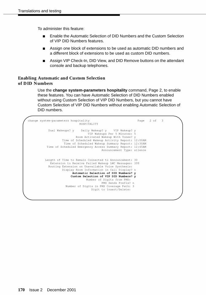
170 Issue 2 December 2001
Translations and testing
To administer this feature:
■ Enable the Automatic Selection of DID Numbers and the Custom Selection of VIP DID Numbers features.
■ Assign one block of extensions to be used as automatic DID numbers and a different block of extensions to be used as custom DID numbers.
■ Assign VIP Check-In, DID View, and DID Remove buttons on the attendant console and backup telephones.
Enabling Automatic and Custom Selectionof DID Numbers
Use the change system-parameters hospitality command, Page 2, to enable these features. You can have Automatic Selection of DID Numbers enabled without using Custom Selection of VIP DID Numbers, but you cannot have Custom Selection of VIP DID Numbers without enabling Automatic Selection of DID numbers.
change system-parameters hospitality Page 2 of 3 HOSPITALITY
Dual Wakeups? y Daily Wakeup? y VIP Wakeup? yVIP Wakeups Per 5 Minutes: 5
Room Activated Wakeup With Tones? y Time of Scheduled Wakeup Activity Report: 12:00AM Time of Scheduled Wakeup Summary Report: 12:30AM Time of Scheduled Emergency Access Summary Report: 12:45AM Announcement Type: silence
Length of Time to Remain Connected to Announcement: 30 Extension to Receive Failed Wakeup LWC Messages: 399 Routing Extension on Unavailable Voice Synthesis: Display Room Information in Call Display? n
Automatic Selection of DID Numbers? yCustom Selection of VIP DID Numbers? y
Number of Digits from PMS:PMS Sends Prefix? n
Number of Digits in PMS Coverage Path: 3Digit to Insert/Delete:

Issue 2 December 2001 171
Miscellaneous translations
Assigning the DID numbers
Use the add station XXXX command to assign the DID numbers. Use a block of unassigned extensions from the switch numbering plan. The DID numbers must match the DID numbers assigned by the customer’s telephone company. To maintain consistency, the extension length on the switch must match the extension length of the DID numbers assigned by the telephone company.
The quantity and management of DID numbers assigned is up to the customer. The customer may want to limit the quantity of DID numbers assigned, or have the ability to give out a DID number to every guest. If the customer wants to use both automatic and custom selection of DID numbers, they must have one set of automatic DID numbers and another set of custom DID numbers. When assigning the DID numbers, do not use a COS that has the Client Room feature enabled. This prevents someone from accidentally checking in or checking out a DID telephone number.
The following examples show and XDID and XDIDVIP station assignment.
When you first assign the DID numbers, the Hunt-to Station field does not have an assignment (it is a display-only field). When a DID number is assigned to a guest room extension when the guest checks in, that guest room extension is then displayed in the Hunt-to Station field of the assigned DID number. Use the list station type xdid or list station type xdidvip commands to list the DID number assignments.
After you assign one DID number, use the duplicate station XXXX command to create the rest of your DID numbers. Duplication can be used for only one station type at a time (XDID or XIDVIP, but not both at the same time).
add station 6000 Page 1 of 1 STATION
Extension: 6000 BCC: 0 Type: xdid TN: 1
Coverage Path 1: 5 COR: 1 Name: Coverage Path 2: COS: 10
Hunt-to Station:
add station 6224 Page 1 of 1 STATION
Extension: 6224 BCC: 0 Type: xdidvip TN: 1
Coverage Path 1: 5 COR: 1 Name: Coverage Path 2: COS: 10
Hunt-to Station:
172 Issue 2 December 2001
Translations and testing
Assigning DID number feature buttons
Assign the following feature buttons to use the DID number features:
■ did-view
■ did-remove
■ vip-chkin
These buttons can be assigned to attendant consoles and backup telephones with console permissions. See “Attendant console button layouts (switch)” on page 132 and “Backup telephone button layouts (switch)” on page 142 for more information.
Considerations
■ Call Coverage
Calls using a DID number will cover to the guest’s coverage path as if the guest’s extension was dialed.
■ Call Coverage for Unassigned DID Numbers
Assign a special Call Coverage path for all DID numbers. This coverage should terminate to the attendant or to a recording stating that the number dialed is no longer in use. When the DID number is assigned to a guest room, the coverage follows the path for that guest. When the DID number is not being used, the call will go to the attendant or to a recording.
If the coverage goes to a special mailbox on the voice mail system, you can administer the system so the caller can dial 0 to get the front desk. For example, the recording could say “Thank you for calling the ABC Hotel. The guest you have called is no longer available at this number. Please press 0 for assistance.”
■ Call Detail Recording
Incoming calls are recorded for the DID number, not the room extension number. Billing for incoming calls to DID numbers must be coordinated with the call accounting system vendor.
■ Call Vectoring
You cannot route a vector step to an xdid or xdidvip station type.

Issue 2 December 2001 173
Miscellaneous translations
■ Collect Calls
In general, collect calls to DID guest room numbers should not be allowed. Check with your local telephone company to see if the incoming trunks can be administered to deny collect calls to the guest rooms.
■ Number Rotation for Automatic Selection of DID Numbers
Initially, the DID numbers are assigned during check-in in the order in which they were administered on the switch. Over time, that order will become more random, depending on the length of each guest’s stay.
This rotation of numbers is not used for Custom Selection of VIP DID Numbers since those numbers are manually assigned.
■ Save Translations
The DID number assignments are saved in translations (either when done manually or during the automatic save every night). Any system resets of level 3 or higher will lose DID number check-in assignments since the last save.

174 Issue 2 December 2001
Translations and testing
Automatic Wakeup options (switch)
Automatic Wakeup is a standard feature when hospitality is enabled on the Customer Options form. In addition to the standard single wakeup option set up by front desk personnel, the following options are available for the Automatic Wakeup feature:
■ Dual Wakeup
Dual wakeup calls can be set up by front desk personnel, or by the guest when using the Wakeup Activation via Tones feature.
■ Daily Wakeup
Daily wakeup calls can only be set up by front desk personnel.
■ VIP Wakeup, including the maximum number of VIP Wakeup requests allowed during a 5-minute interval
VIP wakeup calls can only be set up by front desk personnel.
■ Wakeup Activation via Tones
This feature allows a guest to set up wakeup calls without having to use the Speech Synthesizer circuit pack.
NOTE:If Wakeup Activation via Tones is enabled, the wakeup feature provided by a Speech Synthesizer circuit pack is disabled from service.
■ If a wakeup call is not acknowledged by the guest answering the call, the switch keeps track of these failed wakeups. Use the Extension to Receive Failed Wakeup LWC Messages field to assign a message waiting lamp to notify front desk personnel when this happens. See more about this in “Attendant console button layouts (switch)” on page 132 and “Backup telephone button layouts (switch)” on page 142.
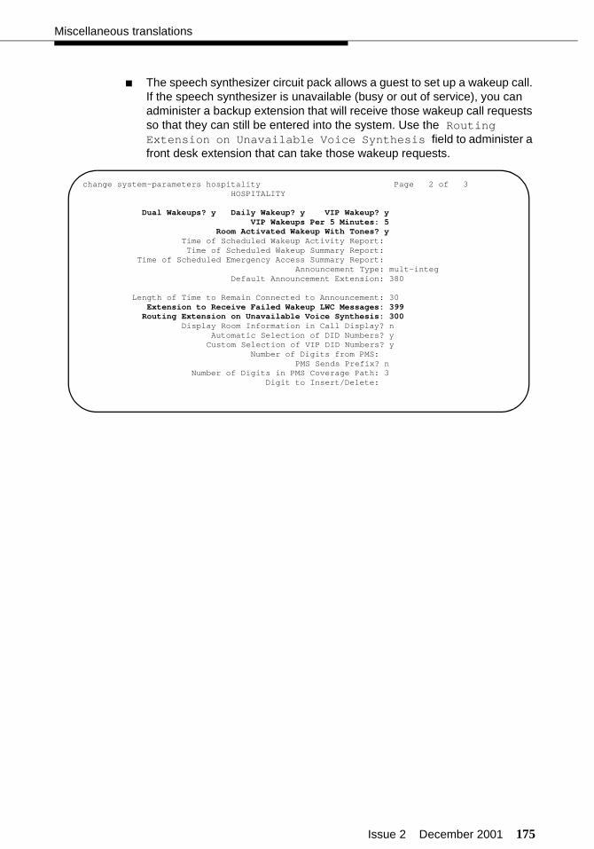
Issue 2 December 2001 175
Miscellaneous translations
■ The speech synthesizer circuit pack allows a guest to set up a wakeup call. If the speech synthesizer is unavailable (busy or out of service), you can administer a backup extension that will receive those wakeup call requests so that they can still be entered into the system. Use the Routing Extension on Unavailable Voice Synthesis field to administer a front desk extension that can take those wakeup requests.
change system-parameters hospitality Page 2 of 3 HOSPITALITY
Dual Wakeups? y Daily Wakeup? y VIP Wakeup? yVIP Wakeups Per 5 Minutes: 5
Room Activated Wakeup With Tones? y Time of Scheduled Wakeup Activity Report: Time of Scheduled Wakeup Summary Report: Time of Scheduled Emergency Access Summary Report:
Announcement Type: mult-integ Default Announcement Extension: 380
Length of Time to Remain Connected to Announcement: 30 Extension to Receive Failed Wakeup LWC Messages: 399 Routing Extension on Unavailable Voice Synthesis: 300 Display Room Information in Call Display? n
Automatic Selection of DID Numbers? yCustom Selection of VIP DID Numbers? y
Number of Digits from PMS:PMS Sends Prefix? n
Number of Digits in PMS Coverage Path: 3Digit to Insert/Delete:
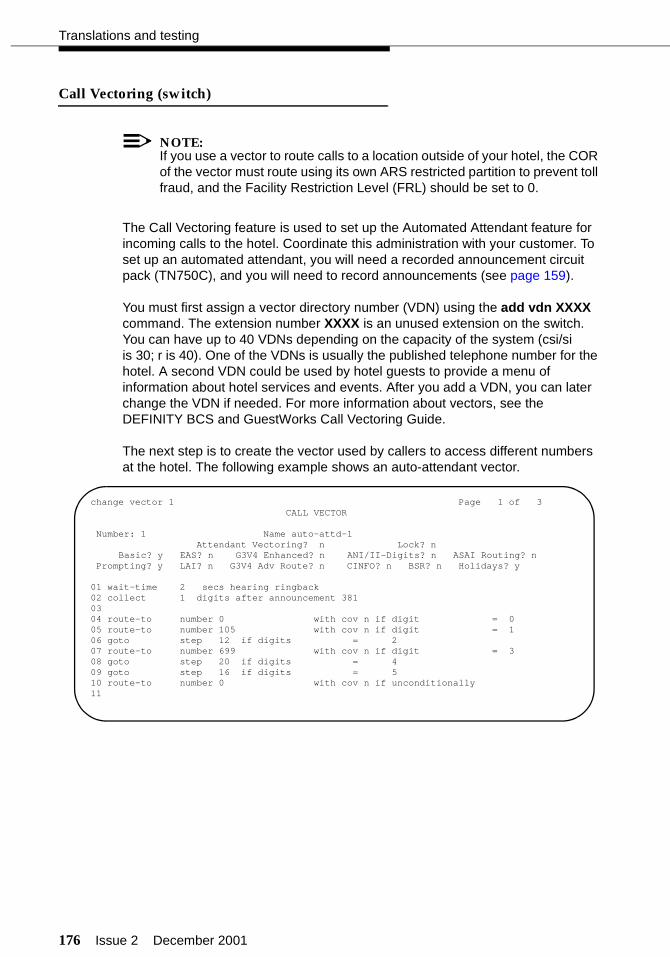
176 Issue 2 December 2001
Translations and testing
Call Vectoring (switch)
NOTE:If you use a vector to route calls to a location outside of your hotel, the COR of the vector must route using its own ARS restricted partition to prevent toll fraud, and the Facility Restriction Level (FRL) should be set to 0.
The Call Vectoring feature is used to set up the Automated Attendant feature for incoming calls to the hotel. Coordinate this administration with your customer. To set up an automated attendant, you will need a recorded announcement circuit pack (TN750C), and you will need to record announcements (see page 159).
You must first assign a vector directory number (VDN) using the add vdn XXXX command. The extension number XXXX is an unused extension on the switch. You can have up to 40 VDNs depending on the capacity of the system (csi/si is 30; r is 40). One of the VDNs is usually the published telephone number for the hotel. A second VDN could be used by hotel guests to provide a menu of information about hotel services and events. After you add a VDN, you can later change the VDN if needed. For more information about vectors, see the DEFINITY BCS and GuestWorks Call Vectoring Guide.
The next step is to create the vector used by callers to access different numbers at the hotel. The following example shows an auto-attendant vector.
change vector 1 Page 1 of 3CALL VECTOR
Number: 1 Name auto-attd-1Attendant Vectoring? n Lock? n
Basic? y EAS? n G3V4 Enhanced? n ANI/II-Digits? n ASAI Routing? nPrompting? y LAI? n G3V4 Adv Route? n CINFO? n BSR? n Holidays? y
01 wait-time 2 secs hearing ringback02 collect 1 digits after announcement 38103 04 route-to number 0 with cov n if digit = 005 route-to number 105 with cov n if digit = 106 goto step 12 if digits = 207 route-to number 699 with cov n if digit = 308 goto step 20 if digits = 409 goto step 16 if digits = 510 route-to number 0 with cov n if unconditionally11
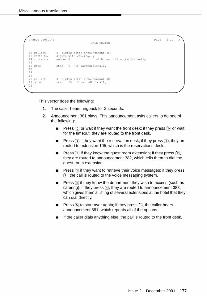
Issue 2 December 2001 177
Miscellaneous translations
This vector does the following:
1. The caller hears ringback for 2 seconds.
2. Announcement 381 plays. This announcement asks callers to do one of the following:
■ Press or wait if they want the front desk; if they press or wait for the timeout, they are routed to the front desk.
■ Press if they want the reservation desk; if they press , they are routed to extension 105, which is the reservations desk.
■ Press if they know the guest room extension; if they press , they are routed to announcement 382, which tells them to dial the guest room extension.
■ Press if they want to retrieve their voice messages; if they press , the call is routed to the voice messaging system.
■ Press if they know the department they wish to access (such as catering); if they press , they are routed to announcement 383, which gives them a listing of several extensions at the hotel that they can dial directly.
■ Press to start over again; if they press , the caller hears announcement 381, which repeats all of the options.
■ If the caller dials anything else, the call is routed to the front desk.
change vector 1 Page 2 of 3CALL VECTOR
12 collect 3 digits after announcement 38213 route-to digits with coverage y14 route-to number 0 with cov n if unconditionally15 16 goto step 2 if unconditionally17181920 collect 3 digits after announcement 38321 goto step 13 if unconditionally22
0 0
1 1
2 2
3
3
4
4
5 5
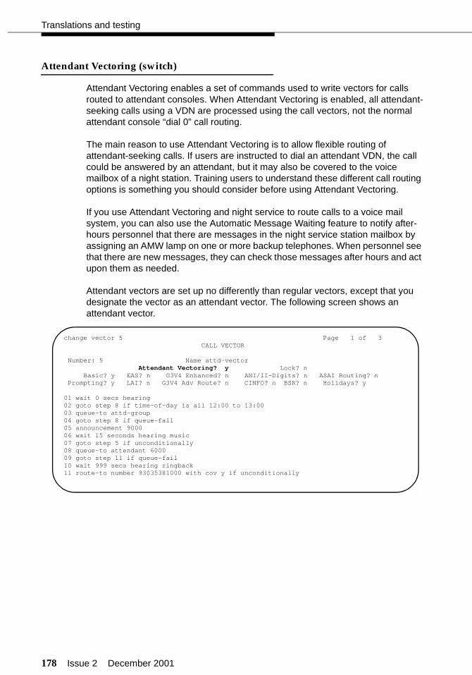
178 Issue 2 December 2001
Translations and testing
Attendant Vectoring (switch)
Attendant Vectoring enables a set of commands used to write vectors for calls routed to attendant consoles. When Attendant Vectoring is enabled, all attendant-seeking calls using a VDN are processed using the call vectors, not the normal attendant console “dial 0” call routing.
The main reason to use Attendant Vectoring is to allow flexible routing of attendant-seeking calls. If users are instructed to dial an attendant VDN, the call could be answered by an attendant, but it may also be covered to the voice mailbox of a night station. Training users to understand these different call routing options is something you should consider before using Attendant Vectoring.
If you use Attendant Vectoring and night service to route calls to a voice mail system, you can also use the Automatic Message Waiting feature to notify after-hours personnel that there are messages in the night service station mailbox by assigning an AMW lamp on one or more backup telephones. When personnel see that there are new messages, they can check those messages after hours and act upon them as needed.
Attendant vectors are set up no differently than regular vectors, except that you designate the vector as an attendant vector. The following screen shows an attendant vector.
change vector 5 Page 1 of 3CALL VECTOR
Number: 5 Name attd-vectorAttendant Vectoring? y Lock? n
Basic? y EAS? n G3V4 Enhanced? n ANI/II-Digits? n ASAI Routing? nPrompting? y LAI? n G3V4 Adv Route? n CINFO? n BSR? n Holidays? y
01 wait 0 secs hearing02 goto step 8 if time-of-day is all 12:00 to 13:0003 queue-to attd-group04 goto step 8 if queue-fail05 announcement 900006 wait 15 seconds hearing music07 goto step 5 if unconditionally08 queue-to attendant 600009 goto step 11 if queue-fail10 wait 999 secs hearing ringback11 route-to number 93035381000 with cov y if unconditionally
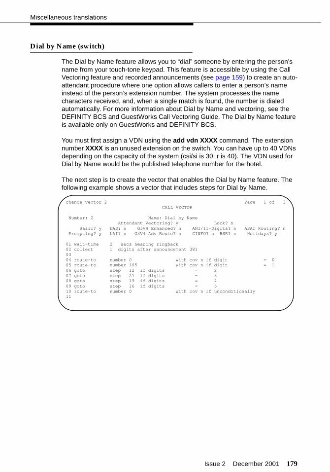
Issue 2 December 2001 179
Miscellaneous translations
Dial by Name (switch)
The Dial by Name feature allows you to “dial” someone by entering the person’s name from your touch-tone keypad. This feature is accessible by using the Call Vectoring feature and recorded announcements (see page 159) to create an auto-attendant procedure where one option allows callers to enter a person’s name instead of the person’s extension number. The system processes the name characters received, and, when a single match is found, the number is dialed automatically. For more information about Dial by Name and vectoring, see the DEFINITY BCS and GuestWorks Call Vectoring Guide. The Dial by Name feature is available only on GuestWorks and DEFINITY BCS.
You must first assign a VDN using the add vdn XXXX command. The extension number XXXX is an unused extension on the switch. You can have up to 40 VDNs depending on the capacity of the system (csi/si is 30; r is 40). The VDN used for Dial by Name would be the published telephone number for the hotel.
The next step is to create the vector that enables the Dial by Name feature. The following example shows a vector that includes steps for Dial by Name.
change vector 2 Page 1 of 3CALL VECTOR
Number: 2 Name: Dial by NameAttendant Vectoring? y Lock? n
Basic? y EAS? n G3V4 Enhanced? n ANI/II-Digits? n ASAI Routing? nPrompting? y LAI? n G3V4 Adv Route? n CINFO? n BSR? n Holidays? y
01 wait-time 2 secs hearing ringback02 collect 1 digits after announcement 38103 04 route-to number 0 with cov n if digit = 005 route-to number 105 with cov n if digit = 106 goto step 12 if digits = 207 goto step 21 if digits = 308 goto step 19 if digits = 409 goto step 16 if digits = 510 route-to number 0 with cov n if unconditionally11
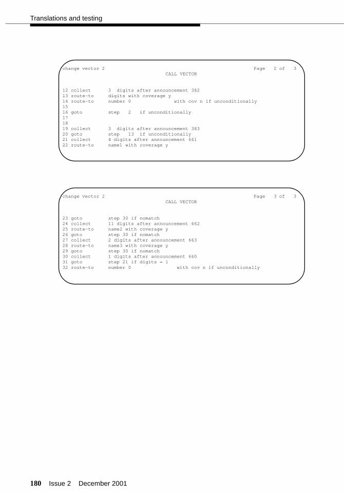
180 Issue 2 December 2001
Translations and testing
change vector 2 Page 2 of 3CALL VECTOR
12 collect 3 digits after announcement 38213 route-to digits with coverage y14 route-to number 0 with cov n if unconditionally15 16 goto step 2 if unconditionally171819 collect 3 digits after announcement 38320 goto step 13 if unconditionally21 collect 4 digits after announcement 66122 route-to name1 with coverage y
change vector 2 Page 3 of 3CALL VECTOR
23 goto step 30 if nomatch24 collect 11 digits after announcement 66225 route-to name2 with coverage y26 goto step 30 if nomatch27 collect 2 digits after announcement 66328 route-to name3 with coverage y29 goto step 30 if nomatch30 collect 1 digits after announcement 66031 goto step 21 if digits = 132 route-to number 0 with cov n if unconditionally

Issue 2 December 2001 181
Miscellaneous translations
This Dial by Name vector does the following:
1. The caller hears ringback for 2 seconds.
2. Announcement 381 plays. This announcement instructs the caller to do one of the following:
■ Press or wait if the caller wants the operator; if the caller presses or waits for the timeout, the caller is routed to the operator.
■ Press if the caller wants the front desk; if the caller presses , the caller is routed to extension 105, which is the front desk.
■ Press if the caller knows the person’s extension; if the caller presses , the caller is routed to announcement 382, which tells the caller to dial the person’s extension.
■ Press if the caller knows the person’s name; if the caller presses , the following sub-procedure occurs:
a. Announcement 661 plays requesting that the caller enter the first four letters of the person’s last name.
If there is a single match, the call is redirected.
If there are multiple matches, continue with Step b.
If there is no match, go to Step d.
b. Announcement 662 plays requesting that the caller enter the rest of the person’s last name, followed by the key.
If there is a single match, the call is redirected.
If there are multiple matches, continue with Step c.
If there is no match, go to Step d.
c. Announcement 663 plays requesting that the caller enter the first two letters of the person’s first name.
If there is a single match, the call is redirected.
If there is no match, continue with Step d.
d. Since there are no matches, announcement 660 plays telling the caller that they can press to try again, or press to get an operator.
■ Press if the caller knows the department (such as housekeeping) the caller wishes to access. If the caller presses , the caller is routed to announcement 383, which gives the caller a listing of several departments that the caller can dial directly.
■ Press to start over again; if the caller presses , the caller hears announcement 381, which repeats all of the options.
■ If the caller dials anything else, the call is routed to the operator.
0
0
1 1
2
2
3
3
#
1 0
4
4
5 5

182 Issue 2 December 2001
Translations and testing
Trunk-to-Trunk Transfer (switch)
Use the change system-parameters features command to enable Trunk-to-Trunk Transfer only if it is requested by the customer. This feature is normally disabled because of the possibility of toll fraud.
! CAUTION:If Trunk-to-Trunk Transfer is enabled, calls made to guest rooms can be transferred outside of the hotel, and toll charges may be lost for some calls.
change system-parameters features Page 1 of 10 FEATURE-RELATED SYSTEM PARAMETERS
Self Station Display Enabled? y Trunk-to-Trunk Transfer: noneAutomatic Callback - No Answer Timeout Interval (rings): 3 Call Park Timeout Interval (minutes): 10 Off-Premises Tone Detect Timeout Interval (seconds): 20
AAR/ARS Dial Tone Required? y Music/Tone on Hold: music Port: 01B1101 Music (or Silence) on Transferred Trunk Calls? no DID/Tie/ISDN Intercept Treatment: attd Messaging Service Adjunct (MSA) Connected? n Internal Automatic Answer for Attendant Extended Calls? n Automatic Circuit Assurance (ACA) Enabled? y
ACA Referral Calls: localACA Referral Destination: attd
ACA Short Holding Time Originating Extension: 3070ACA Long Holding Time Originating Extension: 3070
Abbreviated Dial Programming by Assigned Lists? n Auto Abbreviated/Delayed Transition Interval (rings): 2
Protocol for Caller ID Analog Terminals: BellcoreDisplay Calling Number for Room to Room Caller ID Calls? n
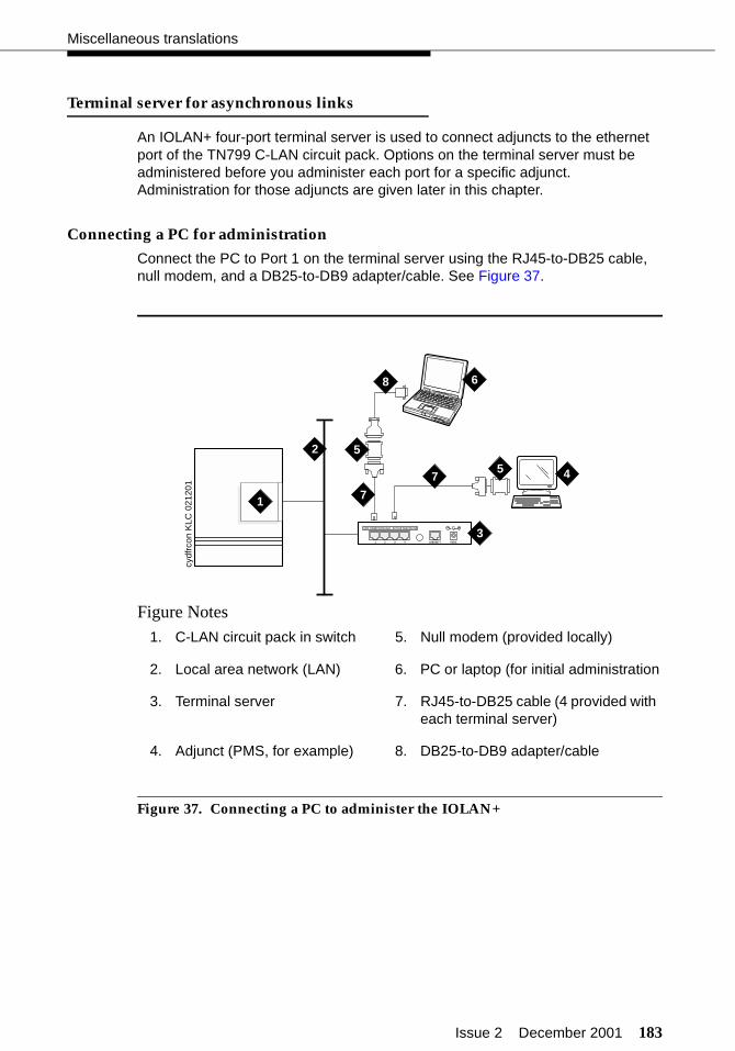
Issue 2 December 2001 183
Miscellaneous translations
Terminal server for asynchronous links
An IOLAN+ four-port terminal server is used to connect adjuncts to the ethernet port of the TN799 C-LAN circuit pack. Options on the terminal server must be administered before you administer each port for a specific adjunct. Administration for those adjuncts are given later in this chapter.
Connecting a PC for administration
Connect the PC to Port 1 on the terminal server using the RJ45-to-DB25 cable, null modem, and a DB25-to-DB9 adapter/cable. See Figure 37.
Figure Notes
Figure 37. Connecting a PC to administer the IOLAN+
1. C-LAN circuit pack in switch 5. Null modem (provided locally)
2. Local area network (LAN) 6. PC or laptop (for initial administration
3. Terminal server 7. RJ45-to-DB25 cable (4 provided with each terminal server)
4. Adjunct (PMS, for example) 8. DB25-to-DB9 adapter/cable
cydf
rcon
KLC
021
201
1
2
4
DATA CONNECTIONS ONLY - NOT FOR TELECOM USE
1 2 3 4 10BASE-T 5VDC
3
7
7
8
5
5
6
184 Issue 2 December 2001
Translations and testing
Administering the terminal server
Before beginning the initial administration, make sure you have the following information:
■ IP address and subnet mask for terminal server
■ Host name for terminal server
■ IP address of C-LAN Ethernet interface
■ Port number of C-LAN Ethernet interface where adjunct connects.
Setting up HyperTerminal on the computer
Use the HyperTerminal software program that comes with Windows to administer the terminal server.
To set up HyperTerminal:
1. Open HyperTerminal.
2. Click on File > Properties > Connect tab. In the Connect using: field, select COM n, where n is the communication port your computer is using.
3. Click on CONFIGURE and set the bits per second field to 9600 and the Flow control field to Hardware.
4. Click OK, OK.
5. Press ENTER to get the login prompt.
Navigating the terminal server
Refer to the terminal server user and administration guide for details. In general,
■ Use the arrow keys to move to a menu item.
■ Use the TAB key to move from field to field horizontally.
■ Use the ENTER key to choose an item.
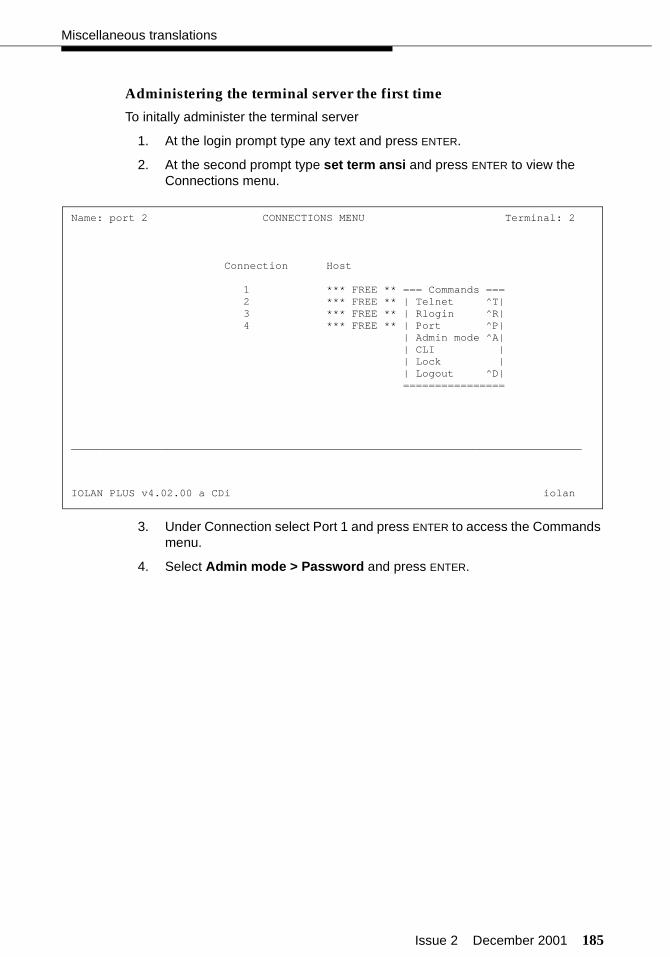
Issue 2 December 2001 185
Miscellaneous translations
Administering the terminal server the first time
To initally administer the terminal server
1. At the login prompt type any text and press ENTER.
2. At the second prompt type set term ansi and press ENTER to view the Connections menu.
3. Under Connection select Port 1 and press ENTER to access the Commands menu.
4. Select Admin mode > Password and press ENTER.
Name: port 2 CONNECTIONS MENU Terminal: 2
Connection Host
1 *** FREE ** === Commands === 2 *** FREE ** | Telnet ^T| 3 *** FREE ** | Rlogin ^R| 4 *** FREE ** | Port ^P| | Admin mode ^A| | CLI | | Lock | | Logout ^D| ================
________________________________________________________________________________
IOLAN PLUS v4.02.00 a CDi iolan

186 Issue 2 December 2001
Translations and testing
.
5. Type iolan, the default password, and press ENTER.
The Administration Menu changes, offering more options.
6. Select server and press ENTER to view the Server Configuration menu.
Name: port 2 ADMINISTRATION MENU Terminal: 2
gateway Examine/modify gateway table. host Examine/modify host table. line Terminal configuration organised by line. password Specify password to allow modification of menu items. port Terminal configuration organised by port. quit Return to connections menu. server Examine/modify Server parameters. stats Examine Server statistics.
Password [ ]
________________________________________________________________________________
IOLAN PLUS v4.02.00 a CDi iolan-st
** Administrator ** SERVER CONFIGURATION Terminal: 2
Name [iolan ] Debug mode [0 ] IP address [168.92.1.99 ] Subnet mask [222.222.0.0 ] Ethernet address [00:80:d4:03:11:cd] Ethernet interface [AUTO ] Language [English ] Identification [ ] Lock [Disabled] Password limit [5 ] CR to initiate [No ] SNAP encoding [Disabled] Boot host [ ] Boot diagnostics [Enabled ] Boot file [ ] Init file [ ] MOTD file [ ] Domain name [ ] Name server [ ] NS Port [53 ] WINS server [ ]________________________________________________________________________________
Name used for prompts and message on bottom right of screen.
IOLAN PLUS v4.02.00 a CDi iolan
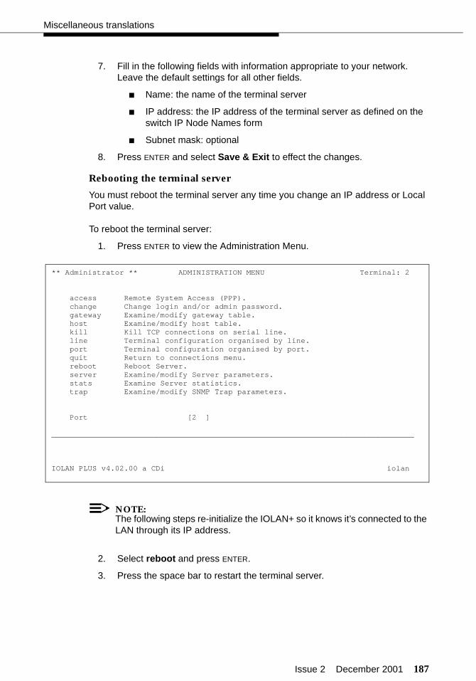
Issue 2 December 2001 187
Miscellaneous translations
7. Fill in the following fields with information appropriate to your network. Leave the default settings for all other fields.
■ Name: the name of the terminal server
■ IP address: the IP address of the terminal server as defined on the switch IP Node Names form
■ Subnet mask: optional
8. Press ENTER and select Save & Exit to effect the changes.
Rebooting the terminal server
You must reboot the terminal server any time you change an IP address or Local Port value.
To reboot the terminal server:
1. Press ENTER to view the Administration Menu. .
NOTE:The following steps re-initialize the IOLAN+ so it knows it’s connected to the LAN through its IP address.
2. Select reboot and press ENTER.
3. Press the space bar to restart the terminal server.
** Administrator ** ADMINISTRATION MENU Terminal: 2
access Remote System Access (PPP). change Change login and/or admin password. gateway Examine/modify gateway table. host Examine/modify host table. kill Kill TCP connections on serial line. line Terminal configuration organised by line. port Terminal configuration organised by port. quit Return to connections menu. reboot Reboot Server. server Examine/modify Server parameters. stats Examine Server statistics. trap Examine/modify SNMP Trap parameters.
Port [2 ]
________________________________________________________________________________
IOLAN PLUS v4.02.00 a CDi iolan
188 Issue 2 December 2001
Translations and testing
Administering the gateway
NOTE:If the C-LAN circuit pack and terminal server are in the same subnet, skip this procedure.
To administer the gateway:
1. Select Admin mode > Password and press ENTER.
2. Type iolan and press ENTER.
3. Select gateway to access the Gateway menu
4. Fill in the following fields for Entry 1:
■ Destination: C-LAN IP address on the switch IP Node Names form
■ Gateway: Gateway address
■ Netmask: Subnet mask
NOTE:The following steps reinitialize the terminal server so it knows it is connected to the LAN through your gateway.
5. Select reboot and press ENTER.
6. Press the space bar to restart the terminal server.
Issue 2 December 2001 189
Switch-to-PMS link translations and testing
Switch-to-PMS link translations and testing
Administration of the switch-to-PMS link includes the following:
■ Hospitality parameters (page 189)
■ Link connectivity, which is administered one of two ways:
— TCP/IP link using the C-LAN circuit pack (page 193)
— DCP link using the network control (netcon) data module for si sys-tem (page 197) and a processor data module on all systems (page 198)
■ Housekeeping status feature access codes and definitions (page 198)
■ Controlled restrictions (page 200).
Hospitality parameters
Use the change system-parameters hospitality command to administer the hospitality parameters for the PMS. These assignments must be coordinated with the PMS vendor and the customer. On Page 1, administer the following:
■ For the Message Waiting Configuration field, enter act-nopms if the INTUITY is controlling the message waiting lamps, and enter act-pms if the PMS is controlling the message waiting lamps. If the PMS supports text messaging, enter act-pms. If all messaging is handled on the INTUITY system, enter act-nopms.
■ The Controlled Restrictions Configuration, Housekeeper Information Configuration, and Client Room Coverage Path Configuration fields control features offered by some PMS vendors. If the PMS vendor supports the feature, enter act-pms in the corresponding field. If the PMS vendor does not support the feature, enter act-nopms in the corresponding field. Note that if the Client Room Coverage Path Configuration field is administered incorrectly, administered coverage paths for rooms will be deleted.
■ In the PMS Endpoint field, enter PMS for a TCP/IP link using a terminal server, or enter the extension number of the PMS data module for a DCP link.
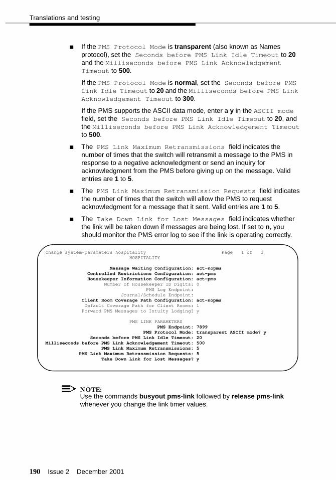
190 Issue 2 December 2001
Translations and testing
■ If the PMS Protocol Mode is transparent (also known as Names protocol), set the Seconds before PMS Link Idle Timeout to 20 and the Milliseconds before PMS Link Acknowledgement Timeout to 500.
If the PMS Protocol Mode is normal, set the Seconds before PMS Link Idle Timeout to 20 and the Milliseconds before PMS Link Acknowledgement Timeout to 300.
If the PMS supports the ASCII data mode, enter a y in the ASCII mode field, set the Seconds before PMS Link Idle Timeout to 20, and the Milliseconds before PMS Link Acknowledgement Timeout to 500.
■ The PMS Link Maximum Retransmissions field indicates the number of times that the switch will retransmit a message to the PMS in response to a negative acknowledgment or send an inquiry for acknowledgment from the PMS before giving up on the message. Valid entries are 1 to 5.
■ The PMS Link Maximum Retransmission Requests field indicates the number of times that the switch will allow the PMS to request acknowledgment for a message that it sent. Valid entries are 1 to 5.
■ The Take Down Link for Lost Messages field indicates whether the link will be taken down if messages are being lost. If set to n, you should monitor the PMS error log to see if the link is operating correctly.
NOTE:Use the commands busyout pms-link followed by release pms-link whenever you change the link timer values.
change system-parameters hospitality Page 1 of 3 HOSPITALITY
Message Waiting Configuration: act-nopms Controlled Restrictions Configuration: act-pms Housekeeper Information Configuration: act-pms Number of Housekeeper ID Digits: 0 PMS Log Endpoint:
Journal/Schedule Endpoint: Client Room Coverage Path Configuration: act-nopms Default Coverage Path for Client Rooms: 1
Forward PMS Messages to Intuity Lodging? y
PMS LINK PARAMETERSPMS Endpoint: 7899
PMS Protocol Mode: transparent ASCII mode? ySeconds before PMS Link Idle Timeout: 20
Milliseconds before PMS Link Acknowledgement Timeout: 500 PMS Link Maximum Retransmissions: 5 PMS Link Maximum Retransmission Requests: 5 Take Down Link for Lost Messages? y
Issue 2 December 2001 191
Switch-to-PMS link translations and testing
On Page 2, administer the following:
■ The Number of Digits From PMS field should be left blank, and the Digit to Insert/Delete field may need to be administered. If the room numbers use a combination of 3- and 4-digit or 4- and 5-digit extension numbers, you must enter the leading digit that must be inserted when sent from the PMS to the switch and that must be deleted when sent from the switch to the PMS.
NOTE:The PMS interface supports 3-, 4-, or 5-digit extensions, but be aware that prefixed extensions do not send the entire number across the interface. Only the assigned extension number is sent. Therefore, you should not use prefixed extensions for numbers that are also going to use the Insert/Delete Digit function.
This works as shown in the following example:
— Digit Insertion — If the digits received by the switch are 123, and the insertion digit is 7, extension 7123 is checked to see if it is a valid extension. If 7123 is valid, the message is processed for extension 7123; if extension 7123 is not valid, the switch assumes that the message is for extension 123 and processes it accordingly. If both 7123 and 123 are valid, the message will only be processed for extension 7123. Numbering conflicts such as this should be avoided when possible.
— Digit Deletion — The switch checks the extension number before the number is sent to the PMS. If the extension number contains the maximum number of digits translated for a leading digit, and the leading digit matches the administered Insert/Delete digit, the digit is deleted before sending the extension to the PMS.
For example, if the Insert/Delete digit is 7, and extensions 712 and 7123 are valid on the switch, 712 will be sent as 712; however, 7123 is sent as 123. This example presumes that there are no 5-digit extensions starting with 7 on the switch.
■ The PMS Sends Prefix field indicates whether the PMS sends a prefix digit to the switch as part of the room numbering plan.
NOTE:If the PMS Sends Prefix field is set to n, and the Number of Digits from PMS field is blank, the switch will not support an extension that starts with 0.

192 Issue 2 December 2001
Translations and testing
■ The Number of Digits in PMS Coverage Path field indicates whether the coverage paths are 3 or 4 digits long.
change system-parameters hospitality Page 2 of 3 HOSPITALITY
Dual Wakeups? y Daily Wakeup? y VIP Wakeup? yVIP Wakeups Per 5 Minutes: 5
Room Activated Wakeup With Tones? y Time of Scheduled Wakeup Activity Report: Time of Scheduled Wakeup Summary Report: Time of Scheduled Emergency Access Summary Report: Announcement Type: mult-integ Default Announcement Extension: 380
Length of Time to Remain Connected to Announcement: 30 Extension to Receive Failed Wakeup LWC Messages: 399 Routing Extension on Unavailable Voice Synthesis: Display Room Information in Call Display? n
Automatic Selection of DID Numbers? yCustom Selection of VIP DID Numbers? y
Number of Digits from PMS:PMS Sends Prefix? n
Number of Digits in PMS Coverage Path: 3Digit to Insert/Delete:
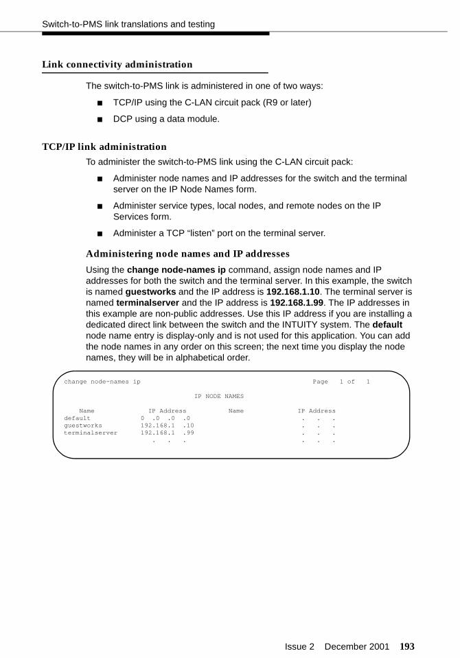
Issue 2 December 2001 193
Switch-to-PMS link translations and testing
Link connectivity administration
The switch-to-PMS link is administered in one of two ways:
■ TCP/IP using the C-LAN circuit pack (R9 or later)
■ DCP using a data module.
TCP/IP link administration
To administer the switch-to-PMS link using the C-LAN circuit pack:
■ Administer node names and IP addresses for the switch and the terminal server on the IP Node Names form.
■ Administer service types, local nodes, and remote nodes on the IP Services form.
■ Administer a TCP “listen” port on the terminal server.
Administering node names and IP addresses
Using the change node-names ip command, assign node names and IP addresses for both the switch and the terminal server. In this example, the switch is named guestworks and the IP address is 192.168.1.10. The terminal server is named terminalserver and the IP address is 192.168.1.99. The IP addresses in this example are non-public addresses. Use this IP address if you are installing a dedicated direct link between the switch and the INTUITY system. The default node name entry is display-only and is not used for this application. You can add the node names in any order on this screen; the next time you display the node names, they will be in alphabetical order.
change node-names ip Page 1 of 1
IP NODE NAMES
Name IP Address Name IP Addressdefault 0 .0 .0 .0 . . .guestworks 192.168.1 .10 . . .terminalserver 192.168.1 .99 . . .
. . . . . .
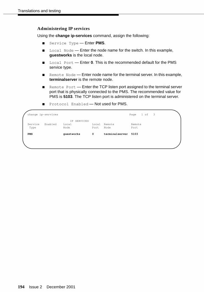
194 Issue 2 December 2001
Translations and testing
Administering IP services
Using the change ip-services command, assign the following:
■ Service Type — Enter PMS.
■ Local Node — Enter the node name for the switch. In this example, guestworks is the local node.
■ Local Port — Enter 0. This is the recommended default for the PMS service type.
■ Remote Node — Enter node name for the terminal server. In this example, terminalserver is the remote node.
■ Remote Port — Enter the TCP listen port assigned to the terminal server port that is physically connected to the PMS. The recommended value for PMS is 5103. The TCP listen port is administered on the terminal server.
■ Protocol Enabled — Not used for PMS.
change ip-services Page 1 of 3
IP SERVICESService Enabled Local Local Remote RemoteType Node Port Node Port
PMS guestworks 0 terminalserver 5103

Issue 2 December 2001 195
Switch-to-PMS link translations and testing
Administering a port on the terminal server
The initial options on the terminal server must be administered before you administer a port (see “Terminal server for asynchronous links” on page 183). Use this procedure when connecting the PMS to the terminal server (see Figure 37 on page 183).
To administer a port on the terminal server:
1. Select Admin mode > Password and press ENTER.
2. Type iolan and press ENTER.
3. Select port and press ENTER.
4. Type port number, where port number is the port that the adjunct connects to, and press ENTER to view the Port Setup Menu.
** Administrator ** PORT SETUP MENU Terminal: 2 Hardware Flow ctrl Keys Speed [9600 ] Flow ctrl [None ] Hot [^]] Intr [^C] Parity [None] Input Flow [Enabled ] Quit [^@] Kill [^U] Bit [8] Output Flow [Enabled ] Del [^@] Sess [^@] Stop [1 ] Echo [^@] Break [Disabled] IP Addresses Monitor DSR [Yes ] Src [ ] Mask [ ] Monitor DCD [No ] Dst [ ]
User Options Access Name [pms ] Keepalive [No ] Access [Remote ] Terminal type [undef ] Rlogin/Telnet [Telnet] Authentication [None ] TERM [ ] Debug options [No ] Mode [Raw ] Video pages [0] Map CR to CR LF [No ] Connection [None ] CLI/Menu [Menu] Hex data [No ] Host [ ] Reset Term [No ] Secure [No ] Remote Port [0 ] MOTD [No ] Local Port [5103 ]
________________________________________________________________________________
196 Issue 2 December 2001
Translations and testing
5. Fill in the following fields. Leave the default settings for all other fields.
■ Speed: must match the PMS port speed (default is 9600)
■ Monitor DSR: Yes
■ Name: pms
■ Flow ctrl: None
■ Access: Remote
■ Mode: Raw
■ Remote Port: 0 (C-LAN Ethernet port where IP adjunct service is offered)
■ Local Port: 5103 (must match the value of Remote Port on the DEFINTY IP Services screen)
6. Press ENTER and select Save & Exit to effect the changes.
7. Press ENTER again to view the Administration Menu.
8. Select kill to disable the port connection.
9. When administration is complete, from the Connections Menu, select logout (or press Ctrl D).
10. Close HyperTerminal.
11. Continue with “Housekeeping status” on page 198.
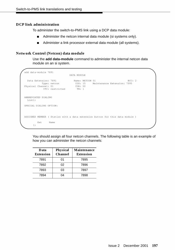
Issue 2 December 2001 197
Switch-to-PMS link translations and testing
DCP link administration
To administer the switch-to-PMS link using a DCP data module:
■ Administer the netcon internal data module (si systems only).
■ Administer a link processor external data module (all systems).
Network Control (Netcon) data module
Use the add data-module command to administer the internal netcon data module on an si system.
You should assign all four netcon channels. The following table is an example of how you can administer the netcon channels:
Data Extension
Physical Channel
Maintenance Extension
7891 01 7895
7892 02 7896
7893 03 7897
7894 04 7898
add data-module 7891 DATA MODULE
Data Extension: 7891 Name: NETCON 01 BCC: 2 Type: netcon COS: 15 Maintenance Extension: 7995Physical Channel: 01 COR: 50
ITC: restricted TN: 1
ABBREVIATED DIALING List1:
SPECIAL DIALING OPTION:
ASSIGNED MEMBER ( Station with a data extension button for this data module )
Ext Name 1:

198 Issue 2 December 2001
Translations and testing
Link data modules
Use the add data-module command to administer the external data module connected between the switch and the PMS.
Housekeeping status
Use the change feature-access-codes command to assign the housekeeping status feature access codes. Administer only the feature access codes that the vendor supports and that match the status definitions.
add data-module 7899 DATA MODULE
Data Extension: 7899 Name: PMS LINK BCC: 2 Type: pdm COS: 1 Remote Loop-Around Test? n Port: 01B0102 COR: 50 Secondary data module? n
ITC: restricted TN: 1 Connected to: dte
ABBREVIATED DIALING List1:
SPECIAL DIALING OPTION:
ASSIGNED MEMBER ( Station with a data extension button for this data module )
Ext Name 1:
change feature-access-codes Page 5 of 5 FEATURE ACCESS CODE (FAC) Hospitality Features
Automatic Wakeup Call Access Code: *98 Housekeeping Status (Client Room) Access Code: *81 Housekeeping Status (Client Room) Access Code: *82 Housekeeping Status (Client Room) Access Code: *83 Housekeeping Status (Client Room) Access Code: *84 Housekeeping Status (Client Room) Access Code: Housekeeping Status (Client Room) Access Code: Housekeeping Status (Station) Access Code: Housekeeping Status (Station) Access Code: Housekeeping Status (Station) Access Code: Housekeeping Status (Station) Access Code: Verify Wakeup Announcement Access Code: *89 Voice Do Not Disturb Access Code: *33
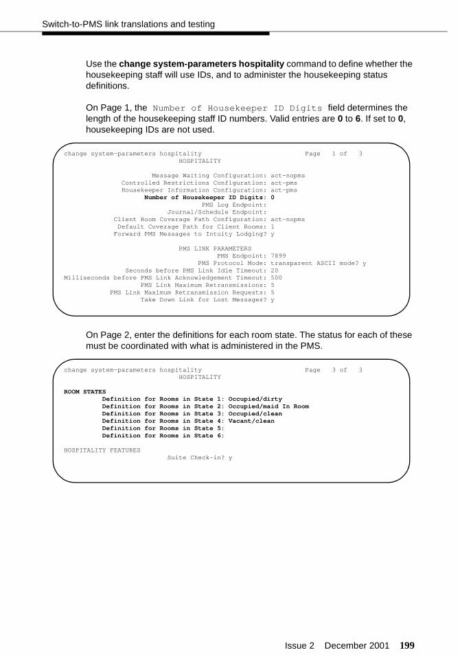
Issue 2 December 2001 199
Switch-to-PMS link translations and testing
Use the change system-parameters hospitality command to define whether the housekeeping staff will use IDs, and to administer the housekeeping status definitions.
On Page 1, the Number of Housekeeper ID Digits field determines the length of the housekeeping staff ID numbers. Valid entries are 0 to 6. If set to 0, housekeeping IDs are not used.
On Page 2, enter the definitions for each room state. The status for each of these must be coordinated with what is administered in the PMS.
change system-parameters hospitality Page 1 of 3 HOSPITALITY
Message Waiting Configuration: act-nopms Controlled Restrictions Configuration: act-pms Housekeeper Information Configuration: act-pms Number of Housekeeper ID Digits: 0 PMS Log Endpoint: Journal/Schedule Endpoint: Client Room Coverage Path Configuration: act-nopms Default Coverage Path for Client Rooms: 1
Forward PMS Messages to Intuity Lodging? y
PMS LINK PARAMETERS PMS Endpoint: 7899 PMS Protocol Mode: transparent ASCII mode? y
Seconds before PMS Link Idle Timeout: 20Milliseconds before PMS Link Acknowledgement Timeout: 500 PMS Link Maximum Retransmissions: 5 PMS Link Maximum Retransmission Requests: 5 Take Down Link for Lost Messages? y
change system-parameters hospitality Page 3 of 3 HOSPITALITY
ROOM STATES Definition for Rooms in State 1: Occupied/dirty Definition for Rooms in State 2: Occupied/maid In Room Definition for Rooms in State 3: Occupied/clean Definition for Rooms in State 4: Vacant/clean Definition for Rooms in State 5: Definition for Rooms in State 6:
HOSPITALITY FEATURESSuite Check-in? y

200 Issue 2 December 2001
Translations and testing
Controlled Restrictions
When Controlled Restrictions are applied to guest rooms, calls made to those rooms or from those rooms are routed to intercept treatment. The recommended intercept treatment is shown in the following example. Use the change system-parameters features command to set the controlled restriction intercept treatment.
The PMS automatically applies controlled restrictions to guest rooms as guests check in and check out. If the PMS link is down, you will have to apply and remove controlled restrictions manually. Administer the controlled restriction feature access codes using the screens beginning on page 112. You can also assign feature buttons on the attendant console for the Controlled Restrictions feature. See “Attendant console button layouts (switch)” on page 132 for more information.
Optionally, customers can substitute Toll Restriction for the standard Outward or Station-to-Station restrictions. Using the Controlled Toll Restriction replaces field, you can enter none, outward, or station-station. If you enter none, the customer has access to Outward, Total, Termination, and Station-to-Station restrictions. If you enter outward, the customer has access to Toll, Total, Termination, and Station-to-Station restrictions. If you enter station-station, the customer has access to Outward, Total, Termination, and Toll restrictions. In this example, Toll Restriction is substituted for Station-Station Restriction.
Instruct customers to use the GuestWorks and DEFINITY ECS Hospitality Operations document to learn more about Controlled Restrictions and how to use them.
change system-parameters features Page 3 of 10 FEATURE-RELATED SYSTEM PARAMETERS
Reserved Slots for Attendant Priority Queue: 5 Time before Off-hook Alert: 10 Emergency Access Redirection Extension:
Number of Emergency Calls Allowed in Attendant Queue: 5 Call Pickup Alerting? n
Temporary Bridged Appearance on Call Pickup? yCall Pickup on Intercom Calls? y
Directed Call Pickup? nExtended Group Call Pickup: none
Deluxe Paging and Call Park Timeout to Originator? y Controlled Outward Restriction Intercept Treatment: attendant Controlled Termination Restriction (Do Not Disturb): coverage Controlled Station to Station Restriction: attendantAUTHORIZATION CODE PARAMETERS Authorization Codes Enabled? y
Authorization Code Length: 7Authorization Code Cancellation Symbol: #
Attendant Time Out Flag? nDisplay Authorization Code? y
Controlled Toll Restriction Replaces: station-station
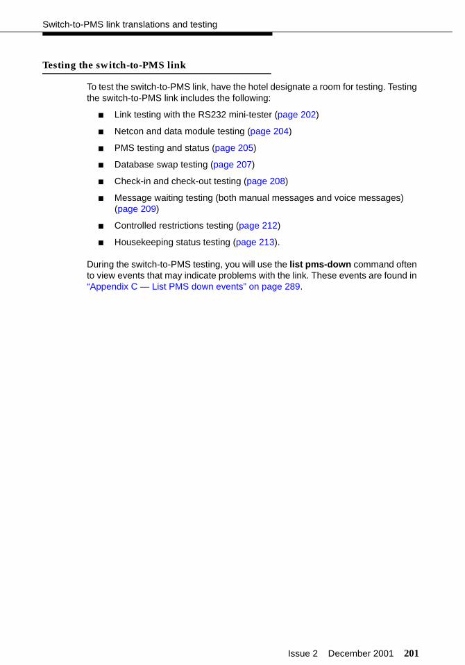
Issue 2 December 2001 201
Switch-to-PMS link translations and testing
Testing the switch-to-PMS link
To test the switch-to-PMS link, have the hotel designate a room for testing. Testing the switch-to-PMS link includes the following:
■ Link testing with the RS232 mini-tester (page 202)
■ Netcon and data module testing (page 204)
■ PMS testing and status (page 205)
■ Database swap testing (page 207)
■ Check-in and check-out testing (page 208)
■ Message waiting testing (both manual messages and voice messages) (page 209)
■ Controlled restrictions testing (page 212)
■ Housekeeping status testing (page 213).
During the switch-to-PMS testing, you will use the list pms-down command often to view events that may indicate problems with the link. These events are found in “Appendix C — List PMS down events” on page 289.

202 Issue 2 December 2001
Translations and testing
Switch-to-PMS link testing with theRS232 Mini-Tester
Using the RS232 Mini-Tester (see the Note on page 5), check the status of the PMS link. The leads marked with an asterisk are controlled by the switch, and the PMS controls the other leads. If any switch leads are dark, there is no connection.
! CAUTION:After using a mini-tester to check data leads, you MUST remove the mini-tester from the connection. DO NOT leave the mini-tester in-line during actual operation.
If the link to a PMS is active, the mini-tester should show the following. The Physical Link State should be up, and the Protocol State should be up. If this is the status of the link, proceed to “Netcon and link data module testing” on page 204. Otherwise, look at the other results in this section.
If the link is idle, the mini-tester may show the following. The Physical Link State will be down, and the Protocol State will be down. Possible causes may be that the switch or PMS are not administered correctly, or the PMS software is not running.
NOTE:The CTS lead shows green when used with an 8400B. RTS will be lit on the front panel of the 7400A and 7400B.
TD
RTS
DTR
RD*
CTS*DSR*
CD*
green
green
red
green
red
green
green
TD
RTS
DTR
RD*
CTS*DSR*
CD*
red
red
red
redred
redred

Issue 2 December 2001 203
Switch-to-PMS link translations and testing
If the link to a PMS is idle, the mini-tester may also show the following. The Physical Link State will be down, and the Protocol State will be down. Possible causes may be that the PMS hardware is powered-up, but the switch is not administered correctly, or the PMS link is busied out at the switch.
NOTE:The CTS lead shows green when used with an 8400B. RTS will be lit on the front panel of the 7400A or 7400B.
TD
RTS
DTR
RD*
CTS*DSR*
CD*
red
red
redred
red
green
green
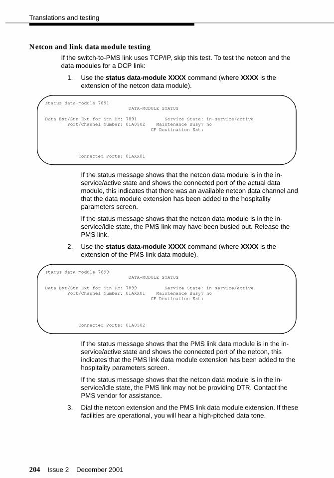
204 Issue 2 December 2001
Translations and testing
Netcon and link data module testing
If the switch-to-PMS link uses TCP/IP, skip this test. To test the netcon and the data modules for a DCP link:
1. Use the status data-module XXXX command (where XXXX is the extension of the netcon data module).
If the status message shows that the netcon data module is in the in-service/active state and shows the connected port of the actual data module, this indicates that there was an available netcon data channel and that the data module extension has been added to the hospitality parameters screen.
If the status message shows that the netcon data module is in the in-service/idle state, the PMS link may have been busied out. Release the PMS link.
2. Use the status data-module XXXX command (where XXXX is the extension of the PMS link data module).
If the status message shows that the PMS link data module is in the in-service/active state and shows the connected port of the netcon, this indicates that the PMS link data module extension has been added to the hospitality parameters screen.
If the status message shows that the netcon data module is in the in-service/idle state, the PMS link may not be providing DTR. Contact the PMS vendor for assistance.
3. Dial the netcon extension and the PMS link data module extension. If these facilities are operational, you will hear a high-pitched data tone.
status data-module 7891DATA-MODULE STATUS
Data Ext/Stn Ext for Stn DM: 7891 Service State: in-service/activePort/Channel Number: 01A0502 Maintenance Busy? no
CF Destination Ext:
Connected Ports: 01AXX01
status data-module 7899DATA-MODULE STATUS
Data Ext/Stn Ext for Stn DM: 7899 Service State: in-service/activePort/Channel Number: 01AXX01 Maintenance Busy? no
CF Destination Ext:
Connected Ports: 01A0502
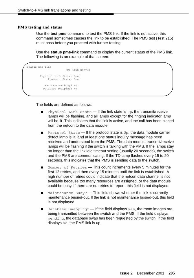
Issue 2 December 2001 205
Switch-to-PMS link translations and testing
PMS testing and status
Use the test pms command to test the PMS link. If the link is not active, this command sometimes causes the link to be established. The PMS test (Test 215) must pass before you proceed with further testing.
Use the status pms-link command to display the current status of the PMS link. The following is an example of that screen:
The fields are defined as follows:
■ Physical Link State — If the link state is Up, the transmit/receive lamps will be flashing, and all lamps except for the ringing indicator lamp will be lit. This indicates that the link is active, and the call has been placed from the netcon to the data module.
■ Protocol State — If the protocol state is Up, the data module carrier detect lamp is lit, and at least one status inquiry message has been received and understood from the PMS. The data module transmit/receive lamps will be flashing if the switch is talking with the PMS. If the lamps stay on longer than the link idle timeout setting (usually 20 seconds), the switch and the PMS are communicating. If the TD lamp flashes every 15 to 20 seconds, this indicates that the PMS is sending data to the switch.
■ Number of Retries — This count increments every 5 minutes for the first 12 retries, and then every 15 minutes until the link is established. A high number of retries could indicate that the netcon data channel is not available because too many resources are assigned, or the data module could be busy. If there are no retries to report, this field is not displayed.
■ Maintenance Busy? — This field shows whether the link is currently maintenance busied-out. If the link is not maintenance busied-out, this field is not displayed.
■ Database Swapping? — If the field displays yes, the room images are being transmitted between the switch and the PMS. If the field displays pending, the database swap has been requested by the switch. If the field displays no, the PMS link is up.
status pms-linkPMS LINK STATUS
Physical Link State: DownProtocol State: Down
Maintenance Busy? NoDatabase Swapping? No
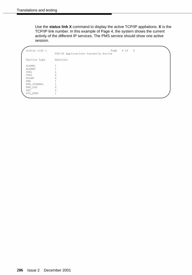
206 Issue 2 December 2001
Translations and testing
Use the status link X command to display the active TCP/IP appliations. X is the TCP/IP link number. In this example of Page 4, the system shows the current activity of the different IP services. The PMS service should show one active session.
status link 1 Page 4 of 4TCP/IP Applications Currently Active
Service Type Sessions
ALARM1 1ALARM2 1CDR1 1CDR2 0DOLAN 0PMS 1PMS_JOURNAL 1PMS_LOG 0SAT 3SYS_PRNT 1
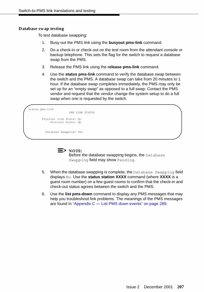
Issue 2 December 2001 207
Switch-to-PMS link translations and testing
Database swap testing
To test database swapping:
1. Busy-out the PMS link using the busyout pms-link command.
2. Do a check-in or check-out on the test room from the attendant console or backup telephone. This sets the flag for the switch to request a database swap from the PMS.
3. Release the PMS link using the release pms-link command.
4. Use the status pms-link command to verify the database swap between the switch and the PMS. A database swap can take from 20 minutes to 1 hour. If the database swap completes immediately, the PMS may only be set up for an “empty swap” as opposed to a full swap. Contact the PMS vendor and request that the vendor change the system setup to do a full swap when one is requested by the switch.
NOTE:Before the database swapping begins, the Database Swapping field may show Pending.
5. When the database swapping is complete, the Database Swapping field displays No. Use the status station XXXX command (where XXXX is a guest room number) on a few guest rooms to confirm that the check-in and check-out status agrees between the switch and the PMS.
6. Use the list pms-down command to display any PMS messages that may help you troubleshoot link problems. The meanings of the PMS messages are found in “Appendix C — List PMS down events” on page 289.
status pms-linkPMS LINK STATUS
Physical Link State: UpProtocol State: Up
Database Swapping? Yes
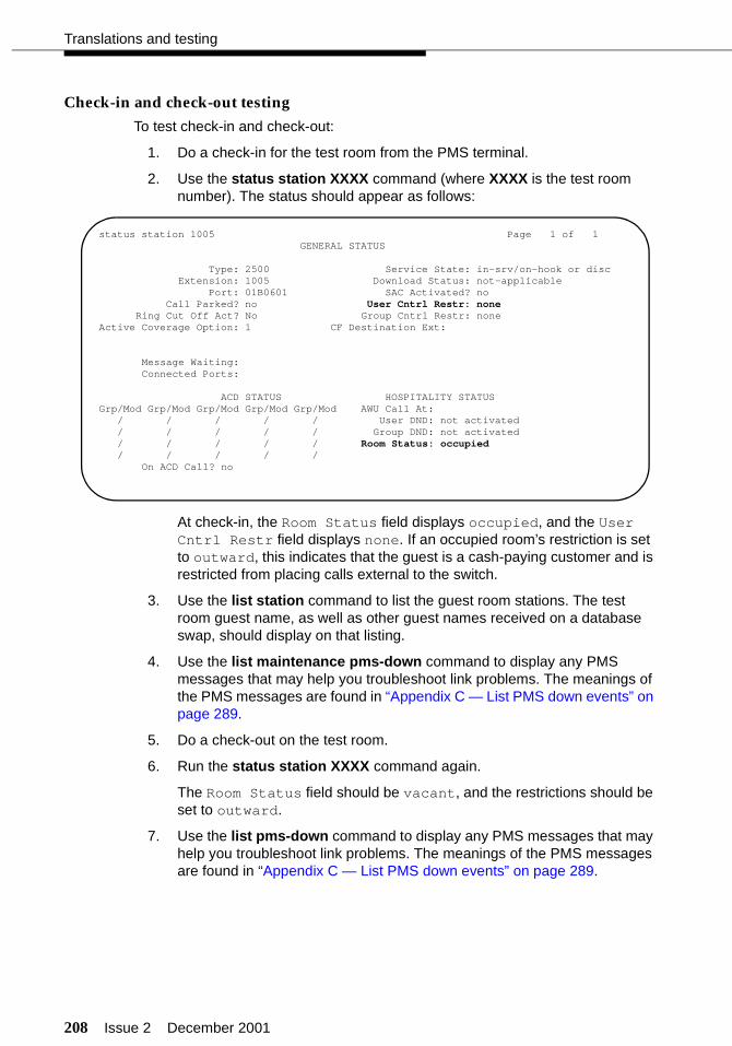
208 Issue 2 December 2001
Translations and testing
Check-in and check-out testing
To test check-in and check-out:
1. Do a check-in for the test room from the PMS terminal.
2. Use the status station XXXX command (where XXXX is the test room number). The status should appear as follows:
At check-in, the Room Status field displays occupied, and the User Cntrl Restr field displays none. If an occupied room’s restriction is set to outward, this indicates that the guest is a cash-paying customer and is restricted from placing calls external to the switch.
3. Use the list station command to list the guest room stations. The test room guest name, as well as other guest names received on a database swap, should display on that listing.
4. Use the list maintenance pms-down command to display any PMS messages that may help you troubleshoot link problems. The meanings of the PMS messages are found in “Appendix C — List PMS down events” on page 289.
5. Do a check-out on the test room.
6. Run the status station XXXX command again.
The Room Status field should be vacant, and the restrictions should be set to outward.
7. Use the list pms-down command to display any PMS messages that may help you troubleshoot link problems. The meanings of the PMS messages are found in “Appendix C — List PMS down events” on page 289.
status station 1005 Page 1 of 1GENERAL STATUS
Type: 2500 Service State: in-srv/on-hook or discExtension: 1005 Download Status: not-applicable
Port: 01B0601 SAC Activated? noCall Parked? no User Cntrl Restr: none
Ring Cut Off Act? No Group Cntrl Restr: noneActive Coverage Option: 1 CF Destination Ext:
Message Waiting:Connected Ports:
ACD STATUS HOSPITALITY STATUSGrp/Mod Grp/Mod Grp/Mod Grp/Mod Grp/Mod AWU Call At:
/ / / / / User DND: not activated/ / / / / Group DND: not activated/ / / / / Room Status: occupied/ / / / /
On ACD Call? no
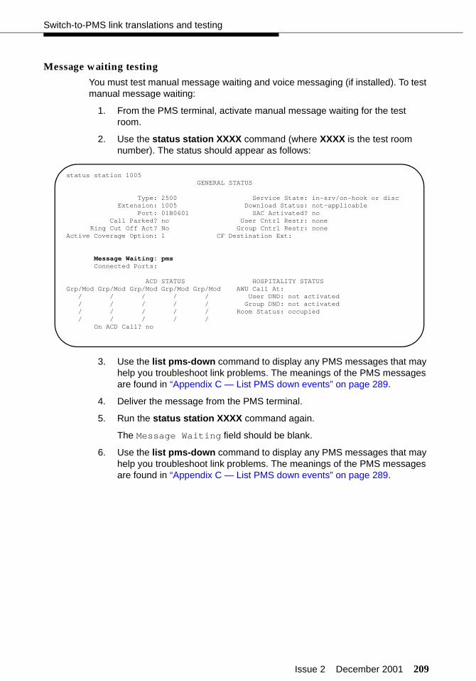
Issue 2 December 2001 209
Switch-to-PMS link translations and testing
Message waiting testing
You must test manual message waiting and voice messaging (if installed). To test manual message waiting:
1. From the PMS terminal, activate manual message waiting for the test room.
2. Use the status station XXXX command (where XXXX is the test room number). The status should appear as follows:
3. Use the list pms-down command to display any PMS messages that may help you troubleshoot link problems. The meanings of the PMS messages are found in “Appendix C — List PMS down events” on page 289.
4. Deliver the message from the PMS terminal.
5. Run the status station XXXX command again.
The Message Waiting field should be blank.
6. Use the list pms-down command to display any PMS messages that may help you troubleshoot link problems. The meanings of the PMS messages are found in “Appendix C — List PMS down events” on page 289.
status station 1005GENERAL STATUS
Type: 2500 Service State: in-srv/on-hook or discExtension: 1005 Download Status: not-applicable
Port: 01B0601 SAC Activated? noCall Parked? no User Cntrl Restr: none
Ring Cut Off Act? No Group Cntrl Restr: noneActive Coverage Option: 1 CF Destination Ext:
Message Waiting: pmsConnected Ports:
ACD STATUS HOSPITALITY STATUSGrp/Mod Grp/Mod Grp/Mod Grp/Mod Grp/Mod AWU Call At:
/ / / / / User DND: not activated/ / / / / Group DND: not activated/ / / / / Room Status: occupied/ / / / /
On ACD Call? no

210 Issue 2 December 2001
Translations and testing
To test voice messaging by retrieving the message from the test room:
1. Call the test room.
2. Leave a message after the greeting and tone.
3. Use the status station XXXX command (where XXXX is the test room number). The status should appear as follows:
4. Use the list pms-down command to display any PMS messages that may help you troubleshoot link problems. The meanings of the PMS messages are found in “Appendix C — List PMS down events” on page 289.
5. From the test room, call the voice messaging system. You will hear “Welcome to the guest voice mail system. You have one new message.” Listen to the message, and then delete the message.
6. Run the status station XXXX command again.
The Message Waiting field should be blank.
7. Use the list pms-down command to display any PMS messages that may help you troubleshoot link problems. The meanings of the PMS messages are found in “Appendix C — List PMS down events” on page 289.
status station 1005GENERAL STATUS
Type: 2500 Service State: in-srv/on-hook or discExtension: 1005 Download Status: not-applicable
Port: 01B0601 SAC Activated? noCall Parked? no User Cntrl Restr: none
Ring Cut Off Act? No Group Cntrl Restr: noneActive Coverage Option: 1 CF Destination Ext:
Message Waiting: audixConnected Ports:
ACD STATUS HOSPITALITY STATUSGrp/Mod Grp/Mod Grp/Mod Grp/Mod Grp/Mod AWU Call At:
/ / / / / User DND: not activated/ / / / / Group DND: not activated/ / / / / Room Status: occupied/ / / / /
On ACD Call? no

Issue 2 December 2001 211
Switch-to-PMS link translations and testing
To test voice messaging by retrieving the message from the attendant console:
1. Call the test room.
2. Leave another message after the greeting and tone.
3. Use the status station XXXX command (where XXXX is the test room number). The status should appear as follows:
4. Use the list pms-down command to display any PMS messages that may help you troubleshoot link problems. The meanings of the PMS messages are found in “Appendix C — List PMS down events” on page 289.
5. From the attendant console or backup telephone, call the voice messaging system. You will hear “Please enter your room extension.” Enter the test room extension. You will hear “You have one new voice mail message.” Listen to the message, and then delete the message.
6. Run the status station XXXX command again.
The Message Waiting field should be blank.
7. Use the list pms-down command to display any PMS messages that may help you troubleshoot link problems. The meanings of the PMS messages are found in “Appendix C — List PMS down events” on page 289.
status station 1005GENERAL STATUS
Type: 2500 Service State: in-srv/on-hook or discExtension: 1005 Download Status: not-applicable
Port: 01B0601 SAC Activated? noCall Parked? no User Cntrl Restr: none
Ring Cut Off Act? No Group Cntrl Restr: noneActive Coverage Option: 1 CF Destination Ext:
Message Waiting: audixConnected Ports:
ACD STATUS HOSPITALITY STATUSGrp/Mod Grp/Mod Grp/Mod Grp/Mod Grp/Mod AWU Call At:
/ / / / / User DND: not activated/ / / / / Group DND: not activated/ / / / / Room Status: occupied/ / / / /
On ACD Call? no
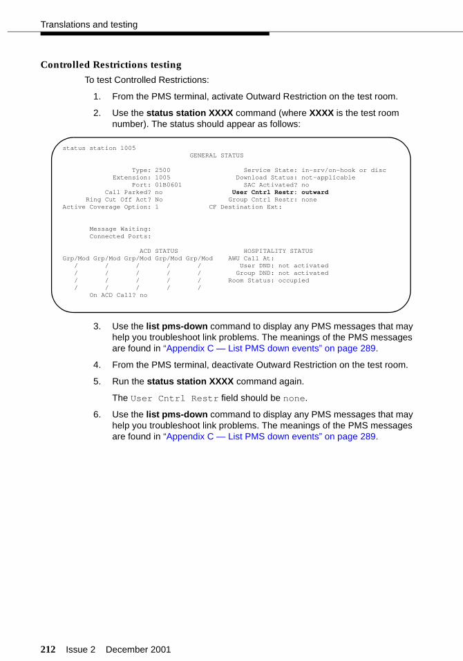
212 Issue 2 December 2001
Translations and testing
Controlled Restrictions testing
To test Controlled Restrictions:
1. From the PMS terminal, activate Outward Restriction on the test room.
2. Use the status station XXXX command (where XXXX is the test room number). The status should appear as follows:
3. Use the list pms-down command to display any PMS messages that may help you troubleshoot link problems. The meanings of the PMS messages are found in “Appendix C — List PMS down events” on page 289.
4. From the PMS terminal, deactivate Outward Restriction on the test room.
5. Run the status station XXXX command again.
The User Cntrl Restr field should be none.
6. Use the list pms-down command to display any PMS messages that may help you troubleshoot link problems. The meanings of the PMS messages are found in “Appendix C — List PMS down events” on page 289.
status station 1005GENERAL STATUS
Type: 2500 Service State: in-srv/on-hook or discExtension: 1005 Download Status: not-applicable
Port: 01B0601 SAC Activated? noCall Parked? no User Cntrl Restr: outward
Ring Cut Off Act? No Group Cntrl Restr: noneActive Coverage Option: 1 CF Destination Ext:
Message Waiting: Connected Ports:
ACD STATUS HOSPITALITY STATUSGrp/Mod Grp/Mod Grp/Mod Grp/Mod Grp/Mod AWU Call At:
/ / / / / User DND: not activated/ / / / / Group DND: not activated/ / / / / Room Status: occupied/ / / / /
On ACD Call? no
Issue 2 December 2001 213
Switch-to-PMS link translations and testing
Housekeeping status testing
To verify that the housekeeping status is updated:
1. Using a telephone in the test room, update the housekeeping status. If the PMS confirms the status change within 4 seconds, you will hear confirmation tone. If the status was not accepted, you will hear reorder tone. If you dialed an invalid code, you will hear intercept tone.
2. Verify that the status changed at the PMS terminal. You can also check the housekeeping status from the attendant console.
3. Use the list pms-down command to display any PMS messages that may help you troubleshoot link problems. The meanings of the PMS messages are found in “Appendix C — List PMS down events” on page 289.
4. At a telephone designated for housekeeping updates, update the housekeeping status for the test room. If the PMS confirms the status change within 4 seconds, you will hear confirmation tone. If the status was not accepted, you will hear reorder tone. If you dialed an invalid code, you will hear intercept tone.
5. Verify that the status changed at the PMS terminal. You can also check the housekeeping status from the attendant console.
Provide a list of feature access codes and housekeeping status codes to the customer and the PMS vendor.

214 Issue 2 December 2001
Translations and testing
Switch-to-voice messaging translations and testing
Table 12 is a checklist of the translations and tests that must be done to administer the switch-to-voice messaging link.
Switch-to-voice messaging link
There are three ways you can set up the messaging link between the switch and the voice messaging system:
■ “TCP/IP signaling” on page 215 (this is the only method used with the InnLine 2020 system)
■ “X.25 signaling” on page 231
■ “Mode Code Integration” on page 238
This link requires administration on the switch and the voice messaging system.
Table 12. Checklist for Switch-to-voice messaging translations
✔ Description
Switch-to-voice messaging link — Depending on the hardware, use only one of these three configurations:- “TCP/IP signaling” on page 215- “X.25 signaling” on page 231- “Mode Code Integration” on page 238
“Voice ports (switch)” on page 240
“Hunt groups for voice ports (switch)” on page 243
“Extensions for guest message retrieval (switch)” on page 245
“Call Coverage path (switch)” on page 246
“INTUITY AUDIX voice ports (INTUITY)” on page 247
“Services to phone number mapping (INTUITY)” on page 249
“Attendant and administrator passwords (INTUITY)” on page 250
“Testing the switch-to-INTUITY voice ports” on page 251
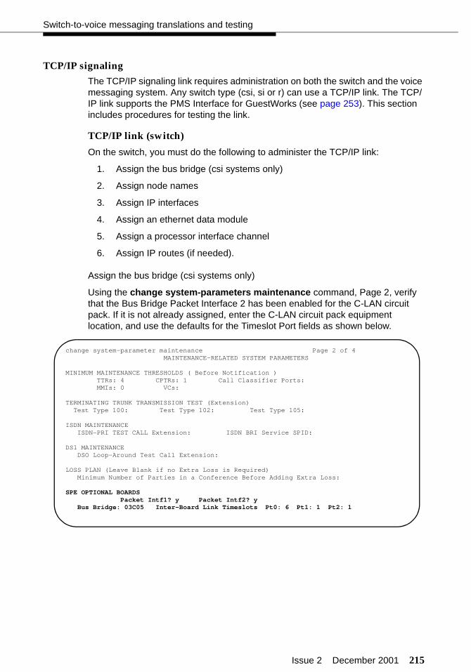
Issue 2 December 2001 215
Switch-to-voice messaging translations and testing
TCP/IP signaling
The TCP/IP signaling link requires administration on both the switch and the voice messaging system. Any switch type (csi, si or r) can use a TCP/IP link. The TCP/IP link supports the PMS Interface for GuestWorks (see page 253). This section includes procedures for testing the link.
TCP/IP link (switch)
On the switch, you must do the following to administer the TCP/IP link:
1. Assign the bus bridge (csi systems only)
2. Assign node names
3. Assign IP interfaces
4. Assign an ethernet data module
5. Assign a processor interface channel
6. Assign IP routes (if needed).
Assign the bus bridge (csi systems only)
Using the change system-parameters maintenance command, Page 2, verify that the Bus Bridge Packet Interface 2 has been enabled for the C-LAN circuit pack. If it is not already assigned, enter the C-LAN circuit pack equipment location, and use the defaults for the Timeslot Port fields as shown below.
change system-parameter maintenance Page 2 of 4MAINTENANCE-RELATED SYSTEM PARAMETERS
MINIMUM MAINTENANCE THRESHOLDS ( Before Notification )TTRs: 4 CPTRs: 1 Call Classifier Ports:MMIs: 0 VCs:
TERMINATING TRUNK TRANSMISSION TEST (Extension)Test Type 100: Test Type 102: Test Type 105:
ISDN MAINTENANCEISDN-PRI TEST CALL Extension: ISDN BRI Service SPID:
DS1 MAINTENANCEDSO Loop-Around Test Call Extension:
LOSS PLAN (Leave Blank if no Extra Loss is Required)Minimum Number of Parties in a Conference Before Adding Extra Loss:
SPE OPTIONAL BOARDSPacket Intf1? y Packet Intf2? y
Bus Bridge: 03C05 Inter-Board Link Timeslots Pt0: 6 Pt1: 1 Pt2: 1
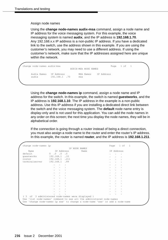
216 Issue 2 December 2001
Translations and testing
Assign node names
Using the change node-names audix-msa command, assign a node name and IP address for the voice messaging system. For this example, the voice messaging system is named audix, and the IP address is 192.168.1.70. Any 192.168.x.x IP address is a non-public IP address. If you have a dedicated link to the switch, use the address shown in this example. If you are using the customer’s network, you may need to use a different address. If using the customer’s network, make sure that the IP addresses assigned here are unique within the network.
Using the change node-names ip command, assign a node name and IP address for the switch. In this example, the switch is named guestworks, and the IP address is 192.168.1.10. The IP address in the example is a non-public address. Use this IP address if you are installing a dedicated direct link between the switch and the voice messaging system. The default node name entry is display-only and is not used for this application. You can add the node names in any order on this screen; the next time you display the node names, they will be in alphabetical order.
If the connection is going through a router instead of being a direct connection, you must also assign a node name to the router and enter the router’s IP address. In this example, the router is named router, and the IP address is 192.168.1.211.
change node-names audix-msa Page 1 of 1AUDIX-MSA NODE NAMES
Audix Names IP Address MSA Names IP Addressaudix 192.168.1 .70 msa
change node-names ip Page 1 of 1IP NODE NAMES
Name IP Address Name IP Addressdefault 0 .0 .0 .0 . . .guestworks 192.168.1 .10 . . .router 192.168.1 .211 . . .terminalserver 192.168.1 .99 . . .
. . . . . . . . . . . . . . . . . . . . . . . . . . . . . . . . . . . . . . . . . . . . . . . . . . . . . . . . . . . . . . . . . . . . . . . .
( 3 of 3 administered node-names were displayed )Use ‘list node-names’ command to see all the administered node-namesUse ‘change node-names ip xxx’ to change a node-name ‘xxx’ or add a node-name
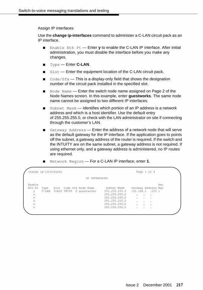
Issue 2 December 2001 217
Switch-to-voice messaging translations and testing
Assign IP interfaces
Use the change ip-interfaces command to administer a C-LAN circuit pack as an IP interface.
■ Enable Eth Pt — Enter y to enable the C-LAN IP interface. After initial administration, you must disable the interface before you make any changes.
■ Type — Enter C-LAN.
■ Slot — Enter the equipment location of the C-LAN circuit pack.
■ Code/Sfx — This is a display-only field that shows the designation number of the circuit pack installed in the specified slot.
■ Node Name — Enter the switch node name assigned on Page 2 of the Node Names screen. In this example, enter guestworks. The same node name cannot be assigned to two different IP interfaces.
■ Subnet Mask — Identifies which portion of an IP address is a network address and which is a host identifier. Use the default entry of 255.255.255.0, or check with the LAN administrator on site if connecting through the customer’s LAN.
■ Gateway Address — Enter the address of a network node that will serve as the default gateway for the IP interface. If the application goes to points off the subnet, a gateway address of the router is required. If the switch and the INTUITY are on the same subnet, a gateway address is not required. If using ethernet only, and a gateway address is administered, no IP routes are required.
■ Network Region — For a C-LAN IP interface, enter 1.
change ip-interfaces Page 1 of 4
IP INTERFACES
Enable NetEth Pt Type Slot Code Sfx Node Name Subnet Mask Gateway Address Rgn
y C-LAN 01A02 TN799 D guestworks 255.255.255.0 192.168.1 .255 1n 255.255.255.0 . . .n 255.255.255.0 . . .n 255.255.255.0 . . .n 255.255.255.0 . . .n 255.255.255.0 . . .

218 Issue 2 December 2001
Translations and testing
Assign an ethernet data module
Use the add data-module command to administer an ethernet data module. If you are changing options on an existing data module, you must disable the link before you make any changes.
■ Data Extension — Use an unassigned extension number.
■ Type — Enter ethernet.
■ Port — Enter the equipment location of the C-LAN circuit pack. For the ethernet link, you will always use circuit number 17.
■ Link — Select a TCP/IP link number (1-25 for csi/si, 1-33 for r). For most systems, use link 1. This entry is also used on the Processor Channel screen.
■ Name — Enter a name for the data module. This name will display when you list the assigned data modules.
■ BCC — A display-only field.
■ Network uses 1’s for Broadcast Address — This sets the host portion of the IP address to 0’s or 1’s. The default is yes (all 1’s). Use the default for this installation.
add data-module 2000 Page 1 of 1DATA MODULE
Data Extension: 2000 Name: ethernet data moduleType: ethernetPort: 01A0217Link: 1
Network uses 1’s for Broadcast Addresses? y

Issue 2 December 2001 219
Switch-to-voice messaging translations and testing
Assign a processor interface channel
Use the change communication-interface processor-channels command to assign a processor interface channel.
■ Proc Chan — Select a processor channel for this link. Use the first channel available.
■ Enable — Enter y.
■ Appl — Enter audix.
■ Gtwy To — Not used for the voice messaging application.
■ Mode — Enter s (for server).
■ Interface Link — Enter the TCP/IP link number used on the ethernet data module screen. For this series of examples, link 1 was used.
■ Interface Chan — Enter the TCP channel number (5002 or 6001-6999). This must match the TCP Port field of the INTUITY Switch Interface Administration screen. The recommended entry for a voice messaging system is 5002.
■ Destination Node — Enter the node name for the voice messaging system as assigned on the Node Names screen. In these examples, audix is used.
■ Destination Port — Use the default of 0.
■ Session Local — Enter 1. This field must match the Local Node Number field on the switch dial plan.
■ Session Remote — Enter 1. This field must match the AUDIX Number field on the INTUITY Switch Interface Administration screen.
■ Mach ID — Enter 1. This field must match the AUDIX Number field on the INTUITY Switch Interface Administration screen.
change communication-interface processor-channels Page 1 of 8PROCESSOR CHANNEL ASSIGNMENT
Proc Gtwy Interface Destination Session MachChan Enable Appl. To Mode Link/Chan Node Port Local/Remote ID
1: y audix s 1 5002 audix 0 1 1 12: n3: n
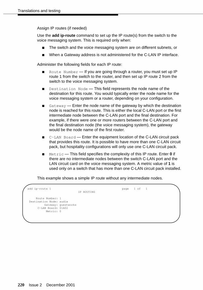
220 Issue 2 December 2001
Translations and testing
Assign IP routes (if needed)
Use the add ip-route command to set up the IP route(s) from the switch to the voice messaging system. This is required only when:
■ The switch and the voice messaging system are on different subnets, or
■ When a Gateway address is not administered for the C-LAN IP interface.
Administer the following fields for each IP route:
■ Route Number — If you are going through a router, you must set up IP route 1 from the switch to the router, and then set up IP route 2 from the switch to the voice messaging system.
■ Destination Node — This field represents the node name of the destination for this route. You would typically enter the node name for the voice messaging system or a router, depending on your configuration.
■ Gateway — Enter the node name of the gateway by which the destination node is reached for this route. This is either the local C-LAN port or the first intermediate node between the C-LAN port and the final destination. For example, if there were one or more routers between the C-LAN port and the final destination node (the voice messaging system), the gateway would be the node name of the first router.
■ C-LAN Board — Enter the equipment location of the C-LAN circuit pack that provides this route. It is possible to have more than one C-LAN circuit pack, but hospitality configurations will only use one C-LAN circuit pack.
■ Metric — This field specifies the complexity of this IP route. Enter 0 if there are no intermediate nodes between the switch C-LAN port and the LAN circuit card on the voice messaging system. A metric value of 1 is used only on a switch that has more than one C-LAN circuit pack installed.
This example shows a simple IP route without any intermediate nodes.
add ip-route 1 page 1 of 1IP ROUTING
Route Number: 1Destination Node: audix
Gateway: guestworksC-LAN Board: 01A02
Metric: 0
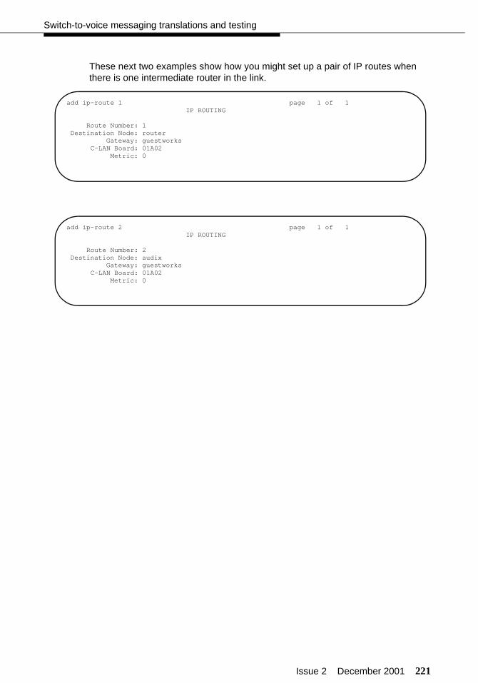
Issue 2 December 2001 221
Switch-to-voice messaging translations and testing
These next two examples show how you might set up a pair of IP routes when there is one intermediate router in the link.
add ip-route 1 page 1 of 1IP ROUTING
Route Number: 1Destination Node: router
Gateway: guestworksC-LAN Board: 01A02
Metric: 0
add ip-route 2 page 1 of 1IP ROUTING
Route Number: 2Destination Node: audix
Gateway: guestworksC-LAN Board: 01A02
Metric: 0
222 Issue 2 December 2001
Translations and testing
TCP/IP link (INTUITY)
On the INTUITY, you must do the following for the TCP/IP link:
■ Administer the link mode
■ Administer the TCP/IP networking
NOTE:Before you can administer the TCP/IP networking, the TCP/IP feature must be enabled on the customer features window. Technical support must dial in and enable TCP/IP if it is not enabled.
■ Configure the LAN circuit card
■ Select a switch type (R4.4 only)
■ Administer the switch interface
■ Reboot the INTUITY system (R4.4 only).
Administer the link mode
Use the Customer/Services Administration > System Management > System Control > PMS Interface Administration command to administer the link mode (GuestWorks or standalone).
Administer the TCP/IP networking (R4.4)
Use the Networking Administration > TCP/IP Administration command to access the TCP/IP administration.
NOTE:If this administration is already complete, verify that the settings are accurate for your installation.
■ UNIX Machine Name — Enter the UNIX name for the INTUITY system. This name is case-sensitive.
■ IP Address — Enter the IP address for the INTUITY system. From the previous examples, use 192.168.1.70 if using a dedicated private link.
■ Subnet Mask — Use the default of 255.255.255.0.
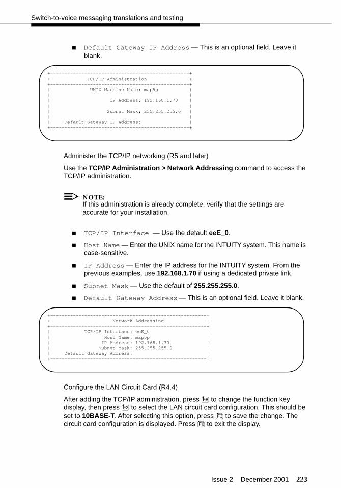
Issue 2 December 2001 223
Switch-to-voice messaging translations and testing
■ Default Gateway IP Address — This is an optional field. Leave it blank.
Administer the TCP/IP networking (R5 and later)
Use the TCP/IP Administration > Network Addressing command to access the TCP/IP administration.
NOTE:If this administration is already complete, verify that the settings are accurate for your installation.
■ TCP/IP Interface — Use the default eeE_0.
■ Host Name — Enter the UNIX name for the INTUITY system. This name is case-sensitive.
■ IP Address — Enter the IP address for the INTUITY system. From the previous examples, use 192.168.1.70 if using a dedicated private link.
■ Subnet Mask — Use the default of 255.255.255.0.
■ Default Gateway Address — This is an optional field. Leave it blank.
Configure the LAN Circuit Card (R4.4)
After adding the TCP/IP administration, press to change the function key display, then press to select the LAN circuit card configuration. This should be set to 10BASE-T. After selecting this option, press to save the change. The circuit card configuration is displayed. Press to exit the display.
+-------------------------------------------------++ TCP/IP Administration ++-------------------------------------------------+| UNIX Machine Name: map5p || || IP Address: 192.168.1.70 || || Subnet Mask: 255.255.255.0 || || Default Gateway IP Address: |+-------------------------------------------------+
+-------------------------------------------------------++ Network Addressing ++-------------------------------------------------------+| TCP/IP Interface: eeE_0 || Host Name: map5p || IP Address: 192.168.1.70 || Subnet Mask: 255.255.255.0 || Default Gateway Address: |+-------------------------------------------------------+
F8
F2
F3
F6

224 Issue 2 December 2001
Translations and testing
Configure the LAN circuit card (R5 and later)
After adding the TCP/IP administration, press to return to the INTUITY Main Menu. Use the TCP/IP Administration > Network Interface Card Set-up command.
■ Card Type — Set this field to PRO100B.
■ Network Media Type — Set this field to Auto-Detect.
After setting these options, press to save the change.
Select a switch type (R4.4 only)
Use the Switch Interface Administration > Switch Selection command to access the switch selection administration.
■ Country — Enter the country where this system is installed.
■ Switch — Enter DEFINITY OVERLAN.
Administer the switch interface (R4.4 and R5)
Use the Switch Interface Administration > Call Data Interface Administration > Switch Link Administration command to access the switch link administration.
■ Extension Length — Enter the extension length from the switch dial plan.
■ Host Switch Number — Enter 1.
■ AUDIX Number — Enter 1. This must match the Machine ID setting on the Processor Channel screen.
■ Switch Number — Enter 1.
F6
F3
+-------------------------------------------------++ Switch Selection ++-------------------------------------------------+| || || || Country: UNITED STATES || || || || Switch: DEFINITY OVERLAN || || || |+-------------------------------------------------+
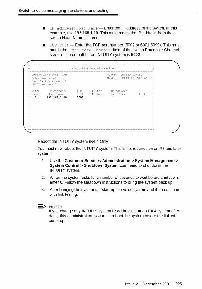
Issue 2 December 2001 225
Switch-to-voice messaging translations and testing
■ IP Address/Host Name — Enter the IP address of the switch. In this example, use 192.168.1.10. This must match the IP address from the switch Node Names screen.
■ TCP Port — Enter the TCP port number (5002 or 6001-6999). This must match the Interface Channel field of the switch Processor Channel screen. The default for an INTUITY system is 5002.
Reboot the INTUITY system (R4.4 Only)
You must now reboot the INTUITY system. This is not required on an R5 and later system.
1. Use the Customer/Services Administration > System Management > System Control > Shutdown System command to shut down the INTUITY system.
2. When the system asks for a number of seconds to wait before shutdown, enter 0. Follow the shutdown instructions to bring the system back up.
3. After bringing the system up, start up the voice system and then continue with link testing.
NOTE:If you change any INTUITY system IP addresses on an R4.4 system after doing this administration, you must reboot the system before the link will come up.
+-------------------------------------------------------------------------++ Switch Link Administration ++-------------------------------------------------------------------------+| Switch Link Type: LAN Country: UNITED STATES || Extension Length: 3 Switch: DEFINITY OVERLAN || Host Switch Number: 1 || AUDIX Number: 1 || ||Switch IP Address/ TCP Switch IP Address/ TCP ||Number Host Name Port Number Host Name Port || 1 192.168.1.10 5002 || || || || || || || || || |+-------------------------------------------------------------------------+
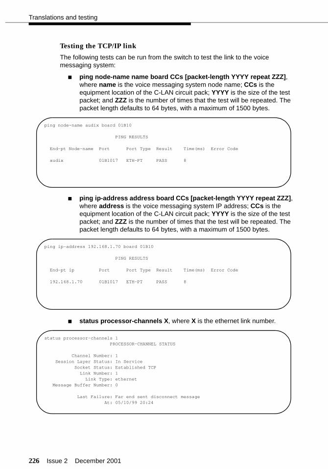
226 Issue 2 December 2001
Translations and testing
Testing the TCP/IP link
The following tests can be run from the switch to test the link to the voice messaging system:
■ ping node-name name board CCs [packet-length YYYY repeat ZZZ], where name is the voice messaging system node name; CCs is the equipment location of the C-LAN circuit pack; YYYY is the size of the test packet; and ZZZ is the number of times that the test will be repeated. The packet length defaults to 64 bytes, with a maximum of 1500 bytes.
■ ping ip-address address board CCs [packet-length YYYY repeat ZZZ], where address is the voice messaging system IP address; CCs is the equipment location of the C-LAN circuit pack; YYYY is the size of the test packet; and ZZZ is the number of times that the test will be repeated. The packet length defaults to 64 bytes, with a maximum of 1500 bytes.
■ status processor-channels X, where X is the ethernet link number.
ping node-name audix board 01B10
PING RESULTS
End-pt Node-name Port Port Type Result Time(ms) Error Code
audix 01B1017 ETH-PT PASS 8
ping ip-address 192.168.1.70 board 01B10
PING RESULTS
End-pt ip Port Port Type Result Time(ms) Error Code
192.168.1.70 01B1017 ETH-PT PASS 8
status processor-channels 1PROCESSOR-CHANNEL STATUS
Channel Number: 1Session Layer Status: In Service
Socket Status: Established TCPLink Number: 1
Link Type: ethernetMessage Buffer Number: 0
Last Failure: Far end sent disconnect messageAt: 05/10/99 20:24
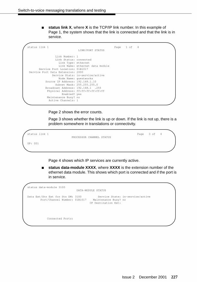
Issue 2 December 2001 227
Switch-to-voice messaging translations and testing
■ status link X, where X is the TCP/IP link number. In this example of Page 1, the system shows that the link is connected and that the link is in service.
Page 2 shows the error counts.
Page 3 shows whether the link is up or down. If the link is not up, there is a problem somewhere in translations or connectivity.
Page 4 shows which IP services are currently active.
■ status data-module XXXX, where XXXX is the extension number of the ethernet data module. This shows which port is connected and if the port is in service.
status link 1 Page 1 of 4LINK/PORT STATUS
Link Number: 1Link Status: connected
Link Type: ethernetLink Name: ethernet data module
Service Port Location: 01B1017Service Port Data Extension: 2000
Service Stats: in-service/activeNode Name: guestworks
Source IP Address: 192.168.1.10Subnet Mask: 255.255.255.0
Broadcast Address: 192.168.1 .255Physical Address: ff:ff:ff:ff:ff:ff
Enabled? yesMaintenance Busy? noActive Channels: 1
status link 1 Page 3 of 4PROCESSOR CHANNEL STATUS
UP: 001
status data-module 3100DATA-MODULE STATUS
Data Ext/Stn Ext for Stn DM: 3100 Service State: in-service/activePort/Channel Number: 01B1017 Maintenance Busy? no
CF Destination Ext:
Connected Ports:
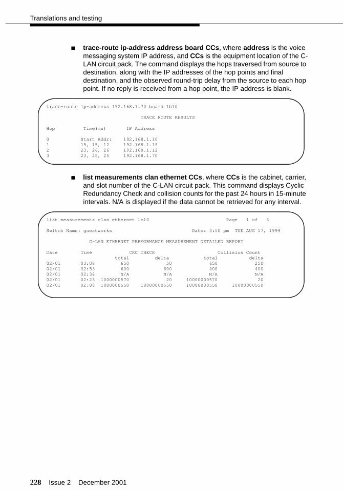
228 Issue 2 December 2001
Translations and testing
■ trace-route ip-address address board CCs, where address is the voice messaging system IP address, and CCs is the equipment location of the C-LAN circuit pack. The command displays the hops traversed from source to destination, along with the IP addresses of the hop points and final destination, and the observed round-trip delay from the source to each hop point. If no reply is received from a hop point, the IP address is blank.
■ list measurements clan ethernet CCs, where CCs is the cabinet, carrier, and slot number of the C-LAN circuit pack. This command displays Cyclic Redundancy Check and collision counts for the past 24 hours in 15-minute intervals. N/A is displayed if the data cannot be retrieved for any interval.
trace-route ip-address 192.168.1.70 board 1b10
TRACE ROUTE RESULTS
Hop Time(ms) IP Address
0 Start Addr: 192.168.1.101 15, 15, 12 192.168.1.152 23, 26, 26 192.168.1.123 23, 25, 25 192.168.1.70
list measurements clan ethernet 1b10 Page 1 of 3
Switch Name: guestworks Date: 3:50 pm TUE AUG 17, 1999
C-LAN ETHERNET PERMORMANCE MEASUREMENT DETAILED REPORT
Date Time CRC CHECK Collision Counttotal delta total delta
02/01 03:08 650 50 650 25002/01 02:53 600 600 400 40002/01 02:38 N/A N/A N/A N/A02/01 02:23 1000000570 20 10000000570 2002/01 02:08 1000000550 10000000550 10000000550 10000000550

Issue 2 December 2001 229
Switch-to-voice messaging translations and testing
The following tests can be run from the INTUITY system to test the link to the switch:
■ Customer/Services Administration > Diagnostics > Switch Link Diagnostics > Link Diagnostics
This screen is an example of a TCP/IP link. It shows the link being in service.
If the link status and session status show DOWN, use the following function keys to test the link:
— tests to see if the link is electrically connected. Run this test first. If it fails, check the cabling.
— resets the link. After finished, press to refresh the link. If it still does not come up, check the switch and INTUITY system adminis-tration.
You can also press to change the function key labels and use the following to control the status of the link:
— busies-out the link
— releases the link from busy-out.
■ Customer/Services Administration > Diagnostics > Switch Link Diagnostics > Session Layer Diagnostics
Press every few seconds to see if the sequence numbers increment. If the numbers do not increment, data transfer is not taking place.
+------------------------------------------------------------------------++ Link Diagnostics ++------------------------------------------------------------------------+| Switch Link Type: LAN Country: UNITED STATES || Switch: DEFINITY OVERLAN || || || Switch Link Session Switch Link Session || Number Status Status Number Status Status || 1 UP UP || | +------------------------------------------------------------------------+
F3
F2 F5
F8
F2
F3
+------------------------------------------------------------------------------++ Session Layer ++------------------------------------------------------------------------------+| Switch Link Type: LAN Country: UNITED STATES || Switch: DEFINITY OVERLAN || || Transmit Receive Transmit Receive || Switch Session Sequence Sequence Switch Session Sequence Sequence|| Number State Number Number Number State Number Number || 1 DATA 148 45 || |+------------------------------------------------------------------------------+
F5

230 Issue 2 December 2001
Translations and testing
■ Customer/Services Administration > Diagnostics > TCP/IP Diagnostics > Send & Receive Test Packets
After entering the switch IP address, press to start the test. This sends test packets between the INTUITY and the switch. The system tests to see whether all the packets are transmitted and whether they are transmitted in the correct sequence. If there is high (greater than 10%) packet loss, or if the packets are out of order, there may be network problems. While this test is running, the yellow T/R lamp on the LAN circuit card should be flashing.
■ Customer/Services Administration > Diagnostics > TCP/IP Diagnostics > View Packet Statistics
When using this command, you can select from a detailed report, an interfaces report (shown below), and a routing report.
Continue with “Voice ports (switch)” on page 240.
F3
+------------------------------------------------------------------------------++ Test Packet Results ++------------------------------------------------------------------------------+|72 bytes from 192.168.X.X: icmp_seq=0, time-0, ms ||72 bytes from 192.168.X.X: icmp_seq=1, time-0, ms ||72 bytes from 192.168.X.X: icmp_seq=2, time-0, ms ||72 bytes from 192.168.X.X: icmp_seq=3, time-0, ms ||72 bytes from 192.168.X.X: icmp_seq=4, time-0, ms ||72 bytes from 192.168.X.X: icmp_seq=5, time-0, ms ||72 bytes from 192.168.X.X: icmp_seq=6, time-0, ms ||72 bytes from 192.168.X.X: icmp_seq=7, time-0, ms ||72 bytes from 192.168.X.X: icmp_seq=8, time-0, ms ||72 bytes from 192.168.X.X: icmp_seq=9, time-0, ms || ||10 packets transmitted, 10 packets recieved, 0% packet loss ||round-trip (ms) min/arg/max=0/0/0 || ||Note: Hight packet loss, long round-trip time, or ||packets received out of order (icmp-swq) may ||indicate a network problem. || ||Press Enter to continue. |+------------------------------------------------------------------------------+
+------------------------------------------------------------------------------++ Packet Statistics ++------------------------------------------------------------------------------+| Name Mtu Network Address Ipkts Ierrs Opkts Oerrs Collis || sme0 1500 192.168.1 192.168.1.10 65827 0 48865 0 0 || ||Note: Abnormally high values in the Ierrs, Oerrs, ||or Collis column may indicate a network problem. || ||Press Enter to continue || |+------------------------------------------------------------------------------+
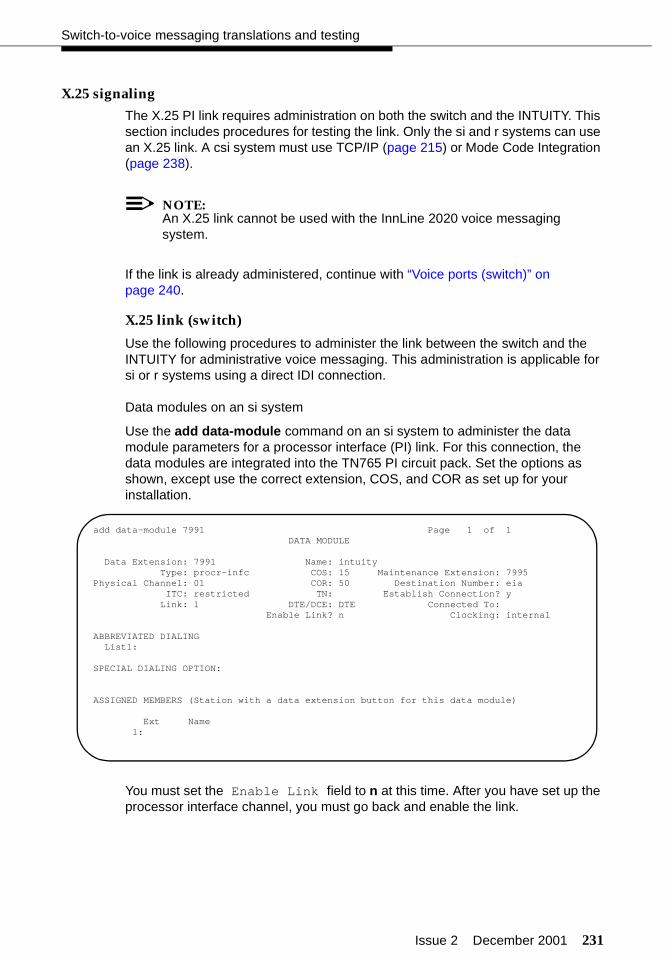
Issue 2 December 2001 231
Switch-to-voice messaging translations and testing
X.25 signaling
The X.25 PI link requires administration on both the switch and the INTUITY. This section includes procedures for testing the link. Only the si and r systems can use an X.25 link. A csi system must use TCP/IP (page 215) or Mode Code Integration (page 238).
NOTE:An X.25 link cannot be used with the InnLine 2020 voice messaging system.
If the link is already administered, continue with “Voice ports (switch)” on page 240.
X.25 link (switch)
Use the following procedures to administer the link between the switch and the INTUITY for administrative voice messaging. This administration is applicable for si or r systems using a direct IDI connection.
Data modules on an si system
Use the add data-module command on an si system to administer the data module parameters for a processor interface (PI) link. For this connection, the data modules are integrated into the TN765 PI circuit pack. Set the options as shown, except use the correct extension, COS, and COR as set up for your installation.
You must set the Enable Link field to n at this time. After you have set up the processor interface channel, you must go back and enable the link.
add data-module 7991 Page 1 of 1DATA MODULE
Data Extension: 7991 Name: intuityType: procr-infc COS: 15 Maintenance Extension: 7995
Physical Channel: 01 COR: 50 Destination Number: eiaITC: restricted TN: Establish Connection? y
Link: 1 DTE/DCE: DTE Connected To: Enable Link? n Clocking: internal
ABBREVIATED DIALINGList1:
SPECIAL DIALING OPTION:
ASSIGNED MEMBERS (Station with a data extension button for this data module)
Ext Name1:
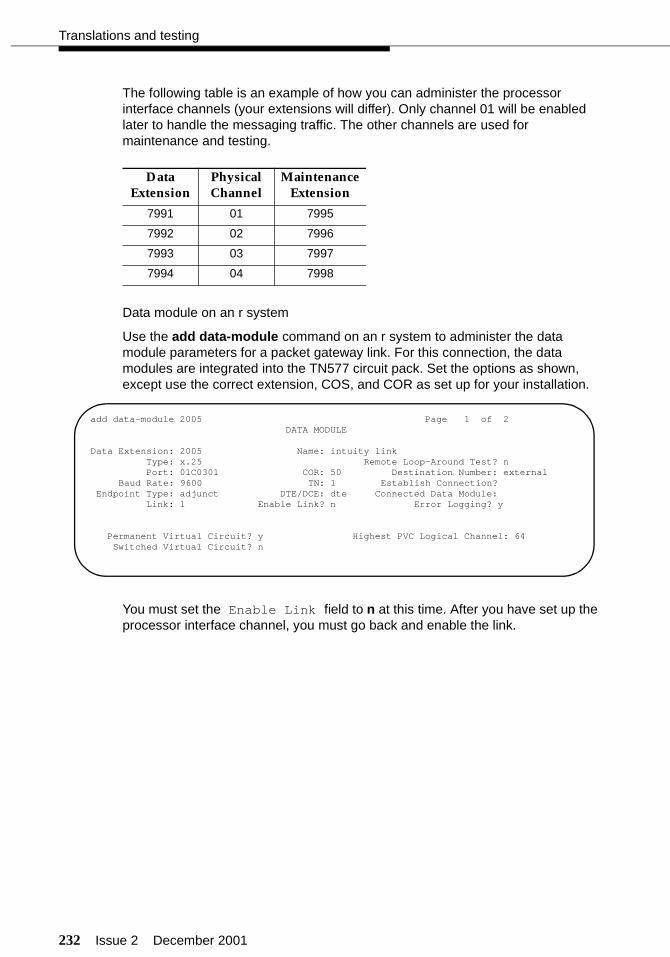
232 Issue 2 December 2001
Translations and testing
The following table is an example of how you can administer the processor interface channels (your extensions will differ). Only channel 01 will be enabled later to handle the messaging traffic. The other channels are used for maintenance and testing.
Data module on an r system
Use the add data-module command on an r system to administer the data module parameters for a packet gateway link. For this connection, the data modules are integrated into the TN577 circuit pack. Set the options as shown, except use the correct extension, COS, and COR as set up for your installation.
You must set the Enable Link field to n at this time. After you have set up the processor interface channel, you must go back and enable the link.
Data Extension
Physical Channel
Maintenance Extension
7991 01 7995
7992 02 7996
7993 03 7997
7994 04 7998
add data-module 2005 Page 1 of 2DATA MODULE
Data Extension: 2005 Name: intuity linkType: x.25 Remote Loop-Around Test? nPort: 01C0301 COR: 50 Destination Number: external
Baud Rate: 9600 TN: 1 Establish Connection?Endpoint Type: adjunct DTE/DCE: dte Connected Data Module:
Link: 1 Enable Link? n Error Logging? y
Permanent Virtual Circuit? y Highest PVC Logical Channel: 64Switched Virtual Circuit? n
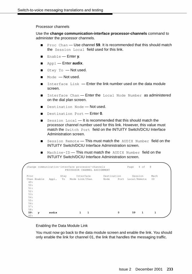
Issue 2 December 2001 233
Switch-to-voice messaging translations and testing
Processor channels
Use the change communication-interface processor-channels command to administer the processor channels.
■ Proc Chan — Use channel 59. It is recommended that this should match the Session Local field used for this link.
■ Enable — Enter y.
■ Appl — Enter audix.
■ Gtwy To — Not used.
■ Mode — Not used.
■ Interface Link — Enter the link number used on the data module screen.
■ Interface Chan — Enter the Local Node Number as administered on the dial plan screen.
■ Destination Node — Not used.
■ Destination Port — Enter 0.
■ Session Local — It is recommended that this should match the processor channel number used for this link. However, this value must match the Switch Port field on the INTUITY Switch/DCIU Interface Administration screen.
■ Session Remote — This must match the AUDIX Number field on the INTUITY Switch/DCIU Interface Administration screen.
■ Machine-ID — This must match the AUDIX Number field on the INTUITY Switch/DCIU Interface Administration screen.
Enabling the Data Module Link
You must now go back to the data module screen and enable the link. You should only enable the link for channel 01, the link that handles the messaging traffic.
change communication-interface processor-channels Page 4 of 8PROCESSOR CHANNEL ASSIGNMENT
Proc Gtwy Interface Destination Session MachChan Enable Appl. To Mode Link/Chan Node Port Local/Remote ID49:50:51:52:53:54:55:56:57:58:59: y audix 1 1 0 59 1 160:

234 Issue 2 December 2001
Translations and testing
X.25 link (INTUITY)
Checking the switch link
Use the Customer/Services Administration > Diagnostics > Switch Interface Diagnostics command to determine if the link is active. During initial installation, this screen should show that the link is busied out.
After pressing to change the function key labels, the following function keys control the status of the link:
■ busies-out the link
■ releases the link from busy-out
■ performs diagnostics on the link.
Select a switch type (R4.4 only)
Use the Switch Interface Administration > Switch Selection command to access the switch selection administration.
■ Country — Enter the country where this system is installed.
■ Switch — Enter Definity.
+------------------------------------------------------------------------------++ Diagnose Switch Link ++------------------------------------------------------------------------------+| STATUS SWITCH-LINK || || Type Baud State || DCIU 9600 Busied || || Link Level 2 is Down || || DCIU switches (In/Out of data transfer) || 1 2 3 4 5 6 7 8 9 10 11 12 13 14 15 16 17 18 19 20 || I |+------------------------------------------------------------------------------+
F8
F2
F3
F4
+-------------------------------------------------++ Switch Selection ++-------------------------------------------------+| || || || Country: UNITED STATES || || || || Switch: Definity || || || |+-------------------------------------------------+
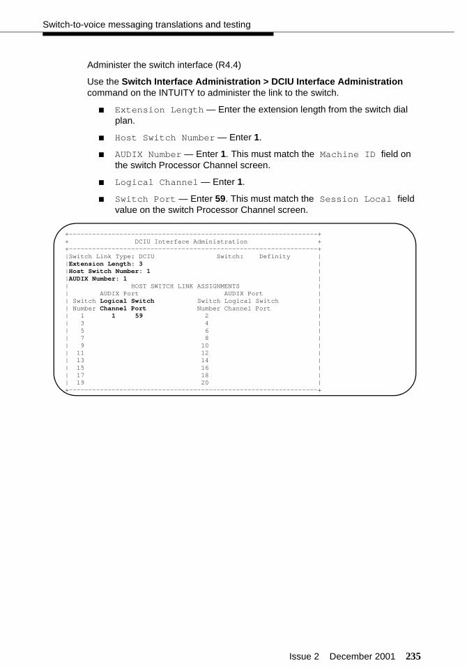
Issue 2 December 2001 235
Switch-to-voice messaging translations and testing
Administer the switch interface (R4.4)
Use the Switch Interface Administration > DCIU Interface Administration command on the INTUITY to administer the link to the switch.
■ Extension Length — Enter the extension length from the switch dial plan.
■ Host Switch Number — Enter 1.
■ AUDIX Number — Enter 1. This must match the Machine ID field on the switch Processor Channel screen.
■ Logical Channel — Enter 1.
■ Switch Port — Enter 59. This must match the Session Local field value on the switch Processor Channel screen.
+----------------------------------------------------------------++ DCIU Interface Administration ++----------------------------------------------------------------+|Switch Link Type: DCIU Switch: Definity ||Extension Length: 3 ||Host Switch Number: 1 ||AUDIX Number: 1 || HOST SWITCH LINK ASSIGNMENTS || AUDIX Port AUDIX Port || Switch Logical Switch Switch Logical Switch || Number Channel Port Number Channel Port || 1 1 59 2 || 3 4 || 5 6 || 7 8 || 9 10 || 11 12 || 13 14 || 15 16 || 17 18 || 19 20 |+----------------------------------------------------------------+
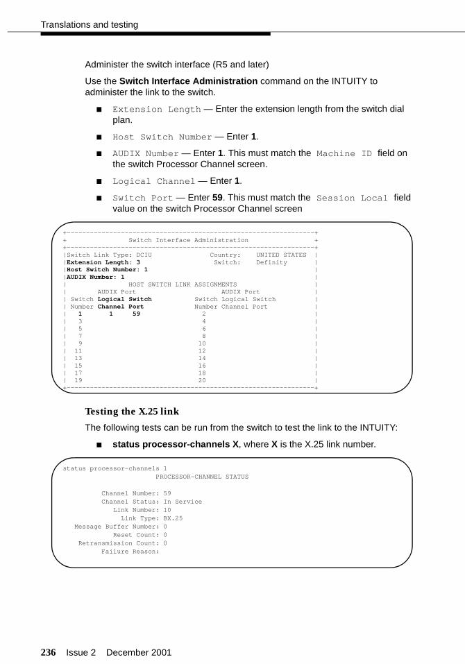
236 Issue 2 December 2001
Translations and testing
Administer the switch interface (R5 and later)
Use the Switch Interface Administration command on the INTUITY to administer the link to the switch.
■ Extension Length — Enter the extension length from the switch dial plan.
■ Host Switch Number — Enter 1.
■ AUDIX Number — Enter 1. This must match the Machine ID field on the switch Processor Channel screen.
■ Logical Channel — Enter 1.
■ Switch Port — Enter 59. This must match the Session Local field value on the switch Processor Channel screen
Testing the X.25 link
The following tests can be run from the switch to test the link to the INTUITY:
■ status processor-channels X, where X is the X.25 link number.
+----------------------------------------------------------------++ Switch Interface Administration ++----------------------------------------------------------------+|Switch Link Type: DCIU Country: UNITED STATES ||Extension Length: 3 Switch: Definity ||Host Switch Number: 1 ||AUDIX Number: 1 || HOST SWITCH LINK ASSIGNMENTS || AUDIX Port AUDIX Port || Switch Logical Switch Switch Logical Switch || Number Channel Port Number Channel Port || 1 1 59 2 || 3 4 || 5 6 || 7 8 || 9 10 || 11 12 || 13 14 || 15 16 || 17 18 || 19 20 |+----------------------------------------------------------------+
status processor-channels 1PROCESSOR-CHANNEL STATUS
Channel Number: 59Channel Status: In Service
Link Number: 10Link Type: BX.25
Message Buffer Number: 0Reset Count: 0
Retransmission Count: 0Failure Reason:
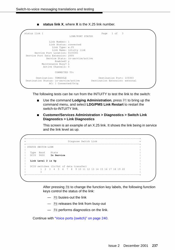
Issue 2 December 2001 237
Switch-to-voice messaging translations and testing
■ status link X, where X is the X.25 link number.
The following tests can be run from the INTUITY to test the link to the switch:
■ Use the command Lodging Administration, press to bring up the command menu, and select LDG/PMS Link Restart to restart the switch-to-INTUITY link.
■ Customer/Services Administration > Diagnostics > Switch Link Diagnostics > Link Diagnostics
This screen is an example of an X.25 link. It shows the link being in service and the link level as up.
After pressing to change the function key labels, the following function keys control the status of the link:
— busies-out the link
— releases the link from busy-out
— performs diagnostics on the link.
Continue with “Voice ports (switch)” on page 240.
status link 1 Page 1 of 3LINK/PORT STATUS
Link Number: 1Link Status: connected
Link Type: x.25Link Name: intuity link
Service Port Location: 01C0301Service Port Data Extension: 2005
Service Stats: in-service/activeEnabled? y
Maintenance Busy? nActive Channels: 0
CONNECTED TO:
Destination: TDMODULE Destination Port: 1C0303Destination Status: in-service/active Destination Extension: external
AC: 1 Connected/Orig
F7
+------------------------------------------------------------------------------++ Diagnose Switch Link ++------------------------------------------------------------------------------+| STATUS SWITCH-LINK || || Type Baud State || DCIU 9600 In Service || || Link Level 2 is Up || || DCIU switches (In/Out of data transfer) || 1 2 3 4 5 6 7 8 9 10 11 12 13 14 15 16 17 18 19 20 || I |+------------------------------------------------------------------------------+
F8
F2
F3
F4
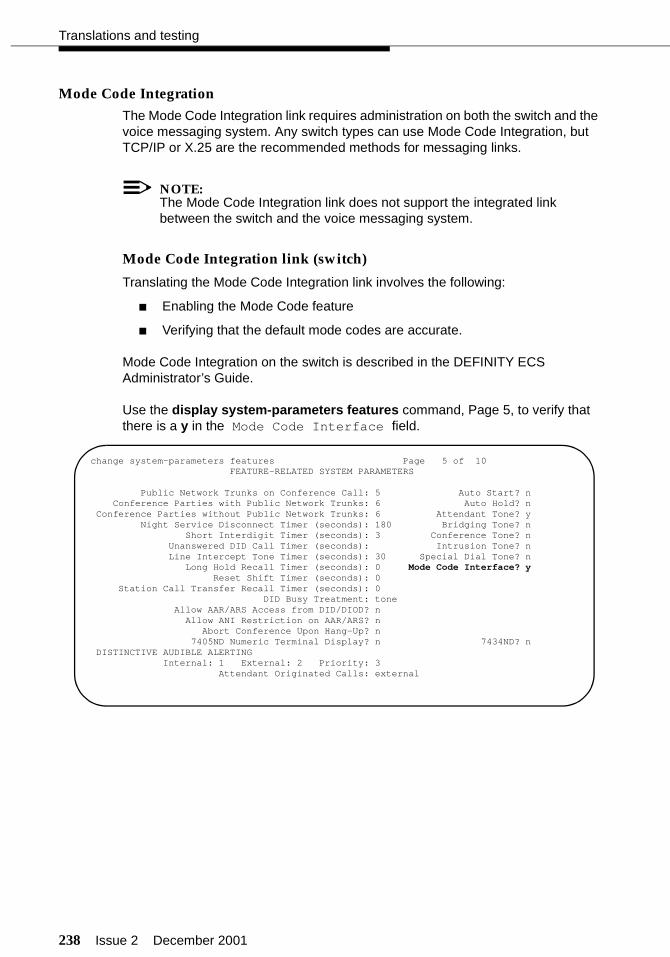
238 Issue 2 December 2001
Translations and testing
Mode Code Integration
The Mode Code Integration link requires administration on both the switch and the voice messaging system. Any switch types can use Mode Code Integration, but TCP/IP or X.25 are the recommended methods for messaging links.
NOTE:The Mode Code Integration link does not support the integrated link between the switch and the voice messaging system.
Mode Code Integration link (switch)
Translating the Mode Code Integration link involves the following:
■ Enabling the Mode Code feature
■ Verifying that the default mode codes are accurate.
Mode Code Integration on the switch is described in the DEFINITY ECS Administrator’s Guide.
Use the display system-parameters features command, Page 5, to verify that there is a y in the Mode Code Interface field.
change system-parameters features Page 5 of 10 FEATURE-RELATED SYSTEM PARAMETERS
Public Network Trunks on Conference Call: 5 Auto Start? n Conference Parties with Public Network Trunks: 6 Auto Hold? n Conference Parties without Public Network Trunks: 6 Attendant Tone? y Night Service Disconnect Timer (seconds): 180 Bridging Tone? n Short Interdigit Timer (seconds): 3 Conference Tone? n Unanswered DID Call Timer (seconds): Intrusion Tone? n Line Intercept Tone Timer (seconds): 30 Special Dial Tone? n Long Hold Recall Timer (seconds): 0 Mode Code Interface? y Reset Shift Timer (seconds): 0 Station Call Transfer Recall Timer (seconds): 0 DID Busy Treatment: tone Allow AAR/ARS Access from DID/DIOD? n Allow ANI Restriction on AAR/ARS? n Abort Conference Upon Hang-Up? n 7405ND Numeric Terminal Display? n 7434ND? n DISTINCTIVE AUDIBLE ALERTING Internal: 1 External: 2 Priority: 3 Attendant Originated Calls: external
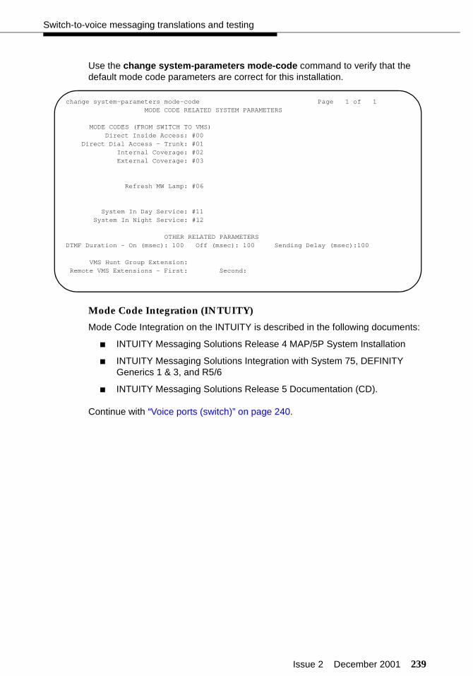
Issue 2 December 2001 239
Switch-to-voice messaging translations and testing
Use the change system-parameters mode-code command to verify that the default mode code parameters are correct for this installation.
Mode Code Integration (INTUITY)
Mode Code Integration on the INTUITY is described in the following documents:
■ INTUITY Messaging Solutions Release 4 MAP/5P System Installation
■ INTUITY Messaging Solutions Integration with System 75, DEFINITY Generics 1 & 3, and R5/6
■ INTUITY Messaging Solutions Release 5 Documentation (CD).
Continue with “Voice ports (switch)” on page 240.
change system-parameters mode-code Page 1 of 1MODE CODE RELATED SYSTEM PARAMETERS
MODE CODES (FROM SWITCH TO VMS)Direct Inside Access: #00
Direct Dial Access - Trunk: #01Internal Coverage: #02External Coverage: #03
Refresh MW Lamp: #06
System In Day Service: #11System In Night Service: #12
OTHER RELATED PARAMETERSDTMF Duration - On (msec): 100 Off (msec): 100 Sending Delay (msec):100
VMS Hunt Group Extension:Remote VMS Extensions - First: Second:

240 Issue 2 December 2001
Translations and testing
Voice ports (switch)
Use the add station command to administer the voice ports that are linked to the voice messaging system. On Page 1, assign the following fields as shown:
■ Extension — The extension must be in the dial plan but not assigned for any other purpose.
■ Type — Enter 2500 for the station type when using the TCP/IP or X.25 link. Enter VMI for the station type when using Mode Code integration.
■ Port — Each analog circuit pack supports 8, 16, or 24 analog voice connections. Depending on the circuit pack and the required number of voice ports, you may need to spread out the voice port assignments over more than one circuit pack. For example, if you are using a 16-port circuit pack, use no more than four ports of circuits 1-8 and four ports of circuits 9-16 on that circuit pack. If you still need more voice ports, select a circuit pack that is at least one-quarter carrier distance away from the first circuit pack. For example, if your system has 12 voice ports and you assign the first eight ports to the circuit pack in slot 3, assign the other four voice ports to a circuit pack in slot 7 or higher. See more about circuit pack characteristics in the DEFINITY ECS System Description.
■ Name — Assign the first port as VM1, and then increment the number for each subsequent port (VM2, VM3, and so on).
■ COR — Use the same COR for the voice ports that you use for the hunt groups. This COR should have the FRL set to 1 and should not allow access to trunk group CORs.
■ COS — Use a COS that allows data privacy.
add station 720 Page 1 of 3 STATION
Extension: 720 Lock Messages? n BCC: 0 Type: 2500 Security Code: TN: 1 Port: 01A0201 Coverage Path 1: COR: 35 Name: AUDIX1 Coverage Path 2: COS: 4
Hunt-to Station: Tests? n
STATION OPTIONSLoss Group: 1 Message Waiting Indicator: none
Off Premise Station? n
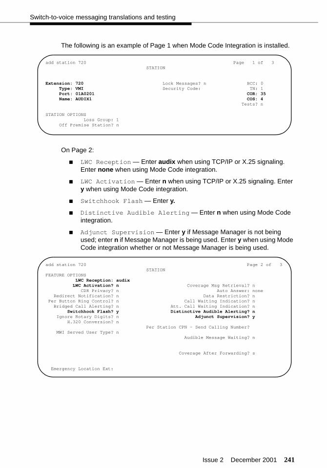
Issue 2 December 2001 241
Switch-to-voice messaging translations and testing
The following is an example of Page 1 when Mode Code Integration is installed.
On Page 2:
■ LWC Reception — Enter audix when using TCP/IP or X.25 signaling. Enter none when using Mode Code integration.
■ LWC Activation — Enter n when using TCP/IP or X.25 signaling. Enter y when using Mode Code integration.
■ Switchhook Flash — Enter y.
■ Distinctive Audible Alerting — Enter n when using Mode Code integration.
■ Adjunct Supervision — Enter y if Message Manager is not being used; enter n if Message Manager is being used. Enter y when using Mode Code integration whether or not Message Manager is being used.
add station 720 Page 1 of 3 STATION
Extension: 720 Lock Messages? n BCC: 0 Type: VMI Security Code: TN: 1 Port: 01A0201 COR: 35 Name: AUDIX1 COS: 4
Tests? n
STATION OPTIONSLoss Group: 1
Off Premise Station? n
add station 720 Page 2 of 3 STATIONFEATURE OPTIONS LWC Reception: audix LWC Activation? n Coverage Msg Retrieval? n CDR Privacy? n Auto Answer: none Redirect Notification? n Data Restriction? n Per Button Ring Control? n Call Waiting Indication? n Bridged Call Alerting? n Att. Call Waiting Indication? n
Switchhook Flash? y Distinctive Audible Alerting? nIgnore Rotary Digits? n Adjunct Supervision? y
H.320 Conversion? nPer Station CPN - Send Calling Number?
MWI Served User Type? nAudible Message Waiting? n
Coverage After Forwarding? s
Emergency Location Ext:
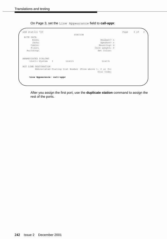
242 Issue 2 December 2001
Translations and testing
On Page 3, set the Line Appearance field to call-appr.
After you assign the first port, use the duplicate station command to assign the rest of the ports.
add station 720 Page 3 of 3 STATION SITE DATA Room: Headset? n Jack: Speaker? n Cable: Mounting: d Floor: Cord Length: 0 Building: Set Color:
ABBREVIATED DIALING List1: System 1 List2: List3:
HOT LINE DESTINATION Abbreviated Dialing List Number (From above 1, 2 or 3): Dial Code:
Line Appearance: call-appr
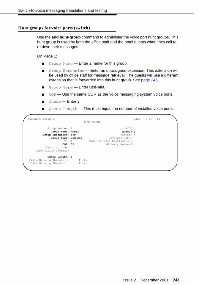
Issue 2 December 2001 243
Switch-to-voice messaging translations and testing
Hunt groups for voice ports (switch)
Use the add hunt-group command to administer the voice port hunt groups. This hunt group is used by both the office staff and the hotel guests when they call to retrieve their messages.
On Page 1:
■ Group Name — Enter a name for this group.
■ Group Extension — Enter an unassigned extension. This extension will be used by office staff for message retrieval. The guests will use a different extension that is forwarded into this hunt group. See page 245.
■ Group Type — Enter ucd-mia.
■ COR — Use the same COR as the voice messaging system voice ports.
■ Queue — Enter y.
■ Queue Length — This must equal the number of installed voice ports.
add hunt-group 1 Page 1 of 10 HUNT GROUP
Group Number: 1 ACD? nGroup Name: AUDIX Queue? y
Group Extension: 699 Vector? nGroup Type: ucd-mia Coverage Path:
TN: 1 Night Service Destination:COR: 35 MM Early Answer? n
Security Code: ISDN Caller Display:
Queue Length: 6Calls Warning Threshold: Port:Time Warning Threshold: Port:
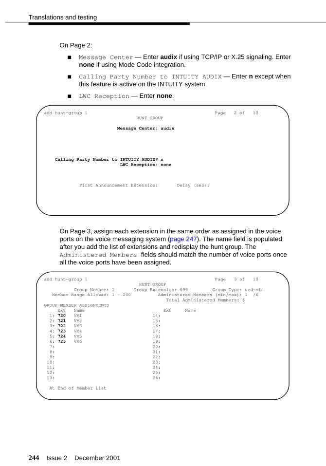
244 Issue 2 December 2001
Translations and testing
On Page 2:
■ Message Center — Enter audix if using TCP/IP or X.25 signaling. Enter none if using Mode Code integration.
■ Calling Party Number to INTUITY AUDIX — Enter n except when this feature is active on the INTUITY system.
■ LWC Reception — Enter none.
On Page 3, assign each extension in the same order as assigned in the voice ports on the voice messaging system (page 247). The name field is populated after you add the list of extensions and redisplay the hunt group. The Administered Members fields should match the number of voice ports once all the voice ports have been assigned.
add hunt-group 1 Page 2 of 10 HUNT GROUP
Message Center: audix
Calling Party Number to INTUITY AUDIX? n LWC Reception: none
First Announcement Extension: Delay (sec):
add hunt-group 1 Page 3 of 10 HUNT GROUP
Group Number: 1 Group Extension: 699 Group Type: ucd-mia Member Range Allowed: 1 - 200 Administered Members (min/max): 1 /6 Total Administered Members: 6GROUP MEMBER ASSIGNMENTS Ext Name Ext Name 1: 720 VM1 14: 2: 721 VM2 15: 3: 722 VM3 16: 4: 723 VM4 17: 5: 724 VM5 18: 6: 725 VM6 19: 7: 20: 8: 21: 9: 22: 10: 23: 11: 24: 12: 25: 13: 26:
At End of Member List

Issue 2 December 2001 245
Switch-to-voice messaging translations and testing
Extensions for guest message retrieval (switch)
The way guests retrieve their messages is to call an extension that is call forwarded to the voice messaging system hunt group extension. This is done using a standard station line that covers to the hunt group (defined on page 243). You can also assign an extension that allows guests to retrieve their messages when they are not in their room, and an extension that allows guests to leave messages for other guests without ringing the other guest’s room. See “Services to phone number mapping (INTUITY)” on page 249 for more information.
Use the add station command to add a station extension that is used only for accessing the voice messaging system voice messages:
■ Type — Enter 2500.
■ Port — Enter X (administration without hardware).
■ Name — Enter a name to identify this station.
■ COS — Enter a COS designated for voice messaging use.
add station 710 Page 1 of 3 STATION
Extension: 710 Lock Messages? n BCC: 0 Type: 2500 Security Code: TN: 1 Port: X Coverage Path 1: COR: 35 Name: GUEST VOICE MAIL Coverage Path 2: COS: 4
Hunt-to Station: Tests? y
STATION OPTIONSLoss Group: 1 Message Waiting Indicator:
Off Premise Station? n
add station 710 Page 2 of 3 STATIONFEATURE OPTIONS LWC Reception: audix LWC Activation? n Coverage Msg Retrieval? y
LWC Log External Calls? n Auto Answer: none CDR Privacy? n Data Restriction? n Redirect Notification? y Call Waiting Indication? n Per Button Ring Control? n Att. Call Waiting Indication? n Bridged Call Alerting? n Distinctive Audible Alerting? n
Switchhook Flash? y Adjunct Supervision? yIgnore Rotary Digits? n
H.320 Conversion? nPer Station CPN - Send Calling Number?
Audible Message Waiting? nMWI Served User Type? n
Coverage After Forwarding? s

246 Issue 2 December 2001
Translations and testing
On Page 3, set the Line Appearance field to call-appr.
After you assign the guest message retrieval extension, you must manually assign Call Forwarding to this extension so that calls will forward to the main voice messaging system hunt group extension. To use Call Forwarding, the Class of Service for this station (the guest message retrieval extension) must have Call Forwarding enabled (see page 115). In this example, you would forward calls intended for extension 710 to extension 699. You can set up Call Forwarding from any telephone that has console permissions.
Call Coverage path (switch)
Use the add coverage path command to define the coverage path that redirects unanswered calls to the voice messaging system (as defined on page 243). After three rings, calls go to hunt group 1 (h1). If the voice messaging system is down or the voice ports are all busy, then the calls forward to the attendant (attd).
add station 710 Page 3 of 3 STATION SITE DATA Room: 710 Headset? n Jack: Speaker? n Cable: Mounting: d Floor: Cord Length: 0 Building: Set Color:
ABBREVIATED DIALING List1: System 1 List2: List3:
HOT LINE DESTINATION Abbreviated Dialing List Number (From above 1, 2 or 3): Dial Code:
Line Appearance: call-appr
add coverage path 1 COVERAGE PATH
Coverage Path Number: 1Hunt after Coverage? n
Next Path Number: Linkage
COVERAGE CRITERIA Station/Group Status Inside Call Outside Call Active? y y Busy? y y Don’t Answer? y y Number of Rings: 3 All? n n DND/SAC/Goto Cover? y y
COVERAGE POINTS
Terminate to Coverage Pts. with Bridged Appearances? n
Point1: h1 Point2: attd Point3:Point4: Point5: Point6:

Issue 2 December 2001 247
Switch-to-voice messaging translations and testing
INTUITY AUDIX voice ports (INTUITY)
To assign the voice port extension numbers to each activated voice channel on the INTUITY system:
NOTE:Port numbers and channel numbers start with 0 (zero).
1. Enter the Voice System Administration > Voice Equipment command.
2. Press to display the actions menu.
3. Select the Assign/Change option.
4. Select the PBX Extension to Channel option.
5. Enter a voice port extension number and a channel number (0-5). Use the same order here as was used when the hunt group extensions were assigned (page 243).
6. Press to save the assignment. A message displays confirming that the extension was mapped to a channel.
7. Press Enter to acknowledge the message.
8. Repeat this procedure for each voice port extension.
9. When finished, press to exit. You must now map services to channels for normal operation.
10. Select the Services to Channels option.
11. Enter the numbers of the channels the customer has purchased in the Channel Numbers field. For example, if the customer purchased 12 channels, enter 0-11.
12. Enter *DNIS_SVC for all channels in the Service Name field.
F8
+--------------------------------------------++ Assign PBX Extension to a Channel ++--------------------------------------------+| PBX Extension: || Channel Number: || |+--------------------------------------------+
F3
F6
+--------------------------------------------++ Assign Services to Channels ++--------------------------------------------+| Channel Numbers: || Service Name: || |+--------------------------------------------+

248 Issue 2 December 2001
Translations and testing
13. Press to save the assignment.
An acknowledgement message is displayed. Press to continue.
14. Press repeatedly to return to the INTUITY Main Menu.
15. Enter the Voice System Administration > Voice Equipment command to display the voice channel setup.
The channel state should normally be Inserv (in-service), but it could be foos (facility out-of-service) or manoos (manually out-of-service). The SERVICE NAME should be *DNIS_SVC, and the GROUP should be set to 2.
F3
F1
F6
+------------------------------------------------------------------------------++ Display Voice Equipment ++------------------------------------------------------------------------------+| CD.PT CHN STATE STATE-CHNG-TIME SERVICE-NAME PHONE GROUP OPTS TYPE || || CARD 0 STATE: Inserv CLASS: Analog(TR) O.S. INDEX: 0 || NAME: AYC10 OPTIONS: master 1,no tdm,tt || FUNCTION: TipRing || || 0.0 0 Inserv Mar 20 18:49:25 *DNIS_SVC 720 2 talk IVC6 || 0.1 1 Inserv Mar 20 18:49:25 *DNIS_SVC 721 2 talk IVC6 || 0.2 2 Inserv Mar 20 18:49:25 *DNIS_SVC 722 2 talk IVC6 || 0.3 3 Inserv Mar 20 18:49:25 *DNIS_SVC 723 2 talk IVC6 || 0.4 4 Inserv Mar 20 18:49:25 *DNIS_SVC 724 2 talk IVC6 || 0.5 5 Inserv Mar 20 18:49:25 *DNIS_SVC 725 2 talk IVC6 |+------------------------------------------------------------------------------+

Issue 2 December 2001 249
Switch-to-voice messaging translations and testing
Services to phone number mapping (INTUITY)
You must map the extension numbers used to retrieve and leave voice mail messages to the services the extensions provide. These assignments control how the call is processed by the INTUITY system. In the examples as shown in this section, extension 699 is used by the office staff; extension 710 is used by the guests from their guest rooms; and extension 770 is used for printing fax messages.
! CAUTION:If the AUDIX service is not assigned, calls placed to the office staff exten-sions will hear an “Extension not valid” message when the call is transferred to INTUITY AUDIX, and the caller cannot leave a message.
Use the Voice System Administration > Number Services > Assign Service command to access the number service screen.
Assign Called Numbers and Calling Numbers to the following services:
■ AUDIX — Enter the extension that the office staff call to retrieve their AUDIX messages. In the example for this book, that would be extension 699.
■ AUDIX+ldg — Enter any.
■ lodging — Enter the extension that guests call to retrieve their lodging messages. In the example for this book, that would be extension 710.
■ ldg_ni_vm — Enter an extension that guests can call to retrieve their messages when away from their room. This extension should be assigned to a DID number so guests can retrieve their messages when outside of the hotel. This option is not available on all systems.
■ ldg_ni_ca — Enter an extension that guests can call to leave a message for another guest without ringing the other guest’s room. This extension must have a coverage path that redirects to the voice mail extension and should be call forwarded to the voice mail extension (in this example, extension 699). This option is not available on all systems.
■ LGfax — Enter the extension callers would use to transmit a fax. In the example for this book, that would be extension 770.
The Calling Numbers fields will always be any. The example shown here matches the extension used elsewhere in this book.
+-----------------------------------------------------------++ Assign Number Service ++-----------------------------------------------------------+| Called Numbers:699 to 699 || Calling Numbers:any to any || Service Name:AUDIX |+-----------------------------------------------------------+

250 Issue 2 December 2001
Translations and testing
Attendant and administrator passwords (INTUITY)
Use the Lodging Administration > Lodging Administrator Registration command to access the administrator registration screen. Using this screen, you must assign an administrator extension (an unused extension on the switch), an administrator password, and an attendant password. These passwords can be used to retrieve voice messages for the guests. Your administration should look similar to this screen.
! CAUTION:When creating passwords, do not use a sequential string of digits (such as 1234) or a repeated digit (such as 5555).
+----------------------------------++Lodging Administrator Registration++----------------------------------+|Administrator Extension: 475 || Administrator Password: 3872 || Attendant Password: 6391 |+----------------------------------+
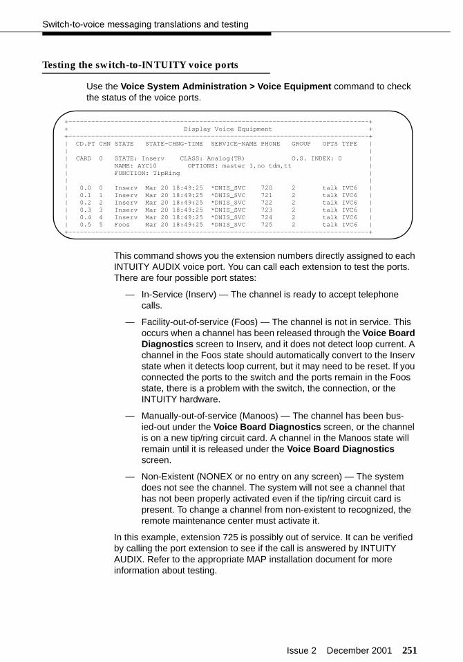
Issue 2 December 2001 251
Switch-to-voice messaging translations and testing
Testing the switch-to-INTUITY voice ports
Use the Voice System Administration > Voice Equipment command to check the status of the voice ports.
This command shows you the extension numbers directly assigned to each INTUITY AUDIX voice port. You can call each extension to test the ports. There are four possible port states:
— In-Service (Inserv) — The channel is ready to accept telephone calls.
— Facility-out-of-service (Foos) — The channel is not in service. This occurs when a channel has been released through the Voice Board Diagnostics screen to Inserv, and it does not detect loop current. A channel in the Foos state should automatically convert to the Inserv state when it detects loop current, but it may need to be reset. If you connected the ports to the switch and the ports remain in the Foos state, there is a problem with the switch, the connection, or the INTUITY hardware.
— Manually-out-of-service (Manoos) — The channel has been bus-ied-out under the Voice Board Diagnostics screen, or the channel is on a new tip/ring circuit card. A channel in the Manoos state will remain until it is released under the Voice Board Diagnostics screen.
— Non-Existent (NONEX or no entry on any screen) — The system does not see the channel. The system will not see a channel that has not been properly activated even if the tip/ring circuit card is present. To change a channel from non-existent to recognized, the remote maintenance center must activate it.
In this example, extension 725 is possibly out of service. It can be verified by calling the port extension to see if the call is answered by INTUITY AUDIX. Refer to the appropriate MAP installation document for more information about testing.
+------------------------------------------------------------------------------++ Display Voice Equipment ++------------------------------------------------------------------------------+| CD.PT CHN STATE STATE-CHNG-TIME SERVICE-NAME PHONE GROUP OPTS TYPE || || CARD 0 STATE: Inserv CLASS: Analog(TR) O.S. INDEX: 0 || NAME: AYC10 OPTIONS: master 1,no tdm,tt || FUNCTION: TipRing || || 0.0 0 Inserv Mar 20 18:49:25 *DNIS_SVC 720 2 talk IVC6 || 0.1 1 Inserv Mar 20 18:49:25 *DNIS_SVC 721 2 talk IVC6 || 0.2 2 Inserv Mar 20 18:49:25 *DNIS_SVC 722 2 talk IVC6 || 0.3 3 Inserv Mar 20 18:49:25 *DNIS_SVC 723 2 talk IVC6 || 0.4 4 Inserv Mar 20 18:49:25 *DNIS_SVC 724 2 talk IVC6 || 0.5 5 Foos Mar 20 18:49:25 *DNIS_SVC 725 2 talk IVC6 |+------------------------------------------------------------------------------+
252 Issue 2 December 2001
Translations and testing
Voice messaging-to-PMS translations and testing
There are two ways that the voice messaging system lodging software and the PMS software can exchange messages for database updates:
■ Use the Switch/INTUITY/PMS Link Integration feature. This feature uses the switch to exchange the voice mail database update messages between the voice messaging system and the PMS. This option is known as the “PMS Interface for GuestWorks.” The INTUITY system currently defaults to this option. This option can be used with TCP/IP or X.25 links, but cannot be used for Mode Code Integration.
Use this integration method whenever connecting over C-LAN to a voice messaging system that supports lodging software, such as INTUITY Lodging or the InnLine 2020.
■ Use a hard-wired link between the MAP and the PMS voice messaging port. This link is illustrated in Figure 12 on page 40. This option is known as the “Stand-alone Mode.” This option can be used with TCP/IP or X.25 links, and must be used for Mode Code Integration. This link should also be used if the PMS must keep track of the number of voice mail messages for each guest.
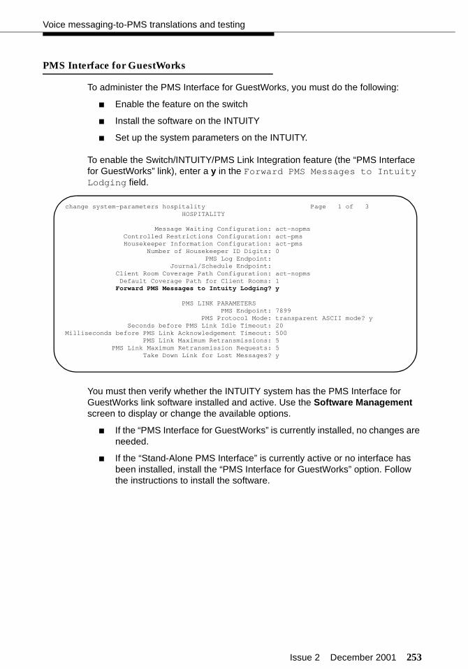
Issue 2 December 2001 253
Voice messaging-to-PMS translations and testing
PMS Interface for GuestWorks
To administer the PMS Interface for GuestWorks, you must do the following:
■ Enable the feature on the switch
■ Install the software on the INTUITY
■ Set up the system parameters on the INTUITY.
To enable the Switch/INTUITY/PMS Link Integration feature (the “PMS Interface for GuestWorks” link), enter a y in the Forward PMS Messages to Intuity Lodging field.
You must then verify whether the INTUITY system has the PMS Interface for GuestWorks link software installed and active. Use the Software Management screen to display or change the available options.
■ If the “PMS Interface for GuestWorks” is currently installed, no changes are needed.
■ If the “Stand-Alone PMS Interface” is currently active or no interface has been installed, install the “PMS Interface for GuestWorks” option. Follow the instructions to install the software.
change system-parameters hospitality Page 1 of 3 HOSPITALITY
Message Waiting Configuration: act-nopms Controlled Restrictions Configuration: act-pms Housekeeper Information Configuration: act-pms Number of Housekeeper ID Digits: 0 PMS Log Endpoint: Journal/Schedule Endpoint: Client Room Coverage Path Configuration: act-nopms Default Coverage Path for Client Rooms: 1
Forward PMS Messages to Intuity Lodging? y
PMS LINK PARAMETERS PMS Endpoint: 7899 PMS Protocol Mode: transparent ASCII mode? y
Seconds before PMS Link Idle Timeout: 20Milliseconds before PMS Link Acknowledgement Timeout: 500 PMS Link Maximum Retransmissions: 5 PMS Link Maximum Retransmission Requests: 5 Take Down Link for Lost Messages? y

254 Issue 2 December 2001
Translations and testing
Once the software is installed, use the Lodging Administration > System Parameter Administration command to administer the system parameters for INTUITY Lodging.
■ Attendant Extensions — Enter 0 for the attendant console, the backup telephone extensions, and any extensions that will be used to retrieve messages for guests.
■ Primary Attendant — Enter the attendant console dial-up number (usually 0) or extension.
■ Default Language — Select a default language option.
+--------------------------------------------------------------------------++ System Parameter Administration ++--------------------------------------------------------------------------+| Attendant Extensions: || 2000 195 0 || Hunt Group Or || Primary Attendant: 0 || || Voice Mail Parameters || Mailbox Size: 6 min Mailbox Type: Separate || Pause For TT Input: 4 sec Play Back Format: FIFO || Maximum Extension Length: 4 || Maximum Message Length: 120 sec ||Allow Guests To Save Messages?: Yes ||Lamp ON For New Messages Only?: Yes || Automatic Transfer to || Operator At End Of Call?: No || Default Language: American English |+--------------------------------------------------------------------------+
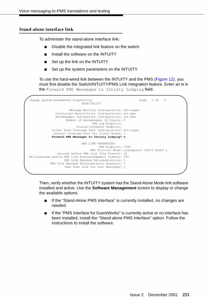
Issue 2 December 2001 255
Voice messaging-to-PMS translations and testing
Stand-alone interface link
To administer the stand-alone interface link:
■ Disable the integrated link feature on the switch
■ Install the software on the INTUITY
■ Set up the link on the INTUITY
■ Set up the system parameters on the INTUITY.
To use the hard-wired link between the INTUITY and the PMS (Figure 12), you must first disable the Switch/INTUITY/PMS Link Integration feature. Enter an n in the Forward PMS Messages to Intuity Lodging field.
Then, verify whether the INTUITY system has the Stand-Alone Mode link software installed and active. Use the Software Management screen to display or change the available options.
■ If the “Stand-Alone PMS Interface” is currently installed, no changes are needed.
■ If the “PMS Interface for GuestWorks” is currently active or no interface has been installed, install the “Stand-alone PMS Interface” option. Follow the instructions to install the software.
change system-parameters hospitality Page 1 of 3 HOSPITALITY
Message Waiting Configuration: act-nopms Controlled Restrictions Configuration: act-pms Housekeeper Information Configuration: act-pms Number of Housekeeper ID Digits: 0 PMS Log Endpoint: Journal/Schedule Endpoint: Client Room Coverage Path Configuration: act-nopms Default Coverage Path for Client Rooms: 1
Forward PMS Messages to Intuity Lodging? n
PMS LINK PARAMETERS PMS Endpoint: 7899 PMS Protocol Mode: transparent ASCII mode? y
Seconds before PMS Link Idle Timeout: 20Milliseconds before PMS Link Acknowledgement Timeout: 500 PMS Link Maximum Retransmissions: 5 PMS Link Maximum Retransmission Requests: 5 Take Down Link for Lost Messages? y
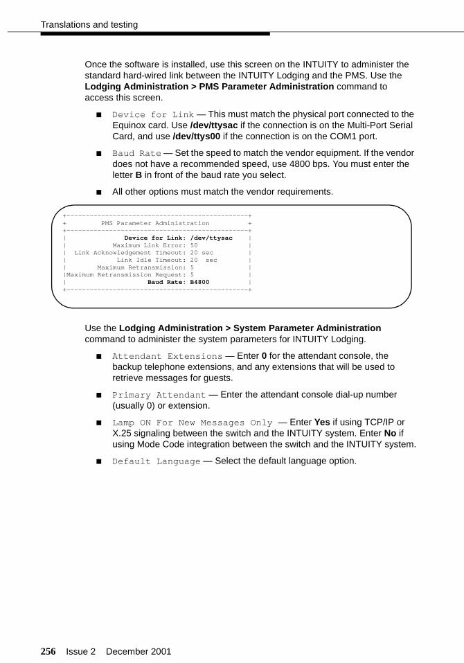
256 Issue 2 December 2001
Translations and testing
Once the software is installed, use this screen on the INTUITY to administer the standard hard-wired link between the INTUITY Lodging and the PMS. Use the Lodging Administration > PMS Parameter Administration command to access this screen.
■ Device for Link — This must match the physical port connected to the Equinox card. Use /dev/ttysac if the connection is on the Multi-Port Serial Card, and use /dev/ttys00 if the connection is on the COM1 port.
■ Baud Rate — Set the speed to match the vendor equipment. If the vendor does not have a recommended speed, use 4800 bps. You must enter the letter B in front of the baud rate you select.
■ All other options must match the vendor requirements.
Use the Lodging Administration > System Parameter Administration command to administer the system parameters for INTUITY Lodging.
■ Attendant Extensions — Enter 0 for the attendant console, the backup telephone extensions, and any extensions that will be used to retrieve messages for guests.
■ Primary Attendant — Enter the attendant console dial-up number (usually 0) or extension.
■ Lamp ON For New Messages Only — Enter Yes if using TCP/IP or X.25 signaling between the switch and the INTUITY system. Enter No if using Mode Code integration between the switch and the INTUITY system.
■ Default Language — Select the default language option.
+-----------------------------------------------++ PMS Parameter Administration ++-----------------------------------------------+| Device for Link: /dev/ttysac || Maximum Link Error: 50 || Link Acknowledgement Timeout: 20 sec || Link Idle Timeout: 20 sec || Maximum Retransmission: 5 ||Maximum Retransmission Request: 5 || Baud Rate: B4800 |+-----------------------------------------------+
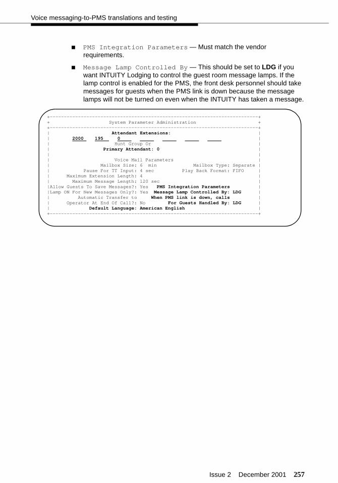
Issue 2 December 2001 257
Voice messaging-to-PMS translations and testing
■ PMS Integration Parameters — Must match the vendor requirements.
■ Message Lamp Controlled By — This should be set to LDG if you want INTUITY Lodging to control the guest room message lamps. If the lamp control is enabled for the PMS, the front desk personnel should take messages for guests when the PMS link is down because the message lamps will not be turned on even when the INTUITY has taken a message.
+--------------------------------------------------------------------------++ System Parameter Administration ++--------------------------------------------------------------------------+| Attendant Extensions: || 2000 195 0 || Hunt Group Or || Primary Attendant: 0 || || Voice Mail Parameters || Mailbox Size: 6 min Mailbox Type: Separate || Pause For TT Input: 4 sec Play Back Format: FIFO || Maximum Extension Length: 4 || Maximum Message Length: 120 sec ||Allow Guests To Save Messages?: Yes PMS Integration Parameters ||Lamp ON For New Messages Only?: Yes Message Lamp Controlled By: LDG || Automatic Transfer to When PMS link is down, calls || Operator At End Of Call?: No For Guests Handled By: LDG || Default Language: American English |+--------------------------------------------------------------------------+

258 Issue 2 December 2001
Translations and testing
Testing the INTUITY Lodging-to-PMS link
After the connection is complete, and the link is active, the mini-tester should show the following results (see the Note on page 5). The leads marked with an asterisk are controlled by the INTUITY system, and the PMS controls the other leads.
! CAUTION:After using a mini-tester to check data leads, you MUST remove the mini-tester from the connection. DO NOT leave the mini-tester in-line during actual operation.
After the connection is complete and the INTUITY link is active, the following may indicate that the PMS is not active. Check with the vendor to verify whether the link is active.
TD*
RTS*
DTR*
RD
CTSDSR
CD
green
green
red
green
red
dark
green
TD*
RTS*
DTR*
RD
CTSDSR
CD
red
red
red
red
red
dark
green
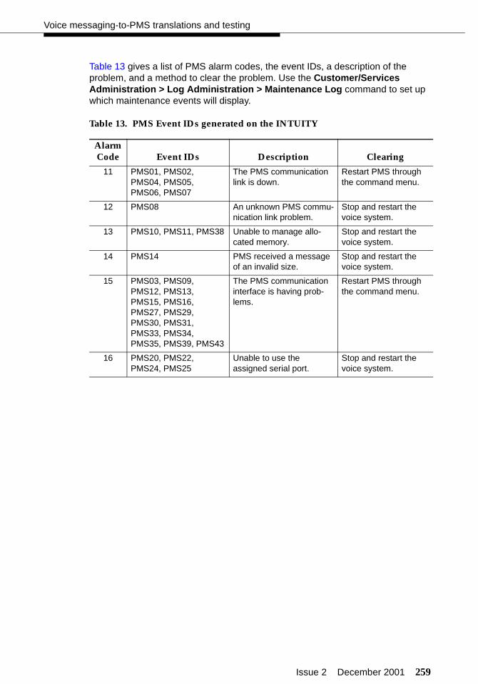
Issue 2 December 2001 259
Voice messaging-to-PMS translations and testing
Table 13 gives a list of PMS alarm codes, the event IDs, a description of the problem, and a method to clear the problem. Use the Customer/Services Administration > Log Administration > Maintenance Log command to set up which maintenance events will display.
Table 13. PMS Event IDs generated on the INTUITY
Alarm Code Event IDs Description Clearing
11 PMS01, PMS02, PMS04, PMS05, PMS06, PMS07
The PMS communication link is down.
Restart PMS through the command menu.
12 PMS08 An unknown PMS commu-nication link problem.
Stop and restart the voice system.
13 PMS10, PMS11, PMS38 Unable to manage allo-cated memory.
Stop and restart the voice system.
14 PMS14 PMS received a message of an invalid size.
Stop and restart the voice system.
15 PMS03, PMS09, PMS12, PMS13, PMS15, PMS16, PMS27, PMS29, PMS30, PMS31, PMS33, PMS34, PMS35, PMS39, PMS43
The PMS communication interface is having prob-lems.
Restart PMS through the command menu.
16 PMS20, PMS22, PMS24, PMS25
Unable to use the assigned serial port.
Stop and restart the voice system.
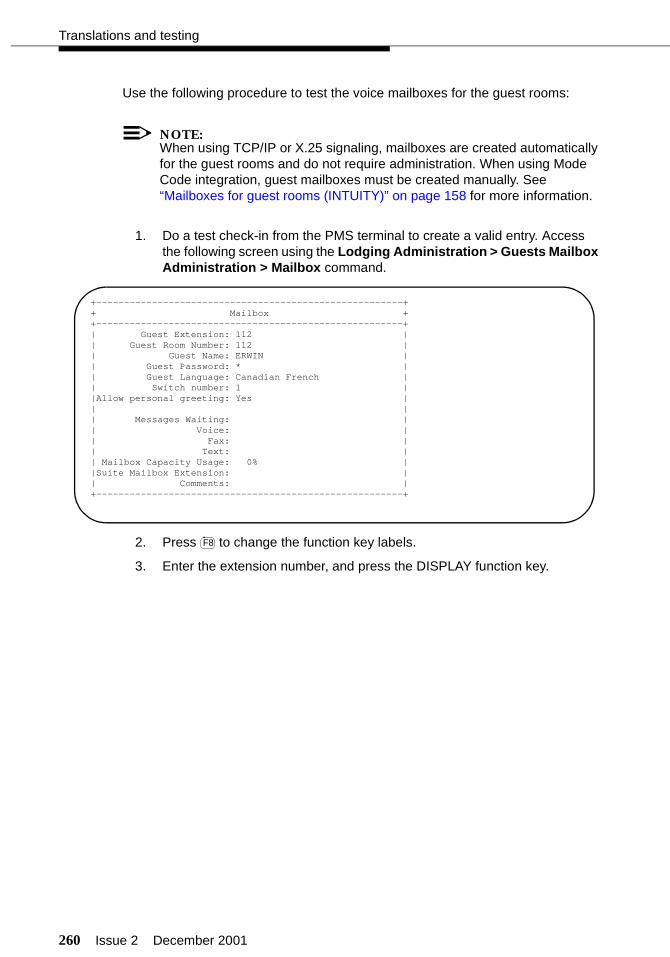
260 Issue 2 December 2001
Translations and testing
Use the following procedure to test the voice mailboxes for the guest rooms:
NOTE:When using TCP/IP or X.25 signaling, mailboxes are created automatically for the guest rooms and do not require administration. When using Mode Code integration, guest mailboxes must be created manually. See “Mailboxes for guest rooms (INTUITY)” on page 158 for more information.
1. Do a test check-in from the PMS terminal to create a valid entry. Access the following screen using the Lodging Administration > Guests Mailbox Administration > Mailbox command.
2. Press to change the function key labels.
3. Enter the extension number, and press the DISPLAY function key.
+-------------------------------------------------------++ Mailbox ++-------------------------------------------------------+| Guest Extension: 112 || Guest Room Number: 112 || Guest Name: ERWIN || Guest Password: * || Guest Language: Canadian French || Switch number: 1 ||Allow personal greeting: Yes || || Messages Waiting: || Voice: || Fax: || Text: || Mailbox Capacity Usage: 0% ||Suite Mailbox Extension: || Comments: |+-------------------------------------------------------+
F8
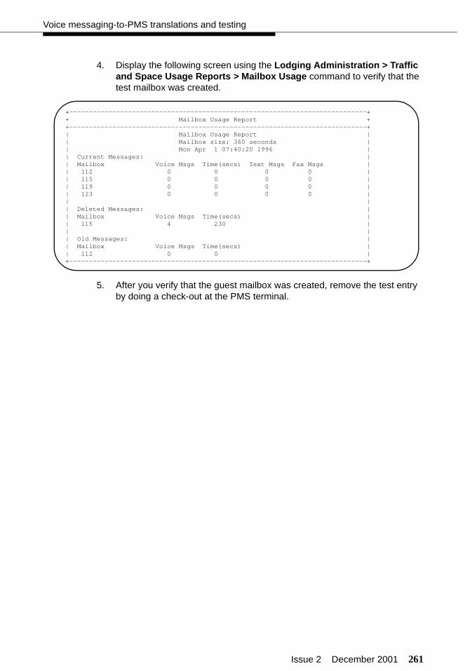
Issue 2 December 2001 261
Voice messaging-to-PMS translations and testing
4. Display the following screen using the Lodging Administration > Traffic and Space Usage Reports > Mailbox Usage command to verify that the test mailbox was created.
5. After you verify that the guest mailbox was created, remove the test entry by doing a check-out at the PMS terminal.
+----------------------------------------------------------------------------++ Mailbox Usage Report ++----------------------------------------------------------------------------+| Mailbox Usage Report || Mailbox size: 360 seconds || Mon Apr 1 07:40:20 1996 || Current Messages: || Mailbox Voice Msgs Time(secs) Text Msgs Fax Msgs || 112 0 0 0 0 || 115 0 0 0 0 || 119 0 0 0 0 || 123 0 0 0 0 || || Deleted Messages: || Mailbox Voice Msgs Time(secs) || 115 4 230 || || Old Messages: || Mailbox Voice Msgs Time(secs) || 112 0 0 |+----------------------------------------------------------------------------+

262 Issue 2 December 2001
Translations and testing
Switch-to-call accounting translations and testing
You must assign the link between the switch and the INTUITY, administer the CDR parameters, and enable CDR for each incoming and outgoing trunk group that the customer wishes to record. If a stand-alone call accounting system (such as Xiox) is used, the vendor must assist in setting up the call accounting system.
Link parameters (INTUITY)
The data link between the switch and the INTUITY Lodging Call Accounting must be administered by the Homisco technician when he or she installs the software on the INTUITY platform.
CDR parameters (switch)
Use the change system-parameters cdr command to assign the CDR parameters on the switch.
■ Primary Output Format — Enter printer (or the format required by the call accounting vendor).
■ Primary Output Endpoint — Do one of the following:
— Enter CDR1 if the call accounting system is connecting to the switch over a terminal server. You must also administer the IP Services form for the CDR interface.
— Enter eia if the call accounting system is directly connected to the switch using the DCE port.
— Enter the data module extension if using a switched connection. A data module must be administered first before making this assign-ment.
■ Secondary Output Format — Enter printer (or the format required by the call accounting vendor). The secondary output port is not always used.
■ Secondary Output Endpoint — Do one of the following (if the secondary output port is used):
— Enter CDR2 if the call accounting system is connecting to the switch over a terminal server. You must also administer the IP Services form for the CDR interface.
— Enter eia if the call accounting system is directly connected to the switch using the DCE port.
— Enter the data module extension if using a switched connection. A data module must be administered first before making this assign-ment.
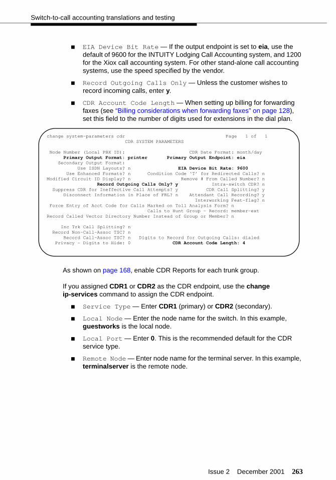
Issue 2 December 2001 263
Switch-to-call accounting translations and testing
■ EIA Device Bit Rate — If the output endpoint is set to eia, use the default of 9600 for the INTUITY Lodging Call Accounting system, and 1200 for the Xiox call accounting system. For other stand-alone call accounting systems, use the speed specified by the vendor.
■ Record Outgoing Calls Only — Unless the customer wishes to record incoming calls, enter y.
■ CDR Account Code Length — When setting up billing for forwarding faxes (see “Billing considerations when forwarding faxes” on page 128), set this field to the number of digits used for extensions in the dial plan.
As shown on page 168, enable CDR Reports for each trunk group.
If you assigned CDR1 or CDR2 as the CDR endpoint, use the change ip-services command to assign the CDR endpoint.
■ Service Type — Enter CDR1 (primary) or CDR2 (secondary).
■ Local Node — Enter the node name for the switch. In this example, guestworks is the local node.
■ Local Port — Enter 0. This is the recommended default for the CDR service type.
■ Remote Node — Enter node name for the terminal server. In this example, terminalserver is the remote node.
change system-parameters cdr Page 1 of 1 CDR SYSTEM PARAMETERS
Node Number (Local PBX ID): CDR Date Format: month/day Primary Output Format: printer Primary Output Endpoint: eia Secondary Output Format: Use ISDN Layouts? n EIA Device Bit Rate: 9600 Use Enhanced Formats? n Condition Code ‘T’ for Redirected Calls? nModified Circuit ID Display? n Remove # From Called Number? n Record Outgoing Calls Only? y Intra-switch CDR? n Suppress CDR for Ineffective Call Attempts? y CDR Call Splitting? y Disconnect Information in Place of FRL? n Attendant Call Recording? y Interworking Feat-flag? n Force Entry of Acct Code for Calls Marked on Toll Analysis Form? n Calls to Hunt Group - Record: member-extRecord Called Vector Directory Number Instead of Group or Member? n
Inc Trk Call Splitting? n Record Non-Call-Assoc TSC? n Record Call-Assoc TSC? n Digits to Record for Outgoing Calls: dialed Privacy - Digits to Hide: 0 CDR Account Code Length: 4
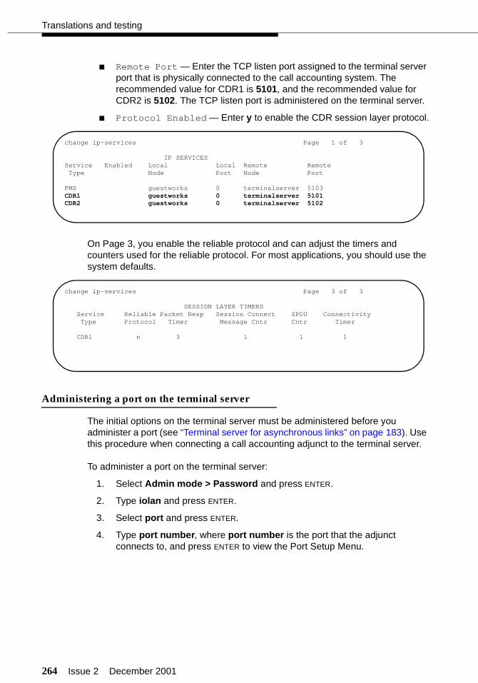
264 Issue 2 December 2001
Translations and testing
■ Remote Port — Enter the TCP listen port assigned to the terminal server port that is physically connected to the call accounting system. The recommended value for CDR1 is 5101, and the recommended value for CDR2 is 5102. The TCP listen port is administered on the terminal server.
■ Protocol Enabled — Enter y to enable the CDR session layer protocol.
On Page 3, you enable the reliable protocol and can adjust the timers and counters used for the reliable protocol. For most applications, you should use the system defaults.
Administering a port on the terminal server
The initial options on the terminal server must be administered before you administer a port (see “Terminal server for asynchronous links” on page 183). Use this procedure when connecting a call accounting adjunct to the terminal server.
To administer a port on the terminal server:
1. Select Admin mode > Password and press ENTER.
2. Type iolan and press ENTER.
3. Select port and press ENTER.
4. Type port number, where port number is the port that the adjunct connects to, and press ENTER to view the Port Setup Menu.
change ip-services Page 1 of 3
IP SERVICESService Enabled Local Local Remote RemoteType Node Port Node Port
PMS guestworks 0 terminalserver 5103CDR1 guestworks 0 terminalserver 5101CDR2 guestworks 0 terminalserver 5102
change ip-services Page 3 of 3
SESSION LAYER TIMERSService Reliable Packet Resp Session Connect SPDU ConnectivityType Protocol Timer Message Cntr Cntr Timer
CDR1 n 3 1 1 1
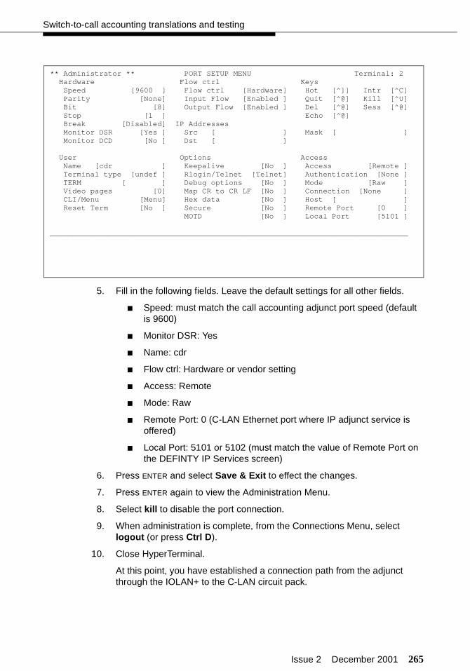
Issue 2 December 2001 265
Switch-to-call accounting translations and testing
5. Fill in the following fields. Leave the default settings for all other fields.
■ Speed: must match the call accounting adjunct port speed (default is 9600)
■ Monitor DSR: Yes
■ Name: cdr
■ Flow ctrl: Hardware or vendor setting
■ Access: Remote
■ Mode: Raw
■ Remote Port: 0 (C-LAN Ethernet port where IP adjunct service is offered)
■ Local Port: 5101 or 5102 (must match the value of Remote Port on the DEFINTY IP Services screen)
6. Press ENTER and select Save & Exit to effect the changes.
7. Press ENTER again to view the Administration Menu.
8. Select kill to disable the port connection.
9. When administration is complete, from the Connections Menu, select logout (or press Ctrl D).
10. Close HyperTerminal.
At this point, you have established a connection path from the adjunct through the IOLAN+ to the C-LAN circuit pack.
** Administrator ** PORT SETUP MENU Terminal: 2 Hardware Flow ctrl Keys Speed [9600 ] Flow ctrl [Hardware] Hot [^]] Intr [^C] Parity [None] Input Flow [Enabled ] Quit [^@] Kill [^U] Bit [8] Output Flow [Enabled ] Del [^@] Sess [^@] Stop [1 ] Echo [^@] Break [Disabled] IP Addresses Monitor DSR [Yes ] Src [ ] Mask [ ] Monitor DCD [No ] Dst [ ]
User Options Access Name [cdr ] Keepalive [No ] Access [Remote ] Terminal type [undef ] Rlogin/Telnet [Telnet] Authentication [None ] TERM [ ] Debug options [No ] Mode [Raw ] Video pages [0] Map CR to CR LF [No ] Connection [None ] CLI/Menu [Menu] Hex data [No ] Host [ ] Reset Term [No ] Secure [No ] Remote Port [0 ] MOTD [No ] Local Port [5101 ]
________________________________________________________________________________
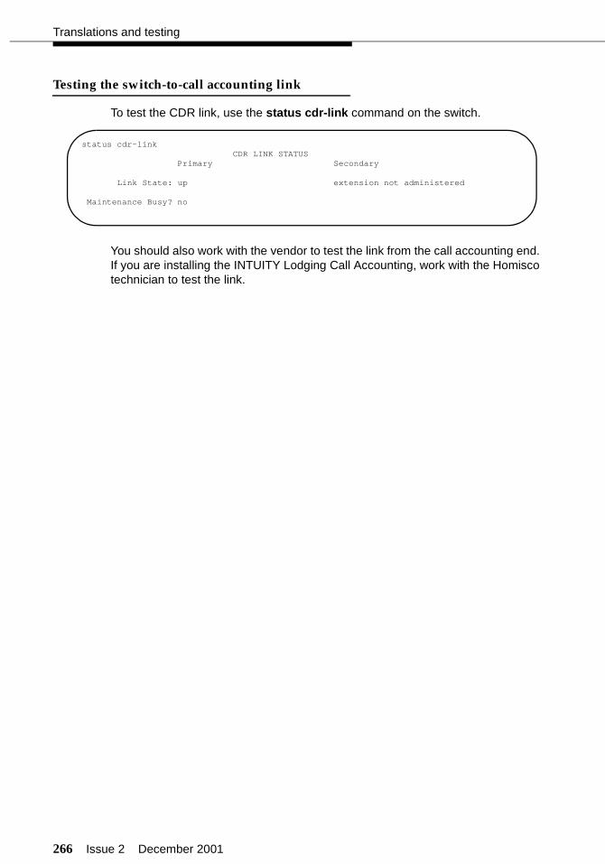
266 Issue 2 December 2001
Translations and testing
Testing the switch-to-call accounting link
To test the CDR link, use the status cdr-link command on the switch.
You should also work with the vendor to test the link from the call accounting end. If you are installing the INTUITY Lodging Call Accounting, work with the Homisco technician to test the link.
status cdr-linkCDR LINK STATUS
Primary Secondary
Link State: up extension not administered
Maintenance Busy? no

Issue 2 December 2001 267
INTUITY Lodging Call Accounting-to-PMS translations
INTUITY Lodging Call Accounting-to-PMStranslations and testing
The data link between the INTUITY Lodging Call Accounting and the PMS must be administered by the Homisco technician when he or she installs the software on the INTUITY platform.
If a stand-alone call accounting system (such as Xiox) is used, the vendor must assist in setting up the call accounting system.
To test the call accounting link, make a test call from a test guest room to verify that the call is posted on the call accounting system and the PMS.
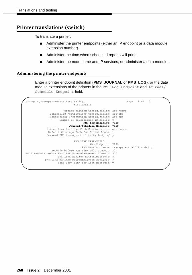
268 Issue 2 December 2001
Translations and testing
Printer translations (switch)
To translate a printer:
■ Administer the printer endpoints (either an IP endpoint or a data module extension number).
■ Administer the time when scheduled reports will print.
■ Administer the node name and IP services, or administer a data module.
Administering the printer endpoints
Enter a printer endpoint definition (PMS_JOURNAL or PMS_LOG), or the data module extensions of the printers in the PMS Log Endpoint and Journal/Schedule Endpoint field.
change system-parameters hospitality Page 1 of 3 HOSPITALITY
Message Waiting Configuration: act-nopms Controlled Restrictions Configuration: act-pms Housekeeper Information Configuration: act-pms Number of Housekeeper ID Digits: 0
PMS Log Endpoint: 7850 Journal/Schedule Endpoint: 7850 Client Room Coverage Path Configuration: act-nopms Default Coverage Path for Client Rooms: 1
Forward PMS Messages to Intuity Lodging? y
PMS LINK PARAMETERS PMS Endpoint: 7899 PMS Protocol Mode: transparent ASCII mode? y
Seconds before PMS Link Idle Timeout: 20Milliseconds before PMS Link Acknowledgement Timeout: 500 PMS Link Maximum Retransmissions: 5 PMS Link Maximum Retransmission Requests: 5 Take Down Link for Lost Messages? y

Issue 2 December 2001 269
Printer translations (switch)
For a system printer, enter a printer endpoint definition (SYS_PRNT), or enter the data module extension in the System Printer Endpoint field. If you are connecting the system printer to the DCE EIA port (instead of using that port for call accounting), enter eia in this field.
change system-parameters features Page 4 of 10FEATURE-RELATED SYSTEM PARAMETERS
SYSTEM PRINTER PARAMETERSSystem Printer Endpoint: 7860 Lines Per Page: 60
EIA Device Bit Rate: 9600
SYSTEM-WIDE PARAMETERSSwitch Name:
Emergency Numbers - Internal: External:No-License Incoming Call Number:
MALICIOUS CALL TRACE PARAMETERSApply MCT Warning Tone? n MCT Voice Recorder Trunk Group:
SEND ALL CALLS OPTIONSSend All Calls Applies to: station
Auto Inspect on Send All Calls? n
UNIVERSAL CALL IDCreate Universal Call ID (UCID)? n
UCID Network Node ID:

270 Issue 2 December 2001
Translations and testing
Use the change system-parameters maintenance command to enter the time of day when you want the scheduled reports to print.
! CAUTION:Do not set the time for these reports to the same time when the switch starts its scheduled maintenance tests (usually at 1 a.m.). See the change sys-tem-parameters maintenance screen to verify the time and to coordinate this administration so the times do not overlap.
change system-parameters hospitality Page 2 of 3 HOSPITALITY
Dual Wakeups? y Daily Wakeup? y VIP Wakeup? yVIP Wakeups Per 5 Minutes: 5
Room Activated Wakeup With Tones? y Time of Scheduled Wakeup Activity Report: 12:00AM Time of Scheduled Wakeup Summary Report: 12:30AM Time of Scheduled Emergency Access Summary Report: 12:45AM Announcement Type: silence
Length of Time to Remain Connected to Announcement: 30 Extension to Receive Failed Wakeup LWC Messages: 399 Routing Extension on Unavailable Voice Synthesis: Display Room Information in Call Display? n
Automatic Selection of DID Numbers? yCustom Selection of VIP DID Numbers? y
Number of Digits from PMS:PMS Sends Prefix? n
Number of Digits in PMS Coverage Path: 3Digit to Insert/Delete:
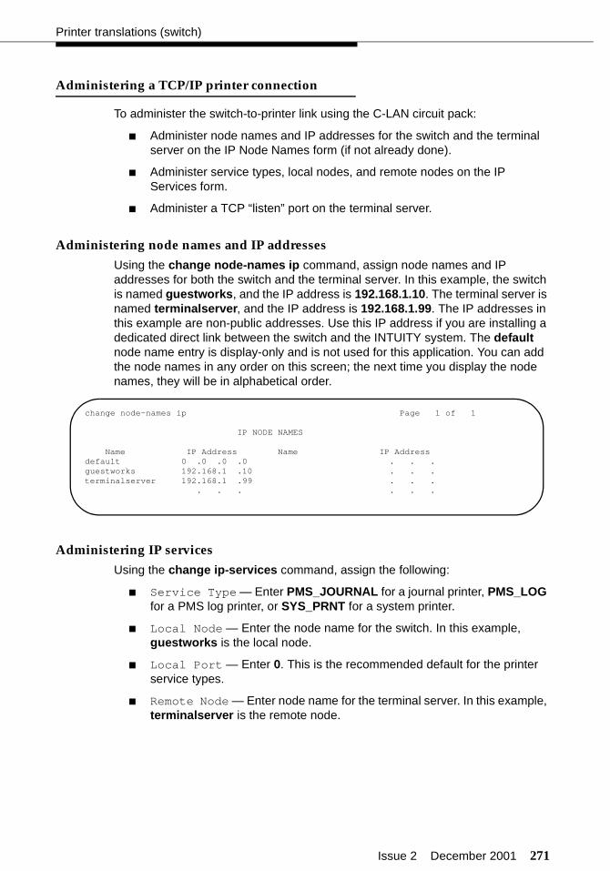
Issue 2 December 2001 271
Printer translations (switch)
Administering a TCP/IP printer connection
To administer the switch-to-printer link using the C-LAN circuit pack:
■ Administer node names and IP addresses for the switch and the terminal server on the IP Node Names form (if not already done).
■ Administer service types, local nodes, and remote nodes on the IP Services form.
■ Administer a TCP “listen” port on the terminal server.
Administering node names and IP addresses
Using the change node-names ip command, assign node names and IP addresses for both the switch and the terminal server. In this example, the switch is named guestworks, and the IP address is 192.168.1.10. The terminal server is named terminalserver, and the IP address is 192.168.1.99. The IP addresses in this example are non-public addresses. Use this IP address if you are installing a dedicated direct link between the switch and the INTUITY system. The default node name entry is display-only and is not used for this application. You can add the node names in any order on this screen; the next time you display the node names, they will be in alphabetical order.
Administering IP services
Using the change ip-services command, assign the following:
■ Service Type — Enter PMS_JOURNAL for a journal printer, PMS_LOG for a PMS log printer, or SYS_PRNT for a system printer.
■ Local Node — Enter the node name for the switch. In this example, guestworks is the local node.
■ Local Port — Enter 0. This is the recommended default for the printer service types.
■ Remote Node — Enter node name for the terminal server. In this example, terminalserver is the remote node.
change node-names ip Page 1 of 1
IP NODE NAMES
Name IP Address Name IP Addressdefault 0 .0 .0 .0 . . .guestworks 192.168.1 .10 . . .terminalserver 192.168.1 .99 . . .
. . . . . .

272 Issue 2 December 2001
Translations and testing
■ Remote Port — Enter the TCP listen port assigned to the terminal server port that is physically connected to the printer. The recommended value for PMS_JOURNAL is 5104; the recommended value for PMS_LOG is 5105; and the recommended value for SYS_PRNT is 5106. The TCP listen port is administered on the terminal server.
■ Protocol Enabled — This field is used only for PMS_JOURNAL and PMS_LOG printers.
On Page 3, you enable the reliable protocol and can adjust the timers and counters used for the reliable protocol. For most applications, you should use the system defaults.
Administering a port on the terminal server
The initial options on the terminal server must be administered before you administer a port (see “Terminal server for asynchronous links” on page 183). Use this procedure when connecting printers to the terminal server.
To administer a port on the terminal server:
1. Select Admin mode > Password and press ENTER.
2. Type iolan and press ENTER.
3. Select port and press ENTER.
4. Type port number, where port number is the port that the adjunct connects to, and press ENTER to view the Port Setup Menu.
change ip-services Page 1 of 3
IP SERVICESService Enabled Local Local Remote RemoteType Node Port Node Port
PMS guestworks 0 terminalserver 5103CDR1 guestworks 0 terminalserver 5101PMS_JOURNAL guestworks 0 terminalserver 5104PMS_LOG guestworks 0 terminalserver 5105SYS_PRNT guestworks 0 terminalserver 5106
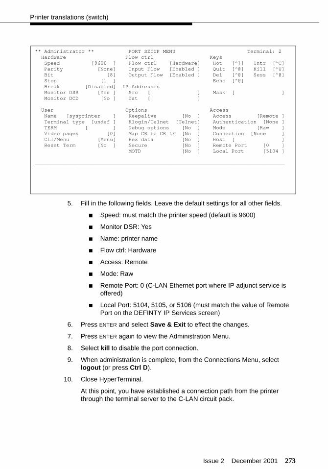
Issue 2 December 2001 273
Printer translations (switch)
5. Fill in the following fields. Leave the default settings for all other fields.
■ Speed: must match the printer speed (default is 9600)
■ Monitor DSR: Yes
■ Name: printer name
■ Flow ctrl: Hardware
■ Access: Remote
■ Mode: Raw
■ Remote Port: 0 (C-LAN Ethernet port where IP adjunct service is offered)
■ Local Port: 5104, 5105, or 5106 (must match the value of Remote Port on the DEFINTY IP Services screen)
6. Press ENTER and select Save & Exit to effect the changes.
7. Press ENTER again to view the Administration Menu.
8. Select kill to disable the port connection.
9. When administration is complete, from the Connections Menu, select logout (or press Ctrl D).
10. Close HyperTerminal.
At this point, you have established a connection path from the printer through the terminal server to the C-LAN circuit pack.
** Administrator ** PORT SETUP MENU Terminal: 2 Hardware Flow ctrl Keys Speed [9600 ] Flow ctrl [Hardware] Hot [^]] Intr [^C] Parity [None] Input Flow [Enabled ] Quit [^@] Kill [^U] Bit [8] Output Flow [Enabled ] Del [^@] Sess [^@] Stop [1 ] Echo [^@] Break [Disabled] IP Addresses Monitor DSR [Yes ] Src [ ] Mask [ ] Monitor DCD [No ] Dst [ ]
User Options Access Name [sysprinter ] Keepalive [No ] Access [Remote ] Terminal type [undef ] Rlogin/Telnet [Telnet] Authentication [None ] TERM [ ] Debug options [No ] Mode [Raw ] Video pages [0] Map CR to CR LF [No ] Connection [None ] CLI/Menu [Menu] Hex data [No ] Host [ ] Reset Term [No ] Secure [No ] Remote Port [0 ] MOTD [No ] Local Port [5104 ]
________________________________________________________________________________
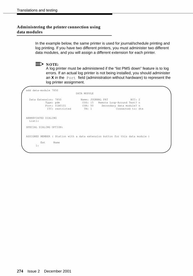
274 Issue 2 December 2001
Translations and testing
Administering the printer connection usingdata modules
In the example below, the same printer is used for journal/schedule printing and log printing. If you have two different printers, you must administer two different data modules, and you will assign a different extension for each printer.
NOTE:A log printer must be administered if the “list PMS down” feature is to log errors. If an actual log printer is not being installed, you should administer an X in the Port field (administration without hardware) to represent the log printer assignment.
add data-module 7850 DATA MODULE
Data Extension: 7850 Name: JOURNAL PRT BCC: 2 Type: pdm COS: 15 Remote Loop-Around Test? n Port: 01B0101 COR: 50 Secondary data module? n
ITC: restricted TN: 1 Connected to: dte
ABBREVIATED DIALING List1:
SPECIAL DIALING OPTION:
ASSIGNED MEMBER ( Station with a data extension button for this data module )
Ext Name 1:

Issue 2 December 2001 275
Printer translations (switch)
Testing the Journal/PMS log or system printer
Using the RS232 Mini-Tester (see the Note on page 5), check the status of the printer connection. The leads marked with an asterisk are controlled by the switch, and the printer controls the other leads. If any of the switch leads are dark, there is no connection.
! CAUTION:After using a mini-tester to check data leads, you MUST remove the mini-tester from the connection. DO NOT leave the mini-tester in-line during actual operation.
If the link is active, the mini-tester should show the following:
The following three test results occur if the link is idle, but the reason for each result is different.
The following will display if the link is not up; try the test journal pms command to start the link. The printer could also be busied out; try the release journal pms command to release the printer.
TD
RTS
DTR
RD*
CTS*DSR*
CD*
green
green
red
green
red
green
green
TD
RTS
DTR
RD*
CTS*DSR*
CD*
red
red
green
redred
greenred
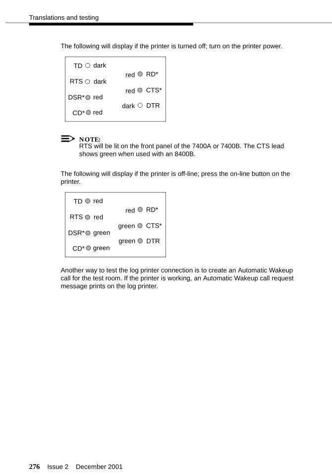
276 Issue 2 December 2001
Translations and testing
The following will display if the printer is turned off; turn on the printer power.
NOTE:RTS will be lit on the front panel of the 7400A or 7400B. The CTS lead shows green when used with an 8400B.
The following will display if the printer is off-line; press the on-line button on the printer.
Another way to test the log printer connection is to create an Automatic Wakeup call for the test room. If the printer is working, an Automatic Wakeup call request message prints on the log printer.
TD
RTS
DTR
RD*
CTS*DSR*
CD*
red
dark
redred
red
dark
dark
TD
RTS
DTR
RD*
CTS*DSR*
CD*
red
red
greengreen
green
red
green

Issue 2 December 2001 277
Printer translations (switch)
Use the status link X command to display the active TCP/IP appliations. X is the TCP/IP link number. In this example of Page 4, the system shows the current activity of the different IP services. Each assigned printer service should show one active session.
status link 1 Page 4 of 4TCP/IP Applications Currently Active
Service Type Sessions
ALARM1 1ALARM2 1CDR1 1CDR2 0DOLAN 0PMS 1PMS_JOURNAL 1PMS_LOG 0SAT 3SYS_PRNT 1
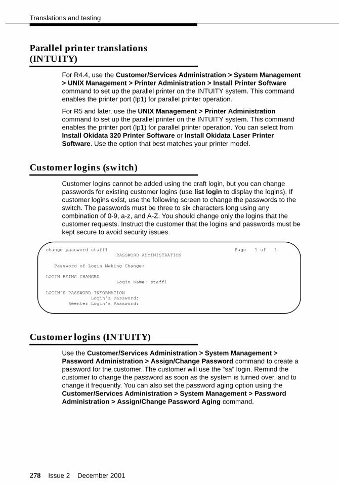
278 Issue 2 December 2001
Translations and testing
Parallel printer translations (INTUITY)
For R4.4, use the Customer/Services Administration > System Management > UNIX Management > Printer Administration > Install Printer Software command to set up the parallel printer on the INTUITY system. This command enables the printer port (lp1) for parallel printer operation.
For R5 and later, use the UNIX Management > Printer Administration command to set up the parallel printer on the INTUITY system. This command enables the printer port (lp1) for parallel printer operation. You can select from Install Okidata 320 Printer Software or Install Okidata Laser Printer Software. Use the option that best matches your printer model.
Customer logins (switch)
Customer logins cannot be added using the craft login, but you can change passwords for existing customer logins (use list login to display the logins). If customer logins exist, use the following screen to change the passwords to the switch. The passwords must be three to six characters long using any combination of 0-9, a-z, and A-Z. You should change only the logins that the customer requests. Instruct the customer that the logins and passwords must be kept secure to avoid security issues.
Customer logins (INTUITY)
Use the Customer/Services Administration > System Management > Password Administration > Assign/Change Password command to create a password for the customer. The customer will use the “sa” login. Remind the customer to change the password as soon as the system is turned over, and to change it frequently. You can also set the password aging option using the Customer/Services Administration > System Management > Password Administration > Assign/Change Password Aging command.
change password staff1 Page 1 of 1PASSWORD ADMINISTRATION
Password of Login Making Change:
LOGIN BEING CHANGEDLogin Name: staff1
LOGIN’S PASSWORD INFORMATIONLogin’s Password:
Reenter Login’s Password:
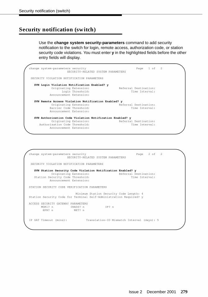
Issue 2 December 2001 279
Security notification (switch)
Security notification (switch)
Use the change system security-parameters command to add security notification to the switch for login, remote access, authorization code, or station security code violations. You must enter y in the highlighted fields before the other entry fields will display.
change system-parameters security Page 1 of 2SECURITY-RELATED SYSTEM PARAMETERS
SECURITY VIOLATION NOTIFICATION PARAMETERS
SVN Login Violation Notification Enabled? yOriginating Extension: Referral Destination:
Login Threshold: Time Interval:Announcement Extension:
SVN Remote Access Violation Notification Enabled? yOriginating Extension: Referral Destination:
Barrier Code Threshold: Time Interval:Announcement Extension:
SVN Authorization Code Violation Notification Enabled? yOriginating Extension: Referral Destination:
Authorization Code Threshold: Time Interval:Announcement Extension:
change system-parameters security Page 2 of 2SECURITY-RELATED SYSTEM PARAMETERS
SECURITY VIOLATION NOTIFICATION PARAMETERS
SVN Station Security Code Violation Notification Enabled? yOriginating Extension: Referral Destination:
Station Security Code Threshold: Time Interval:Announcement Extension:
STATION SECURITY CODE VERIFICATION PARAMETERS
Minimum Station Security Code Length: 4Station Security Code for Terminal Self-Administration Required? y
ACCESS SECURITY GATEWAY PARAMETERSMGR1? n INADS? n IP? nEPN? n NET? n
IP SAT Timeout (mins): Translation-ID Mismatch Interval (days): 5
280 Issue 2 December 2001
Translations and testing
Saving translations (switch)
After you have finished all translations, tested the translations, and verified them with the customer, save the announcements using the save announcements command. When that is finished, save translations using the save translation command. After saving translations, log off using the logoff command.
Creating a backup (INTUITY)
Use the Customer/Services Administration > Backup/Restore > Backup command to create a backup tape for the INTUITY. Follow the instructions displayed on the screen.
Issue 2 December 2001 281
Finishing the switch installation
This section contains procedures that you must complete after you have connected and tested the hospitality adjuncts. The procedures in this section are fully detailed in the appropriate switch installation documents.
Testing the switch
See the appropriate installation document for information about testing the switch:
■ For CMC installations, see Chapter 1 of DEFINITY ECS Installation, Upgrades and Additions for Compact Modular Cabinets.
■ For SCC installations, see the DEFINITY Made Easy Tools.
■ For MCC installations, see the DEFINITY Made Easy Tools.
Installing and wiring telephones and other equipment
See the appropriate installation document for information about installing and wiring telephones and other equipment:
■ For CMC installations, see Chapters 1 and 2 of DEFINITY ECS Installation, Upgrades and Additions for Compact Modular Cabinets.
■ For SCC installations, see the DEFINITY Made Easy Tools.
■ For MCC installations, see the DEFINITY Made Easy Tools.
When installing the attendant consoles, see “Attendant console button layouts (switch)” on page 132 for more information. When installing backup telephones, see “Backup telephone button layouts (switch)” on page 142 for more information.

282 Issue 2 December 2001
Finishing the switch installation
Testing telephones and other equipment
See the appropriate installation document for information about testing telephones and other equipment:
■ For CMC installations, see Chapter 1 of DEFINITY ECS Installation, Upgrades and Additions for Compact Modular Cabinets.
■ For SCC installations, see the DEFINITY Made Easy Tools.
■ For MCC installations, see the DEFINITY Made Easy Tools.
A feature now available is Station Self-Display. This feature allows you to dial a feature access code or press the Inspect button at a display telephone to display the extension number for that telephone. The feature is enabled using the change system-parameters features command. The feature access code is assigned using the change feature-access-codes command.
Turning the system over to the customer
After you have installed and tested the switch and installed adjuncts, and have determined that the system is operating correctly, you will turn control of the system over to the customer. Follow your local customer turnover procedures as determined by your distributor or as determined by the customer’s contract. This turnover should include the following:
■ Do a final save of the translations.
■ Give the customer the following documentation:
— GuestWorks and DEFINITY ECS Hospitality Operations
— DEFINITY ECS Documentation Library (CD)
— INTUITY voice messaging instructions/artwork
— A copy of the dialing plan, a list of the feature access codes, and a list of the trunk access codes
— Customer logins and passwords for the switch and the INTUITY sys-tem.
■ Show the customer how to record announcements for Automatic Wakeup calls or the Automatic Attendant feature.
■ Explain any Call Vectoring procedures that have been administered for the Automated Attendant or Dial by Name features.
Issue 2 December 2001 283
Maintenance
■ Remind the customer to provide information about any new telephone numbers and services to the guests, such as instructions that show guests how to do their own Automatic Wakeup calls and Do Not Disturb requests. The information about those features is in GuestWorks and DEFINITY ECS Hospitality Operations.
■ If the customer has a maintenance contract with Avaya, tell the customer that all trouble calls, whether they involve the switch, the INTUITY AUDIX or INTUITY Lodging, or the INTUITY Lodging Call Accounting, should go to 1-800-242-2121. Outside of the United States and Canada, the customer should call their local Avaya representative.
Maintenance
See the appropriate maintenance document for more information:
■ DEFINITY ECS Maintenance for r
■ DEFINITY ECS Maintenance for csi
■ DEFINITY ECS Maintenance for si

284 Issue 2 December 2001
Finishing the switch installation

Issue 2 December 2001 285
Appendixes
Additional information for technicians is provided in the following appendixes:
■ “Appendix A — Parts list” on page 286
■ “Appendix B — Connector pinouts” on page 288
■ “Appendix C — List PMS down events” on page 289
■ “Appendix D — Homisco call record format” on page 292
■ “Appendix E — Xiox call accounting format” on page 293
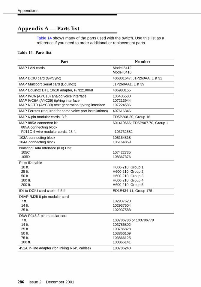
286 Issue 2 December 2001
Appendixes
Appendix A — Parts list
Table 14 shows many of the parts used with the switch. Use this list as a reference if you need to order additional or replacement parts.
Table 14. Parts list
Part Number
MAP LAN cards Model 8412Model 8416
MAP DCIU card (GPSync) 406801647; J1P260AA, List 31
MAP Multiport Serial card (Equinox) J1P260AA1, List 39
MAP Equinox DTE 10/10 adapter, P/N:210068 406983155
MAP IVC6 (AYC10) analog voice interfaceMAP IVC6A (AYC29) tip/ring interfaceMAP NGTR (AYC30) next generation tip/ring interface
106406580107213944107224586
MAP Ferrites (required for some voice port installations) 407616846
MAP 6-pin modular cords, 3 ft. ED5P208-30, Group 16
MAP 885A connector kit885A connecting blockRJ11C 4-wire modular cords, 25 ft.
601419666; ED5P907-70, Group 1
103732582
103A connecting block104A connecting block
105164818105164859
Isolating Data Interface (IDI) Unit105C105D
107422735108367376
PI-to-IDI cable10 ft.25 ft.50 ft.100 ft.200 ft.
H600-210, Group 1H600-210, Group 2H600-210, Group 3H600-210, Group 4H600-210, Group 5
IDI-to-DCIU card cable, 4.5 ft. ED1E434-11, Group 175
D6AP RJ25 6-pin modular cord7 ft.14 ft.25 ft.
102937620102937604102937588
D8W RJ45 8-pin modular cord7 ft.14 ft.25 ft.50 ft.75 ft.100 ft.
103786786 or 103786778103786802103786828103866109103866125103866141
451A in-line adapter (for linking RJ45 cables) 103786240
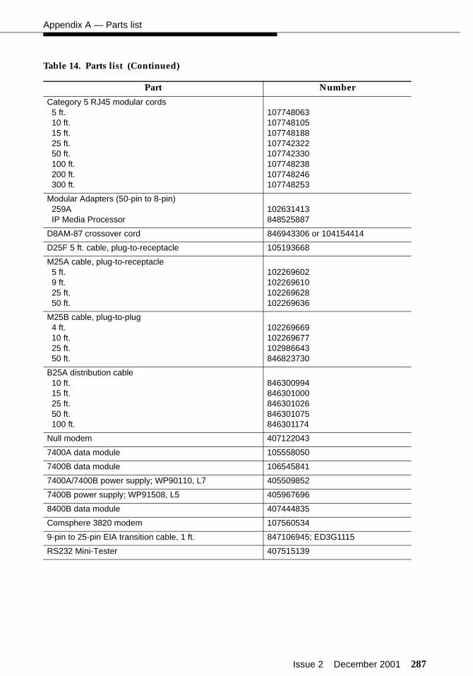
Issue 2 December 2001 287
Appendix A — Parts list
Category 5 RJ45 modular cords5 ft.10 ft.15 ft.25 ft.50 ft.100 ft.200 ft.300 ft.
107748063107748105107748188107742322107742330107748238107748246107748253
Modular Adapters (50-pin to 8-pin)259AIP Media Processor
102631413848525887
D8AM-87 crossover cord 846943306 or 104154414
D25F 5 ft. cable, plug-to-receptacle 105193668
M25A cable, plug-to-receptacle5 ft.9 ft.25 ft.50 ft.
102269602 102269610 102269628 102269636
M25B cable, plug-to-plug4 ft.10 ft.25 ft.50 ft.
102269669 102269677 102986643 846823730
B25A distribution cable10 ft.15 ft.25 ft.50 ft.100 ft.
846300994846301000846301026846301075846301174
Null modem 407122043
7400A data module 105558050
7400B data module 106545841
7400A/7400B power supply; WP90110, L7 405509852
7400B power supply; WP91508, L5 405967696
8400B data module 407444835
Comsphere 3820 modem 107560534
9-pin to 25-pin EIA transition cable, 1 ft. 847106945; ED3G1115
RS232 Mini-Tester 407515139
Table 14. Parts list (Continued)
Part Number
288 Issue 2 December 2001
Appendixes
Appendix B — Connector pinouts
Connections from the Equinox card on the MAP to the hospitality adjuncts (PMS or call accounting) can often cause problems. The following list gives you the pinouts and EIA leads provided when using a D6AP modular cord from the Equinox card to the Equinox 10/10 adapter (P/N:210068, comcode 406983155). These pinouts are on the 25-pin end of the adapter.
■ Pin 2 - TD (transmit data)
■ Pin 3 - RD (receive data)
■ Pin 7 - GND (ground)
■ Pin 8 - DCD (data carrier detect)
■ Pin 20 - DTR (data terminal ready).
This arrangement of EIA is standard in the industry, but these pinouts may become valuable if the adjunct vendor needs to provide a special adapter to interface to this arrangement.
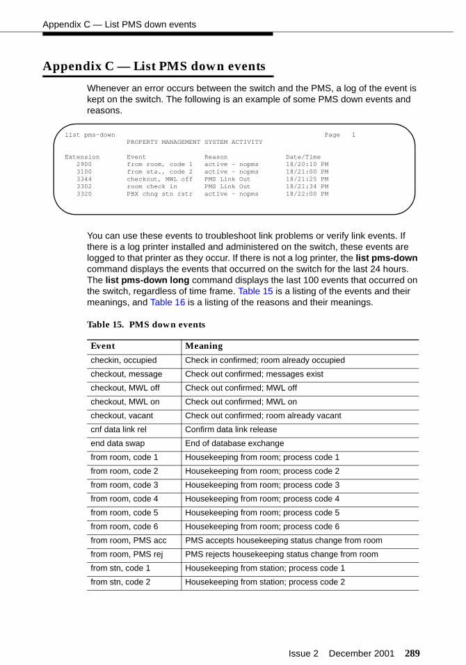
Issue 2 December 2001 289
Appendix C — List PMS down events
Appendix C — List PMS down events
Whenever an error occurs between the switch and the PMS, a log of the event is kept on the switch. The following is an example of some PMS down events and reasons.
You can use these events to troubleshoot link problems or verify link events. If there is a log printer installed and administered on the switch, these events are logged to that printer as they occur. If there is not a log printer, the list pms-down command displays the events that occurred on the switch for the last 24 hours. The list pms-down long command displays the last 100 events that occurred on the switch, regardless of time frame. Table 15 is a listing of the events and their meanings, and Table 16 is a listing of the reasons and their meanings.
Table 15. PMS down events
Event Meaning
checkin, occupied Check in confirmed; room already occupied
checkout, message Check out confirmed; messages exist
checkout, MWL off Check out confirmed; MWL off
checkout, MWL on Check out confirmed; MWL on
checkout, vacant Check out confirmed; room already vacant
cnf data link rel Confirm data link release
end data swap End of database exchange
from room, code 1 Housekeeping from room; process code 1
from room, code 2 Housekeeping from room; process code 2
from room, code 3 Housekeeping from room; process code 3
from room, code 4 Housekeeping from room; process code 4
from room, code 5 Housekeeping from room; process code 5
from room, code 6 Housekeeping from room; process code 6
from room, PMS acc PMS accepts housekeeping status change from room
from room, PMS rej PMS rejects housekeeping status change from room
from stn, code 1 Housekeeping from station; process code 1
from stn, code 2 Housekeeping from station; process code 2
list pms-down Page 1PROPERTY MANAGEMENT SYSTEM ACTIVITY
Extension Event Reason Date/Time2900 from room, code 1 active - nopms 18/20:10 PM3100 from sta., code 2 active - nopms 18/21:00 PM3344 checkout, MWL off PMS Link Out 18/21:25 PM3302 room check in PMS Link Out 18/21:34 PM3320 PBX chng stn rstr active - nopms 18/22:00 PM
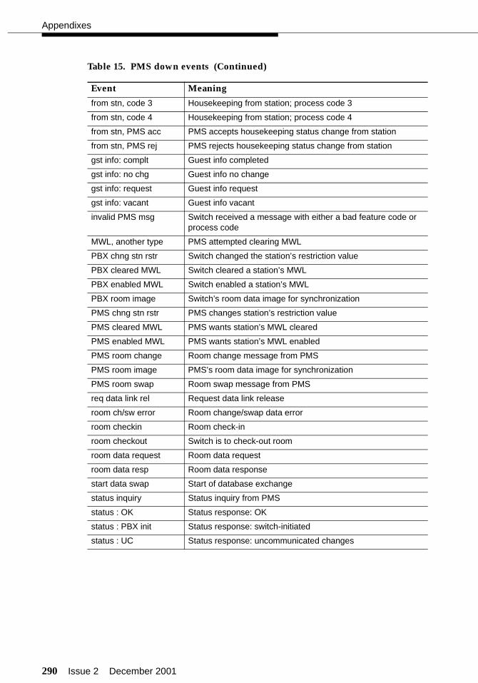
290 Issue 2 December 2001
Appendixes
from stn, code 3 Housekeeping from station; process code 3
from stn, code 4 Housekeeping from station; process code 4
from stn, PMS acc PMS accepts housekeeping status change from station
from stn, PMS rej PMS rejects housekeeping status change from station
gst info: complt Guest info completed
gst info: no chg Guest info no change
gst info: request Guest info request
gst info: vacant Guest info vacant
invalid PMS msg Switch received a message with either a bad feature code or process code
MWL, another type PMS attempted clearing MWL
PBX chng stn rstr Switch changed the station’s restriction value
PBX cleared MWL Switch cleared a station’s MWL
PBX enabled MWL Switch enabled a station’s MWL
PBX room image Switch’s room data image for synchronization
PMS chng stn rstr PMS changes station’s restriction value
PMS cleared MWL PMS wants station’s MWL cleared
PMS enabled MWL PMS wants station’s MWL enabled
PMS room change Room change message from PMS
PMS room image PMS’s room data image for synchronization
PMS room swap Room swap message from PMS
req data link rel Request data link release
room ch/sw error Room change/swap data error
room checkin Room check-in
room checkout Switch is to check-out room
room data request Room data request
room data resp Room data response
start data swap Start of database exchange
status inquiry Status inquiry from PMS
status : OK Status response: OK
status : PBX init Status response: switch-initiated
status : UC Status response: uncommunicated changes
Table 15. PMS down events (Continued)
Event Meaning
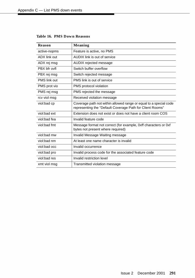
Issue 2 December 2001 291
Appendix C — List PMS down events
Table 16. PMS Down Reasons
Reason Meaning
active-nopms Feature is active, no PMS
ADX link out AUDIX link is out of service
ADX rej msg AUDIX rejected message
PBX bfr ovfl Switch buffer overflow
PBX rej msg Switch rejected message
PMS link out PMS link is out of service
PMS prot vio PMS protocol violation
PMS rej msg PMS rejected the message
rcv viol msg Received violation message
viol:bad cp Coverage path not within allowed range or equal to a special code representing the “Default Coverage Path for Client Rooms”
viol:bad ext Extension does not exist or does not have a client room COS
viol:bad fea Invalid feature code
viol:bad fmt Message format not correct (for example, 0xff characters or 0xf bytes not present where required)
viol:bad mw Invalid Message Waiting message
viol:bad nm At least one name character is invalid
viol:bad occ Invalid occurrence
viol:bad pro Invalid process code for the associated feature code
viol:bad res Invalid restriction level
xmt viol msg Transmitted violation message
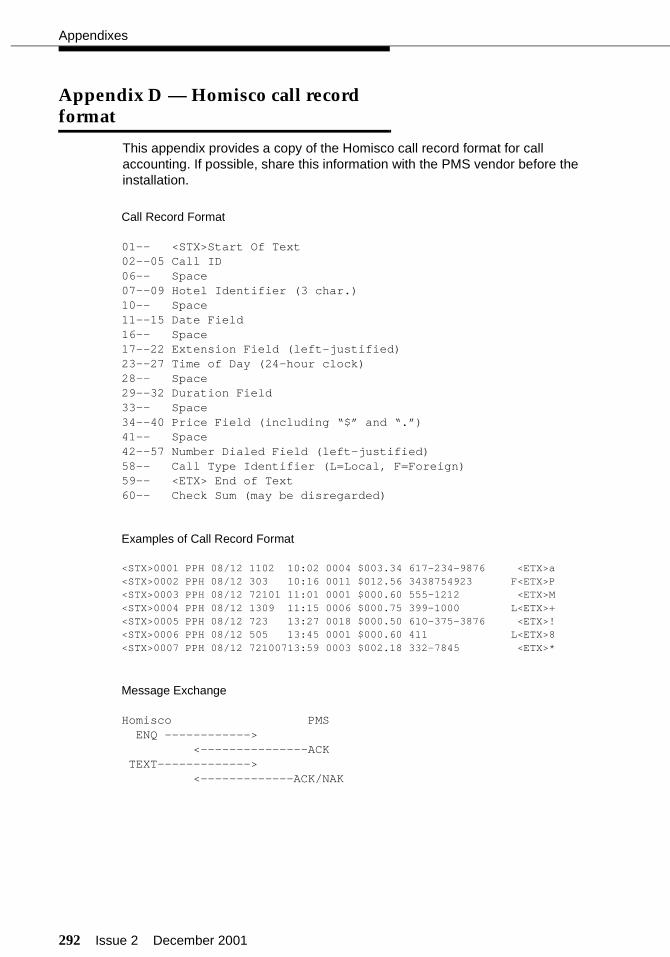
292 Issue 2 December 2001
Appendixes
Appendix D — Homisco call record format
This appendix provides a copy of the Homisco call record format for call accounting. If possible, share this information with the PMS vendor before the installation.
Call Record Format
01-- <STX>Start Of Text02--05 Call ID06-- Space07--09 Hotel Identifier (3 char.)10-- Space11--15 Date Field16-- Space17--22 Extension Field (left-justified)23--27 Time of Day (24-hour clock)28-- Space29--32 Duration Field33-- Space34--40 Price Field (including “$” and “.”)41-- Space42--57 Number Dialed Field (left-justified)58-- Call Type Identifier (L=Local, F=Foreign)59-- <ETX> End of Text60-- Check Sum (may be disregarded)
Examples of Call Record Format
<STX>0001 PPH 08/12 1102 10:02 0004 $003.34 617-234-9876 <ETX>a<STX>0002 PPH 08/12 303 10:16 0011 $012.56 3438754923 F<ETX>P<STX>0003 PPH 08/12 72101 11:01 0001 $000.60 555-1212 <ETX>M<STX>0004 PPH 08/12 1309 11:15 0006 $000.75 399-1000 L<ETX>+<STX>0005 PPH 08/12 723 13:27 0018 $000.50 610-375-3876 <ETX>!<STX>0006 PPH 08/12 505 13:45 0001 $000.60 411 L<ETX>8<STX>0007 PPH 08/12 72100713:59 0003 $002.18 332-7845 <ETX>*
Message Exchange
Homisco PMSENQ ------------>
<---------------ACKTEXT------------->
<-------------ACK/NAK
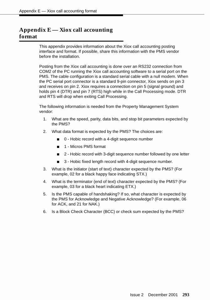
Issue 2 December 2001 293
Appendix E — Xiox call accounting format
Appendix E — Xiox call accounting format
This appendix provides information about the Xiox call accounting posting interface and format. If possible, share this information with the PMS vendor before the installation.
Posting from the Xiox call accounting is done over an RS232 connection from COM2 of the PC running the Xiox call accounting software to a serial port on the PMS. The cable configuration is a standard serial cable with a null modem. When the PC serial port connector is a standard 9-pin connector, Xiox sends on pin 3 and receives on pin 2. Xiox requires a connection on pin 5 (signal ground) and holds pin 4 (DTR) and pin 7 (RTS) high while in the Call Processing mode. DTR and RTS will drop when exiting Call Processing.
The following information is needed from the Property Management System vendor:
1. What are the speed, parity, data bits, and stop bit parameters expected by the PMS?
2. What data format is expected by the PMS? The choices are:
■ 0 - Hobic record with a 4-digit sequence number
■ 1 - Micros PMS format
■ 2 - Hobic record with 3-digit sequence number followed by one letter
■ 3 - Hobic fixed length record with 4-digit sequence number.
3. What is the initiator (start of text) character expected by the PMS? (For example, 02 for a black happy face indicating STX.)
4. What is the terminator (end of text) character expected by the PMS? (For example, 03 for a black heart indicating ETX.)
5. Is the PMS capable of handshaking? If so, what character is expected by the PMS for Acknowledge and Negative Acknowledge? (For example, 06 for ACK, and 21 for NAK.)
6. Is a Block Check Character (BCC) or check sum expected by the PMS?

294 Issue 2 December 2001
Appendixes
The following is a sample of Format 0 (Hobic with 4-digit sequence number):
0001 HTL 02/29 501 13:32 0009 $002.50 650-555-1212
The following table describes this format:
Position Length Description
1 4 Message Sequence Number - right justified, 0 filled
6 3 Property Name Acronym - up to 3 alpha characters speci-fied by the user
10 5 Date - MM/DD
16 5 Extension Number - left justified, space filled
22 5 Call Start Time - HH:MM
28 4 Duration in Minutes - right justified, 0 filled
33 7 Price - fixed format, 0 filled
41 14 Dialed Digits - variable length field consisting of a dialed digit string of up to 12 characters

Issue 1 December 2001 295
INIndex
Numerics
103A modular connecting blocks, 33, 37105C IDI, 29105D IDI, 293820 modem, 1027400A data module options, 70, 80, 907400B data module options, 71, 81, 918400B data module options, 69, 79, 89885A connector kit, 33
A
Abbreviated Dialing, 129, 134about this handbook, xvactivate the switch, 12adjunct supervision, 241alarm management, 104alerting, 137analog caller ID, 150announcements, 159ASCII mode, 190Attendant Backup, 136, 139, 142Attendant Call Pickup, 142attendant console, 131, 132
permissions, 115queue priority, 138
Attendant Split Swap, 133Attendant Vectoring, 178AUDIX subscribers, 146Automated Attendant, 1, 176Automatic Selection of DID Numbers, 169Automatic Wakeup options, 174Avaya Site Administration, 8, 11
B
backup on INTUITY, 280backup telephone, 142billing considerations for faxes, 128bus bridge, 16, 215button layout
attendant console, 132telephones, 142
buttonsAttendant Call Pickup, 142Automatic Wakeup, 134Automatic Wakeup printer alarm, 134CDR alarm, 134check-in, 134check-out, 134Controlled Restrictions, 134Coverage Message Retrieval, 135Crisis Alert, 134date/time, 135delete message, 135DID view, 133directory, 134display, 135Do Not Disturb, 134failed wakeups, 134, 142forced release, 134Hold, 134inspect, 135maid status, 134Message Waiting activation, 133, 142Message Waiting deactivation, 133, 142next, 135Night Service, 134normal, 135occupied rooms, 134PMS alarm, 134PMS printer alarm, 134position busy, 134split, 133Split Swap, 133system printer alarm, 135timer, 135translations, 132trunk ID, 134VIP retry, 134VIP wakeup, 134
C
cablinghospitality adjuncts, 18INTUITY Lodging Call Accounting-to-PMS, 72INTUITY Lodging-to-PMS, 39MAP remote access, 102Mode Code Integration, 32overall connectivity, 20parallel printers, 97serial printers, 84switch-to-call accounting, 44, 48, 52, 56, 60, 64
data modules, 67switch-to-INADS, 98switch-to-INTUITY (Mode Code Signaling), 31
Index
296 Issue 1 December 2001
cabling, (continued)switch-to-INTUITY (X.25), 29switch-to-INTUITY voice ports, 32switch-to-PMS, 75switch-to-voice messaging (TCP/IP), 25voice ports, 32Xiox call accounting-to-PMS, 74
call accounting, 267link parameters, 262
Call Forwarding, 116guest message retrieval, 246
call record formatHomisco, 292Xiox, 293
Call Vectoring, 176, 179, 282caller ID, 150
message waiting indication, 151calls in queue warning, 136CDR, 44, 48, 52, 56, 60, 64, 168, 262, 266
reports, 168, 263translations, 262
CE marks, 4Center of Excellence, 14, 100, 109check-in/check-out, 208checklist
installation, 4miscellaneous translations, 107switch-to-voice messaging translations, 214translations, 106
C-LAN, 27, 28class of restriction, 117class of service, 115, 124client room, 115, 116
coverage path configuration, 189Comsphere 3820, 102connector pinouts, 288console, 131
permissions, 116Controlled Restrictions, 134, 200, 212
configuration, 189testing, 212translations, 200
conventions, xvicountry options, 14coverage path configuration, 189coverage paths, 246Crisis Alert, 134, 164
ARS pattern, 164, 165button assignment, 134display telephone, 166every user responds, 166pager, 166translations, 164
crossover cable, 26
crossover wiring, 28Custom Selection of DID Numbers, 169customer
documentation, 282logins, 278turnover, 282
D
daily wakeup, 174Data Modules, 198data modules, 69, 70, 71, 79, 80, 81, 89, 90, 91, 198data privacy, 116database swap, 207date and time, 15, 108daylight savings time rules, 15default language, 254, 256default translation card, 12delete digit, 191Dial by Name, 109, 179dial plan, 110, 111
first digit, 110second digit, 110
DID numbers, 169digit deletion, 191digit insertion, 191digit to insert/delete, 110, 191digital line circuit packs, 24display calling number for room to room caller ID
calls, 150display room information in call display, 149displaying a telephone’s extension, 282distinctive audible alerting, 241dual wakeup, 174duplicate command, 147, 242
E
electromagnetic compatibility standards, 3emergency access redirection extension, 163Emergency Access to Attendant, 163Equinox pinouts, 288equipment layout, 7equipment room, 7ethernet data module, 218extension to receive failed wakeup LWC
messages, 174external alert port, 136
Index
Issue 1 December 2001 297
F
failed wakeup button, 134, 142failed wakeup messages, 174fax billing considerations, 128fax extension, 249fax parameters, 127faxes forwarded from guest mailbox, 128feature access codes, 112feature overview, 1ferrites, 33floor plan, 7forward PMS messages to INTUITY Lodging, 253,
255forwarding faxes, 128
G
guestinformation display, 149mailboxes, 158, 260message retrieval, 245rooms, 147
GuestWorks interface link, 253
H
hardware options, xviiHomisco, 6, 18, 44, 56, 67, 139, 262, 292hospitality
customer options, 17parameters, 189
housekeeperID digits, 199information configuration, 189
housekeeping status, 198testing, 213translations, 198
hunt groups, 243hunt-to stations, 153
I
ICLID, 150IDI, 30INADS, 99, 100, 102
alarm origination, 104
insert digit, 191insert/delete digit, 110, 191installation
cabinet, 10checklist, 4management interface, 11overview, 3telecommunications cabling, 10telephones and other equipment, 281
integrated link, 253INTUITY Lodging Call Accounting, 18, 44, 56, 72, 97,
139, 262INTUITY Lodging Call Accounting-to-PMS link
testing, 267translations, 267
INTUITY Lodging voice messaging, 18INTUITY Lodging-to-PMS link
testing, 258translations, 252
INTUITY system parameters, 125IP addresses, 193, 216, 222, 271IP interfaces, 217IP routes, 220IP services, 194, 271Isolating Data Interface, 30
J
journal/log printerstesting, 95, 275translations, 268
journal/schedule printer, 19, 86, 88journal/schedule printer endpoint, 268
L
lamps on for new messages, 158, 256LAN circuit card, 223languages, 254, 256layout, 7LDG, 257LEDs, 147link integration, 253list PMS down events, 289Listed Directory Numbers, 126, 130log printer, 19, 86, 88logical channel, 235, 236logins, 278lost PMS messages, 190LWC activation, 241LWC reception, 241
Index
298 Issue 1 December 2001
M
maid statustesting, 213translations, 198
mailboxesguest room, 158office staff subscribers, 146
maintenance, 283management interface, 11mapping phone numbers to services, 249message center, 244message lamp control, 257message retrieval, 245Message Waiting
configuration, 189indicator, 147testing, 209
mini-tester, 5INTUITY Lodging-to-PMS link, 42, 258journal/log printers, 95printers, 275switch-to-call accounting link, 46, 50, 54, 58, 62,
65switch-to-PMS link, 82, 202
Mode Code Integration, 2, 31, 32, 39, 238, 252modems, 102multiple locations, 16
N
neon lamps, 147Netcon, 197
testing, 204translations, 197
no answer timeout, 137node names, 193, 216, 271number of digits from PMS, 191number of emergency calls allowed in attendant
queue, 163number of housekeeper ID digits, 199
O
offer categories, 1off-hook alert, 116, 163Okidata model ML321T printer options, 92, 93
Okidata printers, 7, 85, 87options
572 printer, 92, 937400A for call accounting, 707400A for PMS, 807400A for printers, 907400B for call accounting, 717400B for PMS, 817400B for printers, 918400B for call accounting, 698400B for PMS, 798400B for printers, 89Okidata printers, 92, 93
P
packet gateway, 30Paradyne, 103parallel printers, 97
translations, 278parts, 5, 286passwords, 17, 250, 278
administrator, 250attendant, 250craft, 14
PBX extension to channel, 247phone number mapping, 249ping, 226pinouts, 288PMS
ASCII mode, 190communication parameters, 80down, 289endpoint, 189event IDs on the INTUITY, 259integration parameters, 257Link Acknowledgement Timeout, 190link acknowledgement timeout, 190link maximum retransmission requests, 190link maximum retransmissions, 190link parameters, 190log printer endpoint, 268status, 205take down link for lost messages, 190testing, 205
prefixed extensions, 191printer
communication parameters, 90options, 92, 93parallel, 97system, 19translations, 268
Index
Issue 1 December 2001 299
processorchannels, 219, 233interface, 231interface link, 30, 231, 234
protocol for caller ID analog terminals, 150protocol mode, 190
Q
queue length, 243queue priority, 138
R
reasons for reissue, xvireboot INTUITY, 225Recorded Announcements, 159recorded announcements, 159related documents, xviiremote maintenance board, 102reports, 270room status definitions, 199routing extension on unavailable voice
synthesis, 175
S
saving translations, 105, 280scheduling reports, 270security notification, 279services to channels, 247site planning, 6software packages, xviispecial applications, 109speech synthesizer circuit packs, 162Split Swap, 133stand-alone interface link, 255standards
electromagnetic compatibility, 3station hunt before coverage, 152, 154station hunting, 153station self-display, 282stations
guest rooms, 147office staff, 139
subscribers, 146Suite Check-In, 152support helpline, 283switch interface on INTUITY, 224switch port, 225, 235, 236
switch tests, 281switch type, 224switch/INTUITY/PMS link integration, 39, 253, 255switchhook flash, 240, 241switch-to-call accounting link
testing, 46, 50, 54, 58, 62, 65, 266translations, 262
switch-to-PMS linktesting, 82, 201translations, 189
switch-to-voice messaging linktesting, 251translations, 214
system parameters, 125system printer
testing, 275translations, 268
T
TAAS, 136tape backup, 280TCP/IP on INTUITY, 222TCP/IP signaling, 25, 215technical support, xx, 283
Xiox, 6telephones, 282terminal server, 183test equipment, 5testing, 105
7400A, 2048400B, 204check-in/check-out, 208Controlled Restrictions, 212database swap, 207housekeeping status, 213INTUITY Lodging Call Accounting-to-PMS
link, 267INTUITY Lodging-to-PMS link, 258journal/log printers, 95, 275Message Waiting, 209Netcon, 204ping, 226PMS, 205switch-to-call accounting link, 42, 46, 50, 54, 58,
62, 65, 266switch-to-INTUITY link, 251switch-to-PMS link, 82, 201system printer, 275TCP/IP link, 226telephones and other equipment, 282voice mailboxes, 260voice ports, 251X.25 link, 236
Index
300 Issue 1 December 2001
time and date, 15, 108tip/ring card, 32, 37TN799B, 27Toll Restriction, 200training, xvtranslation card, 12translations, 105, 193
Abbreviated Dialing, 129alarm management, 104announcements, 159Attendant Backup, 136attendant console, 131Attendant Vectoring, 178automated attendant, 176billing for forwarded faxes, 128bus bridge, 16, 215buttons, 132
attendant console, 132backup telephone, 142
call accounting link parameters, 262Call Forwarding for guest message retrieval, 246Call Vectoring, 176caller ID, 150CDR, 262checklist, 106class of restriction, 117class of service, 115, 124console, 131console queue priority, 138Controlled Restrictions, 200country options, 14coverage paths, 246Crisis Alert, 164customer logins, 278date and time, 15, 108daylight savings time rules, 15default language, 256Dial by Name, 109, 179dial plan, 110, 111DID numbers for guest rooms, 169Emergency Access to Attendant, 163ethernet data module, 218fax extension, 249fax parameters, 127feature access codes, 112guest message retrieval, 245guest room mailboxes, 158hospitality
customer options, 17parameters, 189
housekeeping status, 198hunt groups, 243INADS, 100INTUITY Lodging Call Accounting-to-PMS, 267INTUITY Lodging-to-PMS, 252INTUITY system parameters, 125
translations, (continued)IP addresses, 216, 222, 271IP interfaces, 217IP routes, 220IP services, 194, 271LAN circuit card, 223languages, 254, 256link data modules, 198Listed Directory Numbers, 126, 130logins, 278mailboxes, 146, 158miscellaneous, 107Mode Code signaling, 238multiple locations, 16Netcon, 197node names, 193, 216, 271parallel printers, 278passwords, 17, 250, 278PBX extension to channel, 247phone number mapping, 249printer, 268printer endpoints, 268processor channels, 219, 233processor interface link, 231reboot INTUITY, 225recorded announcements, 159remote maintenance, 100saving translations, 17, 280security notification, 279serial printer, 268services to channels, 247services to phone number mapping, 249station hunt before coverage, 154station hunting, 153stations, 139subscribers, 146Suite Check-In, 152switch interface on INTUITY, 224, 235, 236switch type, 224, 234switch/INTUITY/PMS link integration, 253, 255switch-to-call accounting, 262switch-to-INTUITY, 214switch-to-PMS, 189system printer endpoint, 269TCP/IP link, 193TCP/IP on INTUITY, 222TCP/IP signaling, 215terminal server, 183, 195, 264, 272time and date, 108trunk groups, 168Trunk-to-Trunk Transfer, 182voice ports on INTUITY, 247voice ports to INTUITY AUDIX, 240wakeup options, 174X.25 data module, 231X.25 signaling, 231
Index
Issue 1 December 2001 301
Trunk Groups, 168trunk groups, 168Trunk-to-Trunk Transfer, 182
V
VIP wakeup, 174voice mailboxes, 260voice ports, 32, 240, 247
hunt groups, 243status, 251testing, 251translations, 240, 247
W
Wakeup Activation via Tones, 174wakeup options, 174
X
X.25 data module, 231X.25 signaling, 29, 231Xiox, 6, 18, 48, 60, 67
posting interface and format, 293technical support, 6

Index
302 Issue 1 December 2001