Embed Size (px)
Citation preview
Please keep this guide carefully with the product.
NE3390-157AFibre Channel (1ch)
Fibre Channel Controller (1ch)User's Guide
PrefaceThank you very much for purchasing the NE3390-157A Fibre Channel Controller (1ch).
This is a guide to the safe and proper use of the NE3390-157A Fibre Channel Controller (1ch) (hereafter, this product). Be sure to read this guide before handling this product. Please refer to this document if there is something that you do not understand or a problem occurs while using this product. Store this guide close to this product for easy reference.
For an explanation on the handling of the basic processing unit (hereafter, Computer) that this product is installed in, please refer to the User's Guide that came with the basic processing unit. In addition, be sure to read the sections entitled "Safety Precautions" and "Precautions on Use" before handling this product.

Concerning trademarks
Microsoft and its logo, Windows and Windows Server are all registered trademarks of Microsoft Corporation in the United States of America and/or other countries.Emulex and its logo and OneConnect and LightPulse are all registered trademarks of Emulex Corporation in the United States of America and/or other countries.All other product names mentioned are trademarks or registered trademarks of their respective owners and should be treated as such.
Note
(1)No part of this document may be reproduced without consent.(2)The content of this document may be changed without prior notice.(3)No part of this document may be revised or reproduced without the permission of NEC Corporation.(4)Although great care has been taken to ensure the accuracy and completeness of the information contained
in this document, please contact the dealer you purchased this product from if you have any questions or find mistakes or omissions.
(5)Notwithstanding the preceding item (4), NEC Corporation shall not be liable for any consequences resulting from the use of this product,.
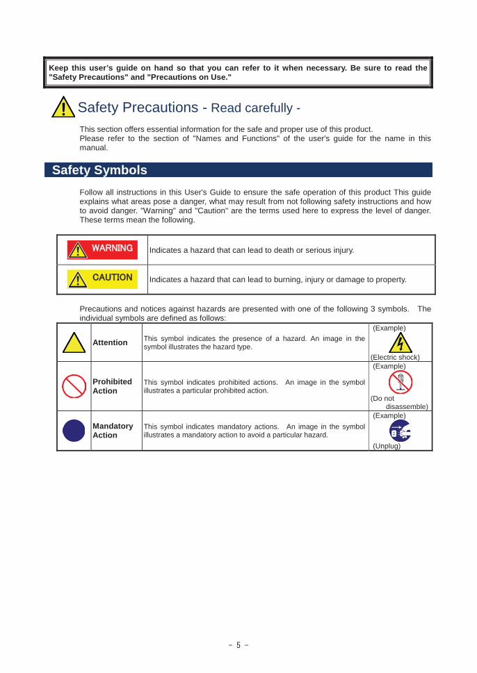
Keep this user’s guide on hand so that you can refer to it when necessary. Be sure to read the "Safety Precautions" and "Precautions on Use."
Safety Precautions - Read carefully -This section offers essential information for the safe and proper use of this product.Please refer to the section of "Names and Functions" of the user's guide for the name in this manual.
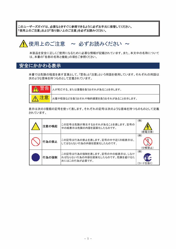
Safety SymbolsFollow all instructions in this User's Guide to ensure the safe operation of this product This guide explains what areas pose a danger, what may result from not following safety instructions and how to avoid danger. "Warning" and "Caution" are the terms used here to express the level of danger. These terms mean the following.
Indicates a hazard that can lead to death or serious injury.
Indicates a hazard that can lead to burning, injury or damage to property.
Precautions and notices against hazards are presented with one of the following 3 symbols. The individual symbols are defined as follows:
Attention This symbol indicates the presence of a hazard. An image in the symbol illustrates the hazard type.
(Example)
(Electric shock)
Prohibited Action
This symbol indicates prohibited actions. An image in the symbol illustrates a particular prohibited action.
(Example)
(Do notdisassemble)
Mandatory Action
This symbol indicates mandatory actions. An image in the symbol illustrates a mandatory action to avoid a particular hazard.
(Example)
(Unplug)

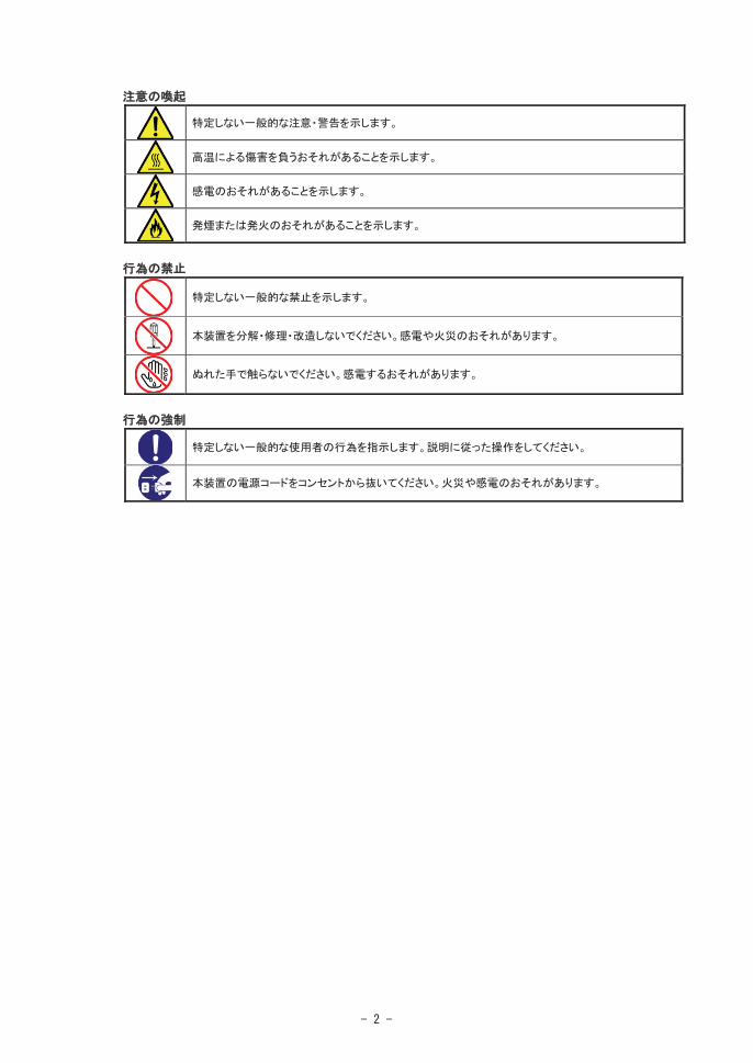
Attention
Indicates general warnings and cautions.
Indicates a hazard that can lead to burns.
Indicates a hazard that can lead to electric shock.
Indicates a hazard that can lead to fire.
Prohibited Action
Indicates a general prohibition.
Indicates prohibition of disassembly or modification.
Do not touch with wet hand. Otherwise, an electric shock may be caused.
Mandatory Action
Indicates general instruction for users.
Indicates that you must unplug from the electrical outlet.
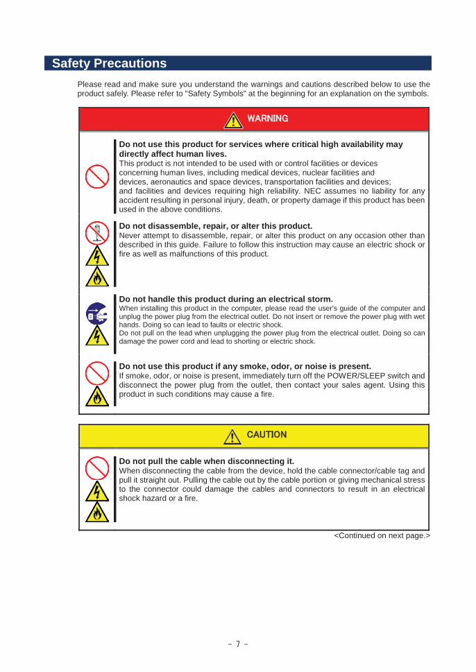
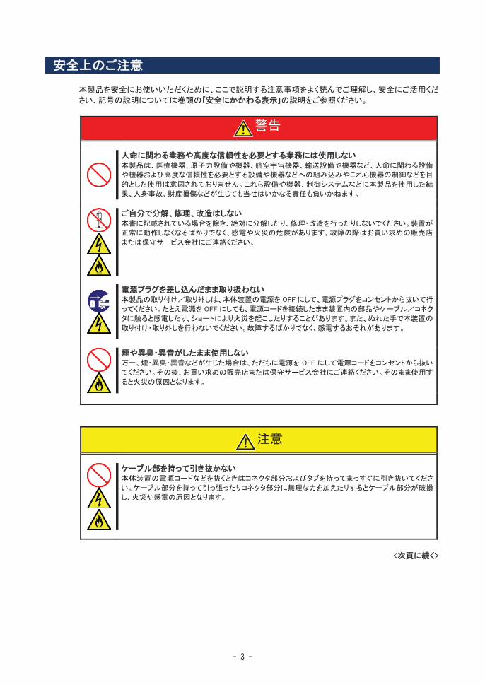
Safety PrecautionsPlease read and make sure you understand the warnings and cautions described below to use the product safely. Please refer to "Safety Symbols" at the beginning for an explanation on the symbols.
Do not use this product for services where critical high availability may directly affect human lives.This product is not intended to be used with or control facilities or devicesconcerning human lives, including medical devices, nuclear facilities anddevices, aeronautics and space devices, transportation facilities and devices;and facilities and devices requiring high reliability. NEC assumes no liability for any accident resulting in personal injury, death, or property damage if this product has been used in the above conditions.
Do not disassemble, repair, or alter this product.Never attempt to disassemble, repair, or alter this product on any occasion other than described in this guide. Failure to follow this instruction may cause an electric shock or fire as well as malfunctions of this product.
Do not handle this product during an electrical storm. When installing this product in the computer, please read the user's guide of the computer and unplug the power plug from the electrical outlet. Do not insert or remove the power plug with wet hands. Doing so can lead to faults or electric shock.Do not pull on the lead when unplugging the power plug from the electrical outlet. Doing so can damage the power cord and lead to shorting or electric shock.
Do not use this product if any smoke, odor, or noise is present.If smoke, odor, or noise is present, immediately turn off the POWER/SLEEP switch and disconnect the power plug from the outlet, then contact your sales agent. Using this product in such conditions may cause a fire.
Do not pull the cable when disconnecting it.When disconnecting the cable from the device, hold the cable connector/cable tag and pull it straight out. Pulling the cable out by the cable portion or giving mechanical stress to the connector could damage the cables and connectors to result in an electrical shock hazard or a fire.
<Continued on next page.>
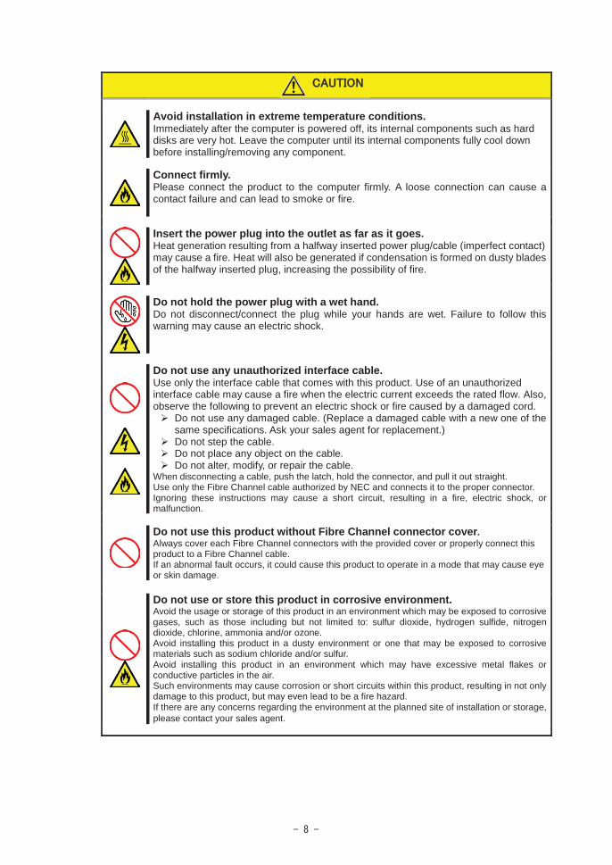
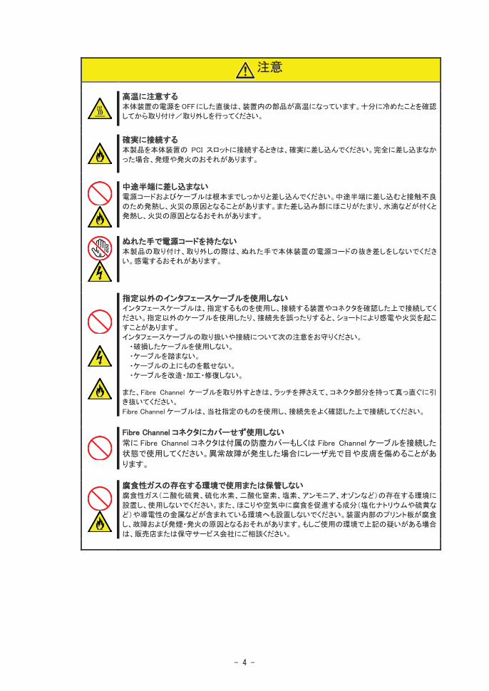
Avoid installation in extreme temperature conditions.Immediately after the computer is powered off, its internal components such as hard disks are very hot. Leave the computer until its internal components fully cool down before installing/removing any component.
Connect firmly.Please connect the product to the computer firmly. A loose connection can cause a contact failure and can lead to smoke or fire.
Insert the power plug into the outlet as far as it goes.Heat generation resulting from a halfway inserted power plug/cable (imperfect contact) may cause a fire. Heat will also be generated if condensation is formed on dusty blades of the halfway inserted plug, increasing the possibility of fire.
Do not hold the power plug with a wet hand.Do not disconnect/connect the plug while your hands are wet. Failure to follow this warning may cause an electric shock.
Do not use any unauthorized interface cable.Use only the interface cable that comes with this product. Use of an unauthorized interface cable may cause a fire when the electric current exceeds the rated flow. Also, observe the following to prevent an electric shock or fire caused by a damaged cord.
Do not use any damaged cable. (Replace a damaged cable with a new one of the same specifications. Ask your sales agent for replacement.)Do not step the cable.Do not place any object on the cable.Do not alter, modify, or repair the cable.
When disconnecting a cable, push the latch, hold the connector, and pull it out straight.Use only the Fibre Channel cable authorized by NEC and connects it to the proper connector.Ignoring these instructions may cause a short circuit, resulting in a fire, electric shock, ormalfunction.
Do not use this product without Fibre Channel connector cover.Always cover each Fibre Channel connectors with the provided cover or properly connect this product to a Fibre Channel cable.If an abnormal fault occurs, it could cause this product to operate in a mode that may cause eye or skin damage.
Do not use or store this product in corrosive environment.Avoid the usage or storage of this product in an environment which may be exposed to corrosive gases, such as those including but not limited to: sulfur dioxide, hydrogen sulfide, nitrogen dioxide, chlorine, ammonia and/or ozone.Avoid installing this product in a dusty environment or one that may be exposed to corrosive materials such as sodium chloride and/or sulfur.Avoid installing this product in an environment which may have excessive metal flakes or conductive particles in the air.Such environments may cause corrosion or short circuits within this product, resulting in not only damage to this product, but may even lead to be a fire hazard.If there are any concerns regarding the environment at the planned site of installation or storage, please contact your sales agent
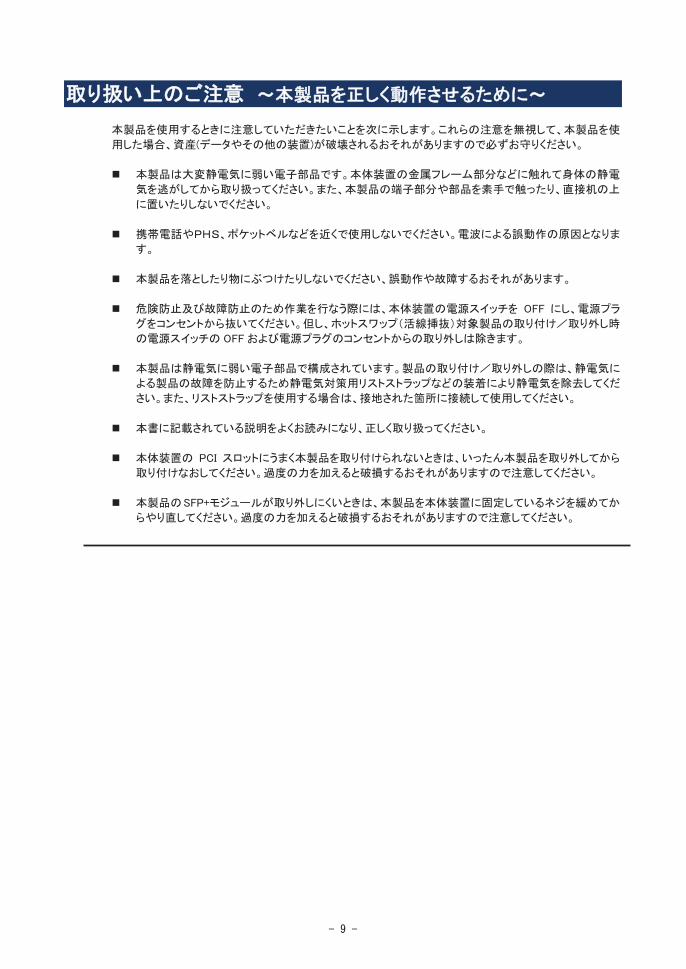

Precautions on Use - Operating this product properly -The following precautions must be observed when using this product. Ignoring these precautions while using this product will result in the destruction of assets (data and other devices). Please observe the following.
This product is sensitive to static electricity. Please discharge any static electricity by touching a metalobject such as the metal frame of the computer before handling the product. Moreover, do not touch the contacts of the product, or place the product on a desk.
Turn off the cellular phone or pager. Radio interference may cause malfunctions of this product.
Do not drop or hit the product. Doing so can lead to malfunction or failure.
To avoid electric hazard and malfunction, be sure to turn off the Power switch of this product and unplug the power cord from an outlet before carrying out the work. However, there is no need to do this if the internal optional device is hot-swappable.
This internal optional device consists of static-sensitive electronic components. To avoid failures caused by static electricity when installing or uninstalling the internal optional device, wear an anti-static wrist strap on your wrist and provide earthing before carrying out the work. And also connect a wrist strap to earth ground when you wear a wrist strap.
Please read this guide , and handle the product correctly.
Please read the user's guide of the computer before connecting this product. When connecting the product, insert the product firmly into the PCI slot. If this product is not correctly connected to the PCI slot of computer, remove the product and connect it again. Using excessive force can lead to damage.
When remove the SFP+ module firmly from the product, screw down, release this product from the PCI slot and remove again. Using excessive force can lead to damage.

FCC Compliance Information StatementThis equipment has been tested and found to comply with the limits for a Class Adigital device, pursuant to Part 15 of the FCC Rules. These limits are designedto provide reasonable protection against harmful interference when the equipmentis operated in a commercial environment. This equipment generates, uses, and canradiate radio frequency energy and, if not installed and used in accordance withthe instruction manual, may cause harmful interference to radio communications.Operation of this equipment in a residential area is likely to cause harmful interference in which case the user will be required to correct the interference at his own expense.
Industry Canada Class A Emission Compliance Statement/Avis de conformité à la réglementation d‘Industrie Canada:CAN ICES-3(A)/NMB-3(A)
CE StatementWarning: This is a Class A product. In a domestic environment this product may cause radio interference in which case the user may be required to take adequate measures.
BSMI Statement (for Taiwan)
KC Statement (for South Korea)
Registration No. : KCC-REM-EMU-P005947Basic Model Number : P005947Registrant : EMULEX CORPORATIONEquipment Name : OneConnect / LightPulse HBAManufacturer : EMULEX CORPORATIONCountry of Origin : China or Thailand or Malaysia or United States of America
RoHS StatementThis product is RoHS compliant.
This product is classified as a CLASS 1 LASER PRODUCT.
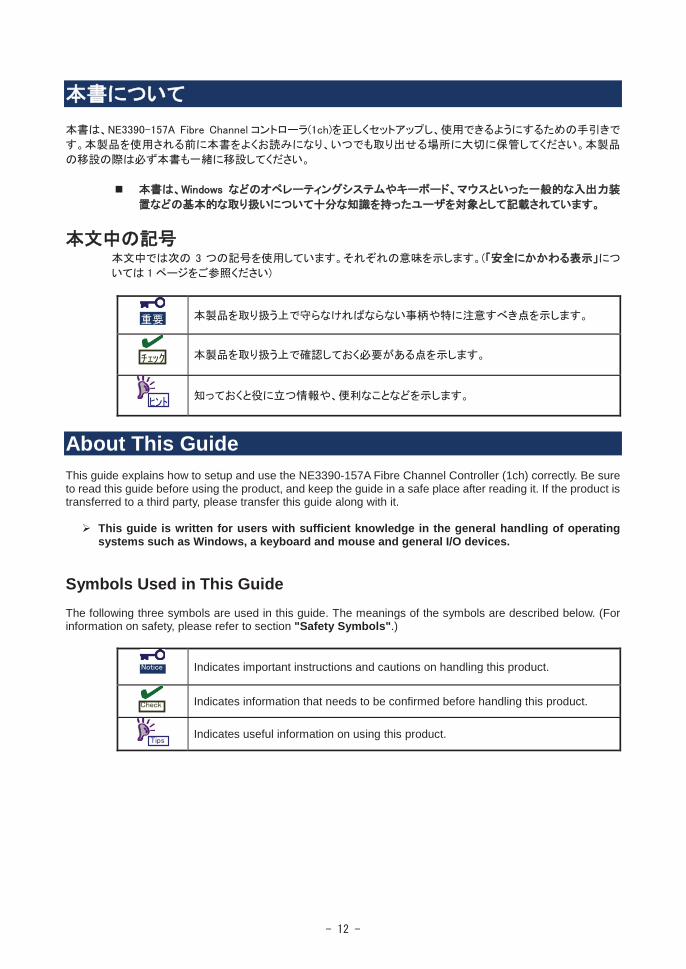
About This GuideThis guide explains how to setup and use the NE3390-157A Fibre Channel Controller (1ch) correctly. Be sure to read this guide before using the product, and keep the guide in a safe place after reading it. If the product is transferred to a third party, please transfer this guide along with it.
This guide is written for users with sufficient knowledge in the general handling of operating systems such as Windows, a keyboard and mouse and general I/O devices.
Symbols Used in This GuideThe following three symbols are used in this guide. The meanings of the symbols are described below. (For information on safety, please refer to section "Safety Symbols".)
Indicates important instructions and cautions on handling this product.
Indicates information that needs to be confirmed before handling this product.
Indicates useful information on using this product.
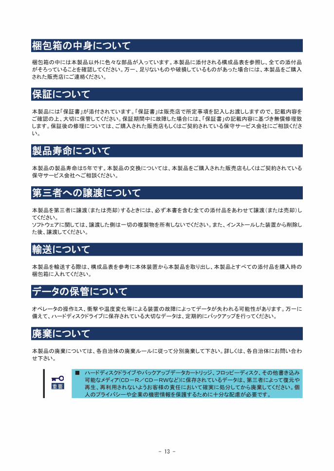

Packing Box ContentsThere are various other accessories included in the packing box besides this product. Please refer to the packing list accompanying the box to make sure that all parts are included. Contact the dealer that you bought this product from if any parts are missing or damaged.
LifetimeThis product has a product lifetime of five years.The holding period for replacement parts is five years from production.
Transferring Ownership to a Third PartyWhen transferring ownership or selling this product to a third party, be sure to pass on this guide and all accessories together with this product.
The party transferring or selling this product must transfer all software and maintain no copies. As well, all installed software must be deleted before this product is transferred or sold.
TransportationWhen transporting this product, please refer to the packing list to remove this product from the basic processing unit and repack it and all of its accessories into the original packing box.
Storing DataData may be lost through a device malfunction due to human error, physical shock, temperature change or other means. To prevent this, be sure to regularly backup essential data saved on the hard disk.
DisposalDispose of this cage according to governing regulations. Contact your local government for details.
Dispose the data saved in hard disks, backup data cartridges, floppy disks, and other data acceptable media (such as CD-R and CD-RW) securely in the customer’s responsibility so that the data may not be restored, reproduced, and/or reused by third parties. Take sufficient notes to protect personal privacy and corporate secret information.

........................................................................................................................... 1
.................................................................................................................................. 3 .................................................................... 9
........................................................................................................................................ 12 ....................................................................................................................................... 12
......................................................................................................................... 13 ........................................................................................................................................ 13
................................................................................................................................. 13 ...................................................................................................................... 13
........................................................................................................................................ 13 .......................................................................................................................... 13
........................................................................................................................................ 13
............................................................................................................................................... 17
................................................................................................................................. 17
.............................................................................................................. 21 ........................................................................................................................... 23
.............................................................................................................. 25 ................................................................................................................ 26
............................................................................................................................ 27
.............................................................................................................................................. 29
..................................................................................................................................... 30 ...................................................................................................................................... 38
............................................................................................................. 42
............................................................................................................... 44
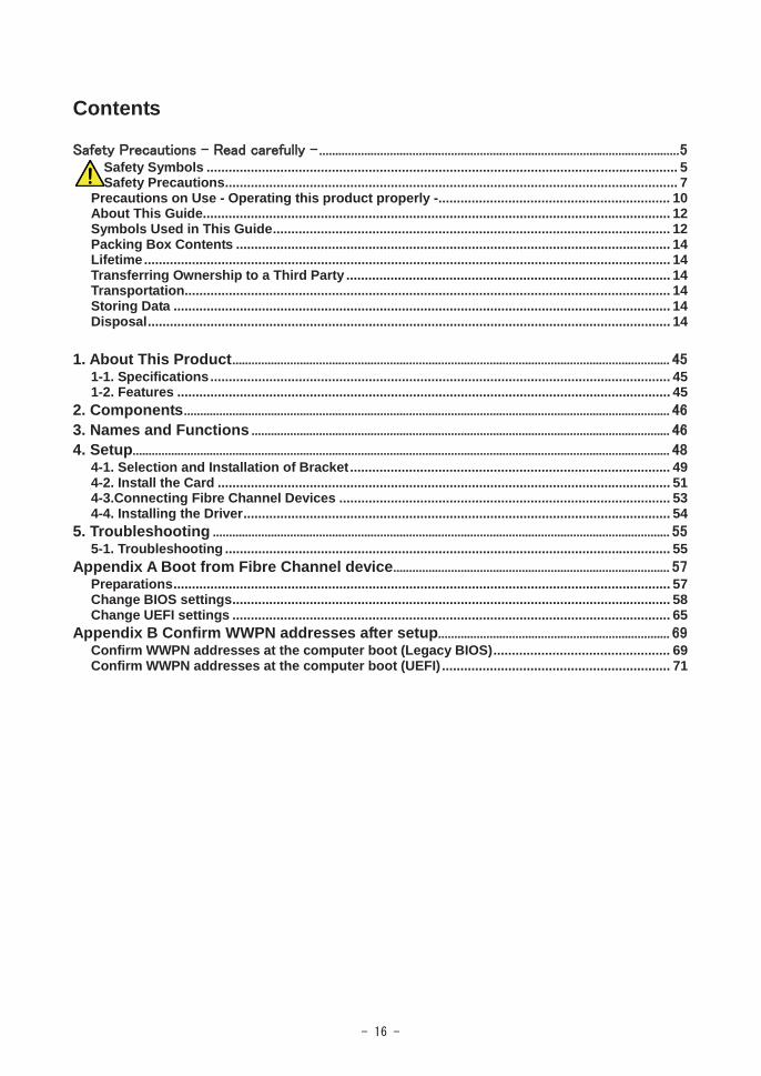
Contents
Safety Symbols ................................................................................................................................ 5 Safety Precautions........................................................................................................................... 7
Precautions on Use - Operating this product properly -............................................................... 10 About This Guide............................................................................................................................... 12 Symbols Used in This Guide............................................................................................................ 12 Packing Box Contents ...................................................................................................................... 14 Lifetime............................................................................................................................................... 14 Transferring Ownership to a Third Party ........................................................................................ 14 Transportation.................................................................................................................................... 14 Storing Data ....................................................................................................................................... 14 Disposal.............................................................................................................................................. 14
1. About This Product 1-1. Specifications............................................................................................................................. 45 1-2. Features ...................................................................................................................................... 45
2. Components 3. Names and Functions 4. Setup
4-1. Selection and Installation of Bracket....................................................................................... 49 4-2. Install the Card ........................................................................................................................... 51 4-3.Connecting Fibre Channel Devices .......................................................................................... 53 4-4. Installing the Driver.................................................................................................................... 54
5. Troubleshooting 5-1. Troubleshooting ......................................................................................................................... 55
Appendix A Boot from Fibre Channel device Preparations....................................................................................................................................... 57 Change BIOS settings....................................................................................................................... 58 Change UEFI settings ....................................................................................................................... 65
Appendix B Confirm WWPN addresses after setup Confirm WWPN addresses at the computer boot (Legacy BIOS)................................................ 69 Confirm WWPN addresses at the computer boot (UEFI) .............................................................. 71
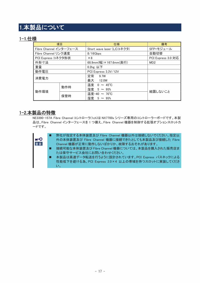
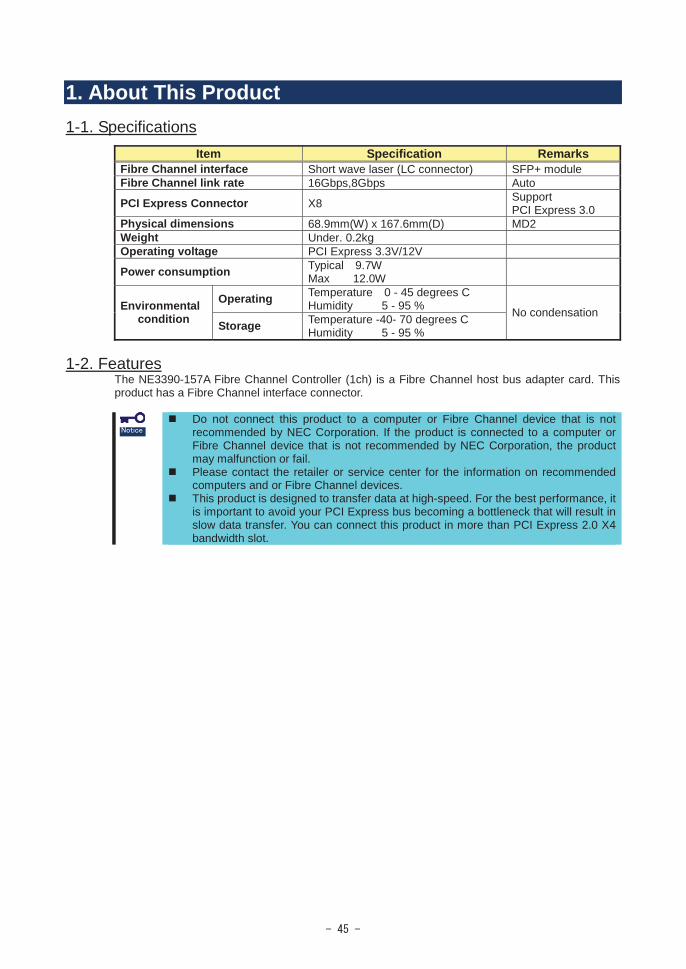
1. About This Product1-1. Specifications
Item Specification RemarksFibre Channel interface Short wave laser (LC connector) SFP+ moduleFibre Channel link rate 16Gbps,8Gbps Auto
PCI Express Connector X8 Support PCI Express 3.0
Physical dimensions 68.9mm(W) x 167.6mm(D) MD2Weight Under. 0.2kgOperating voltage PCI Express 3.3V/12V
Power consumption Typical 9.7WMax 12.0W
Environmentalcondition
Operating Temperature 0 - 45 degrees CHumidity 5 - 95 % No condensation
Storage Temperature -40- 70 degrees CHumidity 5 - 95 %
1-2. FeaturesThe NE3390-157A Fibre Channel Controller (1ch) is a Fibre Channel host bus adapter card. This product has a Fibre Channel interface connector.
Do not connect this product to a computer or Fibre Channel device that is not recommended by NEC Corporation. If the product is connected to a computer or Fibre Channel device that is not recommended by NEC Corporation, the product may malfunction or fail.Please contact the retailer or service center for the information on recommended computers and or Fibre Channel devices.This product is designed to transfer data at high-speed. For the best performance, it is important to avoid your PCI Express bus becoming a bottleneck that will result in slow data transfer. You can connect this product in more than PCI Express 2.0 X4bandwidth slot.
2. Components Please confirm that the following components are included with the product.If you find any of them are missing or damaged, please contact the retailer you bought the product from.
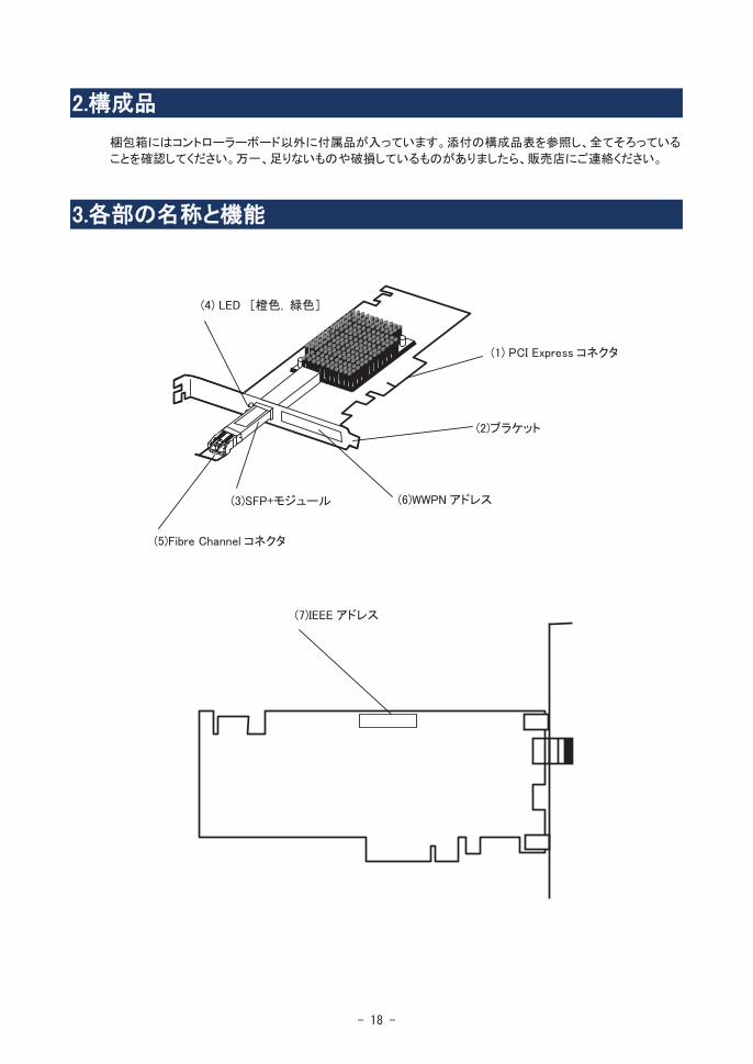
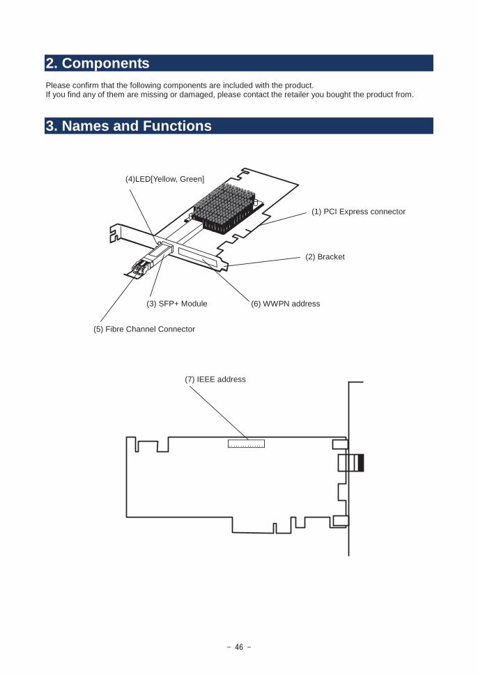
3. Names and Functions
(4)LED[Yellow, Green]
(1) PCI Express connector
(2) Bracket
(6) WWPN address(3) SFP+ Module
(5) Fibre Channel Connector
(7) IEEE address
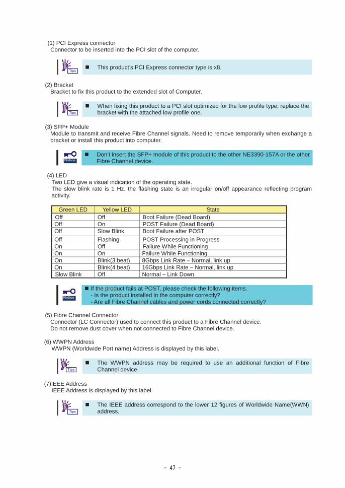
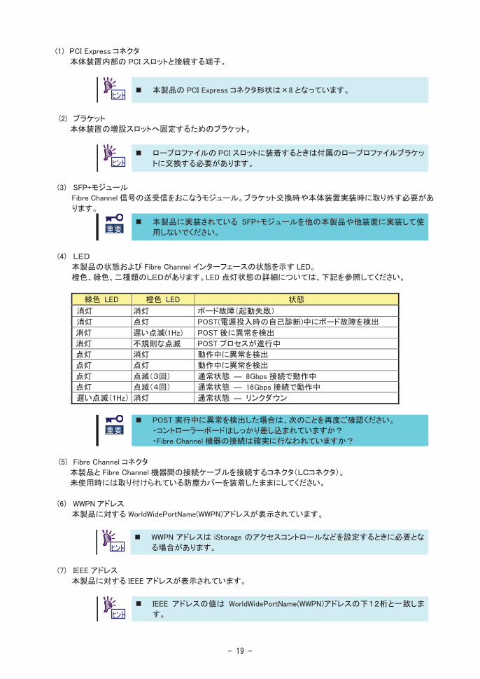
(1) PCI Express connectorConnector to be inserted into the PCI slot of the computer.
This product’s PCI Express connector type is x8.
(2) BracketBracket to fix this product to the extended slot of Computer.
When fixing this product to a PCI slot optimized for the low profile type, replace the bracket with the attached low profile one.
(3) SFP+ ModuleModule to transmit and receive Fibre Channel signals. Need to remove temporarily when exchange a bracket or install this product into computer.
Don’t insert the SFP+ module of this product to the other NE3390-157A or the other Fibre Channel device.
(4) LEDTwo LED give a visual indication of the operating state. The slow blink rate is 1 Hz. the flashing state is an irregular on/off appearance reflecting program activity.
Green LED Yellow LED StateOff Off Boot Failure (Dead Board)Off On POST Failure (Dead Board)Off Slow Blink Boot Failure after POSTOff Flashing POST Processing in ProgressOn Off Failure While FunctioningOn On Failure While FunctioningOn Blink(3 beat) 8Gbps Link Rate – Normal, link upOn Blink(4 beat) 16Gbps Link Rate – Normal, link upSlow Blink Off Normal – Link Down
If the product fails at POST, please check the following items.- Is the product installed in the computer correctly?- Are all Fibre Channel cables and power cords connected correctly?
(5) Fibre Channel ConnectorConnector (LC Connector) used to connect this product to a Fibre Channel device.Do not remove dust cover when not connected to Fibre Channel device.
(6) WWPN AddressWWPN (Worldwide Port name) Address is displayed by this label.
The WWPN address may be required to use an additional function of Fibre Channel device.
(7)IEEE AddressIEEE Address is displayed by this label.
The IEEE address correspond to the lower 12 figures of Worldwide Name(WWN)address.
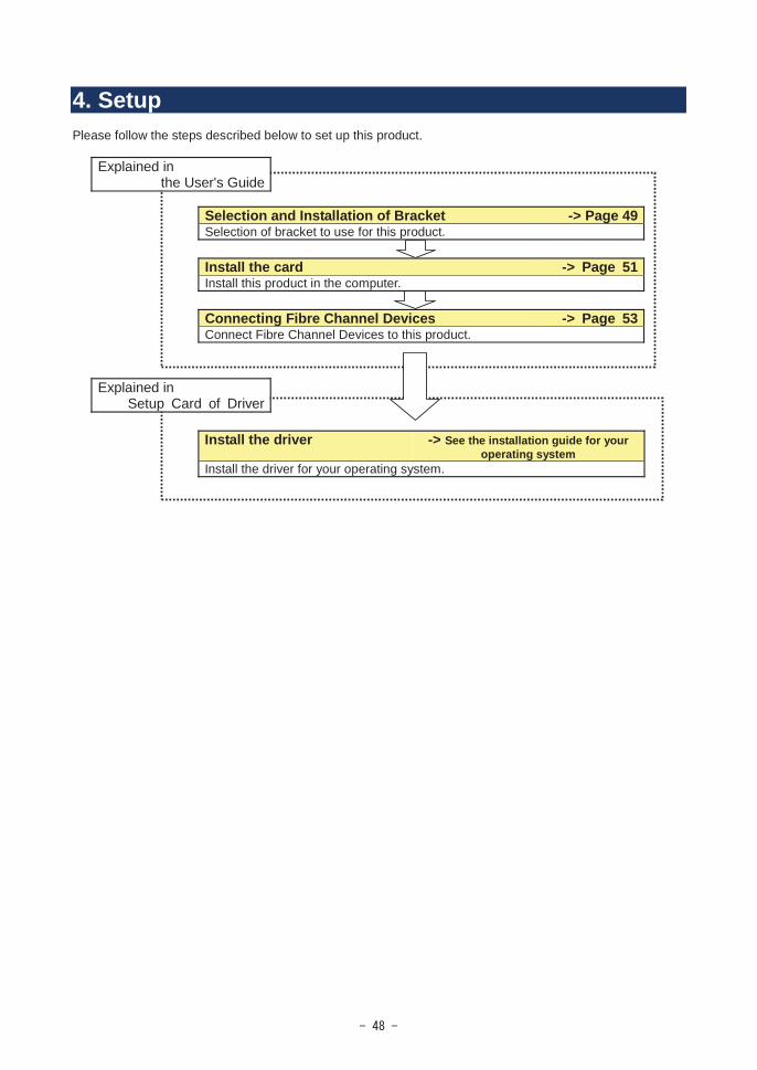
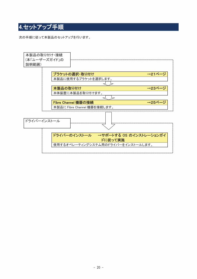
4. SetupPlease follow the steps described below to set up this product.
Explained inthe User's Guide
Selection and Installation of Bracket -> Page 49Selection of bracket to use for this product.
Install the card -> Page 51Install this product in the computer.
Connecting Fibre Channel Devices -> Page 53Connect Fibre Channel Devices to this product.
Explained inSetup Card of Driver
Install the driver -> See the installation guide for your operating system
Install the driver for your operating system.
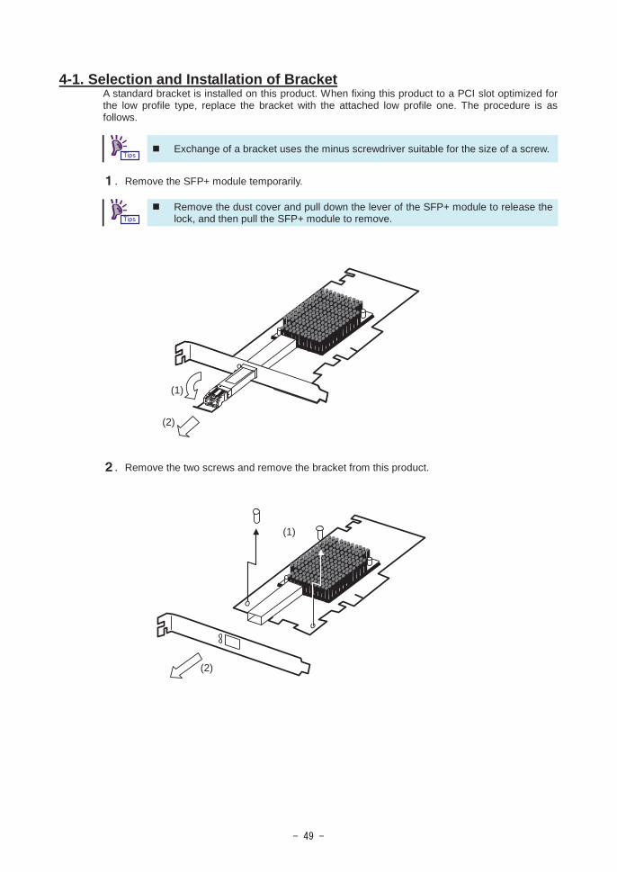
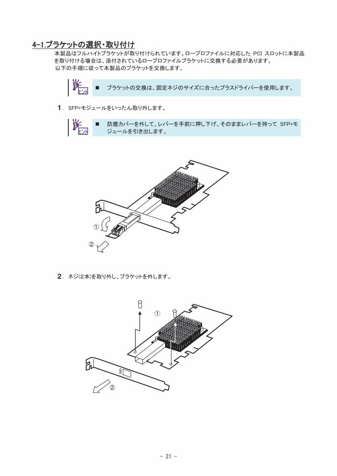
4-1. Selection and Installation of BracketA standard bracket is installed on this product. When fixing this product to a PCI slot optimized for the low profile type, replace the bracket with the attached low profile one. The procedure is as follows.
Exchange of a bracket uses the minus screwdriver suitable for the size of a screw.
. Remove the SFP+ module temporarily.
Remove the dust cover and pull down the lever of the SFP+ module to release the lock, and then pull the SFP+ module to remove.
. Remove the two screws and remove the bracket from this product.
(1)
(2)
(1)
(2)
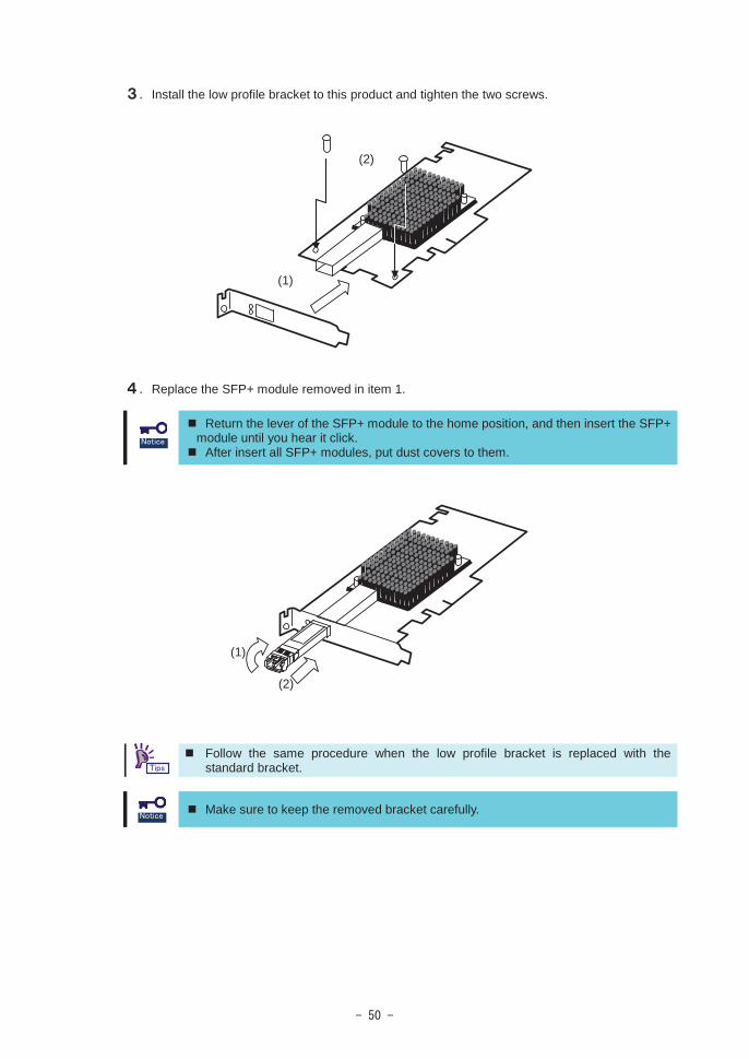
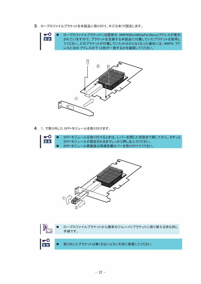
. Install the low profile bracket to this product and tighten the two screws.
. Replace the SFP+ module removed in item 1.
Return the lever of the SFP+ module to the home position, and then insert the SFP+ module until you hear it click.
After insert all SFP+ modules, put dust covers to them.
Follow the same procedure when the low profile bracket is replaced with the standard bracket.
Make sure to keep the removed bracket carefully.
(1)
(2)
(1)
(2)
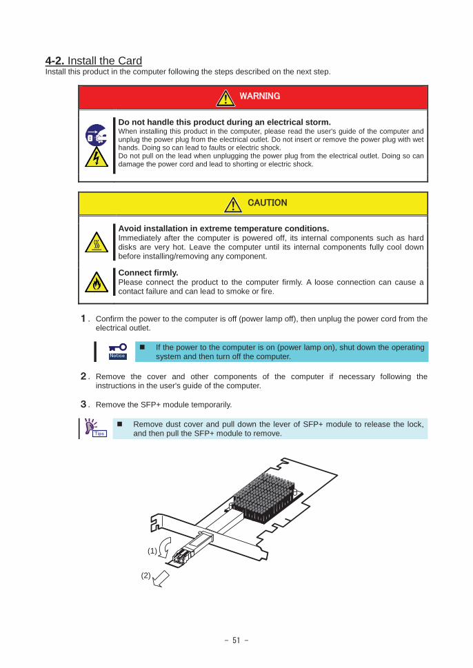
4-2. Install the CardInstall this product in the computer following the steps described on the next step.
Do not handle this product during an electrical storm.When installing this product in the computer, please read the user's guide of the computer and unplug the power plug from the electrical outlet. Do not insert or remove the power plug with wet hands. Doing so can lead to faults or electric shock.Do not pull on the lead when unplugging the power plug from the electrical outlet. Doing so can damage the power cord and lead to shorting or electric shock.
Avoid installation in extreme temperature conditions.Immediately after the computer is powered off, its internal components such as hard disks are very hot. Leave the computer until its internal components fully cool down before installing/removing any component.
Connect firmly.Please connect the product to the computer firmly. A loose connection can cause a contact failure and can lead to smoke or fire.
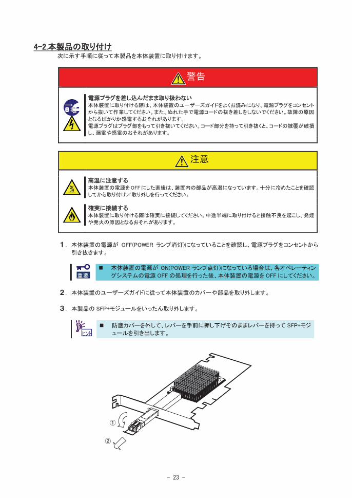
. Confirm the power to the computer is off (power lamp off), then unplug the power cord from the electrical outlet.
If the power to the computer is on (power lamp on), shut down the operating system and then turn off the computer.
. Remove the cover and other components of the computer if necessary following the instructions in the user's guide of the computer.
. Remove the SFP+ module temporarily.
Remove dust cover and pull down the lever of SFP+ module to release the lock,and then pull the SFP+ module to remove.
(1)
(2)
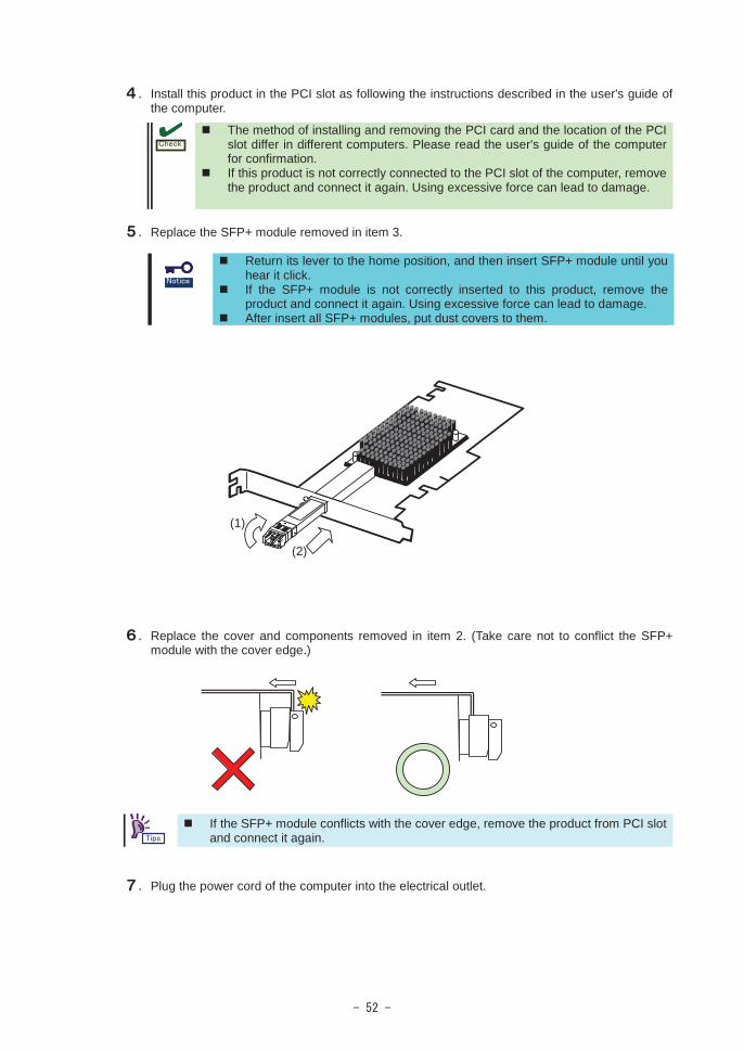
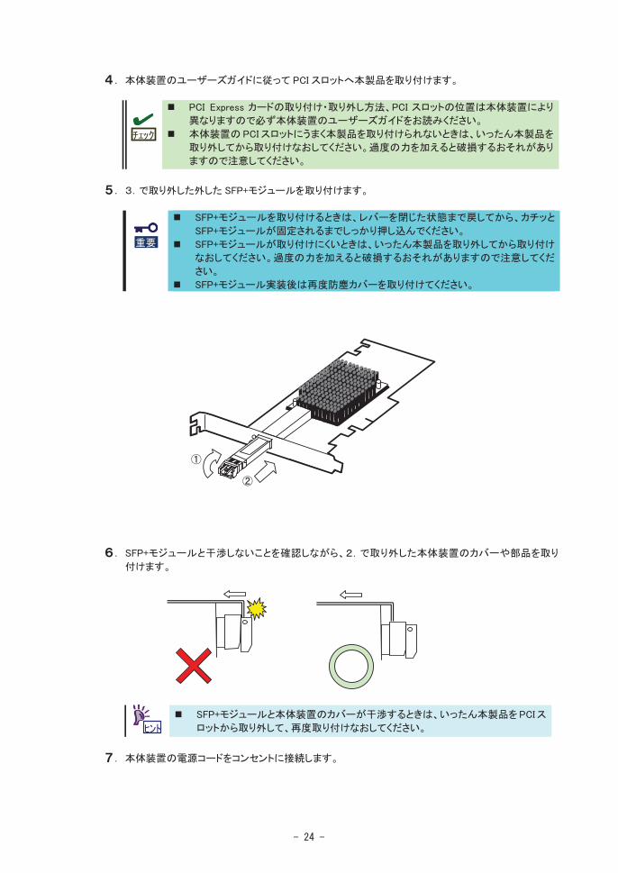
. Install this product in the PCI slot as following the instructions described in the user's guide of the computer.
The method of installing and removing the PCI card and the location of the PCI slot differ in different computers. Please read the user's guide of the computer for confirmation.If this product is not correctly connected to the PCI slot of the computer, remove the product and connect it again. Using excessive force can lead to damage.
. Replace the SFP+ module removed in item 3.
Return its lever to the home position, and then insert SFP+ module until you hear it click.If the SFP+ module is not correctly inserted to this product, remove the product and connect it again. Using excessive force can lead to damage.After insert all SFP+ modules, put dust covers to them.
. Replace the cover and components removed in item 2. (Take care not to conflict the SFP+ module with the cover edge.)
If the SFP+ module conflicts with the cover edge, remove the product from PCI slot and connect it again.
. Plug the power cord of the computer into the electrical outlet.
(1)
(2)

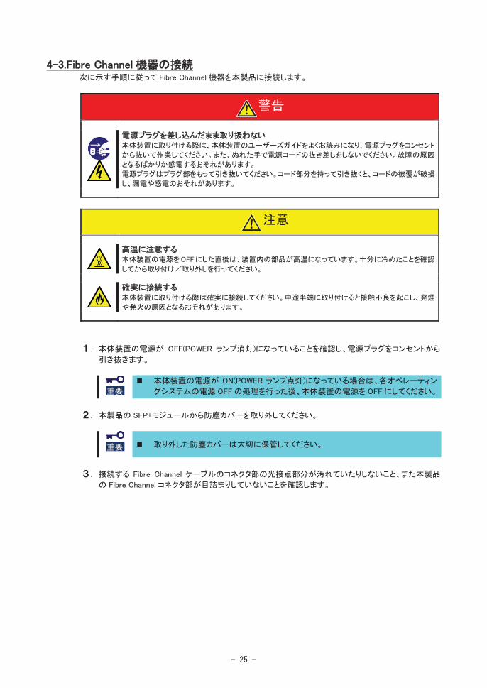
4-3.Connecting Fibre Channel DevicesInstall this product in the computer following the steps described on the next step.
Do not handle this product during an electrical storm.When installing this product in the computer, please read the user's guide of the computer and unplug the power plug from the electrical outlet. Do not insert or remove the power plug with wet hands. Doing so can lead to faults or electric shock.Do not pull on the lead when unplugging the power plug from the electrical outlet. Doing so can damage the power cord and lead to shorting or electric shock.
Avoid installation in extreme temperature conditions.Immediately after the computer is powered off, its internal components such as hard disks are very hot. Leave the computer until its internal components fully cool down before installing/removing any component.
Connect firmly.Please connect the product to the computer firmly. A loose connection can cause a contact failure and can lead to smoke or fire.
1. Confirm the power to the computer is off (power lamp off), then unplug the power cord from the electrical outlet.
If the power to the computer is on (power lamp on), shut down the operating system and then turn off the computer.
2. Remove the dust cover from Fibre the SFP+ module of the product.
Make sure to keep the dust cover carefully.
3. Confirm that the edge of the Fibre Channel cable and the holes of the connector of this product are clear.

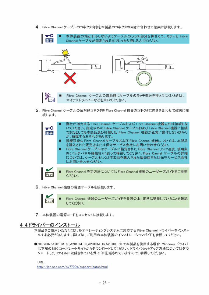
4. Mate the cable connector and the connector of this product firmly in the correct direction.
Push the latch of the Fibre Channel cable to avoid conflict with the computer flame and then insert the Fibre Channel cable until you hear it click.
If it is difficult to push the latch of the Fibre Channel cable when connect or remove the Fibre Channel cable, use a flathead screwdriver to push the latch.
5. Mate the other end of the cable connector and the Fibre Channel device firmly in the correct direction.
Do not connect this product to a computer or Fibre Channel device that is not recommended by NEC Corporation. If the product is connected to a computer or Fibre Channel device that is not recommended by NEC Corporation, the product may malfunction or fail.Do not use Fibre Channel cable that is not recommended by NEC Corporation. If the product is connected to Fibre Channel device by Fibre Channel cable that is not recommended by NEC Corporation, the product may malfunction or fail.Use Fibre Channel cables under conditions that conform to the cable specification (length between device, Fibre Channel data rate and so on).Please contact the retailer or service center for the information on recommended computers, Fibre Channel devices, or Fibre Channel cables.
Please refer to the user's guide of the product for information on how to setting Fibre Channel device.
6. Plug the power cord of the Fibre Channel device into the electrical outlet. For detailed information, please refer to the user's guide of the Fibre Channel device.
7. Plug the power cord of the computer into the electrical outlet.
4-4. Installing the Driver
To use this product, the appropriate Fibre Channel driver for your operating system must be installed. For detailed information, refer to the installation guide for the computer.
The Windows driver for Express5800/A1040b,A2040b,A2020b,A2010b is published on NEC web site.Also an installation guide of this product includes in the files on NEC web site.To get the driver and the installation guide, access to the NEC web site.
URL:http://www.58support.nec.co.jp/global/download/index.html
5. Troubleshooting5-1. Troubleshooting
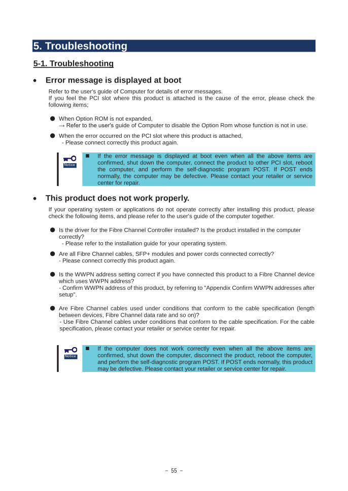
Error message is displayed at bootRefer to the user's guide of Computer for details of error messages.If you feel the PCI slot where this product is attached is the cause of the error, please check the following items;
When Option ROM is not expanded,guide of Computer to disable the Option Rom whose function is not in use.
When the error occurred on the PCI slot where this product is attached,- Please connect correctly this product again.
If the error message is displayed at boot even when all the above items are confirmed, shut down the computer, connect the product to other PCI slot, reboot the computer, and perform the self-diagnostic program POST. If POST ends normally, the computer may be defective. Please contact your retailer or service center for repair.
This product does not work properly. If your operating system or applications do not operate correctly after installing this product, please check the following items, and please refer to the user's guide of the computer together.
Is the driver for the Fibre Channel Controller installed? Is the product installed in the computer correctly?- Please refer to the installation guide for your operating system.
Are all Fibre Channel cables, SFP+ modules and power cords connected correctly?- Please connect correctly this product again.
Is the WWPN address setting correct if you have connected this product to a Fibre Channel device which uses WWPN address?- Confirm WWPN address of this product, by referring to "Appendix Confirm WWPN addresses after setup".
Are Fibre Channel cables used under conditions that conform to the cable specification (lengthbetween devices, Fibre Channel data rate and so on)?- Use Fibre Channel cables under conditions that conform to the cable specification. For the cable specification, please contact your retailer or service center for repair.
If the computer does not work correctly even when all the above items are confirmed, shut down the computer, disconnect the product, reboot the computer, and perform the self-diagnostic program POST. If POST ends normally, this product may be defective. Please contact your retailer or service center for repair.

Fibre Channel Device go missingConfirm the followings if the Fibre Channel device which was in use and connected to this product is not detected by the operating system or is inaccessible after rebooting Computer. Also, refer to the User’s Guide that came with the Fibre Channel device, and other guides of applications you use.
<For Windows OS>Select [Administrative Tools] - [Computer Management] - [Device Manager], and confirm that you can see the Fibre Channel device under [Disk Drive].- If you cannot see it, try either of the followings.
(1) Select [Computer Management] - [Disk Management]. If you can see the drive letter assigned to the Fibre Channel device, close the Computer Management, and try to access again.
(2) Reboot Computer if possible, and try to access again.
<For All OS>Is the Fibre Channel where this product is connected working properly?- Refer to the guides of your device, and confirm that it is working properly.
If the Fibre Channel device is not detected even when all the above items are confirmed. Please contact your retailer or service center for repair.
No response in UEFI menuConfirm the followings if no response in UEFI menu.
If select [Back to UEFI Device Manager and RECONNECT DEVICES] and press <Enter>.- Press <Enter>, press <Alt>, <Ctrl> and <Del> keys simultaneously to reboot the computer.
If select [Scan for Fibre Devices] and press <Enter>.- Confirm the Fibre Channel devices are working properly and wait a minutes.
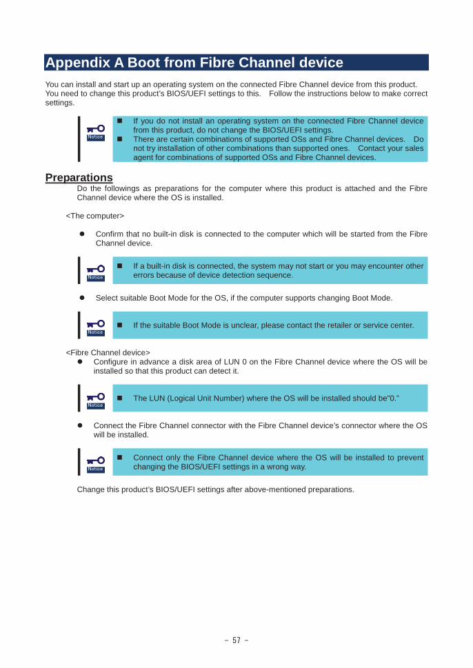
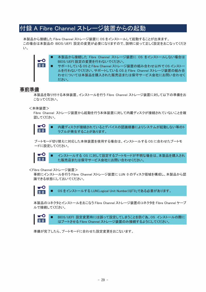
Appendix A Boot from Fibre Channel deviceYou can install and start up an operating system on the connected Fibre Channel device from this product. You need to change this product’s BIOS/UEFI settings to this. Follow the instructions below to make correctsettings.
If you do not install an operating system on the connected Fibre Channel device from this product, do not change the BIOS/UEFI settings.There are certain combinations of supported OSs and Fibre Channel devices. Do not try installation of other combinations than supported ones. Contact your sales agent for combinations of supported OSs and Fibre Channel devices.
PreparationsDo the followings as preparations for the computer where this product is attached and the Fibre Channel device where the OS is installed.
<The computer>
Confirm that no built-in disk is connected to the computer which will be started from the Fibre Channel device.
If a built-in disk is connected, the system may not start or you may encounter other errors because of device detection sequence.
Select suitable Boot Mode for the OS, if the computer supports changing Boot Mode.
If the suitable Boot Mode is unclear, please contact the retailer or service center.
<Fibre Channel device>Configure in advance a disk area of LUN 0 on the Fibre Channel device where the OS will be installed so that this product can detect it.
The LUN (Logical Unit Number) where the OS will be installed should be”0.”
Connect the Fibre Channel connector with the Fibre Channel device’s connector where the OS will be installed.
Connect only the Fibre Channel device where the OS will be installed to prevent changing the BIOS/UEFI settings in a wrong way.
Change this product’s BIOS/UEFI settings after above-mentioned preparations.
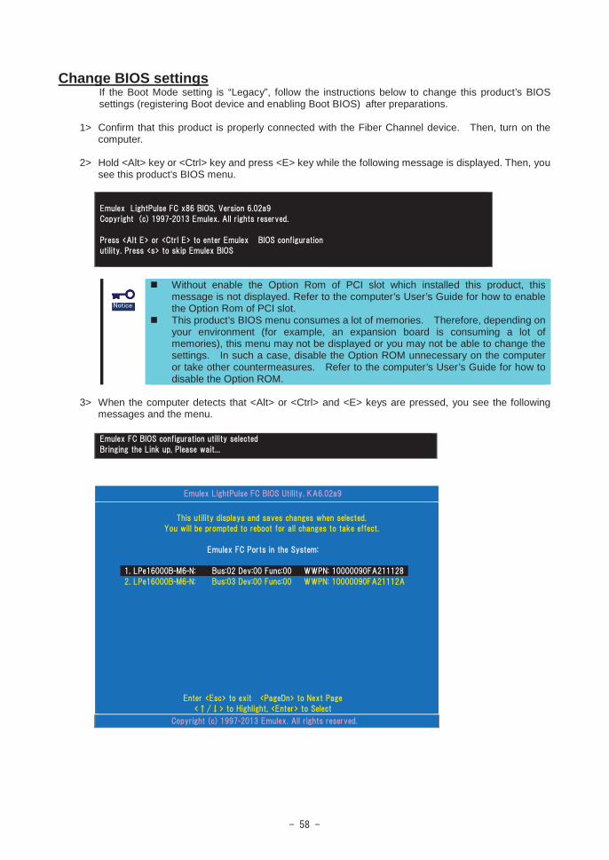
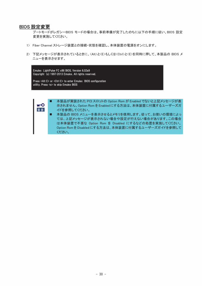
Change BIOS settingsIf the Boot Mode setting is “Legacy”, follow the instructions below to change this product’s BIOS settings (registering Boot device and enabling Boot BIOS) after preparations.
1> Confirm that this product is properly connected with the Fiber Channel device. Then, turn on the computer.
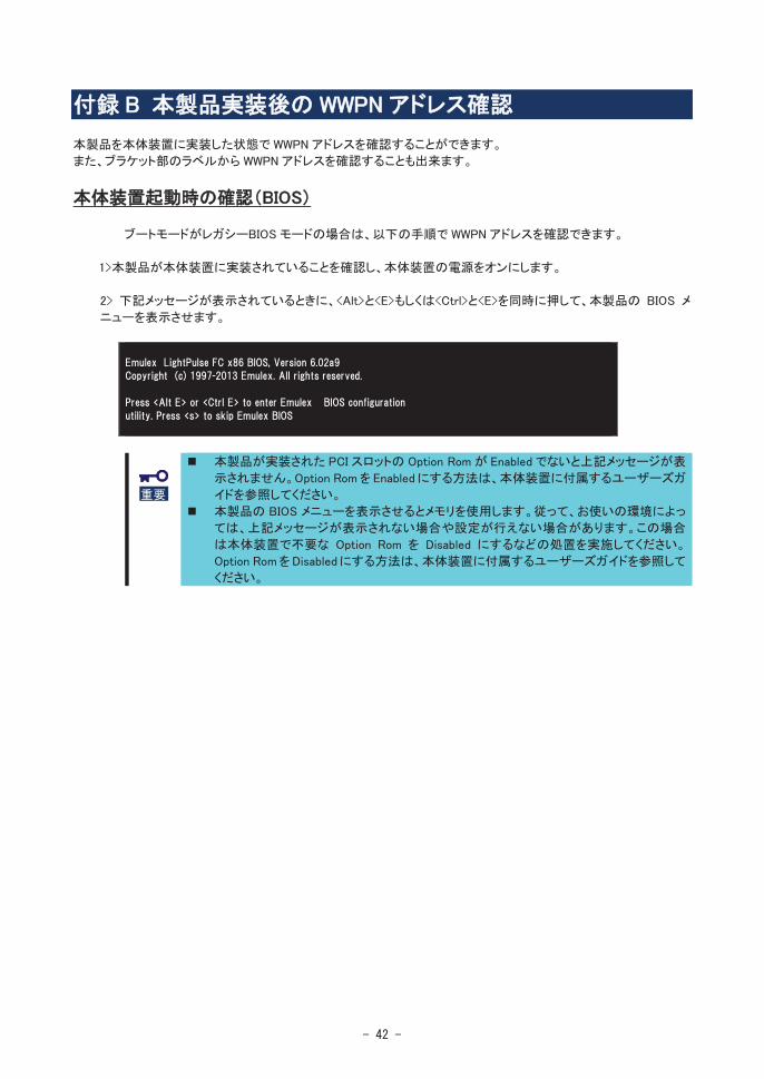
2> Hold <Alt> key or <Ctrl> key and press <E> key while the following message is displayed. Then, you see this product’s BIOS menu.
Without enable the Option Rom of PCI slot which installed this product, this message is not displayed. Refer to the computer’s User’s Guide for how to enable the Option Rom of PCI slot.This product’s BIOS menu consumes a lot of memories. Therefore, depending on your environment (for example, an expansion board is consuming a lot of memories), this menu may not be displayed or you may not be able to change the settings. In such a case, disable the Option ROM unnecessary on the computeror take other countermeasures. Refer to the computer’s User’s Guide for how to disable the Option ROM.
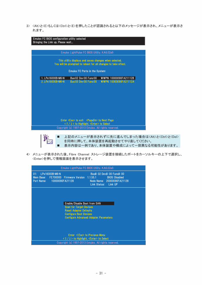
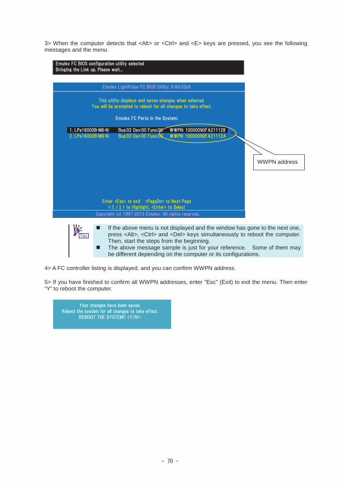
3> When the computer detects that <Alt> or <Ctrl> and <E> keys are pressed, you see the following messages and the menu.
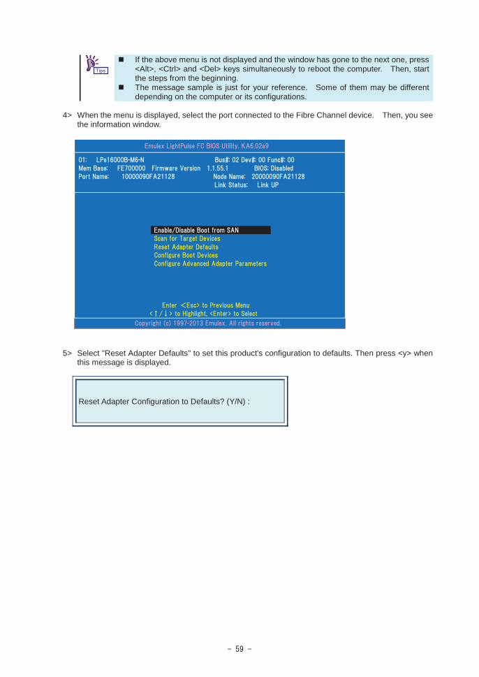
If the above menu is not displayed and the window has gone to the next one, press <Alt>, <Ctrl> and <Del> keys simultaneously to reboot the computer. Then, start the steps from the beginning.The message sample is just for your reference. Some of them may be different depending on the computer or its configurations.
4> When the menu is displayed, select the port connected to the Fibre Channel device. Then, you see the information window.
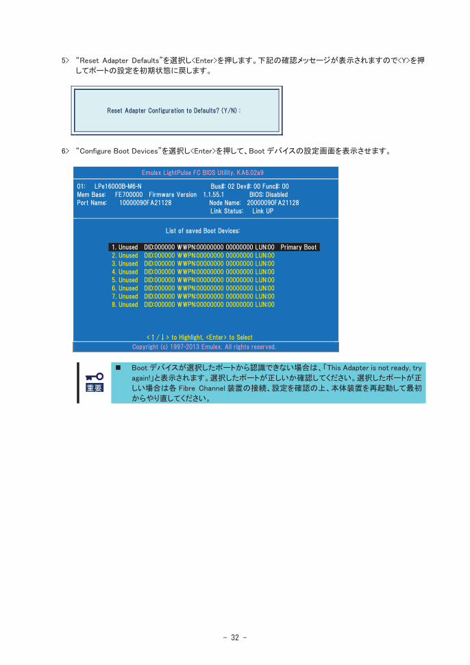
5> Select "Reset Adapter Defaults" to set this product's configuration to defaults. Then press <y> when this message is displayed.
Reset Adapter Configuration to Defaults? (Y/N) :
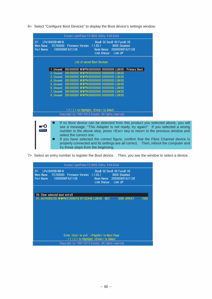
6> Select “Configure Boot Devices” to display the Boot device’s settings window.
If no Boot device can be detected from this product you selected above, you will see a message, “This Adapter is not ready, try again!” If you selected a wrong number in the above step, press <Esc> key to return to the previous window and select the correct one.If you have selected the correct figure, confirm that the Fibre Channel device is properly connected and its settings are all correct. Then, reboot the computer andtry these steps from the beginning.
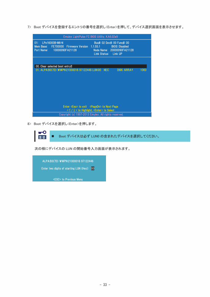
7> Select an entry number to register the Boot device. Then, you see the window to select a device.
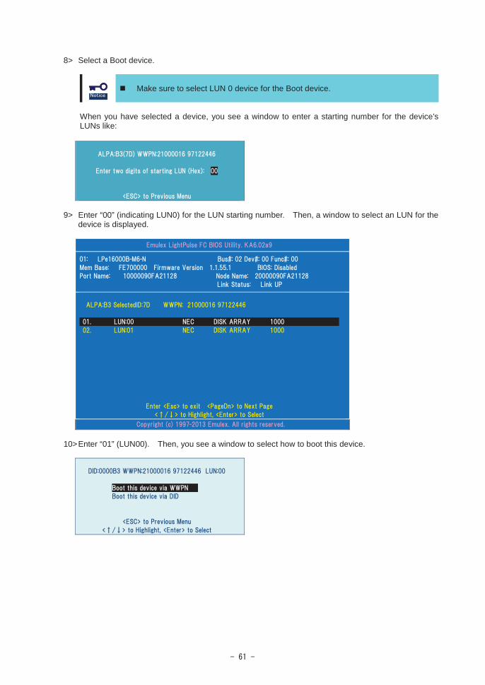
8> Select a Boot device.
Make sure to select LUN 0 device for the Boot device.
When you have selected a device, you see a window to enter a starting number for the device’s LUNs like:
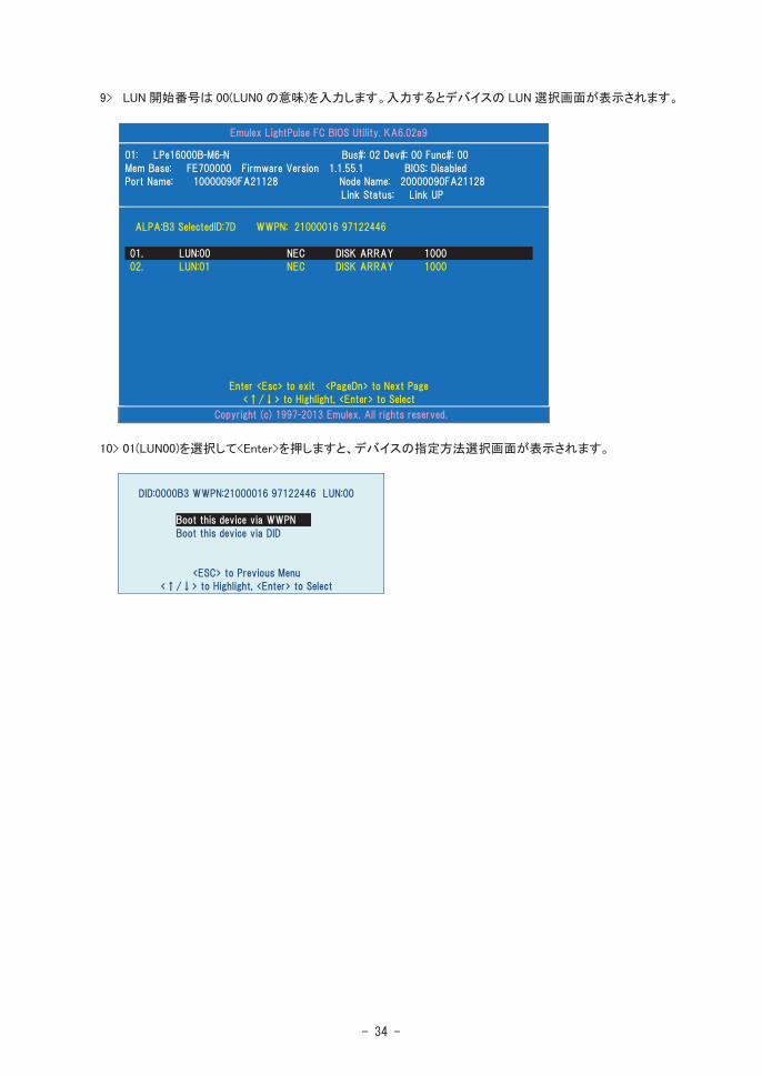
9> Enter “00” (indicating LUN0) for the LUN starting number. Then, a window to select an LUN for the device is displayed.
10>Enter “01” (LUN00). Then, you see a window to select how to boot this device.
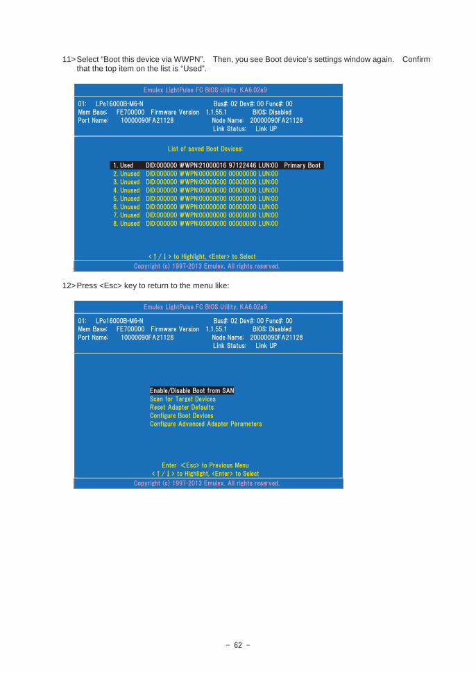
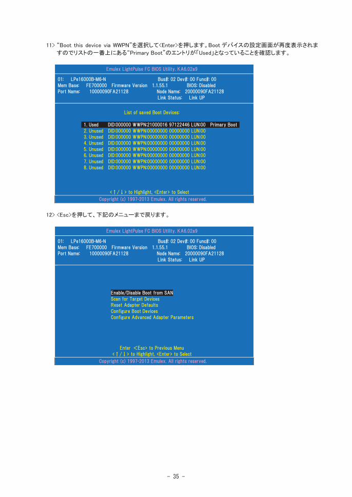
11>Select “Boot this device via WWPN”. Then, you see Boot device’s settings window again. Confirm that the top item on the list is “Used”.
12>Press <Esc> key to return to the menu like:
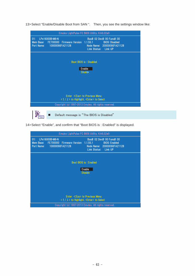
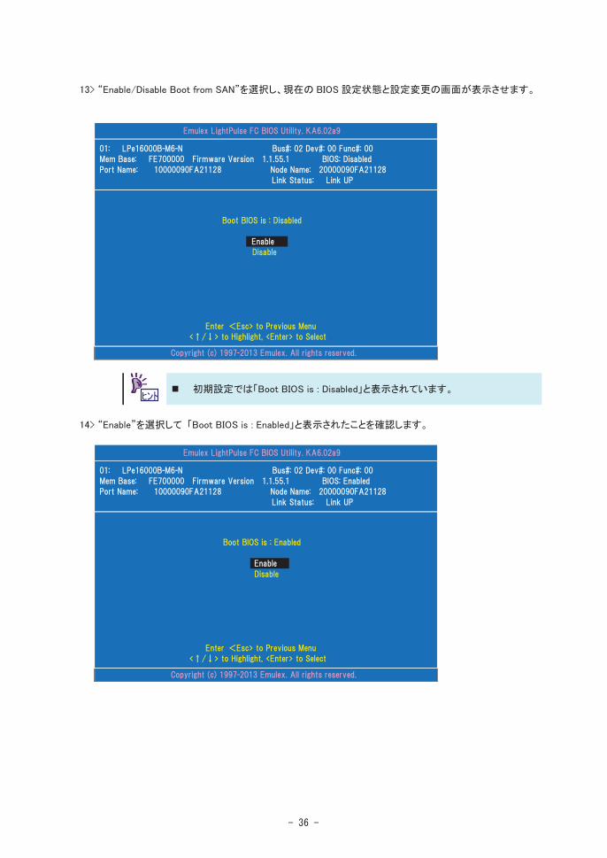
13>Select “Enable/Disable Boot from SAN “. Then, you see the settings window like:
14>Select “Enable”, and confirm that “Boot BIOS is : Enabled” is displayed.

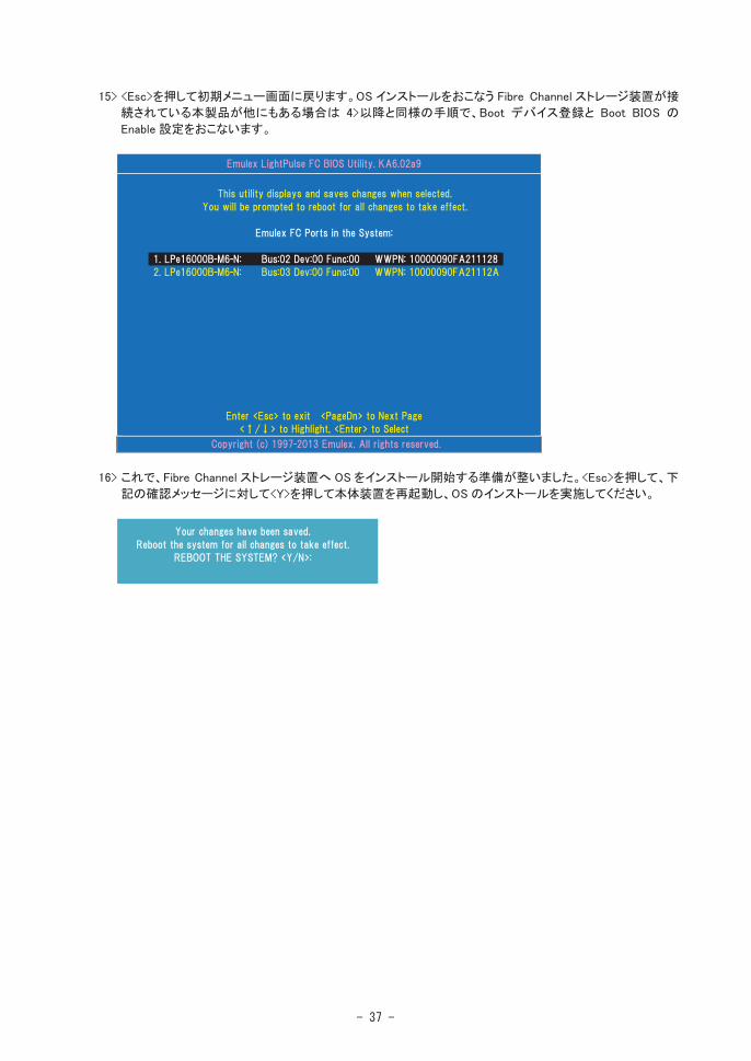
15>If any other ports of this product are connected to the Fibre Channel boot device, Press <Esc> key to return to the adapter list and setting ports by the same steps from 4>.
16>Now, you have made settings to start installing an operating system on your Fibre Channel device. Press <Esc> key to exit the menu. Then press <y> when this message is displayed, to reboot the computer and start installation.

Change UEFI settingsIf the Boot Mode setting is “UEFI”, follow the instructions below to change this product’s UEFIsettings (registering Boot device and enabling Boot) after preparations.
1> Turn on the computer which this product is installed.
2> Set "Enabled" the Option Rom of PCI slot which installed this product connected to the Fibre Channel device, then save changes and reboot the computer. Refer to the computer's User's Guide for how to enable the Option Rom of PCI slot.
3> Select “UEFI Driver Configuration” submenu in the SETUP utility of the computer. Refer to the computer's User's Guide for how to use the SETUP utility.
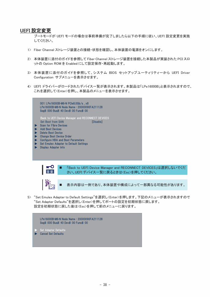
4> Select this product (LPe16000B) from the list of devices which UEFI driver loaded. Then, you see the settings menu like:
Do not select “Back to UEFI Device Manager and RECONNECT DEVICES”. Press <Esc>, when you want to return to the adapter list.
The menu sample is just for your reference. Some of them may be different depending on the computer or its configurations.
5> Select "Set Emulex Adapter to Default Settings" and press <Enter> to set this product's configuration to defaults. Select “Set Adapter Defaults” and press <Enter> when this menu is displayed.Then press <Esc> to return to main menu.

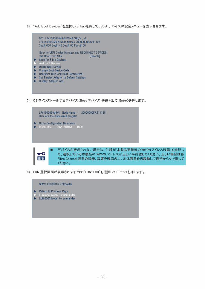
6> Select “Add Boot Devices” and press <Enter>.
7> A screen appears displaying the discovered targets. Then select the Boot device and press <Enter>.
If no Boot Device can be discovered from this product, confirm the WWPN which you selected. Refer “Appendix B Confirm WWPN addresses after setup” to find this product’s WWPN. If you have selected the correct WWPN, confirm that the Fibre Channel device is properly connected and its settings are all correct. Then, reboot the computer and try these steps from the beginning.
8> A list of bootable LUNs is displayed. Then select “LUN:0000” and press <Enter>.

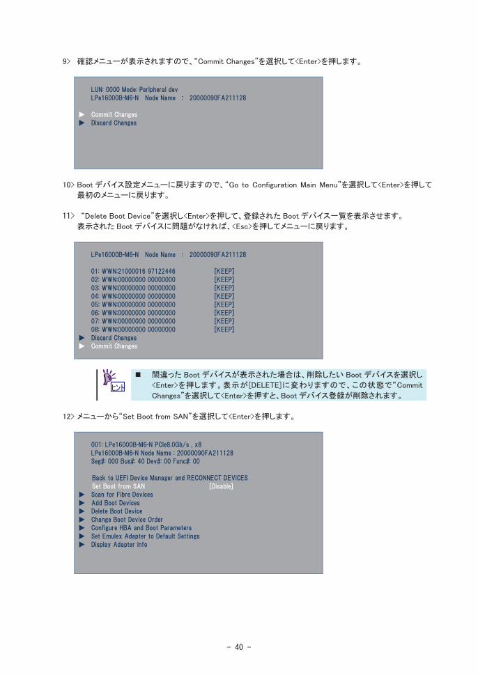
9> Select “Commit Changes” and press <Enter> when this menu is displayed.
10>When displaying list of the discovered targets again, select “Go to configuration Main Menu” andpress <Enter> to return to main menu.
11>Select “Delete Boot Device” and press <Enter> to display the registered Boot Devices list.If there is no problem in this list, press <Esc> to return to main menu.
If there are any wrong Boot Devices, select the wrong device and press <Enter>. The device appears with [DELETE], and then you select “Commit Changes” and press <Enter> to delete wrong Boot Devises.
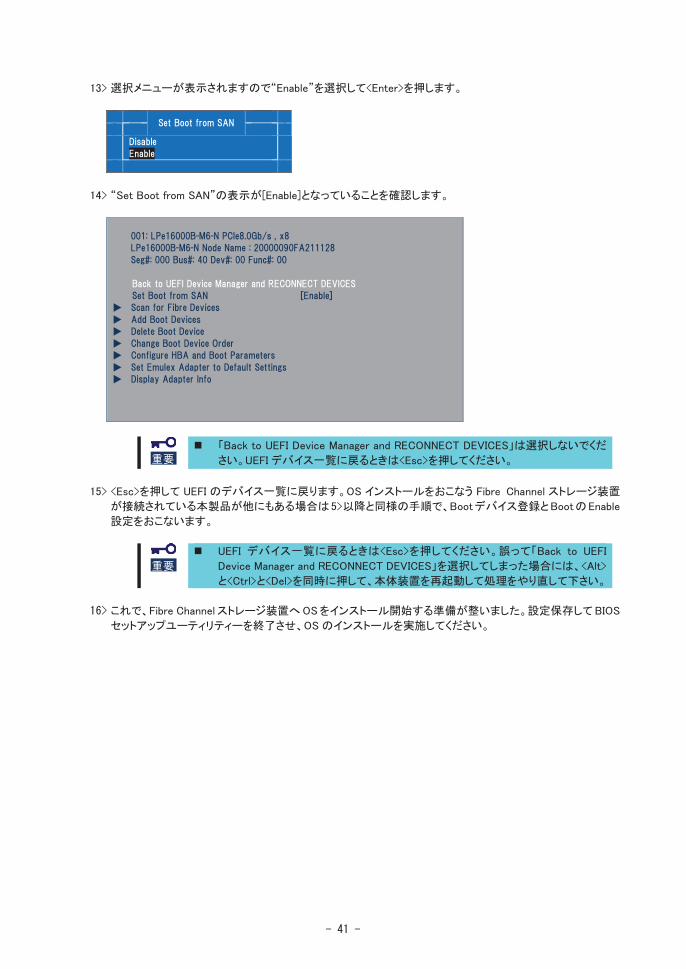
12>Select “Set Boot from SAN” and press <Enter> from main menu.

13>A Disable/Enable menu appears. Select “Enable” and press <Enter>.
14>Confirm that the setting of “Set Boot from SAN” is [Enable].
Do not select “Back to UEFI Device Manager and RECONNECT DEVICES”. Press <Esc>, when you want to return to the adapter list.
15>If any other ports of this product are connected to the Fibre Channel boot device, Press <Esc> key to return to the adapter list and setting ports by the same steps from 5>.
Press <Esc> to return to the adapter list. If select “Back to UEFI Device Manager and RECONNECT DEVICES” and press <Enter>, press <Alt>, <Ctrl> and <Del> keys simultaneously to reboot the computer. Then, start the steps from the beginning.
16>Now, you have made settings to start installing an operating system on your Fibre Channel device. Save changes and exit the STEUP utility of the computer, and start installation.

Appendix B Confirm WWPN addresses after setupYou can confirm WWPN addresses of this product after install this product into the computer by latter procedures or the WWPN label on the bracket.
Confirm WWPN addresses at the computer boot (Legacy BIOS)If the Boot Mode setting is "Legacy", follow the instructions below to confirm WWPN addresses.
1> Confirm that this product is properly installed. Then, turn on the computer.
2> Hold <Alt> key or <Ctrl> key and press <E> key while the following message is displayed. Then, you see this product’s BIOS menu.
Without enable the Option Rom of PCI slot which installed this product, this message is not displayed. Refer to the computer’s User’s Guide for how to enable the Option Rom of PCI slot.This product’s BIOS menu consumes a lot of memories. Therefore, depending on your environment (for example, an expansion board is consuming a lot of memories), this message may not be displayed or you may not be able to change the settings. In such a case, disable the Option Rom unnecessary on computer or take other countermeasures. Refer to the computer’s User’s Guide for how to disable the Option Rom.
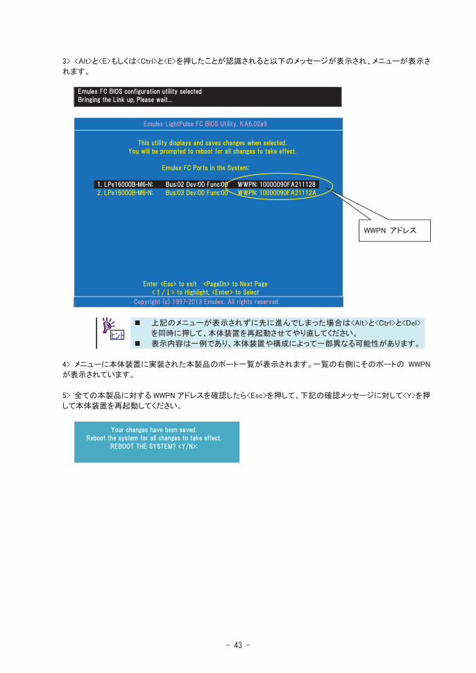
3> When the computer detects that <Alt> or <Ctrl> and <E> keys are pressed, you see the following messages and the menu.
If the above menu is not displayed and the window has gone to the next one, press <Alt>, <Ctrl> and <Del> keys simultaneously to reboot the computer.Then, start the steps from the beginning.The above message sample is just for your reference. Some of them may be different depending on the computer or its configurations.
4> A FC controller listing is displayed, and you can confirm WWPN address.
5> If you have finished to confirm all WWPN addresses, enter "Esc" (Exit) to exit the menu. Then enter “Y” to reboot the computer.
WWPN address
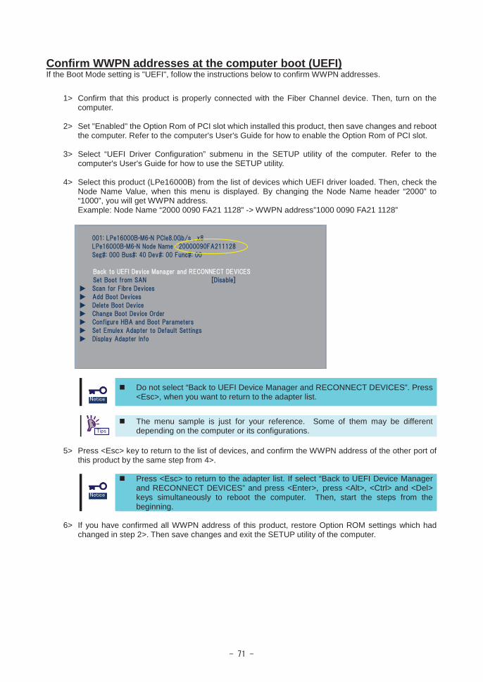
Confirm WWPN addresses at the computer boot (UEFI)If the Boot Mode setting is "UEFI", follow the instructions below to confirm WWPN addresses.
1> Confirm that this product is properly connected with the Fiber Channel device. Then, turn on the computer.
2> Set "Enabled" the Option Rom of PCI slot which installed this product, then save changes and reboot the computer. Refer to the computer's User's Guide for how to enable the Option Rom of PCI slot.
3> Select “UEFI Driver Configuration” submenu in the SETUP utility of the computer. Refer to the computer's User's Guide for how to use the SETUP utility.
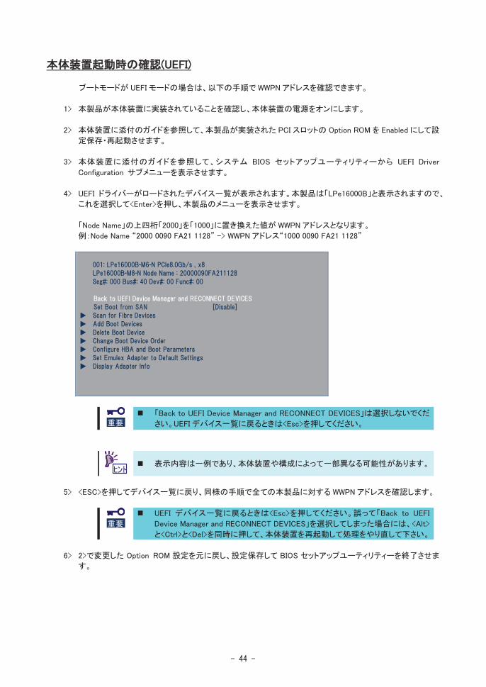
4> Select this product (LPe16000B) from the list of devices which UEFI driver loaded. Then, check theNode Name Value, when this menu is displayed. By changing the Node Name header “2000” to “1000”, you will get WWPN address.Example: Node Name “2000 0090 FA21 1128” -> WWPN address”1000 0090 FA21 1128”
Do not select “Back to UEFI Device Manager and RECONNECT DEVICES”. Press <Esc>, when you want to return to the adapter list.
The menu sample is just for your reference. Some of them may be different depending on the computer or its configurations.
5> Press <Esc> key to return to the list of devices, and confirm the WWPN address of the other port of this product by the same step from 4>.
Press <Esc> to return to the adapter list. If select “Back to UEFI Device Manager and RECONNECT DEVICES” and press <Enter>, press <Alt>, <Ctrl> and <Del> keys simultaneously to reboot the computer. Then, start the steps from the beginning.
6> If you have confirmed all WWPN address of this product, restore Option ROM settings which had changed in step 2>. Then save changes and exit the SETUP utility of the computer.

©
This guide is made with recycled paper.
’