Embed Size (px)
Citation preview

TRITA-MET 113 ISSN 1403-493X ISRN KTH-MET/R-01/113-SE ISBN 91-7283-073-5
Growth and Removal of Inclusions During Ladle Stirring
MATS SÖDER
LICENTIATE THESIS
STOCKHOLM DEPARTMENT OF MATERIALS SCIENCE AND ENGINEERING MARCH 2001 DIVISION OF METALLURGY ROYAL INSTITUTE OF TECHNOLOGY SE – 100 44 STOCKHOLM
Growth and Removal of Inclusions During Ladle Stirring
Mats Söder
Licentiate Thesis
Department of Materials Science and Engineering
Division of Metallurgy
Royal Institute of Technology
SE-100 44 Stockholm
Sweden
Akademisk avhandling som med tillstånd av Kungliga Tekniska Högskolan i Stockholm,
framlägges för offentlig granskning för avläggande av teknisk licentiatexamen, fredagen den 6 april
2001 kl. 14.00 i B3, Brinellvägen 23, Kungliga Tekniska Högskolan, Stockholm.
ISSN 1403-493X
ISRN KTH-MET/R-01/113-SE
ISBN 91-7283-073-5

3
ABSTRACT The growth and removal of inclusions in stirred ladles has been studied. First, the importance of different growth mechanisms suggested in the literature were studied. Simulation results from a fundamental model of an induction-stirred ladle have been used as input in the calculations. Based on the growth calculations it was concluded that four of the growth mechanisms need not to be considered since they contribute so little: i) diffusion of oxygen and aluminum to the inclusion surface, ii) diffusion coalescence, iii) Brown motion collision, and iv) laminar shear collision. The major contributor to inclusion growth is turbulent collision. Growth due to Stoke's collisions is also somewhat important if large differences among inclusion sizes exist. Growth of inclusions in gas stirred ladles was studied using a similar approach as the one for induction stirred ladles, but with use of simulation results from a fundamental mathematical model of a gas-stirred ladle. Similarly to what was found in the case of induction stirring, it was found that turbulent collisions and Stokes collisions appeared to be the major mechanisms for inclusion growth. The contribution of laminar shear collisions to growth was deemed negligible compared to that of turbulent collisions. For the gas stirred ladle different removal mechanisms were also studied, based on input data from a mathematical model of a gas-stirred ladle. It was found that different models suggested to predict the inclusion removal due to bubble flotation gave very different results. Also, all models assumed a spherical shape of the gas bubbles, which was found to be less realistic. Therefore, a new model for inclusion removal by spherical cap bubble flotation was developed. In the new calculations, the most important mechanisms of inclusion removal were found to be removal to the top slag and removal by bubble flotation, assuming spherical-cap bubbles and plane contact. When the bubbles were assumed to be spherical, resulting removal rates were lower than when they were assumed to be spherical caps. Based on these results it is concluded that more research is needed to obtain a better understanding of the importance of bubble flotation on inclusion removal. Experiments are clearly needed to determine which model concepts produce predictions in best agreement with corresponding data from actual steelmaking processes.

4
ACKNOWLEDGEMENT The author would like to gratefully acknowledge the Swedish Steel Producers Association and the comity JK2347 for financing the project. A special thanks goes to all the comity members. For the supervising my dear professor Pär Jönsson is gratefully acknowledged. A thanks to my friends at MEFOS, professor Lage Jonsson, dr. Jonas Alexis and dr. Dong-Yuan Sheng for their kind help with CFD models and reading manuscripts. To all my colleagues at the department of Metallurgy at the Royal Institute of Technology I give special thanks for creating an inspiring environment. Your friendship is very valuable to me. Finally, I wish to put forward my sincere gratitude to my precious wife, Pernilla, for all the support and understanding.
5
SUPPLEMENTS This thesis is based on the following supplements: Supplement 1: Söder M, Jönsson P and Alexis J: Most Relevant Mechanisms of
Inclusion Growth in an Induction-Stirred Ladle. Submitted for publication to Scandinavian Journal of Metallurgy, March 2001.
Supplement 2: Sheng D-Y, Söder M, Jönsson P, and Jonsson L: Modeling Micro-
Inclusion Growth and Separation in Gas-Stirred Ladles. Accepted for publication in Scandinavian Journal of Metallurgy.
Supplement 3: Söder M, Jönsson P and Jonsson L: Growth and Removal of Inclusions
in Gas Stirred Ladles. Submitted for publication to Steel Research, March 2001.
TABLE OF CONTENTS
1. BACKGROUND ... . . . . . . . . . . . . . . . . . . . . . . . . . . . . . . . . . . . . . . . . . . . . . . . . . . . . . . . . . . . . . . . . . . . . . . . . . . . . . . 1
2. THEORY FOR INCLUSION GROWTH ... . . . . . . . . . . . . . . . . . . . . . . . . . . . . . . . . . . . . . . . . . . . 5
2.1 Diffusion coalescence .................................................................................................. 5 2.2 Inclusion Growth due to Collisions ............................................................................ 5
2.2.1 Collisions due to Turbulence ................................................................................. 6 2.2.2 Collisions due to Buoyancy Differences ................................................................ 6 2.2.3 Collisions due to Laminar Shear ........................................................................... 6 2.2.4 Collisions due to Brownian Motion ....................................................................... 6
3. THEORIES FOR REMOVAL OF INCLUSIONS .. . . . . . . . . . . . . . . . . . . . . . . . . . . . . . . . . 8
3.1 Removal to the Slag .................................................................................................... 8 3.2 Removal to the Refractory Lining.............................................................................. 8 3.3 Removal due to Bubble Flotation............................................................................... 8
3.3.1 Spherical Bubble Model 1...................................................................................... 9 3.3.2 Spherical Bubble Model 2...................................................................................... 9 3.3.3 Spherical Bubble Model 3.................................................................................... 10 3.3.4 Spherical Cap Bubble Model ............................................................................... 10
4. RESULTS AND DISCUSSION ... . . . . . . . . . . . . . . . . . . . . . . . . . . . . . . . . . . . . . . . . . . . . . . . . . . . . . . . 13
4.1 Inclusion Growth ...................................................................................................... 13 4.2 Inclusion Removal .................................................................................................... 14
5. CONCLUSIONS .. . . . . . . . . . . . . . . . . . . . . . . . . . . . . . . . . . . . . . . . . . . . . . . . . . . . . . . . . . . . . . . . . . . . . . . . . . . . . 18
6. FUTURE WORK... . . . . . . . . . . . . . . . . . . . . . . . . . . . . . . . . . . . . . . . . . . . . . . . . . . . . . . . . . . . . . . . . . . . . . . . . . . . 19
REFERENCES .. . . . . . . . . . . . . . . . . . . . . . . . . . . . . . . . . . . . . . . . . . . . . . . . . . . . . . . . . . . . . . . . . . . . . . . . . . . . . . . . . . . 20
1
1. BACKGROUND Oxygen in the molten steel will form oxides when the steel is cast and solidified. This is because of the decreased solubility of oxygen in solid steel as the temperature decreases. As the solubility goes down to nearly zero the oxygen reacts with the dissolved metal elements and carbon in the steel and form oxides as well as carbon monoxide pores. The oxides, called inclusions, and the gas pores has a detrimental effect on steel properties such as fatigue strength, ductility, polishability, etc. Therefore, it is necessary that the steel is deoxidised before being cast. Deoxidation can be made by precipitation deoxidation where highly oxygen affinate substance/s is added or by vacuum deoxidation where solute carbon react and forms carbon monoxide. For modern clean steel production, deoxidation in the ladle furnace has become a routine operation. The most common way of deoxidize is by precipitation deoxidation. Aluminium and silicon in some type is the most common used deoxidants. Aluminium is the more oxygen affinate deoxidant and is used whenever very low oxygen content is required. The reaction is 2Al + 3O = Al2O3(s) For silicon the reaction is Si + O2 = SiO2 (l) In this work only aluminium will be considered, since it is the most common deoxidizer used to produce clean steel. As the precipitated alumina inclusions are formed in the steel, the oxygen problem is not solved at once. The inclusions has to be removed in some way. Luckily this can readily happen because of the physical properties of the inclusions. Oxide inclusions are lighter then the steel and can float up to the slag surface, stick to the wall, or if the ladle is stirred by gas, stick to bubbles and transported to the surface.
2
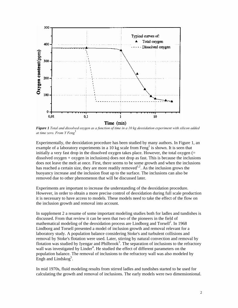
Figure 1 Total and dissolved oxygen as a function of time in a 10 kg deoxidation experiment with silicon added at time zero. From Y Feng1 Experimentally, the deoxidation procedure has been studied by many authors. In Figure 1, an example of a laboratory experiments in a 10 kg scale from Feng1 is shown. It is seen that initially a very fast drop in the dissolved oxygen takes place. However, the total oxygen (= dissolved oxygen + oxygen in inclusions) does not drop as fast. This is because the inclusions does not leave the melt at once. First, there seems to be some growth and when the inclusions has reached a certain size, they are more readily removed1,2. As the inclusion grows the buoyancy increase and the inclusion float up to the surface. The inclusions can also be removed due to other phenomenon that will be discussed later. Experiments are important to increase the understanding of the deoxidation procedure. However, in order to obtain a more precise control of deoxidation during full scale production it is necessary to have access to models. These models need to take the effect of the flow on the inclusion growth and removal into account. In supplement 2 a resume of some important modeling studies both for ladles and tundishes is discussed. From that review it can be seen that two of the pioneers in the field of mathematical modeling of the deoxidation process are Lindborg and Torsell2. In 1968 Lindborg and Torsell presented a model of inclusion growth and removal relevant for a laboratory study. A population balance considering Stoke's and turbulent collisions and removal by Stoke's flotation were used. Later, stirring by natural convection and removal by flotation was studied by Iyengar and Philbrook3. The separation of inclusions to the refractory wall was investigated by Linder4. He studied the effect of different parameters on the population balance. The removal of inclusions to the refractory wall was also modeled by Engh and Lindskog5. In mid 1970s, fluid modeling results from stirred ladles and tundishes started to be used for calculating the growth and removal of inclusions. The early models were two dimensionional.

3
Table 1 lists the published studies6,7,8,9,10,11,12,13,14,15,16,17,18 that used fundamental transport equations to solve the fluid flow including the turbulent properties of the flow. Table 1. Summarizing table over CFD models considering inclusion growth and/or removal. From supplement 2
Referens Growth Removal Reox
Nakanishi & Szekely 1975 2Eq N 2D sep Y N N N N N N N N N N ladle ind. **Shirabe & Szekely 1983 k-ε N 2D sep Y N N N Y N N N N N N RH (gas)Johansen et al 1986 k-ε N 2D sep N N N N Y N Y Y N N Y ladle gasTacke & Ludwig 1987 k-ε N 3D int N N N N Y N N N N N N tund noIlegbusi & Szekely 1989 k-ε Y 3D int Y N N N Y N N N N N N tund noKaufmann et al 1993 k-ε N 3D - N N N N Y N N N N N N tund no +Sinha & Sahai 1993 k-ε N 3D sep Y N N N Y N N Y N N N tund noJoo, Han & Guthrie 1993 k-ε Y 3D int N N N N Y N N N N N N tund noHallberg 1996 k-ε N 3D sep Y Y N N Y N N Y N Y N ladle gas/indMiki et al 1997 k-ε N 3D sep Y Y N N Y Y N N N N N RH (gas) ++Wakoh et al 1999 k-ε N 3D sep Y Y N Y Y Y N N Y N N ladle gasMiki & Thomas 1999 k-ε Y 3D sep Y Y N N Y N N N N N N tund no ++Tozawa et al 1999 k-ε Y 3D int Y Y N Y Y N N N N N N tund no ++
N = no, Y = yes* = removal to slag by turbulent diffusion** = inclusions over a certain size was considered floated out. + = no inclusion model calculated in the model ++ = considering clusterformation Today, three-dimensional models have become more common. Some quite comprehensive models concerning growth and removal has been developed in the late 1990s15-18. So far, the model considering most aspects of inclusion behavior is by Wakoh et al16. Their model was for a gas-stirred ladle and considered growth due to turbulent and Stoke’s collisions and Brownian motion. Furthermore, removal by buoyancy and bubble flotation and dispersion of slag into the melt were taken into account. Despite the earlier modeling efforts presented in Table 1, there has not been a single model that considers all growth and removal mechanisms for inclusions in stirred ladles. It is also striking that there does not seem to be enough studies to conclude which of the removal phenomenon’s that are the most important ones and if some should be used under certain conditions. For example, the importance of bubbles for the removal of inclusions through bubble flotation during gas stirring in ladles has not been studied in a critical manner. The work presented in this thesis has been focused on increasing the knowledge of the importance of different growth and removal mechanisms during ladle treatment for different stirring conditions. The majority of the work is carried out using a static modeling approach, where initially the fluid flow and turbulence parameters are calculated using fundamental mathematical models. Thereafter, the output from these calculations has been used in a

4
separate model for prediction of inclusion growth and removal. In summary, the work has been focused on the following three topics: 1. A determining of which of six mechanisms that are important to consider when modeling
inclusion growth in induction-stirred ladles (Supplement 1). 2. Growth and removal of inclusions in gas-stirred ladles using both in a static and a
dynamic modeling approach (Supplement 2). 3. Use of a new spherical cap bubble flotation model to study removal of inclusions in gas-
stirred ladles based on a static modeling approach (Supplement 3).
5
2. THEORY FOR INCLUSION GROWTH After the deoxidant is added to the steel bath it melts and dissolves. Thereafter, a rapid reaction with dissolved oxygen occurs, which leads to the formation of inclusions. The critical radius (i.e. the minimum radius where the inclusions are considered to be stable) of SiO2 and Al2O3 inclusions has been estimated to be in the range of 6 to 32 Å1,19. Following the initial nucleation, different growth mechanisms have been proposed: • Diffusion of oxygen and deoxidant to the surface of the inclusion • Diffusion coalescence, so-called Ostwald ripening • Collision growth due to turbulence, buoyancy differences (Stokes collisions), velocity
gradients in laminar shear zones and Brownian motion. The diffusion growth of inclusions is quite fast and is over in a short period. This has been shown by Gatellier, Torsell and Olette20 and Torsell and Olette21 through electrochemical measurement where the activity of the dissolved oxygen shows a very rapid drop after the deoxidant is added. Locking at a typical deoxidation experiment the oxygen is typically a function of the time as seen in figure 1. 2.1 Diffusion coalescence Lindborg and Torsell showed that diffusion coalescence or " Ostwald ripening" is not an important phenomenon2. They calculated the diffusion coalescence with the LSW theory22,23. Their conclusion was that it would take about 30 minutes for SiO2 particles with a diameter of 2.5 µm to grow to an average size of 3.0 µm in a molten steel at 1600° C and a 100 ppm dissolved oxygen content. 2.2 Inclusion Growth due to Collisions Lindborg and Torsell2 observed that the inclusions grew during deoxidation and that this growth promoted removal rate because of the increased buoyancy. Neither the initial diffusion growth, which is over in a relatively short time, or the diffusion coalescence could explain this growth. In Lindborg and Torsell's experiments it was found that growth due to collisions seemed to be the most likely explanation. The number of collisions of a certain type can be calculated by the general equation 1 below
jiijji nnW
dtdn
=, (1)
where ni and nj is the number of inclusions of some size and Wij is the collision volume of a certain collision phenomenon. It is called the collision volume since it has the unit m3/s. It is a measure of the willingness for a certain type of collision to occur. The collision volume is used in the work below to determine which type of collision is most likely to occur.

6
2.2.1 Collisions due to Turbulence A theoretical study by Saffman and Turner is the most commonly used when modelling collisions between particles in a turbulent flow. Their equation has later been modified by Nakanishi and Szekely6 and Taniguchi and Kikuchi24 into the following expression
( )Fe
jiij rrWνεαπ 32
13,1 += (2)
where α is the collision efficiency, ri and rj are the radius of the two colliding inclusions, ε is the turbulent energy dissipation and νFe is the kinematic viscosity of the steel.
2.2.2 Collisions due to Buoyancy Differences The inclusions rise trough the steel bath due to the density difference between the steel and the oxide. The rising velocity increases with increasing size. Therefore, larger inclusions will catch up with smaller one’s. The collision volume of these types of collisions can be expressed as suggested by Lindborg and Torssell2 using the following equation
( ) ( ) jijiFe
iFeij rrrrgW −+−= 3
92
µρρπ (3)
where g is the gravitational acceleration, µFe is the dynamic viscosity and ρFe and ρi are the densities of the steel and inclusion respectively. This type of collision is also called “Stoke's collision” as the buoyancy velocity is assumed to follow Stoke's law for round particles.
2.2.3 Collisions due to Laminar Shear As there can be velocity gradients in the laminar flow, inclusions can move along different streamlines having different velocities. An inclusion on a faster streamline can therefore catch up with one moving with a slower velocity. Smoluchowski25 has suggested the following equation for collision volume due to laminar shear:
( )dxdurrW jiij
3
34 += (4)
where du/dx is the velocity gradient in the direction where laminar flow exists.
2.2.4 Collisions due to Brownian Motion

7
Very small inclusions move randomly in fluids. This movement has been named after its discoverer. Collisions of inclusions due to Brownian motion was not accounted for, or considered of less importance2, in the early literature dealing with models for deoxidation. Later, in the studies by Taniguchi and Kikuchi24 this growth mechanism was taken into account. The diffusivity of inclusions is described by the Stoke-Einstein’s equation and the collision volume is written as:
( )jijiFe
ij rrrr
kTW +
+= 11
32µ
(5)
where k is the Boltzmann constant, T is the temperature.

8
3. THEORIES FOR REMOVAL OF INCLUSIONS As inclusions grow in size and get removed, a dynamic deoxidation model have to into account this fluctuation in the population of inclusions. A population balance can be calculated as
++−−= ∑∑∞
=
−=
=+= dtkdN
dtkdN
dtkdN
nnWnnWdt
dn BSWki
iikji
ki
kjiiij
k )()()(21
1
1
,1 (6)
where the first sum represents the number of inclusions that grow to a certain size rk. The second sum represents the number of inclusions that leave the size class by growing larger. Wij and Wik is the sums of the different collision volumes. NW is the removal to the refractory lining, NS is the removal to slag and NB is the removal by bubble flotation. 3.1 Removal to the Slag As inclusions have great buoyancy they tend to float up to the slag. A removal frequency equation can be written as
iFe
iFes C
rgA
dtdN ⋅
−⋅=
µρρ
9)(2 2
(7)
where As is the surface area and Ci is inclusion concentration. This removal frequency does not consider any interfacial influence at the steel-slag interface. Neither does it account for any formation of a slag emulsion in the steel-slag region. 3.2 Removal to the Refractory Lining Inclusions, and especially alumina, are known to cause nozzle clogging in continuos casting. This is an effect from alumina sticking to the nozzle wall. Similar phenomenon are believed to happen in a stirred ladle. There are different models for this phenomenon8,12,14,19. In this work a model by Linder26 is used.
i
Fe
w Cd
UrAdtdN ⋅⋅⋅=
41
43
47
0003.0
υ (8)
where Aw is the refractory surface are and Ū is the bulk flow velocity. The parameter d is the tube diameter and is here somewhat arbitrary set to 0.01 m as suggested by Linder26. 3.3 Removal due to Bubble Flotation For the removal by bubbles several models were studied. Three where the bubbles were assumed to be spherical and one were the bubbles were spherical caps.
9
3.3.1 Spherical Bubble Model 1 In an article by Wang, Lee and Hayes27, a model for calculation of the probability of a collision between an inclusion and a bubble is presented. The equations are valid for the collision between an inclusion and a spherical bubble rising trough the steel. The overall probability for an inclusion getting collected and lifted up to the surface can be described as the product of two probabilities as in equation (9):
ac PPP = (9) where Pc, and Pa are the probabilities of collision and adhesion, respectively. The inclusions are assumed to stick to the bubble once being attached. The inclusions detachment for the very small inclusion with very small inertia is insignificant and can for that reason be set to zero27. The bubble lifts the inclusion up to the surface slag and it is assumed that it is removed successfully from the steel. Wang, Lee and Hayes used a model by Yoon and Lutrell28 to calculate the collision probability. In Yoon´s model an empirical stream equation was fitted to experimental data. This equation was modified by Wang, Lee and Hayes with higher order terms and the effect of relative velocity is taken in concern. The calculation routine can be read in the supplement 3 and in the reference27. Taking the overall collision probability, the number of inclusions, the number of bubbles, the relative velocity, the collision area, and the concentration of inclusions into account a removal equation can be written as follows:
( ) ibrbi CNvrrPdtdN 2+= π (10)
where vr is the relative velocity between the inclusion (i.e. steel) and the bubble (i.e. gas), Nb is the number of bubbles in the specific calculation cell (data from CFD calculation), and Ci is the inclusion concentration.
3.3.2 Spherical Bubble Model 2 As in model 1 it is assumed that the inclusion once it is attached to the spherical bubble it is lifted up to the slag, where it is removed. In an article by Miki et al15 an equation for “the rate of inclusion entrapment” was expressed as
VbvN
S rbb
π2
= (11)
where V is the volume of the steel and b is the critical entrapment radius, calculated from a stream function for potential flow around spheres. The critical entrapment radius is used for calculating the collision area (b2π). In Miki et al´s article the collision efficiency between bubbles and inclusions was arbitrarily set to 3%. However, the collision efficiency is here described as suggested by Frisvold et al29 in a modified manner to suite this application:

10
bb
i
DD
Re23
23=η (12)
where Reb is the Reynolds number for the bubble. The flow is assumed to be a potential flow and the inclusion is assumed to follow a streamline around the bubble. If the collision efficiency and the number of inclusions are taken into account, the removal equation can be written as:
ibrbb
i CNvbDD
dtdN 2Re
23
23 π⋅= (13)
3.3.3 Spherical Bubble Model 3 Engh19 has presented a simpler model expressing the flotation of inclusions by spherical bubbles. This is similar to what also has been derived by Sutherland30. The probability of collision is written as:
b
ic r
rP 3= (14)
and an equation expressing the removal rate of inclusions can be expressed as:
ibrbib
i CNvrrrr
dtdN 2)(3 += π (15)
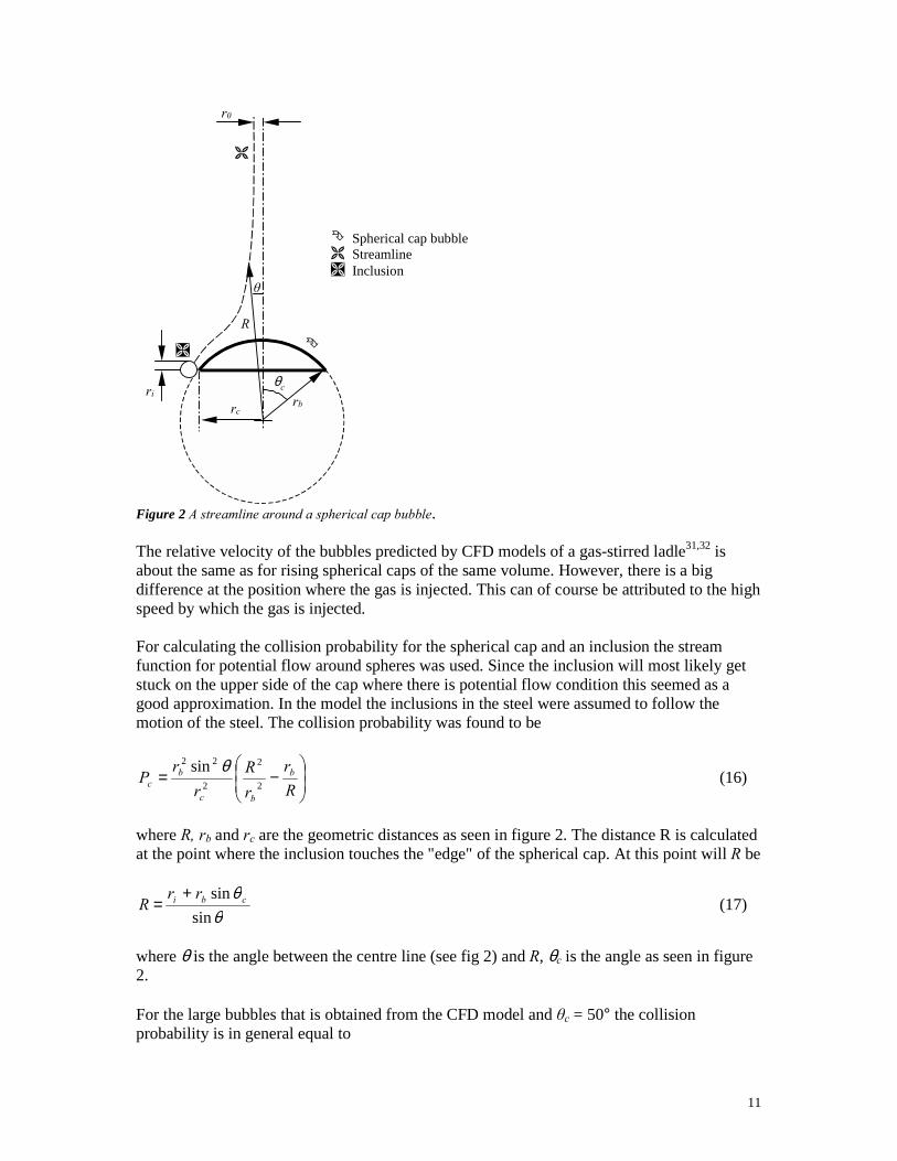
3.3.4 Spherical Cap Bubble Model When bubbles increase in size the round shape becomes unstable. In a quiescent liquid and as size increases, first an unstable phase is formed and as it becomes a bit larger it takes the shape of a spherical cap. Based on the results from models of gas-stirred ladles, the predicted bubbles are quite large31,32. Therefore, a new model was developed, which takes the effect of the shape on the flotation of inclusions into consideration. Only a short presentation of the model given here, but a detailed description can be found in supplement 3. Spherical caps are formed when the size of the gas bubble becomes so large that surface and friction forces no longer have an impact and the shape is controlled mainly by buoyancy and inertial forces33. Davies and Taylor examined the flow around spherical caps. They retrieved that the flow around the spherical cap bubble is similar to what is found for potential flow around spheres. In their experiments Davies and Taylor found that the opening angle, θc, illustrated in figure 2 was about 50 °.
11
θc
rbrc
ri
R
r0
θ
�
�
�
� Spherical cap bubble� Streamline� Inclusion
Figure 2 A streamline around a spherical cap bubble. The relative velocity of the bubbles predicted by CFD models of a gas-stirred ladle31,32 is about the same as for rising spherical caps of the same volume. However, there is a big difference at the position where the gas is injected. This can of course be attributed to the high speed by which the gas is injected. For calculating the collision probability for the spherical cap and an inclusion the stream function for potential flow around spheres was used. Since the inclusion will most likely get stuck on the upper side of the cap where there is potential flow condition this seemed as a good approximation. In the model the inclusions in the steel were assumed to follow the motion of the steel. The collision probability was found to be
−=
Rr
rR
rr
P b
bc
bc 2
2
2
22 sin θ (16)
where R, rb and rc are the geometric distances as seen in figure 2. The distance R is calculated at the point where the inclusion touches the "edge" of the spherical cap. At this point will R be
θθ
sinsin cbi rr
R+
= (17)
where θ is the angle between the centre line (see fig 2) and R, θc is the angle as seen in figure 2. For the large bubbles that is obtained from the CFD model and θc = 50° the collision probability is in general equal to

12
b
ic r
rP 3.2= (18)
An inclusion that collides with a bubble has to break through the bubble surface and make contact with the gas. This process takes a certain time (induction time). If this time is longer than the time the inclusion slides over the bubble (sliding time) it will not make an aggregate with the bubble. The probability of the aggregate formation is called the probability of adhesion. In the derivation of an adhesion probability the procedure of Yoon and Lutrell28 was followed. In the final expression the induction time, ti, was used and the adhesion probability was expressed as:
( )
( )
( )
+
≈
+
++
=
ib
ir
ib
ir
c
icb
iba
rrtv
rrtvrr
rrP
23
exp
250tan
arctan2sin7.1
23
exp
2tan
arctan2sinsin
2
22
θ
θ
(19)
when θc = 50°. There are two limiting27 cases that determine the induction time: plane contact and point contact. Both cases were calculated. The overall removal probability and removal frequency were calculated using equation 9 and 10, respectively.
13
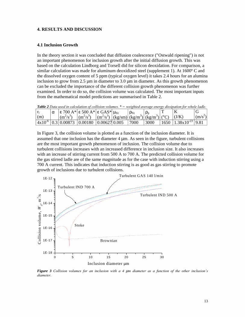
4. RESULTS AND DISCUSSION 4.1 Inclusion Growth In the theory section it was concluded that diffusion coalescence ("Ostwald ripening") is not an important phenomenon for inclusion growth after the initial diffusion growth. This was based on the calculation Lindborg and Torsell did for silicon deoxidation. For comparison, a similar calculation was made for aluminum deoxidized steel (supplement 1). At 1600º C and the dissolved oxygen content of 5 ppm (typical oxygen level) it takes 2.4 hours for an alumina inclusion to grow from 2.5 µm in diameter to 3.0 µm in diameter. As this growth phenomenon can be excluded the importance of the different collision growth phenomenon was further examined. In order to do so, the collision volume was calculated. The most important inputs from the mathematical model predictions are summarised in Table 2. Table 2 Data used in calculation of collision volumes. * = weighted average energy dissipation for whole ladle. ri (m)
α ε 700 A* (m2/s3)
ε 500 A* (m2/s3)
ε GAS*(m2/s3)
µFe (kg/sm)
ρFe (kg/m3)
ρp (kg/m3)
T (°C)
K (J/K)
G (m/s2)
4x10⁻⁶ 0.3 0.00873 0.00180 0.00627 0.005 7000 3000 1650 1.38x10⁻²³ 9.81 In Figure 3, the collision volume is plotted as a function of the inclusion diameter. It is assumed that one inclusion has the diameter 4 µm. As seen in the figure, turbulent collisions are the most important growth phenomenon of inclusion. The collision volume due to turbulent collisions increases with an increased difference in inclusion size. It also increases with an increase of stirring current from 500 A to 700 A. The predicted collision volume for the gas stirred ladle are of the same magnitude as for the case with induction stirring using a 700 A current. This indicates that induction stirring is as good as gas stirring to promote growth of inclusions due to turbulent collisions.
0 5 10 15 20 25 301E-18
1E-17
1E-16
1E-15
1E-14
1E-13
1E-12Turbulent GAS 140 l/min
Turbulent IND 700 A
Turbulent IND 500 A
Stoke
BrownianCol
lisio
n vo
lum
e, W
ij, m
3 /s
Inclusion diameter µm
Figure 3 Collision volumes for an inclusion with a 4 µm diameter as a function of the other inclusion’s diameter.

14
For Stoke’s collisions, the collision volume increases with an increased difference in radius length raised to the fourth power. If the inclusions are of the same size, Stoke’s collisions have very little influence on inclusion growth. If the size of one of the two inclusions is much larger, then the importance of Stoke´s collisions increases. When an inclusion of 4 µm collides with one of 30 µm or larger Stoke’s collisions has a collision volume of the same magnitude as turbulent collisions. Brown’s collisions have a negligible impact on growth. The only time they have a greater bearing on the collision volume is when the size of one of the two particles becomes very small (<< 1µm). However, that is of less importance for the current case. The velocities and energy dissipation rates vary in the ladle, which result in different collision volumes throughout the ladle. In order to quantify the velocity gradients on a larger scale, the velocity variation at certain positions was calculated. Based on this information, the collision volumes due to inclusion growth caused by laminar shear was calculated. In Table 3, the fraction of the collision volume due to shear collisions in comparison to the collision volume due to turbulent collision is given. The information is given as average, minimum and maximum values of the calculations from the different areas of the stirred ladles. It was found for the three stirring cases that on average the collision volume of shear collisions was about 0.6-1.3% of the turbulent collision volume. Table 3 The average, minimum and maximum fraction of shear collisions compared to turbulent collisions (Wij,
shear / Wij, turbulence). Stirring Average Minimum Maximum Induction, 500 A 0.013 0.00052 0.019 Induction, 700 A 0.006 0.00073 0.0089 Gas 0.0095 0.00019 0.017 In equation (4) valid for laminar shear collisions and in equation (2) valid for turbulent collisions, the inclusion size has the same influence on collision volume. Therefore, it can be concluded for collisions between inclusions of all sizes, that laminar shear collisions may be of negligible importance in comparison with turbulent collisions both for induction and gas stirred ladles. 4.2 Inclusion Removal In supplements 2 and 3, a removal frequency based on an arbitrarily set inclusion concentration, Ci, of 1 inclusion/m3 was calculated for a gas stirred ladle. This inclusion concentration was chosen for easy comparison. The removal rate in each cell was summed up. In supplement 2 results for different inclusion sizes is presented as in figure 4 for removal to slag, wall, bottom and by bubble flotation by spherical model 1 to 3.

15
0 5 10 15 20
1E-8
1E-7
1E-6
1E-5
1E-4
1E-3
0.01
To side wall
To bottom
To slag
Model 1a (tFR)
Model 1b (tFT)
Model 2
Model 3
Rem
oval
1/s
Diameter µm Figure 4 The removal frequency for removal to the slag, wall, bottom and by bubble flotation by spherical model 1-3). It can be seen in figure 4 that the removal to slag and the refractory lining is higher than by bubble flotation. The removal by buoyancy flotation (Stokes flotation) shows a considerable dependence of the size of the inclusion. For the larger inclusions, it has the highest value in removal frequency and when the inclusion size goes down it drops dramatically. The difference between removal the side wall and the bottom - which are both calculated by equation (8) - is mainly explained by the slower velocity near the bottom (Ū lower). It is also clear from figure 4 that the different models for removal by bubble flotation gave very different results. Model 1 shows low values compared with the other bubble flotation models. This is mainly explained by the fact that different stream function is used. In Model 1 two contact models between bubble and inclusion are used for calculating the adhesion probability. The different contact models give different results. The plane contact model will generally give lower values than the point contact model. The true contact model will most likely be somewhere between the lines as the point and plane contact is two extreme cases. But that has to be further studied. In the CFD model itself the gas fraction is never equal to zero. Because of this fact the removal by bubbles was calculated in the cells containing more than 0.5 percent gas. This percentage was found to be a good cut off limit. The CFD cell height was used as the distance at which the collision area, i.e. b, was calculated for Model 2. Model 2 and 3 show quite similar shape and it may be explained by that they are calculated based on the same stream function. Model 2 is though much higher then Model 3. This is an effect of the quite high Reynolds numbers (large bubbles) in the CFD model31 and that the critical entrapment radius, b, has a high value. The entrapment radius is calculated quite near the bubble as the CFD cell height is used. In the calculations for the bubble flotation models 1 to 3 which figure 4 is based on, the assumption is made that the bubbles are round. This could strongly be questioned. The average bubble diameter found in the CFD model of a gas stirred ladle was 6.38 cm diameter. This size is clearly in the region of taking the form of a spherical cap33. So in supplement 3, a

16
model for bubble flotation by spherical caps was developed. Similar to supplement 2, a calculation for the spherical caps was done. The shape seemed to have a great importance on the removal by bubble flotation. In figure 5 the removal to the slag, refractory lining and by spherical cap bubble flotation considering the plane contact model is shown.
0 20 40 60 80 1001E-8
1E-7
1E-6
1E-5
1E-4
1E-3
0.01
0.1
To side wall
To bottom
To slag
S. Cap plane contact
Rem
oval
1/s
Diameter µm Figure 5 The removal frequency for removal to the wall, refractory and by spherical cap bubbles (plane contact case). The bubble flotation by spherical caps, plane contact, shows the highest removal frequency for smaller inclusions then about 25 µm. The spherical cap model will be further commented below where the different bubble flotation results are presented. In summary, all suggested mechanisms suggest that big inclusions are more easily removed than smaller inclusions. The largest increase in removal with increased inclusion size is observed for removal to the slag.
0 20 40 60 80 1001E-8
1E-7
1E-6
1E-5
1E-4
1E-3
0.01
Model 1 point contact
Model 1 plane contact
Model 2
Model 3
S. Cap point contact
S. Cap plane contact
Rem
oval
1/s
Diameter µm Figure 6 The removal frequency for the different bubble flotation models. In figure 5 only results from one bubble flotation model was presented, namely a model representing spherical cap bubbles. In figure 6, the removal rate of inclusions predicted using six different bubble flotation models is plotted.

17
The highest removal rates are predicted when using the spherical cap model and assuming a plane contact between the bubble and the inclusion. From the CFD model predictions it was seen that the average bubble diameter for an assumed round bubble is 6.38 cm. For a spherical cap bubble with a corresponding volume as a round bubble of a 6.38 cm diameter, the diameter is about 14.6 cm. The large size seems to give a high value for the removal rate. This big bubble is a larger collector of inclusions as it has a high area to volume ratio. The effect of the large size is seen in the spherical cap model with plane contact. Model 2 shows a quite high value, but this model is probably not good because it overestimates the rate of inclusion entrapment as the distance b is to short. The varying results for the bubble flotation models using different contact models obvious points out that the adhesion of inclusions to bubbles should be further studied.
18
5. CONCLUSIONS Inclusion Growth in an Inductively Stirred Ladle In the comparison of the importance of different growth mechanisms, CFD simulation results from a fundamental model of an induction-stirred ladle have been used as input in the calculations. Based on the growth calculations it was concluded that four of the growth mechanisms need not to be considered since they contribute so little: i) diffusion of oxygen and aluminum to the inclusion surface, ii) diffusion coalescence, iii) Brown motion collision, and iv) laminar shear collision. The major contributor to inclusion growth is turbulent collision. Growth due to Stoke’s collisions is also somewhat important if large differences among inclusion sizes exist. In summary, the specific new findings from this study are the following: • a term representing the collision efficiency should be included in the equations describing
growth due to Brown motion (Equation 5), laminar shear (Equation 4), and Stoke’s collisions (Equation 3)
• laminar shear collisions do not significantly contribute to inclusion growth in an induction-stirred ladle
• Stoke’s collisions contribute to inclusion growth if the difference in inclusion radius is more than approximately 13 µm
• the variation in fluid flow and turbulent properties in different parts of the ladle should be incorporated into a growth model since it can affect average turbulent collision volumes by 25 to 30%
Inclusion Growth and Removal in a Gas-stirred Ladle In order to compare different growth mechanisms, the volumes of laminar shear collisions, turbulent collisions, and Stokes collisions were calculated. Turbulent collisions and Stokes collisions appeared to be of greatest significance in inclusion growth. The contribution of laminar shear collisions to growth was deemed negligible compared to that of turbulent collisions. The most important mechanisms of inclusion removal were found to be removal to the top slag and removal by bubble flotation, assuming spherical-cap bubbles and plane contact. When the bubbles were assumed to be spherical, resulting removal rates were lower than when they were assumed to be spherical caps. More research is needed to obtain a better understanding of the importance of bubble flotation on inclusion removal. Experiments are clearly needed to determine which model concepts produce predictions in best agreement with corresponding data from actual steelmaking processes. In summary, the specific findings of this study were that: • turbulent collision was the most significant/dominant growth mechanism for an inclusion
of 4 µm in diameter colliding with an inclusion of up to 30 µm in diameter. However, for a 4-µm inclusion colliding with a 30-µm (or larger) inclusion, the Stokes collision mechanism was also found to be a significant factor.
• laminar shear collision was deemed a negligible mechanism regarding inclusion removal in gas-stirred ladles; the predicted volume was hundred times lower than that of turbulent collisions.
• inclusions larger than 25 µm were predicted to mainly be removed to the slag by Stokes flotation and smaller inclusions primarily separated by spherical-cap bubble flotation (assuming plane contact between the inclusion and the bubble).
19
6. FUTURE WORK While carrying out the present study some ideas of future work have been identified: • The findings using the spherical cap model calculations shows a need to study the
adhesion of inclusions on gas bubbles and how the induction time should be calculated. A good experiment using steel may though be difficult to design.
• In supplement 2, concentration gradients resulted from the removal of inclusions. A full
scale experiment for the verification of concentration gradients in liquid steel is necessary. This is planned to take place in the near future.
• The equation for turbulent collisions considers the collision efficiency, α. For the other
collision phenomena there has been no such collisions efficiency proposed. It is though reasonable to believe that the collision efficiency is not equal to one. A collision efficiency for Stoke’s collision would be most interesting to develop, since it has most effect on growth besides turbulent collisions.
• For the removal to the slag interfacial tension and slag dispersion is not taken into
consideration in the current equations. This is of course a difficult thing to model, but it may be needed to do so in order to get the full understanding of this removal mechanism.
20
REFERENCES 1 Feng Y, A kinetic study on the deoxidation of liquid steel by silicon and aluminium, PhD thesis, Royal Institute of Technology (1995) 2 Lindborg U. and Torssell K., A collision model for the growth and separation of deoxidation products, Trans. Met. Soc. AIME, vol 242 (1968), pp. 94 - 102. 3 Iyengar R.K. and Philibrook W.O. A mathematical model to predict the growth and elimination of inclusions in liquid steel stirred by natural convection, Met. Trans., vol. 3 (1972), pp. 1823-1830. 4 Linder S., Hydrodynamics and collisions of small particles in a turbulent metallic melt with special reference to deoxidation of steel, Scandinavian Journal of Metallurgy 3 (1974) 137-150 5 Engh T.A. and Lindskog N., A fluid mechanical model of inclusion removal, Scandinavian Journal of Metallurgy vol. 4 (1975) no. 2 pp 49-58 6 Nakanishi K. and Szekely J., Deoxidation kinetics in a turbulent flow field, Trans. ISIJ, vol 15 (1975) pp. 522-530 7 Shirabe K. and Szekely J., A mathematical model of fluid flow and inclusion coalescence in the R-H vacuum degassing system, ISIJ International, vol. 23 (1983) pp. 465-474 8 Johansen S.T., Boysan F. and Engh T.A., Numerical calculations of removal of inclusions and dissolution of refractory in a bubble stirred ladle., Procceedings Fourth Japan-Nordic Countries Joint Symposium on Science and Technology of Process Metallurgy, Tokyo, Japan, November 1986, pp 182-215 9 Tacke K-H. and Ludwig J.C., Steel flow and inclusion separation in continuous casting tundishes., Steel Research vol 58 (1987) no6, pp. 262-270 10 Ilegbusi O.J. and Szekely J., Effect of magnetic field on flow, temperature and inclusion removal in shallow tundishes. ISIJ International, vol 29 (1989), no 12, pp. 1031-1039 11 Kaufmann B., Niedermeyr A., Sattler H. and Preuer A., Separion of nonmetallic particles in tundishes., Steel Research vol 64 (1993) no 4, pp. 203-209 12 Sinha A.K. and Sahai Y., Mathematical modeling of inclusion transport and removal in continuous casting tundishes., ISIJ International, vol 33 (1993), no5 pp. 556-566 13 Joo S., Han J.W. and Guthrie R.I.L., Inclusion Behavior and Heat-Transfer Phenomena in Steelmaking Tundish Operations. II. Mathematical Model for Liquid Steel in Tundishes. Metallurgical Transactions B (USA), vol. 24B (1993), no. 5, pp. 767-777 14 Hallberg M., En matematisk modell för desoxidation av en omrörd stålsmälta, , Tech. lic. Royal Institute of Technology (1996), ISSN 0281-8604, ISBN 91-7170-949-2 15 Miki Y., Shimada Y., Thomas B.G. and Denisov A., Model of inclusion removal during RH degassing of steel, I&SM, ISS vol 28 (1997) no. ??? pp. 31-38 16 Wakoh M., Fuchigami K., Endoh K., Imamura N., Kiyose A. and Sawada I., Analysis of inclusion behavior in a ladle refining process by using newly developed coagulation model., Scanmet I, Luleå, Sweden, June, 1999, pp. 267-274 17 Miki Y. and Thomas B.G., Modeling of inclusion removal in a tundish. Metallurgical and Materials Transactions B, vol 30B (1999) pp. 639-654 18 Tozawa H., Kato Y., Sorimachi K. and Nakanishi T., Agglomeration and flotation of alumina clusters in molten steel., ISIJ International, vol 39 (1999) no 5, pp. 426-434 19 Engh T. A. Principles of metal refining. Oxford university press. (1992) ISBN 0-19-856337-X 20 Gatellier C, Torsell K and Olette M, Application des force électromotorice à l'étude cinétique de la désoxydation du fer liquide, C. R. Acad. Sc. Paris Série C (1968) pp 1753-1756

21
21 Torsell K and Olette M, Influence de la formation d'amas sur l'élimination des inclusions d'alumine provant de la désoxydation du fer liquide par l'aluminium, Revue de Métallurgie Déc 1969 (1969), pp 816-822 22 Lifshitz I.M. and Slyozov V.V. The kinetics of precipitation from supersaturated solid solutions, J. Phys. Chem. Solids, vol 19 (1961), pp. 35-50 23 Wagner C., Theorie der Alterung von Niederschlägen durch Umlösen. Electrochem. 65 (1961) pp 581-591 24 Taniguchi S. and Kikuchi A., Mechanisms of collision and coagulation between fine particles in fluid, Tetsu-to-hagane, vol. 78 (1992), pp. 527-535. 25 Levich V.G. Physicochemical hydrodynamics, Prentice-Hall (1962) 26 Linder S., Hydrodynamics and collisions of small particles in a turbulent metallic melt with special reference to deoxidation of steel, Scandinavian Journal of Metallurgy 3 (1974) 137-150 27 Wang L., Lee H-G. and Hayes P., Prediction of the optimum bubble size for inclusion removal from molten steel by flotation., ISIJ International, vol. 36 (1996) no 1 pp. 7-16 28 Yoon R.H. and Lutrell G.H., The effect of bubble size on fine particle flotation. Mineral Proess. and Extractice Metall. Rev., vol 4 (1989) pp. 101-122 29 Frisvold F., Engh T.A., Johansen S.T. and Pedersen T., Removal of inclusions - a survey and comparison of principles. Light Metals 1992, San Diego, California, USA, March 1992, The Minerals, Metals & Materials Society (USA), pp. 1125-1132 30 Sutherland K.L, J. Phys. Chem., Vol. 52, 1948, pp 394 31 Jönsson P. and Jonsson L., “A model of a gas-stirred ladle” Sc. J. Met. 1995, pp. 194-206 32 Jonsson L. and Jönsson P., “Modeling of Fluid Flow Conditions round the Slag/Metal Interface in a Gas-stirred Ladle” ISIJ Int., Vol. 36 1996, pp. 1127-1134. 33 Oeters F. “Widerstandsgesetze für Gasblasen” Metallurge der Stahlherstellung, Springer-VerlagBerlin, 1989 pp 230-236