Embed Size (px)
Citation preview
GROUP 37
POWER STEERINGCONTENTS
GENERAL INFORMATION . . . . . . . . 37-2
SERVICE SPECIFICATIONS. . . . . . . 37-4
SPECIAL TOOLS. . . . . . . . . . . . . . . . 37-5
TROUBLESHOOTING . . . . . . . . . . . . 37-8DIAGNOSIS TROUBLESHOOTING FLOW . . . . . . . . . . . . . . . . . . . . . . . . . . . . . 37-8DIAGNOSTIC FUNCTION . . . . . . . . . . . . . 37-8CHECK OF ELECTRIC POWER STEERING WARNING LAMP. . . . . . . . . . . 37-8DIAGNOSIS CODE CHART . . . . . . . . . . . . 37-9DIAGNOSTIC TROUBLE CODE PROCEDURES. . . . . . . . . . . . . . . . . . . . . . 37-10TROUBLE SYMPTOM CHART. . . . . . . . . . 37-71SYMPTOM PROCEDURES . . . . . . . . . . . . 37-72DATA LIST REFERENCE TABLE . . . . . . . 37-84ACTUATOR TEST REFERENCE TABLE. . 37-85CHECK AT ELECTRIC POWER STEERING-ECU. . . . . . . . . . . . . . . . . . . . . 37-86
ON-VEHICLE SERVICE. . . . . . . . . . . 37-87STEERING WHEEL FREE PLAY CHECK . . . . . . . . . . . . . . . . . . . . . . . . . . . . 37-87STEERING ANGLE CHECK. . . . . . . . . . . . 37-87
TIE ROD END BALL JOINT TURNING TORQUE CHECK . . . . . . . . . . . . . . . . . . . . 37-87CHECK OF STEERING FORCE TO LOCK. . . . . . . . . . . . . . . . . . . . . . . . . . . . . . 37-88STEERING WHEEL RETURN TO CENTRE CHECK . . . . . . . . . . . . . . . . . . . . 37-89TIE ROD END BALL JOINT DUST COVER CHECK . . . . . . . . . . . . . . . . . . . . . 37-89STEERING COLUMN SHAFT ASSEMBLY SHOCK ABSORBING MECHANISM CHECK . . . . . . . . . . . . . . . . . . . . . . . . . . . . 37-89
STEERING WHEEL . . . . . . . . . . . . . . 37-90REMOVAL AND INSTALLATION . . . . . . . . 37-90
STEERING SHAFT . . . . . . . . . . . . . . . 37-92REMOVAL AND INSTALLATION . . . . . . . . 37-92DISASSEMBLY AND REASSEMBLY . . . . . 37-94
POWER STEERING GEAR BOX AND LINKAGE . . . . . . . . . . . . . . . . . . 37-96
REMOVAL AND INSTALLATION . . . . . . . . 37-96INSPECTION. . . . . . . . . . . . . . . . . . . . . . . . 37-101
ELECTRIC POWER STEERING CONTROL UNIT . . . . . . . . . . . . . . . . . 37-102
REMOVAL AND INSTALLATION . . . . . . . . 37-102
GENERAL INFORMATIONPOWER STEERING37-2
GENERAL INFORMATIONM1372000100821
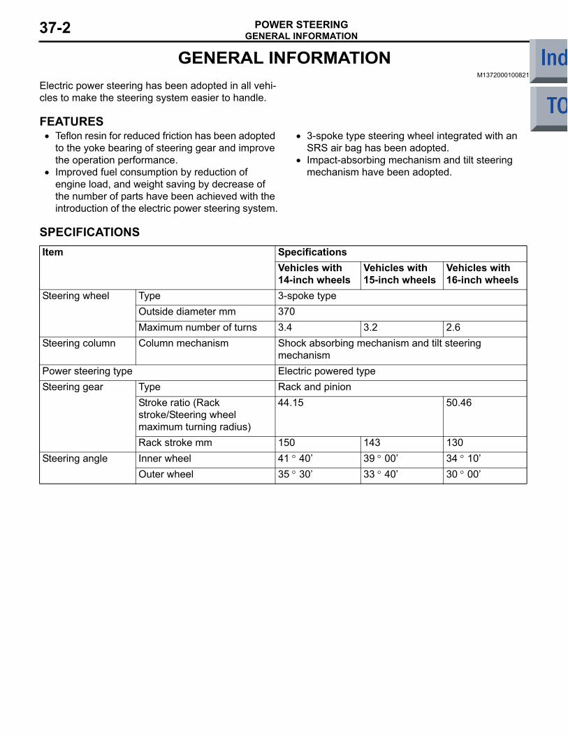
Electric power steering has been adopted in all vehi-cles to make the steering system easier to handle.
FEATURES• Teflon resin for reduced friction has been adopted
to the yoke bearing of steering gear and improve the operation performance.
• Improved fuel consumption by reduction of engine load, and weight saving by decrease of the number of parts have been achieved with the introduction of the electric power steering system.
• 3-spoke type steering wheel integrated with an SRS air bag has been adopted.
• Impact-absorbing mechanism and tilt steering mechanism have been adopted.
SPECIFICATIONSItem Specifications
Vehicles with 14-inch wheels
Vehicles with 15-inch wheels
Vehicles with 16-inch wheels
Steering wheel Type 3-spoke typeOutside diameter mm 370Maximum number of turns 3.4 3.2 2.6
Steering column Column mechanism Shock absorbing mechanism and tilt steering mechanism
Power steering type Electric powered typeSteering gear Type Rack and pinion
Stroke ratio (Rack stroke/Steering wheel maximum turning radius)
44.15 50.46
Rack stroke mm 150 143 130Steering angle Inner wheel 41 ° 40 39 ° 00 34 ° 10
Outer wheel 35 ° 30 33 ° 40 30 ° 00
GENERAL INFORMATIONPOWER STEERING 37-3
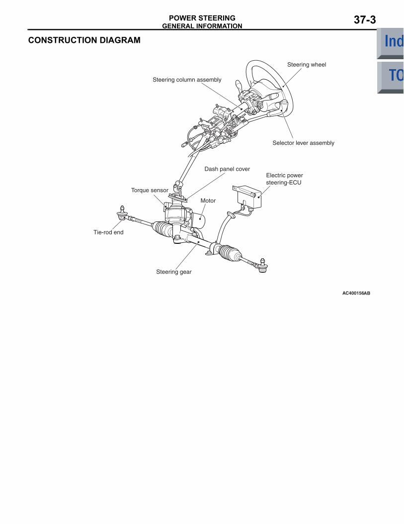
CONSTRUCTION DIAGRAM
AC400156AB
Steering wheel
Steering column assembly
Selector lever assembly
Electric power steering-ECU
Motor
Torque sensor
Tie-rod end
Steering gear
Dash panel cover
SERVICE SPECIFICATIONSPOWER STEERING37-4
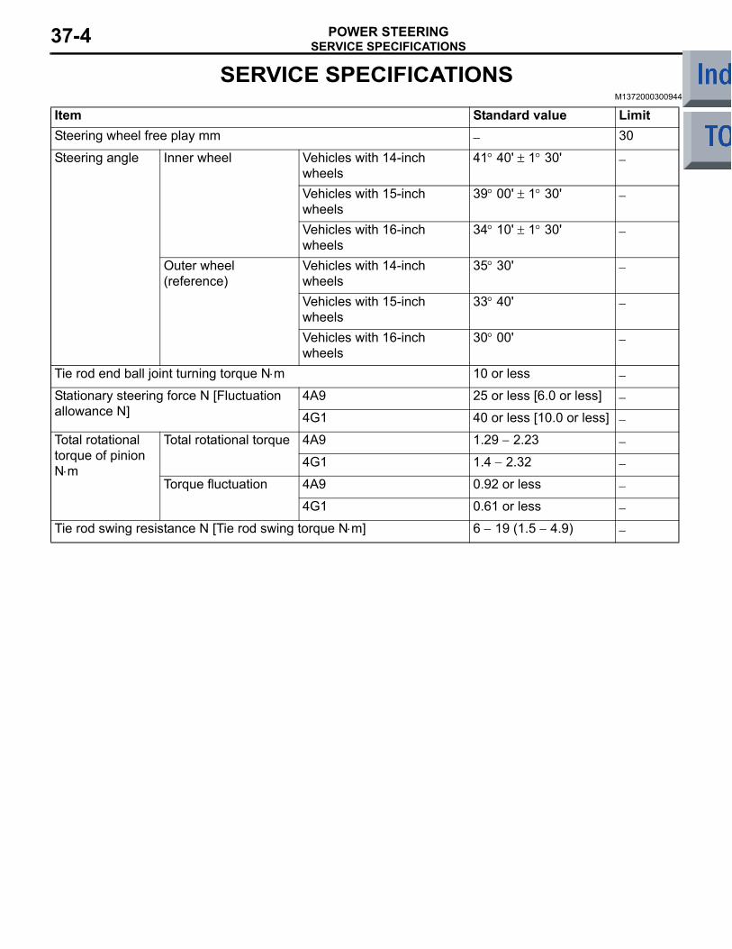
SERVICE SPECIFICATIONSM1372000300944
Item Standard value LimitSteering wheel free play mm − 30
Steering angle Inner wheel Vehicles with 14-inch wheels
41° 40' ± 1° 30' −
Vehicles with 15-inch wheels
39° 00' ± 1° 30' −
Vehicles with 16-inch wheels
34° 10' ± 1° 30' −
Outer wheel (reference)
Vehicles with 14-inch wheels
35° 30' −
Vehicles with 15-inch wheels
33° 40' −
Vehicles with 16-inch wheels
30° 00' −
Tie rod end ball joint turning torque N⋅m 10 or less −
Stationary steering force N [Fluctuation allowance N]
4A9 25 or less [6.0 or less] −
4G1 40 or less [10.0 or less] −
Total rotational torque of pinion N⋅m
Total rotational torque 4A9 1.29 − 2.23 −
4G1 1.4 − 2.32 −
Torque fluctuation 4A9 0.92 or less −
4G1 0.61 or less −
Tie rod swing resistance N [Tie rod swing torque N⋅m] 6 − 19 (1.5 − 4.9) −
SPECIAL TOOLSPOWER STEERING 37-5
SPECIAL TOOLSM1372000600882
Tool Number Name Use
MB991910
MB991826
MB991955
MB991911
MB991824
MB991827
MB991825
A
B
C
D
E
F
DO NOT USE
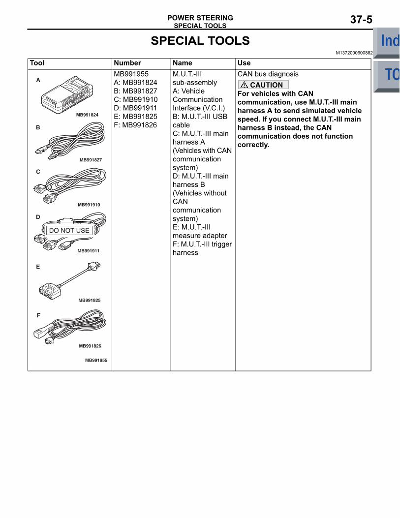
MB991955A: MB991824B: MB991827C: MB991910D: MB991911E: MB991825F: MB991826
M.U.T.-III sub-assemblyA: Vehicle Communication Interface (V.C.I.)B: M.U.T.-III USB cableC: M.U.T.-III main harness A (Vehicles with CAN communication system)D: M.U.T.-III main harness B (Vehicles without CAN communication system)E: M.U.T.-III measure adapterF: M.U.T.-III trigger harness
CAN bus diagnosisCAUTION
For vehicles with CAN communication, use M.U.T.-III main harness A to send simulated vehicle speed. If you connect M.U.T.-III main harness B instead, the CAN communication does not function correctly.
SPECIAL TOOLSPOWER STEERING37-6
MB991223
A
D
C
B
AZ
DO NOT USE
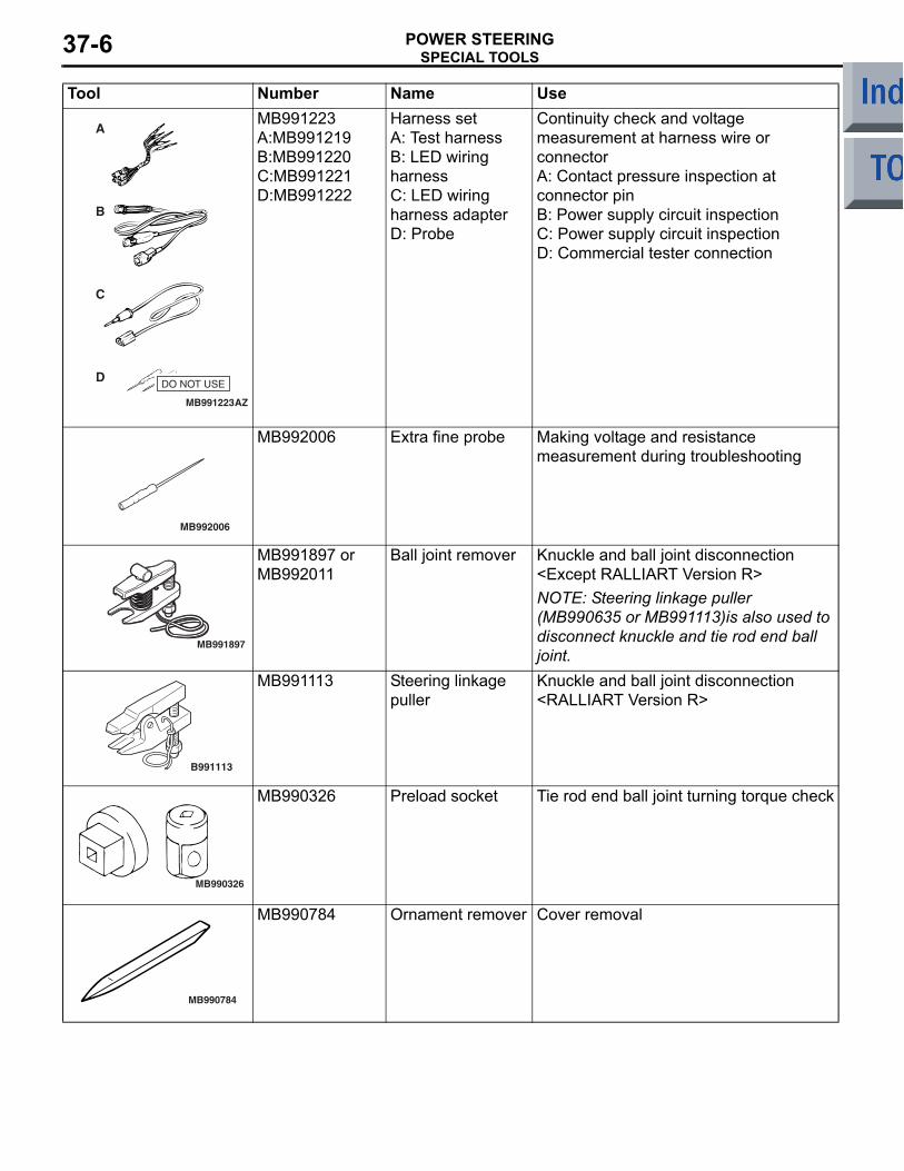
MB991223A:MB991219B:MB991220C:MB991221D:MB991222
Harness setA: Test harnessB: LED wiring harnessC: LED wiring harness adapterD: Probe
Continuity check and voltage measurement at harness wire or connectorA: Contact pressure inspection at connector pinB: Power supply circuit inspectionC: Power supply circuit inspectionD: Commercial tester connection
MB992006
MB992006 Extra fine probe Making voltage and resistance measurement during troubleshooting
MB991897
MB991897 or MB992011
Ball joint remover Knuckle and ball joint disconnection <Except RALLIART Version R>NOTE: Steering linkage puller (MB990635 or MB991113)is also used to disconnect knuckle and tie rod end ball joint.
B991113
MB991113 Steering linkage puller
Knuckle and ball joint disconnection <RALLIART Version R>
MB990326
MB990326 Preload socket Tie rod end ball joint turning torque check
MB990784
MB990784 Ornament remover Cover removal
Tool Number Name Use
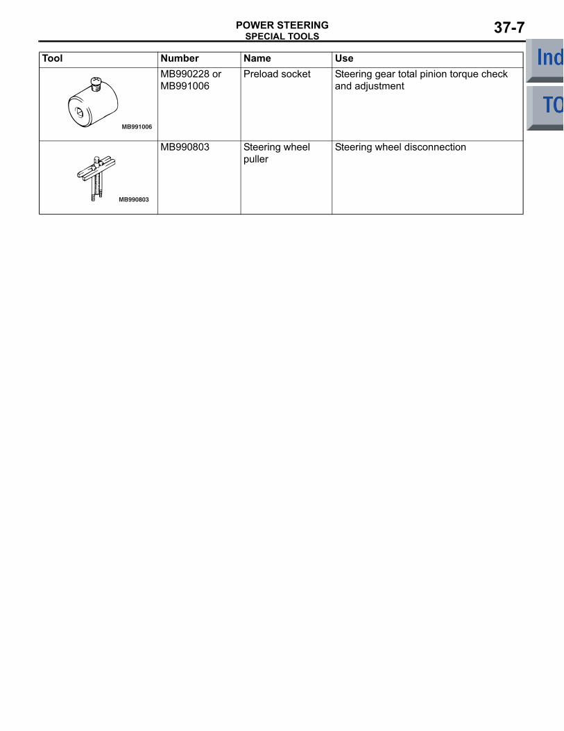
SPECIAL TOOLSPOWER STEERING 37-7
MB991006
MB990228 or MB991006
Preload socket Steering gear total pinion torque check and adjustment
MB990803
MB990803 Steering wheel puller
Steering wheel disconnection
Tool Number Name Use
TROUBLESHOOTINGPOWER STEERING37-8
TROUBLESHOOTINGDIAGNOSIS TROUBLESHOOTING FLOW
M1372007300257Refer to GROUP 00 − Contents of Troubleshooting P.00-5 .
DIAGNOSTIC FUNCTIONM1372007400049
HOW TO READ DIAGNOSIS CODEConnect the M.U.T.-III to the 16-pin diagnosis con-nector, and read a diagnosis code (Refer to GROUP 00, How to Use Troubleshooting/Inspection Service Points − Diagnosis Function P.00-7).
How to erase diagnosis codeConnect the M.U.T.-III to the 16-pin diagnosis con-nector, and erase a diagnosis code (Refer to GROUP 00, How to Use Troubleshooting/Inspection Service Points − Diagnosis Function P.00-7).
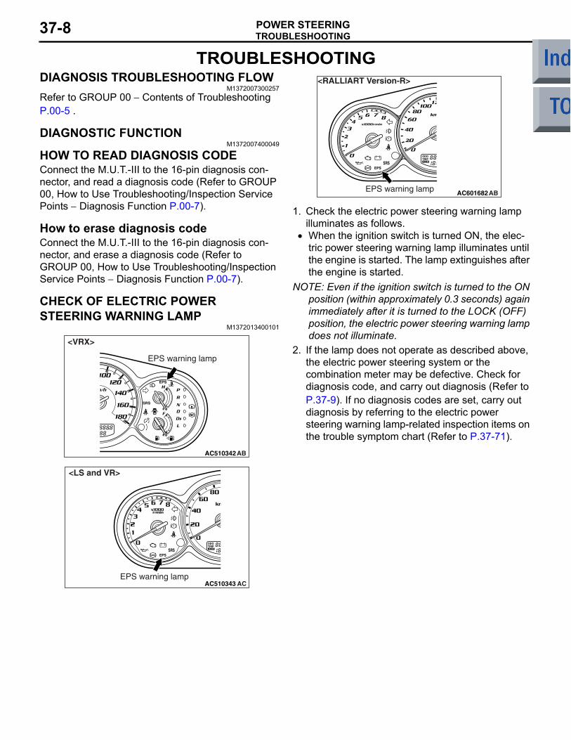
CHECK OF ELECTRIC POWER STEERING WARNING LAMP
M1372013400101
AC510342
EPS warning lamp
AB
<VRX>
AC510343EPS warning lamp
AC
<LS and VR>
AC601682EPS warning lamp AB
<RALLIART Version-R>
1. Check the electric power steering warning lamp illuminates as follows.
• When the ignition switch is turned ON, the elec-tric power steering warning lamp illuminates until the engine is started. The lamp extinguishes after the engine is started.
NOTE: Even if the ignition switch is turned to the ON position (within approximately 0.3 seconds) again immediately after it is turned to the LOCK (OFF) position, the electric power steering warning lamp does not illuminate.
2. If the lamp does not operate as described above, the electric power steering system or the combination meter may be defective. Check for diagnosis code, and carry out diagnosis (Refer to P.37-9). If no diagnosis codes are set, carry out diagnosis by referring to the electric power steering warning lamp-related inspection items on the trouble symptom chart (Refer to P.37-71).
TROUBLESHOOTINGPOWER STEERING 37-9
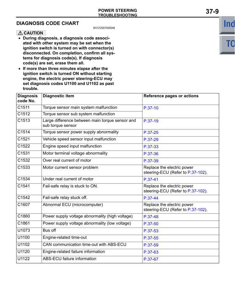
DIAGNOSIS CODE CHARTM1372007500046
CAUTION• During diagnosis, a diagnosis code associ-
ated with other system may be set when the ignition switch is turned on with connector(s) disconnected. On completion, confirm all sys-tems for diagnosis code(s). If diagnosis code(s) are set, erase them all.
•
Diagnosis code No.
Diagnostic item Reference pages or actions
C1511 Torque sensor main system malfunction P.37-10C1512 Torque sensor sub system malfunctionC1513 Large difference between main torque sensor and
sub torque sensorP.37-19
C1514 Torque sensor power supply abnormality P.37-25C1521 Vehicle speed sensor input malfunction P.37-29C1522 Engine speed input malfunction P.37-33C1531 Motor terminal voltage abnormality P.37-36C1532 Over real current of motor P.37-39C1533 Motor current sensor problem Replace the electric power
steering-ECU (Refer to P.37-102).C1534 Under real current of motor P.37-41C1541 Fail-safe relay is stuck to ON. Replace the electric power
steering-ECU (Refer to P.37-102).C1542 Fail-safe relay stuck off. P.37-44C1607 Abnormal ECU (microcomputer) Replace the electric power
steering-ECU (Refer to P.37-102).C1860 Power supply voltage abnormality (high voltage) P.37-48C1861 Power supply voltage abnormality (low voltage) P.37-50U1073 Bus off P.37-53U1100 Engine-related time-out P.37-55U1102 CAN communication time-out with ABS-ECU P.37-59U1120 Engine-related failure information P.37-63U1122 ABS-ECU failure information P.37-67
If more than three minutes elapse after the ignition switch is turned ON without starting engine, the electric power steering-ECU may set diagnosis codes U1100 and U1102 as past trouble.
TROUBLESHOOTINGPOWER STEERING37-10
DIAGNOSTIC TROUBLE CODE PROCEDURES
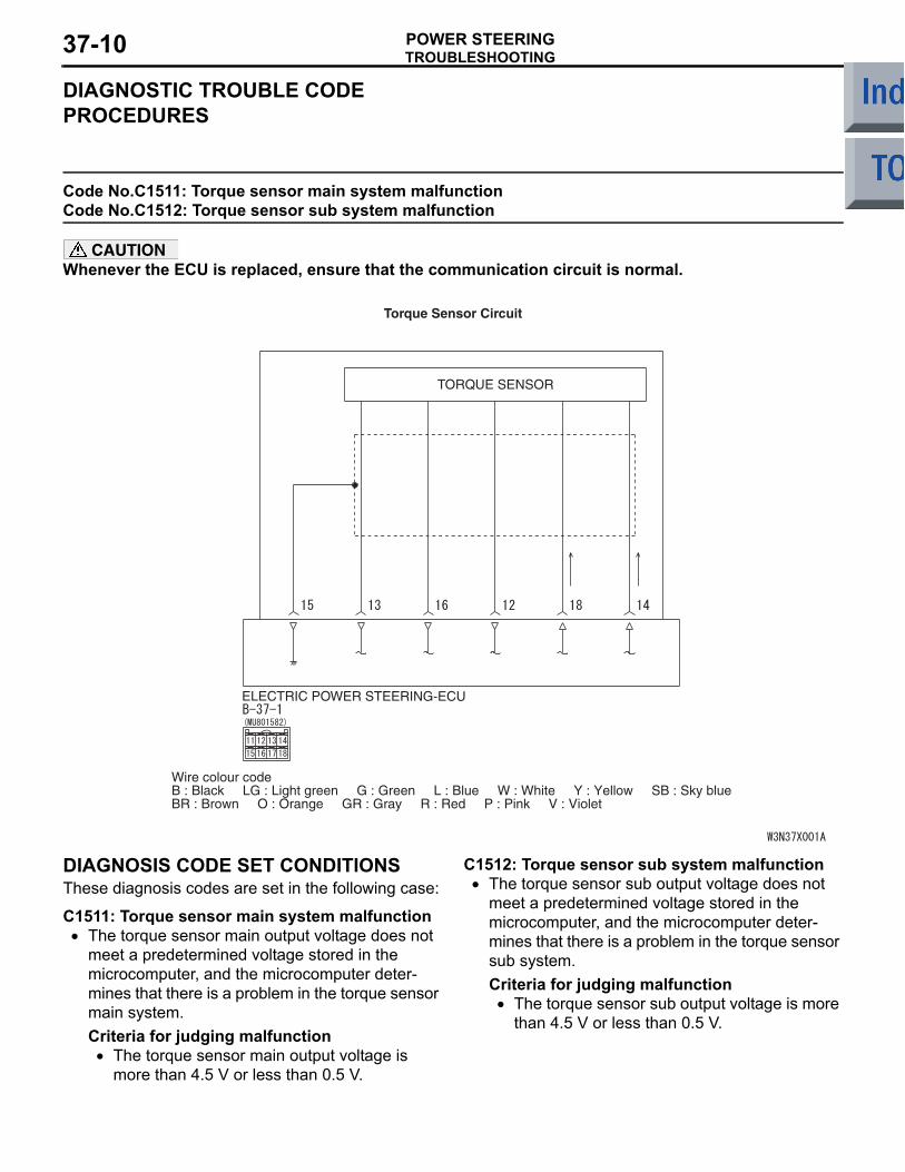
Code No.C1511: Torque sensor main system malfunction Code No.C1512: Torque sensor sub system malfunction
CAUTIONWhenever the ECU is replaced, ensure that the communication circuit is normal.
ELECTRIC POWER STEERING-ECU
TORQUE SENSOR
Wire colour codeB : Black LG : Light green G : Green L : Blue W : White Y : Yellow SB : Sky blueBR : Brown O : Orange GR : Gray R : Red P : Pink V : Violet
Torque Sensor Circuit
DIAGNOSIS CODE SET CONDITIONSThese diagnosis codes are set in the following case:
C1511: Torque sensor main system malfunction• The torque sensor main output voltage does not
meet a predetermined voltage stored in the microcomputer, and the microcomputer deter-mines that there is a problem in the torque sensor main system.Criteria for judging malfunction
• The torque sensor main output voltage is more than 4.5 V or less than 0.5 V.
C1512: Torque sensor sub system malfunction• The torque sensor sub output voltage does not
meet a predetermined voltage stored in the microcomputer, and the microcomputer deter-mines that there is a problem in the torque sensor sub system.Criteria for judging malfunction
• The torque sensor sub output voltage is more than 4.5 V or less than 0.5 V.
TROUBLESHOOTINGPOWER STEERING 37-11
PROBABLE CAUSESC1511: Torque sensor main system malfunction
• Defective harness wire(s) or connector(s)• Defective torque sensor of the steering gear and
linkage assembly• Malfunction of the electric power steering-ECU
C1512: Torque sensor sub system malfunction• Defective harness wire(s) or connector(s)• Defective torque sensor of the steering gear and
linkage assembly• Malfunction of the electric power steering-ECU
DIAGNOSIS PROCEDURE
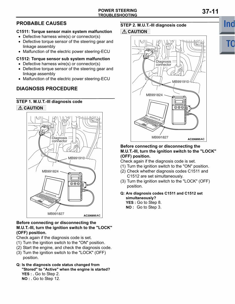
STEP 1. M.U.T.-III diagnosis code
AC206895AC
Diagnosisconnector
MB991827
MB991824
MB991910
CAUTION
Before connecting or disconnecting the M.U.T.-III, turn the ignition switch to the "LOCK" (OFF) position.Check again if the diagnosis code is set.(1) Turn the ignition switch to the "ON" position.(2) Start the engine, and check the diagnosis code.(3) Turn the ignition switch to the "LOCK" (OFF)
position.
Q: Is the diagnosis code status changed from "Stored" to "Active" when the engine is started?YES : . Go to Step 2.NO : . Go to Step 12.
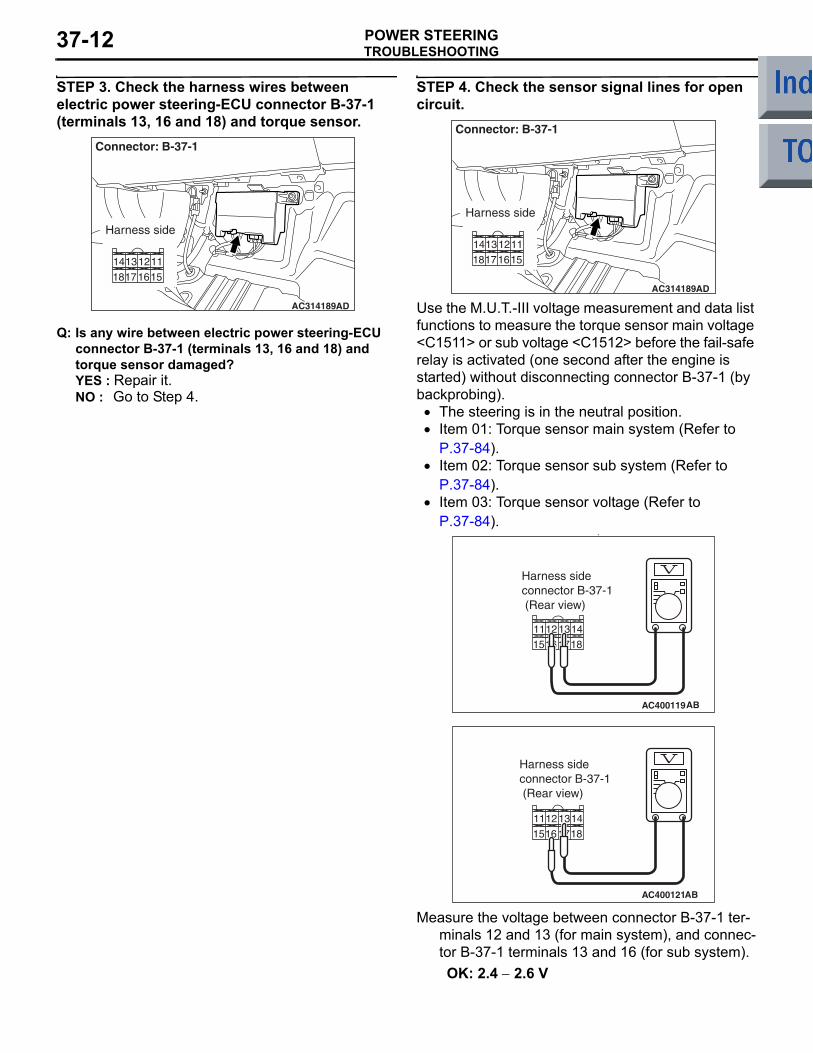
STEP 2. M.U.T.-III diagnosis code
AC206895AC
Diagnosisconnector
MB991827
MB991824
MB991910
CAUTION
Before connecting or disconnecting the M.U.T.-III, turn the ignition switch to the "LOCK" (OFF) position.Check again if the diagnosis code is set.(1) Turn the ignition switch to the "ON" position.(2) Check whether diagnosis codes C1511 and
C1512 are set simultaneously.(3) Turn the ignition switch to the "LOCK" (OFF)
position.
Q: Are diagnosis codes C1511 and C1512 set simultaneously?YES : Go to Step 8.NO : Go to Step 3.
TROUBLESHOOTINGPOWER STEERING37-12
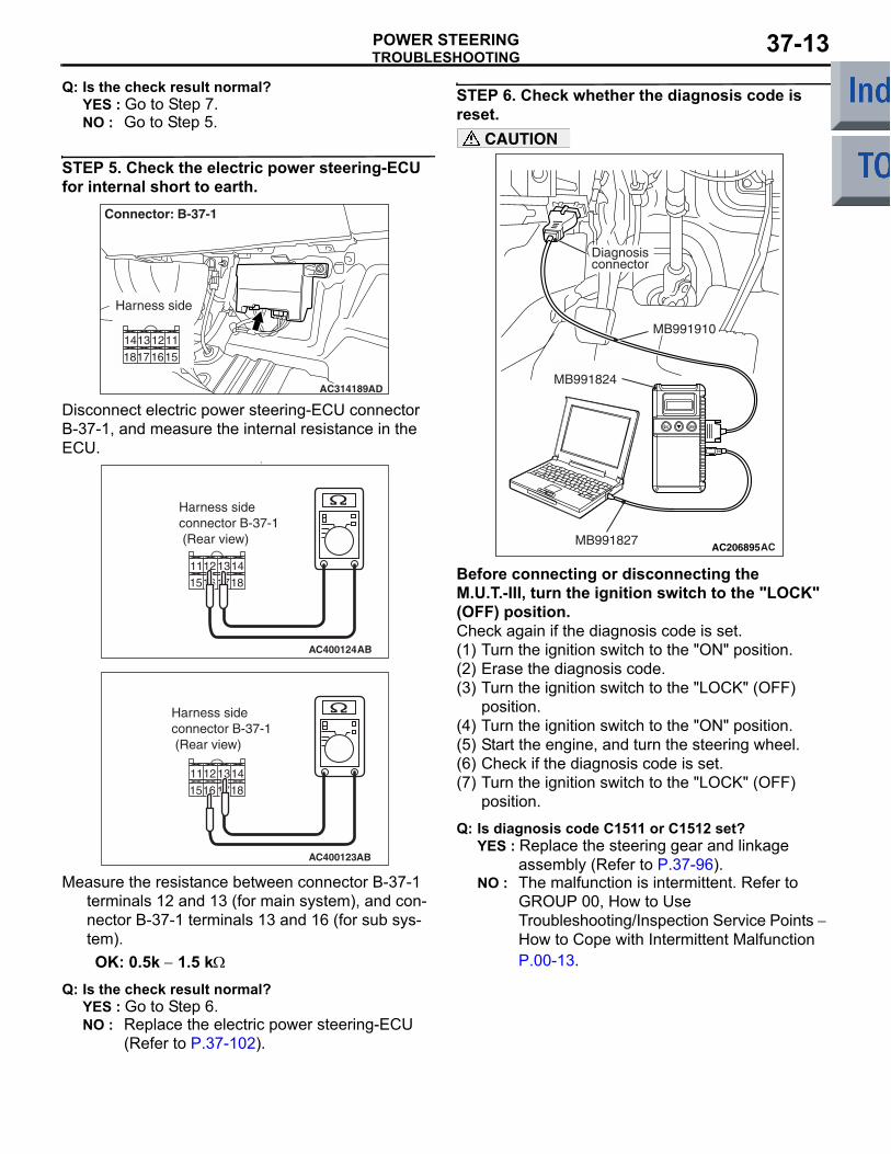
STEP 3. Check the harness wires between electric power steering-ECU connector B-37-1 (terminals 13, 16 and 18) and torque sensor.
AC314189AD
Connector: B-37-1
Harness side
Q: Is any wire between electric power steering-ECU connector B-37-1 (terminals 13, 16 and 18) and torque sensor damaged?YES : Repair it.NO : Go to Step 4.
STEP 4. Check the sensor signal lines for open circuit.
AC314189AD
Connector: B-37-1
Harness side
Use the M.U.T.-III voltage measurement and data list functions to measure the torque sensor main voltage <C1511> or sub voltage <C1512> before the fail-safe relay is activated (one second after the engine is started) without disconnecting connector B-37-1 (by backprobing).
• The steering is in the neutral position.• Item 01: Torque sensor main system (Refer to
P.37-84).• Item 02: Torque sensor sub system (Refer to
P.37-84).• Item 03: Torque sensor voltage (Refer to
P.37-84).•
AC400119
Harness sideconnector B-37-1 (Rear view)
AB
AC400121
Harness sideconnector B-37-1 (Rear view)
AB
Measure the voltage between connector B-37-1 ter-minals 12 and 13 (for main system), and connec-tor B-37-1 terminals 13 and 16 (for sub system).OK: 2.4 − 2.6 V
TROUBLESHOOTINGPOWER STEERING 37-13
Q: Is the check result normal?YES : Go to Step 7.NO : Go to Step 5.
STEP 5. Check the electric power steering-ECU for internal short to earth.
AC314189AD
Connector: B-37-1
Harness side
Disconnect electric power steering-ECU connector B-37-1, and measure the internal resistance in the ECU.
•
AC400124
Harness sideconnector B-37-1 (Rear view)
AB
AC400123
14
18
13
17
12
16
11
15
Harness sideconnector B-37-1 (Rear view)
AB
Measure the resistance between connector B-37-1 terminals 12 and 13 (for main system), and con-nector B-37-1 terminals 13 and 16 (for sub sys-tem).OK: 0.5k − 1.5 kΩ
Q: Is the check result normal?YES : Go to Step 6.NO : Replace the electric power steering-ECU
(Refer to P.37-102).
STEP 6. Check whether the diagnosis code is reset.
AC206895AC
Diagnosisconnector
MB991827
MB991824
MB991910
CAUTION
Before connecting or disconnecting the M.U.T.-III, turn the ignition switch to the "LOCK" (OFF) position.Check again if the diagnosis code is set.(1) Turn the ignition switch to the "ON" position.(2) Erase the diagnosis code.(3) Turn the ignition switch to the "LOCK" (OFF)
position.(4) Turn the ignition switch to the "ON" position.(5) Start the engine, and turn the steering wheel.(6) Check if the diagnosis code is set.(7) Turn the ignition switch to the "LOCK" (OFF)
position.
Q: Is diagnosis code C1511 or C1512 set?YES : Replace the steering gear and linkage
assembly (Refer to P.37-96).NO : The malfunction is intermittent. Refer to
GROUP 00, How to Use Troubleshooting/Inspection Service Points − How to Cope with Intermittent Malfunction P.00-13.
TROUBLESHOOTINGPOWER STEERING37-14
STEP 7. Check whether the diagnosis code is reset.
AC206895AC
Diagnosisconnector
MB991827
MB991824
MB991910
CAUTION
Before connecting or disconnecting the M.U.T.-III, turn the ignition switch to the "LOCK" (OFF) position.Check again if the diagnosis code is set.(1) Turn the ignition switch to the "ON" position.(2) Erase the diagnosis code.(3) Turn the ignition switch to the "LOCK" (OFF)
position.(4) Turn the ignition switch to the "ON" position.(5) Start the engine, and turn the steering wheel.(6) Check if the diagnosis code is set.(7) Turn the ignition switch to the "LOCK" (OFF)
position.
Q: Is diagnosis code C1511 or C1512 set?YES : . Replace the electric power steering-ECU
(Refer to P.37-102). NO : . The malfunction is intermittent. Refer to
GROUP 00, How to Use Troubleshooting/Inspection Service Points − How to Cope with Intermittent Malfunction P.00-13.
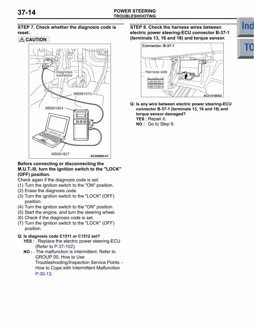
STEP 8. Check the harness wires between electric power steering-ECU connector B-37-1 (terminals 13, 16 and 18) and torque sensor.
AC314189AD
Connector: B-37-1
Harness side
Q: Is any wire between electric power steering-ECU connector B-37-1 (terminals 13, 16 and 18) and torque sensor damaged?YES : Repair it.NO : Go to Step 9.
TROUBLESHOOTINGPOWER STEERING 37-15
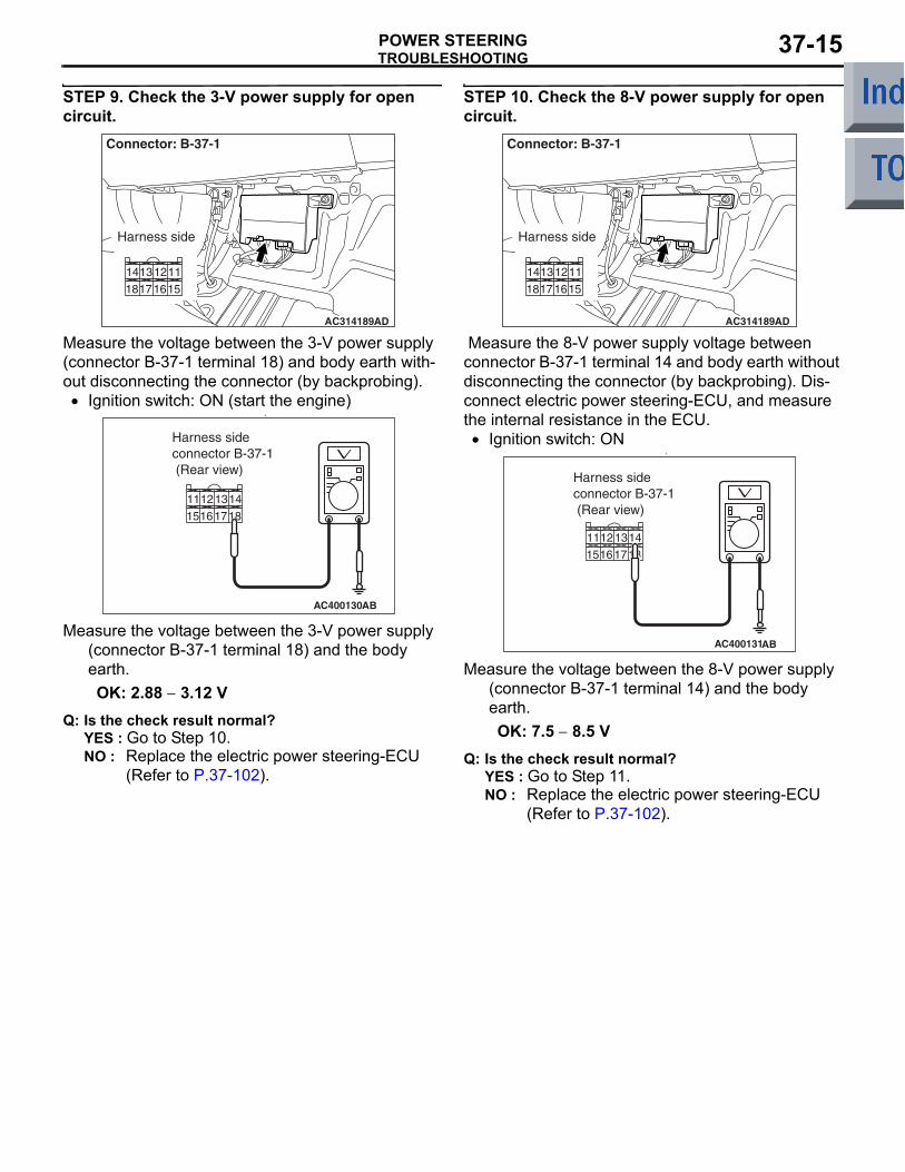
STEP 9. Check the 3-V power supply for open circuit.
AC314189AD
Connector: B-37-1
Harness side
Measure the voltage between the 3-V power supply (connector B-37-1 terminal 18) and body earth with-out disconnecting the connector (by backprobing).
• Ignition switch: ON (start the engine)•
AC400130
Harness sideconnector B-37-1 (Rear view)
AB
Measure the voltage between the 3-V power supply (connector B-37-1 terminal 18) and the body earth.OK: 2.88 − 3.12 V
Q: Is the check result normal?YES : Go to Step 10.NO : Replace the electric power steering-ECU
(Refer to P.37-102).
STEP 10. Check the 8-V power supply for open circuit.
AC314189AD
Connector: B-37-1
Harness side
Measure the 8-V power supply voltage between connector B-37-1 terminal 14 and body earth without disconnecting the connector (by backprobing). Dis-connect electric power steering-ECU, and measure the internal resistance in the ECU.
• Ignition switch: ON•
AC400131
Harness sideconnector B-37-1 (Rear view)
AB
Measure the voltage between the 8-V power supply (connector B-37-1 terminal 14) and the body earth.OK: 7.5 − 8.5 V
Q: Is the check result normal?YES : Go to Step 11.NO : Replace the electric power steering-ECU
(Refer to P.37-102).
TROUBLESHOOTINGPOWER STEERING37-16
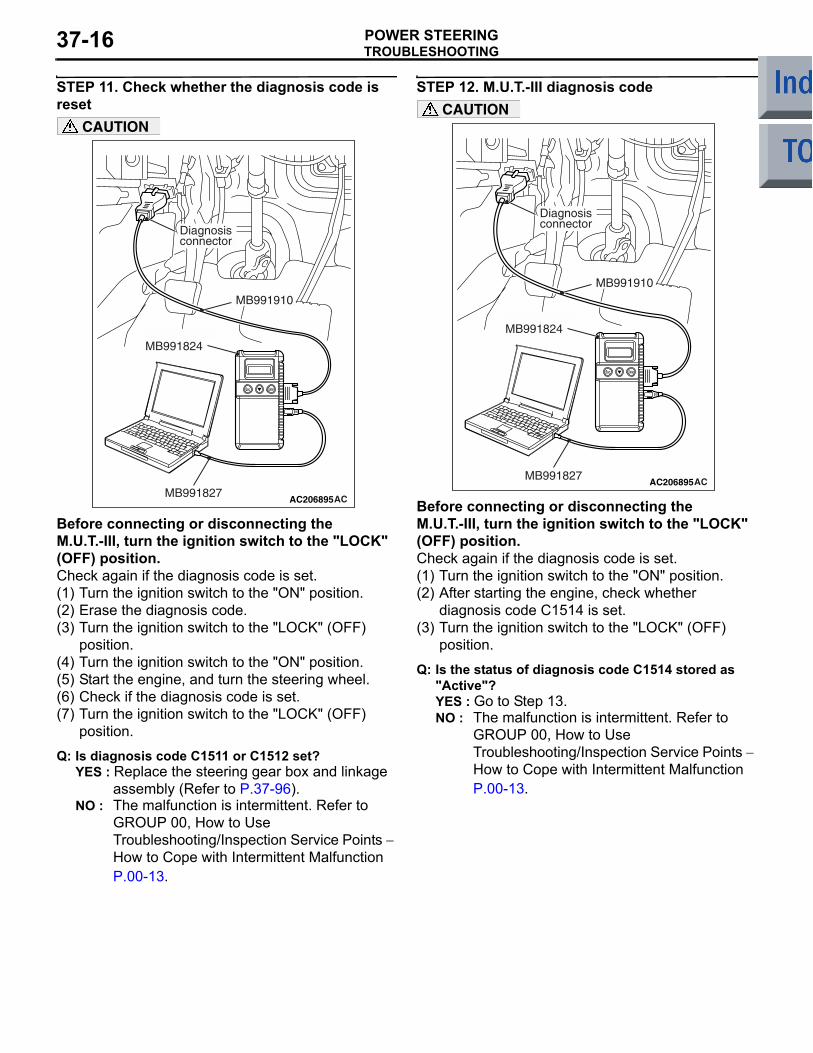
STEP 11. Check whether the diagnosis code is reset
AC206895AC
Diagnosisconnector
MB991827
MB991824
MB991910
CAUTION
Before connecting or disconnecting the M.U.T.-III, turn the ignition switch to the "LOCK" (OFF) position.Check again if the diagnosis code is set.(1) Turn the ignition switch to the "ON" position.(2) Erase the diagnosis code.(3) Turn the ignition switch to the "LOCK" (OFF)
position.(4) Turn the ignition switch to the "ON" position.(5) Start the engine, and turn the steering wheel.(6) Check if the diagnosis code is set.(7) Turn the ignition switch to the "LOCK" (OFF)
position.
Q: Is diagnosis code C1511 or C1512 set?YES : Replace the steering gear box and linkage
assembly (Refer to P.37-96).NO : The malfunction is intermittent. Refer to
GROUP 00, How to Use Troubleshooting/Inspection Service Points − How to Cope with Intermittent Malfunction P.00-13.
STEP 12. M.U.T.-III diagnosis code
AC206895AC
Diagnosisconnector
MB991827
MB991824
MB991910
CAUTION
Before connecting or disconnecting the M.U.T.-III, turn the ignition switch to the "LOCK" (OFF) position.Check again if the diagnosis code is set.(1) Turn the ignition switch to the "ON" position.(2) After starting the engine, check whether
diagnosis code C1514 is set.(3) Turn the ignition switch to the "LOCK" (OFF)
position.
Q: Is the status of diagnosis code C1514 stored as "Active"?YES : Go to Step 13.NO : The malfunction is intermittent. Refer to
GROUP 00, How to Use Troubleshooting/Inspection Service Points − How to Cope with Intermittent Malfunction P.00-13.
TROUBLESHOOTINGPOWER STEERING 37-17
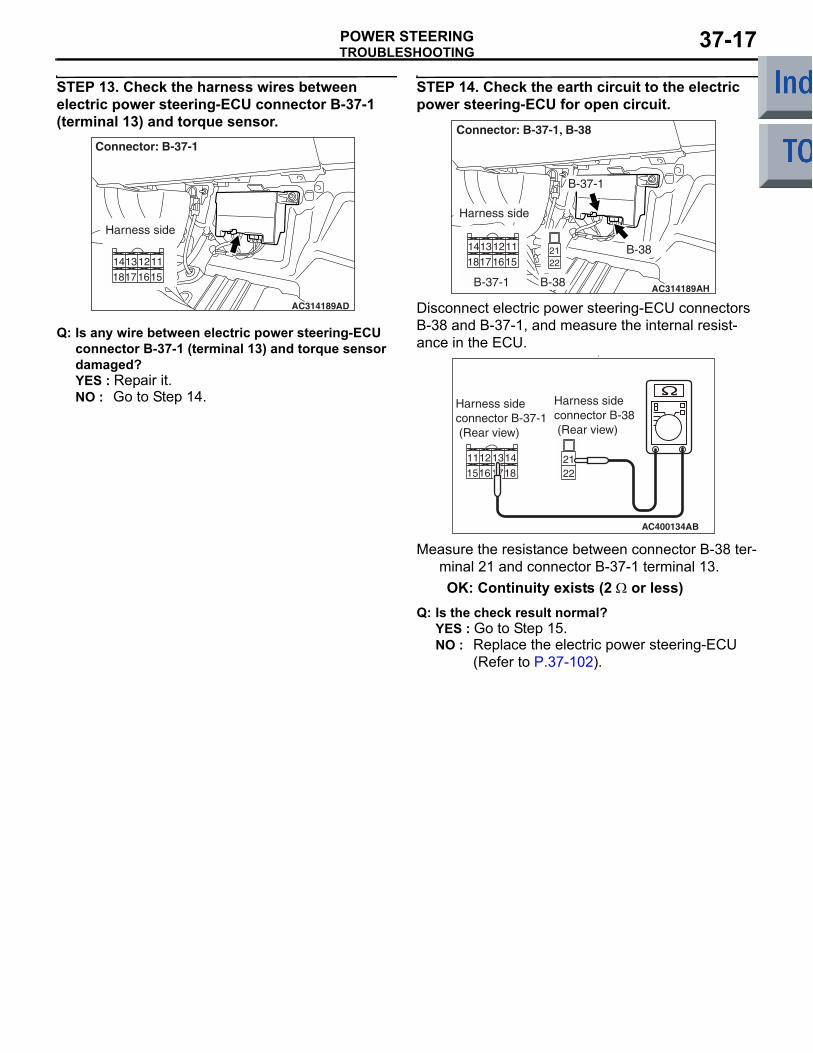
STEP 13. Check the harness wires between electric power steering-ECU connector B-37-1 (terminal 13) and torque sensor.
AC314189AD
Connector: B-37-1
Harness side
Q: Is any wire between electric power steering-ECU connector B-37-1 (terminal 13) and torque sensor damaged?YES : Repair it.NO : Go to Step 14.
STEP 14. Check the earth circuit to the electric power steering-ECU for open circuit.
AC314189AH
Connector: B-37-1, B-38
B-37-1
B-38
Harness side
B-37-1 B-38
Disconnect electric power steering-ECU connectors B-38 and B-37-1, and measure the internal resist-ance in the ECU.
•
AC400134
Harness sideconnector B-37-1 (Rear view)
AB
Harness sideconnector B-38 (Rear view)
Measure the resistance between connector B-38 ter-minal 21 and connector B-37-1 terminal 13.OK: Continuity exists (2 Ω or less)
Q: Is the check result normal?YES : Go to Step 15.NO : Replace the electric power steering-ECU
(Refer to P.37-102).
TROUBLESHOOTINGPOWER STEERING37-18
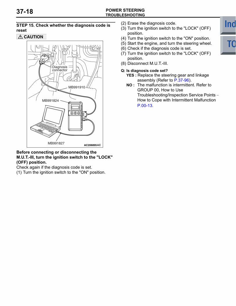
STEP 15. Check whether the diagnosis code is reset
AC206895AC
Diagnosisconnector
MB991827
MB991824
MB991910
CAUTION
Before connecting or disconnecting the M.U.T.-III, turn the ignition switch to the "LOCK" (OFF) position.Check again if the diagnosis code is set.(1) Turn the ignition switch to the "ON" position.
(2) Erase the diagnosis code.(3) Turn the ignition switch to the "LOCK" (OFF)
position.(4) Turn the ignition switch to the "ON" position.(5) Start the engine, and turn the steering wheel.(6) Check if the diagnosis code is set.(7) Turn the ignition switch to the "LOCK" (OFF)
position.(8) Disconnect M.U.T.-III.
Q: Is diagnosis code set?YES : Replace the steering gear and linkage
assembly (Refer to P.37-96).NO : The malfunction is intermittent. Refer to
GROUP 00, How to Use Troubleshooting/Inspection Service Points − How to Cope with Intermittent Malfunction P.00-13.
TROUBLESHOOTINGPOWER STEERING 37-19
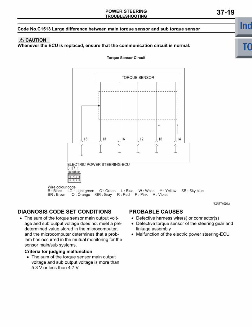
Code No.C1513 Large difference between main torque sensor and sub torque sensor
CAUTIONWhenever the ECU is replaced, ensure that the communication circuit is normal.
ELECTRIC POWER STEERING-ECU
TORQUE SENSOR
Wire colour codeB : Black LG : Light green G : Green L : Blue W : White Y : Yellow SB : Sky blueBR : Brown O : Orange GR : Gray R : Red P : Pink V : Violet
Torque Sensor Circuit
DIAGNOSIS CODE SET CONDITIONS• The sum of the torque sensor main output volt-
age and sub output voltage does not meet a pre-determined value stored in the microcomputer, and the microcomputer determines that a prob-lem has occurred in the mutual monitoring for the sensor main/sub systems.Criteria for judging malfunction
• The sum of the torque sensor main output voltage and sub output voltage is more than 5.3 V or less than 4.7 V.
PROBABLE CAUSES• Defective harness wire(s) or connector(s)• Defective torque sensor of the steering gear and
linkage assembly• Malfunction of the electric power steering-ECU
TROUBLESHOOTINGPOWER STEERING37-20
DIAGNOSTIC PROCEDURE
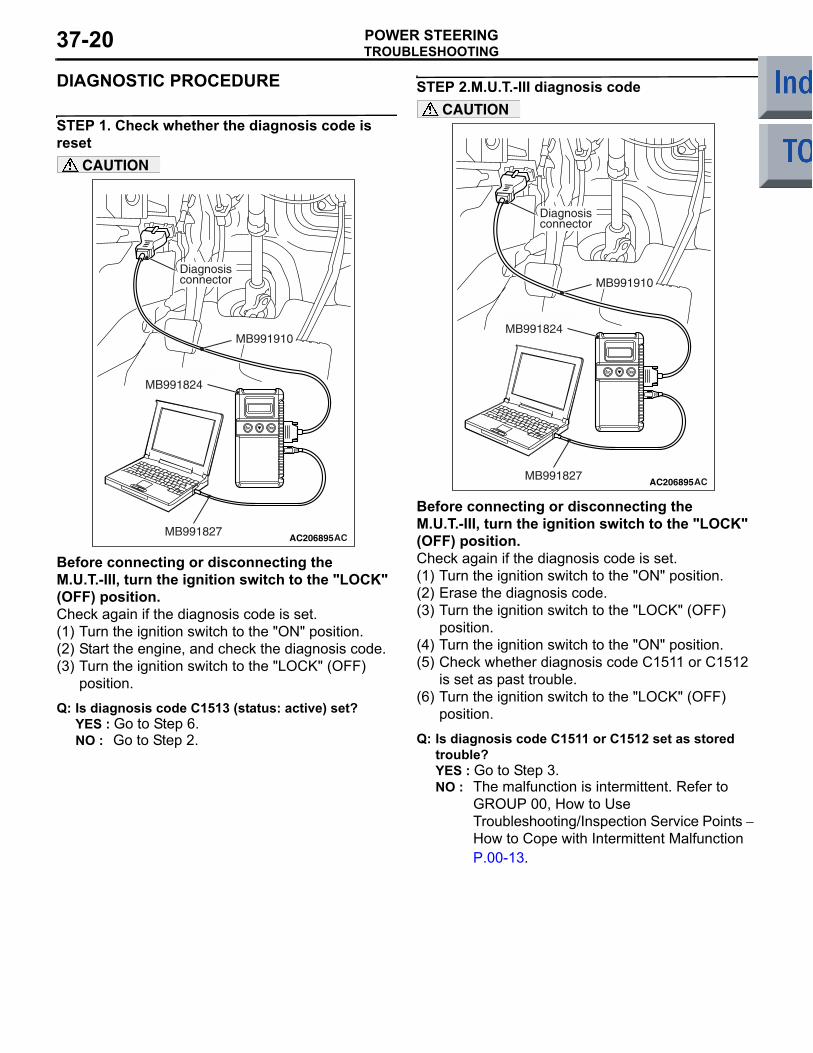
STEP 1. Check whether the diagnosis code is reset
AC206895AC
Diagnosisconnector
MB991827
MB991824
MB991910
CAUTION
Before connecting or disconnecting the M.U.T.-III, turn the ignition switch to the "LOCK" (OFF) position.Check again if the diagnosis code is set.(1) Turn the ignition switch to the "ON" position.(2) Start the engine, and check the diagnosis code.(3) Turn the ignition switch to the "LOCK" (OFF)
position.
Q: Is diagnosis code C1513 (status: active) set?YES : Go to Step 6.NO : Go to Step 2.
STEP 2.M.U.T.-III diagnosis code
AC206895AC
Diagnosisconnector
MB991827
MB991824
MB991910
CAUTION
Before connecting or disconnecting the M.U.T.-III, turn the ignition switch to the "LOCK" (OFF) position.Check again if the diagnosis code is set.(1) Turn the ignition switch to the "ON" position.(2) Erase the diagnosis code.(3) Turn the ignition switch to the "LOCK" (OFF)
position.(4) Turn the ignition switch to the "ON" position.(5) Check whether diagnosis code C1511 or C1512
is set as past trouble.(6) Turn the ignition switch to the "LOCK" (OFF)
position.
Q: Is diagnosis code C1511 or C1512 set as stored trouble?YES : Go to Step 3.NO : The malfunction is intermittent. Refer to
GROUP 00, How to Use Troubleshooting/Inspection Service Points − How to Cope with Intermittent Malfunction P.00-13.
TROUBLESHOOTINGPOWER STEERING 37-21
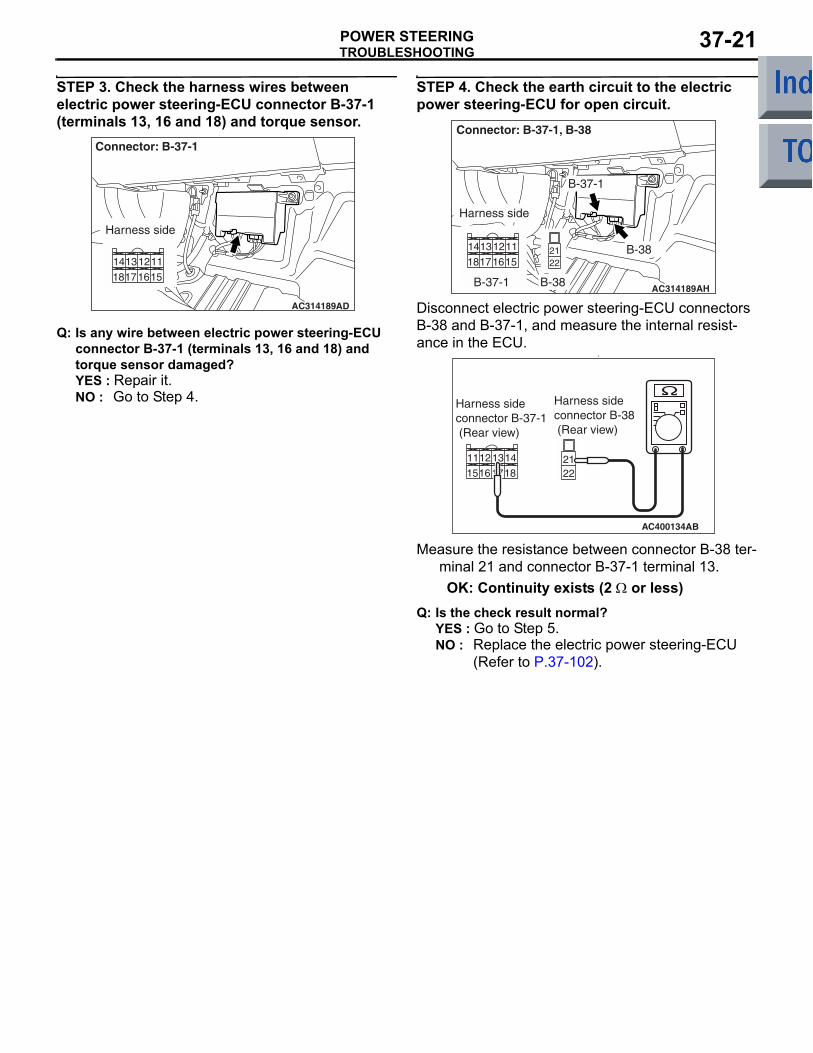
STEP 3. Check the harness wires between electric power steering-ECU connector B-37-1 (terminals 13, 16 and 18) and torque sensor.
AC314189AD
Connector: B-37-1
Harness side
Q: Is any wire between electric power steering-ECU connector B-37-1 (terminals 13, 16 and 18) and torque sensor damaged?YES : Repair it.NO : Go to Step 4.
STEP 4. Check the earth circuit to the electric power steering-ECU for open circuit.
AC314189AH
Connector: B-37-1, B-38
B-37-1
B-38
Harness side
B-37-1 B-38
Disconnect electric power steering-ECU connectors B-38 and B-37-1, and measure the internal resist-ance in the ECU.
•
AC400134
Harness sideconnector B-37-1 (Rear view)
AB
Harness sideconnector B-38 (Rear view)
Measure the resistance between connector B-38 ter-minal 21 and connector B-37-1 terminal 13.OK: Continuity exists (2 Ω or less)
Q: Is the check result normal?YES : Go to Step 5.NO : Replace the electric power steering-ECU
(Refer to P.37-102).
TROUBLESHOOTINGPOWER STEERING37-22
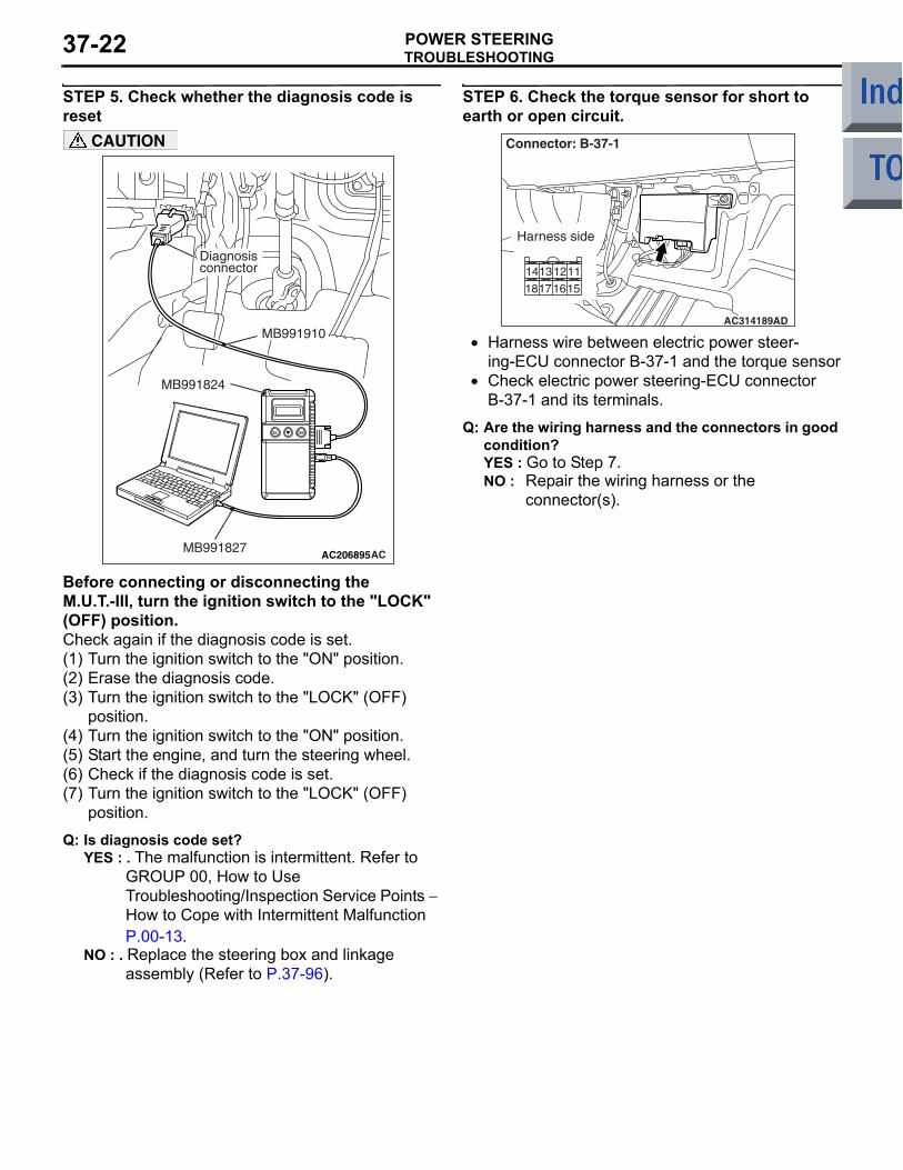
STEP 5. Check whether the diagnosis code is reset
AC206895AC
Diagnosisconnector
MB991827
MB991824
MB991910
CAUTION
Before connecting or disconnecting the M.U.T.-III, turn the ignition switch to the "LOCK" (OFF) position.Check again if the diagnosis code is set.(1) Turn the ignition switch to the "ON" position.(2) Erase the diagnosis code.(3) Turn the ignition switch to the "LOCK" (OFF)
position.(4) Turn the ignition switch to the "ON" position.(5) Start the engine, and turn the steering wheel.(6) Check if the diagnosis code is set.(7) Turn the ignition switch to the "LOCK" (OFF)
position.
Q: Is diagnosis code set?YES : . The malfunction is intermittent. Refer to
GROUP 00, How to Use Troubleshooting/Inspection Service Points − How to Cope with Intermittent Malfunction P.00-13.
NO : . Replace the steering box and linkage assembly (Refer to P.37-96).
STEP 6. Check the torque sensor for short to earth or open circuit.
AC314189AD
Connector: B-37-1
Harness side
• Harness wire between electric power steer-ing-ECU connector B-37-1 and the torque sensor
• Check electric power steering-ECU connector B-37-1 and its terminals.
Q: Are the wiring harness and the connectors in good condition?YES : Go to Step 7.NO : Repair the wiring harness or the
connector(s).
TROUBLESHOOTINGPOWER STEERING 37-23
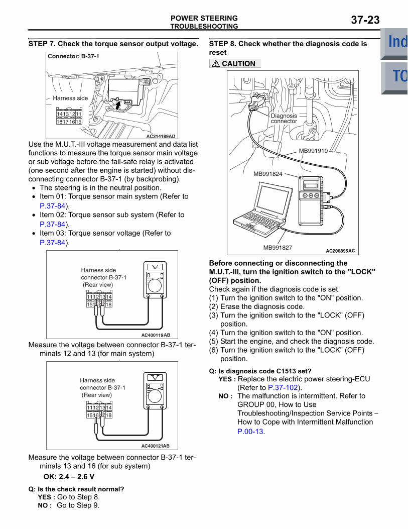
STEP 7. Check the torque sensor output voltage.
AC314189AD
Connector: B-37-1
Harness side
Use the M.U.T.-III voltage measurement and data list functions to measure the torque sensor main voltage or sub voltage before the fail-safe relay is activated (one second after the engine is started) without dis-connecting connector B-37-1 (by backprobing).
• The steering is in the neutral position.• Item 01: Torque sensor main system (Refer to
P.37-84).• Item 02: Torque sensor sub system (Refer to
P.37-84).• Item 03: Torque sensor voltage (Refer to
P.37-84).•
AC400119
Harness sideconnector B-37-1 (Rear view)
AB
Measure the voltage between connector B-37-1 ter-minals 12 and 13 (for main system)
•
AC400121
Harness sideconnector B-37-1 (Rear view)
AB
Measure the voltage between connector B-37-1 ter-minals 13 and 16 (for sub system)OK: 2.4 − 2.6 V
Q: Is the check result normal?YES : Go to Step 8.NO : Go to Step 9.
STEP 8. Check whether the diagnosis code is reset
AC206895AC
Diagnosisconnector
MB991827
MB991824
MB991910
CAUTION
Before connecting or disconnecting the M.U.T.-III, turn the ignition switch to the "LOCK" (OFF) position.Check again if the diagnosis code is set.(1) Turn the ignition switch to the "ON" position.(2) Erase the diagnosis code.(3) Turn the ignition switch to the "LOCK" (OFF)
position.(4) Turn the ignition switch to the "ON" position.(5) Start the engine, and check the diagnosis code.(6) Turn the ignition switch to the "LOCK" (OFF)
position.
Q: Is diagnosis code C1513 set?YES : Replace the electric power steering-ECU
(Refer to P.37-102).NO : The malfunction is intermittent. Refer to
GROUP 00, How to Use Troubleshooting/Inspection Service Points − How to Cope with Intermittent Malfunction P.00-13.
TROUBLESHOOTINGPOWER STEERING37-24
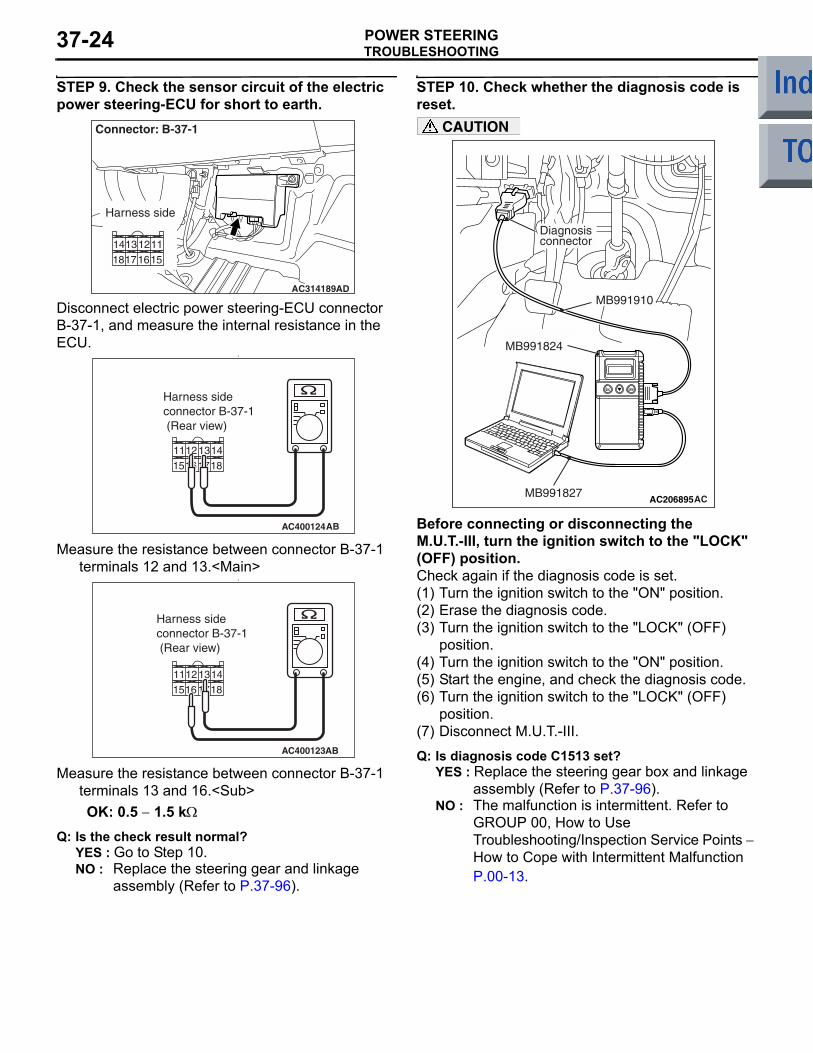
STEP 9. Check the sensor circuit of the electric power steering-ECU for short to earth.
AC314189AD
Connector: B-37-1
Harness side
Disconnect electric power steering-ECU connector B-37-1, and measure the internal resistance in the ECU.
•
AC400124
Harness sideconnector B-37-1 (Rear view)
AB
Measure the resistance between connector B-37-1 terminals 12 and 13.<Main>
•
AC400123
14
18
13
17
12
16
11
15
Harness sideconnector B-37-1 (Rear view)
AB
Measure the resistance between connector B-37-1 terminals 13 and 16.<Sub>OK: 0.5 − 1.5 kΩ
Q: Is the check result normal?YES : Go to Step 10.NO : Replace the steering gear and linkage
assembly (Refer to P.37-96).
STEP 10. Check whether the diagnosis code is reset.
AC206895AC
Diagnosisconnector
MB991827
MB991824
MB991910
CAUTION
Before connecting or disconnecting the M.U.T.-III, turn the ignition switch to the "LOCK" (OFF) position.Check again if the diagnosis code is set.(1) Turn the ignition switch to the "ON" position.(2) Erase the diagnosis code.(3) Turn the ignition switch to the "LOCK" (OFF)
position.(4) Turn the ignition switch to the "ON" position.(5) Start the engine, and check the diagnosis code.(6) Turn the ignition switch to the "LOCK" (OFF)
position.(7) Disconnect M.U.T.-III.
Q: Is diagnosis code C1513 set?YES : Replace the steering gear box and linkage
assembly (Refer to P.37-96).NO : The malfunction is intermittent. Refer to
GROUP 00, How to Use Troubleshooting/Inspection Service Points − How to Cope with Intermittent Malfunction P.00-13.
TROUBLESHOOTINGPOWER STEERING 37-25
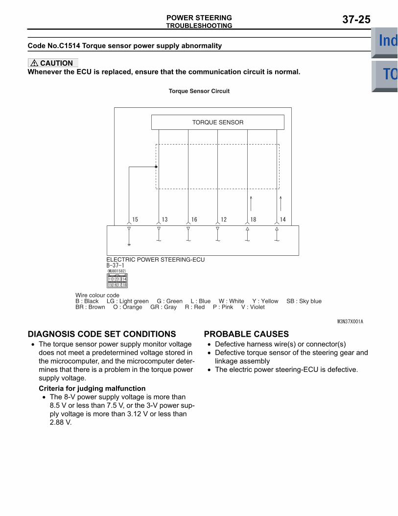
Code No.C1514 Torque sensor power supply abnormality
CAUTIONWhenever the ECU is replaced, ensure that the communication circuit is normal.
ELECTRIC POWER STEERING-ECU
TORQUE SENSOR
Wire colour codeB : Black LG : Light green G : Green L : Blue W : White Y : Yellow SB : Sky blueBR : Brown O : Orange GR : Gray R : Red P : Pink V : Violet
Torque Sensor Circuit
DIAGNOSIS CODE SET CONDITIONS• The torque sensor power supply monitor voltage
does not meet a predetermined voltage stored in the microcomputer, and the microcomputer deter-mines that there is a problem in the torque power supply voltage.Criteria for judging malfunction
• The 8-V power supply voltage is more than 8.5 V or less than 7.5 V, or the 3-V power sup-ply voltage is more than 3.12 V or less than 2.88 V.
PROBABLE CAUSES• Defective harness wire(s) or connector(s)• Defective torque sensor of the steering gear and
linkage assembly• The electric power steering-ECU is defective.
TROUBLESHOOTINGPOWER STEERING37-26
DIAGNOSTIC PROCEDURE
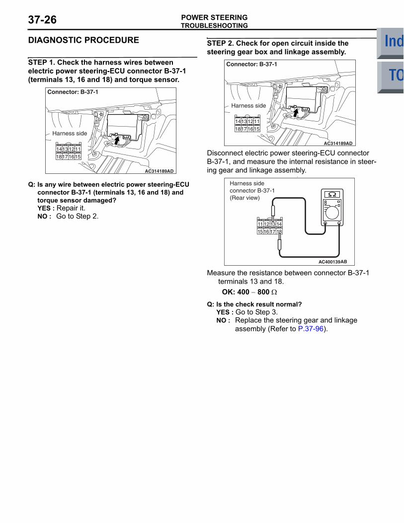
STEP 1. Check the harness wires between electric power steering-ECU connector B-37-1 (terminals 13, 16 and 18) and torque sensor.
AC314189AD
Connector: B-37-1
Harness side
Q: Is any wire between electric power steering-ECU connector B-37-1 (terminals 13, 16 and 18) and torque sensor damaged?YES : Repair it.NO : Go to Step 2.
STEP 2. Check for open circuit inside the steering gear box and linkage assembly.
AC314189AD
Connector: B-37-1
Harness side
Disconnect electric power steering-ECU connector B-37-1, and measure the internal resistance in steer-ing gear and linkage assembly.
•
AC400139AB
Harness sideconnector B-37-1(Rear view)
Measure the resistance between connector B-37-1 terminals 13 and 18.OK: 400 − 800 Ω
Q: Is the check result normal?YES : Go to Step 3.NO : Replace the steering gear and linkage
assembly (Refer to P.37-96).
TROUBLESHOOTINGPOWER STEERING 37-27
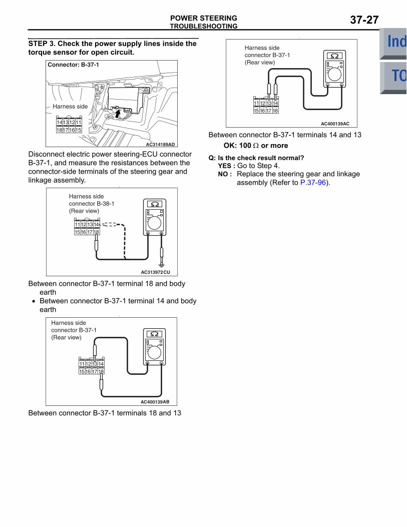
STEP 3. Check the power supply lines inside the torque sensor for open circuit.
AC314189AD
Connector: B-37-1
Harness side
Disconnect electric power steering-ECU connector B-37-1, and measure the resistances between the connector-side terminals of the steering gear and linkage assembly.
•
AC313972CU
Harness sideconnector B-38-1(Rear view)
Between connector B-37-1 terminal 18 and body earth
• Between connector B-37-1 terminal 14 and body earth
•
AC400139AB
Harness sideconnector B-37-1(Rear view)
Between connector B-37-1 terminals 18 and 13
•
AC400139AC
Harness sideconnector B-37-1(Rear view)
Between connector B-37-1 terminals 14 and 13OK: 100 Ω or more
Q: Is the check result normal?YES : Go to Step 4.NO : Replace the steering gear and linkage
assembly (Refer to P.37-96).
TROUBLESHOOTINGPOWER STEERING37-28
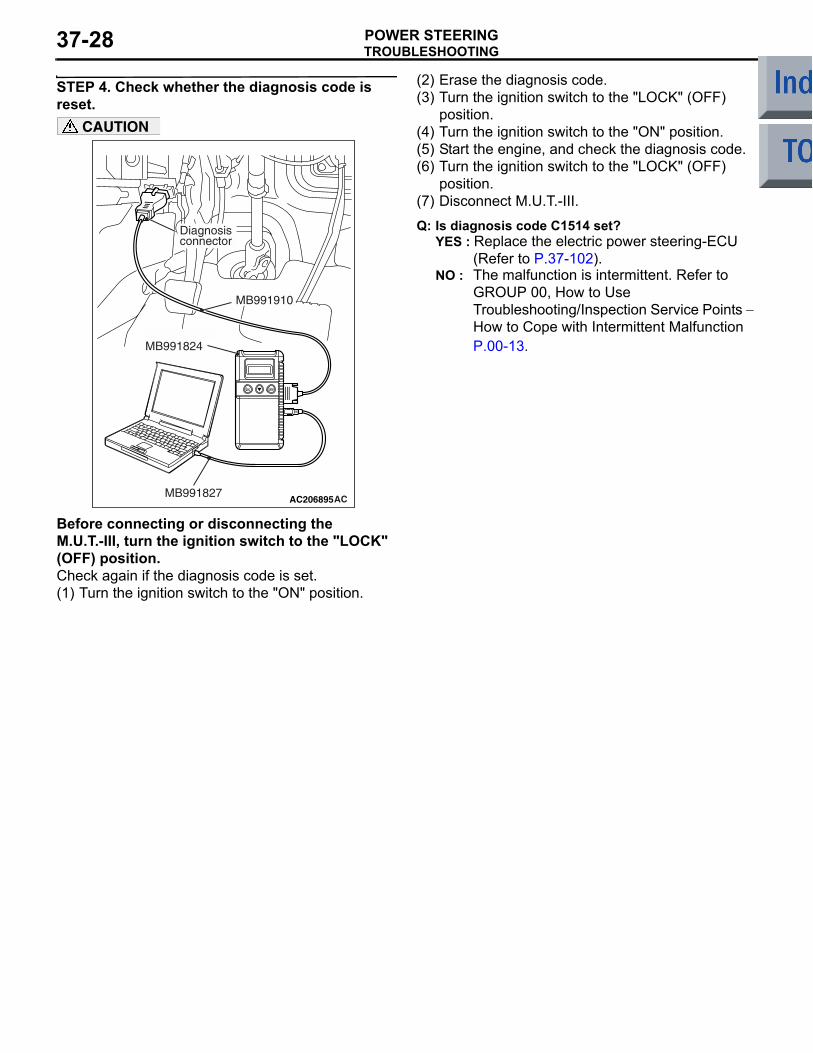
STEP 4. Check whether the diagnosis code is reset.
AC206895AC
Diagnosisconnector
MB991827
MB991824
MB991910
CAUTION
Before connecting or disconnecting the M.U.T.-III, turn the ignition switch to the "LOCK" (OFF) position.Check again if the diagnosis code is set.(1) Turn the ignition switch to the "ON" position.
(2) Erase the diagnosis code.(3) Turn the ignition switch to the "LOCK" (OFF)
position.(4) Turn the ignition switch to the "ON" position.(5) Start the engine, and check the diagnosis code.(6) Turn the ignition switch to the "LOCK" (OFF)
position.(7) Disconnect M.U.T.-III.
Q: Is diagnosis code C1514 set?YES : Replace the electric power steering-ECU
(Refer to P.37-102). NO : The malfunction is intermittent. Refer to
GROUP 00, How to Use Troubleshooting/Inspection Service Points − How to Cope with Intermittent Malfunction P.00-13.
TROUBLESHOOTINGPOWER STEERING 37-29
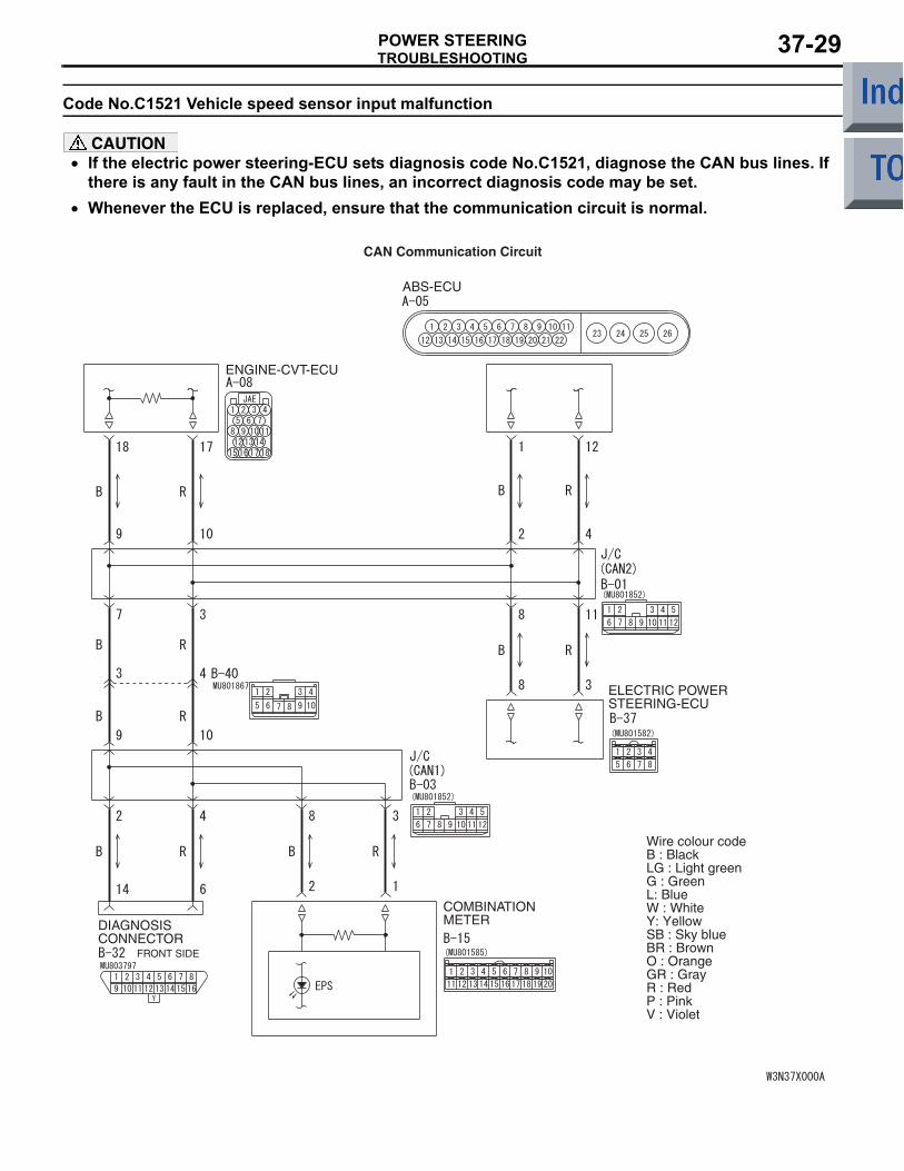
Code No.C1521 Vehicle speed sensor input malfunction
CAUTION• If the electric power steering-ECU sets diagnosis code No.C1521, diagnose the CAN bus lines. If
there is any fault in the CAN bus lines, an incorrect diagnosis code may be set.•
ENGINE-CVT-ECU
DIAGNOSISCONNECTOR
FRONT SIDE
COMBINATIONMETER
ABS-ECU
CAN Communication Circuit
Wire colour codeB : BlackLG : Light greenG : GreenL: BlueW : WhiteY: YellowSB : Sky blueBR : BrownO : OrangeGR : GrayR : RedP : PinkV : Violet
ELECTRIC POWER STEERING-ECU
Whenever the ECU is replaced, ensure that the communication circuit is normal.
TROUBLESHOOTINGPOWER STEERING37-30
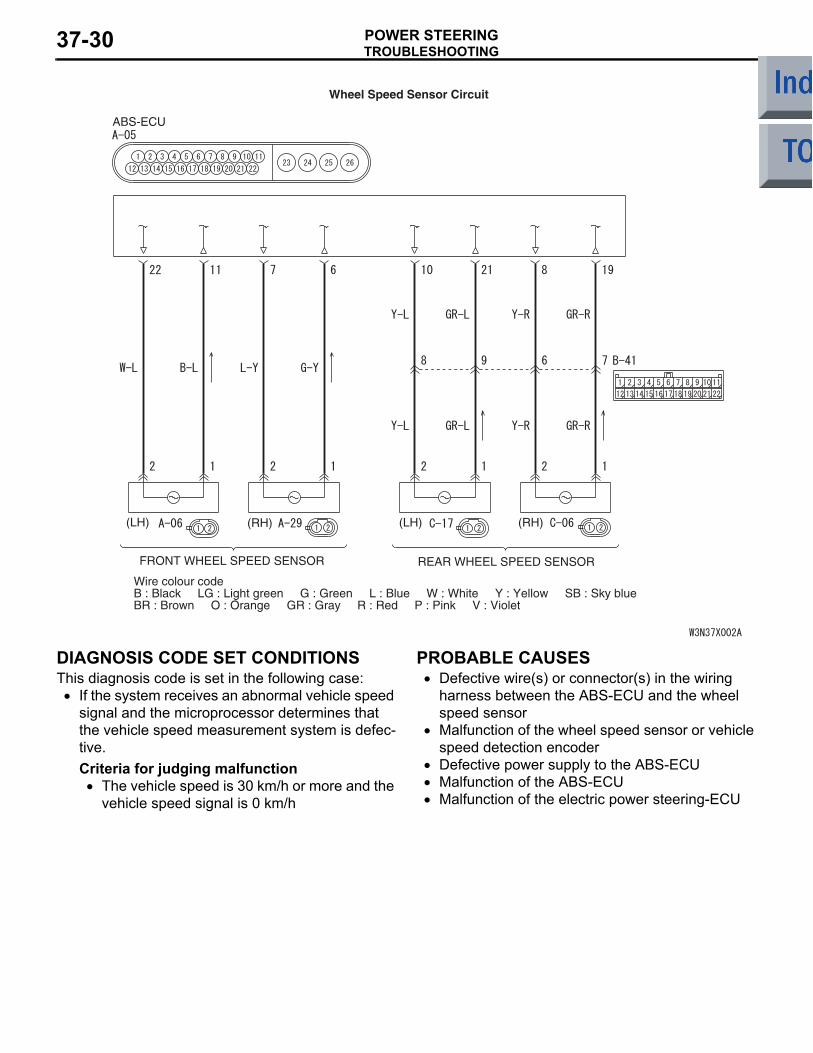
FRONT WHEEL SPEED SENSOR
(LH) (RH) (LH) (RH)
ABS-ECU
REAR WHEEL SPEED SENSOR
Wire colour codeB : Black LG : Light green G : Green L : Blue W : White Y : Yellow SB : Sky blueBR : Brown O : Orange GR : Gray R : Red P : Pink V : Violet
Wheel Speed Sensor Circuit
DIAGNOSIS CODE SET CONDITIONSThis diagnosis code is set in the following case:
• If the system receives an abnormal vehicle speed signal and the microprocessor determines that the vehicle speed measurement system is defec-tive. Criteria for judging malfunction
• The vehicle speed is 30 km/h or more and the vehicle speed signal is 0 km/h
PROBABLE CAUSES• Defective wire(s) or connector(s) in the wiring
harness between the ABS-ECU and the wheel speed sensor
• Malfunction of the wheel speed sensor or vehicle speed detection encoder
• Defective power supply to the ABS-ECU• Malfunction of the ABS-ECU• Malfunction of the electric power steering-ECU
TROUBLESHOOTINGPOWER STEERING 37-31
DIAGNOSIS PROCEDURE
STEP 1. M.U.T.-III CAN bus diagnostics
AC206895AC
Diagnosisconnector
MB991827
MB991824
MB991910
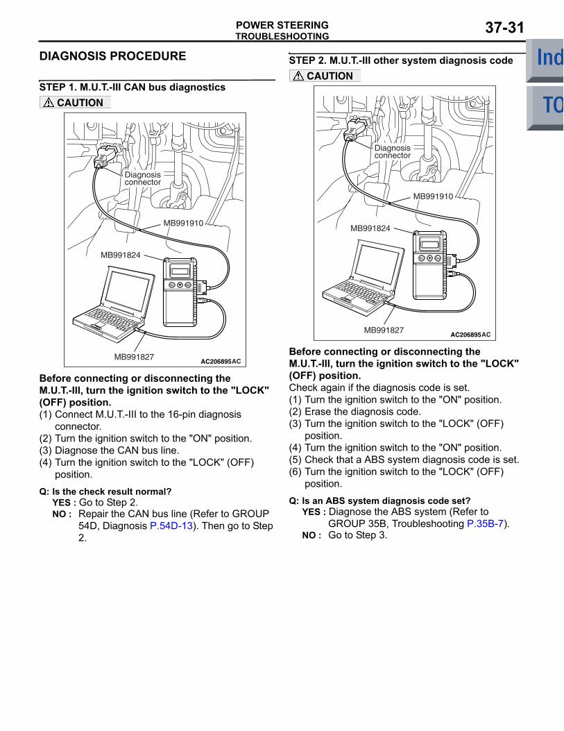
CAUTION
Before connecting or disconnecting the M.U.T.-III, turn the ignition switch to the "LOCK" (OFF) position.(1) Connect M.U.T.-III to the 16-pin diagnosis
connector.(2) Turn the ignition switch to the "ON" position.(3) Diagnose the CAN bus line.(4) Turn the ignition switch to the "LOCK" (OFF)
position.
Q: Is the check result normal?YES : Go to Step 2.NO : Repair the CAN bus line (Refer to GROUP
54D, Diagnosis P.54D-13). Then go to Step 2.
STEP 2. M.U.T.-III other system diagnosis code
AC206895AC
Diagnosisconnector
MB991827
MB991824
MB991910
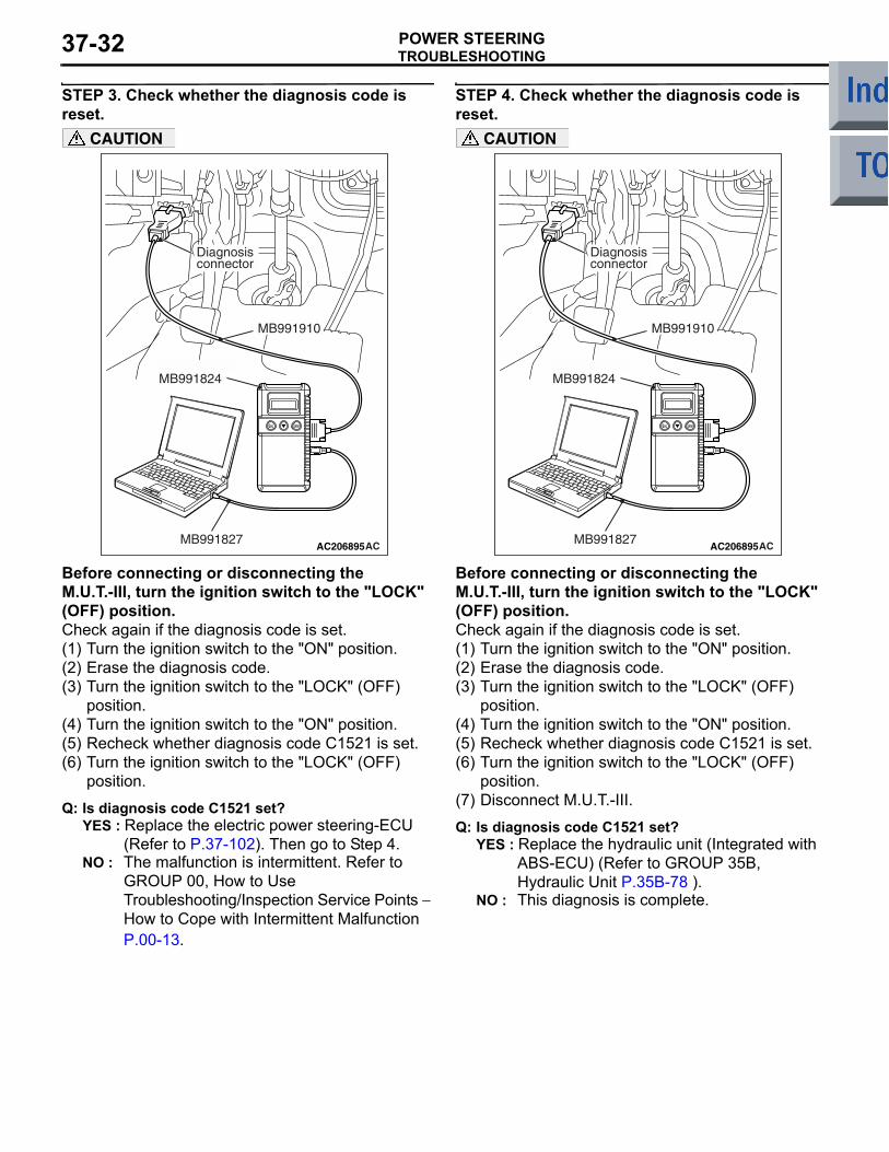
CAUTION
Before connecting or disconnecting the M.U.T.-III, turn the ignition switch to the "LOCK" (OFF) position.Check again if the diagnosis code is set.(1) Turn the ignition switch to the "ON" position.(2) Erase the diagnosis code.(3) Turn the ignition switch to the "LOCK" (OFF)
position.(4) Turn the ignition switch to the "ON" position.(5) Check that a ABS system diagnosis code is set.(6) Turn the ignition switch to the "LOCK" (OFF)
position.
Q: Is an ABS system diagnosis code set?YES : Diagnose the ABS system (Refer to
GROUP 35B, Troubleshooting P.35B-7).NO : Go to Step 3.
TROUBLESHOOTINGPOWER STEERING37-32
STEP 3. Check whether the diagnosis code is reset.
AC206895AC
Diagnosisconnector
MB991827
MB991824
MB991910
CAUTION
Before connecting or disconnecting the M.U.T.-III, turn the ignition switch to the "LOCK" (OFF) position.Check again if the diagnosis code is set.(1) Turn the ignition switch to the "ON" position.(2) Erase the diagnosis code.(3) Turn the ignition switch to the "LOCK" (OFF)
position.(4) Turn the ignition switch to the "ON" position.(5) Recheck whether diagnosis code C1521 is set.(6) Turn the ignition switch to the "LOCK" (OFF)
position.
Q: Is diagnosis code C1521 set?YES : Replace the electric power steering-ECU
(Refer to P.37-102). Then go to Step 4.NO : The malfunction is intermittent. Refer to
GROUP 00, How to Use Troubleshooting/Inspection Service Points − How to Cope with Intermittent Malfunction P.00-13.
STEP 4. Check whether the diagnosis code is reset.
AC206895AC
Diagnosisconnector
MB991827
MB991824
MB991910
CAUTION
Before connecting or disconnecting the M.U.T.-III, turn the ignition switch to the "LOCK" (OFF) position.Check again if the diagnosis code is set.(1) Turn the ignition switch to the "ON" position.(2) Erase the diagnosis code.(3) Turn the ignition switch to the "LOCK" (OFF)
position.(4) Turn the ignition switch to the "ON" position.(5) Recheck whether diagnosis code C1521 is set.(6) Turn the ignition switch to the "LOCK" (OFF)
position.(7) Disconnect M.U.T.-III.
Q: Is diagnosis code C1521 set?YES : Replace the hydraulic unit (Integrated with
ABS-ECU) (Refer to GROUP 35B, Hydraulic Unit P.35B-78 ).
NO : This diagnosis is complete.

TROUBLESHOOTINGPOWER STEERING 37-33
Code No.C1522 Engine speed input malfunction
CAUTION• If the electric power steering-ECU sets diagnosis code No.C1522, diagnose the CAN bus lines. If
there is any fault in the CAN bus lines, an incorrect diagnosis code may be set.•
ENGINE-CVT-ECU
DIAGNOSISCONNECTOR
FRONT SIDE
COMBINATIONMETER
ABS-ECU
EPS-ECU
Wire colour codeB : BlackLG : Light greenG : GreenL: BlueW : WhiteY: YellowSB : Sky blueBR : BrownO : OrangeGR : GreyR : RedP : PinkV : VioletPU: Purple
CAN Communication Circuit
Whenever the ECU is replaced, ensure that the communication circuit is normal.
TROUBLESHOOTINGPOWER STEERING37-34
DIAGNOSIS CODE SET CONDITIONS• If the system receives an abnormal engine speed
signal and the microprocessor determines that the engine speed measurement system is defec-tive. Criteria for judging malfunction
• When the vehicle maintains the vehicle speed of 15 km/h or above and the engine speed signal stays 0 rpm for 60 seconds
PROBABLE CAUSES• Defective wire(s) or connector(s) in the crank-
shaft angle sensor input circuit of the engine-CVT-ECU
• Malfunction of the engine-CVT-ECU• Malfunction of the electric power steering-ECU• The vehicle kept running with the engine stopped
for 60 seconds or more.
DIAGNOSIS PROCEDURE
STEP 1. M.U.T.-III CAN bus diagnostics
AC206895AC
Diagnosisconnector
MB991827
MB991824
MB991910
CAUTION
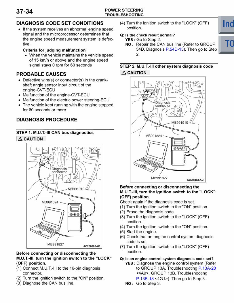
Before connecting or disconnecting the M.U.T.-III, turn the ignition switch to the "LOCK" (OFF) position.(1) Connect M.U.T.-III to the 16-pin diagnosis
connector.(2) Turn the ignition switch to the "ON" position.(3) Diagnose the CAN bus line.
(4) Turn the ignition switch to the "LOCK" (OFF) position.
Q: Is the check result normal?YES : Go to Step 2.NO : Repair the CAN bus line (Refer to GROUP
54D, Diagnosis P.54D-13). Then go to Step 2.
STEP 2. M.U.T.-III other system diagnosis code
AC206895AC
Diagnosisconnector
MB991827
MB991824
MB991910
CAUTION
Before connecting or disconnecting the M.U.T.-III, turn the ignition switch to the "LOCK" (OFF) position.Check again if the diagnosis code is set.(1) Turn the ignition switch to the "ON" position.(2) Erase the diagnosis code.(3) Turn the ignition switch to the "LOCK" (OFF)
position.(4) Turn the ignition switch to the "ON" position.(5) Start the engine.(6) Check that an engine control system diagnosis
code is set.(7) Turn the ignition switch to the "LOCK" (OFF)
position.
Q: Is an engine control system diagnosis code set?YES : Diagnose the engine control system (Refer
to GROUP 13A, Troubleshooting P.13A-20 <4A9>, GROUP 13B, Troubleshooting P.13B-18 <4G1>). Then go to Step 3.
NO : Go to Step 3.
TROUBLESHOOTINGPOWER STEERING 37-35
STEP 3. M.U.T.-III data list
AC206895AC
Diagnosisconnector
MB991827
MB991824
MB991910
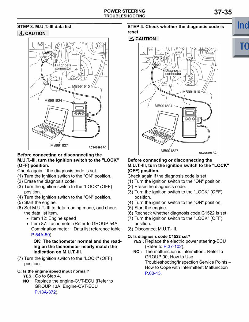
CAUTION
Before connecting or disconnecting the M.U.T.-III, turn the ignition switch to the "LOCK" (OFF) position.Check again if the diagnosis code is set.(1) Turn the ignition switch to the "ON" position.(2) Erase the diagnosis code.(3) Turn the ignition switch to the "LOCK" (OFF)
position.(4) Turn the ignition switch to the "ON" position.(5) Start the engine.(6) Set M.U.T.-III to data reading mode, and check
the data list item.• Item 12: Engine speed• Item 87: Tachometer (Refer to GROUP 54A,
Combination meter − Data list reference table P.54A-59)OK: The tachometer normal and the read-ing on the tachometer nearly match the indication on M.U.T.-III.
(7) Turn the ignition switch to the "LOCK" (OFF) position.
Q: Is the engine speed input normal?YES : Go to Step 4.NO : Replace the engine-CVT-ECU (Refer to
GROUP 13A, Engine-CVT-ECU P.13A-372).
STEP 4. Check whether the diagnosis code is reset.
AC206895AC
Diagnosisconnector
MB991827
MB991824
MB991910
CAUTION
Before connecting or disconnecting the M.U.T.-III, turn the ignition switch to the "LOCK" (OFF) position.Check again if the diagnosis code is set.(1) Turn the ignition switch to the "ON" position.(2) Erase the diagnosis code.(3) Turn the ignition switch to the "LOCK" (OFF)
position.(4) Turn the ignition switch to the "ON" position.(5) Start the engine.(6) Recheck whether diagnosis code C1522 is set.(7) Turn the ignition switch to the "LOCK" (OFF)
position.(8) Disconnect M.U.T.-III.
Q: Is diagnosis code C1522 set?YES : Replace the electric power steering-ECU
(Refer to P.37-102).NO : The malfunction is intermittent. Refer to
GROUP 00, How to Use Troubleshooting/Inspection Service Points − How to Cope with Intermittent Malfunction P.00-13.
TROUBLESHOOTINGPOWER STEERING37-36
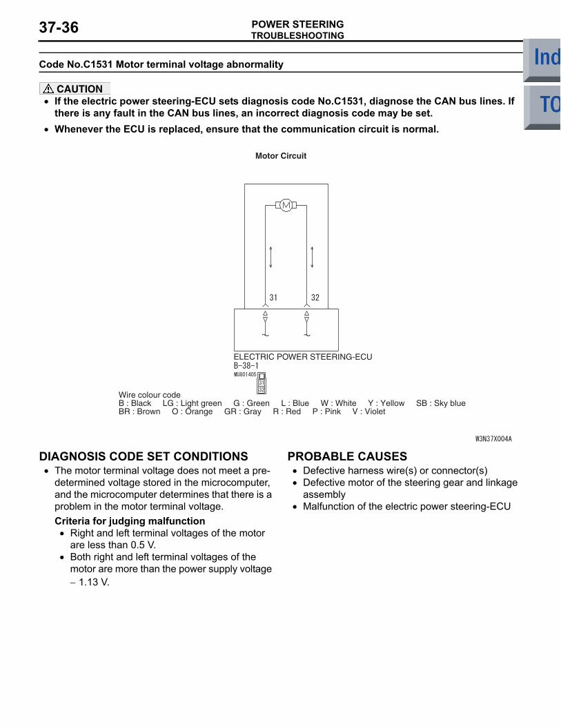
Code No.C1531 Motor terminal voltage abnormality
CAUTION• If the electric power steering-ECU sets diagnosis code No.C1531, diagnose the CAN bus lines. If
there is any fault in the CAN bus lines, an incorrect diagnosis code may be set.•
ELECTRIC POWER STEERING-ECU
Wire colour codeB : Black LG : Light green G : Green L : Blue W : White Y : Yellow SB : Sky blueBR : Brown O : Orange GR : Gray R : Red P : Pink V : Violet
Motor Circuit
Whenever the ECU is replaced, ensure that the communication circuit is normal.
DIAGNOSIS CODE SET CONDITIONS• The motor terminal voltage does not meet a pre-
determined voltage stored in the microcomputer, and the microcomputer determines that there is a problem in the motor terminal voltage.Criteria for judging malfunction
• Right and left terminal voltages of the motor are less than 0.5 V.
• Both right and left terminal voltages of the motor are more than the power supply voltage − 1.13 V.
PROBABLE CAUSES• Defective harness wire(s) or connector(s)• Defective motor of the steering gear and linkage
assembly• Malfunction of the electric power steering-ECU
TROUBLESHOOTINGPOWER STEERING 37-37
DIAGNOSTIC PROCEDURE
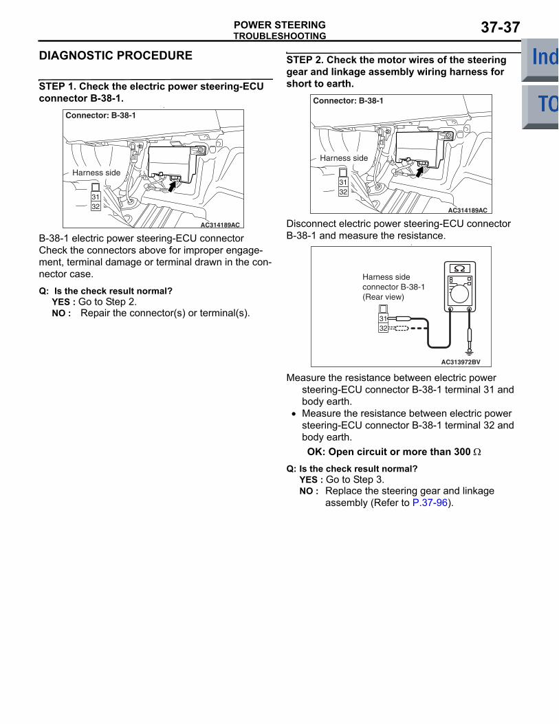
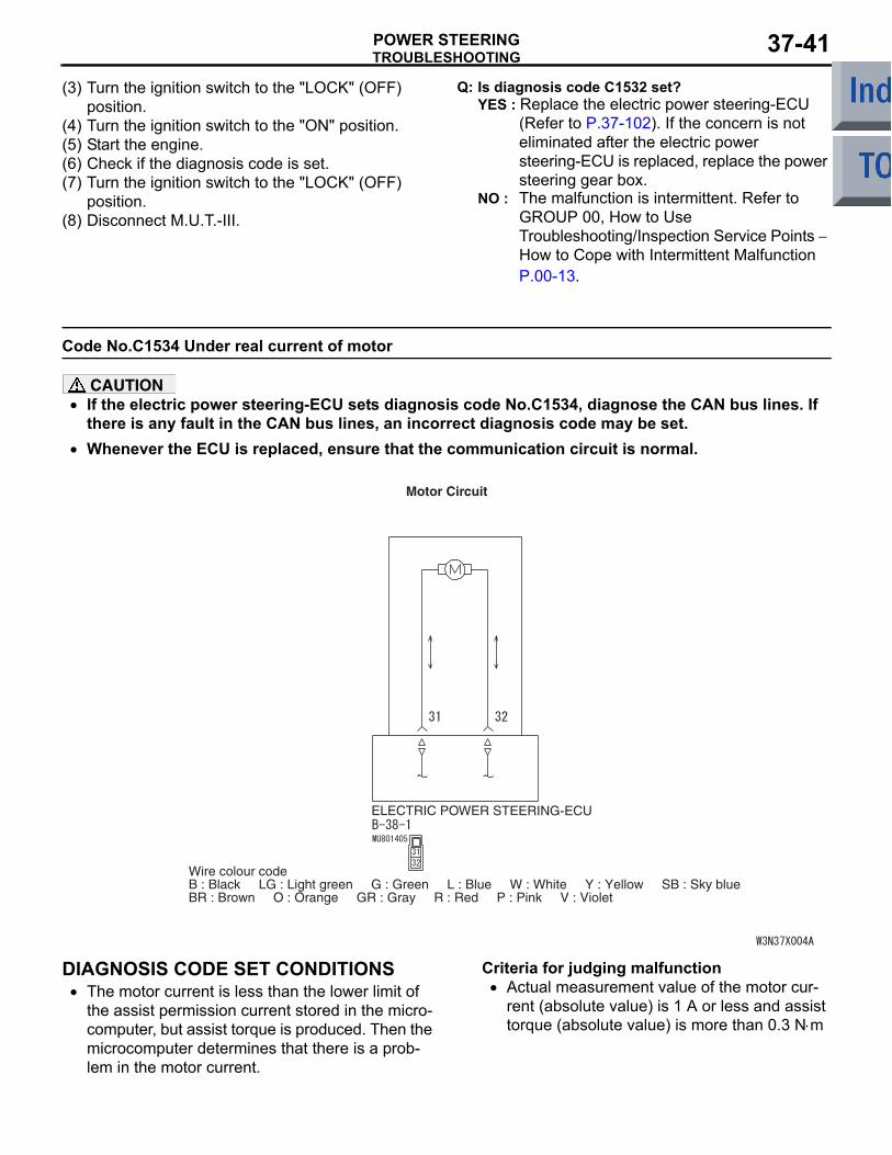
STEP 1. Check the electric power steering-ECU connector B-38-1.
•
AC314189AC
Connector: B-38-1
Harness side
B-38-1 electric power steering-ECU connectorCheck the connectors above for improper engage-ment, terminal damage or terminal drawn in the con-nector case.
Q: Is the check result normal?YES : Go to Step 2.NO : Repair the connector(s) or terminal(s).
STEP 2. Check the motor wires of the steering gear and linkage assembly wiring harness for short to earth.
AC314189AC
Connector: B-38-1
Harness side
Disconnect electric power steering-ECU connector B-38-1 and measure the resistance.
•
AC313972BV
Harness sideconnector B-38-1(Rear view)
Measure the resistance between electric power steering-ECU connector B-38-1 terminal 31 and body earth.
• Measure the resistance between electric power steering-ECU connector B-38-1 terminal 32 and body earth.OK: Open circuit or more than 300 Ω
Q: Is the check result normal?YES : Go to Step 3.NO : Replace the steering gear and linkage
assembly (Refer to P.37-96).
TROUBLESHOOTINGPOWER STEERING37-38
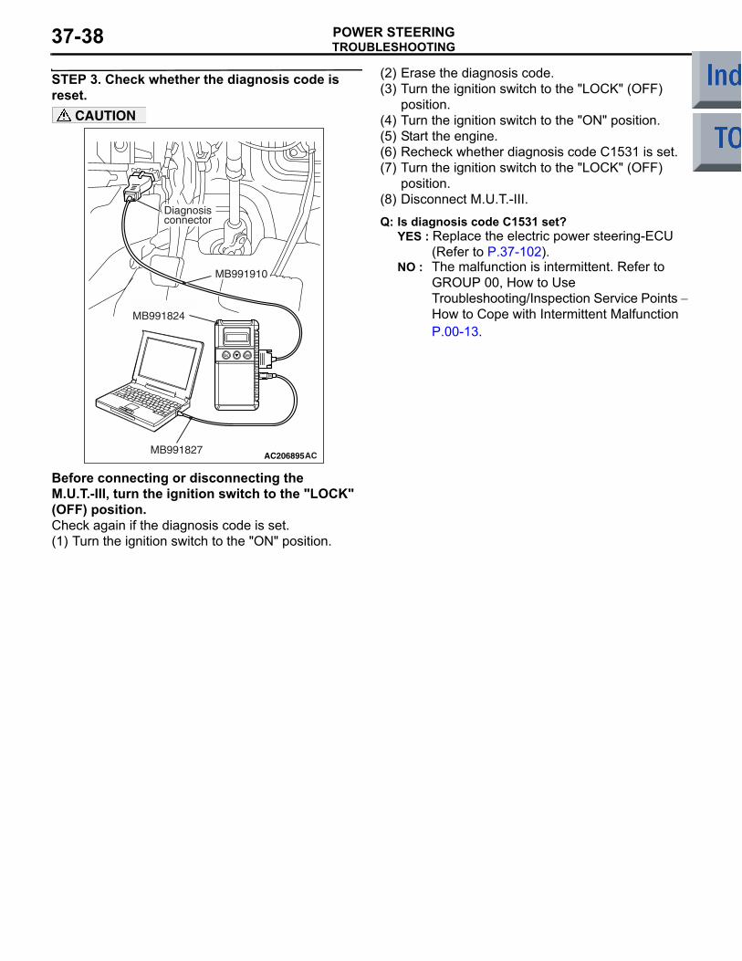
STEP 3. Check whether the diagnosis code is reset.
AC206895AC
Diagnosisconnector
MB991827
MB991824
MB991910
CAUTION
Before connecting or disconnecting the M.U.T.-III, turn the ignition switch to the "LOCK" (OFF) position.Check again if the diagnosis code is set.(1) Turn the ignition switch to the "ON" position.
(2) Erase the diagnosis code.(3) Turn the ignition switch to the "LOCK" (OFF)
position.(4) Turn the ignition switch to the "ON" position.(5) Start the engine.(6) Recheck whether diagnosis code C1531 is set.(7) Turn the ignition switch to the "LOCK" (OFF)
position.(8) Disconnect M.U.T.-III.
Q: Is diagnosis code C1531 set?YES : Replace the electric power steering-ECU
(Refer to P.37-102). NO : The malfunction is intermittent. Refer to
GROUP 00, How to Use Troubleshooting/Inspection Service Points − How to Cope with Intermittent Malfunction P.00-13.
TROUBLESHOOTINGPOWER STEERING 37-39
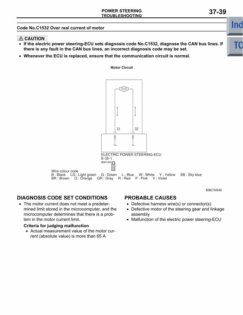
Code No.C1532 Over real current of motor
CAUTION• If the electric power steering-ECU sets diagnosis code No.C1532, diagnose the CAN bus lines. If
there is any fault in the CAN bus lines, an incorrect diagnosis code may be set.•
ELECTRIC POWER STEERING-ECU
Wire colour codeB : Black LG : Light green G : Green L : Blue W : White Y : Yellow SB : Sky blueBR : Brown O : Orange GR : Gray R : Red P : Pink V : Violet
Motor Circuit
Whenever the ECU is replaced, ensure that the communication circuit is normal.
DIAGNOSIS CODE SET CONDITIONS• The motor current does not meet a predeter-
mined limit stored in the microcomputer, and the microcomputer determines that there is a prob-lem in the motor current limit.Criteria for judging malfunction
• Actual measurement value of the motor cur-rent (absolute value) is more than 65 A
PROBABLE CAUSES• Defective harness wire(s) or connector(s)• Defective motor of the steering gear and linkage
assembly• Malfunction of the electric power steering-ECU
TROUBLESHOOTINGPOWER STEERING37-40
DIAGNOSTIC PROCEDURE
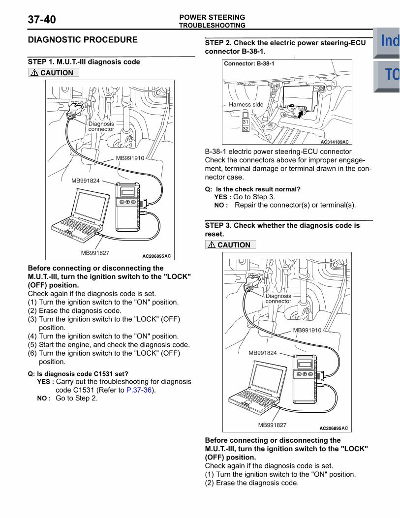
STEP 1. M.U.T.-III diagnosis code
AC206895AC
Diagnosisconnector
MB991827
MB991824
MB991910
CAUTION
Before connecting or disconnecting the M.U.T.-III, turn the ignition switch to the "LOCK" (OFF) position.Check again if the diagnosis code is set.(1) Turn the ignition switch to the "ON" position.(2) Erase the diagnosis code.(3) Turn the ignition switch to the "LOCK" (OFF)
position.(4) Turn the ignition switch to the "ON" position.(5) Start the engine, and check the diagnosis code.(6) Turn the ignition switch to the "LOCK" (OFF)
position.
Q: Is diagnosis code C1531 set?YES : Carry out the troubleshooting for diagnosis
code C1531 (Refer to P.37-36).NO : Go to Step 2.
STEP 2. Check the electric power steering-ECU connector B-38-1.
•
AC314189AC
Connector: B-38-1
Harness side
B-38-1 electric power steering-ECU connectorCheck the connectors above for improper engage-ment, terminal damage or terminal drawn in the con-nector case.
Q: Is the check result normal?YES : Go to Step 3.NO : Repair the connector(s) or terminal(s).
STEP 3. Check whether the diagnosis code is reset.
AC206895AC
Diagnosisconnector
MB991827
MB991824
MB991910
CAUTION
Before connecting or disconnecting the M.U.T.-III, turn the ignition switch to the "LOCK" (OFF) position.Check again if the diagnosis code is set.(1) Turn the ignition switch to the "ON" position.(2) Erase the diagnosis code.
TROUBLESHOOTINGPOWER STEERING 37-41
(3) Turn the ignition switch to the "LOCK" (OFF) position.
(4) Turn the ignition switch to the "ON" position.(5) Start the engine.(6) Check if the diagnosis code is set.(7) Turn the ignition switch to the "LOCK" (OFF)
position.(8) Disconnect M.U.T.-III.
Q: Is diagnosis code C1532 set?YES : Replace the electric power steering-ECU
(Refer to P.37-102). If the concern is not eliminated after the electric power steering-ECU is replaced, replace the power steering gear box.
NO : The malfunction is intermittent. Refer to GROUP 00, How to Use Troubleshooting/Inspection Service Points − How to Cope with Intermittent Malfunction P.00-13.
Code No.C1534 Under real current of motor
CAUTION• If the electric power steering-ECU sets diagnosis code No.C1534, diagnose the CAN bus lines. If
there is any fault in the CAN bus lines, an incorrect diagnosis code may be set.•
ELECTRIC POWER STEERING-ECU
Wire colour codeB : Black LG : Light green G : Green L : Blue W : White Y : Yellow SB : Sky blueBR : Brown O : Orange GR : Gray R : Red P : Pink V : Violet
Motor Circuit
Whenever the ECU is replaced, ensure that the communication circuit is normal.
DIAGNOSIS CODE SET CONDITIONS• The motor current is less than the lower limit of
the assist permission current stored in the micro-computer, but assist torque is produced. Then the microcomputer determines that there is a prob-lem in the motor current.
Criteria for judging malfunction• Actual measurement value of the motor cur-
rent (absolute value) is 1 A or less and assist torque (absolute value) is more than 0.3 N⋅m
TROUBLESHOOTINGPOWER STEERING37-42
PROBABLE CAUSES• Defective harness wire(s) or connector(s)• Malfunction of the electric power steering-ECU• Motor malfunction
DIAGNOSTIC PROCEDURE
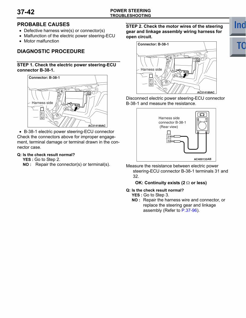
STEP 1. Check the electric power steering-ECU connector B-38-1.
AC314189AC
Connector: B-38-1
Harness side
• B-38-1 electric power steering-ECU connectorCheck the connectors above for improper engage-ment, terminal damage or terminal drawn in the con-nector case.
Q: Is the check result normal?YES : Go to Step 2.NO : Repair the connector(s) or terminal(s).
STEP 2. Check the motor wires of the steering gear and linkage assembly wiring harness for open circuit.
AC314189AC
Connector: B-38-1
Harness side
Disconnect electric power steering-ECU connector B-38-1 and measure the resistance.
•
AC400133AB
Harness sideconnector B-38-1 (Rear view)
Measure the resistance between electric power steering-ECU connector B-38-1 terminals 31 and 32.OK: Continuity exists (2 Ω or less)
Q: Is the check result normal?YES : Go to Step 3.NO : Repair the harness wire and connector, or
replace the steering gear and linkage assembly (Refer to P.37-96).
TROUBLESHOOTINGPOWER STEERING 37-43
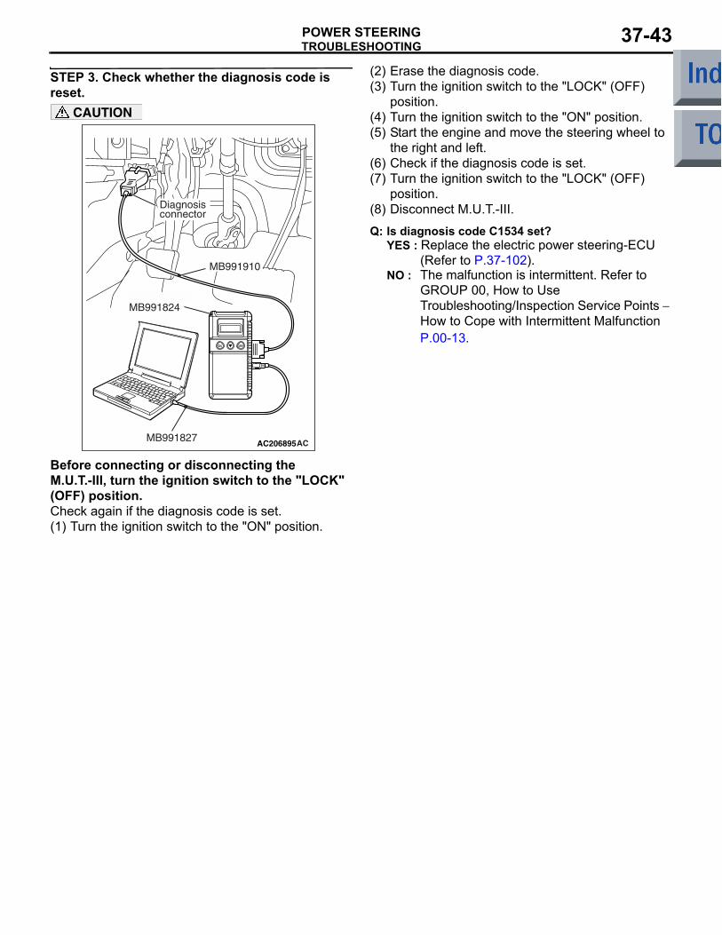
STEP 3. Check whether the diagnosis code is reset.
AC206895AC
Diagnosisconnector
MB991827
MB991824
MB991910
CAUTION
Before connecting or disconnecting the M.U.T.-III, turn the ignition switch to the "LOCK" (OFF) position.Check again if the diagnosis code is set.(1) Turn the ignition switch to the "ON" position.
(2) Erase the diagnosis code.(3) Turn the ignition switch to the "LOCK" (OFF)
position.(4) Turn the ignition switch to the "ON" position.(5) Start the engine and move the steering wheel to
the right and left.(6) Check if the diagnosis code is set.(7) Turn the ignition switch to the "LOCK" (OFF)
position.(8) Disconnect M.U.T.-III.
Q: Is diagnosis code C1534 set?YES : Replace the electric power steering-ECU
(Refer to P.37-102).NO : The malfunction is intermittent. Refer to
GROUP 00, How to Use Troubleshooting/Inspection Service Points − How to Cope with Intermittent Malfunction P.00-13.
TROUBLESHOOTINGPOWER STEERING37-44
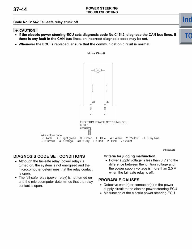
Code No.C1542 Fail-safe relay stuck off
CAUTION• If the electric power steering-ECU sets diagnosis code No.C1542, diagnose the CAN bus lines. If
there is any fault in the CAN bus lines, an incorrect diagnosis code may be set.•
ELECTRIC POWER STEERING-ECU
Wire colour codeB : Black LG : Light green G : Green L : Blue W : White Y : Yellow SB : Sky blueBR : Brown O : Orange GR : Gray R : Red P : Pink V : Violet
Motor Circuit
Whenever the ECU is replaced, ensure that the communication circuit is normal.
DIAGNOSIS CODE SET CONDITIONS• Although the fail-safe relay (power relay) is
turned on, the system is not energised and the microcomputer determines that the relay contact is open.
• The fail-safe relay (power relay) is not turned on and the microcomputer determines that the relay contact is open.
Criteria for judging malfunction• Power supply voltage is less than 8 V and the
difference between the ignition voltage and the power supply voltage is more than 2.5 V when the fail-safe relay is off.
PROBABLE CAUSES• Defective wire(s) or connector(s) in the power
supply circuit to the electric power steering-ECU• Malfunction of the electric power steering-ECU
TROUBLESHOOTINGPOWER STEERING 37-45
DIAGNOSTIC PROCEDURE
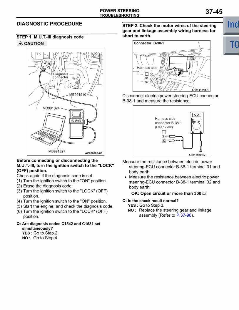
STEP 1. M.U.T.-III diagnosis code
AC206895AC
Diagnosisconnector
MB991827
MB991824
MB991910
CAUTION
Before connecting or disconnecting the M.U.T.-III, turn the ignition switch to the "LOCK" (OFF) position.Check again if the diagnosis code is set.(1) Turn the ignition switch to the "ON" position.(2) Erase the diagnosis code.(3) Turn the ignition switch to the "LOCK" (OFF)
position.(4) Turn the ignition switch to the "ON" position.(5) Start the engine, and check the diagnosis code.(6) Turn the ignition switch to the "LOCK" (OFF)
position.
Q: Are diagnosis codes C1542 and C1531 set simultaneously?YES : Go to Step 2.NO : Go to Step 4.
STEP 2. Check the motor wires of the steering gear and linkage assembly wiring harness for short to earth.
AC314189AC
Connector: B-38-1
Harness side
Disconnect electric power steering-ECU connector B-38-1 and measure the resistance.
•
AC313972BV
Harness sideconnector B-38-1(Rear view)
Measure the resistance between electric power steering-ECU connector B-38-1 terminal 31 and body earth.
• Measure the resistance between electric power steering-ECU connector B-38-1 terminal 32 and body earth.OK: Open circuit or more than 300 Ω
Q: Is the check result normal?YES : Go to Step 3.NO : Replace the steering gear and linkage
assembly (Refer to P.37-96).
TROUBLESHOOTINGPOWER STEERING37-46
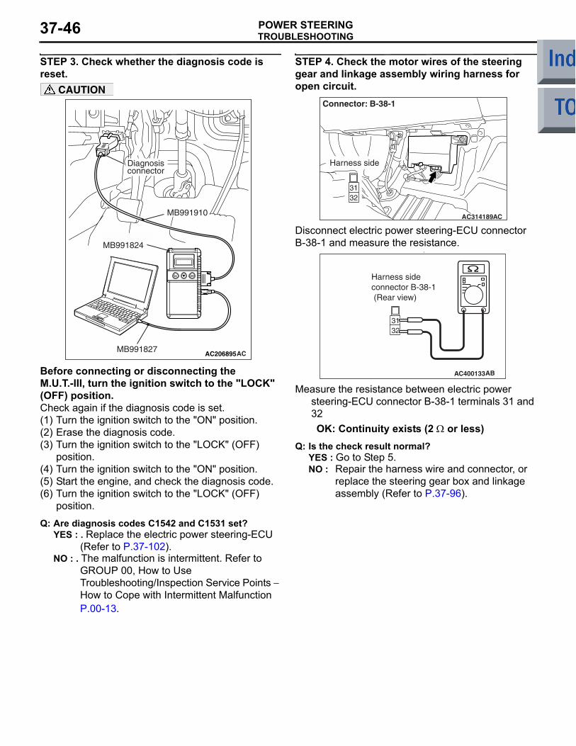
STEP 3. Check whether the diagnosis code is reset.
AC206895AC
Diagnosisconnector
MB991827
MB991824
MB991910
CAUTION
Before connecting or disconnecting the M.U.T.-III, turn the ignition switch to the "LOCK" (OFF) position.Check again if the diagnosis code is set.(1) Turn the ignition switch to the "ON" position.(2) Erase the diagnosis code.(3) Turn the ignition switch to the "LOCK" (OFF)
position.(4) Turn the ignition switch to the "ON" position.(5) Start the engine, and check the diagnosis code.(6) Turn the ignition switch to the "LOCK" (OFF)
position.
Q: Are diagnosis codes C1542 and C1531 set?YES : . Replace the electric power steering-ECU
(Refer to P.37-102). NO : . The malfunction is intermittent. Refer to
GROUP 00, How to Use Troubleshooting/Inspection Service Points − How to Cope with Intermittent Malfunction P.00-13.
STEP 4. Check the motor wires of the steering gear and linkage assembly wiring harness for open circuit.
AC314189AC
Connector: B-38-1
Harness side
Disconnect electric power steering-ECU connector B-38-1 and measure the resistance.
•
AC400133AB
Harness sideconnector B-38-1 (Rear view)
Measure the resistance between electric power steering-ECU connector B-38-1 terminals 31 and 32OK: Continuity exists (2 Ω or less)
Q: Is the check result normal?YES : Go to Step 5.NO : Repair the harness wire and connector, or
replace the steering gear box and linkage assembly (Refer to P.37-96).
TROUBLESHOOTINGPOWER STEERING 37-47
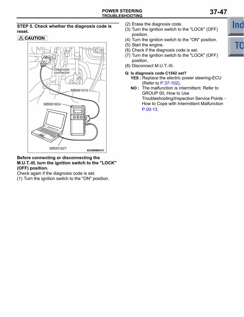
STEP 5. Check whether the diagnosis code is reset.
AC206895AC
Diagnosisconnector
MB991827
MB991824
MB991910
CAUTION
Before connecting or disconnecting the M.U.T.-III, turn the ignition switch to the "LOCK" (OFF) position.Check again if the diagnosis code is set.(1) Turn the ignition switch to the "ON" position.
(2) Erase the diagnosis code.(3) Turn the ignition switch to the "LOCK" (OFF)
position.(4) Turn the ignition switch to the "ON" position.(5) Start the engine.(6) Check if the diagnosis code is set.(7) Turn the ignition switch to the "LOCK" (OFF)
position.(8) Disconnect M.U.T.-III.
Q: Is diagnosis code C1542 set?YES : Replace the electric power steering-ECU
(Refer to P.37-102). NO : The malfunction is intermittent. Refer to
GROUP 00, How to Use Troubleshooting/Inspection Service Points − How to Cope with Intermittent Malfunction P.00-13.
TROUBLESHOOTINGPOWER STEERING37-48
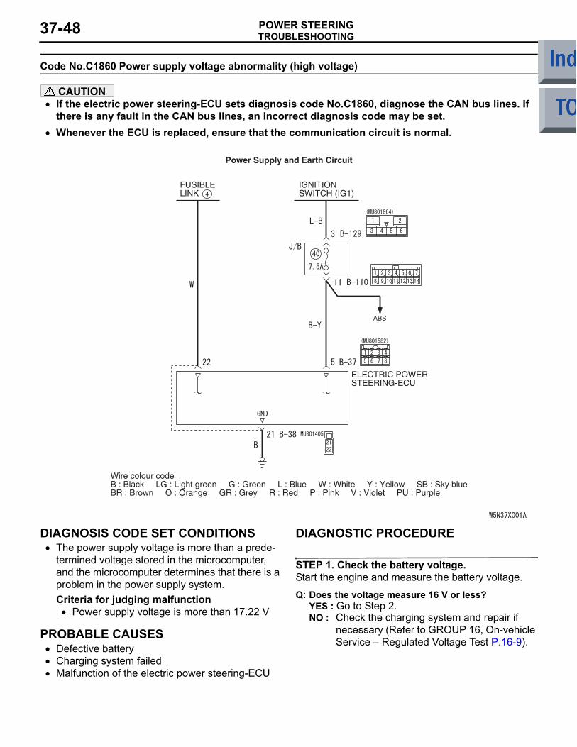
Code No.C1860 Power supply voltage abnormality (high voltage)
CAUTION• If the electric power steering-ECU sets diagnosis code No.C1860, diagnose the CAN bus lines. If
there is any fault in the CAN bus lines, an incorrect diagnosis code may be set.•
Power Supply and Earth Circuit
FUSIBLELINK
IGNITIONSWITCH (IG1)4
ABS
ELECTRIC POWERSTEERING-ECU
Wire colour codeB : Black LG : Light green G : Green L : Blue W : White Y : Yellow SB : Sky blueBR : Brown O : Orange GR : Grey R : Red P : Pink V : Violet PU : Purple
Whenever the ECU is replaced, ensure that the communication circuit is normal.
DIAGNOSIS CODE SET CONDITIONS• The power supply voltage is more than a prede-
termined voltage stored in the microcomputer, and the microcomputer determines that there is a problem in the power supply system.Criteria for judging malfunction
• Power supply voltage is more than 17.22 V
PROBABLE CAUSES• Defective battery• Charging system failed• Malfunction of the electric power steering-ECU
DIAGNOSTIC PROCEDURE
STEP 1. Check the battery voltage.Start the engine and measure the battery voltage.
Q: Does the voltage measure 16 V or less?YES : Go to Step 2.NO : Check the charging system and repair if
necessary (Refer to GROUP 16, On-vehicle Service − Regulated Voltage Test P.16-9).
TROUBLESHOOTINGPOWER STEERING 37-49
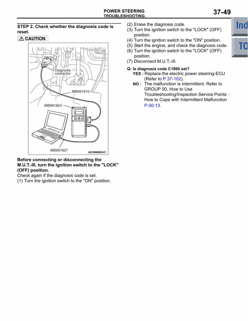
STEP 2. Check whether the diagnosis code is reset.
AC206895AC
Diagnosisconnector
MB991827
MB991824
MB991910
CAUTION
Before connecting or disconnecting the M.U.T.-III, turn the ignition switch to the "LOCK" (OFF) position.Check again if the diagnosis code is set.(1) Turn the ignition switch to the "ON" position.
(2) Erase the diagnosis code.(3) Turn the ignition switch to the "LOCK" (OFF)
position.(4) Turn the ignition switch to the "ON" position.(5) Start the engine, and check the diagnosis code.(6) Turn the ignition switch to the "LOCK" (OFF)
position.(7) Disconnect M.U.T.-III.
Q: Is diagnosis code C1860 set?YES : Replace the electric power steering-ECU
(Refer to P.37-102). NO : The malfunction is intermittent. Refer to
GROUP 00, How to Use Troubleshooting/Inspection Service Points − How to Cope with Intermittent Malfunction P.00-13.
TROUBLESHOOTINGPOWER STEERING37-50
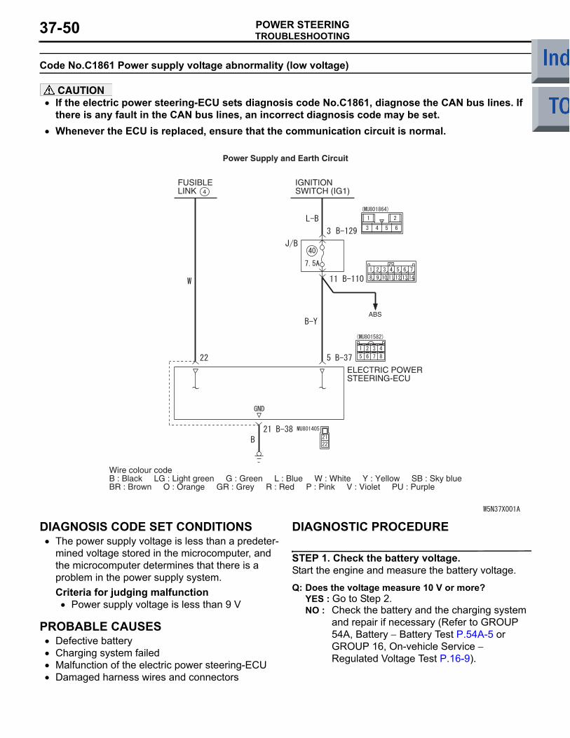
Code No.C1861 Power supply voltage abnormality (low voltage)
CAUTION• If the electric power steering-ECU sets diagnosis code No.C1861, diagnose the CAN bus lines. If
there is any fault in the CAN bus lines, an incorrect diagnosis code may be set.•
Power Supply and Earth Circuit
FUSIBLELINK
IGNITIONSWITCH (IG1)4
ABS
ELECTRIC POWERSTEERING-ECU
Wire colour codeB : Black LG : Light green G : Green L : Blue W : White Y : Yellow SB : Sky blueBR : Brown O : Orange GR : Grey R : Red P : Pink V : Violet PU : Purple
Whenever the ECU is replaced, ensure that the communication circuit is normal.
DIAGNOSIS CODE SET CONDITIONS• The power supply voltage is less than a predeter-
mined voltage stored in the microcomputer, and the microcomputer determines that there is a problem in the power supply system.Criteria for judging malfunction
• Power supply voltage is less than 9 V
PROBABLE CAUSES• Defective battery• Charging system failed• Malfunction of the electric power steering-ECU• Damaged harness wires and connectors
DIAGNOSTIC PROCEDURE
STEP 1. Check the battery voltage.Start the engine and measure the battery voltage.
Q: Does the voltage measure 10 V or more?YES : Go to Step 2.NO : Check the battery and the charging system
and repair if necessary (Refer to GROUP 54A, Battery − Battery Test P.54A-5 or GROUP 16, On-vehicle Service − Regulated Voltage Test P.16-9).
TROUBLESHOOTINGPOWER STEERING 37-51
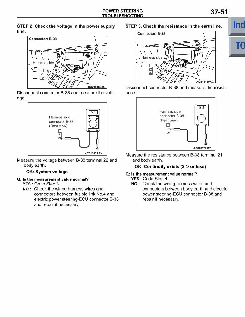
STEP 2. Check the voltage in the power supply line.
AC314189AC314189AC314189AG
Connector: B-38
Harness side
Disconnect connector B-38 and measure the volt-age.
•
AC313972BX
Harness sideconnector B-38(Rear view)
Measure the voltage between B-38 terminal 22 and body earth.OK: System voltage
Q: Is the measurement value normal?YES : Go to Step 3.NO : Check the wiring harness wires and
connectors between fusible link No.4 and electric power steering-ECU connector B-38 and repair if necessary.
STEP 3. Check the resistance in the earth line.
AC314189AC314189AC314189AG
Connector: B-38
Harness side
Disconnect connector B-38 and measure the resist-ance.
•
AC313972BY
Harness sideconnector B-38(Rear view)
Measure the resistance between B-38 terminal 21 and body earth.OK: Continuity exists (2 Ω or less)
Q: Is the measurement value normal?YES : Go to Step 4.NO : Check the wiring harness wires and
connectors between body earth and electric power steering-ECU connector B-38 and repair if necessary.

TROUBLESHOOTINGPOWER STEERING37-52
STEP 4. Check whether the diagnosis code is reset.
AC206895AC
Diagnosisconnector
MB991827
MB991824
MB991910
CAUTION
Before connecting or disconnecting the M.U.T.-III, turn the ignition switch to the "LOCK" (OFF) position.Check again if the diagnosis code is set.(1) Turn the ignition switch to the "ON" position.
(2) Erase the diagnosis code.(3) Turn the ignition switch to the "LOCK" (OFF)
position.(4) Turn the ignition switch to the "ON" position.(5) Start the engine, and check the diagnosis code.(6) Turn the ignition switch to the "LOCK" (OFF)
position.(7) Disconnect M.U.T.-III.
Q: Is diagnosis code C1861 set?YES : Replace the electric power steering-ECU
(Refer to P.37-102). NO : The malfunction is intermittent. Refer to
GROUP 00, How to Use Troubleshooting/Inspection Service Points − How to Cope with Intermittent Malfunction P.00-13.
TROUBLESHOOTINGPOWER STEERING 37-53
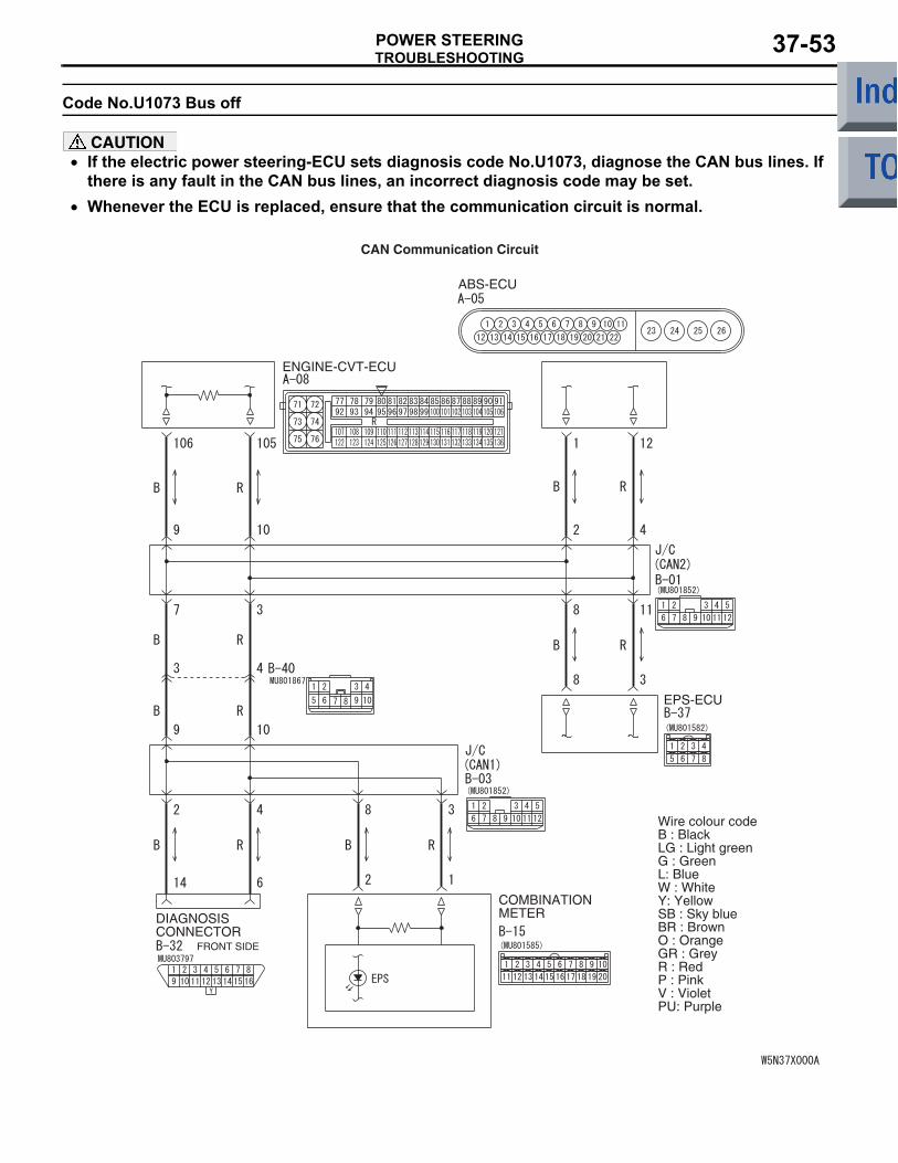
Code No.U1073 Bus off
CAUTION• If the electric power steering-ECU sets diagnosis code No.U1073, diagnose the CAN bus lines. If
there is any fault in the CAN bus lines, an incorrect diagnosis code may be set.•
ENGINE-CVT-ECU
DIAGNOSISCONNECTOR
FRONT SIDE
COMBINATIONMETER
ABS-ECU
EPS-ECU
Wire colour codeB : BlackLG : Light greenG : GreenL: BlueW : WhiteY: YellowSB : Sky blueBR : BrownO : OrangeGR : GreyR : RedP : PinkV : VioletPU: Purple
CAN Communication Circuit
Whenever the ECU is replaced, ensure that the communication circuit is normal.
TROUBLESHOOTINGPOWER STEERING37-54
TROUBLE JUDGMENTWhen the electric power steering-ECU is bus off, it is memorised.
COMMENTS ON TROUBLE SYMPTOMHarness wire(s), connector(s) or the electric power steering-ECU may be defective.
PROBABLE CAUSES• Defective wire(s) or connector(s) in the CAN bus
lines• Malfunction of the electric power steering-ECU
DIAGNOSIS PROCEDURE
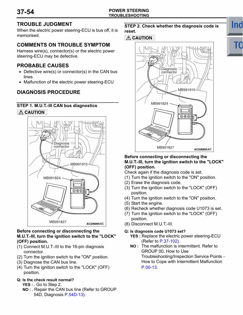
STEP 1. M.U.T.-III CAN bus diagnostics
AC206895AC
Diagnosisconnector
MB991827
MB991824
MB991910
CAUTION
Before connecting or disconnecting the M.U.T.-III, turn the ignition switch to the "LOCK" (OFF) position.(1) Connect M.U.T.-III to the 16-pin diagnosis
connector.(2) Turn the ignition switch to the "ON" position.(3) Diagnose the CAN bus line.(4) Turn the ignition switch to the "LOCK" (OFF)
position.
Q: Is the check result normal?YES : . Go to Step 2.NO : . Repair the CAN bus line (Refer to GROUP
54D, Diagnosis P.54D-13).
STEP 2. Check whether the diagnosis code is reset.
AC206895AC
Diagnosisconnector
MB991827
MB991824
MB991910
CAUTION
Before connecting or disconnecting the M.U.T.-III, turn the ignition switch to the "LOCK" (OFF) position.Check again if the diagnosis code is set.(1) Turn the ignition switch to the "ON" position.(2) Erase the diagnosis code.(3) Turn the ignition switch to the "LOCK" (OFF)
position.(4) Turn the ignition switch to the "ON" position.(5) Start the engine.(6) Recheck whether diagnosis code U1073 is set.(7) Turn the ignition switch to the "LOCK" (OFF)
position.(8) Disconnect M.U.T.-III.
Q: Is diagnosis code U1073 set?YES : Replace the electric power steering-ECU
(Refer to P.37-102).NO : The malfunction is intermittent. Refer to
GROUP 00, How to Use Troubleshooting/Inspection Service Points − How to Cope with Intermittent Malfunction P.00-13.
TROUBLESHOOTINGPOWER STEERING 37-55
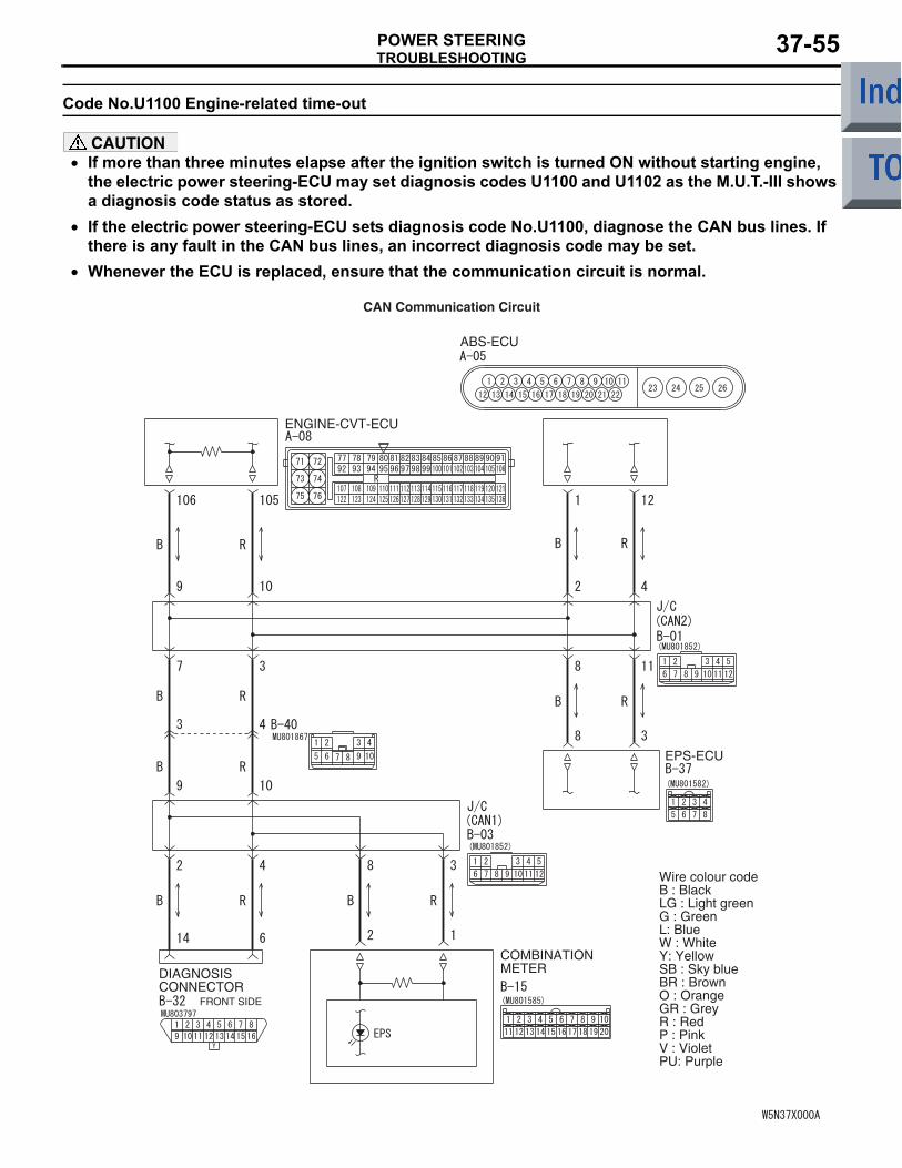
Code No.U1100 Engine-related time-out
CAUTION• If more than three minutes elapse after the ignition switch is turned ON without starting engine,
the electric power steering-ECU may set diagnosis codes U1100 and U1102 as the M.U.T.-III shows a diagnosis code status as stored.
• If the electric power steering-ECU sets diagnosis code No.U1100, diagnose the CAN bus lines. If there is any fault in the CAN bus lines, an incorrect diagnosis code may be set.
•
ENGINE-CVT-ECU
DIAGNOSISCONNECTOR
FRONT SIDE
COMBINATIONMETER
ABS-ECU
EPS-ECU
Wire colour codeB : BlackLG : Light greenG : GreenL: BlueW : WhiteY: YellowSB : Sky blueBR : BrownO : OrangeGR : GreyR : RedP : PinkV : VioletPU: Purple
CAN Communication Circuit
Whenever the ECU is replaced, ensure that the communication circuit is normal.
TROUBLESHOOTINGPOWER STEERING37-56
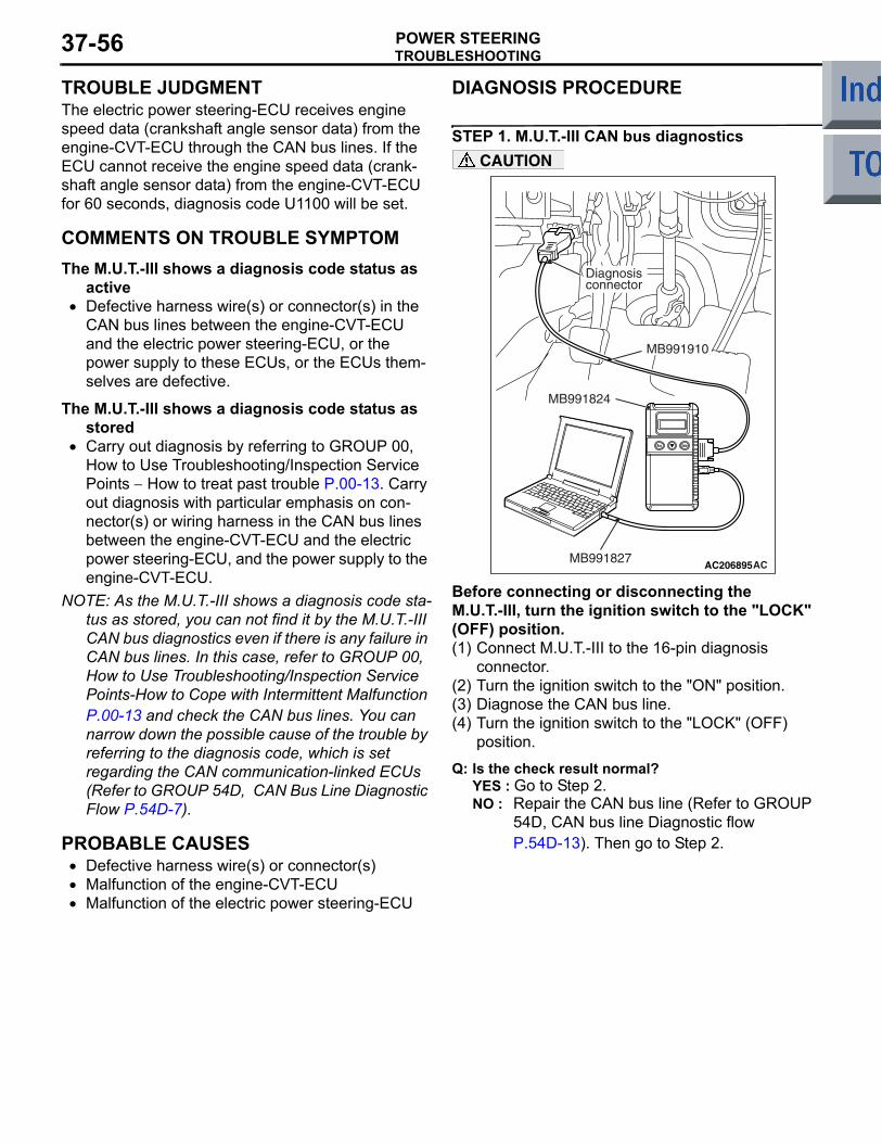
TROUBLE JUDGMENTThe electric power steering-ECU receives engine speed data (crankshaft angle sensor data) from the engine-CVT-ECU through the CAN bus lines. If the ECU cannot receive the engine speed data (crank-shaft angle sensor data) from the engine-CVT-ECU for 60 seconds, diagnosis code U1100 will be set.
COMMENTS ON TROUBLE SYMPTOMThe M.U.T.-III shows a diagnosis code status as
active• Defective harness wire(s) or connector(s) in the
CAN bus lines between the engine-CVT-ECU and the electric power steering-ECU, or the power supply to these ECUs, or the ECUs them-selves are defective.
The M.U.T.-III shows a diagnosis code status as stored
• Carry out diagnosis by referring to GROUP 00, How to Use Troubleshooting/Inspection Service Points − How to treat past trouble P.00-13. Carry out diagnosis with particular emphasis on con-nector(s) or wiring harness in the CAN bus lines between the engine-CVT-ECU and the electric power steering-ECU, and the power supply to the engine-CVT-ECU.
NOTE: As the M.U.T.-III shows a diagnosis code sta-tus as stored, you can not find it by the M.U.T.-III CAN bus diagnostics even if there is any failure in CAN bus lines. In this case, refer to GROUP 00, How to Use Troubleshooting/Inspection Service Points-How to Cope with Intermittent Malfunction P.00-13 and check the CAN bus lines. You can narrow down the possible cause of the trouble by referring to the diagnosis code, which is set regarding the CAN communication-linked ECUs (Refer to GROUP 54D, CAN Bus Line Diagnostic Flow P.54D-7).
PROBABLE CAUSES• Defective harness wire(s) or connector(s)• Malfunction of the engine-CVT-ECU• Malfunction of the electric power steering-ECU
DIAGNOSIS PROCEDURE
STEP 1. M.U.T.-III CAN bus diagnostics
AC206895AC
Diagnosisconnector
MB991827
MB991824
MB991910
CAUTION
Before connecting or disconnecting the M.U.T.-III, turn the ignition switch to the "LOCK" (OFF) position.(1) Connect M.U.T.-III to the 16-pin diagnosis
connector.(2) Turn the ignition switch to the "ON" position.(3) Diagnose the CAN bus line.(4) Turn the ignition switch to the "LOCK" (OFF)
position.
Q: Is the check result normal?YES : Go to Step 2.NO : Repair the CAN bus line (Refer to GROUP
54D, CAN bus line Diagnostic flow P.54D-13). Then go to Step 2.
TROUBLESHOOTINGPOWER STEERING 37-57
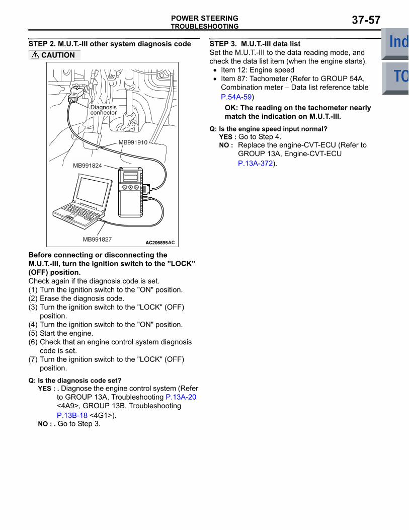
STEP 2. M.U.T.-III other system diagnosis code
AC206895AC
Diagnosisconnector
MB991827
MB991824
MB991910
CAUTION
Before connecting or disconnecting the M.U.T.-III, turn the ignition switch to the "LOCK" (OFF) position.Check again if the diagnosis code is set.(1) Turn the ignition switch to the "ON" position.(2) Erase the diagnosis code.(3) Turn the ignition switch to the "LOCK" (OFF)
position.(4) Turn the ignition switch to the "ON" position.(5) Start the engine.(6) Check that an engine control system diagnosis
code is set.(7) Turn the ignition switch to the "LOCK" (OFF)
position.
Q: Is the diagnosis code set?YES : . Diagnose the engine control system (Refer
to GROUP 13A, Troubleshooting P.13A-20 <4A9>, GROUP 13B, Troubleshooting P.13B-18 <4G1>).
NO : . Go to Step 3.
STEP 3. M.U.T.-III data listSet the M.U.T.-III to the data reading mode, and check the data list item (when the engine starts).
• Item 12: Engine speed• Item 87: Tachometer (Refer to GROUP 54A,
Combination meter − Data list reference table P.54A-59)OK: The reading on the tachometer nearly match the indication on M.U.T.-III.
Q: Is the engine speed input normal?YES : Go to Step 4.NO : Replace the engine-CVT-ECU (Refer to
GROUP 13A, Engine-CVT-ECU P.13A-372).
TROUBLESHOOTINGPOWER STEERING37-58
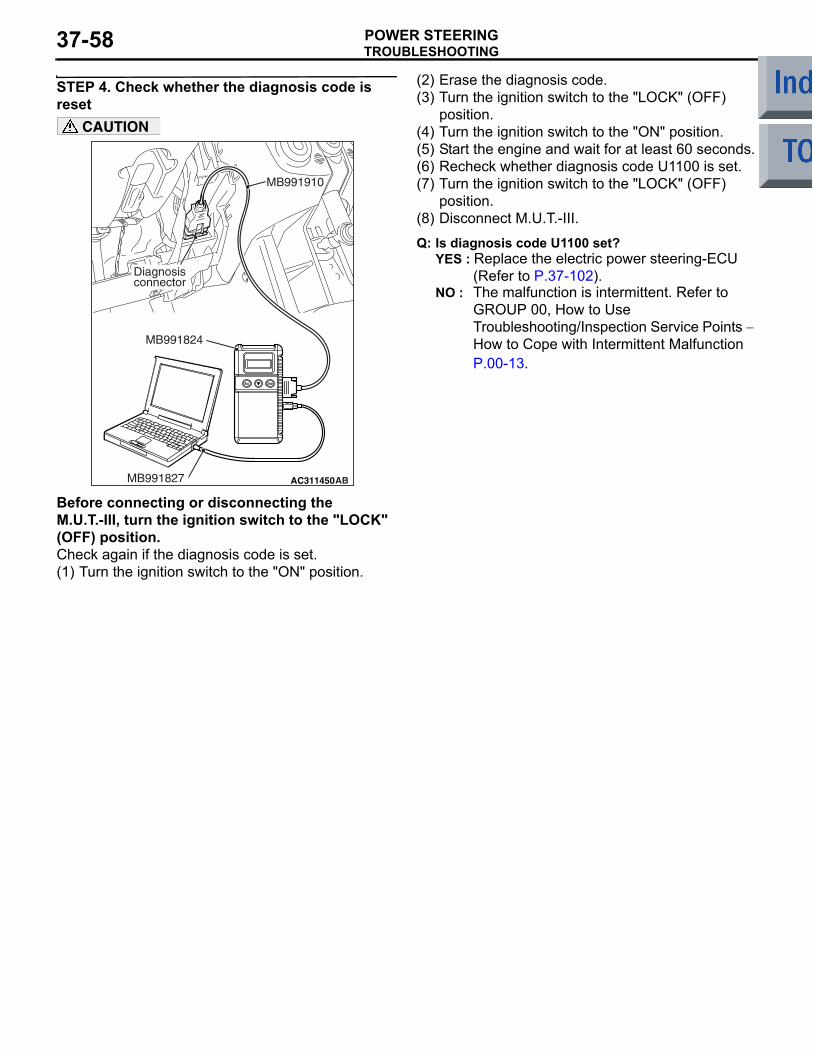
STEP 4. Check whether the diagnosis code is reset
AC206895
AC311450AB
Diagnosisconnector
MB991827
MB991824
MB991910
CAUTION
Before connecting or disconnecting the M.U.T.-III, turn the ignition switch to the "LOCK" (OFF) position.Check again if the diagnosis code is set.(1) Turn the ignition switch to the "ON" position.
(2) Erase the diagnosis code.(3) Turn the ignition switch to the "LOCK" (OFF)
position.(4) Turn the ignition switch to the "ON" position.(5) Start the engine and wait for at least 60 seconds.(6) Recheck whether diagnosis code U1100 is set.(7) Turn the ignition switch to the "LOCK" (OFF)
position.(8) Disconnect M.U.T.-III.
Q: Is diagnosis code U1100 set?YES : Replace the electric power steering-ECU
(Refer to P.37-102).NO : The malfunction is intermittent. Refer to
GROUP 00, How to Use Troubleshooting/Inspection Service Points − How to Cope with Intermittent Malfunction P.00-13.
TROUBLESHOOTINGPOWER STEERING 37-59
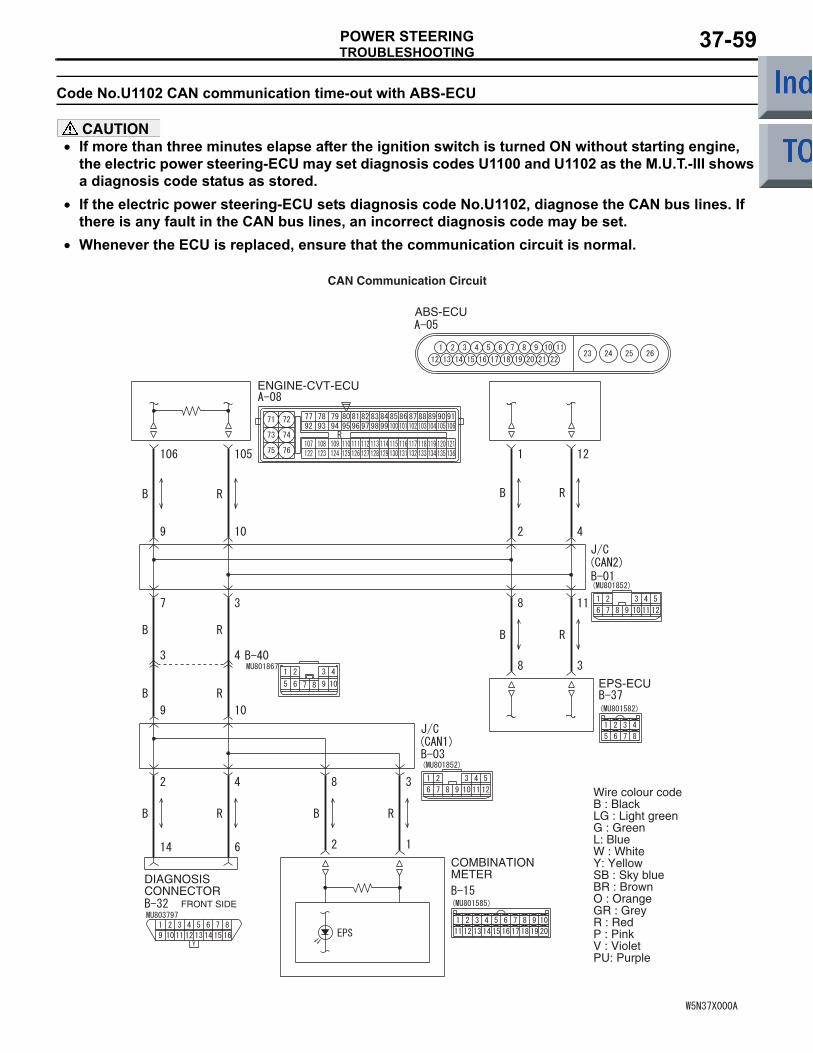
Code No.U1102 CAN communication time-out with ABS-ECU
CAUTION• If more than three minutes elapse after the ignition switch is turned ON without starting engine,
the electric power steering-ECU may set diagnosis codes U1100 and U1102 as the M.U.T.-III shows a diagnosis code status as stored.
• If the electric power steering-ECU sets diagnosis code No.U1102, diagnose the CAN bus lines. If there is any fault in the CAN bus lines, an incorrect diagnosis code may be set.
•
ENGINE-CVT-ECU
DIAGNOSISCONNECTOR
FRONT SIDE
COMBINATIONMETER
ABS-ECU
EPS-ECU
Wire colour codeB : BlackLG : Light greenG : GreenL: BlueW : WhiteY: YellowSB : Sky blueBR : BrownO : OrangeGR : GreyR : RedP : PinkV : VioletPU: Purple
CAN Communication Circuit
Whenever the ECU is replaced, ensure that the communication circuit is normal.
TROUBLESHOOTINGPOWER STEERING37-60
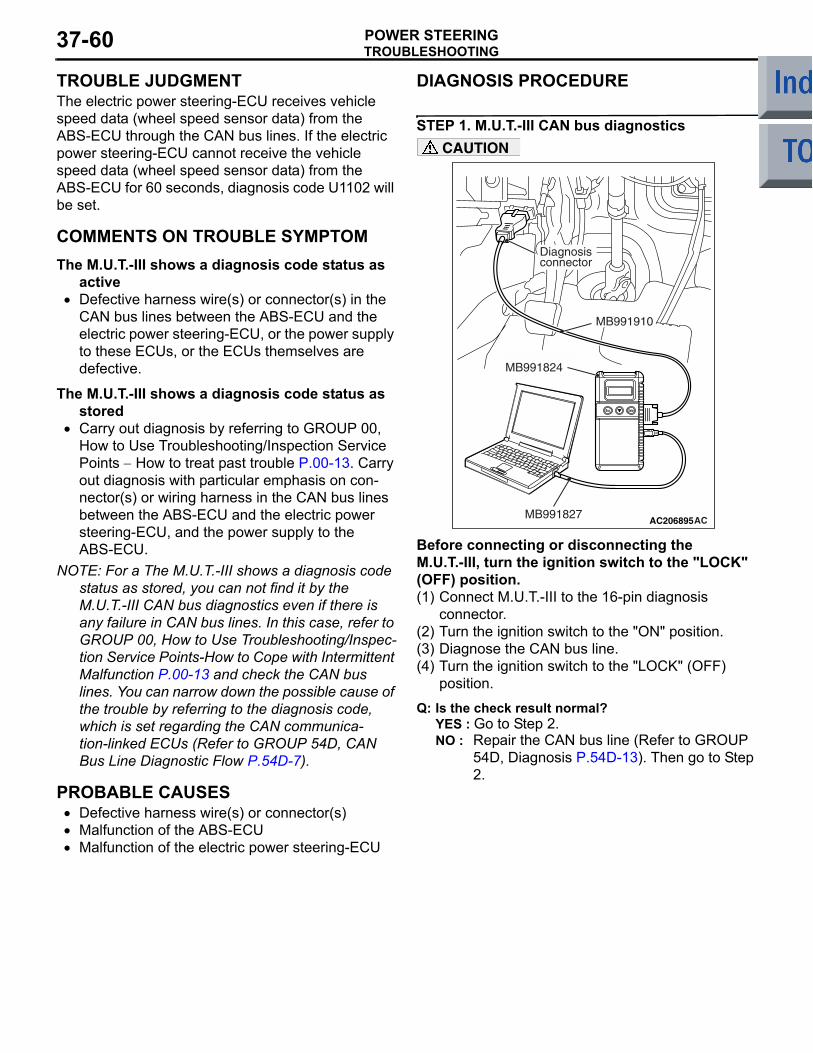
TROUBLE JUDGMENTThe electric power steering-ECU receives vehicle speed data (wheel speed sensor data) from the ABS-ECU through the CAN bus lines. If the electric power steering-ECU cannot receive the vehicle speed data (wheel speed sensor data) from the ABS-ECU for 60 seconds, diagnosis code U1102 will be set.
COMMENTS ON TROUBLE SYMPTOMThe M.U.T.-III shows a diagnosis code status as
active• Defective harness wire(s) or connector(s) in the
CAN bus lines between the ABS-ECU and the electric power steering-ECU, or the power supply to these ECUs, or the ECUs themselves are defective.
The M.U.T.-III shows a diagnosis code status as stored
• Carry out diagnosis by referring to GROUP 00, How to Use Troubleshooting/Inspection Service Points − How to treat past trouble P.00-13. Carry out diagnosis with particular emphasis on con-nector(s) or wiring harness in the CAN bus lines between the ABS-ECU and the electric power steering-ECU, and the power supply to the ABS-ECU.
NOTE: For a The M.U.T.-III shows a diagnosis code status as stored, you can not find it by the M.U.T.-III CAN bus diagnostics even if there is any failure in CAN bus lines. In this case, refer to GROUP 00, How to Use Troubleshooting/Inspec-tion Service Points-How to Cope with Intermittent Malfunction P.00-13 and check the CAN bus lines. You can narrow down the possible cause of the trouble by referring to the diagnosis code, which is set regarding the CAN communica-tion-linked ECUs (Refer to GROUP 54D, CAN Bus Line Diagnostic Flow P.54D-7).
PROBABLE CAUSES• Defective harness wire(s) or connector(s)• Malfunction of the ABS-ECU• Malfunction of the electric power steering-ECU
DIAGNOSIS PROCEDURE
STEP 1. M.U.T.-III CAN bus diagnostics
AC206895AC
Diagnosisconnector
MB991827
MB991824
MB991910
CAUTION
Before connecting or disconnecting the M.U.T.-III, turn the ignition switch to the "LOCK" (OFF) position.(1) Connect M.U.T.-III to the 16-pin diagnosis
connector.(2) Turn the ignition switch to the "ON" position.(3) Diagnose the CAN bus line.(4) Turn the ignition switch to the "LOCK" (OFF)
position.
Q: Is the check result normal?YES : Go to Step 2.NO : Repair the CAN bus line (Refer to GROUP
54D, Diagnosis P.54D-13). Then go to Step 2.
TROUBLESHOOTINGPOWER STEERING 37-61
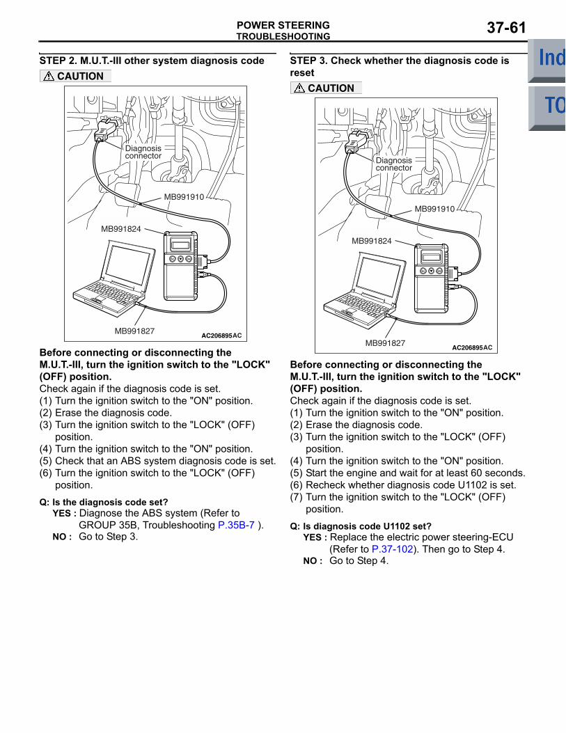
STEP 2. M.U.T.-III other system diagnosis code
AC206895AC
Diagnosisconnector
MB991827
MB991824
MB991910
CAUTION
Before connecting or disconnecting the M.U.T.-III, turn the ignition switch to the "LOCK" (OFF) position.Check again if the diagnosis code is set.(1) Turn the ignition switch to the "ON" position.(2) Erase the diagnosis code.(3) Turn the ignition switch to the "LOCK" (OFF)
position.(4) Turn the ignition switch to the "ON" position.(5) Check that an ABS system diagnosis code is set.(6) Turn the ignition switch to the "LOCK" (OFF)
position.
Q: Is the diagnosis code set?YES : Diagnose the ABS system (Refer to
GROUP 35B, Troubleshooting P.35B-7 ).NO : Go to Step 3.
STEP 3. Check whether the diagnosis code is reset
AC206895AC
Diagnosisconnector
MB991827
MB991824
MB991910
CAUTION
Before connecting or disconnecting the M.U.T.-III, turn the ignition switch to the "LOCK" (OFF) position.Check again if the diagnosis code is set.(1) Turn the ignition switch to the "ON" position.(2) Erase the diagnosis code.(3) Turn the ignition switch to the "LOCK" (OFF)
position.(4) Turn the ignition switch to the "ON" position.(5) Start the engine and wait for at least 60 seconds.(6) Recheck whether diagnosis code U1102 is set.(7) Turn the ignition switch to the "LOCK" (OFF)
position.
Q: Is diagnosis code U1102 set?YES : Replace the electric power steering-ECU
(Refer to P.37-102). Then go to Step 4.NO : Go to Step 4.
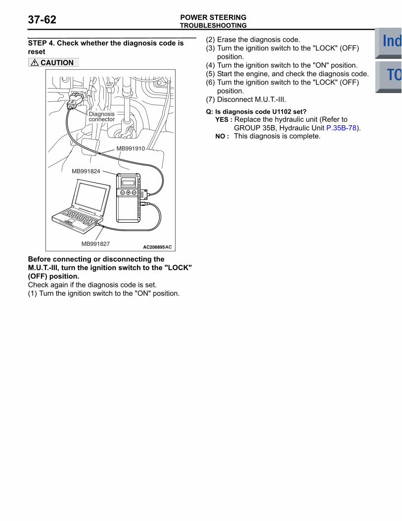
TROUBLESHOOTINGPOWER STEERING37-62
STEP 4. Check whether the diagnosis code is reset
AC206895AC
Diagnosisconnector
MB991827
MB991824
MB991910
CAUTION
Before connecting or disconnecting the M.U.T.-III, turn the ignition switch to the "LOCK" (OFF) position.Check again if the diagnosis code is set.(1) Turn the ignition switch to the "ON" position.
(2) Erase the diagnosis code.(3) Turn the ignition switch to the "LOCK" (OFF)
position.(4) Turn the ignition switch to the "ON" position.(5) Start the engine, and check the diagnosis code.(6) Turn the ignition switch to the "LOCK" (OFF)
position.(7) Disconnect M.U.T.-III.
Q: Is diagnosis code U1102 set?YES : Replace the hydraulic unit (Refer to
GROUP 35B, Hydraulic Unit P.35B-78).NO : This diagnosis is complete.
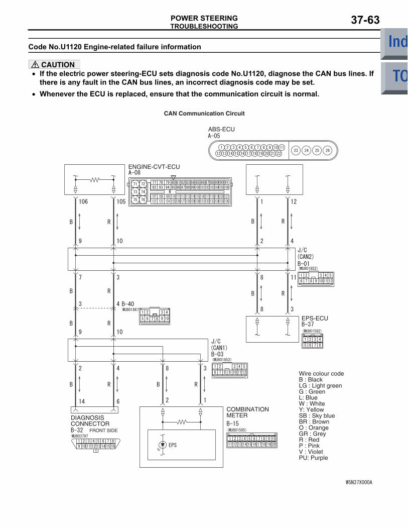
TROUBLESHOOTINGPOWER STEERING 37-63
Code No.U1120 Engine-related failure information
CAUTION• If the electric power steering-ECU sets diagnosis code No.U1120, diagnose the CAN bus lines. If
there is any fault in the CAN bus lines, an incorrect diagnosis code may be set.•
ENGINE-CVT-ECU
DIAGNOSISCONNECTOR
FRONT SIDE
COMBINATIONMETER
ABS-ECU
EPS-ECU
Wire colour codeB : BlackLG : Light greenG : GreenL: BlueW : WhiteY: YellowSB : Sky blueBR : BrownO : OrangeGR : GreyR : RedP : PinkV : VioletPU: Purple
CAN Communication Circuit
Whenever the ECU is replaced, ensure that the communication circuit is normal.
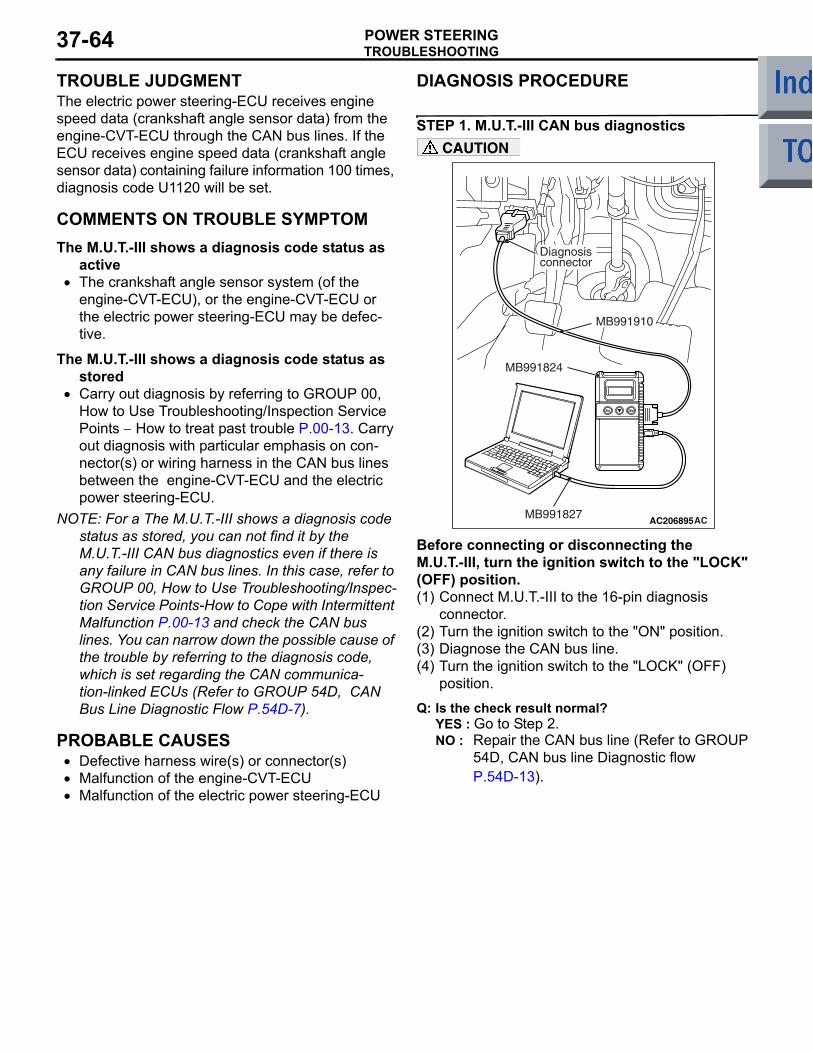
TROUBLESHOOTINGPOWER STEERING37-64
TROUBLE JUDGMENTThe electric power steering-ECU receives engine speed data (crankshaft angle sensor data) from the engine-CVT-ECU through the CAN bus lines. If the ECU receives engine speed data (crankshaft angle sensor data) containing failure information 100 times, diagnosis code U1120 will be set.
COMMENTS ON TROUBLE SYMPTOMThe M.U.T.-III shows a diagnosis code status as
active• The crankshaft angle sensor system (of the
engine-CVT-ECU), or the engine-CVT-ECU or the electric power steering-ECU may be defec-tive.
The M.U.T.-III shows a diagnosis code status as stored
• Carry out diagnosis by referring to GROUP 00, How to Use Troubleshooting/Inspection Service Points − How to treat past trouble P.00-13. Carry out diagnosis with particular emphasis on con-nector(s) or wiring harness in the CAN bus lines between the engine-CVT-ECU and the electric power steering-ECU.
NOTE: For a The M.U.T.-III shows a diagnosis code status as stored, you can not find it by the M.U.T.-III CAN bus diagnostics even if there is any failure in CAN bus lines. In this case, refer to GROUP 00, How to Use Troubleshooting/Inspec-tion Service Points-How to Cope with Intermittent Malfunction P.00-13 and check the CAN bus lines. You can narrow down the possible cause of the trouble by referring to the diagnosis code, which is set regarding the CAN communica-tion-linked ECUs (Refer to GROUP 54D, CAN Bus Line Diagnostic Flow P.54D-7).
PROBABLE CAUSES• Defective harness wire(s) or connector(s)• Malfunction of the engine-CVT-ECU• Malfunction of the electric power steering-ECU
DIAGNOSIS PROCEDURE
STEP 1. M.U.T.-III CAN bus diagnostics
AC206895AC
Diagnosisconnector
MB991827
MB991824
MB991910
CAUTION
Before connecting or disconnecting the M.U.T.-III, turn the ignition switch to the "LOCK" (OFF) position.(1) Connect M.U.T.-III to the 16-pin diagnosis
connector.(2) Turn the ignition switch to the "ON" position.(3) Diagnose the CAN bus line.(4) Turn the ignition switch to the "LOCK" (OFF)
position.
Q: Is the check result normal?YES : Go to Step 2.NO : Repair the CAN bus line (Refer to GROUP
54D, CAN bus line Diagnostic flow P.54D-13).
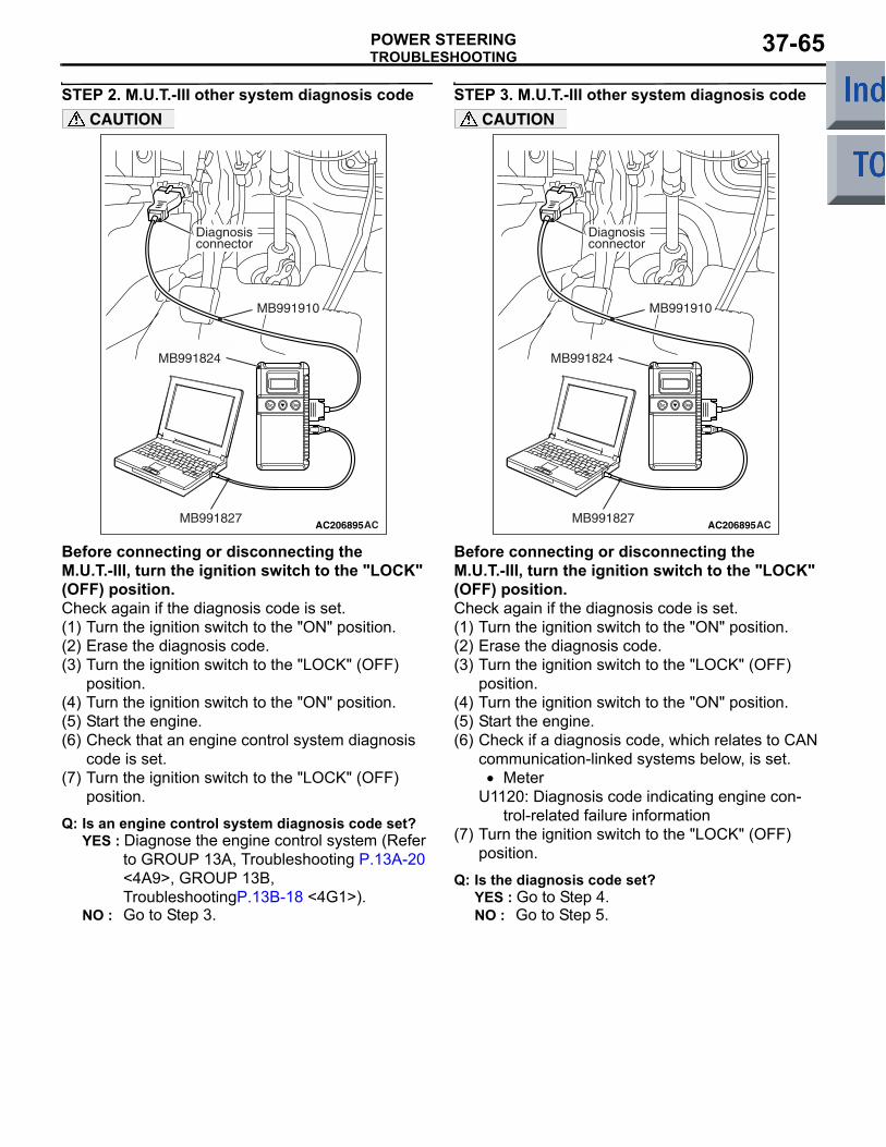
TROUBLESHOOTINGPOWER STEERING 37-65
STEP 2. M.U.T.-III other system diagnosis code
AC206895AC
Diagnosisconnector
MB991827
MB991824
MB991910
CAUTION
Before connecting or disconnecting the M.U.T.-III, turn the ignition switch to the "LOCK" (OFF) position.Check again if the diagnosis code is set.(1) Turn the ignition switch to the "ON" position.(2) Erase the diagnosis code.(3) Turn the ignition switch to the "LOCK" (OFF)
position.(4) Turn the ignition switch to the "ON" position.(5) Start the engine.(6) Check that an engine control system diagnosis
code is set.(7) Turn the ignition switch to the "LOCK" (OFF)
position.
Q: Is an engine control system diagnosis code set?YES : Diagnose the engine control system (Refer
to GROUP 13A, Troubleshooting P.13A-20 <4A9>, GROUP 13B, TroubleshootingP.13B-18 <4G1>).
NO : Go to Step 3.
STEP 3. M.U.T.-III other system diagnosis code
AC206895AC
Diagnosisconnector
MB991827
MB991824
MB991910
CAUTION
Before connecting or disconnecting the M.U.T.-III, turn the ignition switch to the "LOCK" (OFF) position.Check again if the diagnosis code is set.(1) Turn the ignition switch to the "ON" position.(2) Erase the diagnosis code.(3) Turn the ignition switch to the "LOCK" (OFF)
position.(4) Turn the ignition switch to the "ON" position.(5) Start the engine.(6) Check if a diagnosis code, which relates to CAN
communication-linked systems below, is set.• Meter
U1120: Diagnosis code indicating engine con-trol-related failure information
(7) Turn the ignition switch to the "LOCK" (OFF) position.
Q: Is the diagnosis code set?YES : Go to Step 4.NO : Go to Step 5.
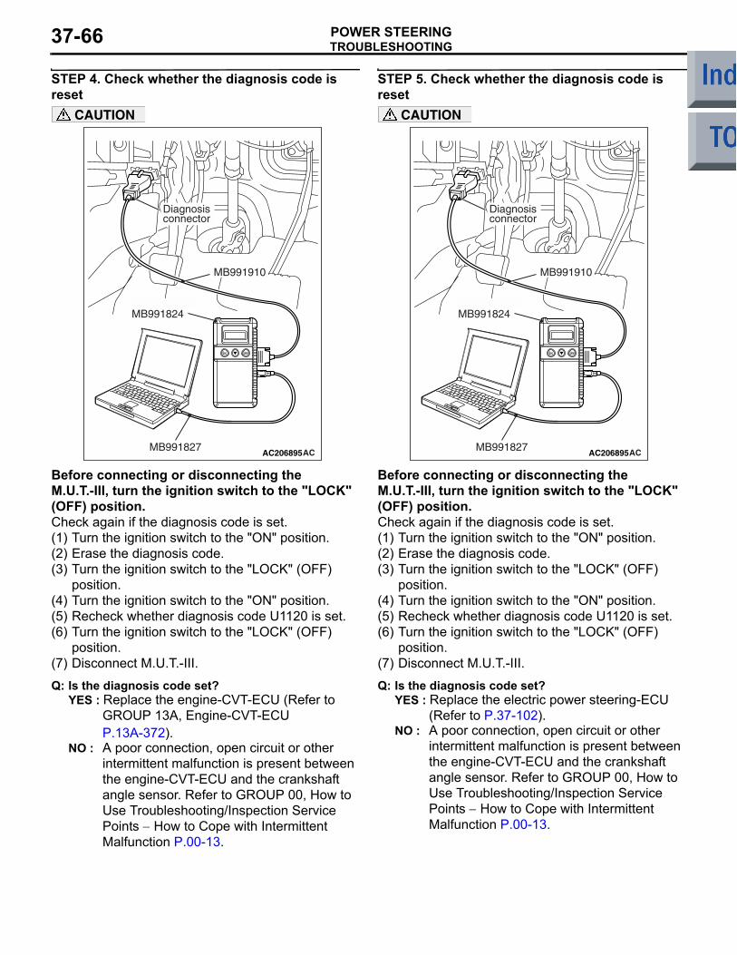
TROUBLESHOOTINGPOWER STEERING37-66
STEP 4. Check whether the diagnosis code is reset
AC206895AC
Diagnosisconnector
MB991827
MB991824
MB991910
CAUTION
Before connecting or disconnecting the M.U.T.-III, turn the ignition switch to the "LOCK" (OFF) position.Check again if the diagnosis code is set.(1) Turn the ignition switch to the "ON" position.(2) Erase the diagnosis code.(3) Turn the ignition switch to the "LOCK" (OFF)
position.(4) Turn the ignition switch to the "ON" position.(5) Recheck whether diagnosis code U1120 is set.(6) Turn the ignition switch to the "LOCK" (OFF)
position.(7) Disconnect M.U.T.-III.
Q: Is the diagnosis code set?YES : Replace the engine-CVT-ECU (Refer to
GROUP 13A, Engine-CVT-ECU P.13A-372).
NO : A poor connection, open circuit or other intermittent malfunction is present between the engine-CVT-ECU and the crankshaft angle sensor. Refer to GROUP 00, How to Use Troubleshooting/Inspection Service Points − How to Cope with Intermittent Malfunction P.00-13.
STEP 5. Check whether the diagnosis code is reset
AC206895AC
Diagnosisconnector
MB991827
MB991824
MB991910
CAUTION
Before connecting or disconnecting the M.U.T.-III, turn the ignition switch to the "LOCK" (OFF) position.Check again if the diagnosis code is set.(1) Turn the ignition switch to the "ON" position.(2) Erase the diagnosis code.(3) Turn the ignition switch to the "LOCK" (OFF)
position.(4) Turn the ignition switch to the "ON" position.(5) Recheck whether diagnosis code U1120 is set.(6) Turn the ignition switch to the "LOCK" (OFF)
position.(7) Disconnect M.U.T.-III.
Q: Is the diagnosis code set?YES : Replace the electric power steering-ECU
(Refer to P.37-102).NO : A poor connection, open circuit or other
intermittent malfunction is present between the engine-CVT-ECU and the crankshaft angle sensor. Refer to GROUP 00, How to Use Troubleshooting/Inspection Service Points − How to Cope with Intermittent Malfunction P.00-13.
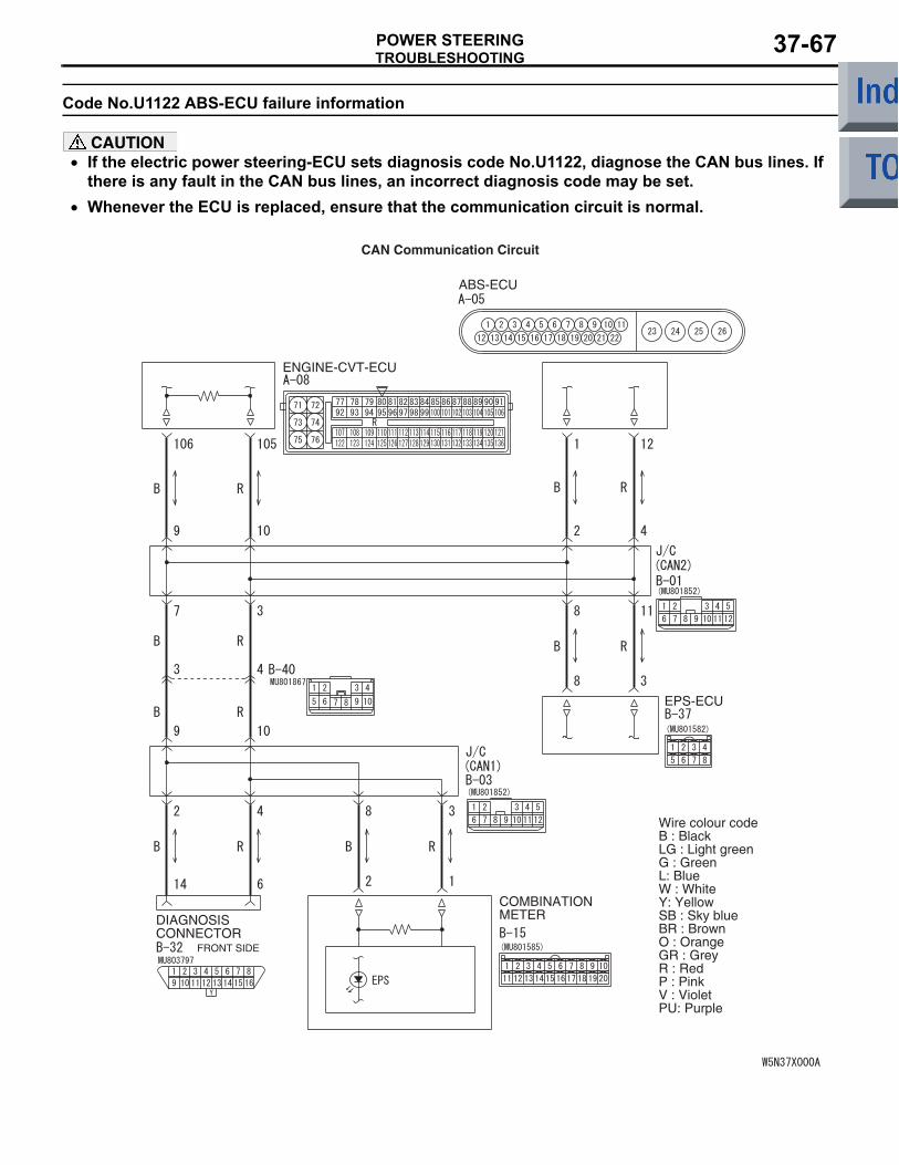
TROUBLESHOOTINGPOWER STEERING 37-67
Code No.U1122 ABS-ECU failure information
CAUTION• If the electric power steering-ECU sets diagnosis code No.U1122, diagnose the CAN bus lines. If
there is any fault in the CAN bus lines, an incorrect diagnosis code may be set.•
ENGINE-CVT-ECU
DIAGNOSISCONNECTOR
FRONT SIDE
COMBINATIONMETER
ABS-ECU
EPS-ECU
Wire colour codeB : BlackLG : Light greenG : GreenL: BlueW : WhiteY: YellowSB : Sky blueBR : BrownO : OrangeGR : GreyR : RedP : PinkV : VioletPU: Purple
CAN Communication Circuit
Whenever the ECU is replaced, ensure that the communication circuit is normal.
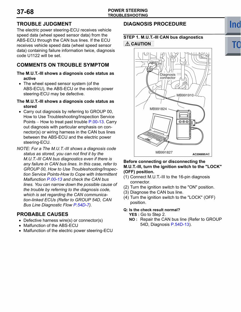
TROUBLESHOOTINGPOWER STEERING37-68
TROUBLE JUDGMENTThe electric power steering-ECU receives vehicle speed data (wheel speed sensor data) from the ABS-ECU through the CAN bus lines. If the ECU receives vehicle speed data (wheel speed sensor data) containing failure information twice, diagnosis code U1122 will be set.
COMMENTS ON TROUBLE SYMPTOMThe M.U.T.-III shows a diagnosis code status as
active• The wheel speed sensor system (of the
ABS-ECU), the ABS-ECU or the electric power steering-ECU may be defective.
The M.U.T.-III shows a diagnosis code status as stored
• Carry out diagnosis by referring to GROUP 00, How to Use Troubleshooting/Inspection Service Points − How to treat past trouble P.00-13. Carry out diagnosis with particular emphasis on con-nector(s) or wiring harness in the CAN bus lines between the ABS-ECU and the electric power steering-ECU.
NOTE: For a The M.U.T.-III shows a diagnosis code status as stored, you can not find it by the M.U.T.-III CAN bus diagnostics even if there is any failure in CAN bus lines. In this case, refer to GROUP 00, How to Use Troubleshooting/Inspec-tion Service Points-How to Cope with Intermittent Malfunction P.00-13 and check the CAN bus lines. You can narrow down the possible cause of the trouble by referring to the diagnosis code, which is set regarding the CAN communica-tion-linked ECUs (Refer to GROUP 54D, CAN Bus Line Diagnostic Flow P.54D-7).
PROBABLE CAUSES• Defective harness wire(s) or connector(s)• Malfunction of the ABS-ECU• Malfunction of the electric power steering-ECU
DIAGNOSIS PROCEDURE
STEP 1. M.U.T.-III CAN bus diagnostics
AC206895AC
Diagnosisconnector
MB991827
MB991824
MB991910
CAUTION
Before connecting or disconnecting the M.U.T.-III, turn the ignition switch to the "LOCK" (OFF) position.(1) Connect M.U.T.-III to the 16-pin diagnosis
connector.(2) Turn the ignition switch to the "ON" position.(3) Diagnose the CAN bus line.(4) Turn the ignition switch to the "LOCK" (OFF)
position.
Q: Is the check result normal?YES : Go to Step 2.NO : Repair the CAN bus line (Refer to GROUP
54D, Diagnosis P.54D-13).
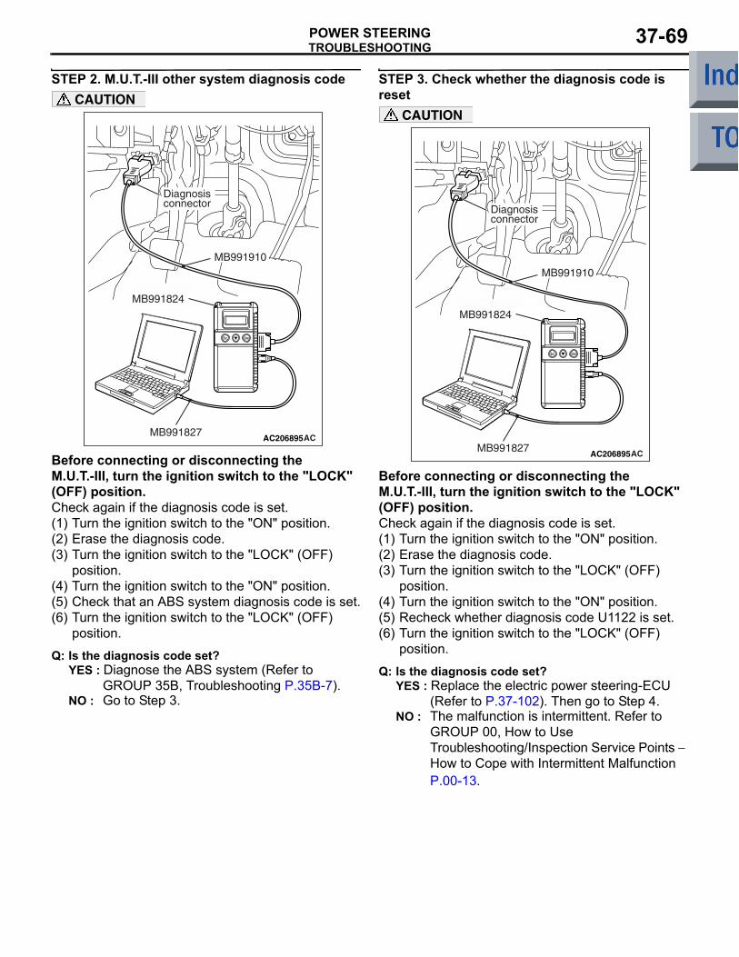
TROUBLESHOOTINGPOWER STEERING 37-69
STEP 2. M.U.T.-III other system diagnosis code
AC206895AC
Diagnosisconnector
MB991827
MB991824
MB991910
CAUTION
Before connecting or disconnecting the M.U.T.-III, turn the ignition switch to the "LOCK" (OFF) position.Check again if the diagnosis code is set.(1) Turn the ignition switch to the "ON" position.(2) Erase the diagnosis code.(3) Turn the ignition switch to the "LOCK" (OFF)
position.(4) Turn the ignition switch to the "ON" position.(5) Check that an ABS system diagnosis code is set.(6) Turn the ignition switch to the "LOCK" (OFF)
position.
Q: Is the diagnosis code set?YES : Diagnose the ABS system (Refer to
GROUP 35B, Troubleshooting P.35B-7).NO : Go to Step 3.
STEP 3. Check whether the diagnosis code is reset
AC206895AC
Diagnosisconnector
MB991827
MB991824
MB991910
CAUTION
Before connecting or disconnecting the M.U.T.-III, turn the ignition switch to the "LOCK" (OFF) position.Check again if the diagnosis code is set.(1) Turn the ignition switch to the "ON" position.(2) Erase the diagnosis code.(3) Turn the ignition switch to the "LOCK" (OFF)
position.(4) Turn the ignition switch to the "ON" position.(5) Recheck whether diagnosis code U1122 is set.(6) Turn the ignition switch to the "LOCK" (OFF)
position.
Q: Is the diagnosis code set?YES : Replace the electric power steering-ECU
(Refer to P.37-102). Then go to Step 4.NO : The malfunction is intermittent. Refer to
GROUP 00, How to Use Troubleshooting/Inspection Service Points − How to Cope with Intermittent Malfunction P.00-13.
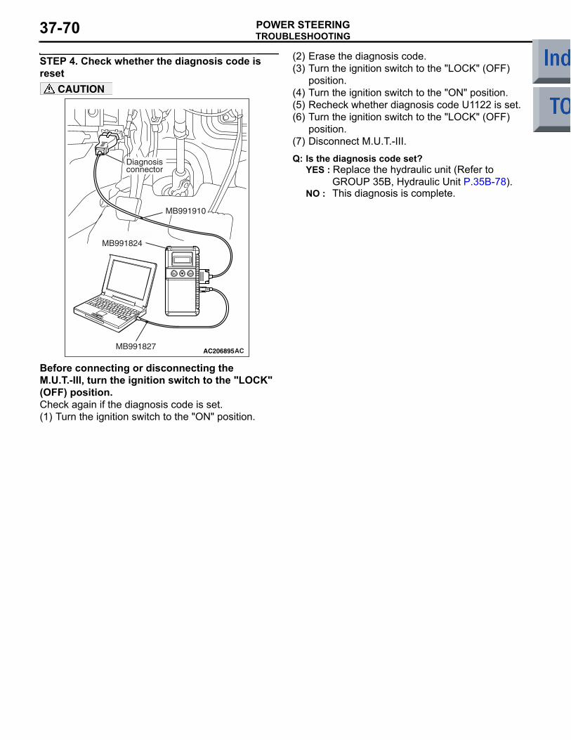
TROUBLESHOOTINGPOWER STEERING37-70
STEP 4. Check whether the diagnosis code is reset
AC206895AC
Diagnosisconnector
MB991827
MB991824
MB991910
CAUTION
Before connecting or disconnecting the M.U.T.-III, turn the ignition switch to the "LOCK" (OFF) position.Check again if the diagnosis code is set.(1) Turn the ignition switch to the "ON" position.
(2) Erase the diagnosis code.(3) Turn the ignition switch to the "LOCK" (OFF)
position.(4) Turn the ignition switch to the "ON" position.(5) Recheck whether diagnosis code U1122 is set.(6) Turn the ignition switch to the "LOCK" (OFF)
position.(7) Disconnect M.U.T.-III.
Q: Is the diagnosis code set?YES : Replace the hydraulic unit (Refer to
GROUP 35B, Hydraulic Unit P.35B-78). NO : This diagnosis is complete.
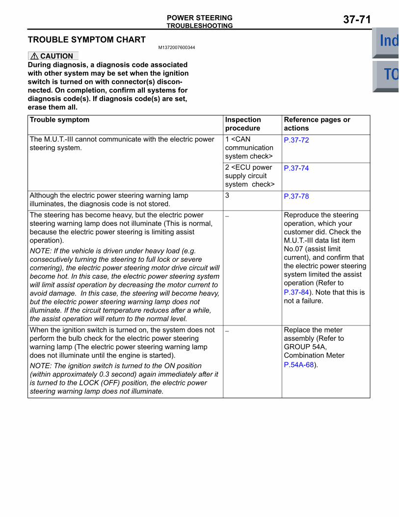
TROUBLESHOOTINGPOWER STEERING 37-71
TROUBLE SYMPTOM CHARTM1372007600344
CAUTIONDuring diagnosis, a diagnosis code associated with other system may be set when the ignition switch is turned on with connector(s) discon-nected. On completion, confirm all systems for diagnosis code(s). If diagnosis code(s) are set, erase them all.Trouble symptom Inspection
procedureReference pages or actions
The M.U.T.-III cannot communicate with the electric power steering system.
1 <CAN communication system check>
P.37-72
2 <ECU power supply circuit system check>
P.37-74
Although the electric power steering warning lamp illuminates, the diagnosis code is not stored.
3 P.37-78
The steering has become heavy, but the electric power steering warning lamp does not illuminate (This is normal, because the electric power steering is limiting assist operation).NOTE: If the vehicle is driven under heavy load (e.g. consecutively turning the steering to full lock or severe cornering), the electric power steering motor drive circuit will become hot. In this case, the electric power steering system will limit assist operation by decreasing the motor current to avoid damage. In this case, the steering will become heavy, but the electric power steering warning lamp does not illuminate. If the circuit temperature reduces after a while, the assist operation will return to the normal level.
− Reproduce the steering operation, which your customer did. Check the M.U.T.-III data list item No.07 (assist limit current), and confirm that the electric power steering system limited the assist operation (Refer to P.37-84). Note that this is not a failure.
When the ignition switch is turned on, the system does not perform the bulb check for the electric power steering warning lamp (The electric power steering warning lamp does not illuminate until the engine is started).NOTE: The ignition switch is turned to the ON position (within approximately 0.3 second) again immediately after it is turned to the LOCK (OFF) position, the electric power steering warning lamp does not illuminate.
− Replace the meter assembly (Refer to GROUP 54A, Combination Meter P.54A-68).
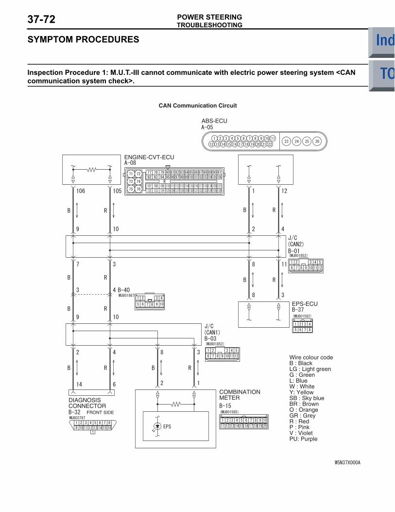
TROUBLESHOOTINGPOWER STEERING37-72
SYMPTOM PROCEDURES
Inspection Procedure 1: M.U.T.-III cannot communicate with electric power steering system <CAN communication system check>.
ENGINE-CVT-ECU
DIAGNOSISCONNECTOR
FRONT SIDE
COMBINATIONMETER
ABS-ECU
EPS-ECU
Wire colour codeB : BlackLG : Light greenG : GreenL: BlueW : WhiteY: YellowSB : Sky blueBR : BrownO : OrangeGR : GreyR : RedP : PinkV : VioletPU: Purple
CAN Communication Circuit
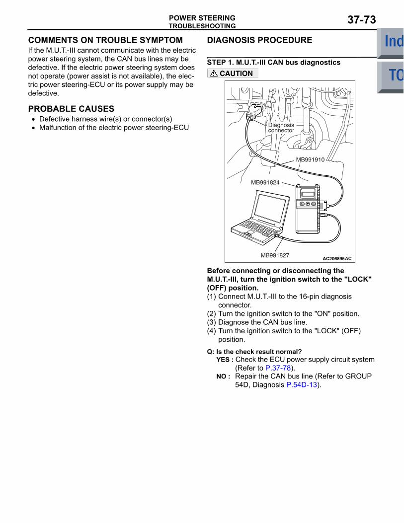
TROUBLESHOOTINGPOWER STEERING 37-73
COMMENTS ON TROUBLE SYMPTOMIf the M.U.T.-III cannot communicate with the electric power steering system, the CAN bus lines may be defective. If the electric power steering system does not operate (power assist is not available), the elec-tric power steering-ECU or its power supply may be defective.
PROBABLE CAUSES• Defective harness wire(s) or connector(s)• Malfunction of the electric power steering-ECU
DIAGNOSIS PROCEDURE
STEP 1. M.U.T.-III CAN bus diagnostics
AC206895AC
Diagnosisconnector
MB991827
MB991824
MB991910
CAUTION
Before connecting or disconnecting the M.U.T.-III, turn the ignition switch to the "LOCK" (OFF) position.(1) Connect M.U.T.-III to the 16-pin diagnosis
connector.(2) Turn the ignition switch to the "ON" position.(3) Diagnose the CAN bus line.(4) Turn the ignition switch to the "LOCK" (OFF)
position.
Q: Is the check result normal?YES : Check the ECU power supply circuit system
(Refer to P.37-78).NO : Repair the CAN bus line (Refer to GROUP
54D, Diagnosis P.54D-13).
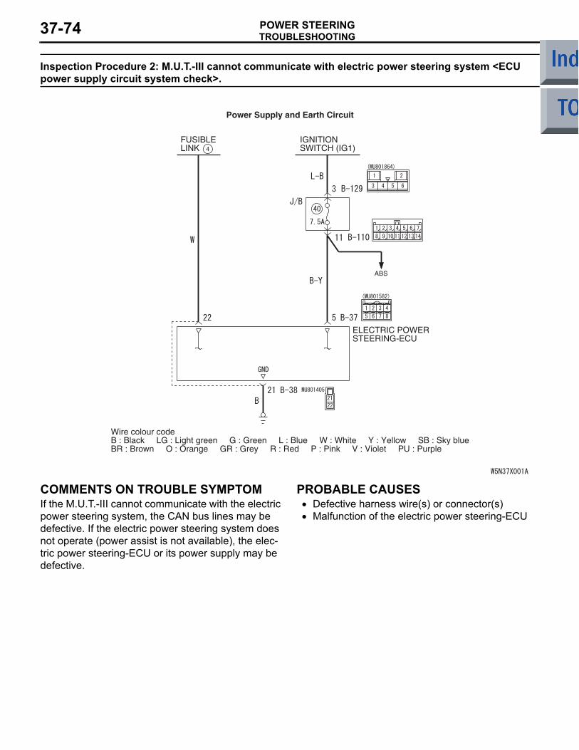
TROUBLESHOOTINGPOWER STEERING37-74
Inspection Procedure 2: M.U.T.-III cannot communicate with electric power steering system <ECU power supply circuit system check>.
Power Supply and Earth Circuit
FUSIBLELINK
IGNITIONSWITCH (IG1)4
ABS
ELECTRIC POWERSTEERING-ECU
Wire colour codeB : Black LG : Light green G : Green L : Blue W : White Y : Yellow SB : Sky blueBR : Brown O : Orange GR : Grey R : Red P : Pink V : Violet PU : Purple
COMMENTS ON TROUBLE SYMPTOMIf the M.U.T.-III cannot communicate with the electric power steering system, the CAN bus lines may be defective. If the electric power steering system does not operate (power assist is not available), the elec-tric power steering-ECU or its power supply may be defective.
PROBABLE CAUSES• Defective harness wire(s) or connector(s)• Malfunction of the electric power steering-ECU
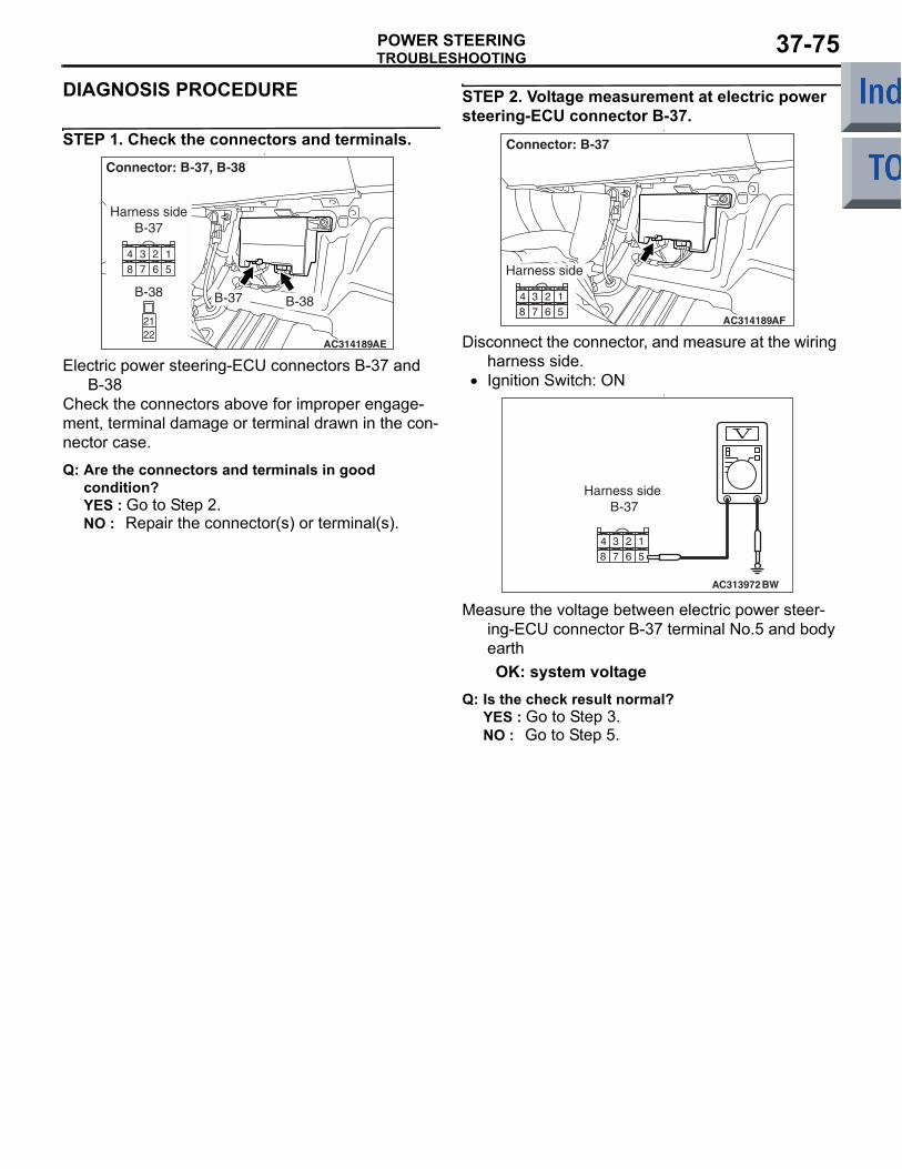
TROUBLESHOOTINGPOWER STEERING 37-75
DIAGNOSIS PROCEDURE
STEP 1. Check the connectors and terminals.•
AC314189AE
Connector: B-37, B-38
B-37 B-38
Harness sideB-37
2122
B-38
Electric power steering-ECU connectors B-37 and B-38
Check the connectors above for improper engage-ment, terminal damage or terminal drawn in the con-nector case.
Q: Are the connectors and terminals in good condition?YES : Go to Step 2.NO : Repair the connector(s) or terminal(s).
STEP 2. Voltage measurement at electric power steering-ECU connector B-37.
•
AC314189AF
Connector: B-37
Harness side
Disconnect the connector, and measure at the wiring harness side.
• Ignition Switch: ON•
AC313972BW
Harness side B-37
Measure the voltage between electric power steer-ing-ECU connector B-37 terminal No.5 and body earthOK: system voltage
Q: Is the check result normal?YES : Go to Step 3.NO : Go to Step 5.
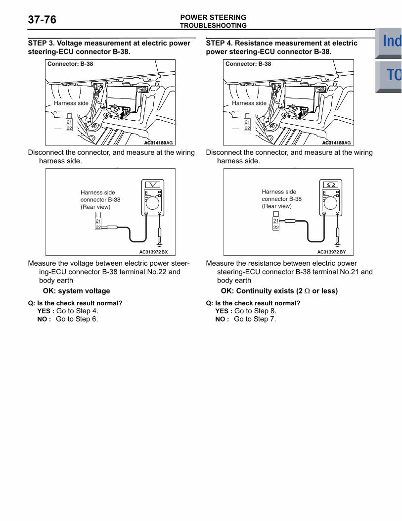
TROUBLESHOOTINGPOWER STEERING37-76
STEP 3. Voltage measurement at electric power steering-ECU connector B-38.
•
AC314189AC314189AC314189AG
Connector: B-38
Harness side
Disconnect the connector, and measure at the wiring harness side.
•
AC313972BX
Harness sideconnector B-38(Rear view)
Measure the voltage between electric power steer-ing-ECU connector B-38 terminal No.22 and body earthOK: system voltage
Q: Is the check result normal?YES : Go to Step 4.NO : Go to Step 6.
STEP 4. Resistance measurement at electric power steering-ECU connector B-38.
•
AC314189AC314189AC314189AG
Connector: B-38
Harness side
Disconnect the connector, and measure at the wiring harness side.
•
AC313972BY
Harness sideconnector B-38(Rear view)
Measure the resistance between electric power steering-ECU connector B-38 terminal No.21 and body earthOK: Continuity exists (2 Ω or less)
Q: Is the check result normal?YES : Go to Step 8.NO : Go to Step 7.
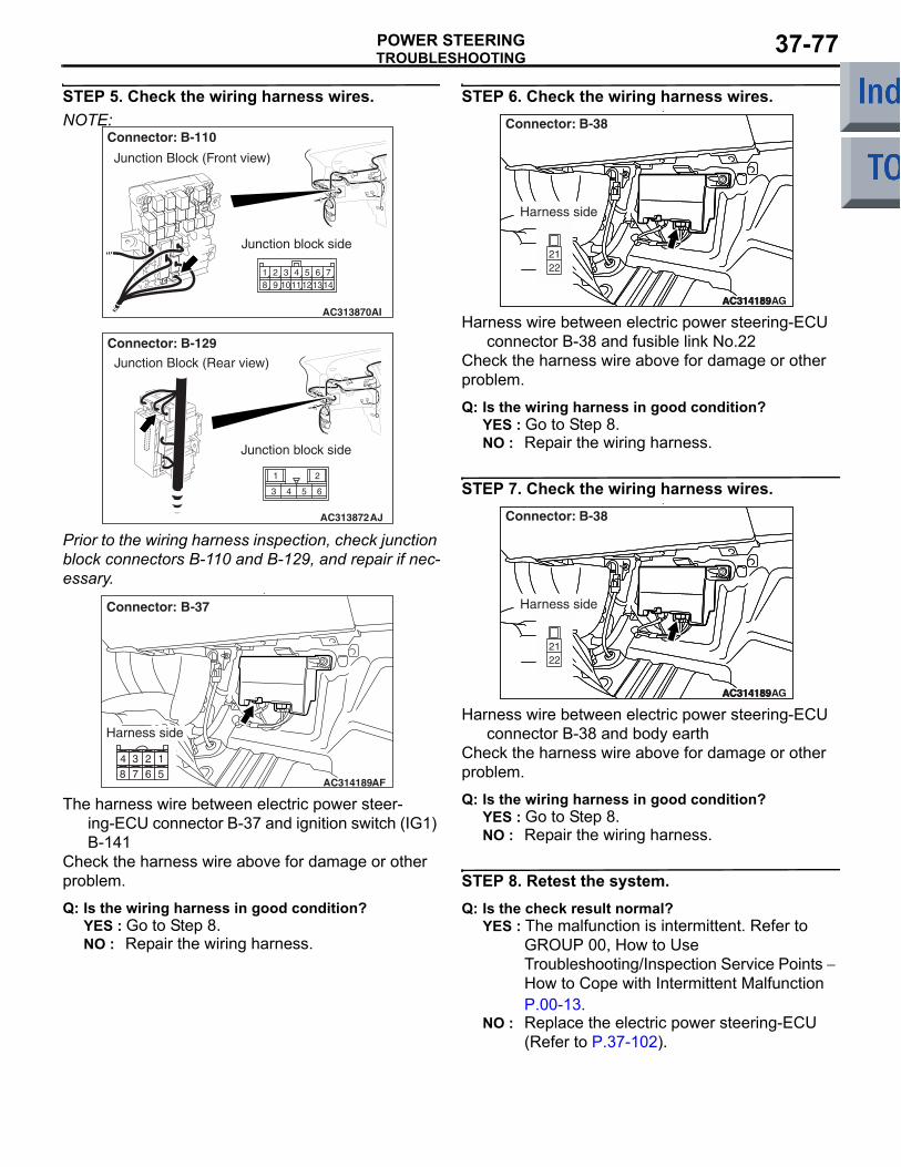
TROUBLESHOOTINGPOWER STEERING 37-77
STEP 5. Check the wiring harness wires.NOTE:
AC313870AI
Connector: B-110
Junction Block (Front view)
Junction block side
125
981 2
10113 4
14136 7
AC313872AJ
Connector: B-129Junction Block (Rear view)
Junction block side
Prior to the wiring harness inspection, check junction block connectors B-110 and B-129, and repair if nec-essary.
•
AC314189AF
Connector: B-37
Harness side
The harness wire between electric power steer-ing-ECU connector B-37 and ignition switch (IG1) B-141
Check the harness wire above for damage or other problem.
Q: Is the wiring harness in good condition?YES : Go to Step 8.NO : Repair the wiring harness.
STEP 6. Check the wiring harness wires.•
AC314189AC314189AC314189AG
Connector: B-38
Harness side
Harness wire between electric power steering-ECU connector B-38 and fusible link No.22
Check the harness wire above for damage or other problem.
Q: Is the wiring harness in good condition?YES : Go to Step 8.NO : Repair the wiring harness.
STEP 7. Check the wiring harness wires.•
AC314189AC314189AC314189AG
Connector: B-38
Harness side
Harness wire between electric power steering-ECU connector B-38 and body earth
Check the harness wire above for damage or other problem.
Q: Is the wiring harness in good condition?YES : Go to Step 8.NO : Repair the wiring harness.
STEP 8. Retest the system.Q: Is the check result normal?
YES : The malfunction is intermittent. Refer to GROUP 00, How to Use Troubleshooting/Inspection Service Points − How to Cope with Intermittent Malfunction P.00-13.
NO : Replace the electric power steering-ECU (Refer to P.37-102).
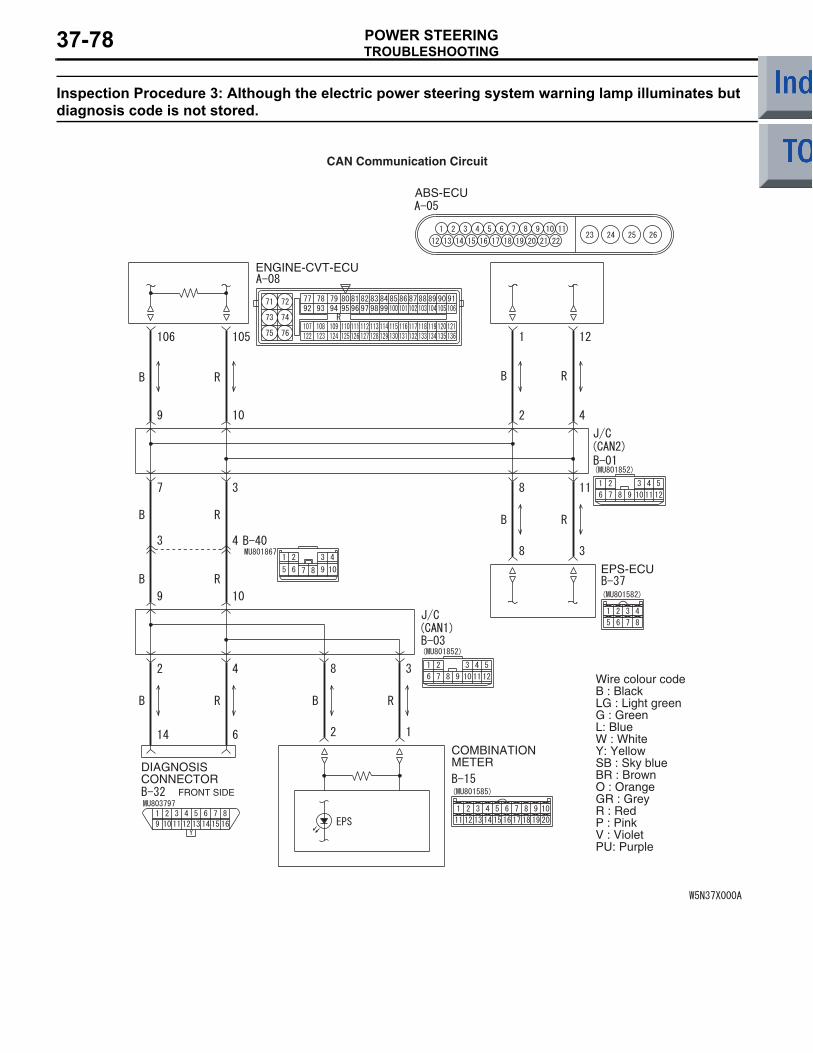
TROUBLESHOOTINGPOWER STEERING37-78
Inspection Procedure 3: Although the electric power steering system warning lamp illuminates but diagnosis code is not stored.
ENGINE-CVT-ECU
DIAGNOSISCONNECTOR
FRONT SIDE
COMBINATIONMETER
ABS-ECU
EPS-ECU
Wire colour codeB : BlackLG : Light greenG : GreenL: BlueW : WhiteY: YellowSB : Sky blueBR : BrownO : OrangeGR : GreyR : RedP : PinkV : VioletPU: Purple
CAN Communication Circuit
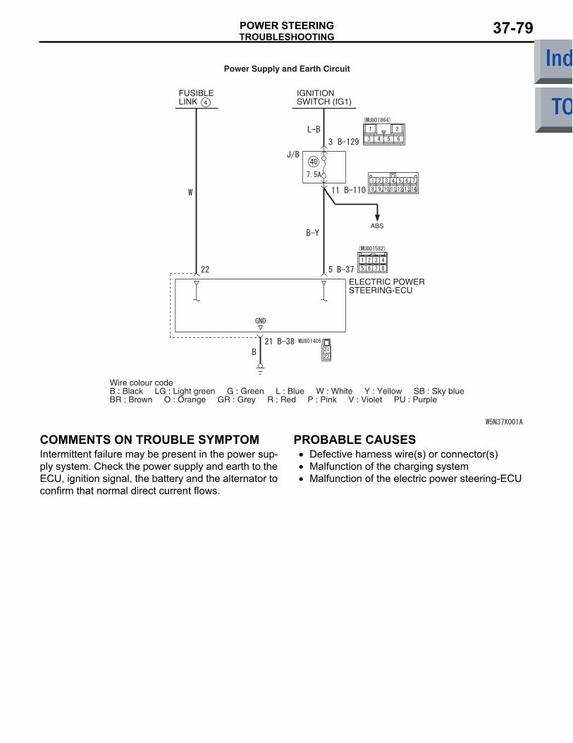
TROUBLESHOOTINGPOWER STEERING 37-79
Power Supply and Earth Circuit
FUSIBLELINK
IGNITIONSWITCH (IG1)4
ABS
ELECTRIC POWERSTEERING-ECU
Wire colour codeB : Black LG : Light green G : Green L : Blue W : White Y : Yellow SB : Sky blueBR : Brown O : Orange GR : Grey R : Red P : Pink V : Violet PU : Purple
COMMENTS ON TROUBLE SYMPTOMIntermittent failure may be present in the power sup-ply system. Check the power supply and earth to the ECU, ignition signal, the battery and the alternator to confirm that normal direct current flows.
PROBABLE CAUSES• Defective harness wire(s) or connector(s)• Malfunction of the charging system• Malfunction of the electric power steering-ECU
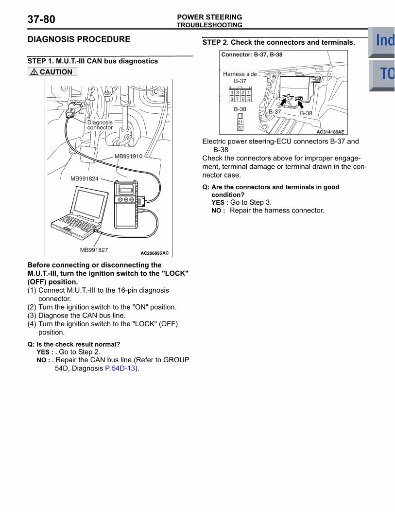
TROUBLESHOOTINGPOWER STEERING37-80
DIAGNOSIS PROCEDURE
STEP 1. M.U.T.-III CAN bus diagnostics
AC206895AC
Diagnosisconnector
MB991827
MB991824
MB991910
CAUTION
Before connecting or disconnecting the M.U.T.-III, turn the ignition switch to the "LOCK" (OFF) position.(1) Connect M.U.T.-III to the 16-pin diagnosis
connector.(2) Turn the ignition switch to the "ON" position.(3) Diagnose the CAN bus line.(4) Turn the ignition switch to the "LOCK" (OFF)
position.
Q: Is the check result normal?YES : . Go to Step 2.NO : . Repair the CAN bus line (Refer to GROUP
54D, Diagnosis P.54D-13).
STEP 2. Check the connectors and terminals.•
AC314189AE
Connector: B-37, B-38
B-37 B-38
Harness sideB-37
2122
B-38
Electric power steering-ECU connectors B-37 and B-38
Check the connectors above for improper engage-ment, terminal damage or terminal drawn in the con-nector case.
Q: Are the connectors and terminals in good condition?YES : Go to Step 3.NO : Repair the harness connector.
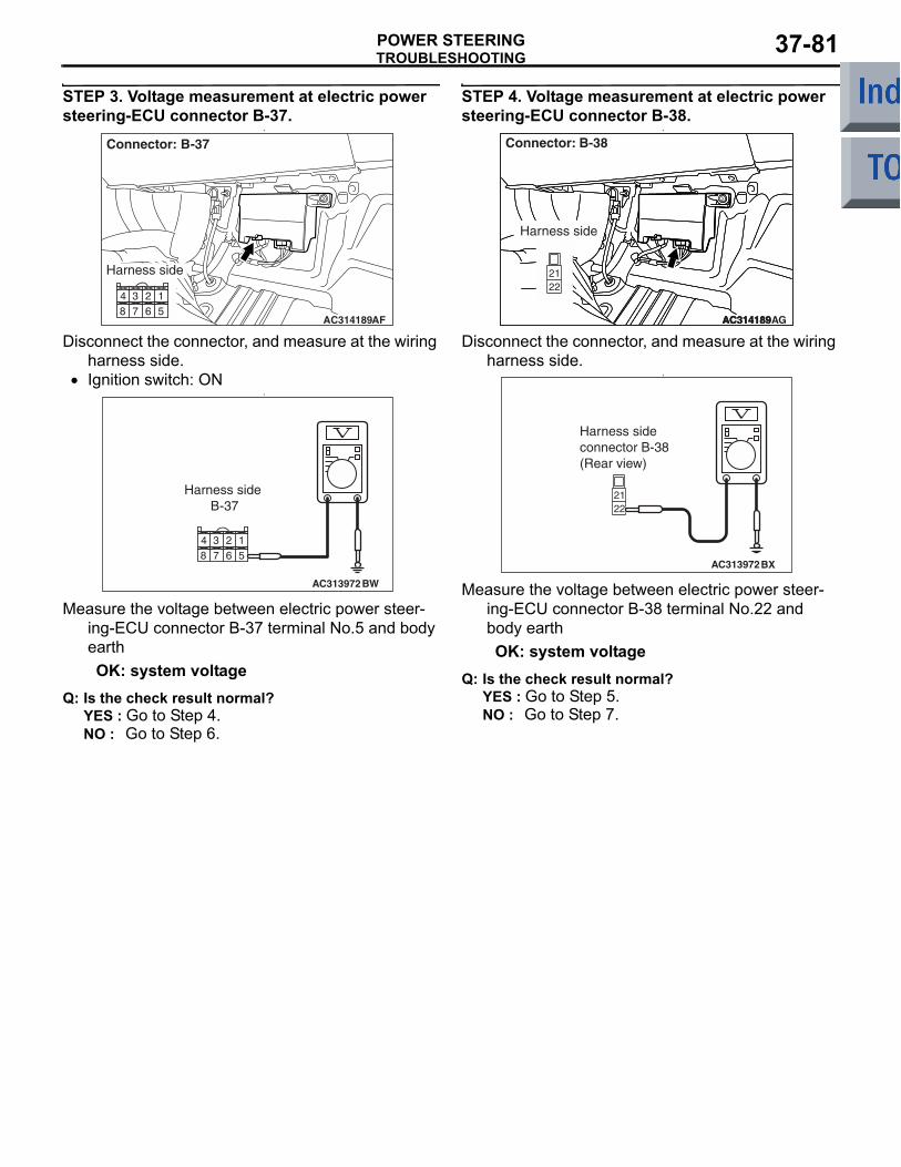
TROUBLESHOOTINGPOWER STEERING 37-81
STEP 3. Voltage measurement at electric power steering-ECU connector B-37.
•
AC314189AF
Connector: B-37
Harness side
Disconnect the connector, and measure at the wiring harness side.
• Ignition switch: ON•
AC313972BW
Harness side B-37
Measure the voltage between electric power steer-ing-ECU connector B-37 terminal No.5 and body earthOK: system voltage
Q: Is the check result normal?YES : Go to Step 4.NO : Go to Step 6.
STEP 4. Voltage measurement at electric power steering-ECU connector B-38.
•
AC314189AC314189AC314189AG
Connector: B-38
Harness side
Disconnect the connector, and measure at the wiring harness side.
•
AC313972BX
Harness sideconnector B-38(Rear view)
Measure the voltage between electric power steer-ing-ECU connector B-38 terminal No.22 and body earthOK: system voltage
Q: Is the check result normal?YES : Go to Step 5.NO : Go to Step 7.
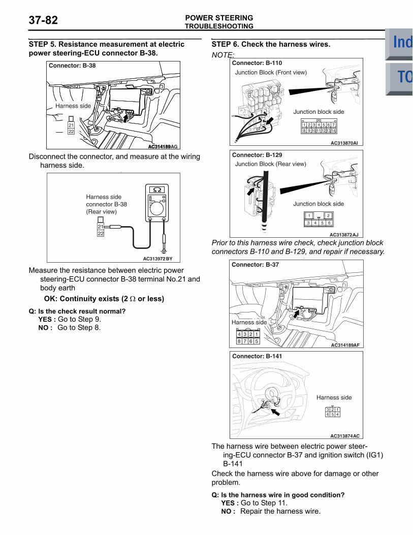
TROUBLESHOOTINGPOWER STEERING37-82
STEP 5. Resistance measurement at electric power steering-ECU connector B-38.
•
AC314189AC314189AC314189AG
Connector: B-38
Harness side
Disconnect the connector, and measure at the wiring harness side.
•
AC313972BY
Harness sideconnector B-38(Rear view)
Measure the resistance between electric power steering-ECU connector B-38 terminal No.21 and body earthOK: Continuity exists (2 Ω or less)
Q: Is the check result normal?YES : Go to Step 9.NO : Go to Step 8.
STEP 6. Check the harness wires.NOTE:
AC313870AI
Connector: B-110
Junction Block (Front view)
Junction block side
125
981 2
10113 4
14136 7
AC313872AJ
Connector: B-129Junction Block (Rear view)
Junction block side
Prior to this harness wire check, check junction block connectors B-110 and B-129, and repair if necessary.
•
AC314189AF
Connector: B-37
Harness side
AC313874AC
Connector: B-141
Harness side
The harness wire between electric power steer-ing-ECU connector B-37 and ignition switch (IG1) B-141
Check the harness wire above for damage or other problem.
Q: Is the harness wire in good condition?YES : Go to Step 11.NO : Repair the harness wire.
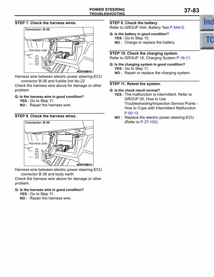
TROUBLESHOOTINGPOWER STEERING 37-83
STEP 7. Check the harness wires.•
AC314189AC314189AC314189AG
Connector: B-38
Harness side
Harness wire between electric power steering-ECU connector B-38 and fusible link No.22
Check the harness wire above for damage or other problem.
Q: Is the harness wire in good condition?YES : Go to Step 11.NO : Repair the harness wire.
STEP 8. Check the harness wires.•
AC314189AC314189AC314189AG
Connector: B-38
Harness side
Harness wire between electric power steering-ECU connector B-38 and body earth
Check the harness wire above for damage or other problem.
Q: Is the harness wire in good condition?YES : Go to Step 11.NO : Repair the harness wire.
STEP 9. Check the batteryRefer to GROUP 54A, Battery Test P.54A-5.
Q: Is the battery in good condition?YES : Go to Step 10.NO : Charge or replace the battery.
STEP 10. Check the charging system.Refer to GROUP 16, Charging System P.16-11.
Q: Is the charging system in good condition?YES : Go to Step 11.NO : Repair or replace the charging system.
STEP 11. Retest the system.Q: Is the check result normal?
YES : The malfunction is intermittent. Refer to GROUP 00, How to Use Troubleshooting/Inspection Service Points − How to Cope with Intermittent Malfunction P.00-13.
NO : Replace the electric power steering-ECU (Refer to P.37-102).
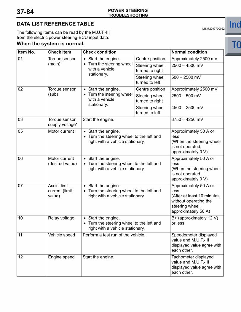
TROUBLESHOOTINGPOWER STEERING37-84
DATA LIST REFERENCE TABLEM1372007700062
The following items can be read by the M.U.T.-III from the electric power steering-ECU input data.When the system is normal.Item No. Check item Check condition Normal condition01 Torque sensor
(main)• Start the engine.• Turn the steering wheel
with a vehicle stationary.
Centre position Approximately 2500 mVSteering wheel turned to right
2500 − 4500 mV
Steering wheel turned to left
500 − 2500 mV
02 Torque sensor (sub)
• Start the engine.• Turn the steering wheel
with a vehicle stationary.
Centre position Approximately 2500 mVSteering wheel turned to right
2500 − 500 mV
Steering wheel turned to left
4500 − 2500 mV
03 Torque sensor supply voltage*
Start the engine. 3750 − 4250 mV
05 Motor current • Start the engine.• Turn the steering wheel to the left and
right with a vehicle stationary.
Approximately 50 A or less(When the steering wheel is not operated, approximately 0 V)
06 Motor current (desired value)
• Start the engine.• Turn the steering wheel to the left and
right with a vehicle stationary.
Approximately 50 A or less(When the steering wheel is not operated, approximately 0 V)
07 Assist limit current (limit value)
• Start the engine.• Turn the steering wheel to the left and
right with a vehicle stationary.
Approximately 50 A or less(After at least 10 minutes without operating the steering wheel, approximately 50 A)
10 Relay voltage • Start the engine.• Turn the steering wheel to the left and
right with a vehicle stationary.
B+ (approximately 12 V) or less
11 Vehicle speed Perform a test run of the vehicle. Speedometer displayed value and M.U.T.-III displayed value agree with each other.
12 Engine speed Start the engine. Tachometer displayed value and M.U.T.-III displayed value agree with each other.
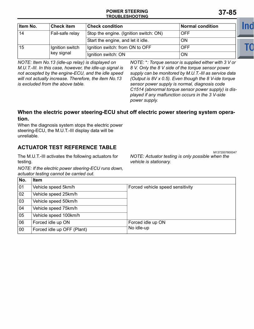
TROUBLESHOOTINGPOWER STEERING 37-85
NOTE: Item No.13 (idle-up relay) is displayed on M.U.T.-III. In this case, however, the idle-up signal is not accepted by the engine-ECU, and the idle speed will not actually increase. Therefore, the item No.13 is excluded from the above table.
NOTE: *: Torque sensor is supplied either with 3 V or 8 V. Only the 8 V side of the torque sensor power supply can be monitored by M.U.T.-III as service data (Output is 8V x 0.5). Even though the 8 V-ide torque sensor power supply is normal, diagnosis code C1514 (abnormal torque sensor power supply) is dis-played if any malfunction occurs in the 3 V-side power supply.
When the electric power steering-ECU shut off electric power steering system opera-tion.When the diagnosis system stops the electric power steering-ECU, the M.U.T.-III display data will be unreliable.
ACTUATOR TEST REFERENCE TABLEM1372007800047
The M.U.T.-III activates the following actuators for testing.NOTE: If the electric power steering-ECU runs down, actuator testing cannot be carried out.
NOTE: Actuator testing is only possible when the vehicle is stationary.
No. Item01 Vehicle speed 5km/h Forced vehicle speed sensitivity02 Vehicle speed 25km/h03 Vehicle speed 50km/h04 Vehicle speed 75km/h05 Vehicle speed 100km/h06 Forced idle up ON Forced idle up ON
No idle-up00 Forced idle up OFF (Plant)
14 Fail-safe relay Stop the engine. (Ignition switch: ON) OFFStart the engine, and let it idle. ON
15 Ignition switch key signal
Ignition switch: from ON to OFF OFFIgnition switch: ON ON
Item No. Check item Check condition Normal condition
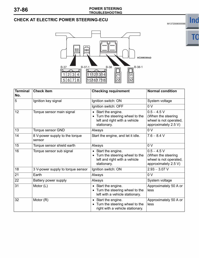
TROUBLESHOOTINGPOWER STEERING37-86
CHECK AT ELECTRIC POWER STEERING-ECUM1372008000066
AC208338
1 25 6
3 487
11121516
13141817
2122
3132
AD
B-37 B-37-1 B-38 B-38-1
Terminal No.
Check item Checking requirement Normal condition
5 Ignition key signal Ignition switch: ON System voltageIgnition switch: OFF 0 V
12 Torque sensor main signal • Start the engine.• Turn the steering wheel to the
left and right with a vehicle stationary.
0.5 − 4.5 V(When the steering wheel is not operated, approximately 2.5 V)
13 Torque sensor GND Always 0 V14 8 V-power supply to the torque
sensorStart the engine, and let it idle. 7.6 − 8.4 V
15 Torque sensor shield earth Always 0 V16 Torque sensor sub signal • Start the engine.
• Turn the steering wheel to the left and right with a vehicle stationary.
0.5 − 4.5 V(When the steering wheel is not operated, approximately 2.5 V)
18 3 V-power supply to torque sensor Ignition switch: ON 2.93 − 3.07 V21 Earth Always 0 V22 Battery power supply Always System voltage31 Motor (L) • Start the engine.
• Turn the steering wheel to the left with a vehicle stationary.
Approximately 50 A or less
32 Motor (R) • Start the engine.• Turn the steering wheel to the
right with a vehicle stationary.
Approximately 50 A or less
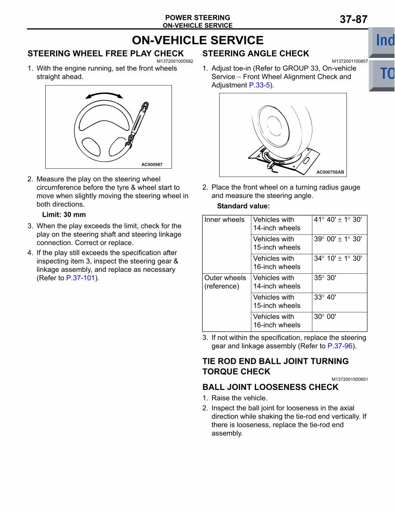
ON-VEHICLE SERVICEPOWER STEERING 37-87
ON-VEHICLE SERVICESTEERING WHEEL FREE PLAY CHECK
M1372001000582
1. With the engine running, set the front wheels straight ahead.
AC000987
2. Measure the play on the steering wheel circumference before the tyre & wheel start to move when slightly moving the steering wheel in both directions.
Limit: 30 mm3. When the play exceeds the limit, check for the
play on the steering shaft and steering linkage connection. Correct or replace.
4. If the play still exceeds the specification after inspecting item 3, inspect the steering gear & linkage assembly, and replace as necessary (Refer to P.37-101).
STEERING ANGLE CHECKM1372001100857
1. Adjust toe-in (Refer to GROUP 33, On-vehicle Service − Front Wheel Alignment Check and Adjustment P.33-5).
AC000756AB
2. Place the front wheel on a turning radius gauge and measure the steering angle.
Standard value:
Inner wheels Vehicles with 14-inch wheels
41° 40' ± 1° 30'
Vehicles with 15-inch wheels
39° 00' ± 1° 30'
Vehicles with 16-inch wheels
34° 10' ± 1° 30'
Outer wheels (reference)
Vehicles with 14-inch wheels
35° 30'
Vehicles with 15-inch wheels
33° 40'
Vehicles with 16-inch wheels
30° 00'
3. If not within the specification, replace the steering gear and linkage assembly (Refer to P.37-96).
TIE ROD END BALL JOINT TURNING TORQUE CHECK
M1372001500651
BALL JOINT LOOSENESS CHECK1. Raise the vehicle.2. Inspect the ball joint for looseness in the axial
direction while shaking the tie-rod end vertically. If there is looseness, replace the tie-rod end assembly.
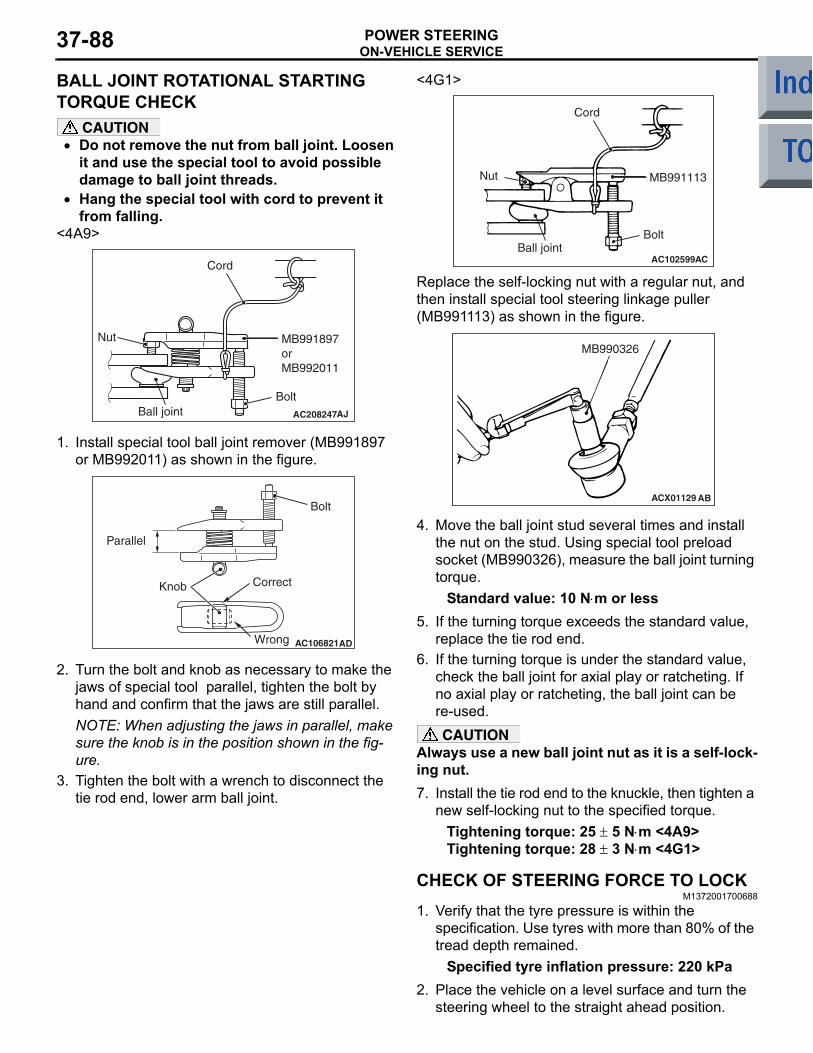
ON-VEHICLE SERVICEPOWER STEERING37-88
BALL JOINT ROTATIONAL STARTING TORQUE CHECK
CAUTION• Do not remove the nut from ball joint. Loosen
it and use the special tool to avoid possible damage to ball joint threads.
• Hang the special tool with cord to prevent it from falling.
<4A9>
AC208247AJ
Cord
Bolt
MB991897orMB992011
Nut
Ball joint
1. Install special tool ball joint remover (MB991897 or MB992011) as shown in the figure.
AC106821
Knob
Parallel
Bolt
Correct
Wrong AD
2. Turn the bolt and knob as necessary to make the jaws of special tool parallel, tighten the bolt by hand and confirm that the jaws are still parallel.NOTE: When adjusting the jaws in parallel, make sure the knob is in the position shown in the fig-ure.
3. Tighten the bolt with a wrench to disconnect the tie rod end, lower arm ball joint.
<4G1>
AC102599AC
Cord
Bolt
MB991113Nut
Ball joint
Replace the self-locking nut with a regular nut, and then install special tool steering linkage puller (MB991113) as shown in the figure.
ACX01129 AB
MB990326
4. Move the ball joint stud several times and install the nut on the stud. Using special tool preload socket (MB990326), measure the ball joint turning torque.
Standard value: 10 N⋅m or less5. If the turning torque exceeds the standard value,
replace the tie rod end.6. If the turning torque is under the standard value,
check the ball joint for axial play or ratcheting. If no axial play or ratcheting, the ball joint can be re-used.CAUTION
Always use a new ball joint nut as it is a self-lock-ing nut.7. Install the tie rod end to the knuckle, then tighten a
new self-locking nut to the specified torque.Tightening torque: 25 ± 5 N⋅m <4A9>Tightening torque: 28 ± 3 N⋅m <4G1>
CHECK OF STEERING FORCE TO LOCKM1372001700688
1. Verify that the tyre pressure is within the specification. Use tyres with more than 80% of the tread depth remained.
Specified tyre inflation pressure: 220 kPa2. Place the vehicle on a level surface and turn the
steering wheel to the straight ahead position.
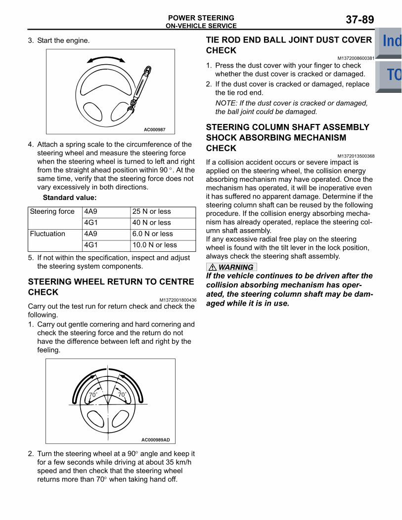
ON-VEHICLE SERVICEPOWER STEERING 37-89
3. Start the engine.
AC000987
4. Attach a spring scale to the circumference of the steering wheel and measure the steering force when the steering wheel is turned to left and right from the straight ahead position within 90 °. At the same time, verify that the steering force does not vary excessively in both directions.
Standard value:
Steering force 4A9 25 N or less 4G1 40 N or less
Fluctuation 4A9 6.0 N or less4G1 10.0 N or less
5. If not within the specification, inspect and adjust the steering system components.
STEERING WHEEL RETURN TO CENTRE CHECK
M1372001800436Carry out the test run for return check and check the following.1. Carry out gentle cornering and hard cornering and
check the steering force and the return do not have the difference between left and right by the feeling.
AC000989
70˚
AD
70˚
2. Turn the steering wheel at a 90° angle and keep it for a few seconds while driving at about 35 km/h speed and then check that the steering wheel returns more than 70° when taking hand off.
TIE ROD END BALL JOINT DUST COVER CHECK
M1372008600381
1. Press the dust cover with your finger to check whether the dust cover is cracked or damaged.
2. If the dust cover is cracked or damaged, replace the tie rod end.NOTE: If the dust cover is cracked or damaged, the ball joint could be damaged.
STEERING COLUMN SHAFT ASSEMBLY SHOCK ABSORBING MECHANISM CHECK
M1372013500368If a collision accident occurs or severe impact is applied on the steering wheel, the collision energy absorbing mechanism may have operated. Once the mechanism has operated, it will be inoperative even it has suffered no apparent damage. Determine if the steering column shaft can be reused by the following procedure. If the collision energy absorbing mecha-nism has already operated, replace the steering col-umn shaft assembly.If any excessive radial free play on the steering wheel is found with the tilt lever in the lock position, always check the steering shaft assembly.
WARNINGIf the vehicle continues to be driven after the collision absorbing mechanism has oper-ated, the steering column shaft may be dam-aged while it is in use.
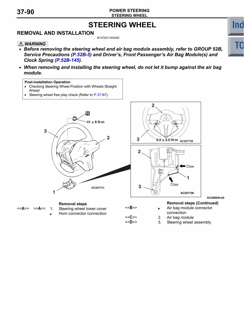
STEERING WHEELPOWER STEERING37-90
STEERING WHEELREMOVAL AND INSTALLATION
M1372011400365
WARNING• Before removing the steering wheel and air bag module assembly, refer to GROUP 52B,
Service Precautions (P.52B-5) and Drivers, Front Passengers Air Bag Module(s) and Clock Spring (P.52B-145).
•
Post-installation Operation• Checking Steering Wheel Position with Wheels Straight
Ahead• Steering wheel free play check (Refer to P.37-87).
AC207738
AC207739
AC207731
AC208946AB
41 ± 8 N·m
1
23
N
2
3
1
2
3
9.0 ± 2.0 N·m
Claw
Claw
Removal steps <<A>> >>A<< 1. Steering wheel lower cover
• Horn connector connection<<B>> • Air bag module connector
connection<<C>> 2. Air bag module<<D>> 3. Steering wheel assembly
When removing and installing the steering wheel, do not let it bump against the air bag module.
Removal steps (Continued)
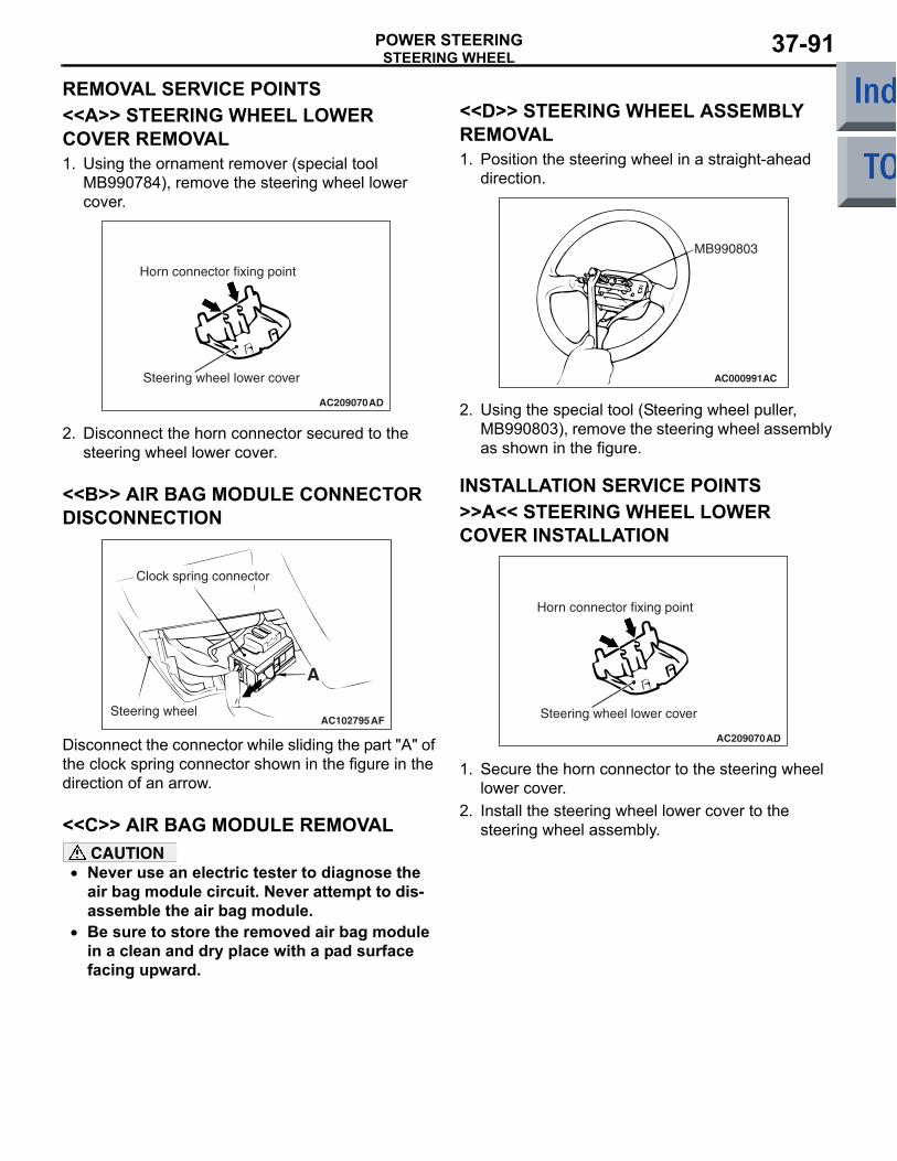
STEERING WHEELPOWER STEERING 37-91
REMOVAL SERVICE POINTS<<A>> STEERING WHEEL LOWER COVER REMOVAL1. Using the ornament remover (special tool
MB990784), remove the steering wheel lower cover.
AC209070
Steering wheel lower cover
Horn connector fixing point
AD
2. Disconnect the horn connector secured to the steering wheel lower cover.
<<B>> AIR BAG MODULE CONNECTOR DISCONNECTION
AC102795AF
A
Clock spring connector
Steering wheel
Disconnect the connector while sliding the part "A" of the clock spring connector shown in the figure in the direction of an arrow.
<<C>> AIR BAG MODULE REMOVALCAUTION
• Never use an electric tester to diagnose the air bag module circuit. Never attempt to dis-assemble the air bag module.
• Be sure to store the removed air bag module in a clean and dry place with a pad surface facing upward.
<<D>> STEERING WHEEL ASSEMBLY REMOVAL1. Position the steering wheel in a straight-ahead
direction.
AC000991
MB990803
AC
2. Using the special tool (Steering wheel puller, MB990803), remove the steering wheel assembly as shown in the figure.
INSTALLATION SERVICE POINTS>>A<< STEERING WHEEL LOWER COVER INSTALLATION
AC209070
Steering wheel lower cover
Horn connector fixing point
AD
1. Secure the horn connector to the steering wheel lower cover.
2. Install the steering wheel lower cover to the steering wheel assembly.
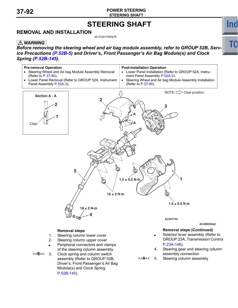
STEERING SHAFTPOWER STEERING37-92
STEERING SHAFTREMOVAL AND INSTALLATION
M1372011500276
WARNINGBefore removing the steering wheel and air bag module assembly, refer to GROUP 52B, Serv-ice Precautions (P.52B-5) and Drivers, Front Passengers Air Bag Module(s) and Clock Spring (P.52B-145).
Pre-removal Operation• Steering Wheel and Air bag Module Assembly Removal
(Refer to P.37-90).• Lower Panel Removal (Refer to GROUP 52A, Instrument
Panel Assembly P.52A-3).
Post-installation Operation• Lower Panel Installation (Refer to GROUP 52A, Instru-
ment Panel Assembly P.52A-3).• Steering Wheel and Air bag Module Assembly Installation
(Refer to P.37-90).
AC207733
AC208339AC
12 ± 2 N·m
18 ± 2 N·m
A
A
32
1
5
Section A - A
Claw
2
1.5 ± 0.5 N·m
1
1.5 ± 0.5 N·m
NOTE: Claw position
4
Removal steps 1. Steering column lower cover2. Steering column upper cover• Peripheral connectors and clamps
of the steering column assembly>>B<< 3. Clock spring and column switch
assembly (Refer to GROUP 52B, Drivers, Front Passengers Air Bag Module(s) and Clock Spring P.52B-145).
• Selector lever assembly (Refer to GROUP 23A, Transmission Control P.23A-146).
4. Steering gear and steering column assembly connection
>>A<< 5. Steering column assembly
Removal steps (Continued)
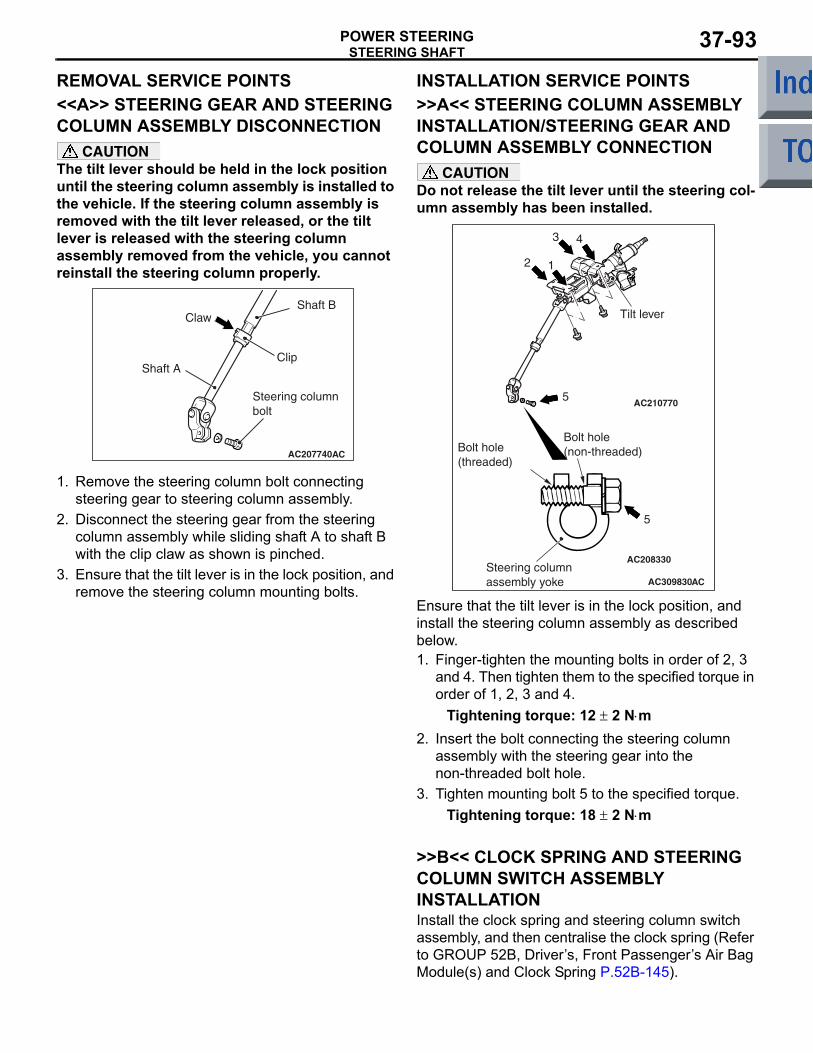
STEERING SHAFTPOWER STEERING 37-93
REMOVAL SERVICE POINTS<<A>> STEERING GEAR AND STEERING COLUMN ASSEMBLY DISCONNECTION
CAUTIONThe tilt lever should be held in the lock position until the steering column assembly is installed to the vehicle. If the steering column assembly is removed with the tilt lever released, or the tilt lever is released with the steering column assembly removed from the vehicle, you cannot reinstall the steering column properly.
AC207740AC
Claw
Clip
Shaft B
Shaft A
Steering column bolt
1. Remove the steering column bolt connecting steering gear to steering column assembly.
2. Disconnect the steering gear from the steering column assembly while sliding shaft A to shaft B with the clip claw as shown is pinched.
3. Ensure that the tilt lever is in the lock position, and remove the steering column mounting bolts.
INSTALLATION SERVICE POINTS>>A<< STEERING COLUMN ASSEMBLY INSTALLATION/STEERING GEAR AND COLUMN ASSEMBLY CONNECTION
CAUTIONDo not release the tilt lever until the steering col-umn assembly has been installed.
AC210770
AC208330
AC309830
Bolt hole (non-threaded)Bolt hole
(threaded)
Steering column assembly yoke
5
5
2 1
3 4
Tilt lever
AC
Ensure that the tilt lever is in the lock position, and install the steering column assembly as described below.1. Finger-tighten the mounting bolts in order of 2, 3
and 4. Then tighten them to the specified torque in order of 1, 2, 3 and 4.
Tightening torque: 12 ± 2 N⋅m2. Insert the bolt connecting the steering column
assembly with the steering gear into the non-threaded bolt hole.
3. Tighten mounting bolt 5 to the specified torque.Tightening torque: 18 ± 2 N⋅m
>>B<< CLOCK SPRING AND STEERING COLUMN SWITCH ASSEMBLY INSTALLATIONInstall the clock spring and steering column switch assembly, and then centralise the clock spring (Refer to GROUP 52B, Drivers, Front Passengers Air Bag Module(s) and Clock Spring P.52B-145).
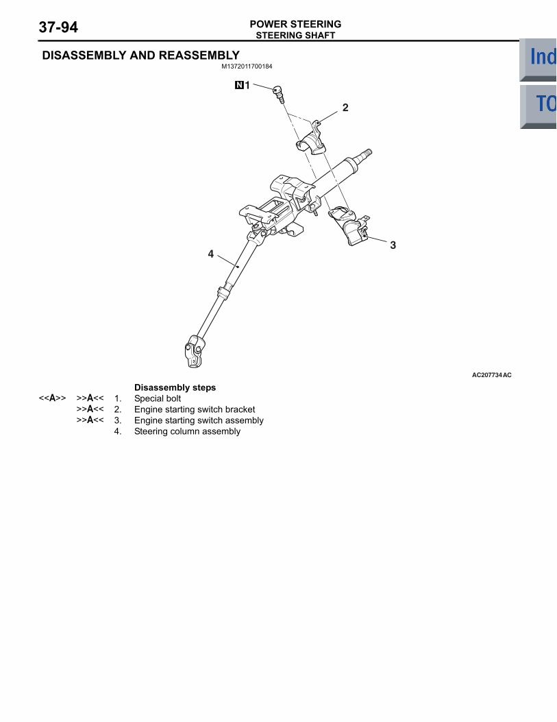
STEERING SHAFTPOWER STEERING37-94
DISASSEMBLY AND REASSEMBLYM1372011700184
AC207734AC
3
2
4
1
Disassembly steps <<A>> >>A<< 1. Special bolt
>>A<< 2. Engine starting switch bracket>>A<< 3. Engine starting switch assembly
4. Steering column assembly
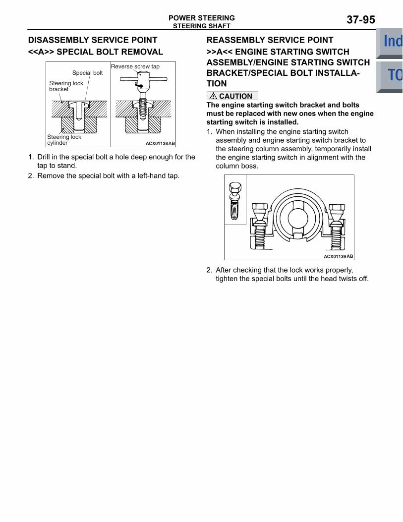
STEERING SHAFTPOWER STEERING 37-95
DISASSEMBLY SERVICE POINT<<A>> SPECIAL BOLT REMOVAL
ACX01138AB
Steering lock bracket
Reverse screw tapSpecial bolt
Steering lock cylinder
1. Drill in the special bolt a hole deep enough for the tap to stand.
2. Remove the special bolt with a left-hand tap.
REASSEMBLY SERVICE POINT>>A<< ENGINE STARTING SWITCH ASSEMBLY/ENGINE STARTING SWITCH BRACKET/SPECIAL BOLT INSTALLA-TION
CAUTIONThe engine starting switch bracket and bolts must be replaced with new ones when the engine starting switch is installed.1. When installing the engine starting switch
assembly and engine starting switch bracket to the steering column assembly, temporarily install the engine starting switch in alignment with the column boss.
ACX01139AB
2. After checking that the lock works properly, tighten the special bolts until the head twists off.
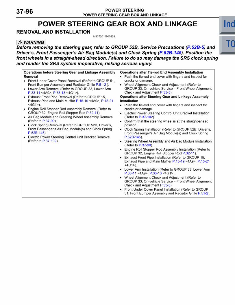
POWER STEERING GEAR BOX AND LINKAGEPOWER STEERING37-96
POWER STEERING GEAR BOX AND LINKAGEREMOVAL AND INSTALLATION
M1372010900828
WARNINGBefore removing the steering gear, refer to GROUP 52B, Service Precautions (P.52B-5) and Drivers, Front Passengers Air Bag Module(s) and Clock Spring (P.52B-145). Position the front wheels in a straight-ahead direction. Failure to do so may damage the SRS clock spring and render the SRS system inoperative, risking serious injury.
Operations before Steering Gear and Linkage Assembly Removal• Front Under Cover Panel Removal (Refer to GROUP 51,
Front Bumper Assembly and Radiator Grille P.51-2 ).• Lower Arm Removal (Refer to GROUP 33, Lower Arm
P.33-11 <4A9>, P.33-13 <4G1>).• Exhaust Front Pipe Removal (Refer to GROUP 15,
Exhaust Pipe and Main Muffler P.15-19 <4A9>, P.15-21 <4G1>).
• Engine Roll Stopper Rod Assembly Removal (Refer to GROUP 32, Engine Roll Stopper Rod P.32-11).
• Air Bag Module and Steering Wheel Assembly Removal (Refer to P.37-90).
• Clock Spring Removal (Refer to GROUP 52B, Drivers, Front Passengers Air Bag Module(s) and Clock Spring P.52B-145).
• Electric Power Steering Control Unit Bracket Removal (Refer to P.37-102).
Operations after Tie-rod End Assembly Installation• Push the tie-rod end cover with fingers and inspect for
cracks or damage.• Wheel Alignment Check and Adjustment (Refer to
GROUP 33, On-vehicle Service − Front Wheel Alignment Check and Adjustment P.33-5).
Operations after Steering Gear and Linkage Assembly Installation• Push the tie-rod end cover with fingers and inspect for
cracks or damage.• Electric Power Steering Control Unit Bracket Installation
(Refer to P.37-102).• Confirm that the steering wheel is at the straight-ahead
position.• Clock Spring Installation (Refer to GROUP 52B, Drivers,
Front Passengers Air Bag Module(s) and Clock Spring P.52B-145).
• Steering Wheel Assembly and Air Bag Module Installation (Refer to P.37-90).
• Engine Roll Stopper Rod Assembly Installation (Refer to GROUP 32, Engine Roll Stopper Rod P.32-11).
• Exhaust Front Pipe Installation (Refer to GROUP 15, Exhaust Pipe and Main Muffler P.15-19 <4A9>, P.15-21 <4G1>).
• Lower Arm Installation (Refer to GROUP 33, Lower Arm P.33-11 <4A9>, P.33-13 <4G1>).
• Wheel Alignment Check and Adjustment (Refer to GROUP 33, On-vehicle Service − Front Wheel Alignment Check and Adjustment P.33-5).
• Front Under Cover Panel Installation (Refer to GROUP 51, Front Bumper Assembly and Radiator Grille P.51-2).
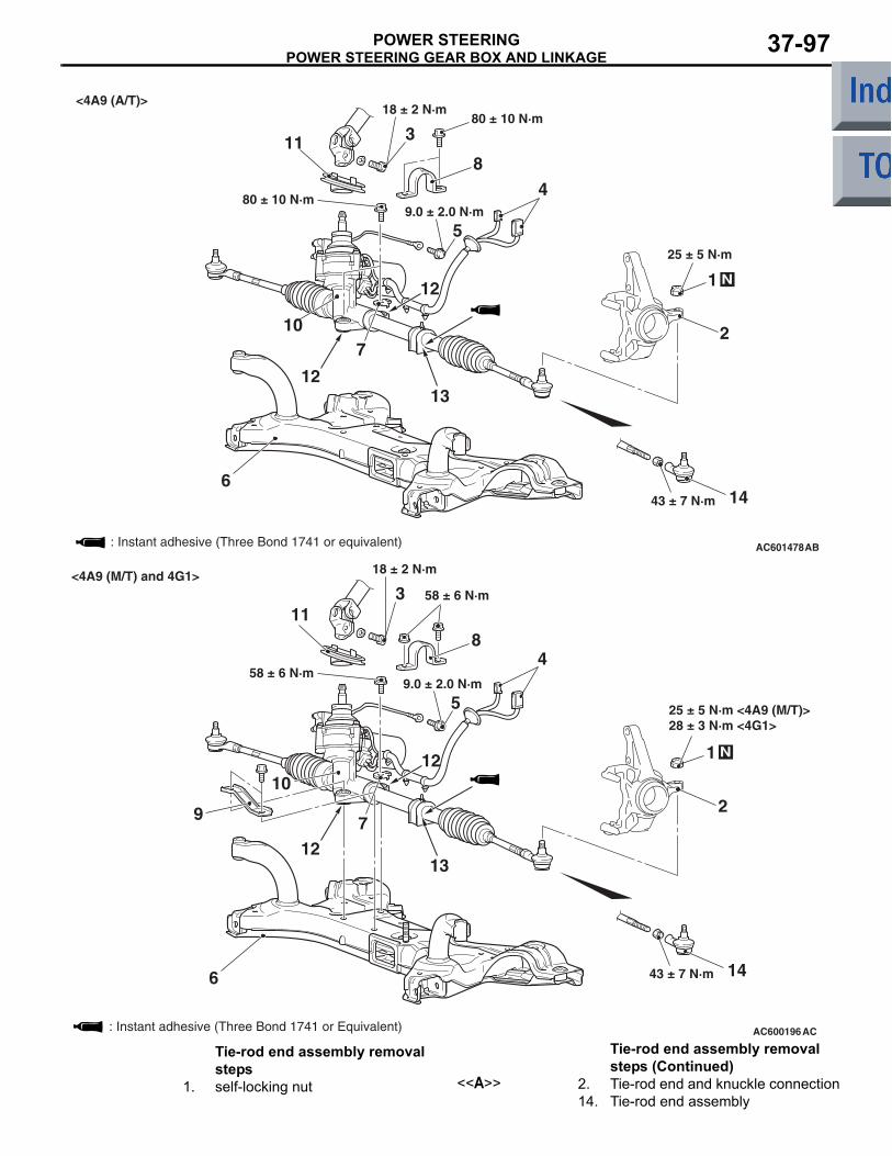
POWER STEERING GEAR BOX AND LINKAGEPOWER STEERING 37-97
AC601478
2
4
3118
6
5
12
25 ± 5 N·m
80 ± 10 N·m9.0 ± 2.0 N·m
18 ± 2 N·m
N
AB
7
80 ± 10 N·m
12
13
1443 ± 7 N·m
10
<4A9 (A/T)>
1
: Instant adhesive (Three Bond 1741 or equivalent)
AC600196
2
4
311
8
6
5
12
9.0 ± 2.0 N·m
18 ± 2 N·m
N
AC
7
58 ± 6 N·m
12
: Instant adhesive (Three Bond 1741 or Equivalent)
13
1443 ± 7 N·m
10
9
1
<4A9 (M/T) and 4G1>
58 ± 6 N·m
28 ± 3 N·m <4G1>25 ± 5 N·m <4A9 (M/T)>
Tie-rod end assembly removal steps
1. self-locking nut <<A>> 2. Tie-rod end and knuckle connection14. Tie-rod end assembly
Tie-rod end assembly removal steps (Continued)
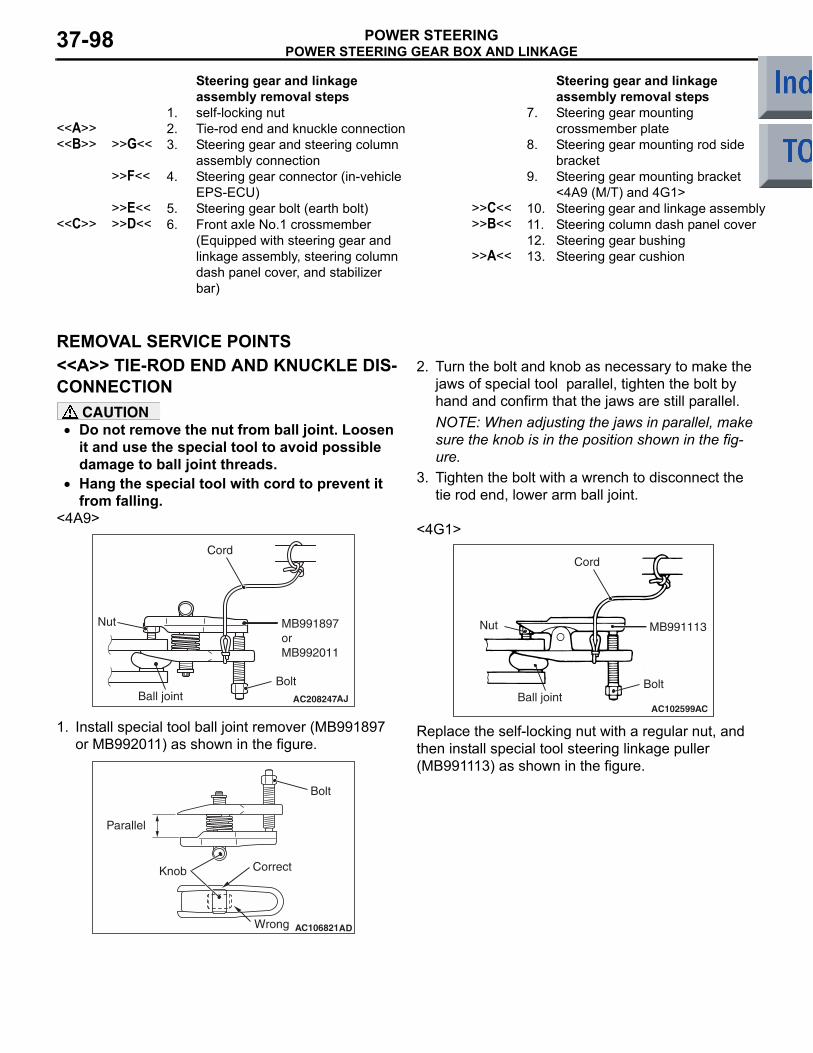
POWER STEERING GEAR BOX AND LINKAGEPOWER STEERING37-98
Steering gear and linkage assembly removal steps
1. self-locking nut<<A>> 2. Tie-rod end and knuckle connection<<B>> >>G<< 3. Steering gear and steering column
assembly connection>>F<< 4. Steering gear connector (in-vehicle
EPS-ECU)>>E<< 5. Steering gear bolt (earth bolt)
<<C>> >>D<< 6. Front axle No.1 crossmember (Equipped with steering gear and linkage assembly, steering column dash panel cover, and stabilizer bar)
7. Steering gear mounting crossmember plate
8. Steering gear mounting rod side bracket
9. Steering gear mounting bracket <4A9 (M/T) and 4G1>
>>C<< 10. Steering gear and linkage assembly>>B<< 11. Steering column dash panel cover
12. Steering gear bushing>>A<< 13. Steering gear cushion
REMOVAL SERVICE POINTS<<A>> TIE-ROD END AND KNUCKLE DIS-CONNECTION
CAUTION• Do not remove the nut from ball joint. Loosen
it and use the special tool to avoid possible damage to ball joint threads.
• Hang the special tool with cord to prevent it from falling.
<4A9>
AC208247AJ
Cord
Bolt
MB991897orMB992011
Nut
Ball joint
1. Install special tool ball joint remover (MB991897 or MB992011) as shown in the figure.
AC106821
Knob
Parallel
Bolt
Correct
Wrong AD
2. Turn the bolt and knob as necessary to make the jaws of special tool parallel, tighten the bolt by hand and confirm that the jaws are still parallel.NOTE: When adjusting the jaws in parallel, make sure the knob is in the position shown in the fig-ure.
3. Tighten the bolt with a wrench to disconnect the tie rod end, lower arm ball joint.
<4G1>
AC102599AC
Cord
Bolt
MB991113Nut
Ball joint
Replace the self-locking nut with a regular nut, and then install special tool steering linkage puller (MB991113) as shown in the figure.
Steering gear and linkage assembly removal steps
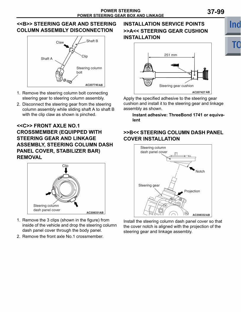
POWER STEERING GEAR BOX AND LINKAGEPOWER STEERING 37-99
<<B>> STEERING GEAR AND STEERING COLUMN ASSEMBLY DISCONNECTION
AC207740AB
Clip
Steering column bolt
Claw Shaft B
Shaft A
1. Remove the steering column bolt connecting steering gear to steering column assembly.
2. Disconnect the steering gear from the steering column assembly while sliding shaft A to shaft B with the clip claw as shown is pinched.
<<C>> FRONT AXLE NO.1 CROSSMEMBER (EQUIPPED WITH STEERING GEAR AND LINKAGE ASSEMBLY, STEERING COLUMN DASH PANEL COVER, STABILIZER BAR) REMOVAL
AC208331AB
Clip
Steering column dash panel cover
1. Remove the 3 clips (shown in the figure) from inside of the vehicle and drop the steering column dash panel cover through the body panel.
2. Remove the front axle No.1 crossmember.
INSTALLATION SERVICE POINTS>>A<< STEERING GEAR CUSHION INSTALLATION
AC207427 AB
Steering gear cushion
251 mm
Apply the specified adhesive to the steering gear cushion and install it to the steering gear and linkage assembly as shown.
Instant adhesive: ThreeBond 1741 or equiva-lent
>>B<< STEERING COLUMN DASH PANEL COVER INSTALLATION
AC208332AB
Steering gear
Steering column dash panel cover
Notch
Projection
Install the steering column dash panel cover so that the cover notch is aligned with the projection of the steering gear and linkage assembly.
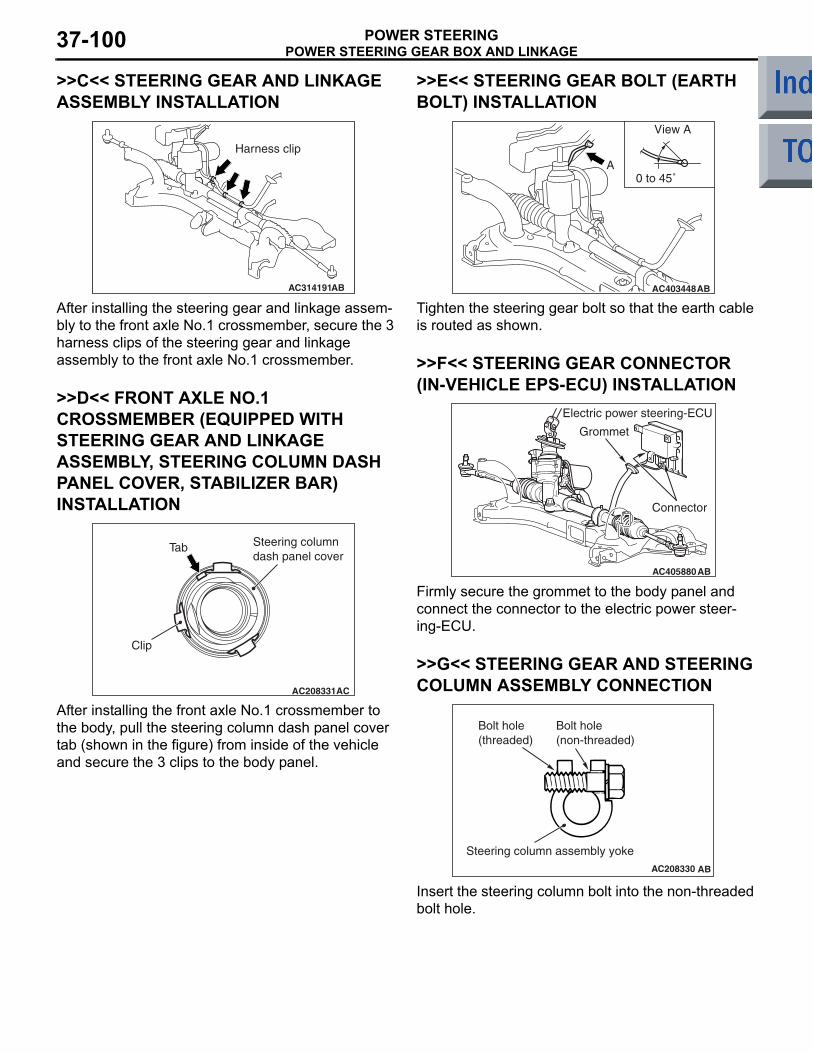
POWER STEERING GEAR BOX AND LINKAGEPOWER STEERING37-100
>>C<< STEERING GEAR AND LINKAGE ASSEMBLY INSTALLATION
AC314191AB
Harness clip
After installing the steering gear and linkage assem-bly to the front axle No.1 crossmember, secure the 3 harness clips of the steering gear and linkage assembly to the front axle No.1 crossmember.
>>D<< FRONT AXLE NO.1 CROSSMEMBER (EQUIPPED WITH STEERING GEAR AND LINKAGE ASSEMBLY, STEERING COLUMN DASH PANEL COVER, STABILIZER BAR) INSTALLATION
AC208331AC
Clip
Steering column dash panel cover
Tab
After installing the front axle No.1 crossmember to the body, pull the steering column dash panel cover tab (shown in the figure) from inside of the vehicle and secure the 3 clips to the body panel.
>>E<< STEERING GEAR BOLT (EARTH BOLT) INSTALLATION
AC403448AB
View A
A0 to 45˚
Tighten the steering gear bolt so that the earth cable is routed as shown.
>>F<< STEERING GEAR CONNECTOR (IN-VEHICLE EPS-ECU) INSTALLATION
AC405880AB
Electric power steering-ECU
Connector
Grommet
Firmly secure the grommet to the body panel and connect the connector to the electric power steer-ing-ECU.
>>G<< STEERING GEAR AND STEERING COLUMN ASSEMBLY CONNECTION
AC208330 AB
Steering column assembly yoke
Bolt hole (threaded)
Bolt hole (non-threaded)
Insert the steering column bolt into the non-threaded bolt hole.
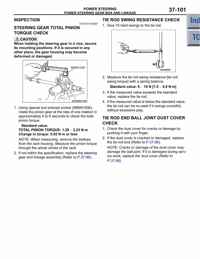
POWER STEERING GEAR BOX AND LINKAGEPOWER STEERING 37-101
INSPECTIONM1372011000367
STEERING GEAR TOTAL PINION TORQUE CHECK
CAUTIONWhen holding the steering gear in a vice, secure its mounting positions. If it is secured in any other place, the gear housing may become deformed or damaged.
AC208337AB
MB991006
1. Using special tool preload socket (MB991006), rotate the pinion gear at the rate of one rotation in approximately 4 to 6 seconds to check the total pinion torque.
Standard value:TOTAL PINION TORQUE: 1.29 − 2.23 N⋅mChange in torque: 0.92 N⋅m or lessNOTE: When measuring, remove the bellows from the rack housing. Measure the pinion torque through the whole stroke of the rack.
2. If not within the specification, replace the steering gear and linkage assembly (Refer to P.37-96).
TIE ROD SWING RESISTANCE CHECK1. Give 10 hard swings to the tie rod.
AC000997
2. Measure the tie rod swing resistance [tie rod swing torque] with a spring balance.
Standard value: 6 − 19 N [1.5 − 4.9 N⋅m]3. If the measured value exceeds the standard
value, replace the tie rod.4. If the measured value is below the standard value,
the tie rod can be re-used if it swings smoothly without excessive play.
TIE ROD END BALL JOINT DUST COVER CHECK1. Check the dust cover for cracks or damage by
pushing it with your finger.2. If the dust cover is cracked or damaged, replace
the tie rod end (Refer to P.37-96).NOTE: Cracks or damage of the dust cover may damage the ball joint. If it is damaged during serv-ice work, replace the dust cover (Refer to P.37-96).
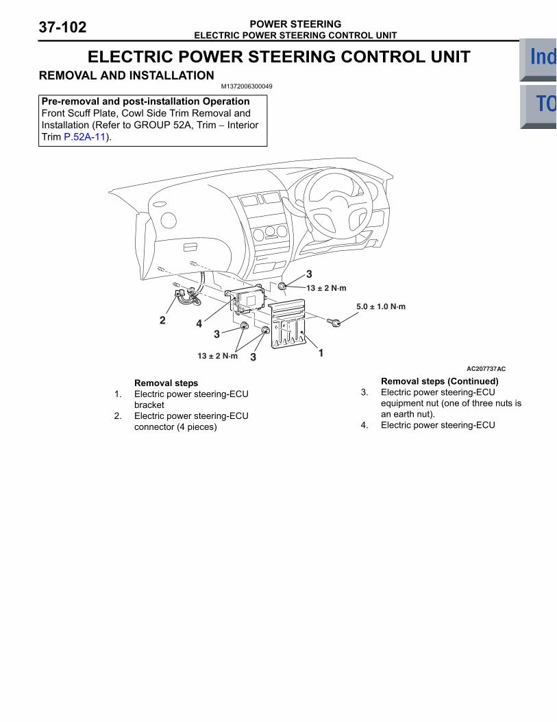
ELECTRIC POWER STEERING CONTROL UNITPOWER STEERING37-102
ELECTRIC POWER STEERING CONTROL UNITREMOVAL AND INSTALLATION
M1372006300049
Pre-removal and post-installation OperationFront Scuff Plate, Cowl Side Trim Removal and Installation (Refer to GROUP 52A, Trim − Interior Trim P.52A-11).
AC207737AC
1
13 ± 2 N·m
2
3
4
5.0 ± 1.0 N·m
3
13 ± 2 N·m 3
Removal steps 1. Electric power steering-ECU
bracket2. Electric power steering-ECU
connector (4 pieces)
3. Electric power steering-ECU equipment nut (one of three nuts is an earth nut).
4. Electric power steering-ECU
Removal steps (Continued)