Embed Size (px)
Citation preview
37-1
GROUP 37
ELECTRIC POWER STEERING (EPS)
CONTENTS
SERVICE SPECIFICATIONS. . . . . . . 37-3
LUBRICANT. . . . . . . . . . . . . . . . . . . . 37-3
SEALANT. . . . . . . . . . . . . . . . . . . . . . 37-3
SPECIAL TOOLS. . . . . . . . . . . . . . . . 37-4
TROUBLESHOOTING . . . . . . . . . . . . 37-6DIAGNOSIS TROUBLESHOOTING FLOW 37-6DIAGNOSTIC FUNCTION . . . . . . . . . . . . . 37-7CHECK OF ELECTRIC POWER STEERING WARNING LAMP . . . . . . . . . . . . . . . . . . . . 37-8DIAGNOSIS CODE CHART . . . . . . . . . . . . 37-8DIAGNOSIS CODE PROCEDURES . . . . . 37-9Code No.C1510 Torque sensor main Code No.C1511 Torque sensor sub . . . . . . 37-9Code No.C1512 Torque sensor main/sub voltage . . . . . . . . . . . . . . . . . . . . . . . . . . . . . . . . . . . . . . 37-11Code No.C1513 Torque sensor power supply . . . . . . . . . . . . . . . . . . . . . . . . . . . . . . . . . . . . . . 37-12Code No.C1514 Torque sensor power supply too low . . . . . . . . . . . . . . . . . . . . . . . . . . . . . . . . . . . . . . 37-14Code No.C1521 Motor turning angle (output) Code No.C1522 Motor turning angle range 37-15Code No.C1530 Motor FET driver Code No.C1531 Motor current too low Code No.C1532 Motor output current too large Code No.C1533 Motor terminal initial voltage Code No.C1534 Motor terminal monitor voltage Code No.C1535 Motor output current Code No.C1536 Motor terminal voltage too high . . . . . . . . . . . . . . . . . . . . . . . . . . . . . . . . . . . . . . 37-16Code No.C1540 Power supply voltage too high . . . . . . . . . . . . . . . . . . . . . . . . . . . . . . . . . . . . . . 37-18Code No.C1541 Power supply voltage too low
. . . . . . . . . . . . . . . . . . . . . . . . . . . . . . . . . . . . . . 37-19Code No.C1550 ECU internal error . . . . . . . 37-21Code No.C1561 Engine revolution data (CAN) . . . . . . . . . . . . . . . . . . . . . . . . . . . . . . . . . . . . . . 37-21Code No.C1564 Vehicle speed data invalid 37-22Code No.C1565 Engine revolution data invalid . . . . . . . . . . . . . . . . . . . . . . . . . . . . . . . . . . . . . . 37-23Code No.C1566 Invalid data received from AWC . . . . . . . . . . . . . . . . . . . . . . . . . . . . . . . . . . . . . . 37-24Code No. C1657 Implausible coding data . . 37-25Code No. U0100 Engine CAN timeout Code No. U0114 4WD CAN timeout Code No. U0141 ETACS CAN timeout . . . . 37-26Code No. U1073 Bus-off . . . . . . . . . . . . . . . 37-27Code No. U1190 No receive fault detect signal . . . . . . . . . . . . . . . . . . . . . . . . . . . . . . . . . . . . . . 37-27Code No. U1195 Coding not completed Code No. U1197 Coding data unavailable . 37-28TROUBLE SYMPTOM CHART . . . . . . . . . . 37-29SYMPTOM PROCEDURES . . . . . . . . . . . . 37-29Inspection Procedure 1: M.U.T.-III cannot communicate with electric power steering system <ECU power supply circuit system check>. . . . . . . . . . . . . . . . . . 37-29Inspection Procedure 2: Electric power steering system warning display illuminates but diagnosis code is not stored. . . . . . . . . . . . . . . . . . . . . . . . . . . . . . 37-30Inspection Procedure 3: The steering has become heavy, but electric power steering warning display does not illuminate. (Power supply voltage assist fall) . . . . . . . . . . . . . . . . . . . . . . . . . . . . . . . . . . . . . . 37-31DATA LIST REFERENCE TABLE. . . . . . . . 37-32ACTUATOR TEST REFERENCE TABLE . . 37-36CHECK AT ELECTRIC POWER STEERING-ECU . . . . . . . . . . . . . . . . . . . . . . . . . . . . . . . . . . . . . . 37-36
ON-VEHICLE SERVICE . . . . . . . . . . . 37-37
37-2
STEERING WHEEL PLAY CHECK . . . . . . 37-37STEERING ANGLE CHECK. . . . . . . . . . . . 37-38BALL JOINT DUST COVER CHECK . . . . . 37-38BALL JOINT ROTATION TORQUE CHECK . . . . . . . . . . . . . . . . . . . . . . . . . . . . . . . . . . . . . . 37-38STATIONARY STEERING FORCE CHECK . . . . . . . . . . . . . . . . . . . . . . . . . . . . . . . . . . . . . . 37-39RETURN CHECK OF STEERING WHEEL 37-39INSPECTION OF STEERING COLUMN SHAFT ASSEMBLY IMPACT ABSORBING MECHANISM . . . . . . . . . . . . . . . . . . . . . . . . . . . . . . . . . . . . . . 37-40
STEERING WHEEL . . . . . . . . . . . . . . 37-41REMOVAL AND INSTALLATION . . . . . . . . 37-41
STEERING COLUMN SHAFT ASSEMBLY
. . . . . . . . . . . . . . . . . . . . . . . . . . . . . . . . . 37-43REMOVAL AND INSTALLATION . . . . . . . . 37-43INSPECTION. . . . . . . . . . . . . . . . . . . . . . . . 37-45DISASSEMBLY AND REASSEMBLY . . . . . 37-46INSPECTION. . . . . . . . . . . . . . . . . . . . . . . . 37-47
POWER STEERING GEAR BOX AND LINKAGE . . . . . . . . . . . . . . . . . . . . . . 37-48
REMOVAL AND INSTALLATION . . . . . . . . 37-48INSPECTION. . . . . . . . . . . . . . . . . . . . . . . . 37-48DISASSEMBLY AND REASSEMBLY . . . . . 37-48
ELECTRIC POWER STEERING CONTROL UNIT (EPS-ECU). . . . . . . . . . . . . . . . . 37-51
REMOVAL AND INSTALLATION . . . . . . . . 37-51
SERVICE SPECIFICATIONSELECTRIC POWER STEERING (EPS) 37-3
SERVICE SPECIFICATIONSM1372000302252
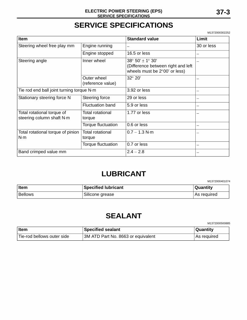
Item Standard value LimitSteering wheel free play mm Engine running − 30 or less
Engine stopped 16.5 or less −
Steering angle Inner wheel 38° 50' ± 1° 30'(Difference between right and left wheels must be 2°00’ or less)
−
Outer wheel (reference value)
32° 20' −
Tie rod end ball joint turning torque N⋅m 3.92 or less −
Stationary steering force N Steering force 29 or less −
Fluctuation band 5.9 or less −
Total rotational torque of steering column shaft N⋅m
Total rotational torque
1.77 or less −
Torque fluctuation 0.6 or less −
Total rotational torque of pinion N⋅m
Total rotational torque
0.7 − 1.3 N⋅m −
Torque fluctuation 0.7 or less −
Band crimped value mm 2.4 − 2.8 −
LUBRICANTM1372000401074
Item Specified lubricant QuantityBellows Silicone grease As required
SEALANTM1372000500885
Item Specified sealant QuantityTie-rod bellows outer side 3M ATD Part No. 8663 or equivalent As required
SPECIAL TOOLSELECTRIC POWER STEERING (EPS)37-4
SPECIAL TOOLSM1372000601852
Tool Number Name Use
ACB05421
MB992745
MB992746
MB992744
MB992747
MB992748
a
b
c
d
e
DO NOT USE
AB
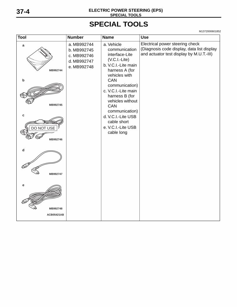
a. MB992744b. MB992745c. MB992746d. MB992747e. MB992748
a. Vehicle communication interface-Lite (V.C.I.-Lite)
b. V.C.I.-Lite main harness A (for vehicles with CAN communication)
c. V.C.I.-Lite main harness B (for vehicles without CAN communication)
d. V.C.I.-Lite USB cable short
e. V.C.I.-Lite USB cable long
Electrical power steering check (Diagnosis code display, data list display and actuator test display by M.U.T.-III)
SPECIAL TOOLSELECTRIC POWER STEERING (EPS) 37-5
MB991910
MB991826
MB991955
MB991911
MB991824
MB991827
MB991825
a
b
c
d
e
f
DO NOT USE
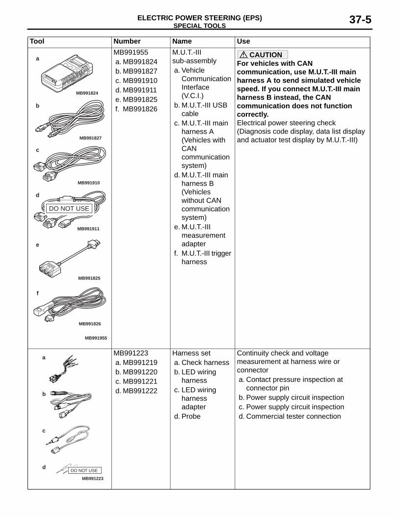
MB991955a. MB991824b. MB991827c. MB991910d. MB991911e. MB991825f. MB991826
M.U.T.-III sub-assemblya. Vehicle
Communication Interface (V.C.I.)
b. M.U.T.-III USB cable
c. M.U.T.-III main harness A (Vehicles with CAN communication system)
d. M.U.T.-III main harness B (Vehicles without CAN communication system)
e. M.U.T.-III measurement adapter
f. M.U.T.-III trigger harness
CAUTIONFor vehicles with CAN communication, use M.U.T.-III main harness A to send simulated vehicle speed. If you connect M.U.T.-III main harness B instead, the CAN communication does not function correctly.Electrical power steering check (Diagnosis code display, data list display and actuator test display by M.U.T.-III)
MB991223
a
d
c
b
DO NOT USE
MB991223a. MB991219b. MB991220c. MB991221d. MB991222
Harness seta. Check harnessb. LED wiring
harnessc. LED wiring
harness adapter
d. Probe
Continuity check and voltage measurement at harness wire or connectora. Contact pressure inspection at
connector pinb. Power supply circuit inspectionc. Power supply circuit inspectiond. Commercial tester connection
Tool Number Name Use
TROUBLESHOOTINGELECTRIC POWER STEERING (EPS)37-6
MB992006
TROUBLESHOOTINGDIAGNOSIS TROUBLESHOOTING FLOW
M1372007300309Refer to GROUP 00 − Contents of Troubleshooting .
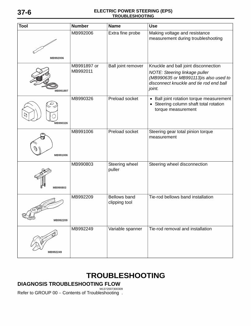
MB992006 Extra fine probe Making voltage and resistance measurement during troubleshooting
MB991897
MB991897 or MB992011
Ball joint remover Knuckle and ball joint disconnectionNOTE: Steering linkage puller (MB990635 or MB991113)is also used to disconnect knuckle and tie rod end ball joint.
MB990326
MB990326 Preload socket • Ball joint rotation torque measurement• Steering column shaft total rotation
torque measurement
MB991006
MB991006 Preload socket Steering gear total pinion torque measurement
MB990803
MB990803 Steering wheel puller
Steering wheel disconnection
MB992209
MB992209 Bellows band clipping tool
Tie-rod bellows band installation
MB992249
MB992249 Variable spanner Tie-rod removal and installation
Tool Number Name Use
TROUBLESHOOTINGELECTRIC POWER STEERING (EPS) 37-7
DIAGNOSTIC FUNCTIONM1372007400191
HOW TO READ DIAGNOSIS CODEConnect the M.U.T.-III to the 16-pin diagnosis con-nector, and read a diagnosis code (Refer to GROUP 00 − How to Use Troubleshooting/Inspection Service Points − Diagnosis Function ).
HOW TO ERASE DIAGNOSIS CODEConnect the M.U.T.-III to the 16-pin diagnosis con-nector, and erase a diagnosis code (Refer to GROUP 00 − How to Use Troubleshooting/Inspec-tion Service Points − Diagnosis Function ).
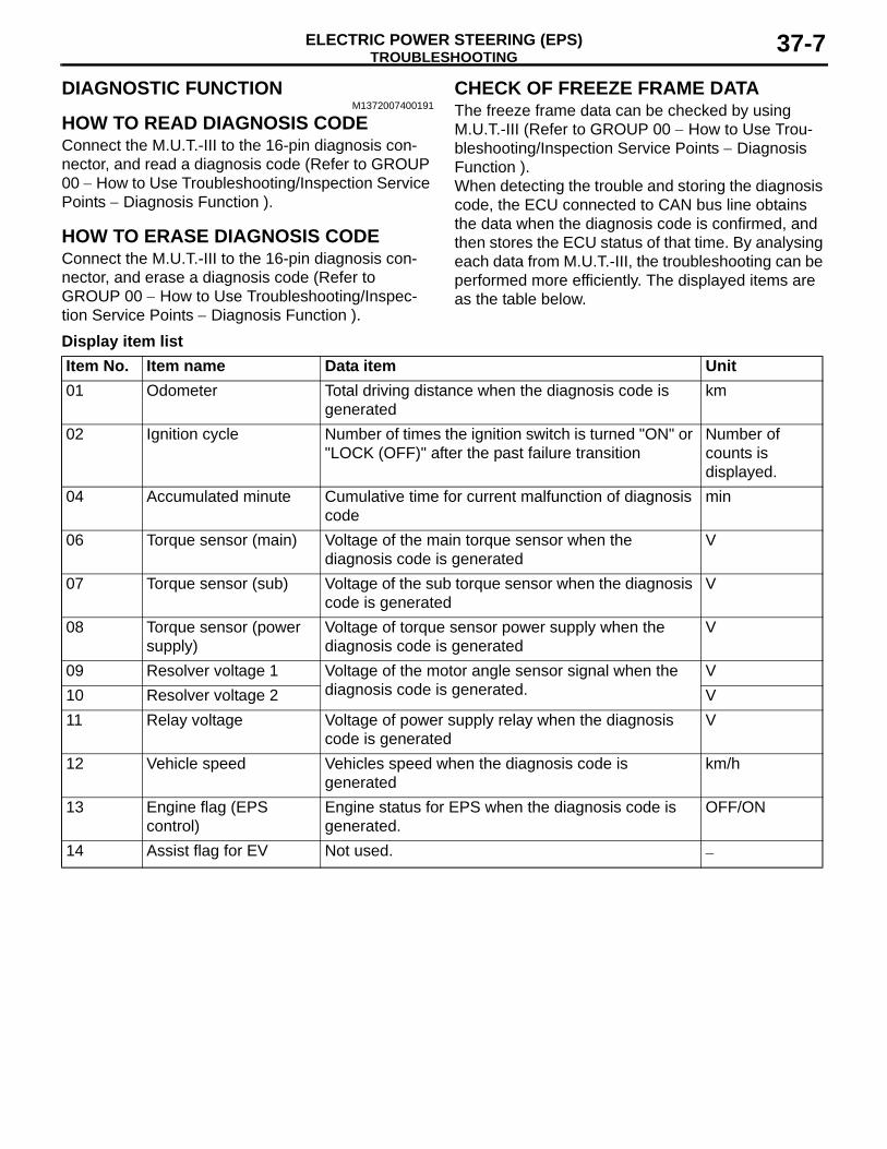
CHECK OF FREEZE FRAME DATAThe freeze frame data can be checked by using M.U.T.-III (Refer to GROUP 00 − How to Use Trou-bleshooting/Inspection Service Points − Diagnosis Function ).When detecting the trouble and storing the diagnosis code, the ECU connected to CAN bus line obtains the data when the diagnosis code is confirmed, and then stores the ECU status of that time. By analysing each data from M.U.T.-III, the troubleshooting can be performed more efficiently. The displayed items are as the table below.
Display item listItem No. Item name Data item Unit01 Odometer Total driving distance when the diagnosis code is
generatedkm
02 Ignition cycle Number of times the ignition switch is turned "ON" or "LOCK (OFF)" after the past failure transition
Number of counts is displayed.
04 Accumulated minute Cumulative time for current malfunction of diagnosis code
min
06 Torque sensor (main) Voltage of the main torque sensor when the diagnosis code is generated
V
07 Torque sensor (sub) Voltage of the sub torque sensor when the diagnosis code is generated
V
08 Torque sensor (power supply)
Voltage of torque sensor power supply when the diagnosis code is generated
V
09 Resolver voltage 1 Voltage of the motor angle sensor signal when the diagnosis code is generated.
V10 Resolver voltage 2 V11 Relay voltage Voltage of power supply relay when the diagnosis
code is generatedV
12 Vehicle speed Vehicles speed when the diagnosis code is generated
km/h
13 Engine flag (EPS control)
Engine status for EPS when the diagnosis code is generated.
OFF/ON
14 Assist flag for EV Not used. −
TROUBLESHOOTINGELECTRIC POWER STEERING (EPS)37-8
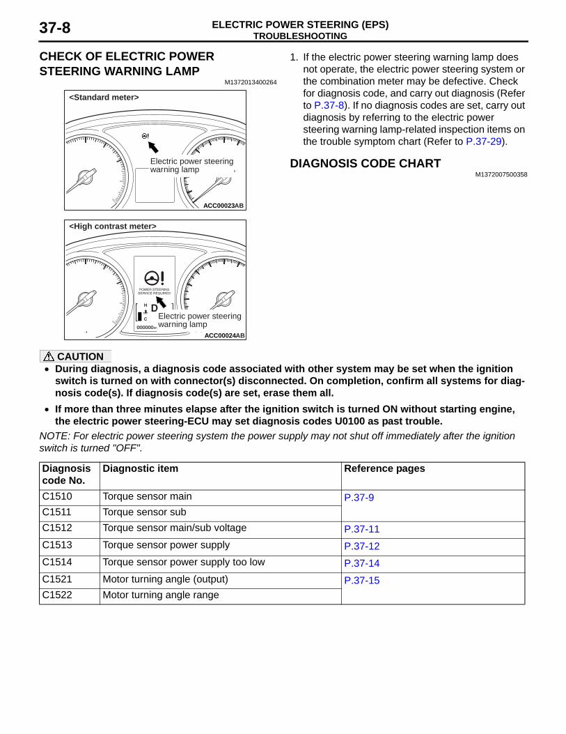
CHECK OF ELECTRIC POWER STEERING WARNING LAMP
M1372013400264
ACC00023AB
Electric power steeringwarning lamp
<Standard meter>
ACC00024AB
Electric power steeringwarning lamp
<High contrast meter>
1. If the electric power steering warning lamp does not operate, the electric power steering system or the combination meter may be defective. Check for diagnosis code, and carry out diagnosis (Refer to P.37-8). If no diagnosis codes are set, carry out diagnosis by referring to the electric power steering warning lamp-related inspection items on the trouble symptom chart (Refer to P.37-29).
DIAGNOSIS CODE CHARTM1372007500358
CAUTION• During diagnosis, a diagnosis code associated with other system may be set when the ignition
switch is turned on with connector(s) disconnected. On completion, confirm all systems for diag-nosis code(s). If diagnosis code(s) are set, erase them all.
• If more than three minutes elapse after the ignition switch is turned ON without starting engine, the electric power steering-ECU may set diagnosis codes U0100 as past trouble.
NOTE: For electric power steering system the power supply may not shut off immediately after the ignition switch is turned "OFF".
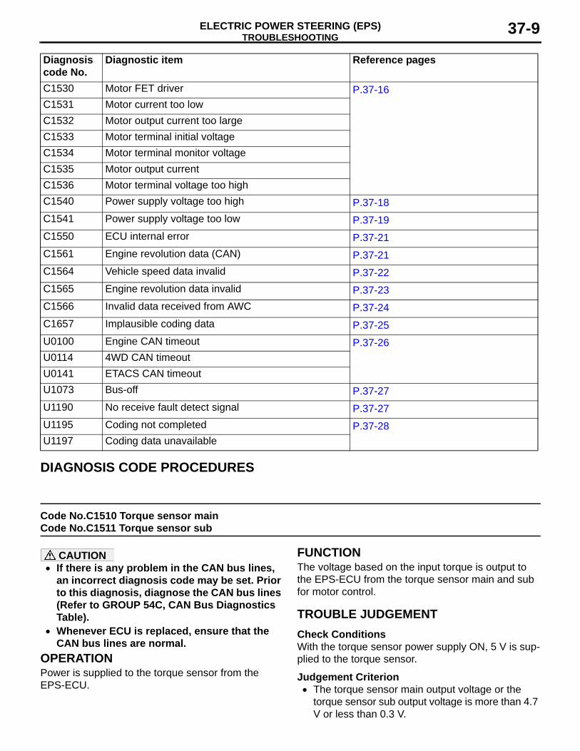
Diagnosis code No.
Diagnostic item Reference pages
C1510 Torque sensor main P.37-9C1511 Torque sensor subC1512 Torque sensor main/sub voltage P.37-11C1513 Torque sensor power supply P.37-12C1514 Torque sensor power supply too low P.37-14C1521 Motor turning angle (output) P.37-15C1522 Motor turning angle range
TROUBLESHOOTINGELECTRIC POWER STEERING (EPS) 37-9
DIAGNOSIS CODE PROCEDURES
Code No.C1510 Torque sensor main Code No.C1511 Torque sensor sub
CAUTION• If there is any problem in the CAN bus lines,
an incorrect diagnosis code may be set. Prior to this diagnosis, diagnose the CAN bus lines (Refer to GROUP 54C, CAN Bus Diagnostics Table).
• Whenever ECU is replaced, ensure that the CAN bus lines are normal.
OPERATIONPower is supplied to the torque sensor from the EPS-ECU.
FUNCTIONThe voltage based on the input torque is output to the EPS-ECU from the torque sensor main and sub for motor control.
TROUBLE JUDGEMENTCheck ConditionsWith the torque sensor power supply ON, 5 V is sup-plied to the torque sensor.
Judgement Criterion• The torque sensor main output voltage or the
torque sensor sub output voltage is more than 4.7 V or less than 0.3 V.
C1530 Motor FET driver P.37-16C1531 Motor current too lowC1532 Motor output current too largeC1533 Motor terminal initial voltageC1534 Motor terminal monitor voltageC1535 Motor output currentC1536 Motor terminal voltage too highC1540 Power supply voltage too high P.37-18C1541 Power supply voltage too low P.37-19C1550 ECU internal error P.37-21C1561 Engine revolution data (CAN) P.37-21C1564 Vehicle speed data invalid P.37-22C1565 Engine revolution data invalid P.37-23C1566 Invalid data received from AWC P.37-24C1657 Implausible coding data P.37-25U0100 Engine CAN timeout P.37-26U0114 4WD CAN timeoutU0141 ETACS CAN timeoutU1073 Bus-off P.37-27U1190 No receive fault detect signal P.37-27U1195 Coding not completed P.37-28U1197 Coding data unavailable
Diagnosis code No.
Diagnostic item Reference pages
TROUBLESHOOTINGELECTRIC POWER STEERING (EPS)37-10
• The torque sensor main output voltage or the torque sensor sub output voltage does not meet a predetermined voltage stored in the microcom-puter, and the microcomputer determines that there is a problem in the torque sensor main sys-tem or the torque sensor sub system.
Fail Safe, Back Up FunctionThe EPS-ECU stops the motor control and illumi-nates the electric power steering warning display, then sets the diagnosis code No. C1510 and C1511.
PROBABLE CAUSES• Malfunction of CAN bus line• Defective torque sensor of the steering column
shaft assembly• Defective harness wire(s) or connector(s)
• Short or open circuit between the EPS-ECU and the torque sensor or loose connector contact
• Malfunction of the EPS-ECU
DIAGNOSIS PROCEDURE
STEP 1. M.U.T.-III CAN bus diagnosticsUse M.U.T.-III to diagnose the CAN bus lines.
Q: Is the check result normal?YES : Go to Step 3.NO : Repair the CAN bus lines (Refer to GROUP
54C − CAN Bus Diagnostics Table ). On completion, go to Step 2.
STEP 2. Diagnosis code recheck after resetting CAN bus lines(1) Erase the diagnosis code.(2) Turn the ignition switch from the "LOCK" (OFF)
position to the "ON" position.(3) Check if the diagnosis code is set.
Q: Is the diagnosis codes C1510 or C1511 set?YES : Go to Step 3.NO : This diagnosis is complete.
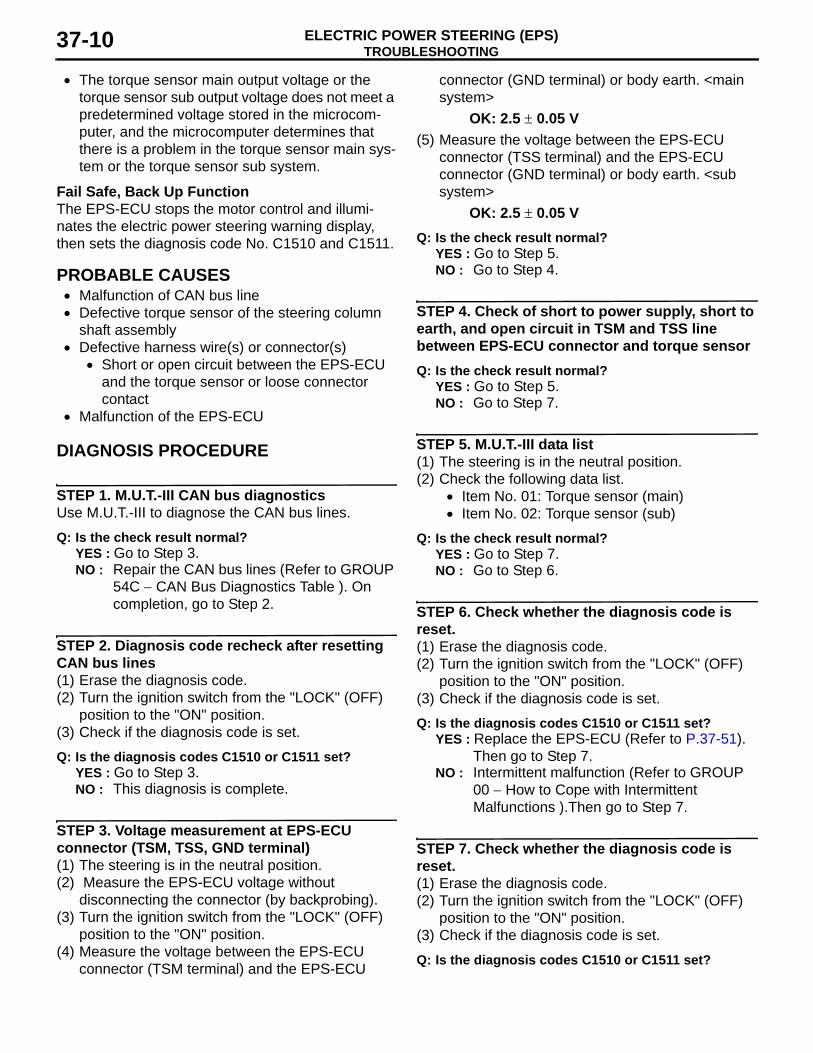
STEP 3. Voltage measurement at EPS-ECU connector (TSM, TSS, GND terminal)(1) The steering is in the neutral position.(2) Measure the EPS-ECU voltage without
disconnecting the connector (by backprobing).(3) Turn the ignition switch from the "LOCK" (OFF)
position to the "ON" position.(4) Measure the voltage between the EPS-ECU
connector (TSM terminal) and the EPS-ECU
connector (GND terminal) or body earth. <main system>
OK: 2.5 ± 0.05 V(5) Measure the voltage between the EPS-ECU
connector (TSS terminal) and the EPS-ECU connector (GND terminal) or body earth. <sub system>
OK: 2.5 ± 0.05 VQ: Is the check result normal?
YES : Go to Step 5.NO : Go to Step 4.
STEP 4. Check of short to power supply, short to earth, and open circuit in TSM and TSS line between EPS-ECU connector and torque sensorQ: Is the check result normal?
YES : Go to Step 5.NO : Go to Step 7.
STEP 5. M.U.T.-III data list(1) The steering is in the neutral position.(2) Check the following data list.
• Item No. 01: Torque sensor (main)• Item No. 02: Torque sensor (sub)
Q: Is the check result normal?YES : Go to Step 7.NO : Go to Step 6.
STEP 6. Check whether the diagnosis code is reset.(1) Erase the diagnosis code.(2) Turn the ignition switch from the "LOCK" (OFF)
position to the "ON" position.(3) Check if the diagnosis code is set.
Q: Is the diagnosis codes C1510 or C1511 set?YES : Replace the EPS-ECU (Refer to P.37-51).
Then go to Step 7.NO : Intermittent malfunction (Refer to GROUP
00 − How to Cope with Intermittent Malfunctions ).Then go to Step 7.
STEP 7. Check whether the diagnosis code is reset.(1) Erase the diagnosis code.(2) Turn the ignition switch from the "LOCK" (OFF)
position to the "ON" position.(3) Check if the diagnosis code is set.
Q: Is the diagnosis codes C1510 or C1511 set?
TROUBLESHOOTINGELECTRIC POWER STEERING (EPS) 37-11
YES : Replace the steering column shaft assembly (Refer to P.37-43). Then go to Step 8.
NO : Intermittent malfunction (Refer to GROUP 00 − How to Cope with Intermittent Malfunctions ).
STEP 8. Check whether the diagnosis code is reset.(1) Erase the diagnosis code.(2) Turn the ignition switch from the "LOCK" (OFF)
position to the "ON" position.(3) Check if the diagnosis code is set.
Q: Is the diagnosis codes C1510 or C1511 set?YES : Return to Step 1.NO : This diagnosis is complete.
Code No.C1512 Torque sensor main/sub voltage
CAUTION• If there is any problem in the CAN bus lines,
an incorrect diagnosis code may be set. Prior to this diagnosis, diagnose the CAN bus lines (Refer to GROUP 54C, CAN Bus Diagnostics Table).
• Whenever ECU is replaced, ensure that the CAN bus lines are normal.
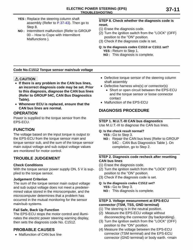
OPERATIONPower is supplied to the torque sensor from the EPS-ECU.
FUNCTIONThe voltage based on the input torque is output to the EPS-ECU from the torque sensor main and torque sensor sub, and the sum of the torque sensor main output voltage and sub output voltage values are monitored for motor control.
TROUBLE JUDGEMENTCheck ConditionsWith the torque sensor power supply ON, 5 V is sup-plied to the torque sensor.
Judgement CriterionThe sum of the torque sensor main output voltage and sub output voltage does not meet a predeter-mined value stored in the microcomputer, and the microcomputer determines that a problem has occurred in the mutual monitoring for the sensor main/sub systems.
Fail Safe, Back Up FunctionThe EPS-ECU stops the motor control and illumi-nates the electric power steering warning display, then sets the diagnosis code No. C1512.
PROBABLE CAUSES• Malfunction of CAN bus line
• Defective torque sensor of the steering column shaft assembly
• Defective harness wire(s) or connector(s)• Short or open circuit between the EPS-ECU
and the torque sensor or loose connector contact
• Malfunction of the EPS-ECU
DIAGNOSIS PROCEDURE
STEP 1. M.U.T.-III CAN bus diagnosticsUse M.U.T.-III to diagnose the CAN bus lines.
Q: Is the check result normal?YES : Go to Step 3.NO : Repair the CAN bus lines (Refer to GROUP
54C − CAN Bus Diagnostics Table ). On completion, go to Step 2.
STEP 2. Diagnosis code recheck after resetting CAN bus lines(1) Erase the diagnosis code.(2) Turn the ignition switch from the "LOCK" (OFF)
position to the "ON" position.(3) Check if the diagnosis code is set.
Q: Is the diagnosis codes C1512 set?YES : Go to Step 3.NO : This diagnosis is complete.
STEP 3. Voltage measurement at EPS-ECU connector (TSM, TSS, GND terminal)(1) The steering is in the neutral position.(2) Measure the EPS-ECU voltage without
disconnecting the connector (by backprobing).(3) Turn the ignition switch from the "LOCK" (OFF)
position to the "ON" position.(4) Measure the voltage between the EPS-ECU
connector (TSM terminal) and the EPS-ECU connector (GND terminal) or body earth. <main
TROUBLESHOOTINGELECTRIC POWER STEERING (EPS)37-12
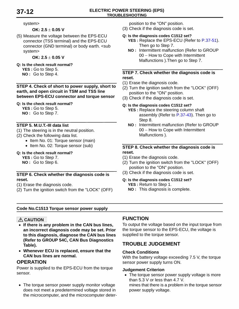
system>OK: 2.5 ± 0.05 V
(5) Measure the voltage between the EPS-ECU connector (TSS terminal) and the EPS-ECU connector (GND terminal) or body earth. <sub system>
OK: 2.5 ± 0.05 VQ: Is the check result normal?
YES : Go to Step 5.NO : Go to Step 4.
STEP 4. Check of short to power supply, short to earth, and open circuit in TSM and TSS line between EPS-ECU connector and torque sensorQ: Is the check result normal?
YES : Go to Step 5.NO : Go to Step 7.
STEP 5. M.U.T.-III data list(1) The steering is in the neutral position.(2) Check the following data list.
• Item No. 01: Torque sensor (main)• Item No. 02: Torque sensor (sub)
Q: Is the check result normal?YES : Go to Step 7.NO : Go to Step 6.
STEP 6. Check whether the diagnosis code is reset.(1) Erase the diagnosis code.(2) Turn the ignition switch from the "LOCK" (OFF)
position to the "ON" position.(3) Check if the diagnosis code is set.
Q: Is the diagnosis codes C1512 set?YES : Replace the EPS-ECU (Refer to P.37-51).
Then go to Step 7.NO : Intermittent malfunction (Refer to GROUP
00 − How to Cope with Intermittent Malfunctions ).Then go to Step 7.
STEP 7. Check whether the diagnosis code is reset.(1) Erase the diagnosis code.(2) Turn the ignition switch from the "LOCK" (OFF)
position to the "ON" position.(3) Check if the diagnosis code is set.
Q: Is the diagnosis codes C1512 set?YES : Replace the steering column shaft
assembly (Refer to P.37-43). Then go to Step 8.
NO : Intermittent malfunction (Refer to GROUP 00 − How to Cope with Intermittent Malfunctions ).
STEP 8. Check whether the diagnosis code is reset.(1) Erase the diagnosis code.(2) Turn the ignition switch from the "LOCK" (OFF)
position to the "ON" position.(3) Check if the diagnosis code is set.
Q: Is the diagnosis codes C1512 set?YES : Return to Step 1.NO : This diagnosis is complete.
Code No.C1513 Torque sensor power supply
CAUTION• If there is any problem in the CAN bus lines,
an incorrect diagnosis code may be set. Prior to this diagnosis, diagnose the CAN bus lines (Refer to GROUP 54C, CAN Bus Diagnostics Table).
• Whenever ECU is replaced, ensure that the CAN bus lines are normal.
OPERATIONPower is supplied to the EPS-ECU from the torque sensor.
FUNCTIONTo output the voltage based on the input torque from the torque sensor to the EPS-ECU, the voltage is supplied to the torque sensor.
TROUBLE JUDGEMENTCheck ConditionsWith the battery voltage exceeding 7.5 V, the torque sensor power supply turns ON.
Judgement Criterion• The torque sensor power supply voltage is more
than 5.3 V or less than 4.7 V.• The torque sensor power supply monitor voltage
does not meet a predetermined voltage stored in the microcomputer, and the microcomputer deter-
mines that there is a problem in the torque sensor power supply voltage.
TROUBLESHOOTINGELECTRIC POWER STEERING (EPS) 37-13
Fail Safe, Back Up FunctionThe EPS-ECU stops the motor control and illumi-nates the electric power steering warning display, then sets the diagnosis code No. C1513.
PROBABLE CAUSES• Malfunction of CAN bus line• Defective torque sensor of the steering column
shaft assembly• Defective harness wire(s) or connector(s)
• Short or open circuit between the EPS-ECU and the torque sensor or loose connector contact
• Open circuit between the body earth and the EPS-ECU or loose connector contact
• Malfunction of the EPS-ECU
DIAGNOSIS PROCEDURE
STEP 1. M.U.T.-III CAN bus diagnosticsUse M.U.T.-III to diagnose the CAN bus lines.
Q: Is the check result normal?YES : Go to Step 3.NO : Repair the CAN bus lines (Refer to GROUP
54C − CAN Bus Diagnostics Table ). On completion, go to Step 2.
STEP 2. Diagnosis code recheck after resetting CAN bus lines(1) Erase the diagnosis code.(2) Turn the ignition switch from the "LOCK" (OFF)
position to the "ON" position.(3) Check if the diagnosis code is set.
Q: Is the diagnosis code C1513 set?YES : Go to Step 3.NO : This diagnosis is complete.
STEP 3. Voltage measurement at EPS-ECU connector (TSV, TSE terminal)(1) The steering is in the neutral position.(2) Measure the EPS-ECU voltage without
disconnecting the connector (by backprobing).(3) Turn the ignition switch from the "LOCK" (OFF)
position to the "ON" position.(4) Measure the voltage between the EPS-ECU
connector (TSV terminal) and the EPS-ECU connector (TSE terminal).
OK: 5 ± 0.2 VQ: Is the check result normal?
YES : Go to Step 5.NO : Go to Step 4.
STEP 4. Check of short to power supply, short to earth, and open circuit in TSV and TSE line between EPS-ECU connector and torque sensorQ: Is the check result normal?
YES : Go to Step 5.NO : Go to Step 7.
STEP 5. M.U.T.-III data list(1) The steering is in the neutral position.(2) Check the following data list P.37-32.
• Item No. 03: Torque sensor (power supply)
Q: Is the check result normal?YES : Go to Step 7.NO : Go to Step 6.
STEP 6. Check whether the diagnosis code is reset.(1) Erase the diagnosis code.(2) Turn the ignition switch from the "LOCK" (OFF)
position to the "ON" position.(3) Check if the diagnosis code is set.
Q: Is the diagnosis code C1513 set?YES : Replace the EPS-ECU (Refer to P.37-51).
Then go to Step 7.NO : Intermittent malfunction (Refer to GROUP
00 − How to Cope with Intermittent Malfunctions ). Then go to Step 7.
STEP 7. Check whether the diagnosis code is reset.(1) Erase the diagnosis code.(2) Turn the ignition switch from the "LOCK" (OFF)
position to the "ON" position.(3) Check if the diagnosis code is set.
Q: Is the diagnosis code C1513 set?YES : Replace the steering column shaft
assembly (Refer to P.37-43). Then go to Step 8.
NO : Intermittent malfunction (Refer to GROUP 00 − How to Cope with Intermittent Malfunctions ).
STEP 8. Check whether the diagnosis code is reset.(1) Erase the diagnosis code.(2) Turn the ignition switch from the "LOCK" (OFF)
position to the "ON" position.(3) Check if the diagnosis code is set.
Q: Is the diagnosis code C1513 set?YES : Return to Step 1.NO : This diagnosis is complete.
TROUBLESHOOTINGELECTRIC POWER STEERING (EPS)37-14
Code No.C1514 Torque sensor power supply too low
CAUTION• If there is any problem in the CAN bus lines,
an incorrect diagnosis code may be set. Prior to this diagnosis, diagnose the CAN bus lines (Refer to GROUP 54C, CAN Bus Diagnostics Table).
• Whenever ECU is replaced, ensure that the CAN bus lines are normal.
OPERATIONPower is supplied to the torque sensor from the EPS-ECU.
FUNCTIONTo output the voltage based on the input torque from the torque sensor to the EPS-ECU, the voltage is supplied to the torque sensor.
TROUBLE JUDGEMENTCheck ConditionsTorque sensor power supply ON
Judgement CriterionThe torque sensor power supply monitor voltage does not meet a predetermined voltage stored in the microcomputer, and the microcomputer determines that there is a problem in the torque sensor power supply voltage.
Fail Safe, Back Up FunctionThe EPS-ECU stops the motor control and illumi-nates the electric power steering warning display, then sets the diagnosis code No. C1514.
PROBABLE CAUSES• Malfunction of CAN bus line• Defective torque sensor of the steering column
shaft assembly• Defective harness wire(s) or connector(s)
• Short or open circuit between the EPS-ECU and the torque sensor or loose connector contact
• Open circuit between the body earth and the EPS-ECU or loose connector contact
• Malfunction of the EPS-ECU
DIAGNOSIS PROCEDURE
STEP 1. M.U.T.-III CAN bus diagnosticsUse M.U.T.-III to diagnose the CAN bus lines.
Q: Is the check result normal?
YES : Go to Step 3.NO : Repair the CAN bus lines (Refer to GROUP
54C − CAN Bus Diagnostics Table ). On completion, go to Step 2.
STEP 2. Diagnosis code recheck after resetting CAN bus lines(1) Erase the diagnosis code.(2) Turn the ignition switch from the "LOCK" (OFF)
position to the "ON" position.(3) Check if the diagnosis code is set.
Q: Is the diagnosis code C1514 set?YES : Go to Step 3.NO : This diagnosis is complete.
STEP 3. Voltage measurement at EPS-ECU connector (TSV, TSE terminal)(1) The steering is in the neutral position.(2) Measure the EPS-ECU voltage without
disconnecting the connector (by backprobing).(3) Turn the ignition switch from the "LOCK" (OFF)
position to the "ON" position.(4) Measure the voltage between the EPS-ECU
connector (TSV terminal) and the EPS-ECU connector (TSE terminal).
OK: 5 ± 0.2 VQ: Is the check result normal?
YES : Go to Step 5.NO : Go to Step 4.
STEP 4. Check of short to earth, and open circuit in TSV and TSE line between EPS-ECU connector and torque sensorQ: Is the check result normal?
YES : Go to Step 5.NO : Go to Step 7.
STEP 5. M.U.T.-III data list(1) The steering is in the neutral position.(2) Check the following data list P.37-32.
• Item No. 03: Torque sensor(power supply)
Q: Is the check result normal?YES : Go to Step 7.NO : Go to Step 6.
STEP 6. Check whether the diagnosis code is reset.(1) Erase the diagnosis code.
TROUBLESHOOTINGELECTRIC POWER STEERING (EPS) 37-15
(2) Turn the ignition switch from the "LOCK" (OFF) position to the "ON" position.
(3) Check if the diagnosis code is set.
Q: Is the diagnosis code C1514 set?YES : Replace the EPS-ECU (Refer to
P.37-51).Then go to Step 7.NO : Intermittent malfunction (Refer to GROUP
00 − How to Cope with Intermittent Malfunctions ).
STEP 7. Check whether the diagnosis code is reset.(1) Erase the diagnosis code.(2) Turn the ignition switch from the "LOCK" (OFF)
position to the "ON" position.(3) Check if the diagnosis code is set.
Q: Is the diagnosis code C1514 set?YES : Replace the steering column shaft
assembly (Refer to P.37-43). Then go to Step 8.
NO : Intermittent malfunction (Refer to GROUP 00 − How to Cope with Intermittent Malfunctions ).
STEP 8. Check whether the diagnosis code is reset.(1) Erase the diagnosis code.(2) Turn the ignition switch from the "LOCK" (OFF)
position to the "ON" position.(3) Check if the diagnosis code is set.
Q: Is the diagnosis code C1514 set?YES : Return to Step 1.NO : This diagnosis is complete.
Code No.C1521 Motor turning angle (output) Code No.C1522 Motor turning angle range
CAUTION• If there is any problem in the CAN bus lines,
an incorrect diagnosis code may be set. Prior to this diagnosis, diagnose the CAN bus lines (Refer to GROUP 54C, CAN Bus Diagnostics Table).
• Whenever ECU is replaced, ensure that the CAN bus lines are normal.
OPERATIONPower is supplied to the resolver from the EPS-ECU.
FUNCTIONTo output the voltage based on the motor rotation angle to the EPS-ECU, the voltage is supplied to the resolver.
TROUBLE JUDGEMENTCheck ConditionsThe power supply circuit system diagnosis code (No. C1540, C1541) is not set.
Judgement CriterionThe resolver input voltage or the resolver output volt-age does not meet a predetermined voltage stored in the microcomputer, and the microcomputer deter-mines that there is a problem in the resolver system.
Fail Safe, Back Up FunctionThe EPS-ECU stops the motor control and illumi-nates the electric power steering warning display, then sets the diagnosis code No. C1521 and C1522.
PROBABLE CAUSES• Malfunction of CAN bus line• Defective resolver of the steering column shaft
assembly• Defective harness wire(s) or connector(s)
• Short or open circuit between the EPS-ECU and the resolver or loose connector contact
• Malfunction of the EPS-ECU
DIAGNOSIS PROCEDURE
STEP 1. M.U.T.-III CAN bus diagnosticsUse M.U.T.-III to diagnose the CAN bus lines.
Q: Is the check result normal?YES : Go to Step 3.NO : Repair the CAN bus lines (Refer to GROUP
54C − CAN Bus Diagnostics Table ). On completion, go to Step 2.
STEP 2. Diagnosis code recheck after resetting CAN bus lines(1) Erase the diagnosis code.(2) Turn the ignition switch from the "LOCK" (OFF)
position to the "ON" position.(3) Check if the diagnosis code is set.
Q: Is the diagnosis codes C1521 or C1522 set?YES : Go to Step 3.NO : This diagnosis is complete.
TROUBLESHOOTINGELECTRIC POWER STEERING (EPS)37-16
STEP 3. Check of short to power supply, short to earth, and open circuit in S1+, S3−, S2+, S4−, R1+, R2− line between EPS-ECU connector and resolverQ: Is the check result normal?
YES : Go to Step 4.NO : Go to Step 6.
STEP 4. M.U.T.-III data listCheck the following data list P.37-32.
• Item No. 04: Motor current• Item No. 05: Motor current (target)• Item No. 17: Motor electric angle• Item No. 18: Motor speed
Q: Is the check result normal?YES : Go to Step 5.NO : Go to Step 7.
STEP 5. Check whether the diagnosis code is reset.(1) Erase the diagnosis code.(2) Turn the ignition switch from the "LOCK" (OFF)
position to the "ON" position.(3) Check if the diagnosis code is set.
Q: Is the diagnosis codes C1521 or C1522 set?
YES : Replace the EPS-ECU (Refer to P.37-51).Then go to Step 6.
NO : Intermittent malfunction (Refer to GROUP 00 − How to Cope with Intermittent Malfunctions ).
STEP 6. Check whether the diagnosis code is reset.(1) Erase the diagnosis code.(2) Turn the ignition switch from the "LOCK" (OFF)
position to the "ON" position.(3) Check if the diagnosis code is set.
Q: Is the diagnosis codes C1521 or C1522 set?YES : Replace the steering column shaft
assembly (Refer to P.37-48).Then go to Step 7.
NO : Intermittent malfunction (Refer to GROUP 00 − How to Cope with Intermittent Malfunctions ).
STEP 7. Check whether the diagnosis code is reset.(1) Erase the diagnosis code.(2) Turn the ignition switch from the "LOCK" (OFF)
position to the "ON" position.(3) Check if the diagnosis code is set.
Q: Is the diagnosis codes C1521 or C1522 set?YES : Return to Step 1.NO : This diagnosis is complete.
Code No.C1530 Motor FET driver Code No.C1531 Motor current too low Code No.C1532 Motor output current too large Code No.C1533 Motor terminal initial voltage Code No.C1534 Motor terminal monitor voltage Code No.C1535 Motor output current Code No.C1536 Motor terminal voltage too high
CAUTION• If there is any problem in the CAN bus lines,
an incorrect diagnosis code may be set. Prior to this diagnosis, diagnose the CAN bus lines (Refer to GROUP 54C, CAN Bus Diagnostics Table).
• Whenever ECU is replaced, ensure that the CAN bus lines are normal.
OPERATIONPower is supplied to the motor from the EPS-ECU.
FUNCTIONThe voltage controlled by the torque sensor and resolver is supplied to the motor from the EPS-ECU.
TROUBLE JUDGEMENTCheck ConditionsThe battery voltage is more than 8 V or less than 17 V.
TROUBLESHOOTINGELECTRIC POWER STEERING (EPS) 37-17
Judgement CriterionThe motor voltage does not meet a predetermined voltage stored in the microcomputer, and the micro-computer determines that there is a problem in the motor system.
Fail Safe, Back Up FunctionThe EPS-ECU stops the motor control and illumi-nates the electric power steering warning display, then sets the diagnosis code No. C1530, C1531, C1532, C1533, C1534, C1535, and C1536.
PROBABLE CAUSES• Malfunction of CAN bus line• Defective motor of the steering column shaft
assembly• Defective harness wire(s) or connector(s)
• Short or open circuit between the EPS-ECU and the motor or loose connector contact
• Open circuit between the body earth and the EPS-ECU or loose connector contact
• Malfunction of the EPS-ECU
DIAGNOSIS PROCEDURE
STEP 1. M.U.T.-III CAN bus diagnosticsUse M.U.T.-III to diagnose the CAN bus lines.
Q: Is the check result normal?YES : Go to Step 3.NO : Repair the CAN bus lines (Refer to GROUP
54C − CAN Bus Diagnostics Table ). On completion, go to Step 2.
STEP 2. Diagnosis code recheck after resetting CAN bus lines(1) Erase the diagnosis code.(2) Turn the ignition switch from the "LOCK" (OFF)
position to the "ON" position.(3) Check if the diagnosis code is set.
Q: Is the diagnosis codes C1530,C1531,C1532,C1533,C1534,C1535 or C1536 set?YES : Go to Step 3.NO : This diagnosis is complete.
STEP 3. Check of short to power supply, short to earth, and open circuit in V, W, U line between EPS-ECU connector and motorQ: Is the check result normal?
YES : Go to Step 4.NO : Go to Step 7.
STEP 4. Check of open circuit in GND line between EPS-ECU connector and body earth connectorQ: Is the check result normal?
YES : Go to Step 5.NO : Go to Step 7.
STEP 5. M.U.T.-III data listCheck the following data list P.37-32.
• Item No. 04: Motor current• Item No. 05: Motor current (target)• Item No. 06: Motor current (unlimited target)• Item No. 17: Motor electric angle• Item No. 18: Motor speed• Item No. 19: Motor voltage• Item No. 25: Motor relay
Q: Is the check result normal?YES : Go to Step 8.NO : Go to Step 6.
STEP 6. Check whether the diagnosis code is reset.(1) Erase the diagnosis code.(2) Turn the ignition switch from the "LOCK" (OFF)
position to the "ON" position.(3) Check if the diagnosis code is set.
Q: Is the diagnosis codes C1530,C1531,C1532,C1533,C1534,C1535 or C1536 set?YES : Replace the EPS-ECU (Refer to
P.37-51).Then go to Step 7.NO : Intermittent malfunction (Refer to GROUP
00 − How to Cope with Intermittent Malfunctions ).
STEP 7. Check whether the diagnosis code is reset.(1) Erase the diagnosis code.(2) Turn the ignition switch from the "LOCK" (OFF)
position to the "ON" position.(3) Check if the diagnosis code is set.
Q: Is the diagnosis codes C1530,C1531,C1532,C1533,C1534,C1535 or C1536 set?YES : Replace the steering column shaft
assembly (Refer to P.37-48).Then go to Step 8.
NO : Intermittent malfunction (Refer to GROUP 00 − How to Cope with Intermittent Malfunctions ).
TROUBLESHOOTINGELECTRIC POWER STEERING (EPS)37-18
STEP 8. Check whether the diagnosis code is reset.(1) Erase the diagnosis code.(2) Turn the ignition switch from the "LOCK" (OFF)
position to the "ON" position.(3) Check if the diagnosis code is set.
Q: Is the diagnosis codes C1530,C1531,C1532,C1533,C1534,C1535 or C1536 set?YES : Return to Step 1.NO : This diagnosis is complete.
Code No.C1540 Power supply voltage too high
CAUTION• If there is any problem in the CAN bus lines,
an incorrect diagnosis code may be set. Prior to this diagnosis, diagnose the CAN bus lines (Refer to GROUP 54C, CAN Bus Diagnostics Table).
• Whenever ECU is replaced, ensure that the CAN bus lines are normal.
OPERATIONPower is supplied to the EPS-ECU from the battery or the ignition switch.
FUNCTIONTo control the steering column shaft assembly, the battery voltage is supplied to the EPS-ECU.
TROUBLE JUDGEMENTCheck Conditions
• Power supply voltage is more than 17 V.• The power supply voltage is more than a prede-
termined voltage stored in the microcomputer, and the microcomputer determines that there is a problem in the power supply system.
Judgement CriterionThe power supply monitor voltage does not meet a predetermined voltage stored in the microcomputer, and the microcomputer determines that there is a problem in the power supply system.
Fail Safe, Back Up FunctionThe EPS-ECU stops the motor control and illumi-nates the electric power steering warning display, then sets the diagnosis code No. C1540.
PROBABLE CAUSES• Malfunction of CAN bus line• Defective battery• Charging system failed• Malfunction of the EPS-ECU
DIAGNOSIS PROCEDURE
STEP 1. M.U.T.-III CAN bus diagnosticsUse M.U.T.-III to diagnose the CAN bus lines.
Q: Is the check result normal?YES : Go to Step 3NO : Repair the CAN bus lines (Refer to GROUP
54C − CAN Bus Diagnostics Table ). On completion, go to Step 2.
STEP 2. Diagnosis code recheck after resetting CAN bus lines(1) Erase the diagnosis code.(2) Turn the ignition switch from the "LOCK" (OFF)
position to the "ON" position.(3) Check if the diagnosis code is set.
Q: Is the diagnosis code C1540 set?YES : Go to Step 3NO : This diagnosis is complete.
STEP 3. Check the battery voltage.Start the engine and measure the battery voltage (Refer to GROUP 54A − Battery ).
Q: Is the check result normal?YES : Go to Step 4NO : Check the battery and repair if necessary
(Refer to GROUP 54A − Battery ).Then go to Step 7.
STEP 4. Check the charging system.Start the engine and measure the charging system (Refer to GROUP 16 − On−vehicle Service/Alterna-tor Output Line Voltage Drop Test ).
Q: Is the check result normal?YES : Go to Step 5NO : Check the charging system and repair if
necessary (Refer to GROUP 16 − Alternator Assembly ).Then go to Step 7.
TROUBLESHOOTINGELECTRIC POWER STEERING (EPS) 37-19
STEP 5. M.U.T.-III data listCheck the following data list P.37-32.
• Item No. 22: Power relay voltage• Item No. 23: Ignition voltage
Q: Is the check result normal?YES : Go to Step 7NO : Go to Step 6
STEP 6. Check whether the diagnosis code is reset.(1) Erase the diagnosis code.(2) Turn the ignition switch from the "LOCK" (OFF)
position to the "ON" position.(3) Check if the diagnosis code is set.
Q: Is the diagnosis code C1540 set?
YES : Replace the EPS-ECU (Refer to P.37-51).Then go to Step 7.
NO : Intermittent malfunction (Refer to GROUP 00 − How to Cope with Intermittent Malfunctions ).
STEP 7. Check whether the diagnosis code is reset.(1) Erase the diagnosis code.(2) Turn the ignition switch from the "LOCK" (OFF)
position to the "ON" position.(3) Check if the diagnosis code is set.
Q: Is the diagnosis code C1540 set?YES : Return to Step 1.NO : This diagnosis is complete.
Code No.C1541 Power supply voltage too low
CAUTION• If there is any problem in the CAN bus lines,
an incorrect diagnosis code may be set. Prior to this diagnosis, diagnose the CAN bus lines (Refer to GROUP 54C, CAN Bus Diagnostics Table).
• Whenever ECU is replaced, ensure that the CAN bus lines are normal.
OPERATIONPower is supplied to the EPS-ECU from the battery or the ignition switch.
FUNCTIONTo control the steering column shaft assembly, the battery voltage is supplied to the EPS-ECU for ener-gisation.
TROUBLE JUDGEMENTCheck ConditionsThe ETACS power supply circuit system diagnosis code is not set.
Judgement Criterion• Power supply voltage is less than 8V.• The power supply monitor voltage does not meet
a predetermined voltage stored in the microcom-puter, and the microcomputer determines that there is a problem in the power supply system.
Fail Safe, Back Up FunctionThe EPS-ECU tapers the motor control and illumi-nates the electric power steering warning display, then sets the diagnosis code No. C1541.
PROBABLE CAUSES• Malfunction of CAN bus line• Defective battery• Charging system failed• Defective harness wire(s) or connector(s)
• Short or open circuit between the EPS-ECU, the ETACS-ECU and the fusible link or loose connector contact
• Open circuit between the body earth and the EPS-ECU or loose connector contact
• Malfunction of the ETACS-ECU• Malfunction of the EPS-ECU
DIAGNOSIS PROCEDURE
STEP 1. M.U.T.-III CAN bus diagnosticsUse M.U.T.-III to diagnose the CAN bus lines.
Q: Is the check result normal?YES : Go to Step 3NO : Repair the CAN bus lines (Refer to GROUP
54C − CAN Bus Diagnostics Table ). On completion, go to Step 2.
STEP 2. Diagnosis code recheck after resetting CAN bus lines(1) Erase the diagnosis code.(2) Turn the ignition switch from the "LOCK" (OFF)
position to the "ON" position.(3) Check if the diagnosis code is set.
Q: Is the diagnosis code C1541 set?
TROUBLESHOOTINGELECTRIC POWER STEERING (EPS)37-20
YES : Go to Step 3NO : This diagnosis is complete.
STEP 3. Check the battery voltage.Start the engine and measure the battery voltage (Refer to GROUP 54A − Battery ).
Q: Is the check result normal?YES : Go to Step 4NO : Check the battery and repair if necessary
(Refer to GROUP 54A − Battery ). Then go to Step 10.
STEP 4. Check the charging system.Start the engine and measure the charging system (Refer to GROUP 16 − On−vehicle Service/Alterna-tor Output Line Voltage Drop Test )
Q: Is the check result normal?YES : Go to Step 5NO : Check the charging system and repair if
necessary (Refer to GROUP 16 − Alternator Assembly ).Then go to Step 10.
STEP 5. Voltage measurement at the EPS-ECU connector (IG1, +BB, GND terminal)(1) Measure the EPS-ECU voltage without
disconnecting the connector (by backprobing).(2) Turn the ignition switch from the "LOCK" (OFF)
position to the "ON" position.(3) Measure the voltage between the EPS-ECU
connector (IG1 terminal) and the EPS-ECU connector (GND terminal) or body earth.
OK: Approximately system voltage (4) Measure the voltage between the EPS-ECU
connector (+BB terminal) and the EPS-ECU connector (GND terminal) or body earth.
OK: Approximately system voltage Q: Is the check result normal?
YES : Go to Step 8NO : Go to Step 6
STEP 6. Check of short to power supply, short to earth, and open circuit in +BB line between fusible link and EPS-ECU connectorQ: Is the check result normal?
YES : Go to Step 7NO : Repair the fusible link, connector(s) or
wiring harness.
STEP 7. Check of short to power supply, short to earth, and open circuit in IG1 line between EPS-ECU connector and ETACS-ECU connectorQ: Is the check result normal?
YES : Go to Step 8NO : Repair the connector(s) or wiring harness.
STEP 8. M.U.T.-III data listCheck the following data list P.37-32.
• Item No. 22: Power relay voltage• Item No. 23: Ignition voltage
Q: Is the check result normal?YES : Go to Step 10NO : Go to Step 9
STEP 9. Check whether the diagnosis code is reset.(1) Erase the diagnosis code.(2) Turn the ignition switch from the "LOCK" (OFF)
position to the "ON" position.(3) Check if the diagnosis code is set.
Q: Is the diagnosis code C1541 set?YES : Replace the EPS-ECU (Refer to
P.37-51).Then go to Step 10.NO : Intermittent malfunction (Refer to GROUP
00 − How to Cope with Intermittent Malfunctions ).
STEP 10. Check whether the diagnosis code is reset.(1) Erase the diagnosis code.(2) Turn the ignition switch from the "LOCK" (OFF)
position to the "ON" position.(3) Check if the diagnosis code is set.
Q: Is the diagnosis code C1541 set?YES : Return to Step 1.NO : This diagnosis is complete.
TROUBLESHOOTINGELECTRIC POWER STEERING (EPS) 37-21
Code No.C1550 ECU internal error
CAUTION• If there is any problem in the CAN bus lines,
an incorrect diagnosis code may be set. Prior to this diagnosis, diagnose the CAN bus lines (Refer to GROUP 54C, CAN Bus Diagnostics Table).
• Whenever ECU is replaced, ensure that the CAN bus lines are normal.
OPERATIONPower is supplied to the EPS-ECU from the battery.
FUNCTIONThe motor current is controlled according to the infor-mation on motor and resolver, and the information on CAN bus.
TROUBLE JUDGEMENTJudgement CriterionThe system data is out of the prestored control range, and the microcomputer determines that there is an internal problem.
Fail Safe, Back Up FunctionThe EPS-ECU stops the motor control and illumi-nates the electric power steering warning display, then sets the diagnosis code No. C1550.
PROBABLE CAUSES• Malfunction of CAN bus line• Malfunction of the EPS-ECU
Code No.C1561 Engine revolution data (CAN)
CAUTION• If there is any problem in the CAN bus lines,
an incorrect diagnosis code may be set. Prior to this diagnosis, diagnose the CAN bus lines (Refer to GROUP 54C, CAN Bus Diagnostics Table).
• Whenever ECU is replaced, ensure that the CAN bus lines are normal.
OPERATIONEPS-ECU receives engine revolution signal from the engine-ECU.
FUNCTIONThe engine speed signal is sent to the EPS-ECU for motor control.
TROUBLE JUDGEMENTCheck Conditions
• The power supply circuit system diagnosis code (No. C1540, C1541) is not set.
• The engine circuit system diagnosis code is not set.
Judgement Criterion• The engine speed signal sent to the EPS-ECU is
no signal.• The engine speed signal is not sent from the
engine-ECU, and the microcomputer determines that there is a problem in the engine speed meas-urement system.
Fail Safe, Back Up Function• The EPS-ECU illuminates the electric power
steering warning display, and sets the diagnosis code No. C1561. Normally the assist operation is continued while the vehicle is driven, but deacti-vated after the vehicle stopped.
PROBABLE CAUSES• Malfunction of CAN bus line• Malfunction of the EPS-ECU• Malfunction of the engine-ECU
DIAGNOSIS PROCEDURE
STEP 1. M.U.T.-III CAN bus diagnosticsUse M.U.T.-III to diagnose the CAN bus lines.
Q: Is the check result normal?YES : Go to Step 3.NO : Repair the CAN bus lines (Refer to GROUP
54C − CAN Bus Diagnostics Table ). On completion, go to Step 2.
STEP 2. Diagnosis code recheck after resetting CAN bus lines(1) Erase the diagnosis code.(2) Turn the ignition switch from the "LOCK" (OFF)
position to the "ON" position.(3) Check if the diagnosis code is set.
Q: Is the diagnosis codes C1561 set?
TROUBLESHOOTINGELECTRIC POWER STEERING (EPS)37-22
YES : Go to Step 3.NO : This diagnosis is complete.
STEP 3. M.U.T.-III data listCheck the following service data P.37-32.
• Item No. 07: Engine speed
Q: Is the check result normal?YES : Go to Step 5.NO : Perform troubleshooting for engine-ECU
(Refer to GROUP 13A − Troubleshooting/Inspection Chart for Diagnosis code ). Then go to Step 4.
STEP 4. Check whether the diagnosis code is reset(1) Erase the diagnosis code.(2) Turn the ignition switch from the "LOCK" (OFF)
position to the "ON" position.
(3) Check if the diagnosis code is set.
Q: Is the diagnosis codes C1561 set?YES : Replace the EPS-ECU (Refer to P.37-51).
Then go to Step 5.NO : Intermittent malfunction (Refer to GROUP
00 − How to Cope with Intermittent Malfunction ).
STEP 5. Check whether the diagnosis code is reset.(1) Erase the diagnosis code.(2) Turn the ignition switch from the "LOCK" (OFF)
position to the "ON" position.(3) Check if the diagnosis code is set.
Q: Is the diagnosis codes C1561 set?YES : Return to Step 1.NO : This diagnosis is complete.
Code No.C1564 Vehicle speed data invalid
CAUTION• If there is any problem in the CAN bus lines,
an incorrect diagnosis code may be set. Prior to this diagnosis, diagnose the CAN bus lines (Refer to GROUP 54C, CAN Bus Diagnostics Table).
• Whenever ECU is replaced, ensure that the CAN bus lines are normal.
OPERATIONEPS-ECU receives vehicle speed signal from the engine-ECU.
FUNCTIONThe vehicle speed signal is sent to the EPS-ECU for motor control.
TROUBLE JUDGEMENTCheck Conditions
• The power supply circuit system diagnosis code (No. C1540, C1541) is not set.
• The engine circuit system diagnosis code is not set.
Judgement CriterionIf the microcomputer receives abnormal vehicle speed signal from the engine-ECU consecutively twice, it determines that the vehicle speed calcula-tion system is defective.
Fail Safe, Back Up FunctionThe EPS-ECU illuminates the electric power steering warning display, and sets the diagnosis code No. C1564 to limit assist operation.
PROBABLE CAUSES• Malfunction of CAN bus line• Malfunction of the EPS-ECU• Malfunction of the engine-ECU
DIAGNOSIS PROCEDURE
STEP 1. M.U.T.-III CAN bus diagnosticsUse M.U.T.-III to diagnose the CAN bus lines.
Q: Is the check result normal?YES : Go to Step 3NO : Repair the CAN bus lines (Refer to GROUP
54C − CAN Bus Diagnostics Table ). On completion, go to Step 2.
STEP 2. Diagnosis code recheck after resetting CAN bus lines(1) Erase the diagnosis code.(2) Turn the ignition switch from the "LOCK" (OFF)
position to the "ON" position.(3) Check if the diagnosis code is set.
Q: Is the diagnosis codes C1564 set?YES : Go to Step 3NO : This diagnosis is complete.
TROUBLESHOOTINGELECTRIC POWER STEERING (EPS) 37-23
STEP 3. M.U.T.-III data listCheck the following service data P.37-32.
• Item No. 08: Vehicle speed
Q: Is the check result normal?YES : Go to Step 5NO : Perform troubleshooting for engine-ECU
(Refer to GROUP 13A − Troubleshooting . Then go to Step 4.
STEP 4. Check whether the diagnosis code is reset(1) Erase the diagnosis code.(2) Turn the ignition switch from the "LOCK" (OFF)
position to the "ON" position.(3) Check if the diagnosis code is set.
Q: Is the diagnosis codes C1564 set?YES : Replace the EPS-ECU (Refer to P.37-51).
Then go to Step 5.NO : Intermittent malfunction (Refer to GROUP
00 − How to Cope with Intermittent Malfunction ).
STEP 5. Check whether the diagnosis code is reset.(1) Erase the diagnosis code.(2) Turn the ignition switch from the "LOCK" (OFF)
position to the "ON" position.(3) Check if the diagnosis code is set.
Q: Is the diagnosis codes C1564 set?YES : Return to Step 1.NO : This diagnosis is complete.
Code No.C1565 Engine revolution data invalid
CAUTION• If there is any problem in the CAN bus lines,
an incorrect diagnosis code may be set. Prior to this diagnosis, diagnose the CAN bus lines (Refer to GROUP 54C, CAN Bus Diagnostics Table).
• Whenever ECU is replaced, ensure that the CAN bus lines are normal.
OPERATIONEPS-ECU receives engine revolution signal from the engine-ECU.
FUNCTIONThe engine speed signal is sent to the EPS-ECU for motor control.
TROUBLE JUDGEMENTCheck Conditions
• The power supply circuit system diagnosis code (No. C1540, C1541) is not set.
• The engine circuit system diagnosis code is not set.
Judgement CriterionIf the microcomputer receives abnormal engine speed signal from the engine-ECU consecutively twice, it determines that the engine speed calculation system is defective.
Fail Safe, Back Up FunctionThe EPS-ECU displays the electric power steering warning symbol, and stores diagnosis code No. C1565 to limit the power assistance.
PROBABLE CAUSES• Malfunction of CAN bus line• Malfunction of the EPS-ECU• Malfunction of the engine-ECU
DIAGNOSIS PROCEDURE
STEP 1. M.U.T.-III CAN bus diagnosticsUse M.U.T.-III to diagnose the CAN bus lines.
Q: Is the check result normal?YES : Go to Step 3NO : Repair the CAN bus lines (Refer to GROUP
54C − CAN Bus Diagnostics Table ). On completion, go to Step 2.
STEP 2. Diagnosis code recheck after resetting CAN bus lines(1) Erase the diagnosis code.(2) Turn the ignition switch from the "LOCK" (OFF)
position to the "ON" position.(3) Check if the diagnosis code is set.
Q: Is the diagnosis codes C1565 set?YES : Go to Step 3NO : This diagnosis is complete.
STEP 3. M.U.T.-III data listCheck the following service data P.37-32.
• Item No. 07: Engine speed
Q: Is the check result normal?
TROUBLESHOOTINGELECTRIC POWER STEERING (EPS)37-24
YES : Go to Step 5NO : Perform troubleshooting for engine-ECU
(Refer to GROUP 13A − Troubleshooting/Inspection Chart for Diagnosis code . Then go to Step 4.
STEP 4. Check whether the diagnosis code is reset(1) Erase the diagnosis code.(2) Turn the ignition switch from the "LOCK" (OFF)
position to the "ON" position.(3) Check if the diagnosis code is set.
Q: Is the diagnosis codes C1565 set?
YES : Replace the EPS-ECU (Refer to P.37-51). Then go to Step 5.
NO : Intermittent malfunction (Refer to GROUP 00 − How to Cope with Intermittent Malfunction ).
STEP 5. Check whether the diagnosis code is reset.(1) Erase the diagnosis code.(2) Turn the ignition switch from the "LOCK" (OFF)
position to the "ON" position.(3) Check if the diagnosis code is set.
Q: Is the diagnosis codes C1565 set?YES : Return to Step 1.NO : This diagnosis is complete.
Code No.C1566 Invalid data received from AWC
CAUTION• If there is any problem in the CAN bus lines,
an incorrect diagnosis code may be set. Prior to this diagnosis, diagnose the CAN bus lines (Refer to GROUP 54C, CAN Bus Diagnostics Table).
• Whenever ECU is replaced, ensure that the CAN bus lines are normal.
OPERATIONAn additional torque signal is sent from the 4WD-ECU to the EPS-ECU.
FUNCTIONThe additional torque signal is sent to the EPS-ECU in order to control the motor.
TROUBLE JUDGEMENTCheck Conditions
• The power supply circuit system diagnosis code (No. C1540, C1541) is not set.
• The AWC circuit system diagnosis code is not set.
Judgement CriterionIf the microcomputer receives abnormal additional torque signal from the 4WD-ECU consecutively twice, it determines that the AWC system is defec-tive.
Fail Safe, Back Up FunctionThe EPS-ECU stores diagnosis code No. C1566.
PROBABLE CAUSES• Malfunction of CAN bus line
• Malfunction of the EPS-ECU• Malfunction of the 4WD-ECU
DIAGNOSIS PROCEDURE
STEP 1. M.U.T.-III CAN bus diagnosticsUse M.U.T.-III to diagnose the CAN bus lines.
Q: Is the check result normal?YES : Go to Step 3NO : Repair the CAN bus lines (Refer to GROUP
54C − CAN Bus Diagnostics Table ). On completion, go to Step 2.
STEP 2. Diagnosis code recheck after resetting CAN bus lines(1) Erase the diagnosis code.(2) Turn the ignition switch from the "LOCK" (OFF)
position to the "ON" position.(3) Check if the diagnosis code is set.
Q: Is the diagnosis codes C1566 set?YES : Go to Step 3NO : This diagnosis is complete.
STEP 3. M.U.T.-III data listCheck the following service data P.37-32.
• Item No. 09: Add torque indication status
Q: Is the check result normal?YES : Go to Step 5NO : Perform troubleshooting for 4WD-ECU
(Refer to GROUP 27C − Troubleshooting/Inspection Chart for Diagnosis code . Then go to Step 4.
TROUBLESHOOTINGELECTRIC POWER STEERING (EPS) 37-25
STEP 4. Check whether the diagnosis code is reset(1) Erase the diagnosis code.(2) Turn the ignition switch from the "LOCK" (OFF)
position to the "ON" position.(3) Check if the diagnosis code is set.
Q: Is the diagnosis codes C1566 set?YES : Replace the EPS-ECU (Refer to P.37-51).
Then go to Step 5.NO : Intermittent malfunction (Refer to GROUP
00 − How to Cope with Intermittent Malfunction ).
STEP 5. Check whether the diagnosis code is reset.(1) Erase the diagnosis code.(2) Turn the ignition switch from the "LOCK" (OFF)
position to the "ON" position.(3) Check if the diagnosis code is set.
Q: Is the diagnosis codes C1566 set?YES : Return to Step 1.NO : This diagnosis is complete.
Code No. C1657 Implausible coding data
CAUTION• If there is any problem in the CAN bus lines,
an incorrect diagnosis code may be set. Prior to this diagnosis, diagnose the CAN bus lines (Refer to GROUP 54C, CAN Bus Diagnostics Table).
• Whenever ECU is replaced, ensure that the CAN bus lines are normal.
OPERATIONEPS-ECU receives variant coding data from the ETACS-ECU.
FUNCTIONThe coding data is sent to the EPS-ECU for motor control.
TROUBLE JUDGEMENTCheck Conditions
• The power supply circuit system diagnosis code (No. C1540, C1541) is not set.
• The ETACS circuit system diagnosis code is not set.
Judgement Criterion• The coding data from the ETACS-ECU are not
matched twice consecutively.• The abnormal coding data is sent from the
ETACS-ECU, and the microcomputer determines that there is a problem in the system.
Fail Safe, Back Up FunctionThe EPS-ECU stores diagnosis code No. C1657.
PROBABLE CAUSES• Malfunction of CAN bus line• Malfunction of the EPS-ECU• Malfunction of the ETACS-ECU
DIAGNOSIS PROCEDURE
STEP 1. M.U.T.-III CAN bus diagnosticsUse M.U.T.-III to diagnose the CAN bus lines.
Q: Is the check result normal?YES : Go to Step 3NO : Repair the CAN bus lines (Refer to GROUP
54C − CAN Bus Diagnostics Table ). On completion, go to Step 2
STEP 2. Diagnosis code recheck after resetting CAN bus lines(1) Erase the diagnosis code.(2) Turn the ignition switch from the "LOCK" (OFF)
position to the "ON" position.(3) Check if the diagnosis code is set.
Q: Is the diagnosis codes C1657 set?YES : Go to Step 3NO : This diagnosis is complete.
STEP 3. M.U.T.-III other system diagnosis codeUse M.U.T.-III to check whether the ETACS-ECU-related or engine ECU-related diagno-sis code is set or not.
Q: Is any diagnosis code set?YES : Troubleshoot for the relevant diagnosis
code.NO : Go to Step 4
STEP 4. Check whether the diagnosis code is reset.(1) Erase the diagnosis code.(2) Turn the ignition switch from the "LOCK" (OFF)
position to the "ON" position.
TROUBLESHOOTINGELECTRIC POWER STEERING (EPS)37-26
(3) Check if the diagnosis code is set.
Q: Is the diagnosis codes C1657 set?YES : Replace the EPS-ECU (Refer to P.37-51).
Then go to Step 5.NO : Intermittent malfunction (Refer to GROUP
00 − How to Cope with Intermittent Malfunction .
STEP 5. Check whether the diagnosis code is reset.(1) Erase the diagnosis code.(2) Turn the ignition switch from the "LOCK" (OFF)
position to the "ON" position.(3) Check if the diagnosis code is set.
Q: Is the diagnosis codes C1657 set?YES : Return to Step 1.NO : This diagnosis is complete.
Code No. U0100 Engine CAN timeout Code No. U0114 4WD CAN timeout Code No. U0141 ETACS CAN timeout
CAUTION• If there is any problem in the CAN bus lines,
an incorrect diagnosis code may be set. Prior to this diagnosis, diagnose the CAN bus lines (Refer to GROUP 54C, CAN Bus Diagnostics Table).
• Whenever ECU is replaced, ensure that the CAN bus lines are normal.
OPERATIONThe signals from the engine-ECU, 4WD-ECU and ETACS-ECU are sent to the EPS-ECU.
FUNCTIONThe signals from the engine-ECU, 4WD-ECU and ETACS-ECU are sent to the EPS-ECU for motor control.
TROUBLE JUDGEMENTCheck Conditions
• The power supply circuit system diagnosis code (No. C1540, C1541) is not set.
• The diagnosis code related to engine circuit sys-tem, 4WD circuit system and ETACS circuit sys-tem is set.
Judgement CriterionThe signals from the engine-ECU, 4WD-ECU and ETACS-ECU are not sent, and the microcomputer determines that there is a problem in the system.
Fail Safe, Back Up Function• The EPS-ECU stores diagnosis code No. U0100,
U0114 or U0141. If diagnosis code No. U0100 is stored, the ECU displays the electric power steer-ing warning symbol to limit the power assistance.
PROBABLE CAUSES• Malfunction of CAN bus line
• Malfunction of the EPS-ECU• Malfunction of the engine-ECU• Malfunction of the ETACS-ECU• Malfunction of the 4WD-ECU
DIAGNOSIS PROCEDURE
STEP 1. M.U.T.-III CAN bus diagnosticsUse M.U.T.-III to diagnose the CAN bus lines.
Q: Is the check result normal?YES : Go to Step 3NO : Repair the CAN bus lines (Refer to GROUP
54C − CAN Bus Diagnostics Table ). On completion, go to Step 2.
STEP 2. Diagnosis code recheck after resetting CAN bus lines(1) Erase the diagnosis code.(2) Turn the ignition switch from the "LOCK" (OFF)
position to the "ON" position.(3) Check if the diagnosis code is set.
Q: Is the diagnosis codes U0100, U0114 or U0141 set?YES : Go to Step 3NO : This diagnosis is complete.
STEP 3. M.U.T.-III diagnosis codeUse M.U.T.-III to check if the same diagnosis code (time-out) is set in the other ECU.
Q: Is any diagnosis code set?YES (Code No. U0100 is set) : Replace the engine
ECU, and then go to Step 4.YES (Code No. U0114 is set) : Replace the
4WD-ECU, and then go to Step 4.YES (Code No. U0141 is set) : Replace the
ETACS-ECU, and then go to Step 4.NO (No diagnosis code is set.) : Go to Step 4
TROUBLESHOOTINGELECTRIC POWER STEERING (EPS) 37-27
STEP 4. Check whether the diagnosis code is reset(1) Erase the diagnosis code.(2) Turn the ignition switch from the LOCK (OFF)
position to the ON position.(3) Check if the diagnosis code is set.
Q: Is the diagnosis codes U0100, U0114 or U0141 set?YES : Replace the EPS-ECU (Refer to P.37-51 ).
Then go to Step 5.NO : Intermittent malfunction (Refer to GROUP
00 − How to Cope with Intermittent Malfunction ).
STEP 5. Check whether the diagnosis code is reset(1) Erase the diagnosis code.(2) Turn the ignition switch from the LOCK (OFF)
position to the ON position.(3) Check if the diagnosis code is set.
Q: Is the diagnosis codes U0100, U0114 or U0141 set?YES : Return to Step 1.NO : This diagnosis is complete.
Code No. U1073 Bus-off
CAUTION• If there is any problem in the CAN bus lines,
an incorrect diagnosis code may be set. Prior to this diagnosis, diagnose the CAN bus lines (Refer to GROUP 54C, CAN Bus Diagnostics Table).
• Whenever ECU is replaced, ensure that the CAN bus lines are normal.
OPERATIONSignals from the ECUs communicate with the EPS-ECU.
FUNCTIONThe signals from the ECUs communicate with the EPS-ECU for motor control.
TROUBLE JUDGEMENTCheck ConditionsIG1 voltage: 10 V or more
Judgement CriterionThe signals from the ECUs cannot communicate (bus off), and the microcomputer determines that there is a problem in the system.
Fail Safe, Back Up FunctionThe EPS-ECU displays the electric power steering warning symbol, and stores diagnosis code No. U1073.
PROBABLE CAUSES• Malfunction of CAN bus line• Malfunction of the EPS-ECU
Code No. U1190 No receive fault detect signal
CAUTION• If there is any problem in the CAN bus lines,
an incorrect diagnosis code may be set. Prior to this diagnosis, diagnose the CAN bus lines (Refer to GROUP 54C, CAN Bus Diagnostics Table).
• Whenever ECU is replaced, ensure that the CAN bus lines are normal.
OPERATIONA fault detection enabling/inhibiting signal is sent from the ETACS-ECU to the EPS-ECU.
TROUBLE JUDGEMENTCheck ConditionsIgnition switch: ON position
Judgement CriterionWhen the microcomputer cannot receive any fault detection enabling/inhibiting signal from the ETACS-ECU, it determines that there is a problem in the system.
Fail Safe, Back Up FunctionThe EPS-ECU stores diagnosis code No. U1190.
PROBABLE CAUSES• Malfunction of CAN bus line• Malfunction of the ETACS-ECU
TROUBLESHOOTINGELECTRIC POWER STEERING (EPS)37-28
Code No. U1195 Coding not completed Code No. U1197 Coding data unavailable
CAUTION• If there is any problem in the CAN bus lines,
an incorrect diagnosis code may be set. Prior to this diagnosis, diagnose the CAN bus lines (Refer to GROUP 54C, CAN Bus Diagnostics Table).
• Whenever ECU is replaced, ensure that the CAN bus lines are normal.
OPERATIONEPS-ECU receives variant coding data from the ETACS-ECU.
FUNCTIONThe coding data is sent to the EPS-ECU for motor control.
TROUBLE JUDGEMENTCheck Conditions
• The power supply circuit system diagnosis code (No. C1540, C1541) is not set.
• The ETACS circuit system diagnosis code is not set.
Judgement Criterion• The electric power steering-ECU coding is not
completed.• The abnormal coding data is sent from the
ETACS-ECU, and the microcomputer determines that there is a problem in the system.
Fail Safe, Back Up FunctionThe EPS-ECU prohibits the motor control, and stores diagnosis codes No. U1195 and U1197.
PROBABLE CAUSES• Malfunction of CAN bus line• Malfunction of the EPS-ECU• Malfunction of the ETACS-ECU
DIAGNOSIS PROCEDURE
STEP 1. M.U.T.-III CAN bus diagnosticsUse M.U.T.-III to diagnose the CAN bus lines.
Q: Is the check result normal?
YES : Go to Step 3NO : Repair the CAN bus lines (Refer to GROUP
54C − CAN Bus Diagnostics Table ). On completion, go to Step 2
STEP 2. Diagnosis code recheck after resetting CAN bus lines(1) Erase the diagnosis code.(2) Turn the ignition switch from the "LOCK" (OFF)
position to the "ON" position.(3) Check if the diagnosis code is set.
Q: Is the diagnosis codes U1195, U1197 set?YES : Go to Step 3NO : This diagnosis is complete.
STEP 3. M.U.T.-III other system diagnosis codeUse M.U.T.-III to check whether the ETACS-ECU-related or engine ECU-related diagno-sis code is set or not.
Q: Is any diagnosis code set?YES : Troubleshoot for the relevant diagnosis
code.NO : Go to Step 4
STEP 4. Check whether the diagnosis code is reset.(1) Erase the diagnosis code.(2) Turn the ignition switch from the "LOCK" (OFF)
position to the "ON" position.(3) Check if the diagnosis code is set.
Q: Is the diagnosis codes U1195, U1197 set?YES : Replace the EPS-ECU (Refer to P.37-51).
Then go to Step 5.NO : Intermittent malfunction (Refer to GROUP
00 − How to Cope with Intermittent Malfunction .
STEP 5. Check whether the diagnosis code is reset.(1) Erase the diagnosis code.(2) Turn the ignition switch from the "LOCK" (OFF)
position to the "ON" position.(3) Check if the diagnosis code is set.
Q: Is the diagnosis codes U1195, U1197 set?YES : Return to Step 1.NO : This diagnosis is complete.
TROUBLESHOOTINGELECTRIC POWER STEERING (EPS) 37-29
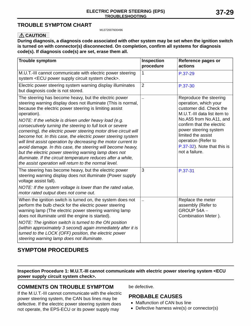
TROUBLE SYMPTOM CHARTM1372007600496
CAUTIONDuring diagnosis, a diagnosis code associated with other system may be set when the ignition switch is turned on with connector(s) disconnected. On completion, confirm all systems for diagnosis code(s). If diagnosis code(s) are set, erase them all.
Trouble symptom Inspection procedure
Reference pages or actions
M.U.T.-III cannot communicate with electric power steering system <ECU power supply circuit system check>.
1 P.37-29
Electric power steering system warning display illuminates but diagnosis code is not stored.
2 P.37-30
The steering has become heavy, but the electric power steering warning display does not illuminate (This is normal, because the electric power steering is limiting assist operation).NOTE: If the vehicle is driven under heavy load (e.g. consecutively turning the steering to full lock or severe cornering), the electric power steering motor drive circuit will become hot. In this case, the electric power steering system will limit assist operation by decreasing the motor current to avoid damage. In this case, the steering will become heavy, but the electric power steering warning lamp does not illuminate. If the circuit temperature reduces after a while, the assist operation will return to the normal level.
− Reproduce the steering operation, which your customer did. Check the M.U.T.-III data list item to No.A55 from No.A11, and confirm that the electric power steering system limited the assist operation (Refer to P.37-32). Note that this is not a failure.
The steering has become heavy, but the electric power steering warning display does not illuminate (Power supply voltage assist fall).NOTE: If the system voltage is lower than the rated value, motor rated output does not come out.
3 P.37-31
When the ignition switch is turned on, the system does not perform the bulb check for the electric power steering warning lamp (The electric power steering warning lamp does not illuminate until the engine is started).NOTE: The ignition switch is turned to the ON position (within approximately 3 second) again immediately after it is turned to the LOCK (OFF) position, the electric power steering warning lamp does not illuminate.
− Replace the meter assembly (Refer to GROUP 54A − Combination Meter ).
SYMPTOM PROCEDURES
Inspection Procedure 1: M.U.T.-III cannot communicate with electric power steering system <ECU power supply circuit system check>.
COMMENTS ON TROUBLE SYMPTOMIf the M.U.T.-III cannot communicate with the electric power steering system, the CAN bus lines may be defective. If the electric power steering system does not operate, the EPS-ECU or its power supply may
be defective.
PROBABLE CAUSES• Malfunction of CAN bus line• Defective harness wire(s) or connector(s)
TROUBLESHOOTINGELECTRIC POWER STEERING (EPS)37-30
• Short or open circuit between the EPS-ECU and the ETACS-ECU, the fusible link or loose connector contact
• Open circuit between the body earth and the EPS-ECU or loose connector contact
• Malfunction of the ETACS-ECU• Malfunction of the EPS-ECU
DIAGNOSIS PROCEDURE
STEP 1. M.U.T.-III CAN bus diagnosticsUse M.U.T.-III to diagnose the CAN bus lines.
Q: Is the check result normal?YES : Go to Step 2.NO : Repair the CAN bus lines (Refer to GROUP
54C − CAN Bus Diagnostics Table ).
STEP 2. Voltage measurement at the EPS-ECU connector (IG1, +BB, GND terminal)(1) Measure the EPS-ECU voltage without
disconnecting the connector (by backprobing).(2) Turn the ignition switch from the "LOCK" (OFF)
position to the "ON" position.(3) Measure the voltage between the EPS-ECU
connector (IG1 terminal) and the EPS-ECU connector (GND terminal) or body earth.
OK: Approximately system voltage (4) Measure the voltage between the EPS-ECU
connector (+BB terminal) and the EPS-ECU
connector (GND terminal) or body earth.OK: Approximately system voltage
Q: Is the check result normal?YES : Go to Step 5.NO : Go to Step 3.
STEP 3. Check of short to power supply, short to earth, and open circuit in +BB line between fusible link and EPS-ECU connectorQ: Is the check result normal?
YES : Go to Step 4.NO : Repair the fusible link, connector(s) or
wiring harness.
STEP 4. Check of short to power supply, short to earth, and open circuit in IG1 line between EPS-ECU connector and ETACS-ECU connectorQ: Is the check result normal?
YES : Go to Step 5.NO : Repair the connector(s) or wiring harness.
STEP 5. Retest the systemQ: Is the check result normal?
YES : Intermittent malfunction (Refer to GROUP 00 − How to Cope with Intermittent Malfunction ).
NO : Replace the EPS-ECU (Refer to P.37-51).
Inspection Procedure 2: Electric power steering system warning display illuminates but diagnosis code is not stored.
COMMENTS ON TROUBLE SYMPTOMThe CAN bus lines may be defective. If the electric power steering system does not operate, the combi-nation meter or the EPS-ECU may be defective.
PROBABLE CAUSES• Malfunction of CAN bus line• Defective harness wire(s) or connector(s)
• Short or open circuit between the EPS-ECU and the ETACS-ECU, the fusible link or loose connector contact
• Open circuit between the body earth and the EPS-ECU or loose connector contact
• Malfunction of the ETACS-ECU• Malfunction of the combination meter• Malfunction of the EPS-ECU
DIAGNOSIS PROCEDURE
STEP 1. M.U.T.-III CAN bus diagnosticsUse M.U.T.-III to diagnose the CAN bus lines.
Q: Is the check result normal?YES : Go to Step 2.NO : Repair the CAN bus lines (Refer to GROUP
54C − CAN Bus Diagnostics Table ).
STEP 2. Check by M.U.T.-III "Special Function"Using M.U.T.-III, select "Test" from the special func-tion of the combination meter. Execute the following item to check the liquid crystal display. (Refer to GROUP 54A − Combination Meter )
• Item 2: LCD(AUTO)
Q: Is the check result normal?
TROUBLESHOOTINGELECTRIC POWER STEERING (EPS) 37-31
YES : Go to Step 3.NO : Replace the combination meter.
STEP 3. Voltage measurement at the EPS-ECU connector (IG1, +BB, GND terminal)(1) Measure the EPS-ECU voltage without
disconnecting the connector (by backprobing).(2) Turn the ignition switch from the "LOCK" (OFF)
position to the "ON" position.(3) Measure the voltage between the EPS-ECU
connector (IG1 terminal) and the EPS-ECU connector (GND terminal) or body earth.
OK: Approximately system voltage (4) Measure the voltage between the EPS-ECU
connector (+BB terminal) and the EPS-ECU connector (GND terminal) or body earth.
OK: Approximately system voltage Q: Is the check result normal?
YES : Go to Step 6.NO : Go to Step 4.
STEP 4. Check of short to power supply, short to earth, and open circuit in +BB line between fusible link and EPS-ECU connectorQ: Is the check result normal?
YES : Go to Step 5.NO : Repair the fusible link, connector(s) or
wiring harness.
STEP 5. Check of short to power supply, short to earth, and open circuit in IG1 line between EPS-ECU connector and ETACS-ECU connectorQ: Is the check result normal?
YES : Go to Step 6.NO : Repair the connector(s) or wiring harness.
STEP 6. Retest the systemQ: Is the check result normal?
YES : Intermittent malfunction (Refer to GROUP 00 − How to Cope with Intermittent Malfunction ).
NO : Replace the EPS-ECU (Refer to P.37-51).
Inspection Procedure 3: The steering has become heavy, but electric power steering warning display does not illuminate. (Power supply voltage assist fall)
COMMENTS ON TROUBLE SYMPTOMIntermittent failure may be present in the power sup-ply system. Check the battery and the alternator to confirm that normal direct voltage flows.
PROBABLE CAUSES• Malfunction of CAN bus line• Defective battery• Charging system failed• Malfunction of the EPS-ECU
DIAGNOSIS PROCEDURE
STEP 1. M.U.T.-III CAN bus diagnosticsUse M.U.T.-III to diagnose the CAN bus lines.
Q: Is the check result normal?YES : Go to Step 2.NO : Repair the CAN bus lines (Refer to GROUP
54C − CAN Bus Diagnostics Table ).
STEP 2. M.U.T.-III data listCheck the following service data P.37-32.
• Item No. B11: Odometer:rec.V1• Item No. B12: Power relay voltage:rec V1• Item No. B13: Vehicle speed:rec.V1• Item No. B21: Odometer:rec.V2• Item No. B22: Power relay voltage:rec V2• Item No. B23: Vehicle speed:rec.V2• Item No. B31: Odometer:rec.V3• Item No. B32: Power relay voltage:rec V3• Item No. B33: Vehicle speed:rec.V3• Item No. B41: Odometer:rec.V4• Item No. B42: Power relay voltage:rec V4• Item No. B43: Vehicle speed:rec.V4• Item No. B51: Odometer:rec.V5• Item No. B52: Power relay voltage:rec V5• Item No. B53: Vehicle speed:rec.V5
Q: Is the check result normal?YES : Go to Step 3.NO : Check the combination meter and repair if
necessary (Refer to GROUP 54A−combination meter ). Then go to Step 5.
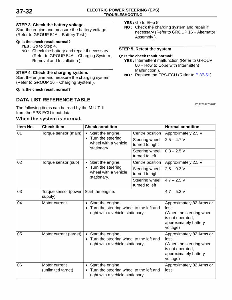
TROUBLESHOOTINGELECTRIC POWER STEERING (EPS)37-32
STEP 3. Check the battery voltage.Start the engine and measure the battery voltage (Refer to GROUP 54A − Battery Test ).
Q: Is the check result normal?YES : Go to Step 4.NO : Check the battery and repair if necessary
(Refer to GROUP 54A − Charging System , Removal and Installation ).
STEP 4. Check the charging system.Start the engine and measure the charging system (Refer to GROUP 16 − Charging System ).
Q: Is the check result normal?
YES : Go to Step 5.NO : Check the charging system and repair if
necessary (Refer to GROUP 16 − Alternator Assembly ).
STEP 5. Retest the systemQ: Is the check result normal?
YES : Intermittent malfunction (Refer to GROUP 00 − How to Cope with Intermittent Malfunction ).
NO : Replace the EPS-ECU (Refer to P.37-51).
DATA LIST REFERENCE TABLEM1372007700200
The following items can be read by the M.U.T.-III from the EPS-ECU input data.When the system is normal.Item No. Check item Check condition Normal condition01 Torque sensor (main) • Start the engine.
• Turn the steering wheel with a vehicle stationary.
Centre position Approximately 2.5 VSteering wheel turned to right
2.5 − 4.7 V
Steering wheel turned to left
0.3 − 2.5 V
02 Torque sensor (sub) • Start the engine.• Turn the steering
wheel with a vehicle stationary.
Centre position Approximately 2.5 VSteering wheel turned to right
2.5 − 0.3 V
Steering wheel turned to left
4.7 − 2.5 V
03 Torque sensor (power supply)
Start the engine. 4.7 − 5.3 V
04 Motor current • Start the engine.• Turn the steering wheel to the left and
right with a vehicle stationary.
Approximately 82 Arms or less(When the steering wheel is not operated, approximately battery voltage)
05 Motor current (target) • Start the engine.• Turn the steering wheel to the left and
right with a vehicle stationary.
Approximately 82 Arms or less(When the steering wheel is not operated, approximately battery voltage)
06 Motor current (unlimited target)
• Start the engine.• Turn the steering wheel to the left and
right with a vehicle stationary.
Approximately 82 Arms or less
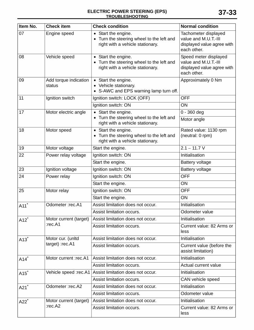
TROUBLESHOOTINGELECTRIC POWER STEERING (EPS) 37-33
07 Engine speed • Start the engine.• Turn the steering wheel to the left and
right with a vehicle stationary.
Tachometer displayed value and M.U.T.-III displayed value agree with each other.
08 Vehicle speed • Start the engine.• Turn the steering wheel to the left and
right with a vehicle stationary.
Speed meter displayed value and M.U.T.-III displayed value agree with each other.
09 Add torque indication status
• Start the engine.• Vehicle stationary.• S-AWC and EPS warning lamp turn off.
Approximately 0 Nm
11 Ignition switch Ignition switch: LOCK (OFF) OFFIgnition switch: ON ON
17 Motor electric angle • Start the engine.• Turn the steering wheel to the left and
right with a vehicle stationary.
0 - 360 degMotor angle
18 Motor speed • Start the engine.• Turn the steering wheel to the left and
right with a vehicle stationary.
Rated value: 1130 rpm (neutral: 0 rpm)
19 Motor voltage Start the engine. 2.1 − 11.7 V22 Power relay voltage Ignition switch: ON Initialisation
Start the engine. Battery voltage23 Ignition voltage Ignition switch: ON Battery voltage24 Power relay Ignition switch: ON OFF
Start the engine. ON25 Motor relay Ignition switch: ON OFF
Start the engine. ON
A11* Odometer :rec.A1 Assist limitation does not occur. InitialisationAssist limitation occurs. Odometer value
A12* Motor current (target) :rec.A1
Assist limitation does not occur. InitialisationAssist limitation occurs. Current value: 82 Arms or
less
A13* Motor cur. (unltd target) :rec.A1
Assist limitation does not occur. InitialisationAssist limitation occurs. Current value (before the
assist limitation)
A14* Motor current :rec.A1 Assist limitation does not occur. InitialisationAssist limitation occurs. Actual current value
A15* Vehicle speed :rec.A1 Assist limitation does not occur. InitialisationAssist limitation occurs. CAN vehicle speed
A21* Odometer :rec.A2 Assist limitation does not occur. InitialisationAssist limitation occurs. Odometer value
A22* Motor current (target) :rec.A2
Assist limitation does not occur. InitialisationAssist limitation occurs. Current value: 82 Arms or
less
Item No. Check item Check condition Normal condition
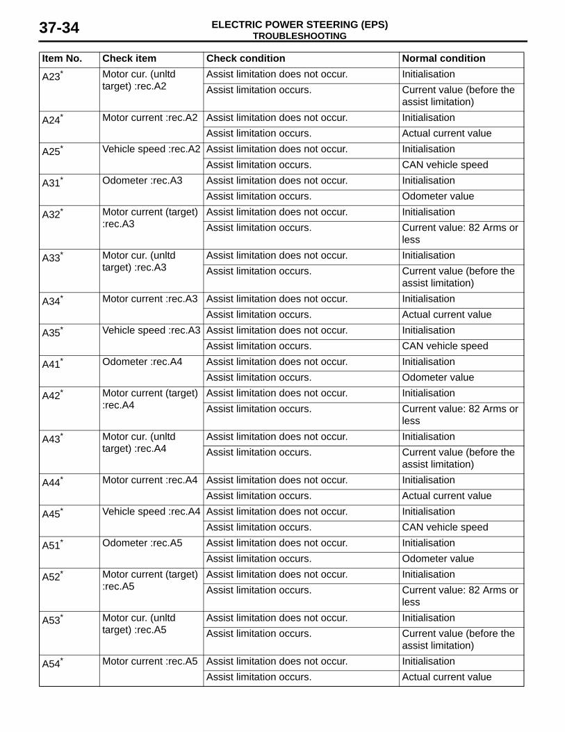
TROUBLESHOOTINGELECTRIC POWER STEERING (EPS)37-34
A23* Motor cur. (unltd target) :rec.A2
Assist limitation does not occur. InitialisationAssist limitation occurs. Current value (before the
assist limitation)
A24* Motor current :rec.A2 Assist limitation does not occur. InitialisationAssist limitation occurs. Actual current value
A25* Vehicle speed :rec.A2 Assist limitation does not occur. InitialisationAssist limitation occurs. CAN vehicle speed
A31* Odometer :rec.A3 Assist limitation does not occur. InitialisationAssist limitation occurs. Odometer value
A32* Motor current (target) :rec.A3
Assist limitation does not occur. InitialisationAssist limitation occurs. Current value: 82 Arms or
less
A33* Motor cur. (unltd target) :rec.A3
Assist limitation does not occur. InitialisationAssist limitation occurs. Current value (before the
assist limitation)
A34* Motor current :rec.A3 Assist limitation does not occur. InitialisationAssist limitation occurs. Actual current value
A35* Vehicle speed :rec.A3 Assist limitation does not occur. InitialisationAssist limitation occurs. CAN vehicle speed
A41* Odometer :rec.A4 Assist limitation does not occur. InitialisationAssist limitation occurs. Odometer value
A42* Motor current (target) :rec.A4
Assist limitation does not occur. InitialisationAssist limitation occurs. Current value: 82 Arms or
less
A43* Motor cur. (unltd target) :rec.A4
Assist limitation does not occur. InitialisationAssist limitation occurs. Current value (before the
assist limitation)
A44* Motor current :rec.A4 Assist limitation does not occur. InitialisationAssist limitation occurs. Actual current value
A45* Vehicle speed :rec.A4 Assist limitation does not occur. InitialisationAssist limitation occurs. CAN vehicle speed
A51* Odometer :rec.A5 Assist limitation does not occur. InitialisationAssist limitation occurs. Odometer value
A52* Motor current (target) :rec.A5
Assist limitation does not occur. InitialisationAssist limitation occurs. Current value: 82 Arms or
less
A53* Motor cur. (unltd target) :rec.A5
Assist limitation does not occur. InitialisationAssist limitation occurs. Current value (before the
assist limitation)
A54* Motor current :rec.A5 Assist limitation does not occur. InitialisationAssist limitation occurs. Actual current value
Item No. Check item Check condition Normal condition
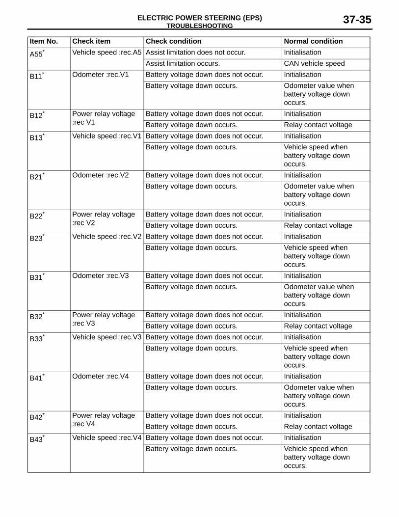
TROUBLESHOOTINGELECTRIC POWER STEERING (EPS) 37-35
A55* Vehicle speed :rec.A5 Assist limitation does not occur. InitialisationAssist limitation occurs. CAN vehicle speed
B11* Odometer :rec.V1 Battery voltage down does not occur. InitialisationBattery voltage down occurs. Odometer value when
battery voltage down occurs.
B12* Power relay voltage :rec V1
Battery voltage down does not occur. InitialisationBattery voltage down occurs. Relay contact voltage
B13* Vehicle speed :rec.V1 Battery voltage down does not occur. InitialisationBattery voltage down occurs. Vehicle speed when
battery voltage down occurs.
B21* Odometer :rec.V2 Battery voltage down does not occur. InitialisationBattery voltage down occurs. Odometer value when
battery voltage down occurs.
B22* Power relay voltage :rec V2
Battery voltage down does not occur. InitialisationBattery voltage down occurs. Relay contact voltage
B23* Vehicle speed :rec.V2 Battery voltage down does not occur. InitialisationBattery voltage down occurs. Vehicle speed when
battery voltage down occurs.
B31* Odometer :rec.V3 Battery voltage down does not occur. InitialisationBattery voltage down occurs. Odometer value when
battery voltage down occurs.
B32* Power relay voltage :rec V3
Battery voltage down does not occur. InitialisationBattery voltage down occurs. Relay contact voltage
B33* Vehicle speed :rec.V3 Battery voltage down does not occur. InitialisationBattery voltage down occurs. Vehicle speed when
battery voltage down occurs.
B41* Odometer :rec.V4 Battery voltage down does not occur. InitialisationBattery voltage down occurs. Odometer value when
battery voltage down occurs.
B42* Power relay voltage :rec V4
Battery voltage down does not occur. InitialisationBattery voltage down occurs. Relay contact voltage
B43* Vehicle speed :rec.V4 Battery voltage down does not occur. InitialisationBattery voltage down occurs. Vehicle speed when
battery voltage down occurs.
Item No. Check item Check condition Normal condition
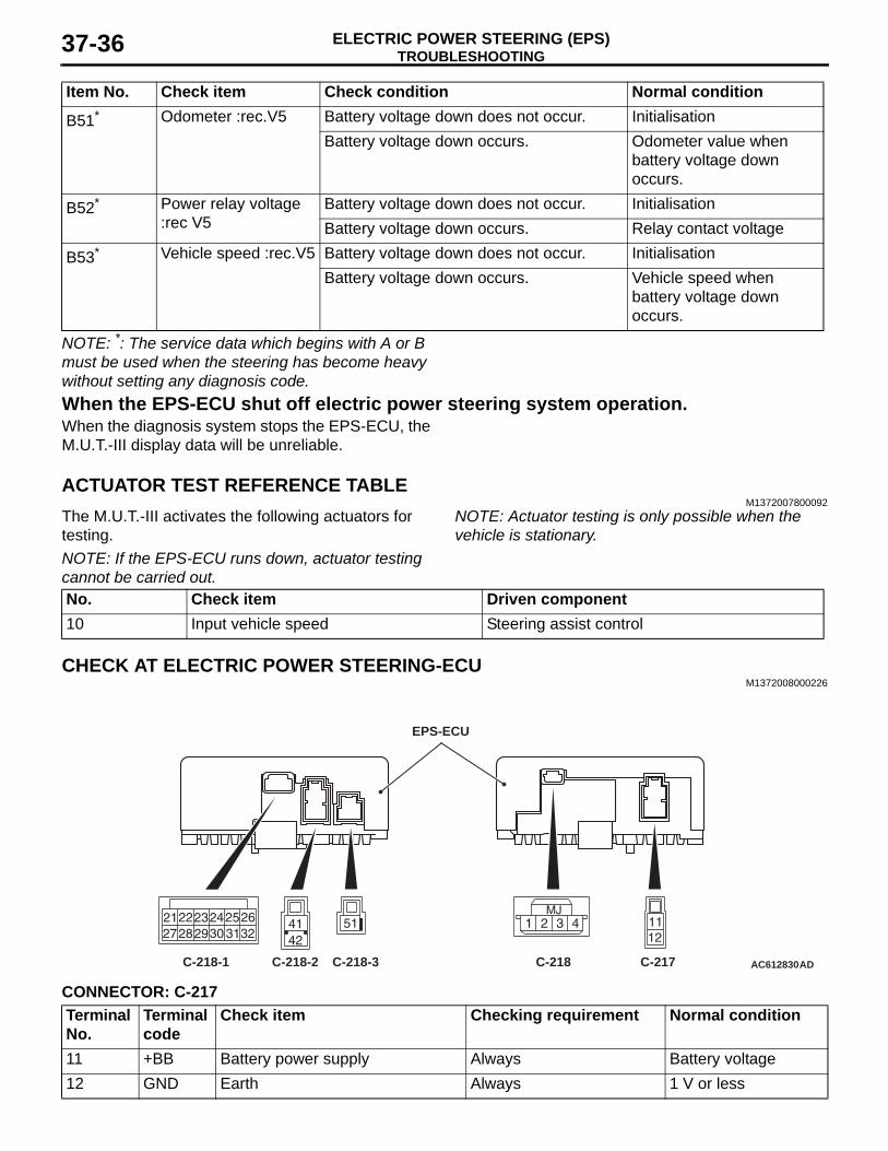
TROUBLESHOOTINGELECTRIC POWER STEERING (EPS)37-36
NOTE: *: The service data which begins with A or B must be used when the steering has become heavy without setting any diagnosis code.When the EPS-ECU shut off electric power steering system operation.When the diagnosis system stops the EPS-ECU, the M.U.T.-III display data will be unreliable.
ACTUATOR TEST REFERENCE TABLEM1372007800092
The M.U.T.-III activates the following actuators for testing.NOTE: If the EPS-ECU runs down, actuator testing cannot be carried out.
NOTE: Actuator testing is only possible when the vehicle is stationary.
No. Check item Driven component10 Input vehicle speed Steering assist control
CHECK AT ELECTRIC POWER STEERING-ECUM1372008000226
AC612830ADC-218-1 C-217C-218C-218-3C-218-2
EPS-ECU
CONNECTOR: C-217Terminal No.
Terminal code
Check item Checking requirement Normal condition
11 +BB Battery power supply Always Battery voltage12 GND Earth Always 1 V or less
B51* Odometer :rec.V5 Battery voltage down does not occur. InitialisationBattery voltage down occurs. Odometer value when
battery voltage down occurs.
B52* Power relay voltage :rec V5
Battery voltage down does not occur. InitialisationBattery voltage down occurs. Relay contact voltage
B53* Vehicle speed :rec.V5 Battery voltage down does not occur. InitialisationBattery voltage down occurs. Vehicle speed when
battery voltage down occurs.
Item No. Check item Check condition Normal condition
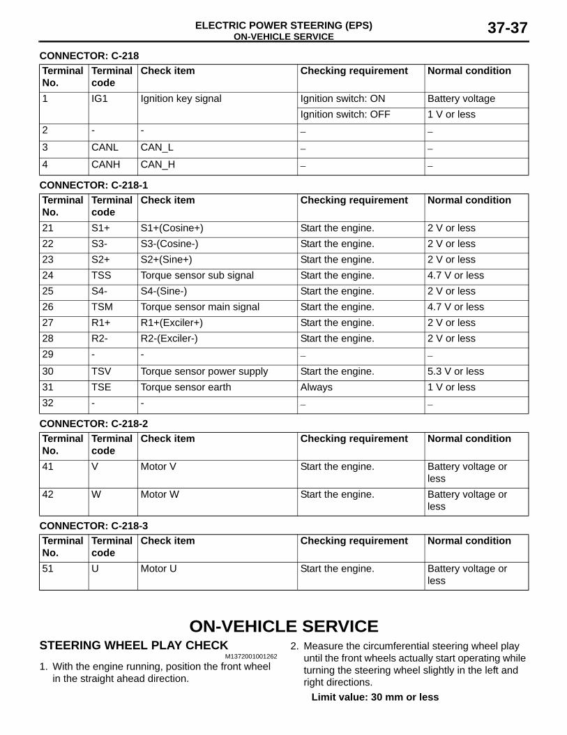
ON-VEHICLE SERVICEELECTRIC POWER STEERING (EPS) 37-37
CONNECTOR: C-218Terminal No.
Terminal code
Check item Checking requirement Normal condition
1 IG1 Ignition key signal Ignition switch: ON Battery voltageIgnition switch: OFF 1 V or less
2 - - − −
3 CANL CAN_L − −
4 CANH CAN_H − −
CONNECTOR: C-218-1Terminal No.
Terminal code
Check item Checking requirement Normal condition
21 S1+ S1+(Cosine+) Start the engine. 2 V or less22 S3- S3-(Cosine-) Start the engine. 2 V or less23 S2+ S2+(Sine+) Start the engine. 2 V or less24 TSS Torque sensor sub signal Start the engine. 4.7 V or less25 S4- S4-(Sine-) Start the engine. 2 V or less26 TSM Torque sensor main signal Start the engine. 4.7 V or less27 R1+ R1+(Exciler+) Start the engine. 2 V or less28 R2- R2-(Exciler-) Start the engine. 2 V or less29 - - − −
30 TSV Torque sensor power supply Start the engine. 5.3 V or less31 TSE Torque sensor earth Always 1 V or less32 - - − −
CONNECTOR: C-218-2Terminal No.
Terminal code
Check item Checking requirement Normal condition
41 V Motor V Start the engine. Battery voltage or less
42 W Motor W Start the engine. Battery voltage or less
CONNECTOR: C-218-3Terminal No.
Terminal code
Check item Checking requirement Normal condition
51 U Motor U Start the engine. Battery voltage or less
ON-VEHICLE SERVICESTEERING WHEEL PLAY CHECK
M1372001001262
1. With the engine running, position the front wheel in the straight ahead direction.
2. Measure the circumferential steering wheel play until the front wheels actually start operating while turning the steering wheel slightly in the left and right directions.
Limit value: 30 mm or less
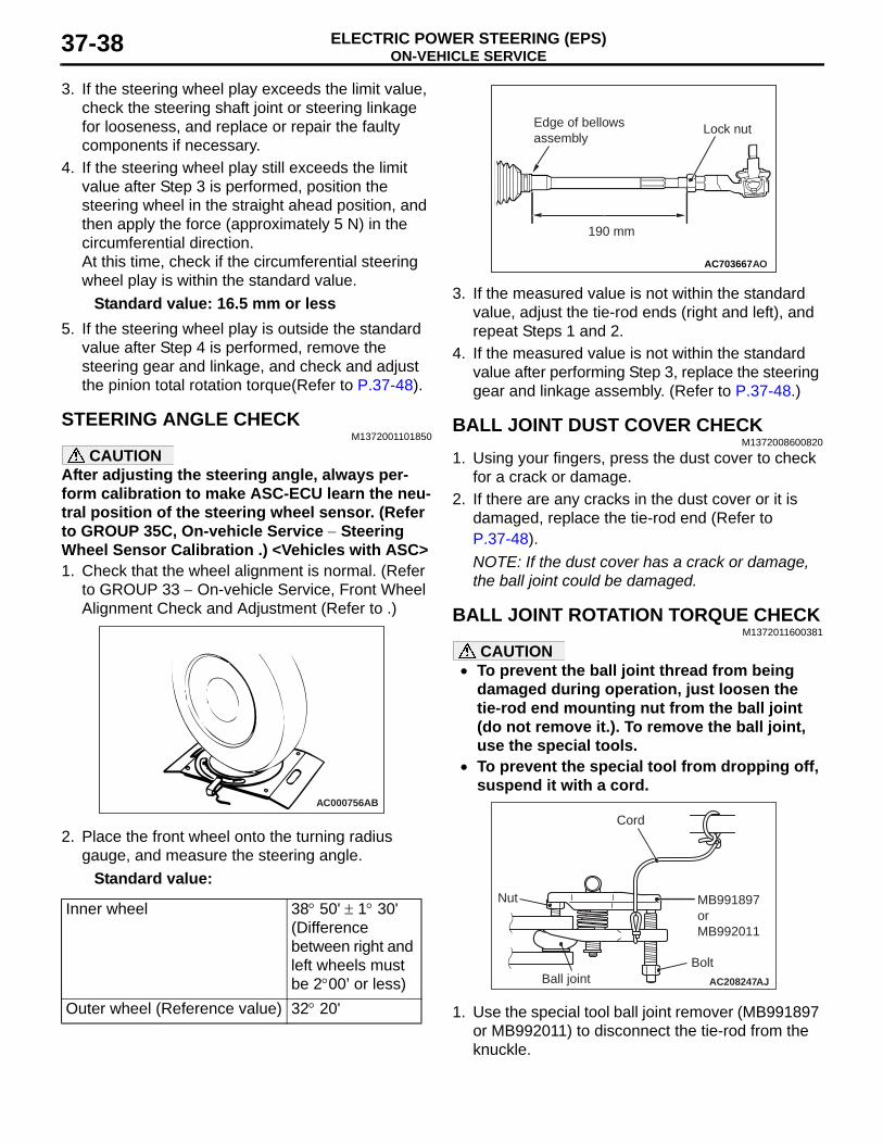
ON-VEHICLE SERVICEELECTRIC POWER STEERING (EPS)37-38
3. If the steering wheel play exceeds the limit value, check the steering shaft joint or steering linkage for looseness, and replace or repair the faulty components if necessary.
4. If the steering wheel play still exceeds the limit value after Step 3 is performed, position the steering wheel in the straight ahead position, and then apply the force (approximately 5 N) in the circumferential direction. At this time, check if the circumferential steering wheel play is within the standard value.
Standard value: 16.5 mm or less5. If the steering wheel play is outside the standard
value after Step 4 is performed, remove the steering gear and linkage, and check and adjust the pinion total rotation torque(Refer to P.37-48).
STEERING ANGLE CHECKM1372001101850
CAUTIONAfter adjusting the steering angle, always per-form calibration to make ASC-ECU learn the neu-tral position of the steering wheel sensor. (Refer to GROUP 35C, On-vehicle Service − Steering Wheel Sensor Calibration .) <Vehicles with ASC>1. Check that the wheel alignment is normal. (Refer
to GROUP 33 − On-vehicle Service, Front Wheel Alignment Check and Adjustment (Refer to .)
AC000756AB
2. Place the front wheel onto the turning radius gauge, and measure the steering angle.
Standard value:
Inner wheel 38° 50' ± 1° 30'(Difference between right and left wheels must be 2°00’ or less)
Outer wheel (Reference value) 32° 20'
AC703667
190 mm
AO
Lock nutEdge of bellowsassembly
3. If the measured value is not within the standard value, adjust the tie-rod ends (right and left), and repeat Steps 1 and 2.
4. If the measured value is not within the standard value after performing Step 3, replace the steering gear and linkage assembly. (Refer to P.37-48.)
BALL JOINT DUST COVER CHECKM1372008600820
1. Using your fingers, press the dust cover to check for a crack or damage.
2. If there are any cracks in the dust cover or it is damaged, replace the tie-rod end (Refer to P.37-48).NOTE: If the dust cover has a crack or damage, the ball joint could be damaged.
BALL JOINT ROTATION TORQUE CHECKM1372011600381
CAUTION• To prevent the ball joint thread from being
damaged during operation, just loosen the tie-rod end mounting nut from the ball joint (do not remove it.). To remove the ball joint, use the special tools.
•
AC208247AJ
Cord
Bolt
MB991897orMB992011
Nut
Ball joint
To prevent the special tool from dropping off, suspend it with a cord.
1. Use the special tool ball joint remover (MB991897 or MB992011) to disconnect the tie-rod from the knuckle.

ON-VEHICLE SERVICEELECTRIC POWER STEERING (EPS) 37-39
AC104739AB
Parallel
Knob
Bolt
Correct
Wrong
2. Turn the bolt and knob to make the special tool jaws parallel, then hand-tighten the bolt. After tightening, check that the jaws are still parallel.NOTE: To adjust the special tool jaws to be paral-lel, set the knob as shown in the figure so that it functions as a fulcrum of the jaws.
3. Turn the bolt and disconnect the tie-rod end from the steering knuckle.
ACX01129 AC
MB990326
4. Operate the ball joint stud to the right and to the left five times respectively, and install the nut to the stud. Use the special tool preload socket (MB990326) to measure the rotation torque of the ball joint.
Standard value: 0.3 − 3.9 N⋅m5. If the measurement is greater than the standard
value, replace the tie-rod end (Refer to P.37-48).6. If any looseness or scraping feeling is
experienced in the ball joint, even when the measurement is within the range of the standard value, the ball joint should be judged to be faulty. In this case, replace the tie-rod end (Refer to P.37-48).
STATIONARY STEERING FORCE CHECKM1372001701205
1. Park the vehicle on a level paved road, position the steering wheel in the straight ahead direction.
2. Start the engine.
AC000987
3. Position a spring scale on the circumference of the steering wheel, and measure the steering force at the time when the steering wheel is turned clockwise or anticlockwise ±90° from the neutral position. At the same time, verify that the steering force does not vary excessively in both directions.
Standard value:
Steering force 29 N or lessFluctuation band 5.9 N or less
4. If not within the standard value, check and adjust the suspected components.
RETURN CHECK OF STEERING WHEELM1372001800908
Test-drive the vehicle, and check the following items:1. Make a gentle or a sharp turn, and check that the
steering force and returning performance do not differ in right and left wheels by the operator's feeling.
AC609395 AC
70˚or more
70˚or more
2. Turn the steering wheel at a 90° angle and keep it for a few seconds while driving at about 35 km/h speed and then check that the steering wheel returns more than 70° when taking hand off.
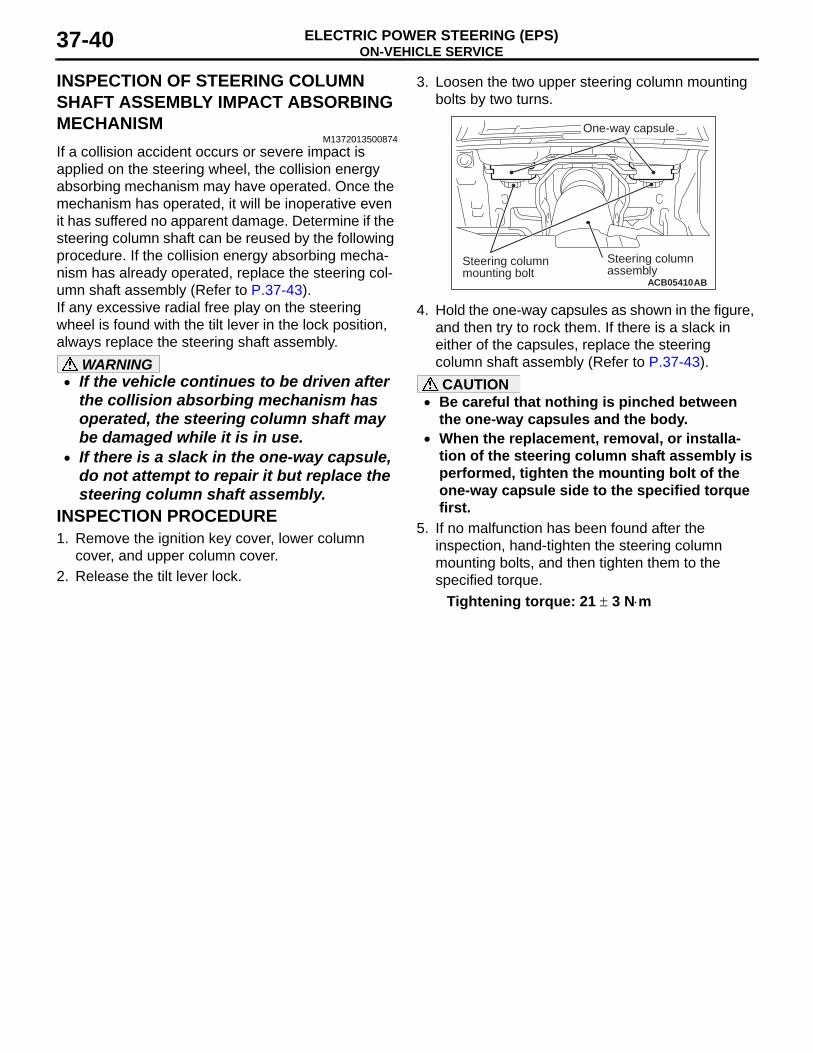
ON-VEHICLE SERVICEELECTRIC POWER STEERING (EPS)37-40
INSPECTION OF STEERING COLUMN SHAFT ASSEMBLY IMPACT ABSORBING MECHANISM
M1372013500874If a collision accident occurs or severe impact is applied on the steering wheel, the collision energy absorbing mechanism may have operated. Once the mechanism has operated, it will be inoperative even it has suffered no apparent damage. Determine if the steering column shaft can be reused by the following procedure. If the collision energy absorbing mecha-nism has already operated, replace the steering col-umn shaft assembly (Refer to P.37-43).If any excessive radial free play on the steering wheel is found with the tilt lever in the lock position, always replace the steering shaft assembly.
WARNING• If the vehicle continues to be driven after
the collision absorbing mechanism has operated, the steering column shaft may be damaged while it is in use.
• If there is a slack in the one-way capsule, do not attempt to repair it but replace the steering column shaft assembly.
INSPECTION PROCEDURE1. Remove the ignition key cover, lower column
cover, and upper column cover.2. Release the tilt lever lock.
3. Loosen the two upper steering column mounting bolts by two turns.
ACB05410AB
Steering column assembly
One-way capsule
Steering column mounting bolt
4. Hold the one-way capsules as shown in the figure, and then try to rock them. If there is a slack in either of the capsules, replace the steering column shaft assembly (Refer to P.37-43).CAUTION
• Be careful that nothing is pinched between the one-way capsules and the body.
• When the replacement, removal, or installa-tion of the steering column shaft assembly is performed, tighten the mounting bolt of the one-way capsule side to the specified torque first.
5. If no malfunction has been found after the inspection, hand-tighten the steering column mounting bolts, and then tighten them to the specified torque.
Tightening torque: 21 ± 3 N⋅m
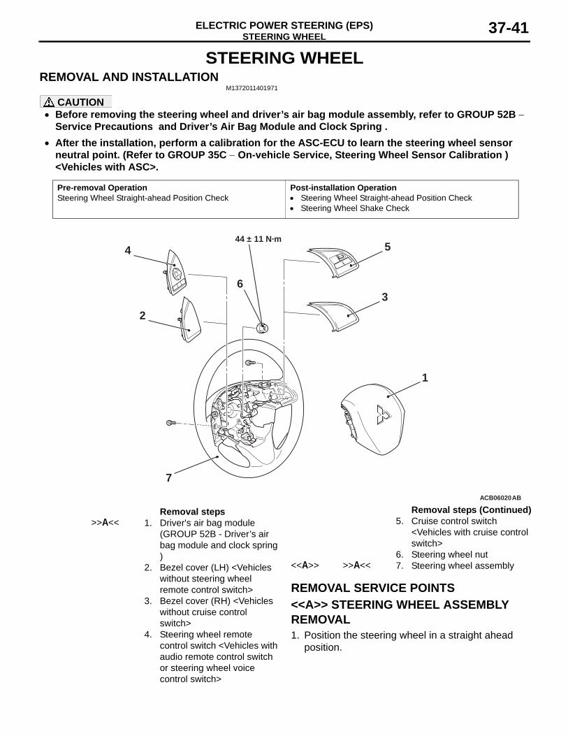
STEERING WHEELELECTRIC POWER STEERING (EPS) 37-41
STEERING WHEELREMOVAL AND INSTALLATION
M1372011401971
CAUTION• Before removing the steering wheel and driver’s air bag module assembly, refer to GROUP 52B −
Service Precautions and Driver’s Air Bag Module and Clock Spring .• After the installation, perform a calibration for the ASC-ECU to learn the steering wheel sensor
neutral point. (Refer to GROUP 35C − On-vehicle Service, Steering Wheel Sensor Calibration ) <Vehicles with ASC>.
Pre-removal OperationSteering Wheel Straight-ahead Position Check
Post-installation Operation• Steering Wheel Straight-ahead Position Check• Steering Wheel Shake Check
ACB06020
1
4
2
7
3
544 ± 11 N·m
6
AB
Removal steps >>A<< 1. Driver's air bag module
(GROUP 52B - Driver’s air bag module and clock spring )
2. Bezel cover (LH) <Vehicles without steering wheel remote control switch>
3. Bezel cover (RH) <Vehicles without cruise control switch>
4. Steering wheel remote control switch <Vehicles with audio remote control switch or steering wheel voice control switch>
5. Cruise control switch <Vehicles with cruise control switch>
6. Steering wheel nut<<A>> >>A<< 7. Steering wheel assembly
REMOVAL SERVICE POINTS<<A>> STEERING WHEEL ASSEMBLY REMOVAL1. Position the steering wheel in a straight ahead
position.
Removal steps (Continued)
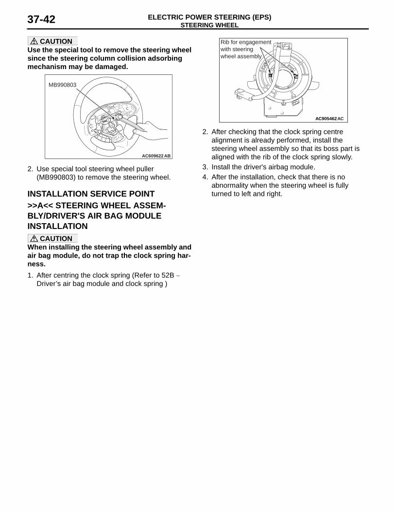
STEERING WHEELELECTRIC POWER STEERING (EPS)37-42
CAUTIONUse the special tool to remove the steering wheel since the steering column collision adsorbing mechanism may be damaged.
AC609622 AB
MB990803
2. Use special tool steering wheel puller (MB990803) to remove the steering wheel.
INSTALLATION SERVICE POINT>>A<< STEERING WHEEL ASSEM-BLY/DRIVER'S AIR BAG MODULE INSTALLATION
CAUTIONWhen installing the steering wheel assembly and air bag module, do not trap the clock spring har-ness.1. After centring the clock spring (Refer to 52B −
Driver’s air bag module and clock spring )
AC905462AC
Rib for engagement with steering wheel assembly
2. After checking that the clock spring centre alignment is already performed, install the steering wheel assembly so that its boss part is aligned with the rib of the clock spring slowly.
3. Install the driver's airbag module.4. After the installation, check that there is no
abnormality when the steering wheel is fully turned to left and right.
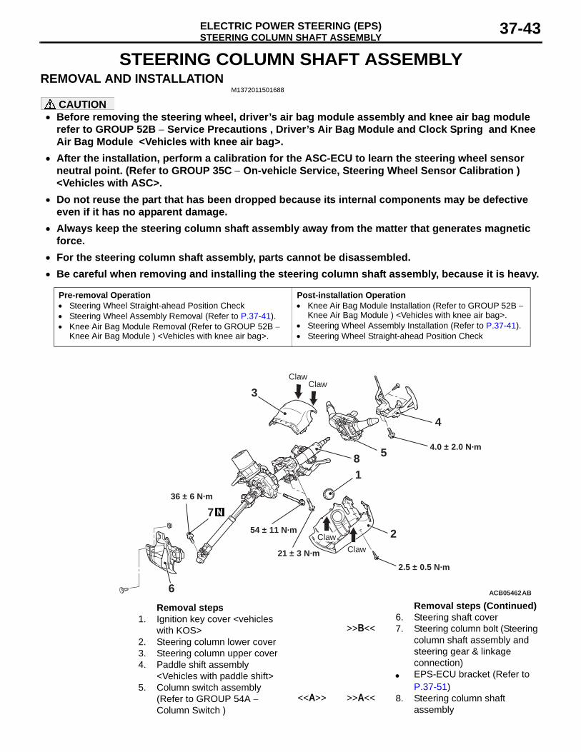
STEERING COLUMN SHAFT ASSEMBLYELECTRIC POWER STEERING (EPS) 37-43
STEERING COLUMN SHAFT ASSEMBLYREMOVAL AND INSTALLATION
M1372011501688
CAUTION• Before removing the steering wheel, driver’s air bag module assembly and knee air bag module
refer to GROUP 52B − Service Precautions , Driver’s Air Bag Module and Clock Spring and Knee Air Bag Module <Vehicles with knee air bag>.
• After the installation, perform a calibration for the ASC-ECU to learn the steering wheel sensor neutral point. (Refer to GROUP 35C − On-vehicle Service, Steering Wheel Sensor Calibration ) <Vehicles with ASC>.
• Do not reuse the part that has been dropped because its internal components may be defective even if it has no apparent damage.
• Always keep the steering column shaft assembly away from the matter that generates magnetic force.
• For the steering column shaft assembly, parts cannot be disassembled.•
Pre-removal Operation• Steering Wheel Straight-ahead Position Check• Steering Wheel Assembly Removal (Refer to P.37-41).• Knee Air Bag Module Removal (Refer to GROUP 52B −
Knee Air Bag Module ) <Vehicles with knee air bag>.
Post-installation Operation• Knee Air Bag Module Installation (Refer to GROUP 52B −
Knee Air Bag Module ) <Vehicles with knee air bag>.• Steering Wheel Assembly Installation (Refer to P.37-41).• Steering Wheel Straight-ahead Position Check
ACB05462AB
4
8
3
2
6
1
7
2.5 ± 0.5 N·m
21 ± 3 N·m
36 ± 6 N·m
5
54 ± 11 N·m
4.0 ± 2.0 N·m
ClawClaw
ClawClaw
Removal steps 1. Ignition key cover <vehicles
with KOS>2. Steering column lower cover3. Steering column upper cover4. Paddle shift assembly
<Vehicles with paddle shift>5. Column switch assembly
(Refer to GROUP 54A − Column Switch )
6. Steering shaft cover>>B<< 7. Steering column bolt (Steering
column shaft assembly and steering gear & linkage connection)
• EPS-ECU bracket (Refer to P.37-51)
<<A>> >>A<< 8. Steering column shaft assembly
Be careful when removing and installing the steering column shaft assembly, because it is heavy.
Removal steps (Continued)
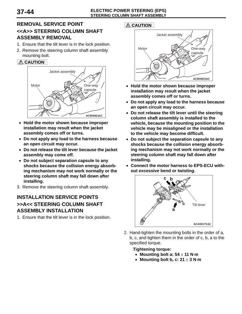
STEERING COLUMN SHAFT ASSEMBLYELECTRIC POWER STEERING (EPS)37-44
REMOVAL SERVICE POINT<<A>> STEERING COLUMN SHAFT ASSEMBLY REMOVAL1. Ensure that the tilt lever is in the lock position.2. Remove the steering column shaft assembly
mounting bolt.
AC904921
Jacket assembly
AC
Motor One-way capsule
CAUTION
• Hold the motor shown because improper installation may result when the jacket assembly comes off or turns.
• Do not apply any load to the harness because an open circuit may occur.
• Do not release the tilt lever because the jacket assembly may come off.
• Do not subject separation capsule to any shocks because the collision energy absorb-ing mechanism may not work normally or the steering column shaft may fall down after installing.
3. Remove the steering column shaft assembly.
INSTALLATION SERVICE POINTS>>A<< STEERING COLUMN SHAFT ASSEMBLY INSTALLATION1. Ensure that the tilt lever is in the lock position.
AC904921
Jacket assembly
AC
Motor One-way capsule
CAUTION
• Hold the motor shown because improper installation may result when the jacket assembly comes off or turns.
• Do not apply any load to the harness because an open circuit may occur.
• Do not release the tilt lever until the steering column shaft assembly is installed to the vehicle, because the mounting position to the vehicle may be misaligned or the installation to the vehicle may become difficult.
• Do not subject the separation capsule to any shocks because the collision energy absorb-ing mechanism may not work normally or the steering column shaft may fall down after installing.
• Connect the motor harness to EPS-ECU with-out excessive bend or twisting.
ACA00173
b
a
c
AC
Tilt lever
2. Hand-tighten the mounting bolts in the order of a, b, c, and tighten them in the order of c, b, a to the specified torque.
Tightening torque:• Mounting bolt a: 54 ± 11 N⋅m• Mounting bolt b, c: 21 ± 3 N⋅m
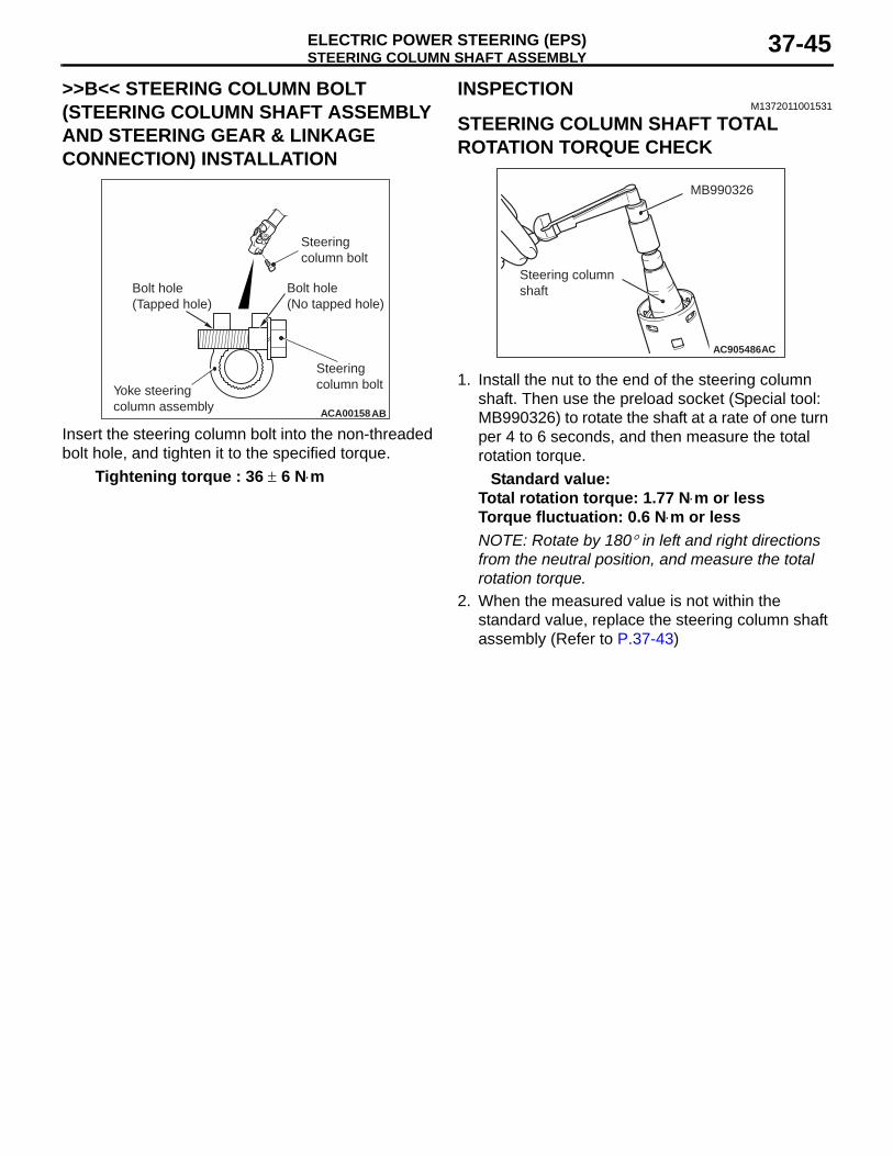
STEERING COLUMN SHAFT ASSEMBLYELECTRIC POWER STEERING (EPS) 37-45
>>B<< STEERING COLUMN BOLT (STEERING COLUMN SHAFT ASSEMBLY AND STEERING GEAR & LINKAGE CONNECTION) INSTALLATION
ACA00158AB
Yoke steering column assembly
Bolt hole(Tapped hole)
Bolt hole(No tapped hole)
Steeringcolumn bolt
Steeringcolumn bolt
Insert the steering column bolt into the non-threaded bolt hole, and tighten it to the specified torque.
Tightening torque : 36 ± 6 N⋅m
INSPECTIONM1372011001531
STEERING COLUMN SHAFT TOTAL ROTATION TORQUE CHECK
AC905486
MB990326
Steering column shaft
AC
1. Install the nut to the end of the steering column shaft. Then use the preload socket (Special tool: MB990326) to rotate the shaft at a rate of one turn per 4 to 6 seconds, and then measure the total rotation torque.
Standard value:Total rotation torque: 1.77 N⋅m or lessTorque fluctuation: 0.6 N⋅m or lessNOTE: Rotate by 180° in left and right directions from the neutral position, and measure the total rotation torque.
2. When the measured value is not within the standard value, replace the steering column shaft assembly (Refer to P.37-43)
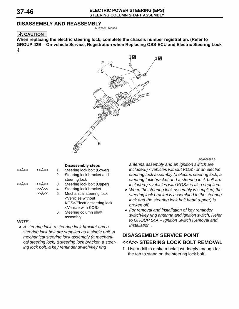
STEERING COLUMN SHAFT ASSEMBLYELECTRIC POWER STEERING (EPS)37-46
DISASSEMBLY AND REASSEMBLYM1372011700634
CAUTIONWhen replacing the electric steering lock, complete the chassis number registration. (Refer to GROUP 42B − On-vehicle Service, Registration when Replacing OSS-ECU and Electric Steering Lock .)
ACA00058AB
N1
4
6
5
N32
Disassembly steps <<A>> >>A<< 1. Steering lock bolt (Lower)
2. Steering lock bracket and steering lock
<<A>> >>A<< 3. Steering lock bolt (Upper)>>A<< 4. Steering lock bracket>>A<< 5. Mechanical steering lock
<Vehicles without KOS>/Electric steering lock <Vehicle with KOS>
6. Steering column shaft assembly
NOTE: .• A steering lock, a steering lock bracket and a
steering lock bolt are supplied as a single unit. A mechanical steering lock assembly (a mechani-cal steering lock, a steering lock bracket, a steer-ing lock bolt, a key reminder switch/key ring
antenna assembly and an ignition switch are included.) <vehicles without KOS> or an electric steering lock assembly (a electric steering lock, a steering lock bracket and a steering lock bolt are included.) <vehicles with KOS> is also supplied.
• When the steering lock assembly is supplied, the steering lock bracket is assembled to the steering lock and the steering lock bolt head (upper) is broken off.
• For removal and installation of key reminder switch/key ring antenna and ignition switch, Refer to GROUP 54A − Ignition Switch Removal and Installation .
DISASSEMBLY SERVICE POINT<<A>> STEERING LOCK BOLT REMOVAL1. Use a drill to make a hole just deeply enough for
the tap to stand on the steering lock bolt.
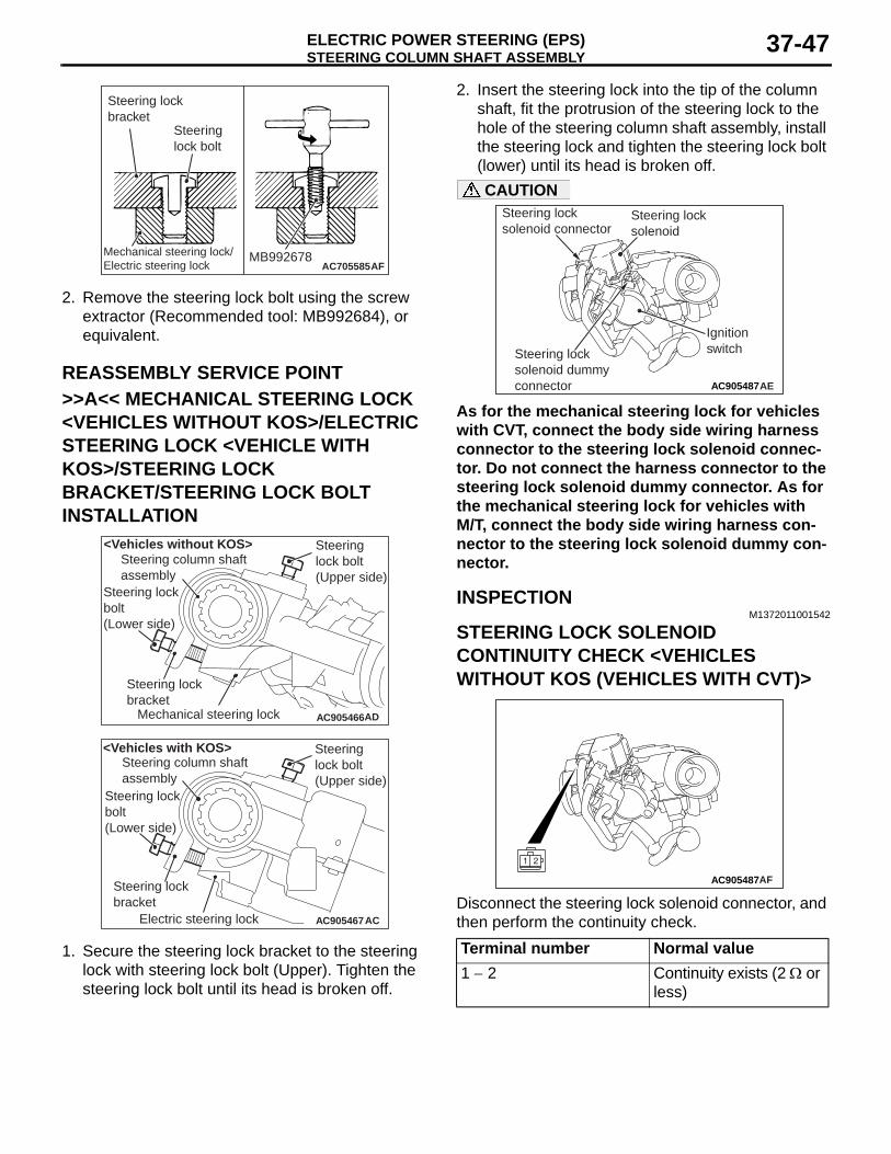
STEERING COLUMN SHAFT ASSEMBLYELECTRIC POWER STEERING (EPS) 37-47
AC705585AFMechanical steering lock/Electric steering lock
MB992678
Steering lockbracket
Steeringlock bolt
2. Remove the steering lock bolt using the screw extractor (Recommended tool: MB992684), or equivalent.
REASSEMBLY SERVICE POINT>>A<< MECHANICAL STEERING LOCK <VEHICLES WITHOUT KOS>/ELECTRIC STEERING LOCK <VEHICLE WITH KOS>/STEERING LOCK BRACKET/STEERING LOCK BOLT INSTALLATION
AC905466AD
Steering column shaft assembly
Steering lock bracket
Mechanical steering lock
Steering lock bolt (Lower side)
Steering lock bolt (Upper side)
<Vehicles without KOS>
AC905467AC
Steering column shaft assembly
Steering lock bracket
Electric steering lock
Steering lock bolt (Lower side)
Steering lock bolt (Upper side)
<Vehicles with KOS>
1. Secure the steering lock bracket to the steering lock with steering lock bolt (Upper). Tighten the steering lock bolt until its head is broken off.
2. Insert the steering lock into the tip of the column shaft, fit the protrusion of the steering lock to the hole of the steering column shaft assembly, install the steering lock and tighten the steering lock bolt (lower) until its head is broken off.
AC905487
Steering lock solenoid
Steering lock solenoid connector
Steering lock solenoid dummy connector
Ignition switch
AE
CAUTION
As for the mechanical steering lock for vehicles with CVT, connect the body side wiring harness connector to the steering lock solenoid connec-tor. Do not connect the harness connector to the steering lock solenoid dummy connector. As for the mechanical steering lock for vehicles with M/T, connect the body side wiring harness con-nector to the steering lock solenoid dummy con-nector.
INSPECTIONM1372011001542
STEERING LOCK SOLENOID CONTINUITY CHECK <VEHICLES WITHOUT KOS (VEHICLES WITH CVT)>
AC905487AF
Disconnect the steering lock solenoid connector, and then perform the continuity check.Terminal number Normal value1 − 2 Continuity exists (2 Ω or
less)
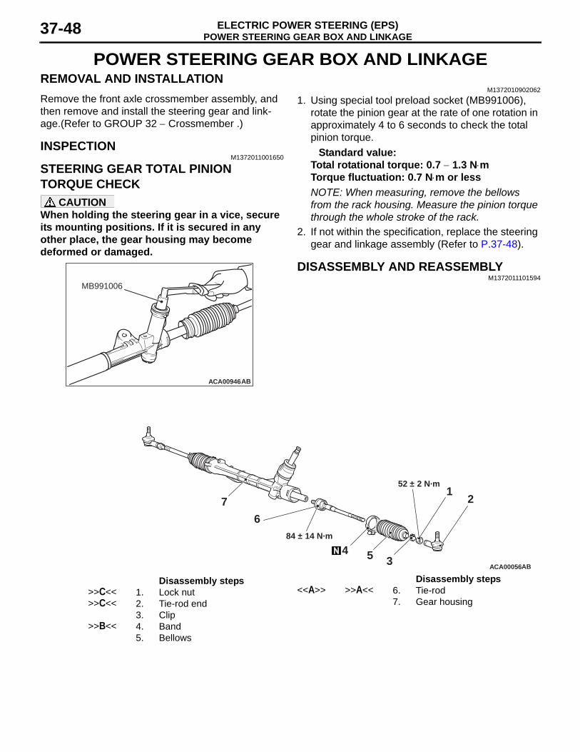
POWER STEERING GEAR BOX AND LINKAGEELECTRIC POWER STEERING (EPS)37-48
POWER STEERING GEAR BOX AND LINKAGEREMOVAL AND INSTALLATION
M1372010902062Remove the front axle crossmember assembly, and then remove and install the steering gear and link-age.(Refer to GROUP 32 − Crossmember .)
INSPECTIONM1372011001650
STEERING GEAR TOTAL PINION TORQUE CHECK
CAUTIONWhen holding the steering gear in a vice, secure its mounting positions. If it is secured in any other place, the gear housing may become deformed or damaged.
ACA00946
MB991006
AB
1. Using special tool preload socket (MB991006), rotate the pinion gear at the rate of one rotation in approximately 4 to 6 seconds to check the total pinion torque.
Standard value:Total rotational torque: 0.7 − 1.3 N⋅mTorque fluctuation: 0.7 N⋅m or lessNOTE: When measuring, remove the bellows from the rack housing. Measure the pinion torque through the whole stroke of the rack.
2. If not within the specification, replace the steering gear and linkage assembly (Refer to P.37-48).
DISASSEMBLY AND REASSEMBLYM1372011101594
ACA00056
84 ± 14 N·m
52 ± 2 N·m
54
6
7
3
12
AB
Disassembly steps >>C<< 1. Lock nut>>C<< 2. Tie-rod end
3. Clip>>B<< 4. Band
5. Bellows
<<A>> >>A<< 6. Tie-rod7. Gear housing
Disassembly steps
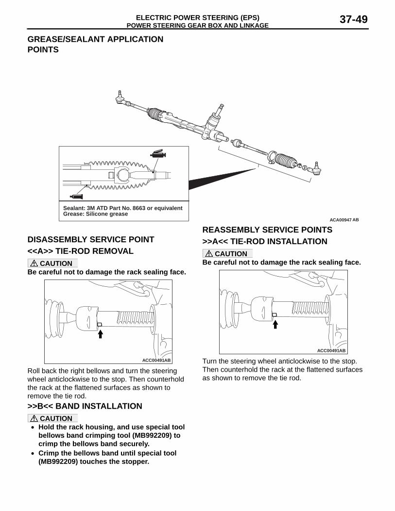
POWER STEERING GEAR BOX AND LINKAGEELECTRIC POWER STEERING (EPS) 37-49
GREASE/SEALANT APPLICATION POINTS
ACA00947 AB
Sealant: 3M ATD Part No. 8663 or equivalentGrease: Silicone grease
DISASSEMBLY SERVICE POINT<<A>> TIE-ROD REMOVAL
CAUTIONBe careful not to damage the rack sealing face.
ACC00491AB
Roll back the right bellows and turn the steering wheel anticlockwise to the stop. Then counterhold the rack at the flattened surfaces as shown to remove the tie rod.
REASSEMBLY SERVICE POINTS>>A<< TIE-ROD INSTALLATION
CAUTIONBe careful not to damage the rack sealing face.
ACC00491AB
Turn the steering wheel anticlockwise to the stop. Then counterhold the rack at the flattened surfaces as shown to remove the tie rod.
>>B<< BAND INSTALLATIONCAUTION
• Hold the rack housing, and use special tool bellows band crimping tool (MB992209) to crimp the bellows band securely.
• Crimp the bellows band until special tool (MB992209) touches the stopper.
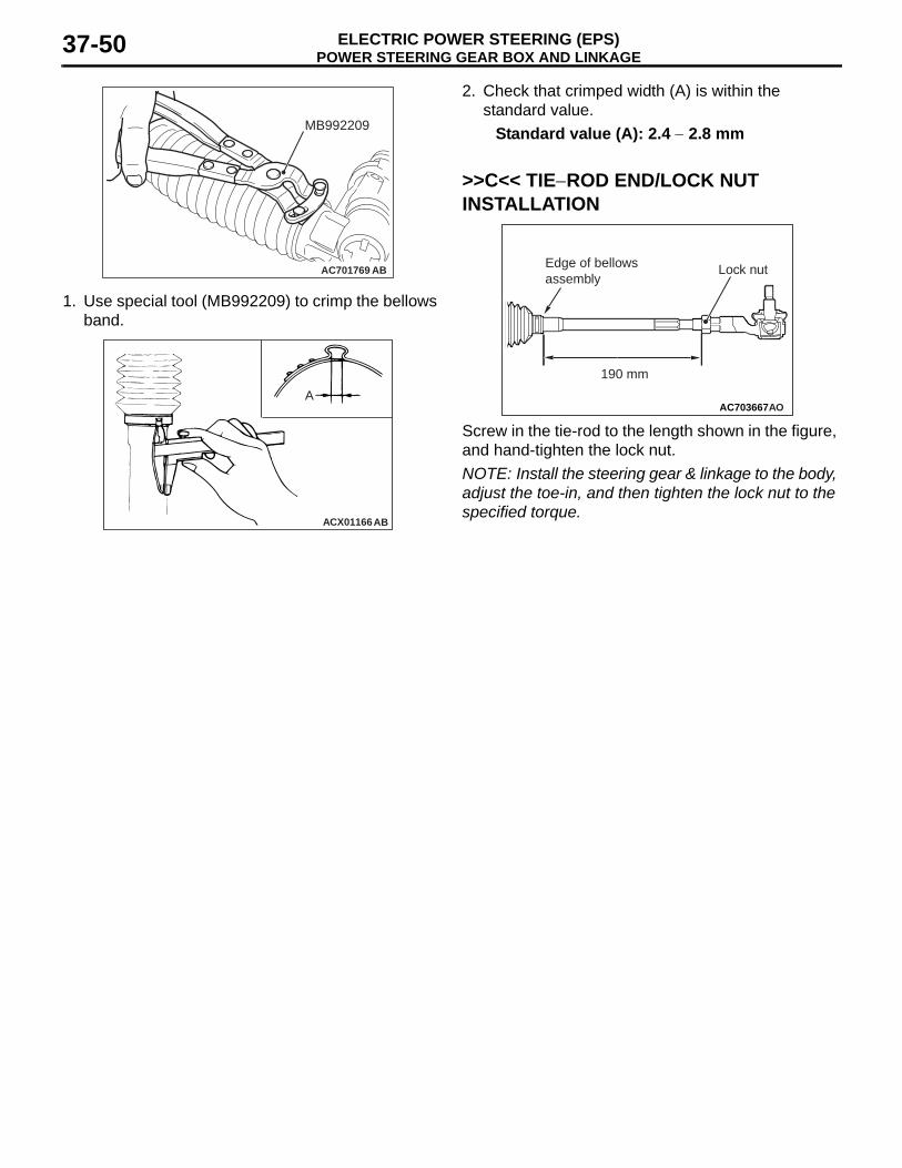
POWER STEERING GEAR BOX AND LINKAGEELECTRIC POWER STEERING (EPS)37-50
AC701769
MB992209
AB
1. Use special tool (MB992209) to crimp the bellows band.
ACX01166AB
A
2. Check that crimped width (A) is within the standard value.
Standard value (A): 2.4 − 2.8 mm
>>C<< TIE−ROD END/LOCK NUT INSTALLATION
AC703667
190 mm
AO
Lock nutEdge of bellowsassembly
Screw in the tie-rod to the length shown in the figure, and hand-tighten the lock nut.NOTE: Install the steering gear & linkage to the body, adjust the toe-in, and then tighten the lock nut to the specified torque.
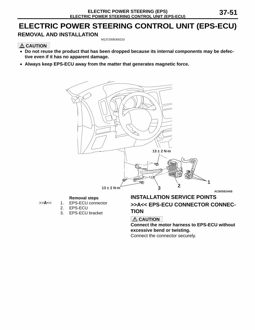
ELECTRIC POWER STEERING CONTROL UNIT (EPS-ECU)ELECTRIC POWER STEERING (EPS) 37-51
ELECTRIC POWER STEERING CONTROL UNIT (EPS-ECU)REMOVAL AND INSTALLATION
M1372006300210
CAUTION• Do not reuse the product that has been dropped because its internal components may be defec-
tive even if it has no apparent damage.•
ACB05824AB
12313 ± 2 N·m
13 ± 2 N·m
Removal steps >>A<< 1. EPS-ECU connector
2. EPS-ECU3. EPS-ECU bracket
Always keep EPS-ECU away from the matter that generates magnetic force.
INSTALLATION SERVICE POINTS>>A<< EPS-ECU CONNECTOR CONNEC-TION
CAUTIONConnect the motor harness to EPS-ECU without excessive bend or twisting.Connect the connector securely.