Embed Size (px)
Citation preview
37-1
GROUP 37
POWER STEERINGCONTENTS
GENERAL INFORMATION . . . . . . . . 37-2
GENERAL SPECIFICATIONS. . . . . . 37-2
SERVICE SPECIFICATIONS. . . . . . . 37-3
LUBRICANTS . . . . . . . . . . . . . . . . . . 37-3
SEALANTS . . . . . . . . . . . . . . . . . . . . 37-3
POWER STEERING DIAGNOSIS . . . 37-4INTRODUCTION TO POWER STEERING DIAGNOSIS . . . . . . . . . . . . . . . . . . . . . . . . 37-4POWER STEERING DIAGNOSIS TROUBLESHOOTING STRATEGY . . . . . . 37-4SYMPTOM CHART. . . . . . . . . . . . . . . . . . . 37-4SYMPTOM PROCEDURES . . . . . . . . . . . . 37-5
SPECIAL TOOLS. . . . . . . . . . . . . . . . 37-12
ON-VEHICLE SERVICE. . . . . . . . . . . 37-14STEERING WHEEL FREE PLAY CHECK . 37-14STEERING ANGLE CHECK. . . . . . . . . . . . 37-14TIE ROD END BALL JOINT DUST COVER CHECK . . . . . . . . . . . . . . . . . . . . . . . . . . . . 37-15TIE ROD END BALL JOINT BREAKAWAY TORQUE CHECK . . . . . . . . . . . . . . . . . . . . 37-15STATIONARY STEERING EFFORT CHECK . . . . . . . . . . . . . . . . . . . . . . . . . . . . 37-16STEERING WHEEL RETURN TO CENTER CHECK . . . . . . . . . . . . . . . . . . . . . . . . . . . . 37-17
DRIVE BELT TENSION CHECK AND ADJUSTMENT . . . . . . . . . . . . . . . . . . . . . . 37-17FLUID LEVEL CHECK . . . . . . . . . . . . . . . . 37-17FLUID REPLACEMENT . . . . . . . . . . . . . . . 37-18POWER STEERING SYSTEM AIR BLEEDING . . . . . . . . . . . . . . . . . . . . . . . . . 37-19OIL PUMP PRESSURE TEST . . . . . . . . . . 37-20POWER STEERING PRESSURE SWITCH CHECK . . . . . . . . . . . . . . . . . . . . . . . . . . . . 37-21
STEERING WHEEL*. . . . . . . . . . . . . . 37-22REMOVAL AND INSTALLATION . . . . . . . . 37-22
STEERING SHAFT* . . . . . . . . . . . . . . 37-26REMOVAL AND INSTALLATION . . . . . . . . 37-26DISASSEMBLY AND REASSEMBLY . . . . . 37-29
POWER STEERING GEAR BOX AND LINKAGE* . . . . . . . . . . . . . . . . . . . . . . 37-31
REMOVAL AND INSTALLATION . . . . . . . . 37-31INSPECTION. . . . . . . . . . . . . . . . . . . . . . . . 37-35DISASSEMBLY AND REASSEMBLY . . . . . 37-36
POWER STEERING OIL PUMP ASSEMBLY. . . . . . . . . . . . . . . . . . . . . 37-38
REMOVAL AND INSTALLATION . . . . . . . . 37-38
POWER STEERING HOSES . . . . . . . 37-40REMOVAL AND INSTALLATION . . . . . . . . 37-40
WARNINGS REGARDING SERVICING OF SUPPLEMENTAL RESTRAINT SYSTEM (SRS) EQUIPPED VEHICLES
WARNING• Improper service or maintenance of any component of the SRS, or any SRS-related component, can lead to
personal injury or death to service personnel (from inadvertent firing of the air bag) or to the driver and passenger (from rendering the SRS inoperative).
• Service or maintenance of any SRS component or SRS-related component must be performed only at an authorized MITSUBISHI dealer.
• MITSUBISHI dealer personnel must thoroughly review this manual, and especially its GROUP 52B - Supplemental Restraint System (SRS) before beginning any service or maintenance of any component of the SRS or any SRS-related component.
NOTEThe SRS includes the following components: SRS air bag control unit, SRS warning light, front impact sensors, driver�s and passenger�s (front) air bag modules, knee air bag module, side-airbag module, curtain air bag module, side impact sensors, seat belt pre-tensioners, clock spring, and interconnecting wiring. Other SRS-related components (that may have to be removed/installed in connection with SRS service or maintenance) are indicated in the table of contents by an asterisk (*).

GENERAL INFORMATIONPOWER STEERING37-2
GENERAL INFORMATIONM1372000101192
• The steering wheel has three spokes. All vehicles are equipped with SRS (Supplemental Restraint System).
• The steering column has a shock absorbing mechanism and a tilt steering mechanism.
•
AC710604AB
Steering wheel
Steering column shaft assembly
Pressure hose assembly
Oil reservoir
Suction hose
Oil pump assembly
Steering gear
Return hose
Front axle crossmember
Heat protector
Pressure switch
Cooler tube assembly
The steering system uses a vane oil pump with a fluid flow control system, so that steering effort varies with engine speed.
GENERAL SPECIFICATIONSM1372000200431
Item SpecificationPower steering gear box Type Rack and pinion
Stroke ratio (Rack stroke/Steering wheel maximum turning radius) mm/rev (in/rev)
65.97 (2.59)
Oil pump Type Vane type
Displacement cm3/rev (cu in/rev) 9.0 (0.55)
Relief set pressure MPa (psi) 8.55 (1.197)
TSB Revision
SERVICE SPECIFICATIONSPOWER STEERING 37-3
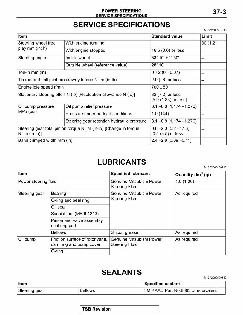
SERVICE SPECIFICATIONSM1372000301390
Item Standard value LimitSteering wheel free play mm (inch)
With engine running − 30 (1.2)
With engine stopped 16.5 (0.6) or less −Steering angle Inside wheel 33° 10' ± 1° 30' −
Outside wheel (reference value) 28° 10' −Toe-in mm (in) 0 ± 2 (0 ± 0.07) −Tie rod end ball joint breakaway torque N⋅ m (in-lb) 2.9 (26) or less −Engine idle speed r/min 700 ± 50 −Stationary steering effort N (lb) [Fluctuation allowance N (lb)] 32 (7.2) or less
[5.9 (1.33) or less]−
Oil pump pressure MPa (psi)
Oil pump relief pressure 8.1 − 8.8 (1,174 − 1,276) −Pressure under no-load conditions 1.0 (144) −Steering gear retention hydraulic pressure 8.1 − 8.8 (1,174 − 1,276) −
Steering gear total pinion torque N⋅ m (in-lb) [Change in torque N⋅ m (in-lb)]
0.6 − 2.0 (5.2 − 17.6)[0.4 (3.5) or less]
−
Band crimped width mm (in) 2.4 − 2.8 (0.09 − 0.11) −
LUBRICANTSM1372000400822
Item Specified lubricant Quantity dm3 (qt)Power steering fluid Genuine Mitsubishi Power
Steering Fluid1.0 (1.06)
Steering gear Bearing Genuine Mitsubishi Power Steering Fluid
As requiredO-ring and seal ringOil sealSpecial tool (MB991213)Pinion and valve assembly seal ring partBellows Silicon grease As required
Oil pump Friction surface of rotor vane, cam ring and pump cover
Genuine Mitsubishi Power Steering Fluid
As required
O-ring
SEALANTSM1372000500852
Item Specified sealantSteering gear Bellows 3M™ AAD Part No.8663 or equivalent
TSB Revision

POWER STEERING DIAGNOSISPOWER STEERING37-4
POWER STEERING DIAGNOSISINTRODUCTION TO POWER STEERING DIAGNOSIS
M1372008500254Hydraulic power steering is used for all vehicles. Faults in the power steering can include excessive play of the steering wheel, difficult steering wheel operation, noise, vibration, and oil leaks, etc. Possi-ble causes of these faults can include defects in the gear box, oil pump or steering linkage.
POWER STEERING DIAGNOSIS TROUBLESHOOTING STRATEGYM1372007300291
Use these steps to plan your diagnostic strategy. If you follow them carefully, you will be sure that you have exhausted most of the possible ways to find a power steering fault.1. Gather information from the customer.
2. Verify that the condition described by the customer exists.
3. Find the malfunction by following the Symptom Chart.
4. Verify malfunction is eliminated.
SYMPTOM CHARTM1372007600366
Symptom Inspection procedure
Reference page
Excessive play of steering wheel 1 P.37-5Difficult steering wheel operation (insufficient power assist) 2 P.37-6Rattling noise 3 P.37-7Shrill noise 4 P.37-8Squealing noise 5 P.37-8Hissing noise 6 P.37-8Droning noise 7 P.37-9Squeaking noise 8 P.37-9Vibration 9 P.37-10Oil leakage from hose connection 10 P.37-10Oil leakage from hose assembly 11 P.37-11Oil leakage from oil reservoir 12 P.37-11Oil leakage from oil pump 13 P.37-11Oil leakage from steering gear 14 P.37-12
TSB Revision

POWER STEERING DIAGNOSISPOWER STEERING 37-5
SYMPTOM PROCEDURES
INSPECTION PROCEDURE 1: Excessive Play of Steering Wheel
DIAGNOSIS
STEP 1. Check for looseness at the steering shaft coupling section and at the steering wheel linkage.Q: Is there any looseness?
YES : Repair or replace the part. Then go to Step 3.NO : Go to Step 2.
STEP 2. Check the steering wheel free play.(1) With the engine running (hydraulic operation), set the front
wheels straight ahead.
AC609390AB
(2) Measure the play on the steering wheel circumference before the wheels start to move when slightly moving the steering wheel in both directions.
Limit: 30 mm (1.2 inch)(3) If the free play exceeds the limit value, set the steering
wheel straight ahead with the engine stopped. Load approximately 5 N (1.1 pound) towards the steering circumference and check the play.
Standard value (steering wheel play with engine stopped): 16.5 mm (0.6 inch) or less
Q: Does the play exceed the standard value?YES : Remove the steering gear box (Refer to P.37-31) and
check the total pinion torque (Refer to P.37-31). Then go to Step 3.
NO : Go to Step 3.
STEP 3. Check the steering wheel play.Verify that the steering wheel play is not excessive.Q: Is the steering wheel play excessive?
YES : Repeat from Step 1.NO : The procedure is complete.
TSB Revision

POWER STEERING DIAGNOSISPOWER STEERING37-6
INSPECTION PROCEDURE 2: Difficult Steering Wheel Operation (Insufficient Power Assist)
DIAGNOSIS
STEP 1. Check the power steering oil pump drive belt tension.Refer to GROUP 00, Maintenance Service − Drive Belts P.00-66.Q: Is the power steering oil pump drive belt tension within
the standard value?YES : Go to Step 2.NO : Adjust the tension (Refer to GROUP 00, Maintenance
Service − Drive Belts P.00-66). Then go to Step 10.
STEP 2. Check the drive belt for damage.Q: Is the drive belt damaged?
YES : Replace the drive belt. Then go to Step 10.NO : Go to Step 3.
STEP 3. Check the fluid level.(1) Park the vehicle on a flat, level surface, and then start the
engine.(2) Turn the steering wheel several times to raise the
temperature of the fluid to approximately 50 − 60° C (122 − 140° F).
(3) With the engine running, turn the wheel all the way to the left and right several times.
AC608306With engine stopped
AC
Fluid level change: Within 5 mm (0.2 in)
With engine running
(4) Check the fluid in the oil reservoir for foaming or milkiness. Check the difference of the fluid level when the engine is stopped, and while it is running. If the change of the fluid level is 5 mm (0.2 inch) or more, bleed the air from the system (Refer to P.37-19).
Q: Is the fluid foamy?YES : Go to Step 4.NO : Go to Step 10.
STEP 4. Check for entry of air.Q: Has air entered?
YES : Bleed the air (Refer to P.37-19). Then go to Step 10 .NO : Go to Step 5.
STEP 5. Check each hose for crushing or twisting.Q: Is any hose crushed or twisted?
YES : Repair or replace the hose. Then go to Step 10.NO : Go to Step 6.
TSB Revision
POWER STEERING DIAGNOSISPOWER STEERING 37-7
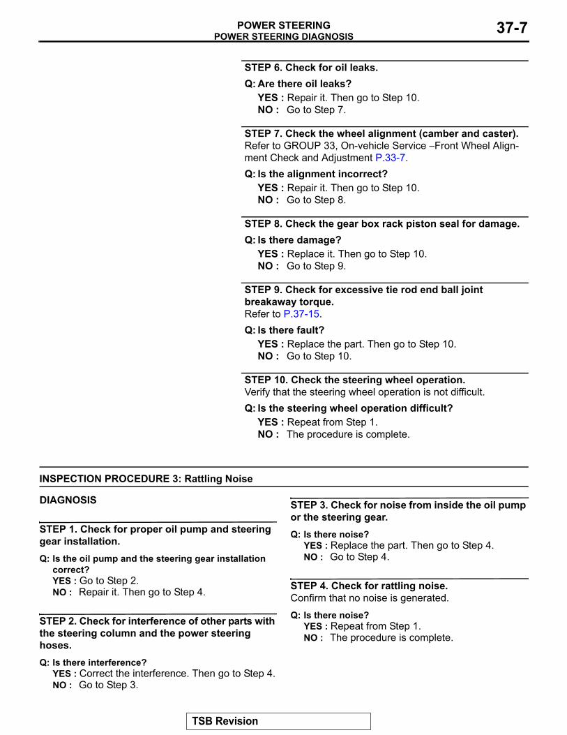
STEP 6. Check for oil leaks.Q: Are there oil leaks?
YES : Repair it. Then go to Step 10.NO : Go to Step 7.
STEP 7. Check the wheel alignment (camber and caster).Refer to GROUP 33, On-vehicle Service − Front Wheel Align-ment Check and Adjustment P.33-7.Q: Is the alignment incorrect?
YES : Repair it. Then go to Step 10.NO : Go to Step 8.
STEP 8. Check the gear box rack piston seal for damage.Q: Is there damage?
YES : Replace it. Then go to Step 10.NO : Go to Step 9.
STEP 9. Check for excessive tie rod end ball joint breakaway torque.Refer to P.37-15.Q: Is there fault?
YES : Replace the part. Then go to Step 10.NO : Go to Step 10.
STEP 10. Check the steering wheel operation.Verify that the steering wheel operation is not difficult.Q: Is the steering wheel operation difficult?
YES : Repeat from Step 1.NO : The procedure is complete.
INSPECTION PROCEDURE 3: Rattling Noise
DIAGNOSIS
STEP 1. Check for proper oil pump and steering gear installation.Q: Is the oil pump and the steering gear installation
correct?YES : Go to Step 2.NO : Repair it. Then go to Step 4.
STEP 2. Check for interference of other parts with the steering column and the power steering hoses.Q: Is there interference?
YES : Correct the interference. Then go to Step 4.NO : Go to Step 3.
STEP 3. Check for noise from inside the oil pump or the steering gear.Q: Is there noise?
YES : Replace the part. Then go to Step 4.NO : Go to Step 4.
STEP 4. Check for rattling noise.Confirm that no noise is generated.
Q: Is there noise?YES : Repeat from Step 1. NO : The procedure is complete.
TSB Revision
POWER STEERING DIAGNOSISPOWER STEERING37-8
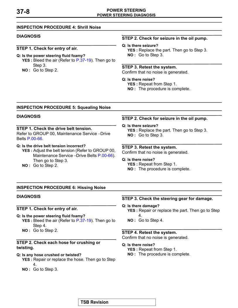
INSPECTION PROCEDURE 4: Shrill Noise
DIAGNOSIS
STEP 1. Check for entry of air.Q: Is the power steering fluid foamy?
YES : Bleed the air (Refer to P.37-19). Then go to Step 3.
NO : Go to Step 2.
STEP 2. Check for seizure in the oil pump.Q: Is there seizure?
YES : Replace the part. Then go to Step 3.NO : Go to Step 3.
STEP 3. Retest the system.Confirm that no noise is generated.
Q: Is there noise?YES : Repeat from Step 1.NO : The procedure is complete.
INSPECTION PROCEDURE 5: Squealing Noise
DIAGNOSIS
STEP 1. Check the drive belt tension.Refer to GROUP 00, Maintenance Service − Drive Belts P.00-66.
Q: Is the drive belt tension incorrect?YES : Adjust the belt tension (Refer to GROUP 00,
Maintenance Service − Drive Belts P.00-66). Then go to Step 3.
NO : Go to Step 2.
STEP 2. Check for seizure in the oil pump.Q: Is there seizure?
YES : Replace the part. Then go to Step 3.NO : Go to Step 3.
STEP 3. Retest the system.Confirm that no noise is generated.
Q: Is there noise?YES : Repeat from Step 1.NO : The procedure is complete.
INSPECTION PROCEDURE 6: Hissing Noise
DIAGNOSIS
STEP 1. Check for entry of air.Q: Is the power steering fluid foamy?
YES : Bleed the air (Refer to P.37-19). Then go to Step 4.
NO : Go to Step 2.
STEP 2. Check each hose for crushing or twisting.Q: Is any hose crushed or twisted?
YES : Repair or replace the hose. Then go to Step 4.
NO : Go to Step 3.
STEP 3. Check the steering gear for damage.Q: Is there damage?
YES : Repair or replace the part. Then go to Step 4.
NO : Go to Step 4.
STEP 4. Retest the system.Confirm that no noise is generated.
Q: Is there noise?YES : Repeat from Step 1.NO : The procedure is complete.
TSB Revision

POWER STEERING DIAGNOSISPOWER STEERING 37-9
INSPECTION PROCEDURE 7: Droning Noise
DIAGNOSIS
STEP 1. Check the oil pump or oil pump bracket installation.Q: Is the oil pump or the oil pump bracket installation
correct?YES : Go to Step 2.NO : Repair it. Then go to Step 3.
STEP 2. Check the oil pump for damage.NOTE: If a slight "beat noise" is produced by the oil pump when the steering wheel is turned fully and held in that position, this is not a malfunction.
Q: Is there damage?YES : Replace the oil pump. Then go to Step 3.NO : Go to Step 3.
STEP 3. Retest the system.Confirm that no noise is generated.
Q: Is there noise?YES : Repeat from Step 1.NO : The procedure is complete.
INSPECTION PROCEDURE 8: Squeaking Noise
DIAGNOSIS
STEP 1. Check for interference of the wheel and the vehicle body.If interfering, adjust the steering angle.
AC000756AB
(1) Place the front wheel on a turning radius gauge and measure the steering angle.
Standard value:
Item SpecificationInside wheel 33° 10' ± 1° 30'
Outside wheel (reference value)
28° 10'
(2) If the steering angle is not within the standard value, adjust the toe-in.
Standard value: 0 ± 2 mm (0 ± 0.07 inch)
AC705438AB
Clip
Lock nut
(3) Adjust the toe-in by undoing the clip and jam nut, and turning the left and right tie rod turnbuckles by the same amount (in opposite directions).NOTE: The toe will move out as the left turnbuckle is turned toward the front of the vehicle and the right turnbuckle is turned toward the rear of the vehicle.
Q: Is the steering angle normal?YES : Go to Step 2.NO : Adjust the steering angle. Then go to Step 3.
TSB Revision
POWER STEERING DIAGNOSISPOWER STEERING37-10
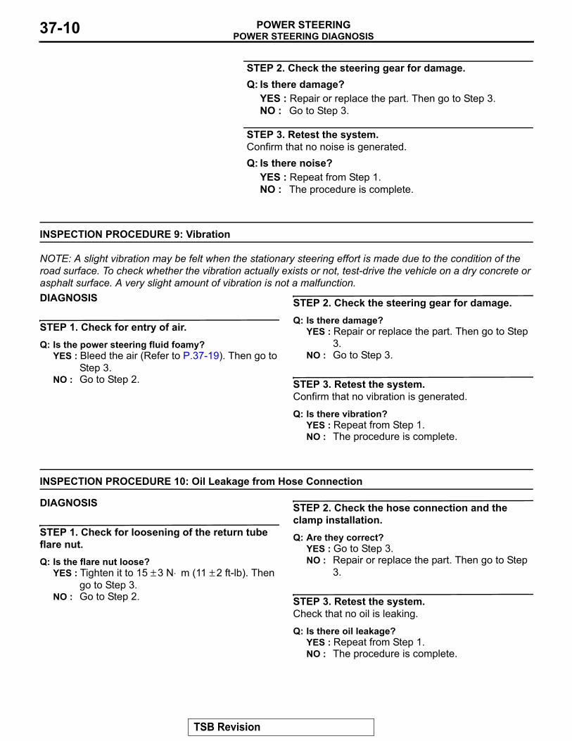
STEP 2. Check the steering gear for damage.Q: Is there damage?
YES : Repair or replace the part. Then go to Step 3.NO : Go to Step 3.
STEP 3. Retest the system.Confirm that no noise is generated.Q: Is there noise?
YES : Repeat from Step 1.NO : The procedure is complete.
INSPECTION PROCEDURE 9: Vibration
NOTE: A slight vibration may be felt when the stationary steering effort is made due to the condition of the road surface. To check whether the vibration actually exists or not, test-drive the vehicle on a dry concrete or asphalt surface. A very slight amount of vibration is not a malfunction.DIAGNOSIS
STEP 1. Check for entry of air.Q: Is the power steering fluid foamy?
YES : Bleed the air (Refer to P.37-19). Then go to Step 3.
NO : Go to Step 2.
STEP 2. Check the steering gear for damage.Q: Is there damage?
YES : Repair or replace the part. Then go to Step 3.
NO : Go to Step 3.
STEP 3. Retest the system.Confirm that no vibration is generated.
Q: Is there vibration?YES : Repeat from Step 1.NO : The procedure is complete.
INSPECTION PROCEDURE 10: Oil Leakage from Hose Connection
DIAGNOSIS
STEP 1. Check for loosening of the return tube flare nut.Q: Is the flare nut loose?
YES : Tighten it to 15 ± 3 N⋅ m (11 ± 2 ft-lb). Then go to Step 3.
NO : Go to Step 2.
STEP 2. Check the hose connection and the clamp installation.Q: Are they correct?
YES : Go to Step 3.NO : Repair or replace the part. Then go to Step
3.
STEP 3. Retest the system.Check that no oil is leaking.
Q: Is there oil leakage?YES : Repeat from Step 1.NO : The procedure is complete.
TSB Revision

POWER STEERING DIAGNOSISPOWER STEERING 37-11
INSPECTION PROCEDURE 11: Oil Leakage from Hose Assembly
DIAGNOSIS
STEP 1. Check the hose for damage or clogging.Q: Is the hose damaged or clogged?
YES : Repair or replace it. Then go to Step 2.NO : Go to Step 2.
STEP 2. Retest the system.Check that no oil is leaking.
Q: Is there oil leakage?YES : Repeat from Step 1.NO : The procedure is complete.
INSPECTION PROCEDURE 12: Oil Leakage from Oil Reservoir
DIAGNOSIS
STEP 1. Check the oil reservoir for damage.Q: Is there damage?
YES : Repair or replace it. Then go to Step 3.NO : Go to Step 2.
STEP 2. Check for overflowing.Q: Is there oil overflowing from the reservoir?
YES : Adjust fluid level. Then go to Step 3.NO : Go to Step 3.
STEP 3. Retest the system.Q: Is there oil leakage?
YES : Repeat from to Step 1.NO : The procedure is complete.
INSPECTION PROCEDURE 13: Oil Leakage from Oil Pump
DIAGNOSIS
STEP 1. Check the oil pump body for damage.Q: Is there damage?
YES : Replace the part. Then go to Step 3.NO : Go to Step 2.
STEP 2. Check the O-ring or oil seal for damage.Q: Is there damage?
YES : Replace the part. Then go to Step 3.NO : Go to Step 3.
STEP 3. Retest the system.Check that no oil is leaking.
Q: Is there oil leakage?YES : Repeat from Step 1.NO : The procedure is complete.
TSB Revision

SPECIAL TOOLSPOWER STEERING37-12
INSPECTION PROCEDURE 14: Oil Leakage from Steering Gear
DIAGNOSIS
STEP 1. Check the steering gear housing for damage.Q: Is there damage?
YES : Replace the part. Then go to Step 3.NO : Go to Step 2.
STEP 2. Check the oil-ring or oil seal for damage.Q: Is there damage?
YES : Replace the part. Then go to Step 3.NO : Go to Step 3.
STEP 3. Retest the system.Check that no oil is leaking.
Q: Is there oil leakage?YES : Repeat from Step 1.NO : The procedure is complete.
SPECIAL TOOLSM1372000601175
Tool Tool number and name
Supersession Application
AC106827
MB991897 or MB992011Ball joint remover
MB991113-01, MB990635-01 or General service tool
Knuckle and tie rod end ball joint disconnectionNOTE: Steering linkage puller (MB990635 or MB991113) is also available to disconnect knuckle and tie rod end ball joint.
MB990326
MB990326Preload socket
General service tool
Tie rod end ball joint breakaway torque check
MB991548
MB991548Power steering oil pressure gauge adapter (Pump side)
MB991548-01 Oil pump pressure test
MB991549
MB991549Power steering oil pressure gauge adapter (Hose side)
MB991549-01
MB990662
MB990662Power steering oil pressure gauge
MB990662-01
TSB Revision
SPECIAL TOOLSPOWER STEERING 37-13
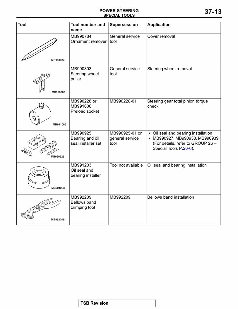
MB990784
MB990784Ornament remover
General service tool
Cover removal
MB990803
MB990803Steering wheel puller
General service tool
Steering wheel removal
MB991006
MB990228 or MB991006Preload socket
MB990228-01 Steering gear total pinion torque check
MB990925
MB990925Bearing and oil seal installer set
MB990925-01 or general service tool
• Oil seal and bearing installation• MB990927, MB990938, MB990939
(For details, refer to GROUP 26 − Special Tools P.26-6).
MB991203
MB991203Oil seal and bearing installer
Tool not available Oil seal and bearing installation
MB992209
MB992209Bellows band crimping tool
MB992209 Bellows band installation
Tool Tool number and name
Supersession Application
TSB Revision

ON-VEHICLE SERVICEPOWER STEERING37-14
ON-VEHICLE SERVICESTEERING WHEEL FREE PLAY CHECK
M1372001000850
1. With the engine running (hydraulic pressure applied), position the front wheel in the straight ahead position.
AC609390AB
2. Measure the side to side steering wheel play until the front wheels actually start moving while turning the steering wheel slightly in the left and right directions.
Limit: 30 mm (1.2 inch)3. If the steering wheel play exceeds the limit value, check the
steering shaft joint or steering linkage for looseness, and replace or repair the faulty components if necessary.
4. If the steering wheel play still exceeds the limit value after Step 3 is performed, position the steering wheel in the straight ahead position, and then apply the force (approximately 5 N) in the circumferential direction.
Standard value (steering wheel play with the engine stopped): 16.5 mm (0.6 inch) or less
5. If the steering wheel play is outside the standard value after Step 4 is performed, remove the steering gear and linkage, and check and adjust the pinion total rotation torque. (Refer to P.37-31).
STEERING ANGLE CHECKM1372001101225
CAUTIONAfter adjusting the steering angle, perform calibration to make the ASC-ECU learn the neutral position of the steer-ing wheel sensor. (Refer to GROUP 35C − On-vehicle Ser-vice, Steering Wheel Sensor Calibration P.35C-267.)1. Check that the wheel alignment is normal. (Refer to GROUP
33 − On-vehicle Service, Wheel Alignment Check and Adjustment (Refer to P.33-7.)
AC000756AB
2. Place the front wheel onto the turning radius gauge, and measure the steering angle.
Standard value:
Item SpecificationsInside wheel 33° 10' ± 1° 30'
Outside wheel (reference value) 28° 10'
TSB Revision
ON-VEHICLE SERVICEPOWER STEERING 37-15
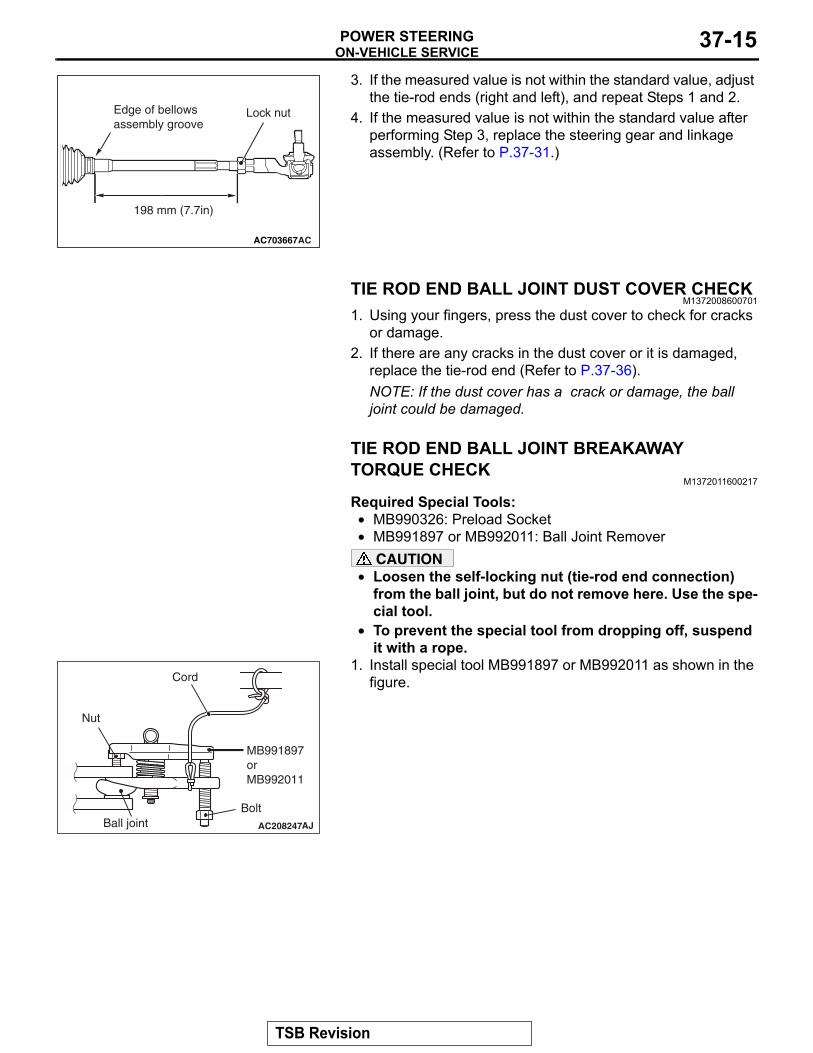
AC703667
198 mm (7.7in)
AC
Lock nutEdge of bellowsassembly groove
3. If the measured value is not within the standard value, adjust the tie-rod ends (right and left), and repeat Steps 1 and 2.
4. If the measured value is not within the standard value after performing Step 3, replace the steering gear and linkage assembly. (Refer to P.37-31.)
TIE ROD END BALL JOINT DUST COVER CHECKM1372008600701
1. Using your fingers, press the dust cover to check for cracks or damage.
2. If there are any cracks in the dust cover or it is damaged, replace the tie-rod end (Refer to P.37-36).NOTE: If the dust cover has a crack or damage, the ball joint could be damaged.
TIE ROD END BALL JOINT BREAKAWAY TORQUE CHECK
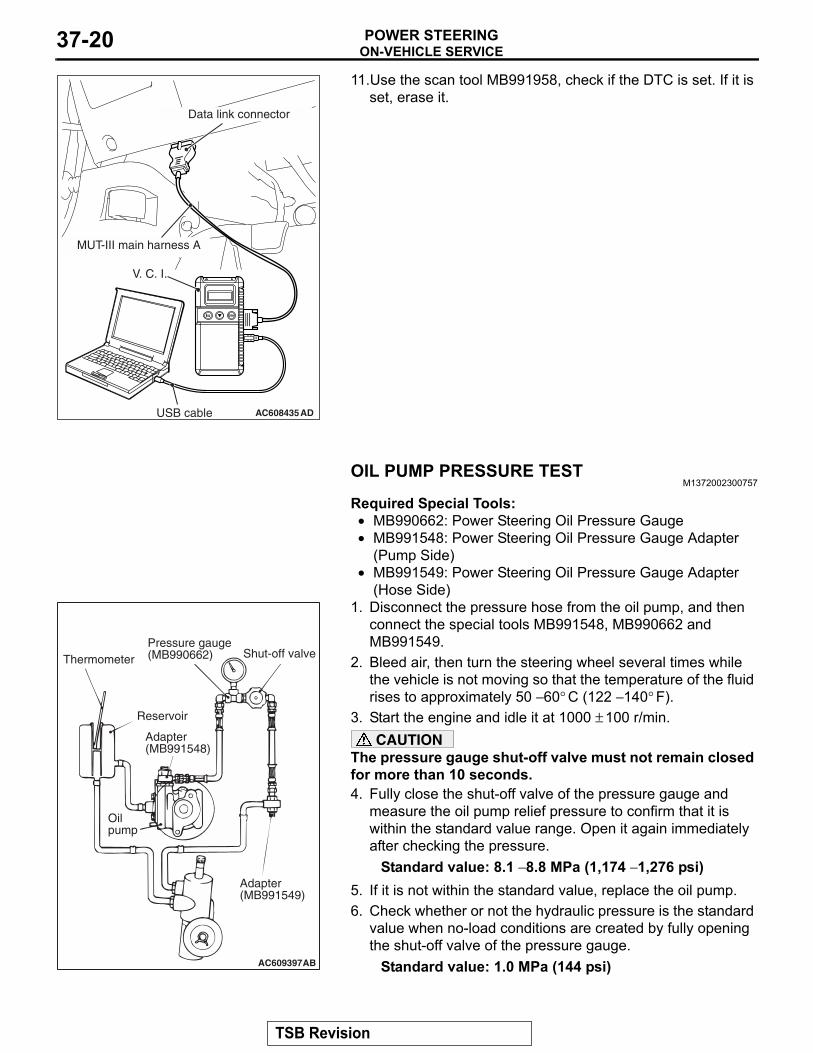
M1372011600217
Required Special Tools:• MB990326: Preload Socket• MB991897 or MB992011: Ball Joint Remover
CAUTION• Loosen the self-locking nut (tie-rod end connection)
from the ball joint, but do not remove here. Use the spe-cial tool.
•
AC208247AJ
Cord
Bolt
MB991897orMB992011
Nut
Ball joint
To prevent the special tool from dropping off, suspend it with a rope.
1. Install special tool MB991897 or MB992011 as shown in the figure.
TSB Revision

ON-VEHICLE SERVICEPOWER STEERING37-16
AC104739AB
Parallel
Knob
Bolt
Correct
Wrong
2. Turn the bolt and knob to make the special tool jaws parallel, then hand-tighten the bolt. After tightening, check that the jaws are still parallel.NOTE: To adjust the special tool jaws to be parallel, set the orientation of the knob as shown in the figure.
3. Unscrew the bolt to disconnect the ball joint.
ACX01129 AB
MB9903264. Move the ball joint stud several times and install the nut on
the stud. Using the special tool MB990326, measure the ball joint breakaway torque.
Standard value: 2.9 N⋅ m (26 in-lb) or less5. If the breakaway torque exceeds the standard value, replace
the tie rod end.6. If the breakaway torque is under the standard value, check
the ball joint for end play or ratcheting. If no end play or ratcheting, the ball joint can be re-used.CAUTION
Always use a new ball joint nut as it is a self-locking nut.7. Install the tie rod end to the knuckle, then tighten a new
self-locking nut to the specified torque.Tightening torque: 40 ± 8 N⋅ m (30 ± 5 ft-lb)
STATIONARY STEERING EFFORT CHECKM1372001700945
1. Park the vehicle on a level paved road, position the steering wheel in the straight ahead position.
2. Start the engine, and maintain the engine speed at 1000 ± 100 r/min.
AC609390AB
3. Position the spring scale on the circumference of the steering wheel, and measure the steering force at the time when the steering wheel is turned to right or left side (within the range of one and a half turns) from the center position.
Standard value:Steering force: 32 N (7.2 lb) or lessFluctuation band: 5.9 N (1.33 lb) or less
4. If not within the standard value, check and adjust the suspected components.
TSB Revision

ON-VEHICLE SERVICEPOWER STEERING 37-17
STEERING WHEEL RETURN TO CENTER CHECKM1372001800715
Conduct a road test:1. Make both gradual and sudden turns and check the steering
wheel return.
AC000989AC
70˚ ormore
70˚ ormore
2. At a vehicle speed of approximately 35 km/h (22 mph), turn the steering wheel 90 degrees, hold a few seconds, then release. If the steering wheel then returns 70 degrees or more, the return can be judged satisfactory.NOTE: There will be a momentary feeling or "heaviness" when the wheel is turned quickly, but this is not abnormal (Oil pump discharge amount is especially apt to be insuffi-cient during idling).
DRIVE BELT TENSION CHECK AND ADJUSTMENT
M1372001900864Refer to GROUP 11A − Engine Adjustment, and Drive Belt Ten-sion Check and Adjustment P.11A-8.)
FLUID LEVEL CHECKM1372002000648
1. Park the vehicle on a flat, level surface.2. Start the engine, and then turn the steering wheel several
times to raise the temperature of the fluid to approximately 50 − 60° C (122 − 140° F).
3. With the engine running, turn the wheel all the way to the left and right several times.
AC608306With engine stopped
AC
Fluid level change: Within 5 mm (0.2 in)
With engine running
4. Check the fluid in the oil reservoir for foaming or milkiness. Check the difference of the fluid level when the engine is stopped, and while it is running. If the change of the fluid level is 5 mm (0.2 inch) or more, air bleeding should be done (Refer to P.37-19).
TSB Revision

ON-VEHICLE SERVICEPOWER STEERING37-18
FLUID REPLACEMENTM1372002100902
1. Raise and support the front wheels.
AC507662AB
Return hose
2. Disconnect the return hose connection, and then connect a vinyl hose to the return hose, and drain the fluid into a container.
AC705444 ABCrank angle sensor
Oil filter
3. Disconnect the crank angle sensor connector.4. While operating the starter motor intermittently, turn the
steering wheel all the way to the left and right several times to drain all of the fluid.
5. Connect the return hose securely, and then secure with the clip.
6. Fill the oil reservoir with GENUINE MITSUBISHI POWER STEERING FLUID to the lower position of the filler, and then bleed the air (Refer to P.37-19).
7. Install the crankshaft position sensor.
AC608435AD
MUT-III main harness A
V. C. I.
USB cable
Data link connector
8. Use the scan tool MB991958, check if the DTC is set. If it is set, erase it.
TSB Revision

ON-VEHICLE SERVICEPOWER STEERING 37-19
POWER STEERING SYSTEM AIR BLEEDINGM1372002200909
Perform air bleeding procedure as necessary after replacing the steering gear or the steering fluid lines.1. Raise and support the front wheels.
AC705444 ABCrank angle sensor
Oil filter
2. Disconnect the crank angle sensor connector.CAUTION
Perform air bleeding only while cranking the engine. If air bleeding is performed while the engine is running, air could enter the fluid. During air bleeding, refill the steering fluid supply so that the level never falls below the lower mark on the dipstick.3. Turn the steering wheel all the way to the left and right five
or six times while using the starter motor to crank the engine intermittently several times (for 15 to 20 seconds).
4. Connect the crank angle sensor connector.5. Start the engine (idling).6. Turn the steering wheel to the left and right until there are no
air bubbles in the oil reservoir.7. Confirm that the fluid is not milky, and that the level is
between the high and low dipstick marks.8. Confirm that there is very little change in the fluid level when
the steering wheel is turned left and right.CAUTION
If the fluid level rises suddenly after the engine is stopped, the air has not been completely bled. If air bleeding is not complete, there will be abnormal noises from the pump and the flow-control valve, and this condition could cause reduce the life of the power steering components.
AC608306With engine stopped
AC
Fluid level change: Within 5 mm (0.2 in)
With engine running
9. Confirm that the change in the fluid level is no more than 5 mm (0.2 inch) when the engine is stopped and when it is running.
10.If the change of the fluid level is 5 mm (0.2 inch) or more, the air has not been completely bled from the system. The air bleeding procedure must be repeated.
TSB Revision
ON-VEHICLE SERVICEPOWER STEERING37-20
AC608435AD
MUT-III main harness A
V. C. I.
USB cable
Data link connector
11.Use the scan tool MB991958, check if the DTC is set. If it is set, erase it.
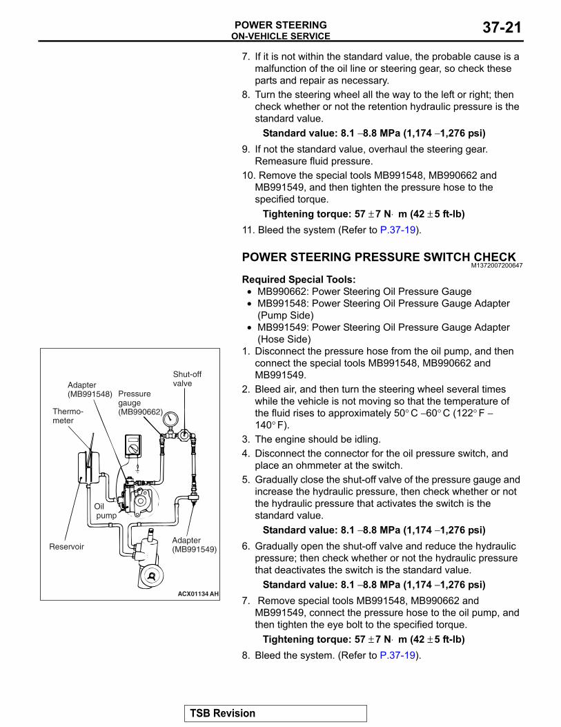
OIL PUMP PRESSURE TESTM1372002300757
Required Special Tools:• MB990662: Power Steering Oil Pressure Gauge• MB991548: Power Steering Oil Pressure Gauge Adapter
(Pump Side)•
AC609397AB
Thermometer
Reservoir
Pressure gauge(MB990662) Shut-off valve
Adapter(MB991548)
Oilpump
Adapter(MB991549)
MB991549: Power Steering Oil Pressure Gauge Adapter (Hose Side)
1. Disconnect the pressure hose from the oil pump, and then connect the special tools MB991548, MB990662 and MB991549.
2. Bleed air, then turn the steering wheel several times while the vehicle is not moving so that the temperature of the fluid rises to approximately 50 − 60° C (122 − 140° F).
3. Start the engine and idle it at 1000 ± 100 r/min.CAUTION
The pressure gauge shut-off valve must not remain closed for more than 10 seconds.4. Fully close the shut-off valve of the pressure gauge and
measure the oil pump relief pressure to confirm that it is within the standard value range. Open it again immediately after checking the pressure.
Standard value: 8.1 − 8.8 MPa (1,174 − 1,276 psi)5. If it is not within the standard value, replace the oil pump.6. Check whether or not the hydraulic pressure is the standard
value when no-load conditions are created by fully opening the shut-off valve of the pressure gauge.
Standard value: 1.0 MPa (144 psi)
TSB Revision
ON-VEHICLE SERVICEPOWER STEERING 37-21
7. If it is not within the standard value, the probable cause is a malfunction of the oil line or steering gear, so check these parts and repair as necessary.
8. Turn the steering wheel all the way to the left or right; then check whether or not the retention hydraulic pressure is the standard value.
Standard value: 8.1 − 8.8 MPa (1,174 − 1,276 psi)9. If not the standard value, overhaul the steering gear.
Remeasure fluid pressure.10. Remove the special tools MB991548, MB990662 and
MB991549, and then tighten the pressure hose to the specified torque.
Tightening torque: 57 ± 7 N⋅ m (42 ± 5 ft-lb)11. Bleed the system (Refer to P.37-19).
POWER STEERING PRESSURE SWITCH CHECKM1372007200647
Required Special Tools:• MB990662: Power Steering Oil Pressure Gauge• MB991548: Power Steering Oil Pressure Gauge Adapter
(Pump Side)•
ACX01134 AH
Thermo-meter
Adapter(MB991548)
Oil pump
Adapter(MB991549)
Shut-offvalve
Pressuregauge(MB990662)
Reservoir
MB991549: Power Steering Oil Pressure Gauge Adapter (Hose Side)
1. Disconnect the pressure hose from the oil pump, and then connect the special tools MB991548, MB990662 and MB991549.
2. Bleed air, and then turn the steering wheel several times while the vehicle is not moving so that the temperature of the fluid rises to approximately 50° C − 60° C (122° F − 140° F).
3. The engine should be idling.4. Disconnect the connector for the oil pressure switch, and
place an ohmmeter at the switch.5. Gradually close the shut-off valve of the pressure gauge and
increase the hydraulic pressure, then check whether or not the hydraulic pressure that activates the switch is the standard value.
Standard value: 8.1 − 8.8 MPa (1,174 − 1,276 psi)6. Gradually open the shut-off valve and reduce the hydraulic
pressure; then check whether or not the hydraulic pressure that deactivates the switch is the standard value.
Standard value: 8.1 − 8.8 MPa (1,174 − 1,276 psi)7. Remove special tools MB991548, MB990662 and
MB991549, connect the pressure hose to the oil pump, and then tighten the eye bolt to the specified torque.
Tightening torque: 57 ± 7 N⋅ m (42 ± 5 ft-lb)8. Bleed the system. (Refer to P.37-19).
TSB Revision

STEERING WHEELPOWER STEERING37-22
STEERING WHEELREMOVAL AND INSTALLATION
M1372011401078
CAUTION• Before removing the steering wheel assembly and driver's air bag module, always refer to GROUP
52B − Service Precautions P.52B-25 and Air bag Module and Clock Spring P.52B-386.• After removing the steering wheel, always perform a calibration for the ASC-ECU to learn the
steering wheel sensor neutral point. (Refer to GROUP 35C − On-vehicle Service, Steering Wheel Sensor Calibration P.35C-267.)
Pre-removal OperationSteering wheel at straight-ahead position check
Post-installation Operation• Steering wheel at straight-ahead position check• Steering wheel looseness check
AC708304AB
1
7
18
8
2341
944 ± 11 N·m33 ± 8 ft-lb
Craw
5
10
8
23
4
6
11
13
1617
18
9.5 ± 2.5 N·m84 ± 22 in-lb
1415
Craw
12
9.5 ± 2.5 N·m84 ± 22 in-lb
Removal steps <<A>> 1. Cover
>>B<< 2. Horn connector connection>>B<< 3. Steering switch connector
connection<<B>> >>B<< 4. Driver�s air bag module
connector connection5. Steering wheel voice control
switch cover <Vehicles with steering wheel voice control switch>
6. Steering wheel voice control switch connector connection <Vehicles with steering wheel voice control switch>
7. Steering wheel voice control switch <Vehicles with steering wheel voice control switch>
<<C>> >>A<< 8. Driver�s air bag module9. Flunge nut10. Lower cover
Removal steps (Continued)
TSB Revision

STEERING WHEELPOWER STEERING 37-23
Required Special Tools:• MB990784: Ornament Remover• MB990803: Steering wheel puller
REMOVAL SERVICE POINTS.
<<A>> COVER REMOVAL
AC505865AB
MB990784Cover
Insert the special tool MB990784 at the indicated position to remove the cover.NOTE: The special tool MB990784 can be inserted through the notch behind the area shown.
.
11. Garnish12. Cruise control switch
connector connection13. Cruise control switch14. AWC switch connector
connection <Except with steering wheel audio remote control switch>
15. AWC switch <Except with steering wheel audio remote control switch>
16. Steering wheel audio remote control switch connector connection <Vehicles with steering wheel audio remote control switch>
Removal steps (Continued)17. Steering wheel audio remote
control switch <Vehicles with steering wheel audio remote control switch>
<<D>> >>A<< 18. Steering wheel assembly
Removal steps (Continued)
TSB Revision
STEERING WHEELPOWER STEERING37-24
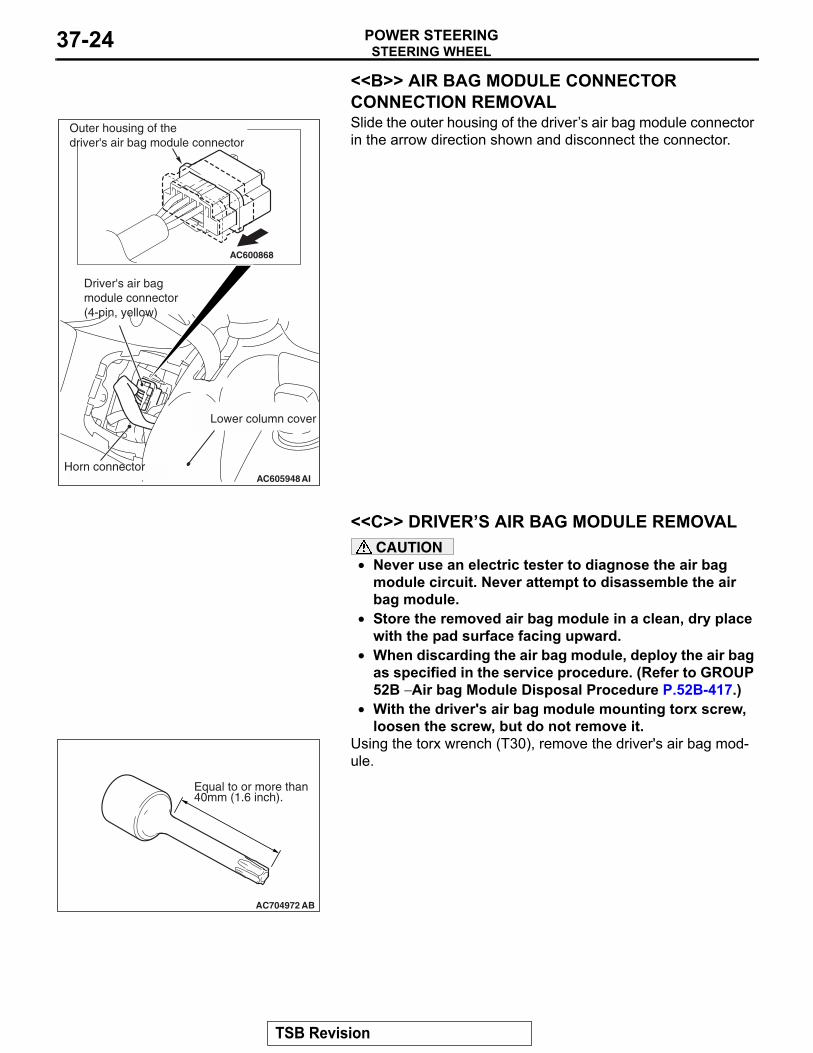
<<B>> AIR BAG MODULE CONNECTOR CONNECTION REMOVAL
AC605948
AC600868
AI
Lower column cover
Driver's air bagmodule connector(4-pin, yellow)
Horn connector
Outer housing of thedriver's air bag module connector
Slide the outer housing of the driver�s air bag module connector in the arrow direction shown and disconnect the connector.
.
<<C>> DRIVER�S AIR BAG MODULE REMOVALCAUTION
• Never use an electric tester to diagnose the air bag module circuit. Never attempt to disassemble the air bag module.
• Store the removed air bag module in a clean, dry place with the pad surface facing upward.
• When discarding the air bag module, deploy the air bag as specified in the service procedure. (Refer to GROUP 52B − Air bag Module Disposal Procedure P.52B-417.)
•
AC704972 AB
Equal to or more than40mm (1.6 inch).
With the driver's air bag module mounting torx screw, loosen the screw, but do not remove it.
Using the torx wrench (T30), remove the driver's air bag mod-ule.
.
TSB Revision

STEERING WHEELPOWER STEERING 37-25
<<D>> STEERING WHEEL ASSEMBLY REMOVAL1. Position the steering wheel in a straight ahead position.
CAUTION• Use the special tool to remove the steering wheel since
the steering column collision adsorbing mechanism may be damaged.
2.
AC705717AB
MB990803
Use special tool MB990803 to remove the steering wheel.
INSTALLATION SERVICE POINTS.
>>A<< STEERING WHEEL ASSEMBLY INSTALLA-TIONAfter centering the clock spring (Refer to 52B − Air bag module clock spring ), install the steering wheel assembly..
>>B<< AIR BAG MODULE CONNECTOR CONNECTION/AUDIO CONTROL SWITCH CONNECTOR CONNECTION/HORN CONNECTOR CONNECTION INSTALLATIONConnect the connector securely and route the harnesses not to lie off the cover hole.
TSB Revision

STEERING SHAFTPOWER STEERING37-26
STEERING SHAFTREMOVAL AND INSTALLATION
M1372011500953
CAUTION• Before removing the steering wheel assembly and driver's air bag module/knee air bag module,
always refer to GROUP 52B − Service Precautions P.52B-25 and Air bag Module and Clock Spring P.52B-386 or Knee Air bag Module P.52B-398.)
• After installation, perform a calibration for the ASC-ECU to learn the steering wheel sensor neutral point. (Refer to GROUP 35C − On-vehicle Service, Steering Wheel Sensor Calibration P.35C-267.)
Pre-removal Operation• Steering wheel at straight-ahead position check• Steering wheel assembly removal (Refer to P.37-22.)• Instrument panel cover lower removal (Refer to GROUP
52A − Instrument Lower Panel P.52A-8.) <MR>• Knee air bag module removal (Refer to GROUP 52B −
Driver's Knee Air Bag Module P.52B-398.)
Post-installation Operation• Instrument panel cover lower installation (Refer to
GROUP 52A − Instrument Lower Panel P.52A-8.) <MR>• Steering wheel assembly installation (Refer to P.37-22.)• Steering wheel straight-ahead position check
AC709222AB
5
9
3
2
7
1
84
11
2.5 ± 0.5 N·m23 ± 4 in-lb
12 ± 3 N·m9 ± 2 ft-lb
28 ± 7 N·m21 ± 5 ft-lb
5
3
10
A
A
BB
C
C
5
3
5
3
7.0 ± 3.0 N·m62 ± 27 in-lb
6
Section A-A
Claw
Section C-C
Claw
Section B-B
Claw
Note: claw position is symmetrical
20 ± 5 N·m15 ± 3 ft-lb
2.5 ± 0.5 N·m23 ± 4 in-lb
Removal steps <<A>> 1. Knob cap <Vehicles with
KOS>2. Ignition key cover3. Steering column lower cover4. Steering column protector
• Receiver antenna module removal (Refer to GROUP 42B − Exterior Transmitter Antenna Assembly, Interior Transmitter Antenna Assembly, Receiver Antenna Module P.42B-279.) <Vehicles with KOS>
Removal steps (Continued)
TSB Revision
STEERING SHAFTPOWER STEERING 37-27
REMOVAL SERVICE POINTS.
<<A>> KNOB CAP REMOVALRemove the knob cap while pressing the two projections..
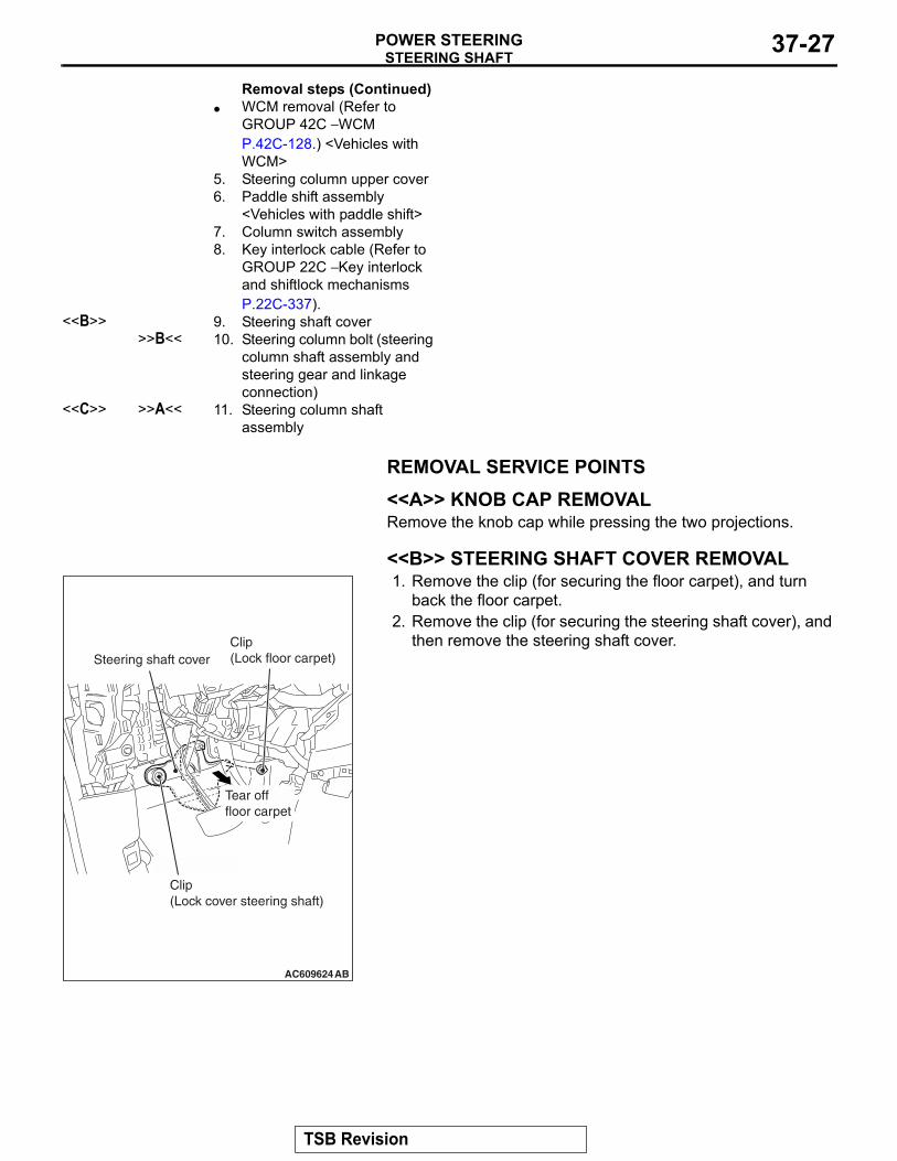
<<B>> STEERING SHAFT COVER REMOVAL
AC609624AB
Clip(Lock cover steering shaft)
Steering shaft coverClip(Lock floor carpet)
Tear offfloor carpet
1. Remove the clip (for securing the floor carpet), and turn back the floor carpet.
2. Remove the clip (for securing the steering shaft cover), and then remove the steering shaft cover.
.
• WCM removal (Refer to GROUP 42C − WCM P.42C-128.) <Vehicles with WCM>
5. Steering column upper cover6. Paddle shift assembly
<Vehicles with paddle shift>7. Column switch assembly8. Key interlock cable (Refer to
GROUP 22C − Key interlock and shiftlock mechanisms P.22C-337).
<<B>> 9. Steering shaft cover>>B<< 10. Steering column bolt (steering
column shaft assembly and steering gear and linkage connection)
<<C>> >>A<< 11. Steering column shaft assembly
Removal steps (Continued)
TSB Revision

STEERING SHAFTPOWER STEERING37-28
<<C>> STEERING COLUMN SHAFT ASSEMBLY DISCONNECTION
AC700371AD
Shaft B
Shaft AClip
Claw
Disconnect the steering gear from the steering column shaft assembly while sliding shaft A to shaft B with the clip claw as shown in the figure being pinched.
INSTALLATION SERVICE POINT.
>>A<< Steering column shaft assembly installa-tion1. Ensure that the tilt lever is in the lock position.
AC705591
b
a
c
AB
Tilt lever
2. Temporarily tighten the mounting bolts in the order of a, b, and c, and then tighten them in the order of c, b, and a to the specified torque.
Tightening torque a: 28 ± 7 N⋅ m (21 ± 5 ft-lb)Tightening torque b,c: 12 ± 3 N⋅ m (9 ± 2 ft-lb)
.
TSB Revision

STEERING SHAFTPOWER STEERING 37-29
>>B<< Steering column bolt (connection of steering column shaft assembly and steering gear and linkage) installation
AC700698AC
Yoke steering columnassembly
Bolt hole(Tapped hole)
Bolt hole(No tapped hole)
Steering column bolt
Clip
Claw
Steeringcolumn bolt
Shaft B
Shaft A
1. While sliding shaft A from shaft B with the clip claw as shown in the figure being pinched, connect the steering column shaft assembly and the steering gear and linkage.
2. Insert the steering column bolt from the no tapped bolt hole, and tighten it to the specified torque.
Tightening torque : 20 ± 5 N⋅ m (15 ± 3 ft-lb)
DISASSEMBLY AND REASSEMBLYM1372011700496
AC704984AB
N 12
4
3
Removal steps <<A>> >>A<< 1. Steering lock bolt
>>A<< 2. Steering lock bracket>>A<< 3. Steering lock cylinder
assembly4. Steering column shaft
assembly
Removal steps (Continued)
TSB Revision

STEERING SHAFTPOWER STEERING37-30
DISASSEMBLY SERVICE POINT.
<<A>> STEERING LOCK BOLT REMOVAL
AC705585AB
Steering lockbracket
Steeringlock bolt
Reverse screw tap
Steering lockcylinder assembly
1. Use a drill to make a hole just deeply enough for the tap to stand on the steering lock bolt.
2. Use a left-hand thread tap to remove the steering lock bolt.
ASSEMBLY SERVICE POINT.
>>A<< STEERING LOCK CYLINDER ASSEM-BLY/STEERING LOCK BRACKET/STEERING LOCK BOLT INSTALLATION1. When installing the steering lock assembly to the steering
column shaft assembly, temporarily assemble the steering lock assembly while aligning it with the boss on the column.
ACX01139AC
2. Make sure that the steering lock operates normally, and then tighten the steering lock bolt until its head is broken off.
TSB Revision

POWER STEERING GEAR BOX AND LINKAGEPOWER STEERING 37-31
POWER STEERING GEAR BOX AND LINKAGEREMOVAL AND INSTALLATION
M1372010901285
CAUTION• Before removing the steering wheel assembly and driver's air bag module, always refer to GROUP
52B − Service Precautions P.52B-25 and Air bag Module and Clock Spring P.52B-386. Also, posi-tion the front wheels in a straight ahead direction. If you fail to do this, clock spring for SRS may get damage, making the SRS (air bag) inoperative, and it may cause a serious injury to the driver.
• *: Indicates the bolts and nuts with friction coefficient stabilizer. In removal, ensure there is no damage, clean dust and soiling from bearing and thread surfaces, and tighten them to the speci-fied torque.
• After installation, perform a calibration for the ASC-ECU to learn the steering wheel sensor neutral point. (Refer to GROUP 35C − On-vehicle Service, Steering Wheel Sensor Calibration P.35C-267).
Pre-removal Operation• Power steering fluid draining (Refer to P.37-18).• Steering wheel and air bag module assembly removal
(Refer to P.37-22).• Steering shaft cover removal (Refer to P.37-26).• Engine room under cover front (A, B) and engine room
side cover removal (Refer to GROUP 51 − Under Cover P.51-16).
• Lower arm removal (Refer to GROUP 33 − Lower Arm P.33-15).
• Center member and front roll stopper assembly removal (Refer to GROUP 32 − Engine Roll Stopper and Center Member P.32-10).
Post-installation Operation• Center member and front roll stopper assembly installa-
tion (Refer to GROUP 32 − Engine Roll Stopper and Cen-ter Member P.32-10).
• Lower arm installation (Refer to GROUP 33 − Lower Arm P.33-15).
• Engine room under cover front (A, B) and engine room side cover installation (Refer to GROUP 51 − Under Cover P.51-16).
• Steering shaft cover removal (Refer to P.37-26).• Steering wheel and air bag module assembly installation
(Refer to P.37-22).• Using your fingers, press the dust cover of joints to check
for a crack or damage.• Power steering fluid filling (Refer to P.37-18).• Air bleeding of power steering fluid (Refer to P.37-19).• Steering wheel at straight-ahead position check
TSB Revision

POWER STEERING GEAR BOX AND LINKAGEPOWER STEERING37-32
AC708302AB
4
57 ± 7 N·m42 ± 5 ft-lb
3
10
8
116
2
N
N
12
15
13
5.0 ± 2.0 N·m45 ± 17 in-lb
20 ± 5 N·m15 ± 3 ft-lb
5
7
14
9
9
150 ± 5 N·m37 ± 4 ft-lb
70 ± 10 N·m52 ± 7 ft-lb
40 ± 8 N·m30 ± 5 ft-lb
110 ± 11 N·m81 ± 8 ft-lb
28 ± 4 N·m21 ± 3 ft-lb
110 ± 11 N·m81 ± 8 ft-lb
28 ± 4 N·m21 ± 3 ft-lb
53 ± 8 N·m39 ± 6 ft-lb
Removal steps >>B<< 1. Steering column bolt (steering
column shaft assembly and steering gear and linkage connection)
<<A>> 2. steering column shaft assembly and steering gear and linkage connection
<<B>> 3. Self-lock nut (Tie-rod end and knuckle connection)
4. Eye bolt5. Pressure hose connection6. Gasket
7. Return hose connection8. Engine rear roll stopper
bracket connecting bolt9. Front axle crossmember stay
<<C>> 10. Front axle cossmember assembly
11. Engine rear roll stopper12. Heat protector
>>A<< 13. Joint cover grommet14. Flunge bolt15. Steering gear and linkage
assembly
Removal steps (Continued)
TSB Revision

POWER STEERING GEAR BOX AND LINKAGEPOWER STEERING 37-33
REMOVAL SERVICE POINTS.
<<A>> DISCONNECTION OF STEERING COL-UMN SHAFT ASSEMBLY AND STEERING GEAR AND LINKAGE
AC700371AD
Shaft B
Shaft AClip
Claw
Disconnect the steering gear from the steering column shaft assembly while sliding shaft A to shaft B with the clip claw as shown in the figure being pinched.
.
<<B>> SELF-LOCK NUT (TIE-ROD END AND KNUCKLE CONNECTION) REMOVAL
CAUTION• Loosen the self-locking nut (tie-rod end connection)
from the ball joint, but do not remove here. Use the spe-cial tool.
•
AC208247AJ
Cord
Bolt
MB991897orMB992011
Nut
Ball joint
To prevent the special tool from dropping off, suspend it with a rope.
1. Install special tool MB991897 or MB992011 as shown in the figure.
AC104739AB
Parallel
Knob
Bolt
Correct
Wrong
2. Turn the bolt and knob to make the special tool jaws parallel, then hand-tighten the bolt. After tightening, check that the jaws are still parallel.NOTE: To adjust the special tool jaws to be parallel, set the orientation of the knob as shown in the figure.
3. Unscrew the bolt to disconnect the ball joint.
.
TSB Revision

POWER STEERING GEAR BOX AND LINKAGEPOWER STEERING37-34
<<C>> FRONT SUSPENSION CROSSMEMBER REMOVAL
AC609888
Piece of wood
Transmission jack
AB
1. Jack up and support the crossmember, and remove it.2. Check the hoses and harnesses for roughness, and then
remove the front suspension crossmember with the rear roll stopper and the steering gear and linkage installed.
INSTALLATION SERVICE POINTS.
>>A<< JOINT COVER GROMMET INSTALLATION
AC609889AB
Steering jointcover assembly
Joint covergrommet
Steering gear
Protrusion part
Install by aligning the marks of joint cover grommet and steer-ing gear and linkage as shown in the figure.
.
>>B<< Steering column bolt (connection of steering column shaft assembly and steering gear and linkage) installation
AC700698AC
Yoke steering columnassembly
Bolt hole(Tapped hole)
Bolt hole(No tapped hole)
Steering column bolt
Clip
Claw
Steeringcolumn bolt
Shaft B
Shaft A
1. While sliding shaft A from shaft B with the clip claw as shown in the figure being pinched, connect the steering column shaft assembly and the steering gear and linkage.
2. Insert the steering column bolt from the no tapped bolt hole, and tighten it to the specified torque.
Tightening torque : 20 ± 5 N⋅ m ( 15 ± 3 ft-lb)
TSB Revision
POWER STEERING GEAR BOX AND LINKAGEPOWER STEERING 37-35
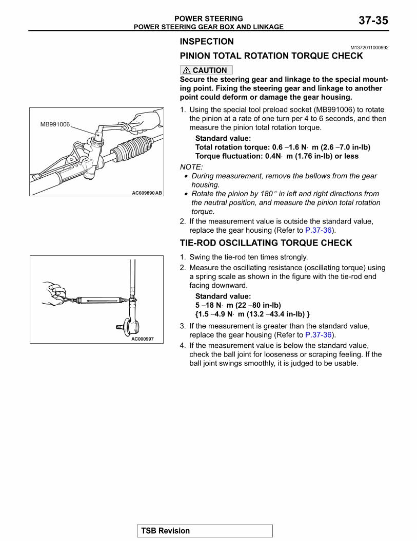
INSPECTIONM1372011000992
PINION TOTAL ROTATION TORQUE CHECKCAUTION
Secure the steering gear and linkage to the special mount-ing point. Fixing the steering gear and linkage to another point could deform or damage the gear housing..
AC609890
MB991006
AB
1. Using the special tool preload socket (MB991006) to rotate the pinion at a rate of one turn per 4 to 6 seconds, and then measure the pinion total rotation torque.
Standard value: Total rotation torque: 0.6 − 1.6 N⋅ m (2.6 − 7.0 in-lb) Torque fluctuation: 0.4N⋅ m (1.76 in-lb) or less
NOTE: .• During measurement, remove the bellows from the gear
housing.• Rotate the pinion by 180° in left and right directions from
the neutral position, and measure the pinion total rotation torque.
2. If the measurement value is outside the standard value, replace the gear housing (Refer to P.37-36).
TIE-ROD OSCILLATING TORQUE CHECK.
AC000997
1. Swing the tie-rod ten times strongly.2. Measure the oscillating resistance (oscillating torque) using
a spring scale as shown in the figure with the tie-rod end facing downward.
Standard value: 5 − 18 N⋅ m (22 − 80 in-lb) {1.5 − 4.9 N⋅ m (13.2 − 43.4 in-lb) }
3. If the measurement is greater than the standard value, replace the gear housing (Refer to P.37-36).
4. If the measurement value is below the standard value, check the ball joint for looseness or scraping feeling. If the ball joint swings smoothly, it is judged to be usable.
TSB Revision

POWER STEERING GEAR BOX AND LINKAGEPOWER STEERING37-36
DISASSEMBLY AND REASSEMBLYM1372011100825
AC708310
Flare nut
58 ± 7 N·m43 ± 5 ft-lb
27 ± 2 N·m20 ± 2 ft-lb
546
72
1
3
AB
1
Removal steps 1. Feed pipe
>>B<< 2. Tie-rod end>>B<< 3. Locking nut>>B<< 4. Clip
>>A<< 5. Band6. Bellows7. Gear housing
LUBRICATION AND SEALING POINTS
AC709293AB
Sealant: 3MTM AAD Part No. 8663 or equivalentGrease: Silicone grease
Removal steps (Continued)
TSB Revision

POWER STEERING GEAR BOX AND LINKAGEPOWER STEERING 37-37
ASSEMBLY SERVICE POINT.
>>A<< BAND INSTALLATIONCAUTION
• Secure the rack housing, and firmly crimp the bellows band by the bellows band clipping tool (special tool: MB992209).
•
AC701769
MB992209
AD
Crimp the bellows band securely until the special tool (MB992209) contacts the stopper.
1. Using the special tool (MB992209), crimp the bellows band.
ACX01166 AC
A
2. Check that the crimping width of the band (A) is within the range of the standard value.
Standard value (A): 2.4 − 2.8 mm (0.09 − 0.11 in)
.
>>B<< TIE-ROD END/LOCKING NUT INSTALLATION
AC703667
198 mm (7.7in)
AC
Lock nutEdge of bellowsassembly groove
Screw in the tie-rod to the length shown in the figure, and hand-tighten the locking nut.NOTE: Install the steering gear and linkage to the body, adjust the toe-in, and then tighten the locking nut to the specified torque.
TSB Revision
POWER STEERING OIL PUMP ASSEMBLYPOWER STEERING37-38
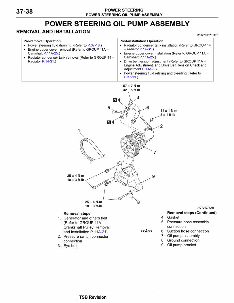
POWER STEERING OIL PUMP ASSEMBLYREMOVAL AND INSTALLATION
M1372005201172
Pre-removal Operation• Power steering fluid draining (Refer to P.37-18.)• Engine upper cover removal (Refer to GROUP 11A −
Camshaft P.11A-25.)• Radiator condenser tank removal (Refer to GROUP 14 −
Radiator P.14-31.)
Post-installation Operation• Radiator condenser tank installation (Refer to GROUP 14
− Radiator P.14-31.)• Engine upper cover installation (Refer to GROUP 11A −
Camshaft P.11A-25.)• Drive belt tension adjustment (Refer to GROUP 11A −
Engine Adjustment, and Drive Belt Tension Check and Adjustment P.11A-8.)
• Power steering fluid refilling and bleeding (Refer to P.37-19.)
AC704977AB
12
57 ± 7 N·m42 ± 5 ft-lb
34N
25 ± 4 N·m18 ± 3 ft-lb
8
11 ± 1 N·m8 ± 1 ft-lb
6
4N
5
9
7
25 ± 4 N·m18 ± 3 ft-lb
Removal steps 1. Generator and others belt
(Refer to GROUP 11A − Crankshaft Pulley Removal and Installation P.11A-21).
2. Pressure switch connector connection
3. Eye bolt
4. Gasket5. Pressure hose assembly
connection>>A<< 6. Suction hose connection
7. Oil pump assembly8. Ground connection9. Oil pump bracket
Removal steps (Continued)
TSB Revision

POWER STEERING OIL PUMP ASSEMBLYPOWER STEERING 37-39
INSTALLATION SERVICE POINT.
>>A<< SUCTION HOSE INSTALLATION
AC708493 AC
Marking
Oil pump
Suction hose
Vehicle front side
Install the suction hose with its marking located as shown in the figure.
TSB Revision

POWER STEERING HOSESPOWER STEERING37-40
POWER STEERING HOSESREMOVAL AND INSTALLATION
M1372005701382
Pre-removal Operation• Power steering fluid draining (Refer to P.37-18.)• Front bumper assembly removal (Refer to GROUP 51,
Front Bumper Assembly and Radiator Grille P.51-3.)• Headlight (RH) removal (Refer to GROUP 54A P.54A-184
Headlight.)• Strut tower bar removal (Refer to GROUP 42A P.42A-15
Strut Tower Bar.)• Engine upper cover removal (Refer to GROUP 11A −
Camshaft P.11A-25.)
Post-installation Operation• Strut tower bar installation (Refer to GROUP 42A − Strut
Tower Bar P.42A-15.)• Headlight (RH) installation (Refer to GROUP 54A − Head-
light P.54A-184.)• Front bumper assembly installation (Refer to GROUP 51 −
Front Bumper Assembly and Radiator Grille P.51-3.)• Power steering fluid refilling and bleeding (Refer to
P.37-19.)• Engine upper cover installation (Refer to GROUP 11A −
Camshaft P.11A-25.)
AC708301AB
13 ± 2 N·m9.0 ± 2.0 ft-lb
10
3
N 4
5
N
N6
2
14
13
11
7
15
161
8
9
12
13 ± 2 N·m9.0 ± 2.0 ft-lb
13 ± 2 N·m9.0 ± 2.0 ft-lb
57 ± 7 N·m42 ± 5 ft-lb
57 ± 7 N·m42 ± 5 ft-lb
15 ± 3 N·m11 ± 2 ft-lb
13 ± 2 N·m9.0 ± 2.0 ft-lb
13 ± 2 N·m9 ± 2 ft-lb
13 ± 2 N·m9 ± 2 ft-lb
Removal steps 1. Oil reservoir
>>D<< 2. Suction hose3. Eye bolt4. Gasket5. Eye bolt6. Gasket
>>C<< 7. Pressure hose8. Pressure hose bracket
>>B<< 9. Return hose10. Return tube11. Gasket
>>A<< 12. Return tube>>B<< 13. Return hose>>B<< 14. Return hose>>A<< 15. Return tube>>A<< 16. Cooler tube assembly
Removal steps (Continued)
TSB Revision

POWER STEERING HOSESPOWER STEERING 37-41
INSTALLATION SERVICE POINTS.
>>A<< COOLER TUBE ASSEMBLY/RETURN TUBE ASSEMBLY INSTALLATION
AC704781AC
Cooler tube assembly
Return tube
Marking Marking
Install by aligning the mating marks of cooler tube assembly and return tube assembly.
.
>>B<< RETURN HOSE INSTALLATION
AC612002AB
Return hose
Marking
1. Install the return hose by aligning the mating marks.
AC705437AB
Marking
Return hose
Oil reservoir
2. Install the return hose with its marking located as shown in the figure.
TSB Revision
POWER STEERING HOSESPOWER STEERING37-42
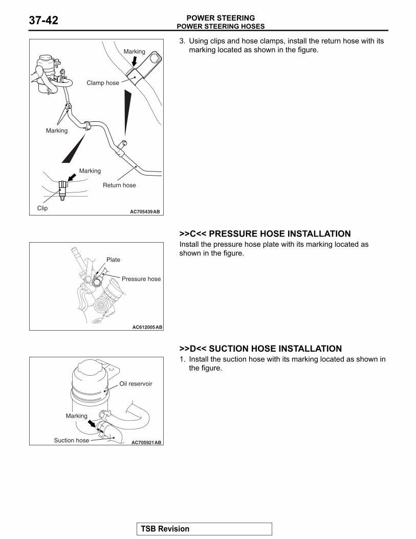
AC705439AB
Return hose
Marking
Clip
Clamp hose
Marking
Marking
3. Using clips and hose clamps, install the return hose with its marking located as shown in the figure.
.
>>C<< PRESSURE HOSE INSTALLATION
AC612005AB
Plate
Pressure hose
Install the pressure hose plate with its marking located as shown in the figure.
.
>>D<< SUCTION HOSE INSTALLATION
AC705921AB
Marking
Suction hose
Oil reservoir
1. Install the suction hose with its marking located as shown in the figure.
TSB Revision

POWER STEERING HOSESPOWER STEERING 37-43
AC708493 AC
Marking
Oil pump
Suction hose
Vehicle front side
2. Install the suction hose with its marking located as shown in the figure.
TSB Revision

NOTES