Embed Size (px)
Citation preview
GridShield® outdoor vacuum reclosers 15-38 kVMaking distribution networks more reliable
2 GridShield | Descriptive bulletin
Table of contents
Introduction ............................................................................................................................................................................. 3Recloser technology ................................................................................................................................................................ 4
Magnetic actuators .............................................................................................................................................................. 4Position switch .................................................................................................................................................................... 4Trip handle ......................................................................................................................................................................... 4Vacuum interrupters ............................................................................................................................................................. 5Pole assembly ..................................................................................................................................................................... 5HCEP insulating material ...................................................................................................................................................... 5
Recloser control ...................................................................................................................................................................... 7RER620 overview................................................................................................................................................................. 7RER620 advantages ............................................................................................................................................................ 7RER620 hardware features ................................................................................................................................................... 8RER620 display ................................................................................................................................................................... 9PCM600 .............................................................................................................................................................................10Web HMI ............................................................................................................................................................................11
Technical data.........................................................................................................................................................................12Ordering guide ........................................................................................................................................................................14
GridShield ..........................................................................................................................................................................14GridShield 3SP ...................................................................................................................................................................16
GridShield dimensions ............................................................................................................................................................18GridShield and GridShield 3SP control cabinet dimensions ...................................................................................................19GridShield 3SP dimensions ....................................................................................................................................................20Accessories ............................................................................................................................................................................22Additional ABB devices ..........................................................................................................................................................24Service & support ...................................................................................................................................................................25Notes ......................................................................................................................................................................................27
Descriptive bulletin | GridShield 3
IntroductionGridShield® - making distribution networks more reliable
ABB’s drive to produce the most advanced feeder automation equipment and to exceed user expectations has led to the development of the new GridShield recloser. Paired with the industry’s most intelligent electronic device - the RER620 - the GridShield recloser is a product of extensive research and testing, creating the most reliable and technically adept recloser on the market. Whether performing single- or three-phase tripping, connecting distributed generation to the grid or communicating via IEC 61850 utilizing GOOSE messaging, the GridShield recloser is ready for any application.
Offering − GridShield single tank three-phase recloser − GridShield 3SP three pole mounted three-phase recloser for
mounting flexibility − GridShield control cabinet with RER620 control backwards
compatible to support 15/27 kV OVR-3 and OVR-3SP reclosers
Features − Ability to perform as a recloser, sectionalizer or automated
load-break switch − Recloser platforms for both single- and three-phase system
applications for improved system reliability
− Proven modular design rated for 10,000 full load operations − Hydrophobic Cycloaliphatic Epoxy (HCEP) insulation provides
industry-leading reliability − No maintenance required for the recloser unit − Stainless steel used in both the recloser and control cabinets
for durability in any environment − Low profile control cabinet (LPCC) option is available for ap-
plications where a smaller footprint is required − All electronics located inside control cabinet for easy and
safe access, reducing maintenance costs as the electronic controls can be accessed without using bucket trucks or climbing poles (especially helpful at night or during restora-tions in bad weather)
− Operation of the recloser does not depend on batteries as battery power is only used for backup power when AC is lost
− Simple integration into Ethernet or serial-based communi-cation networks with DNP3 Level 2, Modbus, IEC 61850, GOOSE, IEC 60870-5-101/104, and PG&E 2179
− Web browser interface for easy setting and record retrieval − Advanced RER620 control with programmable pushbuttons
and a fully customizable faceplate − IEC 61850 compliant PCM600 tool suite for all ABB Relion®
relays
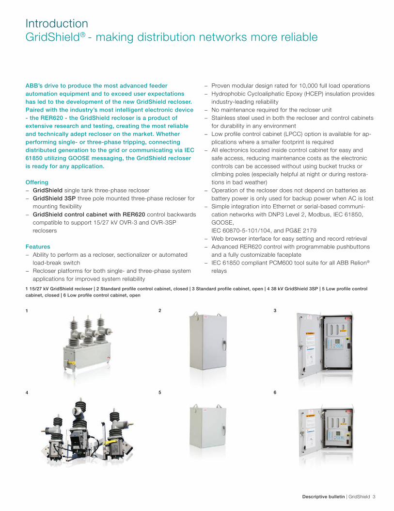
1 15/27 kV GridShield recloser | 2 Standard profile control cabinet, closed | 3 Standard profile cabinet, open | 4 38 kV GridShield 3SP | 5 Low profile control cabinet, closed | 6 Low profile control cabinet, open
5
2
6
3
4
1
4 GridShield | Descriptive bulletin
GridShield reclosers have proven field performance using innovative technologies and advanced expertise. ABB has created the most reliable, lowest maintenance solution for recloser applications by incorporating the latest magnetic actuation technology, high quality vacuum interrupters, and HCEP (Hydrophobic Cycloaliphatic Epoxy) solid dielectric insulation material. As a result, the ABB GridShield recloser is unparalleled in durability and value.
Magnetic actuatorsABB designed a simple, magnetically actuated operating me-chanism that could dependably operate 10,000 timeswith minimal moving parts. OVR magnetic actuators have a black zinc oxide plating, making them more resistant tocorrosion than older magnetic actuators that used traditional yellow zinc plating. Bi-stable operation was added to allow OVR reclosers to remain in either the open or closed position, even when power is lost. Three-phase models are equipped with one magnetic actuator per pole to allow for single-phase tripping, and to eliminate complicated linkages.
As a result of these capabilities, ABB is the leader in magnetic actuation technology.
Advantages − 10,000 full load operations − No lubrication, maintenance, or adjustments − Up to 16 kA fault make and break capability − Bi-stable - no power required to hold contacts open or
closed − Single phase tripping capability
Position switchThe ultra-durable position switch was selected for its ability to operate dependably for the 10,000 operation lifetime of all GridShield reclosers.
Advantages − Determines pole open or closed positions − Allows independent pole operation − Provides positive pole position feedback to the GridShield
control unit − Double break, galvanically separate contacts − Self-cleaning contacts through wiping action − Contact position and internal mechanism easily viewed
through the housing
Trip handleBlock close (69 function) is standard on all GridShield reclosers. The 69 switch is wired to a relay input and programmed to pre-vent a local or remote close.
− Few moving parts − 10,000 full load operations without maintenance − Single molded design guarantees the longest creepage dis-
tance in the industry
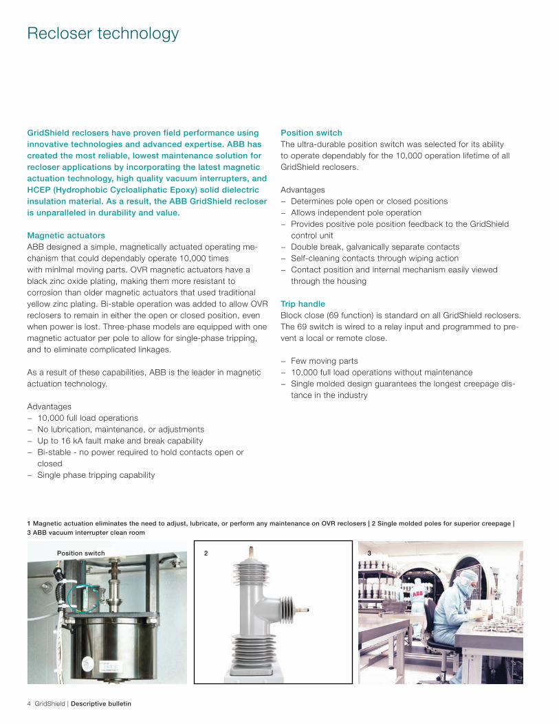
1 Magnetic actuation eliminates the need to adjust, lubricate, or perform any maintenance on OVR reclosers | 2 Single molded poles for superior creepage | 3 ABB vacuum interrupter clean room
2 31
Recloser technology
Position switch
Descriptive bulletin | GridShield 5
Vacuum interruptersGridShield recloser HCEP poles have a modular design, each with its own embedded vacuum interrupter.
ABB has been developing and manufacturing vacuum interrup-ters since the early 1980s. Worldwide, more than two million ABB vacuum interrupters are in service. ABB’s vacuum interrup-ter facility uses the latest technologies in high quality massproduction to produce the most advanced and reliable vacuum interrupters.
Vacuum technology fits well with the recloser requirements since it can easily handle frequent operations. Additionally, vacuuminterrupters are capable of reclosing as soon as 100 msec.
Advantages − Maximum reliability − Superior contact wear − Long life: 10,000 full load operations − No maintenance − Environmentally friendly
Pole assembly − Modular assembly for easy replacement in the field − Pole embedded 10,000:1 CVDs and 600:1 CTs − UV protected for environmental durability − Molded design reduces risk of tampering
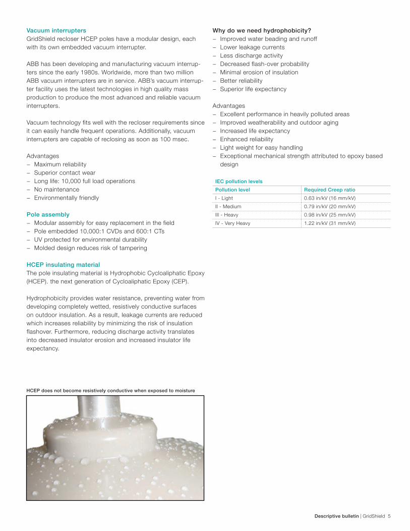
HCEP insulating materialThe pole insulating material is Hydrophobic Cycloaliphatic Epoxy (HCEP). the next generation of Cycloaliphatic Epoxy (CEP).
Hydrophobicity provides water resistance, preventing water from developing completely wetted, resistively conductive surfaces on outdoor insulation. As a result, leakage currents are reduced which increases reliability by minimizing the risk of insulation flashover. Furthermore, reducing discharge activity translates into decreased insulator erosion and increased insulator life expectancy.
Why do we need hydrophobicity? − Improved water beading and runoff − Lower leakage currents − Less discharge activity − Decreased flash-over probability − Minimal erosion of insulation − Better reliability − Superior life expectancy
Advantages − Excellent performance in heavily polluted areas − Improved weatherability and outdoor aging − Increased life expectancy − Enhanced reliability − Light weight for easy handling − Exceptional mechanical strength attributed to epoxy based
design
HCEP does not become resistively conductive when exposed to moisture
IEC pollution levels
Pollution level Required Creep ratio
I - Light 0.63 in/kV (16 mm/kV)
II - Medium 0.79 in/kV (20 mm/kV)
III - Heavy 0.98 in/kV (25 mm/kV)
IV - Very Heavy 1.22 in/kV (31 mm/kV)

6 GridShield | Descriptive bulletin
GridShield at KIPTS test siteKIPTS test site in South Africa
Required creep vs GridShield creep (Phase to Ground)
Pollution
Level
Rated Maximum Voltage
15 kV 27 kV 38 kV2
Required creep
in (mm)
OVR creep
in (mm)
Required creep
in (mm)
OVR creep
in (mm)
Required creep
in (mm)
OVR creep
in (mm)
I - Light 9.8 (248) 17.0 (432) 23.9 (608)
II - Medium 12.2 (310) 21.3 (540) 30.0 (760)
III - Heavy 15.3 (388) 26.6 (675) 37.4 (950)
IV - Very Heavy 18.9 (481) 38.0 (960) 33.0 (837) 38.0 (960) 46.4 (1178) 50.7 (1288)
IEC pollution levels
Pollution level Required Creep ratio
I - Light 0.63 in/kV (16 mm/kV)
II - Medium 0.79 in/kV (20 mm/kV)
III - Heavy 0.98 in/kV (25 mm/kV)
IV - Very Heavy 1.22 in/kV (31 mm/kV)
GridShield Severe Environment Test Results from KIPTS3: − PASSED - Testing for use in marine and industrial
environments − PASSED - No signs of material erosion, tracking, cracks, or
punctures reported For more information, please view the report on www.abb.com/mediumvoltage
1 as per applicable IEC standards
2 GridShield and GridShield 3SP only for 38 kV 3 Koeberg Insulator Pollution Test Station (KIPTS) is known internationally as a severe environmental testing facility run by ESKOM Electric Utility located approximately 17 miles (27 km) north of Cape Town, South Africa
Contamination performanceContamination performance is dependent on the amount of creepage/leakage distance available on a recloser bushing (pole). This is why all ABB GridShield reclosers come standard with HCEP insulation that exceeds IEC Level 4 requirements for environments with very heavy pollution1 - far more creep than required by equivalent ANSI standards, which focus mainly on BIL performance.
Descriptive bulletin | GridShield 7
RER620 overviewThe RER620, part of the Relion® family of ABB controls, is a dedicated IED perfectly aligned for the protection, control, measurement and supervision of utility substations and indus-trial power systems. The RER620 is an ideal solution for radial, looped and meshed distribution networks with or without dis-tributed power generation. The RER620 IED is characterized by its compact and drawout unit design.
Engineered from the ground up, the RER620 has been designed to unleash the full potential of the IEC 61850 standard for com-munication and interoperability. The RER620 provides main protection for overhead lines and cable feeders in distribution networks.
RER620 advantages − One common PCM600 configuration tool for Relion family
protection relays − Web browser interface for operators and linemen, eliminated
the need for software − High Impedance Fault (HIZ) detects downed conductor for
added safety around power lines − Ethernet and serial-based communications with: DNP3,
IEC 60870-5-101, IEC 60870-5-104, Modbus, IEC 61850 − Peer-to-peer GOOSE messaging for high-speed transfer
switching, and Fault Detection Isolation and Restoration (FDIR) schemes
− Up to 20 binary inputs and 14 binary outputs − Six setting groups for protection scheme flexibility − Embedded in-rush detection for reliability connecting distrib-
uted generation networks − Drawout design for quick and easy maintenance − Environmentally friendly design with Restriction of Hazardous
Substances Directive (RoHS) compliance − 12-year relay warranty
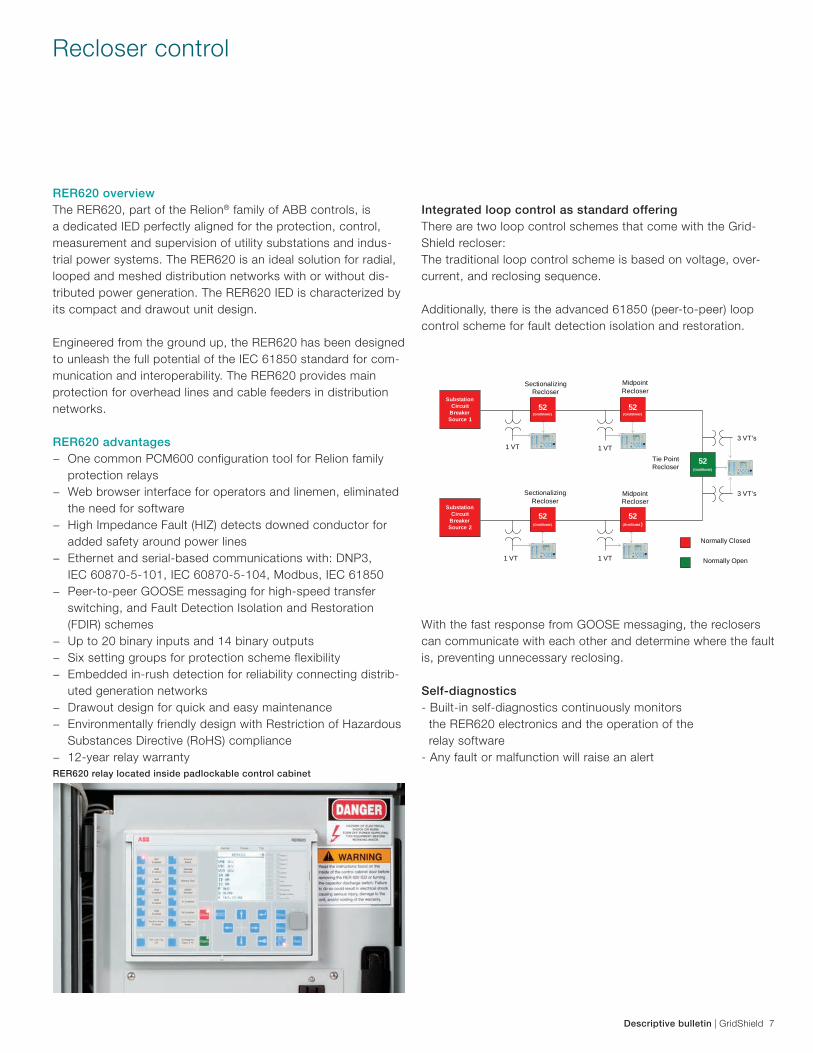
Integrated loop control as standard offeringThere are two loop control schemes that come with the Grid-Shield recloser: The traditional loop control scheme is based on voltage, over-current, and reclosing sequence.
Additionally, there is the advanced 61850 (peer-to-peer) loop control scheme for fault detection isolation and restoration.
With the fast response from GOOSE messaging, the reclosers can communicate with each other and determine where the fault is, preventing unnecessary reclosing.
Self-diagnostics- Built-in self-diagnostics continuously monitors the RER620 electronics and the operation of the relay software- Any fault or malfunction will raise an alert
Recloser control
RER620 relay located inside padlockable control cabinet
52(GridShield )
52(GridShield )
52(GridShield )
52(GridShield )
52(GridShield )
Substation Circuit
Breaker Source 1
Substation Circuit
Breaker Source 2
Sectionalizing Recloser
Midpoint Recloser
Tie Point Recloser
Sectionalizing Recloser
Midpoint Recloser
1 VT 1 VT
1 VT 1 VT
3 VT’s
3 VT’s
Normally Closed
Normally Open
8 GridShield | Descriptive bulletin
RER620 hardware features
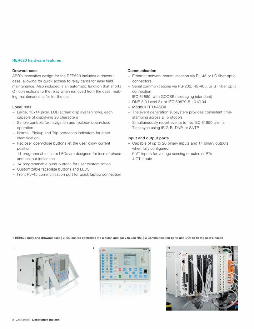
Drawout caseABB’s innovative design for the RER620 includes a drawout case, allowing for quick access to relay cards for easy field maintenance. Also included is an automatic function that shorts CT connections to the relay when removed from the case, mak-ing maintenance safer for the user.
Local HMI − Large, 13x14 pixel, LCD screen displays ten rows, each
capable of displaying 20 characters − Simple controls for navigation and recloser open/close
operation − Normal, Pickup and Trip protection indicators for state
identification − Recloser open/close buttons let the user know current
position − 11 programmable alarm LEDs are designed for loss of phase
and lockout indication − 14 programmable push-buttons for user customization − Customizable faceplate buttons and LEDS − Front RJ-45 communication port for quick laptop connection
Communication − Ethernet network communication via RJ-45 or LC fiber optic
connectors − Serial communications via RS-232, RS-485, or ST fiber optic
connection − IEC 61850, with GOOSE messaging (standard) − DNP 3.0 Level 2+ or IEC 60870-5-101/104 − Modbus RTU/ASCII − The event generation subsystem provides consistent time-
stamping across all protocols − Simultaneously report events to five IEC 61850 clients − Time sync using IRIG-B, DNP, or SNTP
Input and output ports − Capable of up to 20 binary inputs and 14 binary outputs
when fully configured − 6 VT inputs for voltage sensing or external PTs − 4 CT inputs
1 RER620 relay and drawout case | 2 IED can be controlled via a clean and easy to use HMI | 3 Communication ports and I/Os to fit the user’s needs
2 31
Descriptive bulletin | GridShield 9
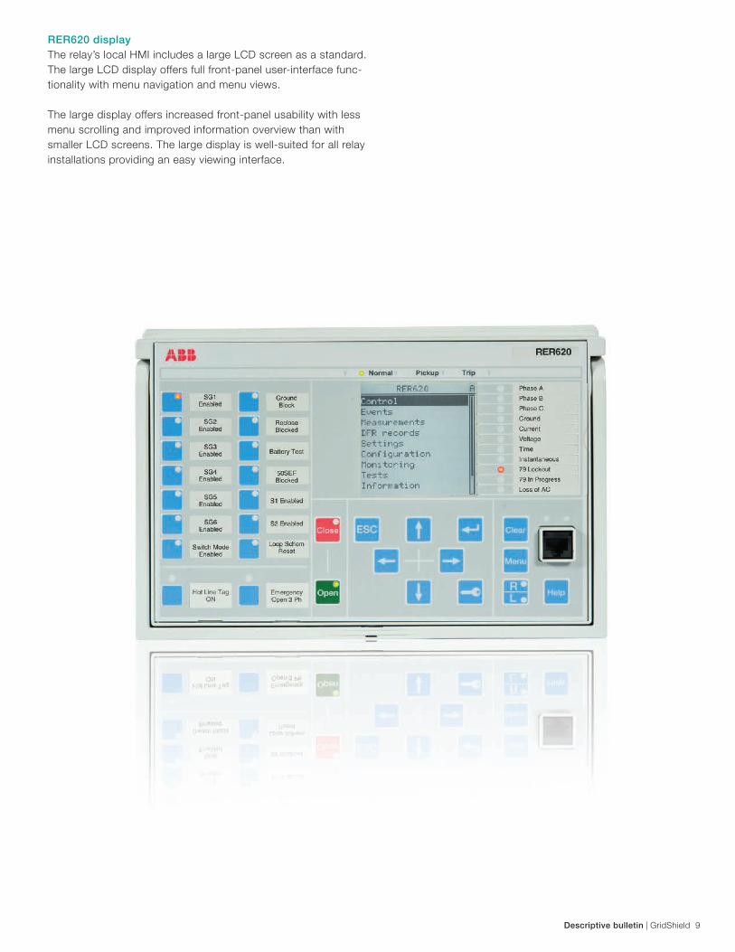
RER620 displayThe relay’s local HMI includes a large LCD screen as a standard. The large LCD display offers full front-panel user-interface func-tionality with menu navigation and menu views.
The large display offers increased front-panel usability with less menu scrolling and improved information overview than with smaller LCD screens. The large display is well-suited for all relay installations providing an easy viewing interface.
10 GridShield | Descriptive bulletin
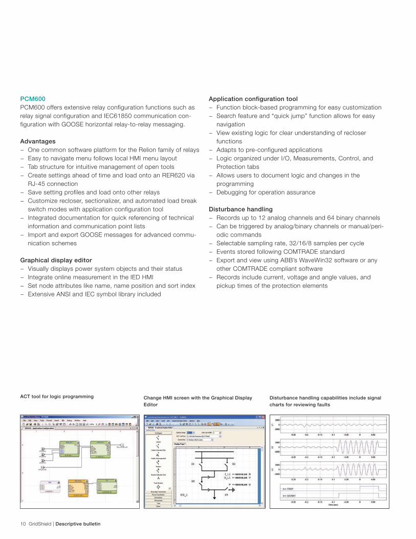
PCM600PCM600 offers extensive relay configuration functions such as relay signal configuration and IEC61850 communication con-figuration with GOOSE horizontal relay-to-relay messaging.
Advantages − One common software platform for the Relion family of relays − Easy to navigate menu follows local HMI menu layout − Tab structure for intuitive management of open tools − Create settings ahead of time and load onto an RER620 via
RJ-45 connection − Save setting profiles and load onto other relays − Customize recloser, sectionalizer, and automated load break
switch modes with application configuration tool − Integrated documentation for quick referencing of technical
information and communication point lists − Import and export GOOSE messages for advanced commu-
nication schemes
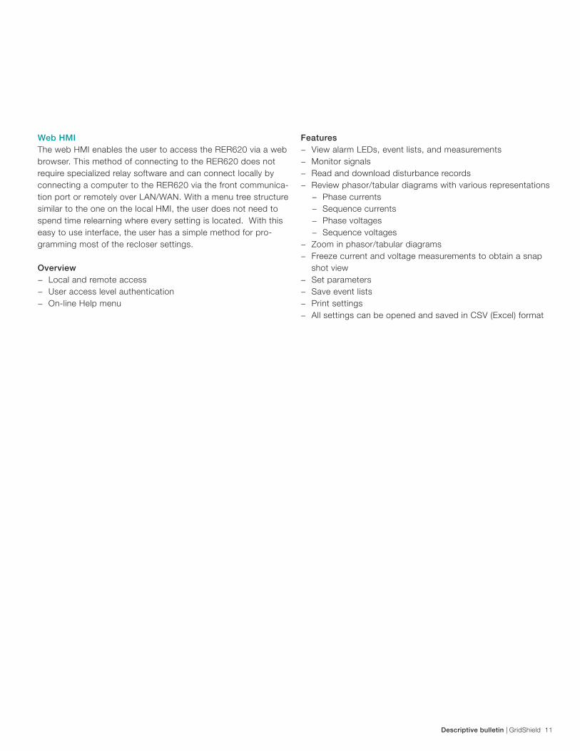
Graphical display editor − Visually displays power system objects and their status − Integrate online measurement in the IED HMI − Set node attributes like name, name position and sort index − Extensive ANSI and IEC symbol library included
Application configuration tool − Function block-based programming for easy customization − Search feature and “quick jump” function allows for easy
navigation − View existing logic for clear understanding of recloser
functions − Adapts to pre-configured applications − Logic organized under I/O, Measurements, Control, and
Protection tabs − Allows users to document logic and changes in the
programming − Debugging for operation assurance
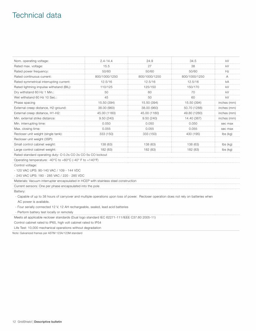
Disturbance handling − Records up to 12 analog channels and 64 binary channels − Can be triggered by analog/binary channels or manual/peri-
odic commands − Selectable sampling rate, 32/16/8 samples per cycle − Events stored following COMTRADE standard − Export and view using ABB’s WaveWin32 software or any
other COMTRADE compliant software − Records include current, voltage and angle values, and
pickup times of the protection elements
ACT tool for logic programming Change HMI screen with the Graphical Display Editor
Disturbance handling capabilities include signal charts for reviewing faults
Descriptive bulletin | GridShield 11
Web HMIThe web HMI enables the user to access the RER620 via a web browser. This method of connecting to the RER620 does not require specialized relay software and can connect locally by connecting a computer to the RER620 via the front communica-tion port or remotely over LAN/WAN. With a menu tree structure similar to the one on the local HMI, the user does not need to spend time relearning where every setting is located. With this easy to use interface, the user has a simple method for pro-gramming most of the recloser settings.
Overview − Local and remote access − User access level authentication − On-line Help menu
Features − View alarm LEDs, event lists, and measurements − Monitor signals − Read and download disturbance records − Review phasor/tabular diagrams with various representations
− Phase currents − Sequence currents − Phase voltages − Sequence voltages
− Zoom in phasor/tabular diagrams − Freeze current and voltage measurements to obtain a snap
shot view − Set parameters − Save event lists − Print settings − All settings can be opened and saved in CSV (Excel) format
12 GridShield | Descriptive bulletin
Nom. operating voltage: 2.4-14.4 24.9 34.5 kV
Rated max. voltage: 15.5 27 38 kV
Rated power frequency: 50/60 50/60 50/60 Hz
Rated continuous current: 800/1000/1250 800/1000/1250 800/1000/1250 A
Rated symmetrical interrupting current: 12.5/16 12.5/16 12.5/16 kA
Rated lightning impulse withstand (BIL): 110/125 125/150 150/170 kV
Dry withstand 60 Hz 1 Min.: 50 60 70 kV
Wet withstand 60 Hz 10 Sec.: 45 50 60 kV
Phase spacing 15.50 (394) 15.50 (394) 15.50 (394) inches (mm)
External creep distance, H2-ground: 38.00 (960) 38.00 (960) 50.70 (1288) inches (mm)
External creep distance, H1-H2: 45.00 (1160) 45.00 (1160) 49.80 (1260) inches (mm)
Min. external strike distance: 9.50 (240) 9.50 (240) 14.40 (367) inches (mm)
Min. interrupting time: 0.050 0.050 0.050 sec max
Max. closing time: 0.055 0.055 0.055 sec max
Recloser unit weight (single tank): 333 (150) 333 (150) 430 (195) lbs (kg)
Recloser unit weight (3SP):
Small control cabinet weight: 138 (63) 138 (63) 138 (63) lbs (kg)
Large control cabinet weight: 182 (83) 182 (83) 182 (83) lbs (kg)
Rated standard operating duty: O 0.2s CO 2s CO 5s CO lockout
Operating temperature: -40°C to +60°C (-40° F to +140°F)
Control voltage:
- 120 VAC UPS: 90-140 VAC / 109 - 144 VDC
- 240 VAC UPS: 180 - 285 VAC / 220 - 285 VDC
Materials: Vacuum interrupter encapsulated in HCEP with stainless steel construction
Current sensors: One per phase encapsulated into the pole
Battery:
- Capable of up to 38 hours of carryover and multiple operations upon loss of power. Recloser operation does not rely on batteries when
AC power is available.
- Four serially connected 12 V, 12 AH rechargeable, sealed, lead acid batteries
- Perform battery test locally or remotely
Meets all applicable recloser standards (Dual logo standard IEC 62271-111/IEEE C37.60 2005-11)
Control cabinet rated to IP65, high volt cabinet rated to IP54
Life Test: 10,000 mechanical operations without degradation
Technical data
Note: Galvanized frames per ASTM 123A/123M standard
Descriptive bulletin | GridShield 13
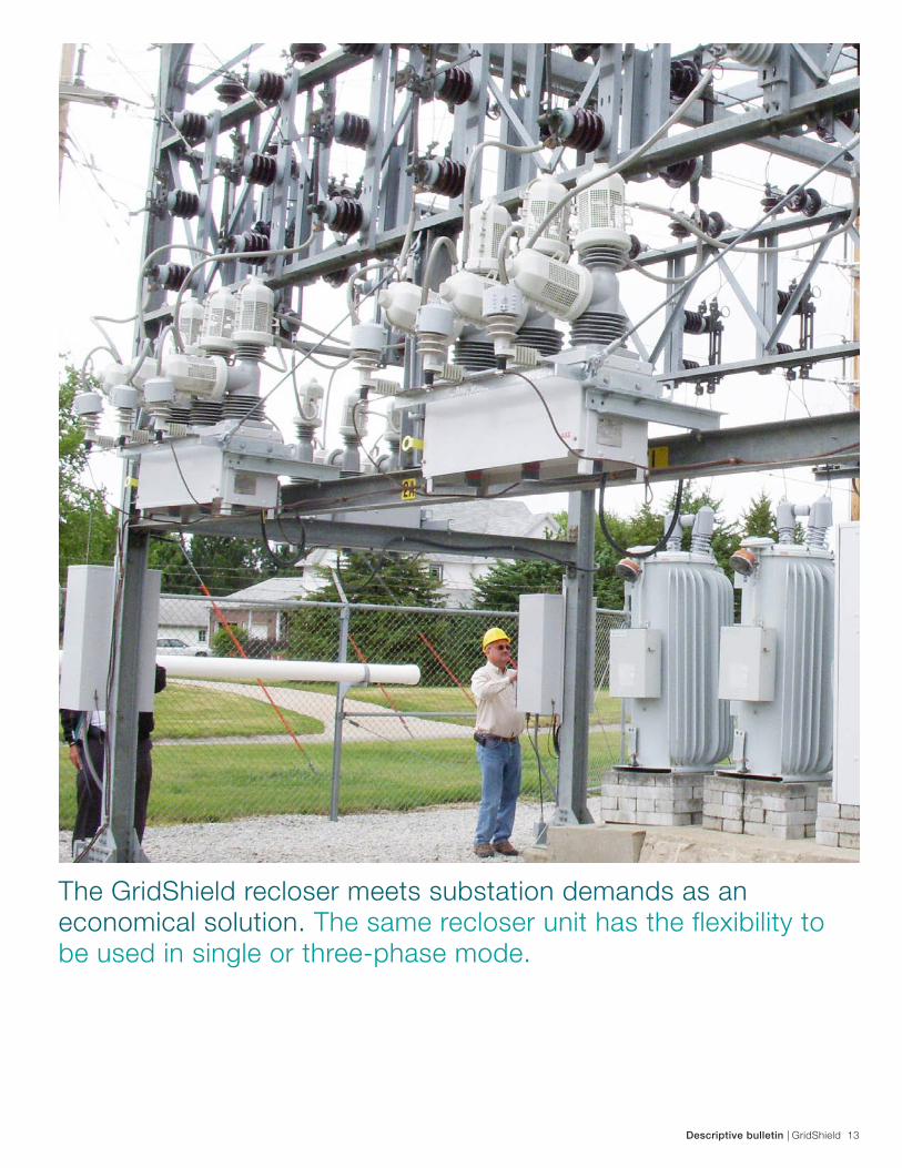
The GridShield recloser meets substation demands as an economical solution. The same recloser unit has the flexibility to be used in single or three-phase mode.
14 GridShield | Descriptive bulletin
Digit
1 2 3 4 5 6 7 8
S 1 1 8 1 C D E
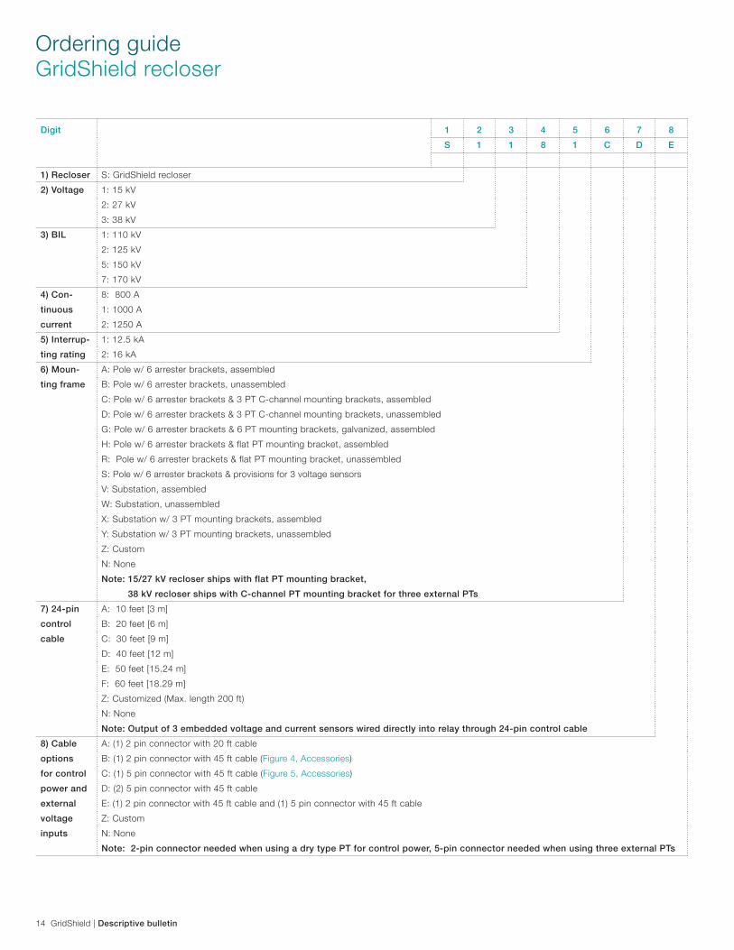
1) Recloser S: GridShield recloser
2) Voltage 1: 15 kV
2: 27 kV
3: 38 kV
3) BIL 1: 110 kV
2: 125 kV
5: 150 kV
7: 170 kV
4) Con-
tinuous
current
8: 800 A
1: 1000 A
2: 1250 A
5) Interrup-
ting rating
1: 12.5 kA
2: 16 kA
6) Moun-
ting frame
A: Pole w/ 6 arrester brackets, assembled
B: Pole w/ 6 arrester brackets, unassembled
C: Pole w/ 6 arrester brackets & 3 PT C-channel mounting brackets, assembled
D: Pole w/ 6 arrester brackets & 3 PT C-channel mounting brackets, unassembled
G: Pole w/ 6 arrester brackets & 6 PT mounting brackets, galvanized, assembled
H: Pole w/ 6 arrester brackets & flat PT mounting bracket, assembled
R: Pole w/ 6 arrester brackets & flat PT mounting bracket, unassembled
S: Pole w/ 6 arrester brackets & provisions for 3 voltage sensors
V: Substation, assembled
W: Substation, unassembled
X: Substation w/ 3 PT mounting brackets, assembled
Y: Substation w/ 3 PT mounting brackets, unassembled
Z: Custom
N: None
Note: 15/27 kV recloser ships with flat PT mounting bracket,
Note: 38 kV recloser ships with C-channel PT mounting bracket for three external PTs
7) 24-pin
control
cable
A: 10 feet [3 m]
B: 20 feet [6 m]
C: 30 feet [9 m]
D: 40 feet [12 m]
E: 50 feet [15.24 m]
F: 60 feet [18.29 m]
Z: Customized (Max. length 200 ft)
N: None
Note: Output of 3 embedded voltage and current sensors wired directly into relay through 24-pin control cable
8) Cable
options
for control
power and
external
voltage
inputs
A: (1) 2 pin connector with 20 ft cable
B: (1) 2 pin connector with 45 ft cable (Figure 4, Accessories)
C: (1) 5 pin connector with 45 ft cable (Figure 5, Accessories)
D: (2) 5 pin connector with 45 ft cable
E: (1) 2 pin connector with 45 ft cable and (1) 5 pin connector with 45 ft cable
Z: Custom
N: None
Note: 2-pin connector needed when using a dry type PT for control power,,5-pin connector needed when using three external PTs
Ordering guideGridShield recloser
Descriptive bulletin | GridShield 15
Digit
1 2 3 4 5 6 7 8
S 1 1 8 1 C D E
1) Recloser S: GridShield recloser
2) Voltage 1: 15 kV
2: 27 kV
3: 38 kV
3) BIL 1: 110 kV
2: 125 kV
5: 150 kV
7: 170 kV
4) Con-
tinuous
current
8: 800 A
1: 1000 A
2: 1250 A
5) Interrup-
ting rating
1: 12.5 kA
2: 16 kA
6) Moun-
ting frame
A: Pole w/ 6 arrester brackets, assembled
B: Pole w/ 6 arrester brackets, unassembled
C: Pole w/ 6 arrester brackets & 3 PT C-channel mounting brackets, assembled
D: Pole w/ 6 arrester brackets & 3 PT C-channel mounting brackets, unassembled
G: Pole w/ 6 arrester brackets & 6 PT mounting brackets, galvanized, assembled
H: Pole w/ 6 arrester brackets & flat PT mounting bracket, assembled
R: Pole w/ 6 arrester brackets & flat PT mounting bracket, unassembled
S: Pole w/ 6 arrester brackets & provisions for 3 voltage sensors
V: Substation, assembled
W: Substation, unassembled
X: Substation w/ 3 PT mounting brackets, assembled
Y: Substation w/ 3 PT mounting brackets, unassembled
Z: Custom
N: None
Note: 15/27 kV recloser ships with flat PT mounting bracket,
Note: 38 kV recloser ships with C-channel PT mounting bracket for three external PTs
7) 24-pin
control
cable
A: 10 feet [3 m]
B: 20 feet [6 m]
C: 30 feet [9 m]
D: 40 feet [12 m]
E: 50 feet [15.24 m]
F: 60 feet [18.29 m]
Z: Customized (Max. length 200 ft)
N: None
Note: Output of 3 embedded voltage and current sensors wired directly into relay through 24-pin control cable
8) Cable
options
for control
power and
external
voltage
inputs
A: (1) 2 pin connector with 20 ft cable
B: (1) 2 pin connector with 45 ft cable (Figure 4, Accessories)
C: (1) 5 pin connector with 45 ft cable (Figure 5, Accessories)
D: (2) 5 pin connector with 45 ft cable
E: (1) 2 pin connector with 45 ft cable and (1) 5 pin connector with 45 ft cable
Z: Custom
N: None
Note: 2-pin connector needed when using a dry type PT for control power,,5-pin connector needed when using three external PTs
Digit
9 10 11 12 13 14 15 16
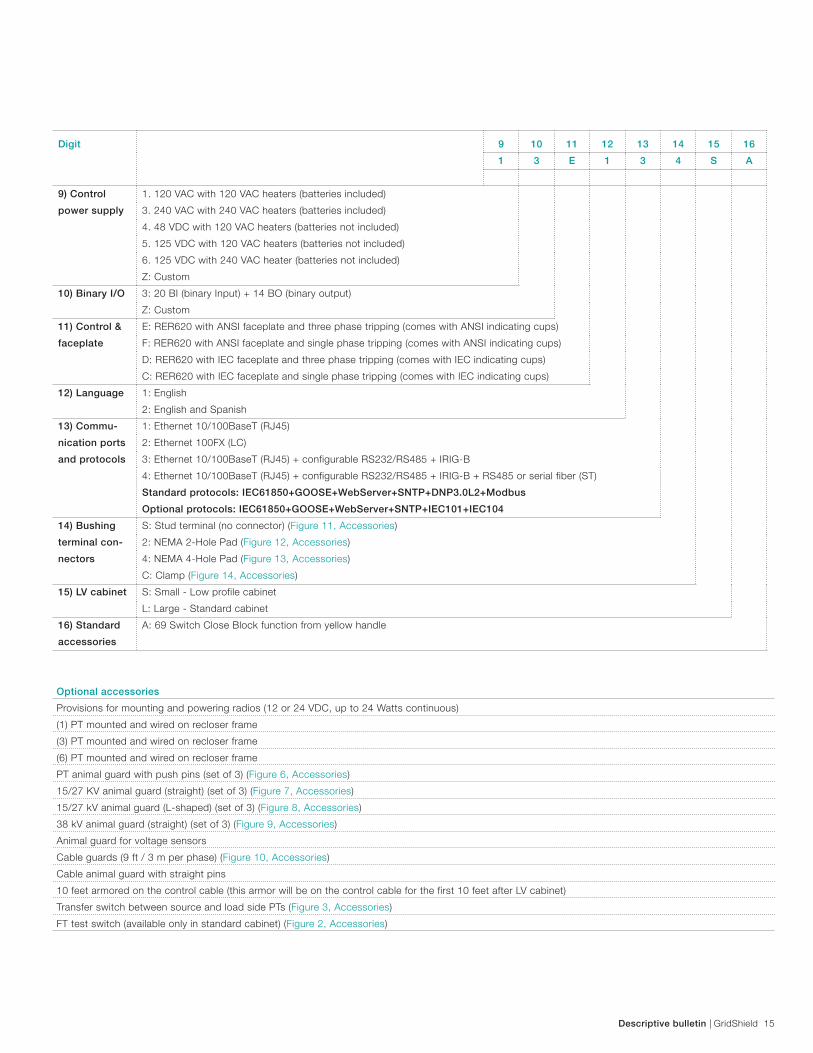
1 3 E 1 3 4 S A
9) Control
power supply
1. 120 VAC with 120 VAC heaters (batteries included)
3. 240 VAC with 240 VAC heaters (batteries included)
4. 48 VDC with 120 VAC heaters (batteries not included)
5. 125 VDC with 120 VAC heaters (batteries not included)
6. 125 VDC with 240 VAC heater (batteries not included)
Z: Custom
10) Binary I/O 3: 20 BI (binary Input) + 14 BO (binary output)
Z: Custom
11) Control &
faceplate
E: RER620 with ANSI faceplate and three phase tripping (comes with ANSI indicating cups)
F: RER620 with ANSI faceplate and single phase tripping (comes with ANSI indicating cups)
D: RER620 with IEC faceplate and three phase tripping (comes with IEC indicating cups)
C: RER620 with IEC faceplate and single phase tripping (comes with IEC indicating cups)
12) Language 1: English
2: English and Spanish
13) Commu-
nication ports
and protocols
1: Ethernet 10/100BaseT (RJ45)
2: Ethernet 100FX (LC)
3: Ethernet 10/100BaseT (RJ45) + configurable RS232/RS485 + IRIG-B
4: Ethernet 10/100BaseT (RJ45) + configurable RS232/RS485 + IRIG-B + RS485 or serial fiber (ST)
Standard protocols: IEC61850+GOOSE+WebServer+SNTP+DNP3.0L2+Modbus
Optional protocols: IEC61850+GOOSE+WebServer+SNTP+IEC101+IEC104
14) Bushing
terminal con-
nectors
S: Stud terminal (no connector) (Figure 11, Accessories)
2: NEMA 2-Hole Pad (Figure 12, Accessories)
4: NEMA 4-Hole Pad (Figure 13, Accessories)
C: Clamp (Figure 14, Accessories)
15) LV cabinet S: Small - Low profile cabinet
L: Large - Standard cabinet
16) Standard
accessories
A: 69 Switch Close Block function from yellow handle
Optional accessories
Provisions for mounting and powering radios (12 or 24 VDC, up to 24 Watts continuous)
(1) PT mounted and wired on recloser frame
(3) PT mounted and wired on recloser frame
(6) PT mounted and wired on recloser frame
PT animal guard with push pins (set of 3) (Figure 6, Accessories)
15/27 KV animal guard (straight) (set of 3) (Figure 7, Accessories)
15/27 kV animal guard (L-shaped) (set of 3) (Figure 8, Accessories)
38 kV animal guard (straight) (set of 3) (Figure 9, Accessories)
Animal guard for voltage sensors
Cable guards (9 ft / 3 m per phase) (Figure 10, Accessories)
Cable animal guard with straight pins
10 feet armored on the control cable (this armor will be on the control cable for the first 10 feet after LV cabinet)
Transfer switch between source and load side PTs (Figure 3, Accessories)
FT test switch (available only in standard cabinet) (Figure 2, Accessories)
16 GridShield | Descriptive bulletin
Digit
1 2 3 4 5 6 7 8 9 10
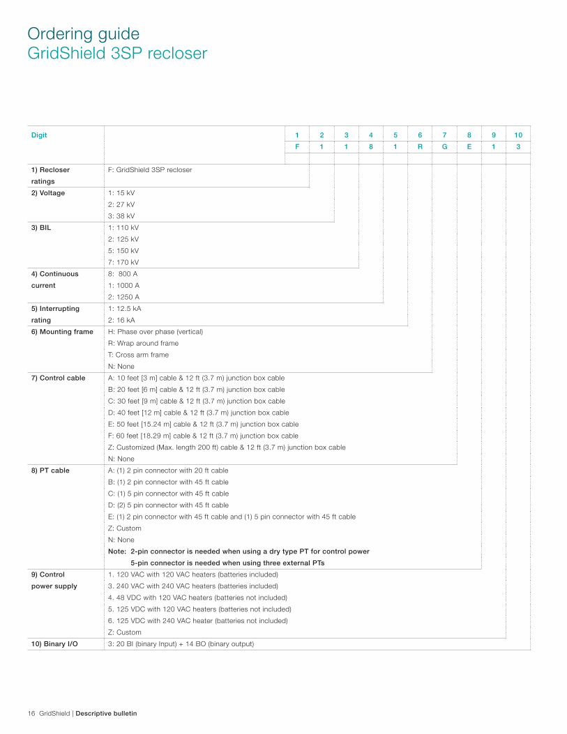
F 1 1 8 1 R G E 1 3
1) Recloser
ratings
F: GridShield 3SP recloser
2) Voltage 1: 15 kV
2: 27 kV
3: 38 kV
3) BIL 1: 110 kV
2: 125 kV
5: 150 kV
7: 170 kV
4) Continuous
current
8: 800 A
1: 1000 A
2: 1250 A
5) Interrupting
rating
1: 12.5 kA
2: 16 kA
6) Mounting frame H: Phase over phase (vertical)
R: Wrap around frame
T: Cross arm frame
N: None
7) Control cable A: 10 feet [3 m] cable & 12 ft (3.7 m) junction box cable
B: 20 feet [6 m] cable & 12 ft (3.7 m) junction box cable
C: 30 feet [9 m] cable & 12 ft (3.7 m) junction box cable
D: 40 feet [12 m] cable & 12 ft (3.7 m) junction box cable
E: 50 feet [15.24 m] cable & 12 ft (3.7 m) junction box cable
F: 60 feet [18.29 m] cable & 12 ft (3.7 m) junction box cable
Z: Customized (Max. length 200 ft) cable & 12 ft (3.7 m) junction box cable
N: None
8) PT cable A: (1) 2 pin connector with 20 ft cable
B: (1) 2 pin connector with 45 ft cable
C: (1) 5 pin connector with 45 ft cable
D: (2) 5 pin connector with 45 ft cable
E: (1) 2 pin connector with 45 ft cable and (1) 5 pin connector with 45 ft cable
Z: Custom
N: None
Note: 2-pin connector is needed when using a dry type PT for control power
Note: 5-pin connector is needed when using three external PTs
9) Control
power supply
1. 120 VAC with 120 VAC heaters (batteries included)
3. 240 VAC with 240 VAC heaters (batteries included)
4. 48 VDC with 120 VAC heaters (batteries not included)
5. 125 VDC with 120 VAC heaters (batteries not included)
6. 125 VDC with 240 VAC heater (batteries not included)
Z: Custom
10) Binary I/O 3: 20 BI (binary Input) + 14 BO (binary output)
Ordering guideGridShield 3SP recloser
Descriptive bulletin | GridShield 17
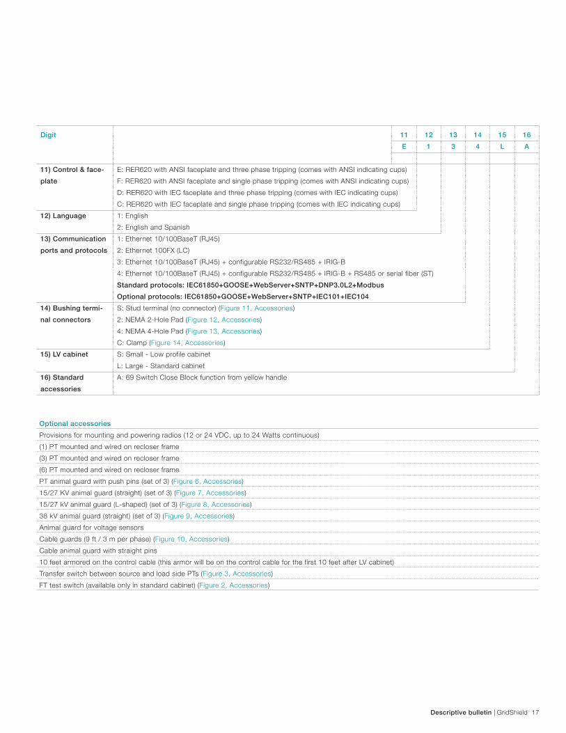
Optional accessories
Provisions for mounting and powering radios (12 or 24 VDC, up to 24 Watts continuous)
(1) PT mounted and wired on recloser frame
(3) PT mounted and wired on recloser frame
(6) PT mounted and wired on recloser frame
PT animal guard with push pins (set of 3) (Figure 6, Accessories)
15/27 KV animal guard (straight) (set of 3) (Figure 7, Accessories)
15/27 kV animal guard (L-shaped) (set of 3) (Figure 8, Accessories)
38 kV animal guard (straight) (set of 3) (Figure 9, Accessories)
Animal guard for voltage sensors
Cable guards (9 ft / 3 m per phase) (Figure 10, Accessories)
Cable animal guard with straight pins
10 feet armored on the control cable (this armor will be on the control cable for the first 10 feet after LV cabinet)
Transfer switch between source and load side PTs (Figure 3, Accessories)
FT test switch (available only in standard cabinet) (Figure 2, Accessories)
Digit
11 12 13 14 15 16
E 1 3 4 L A
11) Control & face-
plate
E: RER620 with ANSI faceplate and three phase tripping (comes with ANSI indicating cups)
F: RER620 with ANSI faceplate and single phase tripping (comes with ANSI indicating cups)
D: RER620 with IEC faceplate and three phase tripping (comes with IEC indicating cups)
C: RER620 with IEC faceplate and single phase tripping (comes with IEC indicating cups)
12) Language 1: English
2: English and Spanish
13) Communication
ports and protocols
1: Ethernet 10/100BaseT (RJ45)
2: Ethernet 100FX (LC)
3: Ethernet 10/100BaseT (RJ45) + configurable RS232/RS485 + IRIG-B
4: Ethernet 10/100BaseT (RJ45) + configurable RS232/RS485 + IRIG-B + RS485 or serial fiber (ST)
Standard protocols: IEC61850+GOOSE+WebServer+SNTP+DNP3.0L2+Modbus
Optional protocols: IEC61850+GOOSE+WebServer+SNTP+IEC101+IEC104
14) Bushing termi-
nal connectors
S: Stud terminal (no connector) (Figure 11, Accessories)
2: NEMA 2-Hole Pad (Figure 12, Accessories)
4: NEMA 4-Hole Pad (Figure 13, Accessories)
C: Clamp (Figure 14, Accessories)
15) LV cabinet S: Small - Low profile cabinet
L: Large - Standard cabinet
16) Standard
accessories
A: 69 Switch Close Block function from yellow handle
18 GridShield | Descriptive bulletin
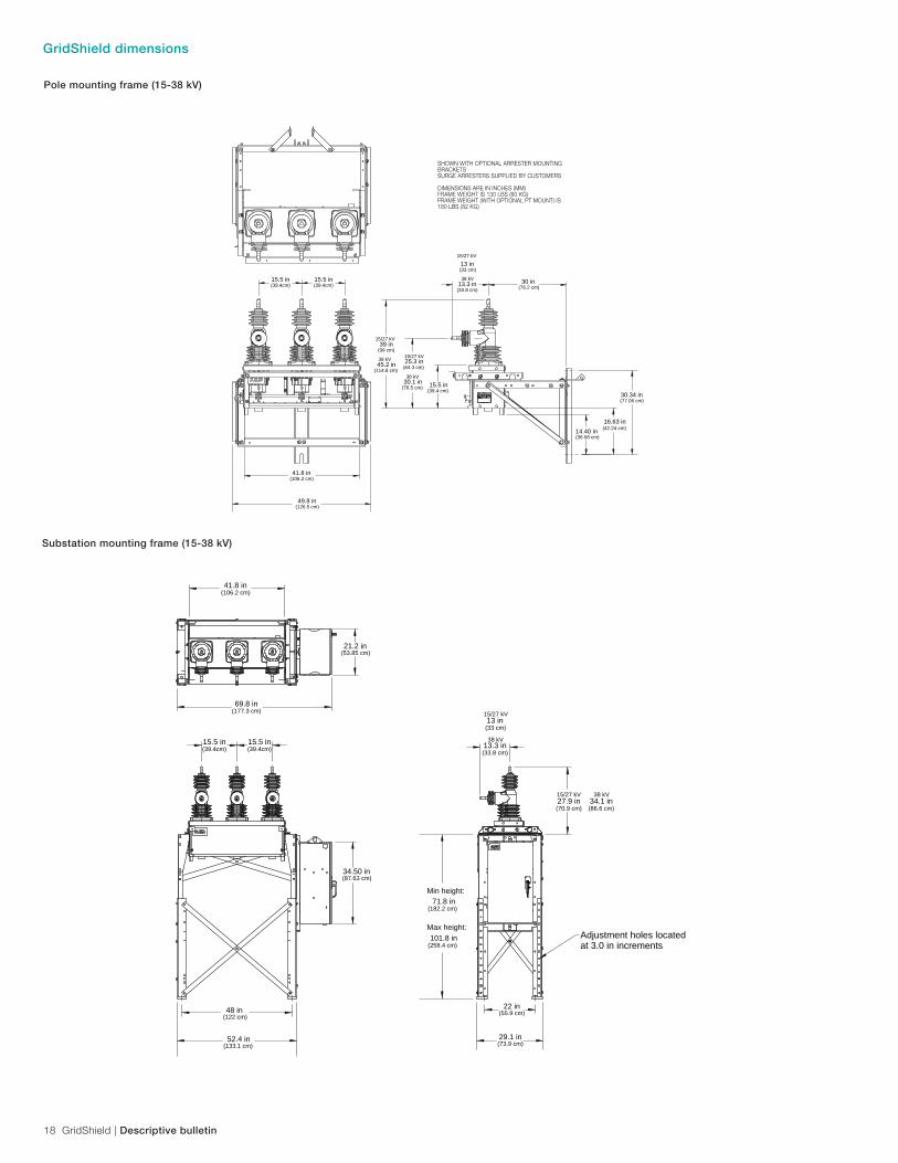
GridShield dimensions
Pole mounting frame (15-38 kV)
Adjustment holes located at 3.0 in increments
69.8 in
21.2 in (53.85 cm)
(177.3 cm)
34.50 in (87.63 cm)
48 in(122 cm)
22 in(55.9 cm)
29.1 in(73.9 cm)
52.4 in(133.1 cm)
41.8 in(106.2 cm)
15.5 in(39.4cm)
15.5 in(39.4cm)
13 in(33 cm)
15/27 kV
13.3 in(33.8 cm)
38 kV
27.9 in(70.9 cm)
15/27 kV
71.8 inMin height:
(182.2 cm)
101.8 inMax height:
(258.4 cm)
34.1 in(86.6 cm)
38 kV
30.34 in(77.06 cm)
30 in(76.2 cm)
13 in(33 cm)
15/27 kV
13.3 in(33.8 cm)
38 kV
15.5 in(39.4 cm)
25.3 in(64.3 cm)
15/27 kV
30.1 in(76.5 cm)
38 kV
39 in(99 cm)
15/27 kV
45.2 in(114.8 cm)
38 kV
15.5 in(39.4cm)
14.40 in(36.58 cm)
16.63 in(42.24 cm)
15.5 in(39.4cm)
49.8 in(126.5 cm)
41.8 in(106.2 cm)
SHOWN WITH OPTIONAL ARRESTER MOUNTING BRACKETSSURGE ARRESTERS SUPPLIED BY CUSTOMERS
DIMENSIONS ARE IN INCHES (MM)FRAME WEIGHT IS 130 LBS (60 KG)FRAME WEIGHT (WITH OPTIONAL PT MOUNT) IS 180 LBS (82 KG)
Substation mounting frame (15-38 kV)
Descriptive bulletin | GridShield 19
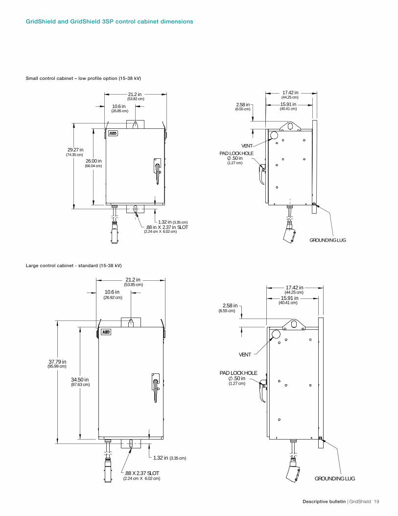
34.50 in (87.63 cm)
10.6 in(26.92 cm)
37.79 in(95.99 cm)
1.32 in (3.35 cm)
.88 X 2.37 SLOT
2.58 in
.50 in
17.42 in
15.91 in
PAD LOCK HOLE
VENT
(2.24 cm X 6.02 cm)
21.2 in (53.85 cm)
GROUNDING LUG
(6.55 cm)
(44.25 cm)
(40.41 cm)
(1.27 cm) 34.50 in (87.63 cm)
10.6 in(26.92 cm)
37.79 in(95.99 cm)
1.32 in (3.35 cm)
.88 X 2.37 SLOT
2.58 in
.50 in
17.42 in
15.91 in
PAD LOCK HOLE
VENT
(2.24 cm X 6.02 cm)
21.2 in (53.85 cm)
GROUNDING LUG
(6.55 cm)
(44.25 cm)
(40.41 cm)
(1.27 cm)
Large control cabinet - standard (15-38 kV)
Small control cabinet – low profile option (15-38 kV)
21.2 in (53.82 cm)
26.00 in (66.04 cm)
10.6 in (26.85 cm)
29.27 in (74.35 cm)
1.32 in (3.35 cm) .88 in X 2.37 in SLOT
(2.24 cm X 6.02 cm)
2.58 in (6.55 cm)
17.42 in (44.25 cm)
15.91 in (40.41 cm)
.50 in (1.27 cm)
PAD LOCK HOLE
VENT
GROUNDING LUG
GridShield and GridShield 3SP control cabinet dimensions
20 GridShield | Descriptive bulletin
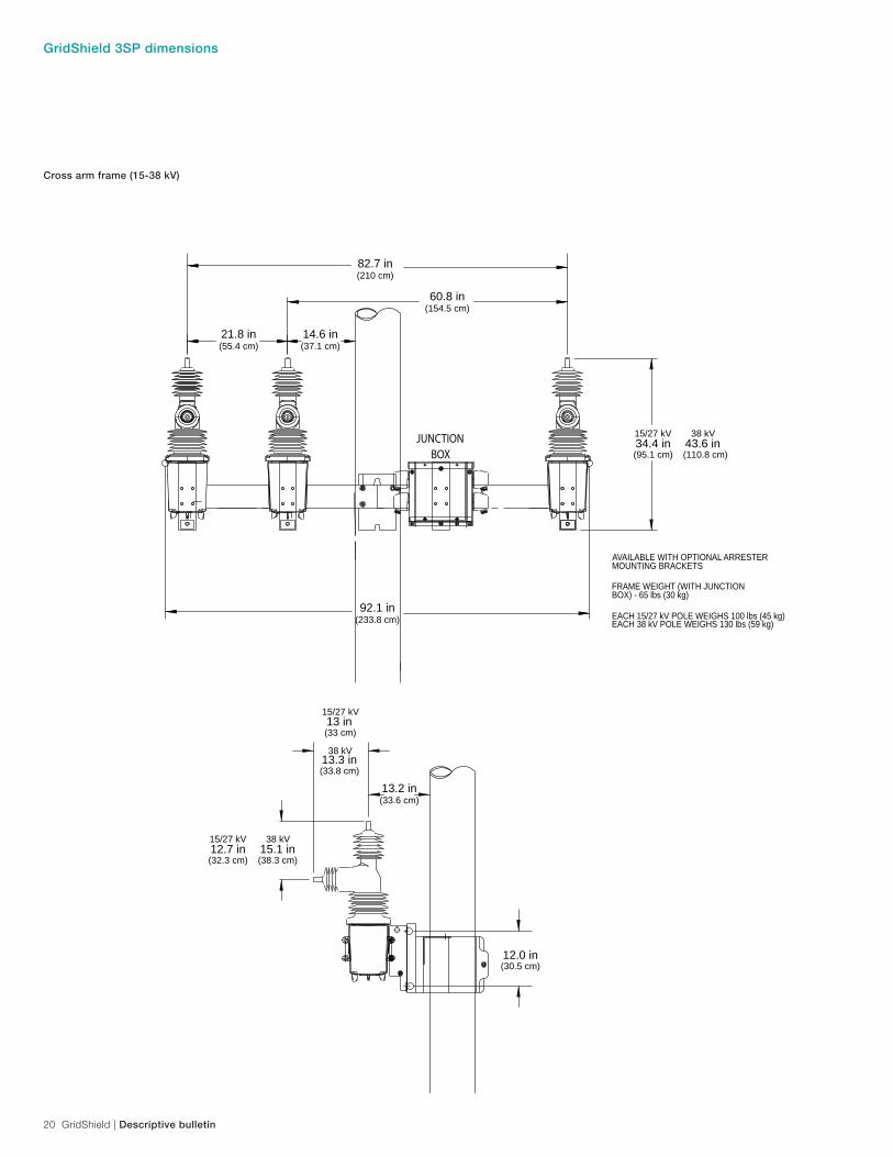
GridShield 3SP dimensions
JUNCTIONBOX
21.8 in(55.4 cm)
14.6 in(37.1 cm)
82.7 in(210 cm)
60.8 in(154.5 cm)
92.1 in(233.8 cm)
13.2 in(33.6 cm)
FRAME WEIGHT (WITH JUNCTION
EACH 15/27 kV POLE WEIGHS 100 lbs (45 kg)EACH 38 kV POLE WEIGHS 130 lbs (59 kg)
BOX) - 65 lbs (30 kg)
AVAILABLE WITH OPTIONAL ARRESTERMOUNTING BRACKETS
34.4 in(95.1 cm)
15/27 kV43.6 in(110.8 cm)
38 kV
13 in(33 cm)
15/27 kV
13.3 in(33.8 cm)
12.0 in(30.5 cm)
38 kV
12.7 in(32.3 cm)
15/27 kV15.1 in(38.3 cm)
38 kV
Cross arm frame (15-38 kV)
Descriptive bulletin | GridShield 21
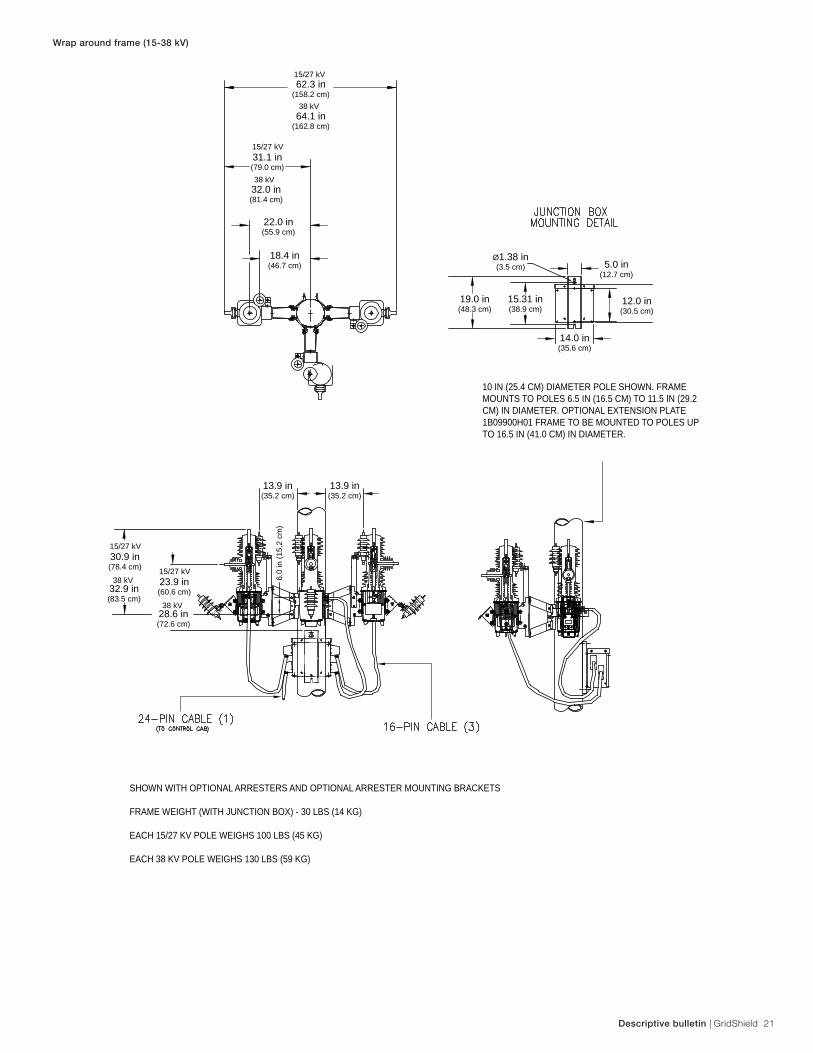
Wrap around frame (15-38 kV)
10 IN (25.4 CM) DIAMETER POLE SHOWN. FRAME MOUNTS TO POLES 6.5 IN (16.5 CM) TO 11.5 IN (29.2 CM) IN DIAMETER. OPTIONAL EXTENSION PLATE 1B09900H01 FRAME TO BE MOUNTED TO POLES UP TO 16.5 IN (41.0 CM) IN DIAMETER.
62.3 in(158.2 cm)
31.1 in(79.0 cm)
22.0 in(55.9 cm)
5.0 in(12.7 cm)
Ø1.38 in(3.5 cm)
12.0 in(30.5 cm)
19.0 in(48.3 cm)
15.31 in(38.9 cm)
14.0 in(35.6 cm)
18.4 in(46.7 cm)
13.9 in(35.2 cm)
6.0
in (1
5.2
cm)
13.9 in(35.2 cm)
15/27 kV
64.1 in(162.8 cm)
38 kV
32.0 in(81.4 cm)
38 kV
15/27 kV
32.9 in(83.5 cm)
38 kV
30.9 in(78.4 cm)
15/27 kV
28.6 in(72.6 cm)
38 kV
23.9 in(60.6 cm)
15/27 kV
SHOWN WITH OPTIONAL ARRESTERS AND OPTIONAL ARRESTER MOUNTING BRACKETS
FRAME WEIGHT (WITH JUNCTION BOX) - 30 LBS (14 KG)
EACH 15/27 KV POLE WEIGHS 100 LBS (45 KG)
EACH 38 KV POLE WEIGHS 130 LBS (59 KG)
22 GridShield | Descriptive bulletin
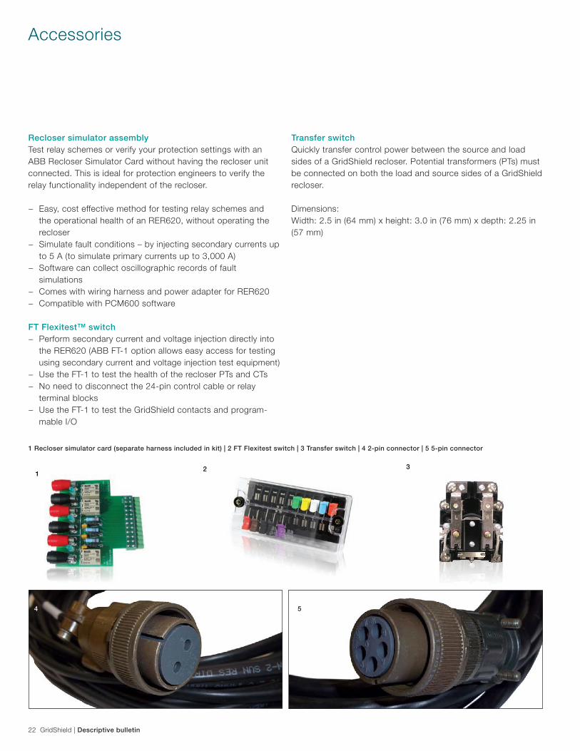
Accessories
Recloser simulator assemblyTest relay schemes or verify your protection settings with an ABB Recloser Simulator Card without having the recloser unit connected. This is ideal for protection engineers to verify the relay functionality independent of the recloser.
− Easy, cost effective method for testing relay schemes and the operational health of an RER620, without operating the recloser
− Simulate fault conditions – by injecting secondary currents up to 5 A (to simulate primary currents up to 3,000 A)
− Software can collect oscillographic records of fault simulations
− Comes with wiring harness and power adapter for RER620 − Compatible with PCM600 software
FT Flexitest™ switch − Perform secondary current and voltage injection directly into
the RER620 (ABB FT-1 option allows easy access for testing using secondary current and voltage injection test equipment)
− Use the FT-1 to test the health of the recloser PTs and CTs − No need to disconnect the 24-pin control cable or relay
terminal blocks − Use the FT-1 to test the GridShield contacts and program-
mable I/O
Transfer switchQuickly transfer control power between the source and load sides of a GridShield recloser. Potential transformers (PTs) must be connected on both the load and source sides of a GridShield recloser.
Dimensions:Width: 2.5 in (64 mm) x height: 3.0 in (76 mm) x depth: 2.25 in (57 mm)
1 Recloser simulator card (separate harness included in kit) | 2 FT Flexitest switch | 3 Transfer switch | 4 2-pin connector | 5 5-pin connector
2 31
4 5
Descriptive bulletin | GridShield 23
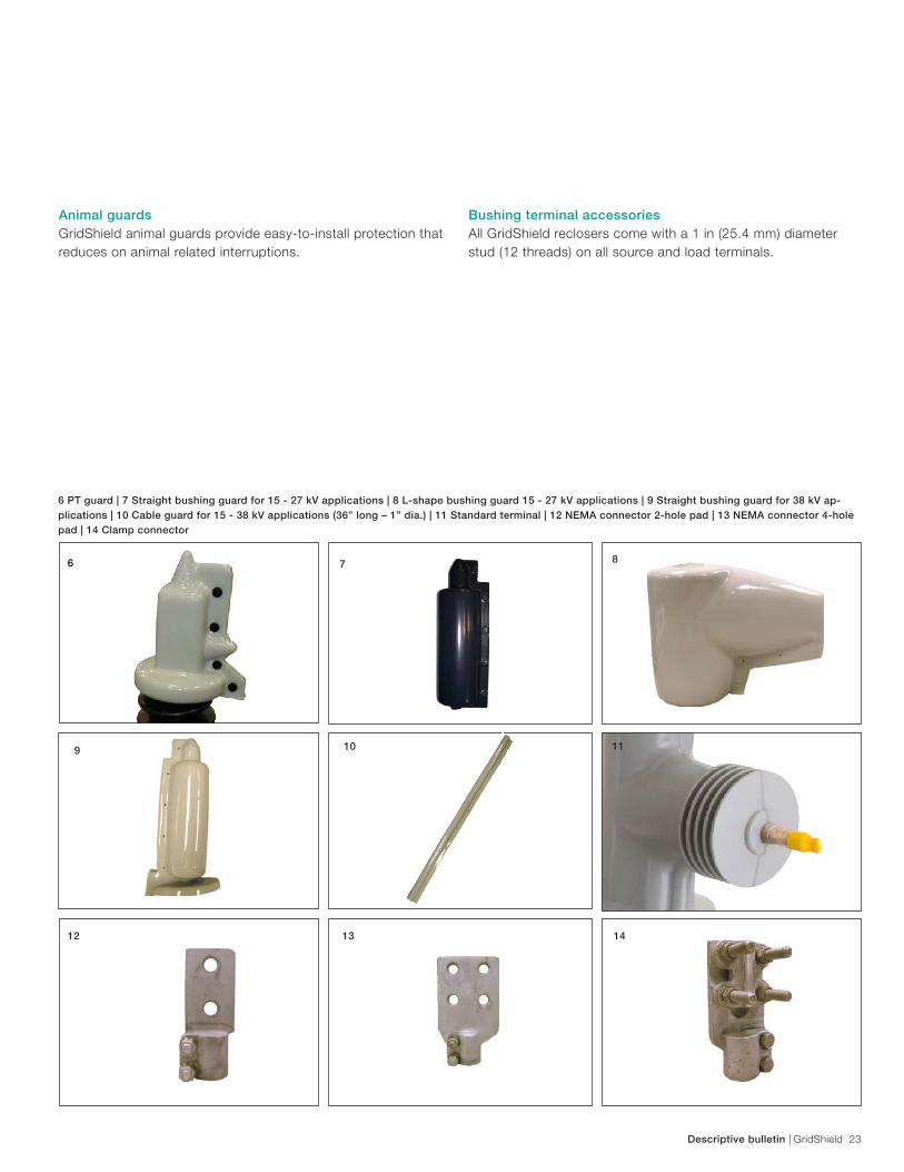
Animal guardsGridShield animal guards provide easy-to-install protection that reduces on animal related interruptions.
Bushing terminal accessoriesAll GridShield reclosers come with a 1 in (25.4 mm) diameter stud (12 threads) on all source and load terminals.
6 PT guard | 7 Straight bushing guard for 15 - 27 kV applications | 8 L-shape bushing guard 15 - 27 kV applications | 9 Straight bushing guard for 38 kV ap-plications | 10 Cable guard for 15 - 38 kV applications (36” long – 1” dia.) | 11 Standard terminal | 12 NEMA connector 2-hole pad | 13 NEMA connector 4-hole pad | 14 Clamp connector
7
119
12
8
13
10
14
6
24 GridShield | Descriptive bulletin
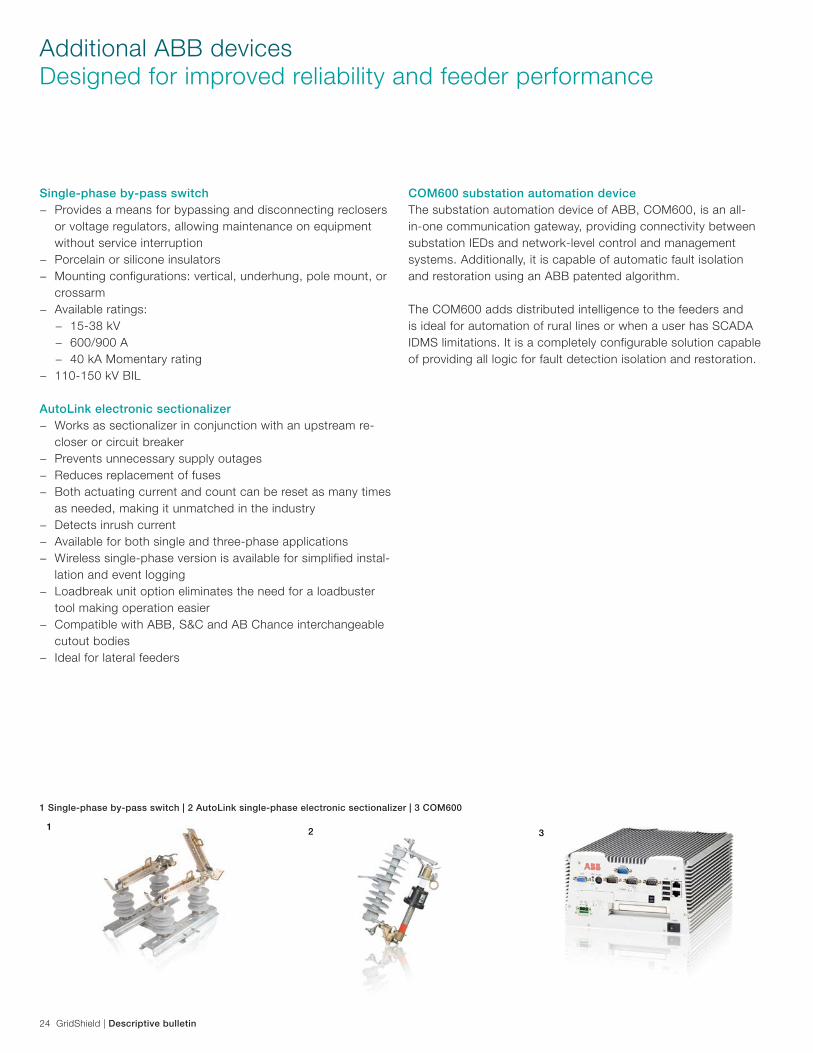
Additional ABB devicesDesigned for improved reliability and feeder performance
Single-phase by-pass switch − Provides a means for bypassing and disconnecting reclosers
or voltage regulators, allowing maintenance on equipment without service interruption
− Porcelain or silicone insulators − Mounting configurations: vertical, underhung, pole mount, or
crossarm − Available ratings:
− 15-38 kV − 600/900 A − 40 kA Momentary rating
− 110-150 kV BIL
AutoLink electronic sectionalizer − Works as sectionalizer in conjunction with an upstream re-
closer or circuit breaker − Prevents unnecessary supply outages − Reduces replacement of fuses − Both actuating current and count can be reset as many times
as needed, making it unmatched in the industry − Detects inrush current − Available for both single and three-phase applications − Wireless single-phase version is available for simplified instal-
lation and event logging − Loadbreak unit option eliminates the need for a loadbuster
tool making operation easier − Compatible with ABB, S&C and AB Chance interchangeable
cutout bodies − Ideal for lateral feeders
COM600 substation automation deviceThe substation automation device of ABB, COM600, is an all-in-one communication gateway, providing connectivity between substation IEDs and network-level control and management systems. Additionally, it is capable of automatic fault isolation and restoration using an ABB patented algorithm.
The COM600 adds distributed intelligence to the feeders and is ideal for automation of rural lines or when a user has SCADA IDMS limitations. It is a completely configurable solution capable of providing all logic for fault detection isolation and restoration.
1 Single-phase by-pass switch | 2 AutoLink single-phase electronic sectionalizer | 3 COM600
132

Descriptive bulletin | GridShield 25
Service & support
Product warranty − 3-year warranty on the recloser − 12-year warranty on the RER620 relay
Recloser customer support − Free 24/7 technical support line 1-800-929-7947 ext. 5 or
outside the U.S. +1 407-732-2000 ext. 2510, e-mail [email protected]
TrainingFactory based training: three-day training designed for partici-pants to become proficient in application, installation, operation, maintenance, testing, and commissioning of RER620 relays and GridShield reclosers.
Day 1 topics − GridShield with RER620 relay − GridShield recloser unit − GridShield control cabinet − RER620 relay − WebHMI operator interface − Protection and Control IED Manager, PCM600 tool
Day 2 topics − Graphical display editor − Parameter setting tool − Application configuration tool for logic programming − Recloser settings
Day 3 topics − DNP3 settings − Configuration management tool for point remapping − DNP3 objects, classes, events, deadbands, and variation − Feeder application using loop control, GOOSE messaging
with a mid-point, sectionalizing and normally open tie point recloser
Registration − Visit us on the web:
new.abb.com/medium-voltage/service/training/ − Click Scheduled classroom trainings − Click Recloser and recloser control training in Lake Mary, FL
USA (published training dates appear here) − Click Register now under GSR001
On-site training, commissioning assistance, and migration trainingOn-site training sessions are offered upon request and can be arranged at the customer facility. Arrangements may be made by contacting ABB in Lake Mary, Florida.
ABB can provide assistance during installation and commissio-ning of the recloser, including migration support for the develop-ment of relay settings and logic.
26 GridShield | Descriptive bulletin
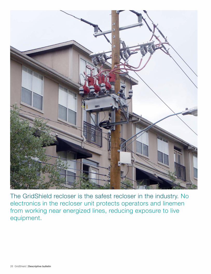
The GridShield recloser is the safest recloser in the industry. No electronics in the recloser unit protects operators and linemen from working near energized lines, reducing exposure to live equipment.

Descriptive bulletin | GridShield 27
Notes

Contact us
1VA
L245
401-
DB
Rev
E F
ebru
ary
2016ABB Inc.
655 Century Point Lake Mary, FL 32746Phone: +1 407 732 2000Customer service: +1 800 929 7947 ext. 5
+1 407 732 2000 ext. 2510E-Mail: [email protected]
www.abb.com/mediumvoltage
The information contained in this document is for general information purposes only. While ABB strives to keep the information up to date and correct, it makes no representations or warranties of any kind, express or implied, about the completeness, accuracy, reliability, suitability or availability with respect to the information, products, services, or related graphics contained in the document for any purpose. Any reliance placed on such informa-tion is therefore strictly at your own risk. ABB reserves the right to discontinue any product or service at any time.
© Copyright 2016 ABB. All rights reserved.