Embed Size (px)
Citation preview
Naval Surface Warfare Center
West Bethesda, MD 20817-5700 Carderock Division
NSWCCD – CISD - 2011/005 August 2011 Center for Innovation in Ship Design
Technical Report
Green Arctic Patrol Vessel
By W. Scott Weidle Parker Field Nick Buckley
NSW
CC
D –
CIS
D -
2011
/001
NSW
CC
D –
CIS
D -
2011
/005
: Gre
en A
rctic
Pat
rol V
esse
l
Naval Surface Warfare Center Carderock Division
Center for Innovation in Ship Oesign
Knowledge People
REPORT DOCUMEN TATION PAGE ,r:(.VJII App,1.:JV11tl
OMB No. 0704·0188
~~·.: .. ~+<'"~~':~.~;·:~~~~·:;:(l·;:rt': ':4~1~:t;.~ ~~~~~~:·;~d';¢::::.:;~~~oan::~ ~t ;:=,';!:~~d· (~~~:l~ ~~~;;~'f~.;.bu~d~~~;~:~)!t:~~n .. '~~~·~~~~:fl.;~!~~:'t~~~~ olof(•fot (Jl o~···· ••d••O:Iil''l) '$-OJOI)r,$1 .. ;• •$ I ( • ftiO:h." · " !J lh o; ' ""( b n . It} Oo:wo;,l' oo)o:tol (J i) r,lo;n~. \V;.t::;l'o '"'""' H r,;.oo:f<I'Ji'Jo'll;t $ So::o ¥11,.1~<;.., OO ro.:(:l ()ol! lo} to:. l!olo)n'lttllo(•l o.:~oii !•:•• S ~..., O.!ai(Jrh ,010-'•0 H!AI. 12:15 Jwtfiirtlo• Oa·.l'hl Hi;1' " '.Y. Suil• lliJ-1, /lciWIIJhHt. '\/A .Cl:102·"'302:, fWiiSP":N"4"'"15 lil1111.1l'.i 1:~ • . .v•il l 'li ltl91.0¥ill't$1f:fl dil~ ""V <1•1111 pt o>.iii·«~ -111 , • .,,, n~ P"'-' llhttll b;t t!.vbiil~ 19 any
pc11(11!y 101 kthl'a t9 Cil'lll~t( u 1l1 il C911~<11t l)n + I miOI'I'fl\l•iln rill •x~rHo'. 411ipl(!y il cun cnlyvti1140f'I'IH CQ!'Itrol •~"':-~;1 .
PLEASE DO NOT RETURN YOUil FOilM TO lliE ABOVE AOOI1ESS. 1 . REPORT OATE (00·MM·Yl'YY) I~- RFPORT TYPE 3. OATES COVFREO (Fro m · ToJ
05-08-2011 Fmal 05/Z3i20 11 . 07129f.l011 4. TITLE ANO SUBTITLE !)~. CONTRACT NUMSER
Green Arctic Potrol Vesse-l
5b. GRANT NUMBER
5C. PROGRAM ELEMENT NUMBER
G. AUTHORISI 5d . PRO.IECT NUMBER
W. Scott Wei<Ue Parker Field Nicholas Buckley 5e. T 1\Sk NUMBER
Sf. WORK UNIT NUMOER
7. PCRFORMING OROAN12 ATION NAME(S) ANO AOORES5(F31 8 . PERFORMING ORGANIZATION
Na,·al Sw·fuce Warfare Center REPORT NUMOER
Conlerock Division NS\VCCD-CISD-201 :1005 9500 MMHth.ur Bonle.vam West Beth,.da, MD 30817-5700 9 . SPONSORING/M ONITORING AGEN CY NAME(SJ ANO AOORESS(I~SJ 10. SPONSOH/MONITOH"S ACRONYMISI
Chief of Naval Research One Libeny Center 875 Not1h Rnndolph Str.Jet, 11. 6PONSOR/MONITOR"6 REPORT
Sujte 1425 NUMBERISI
Arlir.glon, Vi>. 22203-1995 12. DISTFIIBUTIONJAVAILABILilV ST AlEMENl
Approved for Public Release: Oislribulion Unlimiled
13. SUPPLBI'IENTI\RY NOTES
1 t1. A8STRA.CT
Arcric wnrm ing :s expecced to drive mcrest!;ed traffic through the Arctic region for touri!lm, rese.nrch, resource extr"nct ion and tran.~(Klrtati.on pt.rposes Understanding the US will hwe a st.ratee)c objecllve in the reg1on m 1.1-~e coming decade:\, the curr,,nt U.S Na\) (US!\) Ueet is uot desig.ue~l to meet the challenge:) of OtxJeti.ng .H t!Je Atctic eHV'll omueut. AILti..::jpatiJJg that ueed. the Otet:J t Arctic Patrol Vessel (GAPV) prcjcct was a summer intern p~ojo;:t in the Center fer lnn<wAtion in Ship Design (C!SD) at Naval Surface Viarfarc Center Cardcrock (NS\VCCD) during the. 3ummer of 2009, and is now in its third itc:ation
The project developed a concept of operations and de-cign !Or a USK .'\relic P.Jtrol Veesel capable of meeting current gap; ir. Arctic opet·~tional C~~pabili t)' The eoal ofthi~ report is to rle.; r.rioo thi5 "'~'l-~rld~signand hie.hJiglll•ome dtr.e high Jr.,· e) imr.ar.ts tho. Arctic env:r~-nml has en surface combatant design.
16. SU8JECllEiiMS
Arctic patrol, green tecmocl'g'l, mxironment, ship desig)l, CISD. fuel ceU
16. SECURITY CLASSIFICATION OF: 17 . LJMITA IIUN 01; 1U. NUMUEH
3. REPORT b.Ai!Sl KACl c. l HIS PAGt: 1\BSTRliCT OF I'AGtS
Uncl&--si fied Unclassified Unclass1lied UL 85
19•. NAME OF RESPONSIBLE PERSON
Steve Ouimette 19b. TELEPHONE NUMBER !J»CI'.JdC #r~ cctMI
(301) 227-4219 Stand.vd Form 296 (Rev. SJ98) r. u.;..il,~·ol 1;, JH{l Std. Z0$,10
Naval Surface Warfare Center Carderock Division
Green Arctic Patrol Vessel i
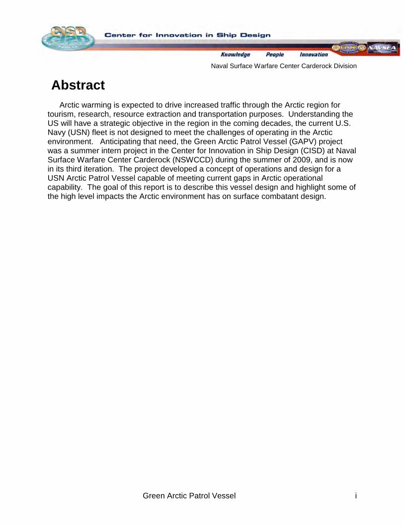
Abstract Arctic warming is expected to drive increased traffic through the Arctic region for
tourism, research, resource extraction and transportation purposes. Understanding the US will have a strategic objective in the region in the coming decades, the current U.S. Navy (USN) fleet is not designed to meet the challenges of operating in the Arctic environment. Anticipating that need, the Green Arctic Patrol Vessel (GAPV) project was a summer intern project in the Center for Innovation in Ship Design (CISD) at Naval Surface Warfare Center Carderock (NSWCCD) during the summer of 2009, and is now in its third iteration. The project developed a concept of operations and design for a USN Arctic Patrol Vessel capable of meeting current gaps in Arctic operational capability. The goal of this report is to describe this vessel design and highlight some of the high level impacts the Arctic environment has on surface combatant design.
Naval Surface Warfare Center Carderock Division
Green Arctic Patrol Vessel ii
Acknowledgements
The authors of this report would like to acknowledge and thank…
Livia Cohen NSWCCD 2202
LCDR Robert D’Eon NSWCCD 2202 (Canadian Navy Officer)
Michael Hughes SEAP
Steve Ouimette NSWCCD 2202
Dave Ruley NSWCCD 2202
Alan Shane NSWCCD 2202
Andy Tate NSWCCD 2202 (UKMOD Exchange Scientist)
Wesley Wilson NSWCCD 571
The team consisted of:
W. Scott Weidle
Naval Architect CISD
Nicholas Buckley
Mech. Engineering Penn. State
Parker Field
Ocean Engineering Virginia Tech
Naval Surface Warfare Center Carderock Division
Green Arctic Patrol Vessel iii
Table of Contents Abstract ....................................................................................................................... iAcknowledgements .....................................................................................................iiTable of Contents ....................................................................................................... iiiAcronyms .................................................................................................................. viiConcept Design Summary ....................................................................................... viii
1 Arctic Environment Considerations ...................................................................... 11.1 Background .............................................................................................. 11.2 Operational Environment .......................................................................... 51.3 Concept of Operations (CONOPS) ........................................................... 7
2 Design Process ................................................................................................... 92.1 Design Lanes and Requirements ............................................................. 92.2 Mission Systems .................................................................................... 102.3 Hull ......................................................................................................... 142.4 Topside Design ...................................................................................... 162.5 Hydrostatics ............................................................................................ 172.6 Open Water Power Requirements .......................................................... 192.7 Ice Class Power Requirements .............................................................. 212.8 Electrical Powering ................................................................................. 222.9 De-Icing .................................................................................................. 282.10 Waste Heat Recovery ............................................................................ 292.11 Electric Load Analysis ............................................................................ 292.12 Manning ................................................................................................. 302.13 Tankage and Subdivision ....................................................................... 312.14 Range Requirements ............................................................................. 322.15 Arrangements ......................................................................................... 342.16 Weights .................................................................................................. 362.17 Stability and Seakeeping ........................................................................ 39
3 Arctic Considerations and Green Initiatives ....................................................... 413.1 Alternative Power Systems .................................................................... 413.2 Coatings ................................................................................................. 42
Naval Surface Warfare Center Carderock Division
Green Arctic Patrol Vessel iv
3.3 Waste Management ............................................................................... 423.4 Ballast Water treatment: ......................................................................... 433.5 Materials ................................................................................................. 44
Conclusion ............................................................................................................... 45Recommendations for Future Work ......................................................................... 46References .............................................................................................................. 47Appendix A - GAPV Study Guide ............................................................................. 50Appendix B - Powering Curves at Other Drafts ........................................................ 53Appendix C - Environmental Conditions at Key Arctic Locations ............................. 55Appendix D - Ice Class Powering Calculations [17] ................................................... 57Appendix E - DG and SOFC Trade Study ................................................................ 59Appendix F - Manning Distribution ........................................................................... 62Appendix G – Electric Load Analysis ....................................................................... 63Appendix H - Arrangements ..................................................................................... 65Appendix I – SWBS Group: Two Digit Weight Breakdown ....................................... 68Appendix J - Stability Assessment ........................................................................... 70Appendix K – Materials ............................................................................................ 75
Naval Surface Warfare Center Carderock Division
Green Arctic Patrol Vessel v
Index of Figures Figure 1 - Arctic Geographic Region [1] ...................................................................... 1Figure 2 - Arctic Borders and Territory Claims [1] ....................................................... 2Figure 3 - Projected Minimum Summer Ice Extents [1] ............................................... 3Figure 4 - Current Arctic Traffic [4] .............................................................................. 3Figure 5 - Current USN Surface Operating Capability ............................................... 4Figure 6 – 2030 Projected Operational Areas and Distance to Port .......................... 5Figure 7 - KV Svalbard [6] ........................................................................................... 9Figure 8 – AOPS [7] .................................................................................................... 9Figure 9 – Thales Group IM 400 .............................................................................. 11Figure 10 - Canadian AOPS Lines ........................................................................... 15Figure 11 - GAPV Hullform Underbody .................................................................... 15Figure 12 – Topside Arrangement, Stern View ........................................................ 16Figure 13 - PARAMARINE GZ Stability Curve ......................................................... 17Figure 14 - POSSE Lightship Weight Distribution .................................................... 18Figure 15 - POSSE Draft vs. Displacement ............................................................. 18Figure 16 - POSSE Metacenter Height from Keel vs. Draft ..................................... 19Figure 17 - AOPS Brake Power Curve ..................................................................... 20Figure 18 – Effective, Shaft and Brake Power Required at 6.25 m Draft ................. 21Figure 19 - Channel Ice vs. Open Water Brake Power ............................................ 22Figure 20 - Azipod VI Power [19] ............................................................................... 23Figure 21 - IPS Arrangement for the GAPV ............................................................. 27Figure 22 - GAPV Manning Hierarchy ...................................................................... 31Figure 23 – Open Water and Channel Ice Range Combinations ............................. 34Figure 24 – Simplified GAPV Inboard Profile ........................................................... 35Figure 25 - Graphical Comparison of SWBS Weight Breakdown ............................. 38Figure 26 - Full Load Ice-Riding Condition ............................................................... 39Figure 27 - Draft: 5.75 m .......................................................................................... 53Figure 28 - Draft: 6.0 m ............................................................................................ 53Figure 29 - Draft: 6.5 m ............................................................................................ 54Figure 30 - Draft: 6.75 m .......................................................................................... 54Figure 31 - Trade Study Options Weight .................................................................. 59Figure 32 - Trade Study Options Total Volume ........................................................ 60Figure 33 - Trade Study Options Fuel Consumption per year .................................. 60Figure 34 - Trade Study Options Acquisition Cost ................................................... 61Figure 35 - Trade Study Options Life Cycle Cost ..................................................... 61Figure 36 - Full Load GZ Curve ............................................................................... 70Figure 37 - MinOp GZ Curve ................................................................................... 72
Naval Surface Warfare Center Carderock Division
Green Arctic Patrol Vessel vi
Index of Tables Table 1 - GAPV Extreme Operating Conditions ......................................................... 6Table 2 - Design Guidance Ship Particulars ............................................................ 10Table 3 - USN Sensors ............................................................................................ 11Table 4 - Off-board Vehicle Options ......................................................................... 13Table 5 - Autonomous Vehicles ............................................................................... 14Table 6 - PARAMARINE Hydrostatics Particulars .................................................... 17Table 7 - AOPS Principal Characteristics ................................................................ 19Table 8 - Breakdown of Propulsive Efficiencies, ...................................................... 20Table 9 - Fuel Cell Alternative Specifications ........................................................... 24Table 10 - Diesel Generator vs. Solid Oxide Fuel Cell ............................................. 25Table 11 - Propulsion Power Trade Study ............................................................... 26Table 12 - Simplified ELA and Auxiliary Loads ........................................................ 30Table 13 – Minimum Crew Numbers by Department ............................................... 30Table 14 – Available Tankage Volumes ................................................................... 32Table 15 - Range in Open Water, Channel Ice ........................................................ 33Table 16 - Seasonal Range Breakdown (nm) .......................................................... 33Table 17 - Area and Volume Requirements ............................................................. 34Table 18 - SWBS 1-Digit Weight Breakdown Comparison ....................................... 37Table 19 - Icing Survivability Data without De-Icing ................................................. 38Table 20 - Coating Types ......................................................................................... 42Table 21 - Solid Waste Generation .......................................................................... 43Table 22 - Non-Oily Waste ....................................................................................... 43Table 23 - Oily Waste .............................................................................................. 43Table 24 - Environment Conditions .......................................................................... 55Table 25 - Environmental Conditions Definitions ..................................................... 56Table 26 – Trade Study Options Legend ................................................................. 59Table 27 - Main Switchboard, High Voltage, 3 phase .............................................. 63Table 28 - Ship Service Switchboard, 440V, 3 phase .............................................. 64Table 29 - Full Load Tankage Values ...................................................................... 70Table 30 - Full Load with Icing Tankage Values ...................................................... 71Table 31 - MinOp Tankage Values .......................................................................... 72Table 32 - Full Load-Ice Riding Stability .................................................................. 73Table 33 - Full Load Icing-Ice Riding Stability .......................................................... 73Table 34 - Full Loading-Ice Riding with Ballast Adjustment ..................................... 74
Naval Surface Warfare Center Carderock Division
Green Arctic Patrol Vessel vii
Acronyms ABS – American Bureau of Shipping ABB - Asea Brown Boveri AOPS – Canadian Arctic Offshore Patrol Ship Design AMR – Auxiliary Machinery Room ASUW – Anti-Surface Warfare ASW – Anti-Submarine Warfare AUV – Autonomous Underwater Vehicle C4ISR – Command, Control, Communications, Computers, Intelligence, Surveillance and
Reconnaissance CFD – Computational Fluid Dynamics CISD – Center for Innovation in Ship Design CONOPS – Concept of Operations DDS – Design Data Sheet DFM – Diesel Fuel Marine DG – Diesel Generator DNV – Det Norske Veritas EEZ – Exclusive Economic Zone ELA – Electric Load Analysis EPA – Environmental Protection Agency GAPV – Green Arctic Patrol Vessel GM – Distance from Ship VCG to Transverse Metacenter IACS – International Association of Classification Societies IHDE – Integrated Hydrodynamic Design Environment IMO – International Maritime Organization IPS – Integrated Power System KM – Distance from Ship Keel to Transverse Metacenter MDA – Maritime Domain Awareness MMR – Main Machinery Room NATO – North Atlantic Treaty Organization NREIP – Naval Research Enterprise Internship Program NSWCCD – Naval Surface Warfare Center Carderock Division PZT – Piezoelectric Transducer RAM – Rolling Airframe Missile RANS – Reynolds Averaged Navier Stokes RHIB – Rigid Hull Inflatable Boat SAR – Search and Rescue SOFC – Solid Oxide Fuel Cell SS – Sea State STEP – System for Total Environmental Protection TEG – Thermoelectric Generator TSD – Total Ship Drag (CFD Software) UNCLOS – United Nations Convention on the Law of the Sea USCG – United States Coast Guard USN – United States Navy USV – Unmanned Surface Vehicle VCG, KG – Vertical Center of Gravity from Keel VTUAV – Vertical Takeoff Unmanned Aerial Vehicle
Naval Surface Warfare Center Carderock Division
Green Arctic Patrol Vessel viii
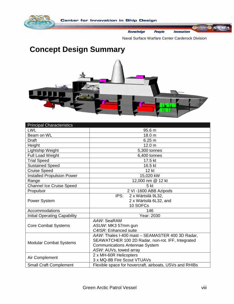
Concept Design Summary
Principal Characteristics LWL 95.6 m Beam on WL 18.0 m Draft 6.25 m Height 12.0 m Lightship Weight 5,300 tonnes Full Load Weight 6,400 tonnes Trial Speed 17.5 kt Sustained Speed 16.5 kt Cruise Speed 12 kt Installed Propulsion Power 15,020 kW Range 12,000 nm @ 12 kt Channel Ice Cruise Speed 5 kt Propulsor 2 VI -1600 ABB Azipods
Power System IPS: 2 x Wärtsilä 9L32,
2 x Wärtsilä 6L32, and 10 SOFCs
Accommodations 146 Initial Operating Capability Year: 2030
Core Combat Systems AAW: SeaRAM ASUW: MK3 57mm gun C4ISR: Enhanced suite
Modular Combat Systems
AAW: Thales I-400 mast – SEAMASTER 400 3D Radar, SEAWATCHER 100 2D Radar, non-rot. IFF, Integrated Communications Antennae System ASW: AUVs, towed array
Air Complement 2 x MH-60R Helicopters 3 x MQ-8B Fire Scout VTUAVs
Small Craft Complement Flexible space for hovercraft, airboats, USVs and RHIBs
Naval Surface Warfare Center Carderock Division
Green Arctic Patrol Vessel 1
1
1.1 Background
Arctic Environment Considerations
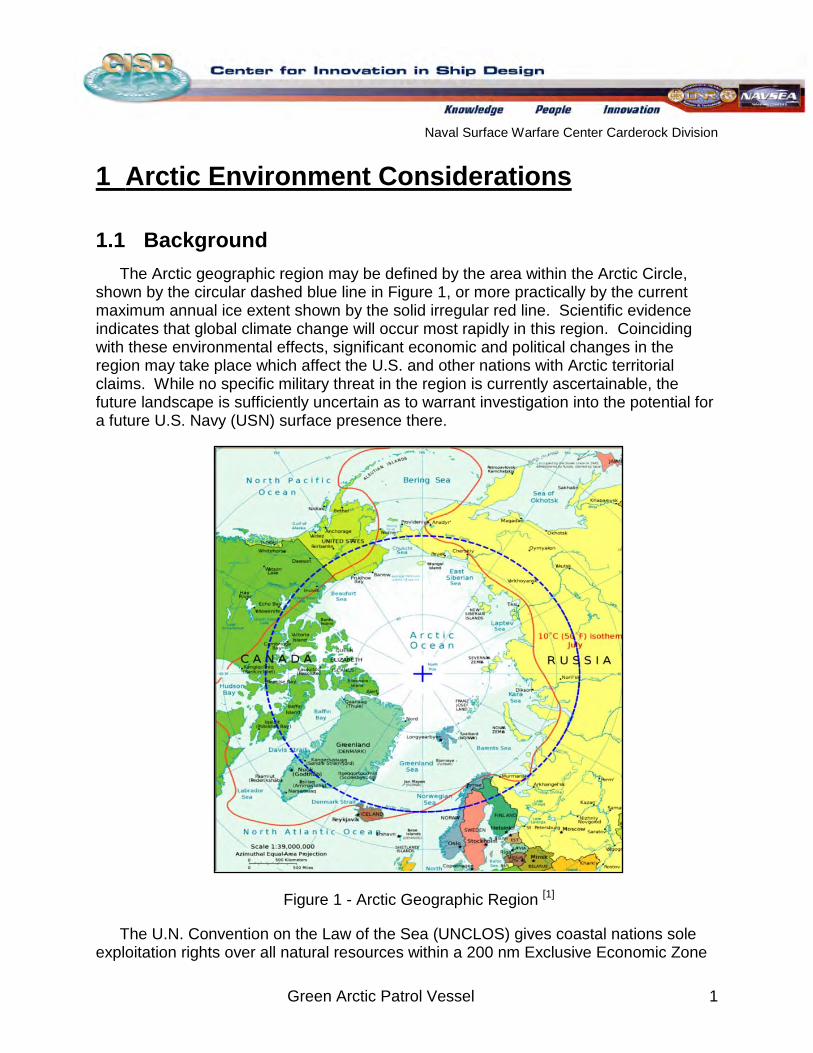
The Arctic geographic region may be defined by the area within the Arctic Circle, shown by the circular dashed blue line in Figure 1, or more practically by the current maximum annual ice extent shown by the solid irregular red line. Scientific evidence indicates that global climate change will occur most rapidly in this region. Coinciding with these environmental effects, significant economic and political changes in the region may take place which affect the U.S. and other nations with Arctic territorial claims. While no specific military threat in the region is currently ascertainable, the future landscape is sufficiently uncertain as to warrant investigation into the potential for a future U.S. Navy (USN) surface presence there.
Figure 1 - Arctic Geographic Region
The U.N. Convention on the Law of the Sea (UNCLOS) gives coastal nations sole exploitation rights over all natural resources within a 200 nm Exclusive Economic Zone
[1]
Naval Surface Warfare Center Carderock Division
Green Arctic Patrol Vessel 2
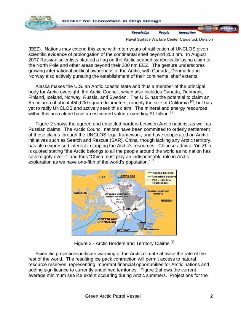
(EEZ). Nations may extend this zone within ten years of ratification of UNCLOS given scientific evidence of prolongation of the continental shelf beyond 200 nm. In August 2007 Russian scientists planted a flag on the Arctic seabed symbolically laying claim to the North Pole and other areas beyond their 200 nm EEZ. The gesture underscores growing international political awareness of the Arctic, with Canada, Denmark and Norway also actively pursuing the establishment of their continental shelf extents.
Alaska makes the U.S. an Arctic coastal state and thus a member of the principal body for Arctic oversight, the Arctic Council, which also includes Canada, Denmark, Finland, Iceland, Norway, Russia, and Sweden. The U.S. has the potential to claim an Arctic area of about 450,000 square kilometers, roughly the size of California [2], but has yet to ratify UNCLOS and actively seek this claim. The mineral and energy resources within this area alone have an estimated value exceeding $1 trillion 3[ ]
Figure 2 shows the agreed and unsettled borders between Arctic nations, as well as Russian claims. The Arctic Council nations have been committed to orderly settlement of these claims through the UNCLOS legal framework, and have cooperated on Arctic initiatives such as Search and Rescue (SAR). China, though lacking any Arctic territory, has also expressed interest in tapping the Arctic’s resources. Chinese admiral Yin Zhin is quoted stating “the Arctic belongs to all the people around the world as no nation has sovereignty over it” and thus “China must play an indispensable role in Arctic exploration as we have one-fifth of the world’s population.”
.
[4]
Figure 2 - Arctic Borders and Territory Claims
Scientific projections indicate warming of the Arctic climate at twice the rate of the rest of the world. The resulting ice pack contraction will permit access to natural resource reserves, representing important financial opportunities for Arctic nations and adding significance to currently undefined territories. Figure 2
[1]
shows the current average minimum sea ice extent occurring during Arctic summers. Projections for the
Naval Surface Warfare Center Carderock Division
Green Arctic Patrol Vessel 3
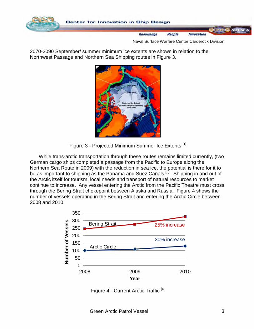
2070-2090 September/ summer minimum ice extents are shown in relation to the Northwest Passage and Northern Sea Shipping routes in Figure 3.
Figure 3 - Projected Minimum Summer Ice Extents
While trans-arctic transportation through these routes remains limited currently, (two German cargo ships completed a passage from the Pacific to Europe along the Northern Sea Route in 2009) with the reduction in sea ice, the potential is there for it to be as important to shipping as the Panama and Suez Canals
[1]
[2]
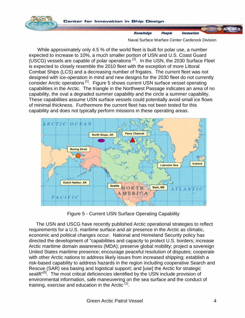
. Shipping in and out of the Arctic itself for tourism, local needs and transport of natural resources to market continue to increase. Any vessel entering the Arctic from the Pacific Theatre must cross through the Bering Strait chokepoint between Alaska and Russia. Figure 4 shows the number of vessels operating in the Bering Strait and entering the Arctic Circle between 2008 and 2010.
Figure 4 - Current Arctic Traffic [4]
0 50
100 150 200 250 300 350
2008 2009 2010
Num
ber o
f Ves
sels
Year
25% increase
30% increase
Bering Strait
Arctic Circle
Naval Surface Warfare Center Carderock Division
Green Arctic Patrol Vessel 4
While approximately only 4.5 % of the world fleet is built for polar use, a number expected to increase to 10%, a much smaller portion of USN and U.S. Coast Guard (USCG) vessels are capable of polar operations [2]. In the USN, the 2030 Surface Fleet is expected to closely resemble the 2010 fleet with the exception of more Littoral Combat Ships (LCS) and a decreasing number of frigates. The current fleet was not designed with ice-operation in mind and new designs for the 2030 fleet do not currently consider Arctic operations 1 [ ]
. Figure 5 shows current USN surface vessel operating capabilities in the Arctic. The triangle in the Northwest Passage indicates an area of no capability, the oval a degraded summer capability and the circle a summer capability. These capabilities assume USN surface vessels could potentially avoid small ice flows of minimal thickness. Furthermore the current fleet has not been tested for this capability and does not typically perform missions in these operating areas.
Figure 5 - Current USN Surface Operating Capability
The USN and USCG have recently published Arctic operational strategies to reflect requirements for a U.S. maritime surface and air presence in the Arctic as climatic, economic and political changes occur. National and Homeland Security policy has directed the development of “capabilities and capacity to protect U.S. borders; increase Arctic maritime domain awareness (MDA); preserve global mobility; project a sovereign United States maritime presence; encourage peaceful resolution of disputes; cooperate with other Arctic nations to address likely issues from increased shipping; establish a risk-based capability to address hazards in the region including cooperative Search and Rescue (SAR) sea basing and logistical support; and [use] the Arctic for strategic sealift”[5]. The most critical deficiencies identified by the USN include provision of environmental information, safe maneuvering on the sea surface and the conduct of training, exercise and education in the Arctic 1[ ].
Naval Surface Warfare Center Carderock Division
Green Arctic Patrol Vessel 5
The GAPV design seeks to fulfill, in part, these stated defense needs while meeting environmental impact goals using current projections for the 2030 physical, political and economic landscape as a design basis. Previous Arctic Patrol Vessel designs completed during 2009 and 2010 summer internships at the Center for Innovation in Ship Design (CISD) are reference points from which a new outlook is developed in the 2011 GAPV design. Comparable foreign designs such as the Canadian Arctic/ Offshore Patrol Ship (AOPS) and Norwegian KV Svalbard are also considered.
1.2 Operational Environment While all indications are for future Arctic warming, the region currently remains fully
or partially ice-covered for most of the year and will continue to be a harsh environment in the decades to come [1]
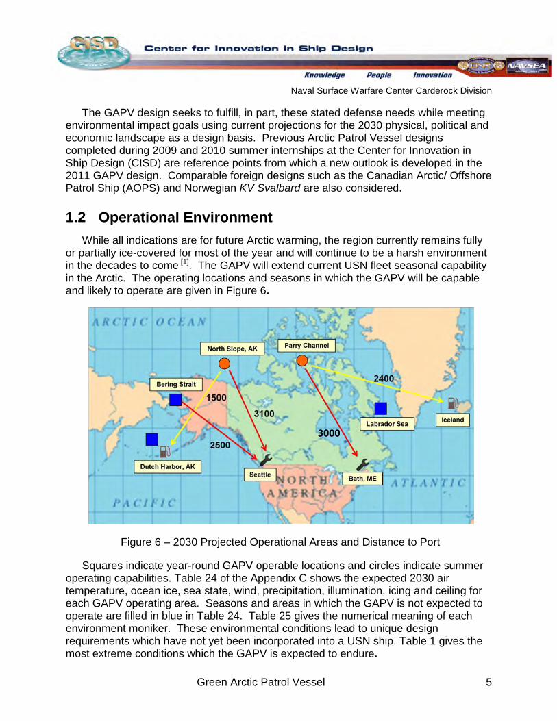
. The GAPV will extend current USN fleet seasonal capability in the Arctic. The operating locations and seasons in which the GAPV will be capable and likely to operate are given in Figure 6.
Figure 6 – 2030 Projected Operational Areas and Distance to Port
Squares indicate year-round GAPV operable locations and circles indicate summer operating capabilities. Table 24 of the Appendix C shows the expected 2030 air temperature, ocean ice, sea state, wind, precipitation, illumination, icing and ceiling for each GAPV operating area. Seasons and areas in which the GAPV is not expected to operate are filled in blue in Table 24. Table 25 gives the numerical meaning of each environment moniker. These environmental conditions lead to unique design requirements which have not yet been incorporated into a USN ship. Table 1 gives the most extreme conditions which the GAPV is expected to endure.
3000
Naval Surface Warfare Center Carderock Division
Green Arctic Patrol Vessel 6
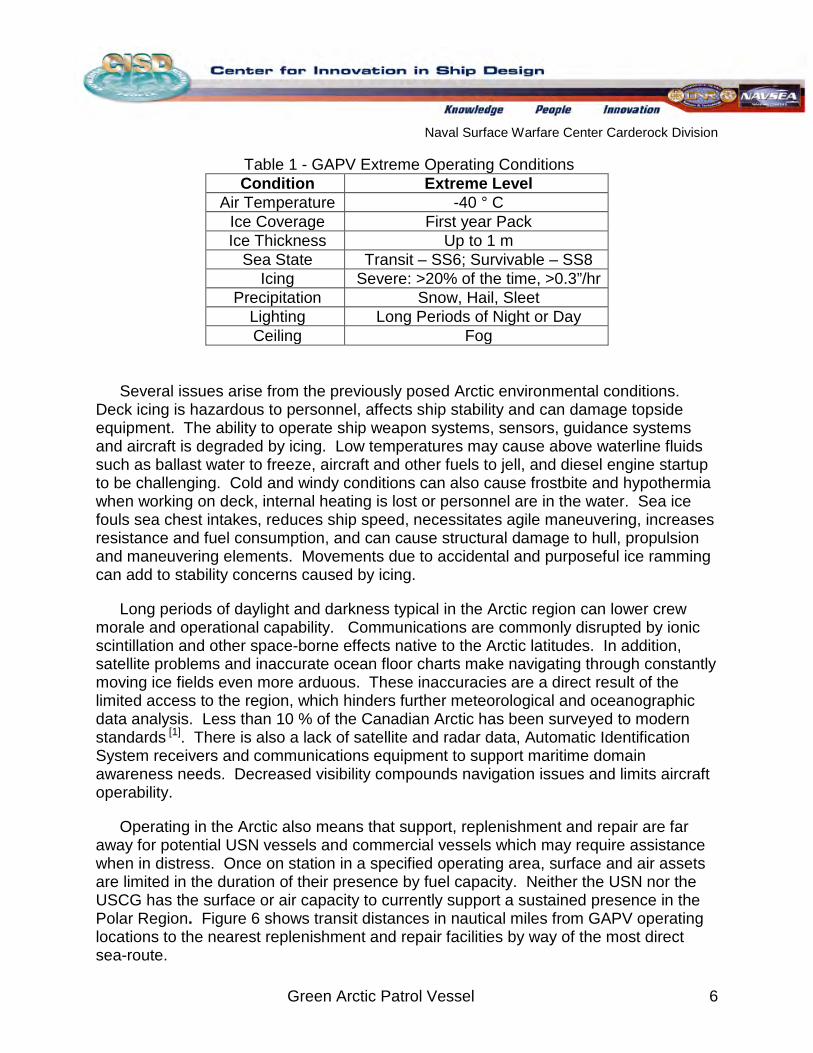
Table 1 - GAPV Extreme Operating Conditions
Several issues arise from the previously posed Arctic environmental conditions.
Deck icing is hazardous to personnel, affects ship stability and can damage topside equipment. The ability to operate ship weapon systems, sensors, guidance systems and aircraft is degraded by icing. Low temperatures may cause above waterline fluids such as ballast water to freeze, aircraft and other fuels to jell, and diesel engine startup to be challenging. Cold and windy conditions can also cause frostbite and hypothermia when working on deck, internal heating is lost or personnel are in the water. Sea ice fouls sea chest intakes, reduces ship speed, necessitates agile maneuvering, increases resistance and fuel consumption, and can cause structural damage to hull, propulsion and maneuvering elements. Movements due to accidental and purposeful ice ramming can add to stability concerns caused by icing.
Long periods of daylight and darkness typical in the Arctic region can lower crew morale and operational capability. Communications are commonly disrupted by ionic scintillation and other space-borne effects native to the Arctic latitudes. In addition, satellite problems and inaccurate ocean floor charts make navigating through constantly moving ice fields even more arduous. These inaccuracies are a direct result of the limited access to the region, which hinders further meteorological and oceanographic data analysis. Less than 10 % of the Canadian Arctic has been surveyed to modern standards [1]
Operating in the Arctic also means that support, replenishment and repair are far away for potential USN vessels and commercial vessels which may require assistance when in distress. Once on station in a specified operating area, surface and air assets are limited in the duration of their presence by fuel capacity. Neither the USN nor the USCG has the surface or air capacity to currently support a sustained presence in the Polar Region.
. There is also a lack of satellite and radar data, Automatic Identification System receivers and communications equipment to support maritime domain awareness needs. Decreased visibility compounds navigation issues and limits aircraft operability.
Figure 6 shows transit distances in nautical miles from GAPV operating locations to the nearest replenishment and repair facilities by way of the most direct sea-route.
Condition Extreme Level Air Temperature -40 ° C
Ice Coverage First year Pack Ice Thickness Up to 1 m
Sea State Transit – SS6; Survivable – SS8 Icing Severe: >20% of the time, >0.3”/hr
Precipitation Snow, Hail, Sleet Lighting Long Periods of Night or Day Ceiling Fog
Naval Surface Warfare Center Carderock Division
Green Arctic Patrol Vessel 7
The Arctic Ocean has a diverse ecosystem which is a sustaining economic force for many people in the region. Vessel pollution including solid waste release, exhaust emissions, overboard discharge and the spread of invasive species in ballast water and ship hulls can have devastating effects on marine life in the Arctic. Though the military is not necessarily bound by Environmental Protection Agency (EPA) or International Maritime Organization (IMO) regulations, protecting the region, public opinion and government accountability will drive compliance [1]
Further understanding of Arctic operating conditions and requirements will result from Arctic presence by the USN and support for scientific, commercial and USCG operations. The GAPV concept design is driven by Arctic environmental elements not typically necessary to consider for a surface combatant. Pollution, cold, ice, isolation and unfamiliarity are all considered at a high level in their impact on ship design and operation.
.
1.3 Concept of Operations (CONOPS) The GAPV will meet USN strategic Arctic objectives by contributing to safety,
stability, and security in the region, safeguarding U.S. maritime interests in the region, protecting U.S. citizens, infrastructure and resource interests, promoting and contributing to cooperative regional security relationships, and ensuring that USN forces are capable and ready [6]
Strategic Presence Humanitarian Assistance
. Current gaps in USN Arctic capability such as the ability to maneuver safely on the sea surface, gather environmental information and conduct training and exercise will be filled. Missions include:
Maritime Security Disaster Response Domain Awareness Defense Support of Civil Authorities Search and Rescue Environmental Survey Regional Security Cooperation Support Existing USCG Missions
The primary operational area will be the North Atlantic, Labrador Sea, Bering Sea and Bering Strait with seasonal operations in the North Slope and Northwest Passage as shown in Figure 6. The GAPV will meet International Association of Classification Societies (IACS) Polar Class 5 requirements and operate in medium first year ice up to one meter thick, which may contain old ice inclusions. Ice capabilities will be limited; however, mobility will be retained through enhanced maneuverability. The GAPV may operate in conjunction with another icebreaker vessel for access to areas of greater ice coverage. Reasonable effort will be made to ensure that the GAPV will meet foreseeable environmental standards in the Arctic by utilizing available and emerging “green” technologies.
The ship will be required to operate in remote areas and must be self-sustaining for mission durations of up to 120 days, allowing for continuous Arctic presence during the
Naval Surface Warfare Center Carderock Division
Green Arctic Patrol Vessel 8
summer months. The cruise speed will be at least 12 kt with an open water range no less than 12,000 nm. This range will be sufficient for transit between operational areas and ports shown in Figure 6 and increased fuel consumption during ice operations. Maximum sustained speed will be at least 17 kt with a goal of 20 kt. Because ice and/or high sea states will largely limit the GAPV’s ability to operate at its maximum speed, achieving high speeds is a secondary consideration.
The projected threat environment for the GAPV is limited to small-caliber arms fire, ramming and small boat attack. The GAPV will have a light gun armament for combating such threats, and anti-missile capability for self-defense. C4ISR systems will sufficiently transmit real-time information to/from other USN vessels and command, provide at-sea situational awareness and support maritime surface surveillance operations.
Hangar and support will be provided for up to two organic MH-60 helicopters and three MQ-8 Fire Scout VTUAVs. Aircraft launch and recovery operations shall persist through Sea State 3 (SS3). Flexible capability for a variety of organic craft, such as boat, hovercraft and/or Unmanned Underwater Vehicles (UUVs) will be included. The GAPV will be designed for initial operational capability in 2030.
Naval Surface Warfare Center Carderock Division
Green Arctic Patrol Vessel 9
2
2.1 Design Lanes and Requirements
Design Process
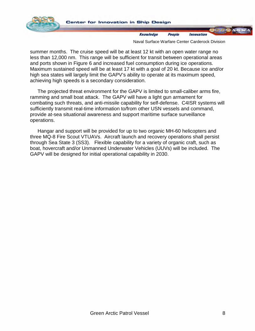
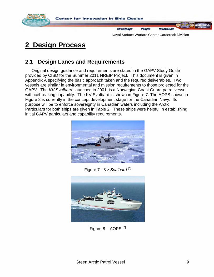
Original design guidance and requirements are stated in the GAPV Study Guide provided by CISD for the Summer 2011 NREIP Project. This document is given in Appendix A specifying the basic approach taken and the required deliverables. Two vessels are similar in environmental and mission requirements to those projected for the GAPV. The KV Svalbard, launched in 2001, is a Norwegian Coast Guard patrol vessel with icebreaking capability. The KV Svalbard is shown in Figure 7. The AOPS shown in Figure 8 is currently in the concept development stage for the Canadian Navy. Its purpose will be to enforce sovereignty in Canadian waters including the Arctic. Particulars for both ships are given in Table 2. These ships were helpful in establishing initial GAPV particulars and capability requirements.
Figure 7 - KV Svalbard
[6]
Figure 8 – AOPS [7]
Naval Surface Warfare Center Carderock Division
Green Arctic Patrol Vessel 10
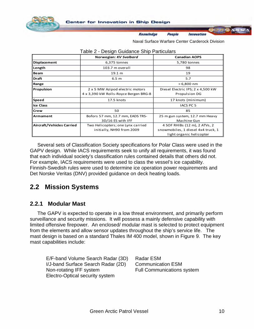
Table 2 - Design Guidance Ship Particulars
Norwegian: KV Svalbard Canadian AOPS
Displacement 6,375 tonnes 5,780 tonnes
Length 103.7 m overall 98
Beam 19.1 m 19
Draft 6.5 m 5.7
Range > 6,800 nm
Propulsion 2 x 5 MW Azipod electric motors4 x 3,390 kW Rolls-Royce Bergen BRG-8
DG
Diesel Electric IPS; 2 x 4,500 kW Propulsion DG
Speed 17.5 knots 17 knots (minimum)
Ice Class IACS PC 5
Crew 50 85
Armament Bofors 57 mm, 12.7 mm, EADS TRS-3D/16 ES with IFF
25 m gun system, 12.7 mm Heavy Machine Gun
Aircraft/Vehicles Carried Two Helicopters; one Lynx carried initially, NH90 from 2009
4 SOF RHIBs (12 m), 2 ATVs, 2 snowmobiles, 1 diesel 4x4 truck, 1
l ight organic helicopter
Several sets of Classification Society specifications for Polar Class were used in the GAPV design. While IACS requirements seek to unify all requirements, it was found that each individual society’s classification rules contained details that others did not. For example, IACS requirements were used to class the vessel’s ice capability. Finnish-Swedish rules were used to determine ice operation power requirements and Det Norske Veritas (DNV) provided guidance on deck heating loads.
2.2 Mission Systems
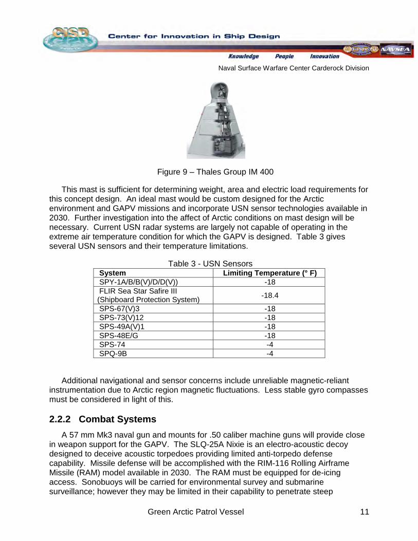
2.2.1 Modular Mast The GAPV is expected to operate in a low threat environment, and primarily perform
surveillance and security missions. It will possess a mainly defensive capability with limited offensive firepower. An enclosed/ modular mast is selected to protect equipment from the elements and allow sensor updates throughout the ship’s service life. The mast design is based on a standard Thales IM 400 model, shown in Figure 9. The key mast capabilities include:
E/F-band Volume Search Radar (3D) Radar ESM
Communication ESM Full Communications system
I/J-band Surface Search Radar (2D) Non-rotating IFF system Electro-Optical security system
Naval Surface Warfare Center Carderock Division
Green Arctic Patrol Vessel 11
Figure 9 – Thales Group IM 400
This mast is sufficient for determining weight, area and electric load requirements for this concept design. An ideal mast would be custom designed for the Arctic environment and GAPV missions and incorporate USN sensor technologies available in 2030. Further investigation into the affect of Arctic conditions on mast design will be necessary. Current USN radar systems are largely not capable of operating in the extreme air temperature condition for which the GAPV is designed. Table 3 gives several USN sensors and their temperature limitations.
Table 3 - USN Sensors System Limiting Temperature (° F) SPY-1A/B/B(V)/D/D(V)) -18 FLIR Sea Star Safire III (Shipboard Protection System) -18.4
SPS-67(V)3 -18 SPS-73(V)12 -18 SPS-49A(V)1 -18 SPS-48E/G -18 SPS-74 -4 SPQ-9B -4
Additional navigational and sensor concerns include unreliable magnetic-reliant instrumentation due to Arctic region magnetic fluctuations. Less stable gyro compasses must be considered in light of this.
2.2.2 Combat Systems A 57 mm Mk3 naval gun and mounts for .50 caliber machine guns will provide close
in weapon support for the GAPV. The SLQ-25A Nixie is an electro-acoustic decoy designed to deceive acoustic torpedoes providing limited anti-torpedo defense capability. Missile defense will be accomplished with the RIM-116 Rolling Airframe Missile (RAM) model available in 2030. The RAM must be equipped for de-icing access. Sonobuoys will be carried for environmental survey and submarine surveillance; however they may be limited in their capability to penetrate steep
Naval Surface Warfare Center Carderock Division
Green Arctic Patrol Vessel 12
thermoclines in the Arctic. A towed-array carried as a mission package and stored in a vehicle bay may be preferred as it can penetrate the thermoclines however, there are potential difficulties because of ship maneuvering restrictions while transiting, deploying and recovering the towed array.
2.2.3 Air Complement A robust organic air capability on the GAPV is essential to meet mission
requirements. This capability will include two MH-60 helicopters and three Fire Scout VTUAVs. The MH-60 is a multi-mission helicopter selected for its flexibility and adaptable functions. The primary functions of the MH-60 will be domain awareness/ surveillance, vertical replenishment and SAR/ MEDEVAC. The MH-60R variant may be embarked to enhance the GAPV’s anti-surface (ASUW) and anti-submarine (ASW) capability. Fire Scout VTUAV will expand the GAPV envelope of awareness while requiring less crew, fuel and space than a MH-60. The Fire Scout will perform surveillance and intelligence-related reconnaissance and contribute to maritime security, safety and protection of natural resources. The combination of three Fire Scouts and two MH-60s will provide a significant projection of force and a tool for awareness in the Arctic.
Despite their capabilities, air operations will be limited by environmental conditions. Launch and recovery operations are limited to SS3 and below due to ship motions. The MH-60 has both anti-ice and de-icing systems, permitting light-ice operations down to temperatures as low as -40° C [3]. However, temperatures less than -20° C may negatively affect the safety of Fire Scout operations, ground equipment and payload operations 1[ ]
. Cloud cover, low ceilings, ice fog and low visibility in the Arctic may also affect air operations.
Naval Surface Warfare Center Carderock Division
Green Arctic Patrol Vessel 13
2.2.4 Off-Board Vehicle Complement The USN does not currently possess an off-board vehicle capability in the Arctic, nor
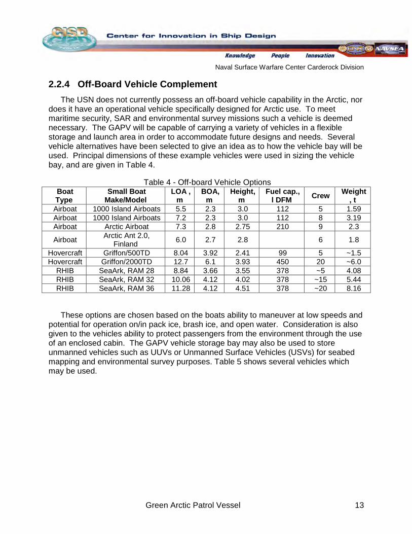
does it have an operational vehicle specifically designed for Arctic use. To meet maritime security, SAR and environmental survey missions such a vehicle is deemed necessary. The GAPV will be capable of carrying a variety of vehicles in a flexible storage and launch area in order to accommodate future designs and needs. Several vehicle alternatives have been selected to give an idea as to how the vehicle bay will be used. Principal dimensions of these example vehicles were used in sizing the vehicle bay, and are given in Table 4.
Table 4 - Off-board Vehicle Options Boat Type
Small Boat Make/Model
LOA , m
BOA, m
Height, m
Fuel cap., l DFM Crew Weight
, t Airboat 1000 Island Airboats 5.5 2.3 3.0 112 5 1.59 Airboat 1000 Island Airboats 7.2 2.3 3.0 112 8 3.19 Airboat Arctic Airboat 7.3 2.8 2.75 210 9 2.3 Airboat Arctic Ant 2.0,
Finland 6.0 2.7 2.8 6 1.8 Hovercraft Griffon/500TD 8.04 3.92 2.41 99 5 ~1.5 Hovercraft Griffon/2000TD 12.7 6.1 3.93 450 20 ~6.0
RHIB SeaArk, RAM 28 8.84 3.66 3.55 378 ~5 4.08 RHIB SeaArk, RAM 32 10.06 4.12 4.02 378 ~15 5.44 RHIB SeaArk, RAM 36 11.28 4.12 4.51 378 ~20 8.16
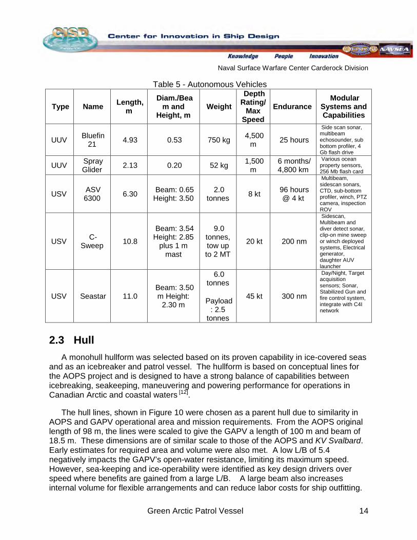
These options are chosen based on the boats ability to maneuver at low speeds and potential for operation on/in pack ice, brash ice, and open water. Consideration is also given to the vehicles ability to protect passengers from the environment through the use of an enclosed cabin. The GAPV vehicle storage bay may also be used to store unmanned vehicles such as UUVs or Unmanned Surface Vehicles (USVs) for seabed mapping and environmental survey purposes. Table 5 shows several vehicles which may be used.
Naval Surface Warfare Center Carderock Division
Green Arctic Patrol Vessel 14
Table 5 - Autonomous Vehicles
Type Name Length, m
Diam./Beam and
Height, m Weight
Depth Rating/
Max Speed
Endurance Modular
Systems and Capabilities
UUV Bluefin 21 4.93 0.53 750 kg 4,500
m 25 hours Side scan sonar, multibeam echosounder, sub bottom profiler, 4 Gb flash drive
UUV Spray Glider 2.13 0.20 52 kg 1,500
m 6 months/ 4,800 km
Various ocean property sensors, 256 Mb flash card
USV ASV 6300 6.30 Beam: 0.65
Height: 3.50 2.0
tonnes 8 kt 96 hours @ 4 kt
Multibeam, sidescan sonars, CTD, sub-bottom profiler, winch, PTZ camera, inspection ROV
USV C-Sweep 10.8
Beam: 3.54 Height: 2.85
plus 1 m mast
9.0 tonnes, tow up to 2 MT
20 kt 200 nm
Sidescan, Multibeam and diver detect sonar, clip-on mine sweep or winch deployed systems, Electrical generator, daughter AUV launcher
USV Seastar 11.0 Beam: 3.50
m Height: 2.30 m
6.0 tonnes
Payload
: 2.5 tonnes
45 kt 300 nm
Day/Night, Target acquisition sensors; Sonar, Stabilized Gun and fire control system, integrate with C4I network
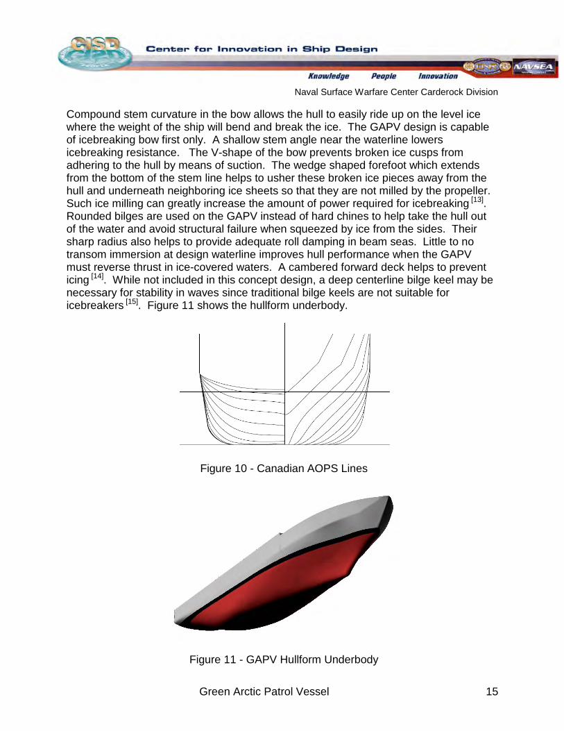
2.3 Hull A monohull hullform was selected based on its proven capability in ice-covered seas
and as an icebreaker and patrol vessel. The hullform is based on conceptual lines for the AOPS project and is designed to have a strong balance of capabilities between icebreaking, seakeeping, maneuvering and powering performance for operations in Canadian Arctic and coastal waters [12]
The hull lines, shown in
.
Figure 10 were chosen as a parent hull due to similarity in AOPS and GAPV operational area and mission requirements. From the AOPS original length of 98 m, the lines were scaled to give the GAPV a length of 100 m and beam of 18.5 m. These dimensions are of similar scale to those of the AOPS and KV Svalbard. Early estimates for required area and volume were also met. A low L/B of 5.4 negatively impacts the GAPV’s open-water resistance, limiting its maximum speed. However, sea-keeping and ice-operability were identified as key design drivers over speed where benefits are gained from a large L/B. A large beam also increases internal volume for flexible arrangements and can reduce labor costs for ship outfitting.
Naval Surface Warfare Center Carderock Division
Green Arctic Patrol Vessel 15
Compound stem curvature in the bow allows the hull to easily ride up on the level ice where the weight of the ship will bend and break the ice. The GAPV design is capable of icebreaking bow first only. A shallow stem angle near the waterline lowers icebreaking resistance. The V-shape of the bow prevents broken ice cusps from adhering to the hull by means of suction. The wedge shaped forefoot which extends from the bottom of the stem line helps to usher these broken ice pieces away from the hull and underneath neighboring ice sheets so that they are not milled by the propeller. Such ice milling can greatly increase the amount of power required for icebreaking [13]. Rounded bilges are used on the GAPV instead of hard chines to help take the hull out of the water and avoid structural failure when squeezed by ice from the sides. Their sharp radius also helps to provide adequate roll damping in beam seas. Little to no transom immersion at design waterline improves hull performance when the GAPV must reverse thrust in ice-covered waters. A cambered forward deck helps to prevent icing 14 [ ]. While not included in this concept design, a deep centerline bilge keel may be necessary for stability in waves since traditional bilge keels are not suitable for icebreakers 15 [ ]
. Figure 11 shows the hullform underbody.
Figure 10 - Canadian AOPS Lines
Figure 11 - GAPV Hullform Underbody
Naval Surface Warfare Center Carderock Division
Green Arctic Patrol Vessel 16
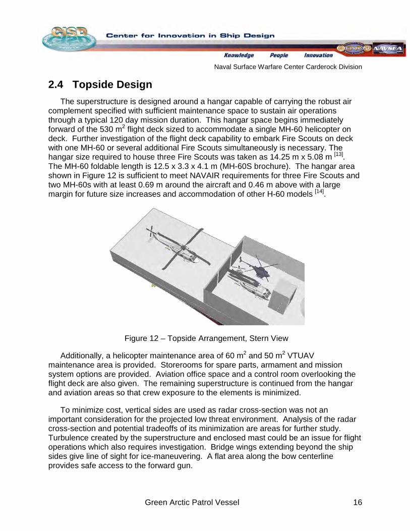
2.4 Topside Design The superstructure is designed around a hangar capable of carrying the robust air
complement specified with sufficient maintenance space to sustain air operations through a typical 120 day mission duration. This hangar space begins immediately forward of the 530 m2 flight deck sized to accommodate a single MH-60 helicopter on deck. Further investigation of the flight deck capability to embark Fire Scouts on deck with one MH-60 or several additional Fire Scouts simultaneously is necessary. The hangar size required to house three Fire Scouts was taken as 14.25 m x 5.08 m [13]. The MH-60 foldable length is 12.5 x 3.3 x 4.1 m (MH-60S brochure). The hangar area shown in Figure 12 is sufficient to meet NAVAIR requirements for three Fire Scouts and two MH-60s with at least 0.69 m around the aircraft and 0.46 m above with a large margin for future size increases and accommodation of other H-60 models [14]
.
Figure 12 – Topside Arrangement, Stern View
Additionally, a helicopter maintenance area of 60 m2 and 50 m2 VTUAV maintenance area is provided. Storerooms for spare parts, armament and mission system options are provided. Aviation office space and a control room overlooking the flight deck are also given. The remaining superstructure is continued from the hangar and aviation areas so that crew exposure to the elements is minimized.
To minimize cost, vertical sides are used as radar cross-section was not an important consideration for the projected low threat environment. Analysis of the radar cross-section and potential tradeoffs of its minimization are areas for further study. Turbulence created by the superstructure and enclosed mast could be an issue for flight operations which also requires investigation. Bridge wings extending beyond the ship sides give line of sight for ice-maneuvering. A flat area along the bow centerline provides safe access to the forward gun.
Naval Surface Warfare Center Carderock Division
Green Arctic Patrol Vessel 17
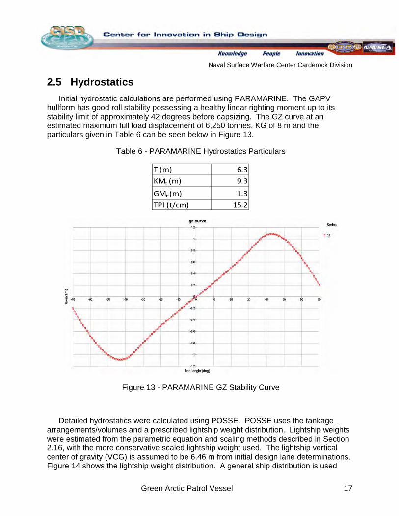
2.5 Hydrostatics Initial hydrostatic calculations are performed using PARAMARINE. The GAPV
hullform has good roll stability possessing a healthy linear righting moment up to its stability limit of approximately 42 degrees before capsizing. The GZ curve at an estimated maximum full load displacement of 6,250 tonnes, KG of 8 m and the particulars given in Table 6 can be seen below in Figure 13.
Table 6 - PARAMARINE Hydrostatics Particulars
T (m) 6.3
KMt (m) 9.3
GMt (m) 1.3
TPI (t/cm) 15.2
Figure 13 - PARAMARINE GZ Stability Curve
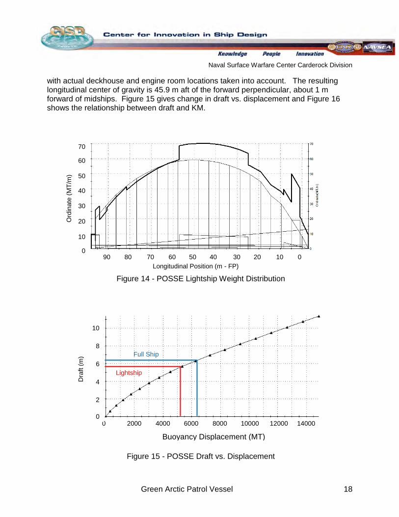
Detailed hydrostatics were calculated using POSSE. POSSE uses the tankage arrangements/volumes and a prescribed lightship weight distribution. Lightship weights were estimated from the parametric equation and scaling methods described in Section 2.16, with the more conservative scaled lightship weight used. The lightship vertical center of gravity (VCG) is assumed to be 6.46 m from initial design lane determinations. Figure 14 shows the lightship weight distribution. A general ship distribution is used
Naval Surface Warfare Center Carderock Division
Green Arctic Patrol Vessel 18
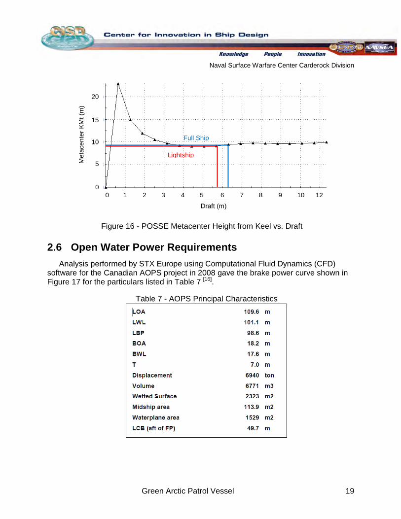
with actual deckhouse and engine room locations taken into account. The resulting longitudinal center of gravity is 45.9 m aft of the forward perpendicular, about 1 m forward of midships. Figure 15 gives change in draft vs. displacement and Figure 16 shows the relationship between draft and KM.
Figure 14 - POSSE Lightship Weight Distribution
Figure 15 - POSSE Draft vs. Displacement
Ord
inat
e (M
T/m
)
70
60
50
40
30
20
10
0
Longitudinal Position (m - FP) 90 80 70 60 50 40 30 20 10 0
Buoyancy Displacement (MT)
0 2000 4000 6000 8000 10000 12000 14000
10
8
6
4
2
0
Dra
ft (m
) Full Ship
Lightship
Naval Surface Warfare Center Carderock Division
Green Arctic Patrol Vessel 19
Figure 16 - POSSE Metacenter Height from Keel vs. Draft
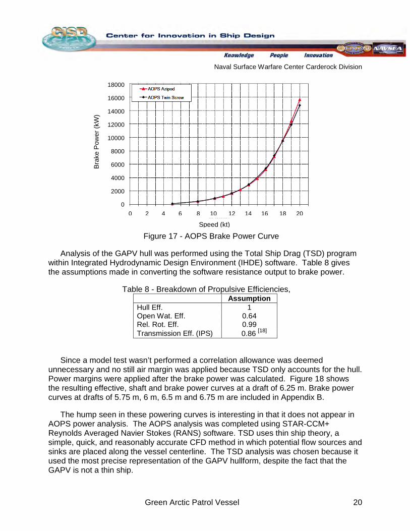
2.6 Open Water Power Requirements Analysis performed by STX Europe using Computational Fluid Dynamics (CFD)
software for the Canadian AOPS project in 2008 gave the brake power curve shown in Figure 17 for the particulars listed in Table 7 [16]
Table 7 - AOPS Principal Characteristics
.
Draft (m) 0 1 2 3 4 5 6 7 8 9 10 12
20
15
10
5
0
Met
acen
ter K
Mt (
m)
Full Ship
Lightship
Naval Surface Warfare Center Carderock Division
Green Arctic Patrol Vessel 20
Figure 17 - AOPS Brake Power Curve
Analysis of the GAPV hull was performed using the Total Ship Drag (TSD) program within Integrated Hydrodynamic Design Environment (IHDE) software. Table 8 gives the assumptions made in converting the software resistance output to brake power.
Table 8 - Breakdown of Propulsive Efficiencies,
Assumption
Hull Eff. 1 Open Wat. Eff. 0.64 Rel. Rot. Eff. 0.99 Transmission Eff. (IPS) 0.86
[18]
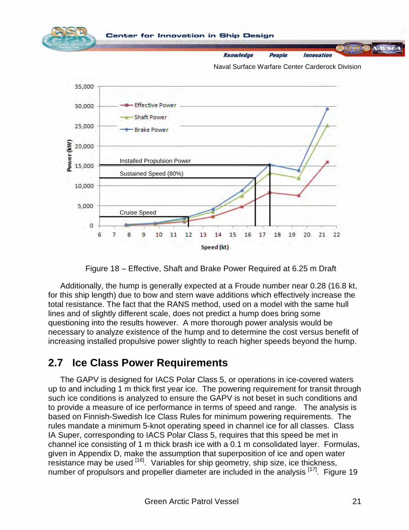
Since a model test wasn’t performed a correlation allowance was deemed unnecessary and no still air margin was applied because TSD only accounts for the hull. Power margins were applied after the brake power was calculated. Figure 18 shows the resulting effective, shaft and brake power curves at a draft of 6.25 m. Brake power curves at drafts of 5.75 m, 6 m, 6.5 m and 6.75 m are included in Appendix B.
The hump seen in these powering curves is interesting in that it does not appear in AOPS power analysis. The AOPS analysis was completed using STAR-CCM+ Reynolds Averaged Navier Stokes (RANS) software. TSD uses thin ship theory, a simple, quick, and reasonably accurate CFD method in which potential flow sources and sinks are placed along the vessel centerline. The TSD analysis was chosen because it used the most precise representation of the GAPV hullform, despite the fact that the GAPV is not a thin ship.
18000
16000
14000
12000
10000
8000
6000
4000
2000
0
Brak
e P
ower
(kW
)
0 2 4 6 8 10 12 14 16 18 20
Speed (kt)
Naval Surface Warfare Center Carderock Division
Green Arctic Patrol Vessel 21
Figure 18 – Effective, Shaft and Brake Power Required at 6.25 m Draft
Additionally, the hump is generally expected at a Froude number near 0.28 (16.8 kt, for this ship length) due to bow and stern wave additions which effectively increase the total resistance. The fact that the RANS method, used on a model with the same hull lines and of slightly different scale, does not predict a hump does bring some questioning into the results however. A more thorough power analysis would be necessary to analyze existence of the hump and to determine the cost versus benefit of increasing installed propulsive power slightly to reach higher speeds beyond the hump.
2.7 Ice Class Power Requirements The GAPV is designed for IACS Polar Class 5, or operations in ice-covered waters
up to and including 1 m thick first year ice. The powering requirement for transit through such ice conditions is analyzed to ensure the GAPV is not beset in such conditions and to provide a measure of ice performance in terms of speed and range. The analysis is based on Finnish-Swedish Ice Class Rules for minimum powering requirements. The rules mandate a minimum 5-knot operating speed in channel ice for all classes. Class IA Super, corresponding to IACS Polar Class 5, requires that this speed be met in channel ice consisting of 1 m thick brash ice with a 0.1 m consolidated layer. Formulas, given in Appendix D, make the assumption that superposition of ice and open water resistance may be used [16]. Variables for ship geometry, ship size, ice thickness, number of propulsors and propeller diameter are included in the analysis 17[ ]. Figure 19
Installed Propulsion Power
Sustained Speed (80%)
Cruise Speed
Naval Surface Warfare Center Carderock Division
Green Arctic Patrol Vessel 22
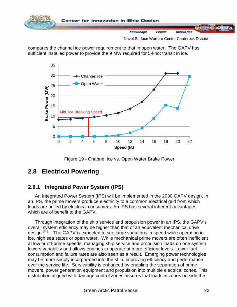
compares the channel ice power requirement to that in open water. The GAPV has sufficient installed power to provide the 9 MW required for 5-knot transit in ice.
Figure 19 - Channel Ice vs. Open Water Brake Power
2.8 Electrical Powering
2.8.1 Integrated Power System (IPS) An Integrated Power System (IPS) will be implemented in the 2030 GAPV design. In
an IPS, the prime movers produce electricity to a common electrical grid from which loads are pulled by electrical consumers. An IPS has several inherent advantages, which are of benefit to the GAPV.
Through integration of the ship service and propulsion power in an IPS, the GAPV’s overall system efficiency may be higher than that of an equivalent mechanical drive design [18]. The GAPV is expected to see large variations in speed while operating in ice, high sea states or open water. While mechanical prime movers are often inefficient at low or off-prime speeds, managing ship service and propulsion loads on one system lowers variability and allows engines to operate at more efficient levels. Lower fuel consumption and failure rates are also seen as a result. Emerging power technologies may be more simply incorporated into the ship, improving efficiency and performance over the service life. Survivability is enhanced by enabling the separation of prime movers, power generation equipment and propulsion into multiple electrical zones. This distribution aligned with damage control zones assures that loads in zones outside the
0
5
10
15
20
25
30
35
0 2 4 6 8 10 12 14 16 18 20 22
Bra
ke P
ower
(MW
)
Speed (kt)
Channel Ice
Open Water
Min. Ice Breaking Speed
Naval Surface Warfare Center Carderock Division
Green Arctic Patrol Vessel 23
damaged area do not see an interruption in power. Finally, an IPS system provides flexibility in ship arrangement and propulsion selection.
2.8.2 Propulsor GAPV operations in ice-covered waters demand a propulsion system that will
provide enhanced maneuverability as well as the structural capacity to withstand ice impacts. The use of podded propulsion on the KV Svalbard and USCGC Mackinaw has proven this system’s capability in operational conditions similar to those anticipated for the GAPV. Savings in production costs may be found by permitting late arrival in the shipyard and eliminating long shaft lines. However, unknowns to podded propulsion feasibility include reliability of bearings, shock survivability, and the added maintenance expense long term.
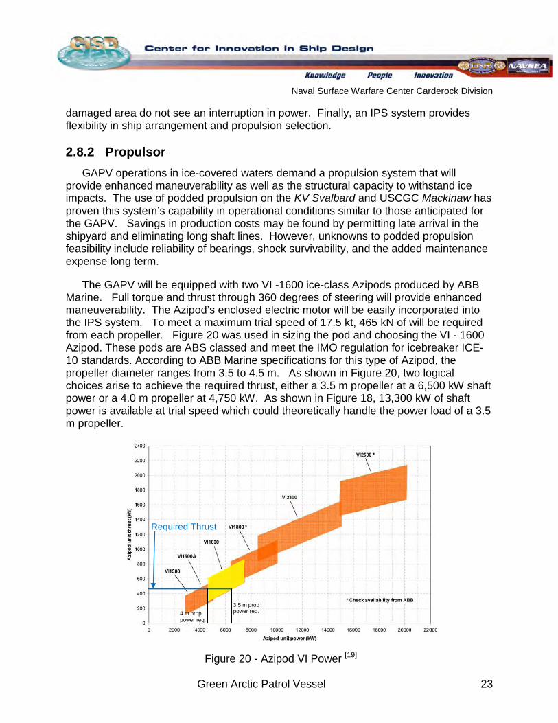
The GAPV will be equipped with two VI -1600 ice-class Azipods produced by ABB Marine. Full torque and thrust through 360 degrees of steering will provide enhanced maneuverability. The Azipod’s enclosed electric motor will be easily incorporated into the IPS system. To meet a maximum trial speed of 17.5 kt, 465 kN of will be required from each propeller. Figure 20 was used in sizing the pod and choosing the VI - 1600 Azipod. These pods are ABS classed and meet the IMO regulation for icebreaker ICE-10 standards. According to ABB Marine specifications for this type of Azipod, the propeller diameter ranges from 3.5 to 4.5 m. As shown in Figure 20, two logical choices arise to achieve the required thrust, either a 3.5 m propeller at a 6,500 kW shaft power or a 4.0 m propeller at 4,750 kW. As shown in Figure 18, 13,300 kW of shaft power is available at trial speed which could theoretically handle the power load of a 3.5 m propeller.
Figure 20 - Azipod VI Power [19]
Required Thrust
4 m prop power req.
3.5 m prop power req.
Naval Surface Warfare Center Carderock Division
Green Arctic Patrol Vessel 24
The GAPV will also be equipped with a Wärtsilä CT/FT 125 H transverse bow thruster that will enhance the ship’s maneuverability through ice. A tunnel thruster was selected over other various bow thrusters based on positioning within the hull lines for protection in ice. The CT/FT 125 H model was sized for a wind speed of 25 kt and a GAPV cross-sectional area of 627 m2 above the waterline. The 25 kt wind speed is the design condition for the AOPS [7]
2.8.3 Fuel Cells
.
Incorporation of fuel cells into a USN ship has yet to be realized, but this emerging technology has potential in its inherent efficiency and improved emissions. The GAPV design relies on the assumption that fuel cell technology will have matured to a point sufficient for onboard implementation by the 2030 timeframe. Because fuel cells require hydrogen fuel, a reformer capable of converting diesel fuel (DFM) to hydrogen and suitable for naval warship installation must also be developed in this timeline. The development of a reformer system is anticipated to be easier than solving issues associated with the acquisition and storage of hydrogen. Expectations are that this will be possible given current progress and the presumption that ultra-low sulfur fuel will be regularly available in 2030.
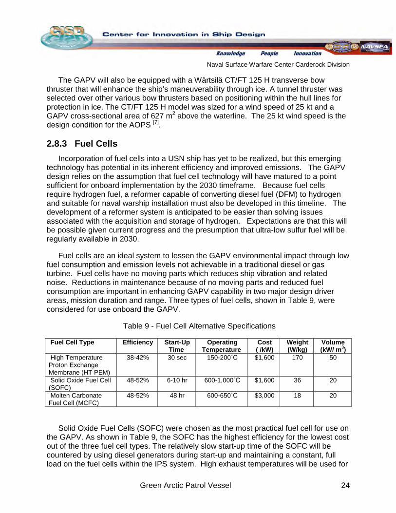
Fuel cells are an ideal system to lessen the GAPV environmental impact through low fuel consumption and emission levels not achievable in a traditional diesel or gas turbine. Fuel cells have no moving parts which reduces ship vibration and related noise. Reductions in maintenance because of no moving parts and reduced fuel consumption are important in enhancing GAPV capability in two major design driver areas, mission duration and range. Three types of fuel cells, shown in Table 9, were considered for use onboard the GAPV.
Table 9 - Fuel Cell Alternative Specifications
Fuel Cell Type Efficiency Start-Up Time
Operating Temperature
Cost ( /kW)
Weight (W/kg)
Volume (kW/ m3
High Temperature Proton Exchange Membrane (HT PEM)
) 38-42% 30 sec 150-200˚C $1,600 170 50
Solid Oxide Fuel Cell (SOFC)
48-52% 6-10 hr 600-1,000˚C $1,600 36 20
Molten Carbonate Fuel Cell (MCFC)
48-52% 48 hr 600-650˚C $3,000 18 20
Solid Oxide Fuel Cells (SOFC) were chosen as the most practical fuel cell for use on the GAPV. As shown in Table 9, the SOFC has the highest efficiency for the lowest cost out of the three fuel cell types. The relatively slow start-up time of the SOFC will be countered by using diesel generators during start-up and maintaining a constant, full load on the fuel cells within the IPS system. High exhaust temperatures will be used for
Naval Surface Warfare Center Carderock Division
Green Arctic Patrol Vessel 25
beneficial returns in the form of de-icing capability. The SOFC is the most sulfur-resistant fuel cell, making it the most likely to emerge with adequate reforming technology by 2030.
2.8.3.1 Trade Study To assess the tradeoffs in terms of cost, volume, weight and fuel consumption, a
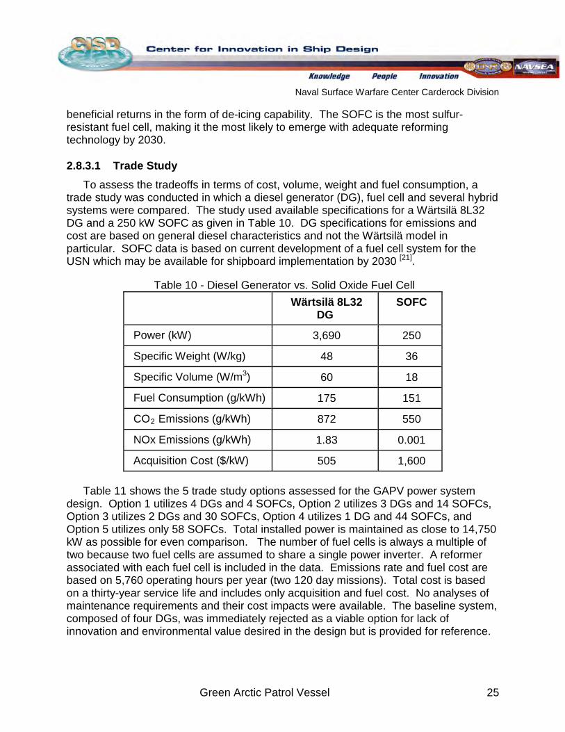
trade study was conducted in which a diesel generator (DG), fuel cell and several hybrid systems were compared. The study used available specifications for a Wärtsilä 8L32 DG and a 250 kW SOFC as given in Table 10. DG specifications for emissions and cost are based on general diesel characteristics and not the Wärtsilä model in particular. SOFC data is based on current development of a fuel cell system for the USN which may be available for shipboard implementation by 2030 [21]
Table 10 - Diesel Generator vs. Solid Oxide Fuel Cell
.
Wärtsilä 8L32 DG
SOFC
Power (kW) 3,690 250
Specific Weight (W/kg) 48 36
Specific Volume (W/m3 60 ) 18
Fuel Consumption (g/kWh) 175 151
CO2 872 Emissions (g/kWh) 550
NOx Emissions (g/kWh) 1.83 0.001
Acquisition Cost ($/kW) 505 1,600 Table 11 shows the 5 trade study options assessed for the GAPV power system
design. Option 1 utilizes 4 DGs and 4 SOFCs, Option 2 utilizes 3 DGs and 14 SOFCs, Option 3 utilizes 2 DGs and 30 SOFCs, Option 4 utilizes 1 DG and 44 SOFCs, and Option 5 utilizes only 58 SOFCs. Total installed power is maintained as close to 14,750 kW as possible for even comparison. The number of fuel cells is always a multiple of two because two fuel cells are assumed to share a single power inverter. A reformer associated with each fuel cell is included in the data. Emissions rate and fuel cost are based on 5,760 operating hours per year (two 120 day missions). Total cost is based on a thirty-year service life and includes only acquisition and fuel cost. No analyses of maintenance requirements and their cost impacts were available. The baseline system, composed of four DGs, was immediately rejected as a viable option for lack of innovation and environmental value desired in the design but is provided for reference.
Naval Surface Warfare Center Carderock Division
Green Arctic Patrol Vessel 26
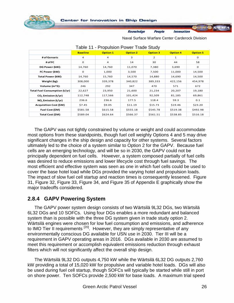
Table 11 - Propulsion Power Trade Study
Baseline Option 1 Option 2 Option 3 Option 4 Option 5
# of Gensets 4 4 3 2 1 0
# of FC 0 4 14 30 44 58
DG Power (kW): 14,760 14,760 11,070 7,380 3,690 0
FC Power (kW): 0 1,000 3,500 7,500 11,000 14,500
Total Power (kW): 14,760 15,760 14,570 14,880 14,690 14,500
Weight (kg): 308,000 339,378 340,822 389,333 422,156 454,978
Volume (m^3): 246 292 347 470 571 672
Total Fuel Consumption (t/yr) 22,627 23,950 21,600 21,234 20,207 19,180
CO2 Emission (t/yr) 112,748 117,566 101,424 92,509 81,185 69,861
NOx Emission (t/yr) 236.6 236.6 177.5 118.4 59.3 0.1
Acquisition Cost ($M) $7.45 $9.05 $11.19 $15.73 $19.46 $23.20
Fuel Cost ($M) $581.58 $615.58 $555.18 $545.78 $519.38 $492.98
Total Cost ($M) $589.04 $624.64 $566.37 $561.51 $538.85 $516.18
The GAPV was not tightly constrained by volume or weight and could accommodate most options from these standpoints, though fuel cell weighty Options 4 and 5 may drive significant changes in the ship design and capacity for other systems. Several factors ultimately led to the choice of a system similar to Option 2 for the GAPV. Because fuel cells are an emerging technology, and will be so in 2030, the GAPV could not be principally dependent on fuel cells. However, a system composed partially of fuel cells was desired to reduce emissions and lower lifecycle cost through fuel savings. The most efficient and effective system was seen as one in which fuel cells could be used to cover the base hotel load while DGs provided the varying hotel and propulsion loads. The impact of slow fuel cell startup and reaction times is consequently lessened. Figure 31, Figure 32, Figure 33, Figure 34, and Figure 35 of Appendix E graphically show the major tradeoffs considered.
2.8.4 GAPV Powering System The GAPV power system design consists of two Wärtsilä 9L32 DGs, two Wärtsilä
6L32 DGs and 10 SOFCs. Using four DGs enables a more redundant and balanced system than is possible with the three DG system given in trade study option 2. Wärtsilä engines were chosen for low fuel consumption and emissions, and adherence to IMO Tier II requirements [20]
The Wärtsilä 9L32 DG outputs 4,750 kW while the Wärtsilä 6L32 DG outputs 2,760 kW providing a total of 15,020 kW for propulsive and variable hotel loads. DGs will also be used during fuel cell startup, though SOFCs will typically be started while still in port on shore power. Ten SOFCs provide 2,500 kW for base loads. A maximum trial speed
. However, they are simply representative of any environmentally conscious DG available for USN use in 2030. Tier III will be a requirement in GAPV operating areas in 2016. DGs available in 2030 are assumed to meet this requirement or accomplish equivalent emissions reduction through exhaust filters which will not significantly affect the overall ship design.
Naval Surface Warfare Center Carderock Division
Green Arctic Patrol Vessel 27
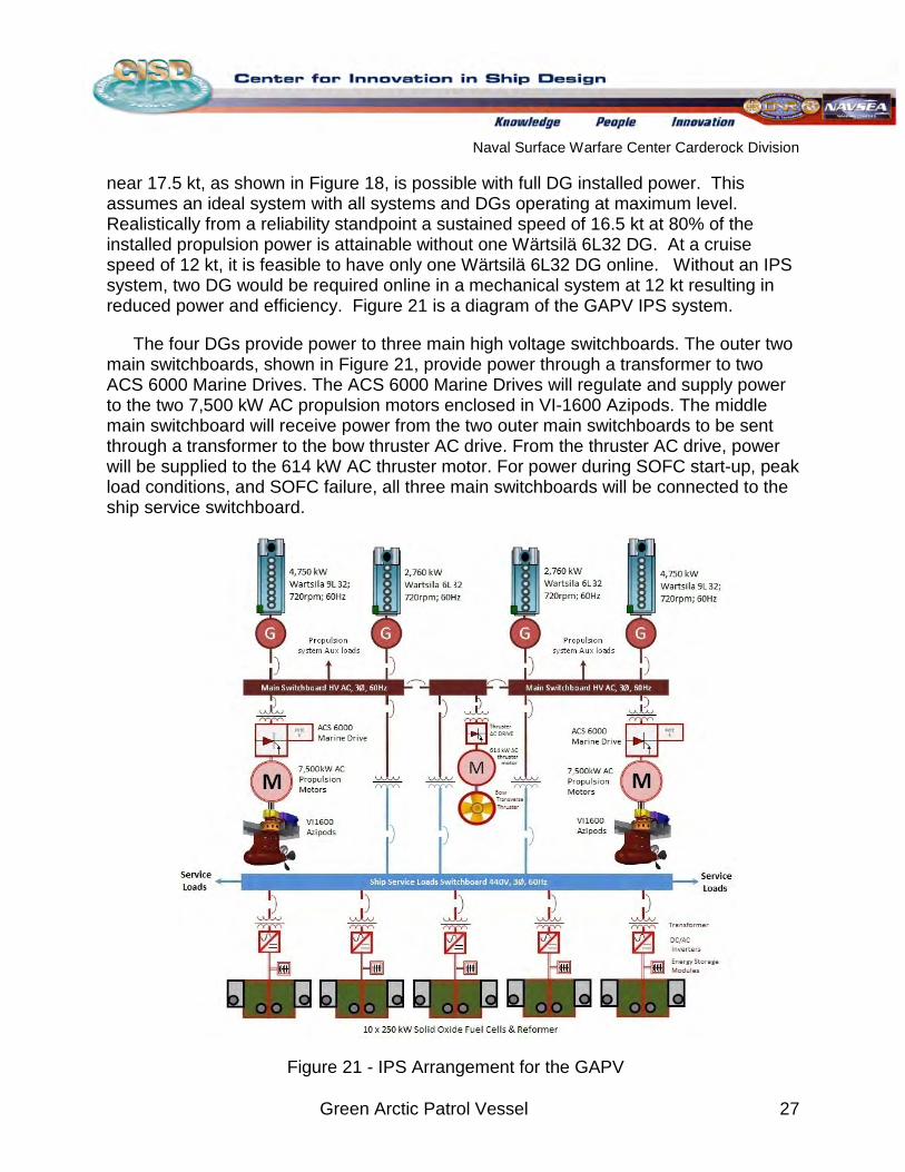
near 17.5 kt, as shown in Figure 18, is possible with full DG installed power. This assumes an ideal system with all systems and DGs operating at maximum level. Realistically from a reliability standpoint a sustained speed of 16.5 kt at 80% of the installed propulsion power is attainable without one Wärtsilä 6L32 DG. At a cruise speed of 12 kt, it is feasible to have only one Wärtsilä 6L32 DG online. Without an IPS system, two DG would be required online in a mechanical system at 12 kt resulting in reduced power and efficiency. Figure 21 is a diagram of the GAPV IPS system.
The four DGs provide power to three main high voltage switchboards. The outer two main switchboards, shown in Figure 21, provide power through a transformer to two ACS 6000 Marine Drives. The ACS 6000 Marine Drives will regulate and supply power to the two 7,500 kW AC propulsion motors enclosed in VI-1600 Azipods. The middle main switchboard will receive power from the two outer main switchboards to be sent through a transformer to the bow thruster AC drive. From the thruster AC drive, power will be supplied to the 614 kW AC thruster motor. For power during SOFC start-up, peak load conditions, and SOFC failure, all three main switchboards will be connected to the ship service switchboard.
Figure 21 - IPS Arrangement for the GAPV
Naval Surface Warfare Center Carderock Division
Green Arctic Patrol Vessel 28
The ship’s service switchboard provides power to the hotel services and electrical consumers of the GAPV. Each SOFC pair will provide power to an energy storage device and provide back-up power for the GAPV. The energy storage devices are connected to an uninterrupted power supply system that will provide instantaneous power to GAPV components and systems. The power generated from each pair of SOFCs then travels through an inverter and transformer for full integration into the GAPV IPS. The SOFCs will mainly be providing power to the hotel services of the ship and are therefore connected to the ship’s service switchboard. However, in a situation in which the four DGs fail, the ship’s service switchboard is connected to the three main switchboards to allow the SOFCs to provide emergency power to the propulsion system.
2.9 De-Icing According to DNV rules for ships navigating in ice, the heating power capacity for
de-icing shall not be less than [28]
450 W/m
:
2
200 W/m for open deck areas, helicopter decks, gangways, stairways, etc
2
50 W/m for railings for superstructures
The GAPV topside deck area is 886 m2
Given the above regulations, a total equivalent power of 400 kW is required for deck area de-icing. In addition, the GAPV has 2,280 m
.
2 of superstructure and thus requires 456 kW for its de-icing. Railings were taken into account in the additional margin placed on the de-icing load because the load is significantly lower and more difficult to estimate. Additional equipment requiring de-icing in some form, whether through heating or manual breaking, include [29]
Communication Equipment
:
Scanning Equipment Navigation Lights Window Wipers Safety Equipment Firefighting Lines and Monitors Anchors including Windlass Chain and Hawse Pipe
Air Pipe Vent Heads Air Horns Escape Exits Lifeboats with Davits Rafts Storage Facilities for Lifesaving Outfit Ventilation Inlets Scuppers and Drains
For these features, an additional 20% margin was placed on the de-icing power load. The total resulting GAPV maximum de-icing load is then taken as 1,027 kW.
[29]
Naval Surface Warfare Center Carderock Division
Green Arctic Patrol Vessel 29
2.10 Waste Heat Recovery A GAPV waste heat recovery system utilizes SOFC high temperature exhaust gas
for shipboard use. The system is designed to increase ship power efficiency by using the stored energy available in high temperature gases which otherwise would be expelled into the environment. A steam power generation system was explored, but due to maintenance, cost, efficiency and feasibility issues, a simpler heat exchanger system was chosen. Each SOFC is equipped with its own heat exchanger to capture its exiting exhaust energy. Given a 250 kW SOFC system with an exhaust temperature of 600˚C, a total of 147 kW of power may be recovered per SOFC for a total power recovery of up to 1,470 kW [24]
Heat recovery will be used to meet the 1,027 kW maximum de-icing power requirement separate from the ELA, with no direct load to ship service power. Exhaust energy will be converted into a hot water/ steam piping system using the heat exchangers. The piping system will run internally through the GAPV topside deck and superstructure, heating metal surfaces and preventing the buildup of ice. Weight associated with this system is considered in section
.
2.16, though cost and impact on ship construction was not.
2.11 Electric Load Analysis As the GAPV utilizes an IPS with podded propulsors the Electric Load Analysis
(ELA) increases in complexity when compared to traditional shafted ships. The IPS requires two major switchboards. The main switchboard carries the azimuthing pod loads and bow thruster loads and connects them to the high voltage diesel generators. The second ship service switchboard at 440V carries the loads for all the additional systems in the GAPV.
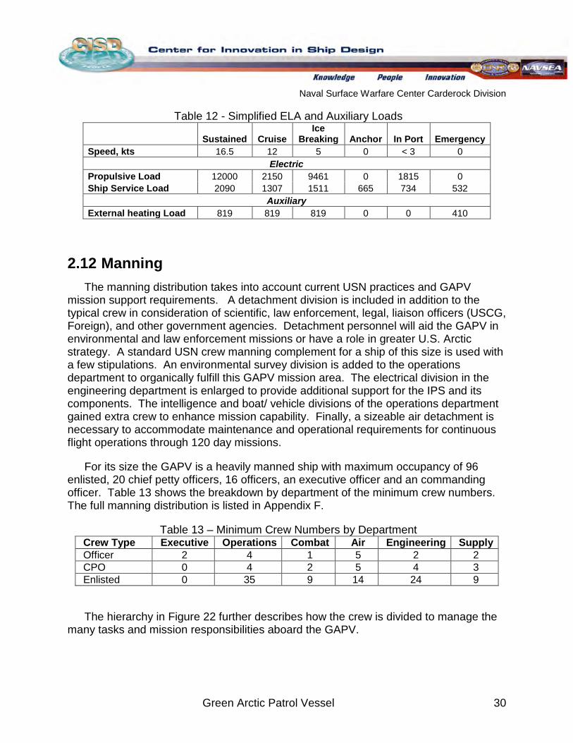
Six different electric plant loadings are evaluated to determine the expected load and power required for each. This is done by itemizing the components of each system and assigning an expected load factor to each full load to determine how much power is required and how many power sources need to be online to accommodate the load. Where certain loads were not determined for the GAPV, similar loads from the Canadian AOPS ELA are used. Sustained, Cruise, Anchor, In Port, and Emergency are monikers representing five standard electric plant loadings for USN ships. However because the GAPV is an ice-class ship, it is necessary to add an Ice Breaking electric plant loading to assess all the GAPV operational capabilities. Because the ELA is complex, a simplified version is shown in Table 12, while the full analysis is shown in Appendix G.
Naval Surface Warfare Center Carderock Division
Green Arctic Patrol Vessel 30
Table 12 - Simplified ELA and Auxiliary Loads
Sustained Cruise Ice
Breaking Anchor In Port Emergency Speed, kts 16.5 12 5 0 < 3 0
Electric Propulsive Load 12000 2150 9461 0 1815 0 Ship Service Load 2090 1307 1511 665 734 532
Auxiliary External heating Load 819 819 819 0 0 410
2.12 Manning The manning distribution takes into account current USN practices and GAPV
mission support requirements. A detachment division is included in addition to the typical crew in consideration of scientific, law enforcement, legal, liaison officers (USCG, Foreign), and other government agencies. Detachment personnel will aid the GAPV in environmental and law enforcement missions or have a role in greater U.S. Arctic strategy. A standard USN crew manning complement for a ship of this size is used with a few stipulations. An environmental survey division is added to the operations department to organically fulfill this GAPV mission area. The electrical division in the engineering department is enlarged to provide additional support for the IPS and its components. The intelligence and boat/ vehicle divisions of the operations department gained extra crew to enhance mission capability. Finally, a sizeable air detachment is necessary to accommodate maintenance and operational requirements for continuous flight operations through 120 day missions.
For its size the GAPV is a heavily manned ship with maximum occupancy of 96 enlisted, 20 chief petty officers, 16 officers, an executive officer and an commanding officer. Table 13 shows the breakdown by department of the minimum crew numbers. The full manning distribution is listed in Appendix F.
Table 13 – Minimum Crew Numbers by Department Crew Type Executive Operations Combat Air Engineering Supply Officer 2 4 1 5 2 2 CPO 0 4 2 5 4 3 Enlisted 0 35 9 14 24 9
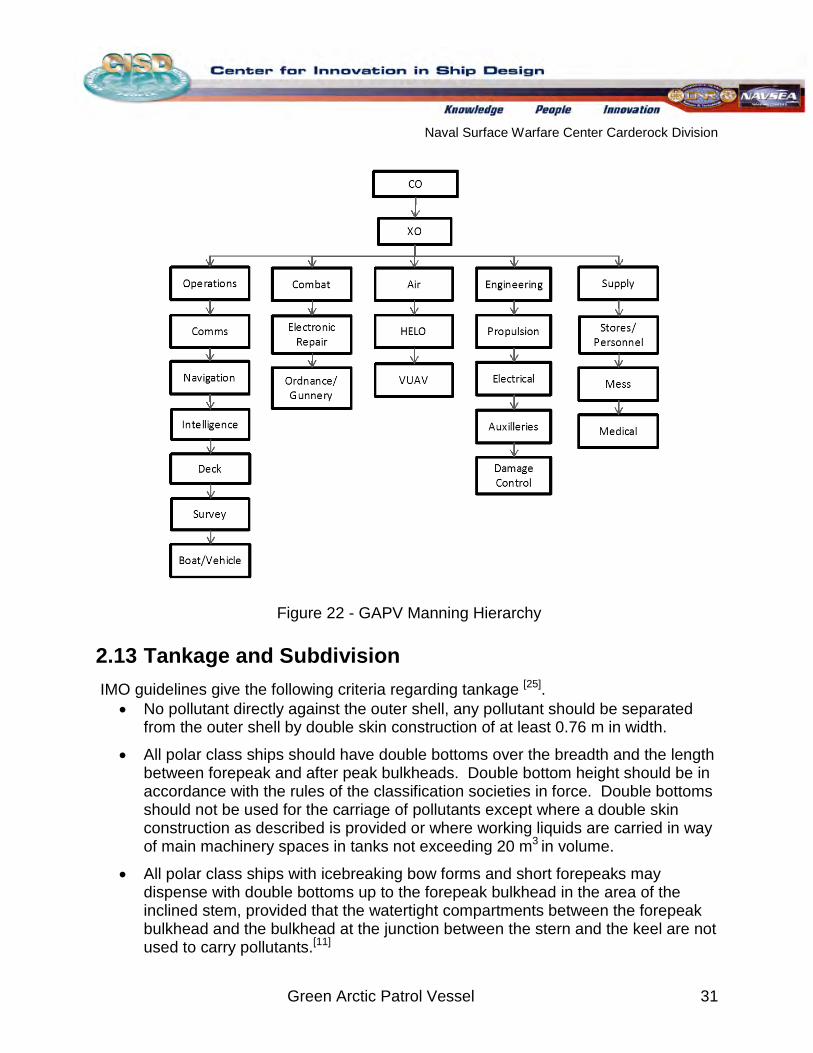
The hierarchy in Figure 22 further describes how the crew is divided to manage the many tasks and mission responsibilities aboard the GAPV.
Naval Surface Warfare Center Carderock Division
Green Arctic Patrol Vessel 31
Figure 22 - GAPV Manning Hierarchy
2.13 Tankage and Subdivision IMO guidelines give the following criteria regarding tankage [25]
• No pollutant directly against the outer shell, any pollutant should be separated from the outer shell by double skin construction of at least 0.76 m in width.
.
• All polar class ships should have double bottoms over the breadth and the length between forepeak and after peak bulkheads. Double bottom height should be in accordance with the rules of the classification societies in force. Double bottoms should not be used for the carriage of pollutants except where a double skin construction as described is provided or where working liquids are carried in way of main machinery spaces in tanks not exceeding 20 m3
• All polar class ships with icebreaking bow forms and short forepeaks may dispense with double bottoms up to the forepeak bulkhead in the area of the inclined stem, provided that the watertight compartments between the forepeak bulkhead and the bulkhead at the junction between the stern and the keel are not used to carry pollutants.
in volume.
[11]
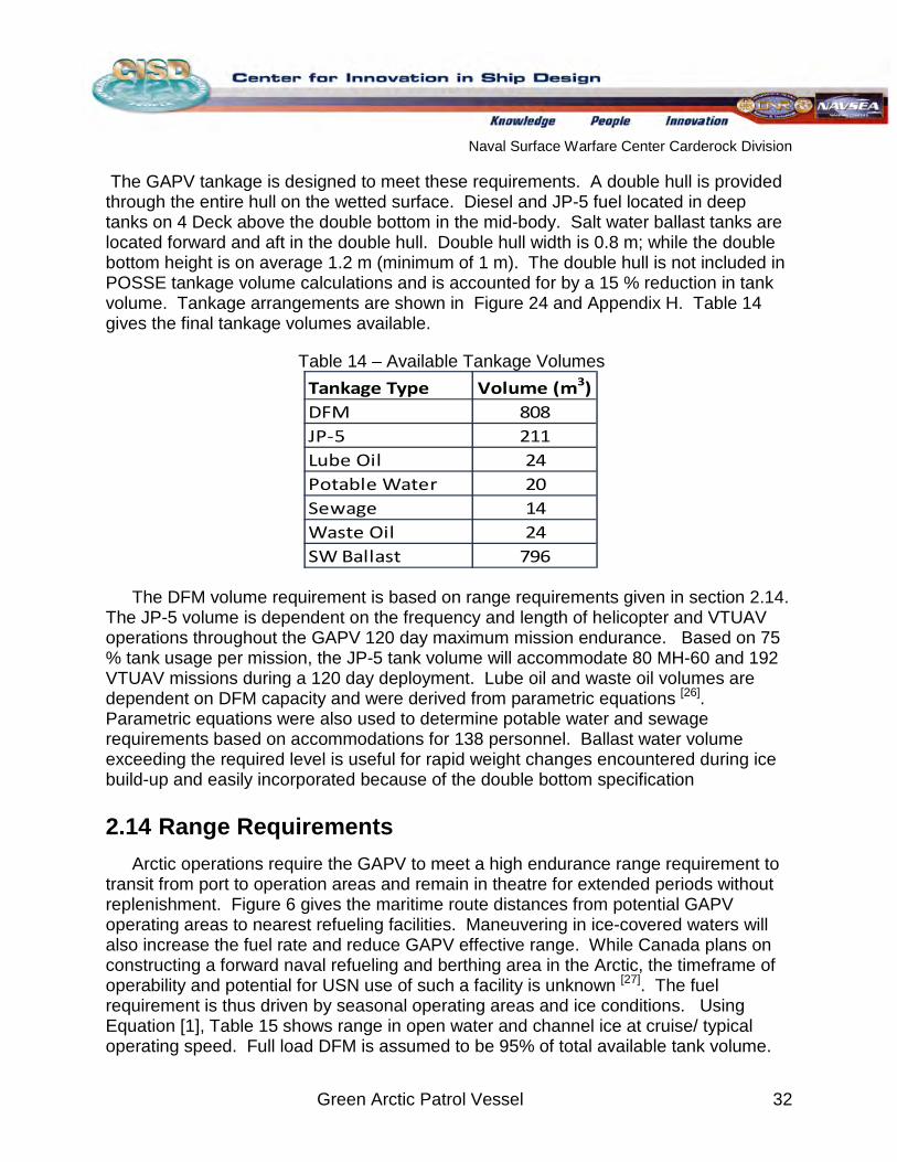
Naval Surface Warfare Center Carderock Division
Green Arctic Patrol Vessel 32
The GAPV tankage is designed to meet these requirements. A double hull is provided through the entire hull on the wetted surface. Diesel and JP-5 fuel located in deep tanks on 4 Deck above the double bottom in the mid-body. Salt water ballast tanks are located forward and aft in the double hull. Double hull width is 0.8 m; while the double bottom height is on average 1.2 m (minimum of 1 m). The double hull is not included in POSSE tankage volume calculations and is accounted for by a 15 % reduction in tank volume. Tankage arrangements are shown in Figure 24 and Appendix H. Table 14 gives the final tankage volumes available.
Table 14 – Available Tankage Volumes
Tankage Type Volume (m3)DFM 808JP-5 211Lube Oil 24Potable Water 20Sewage 14Waste Oil 24SW Ballast 796
The DFM volume requirement is based on range requirements given in section 2.14. The JP-5 volume is dependent on the frequency and length of helicopter and VTUAV operations throughout the GAPV 120 day maximum mission endurance. Based on 75 % tank usage per mission, the JP-5 tank volume will accommodate 80 MH-60 and 192 VTUAV missions during a 120 day deployment. Lube oil and waste oil volumes are dependent on DFM capacity and were derived from parametric equations [26]
2.14 Range Requirements
. Parametric equations were also used to determine potable water and sewage requirements based on accommodations for 138 personnel. Ballast water volume exceeding the required level is useful for rapid weight changes encountered during ice build-up and easily incorporated because of the double bottom specification
Arctic operations require the GAPV to meet a high endurance range requirement to transit from port to operation areas and remain in theatre for extended periods without replenishment. Figure 6 gives the maritime route distances from potential GAPV operating areas to nearest refueling facilities. Maneuvering in ice-covered waters will also increase the fuel rate and reduce GAPV effective range. While Canada plans on constructing a forward naval refueling and berthing area in the Arctic, the timeframe of operability and potential for USN use of such a facility is unknown [27]. The fuel requirement is thus driven by seasonal operating areas and ice conditions. Using Equation [1], Table 15 shows range in open water and channel ice at cruise/ typical operating speed. Full load DFM is assumed to be 95% of total available tank volume.
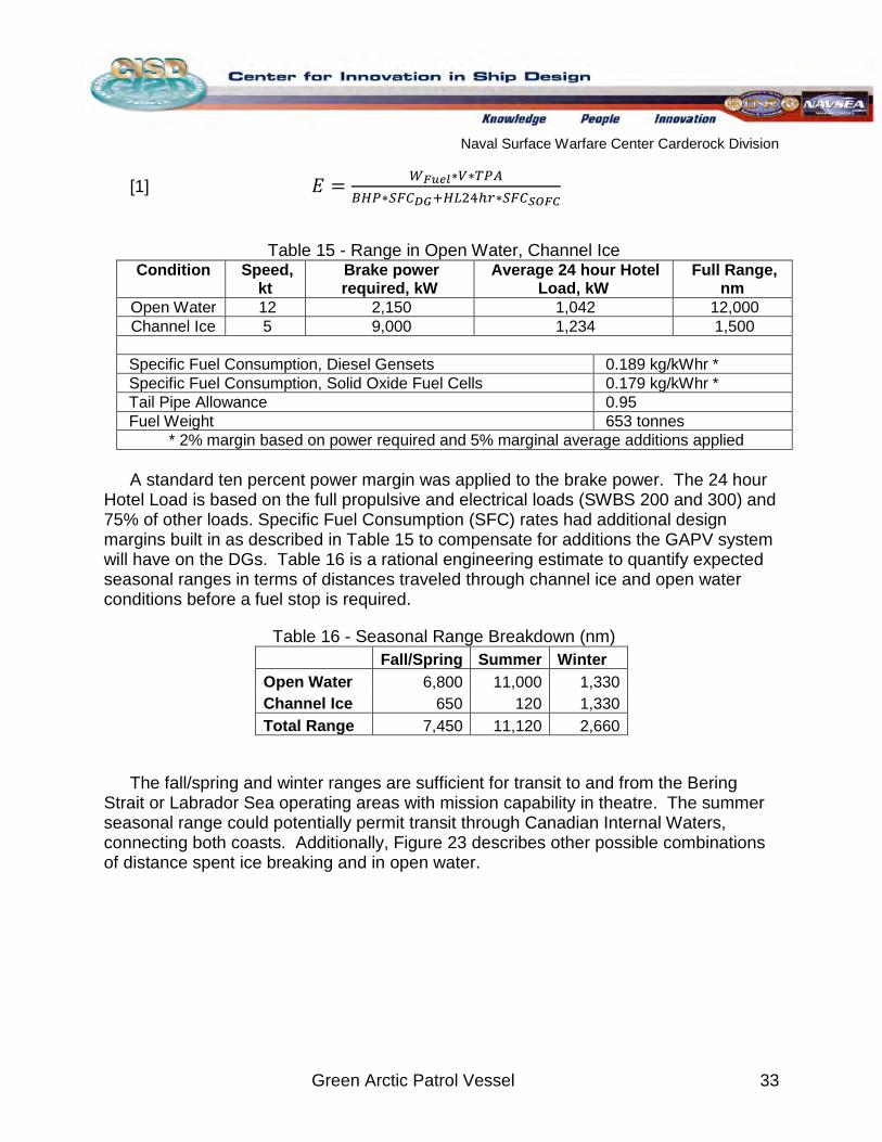
Naval Surface Warfare Center Carderock Division
Green Arctic Patrol Vessel 33
[1] 𝐸 = 𝑊𝐹𝑢𝑒𝑙∗𝑉∗𝑇𝑃𝐴𝐵𝐻𝑃∗𝑆𝐹𝐶𝐷𝐺+𝐻𝐿24ℎ𝑟∗𝑆𝐹𝐶𝑆𝑂𝐹𝐶
Table 15 - Range in Open Water, Channel Ice Condition Speed,
kt Brake power required, kW
Average 24 hour Hotel Load, kW
Full Range, nm
Open Water 12 2,150 1,042 12,000 Channel Ice 5 9,000 1,234 1,500
Specific Fuel Consumption, Diesel Gensets 0.189 kg/kWhr * Specific Fuel Consumption, Solid Oxide Fuel Cells 0.179 kg/kWhr * Tail Pipe Allowance 0.95 Fuel Weight 653 tonnes
* 2% margin based on power required and 5% marginal average additions applied A standard ten percent power margin was applied to the brake power. The 24 hour
Hotel Load is based on the full propulsive and electrical loads (SWBS 200 and 300) and 75% of other loads. Specific Fuel Consumption (SFC) rates had additional design margins built in as described in Table 15 to compensate for additions the GAPV system will have on the DGs. Table 16 is a rational engineering estimate to quantify expected seasonal ranges in terms of distances traveled through channel ice and open water conditions before a fuel stop is required.
Table 16 - Seasonal Range Breakdown (nm) Fall/Spring Summer Winter Open Water 6,800 11,000 1,330 Channel Ice 650 120 1,330 Total Range 7,450 11,120 2,660
The fall/spring and winter ranges are sufficient for transit to and from the Bering Strait or Labrador Sea operating areas with mission capability in theatre. The summer seasonal range could potentially permit transit through Canadian Internal Waters, connecting both coasts. Additionally, Figure 23 describes other possible combinations of distance spent ice breaking and in open water.
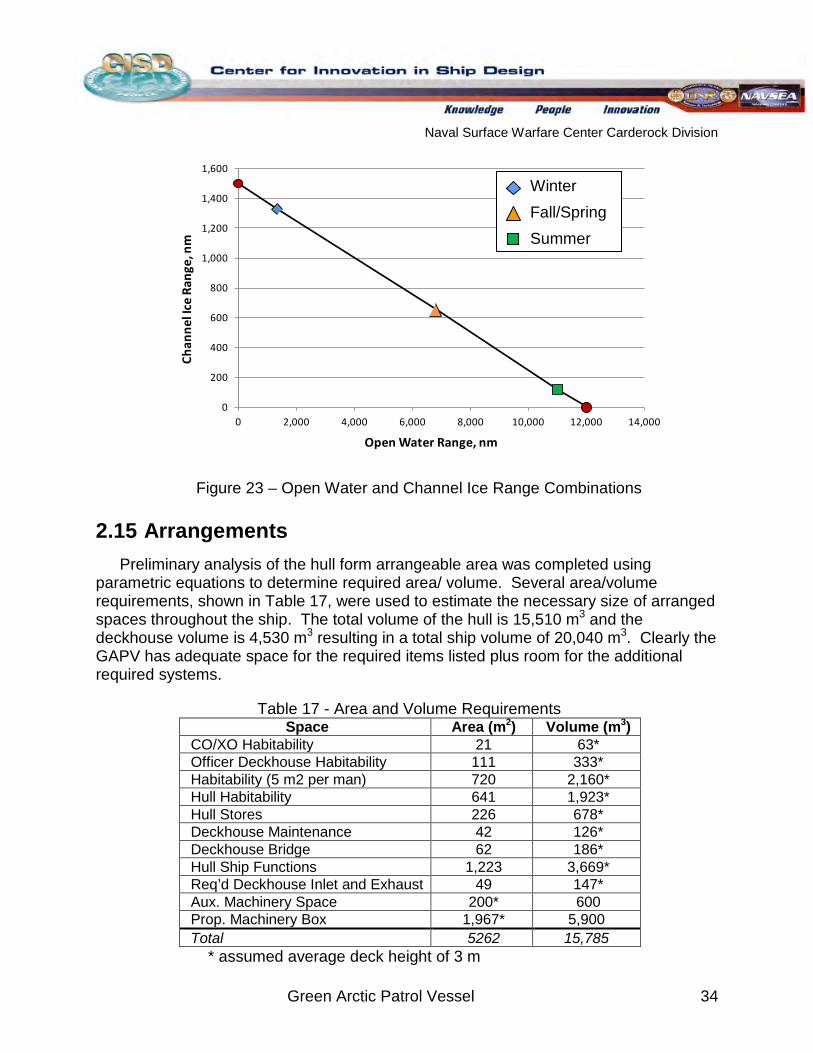
Naval Surface Warfare Center Carderock Division
Green Arctic Patrol Vessel 34
Figure 23 – Open Water and Channel Ice Range Combinations
2.15 Arrangements Preliminary analysis of the hull form arrangeable area was completed using
parametric equations to determine required area/ volume. Several area/volume requirements, shown in Table 17, were used to estimate the necessary size of arranged spaces throughout the ship. The total volume of the hull is 15,510 m3 and the deckhouse volume is 4,530 m3 resulting in a total ship volume of 20,040 m3
Table 17 - Area and Volume Requirements
. Clearly the GAPV has adequate space for the required items listed plus room for the additional required systems.
Space Area (m2 Volume (m) 3
CO/XO Habitability )
21 63* Officer Deckhouse Habitability 111 333* Habitability (5 m2 per man) 720 2,160* Hull Habitability 641 1,923* Hull Stores 226 678* Deckhouse Maintenance 42 126* Deckhouse Bridge 62 186* Hull Ship Functions 1,223 3,669* Req’d Deckhouse Inlet and Exhaust 49 147* Aux. Machinery Space 200* 600 Prop. Machinery Box 1,967* 5,900 Total 5262 15,785
* assumed average deck height of 3 m
0
200
400
600
800
1,000
1,200
1,400
1,600
0 2,000 4,000 6,000 8,000 10,000 12,000 14,000
Chan
nel I
ce R
ange
, nm
Open Water Range, nm
Winter Fall/Spring Summer
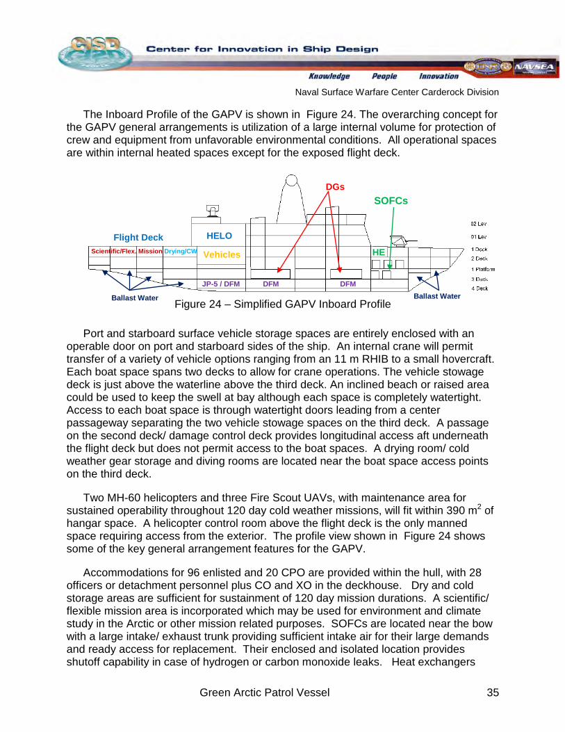
Naval Surface Warfare Center Carderock Division
Green Arctic Patrol Vessel 35
The Inboard Profile of the GAPV is shown in Figure 24. The overarching concept for the GAPV general arrangements is utilization of a large internal volume for protection of crew and equipment from unfavorable environmental conditions. All operational spaces are within internal heated spaces except for the exposed flight deck.
Figure 24 – Simplified GAPV Inboard Profile
Port and starboard surface vehicle storage spaces are entirely enclosed with an operable door on port and starboard sides of the ship. An internal crane will permit transfer of a variety of vehicle options ranging from an 11 m RHIB to a small hovercraft. Each boat space spans two decks to allow for crane operations. The vehicle stowage deck is just above the waterline above the third deck. An inclined beach or raised area could be used to keep the swell at bay although each space is completely watertight. Access to each boat space is through watertight doors leading from a center passageway separating the two vehicle stowage spaces on the third deck. A passage on the second deck/ damage control deck provides longitudinal access aft underneath the flight deck but does not permit access to the boat spaces. A drying room/ cold weather gear storage and diving rooms are located near the boat space access points on the third deck.
Two MH-60 helicopters and three Fire Scout UAVs, with maintenance area for sustained operability throughout 120 day cold weather missions, will fit within 390 m2
Figure 24
of hangar space. A helicopter control room above the flight deck is the only manned space requiring access from the exterior. The profile view shown in shows some of the key general arrangement features for the GAPV.
Accommodations for 96 enlisted and 20 CPO are provided within the hull, with 28 officers or detachment personnel plus CO and XO in the deckhouse. Dry and cold storage areas are sufficient for sustainment of 120 day mission durations. A scientific/ flexible mission area is incorporated which may be used for environment and climate study in the Arctic or other mission related purposes. SOFCs are located near the bow with a large intake/ exhaust trunk providing sufficient intake air for their large demands and ready access for replacement. Their enclosed and isolated location provides shutoff capability in case of hydrogen or carbon monoxide leaks. Heat exchangers
SOFCs DGs
Flight Deck HELO
Vehicles
DFM JP-5 / DFM DFM
Scientific/Flex. Mission Drying/CW HE
Ballast Water Ballast Water
Naval Surface Warfare Center Carderock Division
Green Arctic Patrol Vessel 36
(HE) are located above the SOFC spaces with space for associated machinery and pumps for the deck and superstructure heating system. Additional space is allocated for the deck heating system on the second deck aft of boat storage. Two pairs of DGs are separated for survivability by two bulkheads and large main machinery (MMR) and auxiliary machinery (AMR) spaces are available for placement of remaining IPS propulsion and auxiliary systems. MMR and AMR spaces include systems for heating, ballast, sea-chest, firefighting and anti-icing. Heating sources must be separated for redundancy [23]
2.16 Weights
. A satisfactory amount of arrangeable area is available for additional spaces such as recreation, garbage compaction and storage, laundry and other detailed uses not included in the concept design.
2.16.1 “Scaled” Analysis from Similar Ships A weight breakdown to three SWBS digits was estimated using linear and
polynomial regression from Polar Star, DDG 51, FFG 7 and USCG WMEC weight data. Where data was available, the three digit SWBS group was calculated from a regression of the ship’s data deemed most applicable to the GAPV for that particular weight group. Scaling particulars such as displacement, LOA or manning were used based on their relationship to the SWBS weight in question. For example, a combination of Polar Star and FFG 7 data was used in a linear regression with displacement as the scaling factor to obtain a shell plating weight estimate. This regression considers the volume of plating required and its structural requirements as a limited ice-breaking vessel to determine the GAPV’s shell plating weight. It was assumed that propulsion weight including the electric DGs would lie exclusively in SWBS 200 so that it could be scaled to other DG systems. SWBS 300 accounts for the associated cabling, control panels and other support weights scaled for the overall IPS system power.
2.16.2 “Itemized” List Analysis As design decisions were made and certain systems were defined, their associated
weight replaced the previously estimated value. The SWBS 100 group includes the hull, deckhouse, mast, foundations and associated payload weights. A margin of 17.8% was applied to the structural hull weight based on IACS Polar Class 5 requirements for hull strengthening in the ice-belt and bow areas. SWBS 200 weights include the azimuthing podded propulsion component weights, bow thruster weight and electrical propulsion powering system. Electrical power generation system components in the machinery box are given in the SWBS 300 including the SOFC component weights, heat exchangers and additional related components. Power distribution and lighting weights are also included in SWBS 300. Parametric equations were used for communications, payload, navigation, cabling and miscellaneous weights in SWBS 400.
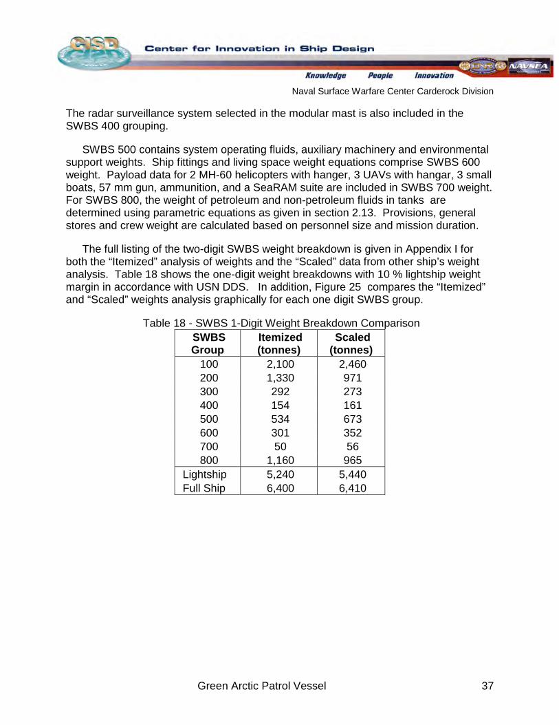
Naval Surface Warfare Center Carderock Division
Green Arctic Patrol Vessel 37
The radar surveillance system selected in the modular mast is also included in the SWBS 400 grouping.
SWBS 500 contains system operating fluids, auxiliary machinery and environmental support weights. Ship fittings and living space weight equations comprise SWBS 600 weight. Payload data for 2 MH-60 helicopters with hanger, 3 UAVs with hangar, 3 small boats, 57 mm gun, ammunition, and a SeaRAM suite are included in SWBS 700 weight. For SWBS 800, the weight of petroleum and non-petroleum fluids in tanks are determined using parametric equations as given in section 2.13. Provisions, general stores and crew weight are calculated based on personnel size and mission duration.
The full listing of the two-digit SWBS weight breakdown is given in Appendix I for both the “Itemized” analysis of weights and the “Scaled” data from other ship’s weight analysis. Table 18 shows the one-digit weight breakdowns with 10 % lightship weight margin in accordance with USN DDS. In addition, Figure 25 compares the “Itemized” and “Scaled” weights analysis graphically for each one digit SWBS group.
Table 18 - SWBS 1-Digit Weight Breakdown Comparison SWBS Group
Itemized (tonnes)
Scaled (tonnes)
100 2,100 2,460 200 1,330 971 300 292 273 400 154 161 500 534 673 600 301 352 700 50 56 800 1,160 965
Lightship 5,240 5,440 Full Ship 6,400 6,410
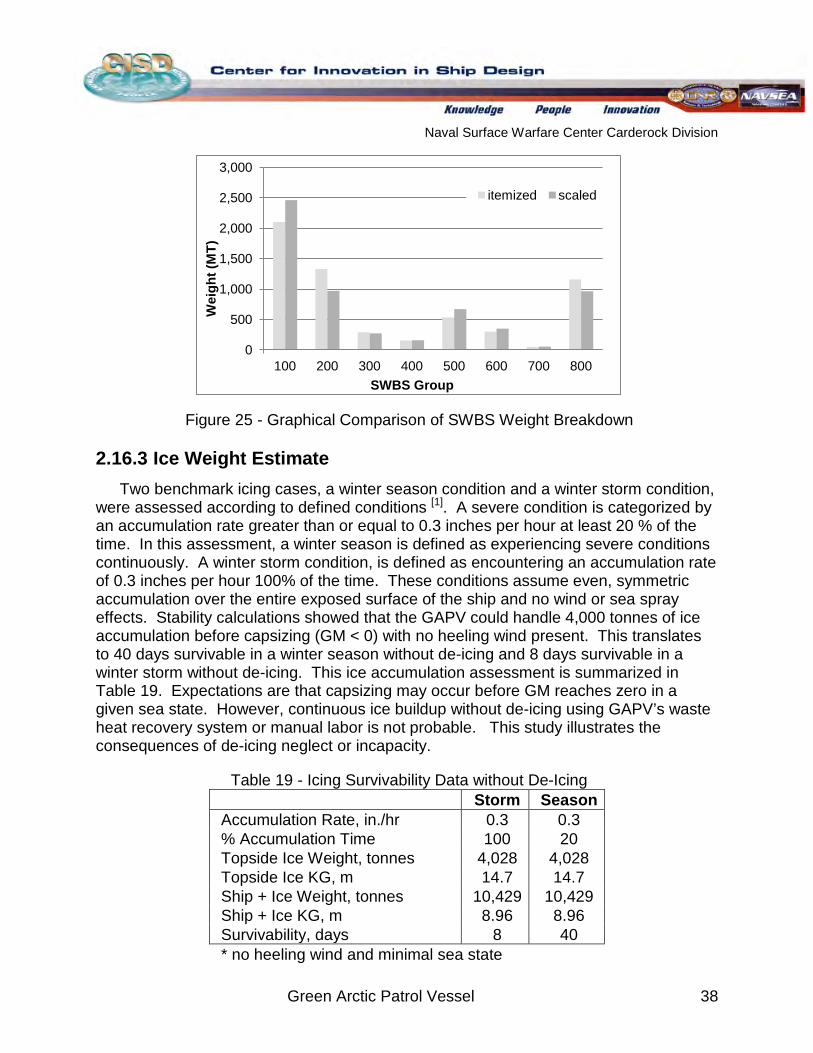
Naval Surface Warfare Center Carderock Division
Green Arctic Patrol Vessel 38
Figure 25 - Graphical Comparison of SWBS Weight Breakdown
2.16.3 Ice Weight Estimate Two benchmark icing cases, a winter season condition and a winter storm condition,
were assessed according to defined conditions [1]
Table 19 - Icing Survivability Data without De-Icing
. A severe condition is categorized by an accumulation rate greater than or equal to 0.3 inches per hour at least 20 % of the time. In this assessment, a winter season is defined as experiencing severe conditions continuously. A winter storm condition, is defined as encountering an accumulation rate of 0.3 inches per hour 100% of the time. These conditions assume even, symmetric accumulation over the entire exposed surface of the ship and no wind or sea spray effects. Stability calculations showed that the GAPV could handle 4,000 tonnes of ice accumulation before capsizing (GM < 0) with no heeling wind present. This translates to 40 days survivable in a winter season without de-icing and 8 days survivable in a winter storm without de-icing. This ice accumulation assessment is summarized in Table 19. Expectations are that capsizing may occur before GM reaches zero in a given sea state. However, continuous ice buildup without de-icing using GAPV’s waste heat recovery system or manual labor is not probable. This study illustrates the consequences of de-icing neglect or incapacity.
Storm Season Accumulation Rate, in./hr 0.3 0.3 % Accumulation Time 100 20 Topside Ice Weight, tonnes 4,028 4,028 Topside Ice KG, m 14.7 14.7 Ship + Ice Weight, tonnes 10,429 10,429 Ship + Ice KG, m 8.96 8.96 Survivability, days 8 40 * no heeling wind and minimal sea state
0
500
1,000
1,500
2,000
2,500
3,000
100 200 300 400 500 600 700 800
Wei
ght (
MT)
SWBS Group
itemized scaled
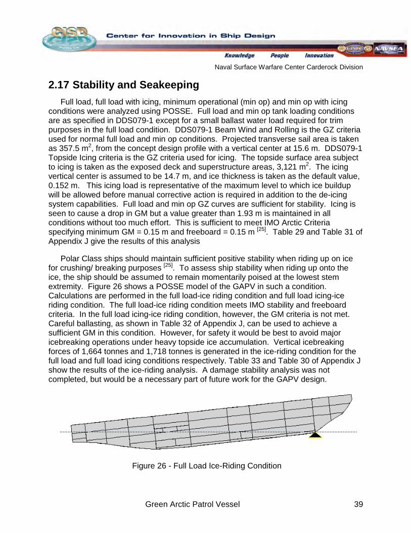
Naval Surface Warfare Center Carderock Division
Green Arctic Patrol Vessel 39
2.17 Stability and Seakeeping Full load, full load with icing, minimum operational (min op) and min op with icing
conditions were analyzed using POSSE. Full load and min op tank loading conditions are as specified in DDS079-1 except for a small ballast water load required for trim purposes in the full load condition. DDS079-1 Beam Wind and Rolling is the GZ criteria used for normal full load and min op conditions. Projected transverse sail area is taken as 357.5 m2, from the concept design profile with a vertical center at 15.6 m. DDS079-1 Topside Icing criteria is the GZ criteria used for icing. The topside surface area subject to icing is taken as the exposed deck and superstructure areas, 3,121 m2. The icing vertical center is assumed to be 14.7 m, and ice thickness is taken as the default value, 0.152 m. This icing load is representative of the maximum level to which ice buildup will be allowed before manual corrective action is required in addition to the de-icing system capabilities. Full load and min op GZ curves are sufficient for stability. Icing is seen to cause a drop in GM but a value greater than 1.93 m is maintained in all conditions without too much effort. This is sufficient to meet IMO Arctic Criteria specifying minimum GM = 0.15 m and freeboard = 0.15 m [25]
Polar Class ships should maintain sufficient positive stability when riding up on ice for crushing/ breaking purposes
. Table 29 and Table 31 of Appendix J give the results of this analysis
[25]
. To assess ship stability when riding up onto the ice, the ship should be assumed to remain momentarily poised at the lowest stem extremity. Figure 26 shows a POSSE model of the GAPV in such a condition. Calculations are performed in the full load-ice riding condition and full load icing-ice riding condition. The full load-ice riding condition meets IMO stability and freeboard criteria. In the full load icing-ice riding condition, however, the GM criteria is not met. Careful ballasting, as shown in Table 32 of Appendix J, can be used to achieve a sufficient GM in this condition. However, for safety it would be best to avoid major icebreaking operations under heavy topside ice accumulation. Vertical icebreaking forces of 1,664 tonnes and 1,718 tonnes is generated in the ice-riding condition for the full load and full load icing conditions respectively. Table 33 and Table 30 of Appendix J show the results of the ice-riding analysis. A damage stability analysis was not completed, but would be a necessary part of future work for the GAPV design.
Figure 26 - Full Load Ice-Riding Condition
Naval Surface Warfare Center Carderock Division
Green Arctic Patrol Vessel 40
A seakeeping analysis was not performed, though it is expected to be a challenging problem for the GAPV, because of combined performance requirements in open water and ice. Retractable active fin stabilizers were equipped in the AOPS design and may be a necessary feature of the GAPV for open water performance. Initial analysis of the AOPS design using ShipMo software considered transit, fueling and boat launch/ recovery in SS 6, boarding in SS 5 and helicopter operations in SS 3. The seakeeping requirements for slamming, wetness, and motion induced interruption were found to be satisfied in this analysis. No propeller emergence or operational restrictions were identified [9]. Use of the vehicle storage bay is expected only in SS2 or less because of its proximity to the waterline and was not evaluated. Further consideration of the GAPV’s ability to meet CONOPS requirements for operations in SS 6, survivability in SS 8 and helicopter operations in SS 3 are necessary.
Naval Surface Warfare Center Carderock Division
Green Arctic Patrol Vessel 41
3
3.1 Alternative Power Systems
Arctic Considerations and Green Initiatives
The GAPV can be seen as a test platform for incorporation of emerging green technology and alternative power systems leading up to 2030 and beyond. Several alternative power systems were thus considered in terms of power generation, cost, and practicality of use on the GAPV. However none of these systems were implemented in the GAPV design.
3.1.1 Wind Average wind speed in the Arctic environment ranges from 10-15 mph [28].
Incorporating wind energy devices into the GAPV is thus a plausible option to capture renewable energy. Wind turbines can generate up to 6 MW on a large scale. However, they are high in cost and large in scale 28[ ]. Many wind energy capturing devices were explored including The Fuller Wind Turbine 28[ ]
3.1.2 Solar
but not incorporated into the GAPV design based on their low power density and icing problems.
On average, the annual solar radiation during the summer in the Arctic region is 146 W/m2 [30]. Three systems were explored which could potentially utilize this solar radiation. The first systems explored were solar cells and photovoltaics. However, solar panels consume a large amount of deck area while not achieving comparable power gains. Ice build-up on solar panels will interfere with its ability to capture solar radiation making this option infeasible for the GAPV. The second system explored was solar heating which is a process that uses solar radiation to heat water. This system was not incorporated into the GAPV design because of interference from icing and a low power to weight ratio. The last system explored was a hybrid lighting system that involves a device that captures solar radiation and supplies natural lighting throughout the vessel via optical fibers. Solar Direct, LLC has developed this system in which a 48 inch diameter parabolic dish collects solar rays and focuses them into a single beam to 127 optic fibers for distribution 30 [ ]
3.1.3 Thermoelectric Generator
. Each dish can produce up to 250 W with 38% efficiency and can supply light through fibers up to 50 ft long. This system was not used on the GAPV because of icing problems interfering with the focusing of sunlight on the dish and high cost.
A thermoelectric generator (TEG) is a power system that has the ability to generate energy from a temperature difference/gradient. TEGs are currently under development but have not been extensively used or tested in a marine environment. The largest TEG
Naval Surface Warfare Center Carderock Division
Green Arctic Patrol Vessel 42
built is able to generate 1 kW of electrical power from Cummins NTC 350 Diesel engine exhaust [32]
3.1.4 Piezoelectric Transducer
. Therefore, a TEG could be implemented into the GAPV design to generate additional power for the base load through the high temperature exhaust from the SOFCs. However, further research needs to been done on implementation of TEGs in marine applications and improvement of its power to weight ratio before it can be implemented into the 2030 GAPV design.
Piezoelectric Transducers (PZT) generate electricity through applied mechanical strain. This evolving technology has been used on dance floors in London and sidewalks in New York City to generate power from the people that walk on them. According to London's Club Surya, each person on the dance floor can produce between 5 and 20 watts, depending on their activity level [33]
3.2 Coatings
. This system would work well in a marine application because the hull of a ship undergoes mechanical strain as it interacts with the water. However, PZTs will not be implemented in the GAPV design because they lack evaluation in marine applications and currently produce electricity on too small a scale.
Coatings will afford the GAPV some protection from ice interactions. Coatings will be applied throughout the entire outer surface of the ship that will be exposed to the cold weather. In addition, the ballast tanks will be coated to reduce pollution of Arctic waters. The coatings that will be applied to the ship include ice phobic, anti-fouling, and non-skid coatings. All the coatings that are being implemented are suitable for the Arctic environment. Likewise, they are all environmental friendly and comply with applicable environmental regulations. Fuel consumption savings and reduced ice buildup may also be gained through the use of coatings. Table 20 shows where each coating type is utilized on the GAPV.
Table 20 - Coating Types Type of Coating Anti-Fouling Ice Phobic Non-Skid Coatings
Location Underwater Hull Azimuthing Pods Propeller
Topside Superstructure
Flight Deck Hanger Walkways Brow
Boat Deck Forecastle Bridge Wings
3.3 Waste Management Buildup of solid and liquid wastes during 120 day missions must be treated
according to IMO regulations. The GAPV is equipped with systems that are able to treat both solid and liquid waste onboard the vessel to create safe discharge that will not harm the Arctic marine life. Solid waste which requires treatment includes plastics,
Naval Surface Warfare Center Carderock Division
Green Arctic Patrol Vessel 43
glass, metal, food waste, paper, and cardboard products. Expected solid waste rates for the GAPV are given in Table 21 [30]. Treated liquid wastes include blackwater (sewage), greywater (showers, sinks, galley water), and bilgewater (oily water). The GAPV liquid waste generation rates are given in Table 22 and Table 23 [30]
Table 21 - Solid Waste Generation
.
Generation Rate (lb/person/day)
Weight for Crew of 134 (lb/day)
Weight for 120 Day Mission (lb)
Plastics 0.2 26.8 3,216 Paper & Cardboard 1.11 148.74 17,849 Glass & Metal 0.54 72.36 8,683 Food 1.21 162.14 19,457 Total 3.06 410.04 49,205
Table 22 - Non-Oily Waste Generation Rate
(gal/person/day) Weight Crew of 134
(gal/day) Weight for 120 Day
Mission (gal) Non-Oily 48 6,432 771,840
Table 23 - Oily Waste
Generation Rate (ton/yr)
Discharge Rate at Port ($/ton)
Oily 1,620 162
A System for Total Environmental Protection (STEP) created by Terragon Environmental Technologies Inc. is incorporated into the GAPV for disposal of waste [36]. The system is currently under development and has not been tested for marine use, but is assumed to be implementable by 2030. This system has the capability to simultaneously treat both solid and liquid wastes in a single compact system. STEP combines the solid waste treatment system, Micro Auto Gasification System, and the liquid waste treatment system, Wastewater Electrochemical Treatment Technology, previously studied for use on the GAPV 30[ ]. “STEP will convert all incoming solid and liquid waste into inert ash, gaseous fuel, sanitized inorganic material and pathogen-free clean water that can be safely discharged into most environments or recycled” 36[ ]
3.4 Ballast Water treatment:
. In addition, STEP can be operated by non-technical personnel and may be left largely unattended.
The introduction of alien marine species to new environments such as the Arctic via ships’ ballast water has become one of the four greatest threats to the world’s oceans
[37]. Once the new species enter the environment, they may quickly reproduce and
Naval Surface Warfare Center Carderock Division
Green Arctic Patrol Vessel 44
destroy the local ecosystems. As a result, the IMO has placed strict regulations on ballast water discharge, requiring ships to carry an approved ballast water treatment system. The GAPV is equipped with an IMO-compliant PureBallast 2.0 treatment system [38]
3.5 Materials
. The system operates chemical-free by running water through a physical filtration process and then through a UV radiation process to eradicate organisms.
Material possibilities for the GAPV were examined based on their ability to withstand the harsh Arctic environment, weight, cost and the practicality of incorporation by the year 2030. An ideal material for the GAPV is one which can withstand the fatigue caused by ice and sea state, is lightweight and has low acquisition and maintenance costs. Steel is the primary material used by ice class ships already in existence. It is a proven material that has the capability to withstand ice interactions, is generally low in cost and can resist temperatures as low as -40˚C. The GAPV will thus use steel construction. However, advancements in composites and other materials mentioned in Appendix K may be viable alternatives by 2030.
Naval Surface Warfare Center Carderock Division
Green Arctic Patrol Vessel 45
Conclusion Environmental changes associated with global warming, and developing political and
economic initiatives in the Arctic region have brought a renewed interest in maritime operations in the far north. The 2011 GAPV project developed a USN concept vessel capable of providing a dedicated independent capability to undertake patrol, support diplomatic initiatives and project a U.S. military presence in this region. The design must integrate environmentally conscious technologies and concepts.
Expected 2030 environmental conditions and USN Arctic strategy were used to define the necessary GAPV operational capabilities. These include ability to maneuver safely in ice-covered waters, persistently monitor the global maritime domain, respond to disasters or personnel in distress, deter and defend against threats and survey the Arctic environment during self-sustained extended deployments.
The GAPV hullform is designed for combined seakeeping and ice-breaking aptitude. The hull lines are derived from the KV-Svalbard and Canadian Navy AOPS concept through which the hull’s dual capability has been proven in high sea states and ice-covered waters. A large volume superstructure shelters crew and equipment from the elements. A robust air complement enhances mission capability and expands area coverage. The GAPV armament is sufficient for defensive readiness with only limited offensive power. Two flexible vehicle storage bays can accommodate a range of potential Arctic surface craft as determined by specific mission needs.
The GAPV uses an IPS consisting of four DGs and ten SOFCs. The installed propulsion power of 15 MW is sufficient to reach a maximum speed of 17.5 kt. Twin ice class Azipods power the GAPV to provide enhanced maneuverability in ice operations and flexibility in ship design. SOFCs are incorporated into the IPS to power the base hotel load while reducing fuel consumption and emissions. Heat exchangers recoup energy lost in the high temperature exhaust from SOFCs and use it to meet power demands for topside de-icing. Additional green technologies include the use of IMO Tier II diesel engines, a waste management system, recycled steel, a ballast water treatment system, and non-toxic coatings.
The GAPV represents a balanced, feasible concept design that takes into account and accommodates for harsh Arctic environmental conditions as well as the multi-mission requirements anticipated for a USN Arctic patrol vessel.
Naval Surface Warfare Center Carderock Division
Green Arctic Patrol Vessel 46
Recommendations for Future Work After the completion of the GAPV design several considerations were identified
which call for further investigation. These include:
• Vehicle storage bay feasibility and positioning
• Environmental affect on C4ISR equipment and combat systems
• Alternative superstructure materials
• De-icing/ waste heat recovery system feasibility
• Shipboard integration of fuel cells
• Seakeeping and damage stability
Naval Surface Warfare Center Carderock Division
Green Arctic Patrol Vessel 47
References 1. Systems Planning and Analysis, Inc. "Navy Arctic Capabilities Based Assessment." 15 Nov.
2010. Assessment. Task Force Climate Change, United States Navy.
2. Testimony by Mead Treadwell, Chair US Arctic Research Commission “Is America Prepared For An Accessible Arctic?” Subcommittee on Coast Guard and Maritime Transportation Rayburn House Office Building Room 2167, Washington, DC 2:00 pm, July 16, 2008
3. United States. Cong. Committees on Appropriations. Report to Congress: U.S. Coast Guard Polar Operations. 110th Cong.
4. United States Coast Guard. USCG D17 Arctic Brief. By Christopher C. Colvin.
5. United States. Department of the Navy. Navy Arctic Roadmap. N.p.: n.p., 2009. Print.
6. "KV Svalbard." Marine Traffic.com. N.p., n.d. Web. 28 July 2011. <http://marinetraffic.com/ais/shipdetails.aspx?mmsi=259040000>.
7. "Arctic/Offshore Patrol Ship." National Defense and the Canadian Forces. Assistant Deputy Minister (Materiel), n.d. Web. 28 July 2011. <http://www.forces.gc.ca/aete/arcticoffshorepatrolshippmoaopsprojetnavirevaisseaudepatrouilleenmerenarctiquebgpnpea-eng.asp>.
8. United States. Cong. Committees on Appropriations. Report to Congress: U.S. Coast Guard Polar Operations. 110th Cong. N.p., n.d. Web. 18 July 2011.
9. AOPS Industry Day, November 13, 2008 Dan McGreer Principal Engineer, STX Canada Marine Inc.
10. Czimmek, Dieter W. Icebreaker bow and hull form. Newport News Shipbuilding and Dry Dock Company, assignee. Patent 5176092. 5 Jan. 1993. PatentGenius. N.p., n.d. Web. 18 July 2011. <http://www.patentgenius.com/patent/ 5176092.html>.
11. Deltamarin. "Ice Class Ships." Deltamarin.com. N.p., n.d. Web. 18 July 2011. <www.deltamarin.com/references/ice-class-ships/ice_class.pdf>.
12. MT Jan. 2011, Vessel Report: Barents Sea Icebreakers
13. Paris Fire Scout X Briefing. N.p.: n.p., n.d. Northrop Grumman. Web. 28 July 2011. <www.northropgrumman.com/Paris/.../2011-paris-fire-scout-x-briefing.pdf>.
14. Department of the Navy. "Air Capable Ship Aviation Facilities Bulletin No. 1J." Robert Heffley Engineering. Robert K. Heffley, n.d. Web. 28 July 2011. <http://www.robertheffley.com/docs/CV_environ/NAVAIR%20Air%20Capable%20Ship%20Aviation%20Facilities%20Bulletin%201J.pdf>.
15. Vyselaar, Dan. CFD Developments and R&D Projects at STX Marine. N.p.: n.p., n.d. CD-adapco. Web. 28 July 2011. <http://www.cd-adapco.com/pdfs/ presentations/adm09/stx-vyselaar.pdf>.
Naval Surface Warfare Center Carderock Division
Green Arctic Patrol Vessel 48
16. Riska, Kaj, et al. Performance of Merchant Vessels in Ice in the Baltic. N.p.: n.p., n.d. Liikennevirasto. Web. 28 July 2011. <http://portal.liikennevirasto.fi/portal/page/portal/fma_fi/merenkulun_palvelut/talvimerenkulku/tutkimus/Winter%20Navigation%20Research%20Board/No%2052%20Performance%20of%20merchant%20vessels%20in%20ice%20in%20the%20Balt.pdf>.
17. Juva, Mikko, and Kaj Riska. On the Power Requirement in the Finnish-Swedish Ice Class Rules. Espoo: Helsinki University of Technology, 2002. Print.
18. Doerry, Norbert H. Next Generation Integrated Power Systems of the Future Fleet.
19. ABB Oy, Marine. Azipod VI Series Product Information. N.p.: n.p., n.d. ABB. Web.
20. Wärtsilä Generating Sets. Wärtsilä, 2011. Web. 28 July 2011. <http://www.wartsila.com/en/gensets/wartsila-gensets/generating-sets>.
20 July 2011. <http://www05.abb.com/global/scot/scot293.nsf/veritydisplay/f524ca488f88beb2c12576e3004a96d8/$file/Azipod_VI_project_guide_v5.pdf>.
21. CISD Fuel Cell Ship Integration Study
22. Det Norske Veritas. Ships for Navigation in Ice. N.p.: n.p., n.d. dnv.com. Web.
23. Det Norske Veritas. "Part 6 Chapter 1: Miscellaneous Notations." Rules for Classification of Ships. July 2005. DNV Exchange. Web. 22 July 2011. <http://exchange.dnv.com/publishing/RulesShip/2005-07/ts601.pdf>.
20 July 2011. <http://exchange.dnv.com/publishing/RulesShip/2010-07/ts501.pdf>.
24. "Exhaust Gas Heat Exchangers." Bowman. N.p., n.d. Web. 28 July 2011. <http://www.ejbowman.co.uk/products/ExhaustHeatExchangers.htm>.
25. International Marine Organization. "Guidelines for Ships Operating in Arctic Ice-Covered Waters." NOAA Office of the General Counsel. National Oceanic and Atmospheric Administration, n.d. Web. 26 July 2011. <http://www.gc.noaa.gov/documents/gcil_1056-MEPC-Circ399.pdf>.
26. Brown, Dr. Alan. Virginia Tech AOE 4066 Ship Design Notes
27. Canwest News Service. "Deep-water naval port in Arctic in doubt." Canada.com. N.p., n.d. Web. 28 July 2011. <http://www.canada.com/nationalpost/story.html?id=a138a76d-880c-4ad2-b190-96a579b8ce82&k=60611>.
28. United States. U.S. Navy. Naval Arctic Manual. N.p.: n.p., 2007. Print.
29. Thomas, Justin. "New Record: World’s Largest Wind Turbine." MetaEfficient. N.p., 3 Feb. 2008. Web. 21 July 2011. <http://www.metaefficient.com/news/ new-record-worlds-largest-wind-turbine-7-megawatts.html>.
30. George, Charlotte, et al. “Green Arctic Patrol Vessel.” 30 Oct. 2010. File last modified on 30 July 2010. Technical Report. Naval Surface Warfare Center, Center for Innovation in Ship Design.
Naval Surface Warfare Center Carderock Division
Green Arctic Patrol Vessel 49
31. “Distributed Power Generation.” Sunlight Direct. Sunlight Direct LLC, 2011. Web. 18 July 2011. <http://www.sunlight-direct.com/power-generation.php>.
32. John C. Bass, Aleksandr S. Kusch, Norbert B. Elsnew, Thermoelectric Generator (TEG) for Heavy Diesel Trucks, Hi-Z Technology, Inc., 2001.
33. Diamond, Kim. “Breakthroughs in Piezoelectric Power: Raising Public Awareness is a Step in the Right Direction for U.S. Sustainable Development.” renewablesbiz. N.p., 17 Mar. 2009. Web. 18 July 2011. <http://www.renewablesbiz.com/article/09/04/breakthroughs-piezoelectric-power-raising-public-awareness-step-right-direction-us-sustainable-development?quicktabs_4=2>.
34. Wang, Ye-Ling. The U. S. Navy’s Shipboard Solid Waste Program: Managing a Highly Accelerated Fleet-wide Ship System Integration Program. N.p.: n.p., n.d. Print.
35. Thorsson, Martin, and Tommy Nielsen. Setting New Standards for Oily Water Treatment. N.p.: n.p., n.d. Print.
36. "technologies.STEP." Terragon Environmental Technologies Inc. N.p., n.d. Web. 20
37. “The Problem.” Globallast. IMO, n.d. Web. 18 July 2011. <http://globallast.imo.org/problem.htm>.
July 2011. <http://www.terragon.net/STEP.html>.
38. "PureBallast 2.0 – ballast water treatment system." Alfa Laval. N.p., n.d. Web.
20 July 2011. <http://www.alfalaval.com/solution-finder/products/pureballast/Pages/Pureballast.aspx?NoOfResults=1&ResultPosition1&source=http%3A//www.alfalaval.com/solution-finder/products/Pages/default.aspx%3Ftype%3DProductCategory%26firstItemID%3D7c60328d-45ac-4150-873e-9b8ced637cb1>.
Naval Surface Warfare Center Carderock Division
Green Arctic Patrol Vessel 50
Appendix A - GAPV Study Guide
The combined impact of shrinking sea ice in the Arctic Ocean and the growing desire by Northern Hemisphere nations to exploit the natural resources available within has resulted in renewed interest in maritime operations in the far north.
Introduction
In this environment, both the USN and USCG have recently published strategies relating to Arctic Ocean operations and their expected future infrastructure and equipment needs to support them. It is likely, therefore, that a significant amount of effort will be required in the future to patrol the region and to protect U.S. interests.
It is expected that an Arctic Patrol Vessel may be required to provide a dedicated independent capability to undertake patrol and support diplomatic initiatives with military capability. As a result of this need an initial concept Arctic Patrol Vessel was developed during a CISD summer project in 2009, and was further developed during a CISD summer project in 2010.
The previous projects focused on evolving the design developed in 2009 to incorporate a range of ‘green’ technologies and design features with the aim of reducing the impact of the design on the environment. A secondary aim was reducing the vessels overall total ownership costs.
The emphasis on ‘greening’ the design is based on several factors, which include:
In an effort to reduce environmental impact and the U.S. dependency on foreign oil the U.S. Secretary of the Navy has called for having half the fleets energy demand met through the use of alternative fuels and technologies by the year 2020;
Reducing demand for fuel is likely to have significant benefits in terms of endurance, required supportability, and hence infrastructure cost reduction in operations far from major bases (e.g. reducing transport cost for fuel delivered to Arctic bases);
The Arctic is likely to be subject to a greater level of environmental restrictions than other marine operating areas in the future – hence an arctic patrol vessel should be at the forefront of environmentally friendly technological development.
This year’s group is to take the information from the previous groups and design a Green Arctic Patrol Vehicle from the beginning incorporating green technologies outlined by last year’s group.
Naval Surface Warfare Center Carderock Division
Green Arctic Patrol Vessel 51
1. To design an Arctic Offshore Patrol Vessel capable of undertaking both long patrol deployments in extreme conditions and to undertake limited military missions to protect vital U.S. interests in the Arctic.
Objectives
2. The project should aim to integrate green technologies and design features aboard an Arctic Patrol Vessel concept to minimize the vessel’s impact on the environment through its life – this should be achieved at a systems level.
3. The project should aim to identify technical issues and requirements associated with that design that require further investigation and development.
4. The technologies used should be shown to be feasible with Navy or commercial standards and availability within the coming decades.
Ship Design 1. The vessel shall be capable of undertaking all of the missions outlined for the Arctic
Patrol Vessel in the APV report from 2009 and 2010.
Requirements
2. The following concepts are likely to be investigated (this list should not be considered exhaustive):
3. Power systems - Future electrical power systems, motors, generation options, and alternative fuels;
4. Novel propulsor and hull design features to maximize efficiency; 5. Advanced materials & coatings for reduced build cost, lighter structure, reduced
maintenance, and/or reduced environmental impact through life (sustainability); 6. A range of auxiliary systems – improved ballast water management; noise reduction
systems; use of sustainable lubricants; improved thermal management; improved anti-icing systems; reduced electrical consumption; reduced water use; improved emission reduction or capture systems etc.
7. Restrictions on operations, systems, and equipment due to the extreme environmental conditions.
8. Constraints 9. The report and design shall be unclassified. 10. The vessel shall be designed to meet the implied design requirements of the
original Arctic Patrol Vessel design and also to meet the classification and safety regulations relating to a vessel with an appropriate Arctic operating regime.
1. The team should review previous Arctic Patrol Vessel concepts Approach
2. The team will review requirements and then brainstorm potential ideas. 3. Suitable ideas shall be assessed for architectural, environmental, ship interface,
and performance impacts as well as technical feasibility. 4. The competing ideas shall be reduced to a preferred concept using a decision
making process.
Naval Surface Warfare Center Carderock Division
Green Arctic Patrol Vessel 52
5. A complete ship synthesis shall be undertaken. A balanced ship design shall result with performance analyses and a general arrangement developed. A stability assessment shall be made which includes the effects of topside icing.
6. The implications of any new technology or operational issues shall be noted. Recommendations for follow on work shall be developed.
1. During the first 2 weeks the team will produce a team project plan of actions, assignments and milestones to be presented to CISD leadership for approval. During the project this plan shall be maintained.
Deliverables
2. The team will develop and give informal intermediate presentations and a final project presentation.
3. The resulting ship design shall be detailed including a single sheet summary of characteristics, estimated performance, a comprehensive SWBS weight breakdown, a hullform body plan and a full general arrangement drawing.
4. The project will be documented in a CISD Technical Report. The final report and presentation shall be suitable for unclassified public release.
5. The team will be encouraged to produce a technical paper from the final report that is suitable for publishing at professional society conference
1. Research and Clarify Tasks
2. Arctic operations to categorize missions for an arctic patrol vessel. 3. Restrictions to missions, operations, systems, and equipment due to arctic
environment. 4. Hull Design 5. Hydrostatics 6. Weights and Centers (SWBS) 7. Perform stability calculations 8. Propulsion selection 9. Ship arrangements 10. Report
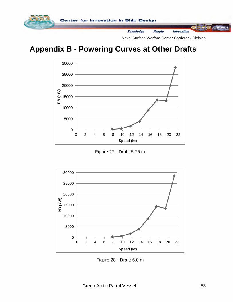
Naval Surface Warfare Center Carderock Division
Green Arctic Patrol Vessel 53
Appendix B - Powering Curves at Other Drafts
Figure 27 - Draft: 5.75 m
Figure 28 - Draft: 6.0 m
0
5000
10000
15000
20000
25000
30000
0 2 4 6 8 10 12 14 16 18 20 22
PB (k
W)
Speed (kt)
0
5000
10000
15000
20000
25000
30000
0 2 4 6 8 10 12 14 16 18 20 22
PB (k
W)
Speed (kt)
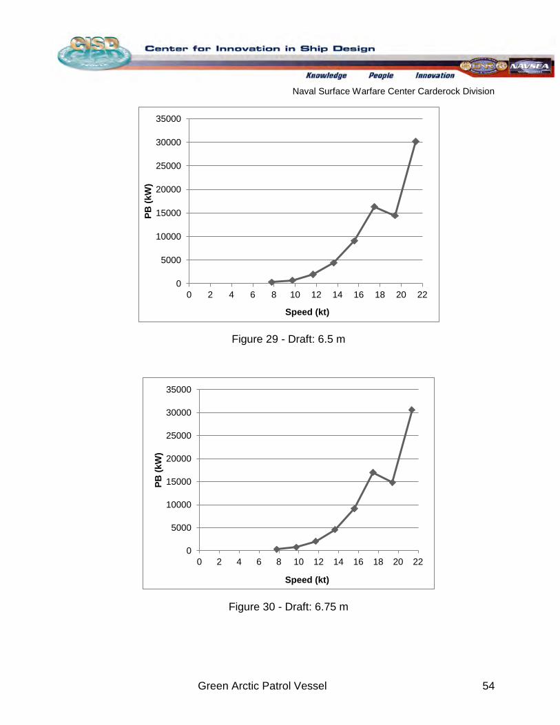
Naval Surface Warfare Center Carderock Division
Green Arctic Patrol Vessel 54
Figure 29 - Draft: 6.5 m
Figure 30 - Draft: 6.75 m
0
5000
10000
15000
20000
25000
30000
35000
0 2 4 6 8 10 12 14 16 18 20 22
PB (k
W)
Speed (kt)
0
5000
10000
15000
20000
25000
30000
35000
0 2 4 6 8 10 12 14 16 18 20 22
PB (k
W)
Speed (kt)
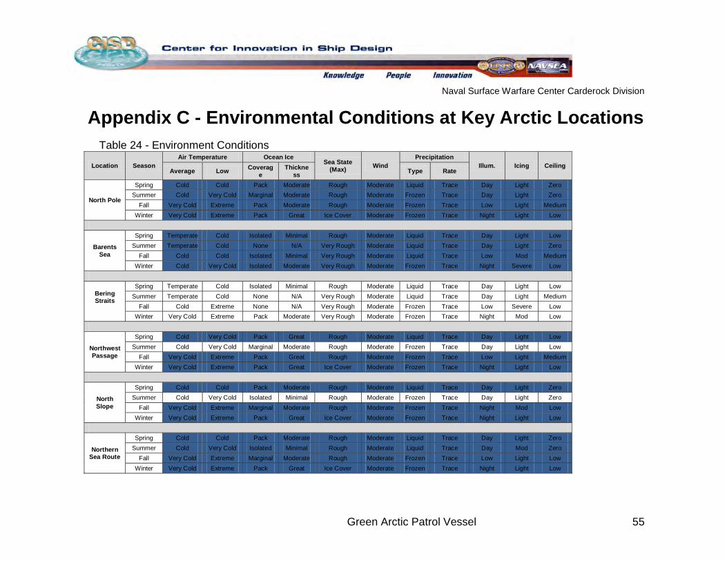
Naval Surface Warfare Center Carderock Division
Green Arctic Patrol Vessel 55
Appendix C - Environmental Conditions at Key Arctic Locations Table 24 - Environment Conditions
Location Season Air Temperature Ocean Ice
Sea State (Max) Wind
Precipitation Illum. Icing Ceiling
Average Low Coverage
Thickness Type Rate
North Pole
Spring Cold Cold Pack Moderate Rough Moderate Liquid Trace Day Light Zero Summer Cold Very Cold Marginal Moderate Rough Moderate Frozen Trace Day Light Zero
Fall Very Cold Extreme Pack Moderate Rough Moderate Frozen Trace Low Light Medium Winter Very Cold Extreme Pack Great Ice Cover Moderate Frozen Trace Night Light Low
Barents Sea
Spring Temperate Cold Isolated Minimal Rough Moderate Liquid Trace Day Light Low Summer Temperate Cold None N/A Very Rough Moderate Liquid Trace Day Light Zero
Fall Cold Cold Isolated Minimal Very Rough Moderate Liquid Trace Low Mod Medium Winter Cold Very Cold Isolated Moderate Very Rough Moderate Frozen Trace Night Severe Low
Bering Straits
Spring Temperate Cold Isolated Minimal Rough Moderate Liquid Trace Day Light Low Summer Temperate Cold None N/A Very Rough Moderate Liquid Trace Day Light Medium
Fall Cold Extreme None N/A Very Rough Moderate Frozen Trace Low Severe Low Winter Very Cold Extreme Pack Moderate Very Rough Moderate Frozen Trace Night Mod Low
Northwest Passage
Spring Cold Very Cold Pack Great Rough Moderate Liquid Trace Day Light Low Summer Cold Very Cold Marginal Moderate Rough Moderate Frozen Trace Day Light Low
Fall Very Cold Extreme Pack Great Rough Moderate Frozen Trace Low Light Medium Winter Very Cold Extreme Pack Great Ice Cover Moderate Frozen Trace Night Light Low
North Slope
Spring Cold Cold Pack Moderate Rough Moderate Liquid Trace Day Light Zero Summer Cold Very Cold Isolated Minimal Rough Moderate Frozen Trace Day Light Zero
Fall Very Cold Extreme Marginal Moderate Rough Moderate Frozen Trace Night Mod Low Winter Very Cold Extreme Pack Great Ice Cover Moderate Frozen Trace Night Light Low
Northern Sea Route
Spring Cold Cold Pack Moderate Rough Moderate Liquid Trace Day Light Zero Summer Cold Very Cold Isolated Minimal Rough Moderate Liquid Trace Day Mod Zero
Fall Very Cold Extreme Marginal Moderate Rough Moderate Frozen Trace Low Light Low Winter Very Cold Extreme Pack Great Ice Cover Moderate Frozen Trace Night Light Low
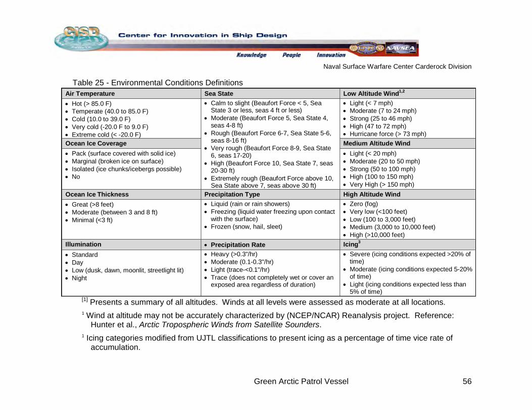
Naval Surface Warfare Center Carderock Division
Green Arctic Patrol Vessel 56
Table 25 - Environmental Conditions Definitions
[1] Presents a summary of all altitudes. Winds at all levels were assessed as moderate at all locations. 1 Wind at altitude may not be accurately characterized by (NCEP/NCAR) Reanalysis project. Reference:
Hunter et al., Arctic Tropospheric Winds from Satellite Sounders. 1
Air Temperature Sea State Low Altitude Wind1,2 • Hot (> 85.0 F) • Temperate (40.0 to 85.0 F) • Cold (10.0 to 39.0 F) • Very cold (-20.0 F to 9.0 F) • Extreme cold (< -20.0 F)
• Calm to slight (Beaufort Force < 5, Sea State 3 or less, seas 4 ft or less)
• Moderate (Beaufort Force 5, Sea State 4, seas 4-8 ft)
• Rough (Beaufort Force 6-7, Sea State 5-6, seas 8-16 ft)
• Very rough (Beaufort Force 8-9, Sea State 6, seas 17-20)
• High (Beaufort Force 10, Sea State 7, seas 20-30 ft)
• Extremely rough (Beaufort Force above 10, Sea State above 7, seas above 30 ft)
• Light (< 7 mph) • Moderate (7 to 24 mph) • Strong (25 to 46 mph) • High (47 to 72 mph) • Hurricane force (> 73 mph)
Ocean Ice Coverage Medium Altitude Wind • Pack (surface covered with solid ice) • Marginal (broken ice on surface) • Isolated (ice chunks/icebergs possible) • No
• Light (< 20 mph) • Moderate (20 to 50 mph) • Strong (50 to 100 mph) • High (100 to 150 mph) • Very High (> 150 mph)
Ocean Ice Thickness Precipitation Type High Altitude Wind • Great (>8 feet) • Moderate (between 3 and 8 ft) • Minimal (<3 ft)
• Liquid (rain or rain showers) • Freezing (liquid water freezing upon contact
with the surface) • Frozen (snow, hail, sleet)
• Zero (fog) • Very low (<100 feet) • Low (100 to 3,000 feet) • Medium (3,000 to 10,000 feet) • High (>10,000 feet)
Illumination • Precipitation Rate Icing3 • Standard • Day • Low (dusk, dawn, moonlit, streetlight lit) • Night
• Heavy (>0.3"/hr) • Moderate (0.1-0.3"/hr) • Light (trace-<0.1"/hr) • Trace (does not completely wet or cover an
exposed area regardless of duration)
• Severe (icing conditions expected >20% of time)
• Moderate (icing conditions expected 5-20% of time)
• Light (icing conditions expected less than 5% of time)
Icing categories modified from UJTL classifications to present icing as a percentage of time vice rate of accumulation.
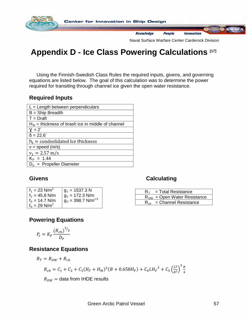
Naval Surface Warfare Center Carderock Division
Green Arctic Patrol Vessel 57
Appendix D - Ice Class Powering Calculations
[17]
Using the Finnish-Swedish Class Rules the required inputs, givens, and governing equations are listed below. The goal of this calculation was to determine the power required for transiting through channel ice given the open water resistance.
Required Inputs L = Length between perpendiculars B = Ship Breadth T = Draft HM
Ɣ = 2˚ = thickness of brash ice in middle of channel
δ = 22.6˚ hI = condsolidated Ice thickness v = speed (m/s) v1 = 2.57 m/s KP
D = 1.44
p
= Propeller Diameter
Givens Calculating
Powering Equations
𝑃𝑠 = 𝐾𝑃(𝑅𝑐ℎ)3 2�
𝐷𝑃
Resistance Equations 𝑅𝑇 = 𝑅𝑂𝑊 + 𝑅𝑐ℎ
𝑅𝑐ℎ = 𝐶1 + 𝐶2 + 𝐶3(𝐻𝐹 + 𝐻𝑀)2(𝐵 + 0.658𝐻𝐹) + 𝐶4𝐿𝐻𝐹2 + 𝐶5 �𝐿𝑇𝐵2�3 𝐵4
𝑅𝑂𝑊 = data from IHDE results
RT
R = Total Resistance
OW
R = Open Water Resistance
ch
f
= Channel Resistance
1 = 23 N/m g2 1f
= 1537.3 N 2 g = 45.8 N/m 2
f = 172.3 N/m
3 g = 14.7 N/m 3 = 398.7 N/mf
1.5 4 = 29 N/m 2
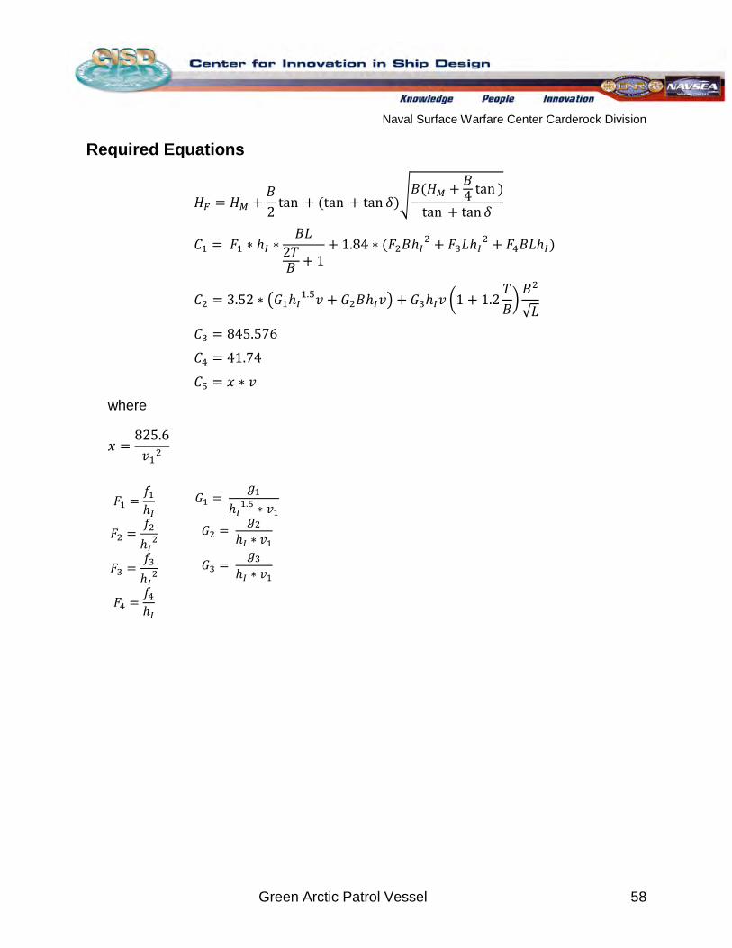
Naval Surface Warfare Center Carderock Division
Green Arctic Patrol Vessel 58
Required Equations
𝐻𝐹 = 𝐻𝑀 +𝐵2
tan + (tan + tan 𝛿)�𝐵(𝐻𝑀 + 𝐵
4 tan )tan + tan 𝛿
𝐶1 = 𝐹1 ∗ ℎ𝐼 ∗𝐵𝐿
2𝑇𝐵 + 1
+ 1.84 ∗ (𝐹2𝐵ℎ𝐼2 + 𝐹3𝐿ℎ𝐼
2 + 𝐹4𝐵𝐿ℎ𝐼)
𝐶2 = 3.52 ∗ �𝐺1ℎ𝐼1.5𝑣 + 𝐺2𝐵ℎ𝐼𝑣� + 𝐺3ℎ𝐼𝑣 �1 + 1.2
𝑇𝐵�𝐵2
√𝐿
𝐶3 = 845.576
𝐶4 = 41.74
𝐶5 = 𝑥 ∗ 𝑣 where
𝑥 =825.6𝑣12
𝐹1 =𝑓1ℎ𝐼
𝐺1 = 𝑔1
ℎ𝐼1.5 ∗ 𝑣1
𝐹2 =𝑓2ℎ𝐼2 𝐺2 =
𝑔2ℎ𝐼 ∗ 𝑣1
𝐹3 =𝑓3ℎ𝐼2 𝐺3 =
𝑔3ℎ𝐼 ∗ 𝑣1
𝐹4 =𝑓4ℎ𝐼
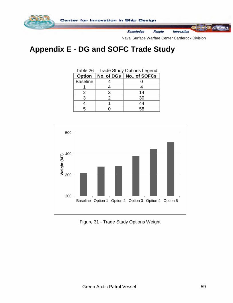
Naval Surface Warfare Center Carderock Division
Green Arctic Patrol Vessel 59
Appendix E - DG and SOFC Trade Study
Table 26 – Trade Study Options Legend Option No. of DGs No., of SOFCs
Baseline 4 0 1 4 4 2 3 14 3 2 30 4 1 44 5 0 58
Figure 31 - Trade Study Options Weight
200
300
400
500
Baseline Option 1 Option 2 Option 3 Option 4 Option 5
Wei
ght (
MT)
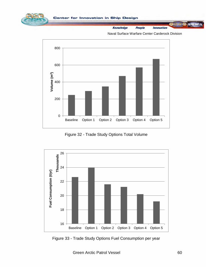
Naval Surface Warfare Center Carderock Division
Green Arctic Patrol Vessel 60
Figure 32 - Trade Study Options Total Volume
Figure 33 - Trade Study Options Fuel Consumption per year
0
200
400
600
800
Baseline Option 1 Option 2 Option 3 Option 4 Option 5
Volu
me
(m3 )
16
18
20
22
24
26
Baseline Option 1 Option 2 Option 3 Option 4 Option 5
Fuel
Con
sum
ptio
n (t/
yr) Th
ousa
nds
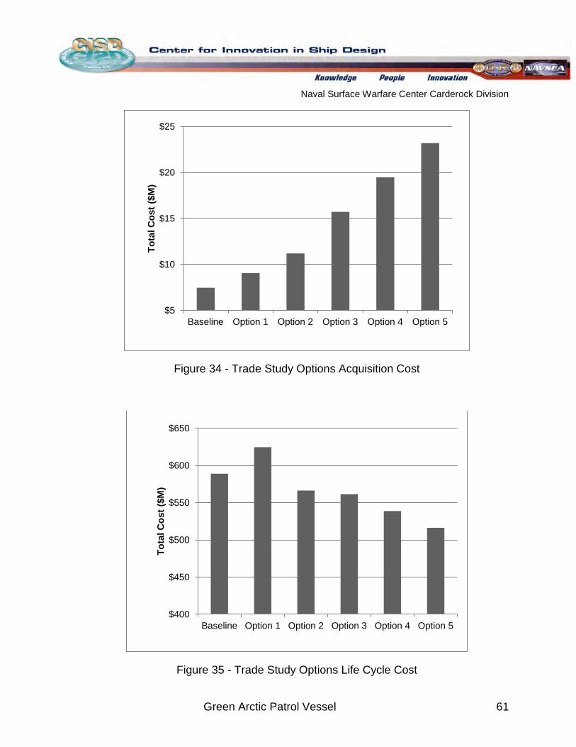
Naval Surface Warfare Center Carderock Division
Green Arctic Patrol Vessel 61
Figure 34 - Trade Study Options Acquisition Cost
Figure 35 - Trade Study Options Life Cycle Cost
$5
$10
$15
$20
$25
Baseline Option 1 Option 2 Option 3 Option 4 Option 5
Tota
l Cos
t ($M
)
$400
$450
$500
$550
$600
$650
Baseline Option 1 Option 2 Option 3 Option 4 Option 5
Tota
l Cos
t ($M
)
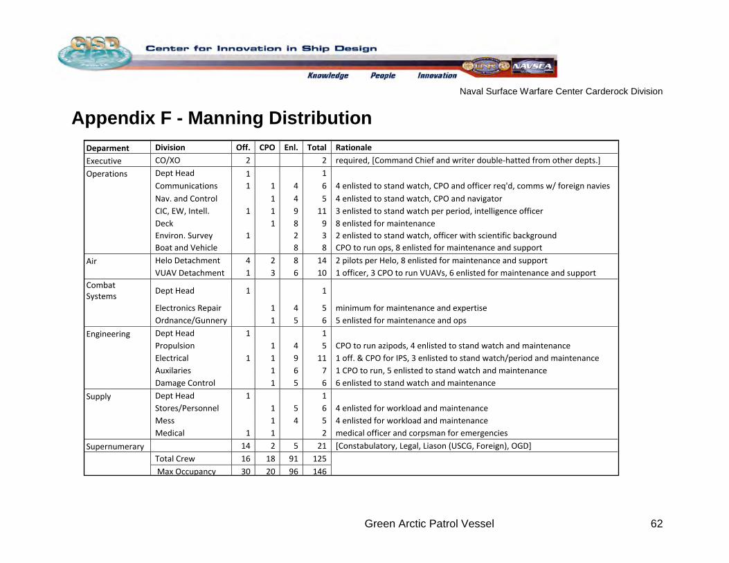
Naval Surface Warfare Center Carderock Division
Green Arctic Patrol Vessel 62
Appendix F - Manning Distribution
Deparment Division Off. CPO Enl. Total Rationale
Executive CO/XO 2 2 required, [Command Chief and writer double-hatted from other depts.]
Operations Dept Head 1 1
Communications 1 1 4 6 4 enlisted to stand watch, CPO and officer req'd, comms w/ foreign navies
Nav. and Control 1 4 5 4 enlisted to stand watch, CPO and navigator
CIC, EW, Intell. 1 1 9 11 3 enlisted to stand watch per period, intelligence officer
Deck 1 8 9 8 enlisted for maintenance Environ. Survey 1 2 3 2 enlisted to stand watch, officer with scientific background Boat and Vehicle 8 8 CPO to run ops, 8 enlisted for maintenance and support
Air Helo Detachment 4 2 8 14 2 pilots per Helo, 8 enlisted for maintenance and support
VUAV Detachment 1 3 6 10 1 officer, 3 CPO to run VUAVs, 6 enlisted for maintenance and support Combat Systems
Dept Head 1 1
Electronics Repair 1 4 5 minimum for maintenance and expertise
Ordnance/Gunnery 1 5 6 5 enlisted for maintenance and ops
Engineering Dept Head 1
1
Propulsion 1 4 5 CPO to run azipods, 4 enlisted to stand watch and maintenance
Electrical 1 1 9 11 1 off. & CPO for IPS, 3 enlisted to stand watch/period and maintenance
Auxilaries 1 6 7 1 CPO to run, 5 enlisted to stand watch and maintenance
Damage Control 1 5 6 6 enlisted to stand watch and maintenance
Supply Dept Head 1
1
Stores/Personnel 1 5 6 4 enlisted for workload and maintenance
Mess 1 4 5 4 enlisted for workload and maintenance
Medical 1 1 2 medical officer and corpsman for emergencies
Supernumerary 14 2 5 21 [Constabulatory, Legal, Liason (USCG, Foreign), OGD]
Total Crew 16 18 91 125
Max Occupancy 30 20 96 146
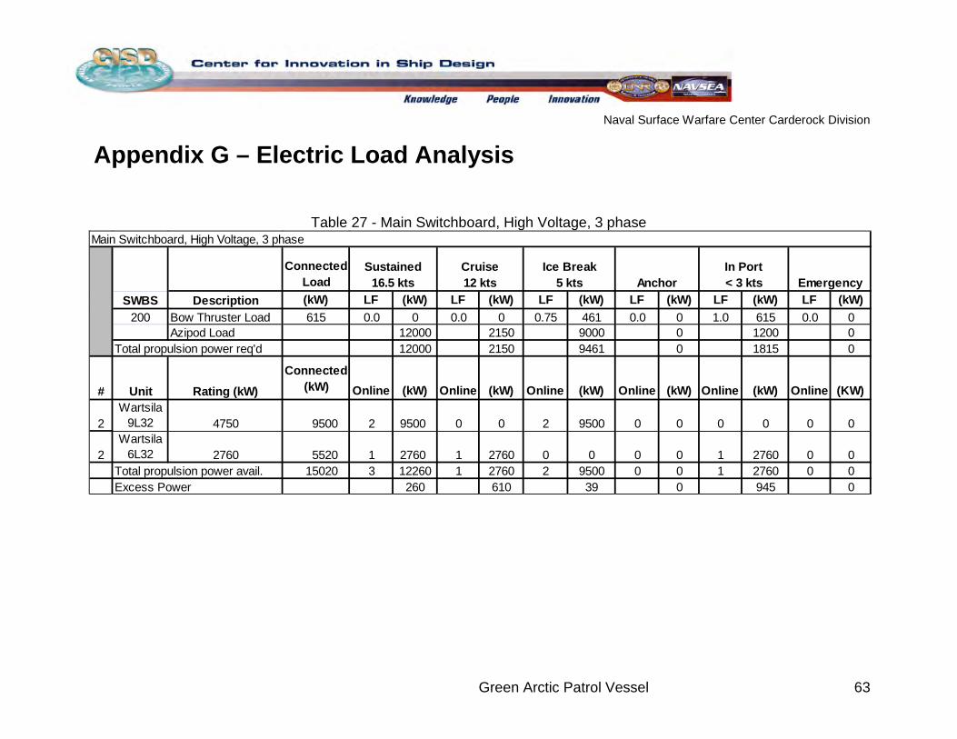
Naval Surface Warfare Center Carderock Division
Green Arctic Patrol Vessel 63
Appendix G – Electric Load Analysis
Table 27 - Main Switchboard, High Voltage, 3 phase
Main Switchboard, High Voltage, 3 phase
Connected Load
SWBS Description (kW) LF (kW) LF (kW) LF (kW) LF (kW) LF (kW) LF (kW)200 Bow Thruster Load 615 0.0 0 0.0 0 0.75 461 0.0 0 1.0 615 0.0 0
Azipod Load 12000 2150 9000 0 1200 0Total propulsion power req'd 12000 2150 9461 0 1815 0
# Unit Rating (kW)
Connected (kW) Online (kW) Online (kW) Online (kW) Online (kW) Online (kW) Online (KW)
2Wartsila
9L32 4750 9500 2 9500 0 0 2 9500 0 0 0 0 0 0
2Wartsila
6L32 2760 5520 1 2760 1 2760 0 0 0 0 1 2760 0 0Total propulsion power avail. 15020 3 12260 1 2760 2 9500 0 0 1 2760 0 0Excess Power 260 610 39 0 945 0
EmergencySustained
16.5 ktsCruise 12 kts
Ice Break 5 kts Anchor
In Port < 3 kts
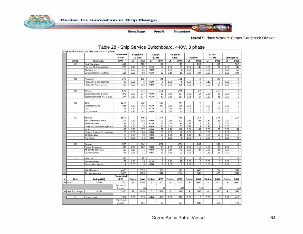
Naval Surface Warfare Center Carderock Division
Green Arctic Patrol Vessel 64
Table 28 - Ship Service Switchboard, 440V, 3 phase
Ship Service Loads Switchboard, 440V, 3 phaseConnected
Load SWBS Description (kW) LF (kW) LF (kW) LF (kW) LF (kW) LF (kW) LF (kW)
100 Deck Machinery 456 120 39 93 239 81 302Fwd and Aft Anchor/Winch 270 0.10 27 0.10 27 0.30 81 0.50 135 0.30 81 0.50 135Stabilizer Unit 70 0.50 35 0.00 0 0.00 0 0.00 0 0.00 0 0.90 63Landing Craft/Rescue Davit 116 0.50 58 0.10 12 0.10 12 0.90 104 0.00 0 0.90 104
200 Propulsion 175 131 84 131 0 33 0Propulsion Direct (steering) 17 0.30 5 0.30 5 0.30 5 0.00 0 0.10 2 0.00 0Propulsion Aux. services 158 0.80 126 0.50 79 0.80 126 0.00 0 0.20 32 0.00 0
300 Electric 548 274 164 274 27 110 0Engine Room No. 1 and 2. 273 0.50 137 0.30 82 0.50 137 0.05 14 0.20 55 0.00 0Engine Room Dist. No. 1 and 2 274 0.50 137 0.30 82 0.50 137 0.05 14 0.20 55 0.00 0
400 CCC 1179 943 422 447 0 73 0Combat Systems 931 0.80 745 0.30 279 0.30 279 0.00 0 0.00 0 0.00 0Mast 146 0.80 117 0.70 102 0.80 117 0.00 0 0.50 73 0.00 0Miscellaneous 101 0.80 81 0.40 41 0.50 51 0.00 0 0.00 0 0.00 0
500 Auxiliary 1616 379 365 326 264 248 229Aux. Machinery Service 204 0.50 102 0.50 102 0.50 102 0.30 61 0.30 61 0.00 0Provision Stores 49 0.30 15 0.30 15 0.30 15 0.10 5 0.10 5 0.00 0Galley and Waste Management 89 0.40 35 0.40 35 0.40 35 0.10 9 0.10 9 0.00 0HVAC 197 0.90 177 0.90 177 0.70 138 0.80 157 0.80 157 0.80 157Conning Stations Window Heate 25 0.80 20 0.80 20 0.80 20 0.00 0 0.00 0 0.00 0AC Chiller Unit 80 0.20 16 0.20 16 0.20 16 0.40 32 0.20 16 0.00 0Fire Pump 72 0.20 14 0.00 0 0.00 0 0.00 0 0.00 0 1.00 72
600 Services 597 224 224 224 134 189 0Service Transformer 440 0.30 132 0.30 132 0.30 132 0.25 110 0.30 132 0.00 0Aft servics dist. Panel 119 0.60 71 0.60 71 0.60 71 0.20 24 0.30 36 0.00 0Laundry Service 38 0.55 21 0.55 21 0.55 21 0.00 0 0.55 21 0.00 0
700 Weapons 81 18 9 16 0 0 0Helicopter panel 77 0.20 15 0.10 8 0.20 15 0.00 0 0.00 0 0.00 0Primary Gun System 4 0.80 3 0.30 1 0.30 1 0.00 0 0.00 0 0.00 0
Total Required 4650 2090 1307 1511 665 734 53224 Hour Average 3668 1669 1042 1234 505 586 399
# Unit Rating (kW)Connected
(kW) Online (kW) Online (kW) Online (kW) Online (kW) Online (kW) Online (kW)10 SOFC 250.0 2500 10 2500 6 1500 8 2000 4 1000 4 1000 4 1000
1st round Excess 410 193 489 335 266 468
10 Heat Exchanger 147.0 1470 10 1470 6 882 8 1176 4 588 4 588 4 588
500 De-Icing Load 1024 0.80 819 0.80 819 0.80 819 0.00 0 0.00 0 0.40 4102nd round Excess 651 63 357 588 588 178
EmergencySustained
16.5 ktsCruise 12 kts Anchor
In Port < 3 kts
Ice Break 5 kts
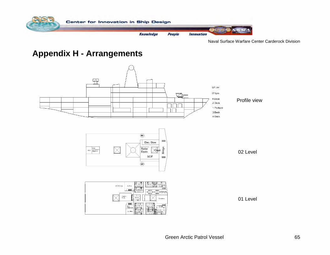
Naval Surface Warfare Center Carderock Division
Green Arctic Patrol Vessel 65
Appendix H - Arrangements
02 Level
01 Level
Profile view
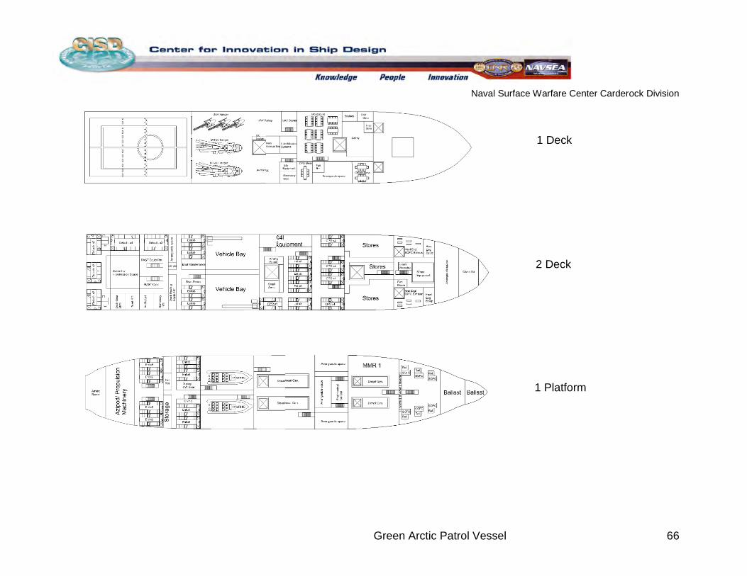
Naval Surface Warfare Center Carderock Division
Green Arctic Patrol Vessel 66
1 Deck
2 Deck
1 Platform
1 Deck
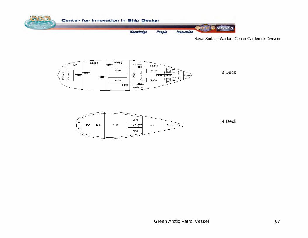
Naval Surface Warfare Center Carderock Division
Green Arctic Patrol Vessel 67
3 Deck
4 Deck
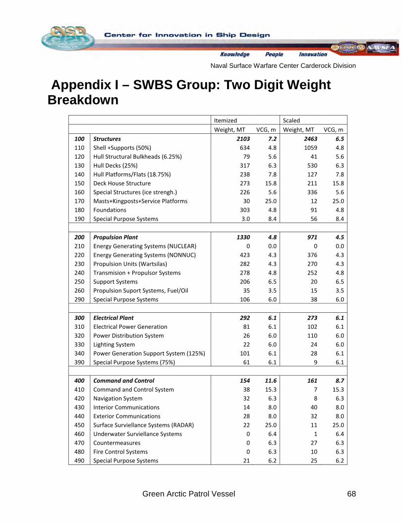
Naval Surface Warfare Center Carderock Division
Green Arctic Patrol Vessel 68
Appendix I – SWBS Group: Two Digit Weight Breakdown
Itemized Scaled Weight, MT VCG, m Weight, MT VCG, m
100 Structures 2103 7.2 2463 6.5 110 Shell +Supports (50%) 634 4.8 1059 4.8 120 Hull Structural Bulkheads (6.25%) 79 5.6 41 5.6 130 Hull Decks (25%) 317 6.3 530 6.3 140 Hull Platforms/Flats (18.75%) 238 7.8 127 7.8 150 Deck House Structure 273 15.8 211 15.8 160 Special Structures (ice strengh.) 226 5.6 336 5.6 170 Masts+Kingposts+Service Platforms 30 25.0 12 25.0 180 Foundations 303 4.8 91 4.8 190 Special Purpose Systems 3.0 8.4 56 8.4
200 Propulsion Plant 1330 4.8 971 4.5 210 Energy Generating Systems (NUCLEAR) 0 0.0 0 0.0 220 Energy Generating Systems (NONNUC) 423 4.3 376 4.3 230 Propulsion Units (Wartsilas) 282 4.3 270 4.3 240 Transmision + Propulsor Systems 278 4.8 252 4.8 250 Support Systems 206 6.5 20 6.5 260 Propulsion Suport Systems, Fuel/Oil 35 3.5 15 3.5 290 Special Purpose Systems 106 6.0 38 6.0
300 Electrical Plant 292 6.1 273 6.1 310 Electrical Power Generation 81 6.1 102 6.1 320 Power Distribution System 26 6.0 110 6.0 330 Lighting System 22 6.0 24 6.0 340 Power Generation Support System (125%) 101 6.1 28 6.1 390 Special Purpose Systems (75%) 61 6.1 9 6.1
400 Command and Control 154 11.6 161 8.7 410 Command and Control System 38 15.3 7 15.3 420 Navigation System 32 6.3 8 6.3 430 Interior Communications 14 8.0 40 8.0 440 Exterior Communications 28 8.0 32 8.0 450 Surface Surviellance Systems (RADAR) 22 25.0 11 25.0 460 Underwater Surviellance Systems 0 6.4 1 6.4 470 Countermeasures 0 6.3 27 6.3 480 Fire Control Systems 0 6.3 10 6.3 490 Special Purpose Systems 21 6.2 25 6.2
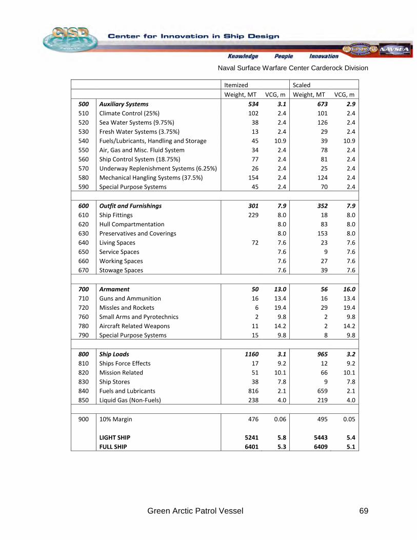
Naval Surface Warfare Center Carderock Division
Green Arctic Patrol Vessel 69
Itemized Scaled Weight, MT VCG, m Weight, MT VCG, m
500 Auxiliary Systems 534 3.1 673 2.9 510 Climate Control (25%) 102 2.4 101 2.4 520 Sea Water Systems (9.75%) 38 2.4 126 2.4 530 Fresh Water Systems (3.75%) 13 2.4 29 2.4 540 Fuels/Lubricants, Handling and Storage 45 10.9 39 10.9 550 Air, Gas and Misc. Fluid System 34 2.4 78 2.4 560 Ship Control System (18.75%) 77 2.4 81 2.4 570 Underway Replenishment Systems (6.25%) 26 2.4 25 2.4 580 Mechanical Hangling Systems (37.5%) 154 2.4 124 2.4 590 Special Purpose Systems 45 2.4 70 2.4
600 Outfit and Furnishings 301 7.9 352 7.9 610 Ship Fittings 229 8.0 18 8.0 620 Hull Compartmentation 8.0 83 8.0 630 Preservatives and Coverings 8.0 153 8.0 640 Living Spaces 72 7.6 23 7.6 650 Service Spaces 7.6 9 7.6 660 Working Spaces 7.6 27 7.6 670 Stowage Spaces 7.6 39 7.6
700 Armament 50 13.0 56 16.0 710 Guns and Ammunition 16 13.4 16 13.4 720 Missles and Rockets 6 19.4 29 19.4 760 Small Arms and Pyrotechnics 2 9.8 2 9.8 780 Aircraft Related Weapons 11 14.2 2 14.2 790 Special Purpose Systems 15 9.8 8 9.8
800 Ship Loads 1160 3.1 965 3.2 810 Ships Force Effects 17 9.2 12 9.2 820 Mission Related 51 10.1 66 10.1 830 Ship Stores 38 7.8 9 7.8 840 Fuels and Lubricants 816 2.1 659 2.1 850 Liquid Gas (Non-Fuels) 238 4.0 219 4.0
900 10% Margin 476 0.06 495 0.05
LIGHT SHIP 5241 5.8 5443 5.4 FULL SHIP 6401 5.3 6409 5.1
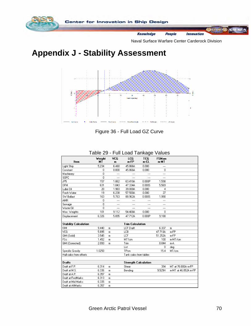
Naval Surface Warfare Center Carderock Division
Green Arctic Patrol Vessel 70
Appendix J - Stability Assessment
Figure 36 - Full Load GZ Curve
Table 29 - Full Load Tankage Values
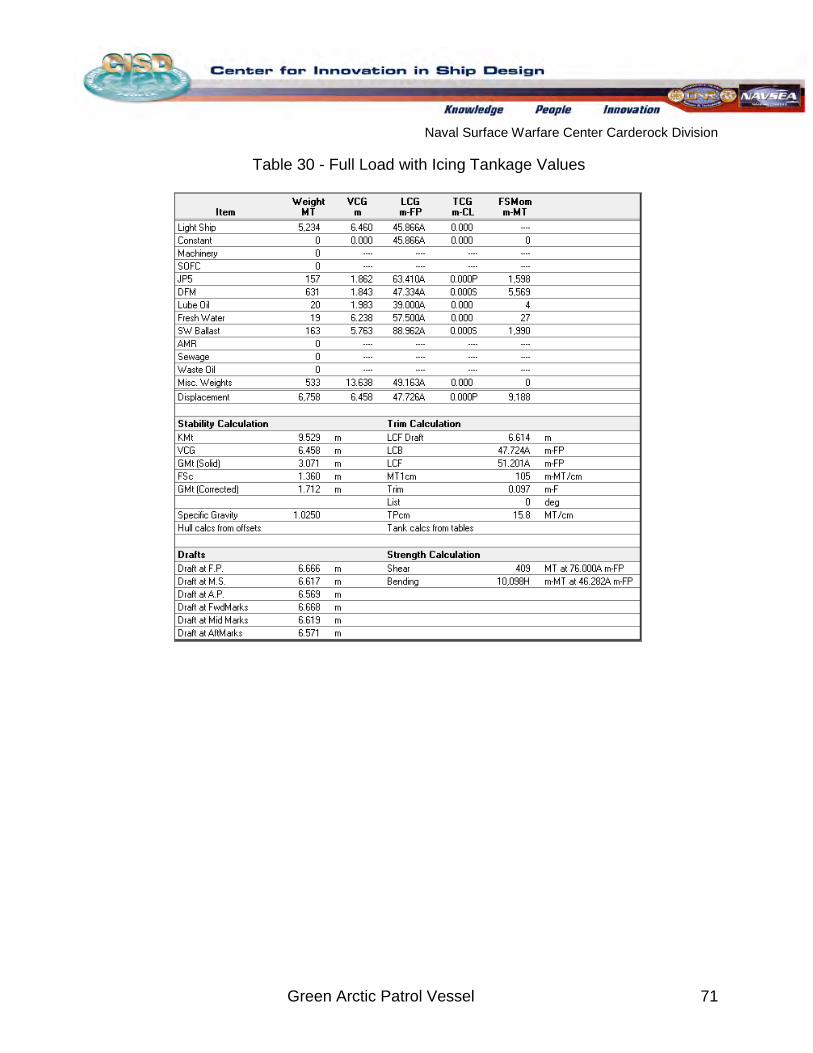
Naval Surface Warfare Center Carderock Division
Green Arctic Patrol Vessel 71
Table 30 - Full Load with Icing Tankage Values
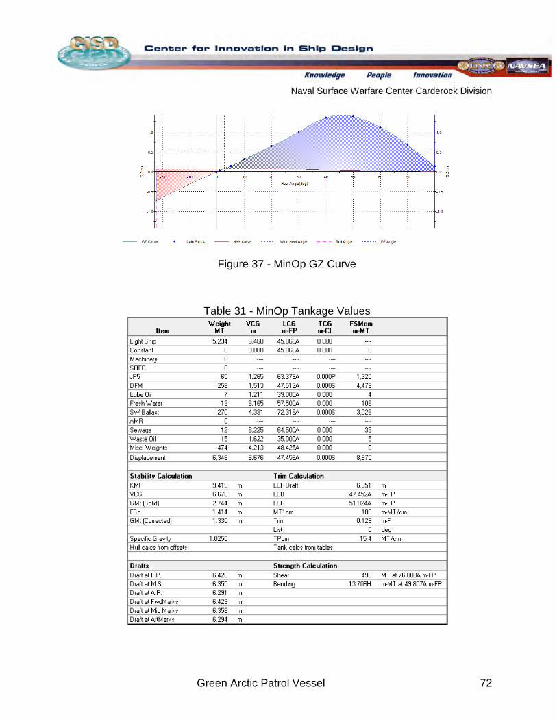
Naval Surface Warfare Center Carderock Division
Green Arctic Patrol Vessel 72
Figure 37 - MinOp GZ Curve
Table 31 - MinOp Tankage Values
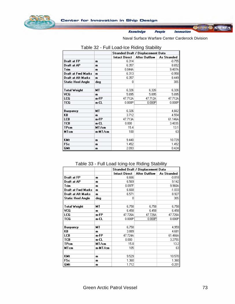
Naval Surface Warfare Center Carderock Division
Green Arctic Patrol Vessel 73
Table 32 - Full Load-Ice Riding Stability
Table 33 - Full Load Icing-Ice Riding Stability
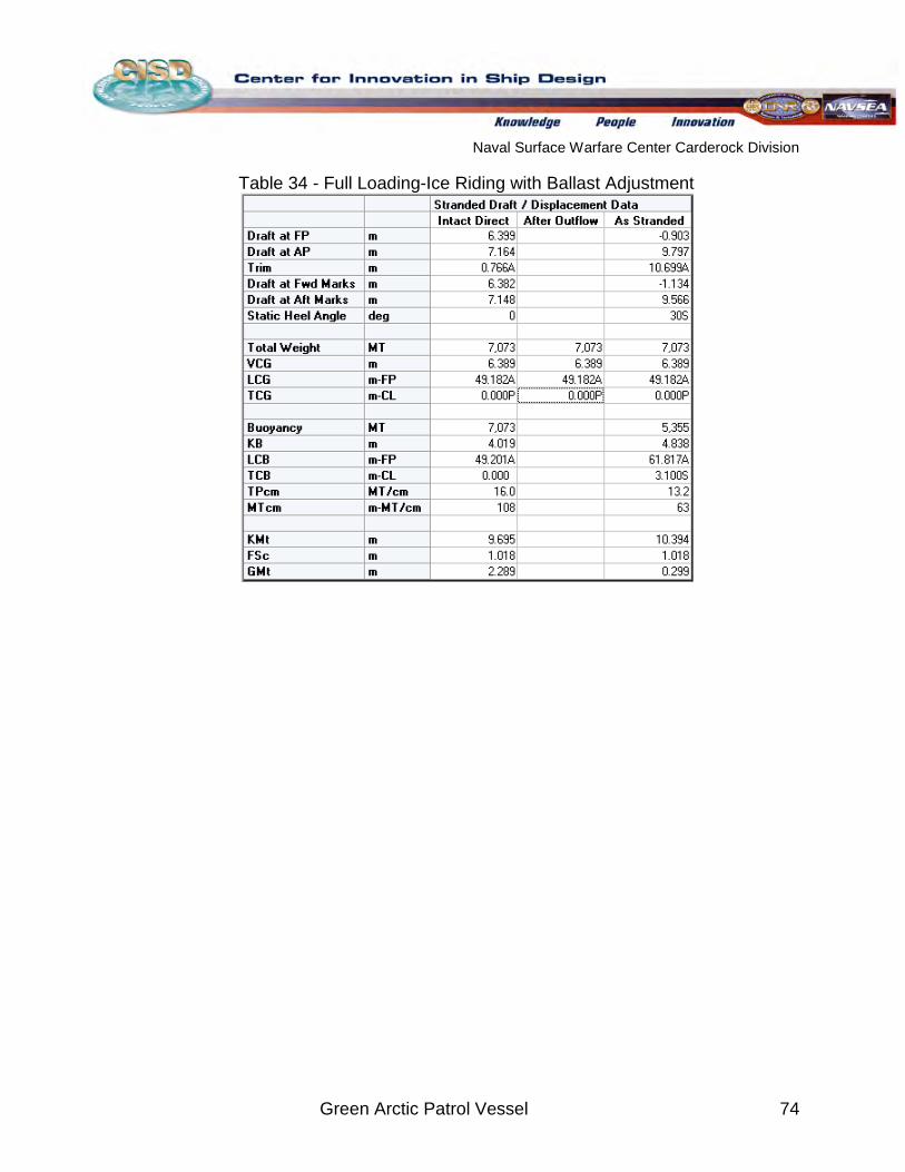
Naval Surface Warfare Center Carderock Division
Green Arctic Patrol Vessel 74
Table 34 - Full Loading-Ice Riding with Ballast Adjustment
Naval Surface Warfare Center Carderock Division
Green Arctic Patrol Vessel 75
Appendix K – Materials Composites are an emerging technology that has seen recent implementations in
U.S. Navy ships. Currently, the ZUMWALT Class destroyer (DDG 1000) is being built that incorporates a superstructure that is entirely made of composite material and is attached to a hull made of steel [30]
The materials used in the final design of the GAPV only include steel. The steel used will be a high strength steel that has been recycled to help promote the “green” theme of the ship. Composites were not implemented for many reasons. The main reason is that composite materials have not been tested in the Arctic and therefore, limited information is available on whether it will have the capability to withstand the harsh climate conditions. It is assumed that composites will not be tested and ready for implementation for a Navy ship by 2030. In addition, all the ice class ships that we based our design on are made of steel and thus it is a proven material for the Arctic. Another reason is that composites materials are extremely high in cost compared to steel due to high raw material costs and high labor content
. Composite materials propose benefits in reduced weight, high tensile strength, reduced radar detection and a low thermal conductivity. In naval operations, the reduced weight is the biggest advantage to incorporating composites because it can substantially improve the fuel consumption of a vessel. In addition, since the vessel has better fuel consumption, the vessels can carry less fuel onboard which further decreases the overall weight of the vessel. Sticking with the “green” theme, the GAPV can benefit largely from this because the ship would require less propulsion power which would gain an increase in fuel savings and lower emissions. Likewise, composite material would help improve the stealth capabilities of the GAPV from submarines with reduced radar detection. Composite materials also generally have a lower thermal conductivity than steel. This can be very beneficially for the GAPV superstructure because it would be able to better insulate the ship and lower the heating requirements. While under load and ice-breaking, composite material typically have higher yield stresses and maybe able to handle more loads than a steel could. Therefore, composite materials are an ideal alternative to steel that was considered for the design of GAPV.
[30]. When looking at incorporating a composite superstructure with a steel hull, our research has shown that a complicated joining system is required that is high in cost and is very tough to service 30[ ]
. Likewise, the personnel on the ship would have to be trained and knowledgeable of composite material maintenance and service. Therefore, the entire GAPV will be built out of high strength recycled steel that can withstand ice interactions.