Embed Size (px)
Citation preview

Granular Systems in Microgravity
Michael L. WilsonThe University of TulsaSupported by Research Corporation

Design goals
Measure properties of a diffuse granular system in microgravity
Look for clusteringMeasure ball impacts & pressuresMeasure ball speeds outside clusterDetermine dependence of dynamics on
system density

Microgravity Approaches
KC-135 low-gravity simulation aircraft Flight dates July 23 & 24, 2002 ~40 low gravity periods of ~30 sec. each
NASA-GAS program on Space Shuttle Flight after ~2004 ~1 hour microgravity data
limited by video data storage.

Experimental System
3 digital video cameras are used to record video and pressure data sets. Pressure data saved on digital audio tracks.
Mirrors are used to increase effective optical path length in GAS enclosure.
Energy input to system via mechanical shaker arm.
All components microprocessor controlled. On board power supplied by D-cell battery
pack.

Optical System

JVC DVM80 and JVCDVM90 cameras Mini DV digital video & audio format 520 x 480 video resolution @ 30 fps 2 channel 16 bit audio @ 48 kHz
400 mm f.l. achromat added for short focus
3” square front surface mirror to lengthen optical path
Sapphire walled box containing ballsBlue high brightness LED lights

Image Analysis
Cluster and individual ball positions determined using codes written in IDL.
Balls tracked from frame to frame to determine velocities.
Velocities determined only in diffuse regions of cells due to image overlap.

Sample Cells

8 sapphire walled sample cells 23.4 x 25.4 x 22.5 mm interior volume
Each has an independent piezoelectric sensor on one face
Each camera sees four cells7 cells are visible by at least one
camera These 7 are filled with brass balls Eighth is left empty as a sensor control

Experiments0.50 mm and/or 1.00 mm grade 200
brassMean free path (mfp) ~Vol./(Nd2)%Oc.Vl. = % of volume occupied by balls
Ball diameter 0.50 mm Ball diameter 1.0 mmCell # #balls mfp (mm) L/mfp %Oc.Vl. Cell # #balls mfp (mm) L/mfp %Oc.Vl.
1 1000 17.1 1.4 0.5 4 250 17.1 1.4 1.02 3100 5.5 4.3 1.5 5 775 5.5 4.3 3.03 10000 1.7 13.9 4.9 6 2500 1.7 13.9 9.87 3100 0.50 mm balls
775 1.00 mm balls 4.5 Cell volume 13400 mm3Mean edge length 23.7 mm
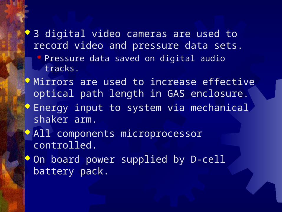
Piezoelectric Impact Sensor

Piezoelectric sensor measures high frequency signal due to individual ball impacts
Recorded data high-pass filtered by D/A converter on camera No direct signal from wall oscillation
Ball impacts cluster when sensor moves into occupied volume
Wall period determined from fft of sensor data

Battery Power System
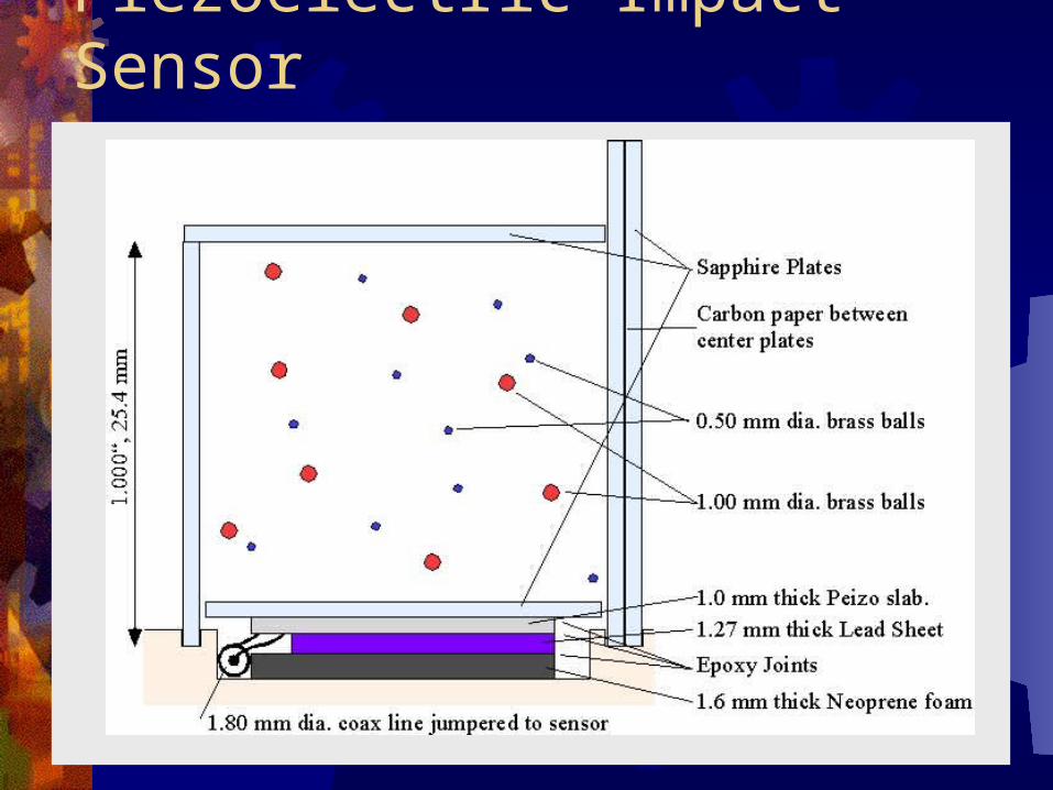
Final output is 8 amps @ 9 volts DC (regulated) for two hours
8 D-dell batteries in series6 strings in parallelAll diode isolated and fusedPVC shroud provides pressure seal
necessary for GAS program

Mechanical Shaker
Amplitude adjusted by changing the effective length of the swing arm. Amplitudes from 0.22 mm to 1.2 mm
Frequency adjusted directly in DC motor Computer control of PWM 9V supply Internal reduction gearing 10:1 Frequency range from 1 to 30 Hz

Design Shaking Values
Typically 20-30 low-g passes per flight
Run# f (Hz) Amp (mm) V (cm/s) Accl (m/s2) Accl/g Larm (") Run# f (Hz) Amp (mm) V (cm/s) Accl (m/s2) Accl/g Larm (") Run# f (Hz) Amp (mm) V (cm/s) Accl (m/s2) Accl/g
1 1 1.1 0.691 0.434 0.044 0.693 21 1.5 1.1 1.037 0.977 0.100 0.693 41 15 1.1 10.367 97.709 9.9702 1 0.72 0.452 0.284 0.029 1.058 22 1.5 0.72 0.679 0.640 0.065 1.058 42 15 0.72 6.786 63.955 6.5263 1 0.48 0.302 0.189 0.019 1.588 23 1.5 0.48 0.452 0.426 0.044 1.588 43 15 0.48 4.524 42.637 4.3514 1 0.31 0.195 0.122 0.012 2.458 24 1.5 0.31 0.292 0.275 0.028 2.458 44 15 0.31 2.922 27.536 2.8105 1 0.22 0.138 0.087 0.009 3.464 25 1.5 0.22 0.207 0.195 0.020 3.464 45 15 0.22 2.073 19.542 1.9946 10 0.22 1.382 8.685 0.886 3.464 26 2.2 0.22 0.304 0.420 0.043 3.464 46 22 0.22 3.041 42.037 4.2897 10 0.31 1.948 12.238 1.249 2.458 27 2.2 0.31 0.429 0.592 0.060 2.458 47 22 0.31 4.285 59.233 6.0448 10 0.48 3.016 18.950 1.934 1.588 28 2.2 0.48 0.664 0.917 0.094 1.588 48 22 0.48 6.635 91.716 9.3599 10 0.72 4.524 28.424 2.900 1.058 29 2.2 0.72 0.995 1.376 0.140 1.058 49 22 0.72 9.953 137.574 14.03810 10 1.1 6.912 43.426 4.431 0.693 30 2.2 1.1 1.521 2.102 0.214 0.693 50 22 1.1 15.205 210.183 21.44711 3 1.1 2.073 3.908 0.399 0.693 31 4.6 1.1 3.179 9.189 0.938 0.693 51 3 1.1 2.073 3.908 0.39912 3 0.72 1.357 2.558 0.261 1.058 32 4.6 0.72 2.081 6.015 0.614 1.058 52 3 0.72 1.357 2.558 0.26113 3 0.48 0.905 1.705 0.174 1.588 33 4.6 0.48 1.387 4.010 0.409 1.588 53 3 0.48 0.905 1.705 0.17414 3 0.31 0.584 1.101 0.112 2.458 34 4.6 0.31 0.896 2.590 0.264 2.458 54 3 0.31 0.584 1.101 0.11215 3 0.22 0.415 0.782 0.080 3.464 35 4.6 0.22 0.636 1.838 0.188 3.464 55 3 0.22 0.415 0.782 0.08016 30 0.22 4.147 78.167 7.976 3.464 36 6.8 0.22 0.940 4.016 0.410 3.464 56 10 0.22 1.382 8.685 0.88617 30 0.31 5.843 110.145 11.239 2.458 37 6.8 0.31 1.324 5.659 0.577 2.458 57 10 0.31 1.948 12.238 1.24918 30 0.48 9.048 170.547 17.403 1.588 38 6.8 0.48 2.051 8.762 0.894 1.588 58 10 0.48 3.016 18.950 1.93419 30 0.72 13.572 255.820 26.104 1.058 39 6.8 0.72 3.076 13.143 1.341 1.058 59 10 0.72 4.524 28.424 2.90020 30 1.1 20.735 390.836 39.881 0.693 40 6.8 1.1 4.700 20.080 2.049 0.693 60 10 1.1 6.912 43.426 4.431

GoalsDetermine the driving conditions
necessary for stability of a free-floating granular cluster
Determine information about internal ball speeds.
Examine energy balance in a real 3-D system
Study dynamics of segregation in 3-DFlight test system for later Space
Shuttle flight opportunity