Embed Size (px)
Citation preview
Grant Agreement N° 215483
Copyright © 2008 by the S-CUBE consortium – All rights reserved.
The research leading to these results has received funding from the European Community's Seventh Framework Programme [FP7/2007-2013] under grant agreement n° 215483 (S-Cube).
File name: CD-IA-2.2.2.pdf
Title: Collection of industrial best practices, scenarios and business cases
Author: POLIMI, Tilburg, City, FBK, UniDue
Editor: Elisabetta Di Nitto, Valentina Mazza, Andrea Mocci (POLIMI)
Reviewers: Andreas Gehlert (UniDue)
Schahram Dustdar (TUW)
Identifier: Deliverable # CD-IA-2.2.2
Type: Deliverable
Version: 1
Date: 27 March 2009
Status: Final
Class: External
Management Summary
The current document aims at presenting the case studies that we have been collecting so far and we consider most relevant to S-Cube. In particular, we focus on five cases as they, collectively, touch all the main points of interest within S-Cube. To make all case studies comparable and easily understood, we have defined a case study description approach that leverages from the results achieved by NEXOF-RA and from the Requirements Engineering literature. The usage of such approach for revising and describing all cases has been very useful to highlight some weak aspects of the original descriptions and to identify those aspects in the case studies that cover the main points of interest for S-Cube.
S-CUBE Deliverable #CD-IA-2.2.2 Software Services and Systems Network
External Final version 1, dated 27 March 2009 Page 2
Members of the S-CUBE consortium:
University of Duisburg-Essen Germany Tilburg University Netherlands City University London U.K. Consiglio Nazionale delle Ricerche Italy Center for Scientific and Technological Research Italy The French National Institute for Research in Computer Science and Control France Lero - The Irish Software Engineering Research Centre Ireland Politecnico di Milano Italy MTA SZTAKI – Computer and Automation Research Institute Hungary Vienna University of Technology Austria Université Claude Bernard Lyon France University of Crete Greece Universidad Politécnica de Madrid Spain University of Stuttgart Germany University of Hamburg Germany VU Amsterdam Netherlands
Published S-CUBE documents These documents are all available from the project website located at http://www.s-cube-network.eu/
S-CubeSoftware Services and Systems Network CD-IA-2.2.2
Contents
1 Introduction 41.1 Context . . . . . . . . . . . . . . . . . . . . . . . . . . . . . . . . . . . . . . . . . . . 41.2 Purpose of the document . . . . . . . . . . . . . . . . . . . . . . . . . . . . . . . . . . 51.3 Structure of the document . . . . . . . . . . . . . . . . . . . . . . . . . . . . . . . . . . 5
2 Requirements for Case Studies 62.1 Description of business situations and presence of agile service networks . . . . . . . . . 62.2 Need for negotiating, establishing, monitoring, enforcing QoS aspects . . . . . . . . . . 62.3 Need for service consumers with various different characteristics . . . . . . . . . . . . . 72.4 Need for distributed infrastructures . . . . . . . . . . . . . . . . . . . . . . . . . . . . . 72.5 Need for highly distributed service compositions . . . . . . . . . . . . . . . . . . . . . 72.6 Highly changing requirements and adaptation at busines, composition, infrastructure levels 8
3 Case study description format 93.1 Introduction . . . . . . . . . . . . . . . . . . . . . . . . . . . . . . . . . . . . . . . . . 93.2 Business Goals and Domain Assumptions Description . . . . . . . . . . . . . . . . . . . 93.3 Domain Description . . . . . . . . . . . . . . . . . . . . . . . . . . . . . . . . . . . . . 103.4 Scenario Description . . . . . . . . . . . . . . . . . . . . . . . . . . . . . . . . . . . . 113.5 Case study description life cycle . . . . . . . . . . . . . . . . . . . . . . . . . . . . . . 12
4 Industrial Case Studies 134.1 Wine Production Case Study . . . . . . . . . . . . . . . . . . . . . . . . . . . . . . . . 144.2 Automotive (360Fresh and IBM) . . . . . . . . . . . . . . . . . . . . . . . . . . . . . . 314.3 EHealth: Complex Diagnostic Workflow (Siemens/Thales) . . . . . . . . . . . . . . . . 424.4 Traffic Management: Large Scale Emergency Handling (Siemens) . . . . . . . . . . . . 574.5 E-Government (TIS/Engineering) . . . . . . . . . . . . . . . . . . . . . . . . . . . . . 67
5 Discussion 76
6 Conclusion 78
External Final Version 1, Dated 27 March 2009 3
S-CubeSoftware Services and Systems Network CD-IA-2.2.2
Chapter 1
Introduction
1.1 Context
The objective of S-Cube is to produce medium-term innovative research results in the area of serviceengineering. Being a network of excellence, S-Cube does not involve industrial partners. This can beseen as an obstacle to the grounding of results achieved by the network on the current best practices andproblems of industry and to the actual experimentation of these results on a concrete basis. To overcomethese issues, S-Cube is fostering links with innovative European large companies and SMEs to formlong-term and productive collaborations. The purpose of workpackage WP-IA-2.2 is exactly to act as adriver for the creation of these links, and in particular:
• To identify alignment needs with industry in order to assess, on the one side, the industrial rele-vance of S-Cube and, on the other side, to gather new needs when they arise.
• To collect industrial best practices and guidelines for SBAs using the empirical evidence possiblyprovided by industrial partners.
• To foster and ensure the acceptance of Service-Based Applications (SBAs) by European industry,also including SMEs.
In concrete terms, the workpackage has started addressing these objectives by trying to collect from in-dustry case studies, challenging problems to address, and best practices. Moreover, the workpackage hasstarted collecting proposals for collaboration on specific problems, and for internships of S-Cube youngresearchers within industry. Finally, the workpackage has also planned to transfer to interested organiza-tions the S-Cube results, and, more specifically, the application of the results on problems proposed byindustry.
Clearly, in this interaction with industry, WP-IA-2.2 is acting as a mediator and is, in turn, interactingwith all the other workpackages in the network. In particular, WP-IA-2.2 is gathering:
• From all research WPs the requirements and expectations for case studies as well as the concreteresults and the application of these results to the case studies.
• From WP-IA-3.1 an overall integrated view of the S-Cube framework. Such a framework will beused to vehiculate to industry the main concepts and challenges S-Cube deals with.
• From the Spread of Excellence (SoE) activity new contacts and possibilities to showcase the resultsto industry.
External Final Version 1, Dated 27 March 2009 4
S-CubeSoftware Services and Systems Network Deliverable # CD-IA-2.2.2
1.2 Purpose of the document
The current document is consistently framed into the roadmap presented in Section 1.1 and aims atpresenting the case studies we have been collecting so far and that we consider most relevant to S-Cube.In particular, we focus on five cases as they, collectively, touch all the main points of interest within S-Cube. These points will be discussed in more detail in the rest of the document and can be summarizedas follows:
• The presence of business situations and, in particular, of Agile Service Networks.
• The need for negotiating, establishing, monitoring, enforcing Quality of Service aspects.
• The presence of actors with different characteristics.
• The presence of a distributed IT infrastructure.
• The possibility of having highly distributed and decentralized service compositions.
• The presence of highly changing requirements that lead to the need of adapting a SBA at variousabstraction levels, from the business level down to the infrastructure.
In order to make all case studies comparable and easy to understand, we have defined a case studydescription approach that leverages from the results achieved by NEXOF-RA [1] and from the Require-ments Engineering literature. The usage of such approach for revising and describing all cases has beenvery useful to highlight inconsistencies and to identify those aspects in the case studies that cover thepoints that we have listed above.
The term case studies has been used in the literature to mean either a specific problem or a problemtogether with a specific solution. In this document we refer to the first meaning as for the moment we areinterested in gathering problems cases that we will then address with our specific S-Cube solutions. Inthe future steps of our work, if available, we could then use the solutions as benchmarks against whichto compare our approaches.
1.3 Structure of the document
This document is structured as follows: Chapter 2 presents the main characteristics that we expect thecase studies shoud have. Such characteristics are the ones that best highlight the most relevant aspectsof S-Cube. Chapter 3 illustrates our methodology for case study description. Chapter 4 presents thecase studies described according to the methodology and Chapter 5 discusses about how the case studiesfulfill the main required characteristics. Finally, Chapter 6 draws the conclusion.
External Final Version 1, Dated 27 March 2009 5
S-CubeSoftware Services and Systems Network CD-IA-2.2.2
Chapter 2
Requirements for Case Studies
This chapter identifies the requirements that should be fulfilled by the industrial case studies in orderto highlight those aspects that are considered important in the S-Cube project. Each of the identifiedrequirements is strictly related to the Challenges of the S-Cube project itself, which are being collectedby IA-3.1 and are going to be presented into the S-Cube white paper.
2.1 Description of business situations and presence of agile service net-works
The next-generation of service-based applications will serve as a mean for developing mission-criticalapplications based on strategic technology capable of creating and executing cross-enterprise collabo-rative business processes, business-aware transactions and connecting the entire business value chains.With a process-managed business value chain, organizations can deploy, monitor and continuously up-date cross-enterprise functions within a mixed environment of people, content and systems. The nextgeneration of service-based applications will essentially provide much more functionality and flexibil-ity, enabling organizations to innovate value delivery systems that transcend the enterprise and extendto every external partner. The trend will be to move from a relatively static view of an organization toa much more dynamic, high-value one, where end-to-end business process interactions and trends areexamined more closely to understand the business dynamics. Such collaborative, complex end-to-endservice interactions give raise to the concept of Agile Service Networks (ASNs). ASNs describe thosesituations where the focus is not on product-centric industries, but rather on the possibility for variousactors to be co-producers and co-innovators of services in a peer to peer way.
Agile Service Networks comprise large numbers of long-running, highly dynamic complex end-to-end service interactions reflecting asynchronous message flows that typically transcend several organi-zations and span geographical locations. The term complex end-to-end service interaction signifies asuccession of automated business processes, which are involved in joint inter-company business conver-sations and transactions across a federation of cooperating organizations.
S-Cube is focusing on the above aspects and will provide a new coherent approach to model, exe-cute, and monitor complex ASNs. Thus, the case studies we envisage should describe some businesscases that involve various organizations that cooperate in a peer to peer way through complex businessconversations and long-term transactions.
2.2 Need for negotiating, establishing, monitoring, enforcing QoS aspects
As illustrated before, more and more services will be provisioned in the context of short-term, volatileand thus highly dynamic relationships and processes involving service providers and requestors (also
External Final Version 1, Dated 27 March 2009 6
S-CubeSoftware Services and Systems Network Deliverable # CD-IA-2.2.2
called consumers) which are not known during design time. Thus, services will have to be enabled tocollaborate in highly distributed environments, cutting across the boundaries of various organizations.
To provide the desired end-to-end quality of such globally distributed service-based applications, thedynamic agreement and assurance of quality becomes a key issue. This requires that not only qualityaspects are negotiated and agreed, but also that these are checked during run-time in order to deter-mine whether there is a need for adapting the service-based application or for re-negotiating the qualitycontracts.
Typically, a contract is a formal agreement between two or more parties to create mutual businessrelations or legal obligations. In electronic settings, contracts are composed of different parts, such asthe definition of business partners, the specification of functional obligations, and quality, price, andpenalties related with the object of the agreement.
In S-Cube approaches to define contracts, to monitor their fulfillment, and to predict potential prob-lems will be studied. Thus, case studies requiring the establishment and management of contracts, willallow us to showcase the results of our work in this area.
2.3 Need for service consumers with various different characteristics
The analysis of the way humans can exploit service compositions and offer services themselves is animportant aspect of S-Cube. In order to exercise the results of such analysis, we expect that case studiesrequire:
• The existence of different types of roles that people can play.
• The presence of different individuals fulfilling the same roles and having different skills and abili-ties. For instance, we can imagine that users of different ages will have different preferences in theway they interact with the system.
• The need for different single and collaborative tasks within business processes.
• The presence of different organizational cultures that might influence qualities of business pro-cesses and service-based applications.
2.4 Need for distributed infrastructures
One of the objectives of S-Cube is to develop service-based solutions that are suitable to support theintegration between distributed business organizations as well as pervasive computing applications. Thisresults in the fact that the underlying software infrastructure we rely on is intrinsically distributed andcomposed of heterogeneous elements.
As a consequence, case studies that can fully benefit from the S-Cube results shall require such adistributed infrastructure. This would allow us to highlight the advantages of distributed and federatedservice repositories and of a communication backbone that enables the interaction between componentson a fully decentralized basis.
2.5 Need for highly distributed service compositions
Service composition with a distributed logic enable an easy implementation of those interaction occurringwithin Agile Service Networks (ASNs) (see Section 2.1). In this setting, the mechanisms that implementASNs should enable the composition of services without the need for a centralized orchestrator thatmanages such composition.
As a consequence, good case studies for S-Cube are those that provide situations where servicecompositions rely on services scattered among different organizations or different parts of the same
External Final Version 1, Dated 27 March 2009 7
S-CubeSoftware Services and Systems Network Deliverable # CD-IA-2.2.2
organization, and where it is appropriate to decentralize the service composition logic. Clearly, casestudies with more limited requirements in terms of distribution of the composition logic would still beaddressable, but they would not highlight the actual advantages offered by S-Cube in this area.
2.6 Highly changing requirements and adaptation at busines, composi-tion, infrastructure levels
We envisage complex case studies where requirements change frequently and, thus, require countinousadaptation. Unpredictable changes might happen at different levels of service-based applications. Forexample, some applications might face changes at infrastructure level (e.g., highly changing network in-frastructure), at composition level (by means of different services dinamically changing their availabilityor QoS aspects), and at business level (dynamic changes in the application requirements).
Case studies requiring changes at all these levels would allow us to show the adaptation and evolutionmechanisms and methods that we plan to develop within S-Cube. Also, we could distinguish betweenthose adaptation needs that are elicited during the design of the system and those that are completelyunforeseen and need to be understood and handled on the fly while the system is running.
External Final Version 1, Dated 27 March 2009 8
S-CubeSoftware Services and Systems Network CD-IA-2.2.2
Chapter 3
Case study description format
3.1 Introduction
Case studies can be described in various ways depending on their purposes. For instance, they candescribe a specific development or proof of concept using a specific technology, or they can simplydescribe an application case without offering a specific implementation solution. Of course, while inthe first case the use case description contains also design, implementation, and even deployment andoperation details, in the second case it should be implementation and technology agnostic. Since, ofcourse, we are thinking of case studies supported by software, the description should focus on whatespectations the software should address more than on how these should be addressed. In other terms,the description should be focusing on eliciting those goals and assumptions that the software shouldaddress.
In this chapter, we introduce a methodology for the description of case studies. We adapt the NEXOF-RA [1] methodology, and add a domain description. The whole description is composed of the followingelements:
• A list of Business Goals and Domain Assumptions for the case study.
• A description of the Case Study Domain;
• A list of Scenario Descriptions;
In the following sections, we detail what we mean by domain and we describe the suggested tem-plates for scenarios, business goals and domain assumptions.
3.2 Business Goals and Domain Assumptions Description
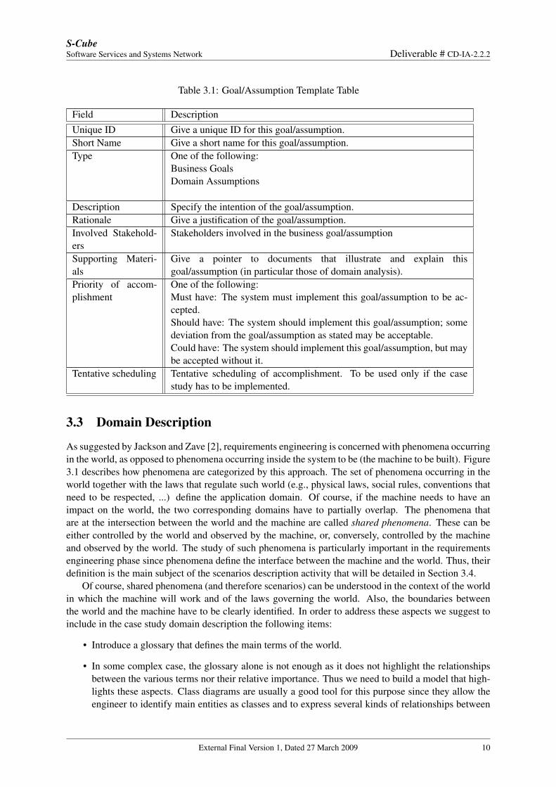
Business Goals and Domain Assumptions express the functionalities and the properties of the machineand of the environment in which it operates. While business goals state what the product has to do orwhat processing action is to take, domain assumptions report properties of the system, or restrictions onthe design of the reference architecture. The following table should be used as a template for any singlebusiness goal and assumption description.
External Final Version 1, Dated 27 March 2009 9
S-CubeSoftware Services and Systems Network Deliverable # CD-IA-2.2.2
Table 3.1: Goal/Assumption Template Table
Field DescriptionUnique ID Give a unique ID for this goal/assumption.Short Name Give a short name for this goal/assumption.Type One of the following:
Business GoalsDomain Assumptions
Description Specify the intention of the goal/assumption.Rationale Give a justification of the goal/assumption.Involved Stakehold-ers
Stakeholders involved in the business goal/assumption
Supporting Materi-als
Give a pointer to documents that illustrate and explain thisgoal/assumption (in particular those of domain analysis).
Priority of accom-plishment
One of the following:Must have: The system must implement this goal/assumption to be ac-cepted.Should have: The system should implement this goal/assumption; somedeviation from the goal/assumption as stated may be acceptable.Could have: The system should implement this goal/assumption, but maybe accepted without it.
Tentative scheduling Tentative scheduling of accomplishment. To be used only if the casestudy has to be implemented.
3.3 Domain Description
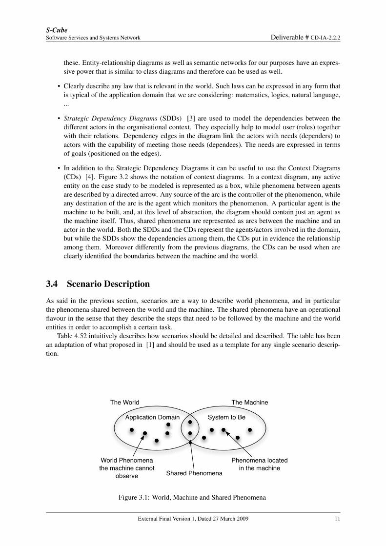
As suggested by Jackson and Zave [2], requirements engineering is concerned with phenomena occurringin the world, as opposed to phenomena occurring inside the system to be (the machine to be built). Figure3.1 describes how phenomena are categorized by this approach. The set of phenomena occurring in theworld together with the laws that regulate such world (e.g., physical laws, social rules, conventions thatneed to be respected, ...) define the application domain. Of course, if the machine needs to have animpact on the world, the two corresponding domains have to partially overlap. The phenomena thatare at the intersection between the world and the machine are called shared phenomena. These can beeither controlled by the world and observed by the machine, or, conversely, controlled by the machineand observed by the world. The study of such phenomena is particularly important in the requirementsengineering phase since phenomena define the interface between the machine and the world. Thus, theirdefinition is the main subject of the scenarios description activity that will be detailed in Section 3.4.
Of course, shared phenomena (and therefore scenarios) can be understood in the context of the worldin which the machine will work and of the laws governing the world. Also, the boundaries betweenthe world and the machine have to be clearly identified. In order to address these aspects we suggest toinclude in the case study domain description the following items:
• Introduce a glossary that defines the main terms of the world.
• In some complex case, the glossary alone is not enough as it does not highlight the relationshipsbetween the various terms nor their relative importance. Thus we need to build a model that high-lights these aspects. Class diagrams are usually a good tool for this purpose since they allow theengineer to identify main entities as classes and to express several kinds of relationships between
External Final Version 1, Dated 27 March 2009 10
S-CubeSoftware Services and Systems Network Deliverable # CD-IA-2.2.2
these. Entity-relationship diagrams as well as semantic networks for our purposes have an expres-sive power that is similar to class diagrams and therefore can be used as well.
• Clearly describe any law that is relevant in the world. Such laws can be expressed in any form thatis typical of the application domain that we are considering: matematics, logics, natural language,...
• Strategic Dependency Diagrams (SDDs) [3] are used to model the dependencies between thedifferent actors in the organisational context. They especially help to model user (roles) togetherwith their relations. Dependency edges in the diagram link the actors with needs (dependers) toactors with the capability of meeting those needs (dependees). The needs are expressed in termsof goals (positioned on the edges).
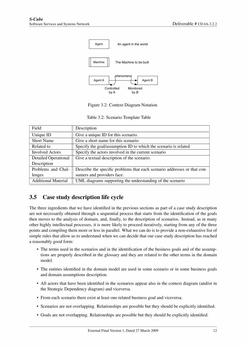
• In addition to the Strategic Dependency Diagrams it can be useful to use the Context Diagrams(CDs) [4]. Figure 3.2 shows the notation of context diagrams. In a context diagram, any activeentity on the case study to be modeled is represented as a box, while phenomena between agentsare described by a directed arrow. Any source of the arc is the controller of the phenomenon, whileany destination of the arc is the agent which monitors the phenomenon. A particular agent is themachine to be built, and, at this level of abstraction, the diagram should contain just an agent asthe machine itself. Thus, shared phenomena are represented as arcs between the machine and anactor in the world. Both the SDDs and the CDs represent the agents/actors involved in the domain,but while the SDDs show the dependencies among them, the CDs put in evidence the relationshipamong them. Moreover differently from the previous diagrams, the CDs can be used when areclearly identified the boundaries between the machine and the world.
3.4 Scenario Description
As said in the previous section, scenarios are a way to describe world phenomena, and in particularthe phenomena shared between the world and the machine. The shared phenomena have an operationalflavour in the sense that they describe the steps that need to be followed by the machine and the worldentities in order to accomplish a certain task.
Table 4.52 intuitively describes how scenarios should be detailed and described. The table has beenan adaptation of what proposed in [1] and should be used as a template for any single scenario descrip-tion.
The World The Machine
Phenomena locatedin the machine
Shared Phenomena
World Phenomenathe machine cannot
observe
Application Domain System to Be
Figure 3.1: World, Machine and Shared Phenomena
External Final Version 1, Dated 27 March 2009 11
S-CubeSoftware Services and Systems Network Deliverable # CD-IA-2.2.2
Agent
EntityMachine
Agent A Agent B
An agent in the world
The Machine to be built
Controlled by A
Monitoredby B
phenomena
Figure 3.2: Context Diagram Notation
Table 3.2: Scenario Template Table
Field DescriptionUnique ID Give a unique ID for this scenario.Short Name Give a short name for this scenarioRelated to Specify the goal/assumption ID to which the scenario is relatedInvolved Actors Specify the actors involved in the current scenarioDetailed OperationalDescription
Give a textual description of the scenario.
Problems and Chal-lenges
Describe the specific problems that each scenario addresses or that con-sumers and providers face.
Additional Material UML diagrams supporting the understanding of the scenario
3.5 Case study description life cycle
The three ingredients that we have identified in the previous sections as part of a case study descriptionare not necessarily obtained through a sequential process that starts from the identification of the goalsthen moves to the analysis of domain, and, finally, to the description of scenarios. Instead, as in manyother highly intellectual processes, it is more likely to proceed iteratively, starting from any of the threepoints and compiling them more or less in parallel. What we can do is to provide a non-exhaustive list ofsimple rules that allow us to understand when we can decide that our case study description has reacheda reasonably good form:
• The terms used in the scenarios and in the identification of the business goals and of the assump-tions are properly described in the glossary and they are related to the other terms in the domainmodel.
• The entities identified in the domain model are used in some scenario or in some business goalsand domain assumptions description.
• All actors that have been identified in the scenarios appear also in the context diagram (and/or inthe Strategic Dependency diagram) and viceversa.
• From each scenario there exist at least one related business goal and viceversa.
• Scenarios are not overlapping. Relationships are possible but they should be explicitly identified.
• Goals are not overlapping. Relationships are possible but they should be explicitly identified.
External Final Version 1, Dated 27 March 2009 12
S-CubeSoftware Services and Systems Network CD-IA-2.2.2
Chapter 4
Industrial Case Studies
This chapter will provide the description of five significant industrial case studies. The first one is focusedon vineyard management and wine production (see Section 4.1) and has been offered by a well-knownItalian wine production company called Donnafugata [5]. This case study is shared with the Artdecoproject [6], partially founded by the Italian Ministery of Education.
The second case study is focused on a complex and geographically distributed supply chain in theautomotive sector (see Section 4.2) and has been offered by researchers of the companies 360Fresh andIBM [7].
The remaining three case studies have been offered by the partners of the NEXOF-RA project [1] andconcern the following areas:
• E-Health and, in particular, the management of Complex Diagnostic Workflows (see Section 4.3).
• Traffic Management (Section 4.4).
• E-Government (Section 4.5).
Every case study has been adapted to the description format previously described in Section 3. In particu-lar, we had to elicit real business goals and domain assumptions from the case studies under examinationsas they were not made explicit. In doing this work we have also identified some repetitions and incon-sistencies that we have eliminated, as well as some implicit actors and some explicitly mentioned actorswho did not have any specific role in the use cases description. Clearly, as we started from the NEXOF fordescribing scenarions, the case studies owned by this project where already partially described accordingto the format we wanted to apply. However, the definition of the application domain was left implicitand we have elicited it from the information collected within scenarios. Moreover, an in depth analyisof these case studies has allowed us to exclude some of the proposed requirements as they were too highlevel and applicable to any service-oriented application.
External Final Version 1, Dated 27 March 2009 13
S-CubeSoftware Services and Systems Network Deliverable # CD-IA-2.2.2
4.1 Wine Production Case Study
Context
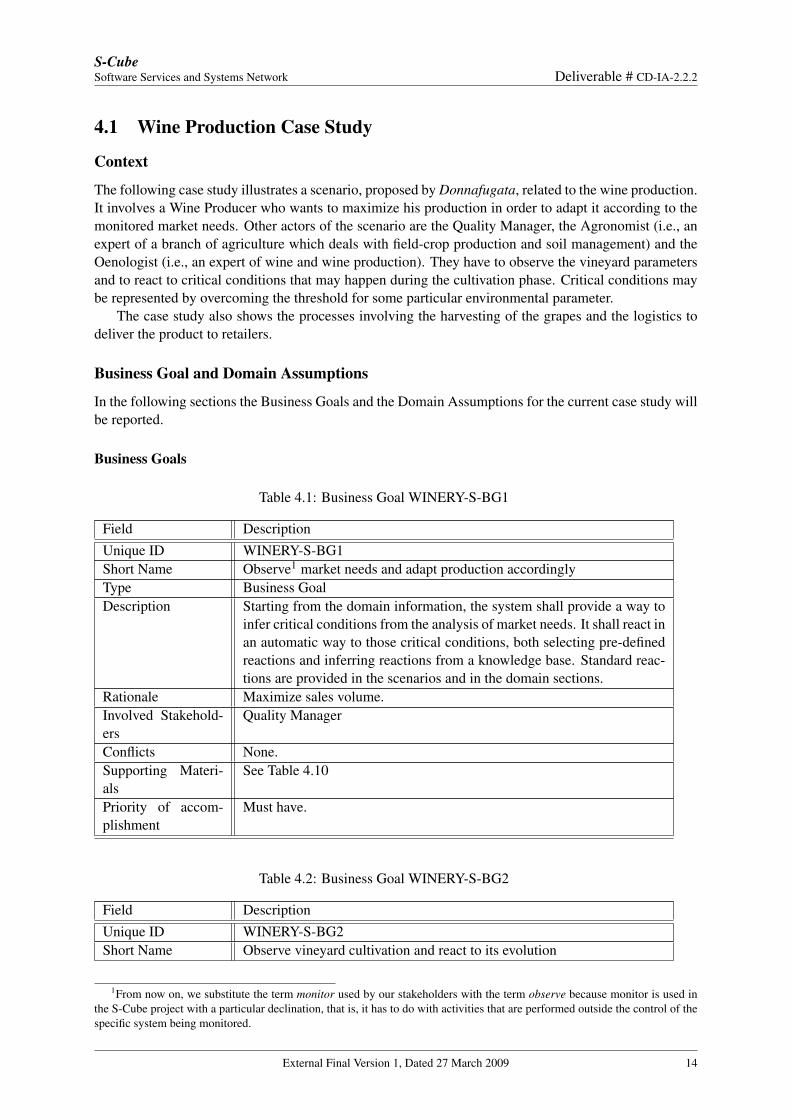
The following case study illustrates a scenario, proposed by Donnafugata, related to the wine production.It involves a Wine Producer who wants to maximize his production in order to adapt it according to themonitored market needs. Other actors of the scenario are the Quality Manager, the Agronomist (i.e., anexpert of a branch of agriculture which deals with field-crop production and soil management) and theOenologist (i.e., an expert of wine and wine production). They have to observe the vineyard parametersand to react to critical conditions that may happen during the cultivation phase. Critical conditions maybe represented by overcoming the threshold for some particular environmental parameter.
The case study also shows the processes involving the harvesting of the grapes and the logistics todeliver the product to retailers.
Business Goal and Domain Assumptions
In the following sections the Business Goals and the Domain Assumptions for the current case study willbe reported.
Business Goals
Table 4.1: Business Goal WINERY-S-BG1
Field DescriptionUnique ID WINERY-S-BG1Short Name Observe1 market needs and adapt production accordinglyType Business GoalDescription Starting from the domain information, the system shall provide a way to
infer critical conditions from the analysis of market needs. It shall react inan automatic way to those critical conditions, both selecting pre-definedreactions and inferring reactions from a knowledge base. Standard reac-tions are provided in the scenarios and in the domain sections.
Rationale Maximize sales volume.Involved Stakehold-ers
Quality Manager
Conflicts None.Supporting Materi-als
See Table 4.10
Priority of accom-plishment
Must have.
Table 4.2: Business Goal WINERY-S-BG2
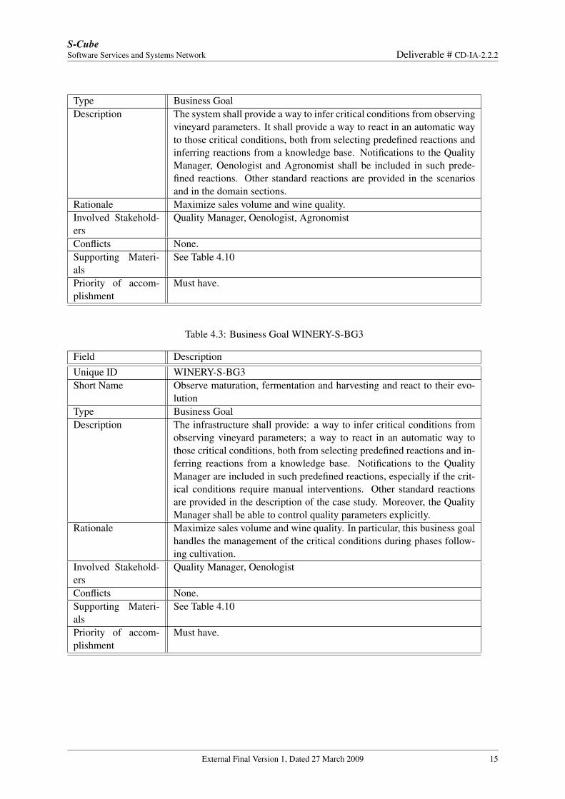
Field DescriptionUnique ID WINERY-S-BG2Short Name Observe vineyard cultivation and react to its evolution
1From now on, we substitute the term monitor used by our stakeholders with the term observe because monitor is used inthe S-Cube project with a particular declination, that is, it has to do with activities that are performed outside the control of thespecific system being monitored.
External Final Version 1, Dated 27 March 2009 14
S-CubeSoftware Services and Systems Network Deliverable # CD-IA-2.2.2
Type Business GoalDescription The system shall provide a way to infer critical conditions from observing
vineyard parameters. It shall provide a way to react in an automatic wayto those critical conditions, both from selecting predefined reactions andinferring reactions from a knowledge base. Notifications to the QualityManager, Oenologist and Agronomist shall be included in such prede-fined reactions. Other standard reactions are provided in the scenariosand in the domain sections.
Rationale Maximize sales volume and wine quality.Involved Stakehold-ers
Quality Manager, Oenologist, Agronomist
Conflicts None.Supporting Materi-als
See Table 4.10
Priority of accom-plishment
Must have.
Table 4.3: Business Goal WINERY-S-BG3
Field DescriptionUnique ID WINERY-S-BG3Short Name Observe maturation, fermentation and harvesting and react to their evo-
lutionType Business GoalDescription The infrastructure shall provide: a way to infer critical conditions from
observing vineyard parameters; a way to react in an automatic way tothose critical conditions, both from selecting predefined reactions and in-ferring reactions from a knowledge base. Notifications to the QualityManager are included in such predefined reactions, especially if the crit-ical conditions require manual interventions. Other standard reactionsare provided in the description of the case study. Moreover, the QualityManager shall be able to control quality parameters explicitly.
Rationale Maximize sales volume and wine quality. In particular, this business goalhandles the management of the critical conditions during phases follow-ing cultivation.
Involved Stakehold-ers
Quality Manager, Oenologist
Conflicts None.Supporting Materi-als
See Table 4.10
Priority of accom-plishment
Must have.
External Final Version 1, Dated 27 March 2009 15
S-CubeSoftware Services and Systems Network Deliverable # CD-IA-2.2.2
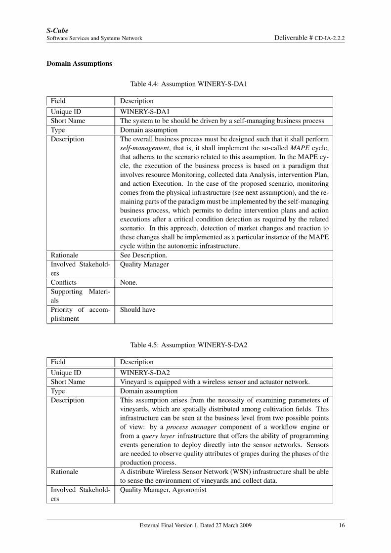
Domain Assumptions
Table 4.4: Assumption WINERY-S-DA1
Field DescriptionUnique ID WINERY-S-DA1Short Name The system to be should be driven by a self-managing business processType Domain assumptionDescription The overall business process must be designed such that it shall perform
self-management, that is, it shall implement the so-called MAPE cycle,that adheres to the scenario related to this assumption. In the MAPE cy-cle, the execution of the business process is based on a paradigm thatinvolves resource Monitoring, collected data Analysis, intervention Plan,and action Execution. In the case of the proposed scenario, monitoringcomes from the physical infrastructure (see next assumption), and the re-maining parts of the paradigm must be implemented by the self-managingbusiness process, which permits to define intervention plans and actionexecutions after a critical condition detection as required by the relatedscenario. In this approach, detection of market changes and reaction tothese changes shall be implemented as a particular instance of the MAPEcycle within the autonomic infrastructure.
Rationale See Description.Involved Stakehold-ers
Quality Manager
Conflicts None.Supporting Materi-alsPriority of accom-plishment
Should have
Table 4.5: Assumption WINERY-S-DA2
Field DescriptionUnique ID WINERY-S-DA2Short Name Vineyard is equipped with a wireless sensor and actuator network.Type Domain assumptionDescription This assumption arises from the necessity of examining parameters of
vineyards, which are spatially distributed among cultivation fields. Thisinfrastructure can be seen at the business level from two possible pointsof view: by a process manager component of a workflow engine orfrom a query layer infrastructure that offers the ability of programmingevents generation to deploy directly into the sensor networks. Sensorsare needed to observe quality attributes of grapes during the phases of theproduction process.
Rationale A distribute Wireless Sensor Network (WSN) infrastructure shall be ableto sense the environment of vineyards and collect data.
Involved Stakehold-ers
Quality Manager, Agronomist
External Final Version 1, Dated 27 March 2009 16
S-CubeSoftware Services and Systems Network Deliverable # CD-IA-2.2.2
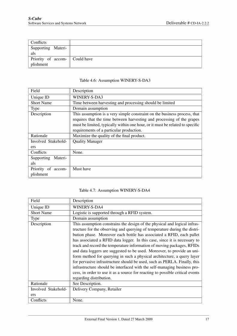
ConflictsSupporting Materi-alsPriority of accom-plishment
Could have
Table 4.6: Assumption WINERY-S-DA3
Field DescriptionUnique ID WINERY-S-DA3Short Name Time between harvesting and processing should be limitedType Domain assumptionDescription This assumption is a very simple constraint on the business process, that
requires that the time between harvesting and processing of the grapesmust be limited, typically within one hour, or it must be related to specificrequirements of a particular production.
Rationale Maximize the quality of the final product.Involved Stakehold-ers
Quality Manager
Conflicts None.Supporting Materi-alsPriority of accom-plishment
Must have
Table 4.7: Assumption WINERY-S-DA4
Field DescriptionUnique ID WINERY-S-DA4Short Name Logistic is supported through a RFID system.Type Domain assumptionDescription This assumption constrains the design of the physical and logical infras-
tructure for the observing and querying of temperature during the distri-bution phase. Moreover each bottle has associated a RFID, each pallethas associated a RFID data logger. In this case, since it is necessary totrack and record the temperature information of moving packages, RFIDsand data loggers are suggested to be used. Moreover, to provide an uni-form method for querying in such a physical architecture, a query layerfor pervasive infrastructure should be used, such as PERLA. Finally, thisinfrastructure should be interfaced with the self-managing business pro-cess, in order to use it as a source for reacting to possible critical eventsregarding distribution.
Rationale See Description.Involved Stakehold-ers
Delivery Company, Retailer
Conflicts None.
External Final Version 1, Dated 27 March 2009 17
S-CubeSoftware Services and Systems Network Deliverable # CD-IA-2.2.2
Supporting Materi-alsPriority of accom-plishment
Could have
Domain Analysis
Strategic Dependency Model and Context Diagram
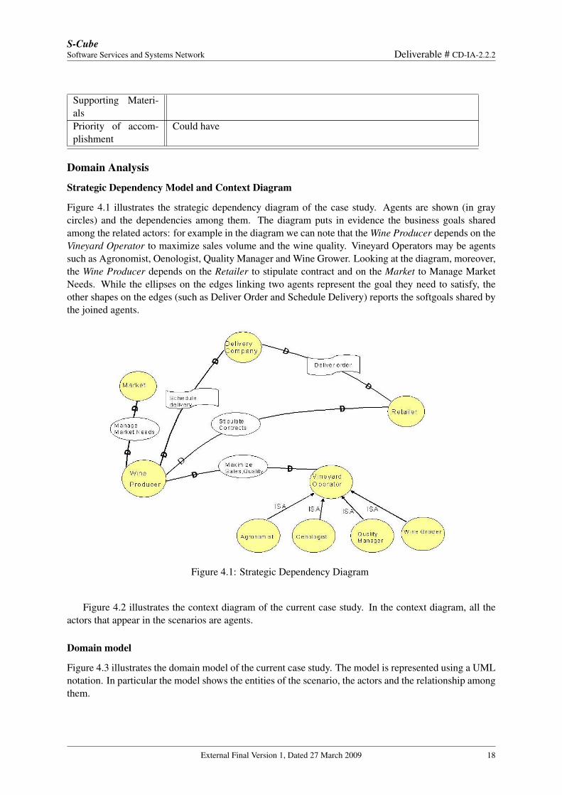
Figure 4.1 illustrates the strategic dependency diagram of the case study. Agents are shown (in graycircles) and the dependencies among them. The diagram puts in evidence the business goals sharedamong the related actors: for example in the diagram we can note that the Wine Producer depends on theVineyard Operator to maximize sales volume and the wine quality. Vineyard Operators may be agentssuch as Agronomist, Oenologist, Quality Manager and Wine Grower. Looking at the diagram, moreover,the Wine Producer depends on the Retailer to stipulate contract and on the Market to Manage MarketNeeds. While the ellipses on the edges linking two agents represent the goal they need to satisfy, theother shapes on the edges (such as Deliver Order and Schedule Delivery) reports the softgoals shared bythe joined agents.
Figure 4.1: Strategic Dependency Diagram
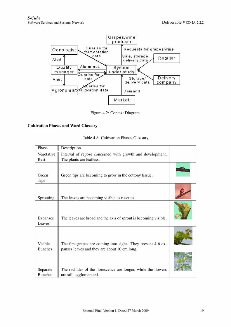
Figure 4.2 illustrates the context diagram of the current case study. In the context diagram, all theactors that appear in the scenarios are agents.
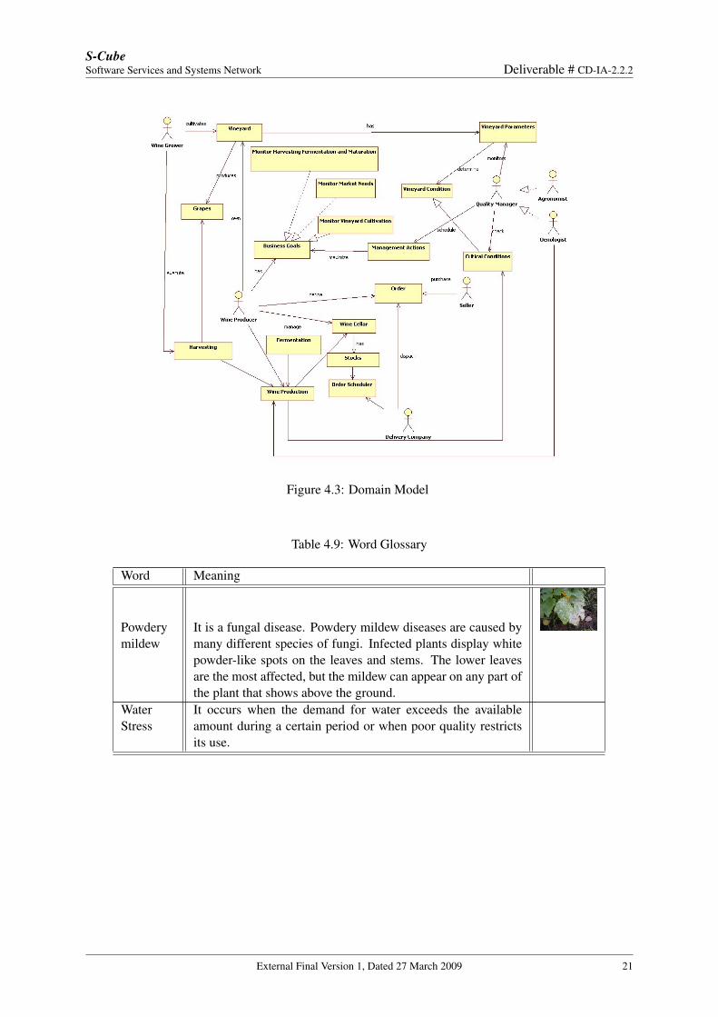
Domain model
Figure 4.3 illustrates the domain model of the current case study. The model is represented using a UMLnotation. In particular the model shows the entities of the scenario, the actors and the relationship amongthem.
External Final Version 1, Dated 27 March 2009 18
S-CubeSoftware Services and Systems Network Deliverable # CD-IA-2.2.2
Figure 4.2: Context Diagram
Cultivation Phases and Word Glossary
Table 4.8: Cultivation Phases Glossary
Phase DescriptionVegetativeRest
Interval of repose concerned with growth and development.The plants are leafless.
GreenTips
Green tips are becoming to grow in the cottony tissue.
Sprouting The leaves are becoming visible as rosettes.
ExpansesLeaves
The leaves are broad and the axis of sprout is becoming visible.
VisibleBunches
The first grapes are coming into sight. They present 4-6 ex-panses leaves and they are about 10 cm long.
SeparateBunches
The rachides of the florescence are longer, while the flowersare still agglomerated.
External Final Version 1, Dated 27 March 2009 19
S-CubeSoftware Services and Systems Network Deliverable # CD-IA-2.2.2
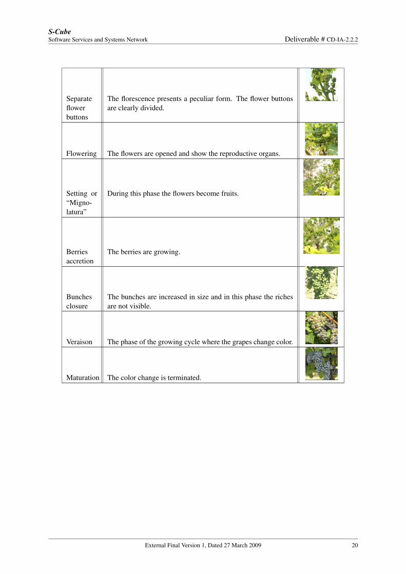
Separateflowerbuttons
The florescence presents a peculiar form. The flower buttonsare clearly divided.
Flowering The flowers are opened and show the reproductive organs.
Setting or“Migno-latura”
During this phase the flowers become fruits.
Berriesaccretion
The berries are growing.
Bunchesclosure
The bunches are increased in size and in this phase the richesare not visible.
Veraison The phase of the growing cycle where the grapes change color.
Maturation The color change is terminated.
External Final Version 1, Dated 27 March 2009 20
S-CubeSoftware Services and Systems Network Deliverable # CD-IA-2.2.2
Figure 4.3: Domain Model
Table 4.9: Word Glossary
Word Meaning
Powderymildew
It is a fungal disease. Powdery mildew diseases are caused bymany different species of fungi. Infected plants display whitepowder-like spots on the leaves and stems. The lower leavesare the most affected, but the mildew can appear on any part ofthe plant that shows above the ground.
WaterStress
It occurs when the demand for water exceeds the availableamount during a certain period or when poor quality restrictsits use.
External Final Version 1, Dated 27 March 2009 21
S-CubeSoftware Services and Systems Network Deliverable # CD-IA-2.2.2
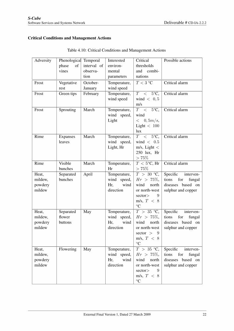
Critical Conditions and Management Actions
Table 4.10: Critical Conditions and Management Actions
Adversity Phenologicalphase ofvines
Temporalinterval ofobserva-tion
Interestedenviron-mentalparameters
Criticalthresholdsand combi-nations
Possible actions
Frost Vegetativerest
October-January
Temperature,wind speed
T < 3 °C Critical alarm
Frost Green tips February Temperature,wind speed
T < 5°C,wind < 0, 5m/s
Critical alarm
Frost Sprouting March Temperature,wind speed,Light
T < 5°C,wind< 0, 5m/s,Light < 100lux
Critical alarm
Rime Expansesleaves
March Temperature,wind speed,Light, Hr
T < 5°C,wind < 0.5m/s, Light <250 lux, Hr> 75%
Critical alarm
Rime Visiblebunches
March Temperature,Hr
T < 5°C, Hr> 75%
Critical alarm
Heat,mildew,powderymildew
Separatedbunches
April Temperature,wind speed,Hr, winddirection
T > 30 °C,Hr > 75%,wind northor north-westsector> 9m/s, T < 8°C
Specific interven-tions for fungaldiseases based onsulphur and copper
Heat,mildew,powderymildew
Separatedflowerbuttons
May Temperature,wind speed,Hr, winddirection
T > 35 °C,Hr > 75%,wind northor north-westsector > 9m/s, T < 8°C
Specific interven-tions for fungaldiseases based onsulphur and copper
Heat,mildew,powderymildew
Flowering May Temperature,wind speed,Hr, winddirection
T > 35 °C,Hr > 75%,wind northor north-westsector> 9m/s, T < 8°C
Specific interven-tions for fungaldiseases based onsulphur and copper
External Final Version 1, Dated 27 March 2009 22
S-CubeSoftware Services and Systems Network Deliverable # CD-IA-2.2.2
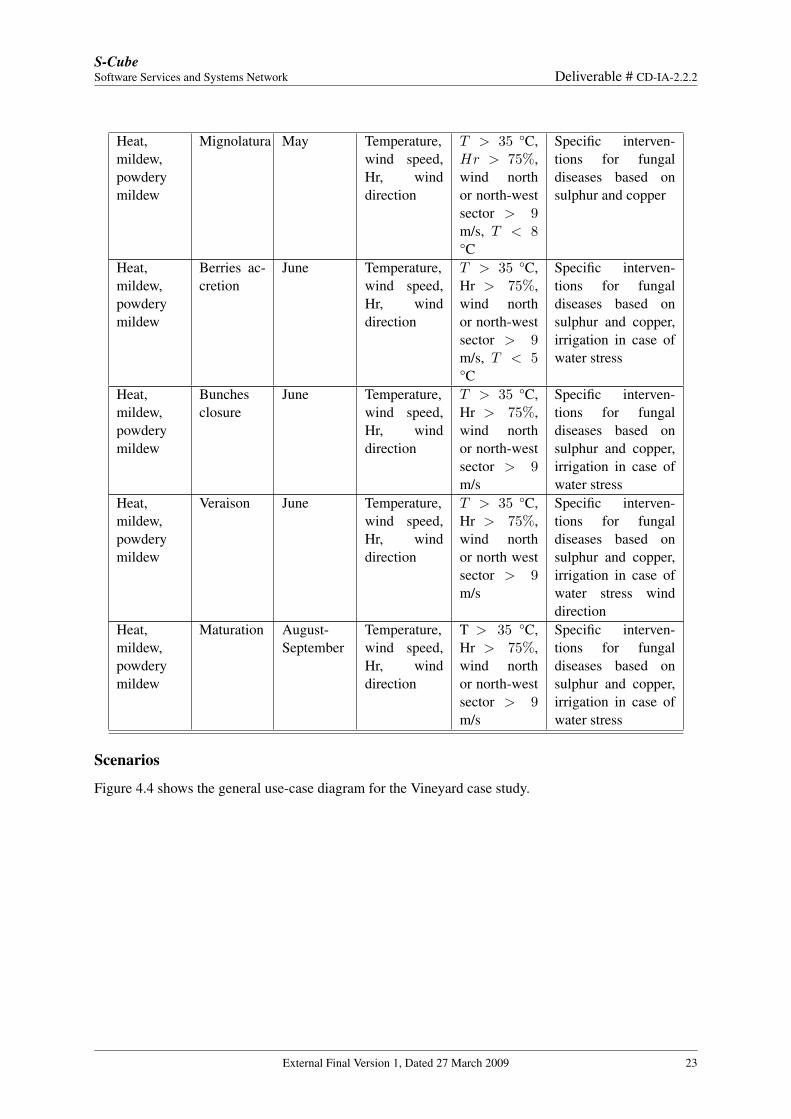
Heat,mildew,powderymildew
Mignolatura May Temperature,wind speed,Hr, winddirection
T > 35 °C,Hr > 75%,wind northor north-westsector > 9m/s, T < 8°C
Specific interven-tions for fungaldiseases based onsulphur and copper
Heat,mildew,powderymildew
Berries ac-cretion
June Temperature,wind speed,Hr, winddirection
T > 35 °C,Hr > 75%,wind northor north-westsector > 9m/s, T < 5°C
Specific interven-tions for fungaldiseases based onsulphur and copper,irrigation in case ofwater stress
Heat,mildew,powderymildew
Bunchesclosure
June Temperature,wind speed,Hr, winddirection
T > 35 °C,Hr > 75%,wind northor north-westsector > 9m/s
Specific interven-tions for fungaldiseases based onsulphur and copper,irrigation in case ofwater stress
Heat,mildew,powderymildew
Veraison June Temperature,wind speed,Hr, winddirection
T > 35 °C,Hr > 75%,wind northor north westsector > 9m/s
Specific interven-tions for fungaldiseases based onsulphur and copper,irrigation in case ofwater stress winddirection
Heat,mildew,powderymildew
Maturation August-September
Temperature,wind speed,Hr, winddirection
T > 35 °C,Hr > 75%,wind northor north-westsector > 9m/s
Specific interven-tions for fungaldiseases based onsulphur and copper,irrigation in case ofwater stress
Scenarios
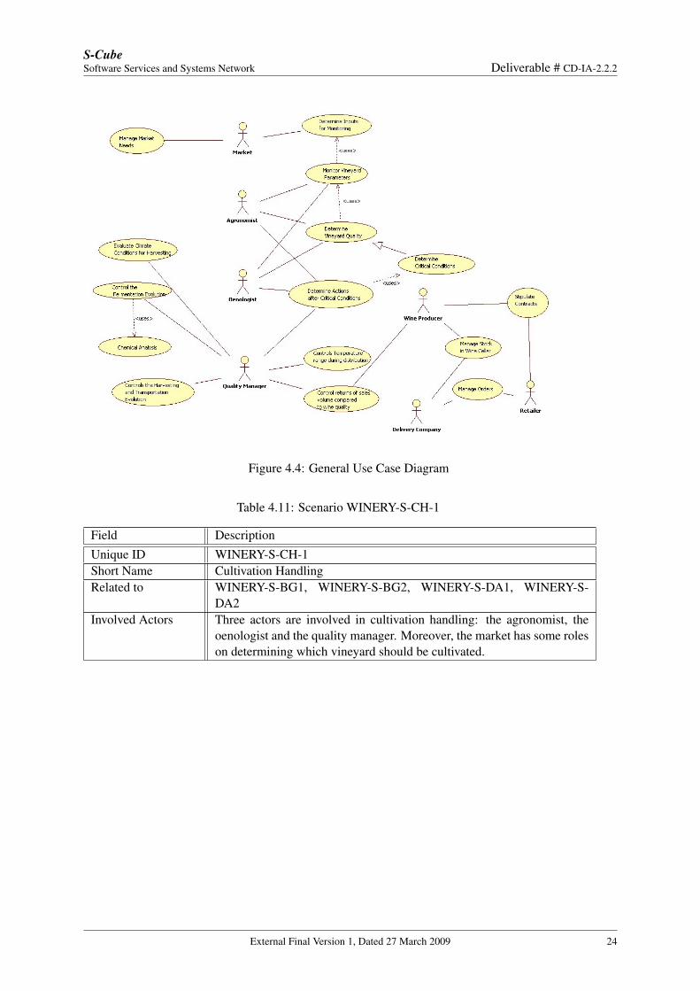
Figure 4.4 shows the general use-case diagram for the Vineyard case study.
External Final Version 1, Dated 27 March 2009 23
S-CubeSoftware Services and Systems Network Deliverable # CD-IA-2.2.2
Figure 4.4: General Use Case Diagram
Table 4.11: Scenario WINERY-S-CH-1
Field DescriptionUnique ID WINERY-S-CH-1Short Name Cultivation HandlingRelated to WINERY-S-BG1, WINERY-S-BG2, WINERY-S-DA1, WINERY-S-
DA2Involved Actors Three actors are involved in cultivation handling: the agronomist, the
oenologist and the quality manager. Moreover, the market has some roleson determining which vineyard should be cultivated.
External Final Version 1, Dated 27 March 2009 24
S-CubeSoftware Services and Systems Network Deliverable # CD-IA-2.2.2
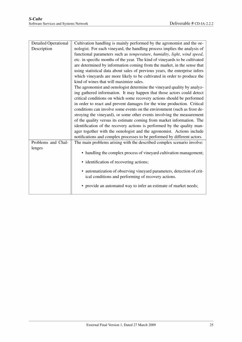
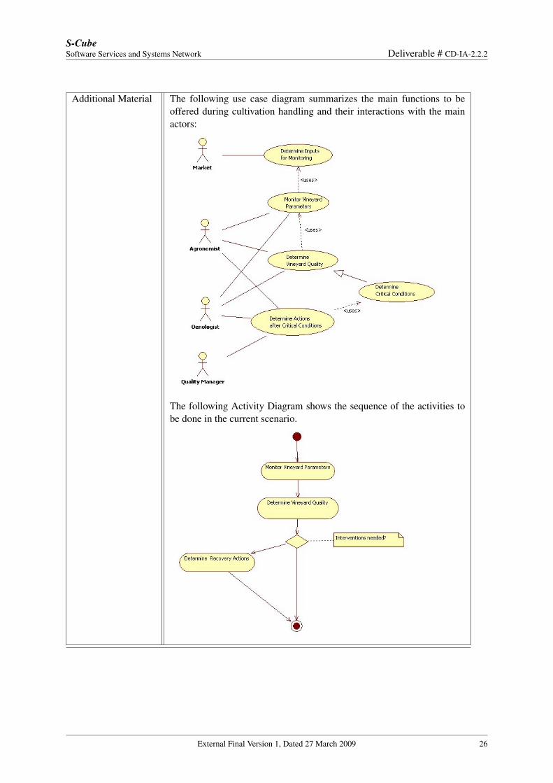
Detailed OperationalDescription
Cultivation handling is mainly performed by the agronomist and the oe-nologist. For each vineyard, the handling process implies the analysis offunctional parameters such as temperature, humidity, light, wind speed,etc. in specific months of the year. The kind of vineyards to be cultivatedare determined by information coming from the market, in the sense thatusing statistical data about sales of previous years, the enterprise inferswhich vineyards are more likely to be cultivated in order to produce thekind of wines that will maximize sales.The agronomist and oenologist determine the vineyard quality by analyz-ing gathered information. It may happen that those actors could detectcritical conditions on which some recovery actions should be performedin order to react and prevent damages for the wine production. Criticalconditions can involve some events on the environment (such as frost de-stroying the vineyard), or some other events involving the measurementof the quality versus its estimate coming from market information. Theidentification of the recovery actions is performed by the quality man-ager together with the oenologist and the agronomist. Actions includenotifications and complex processes to be performed by different actors.
Problems and Chal-lenges
The main problems arising with the described complex scenario involve:
• handling the complex process of vineyard cultivation management;
• identification of recovering actions;
• automatization of observing vineyard parameters, detection of crit-ical conditions and performing of recovery actions.
• provide an automated way to infer an estimate of market needs;
External Final Version 1, Dated 27 March 2009 25
S-CubeSoftware Services and Systems Network Deliverable # CD-IA-2.2.2
Additional Material The following use case diagram summarizes the main functions to beoffered during cultivation handling and their interactions with the mainactors:
The following Activity Diagram shows the sequence of the activities tobe done in the current scenario.
External Final Version 1, Dated 27 March 2009 26
S-CubeSoftware Services and Systems Network Deliverable # CD-IA-2.2.2
Table 4.12: Scenario WINERY-S-CH-2
Field DescriptionUnique ID WINERY-S-CH-2Short Name Managing the Market NeedsRelated to WINERY-S-BG1, WINERY-S-BG2Involved Actors MarketDetailed OperationalDescription
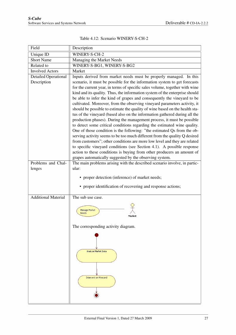
Inputs derived from market needs must be properly managed. In thisscenario, it must be possible for the information system to get forecastsfor the current year, in terms of specific sales volume, together with winekind and its quality. Thus, the information system of the enterprise shouldbe able to infer the kind of grapes and consequently the vineyard to becultivated. Moreover, from the observing vineyard parameters activity, itshould be possible to estimate the quality of wine based on the health sta-tus of the vineyard (based also on the information gathered during all theproduction phases). During the management process, it must be possibleto detect some critical conditions regarding the estimated wine quality.One of those condition is the following: ”the estimated Qs from the ob-serving activity seems to be too much different from the quality Q desiredfrom customers”; other conditions are more low level and they are relatedto specific vineyard conditions (see Section 4.1). A possible responseaction to these conditions is buying from other producers an amount ofgrapes automatically suggested by the observing system.
Problems and Chal-lenges
The main problems arising with the described scenario involve, in partic-ular:
• proper detection (inference) of market needs;
• proper identification of recovering and response actions;
Additional Material The sub use case.
The corresponding activity diagram.
External Final Version 1, Dated 27 March 2009 27
S-CubeSoftware Services and Systems Network Deliverable # CD-IA-2.2.2
Table 4.13: Scenario WINERY-S-HFM
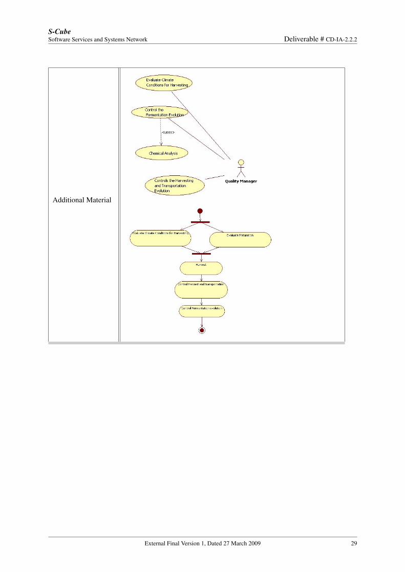
Field DescriptionUnique ID WINERY-S-HFMShort Name Harvesting, Fermentation and MaturationRelated to WINERY-S-DA1, WINERY-S-DA2, WINERY-S-BG3Involved Actors Quality ManagerDetailed OperationalDescription
In those three phases, the quality manager should be helped to controlquality attributes to keep the wine production quality at the required level.The controlled phases are the following:
• Harvesting; is a critical part of the wine production process. Usu-ally, it is necessary to:
−Minimize the interval between harvesting and grapes processing;
− Evaluate climatic conditions for harvesting (depending on theparticular kind of grapes or production, they may require specificclimatic conditions);
• Fermentation:
− Chemical analysis (both “in loco” and in the lab) to monitorquality and avoid critical events, such as high concentration ofacetic acid or presence of dangerous bacteria; those events mustbe properly communicated so that they can be properly managedby manual intervention;
− acidity, humidity and temperature must be recorded in each cel-lar to monitor the quality of the produced wine.
• In any transportation sub-phase, humidity and temperature must beobserved.
Problems and Chal-lenges
The main problems arising with the described complex scenario involve:
• provide a distributed and secure infrastructure for observing criticalparameters, both during fermentation and harvesting;
• monitor critical parameters during any transportation phase;
• minimize the time between harvesting and the grapes processing.
External Final Version 1, Dated 27 March 2009 28
S-CubeSoftware Services and Systems Network Deliverable # CD-IA-2.2.2
Additional Material
External Final Version 1, Dated 27 March 2009 29
S-CubeSoftware Services and Systems Network Deliverable # CD-IA-2.2.2
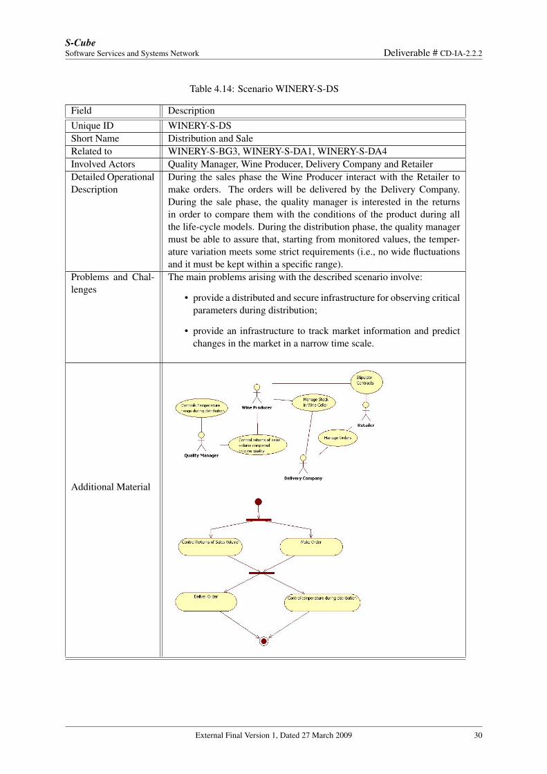
Table 4.14: Scenario WINERY-S-DS
Field DescriptionUnique ID WINERY-S-DSShort Name Distribution and SaleRelated to WINERY-S-BG3, WINERY-S-DA1, WINERY-S-DA4Involved Actors Quality Manager, Wine Producer, Delivery Company and RetailerDetailed OperationalDescription
During the sales phase the Wine Producer interact with the Retailer tomake orders. The orders will be delivered by the Delivery Company.During the sale phase, the quality manager is interested in the returnsin order to compare them with the conditions of the product during allthe life-cycle models. During the distribution phase, the quality managermust be able to assure that, starting from monitored values, the temper-ature variation meets some strict requirements (i.e., no wide fluctuationsand it must be kept within a specific range).
Problems and Chal-lenges
The main problems arising with the described scenario involve:
• provide a distributed and secure infrastructure for observing criticalparameters during distribution;
• provide an infrastructure to track market information and predictchanges in the market in a narrow time scale.
Additional Material
External Final Version 1, Dated 27 March 2009 30
S-CubeSoftware Services and Systems Network Deliverable # CD-IA-2.2.2
4.2 Automotive (360Fresh and IBM)
Context
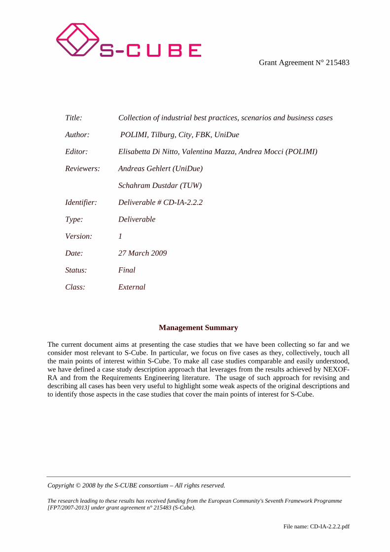
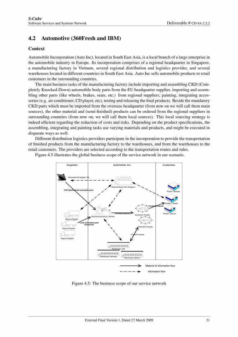
Automobile Incorporation (Auto Inc), located in South East Asia, is a local branch of a large enterprise inthe automobile industry in Europe. Its incorporation comprises of a regional headquarter in Singapore,a manufacturing factory in Vietnam, several regional distribution and logistics provider, and severalwarehouses located in different countries in South East Asia. Auto Inc sells automobile products to retailcustomers in the surrounding countries.
The main business tasks of the manufacturing factory include importing and assembling CKD (Com-pletely Knocked-Down) automobile body parts from the EU headquarter supplier, importing and assem-bling other parts (like wheels, brakes, seats, etc.) from regional suppliers, painting, integrating acces-sories (e.g. air conditioner, CD player, etc), testing and releasing the final products. Beside the mandatoryCKD parts which must be imported from the overseas headquarter (from now on we will call them mainsources), the other material and (semi-finished) products can be ordered from the regional suppliers insurrounding countries (from now on, we will call them local sources). This local sourcing strategy isindeed efficient regarding the reduction of costs and risks. Depending on the product specifications, theassembling, integrating and painting tasks use varying materials and products, and might be executed indisparate ways as well.
Different distribution logistics providers participate in the incorporation to provide the transportationof finished products from the manufacturing factory to the warehouses, and from the warehouses to theretail customers. The providers are selected according to the transportation routes and rules.
Figure 4.5 illustrates the global business scope of the service network in our scenario.
CustomersAutomobile, IncSuppliers
Regional Supplier
Automobile HQ Supplier , EU
Regional Supplier
Distribution ProviderManufacturing factory, Vietnam
Regional Branch HQ, Singapore
Regional Supplier
Retailer, Thailand
Retailer, Vietnam
Retailer, Malaysia
Distribution Provider
Warehouse, Laos
Warehouse, IndonesiaWarehouse, Vietnam
Material & Information flow
Information flow
CKD Semifinished automobile parts
Local automobile parts, accessories
Finished products
Finished Products
Finished Products
Figure 4.5: The business scope of our service network
External Final Version 1, Dated 27 March 2009 31
S-CubeSoftware Services and Systems Network Deliverable # CD-IA-2.2.2
Business Goals and Domain Assumptions
Business Goals
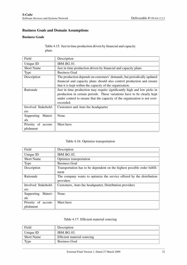
Table 4.15: Just in time production driven by financial and capacityplans
Field DescriptionUnique ID IBM BG 01.Short Name Just in time production driven by financial and capacity plansType Business GoalDescription The production depends on customers’ demands, but periodically updated
financial and capacity plans should also control production and ensurethat it is kept within the capacity of the organization.
Rationale Just in time production may require significantly high and low picks inproduction in certain periods. These variations have to be clearly keptunder control to ensure that the capacity of the organization is not over-exceeded.
Involved Stakehold-ers
Customers and Auto Inc headquarter
Supporting Materi-als
None.
Priority of accom-plishment
Must have
Table 4.16: Optimize transportation
Field DescriptionUnique ID IBM BG 02.Short Name Optimize transportationType Business GoalDescription Transportation has to be dependent on the highest possible order fulfill-
mentRationale The company wants to optimize the service offered by the distribution
providersInvolved Stakehold-ers
Customers, Auto Inc headquarter, Distribution providers
Supporting Materi-als
None.
Priority of accom-plishment
Must have
Table 4.17: Efficient material sourcing
Field DescriptionUnique ID IBM BG 03.Short Name Efficient material sourcingType Business Goal
External Final Version 1, Dated 27 March 2009 32
S-CubeSoftware Services and Systems Network Deliverable # CD-IA-2.2.2
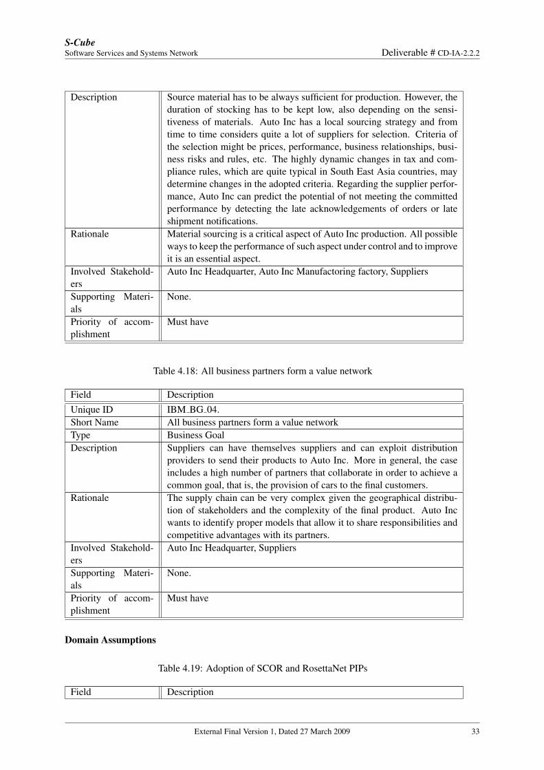
Description Source material has to be always sufficient for production. However, theduration of stocking has to be kept low, also depending on the sensi-tiveness of materials. Auto Inc has a local sourcing strategy and fromtime to time considers quite a lot of suppliers for selection. Criteria ofthe selection might be prices, performance, business relationships, busi-ness risks and rules, etc. The highly dynamic changes in tax and com-pliance rules, which are quite typical in South East Asia countries, maydetermine changes in the adopted criteria. Regarding the supplier perfor-mance, Auto Inc can predict the potential of not meeting the committedperformance by detecting the late acknowledgements of orders or lateshipment notifications.
Rationale Material sourcing is a critical aspect of Auto Inc production. All possibleways to keep the performance of such aspect under control and to improveit is an essential aspect.
Involved Stakehold-ers
Auto Inc Headquarter, Auto Inc Manufactoring factory, Suppliers
Supporting Materi-als
None.
Priority of accom-plishment
Must have
Table 4.18: All business partners form a value network
Field DescriptionUnique ID IBM BG 04.Short Name All business partners form a value networkType Business GoalDescription Suppliers can have themselves suppliers and can exploit distribution
providers to send their products to Auto Inc. More in general, the caseincludes a high number of partners that collaborate in order to achieve acommon goal, that is, the provision of cars to the final customers.
Rationale The supply chain can be very complex given the geographical distribu-tion of stakeholders and the complexity of the final product. Auto Incwants to identify proper models that allow it to share responsibilities andcompetitive advantages with its partners.
Involved Stakehold-ers
Auto Inc Headquarter, Suppliers
Supporting Materi-als
None.
Priority of accom-plishment
Must have
Domain Assumptions
Table 4.19: Adoption of SCOR and RosettaNet PIPs
Field Description
External Final Version 1, Dated 27 March 2009 33
S-CubeSoftware Services and Systems Network Deliverable # CD-IA-2.2.2
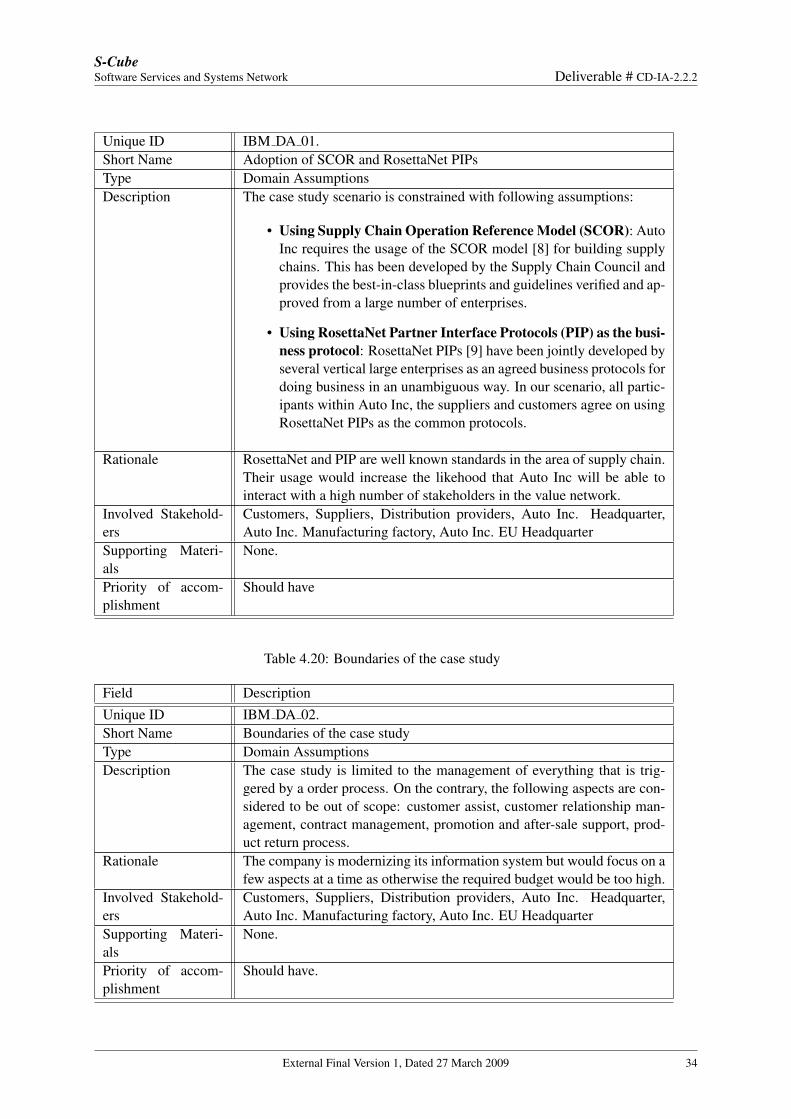
Unique ID IBM DA 01.Short Name Adoption of SCOR and RosettaNet PIPsType Domain AssumptionsDescription The case study scenario is constrained with following assumptions:
• Using Supply Chain Operation Reference Model (SCOR): AutoInc requires the usage of the SCOR model [8] for building supplychains. This has been developed by the Supply Chain Council andprovides the best-in-class blueprints and guidelines verified and ap-proved from a large number of enterprises.
• Using RosettaNet Partner Interface Protocols (PIP) as the busi-ness protocol: RosettaNet PIPs [9] have been jointly developed byseveral vertical large enterprises as an agreed business protocols fordoing business in an unambiguous way. In our scenario, all partic-ipants within Auto Inc, the suppliers and customers agree on usingRosettaNet PIPs as the common protocols.
Rationale RosettaNet and PIP are well known standards in the area of supply chain.Their usage would increase the likehood that Auto Inc will be able tointeract with a high number of stakeholders in the value network.
Involved Stakehold-ers
Customers, Suppliers, Distribution providers, Auto Inc. Headquarter,Auto Inc. Manufacturing factory, Auto Inc. EU Headquarter
Supporting Materi-als
None.
Priority of accom-plishment
Should have
Table 4.20: Boundaries of the case study
Field DescriptionUnique ID IBM DA 02.Short Name Boundaries of the case studyType Domain AssumptionsDescription The case study is limited to the management of everything that is trig-
gered by a order process. On the contrary, the following aspects are con-sidered to be out of scope: customer assist, customer relationship man-agement, contract management, promotion and after-sale support, prod-uct return process.
Rationale The company is modernizing its information system but would focus on afew aspects at a time as otherwise the required budget would be too high.
Involved Stakehold-ers
Customers, Suppliers, Distribution providers, Auto Inc. Headquarter,Auto Inc. Manufacturing factory, Auto Inc. EU Headquarter
Supporting Materi-als
None.
Priority of accom-plishment
Should have.
External Final Version 1, Dated 27 March 2009 34
S-CubeSoftware Services and Systems Network Deliverable # CD-IA-2.2.2
Domain Analysis
Stategic Dependency Model and Context Diagram
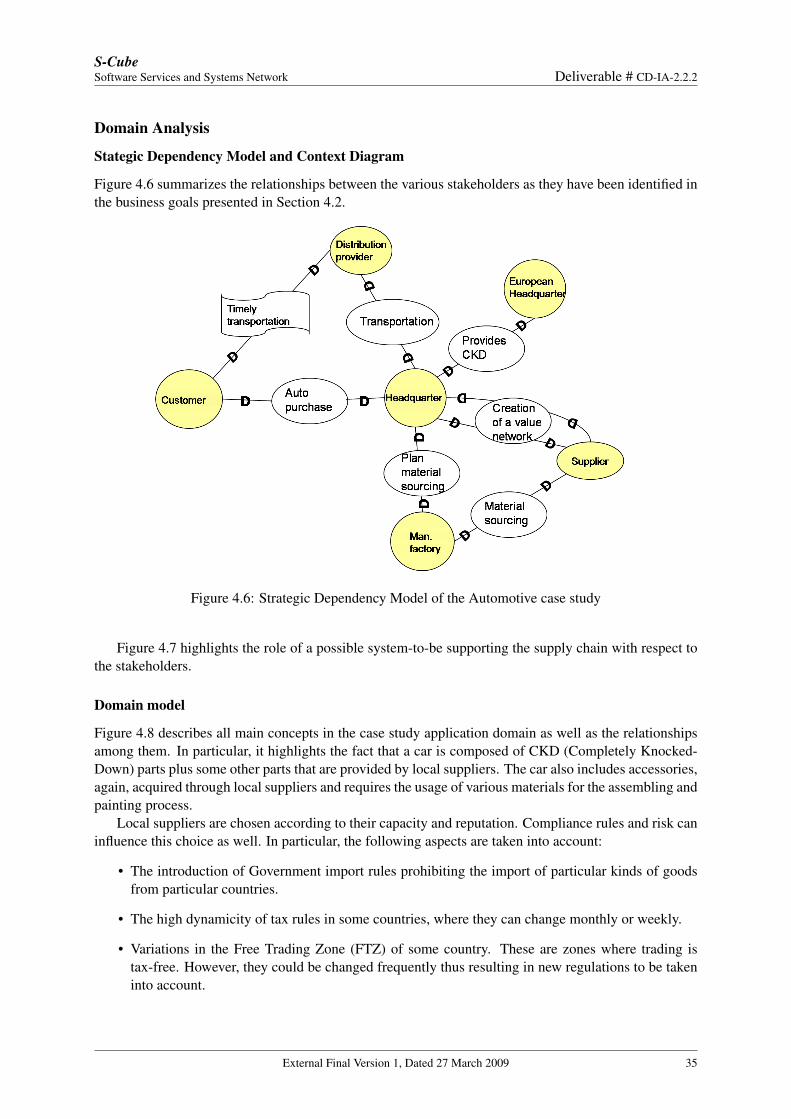
Figure 4.6 summarizes the relationships between the various stakeholders as they have been identified inthe business goals presented in Section 4.2.
Figure 4.6: Strategic Dependency Model of the Automotive case study
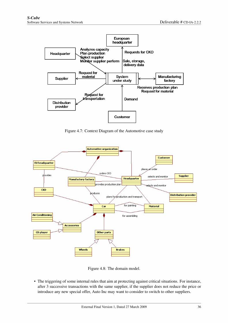
Figure 4.7 highlights the role of a possible system-to-be supporting the supply chain with respect tothe stakeholders.
Domain model
Figure 4.8 describes all main concepts in the case study application domain as well as the relationshipsamong them. In particular, it highlights the fact that a car is composed of CKD (Completely Knocked-Down) parts plus some other parts that are provided by local suppliers. The car also includes accessories,again, acquired through local suppliers and requires the usage of various materials for the assembling andpainting process.
Local suppliers are chosen according to their capacity and reputation. Compliance rules and risk caninfluence this choice as well. In particular, the following aspects are taken into account:
• The introduction of Government import rules prohibiting the import of particular kinds of goodsfrom particular countries.
• The high dynamicity of tax rules in some countries, where they can change monthly or weekly.
• Variations in the Free Trading Zone (FTZ) of some country. These are zones where trading istax-free. However, they could be changed frequently thus resulting in new regulations to be takeninto account.
External Final Version 1, Dated 27 March 2009 35
S-CubeSoftware Services and Systems Network Deliverable # CD-IA-2.2.2
Figure 4.7: Context Diagram of the Automotive case study
Figure 4.8: The domain model.
• The triggering of some internal rules that aim at protecting against critical situations. For instance,after 3 successive transactions with the same supplier, if the supplier does not reduce the price orintroduce any new special offer, Auto Inc may want to consider to switch to other suppliers.
External Final Version 1, Dated 27 March 2009 36
S-CubeSoftware Services and Systems Network Deliverable # CD-IA-2.2.2
• The delay of delivery time due to bad weather, delay at border customs, etc.
Scenarios
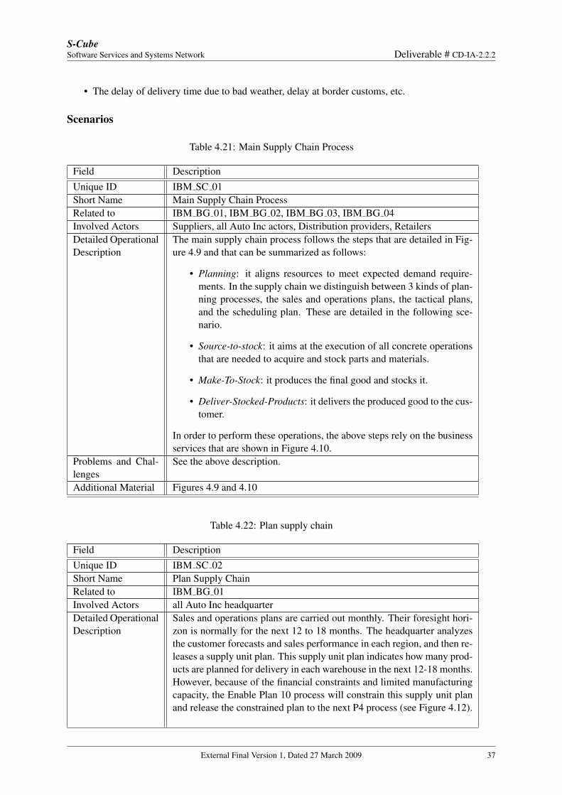
Table 4.21: Main Supply Chain Process
Field DescriptionUnique ID IBM SC 01Short Name Main Supply Chain ProcessRelated to IBM BG 01, IBM BG 02, IBM BG 03, IBM BG 04Involved Actors Suppliers, all Auto Inc actors, Distribution providers, RetailersDetailed OperationalDescription
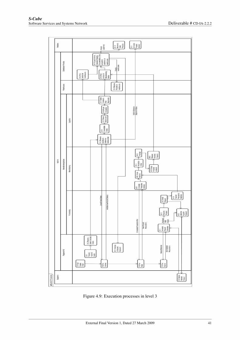
The main supply chain process follows the steps that are detailed in Fig-ure 4.9 and that can be summarized as follows:
• Planning: it aligns resources to meet expected demand require-ments. In the supply chain we distinguish between 3 kinds of plan-ning processes, the sales and operations plans, the tactical plans,and the scheduling plan. These are detailed in the following sce-nario.
• Source-to-stock: it aims at the execution of all concrete operationsthat are needed to acquire and stock parts and materials.
• Make-To-Stock: it produces the final good and stocks it.
• Deliver-Stocked-Products: it delivers the produced good to the cus-tomer.
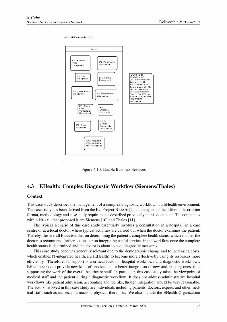
In order to perform these operations, the above steps rely on the businessservices that are shown in Figure 4.10.
Problems and Chal-lenges
See the above description.
Additional Material Figures 4.9 and 4.10
Table 4.22: Plan supply chain
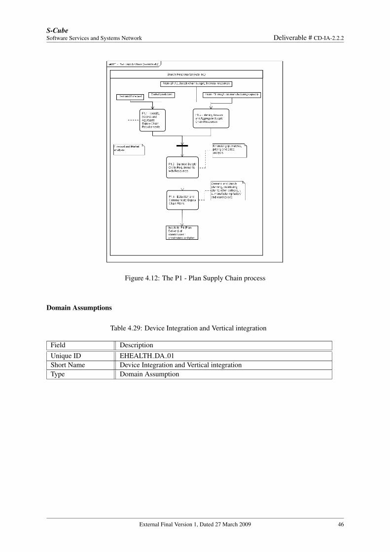
Field DescriptionUnique ID IBM SC 02Short Name Plan Supply ChainRelated to IBM BG 01Involved Actors all Auto Inc headquarterDetailed OperationalDescription
Sales and operations plans are carried out monthly. Their foresight hori-zon is normally for the next 12 to 18 months. The headquarter analyzesthe customer forecasts and sales performance in each region, and then re-leases a supply unit plan. This supply unit plan indicates how many prod-ucts are planned for delivery in each warehouse in the next 12-18 months.However, because of the financial constraints and limited manufacturingcapacity, the Enable Plan 10 process will constrain this supply unit planand release the constrained plan to the next P4 process (see Figure 4.12).
External Final Version 1, Dated 27 March 2009 37
S-CubeSoftware Services and Systems Network Deliverable # CD-IA-2.2.2
Problems and Chal-lenges
None.
Additional Material Figure 4.12
Table 4.23: Tactical planning
Field DescriptionUnique ID IBM SC 03Short Name Tactical planningRelated to IBM BG 01, IBM BG 02, IBM BG 03Involved Actors all Auto Inc headquarterDetailed OperationalDescription
The tactical planning activities comprise Plan Deliver (P4), Plan Manu-facturing (P3), and Plan Source (P2), which foresee the plans for the next12- 14 weeks. Inputs for the P4 process are the constrained unit forecastfrom P1 and the unconfirmed sale orders from each region provided bythe Deliver process D1. The P4 process decides then how many productsshould be delivered from each warehouse and informs the D1 process. Aswe see within the D1 process, the D1.3 step decides to fulfill the priori-tized orders and postpone the other ones to the next round. The result ofplanning delivery in P4 process leads to the new replenishments ordersfor the warehouses, which will be sent to the manufacturing factory.
Problems and Chal-lenges
None.
Additional Material None
Table 4.24: Plan Manufacturing
Field DescriptionUnique ID IBM SC 04Short Name Plan ManufacturingRelated to IBM BG 01, IBM BG 03Involved Actors all Auto Inc headquarterDetailed OperationalDescription
The Plan Make (P3) process takes into account these orders and the al-ready scheduled production plan, and then decides how many productsshould be produced more for the near future. The result of this processis a new production plan that should be scheduled in the M1 process(Make-to-Stock). Last but not least in the planning phase, the P3 processmust compensate the materials it consumed for the previous productions,by means of passing the material requirements to the Plan Source (P2)process. The P2 process considers these material requisitions with the al-ready ordered material amounts, and then decides the volume of materialsthat should be sourced and stocked. The P2 process results in a sched-uled material requisitions that will be fulfilled by the Source-To-Stock(S1) process.
External Final Version 1, Dated 27 March 2009 38
S-CubeSoftware Services and Systems Network Deliverable # CD-IA-2.2.2
Problems and Chal-lenges
None.
Additional Material None
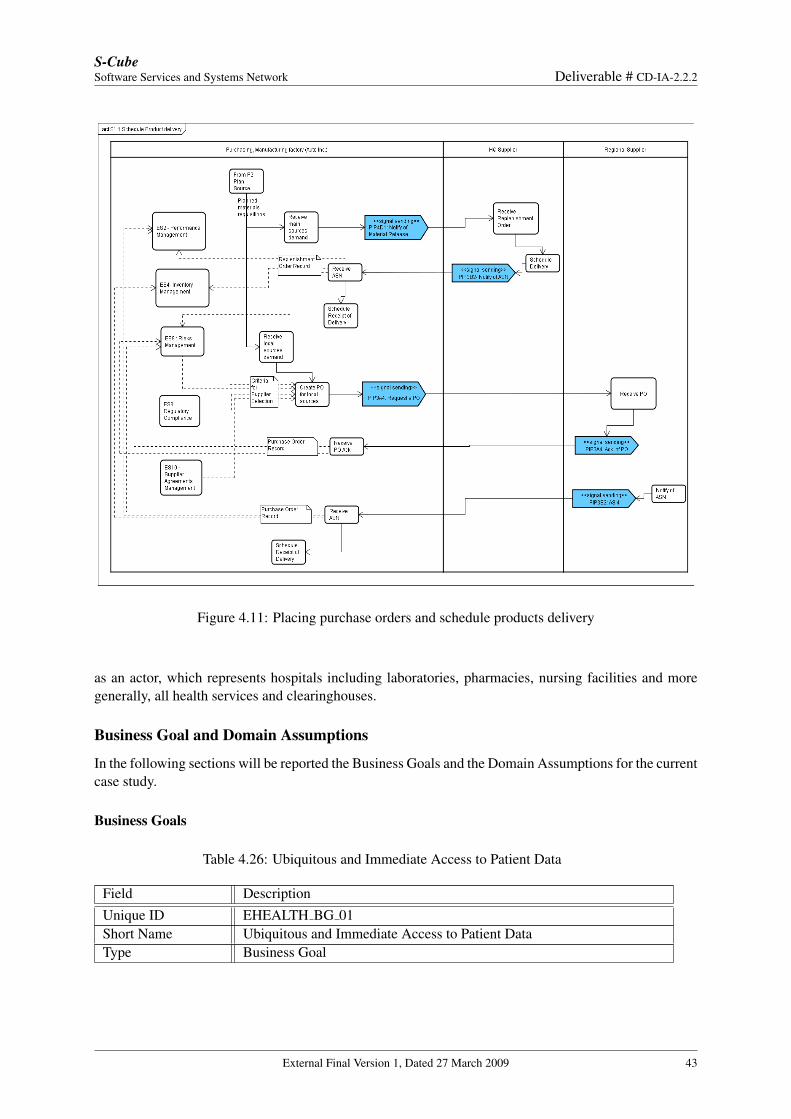
Table 4.25: Schedule product delivery
Field DescriptionUnique ID IBM SC 05Short Name Placing purchase orders and schedule products deliveryRelated to IBM BG 03, IBM BG 04Involved Actors Auto Inc manufactoring factory, Auto Inc EU headquarter, SupplierDetailed OperationalDescription
The process described by this scenario is responsible for selecting suit-able suppliers, purchasing goods, transferring products into materials,and, lastly, stocking materials.As we can see from Figure 4.11, the Auto Inc and its Headquarter supplieroperate in the inventory replenishment strategy. This means that if thereis a demand for main automobile parts, the purchasing department willsend a notification of material release (PIP4D1) to the Headquarter andthen receive an Advanced Notification of Shipment (ASN) (PIP3B2) toschedule the receipt.For other automobile parts and accessories, Auto Inc can place orders atthe regional suppliers. The order placement is defined with the PIP3A4and the acknowledgement should be sent back to Auto Inc with PIP3A4as well. As soon as the products are ready for shipment, the suppliers willsend an ASN (PIP3B2) to the Auto Inc.Figure 4.11 also points out at the role of some external business ser-vices. The interaction with them is needed for data management, perfor-mance measurement, and performance assessment. In particular, recordsof purchase and replenishment orders are used to analyze the statisti-cal performance, or to keep track and detect the risks of the current or-ders. Some typical KPIs such as Order-To-Acknowledgement, Order-To-ASN, etc. are measured with the records. In particular, if the Order-To-Acknowledgement and Order-To-ASN are not received or returned toolate, the process will schedule new material demand and place new sup-ply order in order to ensure the amount of source materials in stock forfuture production. We assume that there is no need to cancel the oldorder in this case. Sources will still be imported excessively. Only thereputation of supplier will be deducted.The business services also provide the information needed to select thebest suppliers to place purchase orders. In Figure 4.11, the selection cri-teria are based on the following elements:
External Final Version 1, Dated 27 March 2009 39
S-CubeSoftware Services and Systems Network Deliverable # CD-IA-2.2.2
• Prices and Availability: which suppliers offer cheaper prices andlarger availability will have more chance for collaborating. TheSuppliers Management subprocess (ES10) maintains informationabout the current product catalogue (including prices and availabil-ity) of all suppliers, and hence can provide an ordered list based onprice and availability.
• Reputation (based on statistical data of previous transactions):the performance, reliability, and quality are also important selec-tion criteria. The Suppliers Management subpreocess (ES10) alsomaintains the statistical information about the suppliers and canprovide a ranking list of the suppliers, based on performance, reli-ability and quality.
• Influences of compliance rules, risks: In case Auto Inc must followsome external and internal compliance rules that some supplierscannot hold, or the suppliers seem to yield too many risks, AutoInc might have to choose other suppliers, even though they couldbe less efficient.
The Risk Management subprocess (ES9) estimates the risk of importinggoods from each supplier and provides also the ranking list of the suppli-ers.
Problems and Chal-lenges
See the detailed operational description.
Additional Material Figure 4.11
External Final Version 1, Dated 27 March 2009 40
S-CubeSoftware Services and Systems Network Deliverable # CD-IA-2.2.2
Figure 4.9: Execution processes in level 3
External Final Version 1, Dated 27 March 2009 41
S-CubeSoftware Services and Systems Network Deliverable # CD-IA-2.2.2
Figure 4.10: Enable Business Services
4.3 EHealth: Complex Diagnostic Workflow (Siemens/Thales)
Context
This case study describes the management of a complex diagnostic workflow in a EHealth environment.The case study has been derived from the EU Project NEXOF [1], and adapted to the different descriptionformat, methodology and case study requirements described previously in this document. The companieswithin NEXOF that proposed it are Siemens [10] and Thales [11].
The typical scenario of this case study essentially involves a consultation in a hospital, in a carecentre or at a local doctor, where typical activities are carried out when the doctor examines the patient.Thereby, the overall focus is either on determining the patient’s complete health status, which enables thedoctor to recommend further actions, or on integrating useful services in the workflow once the completehealth status is determined and the doctor is about to take diagnostic measures.
This case study becomes generally relevant due to the demographic change and to increasing costs,which enables IT-integrated healthcare (EHealth) to become more effective by using its resources moreefficiently. Therefore, IT support is a critical factor in hospital workflows and diagnostic workflows.EHealth seeks to provide new kind of services and a better integration of new and existing ones, thussupporting the work of the overall healthcare staff. In particular, this case study takes the viewpoint ofmedical staff and the patient during a diagnostic workflow. It does not address administrative hospitalworkflows like patient admission, accounting and the like, though integration would be very reasonable.The actors involved in this case study are individuals including patients, doctors, experts and other med-ical staff, such as nurses, pharmacists, physical therapists. We also include the EHealth Organization
External Final Version 1, Dated 27 March 2009 42
S-CubeSoftware Services and Systems Network Deliverable # CD-IA-2.2.2
Figure 4.11: Placing purchase orders and schedule products delivery
as an actor, which represents hospitals including laboratories, pharmacies, nursing facilities and moregenerally, all health services and clearinghouses.
Business Goal and Domain Assumptions
In the following sections will be reported the Business Goals and the Domain Assumptions for the currentcase study.
Business Goals
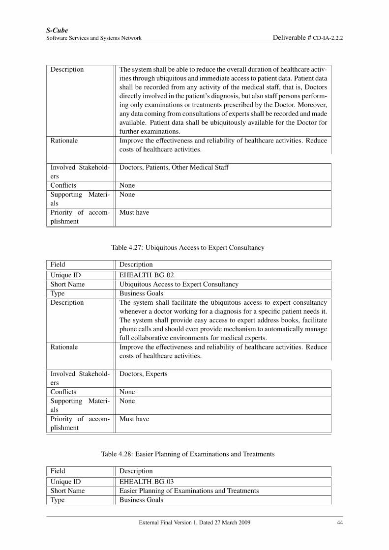
Table 4.26: Ubiquitous and Immediate Access to Patient Data
Field DescriptionUnique ID EHEALTH BG 01Short Name Ubiquitous and Immediate Access to Patient DataType Business Goal
External Final Version 1, Dated 27 March 2009 43
S-CubeSoftware Services and Systems Network Deliverable # CD-IA-2.2.2
Description The system shall be able to reduce the overall duration of healthcare activ-ities through ubiquitous and immediate access to patient data. Patient datashall be recorded from any activity of the medical staff, that is, Doctorsdirectly involved in the patient’s diagnosis, but also staff persons perform-ing only examinations or treatments prescribed by the Doctor. Moreover,any data coming from consultations of experts shall be recorded and madeavailable. Patient data shall be ubiquitously available for the Doctor forfurther examinations.
Rationale Improve the effectiveness and reliability of healthcare activities. Reducecosts of healthcare activities.
Involved Stakehold-ers
Doctors, Patients, Other Medical Staff
Conflicts NoneSupporting Materi-als
None
Priority of accom-plishment
Must have
Table 4.27: Ubiquitous Access to Expert Consultancy
Field DescriptionUnique ID EHEALTH BG 02Short Name Ubiquitous Access to Expert ConsultancyType Business GoalsDescription The system shall facilitate the ubiquitous access to expert consultancy
whenever a doctor working for a diagnosis for a specific patient needs it.The system shall provide easy access to expert address books, facilitatephone calls and should even provide mechanism to automatically managefull collaborative environments for medical experts.
Rationale Improve the effectiveness and reliability of healthcare activities. Reducecosts of healthcare activities.
Involved Stakehold-ers
Doctors, Experts
Conflicts NoneSupporting Materi-als
None
Priority of accom-plishment
Must have
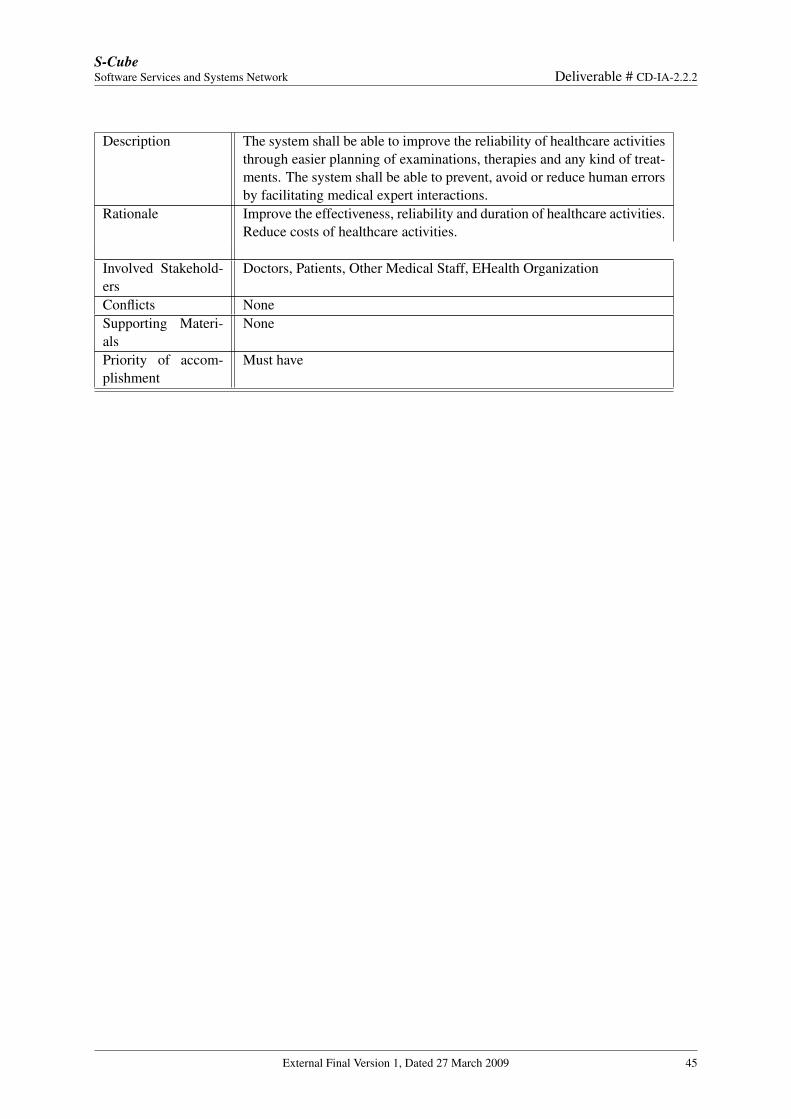
Table 4.28: Easier Planning of Examinations and Treatments
Field DescriptionUnique ID EHEALTH BG 03Short Name Easier Planning of Examinations and TreatmentsType Business Goals
External Final Version 1, Dated 27 March 2009 44
S-CubeSoftware Services and Systems Network Deliverable # CD-IA-2.2.2
Description The system shall be able to improve the reliability of healthcare activitiesthrough easier planning of examinations, therapies and any kind of treat-ments. The system shall be able to prevent, avoid or reduce human errorsby facilitating medical expert interactions.
Rationale Improve the effectiveness, reliability and duration of healthcare activities.Reduce costs of healthcare activities.
Involved Stakehold-ers
Doctors, Patients, Other Medical Staff, EHealth Organization
Conflicts NoneSupporting Materi-als
None
Priority of accom-plishment
Must have
External Final Version 1, Dated 27 March 2009 45
S-CubeSoftware Services and Systems Network Deliverable # CD-IA-2.2.2
Figure 4.12: The P1 - Plan Supply Chain process
Domain Assumptions
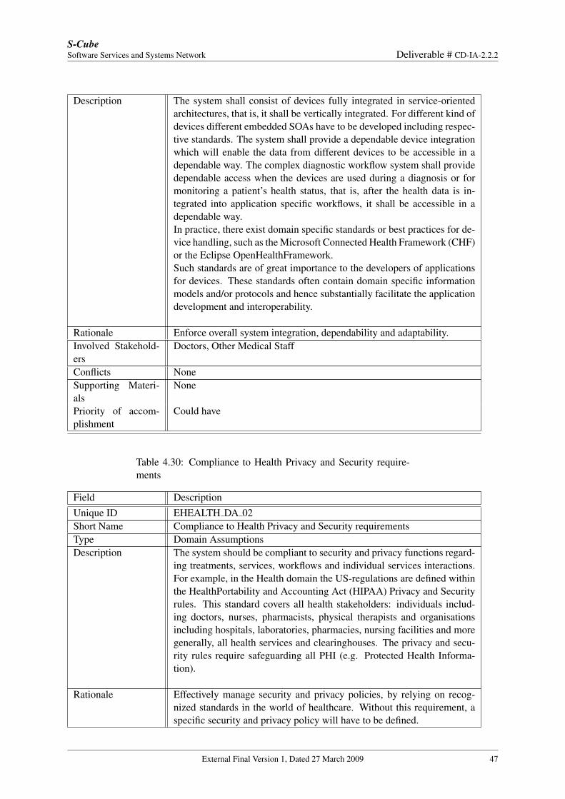
Table 4.29: Device Integration and Vertical integration
Field DescriptionUnique ID EHEALTH DA 01Short Name Device Integration and Vertical integrationType Domain Assumption
External Final Version 1, Dated 27 March 2009 46
S-CubeSoftware Services and Systems Network Deliverable # CD-IA-2.2.2
Description The system shall consist of devices fully integrated in service-orientedarchitectures, that is, it shall be vertically integrated. For different kind ofdevices different embedded SOAs have to be developed including respec-tive standards. The system shall provide a dependable device integrationwhich will enable the data from different devices to be accessible in adependable way. The complex diagnostic workflow system shall providedependable access when the devices are used during a diagnosis or formonitoring a patient’s health status, that is, after the health data is in-tegrated into application specific workflows, it shall be accessible in adependable way.In practice, there exist domain specific standards or best practices for de-vice handling, such as the Microsoft Connected Health Framework (CHF)or the Eclipse OpenHealthFramework.Such standards are of great importance to the developers of applicationsfor devices. These standards often contain domain specific informationmodels and/or protocols and hence substantially facilitate the applicationdevelopment and interoperability.
Rationale Enforce overall system integration, dependability and adaptability.Involved Stakehold-ers
Doctors, Other Medical Staff
Conflicts NoneSupporting Materi-als
None
Priority of accom-plishment
Could have
Table 4.30: Compliance to Health Privacy and Security require-ments
Field DescriptionUnique ID EHEALTH DA 02Short Name Compliance to Health Privacy and Security requirementsType Domain AssumptionsDescription The system should be compliant to security and privacy functions regard-
ing treatments, services, workflows and individual services interactions.For example, in the Health domain the US-regulations are defined withinthe HealthPortability and Accounting Act (HIPAA) Privacy and Securityrules. This standard covers all health stakeholders: individuals includ-ing doctors, nurses, pharmacists, physical therapists and organisationsincluding hospitals, laboratories, pharmacies, nursing facilities and moregenerally, all health services and clearinghouses. The privacy and secu-rity rules require safeguarding all PHI (e.g. Protected Health Informa-tion).
Rationale Effectively manage security and privacy policies, by relying on recog-nized standards in the world of healthcare. Without this requirement, aspecific security and privacy policy will have to be defined.
External Final Version 1, Dated 27 March 2009 47
S-CubeSoftware Services and Systems Network Deliverable # CD-IA-2.2.2
Involved Stakehold-ers
Doctors, Patients, Other Medical Staff, EHealth Organization
Supporting Materi-als
Some documents that illustrate and explain this requirement:
• http://www.hipaa.org/• http://www.hhs.gov/ocr/hipaa/finalreg.html• http://privacyruleandresearch.nih.gov/resources.asp• http://www.hipaacomply.com/• http://www.ioma.org/pdf/iomahipaahelp.pdf
Conflicts NonePriority of accom-plishment
Should have
External Final Version 1, Dated 27 March 2009 48
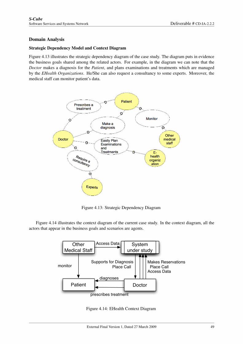
S-CubeSoftware Services and Systems Network Deliverable # CD-IA-2.2.2
Domain Analysis
Strategic Dependency Model and Context Diagram
Figure 4.13 illustrates the strategic dependency diagram of the case study. The diagram puts in evidencethe business goals shared among the related actors. For example, in the diagram we can note that theDoctor makes a diagnosis for the Patient, and plans examinations and treatments which are managedby the EHealth Organizations. He/She can also request a consultancy to some experts. Moreover, themedical staff can monitor patient’s data.
Figure 4.13: Strategic Dependency Diagram
Figure 4.14 illustrates the context diagram of the current case study. In the context diagram, all theactors that appear in the business goals and scenarios are agents.
System under study
Doctor
Other Medical Staff
Access Data
Access Data
Makes ReservationsPlace Call
Supports for DiagnosisPlace Call
Patient
monitor
diagnoses
prescribes treatment
Figure 4.14: EHealth Context Diagram
External Final Version 1, Dated 27 March 2009 49
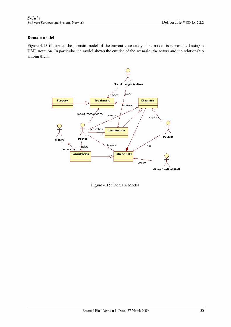
S-CubeSoftware Services and Systems Network Deliverable # CD-IA-2.2.2
Domain model
Figure 4.15 illustrates the domain model of the current case study. The model is represented using aUML notation. In particular the model shows the entities of the scenario, the actors and the relationshipamong them.
Figure 4.15: Domain Model
External Final Version 1, Dated 27 March 2009 50
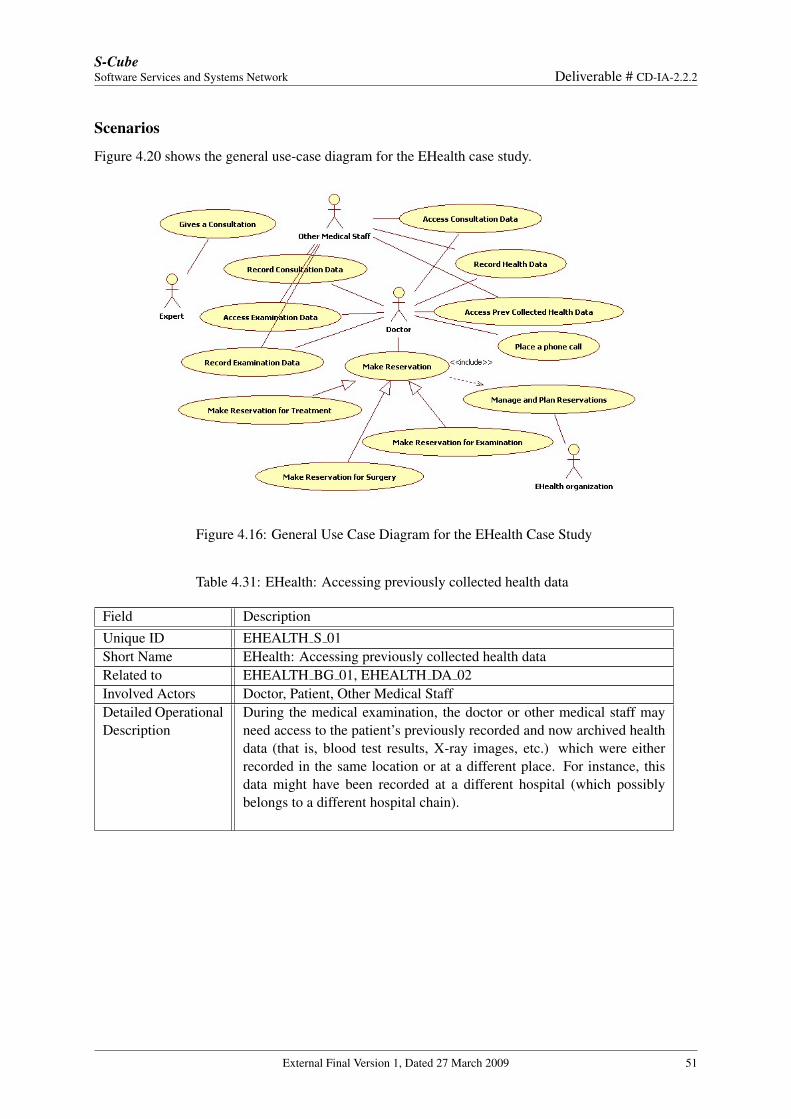
S-CubeSoftware Services and Systems Network Deliverable # CD-IA-2.2.2
Scenarios
Figure 4.20 shows the general use-case diagram for the EHealth case study.
Figure 4.16: General Use Case Diagram for the EHealth Case Study
Table 4.31: EHealth: Accessing previously collected health data
Field DescriptionUnique ID EHEALTH S 01Short Name EHealth: Accessing previously collected health dataRelated to EHEALTH BG 01, EHEALTH DA 02Involved Actors Doctor, Patient, Other Medical StaffDetailed OperationalDescription
During the medical examination, the doctor or other medical staff mayneed access to the patient’s previously recorded and now archived healthdata (that is, blood test results, X-ray images, etc.) which were eitherrecorded in the same location or at a different place. For instance, thisdata might have been recorded at a different hospital (which possiblybelongs to a different hospital chain).
External Final Version 1, Dated 27 March 2009 51
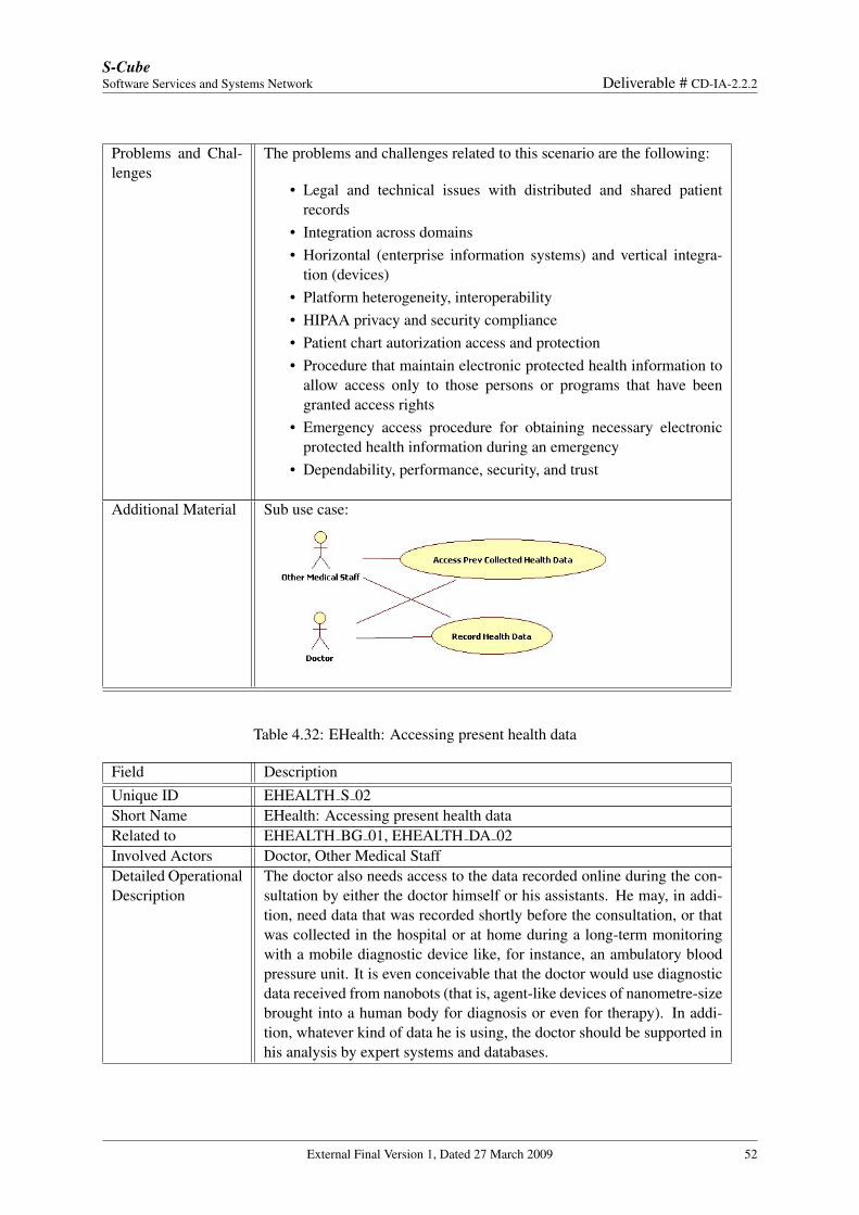
S-CubeSoftware Services and Systems Network Deliverable # CD-IA-2.2.2
Problems and Chal-lenges
The problems and challenges related to this scenario are the following:
• Legal and technical issues with distributed and shared patientrecords
• Integration across domains• Horizontal (enterprise information systems) and vertical integra-
tion (devices)• Platform heterogeneity, interoperability• HIPAA privacy and security compliance• Patient chart autorization access and protection• Procedure that maintain electronic protected health information to
allow access only to those persons or programs that have beengranted access rights
• Emergency access procedure for obtaining necessary electronicprotected health information during an emergency
• Dependability, performance, security, and trust
Additional Material Sub use case:
Table 4.32: EHealth: Accessing present health data
Field DescriptionUnique ID EHEALTH S 02Short Name EHealth: Accessing present health dataRelated to EHEALTH BG 01, EHEALTH DA 02Involved Actors Doctor, Other Medical StaffDetailed OperationalDescription
The doctor also needs access to the data recorded online during the con-sultation by either the doctor himself or his assistants. He may, in addi-tion, need data that was recorded shortly before the consultation, or thatwas collected in the hospital or at home during a long-term monitoringwith a mobile diagnostic device like, for instance, an ambulatory bloodpressure unit. It is even conceivable that the doctor would use diagnosticdata received from nanobots (that is, agent-like devices of nanometre-sizebrought into a human body for diagnosis or even for therapy). In addi-tion, whatever kind of data he is using, the doctor should be supported inhis analysis by expert systems and databases.
External Final Version 1, Dated 27 March 2009 52
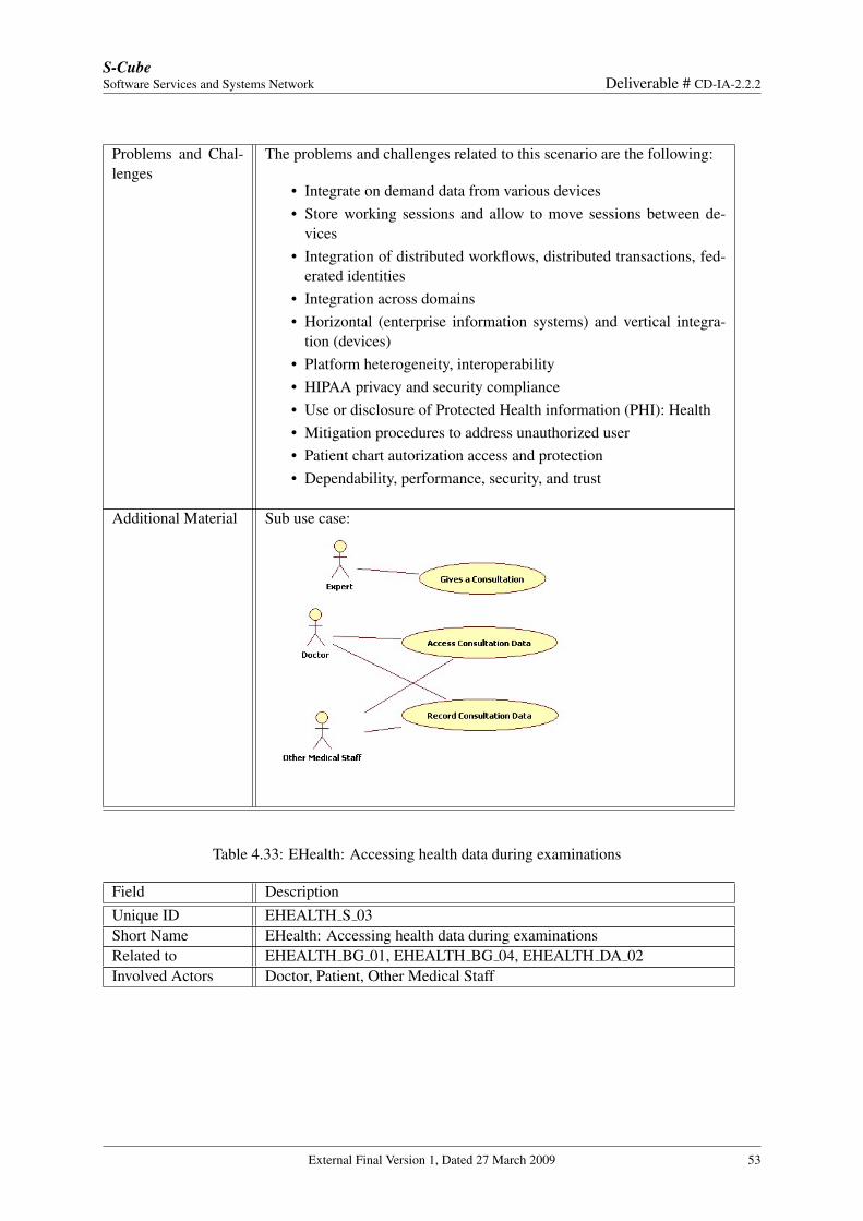
S-CubeSoftware Services and Systems Network Deliverable # CD-IA-2.2.2
Problems and Chal-lenges
The problems and challenges related to this scenario are the following:
• Integrate on demand data from various devices• Store working sessions and allow to move sessions between de-
vices• Integration of distributed workflows, distributed transactions, fed-
erated identities• Integration across domains• Horizontal (enterprise information systems) and vertical integra-
tion (devices)• Platform heterogeneity, interoperability• HIPAA privacy and security compliance• Use or disclosure of Protected Health information (PHI): Health• Mitigation procedures to address unauthorized user• Patient chart autorization access and protection• Dependability, performance, security, and trust
Additional Material Sub use case:
Table 4.33: EHealth: Accessing health data during examinations
Field DescriptionUnique ID EHEALTH S 03Short Name EHealth: Accessing health data during examinationsRelated to EHEALTH BG 01, EHEALTH BG 04, EHEALTH DA 02Involved Actors Doctor, Patient, Other Medical Staff
External Final Version 1, Dated 27 March 2009 53
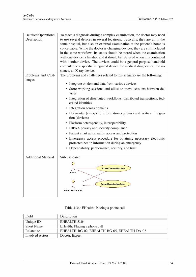
S-CubeSoftware Services and Systems Network Deliverable # CD-IA-2.2.2
Detailed OperationalDescription
To reach a diagnosis during a complex examination, the doctor may needto use several devices in several locations. Typically, they are all in thesame hospital, but also an external examination at the patient’s home isconceivable. While the doctor is changing devices, they are still includedin the same workflow. Its status should be stored when the examinationwith one device is finished and it should be retrieved when it is continuedwith another device. The devices could be a general-purpose handheldcomputer or a specific integrated device for medical diagnostics, for in-stance, an X-ray device.
Problems and Chal-lenges
The problems and challenges related to this scenario are the following:
• Integrate on demand data from various devices• Store working sessions and allow to move sessions between de-
vices• Integration of distributed workflows, distributed transactions, fed-
erated identities• Integration across domains• Horizontal (enterprise information systems) and vertical integra-
tion (devices)• Platform heterogeneity, interoperability• HIPAA privacy and security compliance• Patient chart autorization access and protection• Emergency access procedure for obtaining necessary electronic
protected health information during an emergency• Dependability, performance, security, and trust
Additional Material Sub use-case:
Table 4.34: EHealth: Placing a phone call
Field DescriptionUnique ID EHEALTH S 04Short Name EHealth: Placing a phone callRelated to EHEALTH BG 02, EHEALTH BG 05, EHEALTH DA 02Involved Actors Doctor, Expert
External Final Version 1, Dated 27 March 2009 54
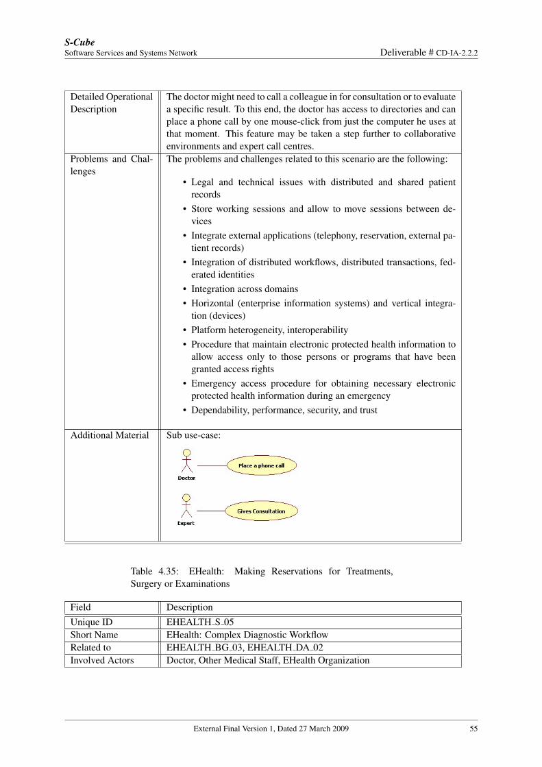
S-CubeSoftware Services and Systems Network Deliverable # CD-IA-2.2.2
Detailed OperationalDescription
The doctor might need to call a colleague in for consultation or to evaluatea specific result. To this end, the doctor has access to directories and canplace a phone call by one mouse-click from just the computer he uses atthat moment. This feature may be taken a step further to collaborativeenvironments and expert call centres.
Problems and Chal-lenges
The problems and challenges related to this scenario are the following:
• Legal and technical issues with distributed and shared patientrecords
• Store working sessions and allow to move sessions between de-vices
• Integrate external applications (telephony, reservation, external pa-tient records)
• Integration of distributed workflows, distributed transactions, fed-erated identities
• Integration across domains• Horizontal (enterprise information systems) and vertical integra-
tion (devices)• Platform heterogeneity, interoperability• Procedure that maintain electronic protected health information to
allow access only to those persons or programs that have beengranted access rights
• Emergency access procedure for obtaining necessary electronicprotected health information during an emergency
• Dependability, performance, security, and trust
Additional Material Sub use-case:
Table 4.35: EHealth: Making Reservations for Treatments,Surgery or Examinations
Field DescriptionUnique ID EHEALTH S 05Short Name EHealth: Complex Diagnostic WorkflowRelated to EHEALTH BG 03, EHEALTH DA 02Involved Actors Doctor, Other Medical Staff, EHealth Organization
External Final Version 1, Dated 27 March 2009 55
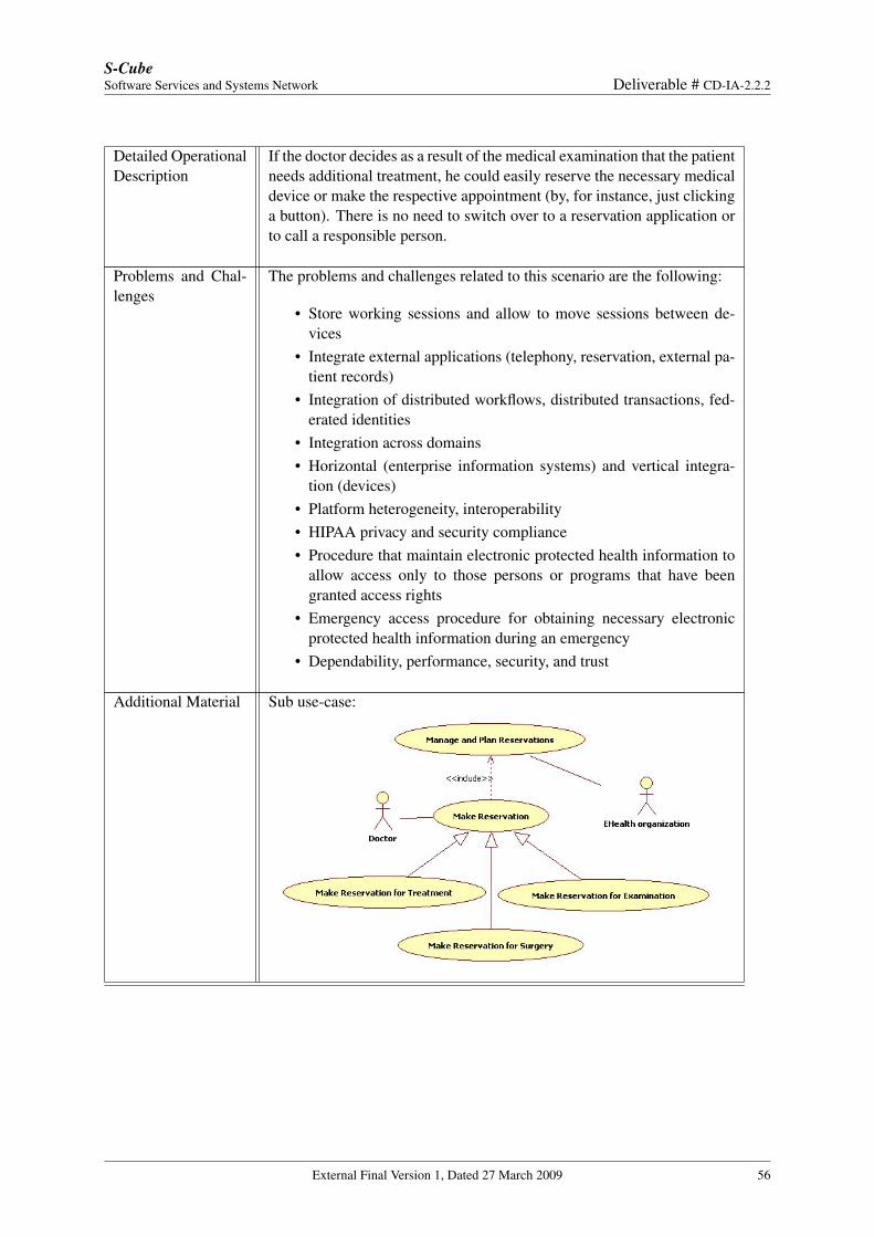
S-CubeSoftware Services and Systems Network Deliverable # CD-IA-2.2.2
Detailed OperationalDescription
If the doctor decides as a result of the medical examination that the patientneeds additional treatment, he could easily reserve the necessary medicaldevice or make the respective appointment (by, for instance, just clickinga button). There is no need to switch over to a reservation application orto call a responsible person.
Problems and Chal-lenges
The problems and challenges related to this scenario are the following:
• Store working sessions and allow to move sessions between de-vices
• Integrate external applications (telephony, reservation, external pa-tient records)
• Integration of distributed workflows, distributed transactions, fed-erated identities
• Integration across domains• Horizontal (enterprise information systems) and vertical integra-
tion (devices)• Platform heterogeneity, interoperability• HIPAA privacy and security compliance• Procedure that maintain electronic protected health information to
allow access only to those persons or programs that have beengranted access rights
• Emergency access procedure for obtaining necessary electronicprotected health information during an emergency
• Dependability, performance, security, and trust
Additional Material Sub use-case:
External Final Version 1, Dated 27 March 2009 56
S-CubeSoftware Services and Systems Network Deliverable # CD-IA-2.2.2
4.4 Traffic Management: Large Scale Emergency Handling (Siemens)
Context
This case study describes a traffic management system which is designed to manage normal situationsas well as handle emergency cases. Such emergency case handling includes several different actions,such as the direction of rescue forces to the location of the accident as well as the management of trafficdeviations. The actors involved in this case study are traffic managers, that is, the individuals accountablefor entities controlling the traffic management system in a particular geographical area, generic rescueforces (e.g., police and ambulances), and citizens, such as motorists and pedestrians. The case studyhas been derived from the EU Project NEXOF [1], and adapted to the different description format andmethodology described previously in this deliverable. The company within NEXOF that proposed it isSiemens [10].
Business Goal and Domain Assumptions
In the following sections will be reported the Business Goals and the Domain Assumptions for the currentcase study.
Business Goals
Table 4.36: Management of Normal Traffic Conditions
Field DescriptionUnique ID TRAFFIC BG 01Short Name Management of Normal Traffic ConditionsType Business GoalDescription The system shall regulate normal traffic conditions in order to optimize
some parameters such as total noise, overall throughput, and air pollu-tion. The system shall consider different perspectives with respect to hisgeographical zone of competence and the corresponding administrativepowers of its owner entity. In particular, the system shalll consider differ-ent needs, such as the ones of pedestrians and motorists, and other factorslike public events, school and working hours, holidays or public regu-lations which may alter traffic demand and needs during conditions thatdoes not involve emergencies.
Rationale Optimize traffic quality parameters and integrate stakeholders needs.Involved Stakehold-ers
Traffic Managers, Citizens
Priority of accom-plishment
Must have
Table 4.37: Management of Critical Traffic Conditions
Field DescriptionUnique ID TRAFFIC BG 02Short Name Management of Critical Conditions in TrafficType Business Goal
External Final Version 1, Dated 27 March 2009 57
S-CubeSoftware Services and Systems Network Deliverable # CD-IA-2.2.2
Description The system shall react on different changed conditions in the traffic situ-ation. For instance, the system shall properly react and be able to man-age the case of traffic accidents and emergencies, as well as major roadconstructions or similar activities. In those situations, the system shallexecute new control and management strategies. The traffic managementsystem should then be able to identify the key necessities of the new sit-uation, and then it shall retrieve an appropriate realization of the neededcontrol mechanisms and adapt to the new strategies. The system shallalso be designed such that it should be able to manage also unforeseensituations such as the ones determined by terrorist attacks. The therebyrequired reaction pattern of the system is not specific to the traffic man-agement domain, but inherent to (at least partly) autonomously reactingsystems.In case of a generic emergency, the traffic management system shall reactquickly and change its strategies. This includes the reasonably fast selec-tion of the right new strategy as well as the swift propagation of the newrules to the traffic control devices. This includes for example the rapidreconfiguration of traffic lights.Reconfiguration and adaptation process shall be performed by the systemin a very short time in the case of emergency. Moreover, the system shallimplement a reconfiguration and adaptation control process which hasto come to a conclusive decision in a very short time and, in particular,does not fall into an “adaptation livelock”, that is, that is does not try toperform again and again repeated adaptation steps without coming to areasonable and stable new control structure in the requested time.
Rationale Need to react autonomously on unexpected and unforeseen situations ina reasonable way.
Involved Stakehold-ers
Traffic Managers, Rescue forces, Citizens
Priority of accom-plishment
Must have
Table 4.38: Integrity
Field DescriptionUnique ID TRAFFIC BG 03Short Name IntegrityType Business GoalDescription The system shall detect any attempt to jeopardize the traffic management
system, that is, to override the decisions of the traffic management systemfrom outside the system itself. The system shall also block any of thoseattempts or successfully self-repair itself. Examples of those attemptsconsist of manipulations of the sensors and the control devices, or theintroduction of harmful strategies.
External Final Version 1, Dated 27 March 2009 58
S-CubeSoftware Services and Systems Network Deliverable # CD-IA-2.2.2
Rationale Minimize the risk of manipulations of the traffic management system ina wrongful manner, which may result in a disastrous traffic situation withall its bad consequences, expecially in an emergency scenario.
Involved Stakehold-ers
Traffic Managers
Priority of accom-plishment
Must have
Table 4.39: Traffic Management Systems Coordination
Field DescriptionUnique ID TRAFFIC BG 04Short Name Traffic Management Systems CoordinationType Business GoalDescription It is reasonable to expect that different traffic management systems are
operating in different local areas (e.g., different cities) or managing traf-fic at different geographical dimensions (e.g., cities versus regions). Eachof these has a correpsonding responsible government body, and a corre-sponding responsible individual. Coordination between these systems isneeded because several of them generally deal with different strategies ac-cordng to their geographical dimension and location, and according to thespecific resposibilities and powers as defined by the responsible adminis-trative entity. Those system shall be able to interact both during normalmanagement as well as in the case of emergencies which involve morethan a traffic system and their shared locations. This includes highwaysor roads connecting different cities. Coordination becomes critical whendecisions must be taken at greater geographical levels. In those cases,each traffic management systems shall be able to integrate his processwith the others involved in order to avoid inconsistent or contradictorydecisions.
Rationale Minimize the risk of contradictory decisions when traffic managementsystems have to interact.
Involved Stakehold-ers
Traffic Managers, Rescue forces
Priority of accom-plishment
Must have
Domain Assumptions
Table 4.40: Assumption TRAFFIC DA 01
Field DescriptionUnique ID TRAFFIC DA 01Short Name Heterogeinity and Redundancy of Devices in Traffic Management Sys-
temsType Domain assumption
External Final Version 1, Dated 27 March 2009 59
S-CubeSoftware Services and Systems Network Deliverable # CD-IA-2.2.2
Description Every traffic management system may access distributed devices provid-ing input on different interesting data sources, such as traffic density, carspeed, air pollution, traffic light status, congestion indicators, etc. Thedevices used in the various traffic systems are rather heterogeneus andredundant, that is, they may perform the same or similar functions withdifferent technologies.
Rationale Independence and the lacking co-operation of the political institutionsinvolved in the acquisition and maintenance of the respective traffic man-agement systems, which results in heterogeinity and redundancy of de-vices.
Involved Stakehold-ers
Traffic Managers
Conflicts NoneSupporting Materi-als
None
Priority of accom-plishment
Must have
External Final Version 1, Dated 27 March 2009 60
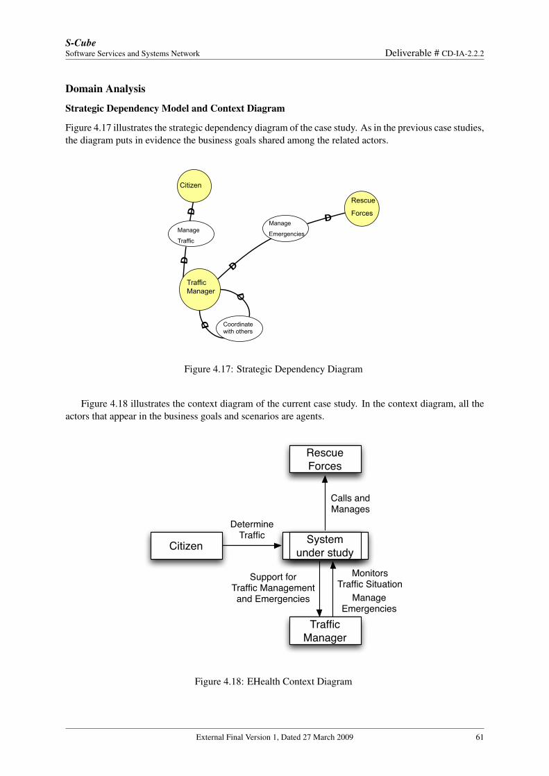
S-CubeSoftware Services and Systems Network Deliverable # CD-IA-2.2.2
Domain Analysis
Strategic Dependency Model and Context Diagram
Figure 4.17 illustrates the strategic dependency diagram of the case study. As in the previous case studies,the diagram puts in evidence the business goals shared among the related actors.
Citizen
Traffic
Manager
Rescue
Forces
Manage
Traffic
Coordinate with others
Manage
Emergencies
Figure 4.17: Strategic Dependency Diagram
Figure 4.18 illustrates the context diagram of the current case study. In the context diagram, all theactors that appear in the business goals and scenarios are agents.
System under study
Traffic Manager
Citizen
DetermineTraffic
Monitors Traffic Situation
Support for Traffic Managementand Emergencies
Rescue Forces
Calls and Manages
ManageEmergencies
Figure 4.18: EHealth Context Diagram
External Final Version 1, Dated 27 March 2009 61
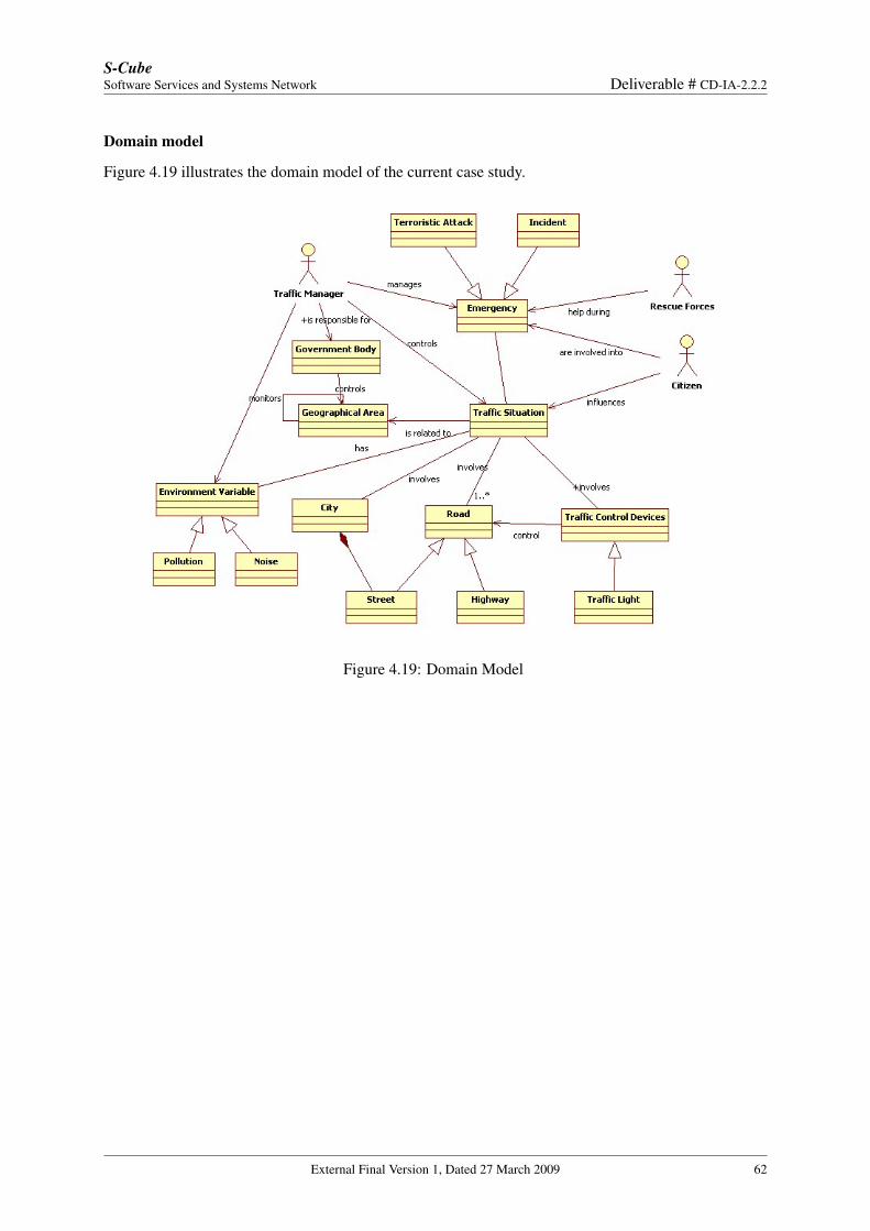
S-CubeSoftware Services and Systems Network Deliverable # CD-IA-2.2.2
Domain model
Figure 4.19 illustrates the domain model of the current case study.
Figure 4.19: Domain Model
External Final Version 1, Dated 27 March 2009 62
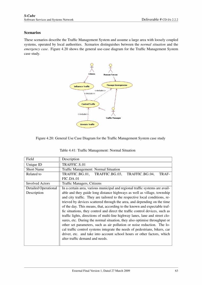
S-CubeSoftware Services and Systems Network Deliverable # CD-IA-2.2.2
Scenarios
These scenarios describe the Traffic Management System and assume a large area with loosely coupledsystems, operated by local authorities. Scenarios distinguishes between the normal situation and theemergency case. Figure 4.20 shows the general use-case diagram for the Traffic Management Systemcase study.
Figure 4.20: General Use Case Diagram for the Traffic Management System case study
Table 4.41: Traffic Management: Normal Situation
Field DescriptionUnique ID TRAFFIC S 01Short Name Traffic Management: Normal SituationRelated to TRAFFIC BG 01, TRAFFIC BG 03, TRAFFIC BG 04, TRAF-
FIC DA 01Involved Actors Traffic Managers, CitizensDetailed OperationalDescription
In a certain area, various municipal and regional traffic systems are avail-able and they guide long distance highways as well as village, townshipand city traffic. They are tailored to the respective local conditions, re-trieved by devices scattered through the area, and depending on the timeof the day. This means, that, according to the known and expectable traf-fic situations, they control and direct the traffic control devices, such astraffic lights, directions of multi-line highway lanes, lane and street clo-sures, etc. During the normal situation, they also optimise throughput orother set parameters, such as air pollution or noise reduction. The lo-cal traffic control systems integrate the needs of pedestrians, bikers, cardriver, etc. and take into account school hours or other factors, whichalter traffic demand and needs.
External Final Version 1, Dated 27 March 2009 63
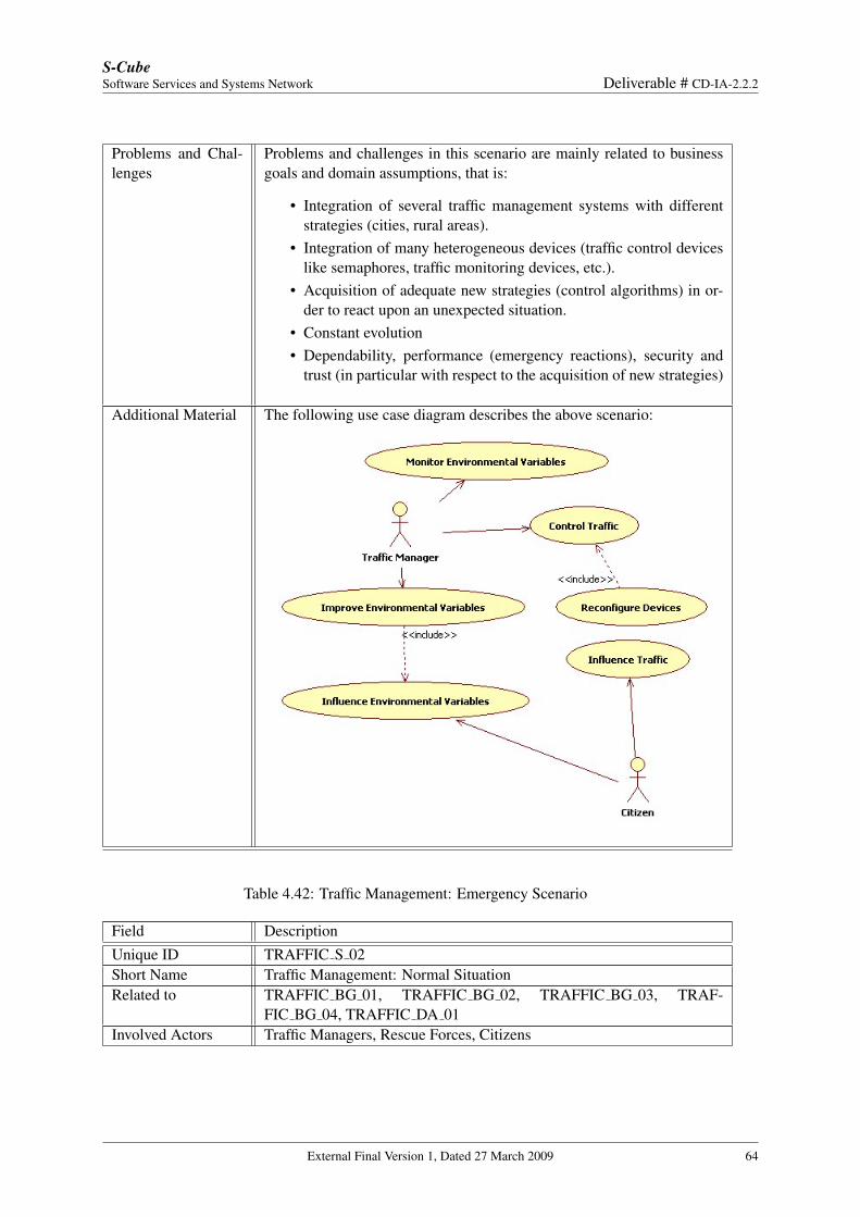
S-CubeSoftware Services and Systems Network Deliverable # CD-IA-2.2.2
Problems and Chal-lenges
Problems and challenges in this scenario are mainly related to businessgoals and domain assumptions, that is:
• Integration of several traffic management systems with differentstrategies (cities, rural areas).
• Integration of many heterogeneous devices (traffic control deviceslike semaphores, traffic monitoring devices, etc.).
• Acquisition of adequate new strategies (control algorithms) in or-der to react upon an unexpected situation.
• Constant evolution• Dependability, performance (emergency reactions), security and
trust (in particular with respect to the acquisition of new strategies)
Additional Material The following use case diagram describes the above scenario:
Table 4.42: Traffic Management: Emergency Scenario
Field DescriptionUnique ID TRAFFIC S 02Short Name Traffic Management: Normal SituationRelated to TRAFFIC BG 01, TRAFFIC BG 02, TRAFFIC BG 03, TRAF-
FIC BG 04, TRAFFIC DA 01Involved Actors Traffic Managers, Rescue Forces, Citizens
External Final Version 1, Dated 27 March 2009 64
S-CubeSoftware Services and Systems Network Deliverable # CD-IA-2.2.2
Detailed OperationalDescription
This scenario deals with the management of a critical and possible unex-pected situation or emergency. An example of such a situation is a seriousaccident, where several actions must be performed.Typical actions to be performed during emergency are:
• closing or limiting the traffic to / from the involved location (suchas an highway);
• rescue forces have to be directed to the location of the accident andtheir arrival has to be facilitated;
• the traffic has to be deviated through places not intended for heavytraffic;
• traffic management devices reconfiguration (e.g., traffic lights).
Consequently, conflicting and unforeseen situations will occur. The con-trol has to be reconfigured according to unplanned control patterns. Thoseunplanned patterns may have been already used at other locations, andthus they might be offered for re-use.Those available or retrievable control patterns have to be adapted to op-timise the local situation, taking into account the changed conditions andthe still remaining local settings. For example, a local theatre, for in-stance, could still close at the announced time notwithstanding the emer-gency situation. Deviation roads have to be selected accordingly. Sig-nalling patterns, such as traffic light phases, have to be adapted in orderto reduce stop & go traffic, that should also help to kept air pollution low,even if it’s not critical during emergency situations. Decisions have tobe integrated in order to keep “feature interactions” with undesirable re-sults at bay. Those situations are, by definitions, those that are strictlygoal directed and effective itself, but may result in a disaster if appliedtogether.
Problems and Chal-lenges
Problems and challenges in this scenario are mainly related to businessgoals and assumptions, that is:
• Integration of several traffic management systems with differentstrategies (cities, rural areas).
• Integration of many heterogeneous devices (traffic control deviceslike semaphores, traffic monitoring devices, etc.).
• Acquisition of adequate new strategies (control algorithms) in or-der to react upon an unexpected situation.
• Constant evolution• Dependability, performance (emergency reactions), security and
trust (in particular with respect to the acquisition of new strategies)
External Final Version 1, Dated 27 March 2009 65
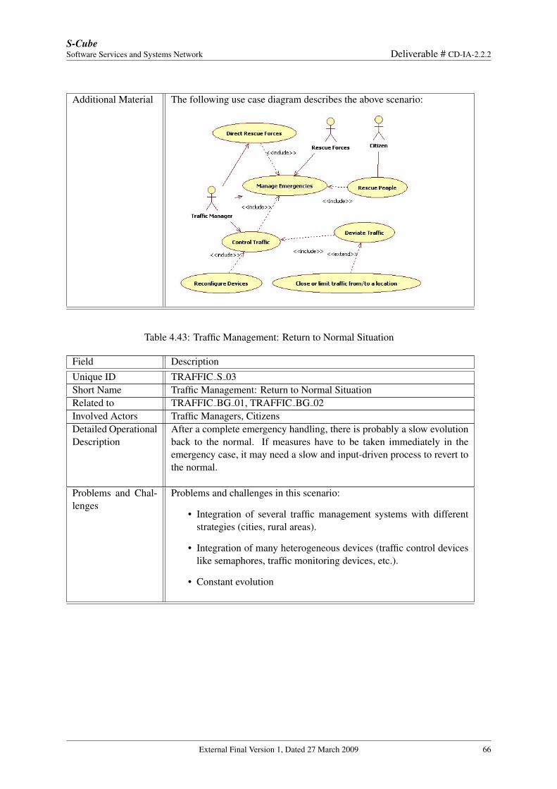
S-CubeSoftware Services and Systems Network Deliverable # CD-IA-2.2.2
Additional Material The following use case diagram describes the above scenario:
Table 4.43: Traffic Management: Return to Normal Situation
Field DescriptionUnique ID TRAFFIC S 03Short Name Traffic Management: Return to Normal SituationRelated to TRAFFIC BG 01, TRAFFIC BG 02Involved Actors Traffic Managers, CitizensDetailed OperationalDescription
After a complete emergency handling, there is probably a slow evolutionback to the normal. If measures have to be taken immediately in theemergency case, it may need a slow and input-driven process to revert tothe normal.
Problems and Chal-lenges
Problems and challenges in this scenario:
• Integration of several traffic management systems with differentstrategies (cities, rural areas).
• Integration of many heterogeneous devices (traffic control deviceslike semaphores, traffic monitoring devices, etc.).
• Constant evolution
External Final Version 1, Dated 27 March 2009 66
S-CubeSoftware Services and Systems Network Deliverable # CD-IA-2.2.2
4.5 E-Government (TIS/Engineering)
Context
Usually when a citizen needs some document from the public sector, he has to go to the appropriatedepartment; often the time spent in queues, and the time spent to reach the right office is very long.E-Government is the process to make information technologies available to the government services inorder to improve the relationships between citizens and their governments (public sector could be madeopen and transparent to the citizens). One of the services made available to the user, is the possibility tosubmit applications to require some service, and receive replies online. At any time during the day, fromtheir locations citizens can access to the offered services and obtain all the needed information withoutspending any time in queues. In such a way, e-government is able to improve the efficiency of publicsector, avoiding the time spent to reach different offices or waiting in queue, resulting in an improvementof the offered services and a better accessibility and transparency of the public services. Not only citizensmay be the the users of the government application, but we can image that all the government agenciesof a city could share data about the citizens and have the need to access to the services of the application,in order to make available, at any time, all the needed information. The case study is derived from theEU project NEXOF [1]. In particular, it has been proposed by Engineering Ingegneria Informatica [12]and TIS [13]. We have mapped it into the format proposed for S-Cube, retrieving the business goals andthe scenarios needed for our description.
Business Goal and Domain Assumptions
In the following sections will be reported the Business Goals and the Domain Assumptions for the currentcase study.
Business Goals
Table 4.44: Statewide provision of online services
Field DescriptionUnique ID TIS BG 1Short Name Statewide provision of online services for citizens, companies, govern-
ment agenciesType Business GoalDescription The infrastructure must be able to make services of the public sector
available to all the users, such as citizens, companies or government agen-cies. Each user can access, from somewhere, to the services providinglogin information; after the login the user can have the possibility to for-ward requests of some documents or require any service.
Rationale Essentially the rationale is the capability to make available the servicesoffered by the public sector to citizens, companies and government agen-cies.
Involved Stakehold-ers
Users and Public Body
Priority of accom-plishment
Should have
External Final Version 1, Dated 27 March 2009 67
S-CubeSoftware Services and Systems Network Deliverable # CD-IA-2.2.2
Table 4.45: Improve speed and efficacy of processes
Field DescriptionUnique ID TIS BG 2Short Name Improve speed and efficacy of processesType Business GoalDescription The infrastructure must be able to serve quickly the user requests. When
a citizen requires a service, replies are received online. Moreover if afee must be paid, user could access, easily, the e-payment service. Atthe end of the process, the requested item (authenticated if required) , isavailable. The online interactions make the process very fast, improvingthe perceived quality and user satisfaction.
Rationale The application of information technologies to the government processreduces the time to perform the task improving the efficiency.
Involved Stakehold-ers
User, Public Boby, Certifier service, E-payment service
Priority of accom-plishment
Should have
Table 4.46: Provide a 24h per day availability of the services
Field DescriptionUnique ID TIS BG 3Short Name Provide a 24h per day availability of the servicesType Business GoalDescription User may submit a request at any time and from anywhere, so service
availability must be always guaranteed. User can access from anywherein the world and can have a different time zone.
Rationale The infrastructure must guarantee a 24x7 availability of the services.Involved Stake-holder
User and Public Body
Priority of accom-plishment
Should have
Table 4.47: Offer a good user experience and provide continuousfeedbacks to users
Field DescriptionUnique ID TIS BG 4Short Name Offer a good user experience and provide continuous feedbacks to usersType Business Goal
External Final Version 1, Dated 27 March 2009 68
S-CubeSoftware Services and Systems Network Deliverable # CD-IA-2.2.2
Description The application must be easy to use, and of quick understanding guaran-teeing usability and accessibility. The usability of an application is relatedto the interface, the navigability, the positioning of text and objects. Theapplication should offer an interface highly intuitive; information shouldbe displayed in a directly usable format. The users of the applicationcan have different expertise: some user could be less able than others tointeract with the application; moreover disabled users could access theapplication. Moreover the sequence of the task should be linear, the ter-minology understandable, time to load pages should not be long and usersshould be able to easily print their information. E-government applicationmust provide continuous feedback to guide the user during the operations.
Rationale The e-government application must be easy to use and guide users duringhis operations.
Involved Stakehold-ers
User, Public Body
Priority of accom-plishment
Should have
Table 4.48: Guarantee confidentiality, integrity, authenticity, non-repudiation
Field DescriptionUnique ID TIS BG 5Short Name Guarantee confidentiality, integrity, authenticity, non-repudiationType Business GoalDescription E-government application must guarantee the confidentiality of the infor-
mation the user provided when a service is requested. Such applicationsact as an interface for data that is kept in a distributed way. This can oc-cur because of legal restrictions that aim to ensure data privacy. If data ischanged, distributed transaction support is needed. Data encryption mustbe guaranteed for data transfers from the citizen to the public adminis-tration, among administrative offices and from a public administration tothe citizen. The transfer of this data has to be encrypted to prevent theaccess of unauthorized persons. Messages can be signed to certify thesender of the message. A citizen can prove that he or she has sent a mes-sage through the digital signature. It is possible to prove that the recipientreally received the message and that the sender really sent the message.The transmission of a document is logged in a way that it proves thatthe sender submitted the message and that the receiver received it. Bothparties get a confirmation of this.
Rationale E-government applications frequently have to access, receive, or storedata that contains personally identifiable information such as healthcarerecords, criminal justice investigations and proceedings, residence andgeographic records, ethnicity, and so on. The originators of messagesfrom citizens to public offices have to be guaranteed.
Involved Stakehold-ers
User, Public Body, Certifier service
External Final Version 1, Dated 27 March 2009 69
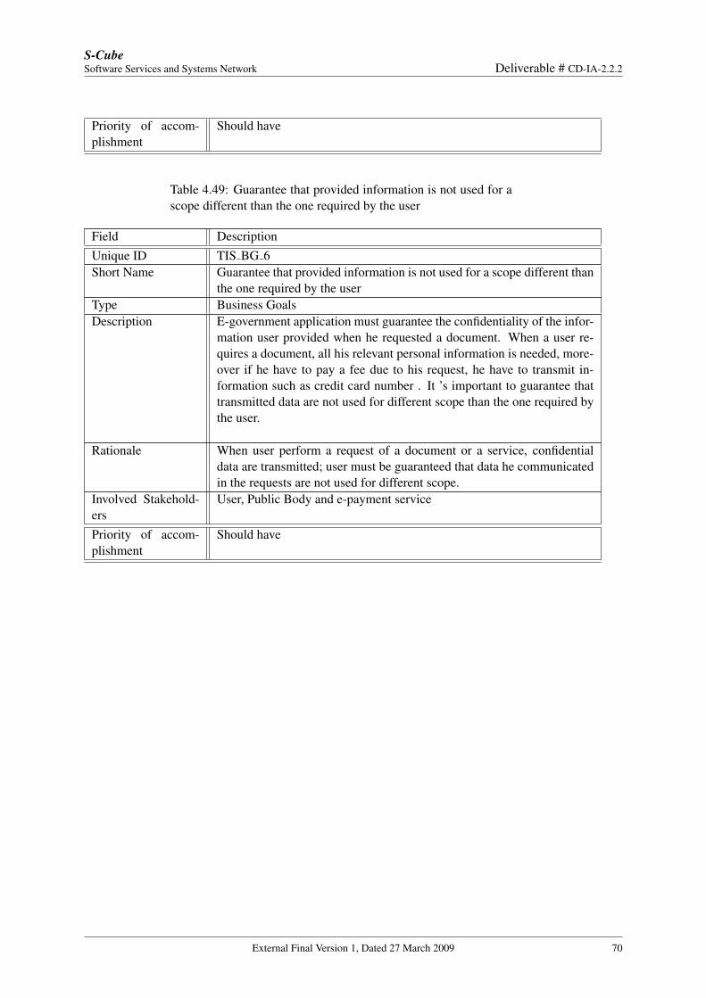
S-CubeSoftware Services and Systems Network Deliverable # CD-IA-2.2.2
Priority of accom-plishment
Should have
Table 4.49: Guarantee that provided information is not used for ascope different than the one required by the user
Field DescriptionUnique ID TIS BG 6Short Name Guarantee that provided information is not used for a scope different than
the one required by the userType Business GoalsDescription E-government application must guarantee the confidentiality of the infor-
mation user provided when he requested a document. When a user re-quires a document, all his relevant personal information is needed, more-over if he have to pay a fee due to his request, he have to transmit in-formation such as credit card number . It ’s important to guarantee thattransmitted data are not used for different scope than the one required bythe user.
Rationale When user perform a request of a document or a service, confidentialdata are transmitted; user must be guaranteed that data he communicatedin the requests are not used for different scope.
Involved Stakehold-ers
User, Public Body and e-payment service
Priority of accom-plishment
Should have
External Final Version 1, Dated 27 March 2009 70
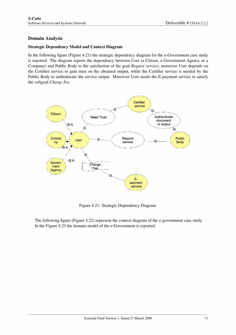
S-CubeSoftware Services and Systems Network Deliverable # CD-IA-2.2.2
Domain Analysis
Strategic Dependency Model and Context Diagram
In the following figure (Figure 4.21) the strategic dependency diagram for the e-Government case studyis reported. The diagram reports the dependency between User (a Citizen, a Government Agency or aCompany) and Public Body to the satisfaction of the goal Require service; moreover User depends onthe Certifier service to gain trust on the obtained output, while the Certifier service is needed by thePublic Body to authenticate the service output. Moreover User needs the E-payment service to satisfythe softgoal Charge Fee.
Figure 4.21: Strategic Dependency Diagram
The following figure (Figure 4.22) represent the context diagram of the e-government case study.In the Figure 4.23 the domain model of the e-Government is reported.
External Final Version 1, Dated 27 March 2009 71
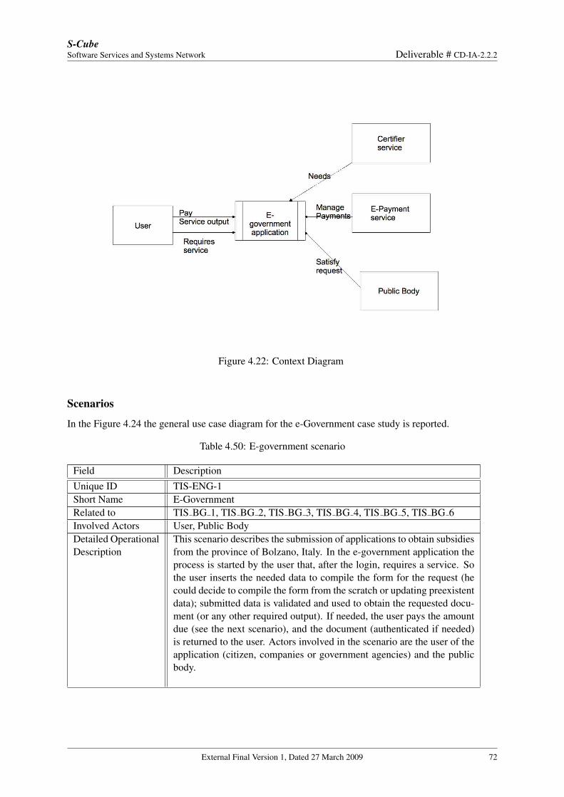
S-CubeSoftware Services and Systems Network Deliverable # CD-IA-2.2.2
Figure 4.22: Context Diagram
Scenarios
In the Figure 4.24 the general use case diagram for the e-Government case study is reported.
Table 4.50: E-government scenario
Field DescriptionUnique ID TIS-ENG-1Short Name E-GovernmentRelated to TIS BG 1, TIS BG 2, TIS BG 3, TIS BG 4, TIS BG 5, TIS BG 6Involved Actors User, Public BodyDetailed OperationalDescription
This scenario describes the submission of applications to obtain subsidiesfrom the province of Bolzano, Italy. In the e-government application theprocess is started by the user that, after the login, requires a service. Sothe user inserts the needed data to compile the form for the request (hecould decide to compile the form from the scratch or updating preexistentdata); submitted data is validated and used to obtain the requested docu-ment (or any other required output). If needed, the user pays the amountdue (see the next scenario), and the document (authenticated if needed)is returned to the user. Actors involved in the scenario are the user of theapplication (citizen, companies or government agencies) and the publicbody.
External Final Version 1, Dated 27 March 2009 72
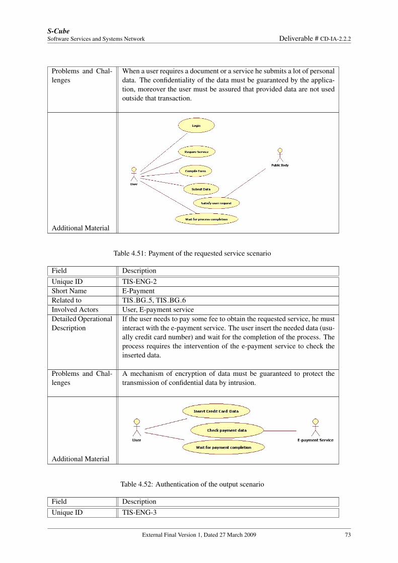
S-CubeSoftware Services and Systems Network Deliverable # CD-IA-2.2.2
Problems and Chal-lenges
When a user requires a document or a service he submits a lot of personaldata. The confidentiality of the data must be guaranteed by the applica-tion, moreover the user must be assured that provided data are not usedoutside that transaction.
Additional Material
Table 4.51: Payment of the requested service scenario
Field DescriptionUnique ID TIS-ENG-2Short Name E-PaymentRelated to TIS BG 5, TIS BG 6Involved Actors User, E-payment serviceDetailed OperationalDescription
If the user needs to pay some fee to obtain the requested service, he mustinteract with the e-payment service. The user insert the needed data (usu-ally credit card number) and wait for the completion of the process. Theprocess requires the intervention of the e-payment service to check theinserted data.
Problems and Chal-lenges
A mechanism of encryption of data must be guaranteed to protect thetransmission of confidential data by intrusion.
Additional Material
Table 4.52: Authentication of the output scenario
Field DescriptionUnique ID TIS-ENG-3
External Final Version 1, Dated 27 March 2009 73
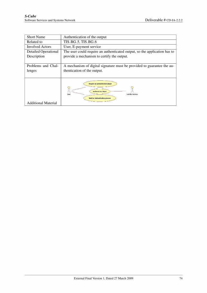
S-CubeSoftware Services and Systems Network Deliverable # CD-IA-2.2.2
Short Name Authentication of the outputRelated to TIS BG 5, TIS BG 6Involved Actors User, E-payment serviceDetailed OperationalDescription
The user could require an authenticated output, so the application has toprovide a mechanism to certify the output.
Problems and Chal-lenges
A mechanism of digital signature must be provided to guarantee the au-thentication of the output.
Additional Material
External Final Version 1, Dated 27 March 2009 74
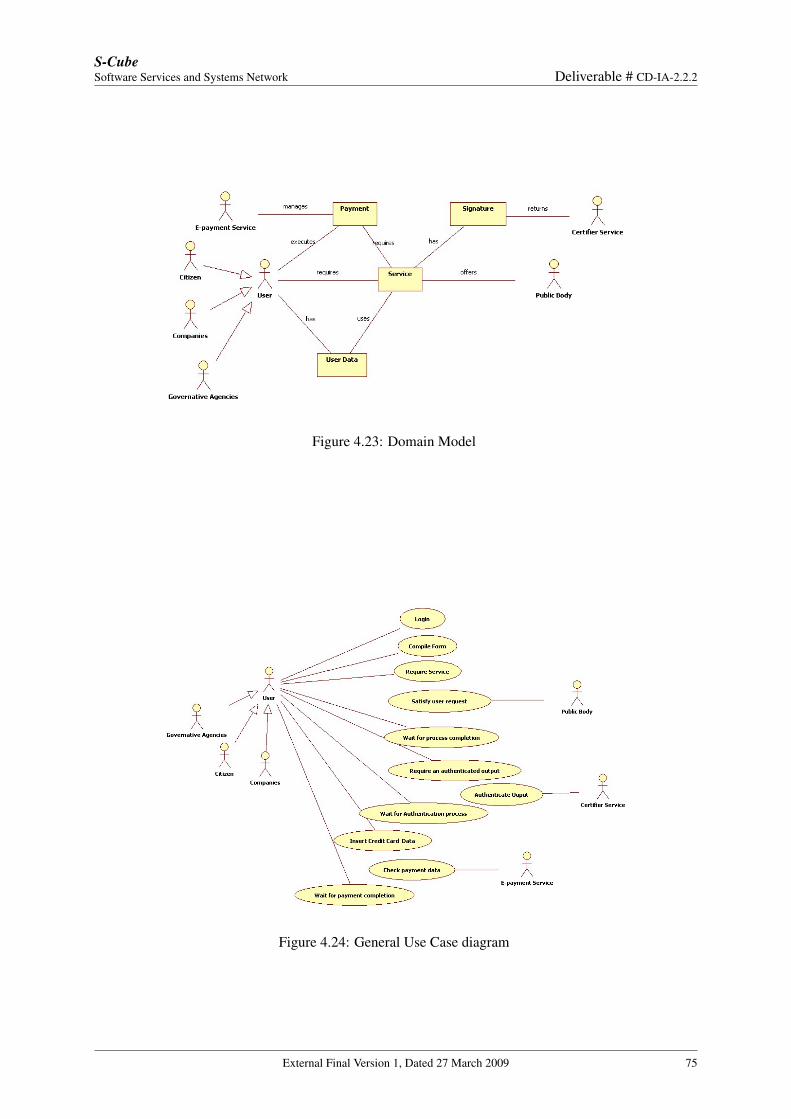
S-CubeSoftware Services and Systems Network Deliverable # CD-IA-2.2.2
Figure 4.23: Domain Model
Figure 4.24: General Use Case diagram
External Final Version 1, Dated 27 March 2009 75
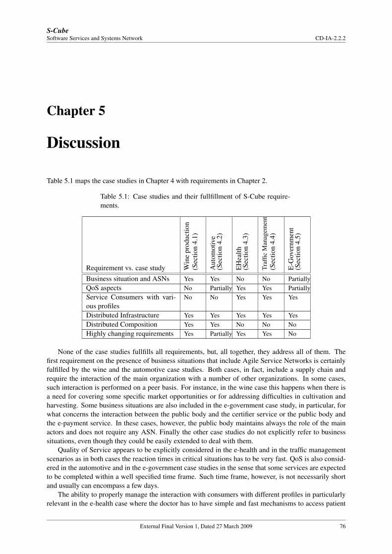
S-CubeSoftware Services and Systems Network CD-IA-2.2.2
Chapter 5
Discussion
Table 5.1 maps the case studies in Chapter 4 with requirements in Chapter 2.
Table 5.1: Case studies and their fullfillment of S-Cube require-ments.
Requirement vs. case study Win
epr
oduc
tion
(Sec
tion
4.1)
Aut
omot
ive
(Sec
tion
4.2)
EH
ealth
(Sec
tion
4.3)
Traf
ficM
anag
emen
t(S
ectio
n4.
4)
E-G
over
nmen
t(S
ectio
n4.
5)
Business situation and ASNs Yes Yes No No PartiallyQoS aspects No Partially Yes Yes PartiallyService Consumers with vari-ous profiles
No No Yes Yes Yes
Distributed Infrastructure Yes Yes Yes Yes YesDistributed Composition Yes Yes No No NoHighly changing requirements Yes Partially Yes Yes No
None of the case studies fullfills all requirements, but, all together, they address all of them. Thefirst requirement on the presence of business situations that include Agile Service Networks is certainlyfulfilled by the wine and the automotive case studies. Both cases, in fact, include a supply chain andrequire the interaction of the main organization with a number of other organizations. In some cases,such interaction is performed on a peer basis. For instance, in the wine case this happens when there isa need for covering some specific market opportunities or for addressing difficulties in cultivation andharvesting. Some business situations are also included in the e-government case study, in particular, forwhat concerns the interaction between the public body and the certifier service or the public body andthe e-payment service. In these cases, however, the public body maintains always the role of the mainactors and does not require any ASN. Finally the other case studies do not explicitly refer to businesssituations, even though they could be easily extended to deal with them.
Quality of Service appears to be explicitly considered in the e-health and in the traffic managementscenarios as in both cases the reaction times in critical situations has to be very fast. QoS is also consid-ered in the automotive and in the e-government case studies in the sense that some services are expectedto be completed within a well specified time frame. Such time frame, however, is not necessarily shortand usually can encompass a few days.
The ability to properly manage the interaction with consumers with different profiles in particularlyrelevant in the e-health case where the doctor has to have simple and fast mechanisms to access patient
External Final Version 1, Dated 27 March 2009 76
S-CubeSoftware Services and Systems Network Deliverable # CD-IA-2.2.2
information and to consult specialists while he/she is checking the patient. In this case, the user profileindicates the kind of devices being used by the operator and the situation in which he/she is working.In the traffic management case, different consumers, citizens, rescue force, and traffic manages havedifferent profiles as they differ in the role they cover and in the kinds of actions they are allowed to take.Therefore, the system has to be able to provide the right set of operations and access rights to all of them.In the e-government case the need for offering different interaction paradigms is not explicilty mentioned,but it is implicit in the business goal TIS BG 4 concerning the user experience. In order to offer a gooduser experience, in fact, it is not possible to assume that all citizens have the same requirements/needs.The user interface of the system will have to be adapted to the cultural background of the citizen, tohis/her abilities or disabilities.
The presence of a distributed infrastructure is important in almost all cases. In the wine productioncase the system includes a wireless sensor network to monitor the situation in the vineyard as well asother sensors and RFID systems to support harversting, maturation, and logistic. Moreover, the systemis able to interact with other external systems for monitoring and managing the fluctuation of marketneeds. In the automotive case the infrastructure is distributed as it includes the information systems ofthe various organizations involved in the case. In the e-health and in the traffic management cases thedistribution is due to the usage of non-conventional devices by the operators. Finally, the e-governmentcase does not explicitly indicate the need for distribution, but a few interaction with the payment and thecertifier services are foreseen.
Distributed composition is required in two cases of wine and automotive in which we have in placesome Agile Service Network.
Finally, highly changing requirements appear to be very important in the wine, e-health, and trafficmanagement cases where unforeseen situations are typical of the considered application domains. Theautomotive and e-government cases are more stable, but in the automotive case the possibility for taxationrules and regulations to change overtime is explicitly mentioned. It should be noticed that even in thesituations in which changing requirements are not foreseen at the application level, they could be neededat the level of the solution that is used to address the case. Clearly, at this stage, we cannot consider thesesituations yet.
External Final Version 1, Dated 27 March 2009 77
S-CubeSoftware Services and Systems Network CD-IA-2.2.2
Chapter 6
Conclusion
The main objective of this report is to describe in a uniform format some case studies that are representa-tive of the panorama of service-based applications and could be used within S-Cube to experiment withthe results that will be produced by the various research workpackages.
In order to achieve the goal of the report, we have identified the interesting characteristics that a casestudy should have to be of interest for S-Cube; of course, these characteristics are the ones that highlightaspects on which S-Cube is developing research results. Moreover, we have defined a description formatfor case studies and we have exploited it to revisit and disambiguate five case studies that have beengathered from industry. In the final part of the deliverable we have compared the case studies against thecharacteristics we consider important. The conclusion we have achieved that, all together, these casescover all these characteristics, even though no one of them is able to cover all of them singularly.
External Final Version 1, Dated 27 March 2009 78
S-CubeSoftware Services and Systems Network CD-IA-2.2.2
Bibliography
[1] “NESSI Open Framework - Reference Architecture (NEXOF-RA): Scenarios and Requirementsfor Open Framework Construction,” http://www.nexof-ra.eu/?q=rep/term/200.
[2] M. Jackson and P. Zave, “Deriving specifications from requirements: An example,” in ICSE, 1995,pp. 15–24.
[3] “i-star software formalism,” http://www.ics.uci.edu/∼alspaugh/software/istar.html.
[4] M. Jackson, Software requirements & specifications: a lexicon of practice, principles and preju-dices. New York, NY, USA: ACM Press/Addison-Wesley Publishing Co., 1995.
[5] “Donnafugata website,” http://www.donnafugata.it/.
[6] “ArtDeco: Adaptive Infrastructures for Decentralised Organizations,” http://artdeco.elet.polimi.it/.
[7] J. Sairamesh, S. Zeng, B. J. Steele, and M. A. Cohen, “Dynamic service networks: Case study onsupply-chain collaboration for early detection and recovery through information services,” technicalreport available from S-Cube on request.
[8] “SCOR Reference Model, Supply Chain Council,” http://www.supply-chain.org/.
[9] “RosettaNet PIP,” http://www.rosettanet.org/cms/sites/RosettaNet/Standards/RStandards/.
[10] “Siemens website,” http//w1.siemens.com.
[11] “Thales website,” http://www.thalesgroup.com/.
[12] “Engineering website,” http://www.eng.it/.
[13] “TIS Innovation Park website,” http://www.tis.bz.it/.
External Final Version 1, Dated 27 March 2009 79