Embed Size (px)
Citation preview
i
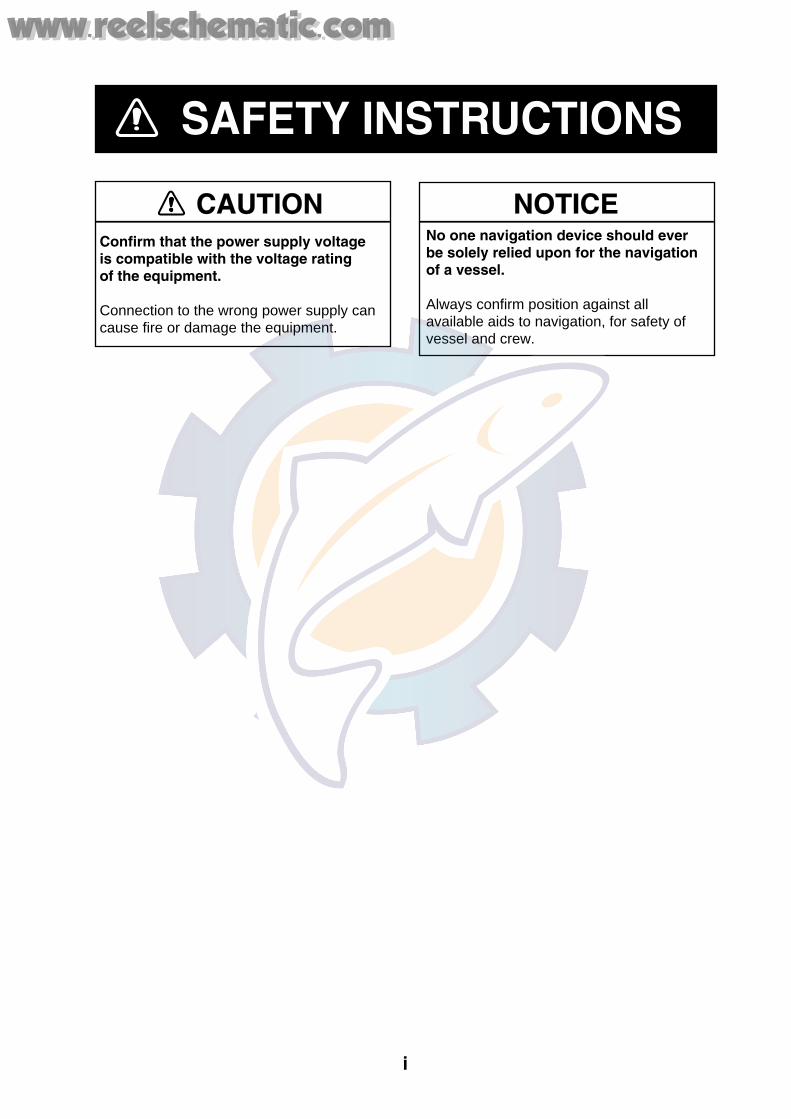
SAFETY INSTRUCTIONS
Confirm that the power supply voltage is compatible with the voltage ratingof the equipment.
Connection to the wrong power supply can cause fire or damage the equipment.
CAUTION NOTICENo one navigation device should ever be solely relied upon for the navigation of a vessel.
Always confirm position against all available aids to navigation, for safety of vessel and crew.
www.reelschematic.comwww.reelschematic.com
ii
TABLE OF CONTENTS
SYSTEM OVERVIEW........................................................................................... iii EQUIPMENT LISTS .............................................................................................. v
1. MOUNTING ....................................................................................................... 1
2. WIRING ............................................................................................................. 2
3. DEFAULT SETTINGS ....................................................................................... 6
4. TROUBLESHOOTING, BATTERY ................................................................... 7
SPECIFICATIONS........................................................................................... SP-1
PACKING LIST OUTLINE DRAWING Declaration of Conformity
www.reelschematic.comwww.reelschematic.com
iii
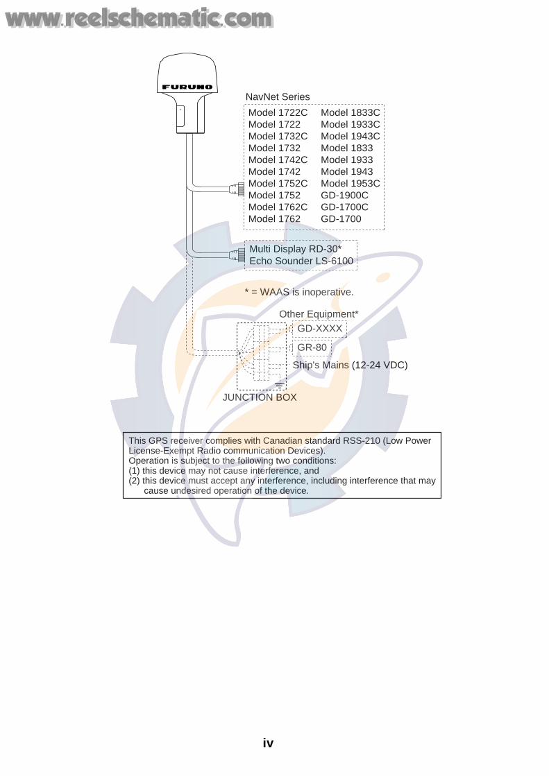
SYSTEM OVERVIEW
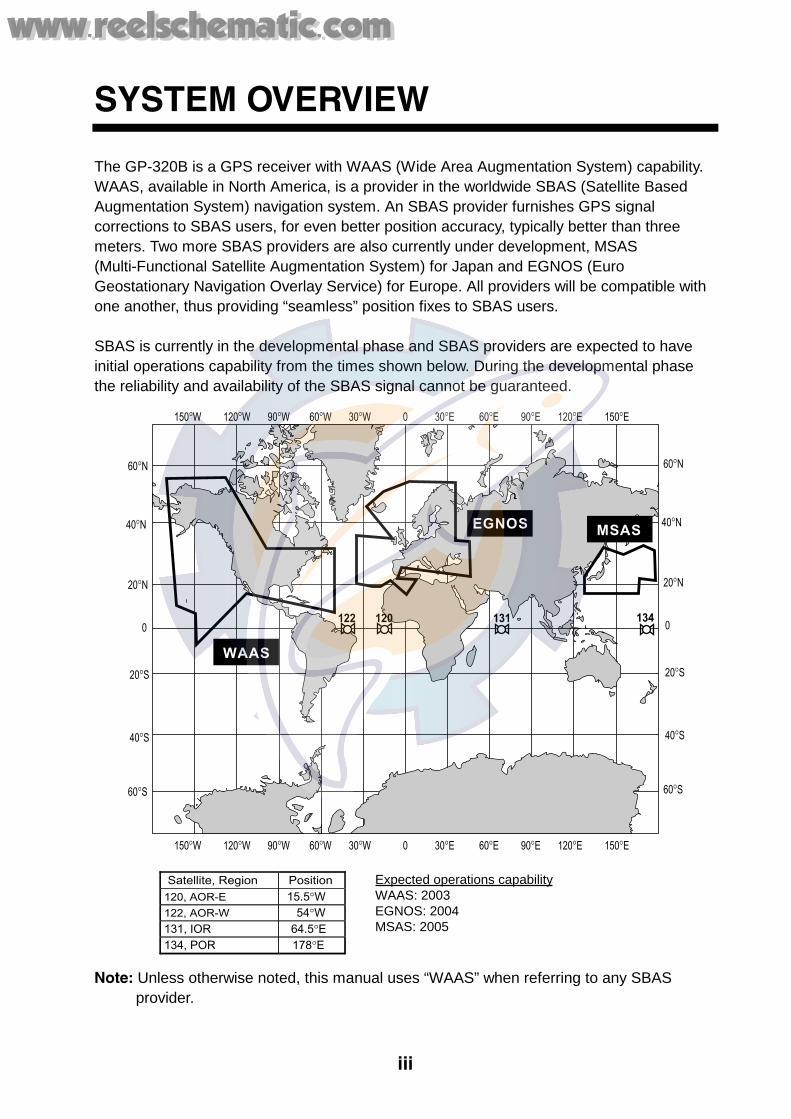
The GP-320B is a GPS receiver with WAAS (Wide Area Augmentation System) capability. WAAS, available in North America, is a provider in the worldwide SBAS (Satellite Based Augmentation System) navigation system. An SBAS provider furnishes GPS signal corrections to SBAS users, for even better position accuracy, typically better than three meters. Two more SBAS providers are also currently under development, MSAS (Multi-Functional Satellite Augmentation System) for Japan and EGNOS (Euro Geostationary Navigation Overlay Service) for Europe. All providers will be compatible with one another, thus providing “seamless” position fixes to SBAS users. SBAS is currently in the developmental phase and SBAS providers are expected to have initial operations capability from the times shown below. During the developmental phase the reliability and availability of the SBAS signal cannot be guaranteed.
150°W 120°W 90°W 60°W 30°W 0 30°E 60°E 90°E 120°E 150°E
150°W 120°W 90°W 60°W 30°W 0 30°E 60°E 90°E 120°E 150°E
0
20°S
40°S
60°S
20°N
40°N
60°N
0
20°S
40°S
60°S
20°N
40°N
60°N
WAAS
EGNOS MSAS
Satellite, Region Position
120, AOR-E 15.5°W 122, AOR-W 54°W
131, IOR 64.5°E
134, POR 178°E
131 134122 120
Expected operations capabilityWAAS: 2003EGNOS: 2004MSAS: 2005
Note: Unless otherwise noted, this manual uses “WAAS” when referring to any SBAS provider.
www.reelschematic.comwww.reelschematic.com
iv
Other Equipment*
JUNCTION BOX
GD-XXXX
GR-80
Ship's Mains (12-24 VDC)
Multi Display RD-30*Echo Sounder LS-6100
NavNet Series
Model 1722C Model 1833CModel 1722 Model 1933CModel 1732C Model 1943CModel 1732 Model 1833Model 1742C Model 1933Model 1742 Model 1943Model 1752C Model 1953CModel 1752 GD-1900CModel 1762C GD-1700CModel 1762 GD-1700
* = WAAS is inoperative.
This GPS receiver complies with Canadian standard RSS-210 (Low PowerLicense-Exempt Radio communication Devices).Operation is subject to the following two conditions:(1) this device may not cause interference, and(2) this device must accept any interference, including interference that may cause undesired operation of the device.
www.reelschematic.comwww.reelschematic.com
v
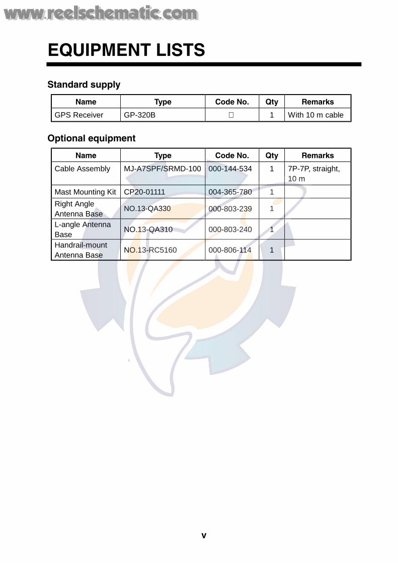
EQUIPMENT LISTS
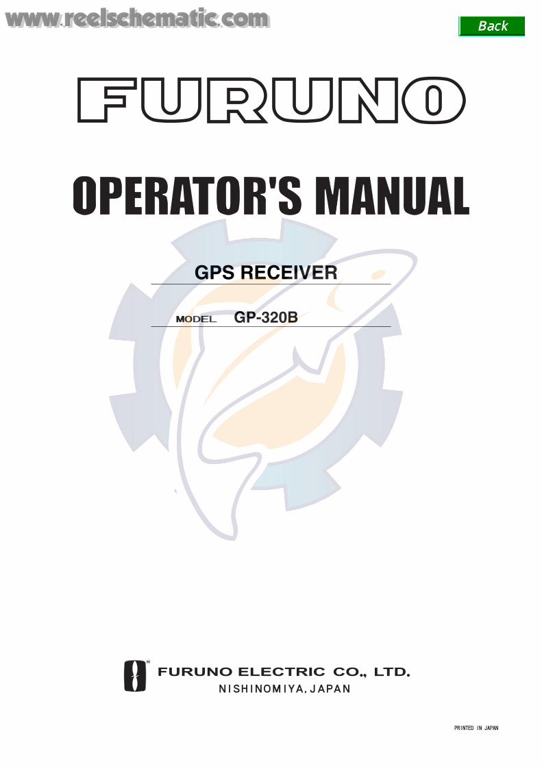
Standard supply
Name Type Code No. Qty Remarks
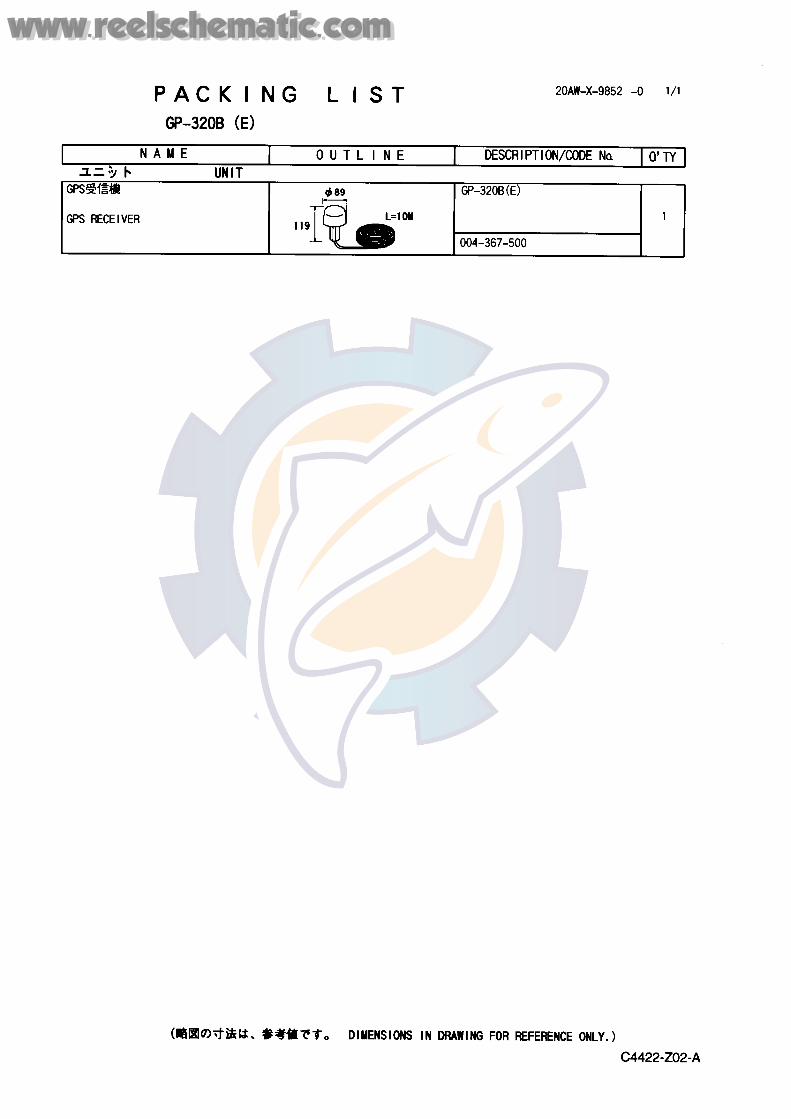
GPS Receiver GP-320B 1 With 10 m cable
Optional equipment
Name Type Code No. Qty Remarks
Cable Assembly MJ-A7SPF/SRMD-100 000-144-534 1 7P-7P, straight, 10 m
Mast Mounting Kit CP20-01111 004-365-780 1
Right Angle Antenna Base
NO.13-QA330 000-803-239 1
L-angle Antenna Base
NO.13-QA310 000-803-240 1
Handrail-mount Antenna Base
NO.13-RC5160 000-806-114 1
www.reelschematic.comwww.reelschematic.com

vi
(This page intentionally left blank.)
www.reelschematic.comwww.reelschematic.com

1
1. MOUNTING
Mounting considerations Follow the guidelines below to choose a suitable mounting location for the antenna unit. • The antenna may be mounted three ways: screwed into a pipe (local supply), fixed to a
post with the optional mast mounting kit, or screwed into an optional mounting base. For fixing by the post or pipe, it is recommended to use stays to prevent damage to the GPS receiver.
• Select a location out of the radar beam. The radar beam will obstruct or prevent reception of the GPS signal.
• The location should be well away from a VHF antenna. A GPS receiver is interfered by a harmonic wave of a VHF antenna.
• The location should be well away from an Inmarsat antenna. Inmarsat transmission will obstruct or prevent reception of the GPS signal.
• There should be no interfering object within the line-of-sight to the satellites. Objects within line-of-sight to a satellite, for example, a mast, may block reception or prolong acquisition time.
• Mount the antenna unit as high as possible to keep it free of interfering objects and water spray, which can obstruct reception of the GPS signal if the water freezes.
• Observe the following minimum separation distances from other antenna units.
a
1.5 m
MAIN MAST
TX ANTENNA(MF/HF)
NOT WITHIN RADAR BEAM
* = DISTANCE DEPENDS ON MAST DIAMETER OF ’a’.
4 m4 m
1 m1 m3 m
INMARSAT ANTENNA
LOOP ANTENNA
RX WHIP ANTENNA
5 m NOT WITHIN INMARSAT BEAM
0.5 m
WHIP ANTENNA(VHF/UHF) WHIP ANTENNA(MF/HF)
GPS ANTENNA
DIA. OF ’a’ DISTANCE (MIN.)
3 m1.5 m10 cm
30 cm
*
Mounting procedure Install the antenna unit by referring to the installation diagram on page D-1.
www.reelschematic.comwww.reelschematic.com
2
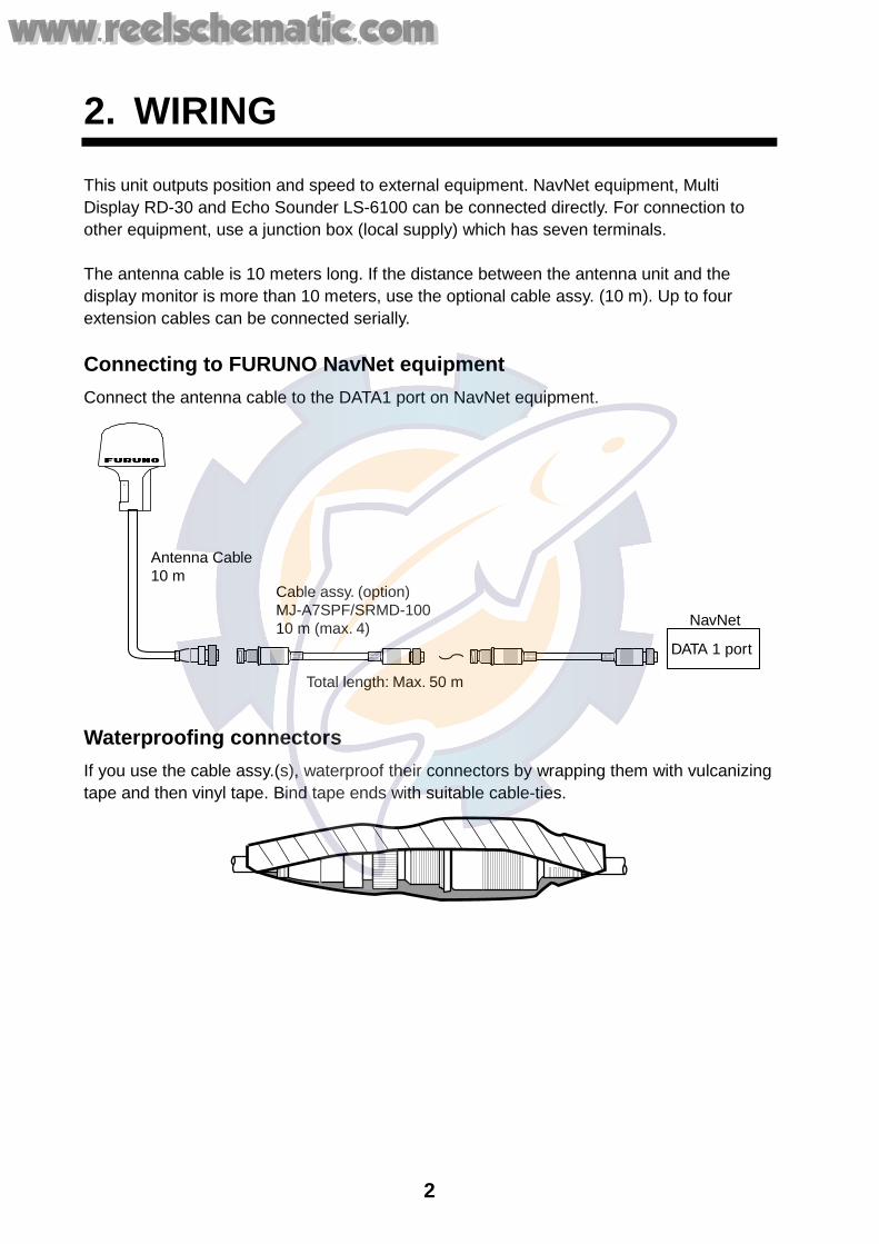
2. WIRING This unit outputs position and speed to external equipment. NavNet equipment, Multi Display RD-30 and Echo Sounder LS-6100 can be connected directly. For connection to other equipment, use a junction box (local supply) which has seven terminals. The antenna cable is 10 meters long. If the distance between the antenna unit and the display monitor is more than 10 meters, use the optional cable assy. (10 m). Up to four extension cables can be connected serially. Connecting to FURUNO NavNet equipment Connect the antenna cable to the DATA1 port on NavNet equipment.
Total length: Max. 50 m
Cable assy. (option)MJ-A7SPF/SRMD-10010 m (max. 4)
Antenna Cable10 m
DATA 1 port
NavNet
Waterproofing connectors If you use the cable assy.(s), waterproof their connectors by wrapping them with vulcanizing tape and then vinyl tape. Bind tape ends with suitable cable-ties.
www.reelschematic.comwww.reelschematic.com
3
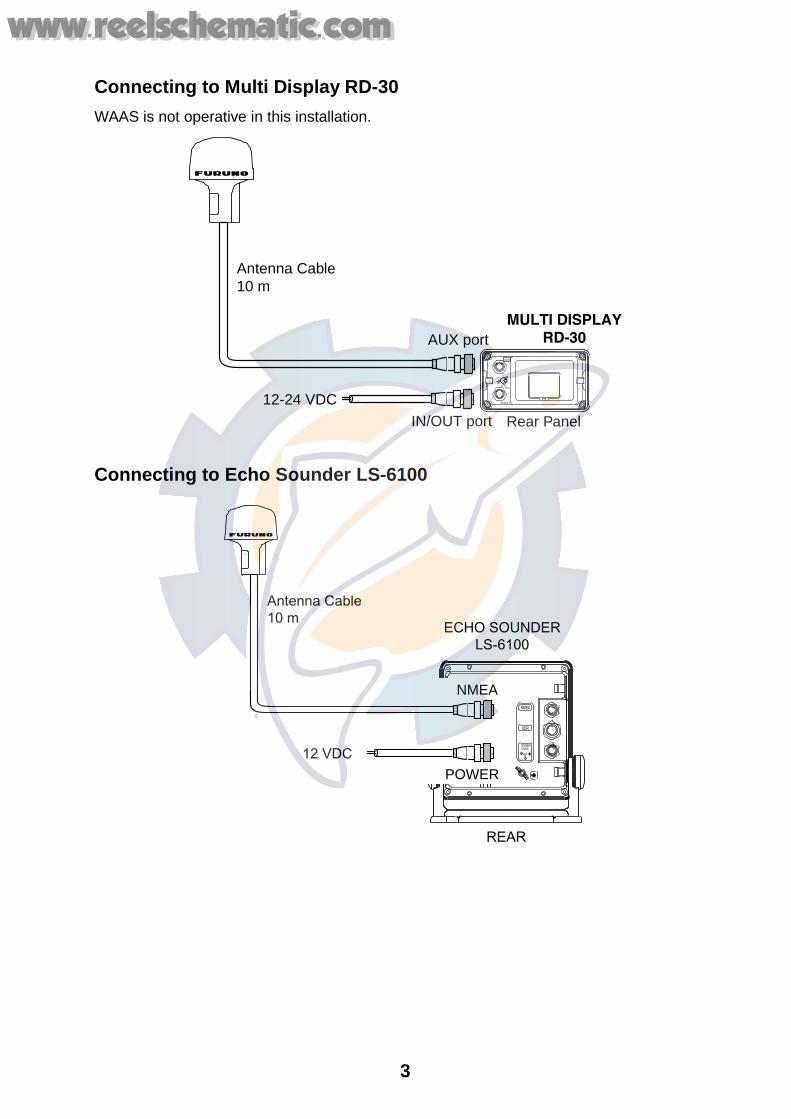
Connecting to Multi Display RD-30 WAAS is not operative in this installation.
Antenna Cable10 m
MULTI DISPLAYRD-30AUX port
IN/OUT port
12-24 VDC
AUX
IN/OUT
12-24VDC
Rear Panel
Connecting to Echo Sounder LS-6100
Antenna Cable10 m
ECHO SOUNDERLS-6100
REAR
NMEA
XDR
POWER12VDC
POWER
12 VDC
NMEA
www.reelschematic.comwww.reelschematic.com
4
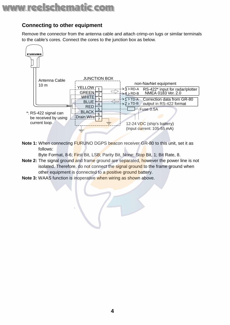
Connecting to other equipment Remove the connector from the antenna cable and attach crimp-on lugs or similar terminals to the cable’s cores. Connect the cores to the junction box as below.
Antenna Cable10 m non-NavNet equipment
RS-422* input for radar/plotter
Correction data from GR-80output in RS-422 format
12-24 VDC (ship's battery)(Input current: 105-55 mA)
NMEA 0183 Ver. 2.0
*: RS-422 signal canbe received by usingcurrent loop.
1234567
WHITE
BLACK
YELLOW
JUNCTION BOX
GREEN
REDBLUE
Drain Wire
12
34
Fuse 0.5A
RD-ARD-B
TD-ATD-B
Note 1: When connecting FURUNO DGPS beacon receiver GR-80 to this unit, set it as
follows: Byte Format, 8-6; First Bit, LSB; Parity Bit, None; Stop Bit, 1; Bit Rate, 8.
Note 2: The signal ground and frame ground are separated, however the power line is not isolated. Therefore, do not connect the signal ground to the frame ground when other equipment is connected to a positive ground battery.
Note 3: WAAS function is inoperative when wiring as shown above.
www.reelschematic.comwww.reelschematic.com
5
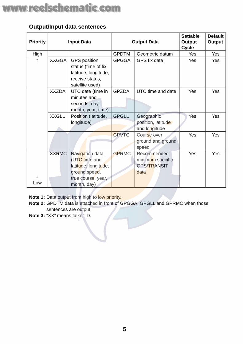
Output/Input data sentences
Priority Input Data Output Data Settable Output Cycle
Default Output
GPDTM Geometric datum Yes Yes XXGGA GPS position
status (time of fix, latitude, longitude, receive status, satellite used)
GPGGA GPS fix data Yes Yes
XXZDA UTC date (time in minutes and seconds, day, month, year, time)
GPZDA UTC time and date Yes Yes
XXGLL Position (latitude, longitude)
GPGLL Geographic position, latitude and longitude
Yes Yes
GPVTG Course over ground and ground speed
Yes Yes
High ↑
↓ Low
XXRMC Navigation data (UTC time and latitude, longitude, ground speed, true course, year, month, day)
GPRMC Recommended minimum specific GPS/TRANSIT data
Yes Yes
Note 1: Data output from high to low priority. Note 2: GPDTM data is attached in front of GPGGA, GPGLL and GPRMC when those
sentences are output. Note 3: “XX” means talker ID.
www.reelschematic.comwww.reelschematic.com
6
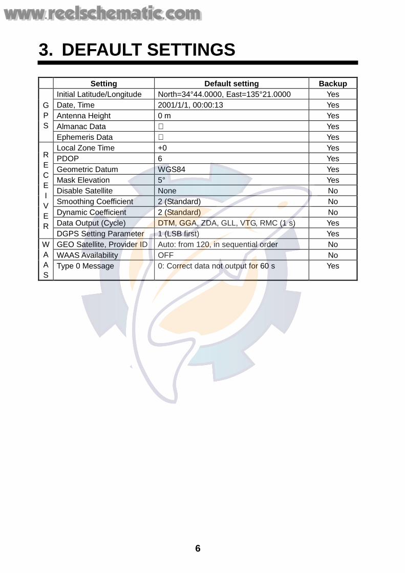
3. DEFAULT SETTINGS Setting Default setting Backup
Initial Latitude/Longitude North=34°44.0000, East=135°21.0000 Yes Date, Time 2001/1/1, 00:00:13 Yes Antenna Height 0 m Yes Almanac Data Yes
G P S
Ephemeris Data Yes Local Zone Time +0 Yes PDOP 6 Yes Geometric Datum WGS84 Yes Mask Elevation 5° Yes Disable Satellite None No Smoothing Coefficient 2 (Standard) No Dynamic Coefficient 2 (Standard) No Data Output (Cycle) DTM, GGA, ZDA, GLL, VTG, RMC (1 s) Yes
R E C E IV E R
DGPS Setting Parameter 1 (LSB first) Yes GEO Satellite, Provider ID Auto: from 120, in sequential order No WAAS Availability OFF No
W A A S
Type 0 Message 0: Correct data not output for 60 s Yes
www.reelschematic.comwww.reelschematic.com
7
4. TROUBLESHOOTING, BATTERY
Troubleshooting If the message “No position data” appears on the display of NavNet equipment, there may be a problem with the GPS receiver. Turn off the power and then check the following points: 1) Check for objects around the antenna which may interfere with reception. 2) Check that the antenna cable is firmly fastened. 3) If extension cable(s) are used, check for water leakage at junction point(s). 4) Check the antenna cable for damage. 5) Check the antenna for damage.
If the problem seems to be with the antenna cable or antenna, contact your dealer. Battery The antenna unit contains a lithium battery which preserves data when the power is turned off, and its life is approximately 20 years (operating rate 70%) for large vessels and 10 years (operating rate 20%) for small vessels. The equipment can be used when the voltage of the battery is low, however data is not backed up and the unit starts up in the “cold start” condition.
www.reelschematic.comwww.reelschematic.com
SP - 1 E4422S01A
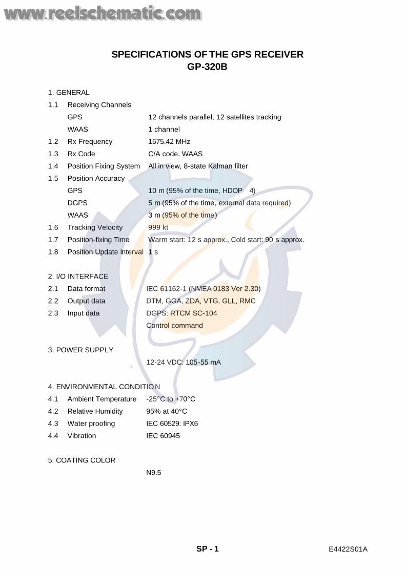
SPECIFICATIONS OF THE GPS RECEIVER GP-320B
1. GENERAL
1.1 Receiving Channels
GPS 12 channels parallel, 12 satellites tracking
WAAS 1 channel
1.2 Rx Frequency 1575.42 MHz
1.3 Rx Code C/A code, WAAS
1.4 Position Fixing System All in view, 8-state Kalman filter
1.5 Position Accuracy
GPS 10 m (95% of the time, HDOP� 4)
DGPS 5 m (95% of the time, external data required)
WAAS 3 m (95% of the time)
1.6 Tracking Velocity 999 kt
1.7 Position-fixing Time Warm start: 12 s approx., Cold start: 90 s approx.
1.8 Position Update Interval 1 s
2. I/O INTERFACE
2.1 Data format IEC 61162-1 (NMEA 0183 Ver 2.30)
2.2 Output data DTM, GGA, ZDA, VTG, GLL, RMC
2.3 Input data DGPS: RTCM SC-104
Control command
3. POWER SUPPLY
12-24 VDC: 105-55 mA
4. ENVIRONMENTAL CONDITIO N
4.1 Ambient Temperature -25°C to +70°C
4.2 Relative Humidity 95% at 40°C
4.3 Water proofing IEC 60529: IPX6
4.4 Vibration IEC 60945
5. COATING COLOR
N9.5
www.reelschematic.comwww.reelschematic.com

The paper used in this manual
is elemental chlorine free.
FURUNO Authorized Distributor/DealerFURUNO Authorized Distributor/Dealer
9-52 Ashihara-cho,9-52 Ashihara-cho,Nishinomiya 662-8580, JAPANNishinomiya 662-8580, JAPAN
Telephone :Telephone : 0798-65-21110798-65-2111FaxFax 0798-65-42000798-65-4200::
FIRST EDITION :FIRST EDITION : APR.APR. 20022002Printed in JapanPrinted in JapanAll rights reserved.All rights reserved.B1B1 :: APR.APR. 12, 200512, 2005
Pub. No.Pub. No. OME-44220OME-44220*00080929110**00080929110**00080929110**00080929110*(( TATATATA )) GP-320BGP-320B
* 0 0 0 8 0 9 2 9 1 1 0 ** 0 0 0 8 0 9 2 9 1 1 0 *
*OME44220B10**OME44220B10**OME44220B10**OME44220B10*
* O M E 4 4 2 2 0 B 1 0 ** O M E 4 4 2 2 0 B 1 0 *
www.reelschematic.comwww.reelschematic.com