Embed Size (px)
Citation preview

Government Recognized Export House | OHSAS 18001:2007 | ISO 14001:2004 | PED Approved Company.
Phone : +91 22 4343 1313 (25 Lines) | Fax : +91 22 2389 4311 Email : [email protected] | [email protected]
metałłic Flat Gaskets
pe Fłanges
metallic Flat Gaskets for
Flanges
A N A M E R ICA N NAT IONA L STA N DA R D
ASfüEBl6 .2î-2005 (Revision of ASME B16.21-1992)
0aTe of issuance: May 31, 2005
The next edition of this Standard is scheduled for pubtica tion in 2010. There will be no addenda issued
to this edition.
ASME issues written replies to inquiries concerning interpretations of te€hnica I aspects of this Stan•
da rd. Interpretations a re published on the ASME Web site under the Committee Pa Yes at
http://www.as me.o rg/codes / as they are issued.
ASME is the registered tradem a rk of Th e American 5ociely o I Mech anical En ginee rs.
This code or standard was developed u oder procedures acc redited as meeting the criteria for American National Stan-
dards. The Standards Co e ti uee thaf approved The code of standard was balanced to assure that indi \riduals from com-
petent and concerned interests have had an opportunity to participate. The proposed code or standard was made avail-
able for public review and comment that provides an opportunity for additional public input fTom industry, academia.
regulatory agencies, an6 the public at-lark. ASME does not ”approve,” “rate," or ”endorse” any item construction, proprietary device, or activity.
ASME does not take any position with respect to the validity of any patent rights asserted in connection with any items
mentioned in this document and does not undertal‹e to insure anyone utilizing a standard against liability for infringe-
ment of any applicable letters patent nor assume any such liability. Users of a code or standard are expressly advised
that determination of the validity of any such patent riff hts, and the risk of infringement of such rights, is entirely their
own responsibility.
Participation by federal agency representative(s] or person(s) affiliated with industry is not to be interpreted as Gov-
ernment or industry endorsement of this code or standard.
ASME accepts responsibility for only those interpretations of this document issued in accordance with the established
ASME procedures and policies, which precludes the issuance of interpretations by individuals.
to part of this document may be reproduced in any form,
in an electronic retrieval system or otherwise.
without the prior written permission of ltte publisher.
Th e American Society of Mecfiani cat Engineers
Th ree Pa rk Aden ue. New York, NY ROOT 6-5990
Co pyrigfit C' 2005 by
THE /\I\SEPIA AN SODI QTY O£ MECHAN I €AL £NGI NE£RS
API ri fffi fs reserved
Printed in IJ.S.A
CONTENTS
Foreword . . . . , . , . . , . . . , . . . . . . . . . . . . . . . . . . . . . . . . . . . . , . . . . . . . . . . . . . . . , . . . . , i
Comriuttee Roster ........................................................................................................................................................................ v
Correspondence With the B16 Committee ................................................................................................................... vi
1 Scope .... . .. . .... . .. . . .. .. . . . .. .. . .... \
2 Types and Sizes .......................................................................................................................................................... 1
3 Materials .. . .. . .. .. .. . .. ...... .. .... ............ .. . . 1
4 DimensionsandTolerances .. . .. . . .... . . .. .. . . 1
5 Markings ................................................................................................................................................................................................. 2
Tables 1 GasLet Dimensions for ASME B16. 1 Class 25, Cast Iron Age flanges rind
Flanged Fittings 2 2 Casket Dimensions for ASME B16.1 Class 125, Cast kon Pipe Flanges and
Ft:urged Fittings 3 Flat Ring Gasket Dimensions for ASME B16.1 Class 250, Cast Iron Pipe Flanges
and Flanged Fittings .......................................................................................................................................... 3 4 Gasket Dimensions for ASME B16.5 Class 150, Pipe Flanges and Flanged Fittings . 4 5 Flat Ring Gasket Dimensions for ASME B16.5 Pipe Flanges and Flanged Fittings,
Gasses 300 400, 600, and 900 . . 4 6 Full Face Gasket Dimensions for ASME B16.24, Cast Copper Alloy Pipe Flanges
and Flanged Fittings, Classes 150 and 300 . 5 7 Flat Ring Gasket Dimensions for ASME B16.47 Series A, Large Diameter Steel
Flanges, Classes 150, 300, 400, and 600 . . 8 Flat Ring Gasket Dimensions for ASME B16.4Z Series B, Large Diameter Steel
Flanges, Classes 75, 150, 300, 400, and 600 6
9 Full Face Gasket Dime:nsions for MSS sr-si Class 1S0LW, Corrosion-Resistant Cast Flanges and Flanged Fittings 6
Mandatory Appendices I Dimensions of Gaskets in U.S. Customary Units II References . .
Nonmandatory Appendix A Quality System Program
FOREWORD
Before tlfis standard o'as issued, the indiviclual sizes of gaskets were made to many different sets of dimensions, based on different concepts of adaptation and functional use on the part of consumers as well as manufacturers. In some cases dimensions were shown in American Stan— dards. To standardise gasket sizes, the Standards and Specifications Committee of the lvIechani- cal Pact:ing Association started work on a standard for nonmetallic or cut gaskets for bronze, iron, and steel pipe flanges.
Dimensions of gaskets being used were collected, and a basic design philosophy i F Chi:eg was formulated by the committee. This was the result of extensive field research experience and ac- cepted standard user requirements, The procedure followed was to dimension the gasket for each type and size of flange so as to prevent the gasket from projecting into the line of flow. Dimen- sional tolerances o£ standard pipe flanges and fittings as to I.D., O.D., and bolting were all con- sidered.
Suggested dimensional standards were tabulated anct distributed for industry comment. After several revisions, a firinl dra(I, dated September 15, 1948, was approved by the reason rank— ing Association for submission as an American Standard.
Sectional Committee (B16) on the Standardization of Pipe Flanges and fittings was organized in 1921 under the procedure of the American Standards Association, with the Heating, Piping, and Air Conditioning ContFacfors‘ National Association, Manufacturers’ Standardization Society of the Valve and Fittings Industry, and the American Society of Mechanical Engineers as joint
Sectional Committee B16 received the proposal on May 9, 1949, and assigned it to a joint group of Subcommikees 1 and 3. The Manufacturers’ Standardization Society was also consulted as the proposal included gaskets for bronze flanges made to their Standard Practice SP-2. Tlfis joint group offered a revision of the original design concept for sizing, \vIiicIa was acceptable to the Mechani- cal Packing Association’s Committee (now the Fluid Sealing Association). The Standard was ap- proved as an American Standard on Decerriber 5, 1951, with the designation ASA 1116.21-1951,
In 1961, the Standard was reviewed by the members of Subcommittee No. 7 on Gaskets and proposals for Tevision and updating the Standard were agreed upon. The American Standards Association granted approval of the res ision on March 20, 1962 following sectional corrimittee and sponsor approval.
In the mid-1960s, work had begun on a revision. The revision became a complete rewrite and included gaskets for API Std 605, MSS SPD and SP-51, as well as complete metric equivalents for all dimensions. Following its approval by the B16 Standards Committee and Co-Secretariat organizations, this Standard was approved as an American National Standard by ANSI on May 2, 1978.
In 1982, American National Standards Committee B16 was reorganized as an ASME Commit- tee operating urrder procedures accredited by ANSI.
In 1989, general revisions had begun to reflect the current size ranges covered by the corre— sponding flange standard. Gasket dimensions for tongue and groove, male and female Rating Classes above 900 were deleted because a survey indicated these nonmetallic gaskets were al- most never used for these joints. Tolerances to the dimensions were added.
Following approval by the Standards Committee and ASME, approval as an American Na- dorial Standard was given by ANSI on March 16, 1992, with the new designation ASME B16.21- 1992.
In 2005 the Standard adopted metric (SI) dimensions. Following approval by the B16 Sub- committee G, the B16 Standards Committee, and ASME, ANSI approved thrs American National Standard on March 16, 2005.
All requests for interpretation or suggestions for revisions should be sent to the Administra— tive Secretary B16, The American Society of Mechanical Engineers, Three Park Avenue, New Work, NY 10016-5990.
ASME B16 COMMITTEE
Standardization of Valves, Flanges, Fittings, and Gaskets
{The following is the roste r of the Tom mittee at the tim e of approval of this Stan dard.)
OFFICERS
R.W. Barnes, An ric Enterprises. Inc. W.N. McLean. Newco Valves
W.B. Bedesem. Exxon Mobil Research B Cn8ineeiing Co. T.A. M cMahon. Fisher Controls International, ] nc.
M. Ctac Nibco. In c. M. U ffayyar, Bechtel Power €orp.
C.E. £loren, Mu eller Co. ]. D. Page, LI.5. N u clear ftegu lato ry Co in in ission
D. g. £rikken, Becht Engineering P.A. Teddington. The Anne ri can Society of Mechanical Enginee is
G.G. Grills, BS Coast ?'u ard R.A. Schmidt, Trinity- Ladish
A. ttamilten, American Bureau of Shipping II. 11. Sondere r, Anvil International, Inc M. U Henderson, Forgital USA W.M. Stephan. L-lexitalli c LP
G. A jolly, Vogt Va l ves/ Flowse eve T.F. Stroud, Ducti le 7 ron Pipe Resea rch As sociatio n
M. hatcher, I-laynes lntern atio nal R.E. Whke, Richard E. Wh ite & Associates PC
W. G. KnechL Co nsu ltant D. Æ Williams, Southern Co. Services
SUBCOMMITTEE G — GASKETS FOR FLANGED POINTS
W. M. Stephan, Ch‹ ir, Rexitaltic Inc.
C.B. Glllis, Kee €//oir Tea dit N ortfi Am erica
K. Ä Benton, ] in Clip per 6a sket Division
W.E. Holden Solutia, Inc.
D.H. Monroe, Consu ltant
R.T. Mueller, Cons u ltant
P.S. Petrunl‹h. fluid Sealing Assoc.
M. e»lIock sraftech International D.F. Reid, 6arlock Metallic ?iasket Division
]. T. White, P u get Sound N avat 5hipya rd
CORRESPONDENCE WITH THE B16 COMMITTEE
General. ASME Standards are developed and maintained with be UtNt IO lR W6etlt lire 6U - sensus ot concerned interests. As such, users of this Standard may interact with the Committee by requesting interpretations, proposing revisions, and attending Committee meetings. Corre- spondence should be addressed to:
Secretary, B16 Standards Committee The American Society of Mechanical Engineers Three Park Avenue New York, NY 10016-5990
Prnpnsing Revisions. Revisions are made periodically to the Standard to incorporate changes that appear necessary or desirable, as demonstrated by the experience gained from the applica- tion of the Standard. Approved revisions will be published periodically.
The Committee welcomes proposals for revisions to this Standard. Such proposals should be as specific as possible, citing the paragraph number(s), the proposed wording, rind a detailed de- scription of the reasons for the proposal, including any pertinent documentation.
lilterpfetatJons. Upon request the B16 Committee will render an interpretation of any re- quirement of the Standard. Interpretations can only be rendered in response to a written request sent to the Secretary of the B16 Standards Committee.
The request for interpretation should be clear and unambiguous. It is further recommendecl that the Enquirer submit his/her request in the following format:
Subject: Cite the applicable paragraph number(s) and the topic of the inquiry. Edition: Cite the applicable edition of the Standard for which the interpretation is be—
ing requested. O_uestion: Phrase the question as a request for an uterpretation of a specific require-
ment suitable tor general understanding and use, not as a request for rim ap- proval of a proprietary design or situation. The Enquirer may also include any plans or drawings, which are necessary to explain the question; however, they should not contain proprietary names or information.
Requests that are not in this format will be rewritten i:n. this format by the Committee prior to being answered, which may inadvertently change the intent of the original request.
ASME procedures provide for reconsideration of any interpretation when or if additional in- formadon that might affect an interpretation is available, Further, persons aggrieved by an in- terpretation may appeal to the cog t ASME Coetzee or Subcommittee. ASME does not “approve,” “certify,” “rate,” or ”endorse” any item, construction, proprietary device, or acti ity.
Attending Committee Meetings. The B16 Standards Committee regularly holds meetings, which are open to the public. Persons wishing to attend any meeting should contact the Secretary of the B16 Standards Committee.
NONMETALLIC FLAT GASKETS FOR PIPE FLANGES
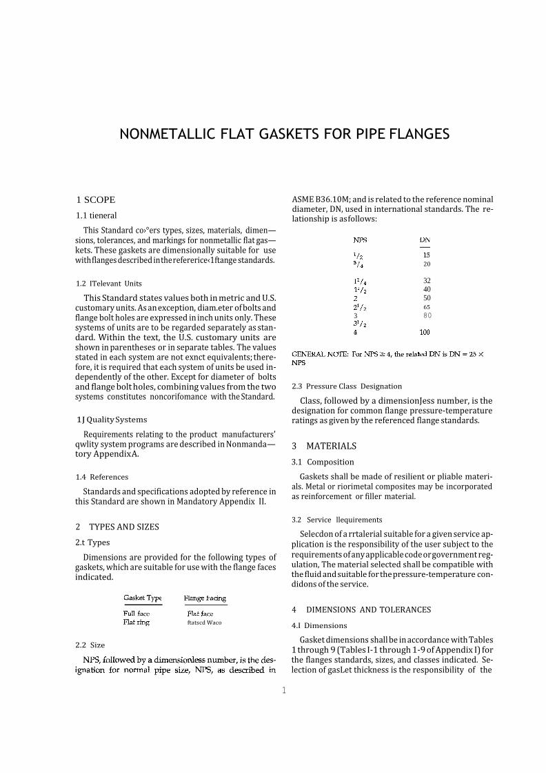
1 SCOPE
1.1 tieneral
This Standard co›°ers types, sizes, materials, dimen— sions, tolerances, and markings for nonmetallic flat gas— kets. These gaskets are dimensionally suitable for use with flanges described in the refererice‹1ftange standards.
1.2 ITelevant Units
This Standard states values both in metric and U.S. customary units. As an exception, diam.eter of bolts and flange bolt holes are expressed in inch units only. These systems of units are to be regarded separately as stan- dard. Within the text, the U.S. customary units are shown in parentheses or in separate tables. The values stated in each system are not exnct equivalents; there- fore, it is required that each system of units be used in- dependently of the other. Except for diameter of bolts and flange bolt holes, combining values from the two systems constitutes noncorifomance with the Standard.
1J Quality Systems
Requirements relating to the product manufacturers’ qwlity system programs are described in Nonmanda— tory Appendix A.
1.4 References
Standards and specifications adopted by reference in this Standard are shown in Mandatory Appendix II.
2 TYPES AND SIZES
2.t Types
Dimensions are provided for the following types of gaskets, which are suitable for use with the flange faces indicated.
ASME B36.10M; and is related to the reference nominal diameter, DN, used in international standards. The re- lationship is as follows:
20
32 40 50 65
3 80
2.3 Pressure Class Designation
Class, followed by a dimensionJess number, is the designation for common flange pressure-temperature ratings as given by the referenced flange standards.
3 MATERIALS
3.1 Composition
Gaskets shall be made of resilient or pliable materi- als. Metal or riorimetal composites may be incorporated as reinforcement or filler material.
3.2 Service llequirements
Selecdon of a rrtalerial suitable for a given service ap- plication is the responsibility of the user subject to the requirements of any applicable code or government reg- ulation, The material selected shall be compatible with the fluid and suitable for the pressure-temperature con- didons of the service.
2.2 Size
ftatscd Waco
4 DIMENSIONS AND TOLERANCES
4.I Dimensions
Gasket dimensions shall be in accordance with Tables 1 through 9 (Tables I-1 through 1-9 of Appendix I) for the flanges standards, sizes, and classes indicated. Se- lection of gasLet thickness is the responsibility of the
1
user, considering the properties of the gasket material as wcil as the intended service application.
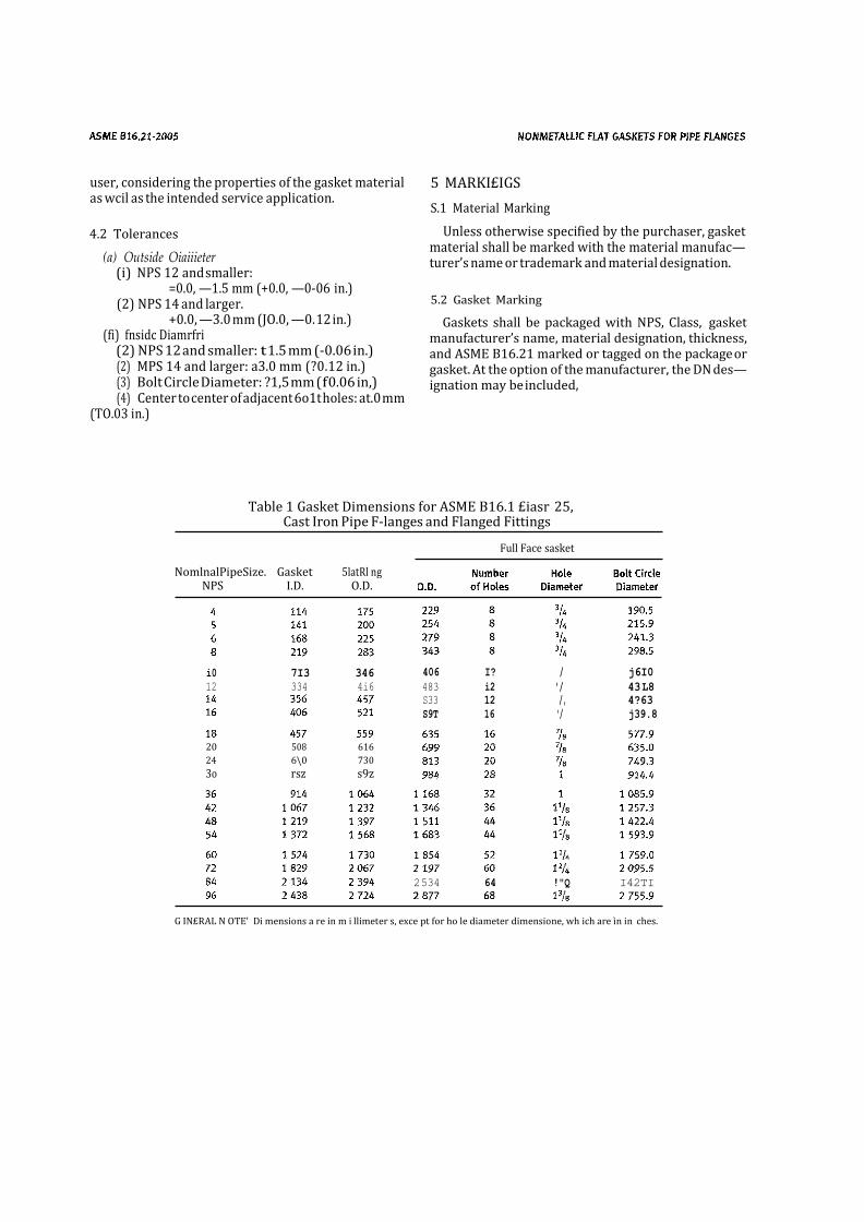
4.2 Tolerances
(a) Outside Oiaiiieter (i) NPS 12 and smaller:
=0.0, —1.5 mm (+0.0, —0-06 in.) (2) NPS 14 and larger.
+0.0, —3.0 mm (JO.0, —0. 12 in.) (fi) fnsidc Diamrfri
(2) NPS 12 and smaller: t 1.5 mm (-0.06 in.) (2) MPS 14 and larger: a3.0 mm (?0.12 in.) (3) Bolt Circle Diameter: ?1,5 mm ( f 0.06 in,) (4) Center to center of adjacent 6o1t holes: at.0 mm
(TO.03 in.)
5 MARKI£IGS
S.1 Material Marking
Unless otherwise specified by the purchaser, gasket material shall be marked with the material manufac— turer’s name or trademark and material designation.
5.2 Gasket Marking
Gaskets shall be packaged with NPS, Class, gasket manufacturer’s name, material designation, thickness, and ASME B16.21 marked or tagged on the package or gasket. At the option of the manufacturer, the DN des— ignation may be included,
Table 1 Gasket Dimensions for ASME B16.1 £iasr 25, Cast Iron Pipe F-langes and Flanged Fittings
Full Face sasket
i0 7I3 346
12 334 4i6
20 508 616
24 6\0 730
3o rsz s9z
406 I? / j6I0
483 i2 ’/ 43 L8
S33 12 /, 4?63
S9T 16 '/ j39.8
G IN£RAL N OTE' Di mensions a re in m i llimeter s, exce pt for ho le diameter dimensione, wh ich are ìn in ches.
2 534 64 !"Q I42TI
NomlnalPipeSize. Gasket 5latRl ng NPS I.D. O.D.
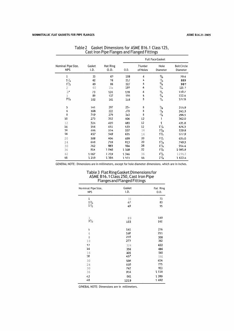
Table 2 Gasket Dimensions for ASME B16.1 Class 125, Cast Iron Pipe Flanges and Flanged Fittings
Full Face Gasket
Nominal Pipe Size.
NPS
Gasket
I.D.
Hat Ring
O.D.
O.D.
7\lumber
of Holes
Hole
Diameter
Bolt Circle
Diameter
33 6? 108
42 ?6 I1/
889
49 86 I2/
98?
2 60 10a 19?
120.?
2'/
3 89 137 191
102 161 1i6
297 25» 8
6
222 J79 8 8
279 3a3 8
12
16
16 20 20 24 20 30
36
42 36 1 29L3
GENERAL NOTE: Dimensions are in millimeters, except for hole diameter dimensions. which are in inches.
Table 3 Flat Ring Gasket Dimensions for
ASME B16.1 Class 250, Cast Iron Pipe Flanges and Flanged Fittings
No min at Pipe Size,
NPS
Gasket
I.D.
flat Ring
O.D.
33 73
83
95
3
89
i03
5
216
6
8
308
10
362
324 422
356 4B6
16 A06 540
59Z
30
24 775
30 953
36
061
1219
GfNEBAL NOTE: Dimensions are in millimeters.
AS NtE Bt6.22-2005
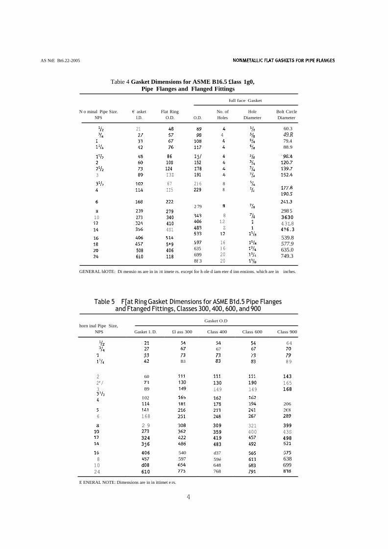
Tabie 4 Gasket Dimensions for ASME B16.5 £lass 1g0,
Pipe Flanges and Flanged Fittings
full face Gasket
N o minal Pipe Size. € asket Flat Ring
NPS I.D. O.D.
No. of Hole Bolt Circle
O.D. Holes Diameter Diameter
21
4
86 1j/
10S 152
124 I78
3 I3Z 191
67 2)6 8
II5 229 8
60.3
49.R 79.4
88.9
2 39
10 273
508
6i0
279
340
410
4S1
5*9
406
118
2 79
8
12 Z
16
635 )6
699 20
8f 3 20
298 5
3630
43L8
4?6.3
539.8 577.9 635.0 749.3
GENERAL hlOTE: Di mensio ns are in in i tt imete rs. except for h ole d iam eter d inn ensions. which are in inches.
Table 5 F[at Ring Gasket Dimensions for ASME B1d.5 Pipe Flanges and Ftanged Fittings, Classes 300, 400, 600, and 900
horn inal Pipe Size,
Gasket O.D
NPS Gasket 1. D. £l ass 300 Class 400 Class 600 Class 900
64
67
B3
89
2
60
143
2’/
130 130 190 165
3 89 149 i49 149 168
I 02
206
2€8
6 168
2 9 309 321 399
359 400 43S
324 419
498
3j6 483
406 540 d37
8
597 59é 638
10 d08
648 699
24 610
768
E ENERAL NOTE: Dimensions are in in ittimet e rs.
4
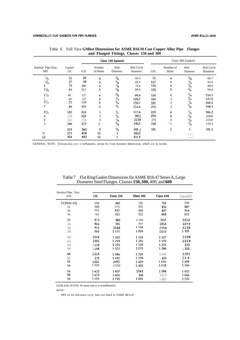
Tabie 6 Full Face GMket Dimensions for ASME B16.M Cast Copper Alloy Pipe Flanges
and Flanged Fittings, Classes 150 and 300
Class 300 Gaskets
lominal Pipe Size, Gasket f4 umber Hole Bolt Circle
NPS I.D. O.D. of Holes Diameter Diameter O.D.
Number of Hole Bolt Circle
Holes Diameter Diameter
2j 89 27 98 33 doe
48 127
2 60 152
102 216 8
iI4 229 8
I41 I54 8
6 8
219 3A3
TO 2?3 406
924 483
60.3
69.9
79.¥
88.9
90j
2159
24L3
298.j
3610
43t.8
95
8
8
8
279 8
\ 2
]2
66.7
82.6
88.9
98.4
2000
2350
2 69.9
330.2
GENERAL NOTE. D im ens ions a re i n millimeters, escept fo r h ote diameter dimens ions, which a re in in ches.
Table 7 Flat Ring Gasket Dimensions for ASME B16.47 Series A, Large Diameter Steel Flanges. Classes 150, 300, 400, and 600
l4ominal Pipe Size,
f4 PS
Class6OO
2 2 [Note (2)]
660 705 ?02 2 6 660
835 832 28
899 897 30 762 883 953 946
9A0 2 006 :oo3 1012
34 991 057 l0S4 l0?3
36 1048
rna 1130
38
I 0/3
40 1016 ]156
42 1061 1219
44 i i18 210
46 I i68 I 2?3 i 32Z
1 219 1346 1391 d0 2?0 403 I 4 8
1321 Jd92
1559
1543
594 1619 60
1 6B3 G£f4£ kAL f4 OTE: Di mens ions a re in millimeters.
NOTE:
NPS 22 for refe rence o n ly. Size n ot listed in ASME BE 6.47.
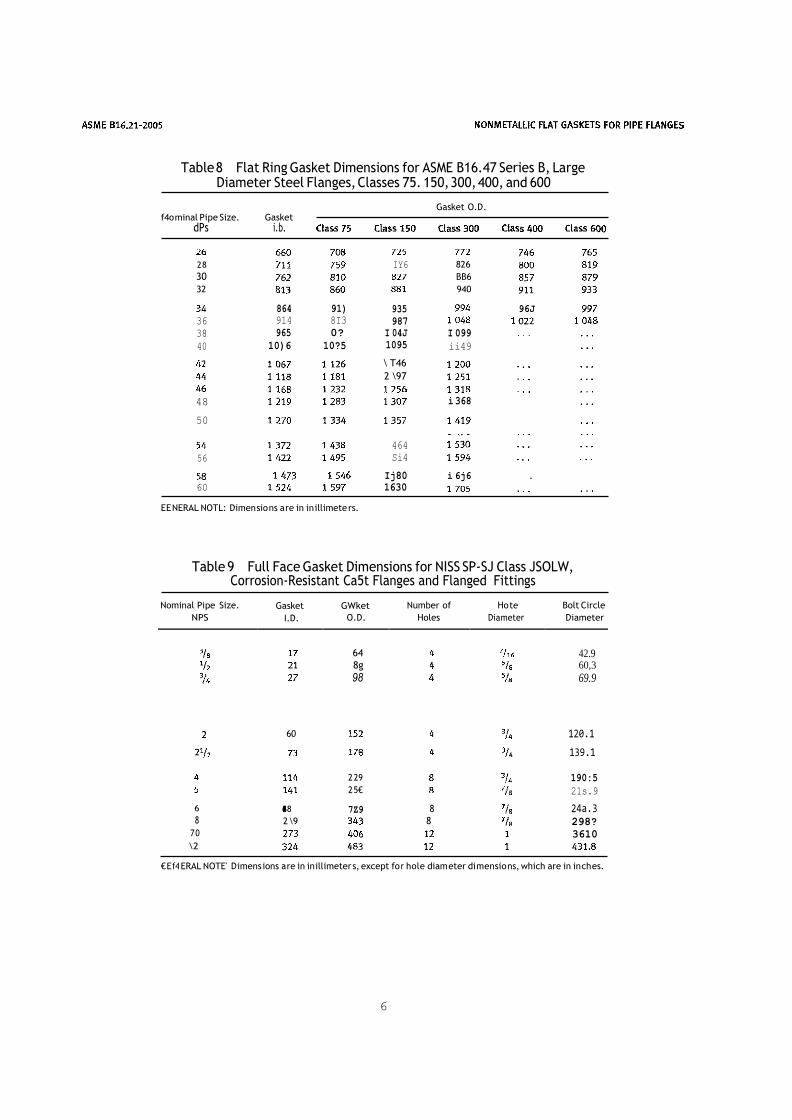
Table 8 Flat Ring Gasket Dimensions for ASME B16.47 Series B, Large Diameter Steel Flanges, Classes 75. 150, 300, 400, and 600
Gasket O.D. f4o minal Pipe Size. Gasket
2 8
30
32
864 91)
36 914 8I3
38 965 0?
40 10)6 10?5
48
50
IY6
935
987 I 04J
1095
\ T46
2 \97
826
BB6
940
I 099
ii49
i 368
96J
464
56 Si4
Ij80
i 6j6 .
EE NERAL NOTL: Dimen sio ns a re in in illimete rs.
Table 9 Full Face Gasket Dimensions for NISS SP-SJ Class JSOLW,
Corrosion-Resistant Ca5t Flanges and Flanged Fittings
60
6 I68
8 2 \9
7 0
\2
2 29
2 5€
7Z9 8 8
120.1
139.1
190:5
21s.9
24a.3 298?
3610
€ E f4 ERAL NOTE' D imens ions a re in in illimeter s, except fo r hole diam eter di mensio ns, which are in in ch es.
6
60 1630
dPs i.b.
Nominal Pipe Size.
NPS
Gasket
I.D.
GWket
O.D.
Number of
Holes
Ho te
Diameter
Bolt Circle
Diameter
64
42.9
8g 60,3
98 69.9
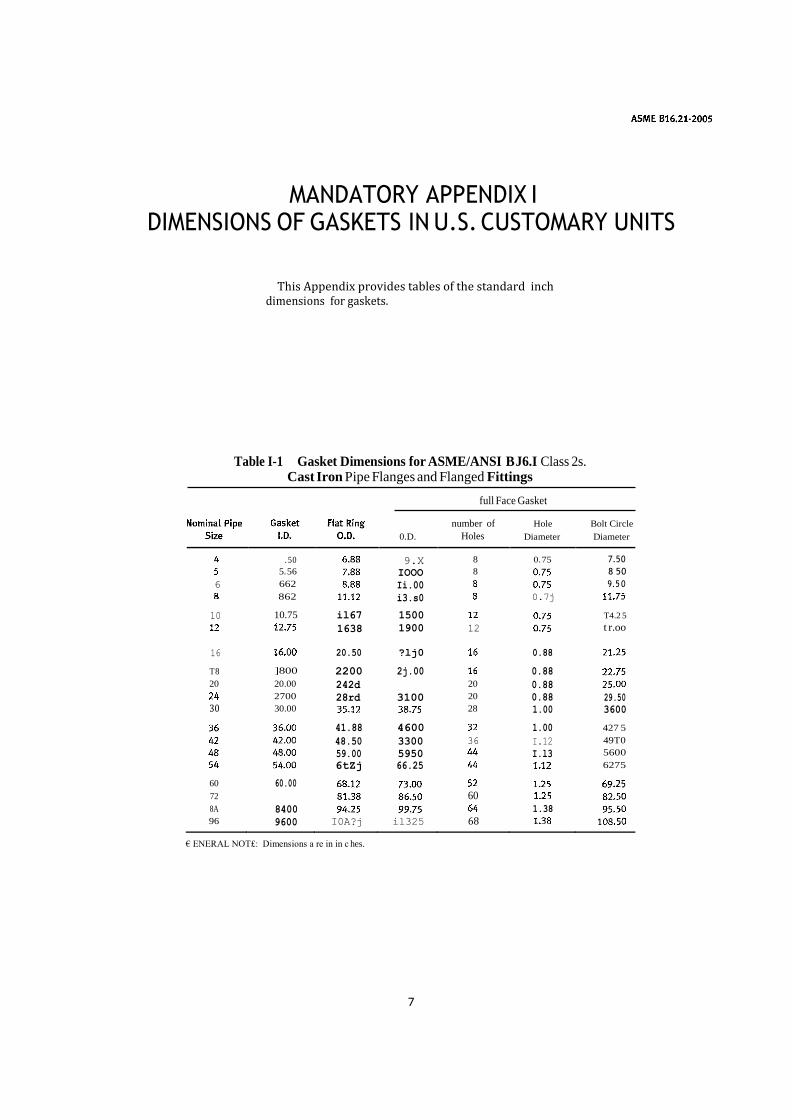
MANDATORY APPENDIX I DIMENSIONS OF GASKETS IN U.S. CUSTOMARY UNITS
This Appendix provides tables of the standard inch dimensions for gaskets.
Table I-1 Gasket Dimensions for ASME/ANSI B J6.I Class 2s.
Cast Iron Pipe Flanges and Flanged Fittings
full Face Gasket
0.D.
number of
Holes
Hole
Diameter
Bolt Circle
Diameter
. 50 9.X 8 0. 75 7.5 0
5. 56 IOOO 8 8 5 0
6 662 Ii.00
9.5 0
862 i3.s0
0.7j
10 10.75 il67 1500
T4.2 5
1638 1900 12 t r.oo
16
20.50 ?lj0
0.88
T 8 ]800 2200 2j.00
0.88 20 20.00 242d 20 0.88
2700 28rd 3100 20 0.88 29.50 30 30.00 28 1.00 3600
41.88 4600
1.00 427 5
48.50 3300 36 I.12 49T0
59.00 5950
I.l3 5600
6tZj 66.25
6275
60 60.00
72 60
8A 8400
1.38 96 9600 I0A?j il325 68
€ ENERAL NOT£: Dimensions a re in in c hes.
7
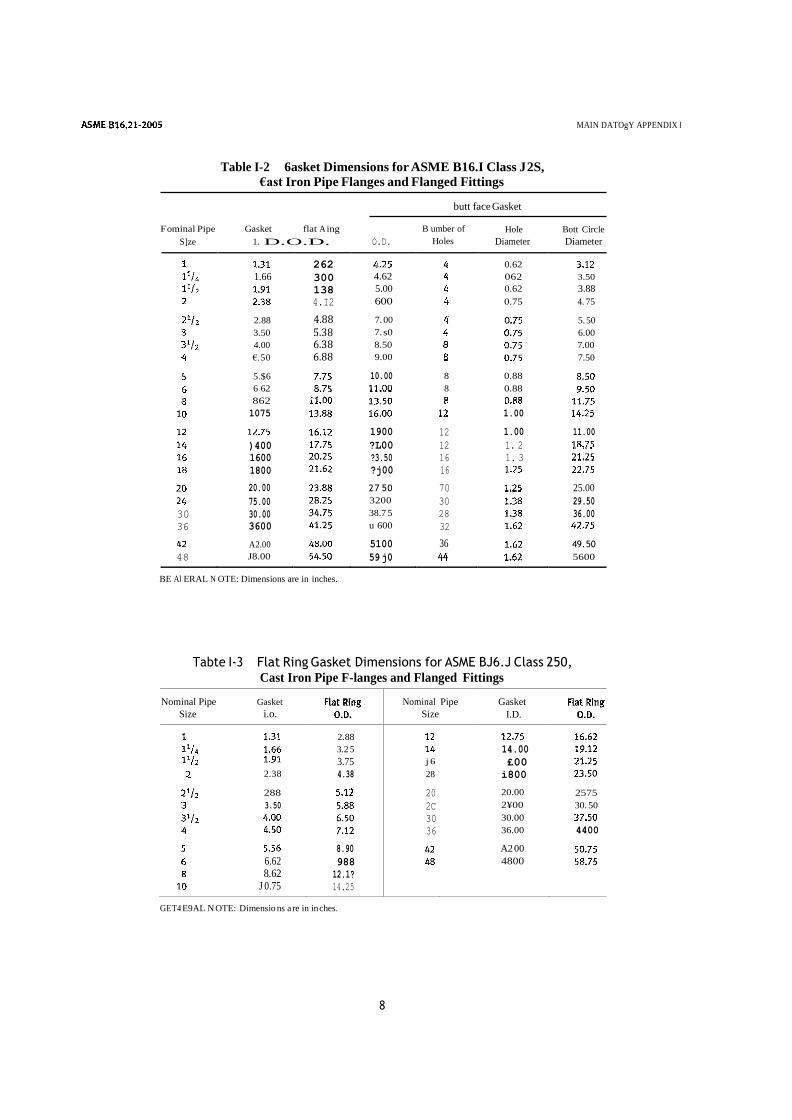
Table I-2 6asket Dimensions for ASME B16.I Class J 2S, €ast Iron Pipe Flanges and Flanged Fittings
MAIN DATOgY APPENDIX I
butt face Gasket
F ominal Pipe Gasket flat A ing
S]ze 1. D.O.D.
BE Al ERAL N OTE: Dimensions are in inches.
O.D.
B umber of
Holes
Hole Bott Circle
Diameter Diameter
Tabte I-3 Flat Ring Gasket Dimensions for ASME BJ6.J Class 250, Cast Iron Pipe F-langes and Flanged Fittings
Nominal Pipe Gasket
Size i.o.
Nominal
Size
Pipe Gasket
I.D.
2.88
3.2 5
14.00
3.75 j 6 £00
2.38 4.38 28 i800
288
20 20.00 2575
3.50 2C 2¥00 30. 50
30 30.00
36 36.00 4400
8.90 A2 00 6.62 988 4800 8.62 12.1?
J 0.75 14.25 GET4 E9AL N OTE: Dimensio ns a re in in ches.
8
262
0.62
1.66 300 4.62
062 3.50
138 5.00
0.62 3.88
4.I2 600
0.75 4. 75
2.88 4.88 7. 00
5. 50
3.50 5.38 7. s0
6.00
4.00 6.38 8.50
7.00
€. 5 0 6.88 9.00
7.50
5.$6 10.00 8 0.88 6 62
8 0.88 862
1075
1.00
1900 12 1.00 11.00
)400 ?L00 12 1. 2
1600 ?3.50 16 1. 3
1800 ?j00 16
20.00 2 7 5 0 70
25.00
75.00 3200 30 29.50
30 30.00 38.7 5 28 36.00
36 3600 u 600 32
A2.00 5100 36 49. 50
48 J8.00 59 j0
5600
MANDATORY APPENDIX I
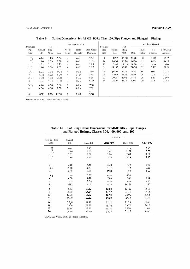
Table I-4 Gasket Dimensions for ASME BJ6.s Class 150, Pipe Flanges and Flanged Fittings
t4 omina t
Pipe
Size
GasLet
l. D.
Flat
lting
O.D.
O.D.
Nu II
No. of
Holes
face G asket
Ho te
Diameter
Boft Circte
D iameter
No in ina I
Pipe
Size
basket
I.D.
Flat
Ring
O.D.
O.D.
bull
No. of
Holes
face Gasket
Ho le
Diameter
Bolt Circle
Diameter
L38 8 862 1100 Ilj0 8 0.88 1I./F
2.7& i0 10Jd 1138 i600 i2 LOO 1425
li3 12 3Jd i6.13 1900 i2 COO iA0O
lü0 14 14.00 WIJS 2LO0 12 112 I8,I5
I'/, L91 138 900 4 062 388 j 6 j 600 202 5 23 50 f 6 1H2 2 L25
? j.38 AI2 600 4 0.Zj ?7ê j 6 T 800 2 L62 2500 26 L2 5 2 275
2’/, 188 488 COO 4 0J5 550 20 2000 2388 27. 50 20 1.25 2 500
3 3.50 ï38 750 4 075 6 0O 2 4 2k00 282 5 3200 20 L3B 2 750
700 750
6 662 8J5 ]*00 8 0.88
€i E N E kAL f4 OTE: D i m en sions a re in in ches.
Table I-s Flat Ring Gasket Dimensions for MME B16.5 Pipe Flanges
and Flanged fittings, Classes 300, 400, 600, and f00
Gasket O.D. h om ina I Pipe
Size
5askel
T.D.
€tass 300
€lass 600
084
2. \ 2
1.06 2. 62 2. 62 2.62
\.3\ 2.88 2.88
1.66 3.2 5 3.25
2 138
438
2'// 188
9.12
6.90 3 3.j0 5.B8 F88
662
4.00 6.50 6.38 6.38
7.00 7.62
5.56 8.50 8.38 9.so 9. 75
6 662
9.75 10.50 j \ .38
8.62 i2.62
]0 70. 75
12.75 1800 z962
2 0.50
I6g0 2Id2
22.62
1800 23.38 2AU 2 2s.t2
30.00 BS.50 2688 27. CO
24.00 30.50 3029
3100
GENERAL NOTE: Di men sio ns a re i n in c hes.
ASME BE 6.2J -2005 MAIN DATORY APPENDIX I
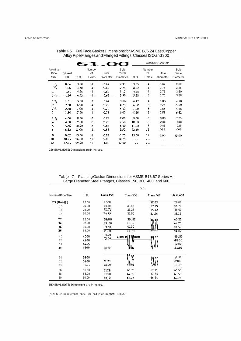
Table I-6 Futl Face Gasket Dimensions for ASME BJ6.24 Cast Copper Alloy Pipe Flanges and Flanged Fittings. Classes ISO and 300
Class 300 Gas/‹ets
Atom inal
Pipe
gasket
Num ber
of
Bolt
Note Circle
Number
of
Hole
Bolt
circle
Size I.D. 0.D. Holes Diam eter Diameter O.D. Holes Diameter Diameter
0.62 2.62
0.75 3.25
0.75 3.50
0.75 3.88
GZt4Ek/\L NOTE: Dimensio ns are in in clues.
Tab{e I-7 Flat Iting Gaskat Dimensions for ASME B16.67 Series A, Large Diameter Steel Ftanges, Classes 150, 300, 400, and 600
O.D.
thorn inal Pipe Size
23 {Noe Q ]
j6
78
3o
40
42
*4
50
52
5C
I.D.
2 2.00
26.00
28.00
30.00
32.00
3¥.00
3 6.00
3 8.00
4000
4200
4600
5B00
5200
2 600
3 0.50
BJ.7¢
3A00
39.00
Class 300
32.88
35.38
37.50
39.62
#I.62
4100
S1.j0
2 8.88
3 A. 72
36.00
38.2 5
49.50
4800
5126
jY.00
d900
6i.2d
€i ENER/\L NOTE: Dimensions a re in inches.
(7) NPS 22 fo r reference on ty. Size no Ilis fed in ASME B36.A7.
56
58
60
5 6. 00
5 8.00
60.00
6129
6550
6Z]0
6T. 75
63.7 s
66.2 s
0.88 7.? 5
0.88 788
0.88 925
088 063
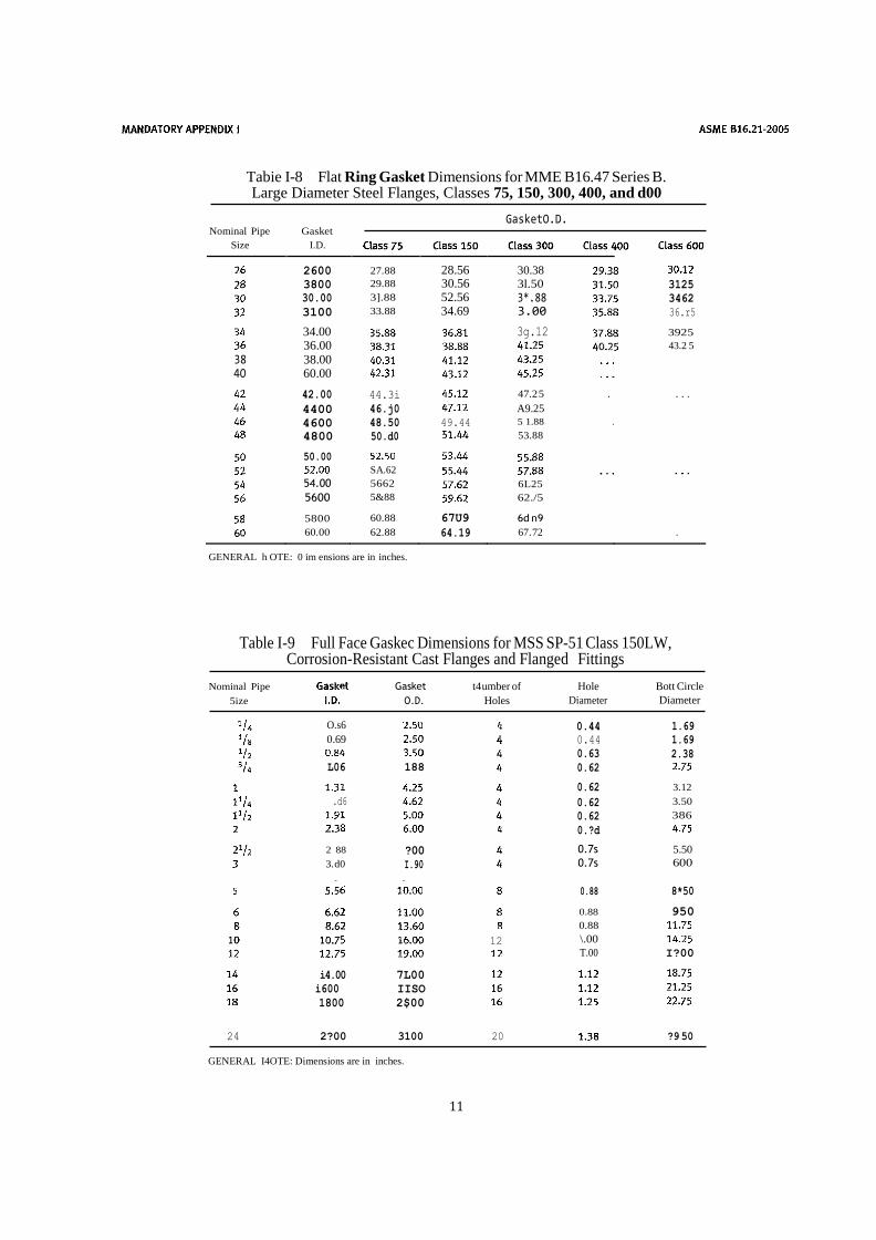
Tabie I-8 Flat Ring Gasket Dimensions for MME B16.47 Series B. Large Diameter Steel Flanges, Classes 75, 150, 300, 400, and d00
Nominal Pipe
Gasket
GasketO.D.
Size I.D.
2600 27.88 28.56 30.38
3800 29.88 30.56 3l.50 3125
30.00 3].88 52.56 3*.88 3462
3100 33.88 34.69 3.00 36.r5
34.00 3g.12 3925
36.00
43.2 5
38 38.00
4O 60.00
42.00 44.3i
47.2 5 . . . .
4400 46.j0
A9.25
4600 48.50 49.44 5 1.88 .
4800 50.d0
53.88 50.00
SA.62 54.00 5662 6L25 5600 5&88 62./5 5800 60.88 67U9 6d n9 60.00 62.88 64.19 67. 72 .
GENERAL h OTE: 0 im ensions are in inches.
Table I-9 Full Face Gaskec Dimensions for MSS SP-51 Class 150LW, Corrosion-Resistant Cast Flanges and Flanged Fittings
Nominal Pipe
5ize
O.s6
0.69
L06
.d6
2 88
3. d0
Gasket
O.D.
188
?00
I.90
t4 umber of
Holes
Hole
Diameter
0.44
0.44
0.63
0.62
0.62
0.62
0.62
0.?d
0.7s
0.7s
Bott Circle
Diameter
1.69
1.69
2.38
3.12
3.50
386
5.50
600
12
i4.00 7L00
i600 IISO
1800 2$00
24 2?00 3100 20
0.88
0.88
0.88
\.00
T.00
8*50
950
I?00
?9 50
GENERAL I4OTE: Dimensions are in inches.
11
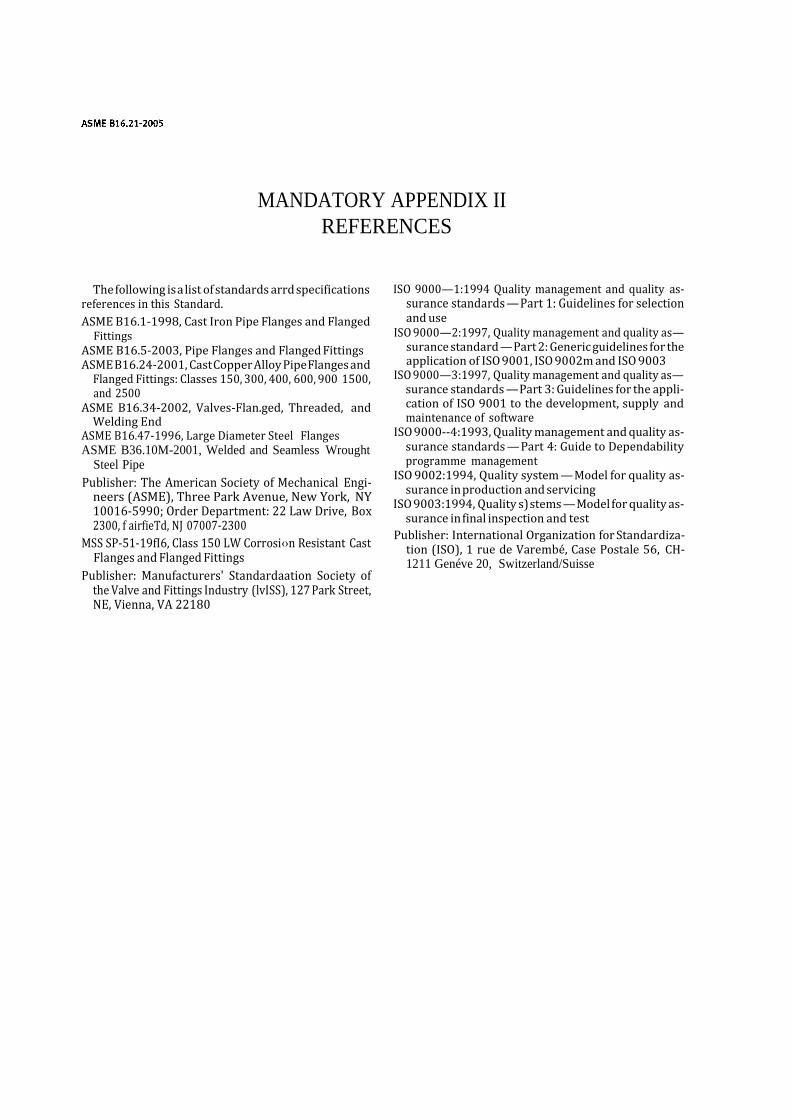
MANDATORY APPENDIX II
REFERENCES
The following is a list of standards arrd specifications references in this Standard.
ASME B16.1-1998, Cast Iron Pipe Flanges and Flanged Fittings
ASME B16.5-2003, Pipe Flanges and Flanged Fittings ASME B16.24-2001, Cast Copper Alloy Pipe Flanges and
Flanged Fittings: Classes 150, 300, 400, 600, 900 1500, and 2500
ASME B16.34-2002, Valves-Flan.ged, Threaded, and Welding End
ASME B16.47-1996, Large Diameter Steel Flanges ASME B36.10M-2001, Welded and Seamless Wrought
Steel Pipe
Publisher: The American Society of Mechanical Engi- neers (ASME), Three Park Avenue, New York, NY 10016-5990; Order Department: 22 Law Drive, Box 2300, f airfieTd, NJ 07007-2300
MSS SP-51-19fI6, Class 150 LW Corrosi‹›n Resistant Cast Flanges and Flanged Fittings
Publisher: Manufacturers' Standardaation Society of the Valve and Fittings Industry (lvISS), 127 Park Street, NE, Vienna, VA 22180
ISO 9000—1:1994 Quality management and quality as- surance standards — Part 1: Guidelines for selection and use
ISO 9000—2:1997, Quality management and quality as— surance standard — Part 2: Generic guidelines for the application of ISO 9001, ISO 9002m and ISO 9003
ISO 9000—3:1997, Quality management and quality as— surance standards — Part 3: Guidelines for the appli- cation of ISO 9001 to the development, supply and maintenance of software
ISO 9000--4:1993, Quality management and quality as- surance standards — Part 4: Guide to Dependability programme management
ISO 9002:1994, Quality system — Model for quality as- surance in production and servicing
ISO 9003:1994, Quality s) stems — Model for quality as- surance in final inspection and test
Publisher: International Organization for Standardiza- tion (ISO), 1 rue de Varembé, Case Postale 56, CH- 1211 Genéve 20, Switzerland/Suisse
NONMANDATORY APPENDIX A QUALITY SYSTEM PROGRAM
The products manufactured in accordance with this Standard shall be produced under a quality system pro- gram following the principles of an appropriate stan- dard from the ISO 9000 series.' A determination of the need for registration a:nd/or certification of the product manufacturer’s quality system program by rim inde- pendent organization shall be the responsibility of the manWacturer. Detailed documentabon demonstrat-ing
program compliance shall be available to the purchaser at the manufacturer’s facility. A r'ritten, summarized description of the program used by the product manu— facturer shall be available to the purchaser uyon request. The product manufacturer is defined as the entity whose name or trademark appears on the product in accor- dance with the marking or identification requirements of this Standard.
15
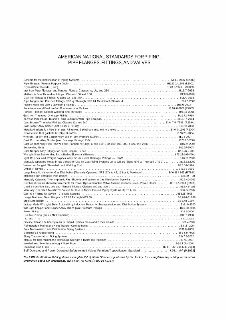
AMERICAN NATIONAL STANDARDS FOR PIPING, PIPE FI.ANGES. FITTINGS, AND VALVES
Scheme for rfie Identification of Piping Systems . . . . . . . . . . . . . . . . . . , . . . . . . . . . . . . . . . . . . . . . . . . . AT3,\- \ 996 (92002)
Pipe Threads. General Purpose (Inch) . . . . . . . . . . . . . . . . . . . . . . .. . . . . . . . . . . . . . . . . . . . . . . . . . . . . . . . . . . . . . . . BE.20.2 -1983 (k2001)
Dryseal Pipe Threads (I nch] . . .. . . . . . . . . . . . . . . . . . . . . . . . . . . .. . . . . . . . . . . . . . . . . .. . . . . . . . . . . . . . . . . . . . . , B\.20.3-1976 (92003)
last Iron Pipe Flanges and flanged Fltings: Classes is, Us, and 250 . . . .. . . . . . . ' .. ' . . . . . . . . . . . . . . . . . . . . . . . . . . . . . . .. B16.7-2998
Matleab Ie 7 ron Threa d ed fittings • Classes 150 and 3 00 . . . . . . . . . . . . . .. . . . . . . . . . . . . . . . . . . . . . . . . . . . . . . . . . . . . . . . . . . . . BE 6.3-1998
Gray Iron Th read ed Fittings: Classes 12 an d 2 TO . . . . . . . . . . . . . . . . . .. . . . . . . . . . . . . . . . . . . . . . . . . . . . . . . . . . . . . . . . . . . . . B \6.A 1998
Pipe flanges and Plan bed Fittings NPS /y Thro ugh NPS 24 Metric/ Inch Stan da rd . . . . . . . . . . . . .. . . . . . . . . .. . . . . . . . . . . . . . . . B\ 6. 5-2003
Factory-Made Wro ughr B uttweldin g Fittings .. . . .. . . . . . .. . . .. . . . . . . . . . . . . . . . . . . . . . . . . . . .. . . . . . . . . . . . . . . . . . .. . . . . BI6.9 2003
Face-to-face and En d -to-End D imensio ns of Va toes . . . . . . . . . . . . . . . . . . . . . . . . . . . . . . . . . . . . . . . . . . . . . . . . . . . . . B 16.t0-2000 (R2003]
Forged Fittings Socket-Welding and Threaded . . . . . . . . . .. . . . . . . . . . . . . .. . . . . . . .. . . . . . . . . . . . . . . . . . . ... . .. . . . . . . B \6.11 2001
€ast Iron Threaded Drainage Fittinis . . . . . . . . . . . . . . . . . . . . . . . . . . . . . . . . . . . . . . . . . . . . . . . , . . , . . . . . . . . . .. . . . . . , .. , . B 16.72-7 998
be rro us Pipe PIugs, Bushinis, an d Lockn uts With Pipe Th re ad s . . . . . . . . . . . . . . . . . . . . . . . . . . . . . . . . . . . . . . . . . . . . . . . . . . . B 16.Th-299d
¢a st Bronze Th readed Fittings: Classes 12s and 2s0 . . . . . . . . . . . . . . . . . . . . . . . . . . . . . . . . . . . . . . . . . . . . . , . . , , . B) 6. 7 5 -7985 (R299A)
Cast Copper Alloy Solder {oint Pressure Fit1:ings . . . . . . . . . . . . . . . . . . . . . . . . . . . . . . . . . . . . . . . . . . . . . . . . . . . . . . . . . . . . . . . B16.78 2003
Metallix 6 askets fo r Pipe 1- an ges: R ing-joint, 5 p iral-Wo and, and }a c keted , . , . . . . . . . . . . . . . . . . . , . . , . . . . . . . . . . .. . B) 6.i0-1998 (R2004]
Non metallic D- at gaskets for Ptpe Lt- an Yes . . . ... . . , . . . . . . . . . . . . . . . . . . . . . . . . . . . . . . . . . . . . . . . .. . . . . . . . . . . . . . . . . . . B 7 6.2 7 -200a
Wro ught Top pe r and Copper A\ I oy Solder ] oint Pressure Et1:ings , . . . . . . . . . . . . . . . . . . . . . , . . . . . . . . . . . . . . . . . . . . , . . . . . , BI6.2 2 2007
Cast Co p per Alloy So lder ] oint Drainage Pittings' DM . . . . . . . . . . . .. .. . . .. , . . . . . . . . . . . . . . . . . .. . . . . . . . . .. . . . . . . . . .. B 76.2 3-2002
Cast Co pper Alloy Pipe Plan Yes and 7lan8ed 7it Kings: C/ ass 7 50 3 00, c00, 600, 900. T 500, an d 2 500 .. . .. . . . . . . . . . . . . . . . . . B16.24 200a
Buttwelding Ends . . . . . . . . . . . , . . . . . . . . . . . . . . . . . . . . . . . . . . . . . . . . . . . .. . . . . . . . . . . . . . , . . , . . . . . . . . . . . . . . . . . . . . . B \6.25-2003
Cast No pper Alloy Fitt]ngs for flared Copper Tu bes . . . . . . . . . . , . .. . . . . . . . . . . . . . .. . . . . . . . . . . . . . . . . . . .. . . .. . . . . . . . . B 16.26 2 9 88
Wro ught Sreet Buttwe Iding Bho rt Radius Elbows and Returns . . . . . . . ... . . . . . . . . . . . . . , . . , . . . . . . . . . . . . . . . . . , . . . . . , . . B 76. 28-1994 Wro
ught Co p pe r an d Proight £o ppe r Alloy So Ide r joint Drainage Pittings — DWV . . . . . . . . . . . . . . , . . . . . . . . . . . . . . . . . ... . B 16.29 200a
Manual]y Operated Metat] ir has Valves for Use T n Gas Piping Systems up to 725 ps (Sizes NPS // Thro ugfi UPS 2) . .... . . .. , B16.33 2002
Valves — flanged, Threaded, and Welding End . . .. .... . . . . . . . . . . . . . . . .. . . . . . . . . . . . . . .. . . . .. . . . ... . . . . . . . . . . . . . BE 6.34-1996
Orifice F-an Yes . . . . . . . . . . . . . , . . . . . . . . . , . . , . . . . . . . . . . . . . . . , . . . . . . , . . . . . . . . . . , . , . . . . . . . . . . . . . . . . . . , , . . . . .. B \6.3 6-1996
Large Meta llic Valves for € as Distribution [Manually Operated. NPS 2'/z to \ 2, \2 ii ps ig Maximum] . . . . . . . . . . . . . . . . . B \6.38 \ 985 (R T99h)
Malleable iron Threaded Pipe Unions . . . . . . . . . , . . . . . . . . . . . . . . . . . . . . .. , . . . . . . . . . . . . , . . , . . , . . . . , . . . . . . . . . . . . . B)6.39- 98
Manually Operated Therm o pla stic €as Sh utoffs and \/a Ives in ¢ as D istribution Syste ins . .. . . . . . . . . .. .. . .. . . . . . . . . . . . . . . . B 2 6.40-i 002
Fun ction at Qualific a two n Require ments for Power O p e rated Active Valve Assemb lies fo r f4 uclea r Powe r Plants . . . . . . . .. . BE 6.47 -7983 [Rl989]
D u ctil e Iron Pipe Sta o ges and Flanged Filtin gs, Classes \ s0 and 300 . .. . . .. .... . . . . . . . . . . . . . . . . . . . .. . . . . . . . . . . . . . .. . BE 6.42- gp8
Manually Ope ra ted Metallic 'as Valves for lJ se in Above Eround Piping S yste ins lJp To I› psi . . . . . . . . . . .. . . . . . . . . . . . . . . . . . BE 6.h4-2002
Case I ro n F-ittings for Sovent D rainage Systems . . . . . . . . . . ... . . . . . . . . . . . . . . . . . . .. . . . . . . . . . . . . .. .. . . . .. . . . . . . . . . BE 6.J5 -7998
La rge Diameter Stee I flanges (NPS 26 Through NPS 60] . . . . . . . . . . . . . . . . . . . . . . . . . . . . , . . . . . . . . . . . . . . . . . , . . . . . . . . . BE 6.h7-2 996
Steel Line BIan M . . . . . . . . . . . . . . .. . . . . . . . . . . . . . . . . . . . . . . . . . . . . . . . . . . . . . . . . . . . . . .. . . . . . . . . . . . . . . . . . . . . . . BE 6.h8 1997
factory Made Wro ught Stee I B uttweldin g Induction Bends for Transportation and Distribution Systems . . . . . . . . . . . . . . . . . . . . . B \6.h9-2000
Wro ught €op pe r and Co pper Alloy Braze ] oint Pressure 7iltin gs . . . . . . . . . . . . . . . .. . . . . . . . . . . . . . . . . . . .. . . .. . . . . . . . . . . B\ 6.50-200a
Power Piping . . . . . . . . . . . . . . . . . . . . . . . . . . . . . . . . . . . . . . . . . . . . . . . . . . . . . . . . . . . . , . . . . . . . . . . . . . . . . . . . . . . , . . . . . . . B3 7.2-200d
Fu el Seas Pi p ing (not an ANSI standa rd) . . . . . . . . . . . . . . . . . . . . . . . . . .. . .. . . . . . . . . . . . . . . . . . . . . . . . . . . . . . . . . . . . . . B3f . 2 296B
f0 e6£ i \ 0 . . . . . . . . . . . . . . . . › . . . . . . . . . . . . . . . . . . . . . . . . . . . . . . . . . . . . . . . . . . . . . . . . . . . . . . , . . . . . . . . . . . . . . . . . . B3 7.3-2002
Pipeline Transp o rta tion Systems fo r Liquid Hydroca rbo ns and O Iher Liquids . .. . . . . . . . . . . . . . .. . . . . . . . . . . . . . . , . . . . . . . . . B31.4-2002
Refrigeratio n Piping an d H eat Transfer Com po nents . . . .. . . . . . . . . . . . . . . .. . . . . . . . . . . . . . . . . . . . . . . .. . . . . . . . . . . . . . . . . B3 I.5 200)
€›as Transm issio n and Distribution Piping System s . . . . . . . . . . . . . . . . . . , . . . . . . . . . . . . . . , , . . . . . . . . . . . . . . . . . . . . . . , . , . . B 31.8 -2003
B uitding Se rvices Piping . . . . . . . . . . . . . . . . . . . . . . . . . . . . . . . . . . . . . . .. . . . . . . . . . . . . . . . . . . . . . . . . . . .. . . . . . . . . . . . . . . B 3 T.9- \996
Slurry Transp o rtat] on Piping Systems . . . . . . . . . . . . . . . .. . . . . . . . . . . . . . . . . . . . . . . . . . . . . . . . . . . . . . . , , . . . . . . . . B3 \ . \ 2 -2002
Manual for Dete rmin]n$ th e Remainin$ Stren gth o ICorro ded Pipelines . . . . . . . . . . . . . . . . . . . . . . . . . . . . . . . . . . . . . . . . . . . . . . . 83 7 G -2997
Welded an d Seamless Wrought Steel Pi pe . . . , . . . . . . . . . . . . . . .. . . . , . . . . . . . . . . . . . . . . . . . . . . . . . . . . . . . . . . . . . . . . . . B3 6.T 0M-2004
Stain less Stee I Pipe . . . . . . . . .. . . . . . . . , . . . . . . . . . . . . . . . . . . . . . . . . . . . . . . . . . . . . . . . . . . . . . . . . .. . . . . . . , . B3 6. T9M• 798 5 (R 2 9g4]
Self-Operated and Power-Operated Safety-related Valves FunrtionaT specification Standard .. . . . . .. . . . . . . . . . . . . .. kJ/8. I -I9 /f (P:1992]