Embed Size (px)
Citation preview
2
FOR FLAGOOD SERVICING PRACTICES
MMABLE REFRIGERANTS:A QUICK GUIDE
Updated Version

2
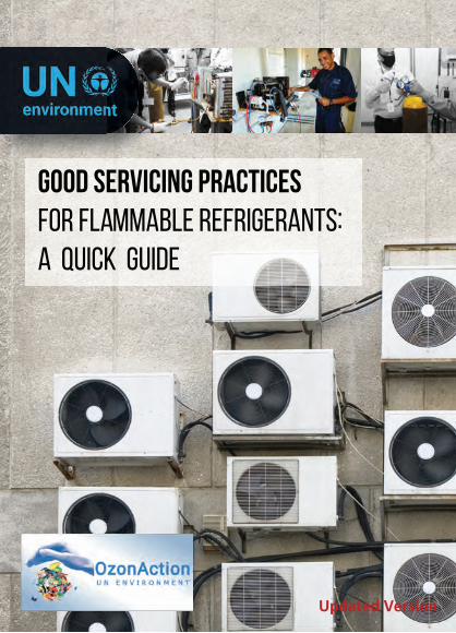
COPYRIGHT © UN ENVIRONMENT, 2016
This publication may be reproduced in whole or in part andin any form for educational or non-profit purposes withoutspecial permission from the copyright holder, providedacknowledgement of the source is made. UN Environment,would appreciate receiving a copy of any publication thatuses this publication as a source .
No use of this publication may be made for resale or forany other commercial purpose whatsoever without priorpermission in writing from the UN Environment .
3
DISCLAIMER
The designations employed and the presentation of thematerial in this publication do not imply the expression ofany opinion whatsoever on the part of the United NationsEnvironment Programme concerning the legal status of any country, territory, city or area or of its authorities, orconcerning delimitation of its frontiers or boundaries.Moreover, the views expressed do not necessarily representthe decision or the stated policy of the United NationsEnvironment Programme, nor does citing of trade namesor commercial processes constitute endorsement .
This guide book was jointly produced by UN Environment,Economy Division, OzonAction and the Pacific IslandsCountries (PIC) Network of National Ozone Officers andas a recommendation following on the UN EnvironmentMontreal Protocol Compliance Assistance Programme,joint workshop for ozone officers and refrigeration andair-conditioning technicians (RAC) for the PIC.
The project was supervised byDr. Shamila Nair-Bedouelle, Head, UN Environment OzonAction
This project was managed byArtie Dubrie, Regional Network Coordinator, Pacific IslandsCountries, UN Environment OzonActionPipat Poopeerasupong, HPMP Officer, UN EnvironmentOzonActionChaad Somma, Communication Assistant, UN EnvironmentOzonAction
ACKNOWLEDGEMENTS
4
UN Environment OzonAction gratefully acknowledges the
assistance of the following reviewers:
Manuel P. Azucena, PhilippinesEzra Clark, Capacity Building Manager, UN EnvironmentOzonActionJames Curlin, Network & Policy Manager, UN EnvironmentOzonAction
Bertoldo Esteban Jr, Federated States of Micronesia
Shaofeng Hu, Regional Network Coordinator, South-East
Asia, UN Environment OzonAction
Anshu Kumar, India
Tingxun Li, China
Siow Wei Lim, Malaysia
Michael Moller, Australia
Fiji Refrigeration and Air-conditioning Association
National Ozone Officers of the Pacific Island Countries
UN Economic Social Commission for Asia and the Pacific,
Facilities Management Unit
ACKNOWLEDGEMENTS
5
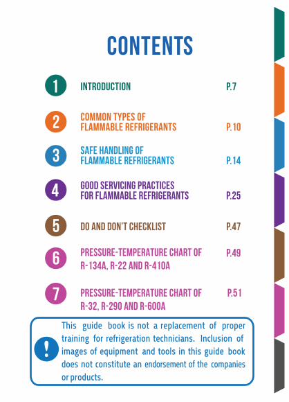
INTRODUCTION P.7
COMMON TYPES OFFLAMMABLE REFRIGERANTS P.10
SAFE HANDLING OFFLAMMABLE REFRIGERANTS P.14
DO AND DON’T CHECKLIST P.47
PRESSURE-TEMPERATURE CHART OFR-134A, R-22 AND R-410A
Pressure-Temperature Chart of P.51R-32, R-290 and R-600a
GOOD SERVICING PRACTICESFOR FLAMMABLE REFRIGERANTS P.25
CONTENTS
1
2
3
4
5
6
7
P.49
This guide book is not a replacement of proper training for refrigeration technicians. Inclusion of images of equipment and tools in this guide book does not constitute an endorsement of the companiesor products.
©SHUTTERSTOCK
1CHAPTER 1
INTRODUCTION
BACKGROUND
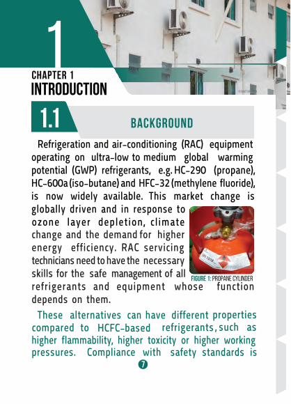
FIGURE 1:
PROPANE CYLINDER
@ P.POOPEERASUPONG
7
These alternatives can have different properties
compared to HCFC-based refrigerants , such as
higher f lammability, higher toxicity or higher working pressures. Compliance with safety standards is
Refrigeration and air-conditioning (RAC) equipment operating on ultra-low to medium global warming potential (GWP) refrigerants, e.g. HC-290 (propane), HC-600a (iso-butane) and HFC-32 (methylene f luoride), is now widely available. This market change is globally driven and in response to ozone layer depletion, climate
change and the demand for higherenergy efficiency. RAC servicing technicians need to have the necessary skills for the safe management of all refrigerants and equipment whose function depends on them.
8
extremely important for RAC servicing technicians. RAC servicing technicians must have updatedknowledge about good practices for handling these alternative refrigerants. Good servicing practices have also been recognised as the best approach towards supporting nationaI obligations for the protection of the ozone layer.
1.2 OBJECTIVES OF THIS GUIDE BOOK
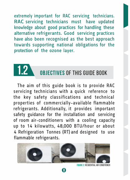
FIGURE 2: RESIDENTIAL AIR-CONDITIONER©SHUTTERSTOCK
The aim of this guide book is to provide RAC servicing technicians with a quick reference to the key safety classif ications and technical properties of commercially-available f lammable refrigerants. Additionally, it provides important safety guidance for the installation and servicing of room air-conditioners with a cooling capacity up to 14 kilowatts, 48,000 BTU/hour or about 4 Refrigeration Tonnes (RT) and designed to use f lammable refrigerants.
9
All f lammable refrigerants must be handled withprecautions and in accordance with national regulations, operation manuals and/or safety standards. Manufacturers’ refrigerant charge limits must always be complied with when servicing.
2CHAPTER 2
COMMON TYPESOF FLAMMABLE REFRIGERANTS
2.1 USE OF REFRIGERANTS IN RAC EQUIPMENT
TABLE1
HIGH GWP NON-ODSHCFC
DOMESTIC REFRIGERATOR
STAND-ALONE COMMERCIAL
REFRIGERATOR
room AIR-CONDITIONER
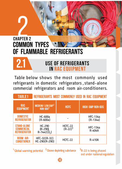
HC-600a( R-600a ) ( R-134a )
RACEQUIPMENT
HFC-134a-
HC-290 (R-290),
R-744 ( CO2 )
HCFC-22( R-22 ) HFC-134a
R-404A
HFC-32 ( R-32 )HC-290 ( R-290 ) HCFC-22 R-410A
MEDIUM/ LOW GWP1
NON-ODS2
REFRIGERANTS MOST COMMONLY USED IN RAC EQUIPMENT
3
R-22 is being phased out under national regulation
1 Global warming potential 2 Ozone depleting substance
©SHUTTERSTOCK
810
T able below shows the most commonly used refrigerants in domestic refrigerators , stand-alone commercial and room air-conditioners .refrigerators
3
11
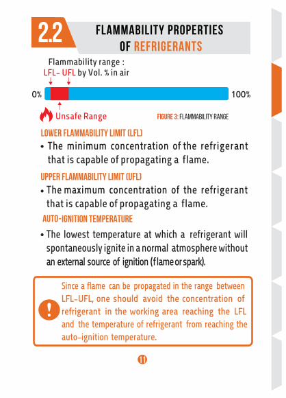
2. 2
Flammability Properties of Refrigerants
Flammability range :LFL- UFL by Vol. % in air
Unsafe Range
100%0%
FIGURE 3: FLAMMABILITY RANGE
LOWER FLAMMABILITY LIMIT (LFL) •
UPPER FLAMMABILITY LIMIT (UFL) •
AUTO-IGNITION TEMPERATURE
•
Since a f lame can be propagated in the range betweenLFL-UFL, one should avoid the concentration of refrigerant in the working area reaching the LFL and the temperature of refrigerant from reaching theauto-ignition temperature.
The minimum concentration of the refrigerant that is capable of propagating a f lame.
The maximum concentration of the refrigerant that is capable of propagating a f lame.
The lowest temperature at which a refrigerant willspontaneously ignite in a normal atmosphere without an external source of ignition ( f lame or spark ).
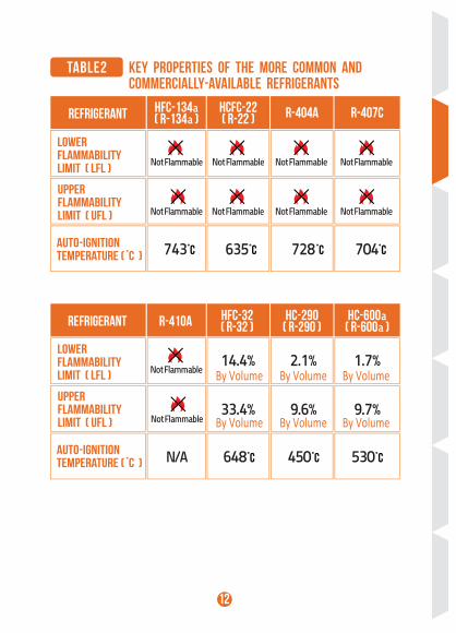
TABLE2 KEY PROPERTIES OF THE MORE COMMON ANDCOMMERCIALLY-AVAILABLE REFRIGERANTS
REFRIGERANT HFC-134a( R-134a )
HCFC-22( R-22 ) R-404A R-407C
Lower Flammability Limit ( LFL )
Upper Flammability Limit ( UFL )
Lower Flammability Limit ( LFL )
Upper Flammability Limit ( UFL )
Auto-ignition Temperature ( ํC )
Auto-ignition Temperature ( ํC )
Not Flammable Not Flammable Not Flammable
743 635 728 704
Not Flammable
Not FlammableNot FlammableNot FlammableNot Flammable
REFRIGERANT R-410A HFC-32( R-32 )
HC-290( R-290 )
HC-600a( R-600a )
Not Flammable
N/A 648 ํC 450 ํC 530 ํC
33.4% 9.6% 9.7%
14.4% 2.1% 1.7%
Not Flammable
12
ํC ํC ํC ํC
By Volume By Volume By Volume
By Volume By Volume By Volume
13
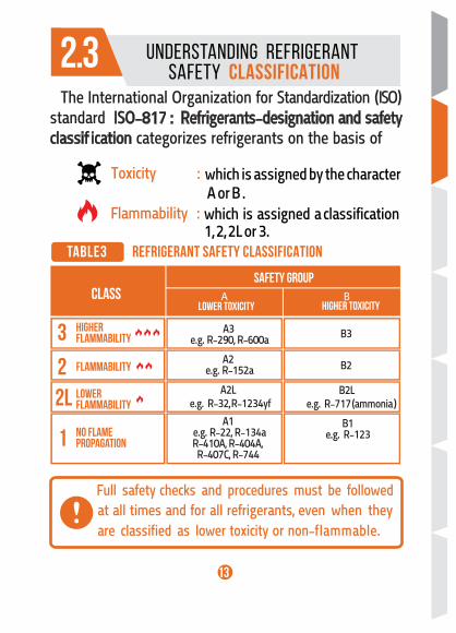
TABLE3 REFRIGERANT SAFETY CLASSIFICATION
UNDERSTANDING REFRIGERANT SAFETY CLASSIFICATION
CLASSSAFETY GROUP
HigherFlammability
Flammability
LowerFlammability
No FlamePropagation
Lower Toxicity Higher Toxicity
B1e.g. R-123
A2Le.g. R-32, R-1234yf
B2Le.g. R-717 (ammonia )
A2e.g. R-152a B2
A3e.g. R-290, R-600a B3
Flammability which is assigned a classif ication 1, 2, 2L or 3.
:
which is assigned by the character A or B .
Toxicity :
A1e.g. R-22, R-134aR-410A, R-404A,
R-407C, R-744
2.3
3
2
1
2L
Full safety checks and procedures must be followed
A B
at all times and for all refrigerants, even when theyare classif ied as lower toxicity or non-f lammable.
The International Organization for Standardization ( ISO ) standard ISO-817 : Refrigerants-designation and safety classif ication categorizes refrigerants on the basis of
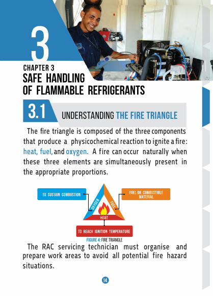
3CHAPTER 3
SAFE HANDLINGOF FLAMMABLE REFRIGERANTS
UNDERSTANDING THE FIRE TRIANGLE
OXYG
EN FUEL
HEAT
TO SUSTAIN COMBUSTION FUEL OR COMBUSTIBLEMATERIAL
FIGURE 4: FIRE TRIANGLE
TO REACH IGNITION TEMPERATURE
3.1
14
@MICHAEL MOLLER
The RAC servicing technician must organise and prepare work areas to avoid all potential f ire hazard situations.
The f ire triangle is composed of the three components that produce a physicochemical reaction to ignite a f ire:heat, fuel, and oxygen. A f ire can occur naturally whenthese three elements are simultaneously present in the appropriate proportions.
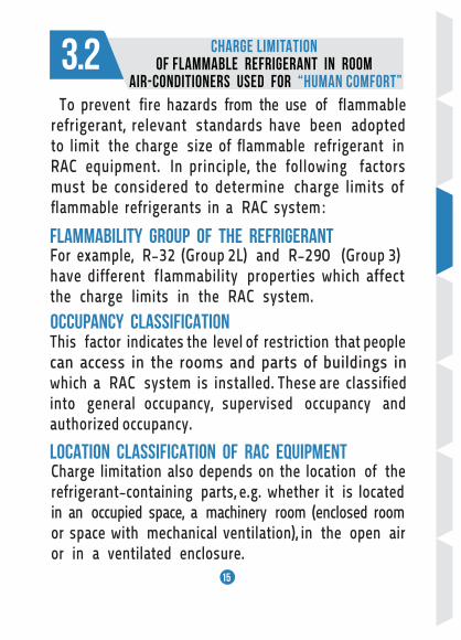
3.2 CHARGE LIMITATION OF FLAMMABLE REFRIGERANT IN ROOM
AIR-CONDITIONERS USED FOR “HUMAN COMFORT”
FLAMMABILITY GROUP OF THE REFRIGERANT
OCCUPANCY CLASSIFICATION
LOCATION CLASSIFICATION OF RAC EQUIPMENT
15
For example, R-32 (Group 2L) and R-290 (Group 3) have different f lammability properties which affect the charge limits in the RAC system.
This factor indicates the level of restriction that peoplecan access in the rooms and parts of buildings inwhich a RAC system is installed. These are classif iedinto general occupancy, supervised occupancy and authorized occupancy.
Charge limitation also depends on the location of the refrigerant-containing parts, e.g. whether it is locatedin an occupied space, a machinery room (enclosed room or space with mechanical ventilation), in the open air or in a ventilated enclosure.
To prevent f ire hazards from the use of f Iammable refrigerant, relevant standards have been adopted to limit the charge size of f lammable refrigerant in RAC equipment. In principle, the following factors must be considered to determine charge limits of f lammable refrigerants in a RAC system:
16
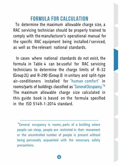
FORMULA FOR CALCULATION To determine the maximum allowable charge size, a RAC servicing technician should be properly trained tocomply with the manufacturer’s operational manual for the specif ic RAC equipment being installed / serviced, as well as the relevant national standards.
In cases where national standards do not exist, the formula in Table 4 can be useful for RAC servicing technicians to determine the charge limits of R-32 (Group 2L) and R-290 (Group 3) in unitary and split-type air-conditioners installed for ‘human comfort’ in
4General occupancy is rooms, parts of a building wherepeople can sleep, people are restricted in their movement or the uncontrolled number of people is present withoutbeing personally acquainted with the necessary safety precautions.
rooms/parts of buildings classif ied as “General Occupancy.”4 The maximum allowable charge size calculated in this guide book is based on the formula specif ied in the ISO 5149-1:2014 standard.
17
Charge limitation is the standard maximum allowable charge size of refrigerant in the respective occupancytype and location in which the RAC equipment canbe safely used. It is not the actual charge size of refrigerant in the system.
Not unitary and split-type air-conditioners,
Not installed for ‘human comfort’ in the general occupancy category,
>> please refer to relevant requirements indicated in the ISO 5149 - 1:2014 standard.
To calculate charge limit requirements of RAC systems which are:
18
TABLE4
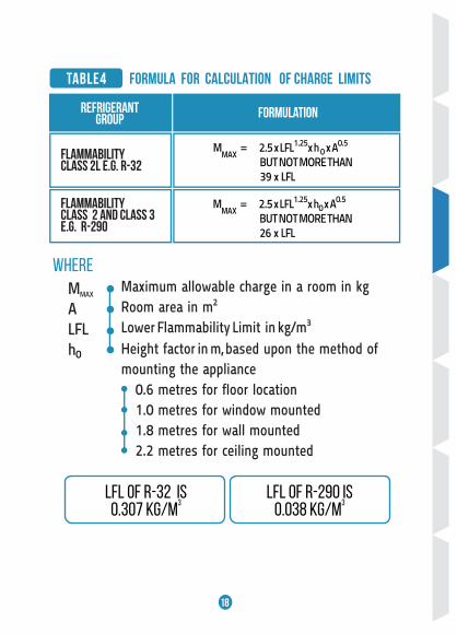
LFL of R-32 is0.307 kg/m
3LFL of R-290 is
0.038 kg/m3
MMAX
ALFL h0
FORMULA FOR CALCULATION OF CHARGE LIMITS
RefrigerantGroup Formulation
Flammability class 2L e.g. r-32
MMAX
= 2.5 x LFL1.25x h 0 x A0.5
BUT NOT MORE THAN 39 x LFL
Flammability class 2 and class 3e.g. R-290
MMAX
= 2.5 x LFL1.25x h0 x A0.5
BUT NOT MORE THAN 26 x LFL
WHEREMaximum allowable charge in a room in kgRoom area in m2
Lower Flammability Limit in kg/m3
Height factor in m, based upon the method of mounting the appliance
0.6 metres for fIoor location1.0 metres for window mounted1.8 metres for wall mounted2.2 metres for ceiling mounted
19
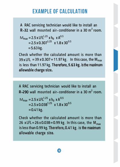
A RAC servicing technician would like to install an R-32 wall mounted air -conditioner in a 30 m room. 2
Mmax = 2.5 x LFL1.25 x h0 x A0.5
= 2.5 x 0.3071.25 x 1.8 x 300.5
= 5.63 kg. Check whether the calculated amount is more than
Check whether the calculated amount is more than
39 x LFL = 39 x 0.307 = 11.97 kg. In this case, the Mmax
is less than 11.97 kg. Therefore, 5.63 kg. is the maximum allowable charge size.
A RAC servicing technician would like to install an R-290 Mmax = 2.5 x LFL1.25 x h0 x A0.5
= 2.5 x 0.0381.25 x 1.8 x 300.5
= 0.41 kg.
EXAMPLE OF CALCULATION
26 x LFL = 26 x 0.038 = 0.99 kg. In this case, the Mmax is less than 0.99 kg. Therefore, 0.41 kg is the maximum
allowable charge size..
wall mounted air -conditioner in a 30 m room. 2

The RAC servicing technician must ensure that the actual charge size of refrigerant inthe AC system being installed/serviced does not exceed the maximum charge size.
20
TABLE5
AREA( M 2)
MMAX
FLOORLOCATION
(KG)
MMAX
WINDOWMOUNTED
(KG)
MMAX
WALL MOUNTED
(KG)
MMAX
CEILING MOUNTED
(KG)
9 1.711.03 3.09 3.77
12 1.981.19 3.56 4.35
15 2.211.33 3.98 4.87
18 2.421.45 4.36 5.33
21 2.621.57 4.71 5.76
24 2.801.68 5.04 6.16
27 2.971.78 5.34 6.53
30 3.131.88 5.63 6.88
33 3.281.97 5.91 7.22
36 3.432.06 6.17 7.54
39 3.572.14 6.42 7.85
42 3.702.22 6.66 8.15
45 3.832.30 6.90 8.43
48 3.962.37 7.12 8.71
51 4.082.45 7.34 8.98
54 4.202.52 7.56 9.24
57 4.312.59 7.76 9.49
60 4.432.66 7.97 9.74
MAXIMUM ALLOWABLE CHARGE SIZE OF R-32 IN AIR-CONDITIONING EQUIPMENT
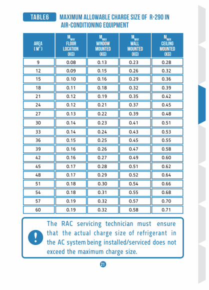
The RAC servicing technician must ensure that the actual charge size of refrigerant inthe AC system being installed/serviced does not exceed the maximum charge size.
21
AREA( M 2 )
MMAX
FLOORLOCATION
(KG)
MMAX
WINDOWMOUNTED
(KG)
MMAX
WALL MOUNTED
(KG)
MMAX
CEILING MOUNTED
(KG)
9 0.130.08 0.23 0.28
12 0.150.09 0.26 0.32
15 0.160.10 0.29 0.36
18 0.180.11 0.32 0.39
21 0.190.12 0.35 0.42
24 0.210.12 0.37 0.45
27 0.220.13 0.39 0.48
30 0.230.14 0.41 0.51
33 0.240.14 0.43 0.53
36 0.250.15 0.45 0.55
39 0.260.16 0.47 0.58
42 0.270.16 0.49 0.60
45 0.280.17 0.51 0.62
48 0.290.17 0.52 0.64
51 0.300.18 0.54 0.66
54 0.310.18 0.55 0.68
57 0.320.19 0.57 0.70
60 0.320.19 0.58 0.71
TABLE6 Maximum allowable charge size of R-290 in Air-CONDITIONING EQUIPMENT
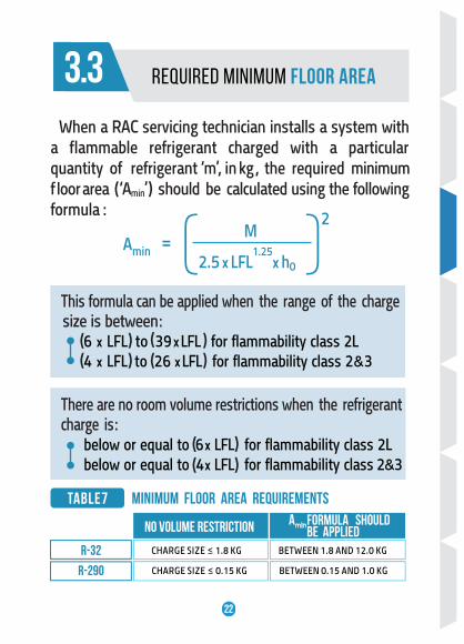
When a RAC servicing technician installs a system with a f lammable refrigerant charged with a particular quantity of refrigerant ‘m’, in kg , the required minimum f loor area ( ‘Amin’ ) should be calculated using the followingformula :
TABLE 7 MINIMUM FLOOR AREA REQUIREMENTS
Amin M
=2
2.5 x LFL1.25
x h0
There are no room volume restrictions when the refrigerant charge is: below or equal to 6 x LFL for f lammability class 2L below or equal to 4 x LFL for f lammability class 2&3
R-32
NO VOLUME RESTRICTION AminFORMULA should be APPLIED
R-290 CHARGE SIZE ≤ 0.15 KG BETWEEN 0.15 AND 1.0 KG
CHARGE SIZE ≤ 1.8 KG BETWEEN 1.8 AND 12.0 KG
TABLE7
This formula can be applied when the range of the charge size is between: 6 x LFL to 39 x LFL for f lammability class 2L
4 x LFL to 26 x LFL for f lammability class 2&3
22
( (
REQUIRED MINIMUM FLOOR AREA3.3
( M 2) ( M 2) ( M 2) ( M 2)
AFLOOR
LOCATION Size (Kg)
Aminmin
WINDOWMOUNTED
Amin
WALL MOUNTED
Amin
CEILING MOUNTED
3.1
3.8
4.6
5.4
6.4
7.4
8.5
9.7
10.9
12.3
13.7
15.1
16.7
18.3
20.0
21.8
1.8
2.0
2.2
2.4
2.6
2.8
3.0
3.2
3.4
3.6
3.8
4.0
4.2
4.4
4.6
4.8
5.0
9.9
12.3
14.8
17.6
20.7
24.0
27.6
31.4
35.4
39.7
44.2
49.0
54.0
59.3
64.8
70.6
76.6
27.6
34.0
41.2
49.0
57.5
66.7
76.6
87.2
98.4
110.3
122.9
136.2
150.1
164.8
180.1
196.1
212.8 23.6
2.1
2.5
3.1
3.6
4.3
5.0
5.7
6.5
7.3
8.2
9.1
10.1
11.2
12.3
13.4
14.6
15.8
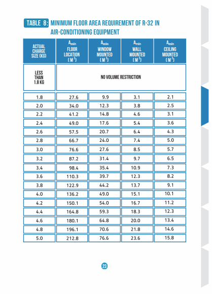
Table 8: Minimum floor area requirement of R-32 in Air-Conditioning equipment
Actual Charge
Less than
1.8 kgNo Volume Restriction
23

( M 2) ( M 2) ( M 2) ( M 2)
Amin
FLOORLOCATION Size (KG)
Amin
WINDOWMOUNTED
Amin
WALL MOUNTED
amin
CEILING MOUNTED
0.15
0.20
0.25
0.30
0.35
0.40
0.45
0.50
0.55
0.60
0.65
0.70
0.75
0.80
0.85
0.90
0.95
12.8
22.7
35.5
51.2
69.6
90.9
115.1
142.1
171.9
204.6
240.2
278.5
319.7
363.8
410.7
460.4
513.0
35.5
63.2
98.7
142.1
193.4
252.6
319.7
394.7
477.6
568.4
667.1
773.7
888.1
1,010.5
1,140.8
1,278.9
1,425.0
3.9
7.0
11.0
15.8
21.5
28.1
35.5
43.9
53.1
63.2
74.1
86.0
98.7
112.3
126.8
142.1
158.3
2.6
4.7
7.3
10.6
14.4
18.8
23.8
29.4
35.5
42.3
49.6
57.5
66.1
75.2
84.9
95.1
106.0
Actual Charge
Less than
0.15 kgNo Volume Restriction
24
Table 9 : Minimum floor area requirement of R -290 in Air-Conditioning equipment
4CHAPTER 4
GOOD SERVICING PRACTICES FOR FLAMMABLE REFRIGERANTS
25
©SHUTTERSTOCK
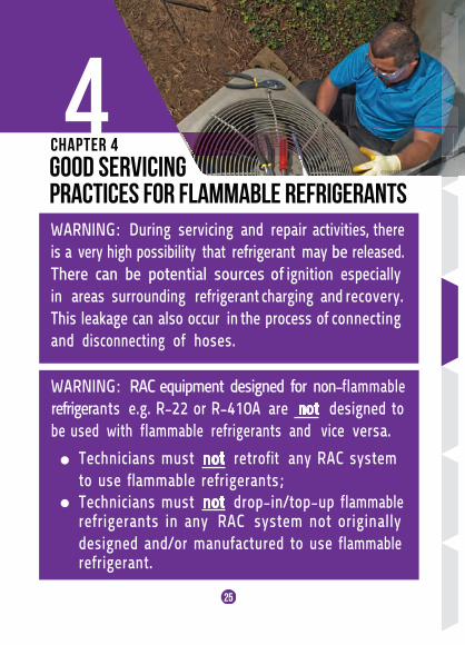
WARNING: During servicing and repair activities, there is a very high possibility that refrigerant may be released. There can be potential sources of ignition especially in areas surrounding refrigerant charging and recovery. This leakage can also occur in the process of connecting and disconnecting of hoses.
WARNING: RAC equipment designed for non-f lammable refrigerants e.g. R-22 or R-410A are not designed to be used with f lammable refrigerants and vice versa.
Technicians must not retrof it any RAC system to use f lammable refrigerants;Technicians must not drop-in/top-up f lammablerefrigerants in any RAC system not originally designed and/or manufactured to use f lammable refrigerant.
Technicians must not drop-in/top-up f lammablerefrigerants in any RAC system not originally designed and/or manufactured to use f lammable refrigerant.
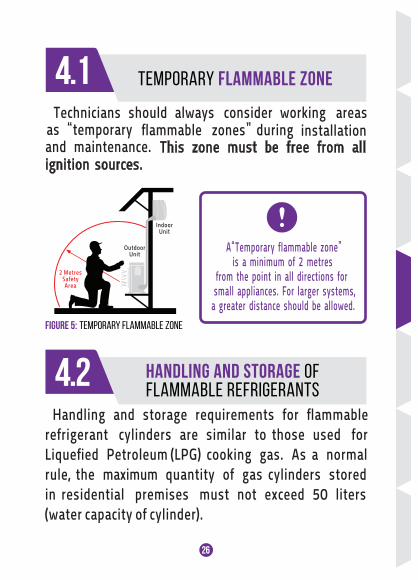
TEMPORARY FLAMMABLE ZONE4.1as “temporary f lammable zones” during and maintenance. ignition sources.
This zone must be free from all
IndoorUnit
OutdoorUnit
2 MetresSafetyArea
FIGURE 5: TEMPORARY FLAMMABLE ZONE
A“Temporary fIammable zone” is a minimum of 2 metres
from the point in all directions for small appliances. For larger systems, a greater distance should be allowed.
4.2 HANDLING AND STORAGE OFFLAMMABLE REFRIGERANTS
26
Handling and storage requirements for f lammable refrigerant cylinders are similar to those used forLiquef ied Petroleum (LPG) cooking gas. As a normal rule, the maximum quantity of gas cylinders stored in residential premises must not exceed 50 liters(water capacity of cylinder).
Technicians should always consider working areasinstallation
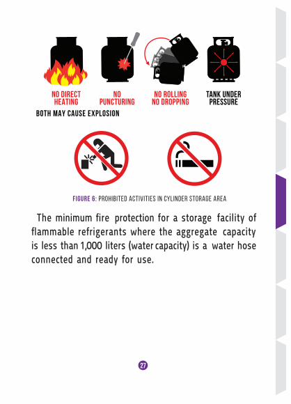
NO ROLLINGNO DROPPING
NO DIRECTHEATING
NOPUNCTURING
BOTH MAY CAUSE EXPLOSION
TANK UNDERPRESSURE
FIGURE 6: PROHIBITED ACTIVITIES IN CYLINDER STORAGE AREA
The minimum f ire protection for a storage facility off lammable refrigerants where the aggregate capacityis less than 1,000 liters (water capacity) is a water hose connected and ready for use.
27
28
The following precautions should be observed :
The storage area must be well ventilated and free of combustible materials.
Store the cylinders on the ground f loor andabove, but not in basements and other enclosed rooms. Keep the cylinders away from sources of heat and direct sun.
Don’t store the cylinders near sources of ignition (electrical sockets, power outlets, lightsand switches, electric motors and similar equipment).
Any potential
Protect the cylinders from falling or being knocked over.
ignition sources must be at least 3 metres
Have access to emergency services e.g. f ire, police etc.
Never place cylinders lying on their side.
away from the cylinder.
29
4.3General Requirements
SERVICING TOOLS AND EQUIPMENTFOR FLAMMABLE REFRIGERANT
Figure 7: Explosion-proof ventilation fan@ RDA-ENG.COM
Electrical and electronic tools used on systems containing f lammable refrigerants should be rated for use in a hazardous area.
The working area should be monitored with a leak detector designed for the refrigerant being installed/serviced to ensure that the concentration of refrigerant around working area does not exceed the limit.
A dry-powder or CO2 f ire extinguisher must be
available at the location.
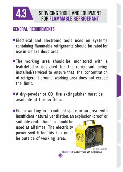
When working in a conf ined space or an area with insuff icient natural ventilation, an explosion-proof or suitable ventilation fan should beused at all times. The electricity power switch for this fan mustbe outside of working area.
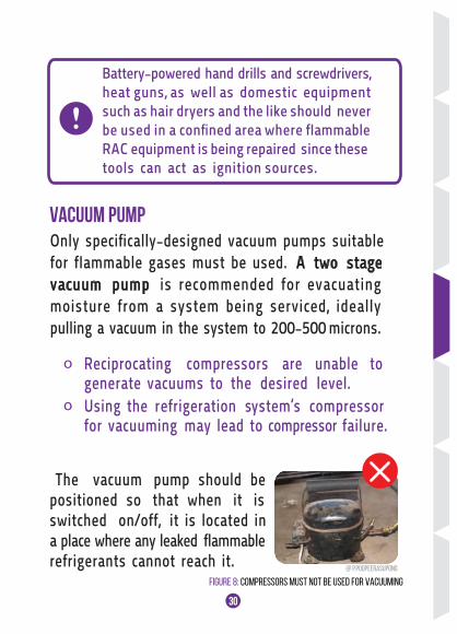
Figure 8: Compressors must not be used for Vacuuming@ P.POOPEERASUPONG
30
Vacuum Pump
o Reciprocating compressors are unable to generate vacuums to the desired level.
o Using the refrigeration system’s compressor for vacuuming may lead to compressor failure.
Battery-powered hand drills and screwdrivers,heat guns, as well as domestic equipment such as hair dryers and the like should neverbe used in a conf ined area where fIammableRAC equipment is being repaired since thesetools can act as ignition sources.
The vacuum pump should bepositioned so that when it isswitched on/off, it is located in a place where any leaked f lammablerefrigerants cannot reach it.
When working in a conf ined space or an area with insuff icient natural ventilation, an explosion-proof or suitable ventilation fan should beused at all times. The electricity power switch for this fan mustbe outside of working area.
Only specif ically-designed vacuum pumps suitable for fIammable gases must be used. A two stage vacuum pump is recommended for evacuating moisture from a system being serviced, ideally pulling a vacuum in the system to 200-500 microns.
31
Vacuum Gauge A vacuum gauge capable of reading pressure in the 5 - 5,000 micron range should be used when evacuating a system.
For electronic
gauges, ensure that they are designed for use in the presence of f lammable refrigerants
by checking the user manual.
Refrigerant Charging Equipment
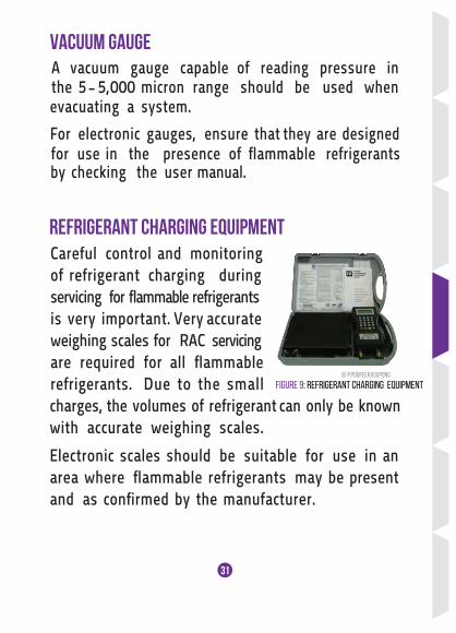
Figure 9: Refrigerant Charging Equipment@ P.POOPEERASUPONG
Careful control and monitoring of refrigerant charging during servicing for f lammable refrigerants is very important. Very accurate weighing scales for RAC servicing are required for all f lammable refrigerants. Due to the small charges, the volumes of refrigerant can only be known with accurate weighing scales.
Electronic scales should be suitable for use in an area where f lammable refrigerants may be present and as conf irmed by the manufacturer.
32
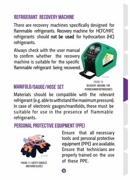
Refrigerant Recovery Machine
Figure 10:Recovery machine for
hydrocarbon refrigerants
@ CM-GREEN
@ CM-GREEN
There are recovery machines specif ically designed for f lammable refrigerants. Recovery machine for HCFC/HFC refrigerants should not be used for hydrocarbon (HC)refrigerants.
Always check with the user manual to conf irm whether the recovery machine is suitable for the specif ic f lammable refrigerant being recovered.
Materials should be compatible with the relevantrefrigerant (e.g. able to withstand the maximum pressure).In case of electronic gauges/manifolds, these must be suitable for use in the presence of fIammable refrigerants.
Manifold/Gauge/Hose Set
Personal Protective Equipment (PPE) Ensure that all necessary tools and personal protective equipment (PPE) are available.
Ensure that technicians are properly trained on the use
PPE .
FIGURE 11: SAFETY GOGGLES
AND HAND GLOVES
@ E.CLARK
of these
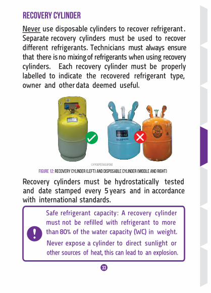
Safe refrigerant capacity: A recovery cylinder must not be refilled with refrigerant to more than 80% of the water capacity (WC) in weight.
33
Never use disposable cylinders to recover refrigerant .Separate recovery cylinders must be used to recover different refrigerants. Technicians must always ensurethat there is no mixing of refrigerants when using recoverycylinders. Each recovery cylinder must be properlylabelled to indicate the recovered refrigerant type, owner and other data deemed useful.
Recovery Cylinder
FIGURE 12: RECOVERY CYLINDER (LEFT) AND DISPOSABLE CYLINDER (MIDDLE AND RIGHT)
Recovery cylinders must be hydrostatically tested and date stamped every 5 years and in accordance
with international standards.
©P.POOPEERASUPONG
Never expose a cylinder to direct sunlight or other sources of heat, this can lead to an explosion.
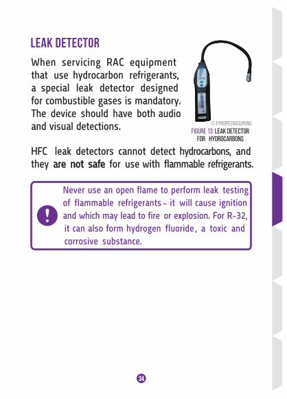
When servicing RAC equipment that use hydrocarbon refrigerants, a special lea k detector designedfor combustible gases is mandatory.The device should have both audioand visual detections.
34
Leak Detector
HFC leak detectors cannot detect hydrocarbons, and they are not safe for use with f lammable refrigerants.
Never use an open fIame to perform leak testing of f lammable refrigerants - it will cause ignition and which may lead to fire or explosion. For R-32, it can also form hydrogen f luoride , a toxic and corrosive substance.
Figure 13: Leak detector for hydrocarbons
© P.POOPEERASUPONG
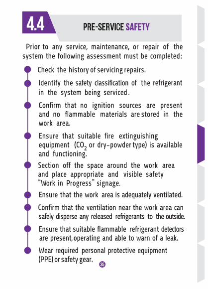
Prior to any service, maintenance, or repair of the system the following assessment must be completed:
Check the history of servicing repairs.
Identify the safety classif ication of the refrigerant in the system being serviced .
Conf irm that no ignition sources are present and no f lammable materials are stored in the work area.
Ensure that suitable f ire extinguishing equipment (CO2 or dry-powder type) is available
and functioning. Section off the space around the work area and place appropriate and visible safety “Work in Progress” signage.
Ensure that the work area is adequately ventilated.
Conf irm that the ventilation near the work area can safely disperse any released refrigerants to the outside.
Ensure that suitable f lammable refrigerant detectors are present, operating and able to warn of a leak.
Wear required personal protective equipment (PPE) or safety gear.
35
4.4
36
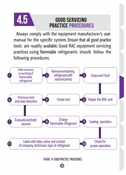
Sealing operation
4.5
FIGURE 14: GOOD PRACTICE PROCEDURES
Remove remaining refrigerant with vacuum pump
Clean and f lush
Repair the RAC unitChoke testPressure testand leak detection
1 2 3
Label with date, name and contact of company, technician, type of refrigerant
Check for proper operation10
45
Evacuate and hold vacuum
Chargef lammable refrigerant 98
6
7
11
Always comply with the equipment manufacturer’s usermanual for the specif ic system. Ensure that all good practice tools are readily available. Good RAC equipment servicingpractices using f lammable refrigerants should follow thefollowing procedures.
Safe recoveryor venting off lammablerefrigerant
GOOD SERVICING PRACTICE PROCEDURES
37
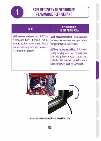
FIGURE 15: OPEN WINDOW OR DOOR FOR VENTILATION
Safe recovery or venting of flammable refrigerant1
R-32 HYDROCARBON (R-290 AND R-600A)
With recovery machine - As R-32 has a moderate GWP, it should not be vented to the atmosphere. Use a suitable recovery machine to recover R-32 from the system.
With recovery machine - Use a suitable recovery machine to recover hydrocarbonrefrigerants from the system.
Without recovery machine - Safely ventusing piercing pliers or piercing valve and a long hose to reach a safe area outside. Use suitable extractor fan oropen window or door for ventilation.
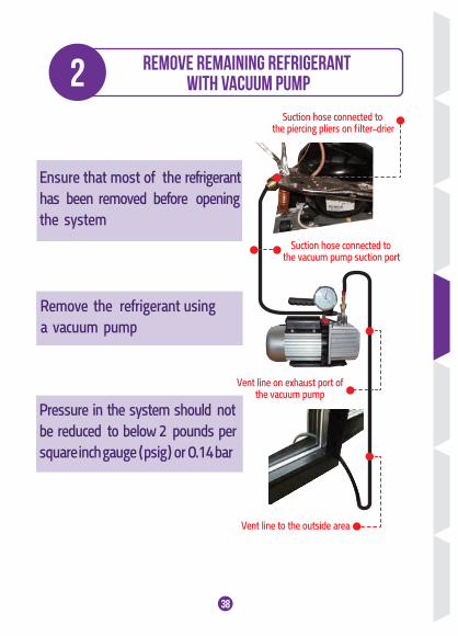
2 Remove remaining refrigerant with vacuum pump
Suction hose connected to the piercing pliers on f ilter-drier
Suction hose connected to the vacuum pump suction port
Vent line on exhaust port ofthe vacuum pump
Vent line to the outside area
Ensure that most of the refrigerant has been removed before opening the system
Pressure in the system should not be reduced to below 2 pounds per square inch gauge ( psig ) or 0.14 bar
Remove the refrigerant using a vacuum pump
38
3
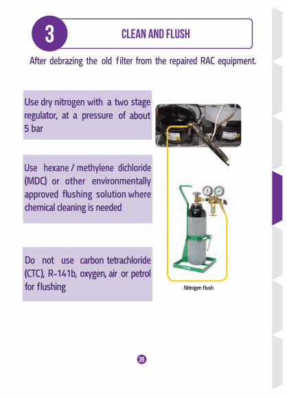
Nitrogen f lush
Clean and flUSH
39
After debrazing the old f ilter from the repaired RAC equipment.
4
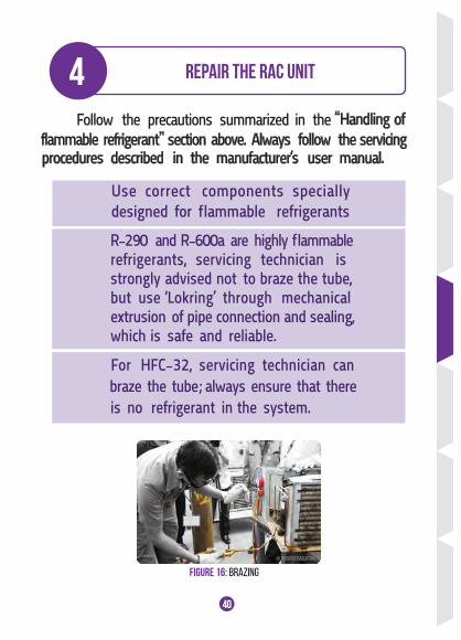
FIGURE 16: BRAZING
Repair the RAC unit
Use correct components specially designed for f lammable refrigerants
R-290 and R-600a are highly f lammable refrigerants, servicing technician is strongly advised not to braze the tube, but use ‘Lokring’ through mechanical extrusion of pipe connection and sealing, which is safe and reliable.
For HFC-32, servicing technician can braze the tube; always ensure that there is no refrigerant in the system.
40
@ P.POOPEERASUPONG
Follow the precautions summarized in the
flammable refrigerant” section above. Always follow the servicing procedures described in the manufacturer’s user manual.
“Handling of
5
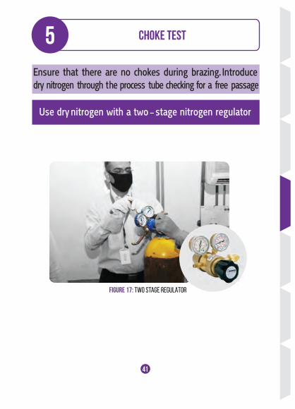
FIGURE 17: TWO STAGE REGULATOR
Use dry nitrogen with a two - stage nitrogen regulator
Choke test
41
Ensure that there are no chokes during brazing. Introduce dry nitrogen through t he process tube checking for a free passage
34
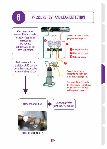
FIGURE 18: SOAP SOLUTION
6
Test pressure to be regulated at 20 bar andclose the cylinder valve
when reading 20 bar
Pressure test and leak detection
1
2
1
2
3
3
After the system is reassembled and sealed,
use dry nitrogen for leak testing. Do not use
compressed air norany refrigerant.
Use a soap solution Brush/spray each joint – look for bubbles
Connect a 4-valve manifoldgauge set to the system.
Low pressure side
High pressure side
Nitrogen supply
Connect the Nitrogen cylinder to the centre port of the manifold gauge set.
Pressurize the system withdry nitrogen while transferring the gas from both, the high and low pressure side
42
34
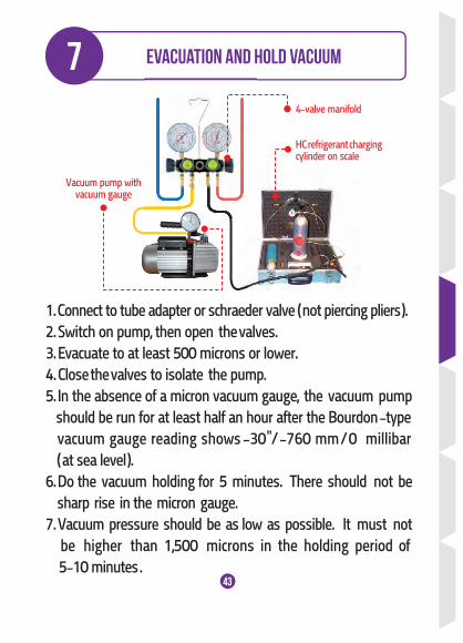
7 Evacuation and hold vacuum
4-valve manifold
Vacuum pump withvacuum gauge
HC refrigerant chargingcylinder on scale
1. Connect to tube adapter or schraeder valve ( not piercing pliers ).2. Switch on pump, then open the valves.3. Evacuate to at least 500 microns or lower.4. Close the valves to isolate the pump.5. In the absence of a micron vacuum gauge, the vacuum pump should be run for at least half an hour after the Bourdon -type vacuum gauge reading shows -30”/ -760 mm / 0 millibar ( at sea level ).6. Do the vacuum holding for 5 minutes. There should not be sharp rise in the micron gauge.7. Vacuum pressure should be as low as possible. It must not be higher than 1,500 microns in the holding period of 5-10 minutes . 43
8
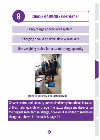
FIGURE 19: REFRIGERANT CHARGING TRAINING
Only charge an evacuated system
Charging should be done slowly/ gradually
Charge flammable refrigerant
Use weighing scales for accurate charge quantity
Greater control and accuracy are required for hydrocarbons because of the smaller quantity of charge. The actual charge size depends onthe original manufacturer charge, however it is limited to maximum charge as shown in the table 6, page 21
44
©P.POOPEE RASUPONG
9
FIGURE 20: LOKRING
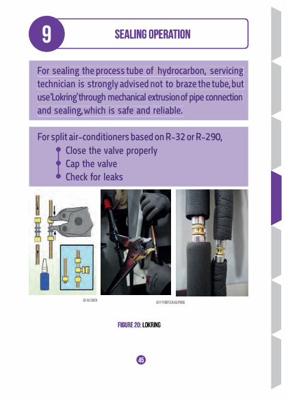
Sealing operation
45
@ P. POOPEERASUPONG
For sealing the process tube of hydrocarbon, servicing technician is strongly advised not to braze the tube, but use ‘Lokring’ through mechanical extrusion of pipe connectionand sealing, which is safe and reliable.
@ XU CHEN
For split air-conditioners based on R-32 or R-290,Close the valve properlyCap the valveCheck for leaks
9
FIGURE 20: LOKRING
For sealing the process tube of hydrocarbon, servicing technician is strongly advised not to braze the tube, but use ‘Lokring’ through mechanical extrusion of pipe connectionand sealing, which is safe and reliable.
Sealing operation
@ P. POOPEERASUPONG@ XU CHEN
11
10
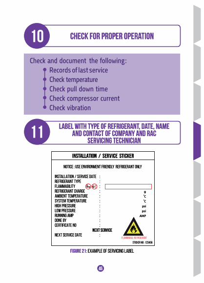
Label with type of refrigerant, date, name and contact of company and RAC
servicing technician
Check for proper operation
46
INSTALLATION / SERVICE STICKER
NOTICE : USE ENVIRONMENT FRIENDLY REFRIGERANT ONLY
INSTALLATION / SERVICE DATE :REFRIGERANT TYPE :FLAMMABILITY :REFRIGERANT CHARGE : gAMBIENT TEMPERATURE : ํCSYSTEM TEMPERATURE : ํCHIGH PRESSURE : psiLOW PRESSURE : psiRUNNING AMP : AMPDONE BY :CERTIFICATE NO :
NEXT SERVICE DATE :NEXT SERVICE
STICKER NO : 123456FIAMMABLE REFRIGERANT
FIGURE 21: EXAMPLE OF SERVICING LABEL
11
10
Label with type of refrigerant, date, name and contact of company and RAC
servicing technician
Check and document the following:Records of last serviceCheck temperature Check pull down timeCheck compressor currentCheck vibration
Check for proper operation
46
INSTALLATION / SERVICE STICKER
NOTICE : USE ENVIRONMENT FRIENDLY REFRIGERANT ONLY
INSTALLATION / SERVICE DATE :REFRIGERANT TYPE :FLAMMABILITY :REFRIGERANT CHARGE : gAMBIENT TEMPERATURE : ํCSYSTEM TEMPERATURE : ํCHIGH PRESSURE : psiLOW PRESSURE : psiRUNNING AMP : AMPDONE BY :CERTIFICATE NO :
NEXT SERVICE DATE :NEXT SERVICE
STICKER NO : 123456
FIGURE 21: EXAMPLE OF SERVICING LABEL
FLAMMABLE REFRIGERANT
5CHAPTER 5
DO AND DON’TCHECKLIST
47
©SHUTTERSTOCK
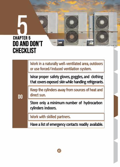
DO
Work in a naturally well-ventilated area, outdoors or use forced / induced ventilation system.
Keep the cylinders away from sources of heat anddirect sun.
Work with skilled partners.
Wear proper safety gloves, goggles, and clothing that covers exposed skin while handling refrigerants.
Have a list of emergency contacts readily available.
Store only a minimum number of hydrocarboncylinders indoors.
5CHAPTER 5
DO AND DON’TCHECKLIST
47
©SHUTTERSTOCK
DO
Work in a naturally well-ventilated area, outdoors or use forced / induced ventilation system.
Keep the cylinders away from sources of heat anddirect sun.
Work with skilled partners.
Wear proper safety gloves, goggles, and clothing that covers exposed skin while handling refrigerants.
Have a list of emergency contacts readily available.
Store only a minimum number of hydrocarboncylinders indoors.

48
Don’t
Do not smoke, drink or eat while in the work area.
Do not keep f lammable refrigerant in an area that has naked f lames, gas cookers, gas water heaters, gas/wood-fire room or space heaters.
Do not let f lammable refrigerants accumulate.
Do not store cylinder in basements and other enclosed rooms.
Do not work alone. At least two persons per site.
Do not place cylinders lying on their side.
Do not allow any ignition source within 3 metres of the cylinder.
48
Don’t
4749
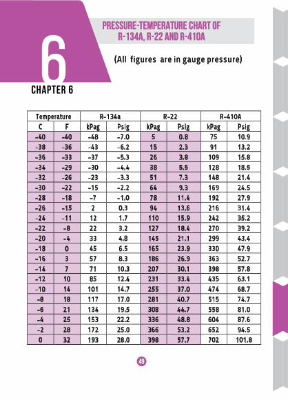
Temperature R-134a R-22 R-410A C F kPag Psig kPag Psig kPag Psig
-40 -40 -48 -7.0 5 0.8 75 10.9 -38 -36 -43 -6.2 15 2.3 91 13.2 -36 -33 -37 -5.3 26 3.8 109 15.8 -34 -29 -30 -4.4 38 5.5 128 18.5 -32 -26 -23 -3.3 51 7.3 148 21.4 -30 -22 -15 -2.2 64 9.3 169 24.5 -28 -18 -7 -1.0 78 11.4 192 27.9 -26 -15 2 0.3 94 13.6 216 31.4 -24 -11 12 1.7 110 15.9 242 35.2 -22 -8 22 3.2 127 18.4 270 39.2 -20 -4 33 4.8 145 21.1 299 43.4 -18 0 45 6.5 165 23.9 330 47.9 -16 3 57 8.3 186 26.9 363 52.7 -14 7 71 10.3 207 30.1 398 57.8 -12 10 85 12.4 231 33.4 435 63.1 -10 14 101 14.7 255 37.0 474 68.7 -8 18 117 17.0 281 40.7 515 74.7 -6 21 134 19.5 308 44.7 558 81.0 -4 25 153 22.2 336 48.8 604 87.6 -2 28 172 25.0 366 53.2 652 94.5 0 32 193 28.0 398 57.7 702 101.8
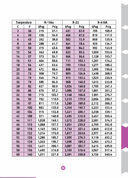
6Pressure-Temperature Chart of
R-134a, R-22 and R-410A Pressure-Temperature Chart of
R-134a, R-22 and R-410A
CHAPTER 6
(All figures are in gauge pressure)(All figures are in gauge pressure)
48
50
Temperature R-134a R-22 R-410A C F kPag Psig kPag Psig kPag Psig 2 36 215 31.1 431 62.5 755 109.5 4 39 238 34.5 466 67.6 810 117.5 6 43 262 38.0 502 72.9 868 125.9 8 46 288 41.7 541 78.4 929 134.7
10 50 315 45.6 580 84.2 992 143.9 12 54 343 49.8 622 90.2 1,059 153.6 14 57 373 54.1 666 96.6 1,128 163.7 16 61 404 58.6 711 103.1 1,201 174.2 18 64 437 63.4 759 110.0 1,277 185.2 20 68 472 68.4 808 117.2 1,356 196.6 22 72 508 73.7 859 124.6 1,438 208.5 24 75 546 79.2 913 132.4 1,523 220.9 26 79 585 84.9 968 140.5 1,612 233.8 28 82 627 90.9 1,026 148.8 1,705 247.3 30 86 670 97.2 1,086 157.5 1,801 261.2 32 90 715 103.7 1,148 166.6 1,901 275.7 34 93 762 110.5 1,213 175.9 2,004 290.7 36 97 811 117.6 1,280 185.6 2,112 306.3 38 100 862 125.0 1,349 195.7 2,223 322.4 40 104 915 132.8 1,421 206.1 2,338 339.1 42 108 971 140.8 1,495 216.9 2,457 356.4 44 111 1,028 149.1 1,572 228.0 2,581 374.3 46 115 1,088 157.7 1,651 239.5 2,709 392.8 48 118 1,149 166.7 1,733 251.4 2,840 412.0 50 122 1,214 176.0 1,817 263.6 2,977 431.8 52 126 1,280 185.7 1,905 276.3 3,118 452.2 54 129 1,349 195.7 1,995 289.3 3,263 473.2 56 133 1,421 206.1 2,087 302.7 3,413 495.0 58 136 1,495 216.8 2,183 316.6 3,567 517.4 60 140 1,571 227.9 2,281 330.8 3,726 540.4
49
51
Temperature R-32 R-290
(propane) R-600a
(isobutane) C F kPag psig kPag psig kPag psig
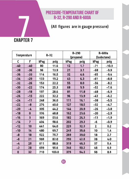
-40 -40 80 11.6 12 1.7 -71 -10.3 -38 -36 96 13.9 21 3.1 -68 -9.9 -36 -33 114 16.5 32 4.6 -65 -9.4 -34 -29 133 19.2 43 6.3 -61 -8.8 -32 -26 153 22.2 55 8.0 -56 -8.2 -30 -22 174 25.3 68 9.9 -52 -7.6 -28 -18 197 28.6 81 11.8 -48 -6.9 -26 -15 222 32.2 96 13.9 -43 -6.2 -24 -11 248 36.0 111 16.1 -38 -5.5 -22 -8 276 40.0 127 18.5 -32 -4.7 -20 -4 305 44.2 144 20.9 -26 -3.8 -18 0 336 48.8 162 23.6 -20 -2.9 -16 3 369 53.6 182 26.3 -13 -1.9 -14 7 404 58.6 202 29.3 -6 -0.9 -12 10 441 64.0 223 32.3 2 0.2 -10 14 480 69.7 245 35.6 10 1.4 -8 18 522 75.7 269 39.0 18 2.7 -6 21 565 82.0 293 42.5 28 4.0 -4 25 611 88.6 319 46.3 37 5.4 -2 28 659 95.6 346 50.2 48 6.9 0 32 710 103.0 375 54.3 58 8.5
7CHAPTER 7
Pressure-Temperature Chart of R-32, R-290 and R-600A
Pressure-Temperature Chart of R-32, R-290 and R-600A
(All figures are in gauge pressure)(All figures are in gauge pressure)

5052
Temperature R-32 R-290
(propane) R-600a
(isobutane) C F kPag psig kPag psig kPag psig 2 36 763 110.7 404 58.7 70 10.1 4 39 819 118.8 436 63.2 82 11.9 6 43 878 127.3 468 67.9 95 13.7 8 46 940 136.3 502 72.8 108 15.7
10 50 1,004 145.6 538 78.0 122 17.7 12 54 1,072 155.4 575 83.3 137 19.9 14 57 1,142 165.7 613 88.9 153 22.2 16 61 1,216 176.3 653 94.8 169 24.5 18 64 1,293 187.5 695 100.8 186 27.0 20 68 1,373 199.2 739 107.1 204 29.6 22 72 1,457 211.3 784 113.7 223 32.4 24 75 1,544 224.0 831 120.5 243 35.2 26 79 1,635 237.2 879 127.5 264 38.2 28 82 1,730 250.9 930 134.9 285 41.3 30 86 1,829 265.2 982 142.5 308 44.6 32 90 1,931 280.1 1,036 150.3 331 48.0 34 93 2,038 295.5 1,093 158.5 355 51.6 36 97 2,148 311.6 1,151 166.9 381 55.3 38 100 2,263 328.2 1,211 175.6 407 59.1 40 104 2,382 345.4 1,273 184.7 435 63.1 42 108 2,505 363.3 1,337 194.0 464 67.3 44 111 2,633 381.9 1,404 203.6 494 71.6 46 115 2,765 401.0 1,472 213.5 524 76.1 48 118 2,902 420.9 1,543 223.8 557 80.7 50 122 3,044 441.4 1,616 234.3 590 85.6 52 126 3,190 462.7 1,691 245.2 624 90.6 54 129 3,341 484.6 1,768 256.4 660 95.8 56 133 3,498 507.3 1,848 268.0 697 101.1 58 136 3,659 530.7 1,930 279.9 736 106.7 60 140 3,826 554.9 2,014 292.1 775 112.5
51
References
1. The Australian Institute of Refrigeration, Air-Conditioningand Heating (AIRAH), Flammable Refrigerants-Safety Guide,ISBN: 978-0-949436-05-4, 2013 (av ailable online athttps://www.airah.org.au/imis15_prod/Content_Files/TechnicalPublications/Flammable-Refrigerant-Safety-Guide-2013.pdf)
2. International Organization for Standardization (ISO), ISO5149-1:2014(E), Refrigerating systems and heat pumps –Safety and environmental requirements -Part 1 Def initions,classif ication and selection criteria, First Edition, 2014
3. United Nations Environment Programme, Good ServicingPractices: Phasing out HCFCs in the Refrigeration and Air-Conditioning Sector , 2015 (available online athttp://www.unep.org/ozonaction/Portals/105/Files/7723-e-Good%20Servicing%20Practices%20Phasing%20out%20HCFCs%20in%20the%20Refrigeration%20and%20 Air-Conditioning%20Servicing%20Sector_Training%20guide.pdf)
4. United Nations Environment Programme, Safe Use ofHCFC Alternatives in Refrigeration and Air-conditioning, 2015(available online athttp://www.unep.fr/ozonaction/information/mmcf iles/7740-e-SafeUseofHCFCAlternativesinRefrigerationandAir-conditioning.pdf)
53
References
52
5. GIZ Proklima publication “Good Practices in Refrigeration2010” (available online at https://www.giz.de/.../giz2010-engood-practic-esin-refrigeration.pdf)
6. Department of Environment Malaysia, Training Manual ForRefrigeration & Air-conditioning Servicing Sectors (RACS)First Edition, 2014.
Photo credits : © Shutterstock unless otherwise statedCover images : © Shutterstock
54
Photo credits : © Shutterstock unless otherwise statedCover images : © Shutterstock


www.unep.org UN Environment
P.O. Box 30552 Nairobi, Kenya Tel: ++254 -(0)20-762 1234 Fax: ++ 254 -(0)20-762 3927 E-mail: [email protected]
Copyright © UN Environment, 2016
For more information, contact: UN Environment, Economy Division OzonAction 1 rue Miollis, Building VII, 75015, Paris, France Tel: +331 4437 1450 Fax: +331 4437 1474 [email protected] www.unep.org/ozonaction
Muitilateral Fundfor the impiementation of the montreal protocol
www.unep.org UN Environment
P.O. Box 30552 Nairobi, Kenya Tel: ++254 -(0)20-762 1234 Fax: ++ 254 -(0)20-762 3927 E-mail: [email protected]
Copyright © UN Environment, 2016
For more information, contact: UN Environment, Economy Division OzonAction 1 rue Miollis, Building VII, 75015, Paris, France Tel: +331 4437 1450 Fax: +331 4437 1474 [email protected] www.unep.org/ozonaction


![Database Practices - Oracle FCIS 12.1.0 Database 12c ... … · Database Practices - Oracle FCIS 12.1.0 Database 12c Oracle FLEXCUBE Investor Servicing Release 12.3.0.2.1 [August]](https://img.pdfslide.us/doc/110x75/600639786ec1ac3e8a5ccb5c/database-practices-oracle-fcis-1210-database-12c-database-practices-.jpg)