Embed Size (px)
Citation preview
Good Practices in Installation and Servicing of Room Air-conditioners Refrigeration and Air-conditioning (RAC) Technicians Handbook

Financially supported by: Multilateral Fund (MLF) to the Montreal Protocol
Implemented by: The Ozone Cell of the Ministry of Environment & Forests (MoEF), Government of India, in co-operation with the Government of Germany represented by Deutsche Gesellschaft für Internationale Zusammenarbeit (GIZ) GmbH and United Nations Environment Programme (UNEP)

1
Good Practices in Installation and Servicing of Room Air-conditioners Refrigeration and Air-conditioning (RAC) Technicians Handbook
2013

2
Impr
int
ImprintPublished byDeutsche Gesellschaft für Internationale Zusammenarbeit (GIZ) GmbH Registered offices Bonn and Eschborn, Germany
Friedrich-Ebert-Allee 40 3113 Bonn, Germany Phone: +49 228 44 60-0 Fax: +49 228 44 60-17 66
Dag-Hammarskjöld-Weg 1-5 65760 Eschborn, Germany Phone: +49 61 96 79-0 Fax: +49 61 96 79-11 15 Email: [email protected] Internet: www.giz.de
Programme Manager: Bernhard Siegele ([email protected])
Name of Sector ProjectProgramme Proklima Dag-Hammarskjöld-Weg 1-5 65760 Eschborn, Germany
B-5/2, Safdarjung Enclave New Delhi 110029, India
Internet: www.giz.de/proklima
German Federal Ministry for Economic Cooperation and Development (BMZ) Environment and Sustainable Use of Natural Resources Division Bonn, Germany
AuthorsDr. Sukumar Devotta, Rolf Huehren, Dr. Atul Padalkar, Shashikant Juvekar
EditorsMarkus Wypior, Smita Vichare
Graphic DesignMayank Bhatnagar
New Delhi, June 2013

3
Abo
ut P
rokl
ima,
Ack
now
ledg
emen
tsAbout ProklimaProklima is a programme of the Deutsche Gesellschaft für Internationale Zusammenarbeit (GIZ) GmbH. Proklima has been providing technical and financial support for developing countries since 1996, commissioned by the German Federal Ministry for Economic Cooperation and Development (BMZ) to implement the provisions of the Montreal Protocol on Substances that Deplete the Ozone Layer.
This publication has been prepared under the project HCFC Phase-Out Management Plan Service Sector under Multilateral Fund (MLF) to the Montreal Protocol.
Acknowledgements We would like to thank Dr. Sukumar Devotta, Rolf Huehren, Dr. Atul Padalkar and Shashikant Juvekar for their valuable contribution to the handbook. This handbook is exclusively prepared for the Refrigeration and Air-conditioning (RAC) service technicians as a reference material for installation and servicing the air-conditioners charged with HCFC-22 refrigerant. Through this handbook the technicians are briefly introduced to alternative refrigerants to HCFC 22.
Few pictures in this handbook were taken from the book 'Good Practices in Refrigeration', published by GIZ-Proklima in March/ April 2010.
Markus Wypior, GIZ Smita Vichare, GIZ - Proklima

4
Dis
clai
mer Disclaimer
The information in this handbook and the procedures described are for use only by persons with the appropriate technical skills and training, at their own discretion and risk. The technical and legislative information presented is current at the date of original publication. Due to rapid advancing technology and changing regulations in this field, no representation can be made for accuracy of this information in the future.
The authors, reviewers of this document and Deutsche Gesellschaft für Internationale Zusammenarbeit (GIZ) GmbH and their staff do not endorse the performance or worker safety of any of the technical options, procedures described in this document. Every industrial operation requires consideration of worker safety and proper disposal of contaminants and waste products.
Version: June 2013

5
Cont
entsContents
• Imprint: Page 2
• About Proklima: Page 3
• Acknowledgements: Page 3
• Disclaimer: Page 4
• Contents: Page 5
• Introduction: Page 6
• Chapter 1: The Montreal Protocol: Page 7
• Chapter 2: Air-conditioning: Page 10
• Chapter 3: Environmental Impact of Refrigerants: Page 18
• Chapter 4: Tools and Equipment: Page 26
• Chapter 5: Copper Tubing Operations: Page 39
• Chapter 6: Quality Installation of Window and Split Air-conditioners: Page 46
• Chapter 7: Alternative Refrigerants to HCFCs: Page 58
• Chapter 8: Good Service Practices for Servicing and Repairing of Air-conditioners: Page 63
• Chapter 9: Recovery, Recycling and Reclamation of Refrigerants: Page 72
• Chapter 10: Safety and Maintenance: Page 80

6
Intr
oduc
tion Introduction
Good Practices in Installation and Servicing of Room Air-conditioners provides information to the reader of this handbook to introduce and upgrade their information on the subject of good practices during installation and servicing of air-conditioners.
In India the average consumption of HCFC-22 for servicing in 2009 and 2010 was 5,042 metric tonnes. This consumption is expected to exceed 10,000 metric tonnes by 2013 in a scenario with unconstrained growth. This is due to the high growth rate in particular in the room air-conditioner sub-sector. The demand projection for 2010-2030 clearly indicates that the servicing sector in the room air-conditioner sub-sector needs to be addressed in order to reduce India’s consumption of HCFCs.
The handbook for RAC technicians is prepared by GIZ Proklima for the technicians to be trained under HPMP project in India. The handbook provides preliminary and practical information to the technicians that can be applied on day-to-day basis during installation and servicing of air-conditioners. This handbook explains in a simple and easy to understand manner, the principles of air-conditioning, how the refrigerants if vented into the atmosphere have an impact on the environment. The technicians should always use the right hand tools and equipment for the right job, basic minimum tools and equipment required by technicians have been listed along with its applications. Good copper tubing forms one of the important tasks for proper functioning of the air-conditioners. This is explained step by step during the training with hands on practice. Incorrect installation can lead to high electricity bills, poor air circulation, as well as maintenance problems accurate installation of the window and split type room air-conditioners is highly imperative. When selecting alternatives to HCFCs, in addition to the conventional desirable properties of refrigerants, zero Ozone Depletion Potential (ODP) and low Global Warming Potential (GWP) are very important aspects to be considered, these have been briefly explained. Good servicing practices while repairing the air-conditioners together with following the safety measures and the 3Rs recovery recycling and reclamation of refrigerants, yield customer satisfaction, repeat orders and contribute to save the environment too.
The handbook is planned to be updated on a regular basis to integrate suggestions received and to keep pace with the evolving body of experience.

7
Chap
ter
1: T
he M
ontr
eal
Prot
ocol
Chapter 1 The Montreal Protocol
-10%
-25%
-32.5%
-30.25%

8
Chap
ter
1: T
he M
ontr
eal
Prot
ocol The international environment treaty the Montreal Protocol is widely
recognized as the most successful international regulation on ozone depleting substances (ODS) which were damaging the ozone layer. Almost all countries have ratified this agreement. The Protocol was ratified by India in 1992. Now, more than two decades later, this agreement is leading to the phase-out of consumption and production of several ODSs. The developed nations took the initiative for phasing out the production, consumption and emission of ozone depleting substances, followed by the developing nations.
The 19th Meeting of Parties (MOP) held in September 2007 in Montreal, decided to advance the phase-out of production and consumption of Hydrochlorofluorocarbons (HCFCs) by 10 years for an early recovery of the ozone layer (Decision XIX/6). HCFCs are not only ODSs, but also are potent greenhouse gases (GHGs). It is a challenging task, particularly to developing countries like India, to shift from HCFCs to environment-friendly alternatives.
As India is an Article 5 party to the Montreal Protocol and its amendments, it needs to phase-out HCFCs as per the accelerated phase-out schedule.
The phase-out schedule for Article 5 countries is:• Base-level for production & consumption: average of 2009 and 2010• Freeze of production & consumption by 2013 at the base level• 10% reduction by 2015• 35% reduction by 2020• 67.5% reduction by 2025• 100% reduction in 2030 with a service tail of 2.5% annual average during the period 2030-2040
Base
line
Per
cent
age
Year
2013-Freeze
-10%
-25%(-35%)
-32.5%(-67.5%)
-30.25%(-100%)
140
120
100
80
60
40
20
0
2005 2010 2015 2020 2025 2030 2035 2040

9
Chap
ter
1: T
he M
ontr
eal
Prot
ocolThe overall objectives of HCFC phase-out Management Plan
(HPMP) are:
1. Phase-out production and consumption of HCFCs in accordance with the Montreal Protocol phase-out schedule, without any commercial and financial dislocations in the country.
2. Achieving the compliance target set by the Montreal Protocol for Stage-I: • Establishment of base-line production and consumption sectors – an average of 2009 and 2010 for production and consumption respectively • 2013 freeze • 10% reduction of baseline in 2015
3. Phase-out of production and consumption of HCFCs to achieve the Stage-II reduction targets: 2020, 2025 and total phase-out in 2030, with an allowance for servicing on an annual average of 2.5% during the period 2030-2040.
HCFCs are being replaced by alternatives, like Hydrofluorocarbons (HFCs) and natural fluids. Worldwide, there are well established and energy efficient technologies available with non-ozone-depleting HFCs, particularly R-410A, in the unitary air-conditioning sector. But R-410A has a significant Global Warming Potential (GWP). A few industries are opting for HFC-32 as the alternative to HCFC-22. HFC-161 is another substitute for HCFC-22. The thermal stability tests on HFC-161 are under study. The long-term toxicity of HFC-161 is not yet established.
Due to environmental issues of high GWP refrigerants, natural fluids with negligible GWP are gaining more popularity for various applications, including room air-conditioners. Among the hydrocarbons, HC-290 has similar properties to HCFC-22. Many studies reveal that the performance of HC-290 in air-conditioners (AC) is better than HCFC-22. ACs with HC-290 have a far better energy efficiency than HCFC-22, while having heat transfer characteristics which are similar or superior to HCFC-22. The heat transfer coefficients are better for HC-290 for both condensation and evaporation.
The service sector in India has significant relevance as the total share of HCFC consumption in this sector is more than 40%. HCFC has a range of applications however it is widely used in room air-conditioners. Sustainable phase-out needs to include the service sector due to the risk of reverse conversions.

10
Chap
ter
2: A
ir-c
ondi
tion
ing
Chapter 2Air-conditioning

11
Chap
ter
2: A
ir-c
ondi
tion
ingThe American Society of Heating, Refrigerating and Air-conditioning
Engineers (ASHARE) define air-conditioning as “the process of treating air so as to control simultaneously its temperature, humidity, cleanliness and distribution to meet the requirements of the conditioned space”. For better comfort, the air in a room needs to be cooled or heated, humidified or dehumidified, purified and circulated. The normal temperature of a healthy human body is 36.89°C.
However, the general comfort temperature zone is 22.1°C to 26.7°C (a difference of 10-15°C below human body temperature). For comfort, relative humidity varies with the season. In winter, it is about 45-55% and in summer, it is about 50-60%. The air movement in the room should be in the range 5-12 m/s (16.4 – 39.4 ft/s). For a better rate of evaporation, the circulation of air is essential.
As the definition indicates, the important actions involved in the operation of an air-conditioning system are: • Temperature control • Humidity control • Air filtering, cleaning and purification • Air movement and circulation
Refrigeration has many applications. The first and most important is preservation of food. The other important uses of refrigeration include air-conditioning and humidity control.
Heat Transfer and RefrigerationHeat transfer takes place from a body at a higher temperature to a body at a lower temperature.
Refrigeration means the reduction of the temperature of a particular space or any substance. This is achieved by removing heat from the space where air-conditioning is required, or from the substance to refrigerate.
Refrigeration SystemA refrigeration system is divided into two parts. One is of high pressure (shown in red) and the other is of low pressure (shown in blue). As shown in figure 2.2 (overleaf ), the vapour compression refrigeration
Fig. 2.1 Heat Transfer
Hot Body Cold Body

12
system consists of components, such as: a condenser (1), a capillary/expansion device (2), an evaporator (3) and a compressor (4).
A vapour compression refrigeration cycle, as shown in figure 2.3, consists of four processes: (1) evaporation, (2) compression, (3) condensation, (4) expansion.
The liquid refrigerant which is at low pressure in a heat exchanger absorbs heat from a suitable source, e.g. air source or a body or
Chap
ter
2: A
ir-c
ondi
tion
ing
Figure 2.2 Refrigeration System
Figure 2.3 Refrigeration Cycle
1 3
2
4
Condenser
Evaporator
1
3
2
4
CompressorCapillary Tube
Low Pressure Side
High Pressure Side
13
Chap
ter
2: A
ir-c
ondi
tion
ingsubstance to be cooled, changing its state to vapour. The process of a
liquid refrigerant evaporating to a vapour state is called ‘evaporation’. The component in which evaporation takes place is called an ‘evaporator’. The design of an evaporator should be such that the refrigerant should reach a superheated state at its exit.
The low pressure refrigerant vapour enters the compressor and gets compressed. In this process, the pressure and temperature of the refrigerant increases substantially. The refrigerant entering the compressor should be dry and adequately superheated. The vapour which emerges from the outlet of the compressor is highly superheated.
After compression, the high pressure superheated refrigerant flows through a heat exchanger where heat is rejected to a suitable sink e.g. atmospheric air or cooling liquid. This heat exchanger is known as a condenser. The heat rejection in the first part of the condenser is known as desuperheating. The desuperheated refrigerant further rejects heat and it starts condensing in the heat exchanger to a liquid state. In the last part of the condenser, the condensed refrigerant is sub cooled.
When the high pressure condensed liquid refrigerant flows through the capillary, its pressure decreases. The capillary also controls the refrigerant flow or quantity into the evaporator. Hence, appropriate capillary diameter and length should be used.
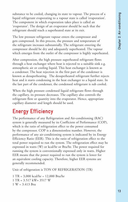
Energy EfficiencyThe performance of any Refrigeration and Air-conditioning (RAC) system is generally measured by its Coefficient of Performance (COP), which is the ratio of refrigeration effect to the power consumed by the compressor. COP is a dimensionless number. However, the performance of any air-conditioning system is indicated by its Energy Efficiency Ratio (EER). This is the ratio of refrigeration effect to the total power required to run the system. The refrigeration effect may be expressed in watts (W) or kcal/hr or Btu/hr. The power required for running the system is conventionally expressed only in watts. Higher EER means that the power required to run the system is lower for an equivalent cooling capacity. Therefore, higher EER systems are generally recommended.
Unit of refrigeration is TON OF REFRIGERATION (TR)
1 TR = 3,000 kcal/hr = 12,000 Btu/hr 1 TR = 3.517 kW= 3517 W 1 W = 3.413 Btu

14
Chap
ter
2: A
ir-c
ondi
tion
ing
Importance of Energy Efficiency The consumption of electricity will be less if air-conditioners have higher energy efficiency. Lower energy consumption leads to a reduction in the emissions of CO2 leading to reduction in global warming. Better servicing of air-conditioners also leads to reduction of emission of HCFC-22, resulting in reduction of ozone depletion and global warming. Technicians must remember that neither refrigerant leakage nor excess charging of refrigerant is good and they must improve servicing procedures.
In order to protect the environment, it should be ensured that air-conditioners consume less energy and avoid refrigerant leakages. The focus should be on achieving the best possible energy efficiency, with the lowest possible refrigerant emissions. This is a key to both environmental and economic sustainability.
Energy Labeling Standard for Air-conditionersThis standard specifies the energy labelling requirements for single-phase split and unitary air-conditioners of the vapour compression type for household use up to a rated cooling capacity of 11 kW. This is within the scope of IS1391 Part 1 and Part 2, being manufactured, imported, or sold in India. This standard shall be read in conjunction with IS1391 Part 1 and Part 2 with all amendments, as applicable.
Energy Labeling Scheme for Air-conditioners
The stars covered by the red shade indicate the Energy Star Rating of the AC
All ACs shall meet minimum 1 Star Energy Rating. 5 Star ACs have the highest energy efficiency and offer large savings to users Figure 2.4 Energy Label

15
Chap
ter
2: A
ir-c
ondi
tion
ingLarge rooms require higher cooling capacity of AC
Information related to technology variant
If AC with 1 Star costs electricity bill of Rs.100, AC with 5 Star will cost Rs.69
Choosing 5 Star Rated AC is good for you and for the environment
Energy Efficiency Rating value of the AC. Indicates amount of cooling produced in Watts for every Watt of electrical energy spent
Make and model details
Star Rating for Split Air-conditioners
Star Rating Plan
2010-11
Star Min Max
1 2.3 2.49
2 2.5 2.69
3 2.7 2.89
4 2.9 3.09
5 3.1
2012-13
Star Min Max
1 2.5 2.69
2 2.7 2.89
3 2.9 3.09
4 3.1 3.29
5 3.3
2013-14
Star Min Max
1 2.7 2.89
2 2.9 3.09
3 3.1 3.29
4 3.3 3.49
5 3.5
Figure 2.5 Star Rating for Split Air-conditioners
Cooling Capacity Upto 11kW)
Min
imum
EER
W/W
*
No Negative Tolerances on Minimum Value of the Band
01/2013 to 12/2015
01/2012 to 12/2013
01/2010 to 12/2011
*1 Watt = 3.413 Btu/hr
0
2.5
2.3
2.7

16
Chap
ter
2: A
ir-c
ondi
tion
ing
Air-conditionersWindow or spilt air-conditioners used for room cooling consist of the following basic parts: • A hermetic compressor, • A condenser, • An evaporator and a capillary tube for refrigerant flow control
Room air-conditioners are classified on the basis of their design and features. For example, window room air-conditioners are assembled and pre-charged systems, ready to plug in and operate on installation, while split room air-conditioners have to be assembled on the site and charged with refrigerant. In some models, electric resistance heating units are included for cold weather; they are called as a heat pump with a reversible cycle. Such systems allow for the selection of cooling or heating mode. For large buildings, central air-conditioning systems are applicable. These are called chillers.
Working of a Window Air-conditioner (WAC) The working of a window air-conditioner with approximate temperatures and air flow at various locations is shown in Figure 2.6. The colours indicate the temperature of hot or cold air and the refrigerant. Various components of the window air-conditioner, namely compressor, condenser, capillary, evaporator and fans, are shown.
Figure 2.6 Working of a Window Air-conditioner
Cooling coil (4.5°C) Absorbs heat from 24°C room air
12.5°C
Wall of house
Inside Temp. 24°COutside Temp. 36°C
Partition
FAN
Heat is pumped to the outside coil
Air enters side of unit at 35°C
Outside coil at 51.7°C can give up heat to 35°C outside air
Hot air is rejected to the outside. The outdoor coil receives most of its heat from the indoor coil through the refrigerant.
Heat is transferred from the 35°C room air into the 4.5°C coil. Room air passing over coil drops from 35°C to 12.5°C

17
Chap
ter
2: A
ir-c
ondi
tion
ingAlthough it is installed across a separation, indoor and outdoor, the
unit is an integrated single unit.
The difference between supply and return air should be between 10-12.5°C. This is explained under the topic ‘Air-conditioning comfort zone’.
Working of a Split Air-conditioner (SAC) The working of a split air-conditioner is shown in Figure 2.7, in this figure, air temperatures, relative humidity and movements are shown. This is very similar to the WAC but the unit is split into two parts, namely, Indoor Unit (IDU) and Outdoor Unit (ODU). The colours indicate the temperature of hot or cold air and refrigerant.
Figure 2.7 Working of a Split Air-conditioner
Compressor
IndoorOutdoor
Outside Air 35°C
Room Air 24°C 50% RH
Evaporator
Condenser
Metering Device
75% Liquid25% Vapour
FAN
FAN
10°C
15.6°C93.3°C
51.7°C
51.7°C
51.7°C
4.4°C
4.4°C
40.5°C
12.8°C Air Approx.
4.4°C
4.4°C
69 psig
278 psig
278 psig
278 psig 69 psig
278 psig
69 psig
Wall of House

18
Chap
ter
3: E
nvir
onm
enta
l Im
pact
of
Refr
iger
ants
Chapter 3 Environmental Impact of Refrigerants

The depletion of the ozone layer and climate change are the two major environmental concerns. It was noticed that the chlorine and bromine elements in synthetic refrigerants, viz. HCFCs, CFCs, and Halons were responsible for the depletion of ozone in the earth’s atmosphere. Another major issue is the global warming potential due to halocarbons, PFCs, HFCs, HCFCs, CFCs, Halons and industrial gas emissions.
Ozone Depleting Potential (ODP) and Global Warming Potential (GWP)The international regulation, the Montreal Protocol, mandates the phase-out programme of ozone depleting substances and the Kyoto Protocol deals with greenhouse gases.
ODP is a measure of the ozone depleting potential or capability of a refrigerant with respect to that of CFC11 which has an ODP of 1.0. GWP is an index which compares the warming effect over time, of different gases, relative to equal emission of CO2 by weight. Table 3.1 presents the ODP and GWP values of select refrigerants.
Stratospheric Ozone LayerIn the stratosphere, ozone layer formation and destruction is simultaneous and continuous. In the ozone layer, the UV rays from the sun react with the existing oxygen molecules and break them into oxygen atoms. The following reaction is where the diatomic oxygen and single atom of oxygen join together to form an ozone molecule. Thus, oxygen is partially converted into ozone all the time. The reverse
19
Chap
ter
3: E
nvir
onm
enta
l Im
pact
of
Refr
iger
ants
Refrigerant ODP GWP
CFC-11 (R11) 1 4750
CFC-12 (R12) 1 10900
HCFC-22 (R22) 0.055 1810
HFC-134a (R134a) 0 1430
HFC-32 (R32) 0 675
R-407C 0 1824
R-410A 0 2088
HC-290 0 3
Table 3.1 ODP and GWP Values of Select Refrigerants

20
Chap
ter
3: E
nvir
onm
enta
l Im
pact
of
Refr
iger
ants
Ozone is a gas that occurs naturally in the atmosphere. It is a tri-atomic form of oxygen (O3) and an unstable molecule. It is found in a layer of the earth’s upper and lower atmosphere known as the stratosphere, about 15-50 km above the earth’s surface. Ozone has a strong odour and is blue. Ozone absorbs the sun’s harmful UV-B radiation and protects living organisms. Although ozone represents only a small fraction of the gas present in the atmosphere, it plays a vital role by shielding humans and other forms of life from harmful ultraviolet light from the Sun. In the past several decades, humans have produced chemicals, such as chlorofluorocarbons (CFCs) and others, which, when released into the atmosphere, have contributed to the depletion of this important protective layer.
Figure 3.1 Ozone Layer
MESOSPHERE
STRATOSPHERE
PROTECTIVE NATURAL OZONE LAYER
TROPOSPHERE
Supersonic Aircraft
Damaging Industrial Ozone
Mount Everest
Research Baloons
Altitude (Kms)
5 10 15 20
Limit of most clouds

is also true. Some ozone is also decomposed into three oxygen atoms, which join together in twos to become oxygen molecules. Thus, a continuous equilibrium is maintained between ozone and oxygen in that zone.
The amount of stratospheric ozone overhead on any given day and at any given location varies quite a bit. Because of vertical circulations of air in both the troposphere and the stratosphere, there can be greater or lesser amounts of ozone protecting the earth from ultraviolet radiation. Also, the populations living at higher elevations or closer to the sun e.g. Australia people are exposed to more UV radiation than in countries at lower elevations.
While stratospheric ozone which protects the earth from the sun is good, the ground level ozone produced due to atmospheric pollution in cities is harmful for human health. It causes breathing problems for some people and usually occurs during summer when the pollution over a city builds up.
The ozone layer depletion drew the attention of all when it was discovered that certain man-made chemicals called chlorofluorocarbons (CFCs) find their way up to the stratosphere where, through a complex series of chemical reactions, they destroy some of the ozone. As a result of this discovery, an international treaty was signed in 1987 called the Montreal Protocol, and the manufacture of these chemicals has been greatly reduced.
Destruction of Ozone When a CFC molecule reaches close to the ozone layer, it triggers a chain of reactions which initiate ozone layer depletion. Firstly, on coming in contact with sun’s UV rays, a CFC molecule decomposes and releases chlorine radical. This chlorine radical reacts with a molecule of ozone, yielding an oxygen molecule and a chloromonooxide molecule.
This chloromonooxide molecule, being unstable, breaks and releases a free chlorine radical. This chlorine radical now starts yet another cycle of similar reaction with another ozone molecule, and once again returns to its chlorine radical state. Thus, through these repetitive cycles, the ozone layer gets continually depleted in the presence of the CFCs.
Overleaf, in fig. 3.2, a sample of CFC is shown - this is also applicable for HCFCs. Later, oxygen in the atmosphere reacts with Cl-O molecule and produces free chlorine (Cl) radical and diatomic oxygen
21
Chap
ter
3: E
nvir
onm
enta
l Im
pact
of
Refr
iger
ants

(O2). This chlorine again destroys another ozone molecule into oxygen as a chain reaction. With the presence of C-H bond in the molecule, HCFCs are much less stable in the atmosphere than CFCs. Therefore, HCFCs have lower ODPs than CFCs.
Ozone is measured in Dobson units (DU). 100 DU is equivalent to the quantity of ozone that would form a layer 1 mm thick at sea level, if compressed at Standard Temperature and Pressure (STP). The typical distribution is 240 DU near the equator. The size of the ozone hole increased progressively from 1979 to 2011.
The ozone level has fallen to 107 DU. However, in September 2012, the ozone level had substantially improved and the lowest value observed, was around 220 DU.
22
Chap
ter
3: E
nvir
onm
enta
l Im
pact
of
Refr
iger
ants
Figure 3.2 Destruction of Ozone by CFCs
Figure 3.3 Status of Ozone
Cycle begins again
Chlorine radical breaks bond in ozone molecule
Creates chlorine monoxide and
diatomic oxygen
Oxygen is released into atmosphere
Oxygen atom in atmosphere
Breaks bond in chlorine monoxide
molecule
Produces diatomic oxygen and free chlorine radical
UV energy removes chlorine atom from CFC
molecule
UVB
Depletion was more in Sept 2008 and have recovered in Sept 2012
Sept 2008 Sept 2012
Total Ozone (Dobson Units)

Effects of Ozone Layer DepletionIf UV radiation reaches the earth, it has harmful effects on human life, plants, trees, aquatic life and even on man-made and natural materials. It damages DNA and suppresses the immune system, resulting in an increase in infectious diseases, skin cancer and eye cataracts.
Other effects are on plants and trees, such as reduced production of crops and poorer quality, as well as damage to seeds. It also affects aquatic life, damaging plankton, aquatic plants, shrimps and crabs. When the marine food chain is affected, fisheries suffer.
Materials are also affected by UV radiation. Paints, rubber, wood and plastic get degraded, especially in tropical regions. The value of this damage could go into billions of US dollars.
Global Warming Apart from ozone depletion, another threat due to refrigerants like CFCs and HCFCs, is global warming. Global warming is the long-term increase in atmospheric temperature and it is global in nature. The gases which cause increase in the temperature of the atmosphere are called Greenhouse Gases (GHGs). The GHGs such as carbon dioxide (CO2), methane (CH4), nitrous oxide (NO), sulphurhexafluorides (SF6), hydrofluorocarbons (HFCs), and
23
Chap
ter
3: E
nvir
onm
enta
l Im
pact
of
Refr
iger
ants
Figure 3.4 Effects of Ozone Layer Depletion
Damage to aquatic life
Damage to skin
Infectious diseases
Damage to plants and crops

perfluorocarbons (PFCs), essentially emitted by human activity, cause an increase in global warming and this is harmful to mankind.
It disturbs the balance between hot and cold areas in the atmosphere. If the concentration of GHGs is increased, there is a rise in temperature. GHGs act like a blanket around the earth, trapping heat and resulting in a rise in temperature.
Effects of Global WarmingAn increase in the temperature of the atmosphere results in the melting of ice at the poles and a rise in the sea level. It destroys coastal towns, leaving people living in coastal areas, homeless. There are changes in water supply and water quality. Habitat is damaged and plants and animal species are affected.
In the last 100 years, the mean global temperature has increased by 0.3-0.6°C. Due to global warming, the sea water thermally expands and the icecaps melt, leading to rising sea levels. An increase in global sea level of 4 to10 inches has been observed over the last 100 years. This also affects the rainfall pattern, leads to climate changes and thereby alters biodiversity. It also has a negative effect on human health, as evidenced by the increase in cases of Malaria, Dengue and Yellow Fever.
24
Chap
ter
3: E
nvir
onm
enta
l Im
pact
of
Refr
iger
ants
Figure 3.5 Global Warming
Some of the infrared radiation passes
through the atmosphere but most is absorbed and re-emitted in all
directions by greenhouse gas molecules and
clouds. The effect of this warms the Earth’s surface and the lower
atmosphere.
The Greenhouse EffectSolar radiation powers the climate system.
Some solar radiation is reflected by the Earth and the atmosphere.
About half the solar radiation is absorbed by the Earth’s surface and warms it.
Infrared radiation is emitted from the Earth’s surface.
Earth
Atmosphere
SUN

According to experts, the world will see a definite impact of global warming in the next few decades. The increase in global temperatures, coupled with the burgeoning population, will make society more vulnerable to climate change. Climatic disorders, droughts, famines, floods and longer heat waves will spread to newer areas. Tropical islands and low-lying coastal areas will face the threat of being submerged.
25
Chap
ter
3: E
nvir
onm
enta
l Im
pact
of
Refr
iger
ants
Figure 3.6 Effects of Global Warming
Rising sea level
Habitat damage and species affected
Increased temperatures
Changes in water supply

26
Chap
ter
4: T
ools
and
Equ
ipm
ent
Chapter 4Tools and EquipmentTools and Equipment

27
Chap
ter
4: T
ools
and
Equ
ipm
entRefrigeration and air-conditioning service technicians work mainly
with hand tools and equipment. To be successful, the technicians must select quality tools, take good care of them and be skilled in their use. The technicians should always use the right hand tools and equipment for the right job and as recommended by the manufacturer of the air-conditioner. Using improper equipment and tools for a specific job may be unsafe. For example, using a flat screwdriver instead of a Phillips screwdriver - the flat screwdriver tip may slip and result in personal injury. Use of appropriate equipment and tools helps in improving the quality of installation as also repairs and servicing
Spanners and ScrewdriversThe use of box-end and socket spanner-cum-screwdriver (set of 41 pieces) is the best choice when there is adequate space around the nut and bolt.
The plastic handle with assorted drive socket of six points, can be used for effective and speedy work. The size marked on the socket must be checked while selecting the screwdriver bit.
The various types of screwdriver bits e. g. flat-bladed key stone/cabinet, Phillips type, Allen type, Bristol, etc. can be used as per the requirement. A sturdy screwdriver of No. 8 with a firmly-bonded plastic handle can be used to remove or fit screws while servicing and installing systems. The screwdriver should not be pounded with a hammer.
Allen Keys, Wrenches and PliersAllen keys are made up of a hexagonal metal bar and can be used to tighten nuts having hexagonal recess on the head. The Allen key set comes with various sizes and it is useful for new air-conditioners.
Ratchet wrench/service valve wrench [Sockets 6.35 x 4.76 mm (1/4”
Figure 4.1 Spanners and Screwdrivers

28
Chap
ter
4: T
ools
and
Equ
ipm
ent
x 3/16”) square & 14.28 x 12.7 mm (9/16” x 1/2”) hexagonal]. (are usually constructed with a square end ratchet that is reversible. This helps for easy and quick work without change of tool/bit. The adjustable spanner 150 mm (6”) is a popular type of adjustable wrench (spanner) necessary for opening / fixing odd-sized nuts and bolts.
Crimping pliers are necessary for crimping closed end-splices and fixing fastener clips to the ends of wires. These can be used to cut and strip wire. These can be also used for crimping solder-less connectors onto wires. They can be used to cut small bolts too.
Pliers and SpannersDifferent pliers/wrenches need to be used as per the requirement. Insulated combination pliers 150 mm (6”) size] help to grip objects and to strip or cut wires. This is a handy tool for general use. For safety, it is not advisable to use this on nuts, bolts or fittings. To grip a small hardware or to strip or cut wires, insulated nose pliers are recommended. This helps to work in a narrow work space. To grip big objects like tubes, nuts or bolts, monkey pliers 100 mm (4”) size can be used.
Spanners: Common types of spanners include open-end spanner, the box spanner and combination spanners. There are also tube-type spanners and adjustable spanners.
Figure 4.2 Allen Keys, Wrenches and Pliers
Figure 4.3 Pliers

29
Chap
ter
4: T
ools
and
Equ
ipm
ent
Files and CuttersDepending on the requirement, various types of files can be used to remove unwanted burrs while doing operations on tubes or other metal surfaces.
A Flat Rough File 200 mm (8”) with a safe handle is recommended when metal is to be removed at a faster rate from a flat surface. A Round File 150 mm (6”) can be used for cleaning metal surfaces and shaping metal parts in a circular shape.
For cutting copper tubes used in the installation and maintenance work of air-conditioners, a hacksaw (blade with frame size 300 mm (12”) is ideal. Hammer and mallet (400/500 g) are useful hand tools for accurate blows onto metal for bending or shaping as required, during the servicing or installation of air-conditioners.
Chisels and knives are used for cutting metals or metallic wires. A flat cold chisel 20 mm (0.78”) size is needed for cutting metals, where as a knife can be used for cutting/shredding small size wires.
Sealants and Sealing ValveAdhesives are recommended for bonding plastic parts together. Some common adhesives are:
Colloidal solution: This sets to a hard film, bonding materials together.
Insulation tape roll: This is used to cover exposed electrical contacts for safety purposes. This tape is a plastic film, covered with an adhesive material to insulate live electrical wires.
Teflon tape: This prevents leakages when applied on a threaded part. However, Teflon tape should not be used to cover flared connections of air-conditioners.
Figure 4.4 Files
Figure 4.5 Sealing Valve

30
Fuse wire: This is a low melting point wire which protects appliances from any damage due to voltage fluctuation. Hence, it should be appropriately rated, standard electric protective device.
Multi-meter and Digital Thermometer Before starting any electrical work, an insulated electric tester (500 V) should be used to test live electric supply in wires and sockets. The electric tester also helps to check polarity in the electric socket.
The multifunctional digital clamp meter aids to check resistance, AC/DC voltage and current. It measures resistance in the range 0-200kΩ, DC voltage up to 1000V, AC voltage up to 750V and AC current 0-300 A.
It can be used as continuity/diode tester with an audible beep. The technician can record measured value from the display. It has peak hold/data hold buttons. Teardrop jaw design provides maximum accessibility for measurement.
A digital thermometer with a puncture probe is an instrument to measure the temperature and humidity. This has an accurate electronic signal with indoor and outdoor temperature display. The indicator displays the temperature between -50°C to 100°C with Fahrenheit/Centigrade conversion switch.
Charging Kit and Leak DetectorThe portable gas charging station has hoses with female quick couplers, refrigerant measuring cylinder/weighing balance, manifold, high vacuum pump, vacuum gauge and pressure gauges. This helps to charge the air-conditioners with the exact amount of refrigerant. Small disposable cans and cylinders containing 1 to 2.5 kg refrigerant are available in the market. The empty cylinders should be carefully disposed off. The system must be checked for leakages after charging it with the refrigerant.
Chap
ter
4: T
ools
and
Equ
ipm
ent
Figure 4.6 Multi-meter and Digital Thermometer

31
An electronic leak detector must be used to check for leakages through joints. It rapidly pinpoints the source of the leak. By eliminating contamination with selected filters, false alarms can be avoided. Audio/visual indication helps with leak detection. A leak detector (<5 g / year) with high sensitivity must be used.
Tube CutterTube bender, cutter and flare tools are the important devices required for the installation or servicing of air-conditioners. A tube cutter designed to cut annealed /soft copper tubes up to 20 mm (0.78”) diameter must be used for installation and servicing of air-conditioners. Normally, a tube cutter has reamers attached. The reamer is used to remove burrs at the edges of the cut tube.
For speedy work, as far as possible avoid the use of a tube cutter to cut the tube into small pieces. Instead, use readily available tubes cut into 120 mm (4.72”) and 150 mm (6”) pieces. While carrying out maintenance of the system at the place of the customer, use a floor protector to prevent damaging and dirtying of the floor.
Chap
ter
4: T
ools
and
Equ
ipm
ent
Figure 4.7 Charging Kit and Gas Leak Detector
Figure 4.8 Tube Cutter

32
To avoid any damage while cutting a capillary tube, a compact tube cutter instead of a large tube cutter, must be used at work.
Spring-type and lever-type tube benders are available. For the tube not to get damaged or pinched while bending, it is recommended to use a spring-type tube bender.
PliersFinally, while servicing or installing air-conditioners, all tubes require to be pinched-off by pinch-off pliers/self-locking pliers. These are ideal tools for this purpose. These pliers can also be used for clamping jaws in any position. For piercing tubes, quick-piercing pliers/valves can be applied, e.g. quick-tube-piercing valve fits 6.35 mm (1/4”) tube fitted with 6.35 mm (1/4”) SAE threads. Use connectors to control the flow of fluid by raising and lowering a needle that fits into a matching set.
To avoid leakage of refrigerant, male and female quick couplers are suitable for quick and instant fitment with valve. This will save time as well as save the material. Apply this for 6.35 mm (1/4”) copper tubes.
Brazing KitTo make a closed refrigerant circuit, brazing at joints is required. Brazing is a process of joining metals together by melting at high temperature through a burner, using LPG. An LPG brazing kit is suitable for this purpose. A portable brazing kit consists of a brazing torch, nozzle, hose, regulator, spanner and lighter.
Chap
ter
4: T
ools
and
Equ
ipm
ent
Figure 4.9 Pliers

33
Before brazing, joints must be properly prepared to make a stronger joint. It is advised to use emery cloth/paper for polishing all joints for better brazing results, through capillary action. Use a scrubber / wire brush to clean the metal joints after brazing.
During brazing, much heat is generated. An asbestos-lined heat deflector must be used to reflect the heat on to the joints while brazing. This also saves plastic or similar materials, from getting burnt. After brazing, use a telescopic mirror to inspect brazed joints for leaks.
Tongs and Fire ExtinguisherTongs are used to lift hot objects.
Fire Extinguisher (ABC powder type 2 kg or 5 kg) must be kept handy for safety.
Pressure Gauges and Torque WrenchesA compound gauge is useful to measure pressure at the low and high sides of a running system.
A thermo-couple vacuum gauge is useful for measuring the fine vacuum which is difficult to measure using a compound gauge. This gauge measures the vacuum in microns.
Chap
ter
4: T
ools
and
Equ
ipm
ent
Figure 4.10 Brazing Kit
Figure 4.11 Tongs and Fire Extinguisher
Figure 4.12 Pressure Gauge

34
(1 micron = 0.001mm i.e. 1/1000mm Hg).
This can be also used to check leakage by the Pressure Rise Test.
A set of torque wrenches (several heads) for up to 200 Nm (2039 kgf-cm) and hardware (springs, screws, washers, nuts, bolts, bearings, rivets etc.) are required for the servicing of air-conditioners.
4-way ManifoldA 4-way gauge manifold is an essential tool for air-conditioning and refrigeration technicians. This reads pressures on both high and low sides of the system. This can also be applied to read vacuum on the low-pressure side of the system.
Refrigerant Hoses The various types of hoses are refrigerant standard hose, vacuum hose, refrigerant hose with end-mounted ball valve and specially designed HC refrigerant venting hose.
Refrigerant standard hose is with 50.8 mm x 6.35 mm (2” x 1/4”) SAE
Chap
ter
4: T
ools
and
Equ
ipm
ent
Figure 4.13 Four Way Manifold
Support barManifold bodySight glass for refrigerant flowLow pressure valveVacuum Pump
High pressure valveValve connection for charging cylinder or recovery unitHose connection 1/4" male flare SAEVacuum hose connection 1/4" and 3/8"

35
size with female flare connections of 900 mm (35.43”) length. It can withstand working pressure up to 52 bar (754 psi).
Vacuum hose is with 50.8 mm x 9.5 mm (2” x 3/8”) female flare SAE connection. For minimal refrigerant emission while charging, the refrigerant hose with end-mounted ball valve must be used.
The specially designed HC refrigerant venting hose, of minimum 10 m (32.8 ft) length is with 12.7 mm (1/2”) ID, vacuum pump connector and dilutor.
Flaring and Swaging ToolFlaring and swaging of copper tubes during servicing should be done with the aid of flaring and swaging tools. Levers or mechanical benders should be used for the installation of room air-conditioners.
Soldering Iron (230 volt, 25 watt) A soldering iron is used for soldering and disconnecting electronics or electrical components, wires etc. Soldering wire with flux can be used for soldering and cleaning electronic components, electrical components, wires etc.
Measuring Tape, Spirit Level, Reamer and TorchReamer / Burr remover removes the burr of cut copper tubes from the inner edge as well as from the outer edge.
When the intensity of light is too low, the handy torch can be used.
Chap
ter
4: T
ools
and
Equ
ipm
ent
Figure 4.14 Refrigerant Hoses
Figure 4.15 Flaring and Swaging Tool
36
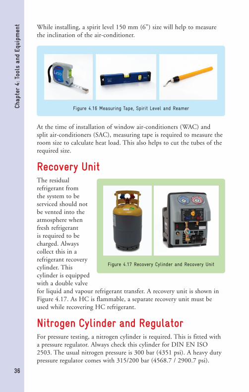
While installing, a spirit level 150 mm (6”) size will help to measure the inclination of the air-conditioner.
At the time of installation of window air-conditioners (WAC) and split air-conditioners (SAC), measuring tape is required to measure the room size to calculate heat load. This also helps to cut the tubes of the required size.
Recovery UnitThe residual refrigerant from the system to be serviced should not be vented into the atmosphere when fresh refrigerant is required to be charged. Always collect this in a refrigerant recovery cylinder. This cylinder is equipped with a double valve for liquid and vapour refrigerant transfer. A recovery unit is shown in Figure 4.17. As HC is flammable, a separate recovery unit must be used while recovering HC refrigerant.
Nitrogen Cylinder and RegulatorFor pressure testing, a nitrogen cylinder is required. This is fitted with a pressure regulator. Always check this cylinder for DIN EN ISO 2503. The usual nitrogen pressure is 300 bar (4351 psi). A heavy duty pressure regulator comes with 315/200 bar (4568.7 / 2900.7 psi).
Chap
ter
4: T
ools
and
Equ
ipm
ent
Figure 4.16 Measuring Tape, Spirit Level and Reamer
Figure 4.17 Recovery Cylinder and Recovery Unit

37
Working pressure is 0 -100 bar (0 -1450 psi). A nitrogen hose with a ball valve is used along with the nitrogen cylinder.
Brush, Oil Can and Allen Keys To remove dust from the grill, motor, etc. of an air-conditioner, a 50 mm (2”) paint brush is required.
During servicing of air-conditioners, oiling of the fan motor is required to be done. An oil can is required for the purpose of better lubrication.
‘T’ Allen key is required to open the Allen screw of the fan blade and fan blower.
‘T’ box spanner is required to dismantle compressor mounting nuts.
Fin Comb and Velocity Meter Fin tool/comb is a special tool that is designed to straighten/clean the condenser and evaporator fins. For maximum efficiency of the system, regular maintenance of the system is required.
Air velocity meter (vane type anemometer) measures the air velocity for balancing the air-conditioning ventilation system.
Chap
ter
4: T
ools
and
Equ
ipm
ent
Figure 4.18 Pressure Regulator
Figure 4.19 Brush and Allen Keys
Figure 4.20 Fin Comb and Velocity Meter

38
Chap
ter
4: T
ools
and
Equ
ipm
ent
Light Weight Air Blower, Hand Drill Machine and Noise TesterA light weight air blower is used to remove dust particles from the evaporator and condenser coil of air-conditioners. Its high velocity air jet blows dust and other contaminants from the coils.
A hand drill machine is used to drill holes in the sheet metal spare for fitting of screws also to drill holes at the time of installation.
A corded or battery operated dB meter or noise tester is required to measure the noise level of the blower in the air-conditioner.
Figure 4.20 Drill Machine, Air Blower and Noise Meter

39
Chap
ter
5: C
oppe
r Tu
bing
Ope
rati
ons
Chapter 5 Copper Tubing Operations

40
Chap
ter
5: C
oppe
r Tu
bing
Ope
rati
ons Most tubing used in refrigeration and air-conditioning (RAC) is made
of copper. All tubing in RAC is carefully processed to be sure that it is clean and dry inside. The ends must be kept sealed until it is used. RAC tubing is usually charged with gaseous nitrogen. Nitrogen should be fed through the tubing during brazing operations. Copper tubing operations in RAC include straightening, cutting, reaming, bending, cleaning, polishing, swaging soft-drawn copper tubing, flaring soft drawn copper tubing and brazing.
Copper TubingCopper tubes are available with ASTM and ISI standards for RAC tubing. ASTM or IS10773 standard tubes offer desired design, purity, size, compatibility with refrigerants, and safety. The tubes used in air-conditioners are measured on the basis of the outside diameter. Air-conditioning and refrigeration tubes are classified on the basis of thickness of tubes.
Three types of copper tubes are available in the market:
K Class: Thick-walled tubes used for heavy duty applications. L Class: Medium thick-walled tubes which are used widely in almost all applications. (L and K class tubes are suitable for room air-conditioners.) M Class: Thin-walled tubes, rarely used in the RAC industry and not recommended.
Copper Tubing OperationsThe operations done on the copper tubing are straightening, cutting, reaming, bending, swaging soft-drawn copper tubing, flaring soft-drawn copper tubing and brazing. All these operations need to be done carefully, with good servicing practices. Using accurate sizes of copper tubes will correctly fit into each in a telescopic from (e.g. 5/8 to ½” , ½ to 3/8”, 3/8 to ¼ “. (15.8 mm to 12.7 mm, 12.7 mm to 9.5 mm, 9.5 mm to 6.3 mm)
Straightening Straightening is the first step in copper tube processing. Figure 5.1 shows the operation of straightening of copper tube used in air-conditioners. The straightening has to be done from the head to the tail of the tube. Before cutting the tube, marking it is important. The part marked is to be safely placed on a flat surface, avoiding any damage to the tube.

41
Chap
ter
5: C
oppe
r Tu
bing
Ope
rati
ons
CuttingCutting of copper tubes has to be done precisely. The cutting of the tube should be done using a tube cutter. The surface of the cut part should not be rough or slanted. It should be at a right angle to the axis of the tube and smooth. If more pressure is applied on the cutter,
the tube gets pinched and some burr occurs. The tube should not be twisted while cutting. Cut through the tube till the edge of the cutter reaches the bottom of the other side of the tube. The cutter should be selected as per the size of the copper tube to be cut. Neither a file nor any other tool apart from a cutter must be used for cutting the tube. It is recommended to cap the tube ends when not in use.
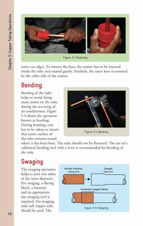
ReamingWhile reaming, the face of the tube and the reamer should be facing each other without any deviation. Figure 5.3 shows the reaming operation. On cutting the tube, there will be burr on the inner and
Figure 5.1 Straightening
Figure 5.2 Cutting
Pipe Cutter
Slanted Rough90o
42
Chap
ter
5: C
oppe
r Tu
bing
Ope
rati
ons
outer cut edges. To remove the burr, the reamer has to be inserted inside the tube and rotated gently. Similarly, the outer burr is removed by the other side of the reamer.
BendingBending of the tube helps to avoid doing many joints on the tube during the servicing of air-conditioners. Figure 5.4 shows the operation known as bending. During bending, care has to be taken to ensure that entire surface of the tube remains round where it has been bent. The tube should not be flattened. The use of a calibrated bending tool with a lever is recommended for bending of the tube.
SwagingThe swaging operation helps to join two tubes of the same diameter. For swaging, a flaring block, a hammer and an appropriate size swaging tool is required. For swaging, only soft copper tube should be used. The
Figure 5.3 Reaming
Figure 5.4 Bending
Figure 5.5 Swaging
Normal diameter tubing end
Connected swaged tubing
Swaged tube end

43
Chap
ter
5: C
oppe
r Tu
bing
Ope
rati
onsswage tool is inserted in the soft tube, and then hammered gently
till the diameter of the tube is increased to the desired size. The swaged end of the tube can then be fitted into another tube of normal diameter (that is, one which has not been swaged).
Flaring To join the copper tube with male threaded flare fitting perfectly in the air-conditioner, a flaring operation has to be performed. The end of the soft copper tube is flared at a 45o angle. The flared end of the tube rests against the male threaded part of the tube fitting being connected.
For the flaring operation, a flare block and a flaring yoke are required. The point to be noted is that in this connection, there is metal to metal contact without a gasket and pressure in the system is about 30 bar (435 psi). Therefore, proper attention is essential while doing the flaring process. The detailed procedure is shown in Figure 5.6.
Cleaning and Polishing - Surface Preparation The surface and edges of the copper tube have to be cleaned so that there will be no burr or dust left inside the tubes after joining them. Figure 5.7 shows the surface cleaning and polishing.
Figure 5.6 Flaring
Yoke
Handle
ConeBar
Bar
Copper Pipe
Figure 5.7 Cleaning (L) and Polishing (R)

44
Chap
ter
5: C
oppe
r Tu
bing
Ope
rati
ons
Insulating TubesAir-conditioning and refrigeration tubes are normally insulated on the low pressure side. In order to absorb heat, the tube section between evaporator and compressor is not generally insulated. Insulation prevents condensation around the tubes. Before applying the insulation over the tubes, the Inner Diameter (ID) of the insulation material is normally powdered for better slippage over the surface and bends of the tubes. In many cases, insulation is provided by wrapping insulation material around the tubes. Here, care has to be taken that no gaps are left between the tube and the insulation material. Proper insulation and correct procedure, ensures satisfactory performance of the tubes. Figure 5.8 shows how copper tubes are insulated while servicing of air-conditioners, to avoid heat loss.
BrazingBrazing is a process of joining metal and/or alloy. It is covered under ‘hot processes of metal joining’. In room air-conditioners, brazing is a possible and suitable process for copper to copper, copper to aluminum and copper to steel tube joints. Such joints give the tubes used in air-conditioners better strength and resistance against shocks, vibrations and tension.
Before starting the brazing process, the tubes are required to be prepared. The tubes should be of adjacent size viz. ¼” to 3/8” (6.3 mm to 9.5 mm). If they are of the same size, on one side of the pipe, swaging will have to be done. Clearance between two tubes should be in the range 0.05 mm to 0.2 mm. The length of the joint should at least be equivalent to the diameter of the tubes, in the case of same size tubes, or 1.5 times the diameter of the female tube, whichever is higher. The surface and ends of the tube must be cleaned. While inserting the smaller diameter end into the larger diameter end of the tube, the tubes must be kept straight and aligned with each other.
Before commencement of brazing, the joints of the tubes should be properly cleaned. This is followed by the removal of the dirt on the
Figure 5.8 Insulating Tubes

45
Chap
ter
5: C
oppe
r Tu
bing
Ope
rati
onstubes by thoroughly cleaning the surfaces of the tubes to be joined
together, with emery paper or wire brush, leaving them clean and bright. This will ensure the removal of all the dirt, greases, oils and other impurities that will otherwise be present on the surfaces and prevent the proper wetting of the surfaces. The next step is to check that the clearance between the two tubes that are to be joined is accurately maintained. The ideal clearance to be maintained between the tubes would be between 0.05 mm to 0.20 mm. For tubes with the same diameter, good results will be achieved from brazing if the right tools are used to swage the tubes.
While brazing, maintaining the correct temperature is very important. The appropriate temperature will be achieved by using the right combination of fuel, torch and flame. Using Oxy-Acetylene or Oxy-LPG fuel and torches gives the best results. Air LPG fuel and torches can also be used, but blowlamps using kerosene should be avoided as they do not give the necessary temperature for brazing.
The right filler rods are to be used for brazing. For copper (Cu) to copper brazing, filler rods that contain 7.5% phosphorus and the balance Cu (known as Phos Cu) can be used without a flux, as phosphorus itself, acts as a good flux. Brazing rods with 2% silver (Ag) can also be used, preferably with a flux, as Ag lowers the melting temperature. For Cu to Ferrous (Fe) brazing, filler rods containing phosphorus are to be strictly avoided and rods containing at least 35% Ag have to be used with a flux; the balance composition of the rods is cadmium (Cd) and Zinc (Zn).
While brazing, the base metals (i.e. the tubes) should be heated with the flame in a manner that facilitates the flow of the molten filler rod into the clearances of the tube. Figure 5.9 shows the brazing process in refrigeration and air-conditioning.
Figure 5.9 Brazing
Base Metal
Torch
Flux
Filler Metal
46
Chap
ter
6: Q
uality
Ins
tall
atio
n of
Win
dow
and
Spl
it A
ir-c
ondi
tion
ers
Chapter 6 Quality Installation of Window and Split Air-conditioners

Implementation of correct installation practices is very important, as it has quite a bearing on the actual working of the air-conditioners. Incorrect installation can lead to high electricity bills, poor air circulation, as well as maintenance problems. Many studies have proven that the improper installation of air-conditioners reduces their capacity and efficiency by more than 20%. In fact, appropriate installation of the air-conditioner is an important practice in order to maintain an economical, efficient and comfortable cooling system.
General Safety for InstallationThe technician must learn and follow safety and good service practices while installing air-conditioners. It should be mandatory that only qualified, trained and experienced technicians do installation of air-conditioners. All safety rules like proper electrical connections, switching off the main power supply while working on the system, grounding the air-conditioner as per code, not installing air-conditioners near hot surroundings, checking for leakage of refrigerant, pre and post cleaning of location, working in ventilated area, no components left inside the air-conditioner, are to be followed when at work.
Tools and Equipment for InstallationThe minimum set of tools and equipment required for installation of air-conditioners are:
1. A screw driver set 2. Phillips head screw driver 3. Knife or wire stripper 4. Steel tape measure 5. Spirit level 6. Hacksaw 7. Core bits for drilling 8. Hammer 9. Drilling machine 10. Tube cutter 11. Tube flaring tool 12. Tube bender 13. Torque wrench 14. Adjustable wrench 15. Reamer (for deburring) 16. Refrigeration (thermal) insulation tape 17. Insulated staples for connecting electrical wires 18. Putty
47
Chap
ter
6: Q
uality
Ins
tall
atio
n of
Win
dow
and
Spl
it A
ir-c
ondi
tion
ers

19. Clamps or saddles to protect the refrigerant tubes 20. Thermometer 21. Multi-meter or clamp tester or tong testser. 22. Guage manifold 23. Thermometer 24. Tong tester 25. Clamp meter 26. Brazing cap 27. Vaccum pump
Power Point Before starting installation of the air-conditioner, electrical connections have to be verified for rated current, voltage, and phase connections on rhs of socket as shown in Figure 6.1. The technician should ensure that adequate earthing, as per national standards, is provided.
Installation of Window Air-conditionerLocationFor installation of window air-conditioners (WAC), the location should be based on the frame size. The distance of the lower side of the WAC above the floor, should be more than 1000 mm. The distance of the
48
Chap
ter
6: Q
uality
Ins
tall
atio
n of
Win
dow
and
Spl
it A
ir-c
ondi
tion
ers
Figure 6.1 Checking Electrical Sockets
Figure 6.2 Selection of Proper Location
Opening in frame to be of (b x a) Height x Width = (Height x Width of air-conditioner) + 2-4 mm, c = 250 mm (min), d = 1000 mm (min) and e = 500 mm (min)
a
b
c
d
e

top or upper side of the WAC above the floor should not be more than 2000 mm (78.7”). WAC must be placed at least 1500 mm (59”) away from other electronic appliances (for example, TV) to avoid the interference of waves, away from direct heat to minimize heat addition and in a wall of minimum 250 mm (9.8”) thickness. It should be safe for children and free from dampness. The external part of the air-conditioner should be in the shade. Other dimensions of various air-conditioner sizes and capacities, with allowances for open spaces, are given in Figure 6.2.
Steps for WAC Installation The technician must follow the installation procedure as per the manufacturer’s installation booklet. The following are work instructions / guidelines for technicians:
1. Place the unpacked unit safely, with its accessories, on the work table. 2. Remove the grille and filter. 3. Remove the cabinet base tray locks. 4. Pull out the base tray/unit from the cabinet. 5. Install the cabinet inclined backward/outward slightly, 4 - 6 mm (0.15” - 0.23”) 6. Drill 8 holes of 6 mm (0.23”) diameter on the wooden frame. 7. Fix the outer cabinet firmly to the wooden frame. 8. If required, apply grease to the bottom of the base tray and channels. 9. Slide the base tray into the outer cabinet with adequate care of all the tubes. 10. Confirm that all accessories are fitted and hand over leftover materials to the customer. 11. Make a single unit as shown in the manual of the air-conditioner being installed. 12. Fill thermal insulation between the outer cabinet and the wooden frame. 13. Ensure proper and clean appearance of the installed unit. 14. Fit anti-theft locks, if provided with the air-conditioner. 15. Install the filter, grille and drain tray to the base tray from outside. 16. Connect the power cord to the power point and switch on the electrical power to the unit. 17. Set the control panel as desired and start the air-conditioner. 18. Run the air-conditioner for about 20-25 minutes. 19. Demonstrate the effective use and benefits and explain the features of the air-conditioner to the customer. 20. Fill up the warranty documents provided with the air-conditioner.
49
Chap
ter
6: Q
uality
Ins
tall
atio
n of
Win
dow
and
Spl
it A
ir-c
ondi
tion
ers

50
Chap
ter
6: Q
uality
Ins
tall
atio
n of
Win
dow
and
Spl
it A
ir-c
ondi
tion
ers 21. Record all observations as a report and fill up the checklist.
22. Take your leave of the customer and the site along with all belongings.
Air LeakagesIn order to avoid the leakage of air, gaps between the doors and windows and around the outer cabinet of WAC, must be filled in with insulation material. All gaps must be sealed. The technician should ensure that no gaps are left in the room.
Installation of Split Air-conditionerIn the case of split air-conditioner, the evaporator is located at a higher position as compared with the window air-conditioner. Cool air has more density than hot air. The air which comes in contact with the evaporator coil gets cooled and cooled air being higher in density, flows
in the downward direction towards the floor. The warm air moves up as it is lighter than rest of the air in the room. This phenomenon has been shown in figure 6.3.
Location for Indoor Unit (IDU)For quality installation of IDU, a strong wall, away from direct heat and breeze, is necessary. There should not be any obstruction to the circulation of air. There should be adequate space, more than 150 mm (6”), around the IDU. The distance between the ceiling and the IDU should be more than 50 mm (2”) in the case of front suction or
Figure 6.3 Proper Location for SAC

51
Chap
ter
6: Q
uality
Ins
tall
atio
n of
Win
dow
and
Spl
it A
ir-c
ondi
tion
ers
grille design and more than 150 mm (6”) in the case of top suction or flat front panel design. For the drain, the tube should slope towards the outside of the wall. The location should be away from flammable materials and the tubing should have minimum bends and elbows. A hole should be drilled in the wall for the drain tube, refrigerant tubes and electrical cable, based on all these mentioned aspects.
Location for Outdoor Unit (ODU)For quality installation of ODU, a strong foundation is required, away from direct heat. There should be no obstruction to air circulation. The space around the ODU must be more than 150-250 mm (6”– 9.8”) in the rear and more than 1500 mm (59”) in front of the unit. It should be placed away from any flammable materials. If there is a shade above the ODU, it will improve its performance. Avoid locating
Figure 6.4 Proper Location for Indoor Unit (IDU)
Figure 6.5 Proper Location for Outdoor Unit (ODU)
More than
5 cms
More than
5 cms
More than
6 cms
More than
eye-level
150mm 150mm
1500mm
250mm

52
Chap
ter
6: Q
uality
Ins
tall
atio
n of
Win
dow
and
Spl
it A
ir-c
ondi
tion
ers the ODU where it would be exposed to salty atmosphere. The tubing
should have minimum bends and elbows.
Installation of IDUFollowing are the steps for installation of the IDU:
1. Align the installation plate on the wall horizontally, and mark locations for fasteners. Using the spirit level, mark the vertical centre line. 2. Drill 6 mm (0.23”) holes at the marked points, insert sheaths/ plugs and fit the installation plate with eight screws. 3. Then, open the cover of the hole of the plastic tube as per suitable direction for drainage.4. Drill a hole of 70 & 100 mm (2.7” & 4”) diameter for 1.0 TR and 2.0 TR units respectively for tubing and wires.5. The holes must be slightly sloping, 4 - 6 mm towards the outdoor side.6. Drill the tubing hole on the right or left side of the installation plate as per the drain line.7. Use a special conduit for allowing the tubes to smoothly slide out.
Installation of ODUThe following instructions have to be followed while installing the ODU:
1. Ensure that the base for installation of the ODU is rigid.2. In case the site is located where the breeze is strong, or if it is at a high altitude, install the ODU lengthwise along the wall, using a shield to protect the working of the fan. Ensure that the air does not enter the ODU. Select a site for ODU in such a way that its access is easy for installation and future servicing.
Figure 6.6 Installation of IDU
70-100mm 70-100mm
At Least 60mm
Fasten string at the central hole
Plumb

53
Chap
ter
6: Q
uality
Ins
tall
atio
n of
Win
dow
and
Spl
it A
ir-c
ondi
tion
ers3. If the drainage is bad, or if water is likely to accumulate near
the outdoor unit, place the ODU on a concrete block or raised platform, if possible.
4. If the outdoor unit vibrates too much, adjust the angle of the installation legs. In case the unit is likely to tilt or fall, bolt it with 8 mm (0.31”) diameter anchor bolts.
Installation of SAC TubesFollowing are the steps for the installation of refrigerant tubes. The technician should follow the procedure for installation of tubes without any deviation.
1. Make a hole of 70 -100 mm (2.75” – 4”) diameter in the wall (L or R) for taking out tubes, drain tube and wires. 2. Measure the distance between the IDU and ODU, including all bends. 3. Cut the tubes a little longer than the measured distance. 4. Remove burrs from the cut edges of the tubes. 5. Remove the flare nut from the tube end. 6. Flare the tube ends after inserting flaring nuts. 7. Tape the flaring portion to protect it from dust or damage. 8. Align the centres of both flares at both IDU and ODU. Tighten the flare nuts. 9. Insulate all tubes for better performance and evacuate tubes to 500 microns. 10. Connect the drain hose and extend it with rigid tube if required. 11. Insulate the drain hose laid indoors. The drain hose should be inclined downward. 12. Remove filters and pour water into the drain pan to confirm the smooth flow of water.
Figure 6.7 Installation of ODU

54
Chap
ter
6: Q
uality
Ins
tall
atio
n of
Win
dow
and
Spl
it A
ir-c
ondi
tion
ers For connecting the IDU and ODU with the compressor, copper tubing
is necessary. When the height between the IDU and ODU is about 3 m (9.8 ft), then the length of the tube should be 5 m (16.4 ft), and when the height is 7 m (22.9 ft), then the length should be 10 m (32.8 ft). In installation, various color codes for tubes carrying liquid and gaseous refrigerant, drain and 3 core electrical wires, are used. It is essential that the drain tube should be inclined so that condensate drains out. In the case of a drain tube placed like a siphon, the condensate will not flow. Apply torque that is just right for flare nuts. Over tightening the flare nuts shears the tubes, ultimately resulting in leaks.
Installation of SAC Power ConnectionsThe technician must follow the instructions / guidelines and procedure given by the original manufacturer of air-conditioners:
1. Cut the electrical cable 1500 mm (59”) longer than the length of the tube. 2. Ensure adherence to colour codes of the wires and use only suggested wires. 3. Refer to the standard wiring diagram pasted on the unit (IDU & ODU). 4. Ensure that earthing is provided at the appropriate places. 5. Do not allow the electrical wiring to touch the refrigerant tubing, compressor, other components of the air-conditioner 6. Place batteries in the remote controller as necessary. 7. Operate the service valves to allow refrigerant flow in SAC. 8. Connect the power cord to the power point and switch on the electrical power supply to the unit. 9. Set the control panel as desired and start the air-conditioner. 10. Permit the air-conditioner to run for about 20-25 minutes. 11. Give a demonstration for effective use. 12. Fill up the warranty documents of the air-conditioner. 13. Record all observations as a report and fill up the checklist on completing the installation. 14. Before leaving the site, collect all the belongings. 15. Take your leave politely of the customer.
Additional Refrigerant Quantity for SACThe quantity of refrigerant specified by the manufacturer may not be sufficient if the distance between the IDU and ODU is different/longer than suggested by the manufacturer. Usually the standard length of tubing is 4 m (13.1 ft) only. Additional refrigerant/gas charge quantity varies with the length and diameter of refrigerant tubing.

55
Chap
ter
6: Q
uality
Ins
tall
atio
n of
Win
dow
and
Spl
it A
ir-c
ondi
tion
ersAdditional Charge is Calculated as:
For 6.35 mm (1/4”) liquid tube and 12.7 mm (1/2”) gas tube with a total measured length of 15 m (49.2 ft), the additional charge will be approximately 256 g of HCFC-22. The technician must use the table given here below. Alternatively, OEMs need to be contacted or their service manuals must be referred to for this purpose.
Service Valves for SACSchematic diagrams of a two-way valve used on the liquid side and a three-way valve used on the gas side are shown in Figure 6.8. The technician must follow the connections of the tubes with the valves as shown in Figure 6.8 at the time of SAC installation. Use proper keys and not any tool. Here, a 3-way valve can be used for evacuation and/or gas charging.
Post-Installation Check-up The following is a questionnaire for evaluation of work done:
1. Is the air-conditioner installed securely? 2. Is there enough space provided around the IDU and ODU for better performance?3. Is anything obstructing the circulation of air?4. Are all gaps around the unit filled with thermal insulation?
Table 6.1: Additional Refrigerant Charge
Gas Tube dia g/m Liquid Tube dia g/m
12.7 mm (1/2”) 1.87 6.35 mm (1/4”) 21.38
15.87 mm (5/8”) 3.71 7.94 mm (5/16”) 37.16
19.05 mm (3/4”) 5.58 9.52 mm (3/8”) 57.66
Figure 6.8 Two and Three Way Valves
Flare Nut
To Piping Connection
To Piping Connection
To Outdoor Unit To Outdoor Unit
Open Position
Closed Position
Hexagonal wrench (4mm)
Vavle Cap
Flare NutOpen Position
Closed Position
Pin
ServicePort Cap
ServicePort

56
Chap
ter
6: Q
uality
Ins
tall
atio
n of
Win
dow
and
Spl
it A
ir-c
ondi
tion
ers
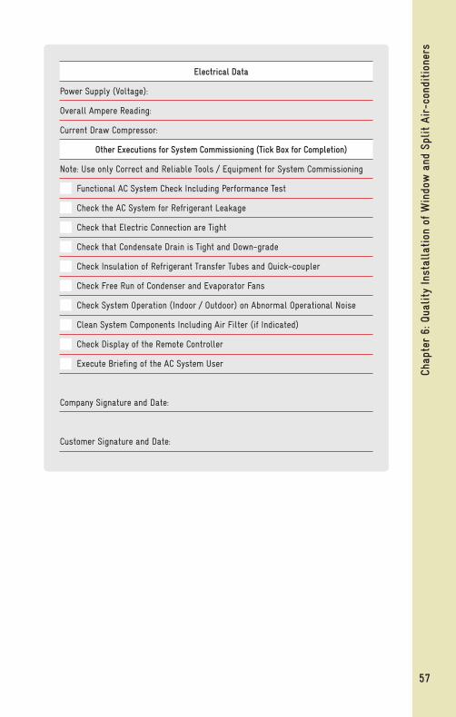
Installation ReportThe technician must fill the installation report as per the format given here below. The technician must learn all the procedures for proper installation of air-conditioners and further acquire the best skills for installation. The report is a proof of good work done and for reference at a later date.
5. Is care taken to avoid any potential complaints from neighbours about vibration and dripping of water? 6. Are electric wires used as per the requirements? 7. Is the earthing wire connected properly to the units? 8. Are line voltage and supply of current as specified? 9. Ensure no leakage of refrigerant. 10. Check operations of the electronic and electrical control panel. 11. Has the temperature of supply and return air been noted? (Difference to be 10-12°C) 12. Does the drain flow out smoothly? 13. Has the customer been educated with regard to benefits, filter cleaning, front grille panel, regular maintenance?
Installation Company’s Name:
Address:
Tel No:
Technician’s Name:
Customer’s Name:
Address:
Tel No:
Installation / Appliance Data:
Model No: Sr. No:
Date of Installation / Repairs: Time:
Refrigerant’s Name/Type: Refrigerant Qty in g:
Suction Pressure: Discharge Pressure:
Air Temp Entering Condenser: Air Temp Leaving Condenser:
Air Temp Entering Evaporator: Air Temp Leaving Evaporator:
Total Length of Copper Tubing: Elevation of Installation:
Continued on next page
57
Chap
ter
6: Q
uality
Ins
tall
atio
n of
Win
dow
and
Spl
it A
ir-c
ondi
tion
ers
Electrical Data
Power Supply (Voltage):
Overall Ampere Reading:
Current Draw Compressor:
Other Executions for System Commissioning (Tick Box for Completion)
Note: Use only Correct and Reliable Tools / Equipment for System Commissioning
Functional AC System Check Including Performance Test
Check the AC System for Refrigerant Leakage
Check that Electric Connection are Tight
Check that Condensate Drain is Tight and Down-grade
Check Insulation of Refrigerant Transfer Tubes and Quick-coupler
Check Free Run of Condenser and Evaporator Fans
Check System Operation (Indoor / Outdoor) on Abnormal Operational Noise
Clean System Components Including Air Filter (if Indicated)
Check Display of the Remote Controller
Execute Briefing of the AC System User
Company Signature and Date:
Customer Signature and Date:

58
Chap
ter
7: A
lter
nati
ve R
efri
gera
nts
to H
CFCs
Chapter 7 Alternative Refrigerants to HCFCs

59
Chap
ter
7: A
lter
nati
ve R
efri
gera
nts
to H
CFCsHydrochlorofluorocarbon (HCFC)
RefrigerantsHydrochlorofluorocarbon (HCFC) refers to the chemical composition of the refrigerant, indicating that the refrigerant molecule is made up of Hydrogen, Chlorine, Fluorine and Carbon.
Currently, HCFC-22 (R22) is used globally as the refrigerant for room air-conditioners. Similar to Chloroflurocarbons (CFCs), HCFCs too contain the chlorine (Cl) atoms that lead to the stratospheric ozone layer depletion. HCFCs have a much shorter atmospheric life than CFCs.
A range of HCFC refrigerants are available and are being used for refrigeration purposes in various appliances.
Select HCFC refrigerants are: HCFC-22, HCFC-123, and HCFC-141b.
HCFC blends are: R-401A and B, R-402A and B, R-405A, R-406A, R-408A, R-409A, R-411A and B, R-414A and B and R-416A.
HCFC refrigerants are extensively used in domestic and commercial appliances. When released into the atmosphere, they not only deplete the ozone layer, but are also classified as Greenhouse Gases (GHGs). It is therefore important to restrict their emissions during the installation and servicing of air-conditioners and refrigeration appliances.
Alternative Refrigerants to HCFCsWhen HCFCs are released in the atmosphere, they not only deplete the ozone layer but contribute to global warming too. When selecting alternatives to HCFCs, in addition to the conventional desirable properties of refrigerants, zero Ozone Depletion Potential (ODP) and low Global Warming Potential (GWP) are very important aspects to be considered. Additionally, safety features must be taken into account.
The American Society of Heating, Refrigerating and Air-conditioning Engineers (ASHRAE) Standard 34, specifies the class for safety of refrigerant and gives a designation to the refrigerant. Refrigerants are categorized for toxicity and flammability.
Toxicity Refrigerants with lower toxicity are categorized as - ‘A’ Refrigerants with higher toxicity are categorized as - ‘B’.

60
Chap
ter
7: A
lter
nati
ve R
efri
gera
nts
to H
CFCs Flammability
Refrigerants with no flammability are categorized as – ‘1’ Refrigerants with lower flammability are categorized as – ‘2’ Refrigerants with higher flammability are categorized as – ‘3’
‘2L’ is used to designate a subset of ‘2’.
For example, Propane and Isobutene are classified as A3 - indicating higher flammability; while Ammonia is classified as B2L indicating toxicity with lower flammability. Carbon Dioxide is classified as A1, indicating lower toxicity and non-flammability.
Alternative refrigerants complying with the above criteria’s are classified into two main groups:
1. Hydrofluorocarbons (HFCs) 2. Hydrocarbons (HCs)
Properties of Alternative RefrigerantsHFCs are non-flammable in most circumstances and they have zero ODP. HFCs are not miscible with mineral oils, which are widely used with CFC, HCFC and HC refrigerants. The lubricants/oils used for HFCs are synthetic polyol ester (POE) type. POEs absorb moisture more rapidly than mineral oil, making the tasks difficult.
Commonly used HFCs are discussed below:
1. R-410A (HFC-32 and HFC -125): HFC is a near azeotropic blend, extensively used in developed countries and in some developing countries, for new systems by OEMs. It requires significant changes in the design, a new compressor, HXs, lubricant, and capillary. R-410A has a GWP of 2088 which is even higher than the GWP of HCFC-22 with 1810.
2. HFC-134a: Extensive redesign with substantial cost increase would be required to match HCFC-22 system. Currently there is no Original Equipment Manufacturer (OEM) in the global market interested in manufacturing HFC-134a appliances. HFC-134a has a GWP of 1430.
3. HFC-161: With Low GWP, its fluid with performance and characteristics comparable to HCFC-22. Official safety classification is not yet established. However thermal stability at high ambient may be an issue.
4. HFC-32: With moderate GWP of 675, it is an alternative to HCFC-22. Due to its thermodynamic characteristics and flammability, some

61
Chap
ter
7: A
lter
nati
ve R
efri
gera
nts
to H
CFCsadaptations are necessary. The efficiency is reported to be comparable,
or better than R-410A appliances.
5. R-407C (HFC-32, HFC -125 and HFC -134a): It is a retrofit blend with relatively high temperature glide. Some of the disadvantages are that it has lower energy efficiency and capacity, requires change in lubricant and material compatibility. It was used in developed countries for early phase-out of HCFC-22, but its use is now decreasing. R-407C has a GWP of 1824.
6. R-417A (HFC-125, HFC-134a, HC-600): It is a retrofit candidate with HFC and HC blend. Disadvantages include fall in capacity and efficiency. This is not yet considered in developed countries.
When blends are used, the composition of the blend in the vapour state will be different from its liquid state. Hence for correct composition, a blend has to be charged in its liquid state.
1. HCs being natural, with zero ODP and very low GWP, are considered to be environment-friendly. HCs do not react with system materials and work well with the currently used mineral oils. However, HCs being flammable by nature, utmost care and safety is essential while using them in commercial refrigeration systems and air-conditioners.
2. HC-290: Retrofitting is possible with similar or marginally lower capacity but with higher Coefficient of Performance (COP), provided safety issues are adequately addressed. Air-conditioners with HC-290 are increasingly in commercial use and also available in India. HC-290 has a low GWP of 3.
Designation of RefrigerantsRefrigerants are designated as: Fully-saturated halogenated compounds, designated with the formula R XYZ Where, R indicates refrigerant X indicates the number of carbon atoms (C) – 1, is omitted if the digit is zero Y-1 indicates the number of hydrogen atoms (H) Z indicates the number of fluorine atoms (F) For example: R12 (CFC12) – (CCl2F2) R22 (HCFC22) - (CHClF2) R134a (HFC134a) – (C2H2F4)

62
Chap
ter
7: A
lter
nati
ve R
efri
gera
nts
to H
CFCs Inorganic refrigerants are designated by ‘7’ followed by their molecular
weight. For carbon dioxide, the designation works out to be R744. Other examples are R717 (ammonia) and R718 (water).
In the case of mixtures, azeotropic mixtures are designated by 500 series e. g. R502 and zeotropic mixtures are designated by 400 series for example, R410A, R407C, and R417A etc.
All hydrocarbons are designated as per formula: RXYZ. For example, propane (C3H8) - R290, n-butane – R600, isobutane - R600a.
Refrigerants like HFC134a which have more than one molecular formulation are designated with lower case letters ‘a’, ‘b’, ‘c’ and so on at the end of the designation. As shown, ‘R’ indicates ‘refrigerant’; 1 is because in the molecular structure of HFC134a, two carbon atoms are present; 3 because of two hydrogen atoms; and 4 because of four fluorine atoms.
Mixtures like R404A are designated by their respective refrigerant numbers and mass proportions. In the case of R404A, R indicates ‘refrigerant’; the first 4 indicates 400 series, 04 indicates chronological numbering designating the components of the mixture, but not the percentage of the constituents; the upper case ‘A’ indicates specific composition i.e. percentage (%) composition. In the case of another composition of the same mixture, it will be denoted by the upper case letter ‘B’ for example, R407A, R407B and R407C.
It has now become customary to indicate refrigerants by the chemical family along with their refrigerant designation number for example, HFC-134a to indicate that R-134a belongs to HFC family. Therefore, refrigerants like R-22, R-161 and R-290 are written as HCFC-22, HFC-161 and HC-290 respectively. However, blends are always written only by their number designation for example, R-410A, although R-410A is a blend of HFCs. This practice also avoids dealing with HFC and HC blends like R-417.

63
Chap
ter
8: G
ood
Serv
ice
Prac
tice
s fo
r Se
rvic
ing
and
Repa
irin
g of
Air
-con
diti
oner
s
Chapter 8 Good Service Practices for Servicing and Repairing of Air-conditioners

64
Chap
ter
8: G
ood
Serv
ice
Prac
tice
s fo
r Se
rvic
ing
and
Repa
irin
g of
Air
-con
diti
oner
s During servicing, recovery of the refrigerant is not a common practice. The refrigerant is often vented out during servicing or repair, and the air-conditioner will be completely recharged. There will be huge savings in refrigerant consumption if proper recovery is carried out by the service technicians. Often, the system also just gets topped up with refrigerant without proper leak detection and will, therefore, continue to leak. Emitting refrigerants into the atmosphere has a negative effect on the environment. While servicing, practices like recovery of refrigerant, leak and pressure testing and replacing inoperative spares are ‘good service practices’ (GSPs) that will increase the operative life of the equipment, as well benefit the environment.
Good Service Practices Ten main steps during servicing or repairing of air-conditioners: 1. Recovering refrigerant from the sealed refrigeration system 2. Repairing/replacing inoperative spare parts 3. Cleaning/polishing and flushing the system 4. Careful brazing and/or flaring of tubes 5. Leak and pressure testing 6. Evacuation and vacuum holding 7. Refrigerant charging 8. Sealing the process tube and closing the valves 9. Routine checking for proper operation 10. Recording the details of work done
1. Recovery of Refrigerant from Sealed Refrigeration SystemThe refrigerant is removed from the system in its present condition and stored in a cylinder. Vapour recovery method or liquid recovery method can be used to remove the refrigerant from the system. The procedure for vapour recovery and liquid recovery is explained under the topic ‘Recovery, Recycling and Reclamation’. For efficient recovery and reduced impact on the environment, 9.52 mm (3/8”) size hoses of short length must be used.
Figure 8.1 Recovery Cylinder
Vapour
Liquid
Yellow Colour
Grey Colour
CutawayView

65
Chap
ter
8: G
ood
Serv
ice
Prac
tice
s fo
r Se
rvic
ing
and
Repa
irin
g of
Air
-con
diti
oner
s2. Repair and/or Replacement of Inoperative SparesThe inoperative spare parts should be replaced with genuine and recommended spares. Each time a system is being repaired, a new strainer and filter should be installed. Install a filter with a molecular sieve. This will desiccate and purify the refrigerant.
3. Cleaning, Polishing and FlushingUpon dismantling the system, all the parts of the system must be cleaned and then polished using emery cloth / paper. The system must be flushed using Oxygen-Free Dry Nitrogen (OFDN - Purity: 99.995%, Dew Point: - 40°C at least) with a two-stage pressure regulator, at a pressure of about 10 bar (150psi).
4. Brazing of Parts or Flaring of Tubes Clean the metal parts adequately and carry out brazing and / or flaring as explained earlier under the chapter ‘Copper Tubing Operations’.
Figure 8.2 Filter
Figure 8.3 Two Stage Pressure Regulator
Figure 8.4 Flaring and Brazing

66
Chap
ter
8: G
ood
Serv
ice
Prac
tice
s fo
r Se
rvic
ing
and
Repa
irin
g of
Air
-con
diti
oner
s 5. Leak and Pressure TestingFor reliability and environment protection, all systems must be pressure and leak tested. For leak-proofing the system, joints must be tested. To keep atmosphere out of the system and clean the tubing of the system, Oxygen-Free Dry Nitrogen (OFDN) should be passed through the sealed system. The system should not be pressurized with pressures that are above the system’s test pressures. (1.1 x operating pressure). For leakages, the system must be checked by leaving it under pressure for 15 minutes (pressure holding). Never start the system when pressurized with OFDN.
Leakage of refrigerant from the system is normally identified using methods like:
Soap solution/bubble method: Soap solution is the most popular, cheapest, and most effective method used by service technicians. Applying soap solution to joints, connections and fittings while the system is running or under a standing pressure of nitrogen and watching for bubbles to appear, helps to identify leak points.
Electronic detector: Electronic refrigerant detectors contain elements sensitive to a particular chemical component in a refrigerant. The detector has a pump that can suck in the gas and air mixture. An audible “ticking” signal and/or increased frequency/intensity of the flashing of the lamp occurs as the sensor analyses higher concentrations of refrigerant, indicating the source and location of the leak.
The most common locations of leakages in joints are at:
1. Flare connections/nuts 2. Service valve: O-rings, access fitting, mounting 3. Cracked brazed joint in tubing 4. Deteriorated evaporator and / or condenser end bends 5. Tubes rubbing with each other or with other materials
Figure 8.5 Leak and Pressure Testing
Figure 8.6 Electronic Refrigerant Detector

67
Chap
ter
8: G
ood
Serv
ice
Prac
tice
s fo
r Se
rvic
ing
and
Repa
irin
g of
Air
-con
diti
oner
sWhen refrigerant leaks out, it increases the cost of repairing and servicing. It also has harmful effects on the environment. The efficiency of the system drops and power consumption increases. Therefore, CO2 consumption increases and there is a greater impact on environment or climate change. Hence, care must be taken to avoid refrigerant leakages.
6. Evacuation and Vacuum HoldingEvacuation is a process by which pressure in the sealed system is reduced, causing moisture to boil off into vapor. It removes air, moisture and other non-condensable gases from the system. Frozen moisture in the system may lead to one of the following problems:
• Choked capillary tube, metering device and strainers • Choked filter driers • Reduced system effectiveness and efficiency
To speed up evacuation, large valve port/hoses (9.52 mm or 3/8”) must be used. To measure the desired level of evacuation, connect the micron gauge to the manifold.
Before charging refrigerant to the system, if possible, evacuate the system from both high and low pressure sides, using a double-stage rotary vacuum pump (100 lpm and blank off 20 microns). Only two-stage rotary vacuum pumps are able to pull the vacuum to the required level.
The ideal vacuum should be about 0.666 mbar (500 micron) or higher. The compressor of the system must not be operated while the system is in a vacuum. On achieving the vacuum (500 microns), disconnect the pump and allow the system pressure/vacuum to settle down for 5-7 minutes. (During vacuum holding of 5-7 minutes, pressure should not rise above 1500 microns). If the evacuation is not achieved to the desired level of 500 microns, the effect of the presence of air and moisture in the compressor could lead to compressor seizing or failure due to excessive wear of compressor moving parts or motor overheating and burn-out.
(Please note that water can boil even at lower temperatures, if the pressure is reduced by pulling vacuum. So pulling deep vacuum will help in removing the above-mentioned undesired materials from the system.)
Figure 8.7 Vacuum Pump

68
Chap
ter
8: G
ood
Serv
ice
Prac
tice
s fo
r Se
rvic
ing
and
Repa
irin
g of
Air
-con
diti
oner
s
7. Refrigerant ChargingFor better performance of the air-conditioner, charging with accurate quantity of refrigerant is important. Charge always in a well evacuated system. Sweep charge or charge by feel, is not recommended. Charging should be done slowly and gradually, so that no liquid goes into
Temperature in Celsius Vacuum in Microns
100.00 7,59,968
96.11 5,35,000
90.00 5,25,526
80.00 3,55,092
70.00 2,33,680
60.00 1,49,352
50.00 92,456
40.00 55,118
30.00 31,750
26.67 25,400
24.44 22,860
22.22 20,320
20.56 17,780
17.78 15,240
15.00 12,700
11.67 10,160
07.22 7,620
00.00 4,572
-06.11 2,540
-14.44 1,270
-31.11 254
Table 8.1 Water Boiling Points V/s Vacuum

69
Chap
ter
8: G
ood
Serv
ice
Prac
tice
s fo
r Se
rvic
ing
and
Repa
irin
g of
Air
-con
diti
oner
sthe compressor. Since there is no effect of atmosphere (pressure / temperature) on mass or weight of the refrigerant, weight system must be deployed for measuring the amount of refrigerant while gas charging. A digital weighing scale/balance for accurate quantity of charge must be used. This is a must for efficient functioning of the air-conditioner and it is a GSP. In case the system gets over charged, the excess charge of HCFC-22 should not be vented out into the atmosphere, but recovered. Refrigerant should enter the compressor only in a vapour state. After 5 minutes of refrigerant charging, pressures and temperatures of refrigerant must be checked. High or low pressures and temperatures indicate that the system is overcharged or undercharged. Undercharged systems are less efficient, have higher running costs and might not be able to meet the load. Overcharged systems have greater potential of leakage. In extreme cases, overcharging will increase head pressure and reduce performance and efficiency. After disconnection of gauges and hoses, a leak test must be carried out.
8. Tube Sealing Process / Closing ValveAfter correct charging of refrigerant, the charging tube should be sealed or the valve should be closed properly. Follow these steps:
1. Crimp/pinch the tube to be sealed at two places 2. The pinching tool must not be removed until the tube is sealed 3. Braze or seal the tube 4. Remove the pinching and / or crimping tool 5. Final leak test must be done
Figure 8.9 Charging Unit and Weighing Scale

70
Chap
ter
8: G
ood
Serv
ice
Prac
tice
s fo
r Se
rvic
ing
and
Repa
irin
g of
Air
-con
diti
oner
s OR 1. Close the three-way service valve properly 2. Check for leaks 3. Put the lock-nut 4. Final leak test must be done
9. Routine Check-up for Proper FunctioningAs part of a routine check-up, measure temperatures of supply and return air after 20 minutes. Measure the current drawn by the air-conditioner. Keep a record on the job cards. Label the system and leave it in order. Record all observations.
10. Record Details of Work Done / Report Writing
Figure 8.10 Recording Observations
Suggested job card for repairing of system:
Pre- and Post- Details of Refrigeration System Repairs
Customer & Product Details Post Repairs
Customer Voltage V
Address Current I
WAC/SAC Sr No. Low Pressure
Model No. High Pressure
Type of Refrigerant Gas Leak Jt # Repaired
Chargeable / Under Warranty / AMC Vacuum Achieved
Diagnosis – Pre Repairs G L Jt # Reconfirmed
Voltage V New Compr #
Current I Parts Replaced
Low Pressure
High Pressure Charged Refrigerant Quantity
Gas Leak Jt # # of Leak Tests
Old Compr. # Supply & Return air Temp
Original Refrigerant Charge Qty Misc. Info.
Tech Name or Code # Tech Name or Code #

71
Chap
ter
8: G
ood
Serv
ice
Prac
tice
s fo
r Se
rvic
ing
and
Repa
irin
g of
Air
-con
diti
oner
s
General Guidelines for Good Service Practices:1. Work in a clean, well-ventilated and dry area 2. Wear gloves, goggles and apron or clothing which covers the body when working 3. Ensure the appliance is disconnected from the mains electric supply before carrying out any work on it 4. Take care while opening the system as the pressure inside the system is generally higher than atmospheric pressure 5. Keep systems and components sealed. Repair and/or replace components as necessary 6. Change the filter drier whenever the system is opened for maintenance or if it is contaminated 7. Liquid refrigerant causes frostbite if it comes into contact with human skin. For protection, wear personal protective equipment (PPE) 8. The refrigerant in the air-conditioner may be contaminated with acids. Ensure it does not come into contact with the skin 9. The compressor oil may also be acidic, so wear gloves and goggles when removing and/or repairing a faulty compressor 10. Pressure and leak test systems using Oxygen-Free Dry Nitrogen (OFDN) 11. Always use a two-stage pressure regulator (up to 50 bar) when using nitrogen 12. Ensure that all hoses are free from cracks and have adequate strength to withstand high pressures 13. Evacuate the system from both high and low sides using a two- stage Rotary Vane High Vacuum pump of blank-off pressure equal to 20 microns of Hg 14. Charge the system with correct quantity of good quality refrigerant 15. Seal the charging point by brazing and then test for leakage 16. Label the air-conditioner correctly with information of the refrigerant used 17. Make sure the refrigerant cylinder/can valves are in good condition and are capped when not in use 18. Do not modify cylinder/can or valves 19. Do not re-fill disposable cylinders/cans 20. Store refrigerant cylinders in an upright position in a well- ventilated area, away from heat sources and risk of fire

72
Chap
ter
9: R
ecov
ery,
Rec
ycling
and
Rec
lam
atio
n of
Ref
rige
rant
s
Chapter 9 Recovery, Recycling and Reclamation of Refrigerants
73
Chap
ter
9: R
ecov
ery,
Rec
ycling
and
Rec
lam
atio
n of
Ref
rige
rant
sMany countries have passed legislation preventing the use of chemicals / refrigerants that affect the ozone layer. The need for preventing release of refrigerants into the atmosphere has resulted in new procedures. Various methods for recovering, recycling and reclaiming these refrigerants have been developed.
DefinitionsRecover: To remove refrigerant, in any condition, from a system and store it in an external container.
Recycle: To extract refrigerant from an appliance and clean it using oil separation and single or multiple passes through filter driers. These devices reduce moisture, acidity and particulate matter. Recycling normally takes place in the field or at the site of the job.
Reclaim: To reprocess used refrigerant, typically by distillation, to the specifications close to the virgin refrigerant. Reclamation removes contaminants such as water, chloride, acidity and residue with high boiling point, particulates/solids, non-condensable gases and impurities, including other refrigerants. Chemical analysis of the refrigerant will be required to determine that appropriate specifications are met. The identification of contaminants and required chemical analysis are specified by national or international standards. Reclamation is mostly done at a reprocessing or manufacturing facility.
General Safety Tips for Handling RefrigerantsTransfer of any type of refrigerants into storage cylinders, requires careful handling of the refrigerants. This requires the technician to work according to strict safety regulations.
1. Material Specification Data Sheet (MSDS) issued by refrigerant manufacturers containing safety advice for the handling of refrigerants, must be carefully read. 2. The cylinder must be filled to only 80% of its total capacity. 3. Pressured and liquefied refrigerant may rapidly create dangerous situations. If liquid gas comes in contact with the human body viz. skin, eyes and / or respiratory system, it can cause severe injury. Hence, when at work, personal protective equipment (PPE) must always be used. 4. The work place should be a ‘No Smoking’ zone and well- ventilated. Refrigerants are odourless, invisible and heavier than air. They reduce the content of oxygen in the air. Breathing

74
Chap
ter
9: R
ecov
ery,
Rec
ycling
and
Rec
lam
atio
n of
Ref
rige
rant
s in refrigerants may not be noticed, but can lead to death. 5. Cylinders filled with refrigerant must not be stored at a high ambient temperature and/or exposed to the sun. 6. The working pressure of each cylinder must not be exceeded. The label on the cylinder must be checked for information about the pressure. 7. Only clean, dry cylinders, free from contamination viz. by oil, acid, moisture, must be used. 8. A weighing scale must always be used to check the amount of refrigerant in the cylinder. 9. Different refrigerants and refrigerants with different grades must not be mixed and stored in the same cylinder. 10. Visually check each cylinder before use and make sure all cylinders are regularly pressure tested. 11. Recovery cylinders have a specific indication depending on the country (For example, yellow mark in the United States; special green colour in France) in order not to be confused with the refrigerant containers.
Recovery of RefrigerantRemoving refrigerant from a refrigeration system in any condition and storing it in an external cylinder is known as recovery. When the system is being repaired, the refrigerant needs to be removed from the system. Recovery can be done by having proper equipment for the process. Recovery equipment that can recover refrigerants with high pressure must be selected.
Safety is always a concern when recovering refrigerant. Manifold gauges, safety glasses/goggles, gloves, a refrigerant recovery cylinder (other than normal), a weighing scale, an approved refrigerant recovery unit, and suitable hoses will be required to recover refrigerant from the system. For safety, personal protective equipment (PPE) must always be worn. To avoid the formation of phosgene gas, refrigerant should not be recovered near an open flame. A weighing scale must be used to avoid overfilling of the recovery cylinder. Overfilling can cause the cylinder to rupture and severely damage the equipment.
Recovery of refrigerants is similar to evacuating a system using the vacuum pump. There are three different recovery methods: Vapour recovery method (most common); the Liquid recovery method; and the Push-Pull method. A filter-dryer or particulate filter must be used on the refrigerant recovery unit as acid and particulate matter may lead to damage of the refrigerant recovery system.
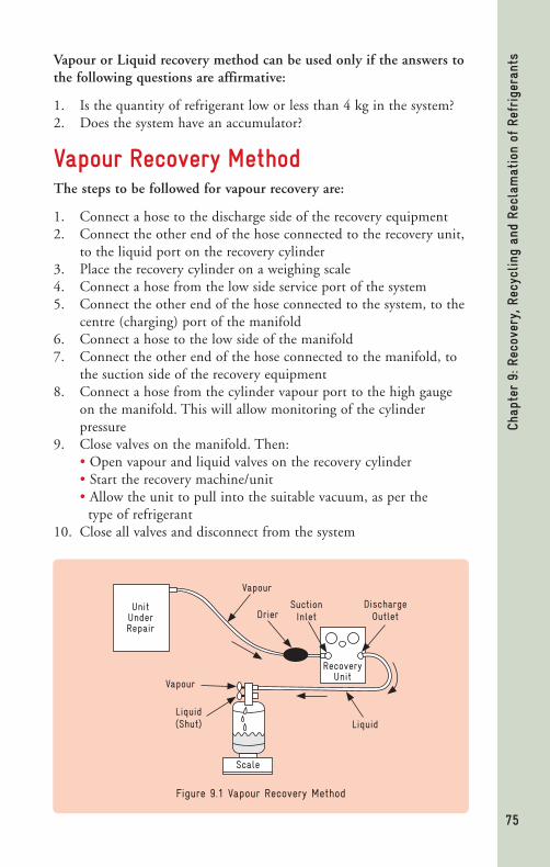
75
Chap
ter
9: R
ecov
ery,
Rec
ycling
and
Rec
lam
atio
n of
Ref
rige
rant
sVapour or Liquid recovery method can be used only if the answers to the following questions are affirmative:
1. Is the quantity of refrigerant low or less than 4 kg in the system? 2. Does the system have an accumulator?
Vapour Recovery MethodThe steps to be followed for vapour recovery are:
1. Connect a hose to the discharge side of the recovery equipment 2. Connect the other end of the hose connected to the recovery unit, to the liquid port on the recovery cylinder 3. Place the recovery cylinder on a weighing scale 4. Connect a hose from the low side service port of the system 5. Connect the other end of the hose connected to the system, to the centre (charging) port of the manifold 6. Connect a hose to the low side of the manifold 7. Connect the other end of the hose connected to the manifold, to the suction side of the recovery equipment 8. Connect a hose from the cylinder vapour port to the high gauge on the manifold. This will allow monitoring of the cylinder pressure 9. Close valves on the manifold. Then: • Open vapour and liquid valves on the recovery cylinder • Start the recovery machine/unit • Allow the unit to pull into the suitable vacuum, as per the type of refrigerant 10. Close all valves and disconnect from the system
Figure 9.1 Vapour Recovery Method
LiquidLiquid(Shut)
Vapour
Vapour
DrierSuctionInlet
DischargeOutlet
RecoveryUnit
Unit Under Repair
Scale

76
Chap
ter
9: R
ecov
ery,
Rec
ycling
and
Rec
lam
atio
n of
Ref
rige
rant
s
Liquid Recovery MethodWith the use of oil-less compressors and constant pressure regulator valves, the Liquid recovery method is becoming the recovery method of choice for many manufacturers of recovery equipment.
The steps to be followed for liquid recovery are:
1. Connect a hose to the low side access point of the recovery unit compressor discharge valve. 2. A second hose is then connected from the recovery unit compressor suction valve, through a filter drier, to a two-valve external storage cylinder. 3. A third hose is connected from the high side access point (liquid valve at the receiver) to the two-valve external storage cylinder. 4. Turn on the recovery machine/unit. Here, the compressor pumps refrigerant vapour from the external storage cylinder into the refrigeration system, which pressurizes it. The difference in pressure between the system and the external storage cylinder forces the liquid refrigerant from the system into the external cylinder. 5. Once the liquid refrigerant is removed from the system, the remaining vapour refrigerant is removed using the vapour recovery method as explained earlier.
Figure 9.2 Liquid Recovery Method
Scale
RecoveryUnit
VapourSide
Liquid
LiquidSide Sight
Glass
DischargeOutlet
SuctionInlet
Vapour Drier
VapourLiquid
052Unit Under Repair

77
Chap
ter
9: R
ecov
ery,
Rec
ycling
and
Rec
lam
atio
n of
Ref
rige
rant
s
Push-Pull Recovery MethodThe Push-Pull method can be used only after the design of the system being serviced or repaired is checked.
The steps to be followed for Push-Pull recovery are:
1. Connect a hose from the vapour port of the cylinder to the centre port of the manifold 2. Connect a hose from the low side of the manifold to the suction side of the refrigerant recovery unit 3. Connect a low-loss hose from the discharge side of the recovery unit, to the low side service port of the manifold 4. Connect the hose from the high side service port of the manifold to the cylinder liquid valve 5. Place the cylinder on a weighing scale 6. Open the valves of the recovery cylinder 7. Start the refrigerant recovery machine 8. Open the low side valve on the manifold 9. Monitor the weighing scale 10. Switch over the unit to vapour recovery once the weighing scale stops picking up weight
On recovering the refrigerant using any one of the above methods, label the recovery cylinder indicating a) when it was recovered; b) type of refrigerant; and c) its weight.
RecyclingThe process of recycling consists of cleaning the refrigerant for reuse by oil separation and single or multiple passes through filter driers which reduce moisture, acidity etc.
In the past, refrigerant was typically vented into the atmosphere, but currently the recycling equipment enables reuse of refrigerant. Refrigerant removed from a system cannot be reused in as-it-is form; it needs to be cleaned for any contamination.
Recycling machines reduce the contaminants through oil separation and filtration. Normally, recycling of refrigerants is carried out using equipment that does both recovery and recycling of the refrigerant.
Recycling machines use either the single pass or multiple pass method of recycling. In the single pass method, refrigerant passes through a filter drier and/or distiller. It makes only one pass through the recycling process to a storage cylinder.

78
Chap
ter
9: R
ecov
ery,
Rec
ycling
and
Rec
lam
atio
n of
Ref
rige
rant
s
The multiple pass method recirculates refrigerant through the filter drier many times and after a period of time or number of cycles, the refrigerant is transferred to a storage cylinder.
Figure 9.3 Single Pass Recovery Equipment
ManifoldPre-Filter
AC Unit
RecoveryUnit
Condenser
System Drier Filter
Recovery Cylinder
Purge Unit
Oil Separator Accumulator Compressor
Oil Separator
Oil DrainOil Drain FilterDrier
Oil Return
Figure 9.4 Multiple Pass Recovery Equipment
Moisture Indicator
Liquid Pump
Recycle Solenoid
ManifoldPre-Filter
AC Unit
RecoveryUnit
Filter Drier System
Receiver & Purge Unit
Recovery Cylinder
Condenser
Oil Separator Accumulator Compressor
Oil Separator
Oil DrainOil Drain FilterDrier Oi
l Re
turn
RECYCLE LOOP

79
Chap
ter
9: R
ecov
ery,
Rec
ycling
and
Rec
lam
atio
n of
Ref
rige
rant
s
Reclamation Reclamation is a process when a refrigerant is processed equal to virgin refrigerant. The refrigerants reclaimed shall conform to ARI Standard 700–1993, Specifications for Fluorocarbon and Other Refrigerants.
Most types of reclaiming equipment operate on the same process, where the used or contaminated refrigerant enters the reclamation unit in vapour or liquid state. It is heated (distillation) till the pure refrigerant vapour is separated from the contaminated refrigerant. The refrigerant then enters a large, exclusive separator chamber where the velocity radically drops. This allows the high temperature vapour to rise. In the separator chamber, contaminants like copper debris, carbon, oil and acid settle at the bottom of the separator.
These contaminants can be removed during the ‘oil out’ or ‘drain’ operation. The distilled refrigerant in the vapour form from the separator enters into an air-cooled condenser. Here, it gets converted to a liquid form. The liquid refrigerant passes through a filter drier and then into a storage chamber where the purified refrigerant is cooled to a temperature of 3°C - 4°C by an evaporator assembly.

80
Chap
ter
10: S
afet
y an
d M
aint
enan
ce
Chapter 10Safety and MaintenanceChapter 10Safety and Maintenance

81
Chap
ter
10: S
afet
y an
d M
aint
enan
ceThe term ‘safety’ is applicable to any refrigeration or air-conditioning activity. It may apply to safety of the operator/technician/customer, safety of the tools and equipment. Technicians using hand and power tools are exposed to hazards like falling, flying, abrasive and splashing objects/materials, or harmful dusts, fumes, mists, vapours/gases or lubricants. Personal protective equipment must be worn by the technician when at work, to protect him from these hazards.
There is no exception to the rule that ‘The safe way is the right way.’
Work must be done by properly trained personnel equipped with the tools and equipment in good condition and of good quality.
Maintenance of tools and equipment is equally important as it increases the availability of a tool and equipment when required and keeps the same in working order. Further maintenance helps reduce undesired expenses.
SafetyPersonal SafetyWhen at work, the technician must protect himself from any injuries. PPE viz. safety glasses, protective shoes, gloves and safety belt should be worn. A proper dress code must be observed. Wear a lab coat. Never wear loose jewelry – it may come in contact with the electrical terminals or wires causing electrical shocks. Put up posters mentioning safety rules and guidelines at the work place as safety reminders.
Safety of Tools and Equipment 1. These must be maintained and inspected regularly. 2. The right tools must be used for doing the job. 3. These must be operated according to the instructions of the manufacturers. 4. Hacksaw blades, knives, drill bits or other tools must be directed away from walkways and other technicians working in close
Figure 10.1 Personal Protective Equipment

82
Chap
ter
10: S
afet
y an
d M
aint
enan
ce proximity. Dull tools can be more hazardous than sharp ones. 5. Technicians operating the tools and equipment have personal responsibility of using them carefully by learning the appropriate skills.
Safety While Using Power Tools1. Disconnect tools when not in use, before servicing and cleaning and when changing accessories. 2. People who are not involved with the ongoing work should be kept away from the worksite. 3. Secure work with clamps or a vise, freeing both hands to operate the tool. 4. Do not keep your hand on the tool switch while carrying the plugged-in tool. 5. Keep tools sharp and clean. 6. Remove damaged electric tools and tag them: ‘Do Not Use’. 7. Do not carry or pull portable tools by the cord. 8. Do not use electric cords to hoist or lower tools. 9. Do not pull the cord or hose to disconnect the tool. 10. Keep cords and hoses away from heat, oil and sharp edges. 11. Replace damaged cords immediately.
Electrical Safety1. The most common reasons for failure in the working of air conditioners are faults in electrical circuits or items. 2. The electrical wires/cables in an air-conditioning unit must be grounded without fail. This protects from electric shock by allowing current to by-pass the human body. 3. Power tools and extension cords normally have three prongs connected to the electrical wires. These prongs should never be cut or removed, leaving the electrical wire naked. 4. Technicians must be well aware of the potential hazards that exist and the precautions to be taken to reduce the risk of accidents.
Fire SafetyA fire extinguisher should be kept /carried to the workplace / place of servicing and / or installation site as a safety measure in case of accidental fire. Fire extinguishers are classified in three groups, based on the cause of fire that requires to be extinguished:
Class A fire extinguishers are designed for use on fire occurring from burning wood, paper, or other ordinary combustibles.
Class B fire extinguishers are designed for use on fire due to flammable liquids like grease, petrol or oil.

83
Chap
ter
10: S
afet
y an
d M
aint
enan
ceClass C fire extinguishers are designed for use on electrical fires.
Use of ABC powder-type fire extinguisher is ideal.
Safety While Working on Air-conditionersWhile servicing and / or installing air-conditioners, a few basic safety measures should be taken:
1. Servicing manual and / or training handbook must be kept handy for reference if required. 2. Only recommended spare-parts must be used. 3. Always verify for correct operating pressures of the refrigerants. 4. Calibrated pressure gauges must be used. 5. Charge only through low side of the system. 6. Ensure that the entire refrigerant has been removed from the system.
Handling & Storage of Refrigerant CylindersCylinders filled with the refrigerant have to be handled with utmost care. They have to be stored too as per the guidelines, viz:
1. Gas cylinders should be stored in a covered area where the temperature is below 50°C.
Figure 10.2 Fire Extinguisher and Symbols
Symbols found on Fire Extinguishers and what they mean
Water Foam Spray
ABCPowder
Carbondioxide
Wet Chemical
Wood, Paper and Textiles
Flammable Liquids
Flammable Gas
Electrical Contact
Cooking Oils & Fats
A
B
C
F

84
Chap
ter
10: S
afet
y an
d M
aint
enan
ce 2. Cylinders must be kept away from sources of ignition, including static discharges. 3. The work area and where the cylinders are stored, should be a ‘no smoking’ zone. 4. Gas alarm and water sprinklers must be installed in the refrigerant storage area and specifically for flammable refrigerants. 5. Certified stickers on the cylinders must not be removed or destroyed When the cylinder is not in use, ensure that the cap is closed. 6. Gas cylinders must be stored and transported only in an upright position. 7. During transportation, gas cylinders should not be thrown or dropped. All main electrical power controls should be installed outside the work area. 8. The recovery cylinders must be filled to only 80% of their total capacity.
First Aid for Injuries to TechniciansFor injuries due to refrigerant spilling over on the skin of the technician, cover the area with a warm and dry cover, to avoid frostbite. Then obtain professional medical help. In case of asphyxiation, opt for cardiopulmonary recovery.
If there is a chemical burn, remove clothing on or near the burn area and wash the affected area with normal water. If the eyes are hurt, flush them continuously for 15-20 minutes.
If the technician has had an electrical shock, others around should not touch him until the power supply is disconnected. Then quickly treat him with first aid.
Figure 10.3 Storage of Refrigerant Cylinders
85
Chap
ter
10: S
afet
y an
d M
aint
enan
ceQuality Maintenance of Select Tools and Equipment ‘Maintenance’ means all actions necessary for retaining an item, tool or equipment in a serviceable condition, or restoring it to a serviceable condition. This includes servicing, repair, modification, overhaul, inspection and condition verification. Maintenance increases the availability of a system or tool and equipment when required and keeps the same in working order.
Planned or scheduled and preventive maintenance is necessary in the servicing of air-conditioners. Maintenance is a part of preserving air-conditioners for a long time and for better performance. It is recommended that the dates on which regular maintenance is to be carried out, should be fixed for a year.
As explained earlier, it includes scheduled inspections, lubrication, overhauling of equipment and tools and changing oils/lubricants, as also appliances.
Good and timely maintenance of tools and equipment ensures assured proper working of the same when required.
1. Routine maintenance is a must as electro-mechanical tools/ equipment are used by RAC technicians. 2. Scheduled planned maintenance actions aim at avoidance of breakdowns and unexpected failures during servicing or repairing. 3. The basic goal of maintenance is to prevent the failure of tools and equipment before it actually occurs. 4. Maintenance is designed to preserve and enhance reliability of tools and equipment by replacing worn components before they actually fail. 5. It helps reliability, safety and productivity as also avoids waste, disruption, accidents and inconvenience.
Vacuum PumpThe oil level must be checked through the oil sight glass before each use. The main cause of vacuum pump failure is low oil level and/or contaminated oil. Oil in the vacuum pump should be regularly changed to maintain its ultimate pressure, specified to evacuate to the vacuum required for the refrigerants.
As per the vacuum pump supplier’s instructions, change the oil immediately after the pump is used for about 100 hours or 200 system

86
Chap
ter
10: S
afet
y an
d M
aint
enan
ce repairs, or even earlier if the refrigerant has been removed from a highly contaminated system. Use only manufacturer-recommended good quality vacuum pump oil.
Always disconnect the vacuum pump from the electrical source before performing any maintenance. Get the pressures measured with a calibrated vacuum gauge or micron gauge. Replace the 3/8” filter/drier.
Maintain a record of maintenance jobs done.
Check electrical wires and plugs for wear and tear or damage each month. If damage or excessive wear and tear is found, replace them.
Steps for changing vacuum pump oil:
1. Operate the vacuum pump to heat up the vacuum pump oil. 2. Turn the vacuum pump switch off and disconnect the electrical cord plug from the electrical outlet. 3. Place the vacuum pump on a level surface. 4. Unscrew and remove the oil plug from the bottom of the pump housing to let the oil drain from the pump completely. 5. Refit the drain plug back into the pump housing. 6. Remove the oil fill plug at the top of the pump housing. 7. Add oil as noted on specification/amount of recommended vacuum pump oil, to raise the oil level to the full oil level marks of the oil sight glass. 8. Refit the oil fill plug. 9. Operate the vacuum pump for a short period of time. 10. Check the oil level through the oil sight glass.
Micron GaugeThe micron gauge is very crucial in evacuation or system repairs. It must be maintained at its best. Regularly check its sensor and keep it safe. Read all instructions for operation and regular maintenance, including calibration, etc. This being delicate equipment, do not tamper with it on your own but contact the supplier or manufacturer for assistance.
Make a note in your diary or mobile phone about the details of the repair for future reference. The record of maintenance has to be maintained.
Manifold Gauge and Charging HosesKeep the manifold gauge set clean for better and safer performance and

87
Chap
ter
10: S
afet
y an
d M
aint
enan
cemaintain it regularly. Before using any gauge, any part that appears damaged should be carefully checked to determine that it will operate properly and perform its intended function. If there is any doubt, do not operate the gauge. The gauge must not be operated if under the influence of alcohol or drugs or if one is tired.
Get the hoses inspected periodically. Do not disconnect any pressurized hose.
When servicing, use only identical replacement parts. Any safety, service and maintenance procedures should be performed regularly by a qualified technician.
Leak DetectorMake sure and use the appropriate leak detector designed to detect the refrigerant you are working on. Care must be taken of their sensors. Avoid contact of the sensors with any of the materials or any type of contamination. Keep a 2mm gap between the sensor of the leak detector and the joint under testing. Keep it in a dust-free area.
Refrigerant Charging Station, Charging Hoses and GaugesHCFC refrigerant can be charged into a system in the same way as CFCs and HCs are charged and generally the same equipment can be used. However, to avoid cross-contamination in equipment, it is better to flush the equipment and its attachments with Oxygen-Free Dry Nitrogen (OFDN).
The same set of charging hoses may be used for HCFCs and HCs, however for HFCs use a separate suitable set of hoses due to possible cross-contamination and higher pressures. For HC, gauges are available with suitable calibration and hence, use only the recommended ones.
Recovery UnitAny assembled recovery unit may not be as reliable as commercially-manufactured units.
The compressor can fail and will need replacement if the machine is
Figure 10.4 Electronic Refrigerant Detector

88
Chap
ter
10: S
afet
y an
d M
aint
enan
ce used on a regular and extensive basis. Therefore, it is recommended that a spare compressor is kept ready for this purpose.
1. A filter dryer must always be used between the recovery machine and its inlet hose. 2. Special care should be taken when recovering from a ‘burnt-out’ system. Use two high acid capacity filters in series. When recovery of the refrigerant from the system is complete, flush it with a small amount of OFDN or clean refrigerant and lubricant to purge off any foreign materials left inside. 3. Always remove the refrigerant into the external storage cylinder. Liquid refrigerant left in the condenser may expand, causing damage to the components. 4. Before beginning any type of maintenance work, ensure that the power supply is disconnected. 5. If the unit is to be stored or not used for a long time, it is recommended that it be completely evacuated of any residual refrigerant and purged with OFDN.
Preventive Maintenance of Room Air-conditionersRegular maintenance of room air-conditioners will improve their life, performance, reliability and safety. Maintenance is necessary to be carried out by both customer and technical professionals viz. service technicians. Given below are the tasks to be performed by the customer and the technicians.
Maintenance by Customer1. Change and/or clean the primary filter every two months. If the unit is equipped with a plasma indoor air quality filter, clean it when the reminder light illuminates. 2. Vacuum dust from the indoor evaporator coil and wipe away built-up dirt. Leave heavier, stubborn dirt deposits or mould accumulation for cleaning by a professional technician. 3. Clean the condensate drain pan, drain and verify that the drain is open. If there’s evidence of mould or other bacterial growth, let a technician handle it. 4. Cut weeds or other encroaching vegetation from around the outdoor condenser to allow two feet of free space on all sides for airflow.
Maintenance by Technician1. Inspect and clean the evaporator coil.

89
Chap
ter
10: S
afet
y an
d M
aint
enan
ce2. Check the balance of the blower and fan wheel and verify there is sufficient airflow. 3. Inspect the condensate drain system for algae and treat with algaecide if necessary. 4. Check the refrigerant charge and top up as necessary. If the level is significantly low, perform leak detection procedures. 5. Clean the condenser coil and clear out debris such as grass clippings and leaves. 6. Verify electrical connections at the outdoor unit and weatherproof with non-conductive coating. 7. Lubricate the condenser fan and adjust belt tension, if required. 8. Check thermostat operation and calibrate, if necessary. 9. The technician must clean the evaporator coil, condensate pan and filters. Similarly, he must clean and flush the brazing torch with its tip.
Regular Preventive Maintenance of Room Air-conditioners 1. Check voltage, current and earthing. 2. Inspect for refrigerant/lubricant/oil leaks and proper levels. 3. Confirm that the condenser coil is free from debris. 4. Straighten any bent heat exchanger fins on the condenser coil. 5. Examine suction pipe insulation and replace, if needed. 6. If the AC is of very old design, lubricate the fan motors/bearings. 7. Check fan/blower blades/fins for damage and cleanliness. 8. Ensure proper condition of 2- and 3-way service valves, with caps. 9. Check all wiring, electrical connections. 10. Test controls/thermostat/PCB for proper functioning. 11. Assess air filters for proper size and cleanliness. 12. Confirm that the evaporator coil is free from dust. 13. Check condensate pan and drain for cleanliness. 14. Confirm no leakages from RAC products, tools/equipment. 15. Record all the work done during preventive maintenance. Refer to the sample overleaf.
Turn overleaf for sample work record form

90
Chap
ter
10: S
afet
y an
d M
aint
enan
ce
Table 10.1 Sample Work Record Form
Contents
Dry/Wet Service
Observation Checked and
Explained
Yes No
Customer & Product Details:
Customer:
Address:
WAC/SAC Sr. No:
Model No:
Other Information:
Chargeable / Under Warranty / Under AMC:
1. Check for the working of air-conditioner before start of servicing
2. Measure voltage, current, earthing, in & out air temperature and update the same to the customer. Before servicing air-conditioner, switch-off the air-conditioner.
3. Clean AC using air blower - evaporator and condenser / water wash
4. Cleaning and washing of air filter and front grille
5. Oiling of fan/blower motor (in case of old models only)
6. Check wire connections at the terminals of compressor, capacitor and other electrical parts / connections of PCB, etc.
7. Start the air-conditioner to check working of air-conditioner after servicing
8. Check the cut-in and cut-out cycling of compressor with the help of thermostat
9. Measure voltage, current and earthing after completion of servicing
10. Measure grille intake and return air temperature after 25 minutes of run
11. Detailing to the customer about the work done and improved performance of AC
12. Educate customers - tips for better performance including energy saving

91
Not
esNotes

92
Not
es Notes


HCFC Phase-Out Management Plan (HPMP) for Service Sector in India: The Government of India has planned to reduce consumption of HCFC in the servicing sector during Phase 1 (2012 – 2014) in order to meet its compliance targets in 2013 (freeze) and 2015 (10% reduction) in line with the accelerated phase-out schedule of the Montreal Protocol. In the servicing sector HCFC-123, HCFC-124, HCFC-142b
and HCFC-22 are consumed, however, during Phase I only the consumption of HCFC-22 will be addressed. Awareness raising, early adoption of better servicing practices and recovery would have an immediate phase-out impact and could significantly reduce the consumption of HCFC in the country
The Refrigeration and Air Conditioning (RAC) servicing sector contributes to a large extent to the consumption of HCFCs, in particular in the room air-conditioner segment. GIZ-Proklima on behalf of the Government of Germany and in close co-operation with the Ozone Cell in the Ministry of Environment and Forests will implement phase-out activities in the Indian RAC servicing sector. The consumption will be reduced mainly through training on better servicing practices and leak prevention but service technicians also need to be prepared on the introduction of alternatives like HC-290, HFC-410a and HFC-32. There are already 15 training partners in the country which will reach out to train as many technicians as possible and to address all the identified sub-sectors in metros and towns all over India.
Lead Implementing Agency for Service Sector: Deutsche Gesellschaft für Internationale Zusammenarbeit (GIZ) GmbH B-5/2, Safdarjung Enclave New Delhi - 110029, India Tel: +91-11-49495353 Web: www.giz.de/india