Embed Size (px)
Citation preview

GOHFNWOLF_PG._ATTORNEYS AT LAW RACHEL A. SCHWARTZMAN
Please Reply To: BridgeportWriter's Direct Dial: X203) 337-4110E-Mail: rschwartzman(~cohenandwolf.com
Attorney Melanie BachmanActing Executive DirectorConnecticut Siting CouncilTen Franklin SquareNew Britain, CT 06501
Re: Notice of Exempt ModificationSBAfT-Mobile co-locationSite ID CT11346C160 Deer Run Road, Wilton, CT
Dear Attorney Bachman:
November 26, 2014
This office represents T-Mobile Northeast LLC ("T-Mobile") and has been retained to fileexempt modification filings with the Connecticut Siting Council on its behalf.
In this case, SBA owns the existing lattice telecommunications tower and related facilityat 160 Deer Run Road, Wilton, CT (41.239166/-73.47111100). T-Mobile intends to replace three(3) existing antennas with six (6) new antennas and related equipment at this existingtelecommunications facility in Wilton ("Wilton Facility"). Please accept this letter asnotification, pursuant to R.C.S.A. X16-50j-73, of construction which constitutes an exemptmodification pursuant to R.C.S.A. ~ 16-50j-72(b)(2). In accordance with R. C.S.A. § 16-50j-73, acopy of this letter is being sent to the First Selectman, William B. Brennan, and the propertyowner, Westport Broadcasting Co., LLC.
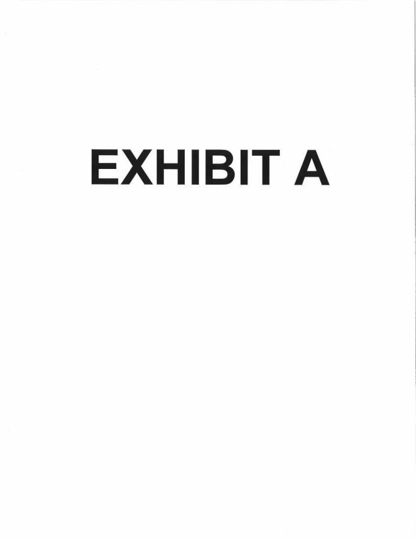
The existing Wilton Facility consists of a 118 foot lattice tower.l T-Mobile plans toreplace three (3) existing antennas, add three antennas on pipe masts attached to tower mounts,and replace existing tower-mounted amplifiers (TMAs) with three (3) TMAs at a centerline of118 feet. T-Mobile will also replace an equipment cabinet on the existing concrete pad, installan equipment cabinet mounted to a proposed H-frame, install fiber cable, install coax cable, andreuse existing coax cable on the _existing ice bridge. (See the plans revised to November 13, 2014attached hereto as Exhibit A). The existing Wilton Facility is structurally capable of supportingT-Mobile's proposed modifications, as indicated in the structural analysis dated November 6,2014, and attached hereto as Exhibit B.
I The Wilton Facility was approved at a height of 118 feet with antenna tops not to exceed 122 feet(Docket No. 308), which is consistent with this filing. T-Mobile's antenna tops will not exceed 120 feet and4 inches.
11]S BROAD STREET 158 DEER HILL AVENUE 3~O POST ROAD WEST 6S~ ORANGE CANTER ROAD
P.O. BOX 1821 DnrrBURY, CI' 06810 WESTroRT, CI' 06880 ORANGE, CI' 06477BRIDGEPORT, ~ ~6~~-1$2~ 'I~c: (203) 7922771 TEL: (203) 222-101 'I~~: (203) 298-4066'[~~: (203) 368-0211 Fax: (203) 791-8149 Fax: (203) 227-1373 Fax: (203) 298068Fax: (203) 3949901

GOH~'NWOLF~P.C.~ATTORNEI'S AT LAW
November 26, 2014Site ID CT11346CPage 2
• The planned modifications to the Wilton Facility fall squarely within those activities
explicitly provided for in R.C.S.A. g 16-50j-72(b)(2).
1 . The proposed modification will not increase the height of the tower. T-Mobile's
existing antennas are at a centerline of 118 feet; the replacement and additional antennas will be
installed at the same 118 foot level, The enclosed tower drawing confirms that the proposed
modification will not increase the height of the tower.
2 . The proposed modifications will not require an extension on the site boundaries
or lease area, as depicted on Sheet 1 of Exhibit A. T-Mobile's equipment will be located entirely
within the existing compound area.
3 . The proposed modification to the Facility will not increase the noise levels at the
existing facility by six decibels or more.
4 . The operation of the replacement and additional antennas and equipment will
not increase the total radio frequency (RF) power density, measured at the base of the tower, to
a level at or above the applicable standard. According to a Radio Frequency Emissions Analysis
Report prepared by EBI dated November 13, 2014, T-Mobile's operations would add 8.03% of
the FCC Standard. Therefore, the calculated "worst case" power density for the planned
combined operation at the site including all of the proposed antennas would be 53.28% of the
FCC Standard as calculated for a mixed frequency site as evidenced by the engineering exhibit
attached hereto as Exhibit C.
For the foregoing reasons, T-Mobile respectfully submits that the proposed replacement
and additional antennas and equipment at the Wilton facility constitutes an exempt
modification under R.C.S.A. ~ 16-50j-72(b)(2). Upon acknowledgement of this exempt
modification, T-Mobile shall commence construction approximately sixty days from the receipt
of the Council's decision.
Sincerely,
~~ ~ VRachel A. Schwartzman, Esq.
cc: Town of Wilton, First Selectman William B. BrennanSBAWestport Broadcasting Co., LLCSheldon Freincle, Northeast Site Solutions
r:-~..~~— i
—
~
1y=.
.al l~ y/~.
i([l TRAIdSFc~RMER t:~ I ~
~E) IvfULTI-METER ~° *~/* lE7 WELL y.,.
~~~~ ~ jYo
, ~~..%i`~F lE) Rt~OF I
(E) GATE—~ j ~ ~--_~~ L
y-1~ Q
(E) WOOD POLE(n'P.~
(E) WOOD FEI~ICE ~,-='~ ~`;
~.
(P) GSM/UMTS/LTE 3106 CABINETTO REPLACE(E) GSM S12000 CABINET on ~~(E) CONC. PAD s"~,'"
~~Y ~,
i>~~
~w
i _E I
r` `~~!,.~ ~5
_ .. ~I
(P) EMERSON—NETXTENDCOMPACT 2416 CABINET X oy,,sMOUNTED TO (P) H—FRAME
------7iiiii
,;,,1,~.~---i
. ,-.'--..~,~:~ f Q~P
N
(E~ BSA ~M~ N~Sa• i sAT~T ~ ~SHELTER
/
c
~~ (El ~PsJ^lAIVTEIJIVA ~;
- r ~.~
~~
(P) (1) 1-5/8' FlBER CABLE(P) (6) 1-5/8' COAX CABLE AND(E) (6) 1-5/8' COAX CABLE TO REMPJN ON(E) ICE BRIDGE
GRAVEL~.01~•1 PO LI N~
(Ej Ei~UIF1.4ENT
~E~ ~\BUILDING
i ._ <.........,. ~ ~
~ ,. ~ -~ VFRI~01~1 ~i~ SHELTER z
~__._ ~—~
_ ~i ~ii
~ / ~r
~~~P) OSM~UMTS QUAD POLE ANTENNA & ~~(P) dd B4 TMATO REPLACE(E) GSM/UMTS QUAD POLE ANTENNA do y~(E) dd B2 TMA
_............_~~.7.L$ECTQR TQTAL OF 3),. - ,.~lir, rd45 1l%
~w,F~_
c•~
~ (P) LTE QUAD POLE ANTENNA ON(P) PIPE MAST(TYP 1/SECTOR, TOTAL OF 3)
SITE PLAN ~N.T.s. LE-1
ALL EQUIPMENT LOCATIONS ARE APPROXIMATE AND ARESUBJECT TO APPROVAL BY LESSEE/LICENSEE'SSTRUCTURAL & RF ENGINEERS. LOCATIONS OF POWER &TELEPHONE FACILITIES ARE SUBJECT TO APPROVAL BYUTILITY COMPANIES.
ICQNFIGURATION
~~
SUBMITTALS
LEAEVA ~ 08.07.14 LEASE EXHIBIT NORTHEAST SITE SOLUTIONS
-- —._._..__ .................................---...—...._....... SITE NUMBER: 54 MAIN STREET, UNIT 3LE FEV 0 08.15.14 TLANTIS GT11346C STURBRIDGE, MA 01566LE REV 1 11.13.14 ~ (508) 434-5237
GROUP SITE NAME:
1340 Centre Street CT346/ OPTASITEWILTONFT FOR
Suite 203 sirenooRess: T-MOBILE NORTHEAST, LLC
Newton, MA 02459 160 DEER RUN RD. a5 GRIFFIN ROAD SOUTH
-- ---- WILTON, CT 06897 BLOOMFIELD, CT 06002
Office: 617-965-0789 OFFICE: (B60) 692-7100
Fax: 617-213-5056 FAX: (860) 692-7159
DRAWN BY: MM CHECKED BY:SM PAGE'I OF3

r-~.,.-
-+i
lE) G=lvl AID
~E) dd [sue
P
BSA '~2~ yN.
(P) GSM/UMTS ANTEN
(P) dd &F TMA
r_v~aT~n~r+
(E) GSM ~I~1T~I~I1~I;~j F) ,j~ 6~ Th4;1
GS6~ AIJTEIdIVA
dd B2 TI~4A
0p~ "J
,.~~J~
P~v~Q~P
G~
(P) GSM/UMiS ANTENNA
(P) dd B4 TMA
(P) LTE ANTENNA
.~,
ANTENNA PLAN 1N.T.s. LE-3
SUBMITTALS
LE REV A 08.07.14
LEREVO 08.15.14 _ TLANTISLE REV 1 11.13.14--_ _.._ .. ------- G R O U P
1340 Centre Street
Suite 203--------- Newton, MA 02459
Office: 67 7-965-0789Fax: 617-213-5056
(P) GSM/UMTS ANTENNA
3m (P) dd B4 TMA$z=N
PROPOSED
LEASE EXHIBITSfTE NUMBER:
CT11346C
SITE NAME:
CT346/ OPTASITEWILTONFTSITE ADDRESS:
160 DEER RUN RD.WILTON, CT 06897
BY: MM ~ CHECKED BY:SM
MODERNIZATION
CONFIGURATION
2CNORTHEAST SITE SOLUTIONS
54 MAIN STREET, UNIT 3STURBRIDGE, MA 01566
(508) 434-5237
FOR
T-MOBILE NORTHEAST, LLC35 GRIFFIN ROAD SOUTHBLOOMFIELD, CT 06002OFFICE: (860) 692-7100FAX: (B60) 69&7159
PAGE20F3

(P) LTE QUAD POLE ANTENNA ON(P) PIPE MAST(iYP 1/SECTOR, TOTAL OF 3)
(P) GSM/UMTS QUAD POLE ANTENNA &(P) dd 64 TMATO REPLACE(E) GSM/UMTS qU,4~ POLE ANTENNA do(E) dd 82 TMA('fYP 1/SECTOR, TOTAL OF 3)
(P) (1) t-5/8' FlBER CABLE(P) (6) t-5/8" COAX CABLE AND(E) (6) 1-5/8' COAX CABLE TO REMAIN ON(E) WAVEGUIDE
(E1 GPS
(P) GSM/UMTS/LTE 3106 CABINET ,411"EI~II~.ATO REPLACE(E) GSM S12000 CABINET on(E) CONC. PAD
(P) EMERSON-NEfXTEND -COMPACT 2416 CABINETMOUNTED TO (P) H-FRAME
CENTER OF PROPOSED T-MOBILE ANTENNAS ~`
__ E`~I~TWG ,4i&T .AIVTEIVIVA _~~~_ELEV.= 110 1 (FjGL) - - -
EXISTING VERIr~N ANTENNA— - ELEV. = 98 t (AGE - - - - ~-
EXISTI~~G IJFXTE-I.. AI~ITFI~~IAELEV = ~ 't (AGLI
EkISIIIVG WHIP ANTENIJA
LJ
SUBMITTALS
LEREVA 08.07.14 LEASE EXHIBIT NORTHEAST SITE SOLUTIONS
......__ .................._._.....-..._........_......_...............I.. SITE NUMBER: 54 MAIN STREET, UNIT 3LE flEV 0 ~8.15•~4 TLANTIS CT11346C STURBRIDGE, MA 01566LE REV 1 11.13.14 ~ (50B) 434-5237- ----- GROUP SITE NAME:
~34o Centre Street CT346/ OPTASITEWILTONFT FOR
Suite 203 sirenooaess: T-MOBILE NORTHEAST, LLC
Newton, MA 02459 160 DEER RUN RD. 35 GRIFFIN ROAD SOUTH
WILTON, CT 06897 BLOOMFIELD, CT 06002
Office: 617-965-0789 OFFICE: (860) 692-7100
Fax: 617-213-5056 FAX: (B6o) 692x159
DRAWN BY: MM CHECKED BY:SM PAGE20F3

C _ N T —K engineeringCentered on Solutions
S t r u c t u r a l Ana 1 y s i s R e p o r t
1 18' Existing World Tower Lattice Tower
Proposed T-MobileAntenna Upgrade
T-Mobile Site Ref: CT9 1346C
SBA Site Management Site Ref: CT98078-L
760 Deer Run RoadWilton, CT
Centek Project No. 74248.000
Date: November 6, 2014
~Ai~yyyi111I~P~ar,rf
lid ~ '~~ ~ ~ ,~
~fe, ~ fRCS e`13:~4~ 1'~'~'~,~ h.i~~~1''F~~.~.~j~ ~~r
4~ z
+~'~'I~d IFf-I ti'. ~4ti.,
Prepared for:SBA Site Management
1480 Route 9 North, Suite 303Woodbridge, NJ 07095
63-2 Narth Branford Road, Branford, CT 06405 203.488.0580 Fax 203.488.8587 www.CentekEng.com
CENTEK Engineering, Inc.Structural Analysis - 718-ft Lattice TowerT-Mobile Antenna Upgrade — CT11346CSBA Site Ref — CT98078-LWilton, CTNovember 6, 2014
Table of Contents
SECTION 1 - REPORT
■ INTRODUCTION.
■ ANTENNA AND APPURTENANCE SUMMARY.
■ PRIMARY ASSUMPTIONS USED IN THE ANALYSIS.
■ ANALYSIS.
■ TOWER LOADING.
■ TOWER CAPACITY.
■ FOUNDATION AND ANCHORS.
■ CONCLUSION.
SECTION 2 — CONDITIONS &SOFTWARE
■ STANDARD ENGINEERING CONDITIONS.
■ GENERAL DESCRIPTION OF STRUCTURAL ANALYSIS PROGRAM.
SECTION 3 — CALCULATIONS
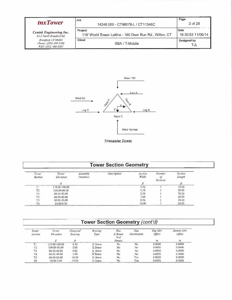
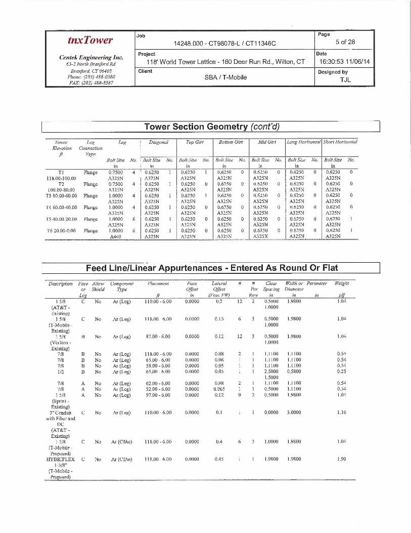
■ tnxTower INPUT/OUTPUT SUMMARY.
■ tnxTower FEED LINE PLAN.
■ tnxTower FEED LINE DISTRIBUTION.
■ tnxTower DETAILED OUTPUT.
■ FOUNDATION ANALYSIS.
SECTION 4 — REFERENCE MATERIALS
■ ANTENNA CUT SHEETS.
TABLE OF CONTENTS TOC-1

CENTEK Engineering, (nc.Structural Analysis - 718-ft Lattice TowerT-Mobile Antenna Upgrade — CT11346CSBA Site Ref — CT98078-LWilton, CTNovember 6, 2014
Introduction
The purpose of this report is to summarize the results of the non-linear, P-4 structural analysisof the antenna upgrade proposed by T-Mobile on the existing self-supporting lattice tower,owned and operated by SBA located in Wilton, Connecticut.
The host tower is a 118-ft, three legged, tapered lattice tower originally designed andmanufactured by World Tower dated October 16, 2006. The tower geometry, structure membersizes and foundation information were taken from the original tower design documents.
Antenna and appurtenance inventory were taken from a previous structural analysis reportprepared by Centek Enginnering job no; 11049.001 dated May 23, 2011, a tower mappingreport prepared by Eastern Communications dated November 3, 2014 and a T-Mobile/SBAamendment application.
The tower is made of six (6) tapered vertical sections consisting of solid round steel legsconforming to ASTM A572-50. Diagonal and horizontal lateral support bracing consists of steelangle shapes conforming to ASTM A36. All connections were bolted connections. The width ofthe tower face is 5.5-ft at the top and 11.5-ft at the base.
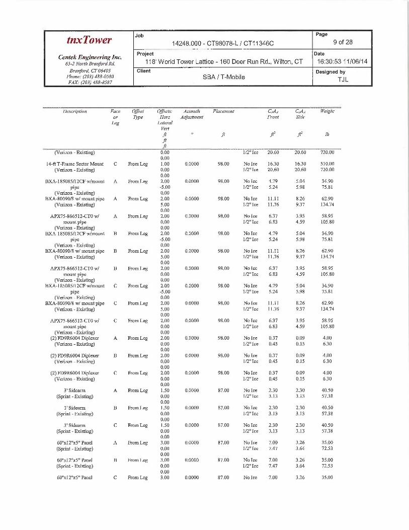
T-Mobile proposes the removal of three (3) existing panel antennas and six (6) TMA's and theinstallation of six (6) panel antennas and three (3) TMA's on proposed replacement mounts.Refer to the Antenna and Appurtenance Summary below for a detailed description of theproposed antenna configuration.
Antenna and Aaaurtenance Summar
The existing tower supports several communication antennas. The existing and proposed loadsconsidered in the analysis consist of the following:
■ UNKNOWN (Existing):Antenna: One (1) 12' x 3" Dia. Omni-directional whip antenna and one (1) 10' x 3"Dia. Omni-directional whip antenna pipe mounted to a leg of the existing tower withrespective RAD center elevations of ±124-ft and ±123-ft above grade level.Coax Cable: Two (2) 7/8" Q coax cables running on a leg/face of the existing toweras specified in Section 3 of this report.
AT&T (Existing):Antennas: Six (6) Powerwave 7770 panel antennas, three (3) Powerwave P65-16-XLH-RR panel antennas, five (5) LGP21401 TMA's, one (1) Andrew E15Z01P13TMA, six (6) Ericsson RRUS-11 remote radio heads and two (2) Raycap DC6-48-60-18-8F surge arrestors mounted on three (3) 14-ft Sector Frames with a RAD centerelevation of ±110-ft above grade level.Coax Cables: Twelve (12) 1-5/8" 6 coax cables, one (1) 3" flex conduit running on aleg/face of the existing tower as specified in Section 3 of this report.
REPORT SECTION 1-1
CENTEKFngi~~eerii~g, Inc.Structural Analysis - 778-ft Lattice TowerT-Mobile Antenna Upgrade — CT11346CSBA Site Ref — CT98078-LWilton, CTNovember 6, 2014
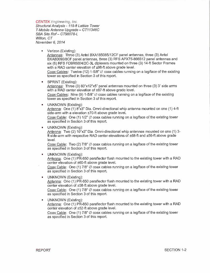
■ Verizon (Existing):Antennas: Three (3) Antel BXA185085/12CF panel antennas, three (3) AntelBXA80090/8CF panel antennas, three (3) RFS APX75-866512 panel antennas andsix (6) RFS FD9R6004/2C-3L diplexers mounted on three (3) 14-ft Sector Frameswith a RAD center elevation of ±98-ft above grade level.Coax Cables: Twelve (12) 1-5/8" Q~ coax cables running on a leg/face of the existingtower as specified in Section 3 of this report.
■ SPRINT (Existing):Antennas: Three (3) 60"x12"x5" panel antennas mounted on three (3) 3' side armswith a RAD center elevation of ±87-ft above grade level.Coax Cables: Nine (9) 1-5/8" ~ coax cables running on a leg/face of the existingtower as specified in Section 3 of this report.
■ UNKNOWN (Existing):Antenna: One (1) 8"x3" Dia. Omni-directional whip antenna mounted on one (1) 4-ftside-arm with a elevation ±70-ft above grade level.Coax Cable: One (1) 1/2" QJ coax cables running on a leg/face of the existing toweras specified in Section 3 of this report.
■ UNKNOWN (Existing):Antenna: Two (2) 10"x3" Dia. Omni-directional whip antennas mounted on one (1) 3-ft side-arm with respective RAD center elevations of ±68-ft and ±56-ft above gradelevel.Coax Cable: Two (2) 7/8" Q1 coax cables running on a leg/face of the existing toweras specified in Section 3 of this report.
■ UNKNOWN (Existing):Antenna: One (1) PR-850 paraflector flush mounted to the existing tower with a RADcenter elevation of ±60-ft above grade level.Coax Cable: One (1) 7/8" QS coax cables running on a leg/face of the existing toweras specified in Section 3 of this report.
■ UNKNOWN (Existing):Antenna: One (1) PR-850 paraflector flush mounted to the existing tower with a RADcenter elevation of ±58-ft above grade level.Coax Cable: One (1) 7/8" P~ coax cables running on a leg/face of the existing toweras specified in Section 3 of this report.
■ UNKNOWN (Existing):Antenna: One (1) PR-850 paraflector flush mounted to the existing tower with a RADcenter elevation of ±52-ft above grade level.Coax Cable: One (1) 7/8" ~ coax cables running on a leg/face of the existing toweras specified in Section 3 of this report.
REPORT SECTION 1-2
CENTEK Engineering, It~c.Structural Analysis - 718-ft Lattice TowerT-Mobile Antenna Upgrade — CT1 ~346CSBA Site Ref — CT98078-LWilton, CTNovember 6, 2074
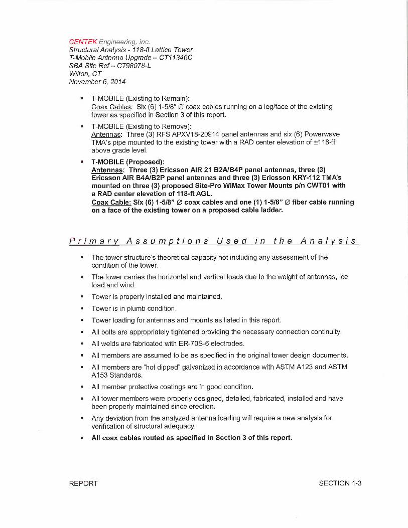
■ T-MOBILE (Existing to Remain):Coax Cables: Six (6) 1-5/8" Q1 coax cables running on a leg/face of the existingtower as specified in Section 3 of this report.
■ T-MOBILE (Existing to Remove):Antennas: Three (3) RFS APXV18-20914 panel antennas and six (6) PowerwaveTMA's pipe mounted to the existing tower with a RAD center elevation of ±118-ftabove grade level.
■ T-MOBILE (Proposed):Antennas: Three (3) Ericsson AIR 21 B2A/B4P panel antennas, three (3)Ericsson AIR B4A/B2P panel antennas and three (3) Ericsson KRY-112 TMA'smounted on three (3) proposed Site-Pro WiMax Tower Mounts p/n CWT01 witha RAD center elevation of 118-ft AGL.Coax Cable: Six (6) 1-5/8" Q~ coax cables and one (1)1-5/8" Q1 fiber cable runningon a face of the existing tower on a proposed cable ladder.
Primary Assumptions Used in the Analysis
■ The tower structure's theoretical capacity not including any assessment of thecondition of the tower.
■ The tower carries the horizontal and vertical loads due to the weight of antennas, iceload and wind.
■ Tower is properly installed and maintained.
■ Tower is in plumb condition.
■ Tower loading for antennas and mounts as listed in this report.
■ All bolts are appropriately tightened providing the necessary connection continuity.
■ All welds are fabricated with ER-70S-6 electrodes.
■ All members are assumed to be as specified in the original tower design documents.
■ All members are "hot dipped" galvanized in accordance with ASTM A123 and ASTMA153 Standards.
■ All member protective coatings are in good condition.
■ All tower members were properly designed, detailed, fabricated, installed and havebeen properly maintained since erection.
■ Any deviation from the analyzed antenna loading will require a new analysis forverification of structural adequacy.
■ All coax cables routed as specified in Section 3 of this report.
REPORT SECTION 1-3

CENTEK Engii~eeri~~g, li~c.Structural Analysis - 118-ft Lattice TowerT-Mobile Antenna Upgrade — CT11346CSBA Site Ref — CT98078-LWilton, CTNovember 6, 2014
Analysis
The existing tower was analyzed using a comprehensive computer program entitled Tnxtower.The program analyzes the tower, considering the worst case loading condition. The tower isconsidered as loaded by concentric forces along the tower shaft, and the model assumes thatthe shaft members are subjected to bending, axial, and shear forces.
The existing tower was analyzed for the controlling basic wind speed (fastest mile) with no iceand a 75% reduction of wind force with %inch accumulative ice to determine stresses inmembers as per guidelines of TIA/EIA-222-F-96 entitled "Structural Standards for Steel AntennaTowers and Antenna Supporting Structures", the American Institute of Steel Construction(AISC) and the Manual of Steel Construction; Allowable Stress Design (ASD).
The controlling wind speed is determined by evaluating the local available wind speed data asprovided in Appendix K of the CSBC' and the wind speed data available in the TIA/EIA-222-F-96 Standard. The higher of the two wind speeds is utilized in preparation on the tower analysis.
Tower Loading
Tower loading was determined by the basic wind speed as applied to projected surface areaswith modification factors per TIA/EIA-222-F, gravity loads of the tower structure and itscomponents, and the application of/2" radial ice on the tower structure and its components.
Basic WindSpeed:
Fairfield; v = 85 mph (fastest mile) Section 16 of TIA/EIA-222-F-96]
Wilton; v = 100 mph (3 second gust)equivalent to v = 80 mph (fastest (Appendix K of the 2005 CTmile) Building Code Supplement]
TIA/EIA wind speed controls.
Load Cases: Load Case 1; 85 mph wind speed w/ Section 2.3.16 of T/A/E/A-222-F-no ice plus gravity load —used in 96]calculation of tower stresses androtation.
Load Case 2; 74 mph wind speed w/%2" radial ice plus gravity load —usedin calculation of tower stresses. The74 mph wind speed velocityrepresents 75% of the wind pressuregenerated by the 85 mph windspeed.
Load Case 3; Seismic —not checked
(Section 2.3.16 of T/A/EIA-222-F-96]
(Section 1614.5 of State Bldg.Code 2005] does not control inthe design of this structure type
1 The 2005 Connecricut State Building Code as amended b5~ the 2009 CT State Supplement. (CSBC)
REPORT SECTION 1-4
CENTEK Engi~~eerir~g, It~c.Structural Analysis - 118-ft Lattice TowerT-Mobile Antenna Upgrade — CT11346CSBA Site Ref — CT98078-LWilton, CTNovember 6, 2014
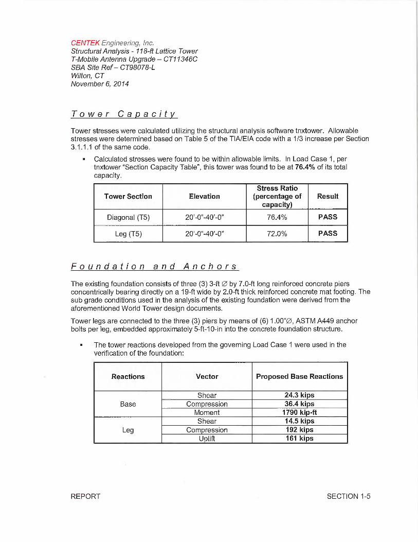
Tower Capacity
Tower stresses were calculated utilizing the structural analysis software tnxtower. Allowablestresses were determined based on Table 5 of the TIA/EIA code with a 1/3 increase per Section3.1.1.1 of the same code.
■ Calculated stresses were found to be within allowable limits. In Load Case 1, pertnxtower "Section Capacity Table", this tower was found to be at 76.4% of its totalcapacity.
Stress RatioTower Section Elevation (percentage of Result
capacity)
Diagonal (T5) 20'-0"-40'-0" 76.4% PASS
Leg (T5) 20'-0"-40'-0" 72.0% PASS
Foundation and Anchors
The existing foundation consists of three (3) 3-ft QS by 7.0-ft long reinforced concrete piersconcentrically bearing directly on a 19-ft wide by 2.0-ft thick reinforced concrete mat footing. Thesub grade conditions used in the analysis of the existing foundation were derived from theaforementioned World Tower design documents.
Tower legs are connected to the three (3) piers by means of (6) 1.00"~, ASTM A449 anchorbolts per leg, embedded approximately 5-ft-10-in into the concrete foundation structure.
The tower reactions developed from the governing Load Case 1 were used in theverification of the foundation:
Reactions Vector Proposed Base Reactions
Shear 24.3 kipsBase Compression 36.4 kips
Moment 1790 kip-ftShear 14.5 kips
Leg Compression 192 kipsUplift 161 kips
REPORT SECTION 1-5

CENTEK Engir~ee~ina, lnc.Structural Analysis - 118-ft Lattice TowerT-Mobile Antenna Upgrade — CT91346CSBA Site Ref — CT98078-LWilton, CTNovember 6, 2014
■ The anchor bolts and base plate were found to be within allowable limits.
Tower Stress Ratio
Component Design Limit (percentage of Result
capacity)
Anchor Bolts Tension 62.4°/a PASS
■ The foundation was found to be within allowable limits.
IBC 2003/2005 pro osed
Foundation Design CT State Building
Loadin ResultLimit Code Section
FS ~,~g3108.4.2 (FS)~'~ ~ ~
Reinforced OTM~2~ 2.0 2.19 PASS
Concrete Mat
Conclusion
This analysis shows that the subject tower is adequate to support the proposed modifiedantenna configuration.
The analysis is based, in part, on the information provided to this office by T-Mobile and SBA. Ifthe existing conditions are difFerent than the information in this report, Centek Engineering, Inc.must be contacted for resolution of any potential issues.
Please feel free to call with any questions or comments.
Respectfully Submitted by:~~
- ~",1. j~ - ~,.~.
- it
i
Timothy J. Lynn, PEStructural Engineer
~~~~t~~~iitr r~~~
~~~` C.0 t; C 111 rV,~ ~~ri;~
t ~~ ~~~
ti No.2933fi~~~4
fi<<~i
~£idSF- [~ -:,.~
~~'>1~4il1St4~~?\
REPORT SECTION 1-6

CENTEK Engi~~eeriny, Inc.Structural Analysis - 178-ft Lattice TowerT-Mobile Antenna Upgrade — CT11346CSBA Site Ref — CT98078-LWilton, CTNovember 6, 2074
Standard Conditions for Furnishing ofProfessional Engineering Services onExisting Structures
All engineering services are performed on the basis that the information used is current andcorrect. This information may consist of, but is not necessarily limited to:
Information supplied by the client regarding the structure itself, its foundations, the soilconditions, the antenna and feed line loading on the structure and its components, orother relevant information.
Information from the field and/or drawings in the possession of CENTEK engineering,Inc. or generated by field inspections or measurements of the structure.
It is the responsibility of the client to ensure that the information provide to CENTEKengineering, Inc. and used in the performance of our engineering services is correct andcomplete. In the absence of information to the contrary, we assume that all structureswere constructed in accordance with the drawings and specifications and are in an un-corroded condition and have not deteriorated. It is therefore assumed that its capacityhas not significantly changed from the "as new" condition.
All services will be performed to the codes specified by the client, and we do not imply tomeet any other codes or requirements unless explicitly agreed in writing. If wind and iceloads or other relevant parameters are to be different from the minimum valuesrecommended by the codes, the client shall specify the exact requirement. In theabsence of information to the contrary, all work will be performed in accordance with thelatest revision of ANSI/ASCE10 &ANSI/EIA-222
All services performed, results obtained, and recommendations made are in accordancewith generally accepted engineering principles and practices. CENTEK engineering, Inc.is not responsible for the conclusions, opinions and recommendations made by othersbased on the information we supply.
REPORT SECTION 2-1

CENTEK Engineerii~c~., Inc.Structural Analysis - 718-ft Lattice TowerT-Mobile Antenna Upgrade — CT11346CSBA Site Ref — CT98078-LWilton, CTNovember 6, 2014
General Description of StructuralAnalysis Program
tnxTower, is an integrated structural analysis and design software package for Designedspecifically for the telecommunications industry, tnxTower, formerly ERITower, automates muchof the tower analysis and design required by the TIA/EIA 222 Standard.
tnxTower Features:
tnxTower can analyze and design 3-and 4-sided guyed towers, 3- and 4-sided self-supporting towers and either round or tapered ground mounted poles with or withoutguys.
The program analyzes towers using the TIA-222-G (2005) standard or any of theprevious TIA/EIA standards back to RS-222 (1959). Steel design is checked using theAISC ASD 9th Edition or the AISC LRFD specifications.
Linear and non-linear (P-delta) analyses can be used in determining displacements andforces in the structure. Wind pressures and forces are automatically calculated.
Extensive graphics plots include material take-off, shear-moment, leg compression,displacement, twist, feed line, guy anchor and stress plots.
tnxTower contains unique features such as True Cable behavior, hog rod take-up,foundation stiffness and much more.
REPORT SECTION 2-2

DESIGNED APPURTENANCE LOADING
C ~C 4
4
c ~ ~ ~
C 4
'~ ~~ ~
e `
~ p — ~
_ _ 2 g 3_ _ 3 ~
~
I' ~~~~
TOWER DESIGN NOTES
~~u
~.a~~~
'~
MU~X CORNER REACTIONS AT6ASEGOWN: 19187516UPLIFT.• -16107316SHEAR: 1446916
A:CIi7L36375 ib
SHEAR MOMEM2432416 179019116af
70RQUE723116-ft74 mph tMND- 0.5000 in ICE
AXIAL2201816
SHEAR MOMEAT2291616 1721807 @-lf
TORQUE 803616-ftREACTIONS-85 mph WIND
TYPE ELEVATION TYPE ELEVATION12z3'ge OtM 124 14-HT-FrsmeSMor Movl (VMzon-Etlstlig) 99
1V x3'Dia prci 123 14-HT-Trams 5edor Mout (Valm~-EtlSWg) 9B
6Y1'PIFe Maul ne aYn-iasoesnxFwmn~n paaN~o~- sa6Y1'Plpe Moul 118 ~~~)
6Yp'Plpe Moue. 118 BXMBWSRVBMmout plpeN~an-Fs'Al~g) 9B
(2)AIR21 R~AtoGOe-PmposeE) ti8 ~%~~512CTOWmoutpipe(Ve~lian-
(2)AIfl21 (~-Mod@-Purposed) 118 ~su~~ ~
(2)AIfl21 (~-MobR-Pmpns~) 118 ewe-iewesn2ccwtmvw qce C/~on- saENsO J)
IQ3Y 112TA1A(~JAahie-Pmposd) 118 B%h8WBd0 wimout on-Eud 9B
KRY 112TMA(I-IAadk-Pmposci) 1B gpaj5A66512-CTOWmaut pipe (Vertrnn- 9B
piY 112TMP(t'Matlh-PmposeE) 118 ~yry'~)
SM Pm Campatl TovrerMout~T-Xbtlle- 11B B%A-1BSOB5I14CFxfiwt~I plpa Neon- 9BSi°WseEl Etlsd9)IIe Pm Cnmpatl To~Movl(~-Modk- 118
BXh801196'B xVmov{plpeN~on-0191~g) eBPmposetl)
SIIe Pm Competl To~mr Movl (T-A1oM@- 11B ~~686G512CTOWmoul plpe (Ve~izon- W
Pmroseal ~,asme)(2)F09RWD901pk r(Vulzon-EtlSLg) eB
iVG Slle PmT-Mn NTI-Etl91 110 RIFwHsooa uia~~r Ne~non-eb~oy~ setU65Xe Pm T-Mn AlI-Egstl~g) 110 ~)~~pgp~~Ny~on-Etlsling) 89tU6511e Pm T-Mn AR-Ebsllrg 110
3'SIMa~m (SgIH-Etlztleg) 8!2 T//0.00 ATI-Fdsfi 110
ySltleemi l5gi~1-Etlstl~g) Bi(2)]]10.00 (ATI-Etlstl ]) SSldrann lSMrt-EYztleg) ~2 ]110.00 AlI-ENsO 110 SP~~-Pere119pN1-EtlsThg)EtY01P13 A1I-E+051i~g} 110 gpx12SS Pere)~SpM-Etl91rg) H/1PG21dOt TAM (ATI-Etlztl~ 110
5p~K1YtE Perel(Spiit-Ex's1M1g) 0]21PG21401 TMA ATI-Edsl 110 @xT~IaQM ]4-fib21PG211~i TMA AIZ-EvsO 114 ~px3'D~eOmi ]3-63P6S16%LH~RR ATI-Ebstlfg) »0
gSiham 61P&416X1H.R0. (ATI-ENsllfg) 110
d'SlGaertn fi5P6S16%LH.RR ATI-Etl9i 110 3'Sitleam 6227 ~~5-11 (qTi-Etlglig 110
iPx3'Ola Omi et-51(21 ~U5.11 (ATL-Eusiingl 110 PRA ~
2 RRV5.11 (ATj-Epstl 1 HO
(21 ~6~9.fi0.188G5uge Meslor(ATI- 114 Pft850 50
EtlsWg) PftRS~ 52
14tIT-Frsme Sector Mou'I~Veiizon-EtlsWg)
rna.-rEwa,~ sraENcrHGRADE F Fu GRADE Fu
AS)2-50 SOIN &51¢I R36 381x1 SB I¢I
1. Taver designed fora B5 mph basic wind in accordance with the TUVEW-222-F Standard.2. Tower is also designetl for e 74 mph basic wind vrith D.50 in Ice.3. Deflections are based upon a 50 mph wind.4. Weld tope[her[ower sections ha~.z 9ange connections.5. Connections use galvanized A3256oIts, nuts and locking tletices. Installation cerTWEIA-222 antl AISC Spec~ications.6. Tower members are°hot dipped"galvanizetl in accordance with ASTMA123 antl A5TM A1535tantlards.7. Welds are fabricated with ER-7058 electrodes.8. TOW ER RATING: 76.4%
Cenfek Engineering Inc "' 14248.000 - CT98078-L / CT11346C
632NorthBranfordRd. P'°x"'~~a~wondr rLattice•160PeerRanRd,lM14lton,C
Branford, CT 06405 ~~ SBA/T-Mobile Qa""q'TJL mod'
Phone: (203)48&0580 m°0' TIA/EW-222-F ~`' 11/OW14 ~` NTS
FAX: 203 48&8587 Pte ~NO'Et
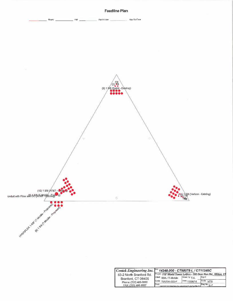
Feedline Plan
Round Flat App In Face _ _ App Ou[ Face
;onduit with Fiber a~
~~~ Q~v~o ~e~' ~o'p~
h
Q~~~. `1
-1~
(Verizon - E~sting)
Centek Engineering InG °h' 14248.000 - CT98078-L / CT11346C
63-2 North Branford Rd. P'OfeC`~~~s'WorldTowerLatfice-160 Deer RunRd., ~Iton, C
Branford, CT 06405 client SBA/T-Mobile °ra`xneyTJL '4PP~d'
Phone: (203) 488-0580 Code: TIA/EIA-222-F Date:. 1/06/14 Scale: NTS
FAX: 203 488-8587 Path: Dwg No. E_~

Feedline Distribution Chart0' -118'
Round Flat App In Face ~ App Ou[ Face Truss Leg
.-.
CO
R
dW
Centek Engineering Ins °b' 14248,000 - CT98078-L / CT11346C
63 2 North Branford Rd. P`Oje":~~a`Wor/dTowerLaffice-160 Deer RunRd.,Wi/ton, C
Branford, CT 06405 Client SBA/T-Mobile ~'~`""by: TJL App'd:
Phone: (203) 488-0580 Code: TIA/EIA-222-F Date:11/06/14 Scale: NTS
FAX: 203 488-8587 Pafh: Dwg Na. E-7
Farce A Fare 6 Face C

Job Page
tnxTowe~ 14248.000 - CT98078-L / CT11346C 1 of 28
CentekEngineeringlnc. Project gate
63-2 North Branford Rd. ~ ~$' World Tower Lattice - 160 Deer Run Rd., Wilton, CT 16:30:53 11/06/14
Branford, CT 06405 Client Designed byPhone: (203) 488-0580 SBA / T-Mobile TJLFAX. (203) 488-8587
Tower Input Data
'The main tower is a 3x free standing tower with an overall height of 118.00 ft above the ground line.The base of the tower is set at an elevation of 0.00 ft above the ground line.The face width of the tower is 5.50 ft at the top and 11.50 ft at the base.This tower is designed using the TIA/EIA-222-F standard..The following design criteria apply:
Basic wind speed of 85 mph.Nominal ice thickness of 0.5000 in.Ice density of 56 pcf.A wind speed of 74 mph is used in combination with ice.Temperature drop of 50 °F.Deflections calculated using a wind speed of 50 mph.Weld together tower sections have flange connections..Connections use galvanized A325 bolts, nuts and locking devices. Installation per TIA/EIA-222 and AISCSpecifications..Tower members are "hot dipped" galvanized in accordance with ASTM A123 and ASTM A153 Standards..Welds are fabricated with ER-70S-6 electrodes..Anon-linear (P-delta) analysis was used.Pressures are calculated at each section.Stress ratio used in tower member design is 1333.Local bending stresses due to climbing loads, feedline supports, and appurtenance mounts are not considered.
Options
Consider Moments -LegsConsider Moments -HorizontalsConsider Moments -DiagonalsUse Moment MagnificationUse Code Stress RatiosUse Code Safety Factors -GuysEscalate IceAlways Use Max KzUse Special Wind ProfileInclude Bolts In Member CapacityLeg Bolts Are At Top Of SectionSecondary Horizontal Braces LegUse Diamond Inner Bracing (4 Sided)Add IBC .6D+W Combination
Distribute Leg Loads As UniformAssume Legs PinnedAssume Rigid Index PlateUse Clear Spans For Wind AreaUse Cleaz Spans For KI./rRetension Guys To Inirial TensionBypass Mast Stability ChecksUse Azimuth Dish CoefficientsProject Wind Area ofAppurt.Autocalc Torque Arm AreasSR Members Have Cut EndsSort Capacity Reports By ComponentTriangulate Diamond Inner Bracing
Treat Feedline Bundles As CylinderUse ASCE 10 X-Brace Ly RulesCalculate Redundant Bracing ForcesIgnore Redundant Members in FEASR Leg Bolts Resist CompressionAll Leg Panels Have Same AllowableOffset Girt At FoundationConsider Feedline TorqueInclude Angle Block Shear Check
PolesInclude Shear-Torsion InteractionAlways Use Sub-Critical FlowUse Top Mounted Sockets
Job Page
tn~Tower 14248.000 - CT98078-L / CT11346C 2 of 28
Ce~~tek E~xgineeri~zg Inc. Project Date
63-z No~~rt~a,~a~,fo,~ana. 118' World Tower Lattice - 160 Deer Run Rd., Wilton, CT 16:30:53 11/06/14
Branford, CT 06405 Client Designed byPhone: (z03) 488-0580 SBA / T-MOblle TJLFAX.• (203) 488-8587
Wind 180
,~ Lea A
Wind 90~ P no~
~a° ~
Leg C Z
Face C
Wind Normal
TI'18lig(Ild/" TOW@I"
Tower Section Geometry
~j Toi~~er~ Toia~er~ ~~~% Assen7bly Description Section Number Sectio~a
Sectio~a Elei~aiio» Database Widt1~ of LengthSectio~as
Tl 118.00-100.00 5.50 1 18.00
T2 100.00-80.00 5.50 1 20.00
T3 80.00-60.00 5.50 1 20.00T4 60.00-40.00 7.00 1 20.00TS 40.00-20.00 8.50 1 20.00
T6 20.00-0.00 10.00 1 20.00
Tower Section Geometry (cont'd)
Toiaer Towet• Diago~aal Bracing Has Has Top Girt Bottom Giri
Seclio~z Elevatio~a Spacing Type KBr•ace Horizontals Offset OffsetEnd
ft ft Panels ira i»
T1 118.00-100.00 4.50 XBrace No No 0.0000 0.0000
T2 100.00-80.00 5.00 X Brace No No 0.0000 0.0000
T3 80.00-60.00 5.00 X Brace No No 0.0000 0.0000
T4 60.00-40.00 5.00 X Brace No No 0.0000 0.0000
TS 40.00-20.00 10.00 X Brace No Yes 0.0000 0.0000
T6 20.00-0.00 10.00 X Brace No Yes 0.0000 0.0000

Job Page
tnxTower 14248.000 - CT98078-L / CT11346C 3 of 28
Centek Engi~zeering Inc. Project Date
63-2 North Branford Rd. ~ ~$' World Tower Lattice - 160 Deer Run Rd., Wilton, CT 16:30:53 11/06/14
Branford, CT 06405 Client Designed byPhone (203) 488-0580 SBA / T-Mobile TJLFAX. (203) 488-8587
Tower Section Geometry (cont'd)
Toiae~ Leg Leg Leg Diagonal Diago~aal ~ Diagonal
Elevatio~i Type Size Grade Type Size Grade
TI118.00-100.00 Solid Round 13/4 A572-50 Equal Angle L2xZx1/8 A36(50 ksi) (36 ksi)
T2 100.00-80.00 Solid Round 2 1/2 A572-50 Equal Angle L2x2x3/16 A36(50 ksi) (36 ksi)
T3 80.00-60.00 Solid Round 2 3/4 A572-50 Equal Angle L2~.x3/16 A36(50 ksi) (36 ksi)
T4 60.0040.00 Solid Round 3 A572-50 Equal Angle L2xZx3/16 A36(50 ksi) (36 ksi)
TS 40.00-20.00 Solid Round 3 1/4 A572-50 Equal Angle L3x3x1/4 A36(50 ksi) (36 ksi)
T620.00-0.00 Solid Round 31/2 A572-50 Equa]Angle L3x3x1/4 A36(50 ksi) (36 ksi)
Tower Section Geometry (cont'd)
To~~er Top Girt ~~~ Top Girt S~Top Girt Bottom Girl ~~~ Boftol~t Girt ~ Bottom Girt
Elevatio~7 Type Size Grade Type Size Grade
T1 118.00-100.00 Equal Angle L2x2x1/8 A36 Equal Angle A36
(36 ksi) (36 ksi)
T3 80.00-60.00 Equal Angle L2ac2x1/8 A36 Equal Angle A36(36 ksi) (36 ksi)
Tower Section Geometry (cont'd)
Tower Seco~tda~y Seco~tdaryHorizantal Seco~adary b~nerBraciiag In~terBracingSize btnerBracing
Elevatioi7 Horizwatal Type Size Horizmttal Type GradeGrade
TS 40.00-20.00 Equal Angle L21c2x1/8 A36 Equal Angle A36(36 ksi) (36 ksi)
T6 20.00-0.00 Equal Angle L2ac2x1/8 A36 Equal Angle A36(36 ksi) (36 ksi)
Tower Section Geometry (cont'd)
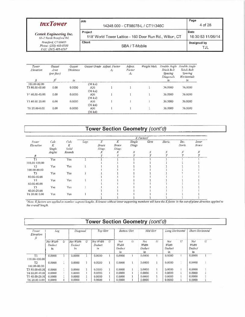
Toia~er Gusset Garsset Gusset Grade Adjust. Factor Adjatst. I~i'eigbt Mult. Dozrble Angle Dortble A»gle
Elevatio~a Area 77~ich~vess A~ Facior Stitch Bolt Stitc7~ Bolt
(per face) A, Sacing SpacingDiagm~als Horizontals
f( ~ 777 DT I7T
T1 0.00 0.0000 A36 1 1 1 36.0000 36.0000
118.00-100.00 (36 ksi)T2 0.00 0.0000 A36 1 1 1 36.0000 36.0000
Job Page
t~xTower 14248.000 - CT98078-L / CT11346C 4 of 28
CentekEngineerfnglnc. Project Date
63-zNo~~ri,a,~A~,fo,~axa. 118' World Tower Lattice - 160 Deer Run Rd., Wilton, CT 16:30:53 11/06/14
Bra~7ford, CT 06405 Client Designed byPho~Te: (203) 488-0580 SBA / T-Mobile TJLFAX. (203) 488-8587
Tower Gusset Gzrsset Gusset Grade Adjz~st. Factor ~ Adjust. Weight Mult. Double A~agle Double A~agleElenatior~ Area TlaicTn7ess Aj Factor Stitch Bolt Stitch Bolt
(per face) A, Spacing Spaci~agDiago»als Horizontals
ft ft- in _vu~ ~ i~a in
100.00-80.00 (36 ksi)T3 80.00-60.00 0.00 0.0000 A36 1 1 1 36.0000 36.0000
(36 ksi)T4 60.00-40.00 0.00 0.0000 A36 1 1 1 36.0000 36.0000
(36 ksi)TS 40.00-20.00 0.00 0.0000 A36 1 1 1 36.0000 36.0000
(36 ksi)T6 20.00-0.00 0.00 0.0000 A36 1 1 1 36.0000 36.0000
(36 ksi)
Tower Section Geometry (cont'd)
K Factors
Toia~er Calc Calc Legs X K Singe Girts Horiz. Sec. Inner
Elevatio~t K K Brace Brace Diags Horiz. BraceSingle Solid Diags DiagsA~agles Rounds X X X X X X X
ft Y Y Y Y Y P Y
T1 Yes Yes 1 1 1 1 1 1 1 1118.00-100.00 1 1 1 1 1 1 1
T2 Yes Yes 1 1 1 1 1 1 1 1100.00-80.00 1 1 1 1 1 1 1
T3 Yes Yes ] 1 1 1 1 1 1 I
80.00-60.00 1 1 1 1 I 1 1T4 Yes Yes 1 1 1 1 1 1 1 1
60.00-40.00 1 1 1 1 1 1 1
TS Yes Yes 1 1 1 1 1 1 1 140.00-20.00 1 1 1 1 1 1 1
T6 20.00-0.00 Yes Yes 1 1 1 1 1 1 1 11 1 1 1 1 1 1
`Note: Kfaclors are applied to member segment lengths. K-braces without inner supportirTg members will have the Kfactor~ in tl7e out-of-plane di~~ection applied tothe overall length.
Tower Section Geometry (cont'd)
~~Toia~er Leg ~ Diagonal ~ ~SaTop Girt Bottom Girt Mid Girt Long Horizontal SlaortHorizmttalElenatiora
Net Tl'idth U Net YPidth U Net ii~idt7a U Net U Net U Net U Net UDeduct Dedz~ct Deduct iVidt7t YVidth N~idtb N'idth
in in in Dedzrct Deduct Deduc! Deductin in in in
T 1 0.0000 1 0.0000 1 0.0000 1 0.0000 1 0.0000 1 0.0000 1 0.0000 1118.00-100.00
T2 0.0000 1 0.0000 1 0.0000 1 0.0000 1 0.0000 1 0.0000 1 0.0000 I100.00-80.00T3 80.00-60.00 0.0000 1 0.0000 1 0.0000 1 0.0000 1 0.0000 1 0.0000 1 0.0000 1
T4 60.00-40.00 0.0000 1 0.0000 1 0.0000 1 0.0000 1 0.0000 1 0.0000 1 0.0000 1TS 40.00-20.00 0.0000 1 0.0000 1 0.0000 1 0.0000 1 0.0000 1 0.0000 1 0.0000 ]T6 20.00-0.00 0.0000 1 0.0000 1 O.00DO 1 0.0000 1 0.0000 1 0.0000 1 0.0000 1
Job Page
tr~xTower 14248.000 - CT98078-L / CT11346C 5 of 28
Centek Engineering Inc. Project Date
63-zNo~~r~,B~~a„fo~~ana. 118' Worid Tower Lattice - 160 Deer Run Rd., Wilton, CT 16:30:53 11/06/14
Branford, CT 06405 Client Designed byPhmte: (203) 488-0580 SBA / T-Mobile TJLFAX. (203) 488-8587
Tower Section Geometry (cont'd)
Tower Leg Leg Diagonal TopGi~~l Bottom Girt Mid Girt LongHmizmztal Short Horizontal
Elevaliora Cm~rtectionft Type
Bolt Size No. Bolt Size No. Boli Size No. Bolt Size No. Bait Size No. Bolt Size No. Bolt Size No.
in in in in in in in
T] Flange 0.7500 4 0.6250 1 0.6250 1 0.6250 0 0.6250 0 0.6250 0 0.6250 0
118.00-100.00 A325N A325N A325N A325N A325N A325N A325NT2 Flange 0.7500 4 0.6250 I 0.6250 0 0.6250 0 0.6250 0 0.6250 0 0.6250 0
100.00-80.00 A325N A325N A325N A325N A325N A325N A325N
T3 80.00-60.00 Flange 1.0000 4 0.6250 I 0.6250 1 0.6250 0 0.6250 0 0.6250 0 0.6250 0
A325N A325N A325N A325N A325N A325N A325N
T4 60.00-40.00 Flange 1.0000 4 0.6250 1 0.6250 0 0.6250 0 0.6250 0 0.6250 0 0.6250 0A325N A325N A325N A325N A325N A325N A325N
TS 40.00-20.00 Flange 1.0000 6 0.6250 I 0.6250 0 0.6250 0 0.6250 0 0.6250 0 0.6250 1
A325N A325N A325N A325N A325N A325N A325N
T6 20.00-0.00 Flange 1.0000 6 0.6250 1 0.6250 0 0.6250 0 0.6250 0 0.6250 0 0.6250 1
A449 A325N A325N A325N A325X A325N A325N
Feed Line/Linear Appurtenances -Entered As Round Or Flat
Description Face Alloiv Con~po»ent Placen~eiat Face Lateral # # Clear Width or Perimeter T~~eightor Shield Type Offset Offset Per Spacing Diameter
Leg ft in (Prat FT~~ Ro~v iii itt in plf
1 5/8 C No Ar (Leg) 110.00 - 6.00 0.0000 0.2 12 2 0.5000 1.9800 1.04
(AT&T - 1.0000Existing)
1 5/8 C No Ar (Leg) 118.00 - 6.00 0.0000 0.15 6 3 0.5000 1.9800 1.04
(T-Mobile - 1.0000Existing)
1 5/8 B No Ar (Leg) 87.00 - 6.00 0.0000 0.12 12 3 0.5000 1.9800 1.04
(Verizon - 1.0000E~sting)
7/8 B No Ar (Leg) 118.00 - 6.00 0.0000 0.08 2 1 1.1100 1.1100 0.54
7/8 B No Ar (Leg) 65.00 - 6.00 0.0000 0.06 1 1 1.1100 1.1100 0.54
7/8 B No Ar (Leg) 58.00 - 6.00 0.0000 0.05 I 1 1.1100 1.1100 0.54
1/2 B No Ar (Leg) 65.00 - 6.00 0.0000 0.05 1 1 2.5000 0.5800 0.251.5000
7/8 A No Ar (Leg) 62.00 - 6.00 0.0000 0.08 2 1 1.1100 1.1100 0.54
7/8 A No Ar (Leg) 52.00 - 6.00 0.0000 0.065 1 1 0.5000 L1100 0.54
1 5/8 A No Ar (Leg) 97.00 - 6.00 0.0000 0.12 9 2 0.5000 1.9800 1.04(Sprint -E~sting)3"Conduit C No Ar (Leg) 110.00 - 6.00 0.0000 0.1 1 1 0.0000 3.0000 1.16
with Fiber andDC
(AT&T -Existing)1 5/8 C No Ar (CfAe) 118.00 - 6.00 0.0000 0.4 6 3 1.0000 1.9800 1.04
(T-Mobile -Proposed)
HYBRIFLEX C No Ar (CfAe) 118.00 - 6.00 0.0000 0.45 1 1 1.9800 1.9800 1.90
1-5/8"(T-Mobile -Proposed) T

Job Page
tnxTowe~ 14248.000 - CT98078-L / CT11346C 6 of 28
Centek Engineering Inc. Project Date
63-2Nortla Branford Rd. ~ ~8' World Tower Lattice - 160 Deer Run Rd., Wilton, CT 16:30:53 11/06/14
B~•anford, CT 06405 Client Designed byPhone.' (203) 488-0580 SBA / T-Mobile TJLF.9X.~ (203) 488-8587
Feed Line/Linear Appurtenances Section Areasnr.~~ -- - ....~.~._ ~.~. _ ____._____a~,~__.___ _~~
Toia~er Tourer Face AR AF C,iA,~ C,IA~ YPeigl~t
Section Elevation ba Face Out Facefr 1i' fr ft' fr' Tb
T1 118.00-100.00 A 14.710 0.000 0.000 0.000 0.00B 1.665 0.000 0.000 0.000 19.44
C 28.255 0.000 0.000 0.000 395.24T2 100.00-80.00 A 27.110 0.000 0.000 0.000 159.12
B 10.925 0.000 0.000 0.000 108.96
C 40.015 0.000 0.000 0.000 560.40
T3 80.00-60.00 A 28.285 0.000 0.000 0.000 18936B 19.239 0.000 0.000 0.000 275.15
C 47.154 0.000 0.000 0.000 560.40
T4 60.00-40.00 A 31.060 0.000 0.000 0.000 215.28B 25.792 0.000 0.000 0.000 296.72
C 50.932 0.000 0.000 0.000 560.40
TS 40.00-20.00 A 31.800 0.000 0.000 0.000 219.60B 26.717 0.000 0.000 0.000 297.80
C 51.117 0.000 0.000 0.000 560.40
T6 20.00-0.00 A 22.260 0.000 0.000 0.000 153.72B 18.702 0.000 0.000 0.000 208.46C 35.782 0.000 0.000 0.000 392.28
Feed Line/Linear Appurtenances Section Areas -With Ice
Tower Tower Face Ice AR AF C,iA,~ C,1.4,~ T~~eight
Secfio~7 Elevatim~ or Thickness ba Face Oz~t Face
ft Leg i~t ft' ft' ft' fY Ib
T1 118.00-100.00 A 0.500 10.287 9.507 0.000 0.000 0.00B 3.165 0.000 0.000 0.000 54.85
C 22.392 18.447 0.000 0.000 1027.61
T2 100.00-80.00 A 0.500 20.822 15.913 0.000 0.000 385.15B 9.477 6.407 0.000 0.000 284.61
C 31.788 25.227 0.000 0.000 1452.26T3 80.00-60.00 A 0.500 21.918 16.533 0.000 0.000 459.21
B 15339 12.400 0.000 0.000 712.16
C 36.554 30.600 0.000 0.000 1452.26
T4 60.00-40.00 A 0.500 27.193 16.533 0.000 0.000 532.34
B 28392 12.400 0.000 0.000 776.08
C 44332 30.600 0.000 0.000 1452.26
TS 40.00-20.00 A 0.500 28.600 16.533 0.000 0.000 544.53B 30.150 12.400 0.000 0.000 779.13
C 44.683 30.600 0.000 0.000 1452.26
T6 20.00-0.00 A 0.500 20.020 11.573 0.000 0.000 381.17B 21.105 8.680 0.000 0.000 545.39C 31.278 21.420 0.000 0.000 _1016.58_ aum
Feed Line Center of Pressure

tnxTower Jib
Page
14248.000 - CT98078-L / CT11346C 7 of 28
Ce~itek Engineering Inc. Project Date
63-ZNo,~r~,B~~a~,fo~~axa. 118' World Tower Lattice - 160 Deer Run Rd., Wilton, CT 16:30:53 11/06/14
Bra~aford, CT 06405 Client Designed byPhone: (203) 488-0580 SBA / T-Mobile TJLFAX. (203) 488-8587
Sectdott Elei~atio» CPx CPZ CPX CPZIce Ice
f( 777 /71 777 777
T1 118.00-100.00 -6.9782 53438 -4.4459 3.8577T2 100.00-80.00 -5.5946 3.7449 -3.7692 3.1014T3 80.00-60.00 -3.9824 4.1125 -2.6548 33744T4 60.00-40.00 -3.5245 43060 -1.5978 33829TS 40.00-20.00 -3.7805 4.4636 -1.7152 3.4946T6 20.00-0.00 -3.4804 4.0929 -1.6013 3.2502
Discrete Tower Loads
Description Face Offset Offsets: Azr»rufh Placeme~tl C,tAA aC,iA,~ T Weig111o~• Type Horn Adjusbnent Fro»t SideLeg Lateral
inertft ft fr fr' Ib.fr
6'x3" Pipe Mount A From Leg 0.00 0.0000 118.00 No Ice 1.77 1.77 34.740.00 1/2"Ice 2.13 2.13 47.980.00
6'x3" Pipe Mount B From Leg 0.00 0.0000 118.00 No Ice 1.77 1.77 34.740.00 1/2"Ice 2.13 2.13 47.980.00
10' x 3" Dia Omni B From Leg 0.00 0.0000 123.00 No Ice 3.00 3.00 30.000.00 1/2"Ice 4.03 4.03 51.790.00
6'x3" Pipe Mount C From Leg 0.00 0.0000 118.00 No Ice 1.77 1.77 34.740.00 1/2"Ice 2.13 2.13 47.980.00
12' x 3" Dia Omni C From Leg 0.00 0.0000 124.00 No Ice 3.60 3.60 35.000.00 1/2"Ice 4.83 4.83 61.060.00
(2) AIR21 A From Leg 0.50 0.0000 118.00 No Ice 6.53 436 83.00
(T-Mobile -Proposed) 0.00 1/2" Ice 6.98 4.77 124.900.00
(2) AIR21 B From Leg 0.50 0.0000 118.00 No Ice 6.53 436 83.00
(T-Mobile -Proposed) 0.00 1/2"Ice 6.98 4.77 124.900.00
(2) AIR21 C From Leg 0.50 0.0000 118.00 No Ice 6.53 4.36 83.00
(T-Mobile -Proposed) 0.00 1/2" Ice 6.98 4.77 124.900.00
KRY 112 TMA A From Leg 0.50 0.0000 118.00 No Ice 0.78 0.49 25.00
(T-Mobile -Proposed) 0.00 1/2"Ice 0.90 0.59 31.290.00
KRY 112 TMA B From Leg 0.50 0.0000 118.00 No Ice 0.78 0.49 25.00
(T-Mobile -Proposed) 0.00 1/2" Ice 0.90 0.59 31.290.00
KRY 112 TMA C From Leg 0.50 0.0000 118.00 No Ice 0.78 0.49 25.00
(T-Mobile -Proposed) 0.00 1/2" Ice 0.90 0.59 31.290.00
Site Pro Compact Tower A From Leg 0.50 0.0000 118.00 No Ice 2.85 2.85 150.00Mount 0.00 1/2" Ice 4.05 4.05 200.00
(T-Mobile -Proposed) 0.00Site Pro Compact Tower B From Leg 0.50 0.0000 118.00 No Ice 2.85 2.85 150.00
Mount 0.00 1/2" Ice 4.05 4.05 200.00(T-Mobile -Proposed) 0.00Site Pro Compact Tower C From Leg 0.50 0.0000 118.00 No Ice 2.85 2.85 150.00

Job Page
tnxTower 14248.000 - CT98078-L / CT11346C 8 of 28
Centek Engineeri~ag Inc. Project Date
6s-zNo~-r~,a~~a,z}o~~ana. 118' World Tower Lattice - 160 Deer Run Rd., Wilton, CT 16:30:53 11/06/14
Branford, CT 06405 Client Designed byPhone: (203) 488-0580 SBA / T-MOblle TJLFAX: (203) 488-8587
~J~ Description Face Offset Offsets: Azimzrtl~ Placement C,~A,~ C,tA,~ I~Yeigl~tor Tjpe Horz Adjushnerat Fro~at SideLeg Lateral
Vertft ft fr' fr lb
Mount 0.00 ~~ ~~ ~ 1/2"Ice 4.05 4.05 200.00(T-Mobile -Proposed) 0.0010'6" Site Pro T-Arm A From Leg 1.00 0.0000 110.00 No Ice 4.50 4.50 250.00(AT&T -Existing) 0.00 1/2" Ice 5.65 5.65 350.00
0.0010'6" Site Pro T-Arm B From Leg 1.00 0.0000 110.00 No Ice 4.50 4.50 250.00
(AT&T -Existing) 0.00 1/2"Ice 5.65 5.65 350.000.00
10'6" Site Pro T-Arm C From Leg 1.00 0.0000 110.00 No Ice 4.50 4.50 250.00
(AT&T -Existing) 0.00 1/2" Ice 5.65 5.65 350.000.00
(2) 7770.00 A From Leg 2.00 0.0000 110.00 No Ice 5.88 2.93 35.00(AT&T - E~sting) 0.00 1/2"Ice 631 3.27 67.63
0.00(2) 7770.00 B From Leg 2.00 0.0000 110.00 No Ice 5.88 2.93 35.00
(AT&T - E~sting) 0.00 1/2" Ice 631 3.27 67.630.00
(2) 7770.00 C From Leg 2.00 0.0000 110.00 No Ice 5.88 2.93 35.00(AT&T -Existing) 0.00 1/2"Ice 631 3.27 67.63
0.00E15ZO1P13 A From Leg 0.00 0.0000 110.00 No Ice 0.91 0.70 24.00
(AT&T - Eacisting) 0.00 1/2" Ice 1.05 0.82 31.500.00
LPG21401 TMA A From Leg 0.00 0.0000 110.00 No Ice 0.95 037 17.50
(AT&T - E~sting) 0.00 1/2" Ice 1.09 0.48 23310.00
(2) LPG21401 TMA B From Leg 0.00 0.0000 110.00 No Ice 0.95 037 17.50
(AT&T -Existing) 0.00 1/2" Ice 1.09 0.48 23310.00
(2) LPG21401 TMA C From Leg 0.00 0.0000 110.00 No Ice 0.95 037 17.50
(AT&T - Eacisting) 0.00 1/2" Ice 1.09 0.48 2331o.00
P6S-16-XLH-RR A From Leg 2.00 0.0000 110.00 No Ice 8.40 4.70 60.00
(AT&T -Existing) 0.00 1/2" Ice 8.95 5.15 107.280.00
P6S-16-XLH-RR B From Leg 2.00 0.0000 110.00 No Ice 8.40 4.70 60.00(AT&T -Existing) 0.00 1/2" Ice 8.95 5.15 107.28
0.00P65-16-XLH-RR C From Leg 2.00 0.0000 110.00 No Ice 8.40 4.70 60.00
(AT&T -Existing) 0.00 1/2" Ice 8.95 5.15 107.280.00
(2) RRUS-11 A From Leg 0.00 0.0000 110.00 No Ice 2.99 1.25 50.00(AT&T - E~sting) 0.00 1/2" Ice 3.23 1.41 69.57
0.00(2) RRUS-11 B From Leg 0.00 0.0000 110.00 No Ice 2,99 1.25 50.00
(AT&T -Existing) 0.00 1/2" Ice 3.23 1.41 69.570.00
(2) RRUS-I 1 C From Leg 0.00 0.0000 110.00 No Ice 2.99 1.25 50.00
(AT&T - E~sting) 0.00 1/2" Ice 3.23 1.41 69.570.00
(2) DC6-48-60-18-8F Surge C From Leg 0.00 0.0000 110.00 No Ice 2.23 2.23 20.00
Arrestor 0.00 1/2"Ice 2.45 2.45 3936(AT&T - E~sting) 0.00
14-ft T-Frame Sector Mount A From Leg 1.00 0.0000 98.00 No Ice 1630 1630 510.00
(Verizon -Existing) 0.00 I/2" Ice 20.60 20.60 720.000.00
14-ft T-Frame Sector Mount B From Leg 1.00 0.0000 98.00 No Ice 16.30 1630 510.00
Job Page
tY~xTO~V~~' 14248.000 - CT98078-L / CT11346C 9 of 28
CentekEngineeringlnc. Project gate
63-2Nortl~Branford Rd. ~ ~H' Worid Tower Lattice - 160 Deer Run Rd., Wilton, CT 16:30:53 11/06/14
Branford, CT 06405 Client Designed byPlao~re: (203) 488-0580 SBA / T-Mobile TJLFAX.• (203) 488-8587
Description Face Offset Offsets: Azimuth Place»7ent C,~AL,4 C~A,~ A~eighlor Type Horz Adjustme»t F~ro»t SideLeg Lateral
Inertft fr fr' fr' Ibfr
(Verizon - E~sting) 0.00 T ~ ~ 1/2"Ice 20.60 20.60 720.000:00
14-ft T Frame Sector Mount C From Leg 1.00 0.0000 98.00 No Ice 1630 16.30 510.00(Verizon - E~cisring) 0.00 1/2"Ice 20.60 20.60 720.00
0.00BXA-185085/12CF w/mount A From Leg 2.00 0.0000 98.00 No Ice 4.79 5.04 34.90
pipe -5.00 1/2"Ice 524 5.98 75.81(Verizon - Exisring) 0.00
BXA-80090/8 w/ mount pipe A From Leg 2.00 0.0000 98.00 No Ice 11.11 8.26 62.90(Verizon -Existing) 5.00 1/2"Ice 11.76 937 134.74
0.00APX75-&66512-CTO w/ A From Leg 2.00 0.0000 98:00 No Ice 637 3.95 58.95
mount pipe 0,00 1/2"Ice 6.83 4.59 105.80(Verizon -Existing) 0.00
BXA-185085/12CF w/mount B From Leg 2.00 0.0000 98.00 No Ice 4.79 5.04 34.90pipe -5.00 1/2"Ice 5.24 5.98 75.81
(Verizon - Exisrin~ 0.00BXA-80090/8 w/ mount pipe B From Leg 2.00 0.0000 98.00 No Ice 11.11 8.26 62.90
(Verizon-E~sring) 5.00 1/2"Ice 11.76 937 134.740.00
APX75-866512-CTO w/ B From Leg Z.00 0.0000 98.00 No Ice 6.37 3.95 58.95mount pipe 0.00 1/2"Ice 6.83 4.59 105.80
(Verizon -Existing) 0.00BXA-185085/12CF w/mount C From Leg 2.00 0.0000 98.00 No Ice 4.79 5.04 34.90
pipe -5.00 1/2"Ice 5.24 5.98 75.81(Verizon - E~sting) 0.00
BXA-80090/8 w! mount pipe C From Leg 2.00 0.0000 98.00 No Iae 11.11 8.26 62.90(Verizon -Existing) 5.00 1/2"Ice 11.76 9.37 134.74
0.00APX75-866512-CTO w/ C From Leg 2.00 0.0000 98.Q0 No Ice 6.37 3.95 58.95
mount pipe 0.00 1/2"Ice 6.83 4.59 105.80(Verizan - E~sfing) 0.00
(2) FD9R6004 Diplexer A From Leg 2.00 0.0000 98.00 No Ice 037 0.09 4.00(Verizon - E~cisting) 0.00 1/2"Ice 0.45 0.15 6.30
0.00(2) FD9R6004 Diplexer B From Leg 2,00 0.0000 98.00 No Ice 0.37 0.09 4.00(Verizon - E~sting) 0.00 1/2"Ice 0.45 0.15 630
0.00(2) FD9R6004 Diplexer C From Leg 2.00 0.0000 98.00 No Ice 037 0.09 4.00(Verizon - Eacisting) 0.00 1/2"Ice 0..45 0.15 6.30
0.003' Sidearm A From Leg 1,50 0.0000 87.00 No Ice 230 2.30 40.50
(Sprint -Existing) 0.00 1/2"Ice 3.13 3.13 57380.00
3' Sidearm B From Leg 1.50 0.0000 87.00 No Ice 230 230 40.50(Sprint -Existing) 0.00 1/2"Ice 3.13 313 5738
0.003' Sidearm C From Leg 1.50 0.0000 87.00 No Ice 2.30 2.30 40.50
(Sprint -Existing) 0.00 1/2"Ice 3..13 3.13 57.380.00
60"xl2"x5"Panel A From Leg 3.00 0.0000 87.00 No Ice 7.00 3.26 35.00(Sprint -Existing) 0.00 1/2"Ice 7.47 3.64 72.53
0.0060"x12"x5"Panel B From Leg 3.00 0.0000 87.00 No Ice 7.00 3.26 35.00(Sprint -Existing) 0.00 1/2"Ice 7.47 3.64 72.53
0.0060"x12"x5"Panel C From Leg 3.00 0.0000 87.00 No Ice 7.00 3.26 35.00

tjZ.xTOWeY Jib
Page
14248.000 - CT98078-L / CT11346C 10 of 28
Centek Er2gineeri~zg Inc. Project Date
63-2 Nortl~BrarafordRd. ~ ~H' World Tower Lattice - 160 Deer Run Rd., Wilton, CT 16:30:53 11/06/14
B,~a»ford, CT 06405 Client Designed byPhone: (203) 488-0580 SBA / T-Mobile TJLFAX. (203) 488-8587
Descriytiora Face Offset Offsets: Azinvutl~ Place~nerti C,tA,~ C~A,t ~~ 1~T~eig1~1or Type Horz Adjushne~at Front SideLeg Lateral
T'er9
f~ f~ f~~ ~~ Tbft
(Sprint -Existing) 0.00 1/2" Ice 7.47 3.64 72.530.00
3' Sidearm A From Leg 1.50 0.0000 62.00 No Ice 3.08 3.08 70.000.00 1/2"Ice 4.66 4.66 100.000.00
10' x 3" Dia Omni A From Leg 3.00 0.0000 73.00 - 63.00 No Ice 3.00 3.00 30.000.00 1/2"Ice 4.03 4.03 51.790.00
10' x 3" Dia Omni A From Leg 3.00 0.0000 51.00 - 61.00 No Ice 3.00 3.00 30.000.00 1/2" Ice 4.03 4.03 51.790.00
4' Sidearm B From Leg 2.00 0.0000 65.00 No Ice 2.76 2.76 70.000.00 1/2" Ice 4.74 4.74 100.000.00
8' x 3" Dia Omni B From Leg 4.00 0.0000 74.00 - 66.00 No Ice 2.40 2.40 25.000.00 1/2" Ice 3.19 3.19 42.510.00
3' Sidearm C From Leg 1.50 0.0000 67.00 No Ice 3.08 3.08 70.000.00 1/2"Ice 4.66 4.66 100.000.00
PR-850 B From Leg 0.50 0.0000 58.00 No Ice 6.35 635 38.000.00 1/2"Ice 11.43 11.43 49.400.00
PR-850 C From Leg 0.50 0.0000 60.00 No Ice 635 635 38.000.00 1/2"Ice 11.43 11.43 49.400.00
PR-850 C From Leg 0.50 0.0000 52.00 No Ice 635 635 38.000.00 1/2"Ice 11.43 11.43 49.400.00
Tower Pressures - No Ice
GH = z.1so
Sectio~a z KZ q~ A~ F AF An A~~g Leg C,iAq C,~.4AElevatio~l a % h~ Out
c Face Face
~ ~ Psf .f~ e ~~ ~z ~~ ~~ ~aT1 109.00 1.407 26 101.625 A 10.116 19.960 5.250 17.46 0.000 0.000
118.00-100.00 B 10.116 6.915 30.83 0.000 0.000C 10.116 33.505 12.04 0.000 0.000
T2 90.00 1332 25 114.167 A 9.549 35.443 8333 18.52 0.000 0.000100.00-80.00 B 9.549 19.258 28.93 0.000 0.000
C 9.549 48348 1439 0.000 0.000T3 80.00-60.00 70.00 1.24 23 129.587 A 11.173 37.460 9.175 18.87 0.000 0.000
B 11.173 28.414 23.18 0.000 0.000C 11.173 56329 13.59 0.000 0.000
T4 60.000.00 50.00 1.126 21 160.004 A 11.909 41.069 10.009 18.89 0.000 0.000B 11.909 35.801 20.98 0.000 0.000C 11.909 60.941 13.74 0.000 0.000

tnxTower Jib
Page
14248.000 - CT98078-L / CT11346C 11 of 28
Centek Engineering Inc. Project Date
63-2Nord~Branford Rd. ~ ~8' World Tower Lattice - 160 Deer Run Rd., Wilton, CT 16:30:53 11/06/14
Bra»ford, CT 06405 Client Designed byPl~m~e: (203) 488-0580 SBA / T-MOblle TJLFAX. (203) 488-8587
Section z KZ g~ Ac F AF AR A~~g Leg C,1,4,~ C,~A,~
Elevatio~a a % b~ Ozdc Face Face
ft fl psf ft' e ft' ft' ft' ft' ft'
TS 40.00-20.00 30.00 1 18 190.420 A 16.223 42.643 10.843 18.42 0.000 0.000B 16.223 37.560 20.16 0.000 0.000C 16.223 61.960 13.87 0.000 0.000
T6 20.00-0.00 10.00 1 18 220.837 A 17.776 33.938 11.678 22.58 0.000 0.000B 17.776 30379 24.25 0.000 0.000C 17.776 47.459 17.90 0.000 0.000
Tower Pressure -With Ice
Gg = I.I50
Sectio» z KZ q~ tZ Ac F AF AR A~eg Leg C,~AA C,~A,~Elevation a % In Out
c Face Face
.ft .ft ~sf i» ft~ e ft' fi' .ft' f7~ ft~
T1 109.00 1.407 20 0.5000 103.125 A 19.623 23.595 8.250 19.09 0.000 0.000118.00-100.00 B 10.116 16.473 31.03 0.000 0.000
C 28.563 35.700 12.84 0.000 0.000T2100.00-80.00 90.00 1332 18 0.5000 115.833 A 25.463 37.263 11.667 18.60 0.000 0.000
B 15.956 25.918 27.86 0.000 0.000C 34.776 48.230 14.06 0.000 0.000
T3 80.00-60.00 70.00 1.24 17 0.5000 131.254 A 27.706 40.017 12.512 18.47 0.000 0.000B 23.573 33.437 21.95 0.000 0.000C 41.773 54.652 12.98 0.000 0.000
T4 60.00-40.00 50.00 1.126 16 0.5000 161.671 A 28.442 46.494 13346 17.81 0.000 0.000B 24309 47.692 18.54 0.000 0.000C 42.509 63.632 12.57 0.000 0.000
TS 40.00-20.00 30.00 1 14 0.5000 192.088 A 32.757 48.686 14.180 17.41 0.000 0.000B 28.623 50.236 17.98 0.000 0.000C 46.823 64.769 12.71 0.000 0.000
T6 20.00-0.00 10.00 1 14 0.5000 222.505 A 29.350 41.540 15.014 21.18 0.000 0.000B 26.456 42.625 21.73 0.000 0.000C 39.196 52.798 16.32 0.000 0.000
Tower Pressure -Service
Gg = I.I50
Sectia» z K~ q, A~ F AF AR A~~~ Leg C,jA,~ C,~,4,1Elei~ation a % bt Out
c Face Face
ft f~ Sf f~' ~ R' frZ fr' f~' frT1 109.00 1.407 9 101.625 A 10.116 19.960 5.250 17.46 0.000 0.000
118.00-100.00 B 10.116 6.915 30.83 0.000 0.000C 10.116 33.505 12.04 0.000 0.000
T2 90.00 1.332 9 114.167 A 9.549 35.443 8.333 18.52 0.000 0.000
100.00-80.00 B 9.549 19.258 28.93 0.000 0.000C 9.549 48348 1439 0.000 0.000
T3 80.00-60.00 70.00 1.24 8 129.587 A 11.173 37.460 9.175 18.87 0.000 0.000B 11.173 28.414 23.18 0.000 0.000C 11.173 56329 13.59 0.000 0.000
T4 60.00-40.00 50.00 1.126 7 160.004 A 11.909 41.069 10.009 18.89 0.000 0.000

Job Page
t~t~cT'owe~ 14248.000 - CT98078-L / CT11346C 12 of 28
Centek Engineering bzc. Project Date
63-allo~-rJ~a~~p~~fo~~ana. 118' Worid Tower Lattice - 160 Deer Run Rd., Wilton, CT 16:30:53 11/06/14
B~•a~~ford, CT 06405 Client Designed byPhone: (203) 488-0580 SBA / T-Mobile TJLFAX.• (203) 488-8587
Sectio» z KZ q~ A~ F AF AR A~~K Leg C,iA,~ C,IA,~Elevalio» a % In Out
c Face Face
.~ .~ Psf .~~ e .~~ .~~ .~a .~z .~~B 11.909 35.801 20.98 0.000 0.000C 11.909 60.941 13.74 0.000 0.000
TS 40.00-20.00 30.00 1 6 190.420 A 16.223 42.643 10.843 18.42 0.000 0.000B 16.223 37.560 20.16 0.000 0.000C 16.223 61.960 13.87 0.000 0.000
T6 20.00-0.00 10.00 1 6 220.837 A 17.776 33.938 11.678 22.58 0.000 0.000B 17.776 30379 24.25 0.000 0.000C 17.776 47.459 17.90 0.000 0.000
Tower Forces - No Ice -Wind Normal To Face
Sectio~a Add Self F e CF RR DF DR AE F i~~ Cn~l.Elei~atio~a I~T~eight Weight a Face
cft Ib Ib e fY Ib pIf
Tl 414.68 750.28 A 0.296 2307 0.615 1 1 22385 1945.88 108.10 C118.00-100.00 B 0.168 2.708 0.584 1 1 14.157
C 0.429 2.009 0.664 1 1 32362T2 828.48 1436.23 A 0394 2.076 0.649 1 1 32.560 2327.98 116.40 C
100.00-80.00 B 0.252 2.431 0.602 1 1 21.152C 0.507 1.891 0.701 1 1 43.449
T3 1024.91 1708.65 A 0.375 2.115 0.642 1 1 35.216 2524.63 126.23 C80.00-60.00 B 0.305 2.281 0.618 I 1 28.722
C 0.521 1.874 0.708 1 1 51.076T4 1072.40 1983.27 A 0331 2.217 0.626 1 1 37.615 2498.78 124.94 C
60.00-40.00 B 0.298 2.301 0.615 1 1 33.939C 0.455 1.965 0.676 1 1 53.088
TS 1077.80 2587.89 A 0309 2.272 0.619 l 1 42.608 2472.04 123.60 C40.00-20.00 B 0.282 2344 0.611 1 1 39.161
C 0.411 2.043 0.656 1 1 56.868T6 20.00-0.00 754.46 2935.87 A 0.234 2.486 0.598 1 1 38.070 2304.99 115.25 C
B 0.218 2.537 0.594 1 1 35.829C 0.295 2.308 0.615 1 1 46.940
Sum Weight: 5172.73 11402.19 OTM 820493.54 14074.30lb-ft
Tower Forces - No Ice -Wind 60 To Face
SEC17077 1~C~C~ .S2 f r' E CF RR Dp DR f~E F' 1N Ctl'1.
Elevation T~T'eigltt Weight a Facec
ft Tb Ib e ft' Ib pTf
T1 414.68 750.28 A 0.296 2.307 0.615 0.8 I 20362 1824.23 101.35 C118.00-100.00 B 0.168 2.708 0.584 0.8 1 12.134
C 0.429 2.009 0.664 0.8 1 30.339T2 828.48 1436.23 A 0394 2.076 0.649 0.8 1 30.650 2225.65 111.28 C
100.00-80.00 B 0.252 2.431 0.602 0.8 1 19.242C 0.507 1.891 0.701 0.8 1 41.540
T3 1024.91 1708.65 A 0375 2.115 0.642 0.8 1 32.982 2414.18 120.71 C80.00-60.00 B 0305 2.281 0.618 0.8 1 26.487
C 0.521 1.874 0.708 0.8 1 48.841T4 1072.40 1983.27 A 0.331 2.217 0.626 0.8 1 35.233 2386.68 119.33 C
60.00-40.00 B 0.298 2301 0.615 0.8 1 31.557

Pa e
tr~xTower Job 14248.000 - CT98078-L / CT11346C g 13 of 28
Centek Engineering Inc. Project Date
63-2 Nort7~Br~ar~fordRd. ~ ~H' World Tower Lattice - 160 Deer Run Rd., Wilton, CT 16:30:53 11/06/14
B~•anford, CT 06405 Client Designed byPhone: (~03) 488-0580 SBA / T-Mobile TJLFAX. (203) 488-8587
Secfion Add Self F e CF RR DF DR AE F i~~ Ch~l.
Elevation Weight Weig7a! a Facec
ft Ib lb e ft' Ib plf
C 0.455 1.965 0.676 0.8 1 50.706
TS 1077.80 2587.89 A 0.309 2.272 0.619 0.8 1 39364 2330.99 116.55 C
40.00-20.00 B 0.282 2344 0.611 0.8 1 35.916C 0.411 2.043 0.656 0.8 1 53.623
T6 20.00-0.00 754.46 2935.87 A 0.234 2.486 0.598 0.8 1 34.515 2130.41 106.52 C
B 0.218 2.537 0.594 0.8 1 32.274C 0.295 2308 0.615 0.8 1 43385
Sum Weight: 5172.73 11402.19 OTM 77870939 13312.14]b-ft
Tower Forces - No Ice -Wind 90 To Face
Sectio~a Add Self F e CF RR DF DR AE F iv Ch•1.
Elei~atian I~Yeigltt WeigJat a Facec
ft lb Ib e fiz Ib plf
T1 414.68 750.28 A 0.296 2307 0.615 0.85 1 20.868 1854.64 103.04 C
118.00-100.00 B 0.168 2.708 0.584 0.85 1 12.639C 0.429 2.009 0.664 0.85 1 30.845
T2 828.48 1436.23 A 0394 2.076 0.649 0.85 1 31.127 2251.23 112.56 C100.00-80.00 B 0.252 2.431 0.602 0.85 1 19.720
C 0.507 1.891 0.701 0.85 1 42.017T3 1024.91 1708.65 A 0375 2.115 0.642 0.85 1 33.540 2441.79 122.09 C
80.00-60.00 B 0.305 2.281 0.618 0.85 1 27.046C 0.521 1.874 0.708 0.85 1 49.400
T4 1072.40 1983.27 A 0331 2.217 0.626 0.85 1 35.828 2414.70 120.74 C60.00-40.00 B 0.298 2301 0.615 0.85 1 32.153
C 0.455 1.965 0.676 0.85 1 51302TS 1077.80 2587.89 A 0309 2.272 0.619 0.85 1 40.175 2366.25 11831 C
40.00-20.00 B 0.282 2344 0.611 0.85 1 36.727C 0.411 2.043 0.656 0.85 1 54.434
T6 20.00-0.00 754.46 2935.87 A 0.234 2.486 0.598 0.85 1 35.403 2174.06 108.70 CB 0.218 2.537 0.594 0.85 1 33.163
C 0.295 2308 0.615 0.85 1 44.274Sum Weight: 5172.73 11402.19 OTM 789155.43 13502.68
]b-ft
Tower Forces -With Ice -Wind Normal To Face
Section Add Self F e CF RR DF Dn AE F i-v Cb~7.
Elevatro~l Weight Yireigl~t a Facec
ft Ib Ib e ft' Ib If
T1 1082.46 1186.88 A 0.419 2.027 0.66 1 1 35.185 2251.18 125.07 C
118.00-100.00 B 0.258 2.414 0.604 1 1 20.064C 0.623 1.791 0.768 1 1 55.982
T2 2122.02 1891.80 A 0.542 1.852 0.72 1 1 52.275 2829.91 141.50 C
100.00-80.00 B 0362 2.145 0.637 1 1 32.457C 0.717 1.778 0.832 1 1 74.898
T3 2623.64 2232.24 A 0.516 1.88 0.706 1 1 55.949 3100.80 155.04 C
80.00-60.00 B 0.434 2 0.666 1 1 45.849
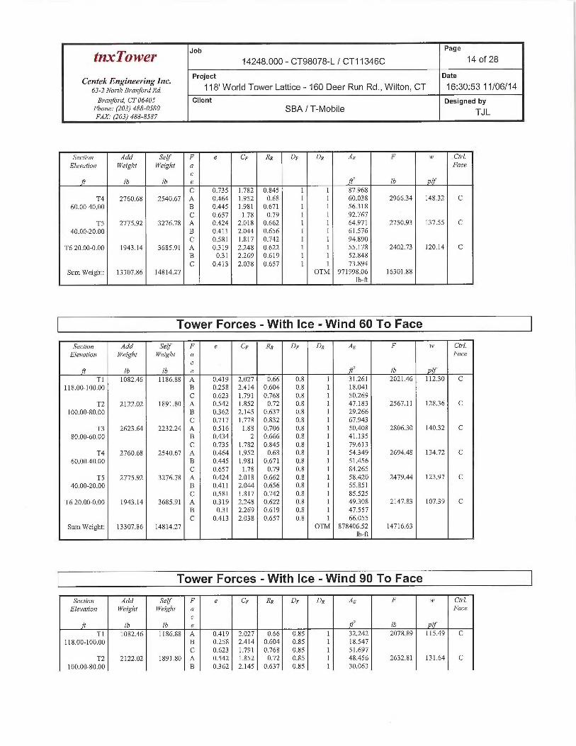
Job Page
tnx~'ower 14248.000 - CT98078-L / CT11346C 14 of 28
Centek Engineering bic. Project Date
63-allo~~r~, B,-a»fo~~axa. 118' World Tower Lattice - 160 Deer Run Rd., Wilton, CT 16:30:53 11/06/14
Branford, CT 06405 Client Designed byPlio~7e: (203) 488-0580 SBA / T-MobileFAX. (203) 488-8587 TJ L
Section Add Self F e CF Rx DF DR Ae F tai Ch~l.
Elevatim~ l~~eigl~t id~eigl~t a Facec
ft Ib lb e fY' Ib pIf
C 0.735 1.782 0.845 1 1 87.968T4 2760.68 2540.67 A 0.464 1.952 0.68 1 1 60.038 2966.34 14832 C
60.000.00 B 0.445 1.981 0.671 1 1 56.318C 0.657 1.78 0.79 1 1 92.767
TS 2775.92 3276.78 A 0.424 2.018 0.662 1 1 64.971 2750.93 137.55 C40.00-20.00 B 0.411 2.044 0.656 1 1 61.576
C 0.581 1.817 0.742 1 1 94.890T6 20.00-0.00 1943.14 3685.91 A 0319 2.248 0.622 1 1 55.178 2402.73 120.14 C
B 031 2.269 0.619 1 1 52.848C 0.413 2.038 0.657 1 1 73.894
Sum Weight: 13307.86 14814.27 OTM 971998.06 16301.88lb-ft
Tower Forces -With Ice -Wind 60 To Face
Section Add Self F e CF RR DF DR AE F iv Ch•1.Elevatio» T~i~eigltt Weight a Face
cft Ib Ib e ft' lb If
T1 1082.46 1186.88 A 0.419 2.027 0.66 0.8 1 31.261 2021.46 112.30 C118.00-100.00 B 0.258 2.414 0.604 0.8 1 18.041
C 0.623 1.791 0.768 0.8 1 50.269T2 2122.02 1891.80 A 0.542 1.852 0.72 0.8 1 47.183 2567.11 12836 C
100.00-80.00 B 0362 2.145 0.637 0.8 1 29.266C 0.717 1.778 0.832 0.8 1 67.943
T3 2623.64 2232.24 A 0.516 1.88 0.706 0.8 1 50.408 280630 140.32 C80.00-60.00 B 0.434 2 0.666 0.8 1 41.135
C 0.735 1.782 0.845 0.8 1 79.613T4 2760.68 2540.67 A 0.464 1.952 0.68 0.8 1 54.349 2694.48 134.72 C
60.00-40.00 B 0.445 1.981 0.671 0.8 1 51.456C 0.657 1.78 0.79 0.8 1 84.265
TS 2775.92 3276.78 A 0.424 2.018 0.662 0.8 1 58.420 2479.44 123.97 C40.00-20.00 B 0.411 2.044 0.656 0.8 1 55.851
C 0.581 1.817 0.742 0.8 1 85.525T6 20.00-0.00 1943.14 3685.91 A 0319 2.248 0.622 0.8 1 49.308 2147.83 10739 C
B 031 2.269 0.619 0.8 1 47.557C 0.413 2.038 0.657 0.8 1 66.055
Sum Weight: 13307.86 14814.27 OTM 878406.52 14716.63Ib-ft
Tower Forces -With Ice -Wind 90 To Face
Sectro~7 Add Self F e CF RR DF D2 AE F i~~ Ch~l.Elevation i~eigbt IT'eight a Face
cft Ib lb e ft' Ib plf
T1 1082.46 1186.88 A 0.419 2.027 0.66 0.85 1 32.242 2078.89 115.49 C118.00-100.00 B 0.258 2.414 0.604 0.85 1 18.547
C 0.623 1.791 0.768 0.85 1 51.697T2 2122.02 1891.80 A 0.542 1.852 0.72 0.85 1 48.456 2632.81 131.64 C
100.00-80.00 B 0.362 2.145 0.637 0.85 1 30.063

Job Page
tnxTower 14248.000 - CT98078-L / CT11346C 15 of 28
Centek E~zgineering bzc. Project Date
63-zNo~~r~,B,~a,~fo~~ana. 118' Worid Tower Lattice - 160 Deer Run Rd., Wilton, CT 16:30:53 11/06/14
Branford, CT 06405 Client Designed byPho~ae: (203) 488-0580 SBA / T-MobileFAX. (203) 488-8587 TJ L
Sectim~ Add Self F e CF Rn DF DR AE F i~~ Ct~-1.Elei~ation T~'eighl N~eight a Face
cft Tb Ib e f1' Ib plf
C 0.717 1.778 0.832 0.85 1 69.681T3 2623.64 2232.24 A 0.516 1.88 0.706 0.85 1 51.793 2879.93 144.00 C
80.00-60.00 B 0.434 2 0.666 0.85 1 42314C 0.735 1.782 0.845 0.85 1 81.702
T4 2760.68 2540.67 A 0.464 1.952 0.68 0.85 1 55.771 2762.45 138.12 C60.00-40.00 B 0.445 1.981 0.67] 0.85 1 52.671
C 0.657 1.78 0.79 0.85 1 86390TS 2775.92 3276.78 A 0.424 2.018 0.662 0.85 1 60.057 254731 127.37 C
40.00-20.00 B 0.411 2.044 0.656 0.85 1 57.282C 0.581 1.817 0.742 0.85 1 87.866
T6 20.00-0.00 1943.14 3685.91 A 0319 2.248 0.622 0.85 I 50.775 2211.55 110.58 CB 031 2.269 0.619 0.85 1 48.879C 0.413 2.038 0.657 0.85 1 68.015
Sum Weight: 13307.86 14814.27 OTM 901804.41 15112.94Ib-ft
Tower Forces -Service -Wind Normal To Face
Section Add Self F e CF RR DF DR AE F i~~ Cb•l.Elei~ation YYeight N'eigltf a Face
cft Ib lb e fY lb plf
T1 414.68 750.28 A 0.296 2307 0.615 l 1 22.385 673.32 37.41 C118.00-100.00 B 0.168 2.708 0.584 1 1 14.157
C 0.429 2.009 0.664 1 1 32362T2 828.48 1436.23 A 0394 2.076 0.649 1 1 32.560 805.53 40.28 C
100.00-80.00 B 0.252 2.431 0.602 1 1 21.152C 0.507 1.891 0.701 1 1 43.449
T3 1024.91 1708.65 A 0.375 2.115 0.642 1 1 35.216 873.58 43.68 C80.00-60.00 B 0.305 2.281 0.618 1 1 28.722
C 0.521 1.874 0.708 1 1 51.076T4 1072.40 1983.27 A 0.331 2.217 0.626 1 1 37.615 864.63 43.23 C
60.00-40.00 B 0.298 2301 0.615 1 1 33.939C 0.455 1.965 0.676 1 1 53.088
TS 1077.80 2587.89 A 0.309 2.272 0.619 1 1 42.608 855.38 42.77 C40.00-20.00 B 0.282 2.344 0.611 1 1 39.161
C 0.411 2.043 0.656 1 1 56.868T6 20.00-0.00 754.46 2935.87 A 0.234 2.486 0.598 1 1 38.070 797.57 39.88 C
B 0.218 2.537 0.594 1 1 35.829C 0.295 2308 0.615 1 1 46.940
Sum Weight: 5172.73 11402.19 OTM 283907.80 4870.00]b-ft
Tower Forces -Service -Wind 60 To Face
Section Add Self F e CF RR DF DR AE F i~~ CIrJ.Elevntio» Weight N'eiglit a Face
cft Ib lb e ft~ lb If
T1 414.68 750.28 A 0.296 2.307 0.615 0.8 1 20362 631.22 35.07 C118.00-100.00 B 0.168 2.708 0.584 0.8 1 12.134

tnxTower Jib
Page
14248.000 - CT98078-L / CT11346C 16 of 28
Centek Engineering Inc. Project gate
63-2 North Branford Rd. ~ ~8' World Tower Lattice - 160 Deer Run Rd., Wilton, CT 16:30:53 11/06/14Bra~lfoT-d, CT 06405 Client Designed by
Phone: (203) 488-0580 SBA / T-MobileFAX.• (203) 488-8587 TJ L
Secfion Add Serf F e CF RR DF Dx AE F is Ctrl.Elevation Weiglal N~eigltt a Face
cft Ib Ib e fY Tb plf
C 0.429 2.009 0.664 0.8 1 30.339T2 828.48 1436.23 A 0394 2.076 0.649 0.8 1 30.650 770.12 38.51 C
100.00-80.00 B 0252 2.431 0.602 0.8 1 19.242C 0.507 1.891 0.701 0.8 1 41.540
T3 1024.91 1708.65 A 0375 2.115 0.642 0.8 1 32.982 83536 41.77 C80.00-60.00 B 0.305 2.281 0.618 0.8 1 26.487
C 0.521 1.874 0.708 0.8 1 48.841T4 1072.40 1983.27 A 0.331 2.217 0.626 0.8 1 35.233 825.84 41.29 C
60.00-40.00 B 0.298 2301 0.615 0.8 1 31.557C 0.455 1.965 0.676 0.8 1 50.706
TS 1077.80 2587.89 A 0309 2.272 0.619 0.8 1 39.364 806.57 40.33 C40.00-20.00 B 0.282 2344 0.611 0.8 1 35.916
C 0.411 2.043 0.656 0.8 1 53.623T6 20.00-0.00 754.46 2935.87 A 0.234 2.486 0.598 0.8 1 34.515 737.17 36.86 C
B 0.218 2.537 0.594 0.8 1 32.274C 0.295 2.308 0.615 0.8 1 43.385
Sum Weight: 5172.73 11402.19 OTM 269449.62 4606.28Ib-ft
Tower Forces -Service -Wind 90 To Face
Section Add Self F e CF RR DF DR AE F i~~ Cirl.Elevatio» T~reight YPeight a Face
cf1 lb Ib e ft' Ib if
T1 414.68 750.28 A 0.296 2307 0.615 0.85 1 20.868 641.74 35.65 C118.00-100.00 B 0.168 2.708 0.584 0.85 1 12.639
C 0.429 2.009 0.664 0.85 1 30.845T2 828.48 1436.23 A 0.394 2.076 0.649 0.85 1 31.127 778.97 38.95 C
100.00-80.00 B 0.252 2.431 0.602 0.85 1 19.720C 0.507 1.891 0.701 0.85 1 42.017
T3 1024.91 1708.65 A 0375 2.115 0.642 0.85 1 33.540 844.91 42.25 C80.00-60.00 B 0305 2.281 0.618 0.85 1 27.046
C 0.521 1.874 0.708 0.85 1 49.400T4 1072.40 1983.27 A 0.331 2.217 0.626 0.85 1 35.828 835.54 41.78 C
60.00-40.00 B 0.298 2.301 0.615 0.85 1 32.153C 0.455 1.965 0.676 0.85 1 51302
TS 1077.80 2587.89 A 0.309 2.272 0.619 0.85 1 40.175 818.77 40.94 C40.00-20.00 B 0.282 2.344 0.611 0.85 1 36.727
C 0.411 2.043 0.656 0.85 1 54.434T6 20.00-0.00 754.46 2935.87 A 0.234 2.486 0.598 0.85 1 35.403 752.27 37.61 C
B 0.218 2.537 0.594 0.85 1 33.163C 0.295 2308 0.615 0.85 1 44.274
Sum Weight: 5172.73 11402.19 OTM 273064.16 4672.21lb-ft
Force Totals

Job Page
tfZ~TOW~~' 14248.000 - CT98078-L / CT11346C 17 of 28
Ceiztek Engineering Inc. Project Date
63-2 NorthBra»fordRd. ~ ~H' World Tower Lattice - 160 Deer Run Rd., Wilton, CT 16:30:53 11/06/14Branford, CT 06405 Client Designed by
Pho~ze: (203) 488-0580 SBA I T-MobileFAX.• (203) 488-8587 TJ L
Load T/ertical Sunr of Sven of Sum of Sann of Szn~r of TorquesCase Forces Fm•ces Forces Overturning Onerturrai~ag
X Z Mome~7ts, M Moments, M,Tb Ib lb lb ft Tb ft Ib-ft
Leg Weight 7763.98Bracing Weight 3638.21 __Total Member Self-Weight 11402.19 4172.23 4372.12Total Weight 2201839 4172.23 4372.12WindO deg -No Ice 0.00 -22907.91 -1704634.66 4372.12 -5888.14Wind 30 deg - No Ice 11173.70 -19343.79 -1448558.34 -834973.60 -209731Wind 60 deg - No Ice 19188.40 -11072.87 -829339.14 -1440370.78 2018.76Wind 90 deg - No Ice 22347.40 0.00 4172.23 -167431933 5636.18Wind 120 deg - No Ice 19848.46 11453.95 858575.67 -1476556.92 8004.54Wind 150 deg - No Ice 11173.70 19343.79 1456902.80 -834973.60 7733.48Wind 180 deg - No Ice 0.00 22145.74 1671194.97 4372.12 5605.03Wind 210 deg - No Ice -11173.70 19343.79 1456902.80 843717.84 209731Wind 240 deg - No Ice -19848.46 11453.95 858575.67 1485301.16 -2116.40Wind 270 deg - No Ice -22347.40 0.00 4172.23 1683063.57 -5636.18Wind 300 deg - No Ice -19188.40 -11072.87 -829339.14 1449115.02 -7623.79Wind 330 deg - No Ice -11173.70 -19343.79 -144855834 843717.84 -7733.48Member Ice 3412.08 _ _ __Total Weight Ice 36374.93 11221.96 11123.57Wind 0 deg -Ice 0.00 -24317.80 -1753016.51 11123.57 -4278.01Wind 30 deg -Ice ] 1568.79 -20030.18 -1455863.89 -836378.19 -762.26Wind 60 deg -Ice 19694.51 -11366.28 -824101.51 -1436529.38 2646.82Wind 90 deg -Ice 23137.58 0.00 11221.96 -1683879.96 5441.17Wind 120 deg -Ice 21067.38 12158.90 893341.19 -1517582.03 7143.04Wind 150 deg -Ice 1 1568.79 20030.1 S 1478307.80 -836378.19 6203.44Wind 180 deg -Ice 0.00 22732.55 1681868.89 11123.57 3936.19Wind 210 deg -Ice -11568.79 20030.18 1478307.80 858625.34 762.26Wind 240 deg -Ice -2106738 12158.90 893341.19 1539829.18 -2865.03Wind 270 deg -Ice -23137.58 0.00 11221.96 1706127.11 -5441.17Wind 300 deg -Ice -19694.51 -11366.28 -824101.51 1458776.53 -6583.01Wind 330 deg -Ice -11568.79 -20030.18 -1455863.89 858625.34 -6203.44Total Weight 2201839 4172.23 4372.12Wind 0 deg -Service 0.00 -7926.61 -59118631 81.47 -2037.42Wind 30deg-Service 386633 -669335 -502578.59 -290349.58 -725.71Wind 60 deg -Service 6639.58 -3831.44 -288315.89 -499829.57 698.53Wind 90 deg -Service 7732.66 0.00 9635 -580780.63 1950.23Wind 120 deg -Service 6867.98 3963.31 295737.68 -512350.73 2769.74Wind 150 deg -Service 386633 6693.35 502771.29 -290349.58 2675.95Wind 180 deg -Service 0.00 7662.89 576920.83 81.47 1939.46Wind 210 deg -Service -386633 669335 502771.29 290512.51 725.71Wind 240 deg -Service -6867.98 3963.31 295737.68 512513.66 -732.32Wind 270 deg -Service -7732.66 0.00 9635 580943.56 -1950.23Wind 300 deg -Service -6639.58 -3831.44 -288315.89 499992.51 -2637.99Wind 330 de -Service -3866.33 -6693.35 -502578.59 290512.51 -2675.95
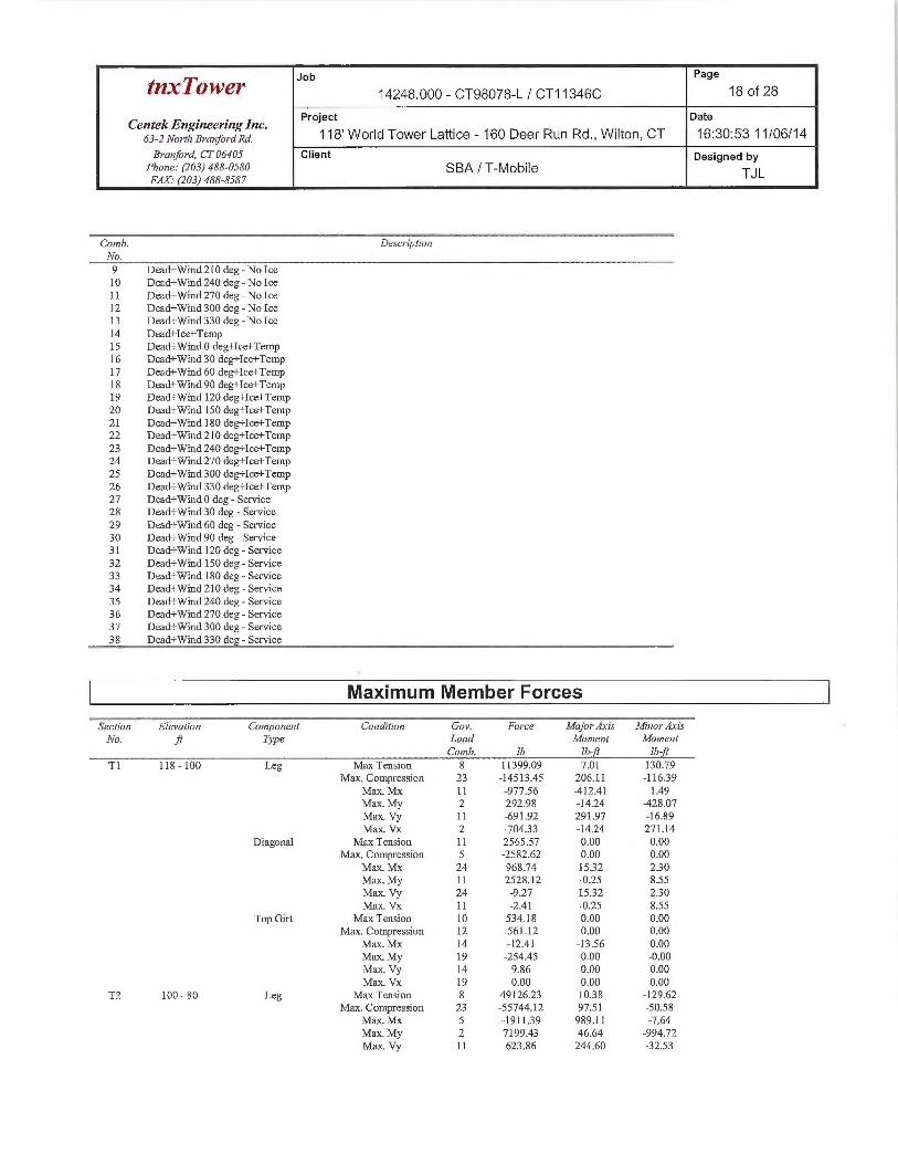
Load Combinations
Comb. DescriptionNo.
1 Dead Only2 Dead+Wind 0 deg - No Ice3 Dead+Wind 30 deg - No Ice4 Dead+Wind 60 deg - No Ice5 Dead+Wind 90 deg - No Ice6 Dead+Wind 120 deg - No Ice7 Dead+Wind 150 deg - No Ice8 Dead+Wind 180 deg - No Ice
Job Page
tnxTowe~ 14248.000 - CT98078-L / CT11346C 18 of 28
CentekEngineeringlnc. Project Date
63-2 North Branford Rd. ~ ~$' World Tower Lattice - 160 Deer Run Rd., Wilton, CT 16:30:53 11/06/14
Branford, CT 06405 Client Designed byPhone: (203)488-0580 SBA / T-Mobile TJLFAX.• (203) 488-8587
Camb. Descriptio~aNo.9 Dead+Wind 210 deg-No Ice10 Dead+Wind 240 deg-No IceI 1 Dead+Wind 270 deg - No Ice12 Dead+Wind 300 deg - No Ice13 Dead+Wind 330 deg-No Ice14 Dead+Ice+Temp15 Dead+Wind 0 deg+Ice+Temp16 Dead+Wind 30 deg+Ice+Temp17 Dead+Wind 60 deg+Ice+Temp18 Dead+Wind90 deg+Ice+Temp19 Dead+Wind 120 deg+Ice+Temp20 Dead+Wind 150 deg+Ice+Temp21 Dead+Wind 180 deg+Ice+Temp22 Dead+Wind 210 deg+Ice+Temp23 Dead+Wind 240 deg+Ice+Temp24 Dead+Wind 270 deg+Ice+Temp25 Dead+Wind 300 deg+Ice+Temp26 Dead+Wind 330 deg+Ice+Temp27 Dead+Wind 0 deg -Service28 Dead+Wind 30 deg -Service29 Dead+Wind 60 deg -Service30 Dead+Wind 90 deg -Service31 Dead+Wind 120 deg -Service32 Dead+Wind 150 deg -Service33 Dead+Wind 180 deg -Service34 Dead+Wind 210 deg -Service35 Dead+Wind 240 deg -Service36 Dead+Wind 270 deg -Service37 Dead+Wind 300 deg -Service38 Dead+Wind 330 deg -Service
Maximum Member Forces
Section Elevation Component Condition Gov. Force Majorllxis MinarAzisNo. ft Type Load Moment Moment
Gomb. Ib Ib ft ]b-ftTl 118 -100 Leg Max Tension 8 11399.09 7.01 130.79
Max, Compression 23 -14513.45 206.11 -116.39Max. M1c 11 -977.56 -412.41 1.49Max. My 2 292.98 -14.24 -428.07Max. Vy I1 -691.92 291.97 -16.89Max. Vx 2 -70433 -14.24 271.14
Diagonal Mas Tension 11 2565.57 0.00 0.00Max. Compression 5 -2582.62 0.00 0.00
Max. Mac 24 968.74 15.32 230Max. My 11 -2528.12 -0.25 8.55Max. Vy 24 -9.27 1532 2.30Max Vx 11 -2.41 -0.25 8.55
Top Gut Max Tension 10 534.18 0.00 0.00Max. Compression 12 -561.12 0.00 0.00
Max. NUc 14 -12.41 -13.56 0.00Max. My 19 -254.45 x.00 -0.00Max. Vy 14 9.86 0.00 0.00Max. Vx 19 0.00 0.00 0.00
T2 100 - 80 Leg Max Tension 8 49126.23 10.38 -129.62Max. Compression 23 -55744.12 97.51 -50.58
Max. M1c 5 -191139 989.11 -7.64Max. My 2 71.99.43 46.64 -994.72Max. Vy 11 623.86 244.60 -32.53

Pa e
tnxTowe~ Job 14248.000 - CT98078-L / CT11346C 9 19 of 28
CentekEngineeringlnc. Project gate
63-2 NorthBranfoYaxa. 118' World Tower Lattice - 160 Deer Run Rd., Wilton, CT 16:30:53 11/06/14
Branford, CT 06405 Client Designed byPhone: (203) 488-0580 SBA / T-Mobile TJLFAX.• (203) 488-8587
Section Elevation Component Condition Gov. Force Major Axis Mi~aorAsis
No. fl Type Laad Monae~at MomentComb. Ib lb-ft Zb ft
Max. Vx 2 629.46 -13.48 262:64Diagonal Max Tension 11 5615.26 0.00 0.00
Ma1c. Compression 11 -5705.94 0.00 0.00Max. Mx 23 4448.78 24.50 -.1.48Max. My 7 -4963.99 -832 -8.57Max. Vy 23 -12.65 24.50 -1.48Max. Vx 7 231 -8.32 -8.57
T3 80 - 60 Leg Max Tension 8 82662:53 -88.79 -24,30Max. Compression 23 -93440.02 82.29 4.77
Max. Mx 21 76937.86 -172..69 29.12MaJc. My 9 -2863.99 -13.70 190.89Max. Vy IS 66.28 103.13 25.08Max. Vx 22 101.85 17.26 130.05
Diagonal Ma:c Tension 18 4175.34 0.00 0.00Mas. Compression 18 11113.89 0.00 0.00
Max. Mx 23 3268.85 22.88 2.00Max My 12 -3444.35 -1.79 7.68Max. Vy 23 -12.66 22.17 1.40Max.. Vx 12 -2.19 0.00 0.00
Top Gut Max Tension 23 64.84 0.00 0.00Max. Compression 12 -158.44 0.00 0.00
Max. Mx 14 -18.02 -13.55 0.00Max. My 19 -76.13 0.00 0.29Max. Vy 14 9.86 0.00 0.00Max. Vx 19 -0.21 0.00 0.00
T4 60 - 40 Leg Max Tension 8 110891.51 -115.06 3.68Maas. Compression 23 -128045.98 -175.85 12.98
Maz. MJc 23 -11908317 292.12 3.17Max. My 26 -9788.05 -131.99 273.98Max. Vy 17 -163.73. -169.73 -5.08Max. Vx 20 -171.14 -41.65 -50.46
Diagonal Max Tension 18 4766.84 0.00 0.00Max. Compression 18 -4808.64 0.00 O.OQ
Max. Mac 23 3313.55 26.72 1.22Max. My 19 -399419 -7.54 -4:22Max. Vy 23 -1.4.32 26.72 1.22Max. Vx 19 1.10 0.00 0.00
TS 40 - 20 Leg Max Tension 8 132670.40 20637 -18.93Max. Compression 23 -15596898 -495.50 12.47
Ma1c. Mac 23 -155713.70 672.47 -10.26Max. My 7 -6182.72 -12.07 -754.09Max. Vy 23 234.49 672.47 -10.26Max. Vx 7 -240.86 -12.07 -754.09
Diagonal Max Tension 18 6269.62 0.00 0.00Max. Compression 18 -6563.78 0.00 0.00
Max. Mx 21 4116.64 112.67 4.16Max. My 24 -6456.99 -15.50. 28.59Max. Vy 21 33.82 112.67 4.16Max. Vx 24 X4.99 0.00 0.00
Secondary Ma7c Tension 25 366.12 0.00 0.00Horizontal
Max. Compression 10 -345.15 0.00 0.00Max. Mx 14 36.10 -4139 0.00Max. My 19 138.99 0.00 0.90Max. Vy 14 17.23 0.00 0.00Max. Vx 19 -037 0.00 0.00
T6 20 - 0 Leg Max Tension 8 155510.78 204.94 -16.37Max. Compression 23 -185262.84 -0.00 -0.02
Max. Mx 10 -160886.86 675.85 -1.08Max. My 7 -7118.72 -17.65 -945.46Max. Vy 23 -252.89 671.20 -3.08

Page
tT~w~r Job 14248.000 - CT98078-L / CT11346C 20 of 28
CentekEngineeringlnc. Project gate
632NorthBranfordRd. ~ ~$' World Tower Lattice - 160 Deer Run Rd., Wilton, CT 16:30:53 11/06/14
Branford, CT 06405 Client Designed byPharre: (203) 488-0580 SBA / T-MobileFAX.• (203) 488-8587
TJ L
Seciioi~ Elevation Co»vpa~7ent Conditio» Goi~. Force MajorAsis MiraorAxisJ
Na ft Tj~e Load Moment MomentComb. Ib Ib ft Ib ft
Max. Vx 7 -274.64 -17.64 -945.46
Diagonal Max Tension 18 6163.93 0.00 0.00Max. Compression 18 -6354.83 0.00 0.00
Maac.IvlY 21 3898.26 121.23 2.48
Max. My 24 -6248.61 12,91 26.46Max. Vy 21 36.71 121.23 2.48Max. Vx 24 -4.38 0.00 0.00
Secondary Max Tension 8 405.40 0.00 0.00Horizontal
Max. Compression 23 -424.14 0.00 0.00
Max. Mx 14 -33.43 -55.33 0.00Max. My 25 -228.24 0.00 1.20Max. Vy 14 -19.92 0.00 0.00
Max. Vx 25 -0.43 0.00 0.00
Maximum Reactions
Location Conditio~a Gov. Yertica7 Horizontal, X Horizo~atal, Z
Load Ib Ib Ib
LegC Max. Vert 23 191875.38 12604.59 -7104.57Max. Hx 23 19187538 12604.59 -7104.57Max. Hz 16 -134507.51 -9939.05 6693.29
Min. Vert 4 -160152.68 -11157.00 6323.82
Min. Hx 17 -155094.07 -11800.79 6662.22Min. H~ 23 191875.38 12604.59 -7104.57
Legg Max. Vert 19 189927.31 -1269836 -6892.54
Max. Hx 25 -15704338 11916.24 6510.21
Max. H~ 25 -1:5704338 1191624 6510.21
Min. Vert 12 -160916.86 11306.05 6083.92
Min. Hx 19 189927.31 -12698.36 -6892.54
Min. H~ 19 189927.31 -1269836 -6892.54
Leg A Max. Vert 15 189127.04 -230.46 14429.75
Max. Hx 24 10990.64 1349.84 -I 16.21
Max. H~ 15 189127.04 -230.46 14429.75Min. Vert 8 -161073.23 282.32 -12831.05
Min. Hx 18 10989.40 -1378.22 -113.07Min. H,; 21 -157696.76 18939 -13579.80
Tower Mast Reaction Summary
Load Vertical Shearr Shear_ Ove~•turning Overtm~~aing Torque
Combination Mo»vent, M Mor~7ent, M,Ib Ib Ib Tb ft Ib ft Tb-fi
Dead Only 22018.39 0.00 -0.00 4172.21 4372.11 0.00
Dead+Wind 0 deg -No Ice 22018.38 -0.10 -22907.94 -1710800.41 4412.54 -5913.20
Dead+Wind 30 deg-No Ice 2201837 11173.30 -19343.95 -1453814.82 -837995.51 -2094.48
Dead+Wind 60 deg -No Ice 22018.40 19188.40 -11072.84 -832345.57 -1445604.74 2025.13
Dead+Wind 90 deg -No Ice 22018.37 2234733 0.50 4204.04 -1680392.00 5644.41
Dead+Wind 120 deg - No Ice 22018.38 19848.41 11454.11 861706.67 -1481885.48 8035.63
Dead+Wind 150 deg -No Ice 22018.38 11173.94 19343.60 1462204.28 -837977.24 7781.02
Dead+Wind 180 deg - No Ice 22018.40 -0.06 22145.72 1677271.23 4407.00 5630.60
Dead+Wind 210 deg-No Ice 2201837 -11174.05 19343.51 1462189.13 846785.88 2094.07

Job Page
tnxTowe~ 14248.000 - CT98078-L / CT11346C 21 of 28
Centek Engineering bzc. Project Date
63-allo~~r~,B,~a~,fo~~ana. 118' World Tower Lattice - 160 Deer Run Rd., Wilton, CT 16:30:53 11/06/14
Branford, CT 06405 Client Designed byPhone: (203) 488-0580 SBA / T-MobileFAX. (203) 488-8587 TJ L
~r _ Load Ver•/ical Slaearr ~ Shears Overturni»g ~ Overtur~aing-- ----- TorgueTi4_Combinafion Moment, M Moment, M
Ib Ib lb Ib-ft Ib-ft Ib-ft
Dead+Wind 240 deg - No Ice 22018.38 -19848.46 11454.02 861686.19 1490676.05 -2121.46Dead+Wind 270 deg - No Ice 2201837 -2234733 0.51 4199.12 1689175.54 -5643.99Dead+Wind 300 deg - No Ice 22018.40 -19188.43 -11072.79 -832334.72 1454399.05 -7654.77Dead+Wind 330 deg - No Ice 2201838 -11173.41 -19343.90 -1453798.58 846808.21 -7780.98
Dead+Ice+Temp 36374.93 -0.00 0.00 11280.98 11192.57 -0.00Dead+Wind 0 deg+Ice+Temp 36374.91 0.00 -24317.66 -1762815.26 11252.46 -4346.90Dead+Wind 30 deg+Ice+Temp 36374.91 11568.24 -20030.46 -1463993.15 -841036.71 -775.89Dead+Wind 60 deg+Ice+Temp 36374.93 19694.54 -11366.21 -828701.74 -1444567.87 2663.57Dead+Wind 90 deg+Ice+Temp 36374.90 23137.53 0.77 11309.40 -1693281.92 5483.04Dead+Wind 120 deg+Ice+Temp 36374.91 21067.28 12158.80 898420.20 -1526023.74 7230.88
Dead+Wind 150 deg+Ice+Temp 36374.91 11569.20 20029.92 148659838 -84102138 6302.87Dead+Wind 180 deg+Ice+Temp 36374.93 -0.09 22732.54 1691304.24 11212.60 4000.44Dead+Wind 210 deg+Ice+Temp 36374.90 -1156934 20029.82 1486580.48 863441.46 774.76Dead+Wind 240 deg+Ice+Temp 36374.91 -21067.27 12158.80 898373.49 1548453.58 -2883.17Dead+Wind 270 deg+Ice+Temp 36374.90 -23137.53 0.81 11297.13 1715688.85 -5481.99Dead+Wind 300 deg+Ice+Temp 36374.93 -19694.58 -11366.13 -828700.75 1466985.54 -6663.23Dead+Wind 330 deg+Ice+Temp 36374.91 -1156836 -20030.40 -1463987.44 86347139 -6302.67Dead+Wind 0 deg -Service 2201839 -0.00 -7926.61 -589242.28 4394.97 -2046.56Dead+Wind 30 deg -Service 22018.39 386633 -6693.35 -500315.64 -287094.17 -730.93Dead+Wind 60 deg -Service 2201839 6639.58 -3831.44 -285273.63 -497342.73 700.84Dead+Wind 90 deg -Service 2201839 7732.66 0.01 4192.87 -578584.78 1959.26Dead+Wind 120 deg -Service 22018.39 6867.98 396331 300908.39 -509901.83 2781.15Dead+Wind 150 deg -Service 2201839 3866.33 6693.35 508695.17 -287095.23 2687.29Dead+Wind 180 deg -Service 2201839 -0.00 7662.88 583117.91 439335 1949.00Dead+Wind 210 deg -Service 22018.39 -386634 669335 508692.70 295881.17 730.89
Dead+Wind 240 deg -Service 22018.39 -6867.98 396331 300905.00 518686.21 -734.49Dead+Wind 270 deg -Service 2201839 -7732.66 0.01 4191.16 587368.86 -1959.22Dead+Wind 300 deg -Service 2201839 -6639.58 -3831.44 -285273.31 506128.58 -2649.76Dead+Wind 330deg-Service 2201839 -3866.33 -669335 -500314.56 295882.55 -2687.29
Solution Summary
Sunt of Applied Forces Sznn ofReactio~tsLoad PX PY PZ PX PY PZ %Error-
Comb. lb lb Ib Tb lb Ib
1 0.00 -2201839 -0.00 -0.00 2201839 0.00 0.000%2 0.00 -22018.39 -22907.91 0.10 22018.38 22907.94 0.000%
3 11173.70 -22018.39 -19343.79 -1117330 22018.37 19343.95 0.001%4 19188.40 -2201839 -11072.87 -19188.40 22018.40 11072.84 0.000%5 22347.40 -2201839 -0.00 -22347.33 2201837 -0.50 0.002%6 19848.46 -22018.39 11453.95 -19848.41 2201838 -11454.11 0.001%
7 11173.70 -2201839 19343.79 -11173.94 22018.38 -19343.60 0.001%8 0.00 -22018.39 22145.74 0.06 22018.40 -22145.72 0.000%
9 -11173.70 -22018.39 19343.79 11174.05 2201837 -19343.51 0.001%10 -19848.46 -2201839 11453.95 19848.46 2201838 -11454.02 0.000%11 -22347.40 -2201839 -0.00 22347.33 2201837 -0.51 0.002%12 -19188.40 -22018.39 -11072.87 19188.43 22018.40 11072.79 0.000%13 -11173.70 -2201839 -19343.79 11173.41 2201838 19343.90 0.001%14 0.00 -36374.93 -0.00 0.00 36374.93 -0.00 0.000%
15 0.00 -36374.93 -24317.80 -0.00 36374.91 24317.66 0.000%16 11568.79 -36374.93 -20030.18 -11568.24 36374.91 20030.46 0.001%
17 19694.51 -36374.93 -11366.28 -19694.54 36374.93 11366.21 0.000°/a18 23137.58 -36374.93 -0.00 -23137.53 36374.90 -0.77 0.002%19 2106738 -36374.93 12158.90 -21067.28 36374.91 -12158.80 0.000%20 11568.79 -36374.93 20030.18 -11569.20 36374.91 -20029.92 0.001%21 0.00 -36374.93 22732.55 0.09 36374.93 -22732.54 0.000%22 -11568.79 -36374.93 20030.18 11569.34 36374.90 -20029.82 0.002%23 -2106738 -36374.93 12158.90 21067.27 36374.91 -12158.80 0.000%

Job Page
tnxTower 14248.000 - CT98078-L / CT11346C 22 of 28
Centek Engineering Lzc. Project Date
63-2Nortl~Branford Rd. ~ ~H' World Tower Lattice - 160 Deer Run Rd., Wilton, CT 16:30:53 11/06/14
Branfo~•d, CT 06405 Client Designed byPl~o~7e: (203) 488-0580 SBA / T-Mobile TJLFAX.• (203) 488-8587
Szm~ of Applied Forces Su»~ ofReactio»s
Load PX PY PZ PX PY PZ %Error
Conrb. Ib Ib Ib Ib Ib Ib
24 -23137.58 -36374.93 -0.00 23137.53 36374.90 -0.81 0.002%
25 -19694.51 -36374.93 -11366.28 19694.58 36374.93 11366.13 0.000%
26 -11568.79 -36374.93 -20030.18 1156836 36374.91 20030.40 0.001%
27 0.00 -2201839 -7926.61 0.00 2201839 7926.61 0.000%
28 386633 -2201839 -669335 -3866.33 2201839 669335 0.000%
29 6639.58 -22018.39 -3831.44 -6639.58 22018.39 3831.44 0.000°/a
30 7732.66 -2201839 -0.00 -7732.66 22018.39 -0.01 0.000°/a
31 6867.98 -2201839 396331 -6867.98 2201839 -396331 0.000%
32 386633 -2201839 6693.35 -3866.33 2201839 -669335 0.000%
33 -0.00 -2201839 7662.89 0.00 22018.39 -7662.88 0.000%
34 -386633 -2201839 6693.35 386634 2201839 -6693.35 0.000%
35 -6867.98 -22018.39 3963.31 6867.98 2201839 -396331 0.000%
36 -7732.66 -22018.39 -0.00 7732.66 2201839 -0.01 0.000%
37 -6639.58 -2201839 -3831.44 6639.58 2201839 3831.44 0.000%
38 -3866.33 -22018.39 -669335 386633 22018.39 669335 0.000°/a
Non-Linear Convergence Results
Load Co~aver•ged? Ntmaber• Displacerne»t Force
Conibiraatio~a ofG~~cles Tolerance To]erance
1 Yes 4 0.00000001 0.0000000]
2 Yes 4 0.00000001 0.00000622
3 Yes 4 0.00000001 0.00001436
4 Yes 4 0.00000001 0.00000799
5 Yes 4 0.00000001 0.00001547
6 Yes 4 0.00000001 0.00000654
7 Yes 4 0.00000001 0.00001266
8 Yes 4 0.00000001 0.00000819
9 Yes 4 0.00000001 0.00001464
10 Yes 4 0.00000001 0.00000616
11 Yes 4 0.00000001 0.00001570
12 Yes 4 0.00000001 0.00000832
13 Yes 4 0.00000001 0.00001261
14 Yes 4 0.00000001 0.00000001
15 Yes 4 0.00000001 0.00000842
16 Yes 4 0.00000001 0.00001344
17 Yes 4 0.00000001 0.00000511
18 Yes 4 0.00000001 0.00001496
19 Yes 4 0.00000001 0.00000857
20 Yes 4 0.00000001 0.00001277
21 Yes 4 0.00000001 0.00000535
22 Yes 4 0.00000001 0.00001417
23 Yes 4 0.00000001 0.00000877
24 Yes 4 0.00000001 0.00001553
25 Yes 4 0.00000001 0.00000552
26 Yes 4 0.00000001 0.00001260
27 Yes 4 0.00000001 0.00000001
28 Yes 4 0.00000001 0.00000001
29 Yes 4 0.00000001 0.00000001
30 Yes 4 0.00000001 0.00000001
31 Yes 4 0.00000001 0.00000001
32 Yes 4 0.00000001 0.00000001
33 Yes 4 0.00000001 0.00000001
34 Yes 4 0.00000001 0.00000001
35 Yes 4 0.00000001 0.00000001
36 Yes 4 0.00000001 0.00000001
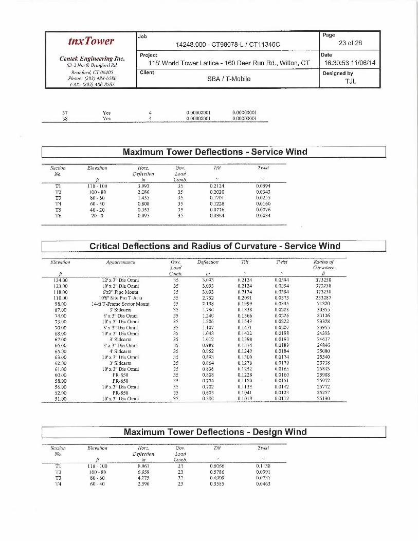
Job Page
t~xTower 14248.000 - CT98078-L / CT11346C 23 of 28
Centek Engineering Inc. Project Date
63-2 Nortl~BrarTfordRd. ~ ~8' Worid Tower Lattice - 160 Deer Run Rd., Wilton, CT 16:30:53 11/06/14
Branford, CT 06405 Client Designed byPhone: (203) 488-0580 SBA / T-Mobile TJLFAX. (203) 488-8587
37 Yes 4 0.00000001 0.0000000138 Yes 4 0.00000001 0.00000001
Maximum Tower Deflections -Service Wind
Section Elei~ation ~ Horz. Gov. Tilt ~~ W ~~ T~~ist
No. Deflection Loadft i~r Contb. °
TI 118 -100 3.093 35 0.2124 0.0394T2 100 - 80 2.286 35 0.2020 0.0343T3 80 - 60 1.455 35 0.1701 0.0255T4 60-40 0.808 35 0.1228 0.0160
TS 40-20 0353 35 0.0776 0.0076T6 20 - 0 0.095 35 0.0364 0.0034
Critical Deflections and Radius of Curvature -Service Wind
Elevation Appurtenrn~ce ~ Gov. Deflection Tilt Tmist Radius ofLoad Cu~vatw•e
ft Conab. i~r ft
124.00 12' x 3" Dia Omni 35 3.093 0.2124 0.0394 373258123.00 10' x 3" Dia Omni 35 3.093 0.2124 0.0394 373258
118.00 6'x3" Pipe Mount 35 3.093 0.2124 0.0394 373258110.00 10'6" Site Pro T-Arm 35 2.732 0.2091 0.0373 23328798.00 14-ft T-Frame Sector Mount 35 2.198 0.1999 0.0335 74320
87.00 3' Sidearm 35 1.730 0.1838 0.0288 30355
74.00 8' x 3" Dia Omni 35 1.240 0.1566 0.0226 2312673.00 10' x 3" Dia Omni 35 1.206 0.1543 0.0222 23328
70.00 8' x 3" Dia Omni 35 1.107 0.1471 0.0207 2395568.00 10' x 3" Dia Omni 35 1.043 0.1422 0.0198 2439367.00 3' Sidearm 35 1.012 0.1398 0.0193 24617
66.00 8' x 3" Dia Omni 35 0.982 0.1374 0.0189 24846
65.00 4' Sidearm 35 0.952 0.1349 0.0184 2508063.00 10' x 3" Dia Omni 35 0.893 0.1300 0.0174 25540
62.00 3' Sidearm 35 0.864 0.1276 0.0170 25738
61.00 10' x 3" Dia Omni 35 0.836 0.1252 0.0165 2589360.00 PR-850 35 0.808 0.1228 0.0160 2598858.00 PR-850 35 0.754 0.1180 0.0151 25972
56.00 10' x 3" Dia Omni 35 0.702 0.1133 0.0142 2577252.00 PR-850 35 0.603 0.1041 0.0123 25257
51.00 10' x 3" Dia Omni 35 0.580 0.1019 0.0119 25130
Maximum Tower Deflections -Design Wind
Section Elevatio» Harz. Gov. Tilt Twist
No. Deflectio~a Loadft i~t Comb. °
T1 118 - 100 8.961 23 0.6066 0.1138
T2 100 - 80 6.658 23 0.5786 0.0991T3 80 - 60 4.275 23 0.4909 0.0737T4 60-40 2396 23 0.3585 0.0463

tnxTower Jib
Page
14248.000 - CT98078-L / CT11346C 24 of 28
Centek E~Zgineering Inc. Project Date
63-2Nort7aBrar7fordRd. ~ ~ 8' World Tower Lattice - 160 Deer Run Rd., Wilton, CT 16:30:53 11/06/14B,~arafo,•d, CT 06405 Client Designed by
Pho~1e: (203) 488-0580 SBA / T-MOblle TJLFAX. (203) 488-8587
Sectro» Elevation Horz. Goi~. Tilt TmistNo. Deflectim~ Load
ft in Comb. °TS 40-20 1.053 23 0.2290 0.0221T6 20 - 0 0.285 23 0.1081 0.0099
Critical Deflections and Radius of Curvature -Design Wind
Elei~atior~ Appzn•tenance Gov. Deflecfio~7 Tilt Twist Radius ofLoad Curvature
ft Comb. i» ft
124.00 12' x 3" Dia Omni 23 8.961 0.6066 0.1138 136674123.00 10' x 3" Dia Omni 23 8.961 0.6066 0.1138 136674118.00 6'x3" Pipe Mount 23 8.961 0.6066 0.1138 136674110.00 10'6" Site Pro T-Arm 23 7.932 0.5978 0.1079 8542198.00 14-ft T-Frame Sector Mount 23 6.406 0.5729 0.0969 2678587.00 3' Sidearm 23 5.066 0.5288 0.0833 1069874.00 8' x 3" Dia Otani 23 3.653 0.4536 0.0655 811173.00 10' x 3" Dia Omni 23 3.554 0.4470 0.0641 818070.00 8' x 3" Dia Omni 23 3.267 0.4270 0.0600 839868.00 10' x 3" Dia Omni 23 3.082 0.4133 0.0573 854967.00 3' Sidearm 23 2.991 0.4065 0.0559 862766.00 8' x 3" Dia Omni 23 2.902 03996 0.0545 870665.00 4' Sidearm 23 2.815 0.3927 0.0532 878763.00 10' x 3" Dia Omni 23 2.643 0.3790 0.0504 894662.00 3' Sidearm 23 2.560 0.3721 0.0491 901461.00 10' x 3" Dia Omni 23 2.477 03653 0.0477 906760.00 PR-850 23 2396 03585 0.0463 909858.00 PR-850 23 2.238 03450 0.0436 908956.00 10' x 3" Dia Omni 23 2.084 03317 0.0409 901552.00 PR-850 23 1.793 0.3054 0.0356 882651.00 10' x 3" Dia Omni 23 1.724 0.2989 0.0343 8780
Bolt Design Data
Section Elevatio» Compo~ae~at Bolt Bolt Size Number Mazimim~ Al7ota~able Ralio ~ Alloia~able CriteriaNo. Type Grade Of Load per Load Load Ratio
ft in Bolts Bolt Ib Alloia~ableIb
T1 118 Leg A325N 0.7500 4 2849.77 19438.50 0.147 ~
1333 Bolt Tension
Diagonal A325N 0.6250 1 2565.57 4078.13 0.629 V
1.333 Member Bearing
Top Girt A325N 0.6250 1 534.18 4078.13 0.131 ~
1.333 Member Bearing
T2 100 Leg A325N 0.7500 4 12281.60 19438.60 0.632 ~
1333 Bolt Tension
Diagonal A325N 0.6250 1 5615.26 6117.19 0.918 ~
1333 Member Bearing
T3 80 Leg A325N 1.0000 4 20669.00 34557.50 0.598 4~
1.333 Bolt Tension
Diagonal A325N 0.6250 1 4175.34 6117.19 0.683 ~
1.333 Member Bearing
Top Gut A325N 0.6250 1 158.43 5437.50 0.029 f~
1333 Member Bearing
T4 60 Leg A325N 1.0000 4 27722.90 34557.50 ~ 802 ~ 1.333 Bolt Tension
Diagonal A325N 0.6250 I 4766.84 6117.19 ~ 779 ~ 1.333 Member Bearing
TS 40 Leg A325N 1.0000 6 22088.50 34557.50 0.639 ~
1.333 Bolt Tension
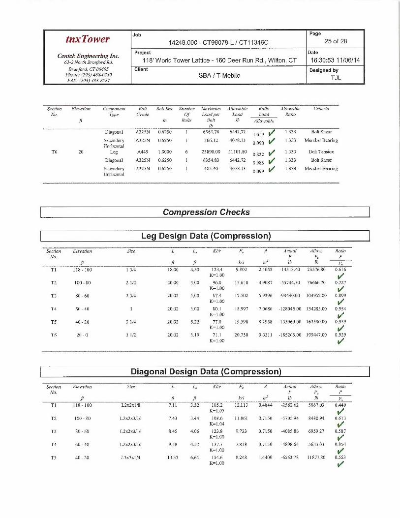
Job Page
tnxTower 14248.000 - CT98078-L / CT11346C 25 of 28
Ceiatek Engi~ieering Inc. Project Date
63-2 NorthBra~zfordRd. ~~8' World Tower Lattice - 160 Deer Run Rd., Wilton, CT 16:30:53 11/06/14
Br•a»ford, CT 06405 Client Designed byPhone: (203) 488-0580 SBA / T-Mobile TJLFAX. (203) 488-8587
Section Elevation Compo»e~al Bolt Bolt Size Number Maximum Alloi~~able Ratio Alloia~able G~iteriaNo. Tjpe Grade Of Load per Load Laad Ratio
ft irz Bolts Bol! Ib Alloia~ableIb
Diagonal A325N 0.6250 1 6563.78 6442.72 1.019 V
1333 Bolt Shear
Secondary A325N 0.6250 1 366.12 4078.13 0.090 ~
1.333 Member BearingHorizontal
T6 20 Leg A449 1.0000 6 25890.00 31101.80 ~ 832 1.333 Bolt Tension
Diagonal A325N 0.6250 1 6354.83 6442.72 0.986 ~
1.333 Bolt Sbear
Secondary A325N 0.6250 1 405.40 4078.13 0.099 1~ 1333 Member Bearing
Horizontal
Compression Checks
Leg Design Data (Compression)
~Seclio~i Elei~atio» Srze 4 s ~ ~ L L„ Klh' F A Actual ~~RAZloia~.~ RatioNo. P Pa P
ft f1 ft Icri ire' Ib lb pa
T1 118 - 100 1 3/4 18.00 4.50 123.4 9.802 2.4053 -14513.40 23576.80 0.616K=1.00
T2 100 - 80 2 1/2 20.00 5.00 96.0 15.618 4.9087 -55744.10 76666.70 0.727K=1.00
T3 80 - 60 2 3/4 20.02 5.00 87.4 17.502 5.9396 -93440.00 103952.00 0.899K=1.00
T4 60-40 3 20.02 5.00 80.1 18.997 7.0686 -128046.00 134285.00 0.954K=1.00 ~R
TS 40-20 31/4 20.02 5.22 77.0 19.598 8.2958 -155969.00 162580.00 0.959K=1.00 y/
T6 20-0 31/2 20.02 5.19 71.1 20.730 9.6211 -185263.00 199447.00 0.929IC=1.00 ~I"
Diagonal Design Data (Compression)
Sectio~r Elevation Size L L„ TKl/r ~~Fa ~~ AActual Al1oN~. RatioNo. P Pa P
ft ft ft Irsi i~~' Ib Tb po
T1 118 - 100 L2~c2x1/8 7.11 3.32 105.2 12.113 0.4844 -2582.62 5867.03 0.440K=1.05
T2 100 - 80 L2x2x3/16 7.43 3.44 108.6 11.861 0.7150 -5705.94 8480.94 0.673K=1.04
T3 80 - 60 L2~c2x3/16 8.45 4.06 123.8 9.733 0.7150 -4085.86 6959.27 0.587K=1.00
T4 60 - 40 L2~x3/16 9.38 4.52 137.7 7.878 0.7150 -4808.64 5633.03 0.854K=1.00 ~/'
TS 40-20 L3x3x1/4 1337 6.64 134.6 8.248 1.4400 -6563.78 11877.80 0.553K=1.00 ~/'

Job Page
tnxTower 14248.000 - CT98078-L / CT11346C 26 of 28
CentekEngineeringlnc. Project Date
63-allo~-r~,B,~a~~fo,~axa. 118' Worid Tower Lattice - 160 Deer Run Rd., Wilton, CT 16:30:53 11/06/14
Branford, CT 06405 Client Designed byPlaoiTe: (203) 488-0580 SBA / T-MobileFAX. (203) 488-8587 TJL
~__... _~~-_--~T:--~---~---Secdo~a Elevation Size L L„ Kl/r F A Actual Alloia~. Ratro
No. P I'a P
ft ft ft ksi i~~' Ib lb pa
T6 20 - 0 L31c3x1/4 14.41 7.13 144.6 7.140 1.4400 -6354.83 10281.40 0.618K=1.00
Secondary Horizontal Design Data (Compression)
Sectio~a Elevatio~a Size L L„ Klh• F A Actual Alloia~. ~~~Ratio
No. P Pa Pfi ft ft ksi in' lb Ib po
TS 40-20 L2~c2x1/8 9.61 9.07 273.7 1.993 0.4844 345.15 965.26 0358K=1.00
KL/R > 250 (C) - 125T6 20 - 0 L2~x1/8 1036 9.80 295.8 1.707 0.4844 -424.14 826.76 0.513
K=1.00 ~"
KL/R> 250 (C) - 155
Top Girt Design Data (Compression)
Sectioia ElenaFio~a Size L L„ Klh~ F A Actual Alloin~. RatioNo. P Pa P
fi ft ft ksi ira' Ib Ib pa
Tl 118 - 100 L2~x1/8 5.50 5.08 153.4 6.342 0.4844 -561.12 3072.13 0.183K=1.00 ~/
T3 80 - 60 L2x2x1/8 5.50 5.02 151.6 6.501 0.4844 -158.43 3149.09 0.050K=1.00 ~/
Tension Checks
Leg Design Data (Tension)
Section Elevatio~t Size L L„ KI/r F A Actual ATIo„~. Rario
No. P Pa Pft ft ft Icsi ins Ib lb pa
Tl 118 -100 1 3/4 18.00 4.50 123.4 30.000 2.4053 11399.10 72158.50 0,158
T2 100 - 80 2 1/2 20.00 5.00 96.0 30.000 4.9087 49126.20 147262.00 0.334
T3 80 - 60 2 3/4 20.02 5.00 87.4 30.000 5.9396 82675.90 178187.00 0.464
T4 60 - 40 3 20.02 5.00 80.1 30.000 7.0686 110892.00 212058.00 0.523
TS 40-20 31/4 20.02 5.22 77.0 30.000 8.2958 132670.00 248873.00 0._5/33
VT6 20 - 0 3 1/2 20.02 5.19 71.1 30.000 9.6211 155511.00 288634.00 0.539

Pa e
tnxTowe~ Job 14248.000 - CT98078-L / CT11346C g 27 of 28
Centek Engineering Inc. Project Date
63-2 North Branford Rd. ~ ~H' World Tower Lattice - 160 Deer Run Rd., Wilton, CT 16:30:53 11/06/14
Branford, CT 06405 Client Designed byPhone: (203) 488-0580 SBA / T-MobileFAX.' (203) 488-8587
TJ L
Secfio~a Elei~atio~z Size L L„ Klh• F A Actual Alloia~. Ratio
No. P Pa P
ft ft ft ksi i~a' Ib Ib po
Diagonal Design Data (Tension)
Section Elevation Size L L„ HIh• F A Actual AlToin~. Ratio
No. 1' I'a P
ft ft ft ksi in' lb lb pa
Tl 118 - 100 L2~x1/8 7.11 332 66.3 21.600 0.4844 2565.57 10462.50 0.245
T2 100 - 80 L2~c2x3/16 7.43 3.44 69.5 21.600 0.7150 5615.26 15444.00 0364
T3 80 - 60 L2x2x3/16 8.45 4.06 81.7 21.600 0.7150 4175.34 15444.00 0J.2~70
YT4 60 - 40 L2~x3/16 9.70 4.68 93.6 21.600 0.7150 4766.84 15444.00 0.309
TS 40 - 20 L3x3x1 /4 13.88 6.88 90.5 21.600 1.4400 6269.62 31104.00 0.202
T6 20 - 0 L3x3x1/4 14.96 7.40 97.2 21.600 1.4400 6163.93 31104.00 0.198
4~
Secondary Horizontal Design Data (Tension)
Sectio~a Elevation ~ Size ~ ~ L ~ L„ KIh~ F ~~~A Acfual Allow. Ratio
No. P Pa I'ft ft ft ksi in' Ib lb pu
TS 40 -20 L2x2x1/8 9.61 9.07 179.0 21.600 0.4844 366.12 10462.50 0.035
YT6 20 - 0 L2~x1/8 ] 036 9.80 193.0 21.600 0.4844 405.40 10462.50 0.039
Top Girt Design Data (Tension)
Sectio~a Elevatio~7 Size L L„ KI/r F A Ach~a] Alloi~~. Ratio
No. I' P~ P
ft ft ft ksi i~a' Ib Ib po
T1 118 - 100 L2x2xl/8 5.50 5.08 102.6 21.600 0.4844 534.18 10462.50 0.051
T3 80 - 60 L2~x1/8 5.50 5.02 101.4 21.600 0.4844 64.84 10462.50 0.006
Section Capacity Table
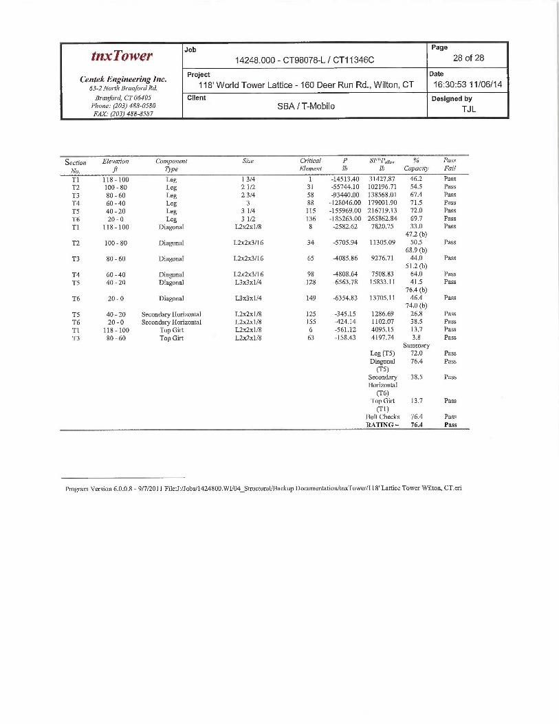
Job Page
tI~xTOW~r 14248.000 - CT98078-L / CT11346C 28 of 28
Centek Engineering Inc. Project Date
63-2 NorthBra~aforaxa. 118' Worid Tower Lattice - 160 Deer Run Rd., Wilton, C7 16:30:53 11/06/14
Branfo~~d, CT0640S Client Designed byPhone: (203) 488-0580 SBA / T-MOblle TJLFi1X.• (203) 488-8587
Section Elevation Compm~ent Size Critical P SF*Pogo,,. % ~' Pass
No. .~ Type Elemettt Ib Ib Capacity Fail
Tl 118 -100 Leg 1 3/4 1 -14513.40 31427.&7 46.2 PassT2 100 - 80 Leg 2 1/2 31 -55744.10 102196.71 54.5 Pass
T3 80-60 Leg 23/4 58 -93440.00 138568.01 67.4 Pass
T4 60 - 40 Leg 3 88 -128046.00 179001.90 71.5 Pass
TS 40 - 20 Leg 3 1/4 115 -155969.00 216719.13 72.0 Pass
T6 20 - 0 Leg 3 1/2 136 -185263.00 265862.84 69.7 Pass
Tl 118 -100 Diagonal L2ac2x1/8 8 -2582.62 7820.75 33.0 Pass47.2 (b)
T2 100 - 80 Diagonal L21c2x3/16 34 -5705:94 11305.09 50.5 Pass68.9 (b)
T3 80 - 60 Diagonal L2x2x3/l6 65 -4085.86 9276.71 44.0 Pass51.2 (b)
T4 60-40 Diagonal L2~1c3/16 98 -4808.64 7508.83 64.0 Pass
TS 40-20 Diagonal L3x3x1/4 128 -6563.78 15833.11 41.5 Pass76.4 (b)
T6 20 - 0 Diagonal L3x3x1/4 149 -6354.83 13705.11 46.4 Pass74.0 (b)
TS 40 - 20 Secondary Horizontal L2rc2x1 /8 125 -345.15 1286.69 26.8 Pass
T6 20 - 0 Secondary Horizontal L2~x1/8 155 -42414 1102.07 38.5 Pass
TI 118 -100 Top Gut L2~.x1/8 6 -561.12 4095.15 13.7 Pass
T3 80 - 60 Top Gut L2~cZx1/8 63 -158.43 4197.74 3.8 PassSummary
Leg (TS) 72.0 PassDiagonal 76.4 Pass(TS)
Secondary 38.5 PassHorizontal(T6)
Top Gut 13.7 Pass(T1)
Bolt Checks 76.4 PassRATING= 76.4 Pass
Program Version 6.0.0.8 - 9/7/2011 File:J:/Jobs/1424800.WU04 StructuralBackup Documentation/tmcTower/118' Lattice Tower Wilton, CT.eri
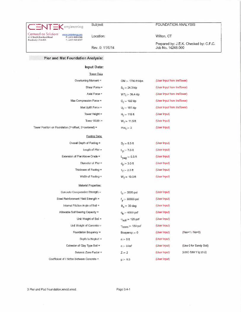
~~~~~~~,i~~ Subject:=~~=~Y
{~Gr~'~=reC~ .n ?r_i~utit~~i= ~ww~.a,~~;~,.,.:r;,,~~a~e~~~r~~,~r~ c~•,;.~~~.~c~~,r.~~ Location:Lkanirid,fT ik l4iS F.~ll~li a~:.4. ~al.y?
Rev. 0: 11 /6/14
Wilton, GT
Prepared by: J.E.K. Checked by: C.F.C.Job No. 14248.000
Pier and Mat Foundation Analysis:
Input Data:
Tower Data
Overturning Moment =
Shear Force =
Abal Force =
Max Compression Force =
Max Uplift Foroe =
Tower Height =
Tower Width =
Tower Position on Foundation (1=offset, 2=cerrtered) _
Footing Data:
Overall Depth of Footing =
Length of Pier =
E~Qension of PierAbove Grate =
Diameter of Pier =
Thickness of Footing =
Width of Footing =
Material Properties:
Concrete Compressive Strength =
Steel Reinforcment Yield Stren~h =
rrternal Friction Mgle of Soil =
Allavable Sal Bearing Capacity =
Unit Weight of Soil =
Unit Weight of Concrete =
Fourxlation Bouyancy =
Depth to Neglect =
Cohesion of Clay Type Soil =
Seismic Zone Factor =
Coefficient of Friction Between Concrete =
OM:= 1790•ft~kips
St = 24.3~kip
WTt:= 36.4•kip
Ct = 192~kip
Ut = 161•kip
Ht:= 118•ft
Wt:= 11.5•ft
Post := 2
Df = 8.5-ft
LP = 7.0•ft
LPa9:= 0.5•ft
dP:= 3.0•ft
Tf = 2.O~ft
Wf:= 19.0•ft
f~:= 3000•psi
fy ~ 60000• psi
~5:= 30•deg
qs = 6000-psf
7soil~ ~20•pcf
7conc~- 150•pcf
Bouyancy = 0
n=0~ft
c - 0• ksf
Z := 2
µ:= 0.5
(User Input from tnxTower)
(User Input from trucTower)
(User Input from tnxTower)
(User Input from tnxTower)
(User Input from tnxTower)
(User Input)
(Userinput)
(User Input)
(User Input)
(User Input)
(User Input)
(User Input)
(Userinput)
(User Input)
(Userinput)
(Userinput)
(Userinput)
(Userinput)
(Userinput)
(Userinput)
(Userinput)
(User Input)
(Userinput)
(User Input)
(User I nput)
(Yes=1 / N~0)
(Use 0 for Sandy Soll)
(UBG-1997 Fig 23-2)
3 Pier and Pad Foundation.xmcd.xmcd Page 3.4-1

Subject:~r ~ ter.
"f4fa7114tr7(11~}'
'Ct~f1R'tL`J ~Il ~e~CU~1~~5~3~?Hor11i6sanlaidRoasl v~ti~~ia~.~,wa Location:l4~nlrnd, l7 G41C15 F:~1611 a1~-L~S~1}
Rev. 0: 11 /6/14
Wilton, CT
Prepared by: J.E.K. Checked by: C.F.C.Job No. 14248.000
Pier Reinforcement:
Bar Size =
Bar Diameter =
Number of Bars =
Clear Cover of Reinforcement =
Reinforcement Location Factor=
Coating Factor =
Concrete Strength Factor =
Reinforcement Size Factor =
Pad Reinforcement:
Bar Size =
Bar Diameter =
Number of Bars =
Bar Size =
Bar Diameter =
Number of Bars =
Clear Cover of Reinforcement =
Reinforcement L,oration Factor =
Coating Factor =
Concrete Strength Factor =
Reinforcement Size Factor=
Calculated Factors:
Pier Reinforcement BarArea =
Pad Top Reinforcemerrt BarArea =
Pad Bottom Reinforcement BarArm =
Coefficient of Lateral Soil Pressure =
Load Factor =
ggPie~:= g (Userinput)
dbpier~- 1.O~in (Userinput)
NgP1ef;= ~g (Userinput)
CvrP1ef:= 3~in (Userinput)
aP1e~~ ~,p (Userinput) (AGI-200812.2.4)
pP1ef;= 1.0 (Userinput) (ACI-200812.2.4)
~`pier~— ~•~ (Userinput) (ACI-2008122.4)
7pier ~— ~ •~ (User I nput) (ACI-200812.2.4)
gStoP = 9 (User I nput) (Top of Pad)
dbtop ~ '~•"~z5•in (User Input) (Top of Pad)
NgtoP = 26 (User I nput) (fop of Pad)
Bsbot ~- 9 (User I nput) (Bottom of Pad)
dbbot ~ 1.125-in (User Input) (Bottom of Pad)
NBbot~— 26 (User Input) (Bottom of Pad)
GvrPad = 3.0•in (User Input)
°`pad — ~•~ (Userinput) (ACI-200812.2.4)
ppad~ ~•~ (Userinput) (ACI-200812.2.4)
~`pad~ ~•~ (Userinput) (ACI-200812.2.4)
7pad~- ~•~ (Userinput) (ACI-2008'12.2.4)
2
Abpier~ ~ d 4 ier _ 0.785•in2
2
Abtop :_ ~r d4 P = 0.994•in2
2
p`bbot ~_ ~ dbbot _ 0:994 in2
1 + sfr~~s) —KP. 1— si~~s — 3
LF := 1.333 if Ht < 700~ft = 1.333
1.7 if Ht >_ 1200•ft
Ht — 700ft1.333 + • 0.4 otherwise
1200ft — 700ft
3 Pier and Pad Foundation.xmcd.xmcd Page 3.4-2

Subject:
'Cerlter~d ~:n S~Culit~n~. ~.v~.»,n3-]Har~Mi&anfu~dFiarJ P: (?o],.~4Effiti`,~a Location:Nranlmd, L~T Bbitry} F.IlZ~tIi68~S47
Rev. 0: 11 /6/ 14
Wilton, CT
Prepared by: J.E.K. Checked by: C.F.C.Job No. 14248.000
Stability of Footing:
Adjusted Concrete Unit Weight =
Adjusted Soil Unit Weight =
ry~ := if(Bouyancy = 1, ryconc — 62.4pcf, ryconc~ = 150• pcf
rys := if(BouyancY = 1,'Ysoil — 62.4pcf,rysoil~ = 120•pcf
Passive Pressure =
Ultimate Shear =
Weight of Concrete =
Weight of ShcAbove Footing =
Weight of Soil Wedge at Back Face =
Tower Offset =
Total Weight =
Resisting Moment =
Overturning Moment =
Factor of SafetyAcW~ _
Factor of Safety Required =
PPS = KP rys n+ c2~~ = O ksf
PPt = KP 75 (Df — Tf) + c2~~ = 2.34~ksf
PtoP:= it[n < (Df — Tf), PPt, PPS] = 2.34 ksf
Pbot=- KP7S•Df+c•2•_~K =3.06~ksfv ~
Ptop+ PbotPave 2 = 2•~•ksf
TP = ii~n < ~~f —
Tf~'Tf' I~f — ~~~ —
2
AP = Wf~TP= 38
Su~ Pave'AP= 102.6•kip
WTI:= L(Wf2~Tf) +(3)~~dP4~LP~J•ry~= 130.566•kip
d Z ~r /WTS.~ := Wf2— l3)- P4 ~ll~ — ~Pa9 n J -rys —
265.04~kip
WTsz:= Ll~
—LPa~)2•tan(~5) W
fJ•ry5=27.808~kip
X rWf (Wt•cos(30•deg))1 X -_ Wf _ ~Wt•cos(30~deg))
t1 ~— ~ 2 — z ~ t2 2 3
Xt = if(Post~Xt1~X~) = 4.52
2f r(Wt-cos330~deg)~ 1Xoff=-- +Xt =1.66
WTtot:= WTI+ WTS~ = 395.6•kip
M :— (WT ) 2f + S • 3f + WT LW + ~ _ ~a3~~tan(~5)1 _
4390•kip~ftr — tot '— u s2' f
Mot = OM + St~(LP + Tf) = 2008.7 kip•ft
M~FS:=—=2.19
Mot
FS~~ := 2
OverTurning_Moment_Check := if(FS >_ FS feq, "Okay" , "No Goal" )
OverTurning_Moment_Check = "Okay"
3 Pier and Pad Foundation.xmcd.xmcd Page 3.4-3
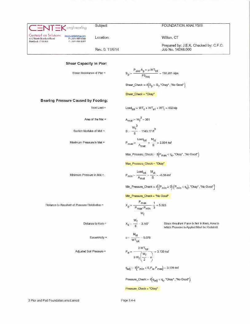
1 ~~ 1 ~ ~
~l~ft~~_fL'U P•il OtiJ~i4!1_`. .~e~tm,~com
o-]~7NnrU~&an~airJfw.rJ P'~;?i~bil~E~-[:~tx,1lSranlmd, LZ OG1[~5 F.~1C5 t1~~-gyN7
Location: Wilton, CT
Prepared by: J.E.K. Checked by: C.F.C.Rev. 0: 11/6/14 Job No. 14248.000
Shear Capacity in Pier:
Shear Resistance of Pier =
Bearing Pressure Caused by Footing:
Total Load =
Area of the Mat =
Section Modulus of Mat =
Ma~dm um Pressure in Mat =
Minimum Pressure in Mat =
Distance to Resultant of Pressure Distribution =
Distance to Kem =
Eccerdricity =
Adjusted Soil Pressure =
SP. Pave'AP+ µ•WTtot _ 150.201 •kips
FSreq
Shear Check = if(SP > St, "Okay" , "No Good" )
Shear Check = "Okay"
Loadtot:= WTI+ WTS~ + WTt = 432~kip
2Amat=- Wf = 361
3Wf 3
S := 6 = 1143.17•ft
Loadtot MotPm~:= + = 2.954~ksf
Amat S
Max Pressure_Check ~ if(P m~ < qs, "Okay" , "No Good" )
Max Pressure Check= "Okay"
Loadtot Mot
Amat S
Min_Pressure_Check = it[(Pmin ~ ~~'~Pmin < qs),"Okay","No Good"]
Min Pressure Check= "No Good"
Pmax 1XP:= — = 5.323
P,.,~~ P,„;,, 3
WXk:= 6f = 3.167 Since Resultant Force is Not in Kern, Area to
which Pressure is Applied Must be Raiuced.
Mote = = 5.078
WTtot
Z' WTtot
f3Wf~ z — e
gadj =- ~f~Pmin ~ 0, Pa,Pm~ = 3.139•ksf
Pressure_Check = ~f(gadj ~ 4s>Okay" , "No Good" )
Pressure_Check = "Okay"
3 Pier and Pad Foundation.xmcd.wncd Page 3.4-4
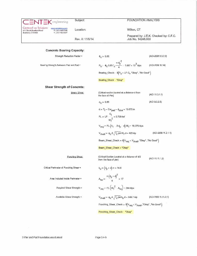
~,,~f ~~,~~~~~~r1~,~ Subject: FOUNDATION ANALYSIS~_I V~_'
L l`~rltct~`t~ hfl aL~kulit~ns gg~na-}rra~u~&~~ra~arw,.~ ~~,~,xi~c~~;;i~s Location: Wilton, CT14anfo~d,L'1ob~1U5 F:~:t~~u~db-K~F
Prepared by: J.E.K. Checked by: C.F.C.Rev. 0: 11/6/14 Job No. 14248.000
Concrete Bearing Capacity:
Strength Reduction Factor = ~~ = 0.65 (ACI-2008 9.3.2.2)
~r•d ZBearing Strength Between Pier and Pad = Pb:= ~~ 0.85•f~ P = 1.687 x 10³•kips (ACI-200810.14)
4
Bearing_Check = if(Pb> LF~Ct,"Okay","No Good")
Bearing_Check = "Okay"
Shear Strength of Concrete:
Beam Shear: (Critical section located at a distance d fromthe face of Pier) (ACI 11.31.1)
cy~ = 0.85 (ACI 9.3.2.5)
d = Tf - CvrPad - dbbot - 19.875 in
CtFL LF = 0.709•ksf
W 2f
V~~:= FL•(Xt-.5•dP-d)•Wf= 18.375•kips
VAvail ~- ~c'2' f~ psi•Wf•d= 422•kip (ACI-20D8 11.2.1.1)
Beam_Shear_Check := if(Vreq ~ VAvail ~ ~~Okay" , "No Good" )
Beam_Shear Check = "Okay"
Punching Sher. (Critical Section Located at a distance of d/2from the face of pier) (ACI 11.11.1.2)
Critical Perimeter of Punching Shear= bo:= (dP+ d)•~r = 14.6
~•!dP + d\Z
Area Included Inside Perimeter= qbo:= ~ 4 ~ = 17
Required Shear Strength= Vfeq = FL~(Wf2-Abo) =244~kips
Available Shear Strength = ugvail ~- ~c 4- f~ psi~bo d = 649.7~kip (ACI-2008 11.11.2.1)
Punching_Shear_Check:= if(Vreq ~ VAvail~~~Okay","No Good")
Punching_Shear_Check = "Okay"
3 Pier and Pad Foundation.xmcd:~cmcd Page 3.4-5
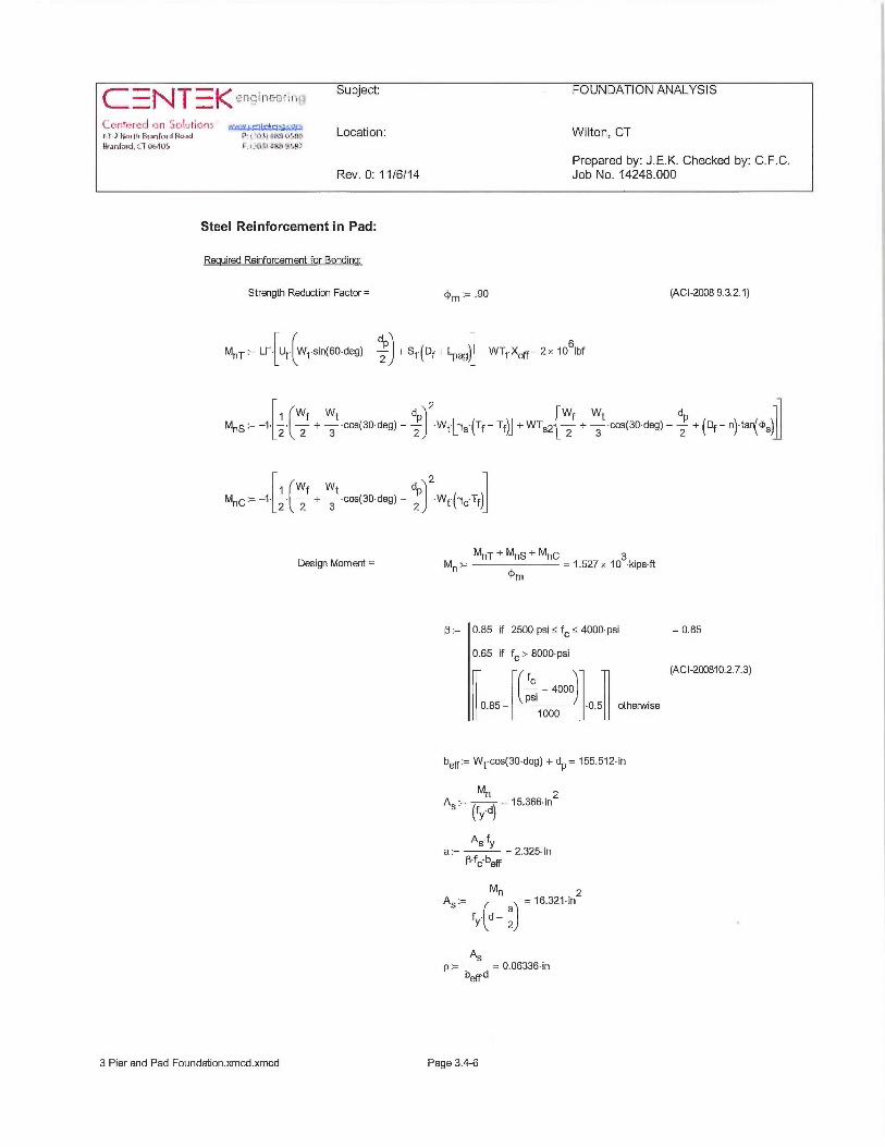
Subject: FOUNDAT1 '4
'C!z(if9_fLf~ ~fl ]6~4t~IG~tYr eww c,±ilr};q`,~,',}~'n~-rrrau~&~,ra~~rw~ ~,,.~~~,.~:~,;~c,~.,~~:• Location: Wilton, CT14~arsfwd.it~9f~5 r.:. ~... t.~d+>
Prepared by: J.E.K. Checked by: C.F.C.Rev. 0: 11/6/14 Job No. 14248.000
Steel Reinforcement in Pad:
Required Reinforcement for Bendinct:
Strength Reduction Factor = ~m :_ .90 (ACI-2008 9.3.2.1)
MST = LF-~Ut-~Wt~sin(60•deg) - 2pJ + St~(Df+ I~a9)~ - WTt'Xoff- 2 z 1061bf
2
MSS :_ -1•~.2•~ 2f + 3t ~cos(30•deg) - ZPJ Wt~[rys (Tf Tf)] + WTs2•L 2f + 3t~cas(30•deg) - 2 + (Df- n) ta.l~s~
d~ 21 rWf Wt 1 (
M~~ = -1~ 2~\ 2 + 3 •cos(30~de9) - 2 I ~Wt~lry~ Tf~J
Design Moment = Mn:= MnT + ~nS + MnC _ 1.527 x 10³•kipsft
m
p:= 0.85 if 2500-psi <_ f~ 5 4000~psi
0.65 if f~> 8000~psi
0.85-~~PS~-4000
J~-0.5~ otherwise1000
beff~- Wt'cos(30•deg)+dP= 155.512•in
AS•- Mn - 15.366•inz(fy d)
AS fya:= =2.325•in
a'fc bell
AS:= M~ = 16.321•in2a
fy d - 2
ASp = = 0.06336~in
beffd
= 0.85
(ACI-200810.2.7.3)
3 Pier and Pad Foundation.xmcd.xmcd Page 3.4-6

Subject: FOUNDATION ANALYSIS
'C~jnh=rc~l rn 5crulic~!is ~.~~,»,~~xrc.a-~Ha.u~&~rp~er~ ~..:o:~.~,ar;a{,=..,r:• Location: Wilton, CTI4~ntmd,tTiridtS ~ .. .. .
Prepared by: J.E.K. Checked by: C.F.C.Rev. 0: 11/6/14 Job No. 14248.000
Required Reinforcement fa Tem [~erature and Shrinkacte:
Psh - •0018 if fy >_ 60000 psi = 0.0018 (ACI -20087.12.2.1)
.0020 otherwise
Check Bottom Bars: ~ beff ~ 2As = i p? Psh,As,Psh~ 2 •d = 16.3~in
AsProv ~- Abbof NBb~ = 25.8• in2
Pad_Reinforcement_Bot := if(AsProv ~ As, "Okay" , "No Good" )
Pad_Reinforcement_Bot = "Okay"
Check too Bars:
bell ~ 2As = i p>- psh~As>Psh~ 2 -d = 16.3•in
AsProv~ Abtop'NBtop-25.8~in2
Pad_Reinforcement_Top = if(AsProv ~ As, "Okay" , "No Good"
Pad_Reinforcement_Top = "Okay"
Developement Length Pad Reinforcement:
Bar Spacing =
Spacing or Cover Dimension =
Transverse Reinforcement Index=
Minimum Developmerrt Length =
Available Length in Pad =
B - Wf- 2~CvrPad - NBbofdbbot = 7.71-insPad ~- NBbot- 1
BsPad BsPadc = i CvrPad < 2 , CvrPad, 2 = 3~in
~tr~- ~ (ACI-20D8 12.2.3)
3•fyaPad' ppad'rypad'apad~dbt ~- c + k ' dbbot - 34.7-in
tr40• f~•psi•
dbbot
~dbmin ~- 12•in (ACI-200812.2.1)
~dbtCheck~ ~f~~-dbt ~ ~dbmim~~Use L.dbY' ,"Usel.dbmin") _ "Use L.dbY'
Wf wtPad ~ Z - 2 - CvrPad = 42•in
Lpad_Check:= if(LPad ~ ~dbt ~ ~~Okay" , "No Good" )
Lpad_Check= "Okay"
3 Pier and Pad Foundation.xmcd:xmcd Page 3.4-7
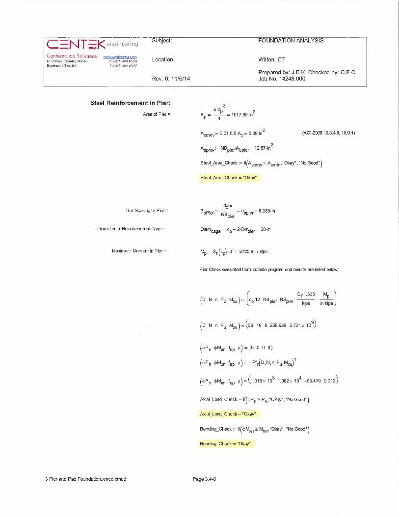
~ I'~1 ~ ~. ~~fN!~911G~f If~~~~ ~'1.
~L•.n'~_'PC~ :fl aC+pu~It7/71 ;gpmp~;{qg~bl-}Na,ui&a,ruidRa,+a ~:i;`C+}~k~i+SfHa14anlold, i-T QGiU4 F. ijC~tlip'4K~g7
U
Location: Wilton, CT
Prepared by: J.E.K. Checked by: C.F.C.Rev. 0: 11/6/14 Job No. 14248.000
Steel Reinforcement in Pier:
Area of Pier=
Bar Spacing In Pier =
Diameter of Reinforcemerrt Cage =
Ma~dmum Moment in Pier=
~~dP2 ZAP:= 4 = 1017.SS~in
Asmin~- 0.01.0.5•AP= 5.09~in2 (ACI-20Q810.8.4& 10.9.1)
Asprov~- NBpierAbpier- 12.57~in2
Steel_Area_Check := if(Asprov ~ Asmin • ~~Okay" , "No Good" )
Steel_Area_Check = "Okay"
dP ~r
BsPier~- NB — dbpier— 6.069~inpier
Diamcage~ dP-2•CvrP1ef=30•in
MP:= St~(LP)~LF = 2720.9 in~kips
Pier Check evaluated from outside program and results are listed below;
Ct~ 1.333 MP(D N n P~ MX~) :_ ~dP 12 NBPier BSpier kips in•kfps)
ID N n P~ Mx~) _ (36 16 8 255.936 2.721 x 10³)
(~P~ ~M~ fsP p):= (0 0 0 0)
(~P~ ~M~ fsP p):_ ~P'~(D N n P~ MX~IT
(~Pn ~M~ fsP p) _ (1.018 x 10³ 1.082 x 10⁴ —58.479 0.012)
Axial_Load_Check = if(Q~P~ >_ P~, "Okay" , "No Good" )
Axial_Load_Check = "Okay"
Bending_Check = if(c~M~ >_ MX~, "Okay" , "No Good" )
Bending_Check = "Okay"
3 Pier and Pad Foundation.xmcd.xmcd Page 3.4-8

~~~ i~'~,, ; , Subject: FOUNDATION ANALYSIS1 ~#
{.. t~nri'fLL) do $rSPuli~rG .,v~v~«~,khC~4~1:~3-1Ho~u~~~ro~er~ v:;~~,~ear;.~i~~ Location: Wilton, CTI~anfrnd~tl @tr1~15 F.il~yl.Elb:~-L~S4Y
Prepared by: J.E.K. Checked by: C.F.C.Rev. 0: 1116/14 Job No. 14248.000
Development Length Pier Reinforcement:
Available Length in Foundation:
pier ~ ~p — ~vrpier = 81 • in
pad := Tf — CvrPad = 21•in
Tension: (ACI-2008 12.2.3)
BsPier BsPierSpacing or Cover Dimension = c:= i CvrP1e~< ,CvrPier =din
2 2
Transverse Reinforcement = ktr;- p (ACI-2008 12.2.3)
3•fyaPier ppier 7pier'~`pier~dbt ~— ~ ~c+ kt~l ~dbpier= 27.39~in
40• f •psi•dbpier
Minimum Developmerrt Length =
Pier reinforcemerrt bars are standard 90 degree hooksand therefore developemerrt in the pad is computedas follows:
Compression:
1200•dbpierLdh :_ •.7 = 15.336~in (ACI 12.2.1)
f~
psi
~-db ~- m~~-dbt> ~-dbmin~ - 27.386•in
~-tension_Check ~— ~~~pier + pad ~ ~-dbt~~~Okay" , "No Good")
-tension Check - ~~Okay"
(ACI-200812.3.2)
.02~dbpierfy~dbc1~- = z1.909~in
f~ psi
.2
~dbmin ~ 0.0003 ~~b ~(dbpierfy) = 18•in
~dbc~ ~f~~dbc1'—~-dbmim~-dbc1~~dbmin~-21.909•in
~compression_Check ~— ~f~~-pier + pad ~ ~dbc~ ~~Okay" , "No Good" )
~compression_Check— ~~Okay"
3 Pier and Pad Foundation.xmcd.xmcd Page 3.4-9

~~~ ~fir~~ilivariripSubject: FOUNDATION ANALYSIS
Ce.nh-red ~n 5~~~ulic~ns ~~.~.~,~.,~~.~,narHo~~~&a,ra~er~ c~:~;~os~a~.~,~ Location: Wilton, CT -l4anlmd,L7~1[iS F.i1~tld~ay~RS_97
Prepared by: J.E.K. Checked by: C.F.C.Rev. 0: 11/6/14 Job No. 14248.000
Tie Size and Spacing in Column:
Minimum TeSize=
Seismic Factor=
Maximum Spacing=
Number of Ties Raauired =
Check Anchor Steel Embedment:
Depth Available =
Length ofAnchor Bolt =
T~~min = if(BSPier ~ 10, 3,4) = 3
Used #4 Ties
Siim1 ~= 16•dbpierz= 16•in
48•dTieSIim2 :_ $ z = 24~ in
SIim3 := Df~z = 102•in
SIim4 := 18in
(AG-2008 21.10.5)
SIim1
SIim2st1e:= min = 16•in
SIim3
SIim4
pier— 3~in
tie ~- + 1 = 5.875Stie
Dab := Lst —ABP = 5.83~ft
(0.11~fya)•in
~anchor~ = 12.55~ftf~ psi
Depth_Check = if(Dab ~ ~-anchor' ~~Okay" , "No Good" )
Depth_Check = "No Good"
Note: OK, Anchor plate is provtied
3 Pier and Pad Foundation.xmcd.xmcd Page 3.4-10

i = f' h €— , i, I ~ ~ ~ ~,.
~;;
The Antenna-Integrated Radio (AIR) is a single
tower-mounted unit that can replace the
antennas and radio for one sector. Additional
electronics such as ASC? and a RET Actuator
and control are also included. A passive
antenna function for an extra band is optional.
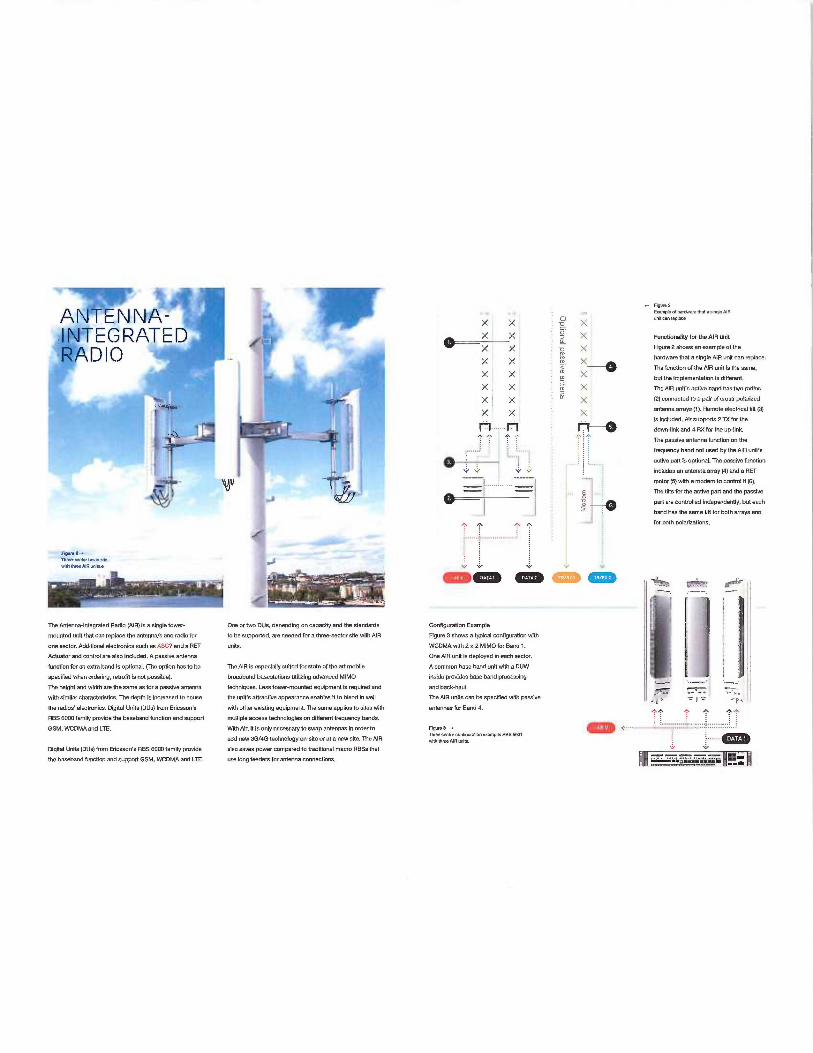
,~r~T~r~r~~-II~T~G~'aT~n
h~~/ \~I~
.~~
1t
t~\~ V
,r
~~z,mree-x~.r«iw,..~awiN Nree Nfl urvlse
'A I.
The Mtenna-Integrated Radio (AIR) is a single tower-
mounted untt that can replace the antannaJs and radio far
one sector. Additional ¢lecironics such as ASC? and a REf
Actuator and control are also included. A passive antenna
function for an ezira band is optional. (iha option has to ba
specified vfian ordering, retrafrt is nab possible).
Tha height and width are the same as for a passive antenna
with similar charactertstics. The depth Is increasetl to house
the radios' electronics. Digital Units (DUs) from Ericsson's
RBS 6000 family provide the 6asehand tunciion end support
GSM, WCDMA and LTE.
Digkal Units (DUsj from Ericsson's RBS fi000 family provide
the 6aseband function and support GSM, WCDMA antl L7E.
E ms- - . _' _~~: f
One or two DUs, depending on capecNy and the standards
to be supported, are needed for athree-sector site with AIR
units.
The AIR is especialty suited tar state of the art mohile
broadband basestatlons alit@Ing advanced MIMO
techniques. Less tower-mounted equipment is required and
the uNPs attractive appearance enahies N to blend in well
with other existing equipment. Tha same applies 10 sites with
multiple access technologies on different frequency bends.
With Air, tt is only necessary to swap antennas in orderfo
add new 3G/4G technology on-stte or at a new site. The AIR
also saves power compared to traditional macro RBSs that
use long feeders far antenna connections.
.- Fevre zs.w~demnyaw~uoc a:myb nw
X X -o X ~m~~~epw~
~x ~. ~ X Functionality far the AlR UMt
— ~( X -o ~( Fgure 2 shows an example of the
m hardware fiat a single AIR unit can replace.X x N X~~ The Tunctlon oitha AIR unit is the same,
X X ? X but the implementation is different.
X X m X The AIR unR's active band has two radios
X I X~ W x (2)connected to apair ofcross-polarized
X X X antenna arrays (7). Remote eleciriwl tilt (3)
~1 ~~~j is Included. Air supports 2170 for the
1 '~f - ~ -~ 1;) ~ tlown-link and 4RX for the up-link.
The passive antenna function on iha
.......: ~......: : ; ~ frequ cy 6and net used by the AlR uniPs
[ ac i n s ve unc ionfive part"s opiio al Thepas t i t'
v v inclutles an antenna artay (4) antl a RET~e~
- ~ ~~ ~ motor (5) with a madam to control
~<<ssrve
W W
_... ~ The tills for the active part and the pa '
J ~ part are controlletl indepandentty, but each
~~ 6and has the same 1(It for both arrays and
for both polarizations.
`V V V
~t ~.
i
Configuration Example t
figure 3 shows a typical configuration wish
WCDMA with 2 z? MIMO for Band 1.
One AIR unit is daployetl in each sac[a. -
A common base band unk wNh a OUW
inside provides hose band processing j
and back-haul. ~, ~;_-, ~~
The AIP units can be spedfied with passive
antennas for Band 4. ~ ^ ~
F~rcB ~ ~ ...........:...____.._________.........................:
mree senor cormg~rawne.ampr. was ssoiwith Nrea PlN urvK :.......
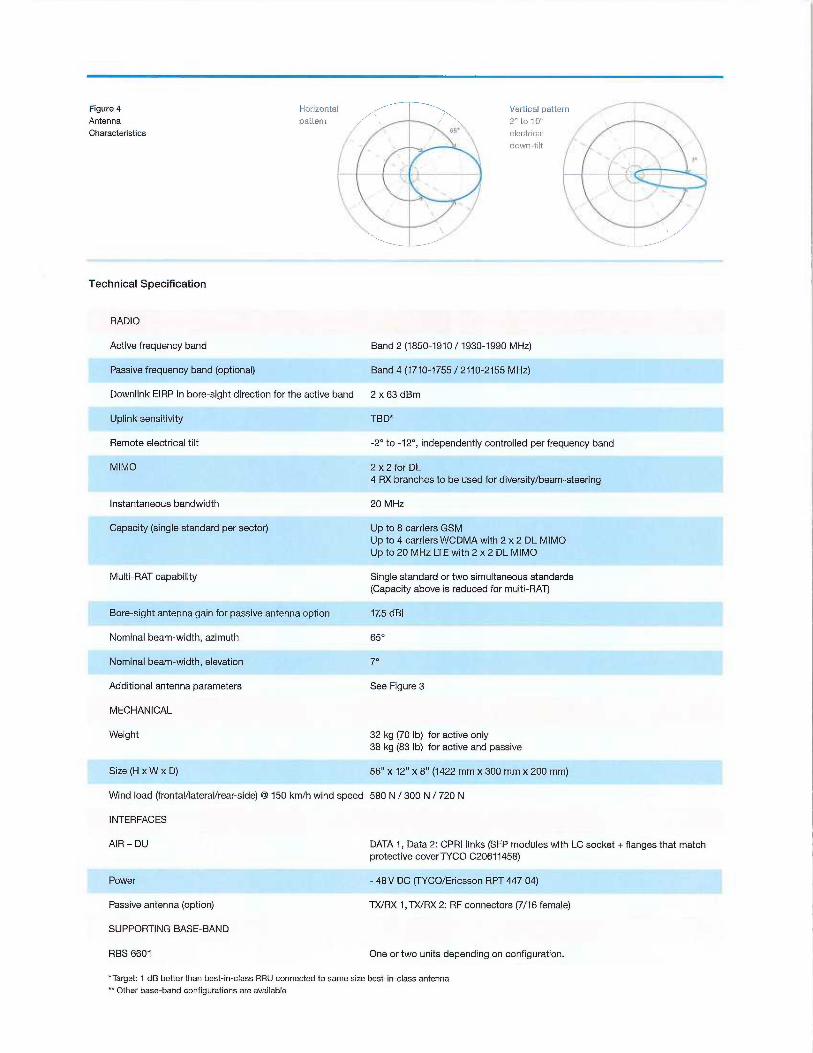
Figure 4AntennaCharacteristics
Technical Specification
Horizontapattern
Vertical patter2" to 1 D"electricaldown-tilt
RADIO
Active frequency band Band 2 (1850-1910 / 7930-1990 MHz)
Passive frequency band (optional) Band 4 (1710-1755 / 2710-2155 MHz)
Downlink EIRP in bore-sight direction for the active band 2 x 63 dBm
Uplink sensitivity
Remote electrical tilt
MIMO
Instantaneous bandwidth
Capacity (single standard per sector)
Multi-RAT capability
Bore-sight antenna gain for passive antenna option
Nominal beam-width, azimuth
Nominal beam-width, elevation
Additional antenna parameters
MECHANICAL
TBD`
-2° to -12°, independently controlled per frequency band
2x2forDL4 RX branches to be used for diversity/beam-steering
20 MHz
Up to 8 carriers GSMUp to 4 carriers WCDMA with 2 x 2 DL MIMOUp to 20 MHz LTE with 2 x 2 DL MIMO
Single standard or two simultaneous standards(Capacity above is reduced for multi-RATj
17.5 dBi
65°
7°
See Figure 3
Weight 32 kg (70 Ib) for active only38 kg (83 Ib) for active and passive
Size (H x W x D) 56" x 12" x 8" (1422 mm x 300 mm x 200 mm)
Wind load (frontal/lateral/rear-side) C~ 750 km/h wind speed 580 N / 300 N / 720 N
INTERFACES
AIR — DU DATA 1, Data 2: CPRI links (SFP modules with LC socket +flanges that matchprotective coverTYCO 020611458)
Power - 48 V DC (TYCO/Ericsson RPT 447 04)
Passive antenna (option) TX/RX 1,TX/RX 2: RF connectors (7/16 female)
SUPPORTING BASE-BAND
RBS 6601 One or two units depending on configuration.
'Target: 1 dB better than best-in-class RRU connected to same size best-in-class antenna** Other base-band configurations are available

DOUBLE TMA 17/21, PREMIUM
3GPP/AISG compatible with RET interface
~~
Improving a radio uplink by using tower mountedamplifiers is perceived as a key method of optimiz-ing radio networks. By ensuring maximum coverageincluding in-door penetration, a TMA supports thedesign of cost-efficient networks and extended talk-time handsets, low dropped call rates and high trafficbilling.
TMA designThis Double Premium TMA for 17/2100 MHz has 12dBgain and is 3GPP/AISG 2.0 compatible, with a RETinterface. It has superior RF performance, small sizeand low weight. There is a corresponding TMA ver-sion called ASC that has a higher gain and a VSWRmeasuring coupler.
System integrationThe Double TMA 17/2100 is a part of Ericsson's TMAfamily. Power, control and supervision are provided bythe RBS 3000. If sold to other RBS brand installations,
. j i.
~~io~'pr r y~"~~ ~Q~`"
:~'~
~tio- i
`~ .r
it can be controlled and supervised from the "AntennaSystem & TMA Control Module", AST-CM, via the RFfeeder.
3GPP/AISGTMA communication is based on the 3GPP/AISG protocolstandard and has a RET port for controlling antenna RETunits. The communication port allows multiple RETs orAntenna Line Devices to be supervised and controlled viathe TMA.
Future-proofThe Double TMA 17/21 Premium is designed for co-exis-tence with future complementary, mast-mounted devices.
F~ccellent reliabilityAs the world's largest supplier of TMAs, Ericsson has awell-proven track record of reliable TMA designs. Reliabil-ity enhancing features include dual LNAs, weatherproofdesign, integrated alarm and lightning protection.
E RICSSON

Features• Specified and verified as an integrated system
solution for Ericsson RBSs
• Possible to power both TMAs from one feede , or fromboth feeders
• High power capacity
• Automatic LNA by-pass function
• Built in lightning protection
• Excellent RF performance
• Connectors "in line"
• Distance between connectors simplifies sealing work
• A range of accessories for flexible site configurations
5 c~~~.
O~
r'
~9~''''n~,~~
Ie6 mm (3.4 in)
Product nameDouble TMA 17/21, Premium3GPP/ASIG compatible with RET interface
Radio performanceBandwidth:Receiving pass band:Transmitting pass band:RX Gain:Input IP3:IM3 at antenna port (2x43dBM):Noise figure midband:TX max input power (Max Peak):TX insertion loss:RX return loss:TX return loss:
Electrical specificationsInput power:Power consumption:
Mechanical specificationsDimensions (W x H x D):Weight:RF connectors:Ground connectors:DC/Alarm:Mounting:RET connectors:
Environmental specificationsTemperature range, full performance:MTBF:Sealing:Lightning protection:Safety approval:
Safety standard:
Product numberKRY 112 144/1
45 MHz1710 - 1755 MHz2110 - 2155 MHz12t 1 d616 dBm"-128 dBm1.0 d B*57 dBm0.25 dB*22 dB`22 dB'
+12 - 32 VDC< 4.5 W
155x176x71mm5 kg7-16 DIN femaleM8Superimposed on the RF signalPole or wall mountingDin con. IEC 60130-9 - Ed. 3.0 female
-40°C - +55°C80 yearsIP67IEC 62305-1, IEC 61000-6International: CB certified, IEC 60 529Europe: EN 60 529North America: NRTL, NEMA 3RUL 60950-1, IEC 60950-1
"Typical values
Ericsson AB 36/287 01 - FGC 101 764, rev Awww.ericsson.com O Ericsson AB, 2008
U
O
O
3
UO
Na

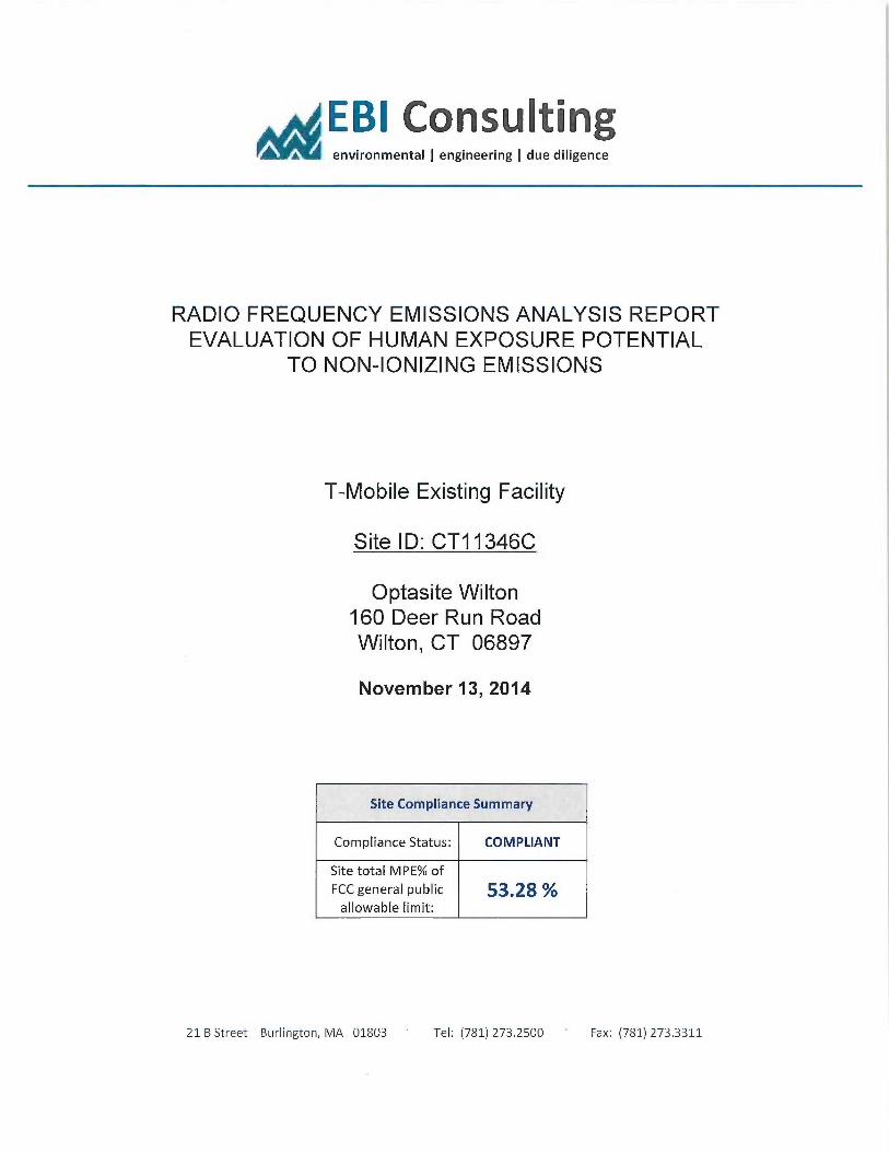
E61 Consulting~ environmental ~ engineering ~ due diligence
RADIO FREQUENCY EMISSIONS ANALYSIS REPORTEVALUATION OF HUMAN EXPOSURE POTENTIAL
TO NON-IONIZING EMISSIONS
T-Mobile Existing Facility
Site ID: CT11346C
Optasite Wilton160 Deer Run RoadWilton, CT 06897
November 13, 2014
Site Compliance Summary
Compliance Status: COMPLIANT
Site total MPE% ofFCC general public 53.2$ ~oallowable limit:
21 B Street Burlington, MA 01803 Tel: (781) 273.2500 Fax: (781) 273.3311

EBI Consul~na environmental ~ engineering ~ due diligence
November 13, 2014
T-Mobile USAAttn: Jason Overbey, RF Manager35 Griffin Road SouthBloomfield, CT 06002
Emissions Analysis for Site: CT11346C — Optasite Wilton
EBI Consulting was directed to analyze the proposed T-Mobile facility located at 160 Deer Run Road,
Wilton, CT, for the purpose of determining whether the emissions from the Proposed T-Mobile Antenna
Installation located on this property are within specified federal limits.
All information used in this report was analyzed as a percentage of current Maximum Permissible
Exposure (% MPE) as listed in the FCC OET Bulletin 65 Edition 97-Oland ANSUIEEE Std C95.1. The
FCC regulates Maacimum Permissible Exposure in units of microwatts per square centimeter (µW/cm2).
The number of µW/cm2 calculated at each sample point is called the power density. The exposure limit.
for power density varies depending upon the frequencies being utilized. Wireless Carriers and Paging
Services use different frequency bands each with different exposure limits, therefore it is necessary to
report results and limits in terms of percent MPE rather than power density.
All results were compared to the FCC (Federal Communications Commission) radio frequency exposure
rules, 47 CFR 1.1307(b)(1) — (b)(3), to determine compliance with the Maximum Permissible Exposure
(Ml'E) limits for General Population/LTncontrolled environments as defined below.
General population/uncontrolled exposure limits apply to situations in which the general public maybe
exposed or in which persons who are exposed as a consequence of their employment may not be made
fully aware of the potential for exposure or cannot exercise control over their exposure. Therefare,
members of the general public would always be considered under this category when exposure is not
employment related, for example, in the case of a telecommunications tower that exposes persons in a
nearby residential area.
Public exposure to radio frequencies is regulated and enforced in units of microwatts per square
centimeter (µW/cmz). The general population exposure limit for both the PCS and AWS bands is 1000
µW/tine. Because each carrier will be using different frequency bands, and each frequency band has
different exposure limits, it is necessary to report percent of MPE rather than power density.
21 B Street ~ Burlington, MA 01803 Tel: (781) 273.2500 Fax: (781) 273.3311
EBI Cons~oc~ environmental ~ engineering ~ due diligence
Occu~ationaUcontrolled exposure limits apply to situations in which persons are exposed as a
consequence of their employment and in which those persons who are exposed have been made fu11y
awaxe of the potential for exposure and can exercise control over their exposure. OccupationaUcontrolled
exposure limits also apply where exposure is of a transient nature as a result of incidental passage through
a location where exposure levels may be above general population/uncontrolled limits (see below), as
long as the exposed person has been made fully aware of the potential for exposure and can exercise
control over his or her exposure by leaving the area ar by some other appropriate means.
Additional details can be found in FCC OET 65.
CALCULATIONS
Calculations were done for the proposed T-Mobile Wireless antenna facility located at 160 Deer Run
Road, Wilton, CT, using the equipment information listed below. All calculations were performed per
the specifications under FCC OET 65. Since T-Mobile is proposing highly focused directional panel
antennas, which project most of the emitted energy out toward the horizon, all calculations were
performed assuming a lobe representing the maximum gain of the antenna per the antenna manufactures
supplied specifications, minus 10 dB, was focused at the base of the tower. For this report the sample
point is the top of a 6 foot person standing at the base of the tower.
For all calculations, all equipment was calculated using the following assumptions:
1) 2 GSM channels (PCS Band - 1900 MHz) were considered for each sector of the proposed
installation. These Channels have a transmit power of 30 Watts per Channel
2) 2 UMTS channels (AWS Band — 2100 MHz) were considered for each sector of the. proposed
installation. These Channels have a transmit. power of 30 Watts per Channel.
3) 2 LTE channels (AWS Band — 2100 MHz) were considered for each sector of the proposed
installation. These Channels have a transmit power of 60 Watts per Channel.
4) All radios at the proposed installation were considered to be running at full power and were
uncombined in their RF transmissions paths per carrier prescribed configuration. Per FCG
OET Bulletin No. 65 -Edition 97-01 recommendations to achieve the maximum anticipated
value at each sample point, all power levels emitting from the proposed antenna installation
are increased by a factor of 2.56 to account for possible in-phase reflections from the
surrounding environment. This is rarely the case, and if so, is never continuous.
21 B Street 'Burlington, MA 01803 Tel: (781) 273.2500 Fax: (781) 273.3311
EBI Consul~oc~, environmental ~ engineering ~ due diligence
5) For the following calculations the sample point was the top of a six foot person standing at
the base of the tower. The maximum gain of the antenna per the antenna manufactures
supplied specifications minus 10 dB was used in this direction. This. value is a very
conservative estimate as gain reductions for these particular antennas are typically much
higher in this direction.
6) The antennas used in this modeling are the Ericsson AIR21 B4A/B2P for 1900 MHz (PC5)
and 2100 MHz (AWS) channels.. This is based on feedback from the carrier with regards to
anticipated antenna selection. The Ericsson AIR21 S4A/B2P has a maximum gain of 15.9
dBd at its main lobe. The maximum gain of the antenna per the antenna manufactures
supplied specifications, minus 10 dB, was used for all calculations. This value is a very
conservative estimate as gain reductions for these particular antennas are typically much
higher in this direction.
7) The antenna mounting height centerline of the proposed antennas is 118 feet above ground
level (AGL).
8) Emissions values for additional carriers were taken from the Connecticut Siting Council
active database. Values in this database are provided by the individual carriers themselves.
All calculations were done with respect to uncontrolled /general public threshold limits.
21 B Street 'Burlington, MA 01803 Tel: (781) 273.2500 Fax: (781) 273.3311

E61 Consultinenvironmental ~ engineering ~ due diligence
T-Mobile Site Inventory and Power Data
Sector: A Sector: B Sectoz: CAntenna #: 1 Antenna #: 1 Antenna #: 1
Ericsson AIR21 Ericsson AIR21 Ericsson AIR21Make /Model:
B4ABZP Make /Model: B4~~P Make /Model:
B4A/B2PGain: 15.9 dBd Crain 15.9 dBd Gain: 15.9 dBd
Hei lit AGL): 118 Hei ht AGL : 118 Hei ht (AGL : 118
Frequency Sands 1900 MF3z(PCS) /
Frequency Bands 1900 MHz(PCS) /
Frequency Bands 1900 MIIz(PCS) /
2100 MHz AWS) 2100 MHz (AWS 2100 MAz AW5Channel Conut 2 Channel Count 2 # PCS Channels: 2
Total TX Power: 120 Total TX Power: 120 # AWS Channels: 120ERP 1,906.06 ERP 1,906.06 ERP 1,906.06
AntennaAl MPE% 1.34 AntennaBl MPE% 1.34 Antenna Cl MPE% 1.34
Antenna #: 2 Antenna #: 2 Antenna #: 2Ericsson AIR21 Ericsson AIR21 Ericsson AIR21
Make /Model: B4A/BZp
Make /Model: B4A/BZP
Make /Model: B4AB2P
Gain: 15.9 dBd Gain: 15.9 dBd Gain: 15.9 dBdHeia t(AGL : 118 Hei ht AGL): 118 Hei t AGL): 118
Frequency Bands 1900 MI3z(PCS) /
Frequency Bands 1900 MHz(PCS) /
Frequency Bands 1900 MHz(PCS) /
2100 MHz AWS 2100 MHz AWS 2100 MI~z AWS
Channel Count 4 Channel Count 4 Channel Count 4Total T'X Power: 120 Total TX Power. 120 Total T'X Power: 120
ERP 1,906.06 ERP 1,906.06 ERP 1,906.06
Antenna A2 MPE% 1.34 Antenna B2 MPE% 1.34 Antenna C2 MPE% 134
Slte COm osite MPE% T-Mobile Sector 1 Total: 2.68
Carrier MPE% T-Mobile Sector 2 Total: 2.68 °/a
T-Mobile 8.03 T-Mobile Sector 3 Total: 2.68
AT&T 19.83 % Site Total: 53.28
Verizon Wireless 25.42
Site Total MPE %: 53.28
21 B Street 'Burlington, MA 01803 Tel: (781) 273.2500 Fax: (781) 273.3311

EBI Cons~~~~o~~ environmental ~ engineering ~ due diligence
Summary
All calculations performed for this analysis yielded results that were within the allowable limits for
general public exposure to RF Emissions.
The anticipated maa~imum composite contributions from the T-Mobile facility as well as the site
composite emissions value with regards to compliance with FCC's allowable limits for general public
exposure to RF Emissions are shown here:
T-Mobile Sector Power Densi Value (%Sector 1: 2.68Sector 2: 2.68Sector 3 : 2.68
T-Mobile Total: 8.03
Site Total: 53.28
Site Com Hance Status: COMPLIANT
The anticipated composite MPE value for this site assuming all carriers present is 53.28% of the
allowable FCC established general public limit sampled at the ground level. This is based upon values
listed in the Connecticut Siting Council database for e~sting carrier emissions.
FCC guidelines state that if a site is found to be out of compliance (over allowable thresholds), that
carriers over a 5% contribution to the composite value will require measures to bring the site into
compliance. For this facility, the composite values calculated were well within the allowable 100%
threshold standard per the federal government.
Scott Heffernan
RF Engineering Director
EBI Consulting
21 B Street
Burlington, MA 01$03
21 B Street 'Burlington, MA 01803 ~ Tel: (781) 273.2500 Fax: (781) 273.3311