Embed Size (px)
Citation preview

GOHFNWOLF_P~._ATTORNEYS AT LAW
August 29, 2014
Attorney Melanie BachmanActing Executive DirectorConnecticut Siting CouncilTen Franklin SquareNew Britain, CT 06501
RACHEL A. SCHWARTZMAN
Please Reply To: BridgeportWriter s Direct Dial: (203) 337-4110E-Mail: rschwartzmanQcohenandwolf.com
Re: Notice of Exempt ModificationFred Callahan/T-Mobile co-locationT-Mobile Site ID CT11174A99 Cedarwood Lane, Newington, CT (aka 2111 Berlin Turnpike, Newington, CT)
Dear Attorney Bachman:
This office represents T-Mobile Northeast LLC ("T-Mobile") and has been retained to fileexempt modification filings with the Connecticut Siting Council on its behalf.
In this case, Fred Callahan owns the existing guyed lattice telecommunications towerand related facility at 99 Cedarwood Lane Newington, CT (aka 2111 Berlin Turnpike,Newington, CT) (-72.70856/41.69428). T-Mobile intends to replace 3 existing antennas with 3new antennas and related equipment at this existing telecommunications facility in Newington("Newington Facility"). Please accept this letter as notification, pursuant to R.C.S.A. X16-50j-73,of construction which constitutes an exempt modification pursuant to R.C.S.A. ~ 16-50j-72(b)(2).In accordance with R. C.S.A. ~ 16-50j-73, a copy of this letter is being sent to the Mayor StephenWoolds, and the property owner, the Callahan Qualified Personal Residence.
The existing Newington Facility consists of a 170-foot guyed lattice tower.l T-Mobileplans to replace 3 existing panel antennas with 3 new panel antennas at a centerline of 163 feet.(See the plans revised to August 5, 2014 attached hereto as Exhibit A). T-Mobile will also installcoax cables routed with existing coax cables, install radio remote units mounted on H-framesattached to an existing ice bridge post, and install bias tees. The existing Newington Facility isstructurally capable of supporting T-Mobile's proposed modifications, as indicated in thestructural analysis dated August 22, 2014, and attached hereto as Exhibit B.
1 While the online docket for the Connecticut Siting Council does not provide a docket or petition numberfor approval of this structure, it does reference this structure in connection with a notice of intentcaptioned EM-NEXTEL-094-060407, EM-POCKET-094-080917, EM-T-MOBILE-094-090113, and EM-CLEARWIRE-094-100311.
IL15 BROAD STREET ISH DEER HILL AVENUE 3ZO POST ROAD WEST C>S~ ORANGE CANTER ROAD
P.O. Box 1821 DANBURY, CT O6H1O WESTPORT, CT OEHHO OAANGB, CT OCX~J~
BRIDGEPORT, CI' 06601-1821 Tic: (203) 7922771 Z~r.: (203) 222-1034 'I~[.: (203) 298 066'I~►.: (203) 368-0211 Fnx: (203) 791-8149 Fpac: (203) 227-1373 Fix: (203) 298-0068Fnac: (203) 3949901

COHFNWOLF~P.C.~ATTORNEYS AT LAW
August 29, 2014CT11174APage 2
The planned modifications to the Newington Facility fall squarely within those activities
explicitly provided for in R.C.S.A. g 16-50j-72(b)(2).
1 . The proposed modification will not increase the height of the tower. T-Mobile's
existing antennas are at a centerline of 163 feet; the replacement antennas will be installed at the
same 163 foot level. The enclosed tower drawing confirms that the proposed modification will
not increase the height of the tower.
2 . The proposed modifications will not require an extension on the site boundaries
or lease area, as depicted on Sheet 1 of Exhibit A. T-Mobile's equipment will be located entirely
within the existing compound area.
3 . The proposed modification to the Facility will not increase the noise levels at the
existing facility by six decibels or more.
4 . The operation of the replacement antennas will not increase the total radio
frequency (RF) power density, measured at the base of the tower, to a level at or above the
applicable standard. According to a Radio Frequency Emissions Analysis Report prepared by
EBI dated August 28, 2014. T-Mobile's operations would add 5.29% of the FCC Standard.
Therefore, the calculated "worst case' power density for the planned combined operation at the
site including all of the proposed antennas would be 88.39% of the FCC Standard as calculated
for a mixed frequency site as evidenced by the engineering exhibit attached hereto as Exhibit C.
For the foregoing reasons, T-Mobile respectfully submits that the proposed replacement
antennas and equipment at the Newington Facility constitutes an exempt modification under
R.C.S.A. § 16-50j-72(b)(2). Upon acknowledgement of this exempt modification, T-Mobile shall
commence construction approxunately sixty days from the receipt of the Council's decision.
Sinc rely,
_~ ~l~/~~__ v v~
Rachel A. Schwartzman, Esq.
cc: Mayor Stephen Woods, Town of Newington
Fred CallahanThe Callahan Qualified Personal ResidenceJamie Ford, EBI Consulting

PROPOSED (6) T—MOBILECOAX CABLE ROUTED WITH
EXISTING COAX CABLES
EXISTING X c~ JS~P6~
Fir T—MOBILE 170' t x~x~ PtiS ~1 sE ~~~~-t,~,°R GUYED TOWER x~x~ "
rti ~9y ~ ` EXISTING`~~o"t's x' * T—MOBILE
x~'~~' CONCRETE PAD
x'X~X~x~X~X'X' \ xK
1 PROPOSED T—MOBILE
~ ~ ON PROPOSED NTED
" x H—FRAME ATTACHED% TO EXISTING ICE
E AT&T G 1 BRIDGE POST
1 EQUIMPENT ~ 1SHELTER x EXISTING T—MOBILE
1 H—FRAME TO REMAINx
1 1
1 EXISTING 1NEkTEL
1 CESBR DGE ABOVE1 EQUIMPENTSHELTER
xx
EXISTINGx ~o EQUIMPEN t EXISTING CHAIN
mN SHELTER, 1 LINK FENCEU ~ BY x
1 EXISTING ~Q OTHERS
EXISTING TRANSFORMER CONCRETE xPAD 1
x
1 EXISTING GENERATOR1 x1
EXISTING METER BANK 'x'X~X~x~xJ
~X~x
~ ~x~x X''~
~X~.x
x~x~x"~
CONFIGURATION
7 0 4 B U APPROX. NORTH
NOTE:ALL EQUIPMENT LOCATIONS ARE I /~APPROXIMATE AND ARE SUBJECT TO SITE P lJ"~N SCALE: 1/16" = 1'-0"APPROVAL BY LESSEE/LICENSEESTRUCTURAL AND RF ENGINEERS.
PREPARED BY: CLIEM: SfTE INFO: SUBMfTTALS DRAWN BY: SHEET N0:
~EBI Consultin CT11174A N0. DATE DESCRIPTION gy SH
T—M01711E NOT'tl'leaSt, LLC q OB OS 14 FOR REVIEW SH CHECKED BY:.~x~om.m.~l•~o~~~n~cia~. ana~~~ CALLAHAN ~ ~
21 B Street ~ eudingWn, MA oteo3 35 GRIFFIN ROAD SOUTH P~ LE 1Tel: (787J 273-2500~Fax: (781)2733311 BLOOMFlELD, CT 06002 TOWER_1
w~w,.ebimnsulting.~nm Bfi0.692.7100 pA~99 CEDARWOOD LANE (BERLIN TPKE)
EBI JOB NO.: 81740795 NEWINGTON. CT, 06111 07/26/14

EXISTING T—MOBILECONCRETE EQUIPMENT SLAB
EXISTING T—MOBILE ICEBRIDGE NOT SHOWN FOR
CLEARIlY
EXISTING T—MOBILE 3106CABINET. TO REMAIN
EXISTING T—MOBILE 58000CABWEf. TO REMAIN
EXISTING T—MOBILE SBOOCCABINET, TO REMAIN
EXISTING T—MOBILETELCO BOk
EXISTING T—MOBILEPOWER BREAKER
EXISTING T—MOBILE H—FRAME
EXISTINGT—MOBILECONCRETE PAD
EXISTINGT—MOBILE ICEBRIDGE &COAXSUPPORT FRAME N
0
0
PROPOSEDT—MOBILE(3} RRUS
PROPOSEDT—MOBILE H—FRAMEATTACHED TOEXISTING ICEBRIDGE POST
PROPOSED T—MOBILE03" POST
EXISTINGT—MOBILE ICEBRIDGE POST &COAX SUPPORTFRAME
CONFIGURATION
7 0 4 B U APPROX. NORTH
NOTE:ALL EQUIPMENT LOCATIONS AREAPPROXIMATE AND ARE SUBJECT TO EQUIPMENT PLAN SCALE: 1 /4" = 1'-0"APPROVAL BY LESSEE/LICENSEESTRUCTURAL AND RF ENGINEERS.
PREPARED BY: CLIENT: SfTE INFO: SUBIAfITALS DRAWN BY: SHEEP NO:
~EBI Consultin CT11174A N0. DATE DESCRIPTION ~, SH
g T-Mobile Northeast, LLC p 08/05/14 FOR REVIEW SH CHECKED BY:.~Y~,m~ ~.~a~~K~~a~d~.~~~e.~w CALLAHAN ^/21 8 Slreat ~ Burlington, MA 01803 35 GRIFFIN ROAD SOUTH
P~ LE~LTel: (781J 2732500~Fax: X781)2733377 B~OOMFIELD, CT 06002 TOWER_1vxia.ehimnsuWng.com 86.892.7100 pA~:
99 CEDARWOOD LANE (BERLIN TPKE)
EBI JOB NO.: 81740795 NEWINGTON. CT, 06111 07/28/14
y _0"

EXISTING
T—MOBILE 170' t
GUYED TOWER
sF92~y oR
~y3~i'off
EXISTING PIPE
MAST (NP.)
PROPOSEDT—MOBILE SMARTBIAS T (NP. OF1 PER ANTENNA,
TOTAL OF 3)
PROPOSEDT—MOBILE PANEL
ANTENNAS TO SWAPEXISTING PANNEL
ANTENNA (NP.' OF1 PER SECTOR,
TOTAL OF 3)
PROPOSED COMBINEDEXISTING T—MOBILE PANELANTENNAS ON DUAL POLE(NP. OF 1 PER SECTOR,
TOTAL OF 3)
P~'p60
SF-~itAJS~P
PROPOSEDT—MOBILECONSOLIDATED TMA'SAND COAX TOEXISTING ANTENNAS(TYP. OF 2 TMA'SPER SECTOR, TOTALOF 6)
PROPOSED COMBININGIXISfING T-MOBILE PANELANTENWS INTO ONE AT
FlRSf POLE, WHENLOOKING BEHIND DUAL
POLE, (IYP. OF 1 PERSECTOR, TOTAL OF 3)
PROPOSm T-MOBILE-PANEL ANTENNAS TO
REPLACE DfiSI1NGPANEL ANTENNAS(IYP. OF i PER
SECTOR, TOTAL OF 3)
IXISTING WHIP AMENNAS, BY OTHERS (NP.)
TOP OF MONOPOLEELEV. = 170 -0 t A.G.L.
C.L. OFT-MOBILE EXISTING ANO PROPOSED ANTENNAS,
ELEV. = 163'-0"t A.G.L.
rQom N
Oti
yN
APPROX. NORTH
ANTENNA CONFIGURATION NTS
EXISTMG DISHAMENNAS, BYOTHERS (NP.)
C.L. OFNEXTEL ANTENNAS
ELEV. = 143 -0' t A.G.L.
C.L. OFAT&T AMENNAS,~
ELEV. = 119-10~t A.G.L.
EXISTING 170' ~GUYED TOWER
~ EXISTING GRADECONFIGURATION ELEV. = 0'-0 t A.G.L.
704 B UNOTE:ALL EQUIPMENT LOCATIONS AREAPPROXIMATE AND ARE SUBJECT TO TOWER ELEVATION SCALE: 1/32" = 1'-0"APPROVAL BY LESSEE/LICENSEESTRUCTURAL AND RF ENGINEERS.
PREPARED BY: CL1EM: SRE INFO: SUBAIfiTALS DRAWN BY: SHEEP N0:
~i EBI Consultin~ CT11174A NO. DATE DESCRIFTTION ~ SH
anWmmne~NiienglnxMBtlu~ml~g nw T-MOb110 NO1rt~1835t, LLC q D8/05/14 FOR REVIEW SH CHECKED BT:
21 B SUaet ~ 0uriington, MA otao3 35 GPoFFIN ROAD SOUTH CALLAHAN LEA JTel:(781)273-2500 Fax: (781)2733311 BLOOAIFlELD, CT Ofi002 TOWER_1 P~vrvv~.ebiconsulting.com 860.692.7100
99 CEDARWOOD UNE (BERLIN TPKE) ~ATE~
EBI JDB NO.: 81140795 NEWINGTON. CT, 06171 Q~~28~~4


DETAILED STRUCTURAL ANALYSIS ANDREINFORCEMENT OF AN EXISTING 170'GUYED TOWER FOR PROPOSED ANTENNAARRANGEMENT
Site ID: CT11174ASite Name: Callahan TowerAddress: 2111 Berlin Turnpike
Newington, CT
prepared for
• • • •Mobile •EBI Consulting
21 B StreetBurlington, MA 01803
prepared by
URS CORPORATION
500 ENTERPRISE DRIVE, SUITE 3B
ROCKY HILL, CT 06067
TEL. 860-529-8882
36931279.00000EBI-001
August 22, 2014

Ziil
~~~~~~
QMS Form 3-6 (MM)
~ / I t 1 i , - Rev. 2013 QMSDate: 13 July 2014
rE Q1vts =Americas Independent Technical Review
Protect Name Structural Analysis - MODification Client EBI Consulting ! T-Mobile
Project Location *99aFwcrad-ta~a; Newington, CT PM Naish Artaiz
Project Number 369###.00U001 EBI-001 ; ~~ '_ ,, ~ j`~~ PIC Naish Artaiz
(This section is to be completed by the Project Manager or the PM's Designee.) ~r
o Assigned Reviewer: bl~~~E r,t Reviewer Comments Required by: C~)~~~2~iZr J4t~f~~~te
E Work Product Originator: Michael Dafickas
,o Work Product to be Reviewed: Review proposed antenna upgrades and tower reinforcing with existing guyed structurec
Review Scope: Verify calculations and existing tower inventory and method of tower reinforcement
;~ Specific Instructions: TIA-2Z2-F (ASn); Hartford Caunty -~ 80 MPH max wind169mph wind wl iceYC ~
~ Submitted by: ~~~ '~~.'' f ~;~~t^ CProject Manager Signature f ~ Date
~ ~ (This Section is to be completed by the Reviewer.)
Select:
A. ❑ Reviewer has no comments.
N or
d B.. L Comments have been provided on:
~ Cl Marked directly on work product~ `0 Comment and Disposition Form 3-5
❑ ~thec; Speedy '~ i~, ~~~ ~ur ,~ /.
i
Reviewer Signature Date
(This section is to; be completed by the Reviewer after verification of comment incorporation, if box B is checked off above.)
Select:
C. ~ Verification of comment incorporation has been performed by Reviewer. There are no outstanding issues.
= or
D. ❑ Verification of comment incorporation has been performed by Reviewer. Unresolved issues have been
.~ submitted to the Project Manager or Designee for resolution.
~ and
E. ❑ Reviewer asserts that the work product ITR is complete.
Reviewer Signature Date
APPROVAL and DISTRIBUTION
❑ ITR is complete,
Click here to enter a date
Project Manager or Designee Signature Date_—~ — =_
Disfri6ution:Project Central File —Quality File Folder
Other— Specify: Enter names here
Page 1 of 1

TABLE OF CONTENTS
1. EXECUTIVE SUMMARY
2. INTRODUCTION
3. ANALYSIS METHODOLOGY AND LOADING CONDITIONS
4. FINDINGS AND EVALUATION
5. CONCLUSIONS
6. DRAWINGS AND DATA
• TOWER REINFORCEMENT DRAWINGS SK-1 TO SK-3
• TNX TOWER INPUT /OUTPUT SUMMARY
• TNX TOWER FEEDLINE D15TRIBUTION CHAf2T
• TNX TOWER FEEDLINE PLAN
• TNX TOWER ANCHOR REACTIONS
• TNX TOWER DETAILED OUTPUT
• FOUNDATION ANALYSIS
• ANCHOR DETAILS
36931279 00000 170' Guyed Lattice Tower 8/22/2014EBI-001 Newington, CT

1. EXECUTIVE SUMMARY
This report summarizes the structural analysis of the modified, previously reinforced, 170' guyedtower structure located at 2111 Berlin Turnpike, Newington, CT. The analysis was conducted inaccordance with the 2005 Connecticut State Building Code and the TIA/EIA-222-F standard for awind velocity of 8Q mph (fastest mile) and 69 mph (fastest mile) concurrent with '/Z" ice. Theantenna loading considered in the analysis consists of all the existing antennas, transmissionlines and ancillary items as outlined in the Introduction Section of this report.
The proposed T-Mobile antenna arrengements areas follows:
Remove:
(3) RFS APX15PV 15PV Panel Antennas T-Mobile @ 163'
Install:
(3) Commscope LNX-6515DS-VTM PanelAntennas(6) 1 5/8" Coax Cables T-Mobile @ 163'(3) Bias T Units
The results of an initial analysis indicated the tower structure did not have sufficient capacity tosupport the proposed loadings without modification. The foundation, guy anchors and guy wireshave sufficient capacity to support the proposed loadings without modification. The required towermodifications are shown in SK-1 thru SK-3. Once the modifications are performed, the toweris considered adequate with the wind loading classification specified above and all theexisting and proposed antenna loading. No installation of new antennas or equipmentshall occur until the modifications have been completed.
The analysis results presented herewith are based upon tower modifications proposed by URSCorporation tower modification report, project 36931230 /CAL-001, signed and sealed August14, 2014. If the tower has not been modified to the specifications proposed by URS, please notifythe engineer in writing immediately.
36931279.00000 170' Guyed Lattice Tower 8/2212014EBI-001 Newington, CT

1. EXECUTIVE SUMMARY —continued
This analysis is based on:
1) The tower structure's theoretical capacity, not including any assessment of thecondition of the tower.
2) Original manufacturers drawings prepared by Charles Burns, P.E. on behalf ofMohawk Towers, dated December 1997.
3) Structural Analysis Report prepared by KM Consulting Engineers, signed and sealedon March 30, 2009.
4) Revised Structural Analysis Report prepared by GPD Associates, signed and sealedon June 5, 2009.
5) Structural Analysis Report prepared by ,Bay State Design, Inc., on behalf ofClearwire, signed and sealed on April 7, 201 Q.
6) Revised Structural Analysis Report prepared by Hudson Design Group, on behalf ofAT&T, signed and sealed on June 13, 2012.
7) Geotechnical Engineering Report prepared by Terracon Consultants, Inc., datedAugust 24, 2012.
8) Structural Analysis Report —Upgrade, prepared by Atlantis Group on behalf of T-Mobile, signed and sealed on August 29' 2012.
9) Tower Inventory and transmission cable {ayout review performed by Roadrunner, Inc.sent via fax, dated July 10, 2Q14.
10) Tower Reinforcement and Structural Analysis, prepared by URS on behalf ofCallahan Acres, project 36931230 /CAL-001, signed and sealed August 14, 2014,
11) Antenna and mount configuration as specified on the following page of this report.
This report is only valid as per the assumptions and data utilized in this report for antennainventory, mounts and associated cables. The user of this report shall field verify the assumptionof the antenna and mount configuration as well as the physical condition of the tower. Notify theengineer in writing immediately if any of the information in this report is found to be other thanspecified.
If you should have any questions, please call.
Sincerely, _ ,.
URS Cor~pration _ ''+'{-~'~ ,.~::y `~,~'~;~
/~'~i. "~' `•::{?~.v ~ f`'L'• h 5`=\.~' G` J``` am
tiRichard A. Sambor, P.E. r~~.f. ~'Iptd,tL ~t~ ~~```~
i / Senior Structural Engineer ''~1+r,+,=„~~~ti+~'``i'
RAS/mcdi~
cc: CF/Book — URS
36931279.00000 170' Guyed Lattice Tower 8122/2014EBI-001 Newington, CT

2. INTRODUCTION
The subject tower is located at 2111 Berlin Turnpike in Newington, CT. The structure is a 170'guyed tower structure designed by Rohn Industries.
The inventory is summarized in Table 1:
Table 1: Antenna and Mount ConfigurationA'nt~nna
Antenr►~ Type Carrier Mauni Centerline Gah/eElevation
(1) DS4CO3F36U-D (2) 5' Side Mount ~z) 7~8„(2) SC473-HF1LDF Wethersfield Standoffs 8~
X75' (1) 1 5/8"(1) TXRX 430-83H-01-M- (existing) (1) 1' Side Mount StandoffX7 TTA Unit a~ 170' (1)112"
(1) RFD SC2-W100BC Y Wethersfield Leg Mounted 167' (1) 1/2"Dish existing
(3) Commscope LNX-6515DS-VTM Panel
T-Mobile (6) 1 5/8" CoaxAntennas (proposed) See Below Mount 163' Cables
(3) Bias T Units
(3) APX16DWV Panel _ ~..._.._..__.._......_..____~~_~
Antennas T-Mobile (3)12' T-Frame Sector(3) APX19PV-15PV Panel 163' (12) 1 5!8"antennas
(existing) Mounts
6 TMA Units
(1) VHLP2-180 Dish Clearwire
Leg Mounted 146' (1)1/2"existin )(1) VHLP800-11 Dish Clearwire
Leg Mounted 145'-6" (2)1/2"1 VHLP2-180 Dish existin
(3)LLRx310R-V1 Panel Clearwire See below Mount 143' (2) 2" Rigid CablesAntennas (existing)
(12) 844G65VTASX Panel Sprint (3) 12' T-Frame SectorAntennas
(existing) Mounts 141' (9) 1 1/4"
3 RRH Units - - - -~...(6) Powerwave 7770 Panel
Antennas(3) AM-X-CD-16-65-00
Panel Antennas(6) LGP 21400 TMA Units (12) 7/8"(6} LGP 21900 Diplexers
AT&T (3) 12' T-Frame Sector X20' (1) 3/8" F.O. Cable
(6) Powenruave 7020 (existing) Mounts
(2) 3/4" DC CablesRET's
(6) RRH Units(1) DC6-48-60-18-8F
Sur e Arrestor
(3) 6'x6"x3" Panel Pocket
Antennas ~Nireless Leg Mounted 109' (6) 1 5/8"(existin
(2) GPS Units Town
Leg Mounted 50' (2) LMR-400existin
This structural analysis of the communications tower was performed by URS Corporation (URS)for the T-Mobile. The purpose of this analysis was to investigate the structural integrity of theexisting tower with its existing and proposed antenna loads. This analysis was conducted toevaluate stress on the tower and the effect of forces to the foundation of the tower resulting fromexisting and proposed antenna arrangements.
36931279.00000 170' Guyed Lattice Tower 8/22!2014EBI-001 Newington, CT

ANALYSIS METHODOLOGY AND LOADING CONDITIONS
The structural analysis was done in accordance with the 2005 Connecticut State Building Code,TIA/EIA-222-F—Structural Standard for Steel Antenna Towers and Antenna SupportingStructures, and the American Institute of Steel Construction (AISC) Manual of SteelConstruction—Allowable Stress Design (ASD).
The analysis was conducted using TNX Tower 6.1.3.1. Two load conditions were evaluated asshown below which were compared to allowable stresses according to AISC and TIA/EIA.
Load Condition 1 = 80 mph (fastest mile) Wind Load (without ice) +Tower Dead LoadLoad Condition 2 = 69 mph (fastest mile) Wind Load (with ice) +Ice Load +Tower Dead Load
Please note that wind pressure is a function of velocity squared. Under Load Condition 2, a 25percent reduction in wind pressure is allowed by code to account for the unlikelihood of the fullwind pressure and ice load occurring at the same time. The same results may be achieved byutilizing a lower wind pressure without taking the 25 percent reduction, as shown above.
The TIA/EIA standard permits a one-third increase in allowable stresses for towers andmonopoles less than 700 feet tall. For the purposes of this analysis, in computing the loadcapacity the allowable stresses of the tower members were increased by one-third.
36931279.00000 170' Guyed Lattice Tower 8/22!2014EBI-001 Newington, C7

4. FINDINGS AND EVALUATION
Combined axial and bending stresses on the guyed tower structure were evaluated to comparewith allowable stresses in accordance with AISC. The calculated stresses for porkions of thestructure were below the allowable stresses under the proposed configuration and loading.Detailed analysis and calculations for the proposed load condition are provided in section 6 of thisreport.
Table 1: Tower Component Stress vs. Capacity Summary Table:
ContrallingComponent /
Componenf / o Stress pass/Fail. CommentsSection No.
Elevafion ~~ Capacity)
Tower Leg (T4) ROHN 2 STD / 100' — 98 5 Pass
120'
Diagonal (T2) Pipe 1.5x16GA / 140' — 82 0 Pass
155'Secondary L1 3/4x1 3/4x1/4" / 120' —
Horizontal (T3) 140' 37.7 Pass
Top Girt (T7) Pipe 1.~ x~1~6GA / 40' —
Z~ 9 Pass
Bottom Girt (T9) Rohn 1.5 SCH 80 (XS) 79.1 Pass
Pipe / 5' — 20'
Mid Girt (T10) 3x1/4" Welds dPlate / 0'- 1.6 Pass
Guy @ 155' EHS 1/2" 59.9 Pass
Guy @ 132' EHS 7/8" 51.5 Pass
Guy @ 90' EHS 7/16" 72.6 Pass
Guy @ 50' EHS 7/16" 80.3 Pass
Top Guy Pull-Off L2x2x3/16" / 155' — 170' 44.5 Pass
T2)Torque Arm Top C12x20.7 w/ 8"x318" PL /
(T3) 120' — 140' 983 Pass
Connection (1) 1/2" A325N DiagonalBolt Member Bolt / 155' 82.0 Pass
Tower BearingFoundation Ca acity/Foundation Pad
55.9 Pass
Anchor Uplift Concrete Guy Anchor 81.1 Pass See Below Note 2ResistanceAnchor Slide
Concrete Guy Anchor J7.1 Pass See Below Note 2Resistance
Note 1: Connection bolts are assumed to be similar to that of ROHN Model 80 connectionbolts as indicated in the Mohawk Towers Construction Plans, dated 1997.
Note 2: Concrete anchor is assumed NOT to have been anchored to rock material andburied within a Glacial Till layer as indicated in the Terracon geotechnical report, datedAugust 24, 2012.
The analysis results presented herewith are based upon tower modifications proposed by URSCorporation tower modification report, project 36931230 /CAL-001, signed and sealed August14, 2014. If the tower has not been modified to the specifications proposed by URS, please notifythe engineer in writing immediately.
36931279.00000 170' Guyed Lattice Tower 8/22/2014
EBI-001 Mewinglan, CT

5. CONCLUSIONS
The results of an initial analysis indicated the tower structure did not have sufficient capacity to supportthe existing and proposed loadings without modification. The foundation, guy anchors and guy wireshave sufficient capacity to support the existing and proposed loadings without modification. Therequired tower modifications are shown in 5K-1 thru SK-3. Once the modifications are performed,the tower is considered adequate with the wind loading classification specified above and allthe existing and proposed antenna loading. No installation of new antennas or equipment shalloccur until the modifications have been completed.
The analysis results presented herewith are based upon tower modifications proposed by URSCorporation tower modification report, project 36931230 /CAL-001, signed and sealed August 14,2014. If the tower has not been modified to the specifications proposed by URS, please notify theengineer in writing immediately.
Limitations/Assumptions:
This report is based on the following:
1. All tower connection bolts for diagonal and horizontal members follow ROHN design standards for
ROHN Model 80 tower structures, unless noted otherwise.
2. Tower inventory as listed in this report.
3. Tower is properly installed and maintained.
4. All members are as specified in the original design documents and are in good condition.
5. All required members are in place.
6. All bolts are in place and are properly tightened.
7. Tower is in plumb condition.
8. All member protective coatings are in good condition.
9. All tower members were properly designed, detailed, fabricated, and installed and have been
properly maintained since erection.
10. Foundations were properly constructed to support original design loads as specified in the original
design documents.
URS is not responsible for any modifications completed prior to or hereafter in which URS is not orwas not directly involved. Modifications include but are not limited to:
A. Adding antennasB. Removing/replacing antennasC. Adding coaxial cables
URS hereby states that this document represents the entire report and that it assumes no liability forany factual changes that may occur after the date of this report. All representations, recommendations,and conclusions are based upon information contained and set forth herein. If you are aware of anyinformation which conflicts with that which is contained herein, or you are aware of any defects arisingfrom original design, material, fabrication, or erection deficiencies, you should disregard this report andimmediately contact URS. URS disclaims all liability for any representation, recommendation, orconclusion not expressly stated herein.
Ongoing and Periodic Inspection and Maintenance:
After the Contractor has successfully completed the installation and the work has been accepted, theowner will be responsible for the ongoing and periodic inspection and maintenance of the tower.
The owner shall refer to TIA/EIA-222-F for recommendations for maintenance and inspection. Thefrequency of the inspection and maintenance intervals is to be determined by the owner based uponactual site and environmental conditions. It is recommended that a complete and thorough inspectionof the entire tower structural system be performed at least yearly and more frequently as conditionswarrant. According to TIA/EIA-222-F section 14.1, Note 1: It is recommended that the structure beinspected after severe wind and/or ice storms or other extreme loading conditions.
36931279 ODD00 170' Guyed Lattice Tower 8122/2014
EBI-001 Newington, CT

6. DRAWINGS AND DATA
36931279 DD000 170' Guyed Lallice Tower &I22/2D14
EBI-001 Newington, CT

TOWER REINFORCEMENT DRAWINGS (SK-1 TO SK-3)
36931279 000 0 170' Guyed Lattice Tower 8/22/2014EBI-~01 Newington, CT

GENERAL CONSTRUCTION NQTES1. ALL WOFK SHALL CDMPLY WITH THE CONNECTICUT STATE 6UILOWG
ANQ LIFE SAFETY CQpES, SUPPLEMENTS AND A1dENDMENTS,
2. CONTRACTOR IS TO REVIEW AlL DRAWMGS AND SPECIFICATIONS IN THECONTRACT DOCUMENT SET, CONTRACTOR SHp~L COORDINATE AlL WORKSHOWN IN THE SE7 OF DRAWINGS. THE CONTRACTOR SHALL PROVIDEA COAfPLETE SEi OF DRt~WINGS TO ALL SU6-CONTRACTORS AND ALLRELATED PARTIES THE SUB-CONTRACTORS SHALL EaAMINE ALL THEDRAWWCS AND SPECIFICA710N5 POR THE WFOR4IATION THAT AFFECTSTHEIR WORK
3. CONTFACTOR SHALL PROVIDE A COA~PLEfE BUILD-OUT N9TH ALlFINISHES, STRUCTURAL, MECHANICAL, AND ELECTRICAL COMPONENTSANO PROVIDE All ITEMS AS SH044N OR INDICATED ON ORAWIIVGS ORWRITTEN M SPECIFICATIONS,
4. CONTRACTOR SHALL FURNISH All MATERIAL, V180R AND EQUIPMENTTO COMPLEtE THE NORK ANO FURNISH A COMPLETED JOB ALL INACCORRANGE WITH LOCAL AND S7pTE GOVERNWC AUTHORITIES ANDOTHER AlITHORITIE5 HAVING LAWFUL JURISDICTION AVER THE WORK,
5. CONTRACTOR SHALL SECURE AND PAY FOR AlL PERMITS ANO ALLINSPECTIONS REQUIRED AND SHALL AL50 PAY FEES REQUIRED FDRTHE GENERAL CONSTRUCTION AND ELECTRICAL SUB-CONTRACTORSSHALL. PAY FOR THEIR PERMITS.
6. CONTRACTOR SHALL MAINTAIN A CURRENT SEi OF DRAWINGS ANDSPECIFlCATIQNS ON SITE AT ALL TIMES ANO ENSURE THE DfSTRIBUT10NOF NE1Y DRAWINGS TO SUB-CONTRACTORS AND OTHER RELEVANTPARTIES AS SOON AS THEY AftE MADE AVAILgBIE, ALL OLD DRAWINGSSHALL BE MARKED VOID ANO REMOVED FROM THE CONTRACT AREA.CONTRACTOR SHALL FURNISH SAS-BUILT' SET OF DRAWINGS TO OWNERUPON COMPLETION OF PROJECT,
7. INSTALLATION OF THIS WIRELESS COMMUNICATIONS EQUIPMENT SITEREQUIRES WORK W THE IMMEDIATE YICW~tt OF EXISTING7ELECOIAMUNICATION SYSTEMS, THE CONTRACTOR SHALL PROVIDE ANDCOORpINATE THE METHODS ~F PROTECTION WITH THE VARIOUSTELECOMMUNICATION CARRIERS ANO THE TOWER OWNER.
8. ALL EOUIPFAENT AND PRODUCTS PURCHASED ARE TO BE REVIEWED BYCONTRACTOR AND ALL APPLICABLE SUB-CONTRACTORS FOR ANYCONDITION PER MFR'S RECOMMENDAilONS. CONTRACTOR TO SUPPLYTHESE ITEMS AT NO COST TO OWNER OR ARCHRECT.
9. CONTRACTOR SHALL BE RESPONS16lE FOR. All ON-SITE SAFETY FROMTHE TIME THE J06 IS AWARDED UMIL ALL WORK IS COMPLETE ANOACCEPTED BY THE OWNER.
10. CONTRACTOR TO REVIEW RLL SHOP DRAWINGS AND SUBMIT COPY TOARCHITECT POR REVIEW, DRAWINGS MUST BEAR THE CHECKER'SINITIALS BEFORE SUBMITTAL TO THE ARCHITECT FOR REVfEW,
1 L THE CONTRACTOR SHALL FIELD VERILY ALL DIMENSIONS, ELEVATIONS,ANGLES, ANO EXISTING CONDII7L7N5 AT THE SITE, PRIOR TOFABRICATION AND/OR fNSTALIATIDN OF ANY WORK IN THE CONTRACTAREA. SUBMIT TO THE ARCHITECT ANY DISCREPpNGIES FRDIA THEDRAWINGS,
12. THE CONTRACTOR IS SOLELY RESPONSIBLE TO ~ETERMWECONSTRUCTION PROCEDURE AND SEQUENCE, AND TO ENSURE THESAFETY OF THE EXISTING STRUCTURE AND RS COMPONENT PARTSDURING CONSTRUCTION, THIS RJCLUOES THE ADDITION Of WHATEVERSHORING, BRACING, UNDERPINNING, EiC, THAT MAY 8F NECESSARY.
13, COORDINATE ALL CIVIL AND ELECTRICAL DRAWINGS FOR THE LOCATIONOF All OPENINGS, RECESSES. BUIl7-IN WORK, ETC.
14. CONTRACTOR TO CONTACT "CALL BfFORE YOIJ DIG" AT1-800-922-4455 TO VERIFY AND IDCN7IFY THE EXACT LOCATIONS OFALL UNDERGROUND UTILITIES ANO 085TRUCTIDNS IDENTIFlE~ PRIOR TOCOMMENCING WORK IN THE CONTFACT AREA.
15. CONTRACTOR SHALL COMPLY WITH OWNER EN41ROIdMENTAL ENGINEERON ALL METHODS ANO PROV1510N5 FOR ALL EXCAVATION ACTNITIESMCLUDWG SOIL DISPOSA4 ALL 6ACKFILL MATERIALS TO BE PROVIpEDBY THE CONTRACTOR,
16. E%ISTING DIMENSIONS OF STRUCTURE SHOWN ON THESE DOCUMENTSARE NOi GUARANTEED_ CQNTftACTDB SHpLI TAKE MELD DIMENSIONSAS NECESSARv TO ASSURE PROPER FIT OF ALL FINISHED WORK ANDSHALL ASSUME FULL, RFSP~NS161LI1Y FOR THEIR ACCURACY. WHENSHOP DRAWINGS BASED ON FIELD MEASUREMENT ARE SV9MITIEp FORREVIEW, DIMENSIONS ARE PROVIDED FOR THE ENGINEER'S REFERENCEONLY:
17. CONTRACTOR TO VERIFY REOUIREO CLEARANCES JIdC1UQING BUT NO7LIMITED TO EXISTWG BUILDINGS, EQUIPMENT PA05 AND SHELTERSPRIOR TO COMlAENCING WORK,
STRUCTURAL NOTES
nn
STRUCTURAL STEEL 6EAM5, CHfWNELS, PLATF,S & ANGlES ....., ggRA ASGLEC GIPS CO WAIN ., ,, ,.,., .. ., .AST1A h5.12 CRAOE 50STU9 COLUMNS FY=n6 KSI~.::., ,...... .. . ,.. ,_wSTrA g50tlBOLTS - _., .. --, ,.. ~. ~.. ..~ .., .. ASTFS AJ25-N 3. M90-NSTRUCTURAL STEEL SHALL CONFORM TO AFL REQUIREMENTS OF THE 1999 AISC-LRFDSPECIFICATION, AS REFERENCED W THE COD`c,
UNLESS QTNERWISE NOTED, ALL ST£El WTI}, BE CAlVAY12E0 IN ACCORDANCE WITH ASTM 12JARER FABRICATION, TOUCH UP ALL OAMAGEO CALVANIZEO STEEL WITH APPROVED COLD 21NC,'GALVANO%", "DRY CALV", 'ZINC-IT", OR APPROVED EOUNALENT, IN ACCOR~AMCE WITHAWN~FACTl1RER5 GUIDELINES TOUCH-UP DA~IACED NON CALVAtdIZEO STEEL WITH SAME PAWTAPPLIED W SHOP OR FIELD.
SHOP AND ERECTION DgAWWGS SHAM BE SUBMITTED FOR ALL STRUCTURAL STEEL WORIt INACCORDANCE WITH THE CONTRACT UOCUHENIS. SUBMIT 7 SETS OF PRIN15 FOR THE ENGWEERREVIEW,
EX1511NG DIMENSIONS OF STRUCTURE SHOYIN ON THCSC ~OCUUENTS ARE NOT GUANAN7EE0~COMRACTOR SHAH TARE FIELa DIMENSIONS AS NECESSARY TO ASSURE PROPER FIT OF ALLFINISHED WORK ANO SHALL ASSl1AiE FUI L. flESPON51BILltt FOR THEIR ACCURACI'. WHEN SHOPDRAWINGS BASED DN FIELD MEASUREMENT ME SUBMRiED FOR REVIEW, 011AENSIONS AREPHOVIDE~ fOR THE ENGINEER'S REFERENCE ONLY.
CONNECTION AflOLES SHALL HAVE A MMIMUM THICKNESS of 1/4" ANA IAINIIAUM OF (2} J/4~~BOLTS, U N O
ALL 9oL7 HOLES WILL BE DRILLED OR PUNCHED, WITH BURRS REMOVED VRIOR i0 COATING.
MILL BEARWC ENDS OF COIIJAWS, STIFfFNERS, ANO OTHER BEARING SURFkCES f0 TRANSFERLOAD OVER ENTIRE CROSS SECTION.
TF1E OMISSION DF ANY MATEflIAL THAT WAS SHOWN ON THE CONTRACT pgAWINGS SHALL NOTflELIEVE 7HF CUNTR4CTOR OF PROVIDING THE SAME.
ALL WF~DING SHALL BE DONE BY A CEFiIFIED WEI~Eft IN ACCORDANCE WITH qW5 STANDARDS,USING E70Xx ELECiRaDEs UNLESS OtF1ERWI5E NOTED, WHERE WELD 512ES ARE NOT SHOWN,PRONUE THE MINIMUM SRES PER `PREQUALIFIED WELDED JOINTS" TABLES IN AISC "MANUAL OFSTEEL CONSTPUG710N".. NINTH EDITION.
fONNECT10N5 / FlEID A~SEM9~Ye
BOLTED CONNECTIONS UNLESS O7HEPW15E NOTED. ALL JOwTS ORE SLIP CFITICAL TYPE,REQUIRING 7/4' pIH, g325-N 90LT5, A563 NU75 ~1N0 F436 WASHERS, All GALVANIZED.BEVELED WASHERS SHALL BE USED ON BEkM FLANGES HAWNG A SLOPE GREATER THAN 1:20.
NON-STRUCTURAL CONNECTIONS, SUCH AS TOR STfEL CRATING, MAY USF 5/8" ~WCALVAN12E0 ASTA4 A307 BELTS, 11NLE5S OTHERWISE NOTED
STRl1CTURE IS DESIGNED TO BE IEtlEL AND PWAIB, SELF-SUPPOkTING AND STAPLE Af7FAWORK 15 COhIPLETED.
COMMENC[A4ENT OF STRUCTURAL STEEL WORK WITHOUT N~T4YING THE ENGINEER OF ANYOISCHEPANCIES WILL BE CONSIDERED ACCEPTANCE bF PRECEDING WORK.
IF WELDING G~IYANIZEp IAAiERU~S, USE PRECAUnONS & vROCE0URE5 PER AWS 61.1.
THE CONTRACTOR IS FESPONSIBLE FOR THE STABILITY Or THE STRUCTURE DURINGCONSYRl1C710W, NO MEMBER OF THE TOWER SHAH eE lER DISCONNECTED F6R THE NE%TWORHWG SAY. THE CONTRACTOR SHALL BE AWARE OF WEATHER ANU WINO CONDITIONS ANDNOT pEHFORIA MEMBER NEPUCEMENT IN A WIND.
INSPECTIONS:
SPECWL MSPEC710N5 ARE REOUIFED PER THE CODE FOR SfgUCTURAL STEEL WORK_
OWNER WILL SUPPLY THE SEN410E5 OF A SPtCIAI INSPECTOR ANp TESTING AGENTS ASREQUIRED. CONTRACTOR SHALL COOfl~~NATE INSPECTIONS OF FA9RICgTOR~S AND ERECTOR'SWORK AND MA7~RIAlS ip MEET THE REWIREAIENTS OF THE STATEA1fNi QF SPECIALINSPECTIONS FOR Ri15 PROJfCi
COPIES OF TESTING ANO INSPECTION REPORTS WILL BE PROVIOCD TD THE OWNER, BUIL~INCOFFICIAL, ENGINEEF OF RECORD ANO CONTRACTOR,
ronoi[cr rib. - ~ b„Q No.960!1 1'! ~ ` _ __ ____ __
'"•,' nr~.cn i , UASCORPORAT/ONAES I - try ' '' I ~ ~t 1(' I - cI/ q
wa.o bk -- - ... _ - ~ J f\ —MCD ~ 500 ENTERPRISE DRIVE - - - - '"~~~'-"'" xcv. o~Tc: ocsceirnoN ~
ch.c~.a h~. ROCKY HILL, CONNECTICUT ~ GALLAHAN TCaWER~- CT'(T174Ar.~,~ . r 1<_~m.~ as +iorco ;~(ao~ Sao%it%t~ 'J.~ _ _ ~asn}szs-eeaz sin Aooncss: 2111 BERLIN TURNPIKE
fApprotW 0~ i j NEWWGTON~ CONNECTICUT 06111 (pan uo EBI-001 ~~~~p No. - )~' o~q. ~ of ~ )t +ns
SEE SHEET SK-i FORSTRUCTURAL NOTES.
INSTALL SUB-HORIZONTAL MEMBERS AT EL.120.0'-14U,0' AND 14D.0'-1550'. SEE1 /SK-5, FOR INSTALLATION OEfA1L5 FOREl. 120,0'-140,0' AND 2/$K-1 FORINSTALLATION DETPILS FOR EL.140.0'-155.0'. - - - -
NOTE: REFER TO SK-3 FAR AOOI710NA1 TOWER REINFORCEMENT REOUIREfAEN15
NDTE: FEINFORCEMENT OF MEN.BERS SHALL BE GAIVANREO ANO PpiNIED TO MATCH E%ISTING TOWER PAINT SEQUENCE PER TIA ANO FA4 REGVLATIONS.
^'u0JCC1 HG. _ ,. __ _ - _ _ __ -- _ _ _ ,~ ~ 1 Pry. No,
189J7277 ;~ n~ ~ - ~
qn~A bUCD_~ u~scnRPo~aria~ra~s ( ..~, ~ .:;~~,~~~5~~~•~ ~- ---oru~n by
MCD ! 500 ENTERPRISE DRIVE _ """"` - ' ~ AEv OAIE: UES~gIPTIQN ~ S K — Z
ROCKY HILL, CONNECTICUT ( C~LI.~H/1N TOWER - CT11174RCF~c4.A bn~A~ ~ X860}5296802 I src ~ooacss: 2111 OERUN TURNPIKE
~ 5cal~: AS NOTED ~~n~t.: oe/2Z/ta ' ~,~. _~a
lAyprM~d by~5 I l _ i NEWINGTON~ CONNECTICUT 06111 _ ,ian eo, EBB oo~ ~~n~~ No. ~~ Ow9, 2 e~ ~
— rc ~~}
a~~•,~oo' ~ '~°i' a
u?ls ~.r~~ ~ `,
y~ t
i
's.d fys
I. _ c4h.~<P.
i ~ .
i .
i
f
Ft~Sfi'{C
~/is oFh
--..s'~ur.hTpn
u-i ~o n'/
E1 R1950" .
fU`~~'j - - R[PI,ACC EXISTING AI,Sx16GA~~y WITH ROHN 15' PIPE AT
~ ~ ELEVATION 140.x'-155,0`
EI~ICUp' o
~- f e~~ f~~~
!s~ r,5_ P
~~~ F.tP~',~
.,~`
~1 ~ TOWER ~I.~VATION — REINFORC~M~N7su-7j SCALE: ~" = 2U,_~•

NOTE:SOLID ROD SU8-HORIZOM7AL BRgCING (IN DETAII. I) TAKENFROM STRUCTURAL COMPONENTS OF 80ULDER. GOLORADD.PART NUMBERS ARE FOR OESCRIPTIOM PURPOSES 4EWHORIZONTAL BRACING REINFORCEMENT SHA~~ BE. 0.7 lAINIAll1M,
EOUNAIENT TO THE DETAILS) SHOWN LOCATE HORIZONTALBRACING AS CLOSE TO OLAGONAL CONNECTION VlITHOVT
CREATING A CONFLICT 1VITH E%ISitNG MEMBER(5).
EXISl~HG LEC MEMBER(R(1MN 7 S10)
`Y'• .
PI.AIC CI I/2°HS"MI/2" THICK)C)~~'(~~~~'(~ ~ 1" SR SVO-HORRON7AL
J1.Ll—.lA.1J i'~.—
..~
3 SECTION A-A
EXf5fiN0 HOR120N7AL~ / PIPE (I,Sx16GA~ ~
O { gp11N 1.$ SIO (IYP-) ~ t, O i
~~~
1
C ~
i ON O Q ' 1 '__ _ _ -_
1
i" SdUD ROU SUET-HORIZQ:ITAL~AEG~ER
--'t7~~SfMG t` S.R. LEG~ REINfORCMENT
/ C%ISTING HORI26NTAL~ ~ __ / Li 3f~'xl f3/~S3/16" _ _.~
' ~~ 1
i C7(40NG DIACONALEXISTING U-BOLT SPgCEO /_I 3/1"~1 3/4"z1/4" ~ ~O
15'CIoC-- \
\ _.` i \ i3'v2 I/2"x1/4" THICK ,~/'~^. !.PUTC ~ ~
lEC BUTTERFLY BRACKET~RRD1U5: ASH-6525-39UPk EOUNhLENT FORINSTAUATION OF SUO-HORI20NTAL MEUflfR--'
A A
~ {s/e•m sou (aszsx) ~na.~ ~ ,
1 ~ /
~~~
'f
+~ --jl
~4..._ ~ ~ ~..
YI
Tf~WER REINFORCING TOWER REINFORCING1 AT ELEV. 140.0'-155.0' ? AT ELEV. 120,0'-14Q.0'
S~ _. ] SCALE: 3/-0,• = 7•-0" SK ~ j SCP1L 3/4•• = 7•-0"
~1
'o1CC1 IID. l?69]127? 1 — — - —
_ _ ~.u. xo.
~o~:a ~co :) UBSCOBPOBAT/ON~OES ( ' I' ' ~ - ~ ! c ~`~/
Grown ~ - - --- - - J f\ —
~ MCD~ 50D ENTERPRISE DRIVE ......,~_.__........ . _..._ .. ~. ~__ ._. ~ etv. o~ie: otscairnoNI ROCKY HILL, CONNECTICUT ~ALLAHAN TOWER - CT~'I ~'I T'~A 1fGMck~d byKAB ~
peso>-szaeeez ~ sne .00xess: 2111 BERLIN TURNPIKE I ' Sa°'~° ^s ~+~T~o J(um.~ oa/zz/u j; ~l
laPP~o.~d b~: r
y~g ~ NEWINGTOt~I, CONNECTICUT 06111 ~a~i~ eo. EBi—oo1 )~~n~. No. ! prq. 3 or ~ }

TNX TOWER INPUT/OUTPUT SUMMARY
36931279 00000 170' Guyed Lattice Tower 812 212 01 4E81-OD1 Newington, CT

raoa QQz
N c~ " i
Zx ,"K N t~ a
ry~I ~ xo ~
j
r a V
a x
J J
— — -i ~ ~ -`I ~ Z
~ iN ~
~ ~ I I i0rc 'Q
Z
— ! 4.—
a I i
~ z
h
~~z
i ~ ~ aQ
l _
0n
z ~x m
I ~ a
1
4 ~ II
~ ~ z
a
z~. I a
zs
a—~I ~ —"
m
Q.Q. _~-~-Q
z~~ M M ~
~~o o n j
~i i 1~
Q ~eaan ~_ _ ~ ~~C~~ 15?.311 ~ ~
~400n
Kazan
~~
i Z00R
109A ft
g) 9U.ORs
eaon
~ fo,0 p
_ £0.~~ li
40_o h
_ zo:a~~
'a
sua
„ ~ ~ q .~ n', c td)~~a
„~~ ~, ~ E a x U' ~ ro ~ n- m °fir ~y $ ~a v n u. a -N J ~ O ~ y= ~ m Y (l) f ii 9f 3
\ ra~ ~a~s
~ ~ ~;n~
~ ' \ R=~os.00 n as ~~a_ a=7 o7.00h~to1''
"r ~\~~;',`~' PLAN
~ \,..~ ~~. p~
.r.:.• ~
`'"'~<`y''' \. ~. DE5IGNED APPURTENANCE LOADING~n fn'' ~ TYPE ~ ELEVATION TYPE ELEVATION_~~~~
~ ~ ~ ~ ~. ~ D54CO3P36U-0 B' Omni (Town) 1175 i RRUS 1i (SpdnO. 141.5
,~ ~?~,!r ~, ~ SC473-HF1LDF (Towns 775 RRUS 11 ~Sprinl)_ 1-01.5
ro ~t SC~7;1-FIF140F(ihw~11 1Xv RRUS•fl (Sprint) '.141.5
~~ ~ -i7A 43:-d3h4011'ITrtxA) 17tl Pi :d tZ 7 F7arx Sccloi Mcuni (1) 141
Pirtsl 4' Sitle Mount Slandp(! (1) (7aw») 160 (5?~~~~~ _ _ _
~. Pliwl4'Slde Mount Slandofl(q (Yawn) 168 ~Pw 1{FT•Frnme Srslnl Mryip (il 1-0i
' •1' Sta doR (Town) 168 ~gm ~Il. - --------- -- Pirod l2'7-Frame Seclor Mounl (1) 141
RFS SC W1lI0pC X167 _ ___ _. ISprinl)nP~(1~"PWV~i~WVS (7Mndac) 163
qM X-CO-1E65-OOT wl96'pipe (ATI)~720FI\ 6515f15-ViM ~f M~~ej 163 ~
A'nl ,L]V Vf'oW45 (TMd~AoJ_ 163 AMX-W46-65-OOT w/86'Pipc (AT.C) 1-0 _ __
Pin t I u -v tlt ~ I MotiAcf 163 - ~ (21 RRUS-11 (ATII 120
!2J RRUS-11 (ATf) 12U1.~} ~ U~~A !nWVS (T-MWr7n) 163 __ _. _ (y~ RRU541 (ATi) 720WX-6515D5-VTM (T-bio6¶e) 163
~C6~4B•fi0-1 P~AF (ATIJ 120-`,y, (21 TMA ~ I-Ivluhlle) 163
(2) 7PD w/ mount Pipe (ATII 120aF ~I:'STMA R-Ma6pa1 16a --..HS - i2177io w! mauN pine {AT11 110•.~ ~~ (2)TMA(T-Mobilel 163 (2)LGP2190U (AIT) 120
3y~ .Pifo:J 1: T~frsnia 5ecful M~ru~llf) 163 { )LGp2~HW (Ai'7). .720- .Ssh iT-MUhle~
(2)7WO6 RET (ATII 120~~, Pirotl 17 T-Frame Seclw Mount (1) ifi3
~~,. (T-Mahiln) (217W05 RET (AT.C) ~12D
Pirod 17 T-F2me SecEor Maun1 (1) I65 (2} 70705 RET (A77J 120 '
(i Ma6ile) (2)lMA(ATII X20 '~
\MLP2-180 746 (2)TMA(ATI) ~iZO
VHLP8~0-11 id56 (2)TMA(ATI',1 X 120
VHLP2-1 B0 t45.o AM-X-CD•16.65~OOT wl 96"pipe (AII~ 120 ~
9d4H90T11EXY (Cleanrire) id3 PImd 12'T-Freme SectorMant (1) 12o i
`&IAIiRifi`1161'Y (Cir~rodrol tA3 (A~) ~
&14HB6Tt1EY'f (QeaiWlrr) 1143 IPirod 72'T-Freme Seclw Maunl (1) 120 '~.
(A) 84dG651/i7ASX w(Mounl Pipe 141 S (~~~ -- -(5vrinQ ~ (z) 7770 w7 mount nine 4ATp 120
~. f4)044G65VT2ASXw/MounIP~1475 _._. -. Pirod l2`7-Frmne Saclnr Maml (1) ..120 ~.
(Spring (ATTI_—
7i~QEHStC ,.($~ !) 66V~ZI+SX wIMounl Pipe ~114i5 ~2~GPS Itffk
)An) 120
.~~G'~ ~_ _-_ ___. __ - _ _ _ — ~I
~'t r~x SYMBOL LIST
~MARK SIZE MIRK SIZEJ 2 STD w/ 1' Solid Rod C 4 Q 7.125
B ~ ROHN 1.5 SCH XS (Extra Strong)
MATERIAL STRENGTHGRADE ~ Fy ~ _ Fu _ GRADE F Fu
A572-SD ~0 kst fi5 kd I A3u _ 3o ksi ~ 58 ksi _ ~
TOWER DE51GN NOTES; ;,1. Tower is located in Hartford County, Connecticut2. Tower designed fora 80 mph basic wind in accordance with [he TINEIA•12?.-1= Standard.3 Tower is also designed fora 69 mph basic wind with 0.50 in ice.4. Deflections are based upon a 60 mph wind.5 ANALYSIS ASSUMPTIONS: ~~6 Tower diagonal and horizontal bolts are assumed to match ROHN speciGcall~its of 117."~
ASTM 325N (unless indicated otherwise). ~~~17 TOWER RATING• 96 5
i6d31ti ~~ ~~ + ~qap561 W ~~ a
ta57141b (Axial) A=10U.01111 _ ~
39B Ib-tl (Torque)
URS Corjtoration '°b 170' Callahan Tower (Newinc~fon, CTJ500 Enterprise Drive, Suite 3B ~°~~d s.a. - canahan Tower
Rocky Hill, CT 06067 °1i"'' EBI Consulting I T-MoUllo ~'"'"" ~V. MCO APp~°
Phone: 860-529-8882 r"~` TIA/EIA-222-F ~'~° Oii122/1q ~'~" N'(S
FAX:860-529-3991 rim: 'nwyn~~.~_~

TNX TOWER FEEDLINE DISTRIBUTION CHART
3693127~J,00000 170' Guyed Lattice Tower Bl22/20T4EBI-001 Newington, CT

Feed Line Qistribution Chart5' - 170'
Round Flal App In Face ,~ App Oul Face ,u~~,~ ~„_..,yr Truss Leg
;nun
~ h} 1){I
1 ~• ~ :1.5
ian.oa
i~~aa
~7D.W
1C 9n no
/~
~ uo.ouW I,
~~m
ti
`.'!.Idly
dtlA~~
Z0 90
!'. 00
Face B Face C
tc7.uu ttzon
—1~~:88 ... —~~~:88—~
t ySAU~ c? ~:5
74fi f10 l~i(i 1p ~- _ _ _.... i _ _ _ _ _
14300 743.00 ~''.
'41 R:1 ':' 7.11.00 i 7d0A0
i
'~i
~zo ~o i2o.00 izo.aa-- I I —__
Face A
1.
b
a
E
3
fiu and
U
;~
r.uu
. mu.au
~~ ~ t r a-r a
F N O v
~ ~ ~ so 00H - - _ -- ~ z -=-
U v~ ~ U
Z U N
Ft"3 c
4r.•n o0
nO.UU SO.OD
dU.ua
i
i 20 U0
i
I
F flll ~,fifl
URS Co~porntron ~"h "f 70' Callihan lower• (Newington, CT)
500 Enterprise Drive, Suite 3B r~"'~° ~ S.A. - Ca//ahan 7owei
Rocky Hill, CT 06067 01io°` Eel Cunsn~6ng/T-~~Aeblle-'O'er""'~'v:ti~~hinara
Phone: 860-529-8882 ~'"~0 TIA/EIA-222-F ~"" 08122/14 ''~" NTS
FltX: tl~l)-52N-399 ~ r~n~. '~„~ re<-E-7
TNX TOWER FEEDLINE PLAN
36931279.00000 170' Guyed Lattice Tower 8122/20'14E81-001 Newington, CT

Feed Line Plan
Rend Flal App In Face ADP Dul Face
~2) wr-vgt22sl-btda (AT&T)f'8-L988-OO~T&T)
`'~`,
~ •~)1 6/8 (T-Mobile)
~'~\,
.~ , `,• •
~~ • •
~ ,;y ~
\,\ ~ 1 5/8 (T-Mobile (Proposed))
• " `'~ ~ ~~ ,, ~~,
~~ ~1 5l8 [fow+tJ
•~ri~~~~~~L`fv~'~~4na (13(32 FOAM) (Town)•
4~~ ~ s~~6 Q ,~~1
~ Gz ate
`1 ~~ry. ~yJ
\`~1 V6~.N'g
,~
Lry
URS Cor'poYatian 1qe 1TD' Callahan Tawer (Newington, GT}
500 Enterprise Drive, Suite 3B ''"'~`" s.a. - cananan Tower _Cllcnc E8lCpnsUllin IT-Mo61io~'~w'~~Y:MQp~~~'~Rocky Hill, CT 060fi7 9
Phone:660-529-8882 '~°~`' TIAIEIA-222-F ~}°"' OB122114~"~0 NTS
FAX: 85Q-529.3991 Pnth c}ry hn. E_~

TNX TOWER ANCHOR REACTIONS
36931279,00000 170' Guyed Lattice Tower 8/22/2014
EBI.001 Newington, CT

Guy Tensions and Tower ReactionTIAIEIA-222•F - SO mphl69 mph 0.5000 fn Ice
noon
455.0 ft ~
Isiah
~auon ~ _ .
120.0 ft
100.0 fl
90A fl
eo.o e
600ft1__;500N
400fl
20.0 ft
152'4"..r ~5l~~
,~•, ~+,~,
`~\~~
132'5-114" ~q.'3
~ d ~If~
~~ ~~ .,.~n.
c
~cun5 .~ ,
~n
~`c
`~r
;ink
90' ~ ~` ~ '.mss' G ~f/J
sF~s s~
`,~};, STn9~. ,v; `.
.TSs~
~I~B„te`
~ lY~~y
c~
50' T,~ 1y~v's n~Fh'~ .Via,``
~pF
"~~7g ~Yi
~~~ ~3~
<c-ire~~~ C/'`
I~~D?
9, ~5~r~~'39y
5.0 h
n,o h1643 Ib~~
125714 Ib (Axial)398 Ib-ft (Torque)
Maximum Values
Anchor 'A'@106 ft Aaimuth 0 deg Elev -6 ft
Plane through centroid of tower
1426 Ibi
46561 Ib
PLAN
~o~~
~~6
49 deg 532551bR=106.00 ft _~ ~ }
46561 Ib
ELEVATION
URS Corporation ~' 170' Callahan Tower Newington, C'n500 Enterprise brive, Suite 3B ~''°I""s.A. - canahan rower __ _
Rocky Hill, CT 06067 ire"~ EBI Gonsullll~q lT-Moblle'tirnymay:MCDA~'°~d
Phone:860-529.6882 °'"°' TIA/EIA-222-F ~ b0~° OBI?7.194$'r~" NTS
FA%: 86p~529-39!~ 1 ~~m --rnvn ho, C_6

Guy Tensions and 7~wer Reactions
TIA/EIA-222-F - 80 mph/69 mph 0.5000 in Ice
Maximum Values
i~o.o n
! ,
trson;_~I6?.~ li r
1dQA ft
132dMI !
17A0h
toa.on
aeon
IB0.0Ri
BD.DR
so.o e
40.0 R
20.0 ft _
Anchor'B'@106 ft Azimuth 120 deg Elev 4 ft
Plane through centroid of tower
152'4"I~
N,~
a7
\ ~a
132'5-1l4" '~~'ic.~'i8~ ~wv~
~!~.~~'.c. - •.SS
:{
5 o fi I~~
e.o n. •;1643 1b'
t125714 Ib (Axial)398 Ib-ft (Torque)
~ ~
~yT~, '.'
`~J~ ~~G~. v~ 0't: ~'~a~ ,.~',fl~. (~ ', ?
a (J,o
~~
~.. ry ~,\ ~,,~~
90'
~~ . ~
-- ~~f@ '',F,
F ~ys ~ •.
s~ ` ~s`
`~tp~ '', ~6. ... ~, ~`. yTm~ ~ P.
.~?~✓u
sm~0Cr`
~~°s)/
r(~`~
~`$va50' ! 3Q
?~~s ~g .~H6' SF . ~"S
~s~ X99~~r~dk.:
8p8~sr/b ~C c
/~3T4/r <L
~ ~3,
6qy <S.~~398R
1386 Ib1
47294 Ib
PLAN
s~~SS~6
47 dag 49905 Ib
R=106.00 ft ~
472941b
ELEVATION
URS Corporation ohi 170' Callahan Towe~NewJngton, GT)
500 Enterprise Drive, Suite 3B '''""'' s.a. - cauahan Towerci~rn~ E81Consullliy 1T-Mohlle~"`"'~'yMCb"~~aRocky Hill, CT 06067 ~
Phone: 860-529-8882 ~"~"' TIPJEIA-222-F naiu Ul3122114'`'~"~" NTS
FAX: d6U-529-3991 ~°~~~ t)w~ No—E-G

Guy Tensions and Tower Reactions~IA/EIA-222-F - SO mph/69 mph 0.5000 in Ice
noon
~sso«is~_~ n
140 0 Il
i ;;:.: u
,zoo n
t000R
9aoR
eooa
soon
Maximum Values
Anchor'C'@107 ft Azimuth 240 deg Elev 10 ft
Plane through centroid of tower
152'4"Jr~
,rsr
,~[V
rJ~
132'5-1/4" 3
~'s ;buys~
i ., ; o`"~~ '=~
J. ~ A}`
".A ~C.
~',r `~Sh ~ .C~
`~ ~
' ~~.oe ~~ ~.~~,l •.~.~,
f,
'!~,
C'yS '~t.SF "•~
so e ti 50'
ao,o n
2D.Q II
sot
nnn
1643 Ib~r
1257141b (Axial)398 Ib-ft (Torque)
?o9~
~~~0!~`
73?
p?~i~4.
7~/~A'I0~
:,~c;~J~ c~•~a
S S'F- ~ x'23Z~~ rma{-` N
~g~G
2~~ ~ Gsi~26y ~
1356 Ibt
47717 Ib
PLAN
s~`~Sq
~6
45 dog 47401 IbR=107.00 fi ~
47717 Ib
ELEVATION
lob:URS Corporation 170' Callahan Tower (Newington, CT)
500 Enterprise Drive, Suite 3B P'oiecc S.A. -Callahan Tower
ROCkyHill,CT06067 C°ens'EBIConsultinq/T-Mobileorewnny:~~CDIaPP•d:
Phone: 860-529-8882 °o0ef TIA/EIA-222-F oa~d ~B122~14Is~a~e: NTS
FAX.; Rf~9-~~9-3991 r~~:i~ o:;~i No. ~_~

TNX TOWER DETAILED OUTPUT
36931279.00000 170' Guyed Lattice Tower 8/22/2014
EBI-001 Newington, CT

Job Page
trTxTa~ve~" 170' Callahan Tower (Newington, CT) 1 of 52
URS Co~~nration Project Date
snn E,~r~f~,~;s4 D,~~v~, s,~ii~ 3a S.A. -Callahan Tower 10:56:54 08/22/14
Roc~j~HiU, CTOb067 Client Designed byPho~7e: 860-529-8A82 EBI Consulting / T-MobileFAX. 8d0-S29-3991
MCD
Tower Input Data
The main tower is a 3x guyed tower with an overall l~eigl~t of 170.00 ft above the ground line.
The base of tl~e tower is set at an elevation of 0.00 ft aUove flee ground lice.
The face width of tl~e tower is 3,42 ft at tl~e top and tapered at the base.
This tower is designed using the TIA/EJA-222-F standard,
The following design criteria apply:Tower is located in Hartford County, Comiecticut.Basic wind speed of 80 inph.Nominal ice tUickness of 0.5000 in.Ice density of 56 pcf.A wind speed of 69 mph is used in comUination with ice.
Temperature drop of 50 °F.Deflections calculated using a wind speed of 60 mph.
ANALYSIS ASSUMPTIONS:.Tower diagonal and horizontal bolts are assumed to match ROHN specifications of 1/2" ASTM 325N (unless
indicated otherwise)..Pressures are calculated at each section,Safety factor used in guy design is 2.Stress ratio used in tower member design is 1.333.
Local bending stresses due to climbing loads, feed line supports, and appurtenance mounts are not considered.
Options -~
Consider Moments -LegsConsider Moments -HorizontalsConsider Moments -DiagonalsUse Moment MagnificationUse Code Stress RatiosUse Code Safety Factors -GuysEscalate JceAlways Use Max KzUse Special Wind ProfileInclude Bolts In Member CapacityLeg Bolts Are At Top Of SectionSecondary Horizontal Braces LegUse Diamond timer Bracing (4 Sided)Add IBC .6D+W Combination
Distribute Leg Loads As UniformAssume Legs PinnedAssume Rigid Index PlateUse C(ear Spans For Wind AreaUse Clear Spans For KI.ArRetension Guys To Initial TensionBypass Mast StaUility ChecksUse Azimuth Dish CoefficientsProject Wind Area of AppurtAutocalc Torque Arm AreasSR Members fIave Cut EndsSort Capacity Reports By ComponentTriangulate Diamond Inner BracingUse TIA-222-G Tension Splice CapacityExemption
Treat Feedline Bundles As CylinderUse ASCE 10 X-Brace L.y RulesCalculate Redundant Bracing ForcesIgnore Redundant Members in FEASR Leg Bolts Resist CompressionAll Leg Panels Have Same Al]owaUleOffset Girt At FoundationConsider Feedline TorqueTnrlude Angfe Block Shear Check
- PolesInclude Shear-Torsion InteractionAhvays Use Sub-Critical FlowUse Top Mounted Sockets
Job Page
~~~~~~~~ 170' Callahan Tower (Newington, CT) 2 of 52
URS Corporation. Project Date
SOOEnferp~-!se Drive, Suile 3.B S.A. -Callahan Tower 10:56:54 08/22114
Rodrn Full, CT 06067 Client Designed byPhoire: N60-529-8882 EBI Consulting / T-MobileFAX.• 860-529-3991
MCD
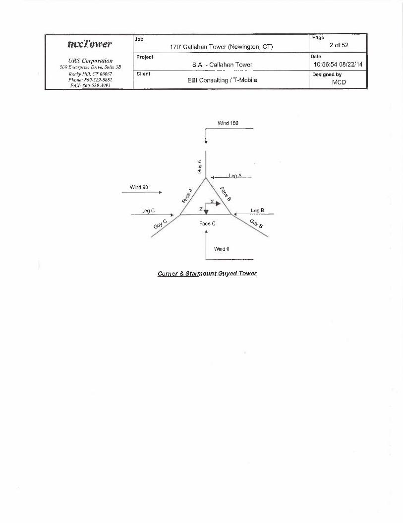
Wind 180
QT7
P.~Q
Wind 90 ~ ~► a, n
~v° P6~
Leg C z ~ Leg E
G~.~G Face C ~rrye
Wind 0
Corner & Sfarmount Guyed Tower

Job Page
tl1 ~ TU11 ~E'~' 170' Callahan Tower (Newington, CT) 3 of 52
URS Corporatiott Project Date
SOOLnre~p~~ise Drii~e, Svite 3R S.A. -Callahan Tower 10:56:54 08/22/14
Rncdi~Fli!!, CT 06067 Client Designed byPhone. 860-529-8882 EBI Consulting / T-Mobile MCDFAh: R60-529-3991
~P '~/~~
Wind 180
G
~~
GUy C
Face Guyed
Tower Section Geometry
Tm~~er Tawer Asserribl~~ Desc~•iptian Sectio~i Niunber Section
Sec7ion Elevation Database Widih o/ Length.SC'(.'(1011.S
j fr ftTl 170.00-155.00 3.42 I J 5.00
T2 155.00-140.00 3.42 I ] 5.00
T3 140.00-120,00 3.42 I 20.D0
T4 120.00-100.00 3.42 I 20.00
TS 100.00-80.00 3.42 I 20.OD
TG 50.00-60.00 3.42 I 20.00
T7 G0.00-40.00 3.42 I 20 OU
T8 40.00-20.00 3.42 I 20.00
'I'9 20 OU-5.00 x.42 I 15.00
1'10 5.00-0.00 3.42 I S.OQ
-- -- - ---
Tower Section Geometry (cont'd)

Job Page
t~zx~'t~tiuer 170' Callahan Tower (Newington, CT) 4 of 52
URS Co~portction Project Date
snnE»r~r~,•rs~ DY;,~~, s~~rr~3a S.A. -Callahan Tower 10:56:54 08/22/14
Rnchj~ Hill, CT 060h7 Client Designed byPno~~~: s~sn-say-~s~z EBI Consulting / T-Mobile MapFMK• 860-519-3997
7owes• To~i~e~• Diagonal Bracing Has Hns Top Gir! Botlarr Girt
Section Elevation Spacing T}pe KBruce I~oriaontals O/jsel Offrct
End
fc /1 Panels iit in
T1 170.00-]55.00 2.42 X Brace No No 3,0000 3.DD00
T2 I55.00-140.00 2.42 X Brace No Yes 3.0000 3.0000
T3 140.00-120.00 2.44 X Brace No Yes 3.0000 3.00Q0
T4 120.00-100.00 2.44 X Brace No Yes 3.0000 3.0000
TS 100.00-80.00 2.44 X Brace No No 3.0000 3,0000
T6 80.00-6D.00 2.44 X Brace No Yes 3.0000 3.0000
T7 60.00-40.00 2,44 X Brace No No 3.0000 3.ODQ0
T8 aU,00-20.00 2.44 K Brace Right No Yes 3.0000 3,0000
T9 20.00-5.00 2.42 1{Brace Right No Yes 3,0000 3.0000
T1~ S.QO-0.00 1.13 X Brace No Yes 3.000 3,0000
Tower Section Geometry (eont'd)
Tower Leg Leg I.,eg Diagoncd Diagonal Diagotiaf
Blevatian Ti~~c Size Grade Tj~e Si>e Gi•ade
Tl I70.00-]55.00 Pipe ROAN 2 STD A572-SD Pipe P1.5x16GA A3G
(50 ksi) (36 ksi)
T2 155.00-140.Q0 Pipe ROHN 2 STD A572-50 Pipe ROHN 1.5 STD A36
(50 ksi) (36 ksi)
T3 140.00-120,00 Arbitrary Shape ROHN 2 STD w/ 1"Solid Rod A572-50 Equal Angle Ll 3/4x1 314x1/4 A3G
(50 ksi) (3G ksi)
T4 120.00-100.00 Pipe ROHN 2 STD A572-50 Pipe P1.Sx] 6GA A36
(~0 ksi) (36 ksi)
TS ]00.00-80.00 Pipe ROHN2.5 S'I'D A572-50 Pipe P1.Sx16GA A36
(50 ksi) (36 ksi)
T6 80.00-60.00 Arbitrary Shape ROHN 2 STD ~v/ I/3rd pipe A572-50 Pipe P1.Sx16GA A36
(SQ Jcsi) (36 ksi)
T7 60.QQ-40.00 Pipe RO~-IN 2.5 STD A572-SU Pipe PI.Sx16GA A36
(50 ksi) (36 [csi)
T8 40.Q0-20.00 Pipe ROHN 2.5 STD A572-50 Pipe Pl.SxI~GA A36(50 ksi) (36 ksi)
T9 20,00-5.00 Pipe ROHN 2.5 STD A572-50 Pipe Pl .Sx16GA A36
(50 ksi) (36 ksi)
TI O S.DO-0,00 Pipe ROHM 2.5 STD A572-50 Vipe A36(50 ksi) (.ib ksi)
Tower Section Geomefiry (cont'd)
Tower Top Girt Top Gir'! Tod Girt Bntfout Cirt Bntmnr Girl Bntt~m Girt
Ele~~niion Type Si;e Grade Type Sine Grade
~t -
Tl 170.00-I~5.00 Pipe P1.Sx16UA A36 Pipe P1.5x16GA A36
(36 I<si) (3G ksi)
T2155.00-140.00 Pipe P].Sx16GA A36 Pipe P1.Sx16GA A36
(36 I<si) (3G I<si)
T3 140.00-]20.00 Equal Angle L] 1/2x1 ]/2x]/8 A36 ~yttalAngle LI 3/4x13l4x1/S A36
(36 I<si) (36 ksi)
T412000-100.00 Pipe P1.Sx16GA A36 Pipe P1.Sx1GGA A36
(36 ksi) (36 ksi)
T51(]~.00-SO.QO Pipe P1.5x16UA A36 Pipe PISx15GA X36

Job Page
~~ZYTOjVei" 170' Callahan Tower (Newington, CT) 5 of 52
URS' Cor~~orafiofr Project Date
snoEnf~,~rrs~D~•r,~~, Suite 3B S.A. -Callahan Tower 10:56:54 08122/14
RacAj~ Hill, [:T [16067 Client Designed byPlrane: 860-529-R~'~i2 EBI Consulting / T-Mobile MCDFAX.- 860-529-399/
Tor{per Tay Gir•( Tay Girt Tnp Girl l~nlinu~ Girt BnUan Girl Boltnii~ GElevation Tjve Sipe Grade T~ve Size Gi•ade
(3G ksi) (36 ksi)TG 80.00-60.00 Pipe P1.~x16GA A36 Pipe Pl.Sx]6GA A36
(36 ksi) (3b ksi)T7 G0.00-40,00 Pipe P1.Sx16GA A36 Pipe Pl.5xl6GA A36
(36 ksi) (36 ksi)
T3 40.00-20.00 Pipe PI,Sx16GA A36 Pipe P1.5x16GA A36(36 ksi) (36 ksi)
T9 20.00-5.00 Pipe PL~x16GA A3G Pipe ROFIN 1.5 SCH XS (Extra A36(36 ksi) Strong) (36 ksi)
T10 5.00-O.Op Flat Bar 3xUQ A36 Flat Bar 3x1/4 A3fi(36 I<si) (36 ksi)
Tower Section Geometry (cor~t'c~)
Traver Nn. A1id Girf hid Girl A1id Gir'1 Hori>nntalElevation of Tiye Si-e Grade T7ye
bfidft Girls
T5100.00-80.00 1 Pipe PLSx16GrA A36 Solid Round(36 ksi)
T7 60.00-40.00 l Pipe PLSx16GA A36 Salid Round(36 ksi)
TS 40.00-2Q.00 None Flat Bar A36 Solid Round(36 ksi)
T9 2 .00-5.00 Node Flat Bar A36 Solid Round(36 ksi)
T10 5.00-Q00 1 F1atBar 3x1/4 A36 Solid Round(36 ksi)
Iloriaontal F~ori_>oitlalStze Grade
A36(36 ksi}A36
(36 ksi)A36
(361csi)A3G
(36 ksi)A36
Tower Section Geometr con~'d
Tower Secottrlarp 5econdar~~Horizontal Secnndar~~ Liner Bracing lm~erBracingSize Inner BracingElevation Hori;m~talTij~e Sine Hnriaonlal Tj~e Grade
Grade
T2 ] 55.0-140.0 Solid Round l .436 Solid Round A572-50(36 ksi) (50 ksi)
T3 140.00-120,OD Equal Angle L] 3/4x1 3/4x1/4 A36 Solid Round A572-50(361tsi) (50 ksi)
T6 80.00-60.00 Lqual Angle I,2x2x3/16 A36 Solid Round A572-50(36 ksil (50 ksi)
~- Tower Section Geom~tby (ca~t'd)

Job Page
~~~~~~'-~ 170' Callahan Tower (Newington, CT) 6 of 52
URS Cotj~oration Project Date
SOOEnie+pr'iseDrlve, Suite 3B S.A. -Callahan Tower 10:56:54 08/22114
RodrnHill, CT 06(167 Client Designed byPho~ze: S6(1-529-&882 EBI Consulting I T-Mobile MCDFAX,-860-529-3991
Tower Gusset Gusset Gi~sselGrade ~djusi,Factw• Adjust, WeigktMult. Double Angle DouhleAnglc
Elevatiai Area Thickness A~ Factar~ Stitch Boll Sfilch Bolt
(per. face) A, Spacing SpacingDiagaials HorizoiitaLs
f' in in to
TI 0,00 D.OQDO A3b I ~ 1 1.05 ~ 36.0000 36.0000
] 70.00-155.00 (36 ksi)T2 0.00 O.~000 A36 I I 1.05 36.0000 36.0000
155.00-140.Q0 (3b ksi)T3 O.QO 0.0000 A36 I 1 1.05 36.0000 36.D000
140.00-120.00 (36 ksi}T4 0.00 O.000O A36 1 1 1.05 36.0000 36.0000
120.00-100.00 (36 ksi)TS 0.00 0.0000 A36 I I 1.05 36.0000 36.0000
f 00.00-80.00 (36 ksi)T6 80,00-60.00 0,00 O.OD00 A36 I I 1.05 36.0000 36.0000
(36 ksi)T7 60.00-40.0 0.00 O.000D A36 I 1 I.OS 36.0000 36.0000
(36 ksi)T8 40.00-20.00 0.00 D.0000 A36 I I 1.05 36.0000 36.0000
(36 ksi)T9 20.00-5.00 0.00 D.0000 A36 1 I 1.05 36.0000 3b.OD00
(36 ksi)T10 5.00-0.00 O.OU 0.0000 A36 1 I 1.05 36.0000 36.0000
(36 ksil
Tower Section Geametr cvnt'd)
m ~ KFactors
Tower Calc Calc Legs X K Surgle Girts Hor-iz. Sea hater
Elevation K K Brace Brace Diags Ha•iz, Brace
Single Solid Diags DiagsA~tg[es Rouiidr X X X X X X X
fW~ f! Y Y Y Y Y Y _ Y -
TI Na No170.00-155.00 I I i I I 1
TZ No No I I I 1 I 1
155.00-140.00T3 Na No 1 1 I 1
140.00-120.00 I I I I I 1
T~1 Nu No]20.00-1Q0.00 I i I 1 1
'1`5 No NoI OQ.DO-80.OQ 1 1
T6 No No I I I I i
50.00-60.00 I I I i I i
T7 No No I I I I I I 1
CD_00-40.00 I I I I I i i
T8 No Na I I I ~ ~ ~ ~ ~40.00-20.00 I I I i I i i
T9 20.00-5.00 No No I I I I 11 I 1
T1Q 5.00-0.00 No No I I I I 1 I S
~No1e; K juctor•.r are applied to member segment lengths. K-braces milhoul inner supporting u~enihets will have [he K facto• is [he vat-of-ylane direction applied to
itie overal/leiiglh

Job Page
tMY.TU1VLl" 170' Callahan Tower (Newington, CT} 7 of 52
URS Cor j~or'atiott Project Date
snn E,n~,Y,~rs~ D~~~v~, s,«r~ 3a S.A. -Callahan Tower 10:56:54 08/22/14
Rnr/,~~Hili, CT0G067 Client Designed byPhi,:~: R6n-s~~-Baez EBI Consulting 1 T-MobileFAX,• R60-529-3991
MCD
Tower Section Geometry (cont'd)
Tamer Leg Diagonal Tod Girt Ballom Uir[ A7id Girl LaigHorizorital Short Hnrizonta!
Elevnlion
rNei FVidlh U Net Widih U Net Width U Net CT Net U Net U Net U
Dedxrct Derlitcl Deduct Widi/i YT'icltlt Widih Widihin ut in Deducl Deduct Deduce Deditet
in in in in
TI 0.0000 1 0.0000 0.75 D.0000 0.75 0.0000 0.75 0.0000 0.75 0.0000 0.75 0.0000 0.75
170.00-T55.00T2 0.0000 ] 0.0000 0.75 0.0000 Q75 Q.0000 0.75 0.0000 x.75 O.000O 0,75 0.0000 Q.75
] 55.00-140.00T3 0.0000 1 0.0000 0.75 0.0000 0.75 ~.0~00 0.75 0.0000 0.75 0.0000 0.75 0.000 0.75
140.00-120.00T4 D.0000 1 0.0000 0.75 0.0000 0.75 U.UllUO OJS (1.0000 0.75 [1.0000 0,75 0.0000 0.75
120.00-100.00TS 0,0000 7 0.0000 U,75 0.0000 0.75 0.0000 0.75 0.0000 D.75 0.0000. 0.75 0.0000 0.75
~ oo.00-ao.00T6 so.00-6o.nn o,0000 i o.0000 o.~s o.0000 o.~s o.0000 o.7s o.0000 o.~s o.0000 o.~s o_0000 o_~sT7 60.00-40.{10 Q.0000 I 0.0000 0.75 0.0000 0.75 0,0000 0.7~ 0.0000 0.75 0.0000 0.75 0.0000 0.75
T8 40.00-20.00 0.0000 I 0.0000 0.75 0.0000 0.75 0.0000 0.75 0.0000 0:75 0.0000 0.75 O.D000 0.75
Ty 20.G0-5,00 0,0000 I 0.0000 0.75 0.0000 0.75 0,0000 0.75 0,0000 0.75 0,0000 0.75 0.0000 0.75Ti 0 5.00-0.00 0.0000 I 0.0000 0.75 0.0000 0.75 0.0000 0.75 x.0000 0.75 0.0000 0.75 0.0000 0.75 ~
~~ Tower Section geometry (cant'd)
Ta~ver Leg Leg Diagarial Top Girt B~tton~ Girt. Mid Girl LortgHnri~onia! Shor[Hori~nnml
Etevcrlion Caz~7ec7ion%1 T}fie
➢olt Size No. Bnit Size NO. BOIL SLL' No, Rn/i Size No, Bolt Sire No, Bol! Si_>e Na BnTt Size Nn.
is in in in in in ~n
Tl Flange 0.7500 4 O.S000 ] 0.500 1 0.5000 I O,S000 l 0.5000 I 0.5000 1170.00-155.00 A325N A325N A325N A325N A325N A325N A325N
T2 Flange 0.7500 4 0.5000 ] 0.5000 1 0.5000 I 0.5000 1 0.5000 I 0.5000 1
155.00-140.00 A325N A325N A325N A325N A325N A325N A325NT3 Flange D.7500 4 0.6250 1 0.6250 I 0,6250 1 0.6250 1 0.6250 1 0.6250
140.00-120.00 A325N A325N A325N A325N A325N A325N A325NT4 Flange 0.7500 4 0.5000 1 0.5000 ] 0.5000 1 0.5000 1 0.5000 I 0.5000
120.00-100.00 A32SN A325N A325N A325N A325N A325N A325N
TS Flange 0.7500 4 0.500(1 1 0.5000 ] 0.5000 I 0.5000 I 0.5000 1 0.5000
100.00-80.Q0 A325TT A325N A325N A325N A325N A325N A32SN
T6 80,00-60.00 Flange 0.7500 4 O.S000 I 0.7500 1 0.7500 1 0.7500 1 0,7500 1 0.7 00 1A325N A325N A325N A325N A325N A325N A325N
"I'7 GQ00-40.00 Flange 0.7500 4 0.5000 1 x,5000 1 0.5000 l 0,5000 1 0.5000 I 0.5000 1A325N A325N A325N A325N A325N A325T1 A325N
T8 40A0-20A0 Flange 0.7500 4 0.5000 1 0.5000 1 0.5000 1 0,5000 1 D.5000 1 0.5000 1A325N A325N A325N A325N A325N A325N A325N
T9 20.00-S.OQ Flange 0.7500 4 0.5000 1 O.SOOD 1 O.SDO(1 1 O.S000 1 0.5000 1 Q_5000A325N A325N A325N A490N A325N A325N A325N
T10 5,00-9.00 Flange 0.750Q 4 0.5000 U 0.5000 0 0.5000 0 0.5000 0 O.SDOQ 0 0.5000A325N A325N A325N A325N A325N A325N A325N
Guy Data

Job Page
~1?.Y~(I1V~Y 170' Callahan Tower (Newington, CT) S of 52
URS Cor~~nration Project ~ Date
son E»t~,~,~;.r~ o~~r~~~, s~~it~ 3a S.A. -Callahan Tower 10:56:54 08/22!14
Roctij~ Hill, CT 06D67 Client Designed byPn~~,~: x<n-szv-x~sz EBI Consulting / T-Mobile MCDFAX.•860-529-3941
Gtt~~ Gul' Guy Irtilicrl °'o Guy ~ Guy L„ Anc7~o~~ Anchor• Anchor• End
Eleva7ion Grarie Siac Teftsion Modi~lv.r Kjeight Radius Azin~z~tli Elcratiai Fi1li~ig~dj. Ef/i~t~~~~~,
f rh ~.~~ ,err fi fr rr152.333 L.HS A 1i2 2690.00 10% 21000 0.517 189.29 106.00 0.0000 -6.00 100%
B 112 2690.00 LO% 21000 0.517 ]8].03 106.00 0.0000 4,00 I~0%C 1I2 2690.00 10°!0 2100 0.517 176.74 107.00 0.0000 10.00 100%
132.438 NHS A 718 7970.00 10°l0 (9000 1.581 173.02 106.00 0.0000 -6,00 100%B 7/8 7970.OD 10°tu 19000 1.581 165.14 106.00 0.0000 4.00 100%
C 7/8 7970.OD 10'%a 19000 1.58] 161,17 107.00 O.000O 10.00 L00%
90 EHS A 7/16 2080.00 1Q°~a 21000 D399 J41.43 106,00 0.0000 -6.00 100°/nB 7(IG 2080.00 10% 21000 0.399 134.86 106:00 0,0000 4.00 100"/0C 7116 2080.00 10°l0 21000 0399 131.91 107.00 0.0000 1D.00 100%
50 EHS A 7116 2050.00 10% 21000 0.394 118.04 ]06.00 0.0000 -6.00 100%
B 7116 2080.00 10% 21D00 0399 113.65 106.00 0.0000 4.00 100%
C 7116 X080.00 10~% 21000 0399 112.29 107.00 0.0000 10.00 100°10
Gu Dafia cont'd
Gut' Maunt Taryue-AF•m Toi•yue-;1rm Tnryue-Arm Toryue-Aron Ta~que-A~•n: To~•yue-Arnt SizeElevation Tjye Syrear! Leg Angle Side Grade T}ye
fif °
152.333 Torque Aim 7.00 0.0000 Chamiel A36 Channel C12x20.7(36 ksi)
132.438 Torque Arm 7.00 0.0000 Cha~mel A36 Arbitrary Shape Cl2x2D.7 ~v/ 8°x318"(36 ksi) plate
90 Corner50 Corner
Guy Data (cont'd)
Gup Dic~ga~al Diagonal Upper Diago+eu! Lower Diaga~al Is Pttll-O[/' Ptdl-Off Ttye Pill-Of/'Si~e
Elevafiou Grade T~pc Sine Siae Sifay. Gt~adcfr
152.33 A572-50 Solid Round 4 No A36 Equal Annle L2x2x3(16
(50 Icsi) (3G ksi)132.44 A572-50 Solid Rouncl A572-SQ Equal Angle
(50 ksi) {50 ksi)
40,00 A572-50 Solid Round No A36 F(at Bar x3/8(50 ksi) (36 ksi)
50.00 A572-50 Solid Round No A36 Flat Bar 4x318
(50 ksi) (36 ksi)
Guy Data (cont'd)
Gup Cahle Cahle Cnhle Cahle Tawer Tai+per 7oia~er Tower
Elevatia~ Weight Wciblu Werght Weight Intercept I~t/cr-cey[ In~ercepl Lilercep[
A R C D A B C D
Ir rn rr~ ~v n~ 1r j ~r t

Job Page
~`I11.TOj1~L~P 170' Callahan Tower (Newington, CT) 9 of 52
URS Coi j~arati0rt Project Date
S00 Enteiyr-ise Drive, Suite 31J S.A. -Callahan Tower 10:56:54 08122114
Rocd~~Hill, CT06Q67 Client Designed byPbnne: 860-519-fi88~ EBI Consulting / T-Mobile MCDFAX: 8C(J-529-3991
Gui~ Cuhle CaGle Cahle Cahle Tower Tower- Tourer Tniver
E)evatian Weiglu WeigTit N~eig/tt Weighi 7niercepl ]rtlercept Intercept Irtlercepf
A B C A A B C D
rh ry rn rn f ,1r 1r _... f152.333 97.87 93.54 9138 339 3.11 2,96
3.2 seclpulse 3.0 sec/pulse 3.0 sec/pulse
132.438 273.54 261.08 254.81 2.43 2.67 2.553.0 sec/pulse 2.8 sec/pulse 2.8 sec/pulse
90 56.43 53.8] 52.63 1,40 1.73 7.662.4 secJpulse 2.3 sec/pulse 2.2 sec/pulse
50 47.10 45,34 44.80 1.33 1.23 1.212.0 sec/pulse ].9 sec/pulse 1 9 seclpulse
Guv Data (cont'd
Toryue Anil Pul! OJ/~ Dingoiaal
Gur Calc Ca/e K, ky K, K~ Kr K„
Elevatio+~ K Kft Si~tgle Solid
Angles Rounds
152.333 No No I I 1 I i132.436 No No 1 1 1 I 140 No No I 150 No No I 1
Guy Data (cont'd)
Torque-Arm Pull Ojf IJingondl
Chip Bolt Sine Nismher• Net Widtli U 13olt Size Numher Nel FVrdth U Solt Si>e Ni~ntber Net N~idth U
Elevntion in Deduct in Deducf in Deduct
(I to ___
in in
152.333 a 0.7500 8 O.OD00 1 0.7500 1 0.0000 1 0.0000 0 O,U000
A325N A325N A325N
132.438 0.7500 8 0.0000 1 0.7500 1 0.0000 l 0.0000 0 0.0000
A32~N A325N A325N
90 0.6250 0 0.0000 0.75 0.0000 0 0.0000 I 0.0000 0 0.0000 1
A325N A325N A325N
SU U.bZSU U O.000U U.'/5 0.UD00 0 0.0000 I 0.0000 0 0.0000 1A325N A325N A3?SN
Guy Pressures
EIL'VLtll0I1 LfJCttl(Ol! ICL
1t t y.+f152333 A 7317 21 IS
B 78.17 21 16C 81.17 21 16
132.438 A 63.22 20 ISB 68.22 20 I SC 71.22 20 15
90 A 42.00 18 13B 47.00 ] 8 14
~~~~Thicla~ess•
in0,50000.50000.50000.5000O.S0000,50000.5000Q,5000

Job Page
f11YTO1NC'i' 170' Callahan Tower (Newington, CT) 10 of 52
URS Coi~~nration Project Date
snn E~~t~-,~,~~.s~ D~•~v~, s~~tr~ 3s S.A. -Callahan Tower 10.56:54 08/22/14
Rncb~>Hi11,CT06067 Client Designed byPho,r~: 86n-szv-xxs2 EBI Consulting / T-Mobile MCDFAX.- A60-529-3991
Grip Gtr~~ _ N= g= Ice
Elevation Location Tce Thiclaiersf /! p.s/' ucj in
C 50.00 18 l 4 .0.5000
50 A 22.OQ i G 12 0.5000
B 27.00 I6 12 0.5000
G 30.OQ 1 G 1?. 0.5000
Guy-Tensioning Information
Tcnipeinhire .J/ Time Ul Teusimiing
O F 2lYF ~t!! F bO F NO F IOfI F 120 r
Gl{p H V !n!!!ul b+le~cept Idiligl INercepl hiilin! Lilercep! Init(uf /nlercepl G~ilia/ !rr/c~cepl b~ifinl Inlet ce/>! Jnifief lrtlrirrpJ/:'lci~alinn 7ertsinn Trna'inu T•u.~inn Trnsion Tension Tensim~ Tmesinn
!~ R !i !L L+ fh h ~h [f !h )r Ih ry !b T Ib T1
IS2.337 A 104 04 158 37 3049 3.OD ?929 i l~ 2809 3 25. 3690 399 '_371 7.Si 2453 3 77 2336 3.90
T3 10-0 04 I dR33 30R3 2.72 2951 2.R4 2H2~ 2 97 2fi90 3 I I 25(,0 3 2fi 2431 3 d3 2303 3 62
C 105 04 14293 3110 2 57 290+9 2.49 2829 2 K2 2690 2.9G ?552 3.1? 2d1A 3 3t] 2278 3 49
132.d3R A I OA.04 13R 4A 9153 255 37fi4 2!7 K3fi(r Z]9 7970 293 7i7fi 3 08 71 Ag 3 25 6798 3 4]f3 104.04 I?.G 4d 9279 Z30 R442 2.41 3408 254 7970 2h7 7538 2.R2 7109 299 (fi8h 31R
C 105 04 122 d4 9;72 2J7 5902 2.28 R43i 241 7970 3.55 7508 ?.7Q 70511 2 RR (S97 3 (17
90 A 104 03 9( 00 2578 134 2A 1 1 Lf 4 2235 13fi 20H0 1.9U U I (> 2D(t 175$ 3 2S 159( 2 47
104.03 8(.00 2b?R 1.37 2-045 1,47 2212 I i9 20R0 1.73 19ti0 LR9 1723 209 ISd9 232L 105.03 N0.00 26fi~ 1,30 24fiH 1.40 2273 I.52 2080 I.GG 1889 I.82 1700 203 1516 227
SO A 10403 Sfi.00 2797 0,99 2557 I.OB. 2317 119 2080 133 1846 LSU I(IG 171 1393 198
i3 104A3 d(~0 2854 0,90 ?594 0,9I 2]~li I.I~ 2080 1,3 IN?7 I,dO 1580 I (7 1342 19I
C 10503 40 ~0 ~ 3RR3 O, R7 2fi17 09b 2347 I,t17 20Y0 I.?I I81( 1,3R I$$9 I (I 1312 I.91
Feed Line/Linear A purtenances -Entered As Round Or Flat
Description Fnce Allow Conrporierrt P/acernent Face Lateru! # # Clear Wid1G nr Peeimeter I~ei~ltl
a• Shield Tye Orfset Offset Per- Syncing Dia~rreter•
L¢,Q %t in (Prue Fib) _Row i~~ en !1i p!f
LMR-400 B Yes Ar (CfAe) 50.00 - 6.00 0.0000 0.48 2 2 0.4100 0.4100 0.07
(13!32FOAM)(Town
7/B A Yes Aa' (CfAe) 120.00 - 6.00 D.0000 0 12 9 1,0000 1.1 ] 00 OS4
(AT&T)~vr-vg122st-br B Yes Ar (CfAe) 120.00 - 6.0~ 0.000 -0.5 2 2 1.0000 0.7500 0.25
da(AT&T)
FB-L98B-002 B Yes Ar (CfAe) 120.00 - 6.00 O,000O -x.497 1 I 1.0000 03750 1.00
{AT&T)] 1/4 C Yes ?u (CfAe) 14],00 - 6.00 0.0000 0.23. 9 9 1.0000 1.5500 O.Gfi
(Nextel/Sprint
2" Rigid C Yes Ar (CfAe) 143.00 - 6.D0 2.0000 0 2 2 1.0000 2.0000 2.80
Conduit(Cleai~vire)
1518 B Yes Ai' (CfAe) ] 62A0 - G.00 0.0000 -0.2 12 6 I.SOdO 1.9800 ] 04
(T-MoUile)1/2 B No Ar (Leg) 167.00 -1.00 0.0000 0, I6 1 1 0.5800 0.5300 025
(Town -Dish)1 S/S B No Ar (Leg) 170.00 - 6.00 Q.(1Q~0 0.15 2 1 1.6250 1.4800 1 A4
(Town)7/8 B No Ar (Leg) 170.00 - 6.00 0.0000 0.1 2 I 0.8750 I .l 100 0.5=F
(Town)112 S No Ar (Leg) 170.00 - 6.00 0.0000 0.1 1 I 0.5800 0.5800 O.ZS
(Town)

Job Page
flZ.l"~~j1~L'~" 170' Callahan Tower (Newington, GT) 11 of 52
URS Corl~araiion Project Date
500 Ente~prisc Drive, Sttile 3B S.A. -Callahan Tower 10:56:54 08/22/14
Rocfi~Hill, CT 06067 Client Designed byPno„~: s6n-sz9-sssz EBI Consulting / T-Mobile MCDFAX.•860-529-3991
Description Face Allo~~~ Con:ponutt Placement Face Lateral # # Clear Widtlt w• Peri~neter~ FYeightor Shield Tide r~rrr~, Offset Per Spacing Diameter
Le (I in (Frac FF►') , Roiv in in in 1~
I/2 C Yes Ar (CfAe) ] 46.00 - 6.00 2.0000 0.2 2 I 0.5800 0.580 025
(Cleanvirc)1/2 C Yes Ar(CfAe) ]46.00-G.~O 2.0000 U.] I I 0.5800 0.5800 0.25
(Cleanvire)1 5!8 B Yes Ar (CfAe) 163.00 - G.00 2.0000 0.18 6 3 1.9600 1.9800 1.04
(T-Mobile(Proposed)1
Feed Line/Linear Ap~aurtenances Section Areas
Tawei~ Tower Face Aq Ar C~A~ C,~A~ WeighlSection Efevatiott In Face Out Face
%t (r' tr' Ti' Rz !bT> »o.00-iss.00 n o,000 o.000 o.000 o.ono o.00
B 16.058 0.000 0.000 0.000 191.43C 5.168. 0:000 0.000 0.000 0.00
T2 155.00-140.00 A 0.000 0.600 0.000 OA00 0.0aB 27.587 x.000 0.000 0.000 335.70C 8.055 0.000 O.000 O.ODO 27.24
T3 140.00-120,DD A 0,000 0.000 0.000 0.000 0.00B 36.783 O.000 0.000 0.000 447.60C 38.933 0.000 0.000 0.000 245.80
T4 120.00-100.00 A 16.650 0.000 0.000 0.000 129.60B 39.908 O.000 0.000 O.D00 477.60C 3.8.933 0.000 0.000 0.000 245.80
TS IOO.QQ-80.00 A ] 6.650 0.000 0.000 0.000 129.60B 39.908 0.000 0.000 O.DQO 477.60C 38.933 0.000 0.000 0.000 ?45,80
T6 80.00-60.00 A 16.65Q 0.000 0.000 0.000 129.00B 39.908 0.000 0.000 0.000 A77.60L 38.933 0.000 0.000 0.000 245.80
T7 60,00-40.00 A ] b.650 0.00 0.000 0.000 129.60B 40.592 0.000 O.000 Q.000 479.00C 38.933 0.00 0.000 0.000 245.80
TR 40.00-20.00 A 16.650 0.000 0.000 O.000 129.6B 41.275 Q.000 0.000 0.000 4~i0,4~C 38.933 0.000 0,000 0.000 245.80
T9 20.Q0-5.00 A 11,655 0.000 0.000 0.000 90.7?B 28.892 0.000 O.000 0.000 336.28C ?7.253 0..000 0,000 0.000 172.06
T10 S.QO-Q.00 A 0.000 0.00 0.000 0,000 0.00B 0.000 0.000 O.000 0.000 0.00C 0.000 0.000 0.000 0.000 0.00
Feed Line/Linear Appurtenances Section Areas -With Ice
Toia~er Tor~~er Face Icz Air AF• C.,A,~ G',~A4 YYeighiSec~in~r Elevation or Thickness h~ Fnce Oi~t Face
f ceg to fir' rr' tt~ /t' rh
Tl 170.OD-]55.00 A 0.500 Q.000 0.000 0.000 0.000 0.00B 263118 0.000 0.000 O,000 484.17C 9.918 0.000 O.D00 0.000 0.00
T2 155.00-]40.00 A 0,500 0,000 O.D00 0.000 0,000 0.00B X3.837 0.000 0.000 0,000 839.48

Job Page
tIZC~OIVE'Y 170' Callahan Tower (Newington, CT) 12 of 52
URS Corporation Project Date
sonE»r~,~,-cs~D~~~v~, s~~tt~jx S.A. -Callahan Tower 10:56:54 08/22/14
Roc%~ Hill, CT 06067 Client Designed byPhone: 860-529-RR82 EBI Consulting / T-Mobile MCDFAXi 860-529-3991
Tower Tnwer Face Ice Ap ~ AF~ C,iAA C,~A,~ YVeight
5ectian Elevation or 7hiclmess In Face Otsi Faceft Lei „ in,. (t' fit ft' ~' Ih
C ~ 12.855 2.450 0.000 0.000 66.14T3 140.00-120.00 A 0.500 Q.000 0.000 0.000 0.000 0.00
B 58.450 0.000 0.ODO 0.000 1119.31C 28.267 39.000 0.000 O,000 673.73
T4 124.00-100.00 A 0.500 3.517 28.133 0.000 0.000 407.13B 63.658 2.917 0.000 O.00D 1195.65C 28.267 34.000 0.000 0.000 673.73
TS J 00,00-80,00 A 0.500 3.517 28.133 0.000 x.000 40213B 63.658 2.917 0.000 0.000 1195,65C 28.257 34.000 0.000 0.000 673.73
T6 R0.00-60.00 A D.500 3.517 28,133 0.000 0.000 407.L3B G3.65R 2.917 0.000 Q,000 1195.65C 28.267 39.000 0.000 O.00D 673.73
T7 60.00-40.OQ A 0.500 3.517 2.133 U.ObO O.ODO 407.13B 64.833 3.600 b.000 0.000 1206.59C 28.267 39.000 0.000 0.0(10 673.73
T8 40.00-20.00 A 0.500 3.517 28.133 0.000 UA00 407.13B 66.00$ 4.283 0.000 D.000 1217.54C 28.267 39.000 0.000 ~.00ti 673.73
T9 2Q.OD-5.00 A Q50~ 2.462 19.693 0.000 0.000 284.99B 46.206 2.998 0.000 O.00D 852 ~SC 19.787 27.300 0.000 0.000 471.6]
T1Q 5.00-0.00 A D.500 O.00D 0.000 0.000 O.ODD 0.00
B 0.000 0,000 0.000 0,000 Q.UO
C 0.000 0.000 0.000 0.000 0.00
Feed Line Shielding
SLCII077 r[~arr~~, ra~~ ~R AN .rF nFr« r~~
n r.~' r~1 r~ r'Tl 170.00-155.00 A 0.000 0.000 0.000 0.000
B 1.919 4.408 0.000 O,000C 0.000 0.00 0.000 O.ODO
T2 155.0-140.00 A 0.000 0.000 0.000 0.000B 4.668 11.438 0.248 0.373C 0.575 1.703 0.030 0.055
T3 140.00-120.00 A 0.000 0,000 0.000 0.000B 0.000 5.522 6390 9.617C 0.000 6.611 6.652 11,514
T4 120.00-100,00 A 2.853 8.279 0.000 0.000B 5.626 13.818 O.000 O.ODOC SASS 13.999 0 D00 0.000
TS 100,00-80.00 A 2.853 8.411 0.278 0.527B S.b26 14.038 0.547 0:880C 5.458 14.22 0.531 0.892
T6 80.00-60.00 A 2.853 9334 1.110 2.110B 5.626 15.579 2.188 3.522C S.~i58 15.783 2.123 3.568
T7 60.OQ-40.00 A 2.853 8.411 0.278 0.527li 5,743 14.532 0.558 0.911C 5..458 14.222 Q.531 0.892
T8 40.00-20.00 A 2.U~t4 6.368 0.000 R.0~0B 4.198 11377 0.000 O.00QC 3.91 D 10.768 0.000 O.000
T9 2Q~0-5.00 A 1.474 4.567 0,000 0.000B 3.026 8.159 0.000 0.000

Job Page
tf2 \: TU I i'C'f" 170' Callahan Tower (Newington, CT) '13 of 52
URS Corporation Project Date
san E.:r~,p,~ts~ D,~r~~~, s:~tr~ ~a S.A. -Callahan Tower 10:56:54 08/22/14
Rnc6i~Tlilf, CT 06067 Client Designed byPHone. h'C~0-529-RSA2 EBI Consulting / T-Mobile MCDFAX. R60-.529-3991
.rGC11 X71 EIL'VOtf071 F'QCL' f~H ~11~ ~F ~F
Jce Ieeit ft' f ~ 1'i' f ~
C 2.819 7.722 0.000 0.000'T] 0 5.00-~.DO A 0.000 0.000 O.DOD 0.000
B 0.000 0.000 0.000 x.000c o.000 o,000 o.000 a.000
__ --~Feed Line Center of Pressure
Section E/~valion CPx CPz CP,r CPSIce Ire
ft in is in in
Tl 170.00-155.00 3.~35b -(1.6604 3.1499 -0.2825T2 155.00-]40.00 3.4670 -1.2527 3.3095 -0.7n70
T3 140.00-120.00 1.4887 1.1285 1.7487 0.8207T4 120.00-100.00 0.3619 0,0422 0.5906 -0.1174TS 100.00-80.00 D3545 0.0485 0.598? -0.0995
TC 80.00-60.00 03715 0,0713 0.6858 -0.0425T7 60.00-40.00 D.4306 0.0904 0.6D91 -0.0909T8 40.OD-20.00 0.5096 0.1124 x.5722 -0.1277
T9 ?0.00-5.00 0.4960 0.1105 0.5608 -0.1218Tio s.ao-o.00 o.0000 o.0000 o.0000 o.0000
Discrete Tower Loads
Description Face Offsef Ojjrels: A7imitth Placement C:~~7,~ Ca~1n YT'elghtor Tjpe FIo~•a Adjirstincnt Fr•orit SideLeg Lateral
ijert
.it r r1 r~' rr~rrr~
D54CO3F36U-D S' Omni A From Leg 1.00 0.0000 175.00 No Ice 2.SG 2.56 30.00
(Toni+n) (1 00 U2" Ice 3,28 3.23 48.530.00
SC~73-FIFILDF B From Leg 1.00 0.0000 175.00 No [ce 1.44 1.44 17.00
(Town) 0.00 112" Ice 1.74 1.74 29.430.00
SC473-HFILDF C From i.eg 1,00 0.0000 ]75.00 No Ice 1.~1~1 ].4~ 17.00(Totem) 0.00 U2" Ice 1.74 ].74 29.43
O,DOTTA 432-83H-OIT A Node 0.0000 170.00 No Tce 1,63 0.95 25.00
(Town) 1!2" Icz 1.81 1,09 37.4
Pirod 4' Side Mount Standoff A From Leg ~.SD 0.0000 168.00 No Ice 2.72 2.72 50.00
(1) O.DO IJ2"Ice 4.9] 4.9] 89.00
(Town) 0.00Pirod 4' Side Mount Standoff B From Leg 2.50 0.0000 168.00 No lce 2,72 2.72 SQ.00
(I) 0.00 L/2" Ice X1.91 4.9] 89.00
(Town) 0.004' Standoff C From Leg 0.50 0.0000 1GR.00 No lie 3.42 3.42 111.16
(Town) 0.00 I/2" Tce 3.67 3.67 147.200.00
844H90T11~XY A From Leg 1.00 0,0000 143.00 No ]ce 3.06 3,73 14,00
(Cleaiwire) 0.00 112" )ce 339 4.10 40.30

Job Page
~~~~d~~ 170' Callahan Tower (Newington, CT) 14 of 52
URS Cot^poratian Project Date
SOO~nterpriseDrive, S,~tr~3a S.A. -Callahan Tower 10:56:54 08/22/14
Rock~~Hili, CTQG067 Client Designed byPhone. 860-529-8842 EBI Consulting / T-Mobile MCDFA Y•86n-529-3991
Description Face Of/set OfJ.'sets: Azimuth Placenvenl Cn~1.a C;~A.~ YVeight
or Type Flare .Adjustment Fron! Side
Leg Lalera!Y'er•tfi .f ft' /r' thrt
__ no.00
844H90T11EXY B From Leg 1.OD 0:0000 13.00 No lce 3.06 3.73 14.D0
(Clearwire) 0.00 I!2" Ice 339 4,10 403Q
D.00844H90T1lEXY C From Leg 1.00 O.000O 143.00 No Ice 3.06 3.73 ]4.00
(Cleanvire) 0.00 112" Tce 3.39 4.10 40.300.00
(~}) 844G65VTZASX A From Leg 1.00 0.0000 141.50 No Ice 6.55 5.63 41.55
w/Mount Pipe D,00 ll2" Ice 7.25 G.73 98.42
(Sprint) 0.00(4) S$4G6NTZASX B From Leg 1.00 0.0000 141.50 No Ice 6.55 5.63 41.55
w/Mount Pipe 0.00 1/2" Ice 7.25 6.73 98.42
(Sprint) 0.00(~) 844G65VTZASX C From Leg 1.00 0.0000 141.50 No Ice 6.55 5.63 41.55
w/Momit Pipe 0.00 1/2"Ice 7.25 6.73 98.42
(Sprint) Q.00RRUS-] 1 A From Leg 1.00 0.0000 141,50 No Ice 3.26 1.38 50.00
(Sprint) 0.00 1/2" Ice 3.50 1.56 70.870.00
RRUS-1 l A From Lag 1.00 Q.0000 141.50 No lce 3.26 1.3R 50.00
(Sprint) 0.~0 112" Ice 3.50 1.56 70.870.00
RRU3-11 C From Lei 1.00 0.0000 141.50 No Ice 3.26 138 50.00
(Sprint) 0.00 1/2" ]ce 3,50 1.56 70.R70.00
Pirod 12' T-Fratne Sector A From Leg 0.50 0.0000 141.00 No Ice 13.60 13.60 465.00
Mount (1) 0.00 1/2" Ice 18.40 18.40 600.00
(Sprint) 0.00Firod 12' T-Frame Sector B Prmn Leg 0.50 0.0000 ]41,00 No Ice 13.60 13.6Q X65.00
Mount (1) 0.00 112" lce 18.40 18.40 600.00
(Sprint) 0.0~Pirod 12' T-Frame Sector C From Leg. 0.50 O.UQDO 141.Q0 No Ice 13.60 13.60 465.00
Mount (l) 0.00 1/2" Ice 18.40 18.40 600.00
(Sprint) 0.00Pirod 12' T-Frame Sector A From Leg ISO 0.0000 120.00 No Ice 13.60 13,60 465.00
Mount (1) 0.00 1 /2" Ice 18.40 18.40 600.00
(AT&T) 0.00Pirod 12' T-Frame Sector B From Leg I.50 0.0000 120.00 No Ice 13.60 13.60 465.00
Mount (1) 0.0~ 1/2" Ice 18.40 18.40 600.00
(AT&T) 0.00Pirod 12' T-Frame Secior C From Leg 1.50 0.0000 120.00 No Ice 13.60 13.6 465.00
Mount (1) 0.~0 ]/2" Ice 18.40 18.40 600.00
(AT&T) 0.00(2) 7770 w/mount pipe A From Leg 3.00 0.0000 120.00 No Ice 6.02 4.10 57.25
(AT&T) 0.00 112"Ice 6.47 4.75 I~1.]4
0.00(2) 7770 w/mount pipe H From Leg 3.00 0.0000 ] 20.00 No Ice 6,02 4.10 57.25
(AT&T) 0.00 1/2" Ice 6.47 4.75 11.14D.00
(2) 7770 w/mount pipe C From Leg 3.00 0.000.0 120.00 No Ice 6.02 4.10 57.25(AT&T) 0.00 1/2" Ice b.47 4.75 ] Ol .14
0,00(2) LGP21900 A From Leg 2.00 0.0000 120,00 No Ice 0.23 0.12 2,50
(AT&T) 0.00 1(2"Ice 030 0.17 4.70O.DO
(2) T,GP21900 B From Leg 2.00 0.0000 •120.00 No Ice 0.23 0.12 2.50
(A']'&T) 0.00 1!2" Ice 030 0.17 4.70

Job Page
~)1~"TOWLf" 170' Callahan Tower (Newington, CT) 15 of 52
URS Cofpar~nt[on Project Date
SOOEnte~pri.reDi-ive, Suite 3B S.A. -Callahan Tower 10:56:54 08/22/14
Radn= Hill, CT 06067 Client Designed bypha„~: ~6n-sz9-~s8z EBI Consulting / T-Mobile MCDF~1X.~ 860-529-3991
Ueseripiio~t Face Offsef Offsets: Azimuth Placr~i~ent C,T~1_s C,i.~.a Weightor~ Tjne Hora Rdjustnienl Frroiit SideLeg Lateral
Vertft ft ft' /i2 !h
f
rt -0.00
(2j LGP21900 C Frwn Leg 2.00 0.0000 120.00 Na Tce 0.23 O.12 2.5~(AT&T) 0.00 1/2"Ice 030 0.17 4.70
0.00(2) 7070.5 RET A From Leg 3.D0 0.0000 120.00 No Ice 0.40 0.20 220
(AT&T} 0.00 12" Ice 0.49 0:27 5.13O.DO
(2) 7070.5 RET H From Leg 3.00 0.0000 120.00 Nn Ice 0.~0 0.20 2:20
(AT&T) 0.00 ]!2" Ice 0.49 0.27 5.130.00
(2) 7070.5 RET C From Leg 3.00 0.0000 120.00 No Ice 0.40 0.20 2.20(AT&T) 0.00 ]/2"Ice 0.49 0.27 5.13
0.00(2) T~YIA A From I.eg 2.00 0.0000 120.00 No Ice 1.06 0.45 20.00(AT&'I') 0.00 1/2" Ice 1.21 0.57 26.53
0.00(2) TMA B From Leg 2.00 0.0000 120.00 Nn Ice 1.06 0.45 20.0(AT&T) 0.00 1/2"Ice 1.21 0.~7 26.53
0.00i (2) TMA C From Leg 2.00 0.0000 120.00 No Ice 1.06 0.45 2Q.00
(AT&T) 0.00 112" [ce 1.21 0.57 26.530.00
AM-X-CD-16-65-OOT w/ 96" A From Leg 3.00 0.0000 120.00 No Ice 8.50 6,30 74.05pipe 0.00 112" Ice 9.15 7.48 136.21
(AT&T) 0.00AM-X-CD-16-65-OOTw/ 96" B From I,eg 3.00 0.0000 120.00 No Ice B.50 630 74.05
prpe 0.00 1/2"Tce 9.15 7.48 136.21(AT&T) 0.00
AM-X-CD-16-65-OOTwr 96" C From Leg 3.00 OA000 120.00 No Ice 8.50 630 74.05pipe 0.00 1/2" Ice 9.15 7.4& 136.21
(AT&T) 0.00(2) RRUS-11 A From Leg 2.00 0.0000 120.00 No Ice 2.07 I.OS 44.00(AT&T) 0.00 lit" Ice 226 1.23 58.64
0.00(2) RRUS-I l B From Leg 2.00 0.0000 120.00 No lce 2.D7 1.08 44.00(AT&T) 0.00 1/2" Ice 2.26 ].23 58.64
0.00(2) RRUS-I I C From Leg 2.00 0.0000 120.00 Na Ice 2,07 1.08 44.00(AT&T) 0.00 (l2" Ice 2.26 1.23 58.64
0.00DC6-4~-60-18-8F A From Leg 0.50 0.0000 12~.OD No Ice 2,45 2.45 38.25
(ATRT) 0.00 1!2" Tce 2.95 2.95 64.620.00
(2) GPS C None O.0000 50.00 No Ice 1.00 1.00 10.00(Town} 112" Ice I.50 I.50 15.OD
APXI6DWV-] 6~WS A From Leg 3.00 0.0000 163.00 No Ice 7.0? 2.15 4(1.70(T-MoUile) 6.00 ll2" Tce 7.52 2.49 73.65
0.00LNX-651 SDS-VTM A From Leo 3.00 0.0000 163.00 No Ice 11.45 7.70 50.00
(T-MoUile) -6.00 I!2" Ice 12.06 829 1 ]S.S70.00
APXI6DVW-1GWVS B FrotnLeg 3.00 0.0000 ]63.00 Nolce 7A7 2.15 40.70(T-MoUile) 6.00 1!2" ]ce 7.52 2.49 73.65
0,00LNX-6515DS-VTM B From Leg 3.00 OA000 163.Q0 No Ice 1 1.45 7.70 50.00
(T-Mobile) -6.00 1/2"ice 12,06 8.29 115,870.00

Job Page
~~~~~~~ 170' Callahan Tower (Newington, CT) 16 of 52
URS Cor^porntion Project Date
sooE~uep~~tseU~~Fve, Sirite3B S.A. -Callahan Tower 10:56:54 08/22114
Roc~j~7Til1, CTObOb7 Client Designed byPhone: 860-529-8882 EBI Consulting / T-Mobi(e MCDFAX.•850-529-3991
Descr•iy[iai Face Of/se! OjJsets: ,4aimulh Placerne~at C~,9.~ ~ C,~A,~ YYeight
or Tvpe Floe Adjustment Frw7t Side
Leg LateralVerfri ~ ~, j~~ riz thrtr:
APXIbDWV-16WVS C From Leg 3.00 0.0000 ]63.00 Nolce 7.07 2.15 40.70
(T-Mobile) 6.00 1/2" Ice 7.52 2.49 73.65
0.00LNX-6515DS-VTM C From Leg 3.00 0.0000 163.00 No Ice 11.45 7.70 50.00
(T-Mobile) -6.Q0 1(2" Ice 12.06 8.29 115.87
0.00(2) TMA A From Leg 3.00 0.0000 163.00 No lce 1.06 0.45 2D.00
(T-Mobile) 6.00 112" Ice 12] 0.57 26.530.00
(2) TMA B From Leo 3,Q0 0.0000 163.00 No Ice 1.06 0.45 20.00
(T-Mobile) 6.00 1!2" Ice 1.2] 0.57 26.53
0.00(2) TMA C From Leg 3.00 0.0000 7 G3.00 No ]ce ] A6 0.45 20,00
(T-Mobile) 6,OQ ]/2" lce 1.21 0.57 26.530.00
Pirod 12' T-Frame Sector A None 0.0000 163.00 No Ice 13.60 13.60 465.00
Mount (1) I/2" Ice 18,40 18,40 600.00
(T-Mobile)Pirod 12' T-Frame 5ectar B None O.000O 163A0 No Ice 13.60 13.60 465.00
Mouirt (1) 1/2"Ice 18.40 18.40 600.00
(T-MoUile)Pirod 12' T-Frame Sector C None 0.0000 163.00 No Ice 13.60 ] 3.60 4b5.00
Mount (1) 1/2" Ice 18.40 18.40 600.00
(`I'-Mobile) ..,..~,,,,...m_,_~- - ,m,~.,~~,..,,.. ~.
Descriptia~ Face Dish Offset OJj`.rets: AzirnutA 3 dB Elevation Outside Aper7ure iFeight
ar Tjpe Type Horz Adjustment Beam Dia~nelei• Area
Leg Latetnl WidthVcr~t(t ~ ft f ft~ Ib
VHLP800-11 A Paraboloid From 1.00 Wmst 145.60 2.50 Na Ice 4.90 49.UU~
w/Radorne Leg D,00 1/2" Ice 84.00 282.00
0,00VHLP2-180 A Paraboloid w/o From 1.00 VVocst 145.60 2.00 No Ice 3.14 25.00
Radome Leg 0:00 1(2" Tce 3.41 42.490.00
VHI.P2-180 C Paraboloid w/o From 1.00 Worst 146.00 2.00 No Ice 3J4 25.00
Radome Leg 0.00 1/2°lce 3.41 42.49o.00
RFS SC2-W100BC C Paraboloid From I.00 Worst 167.00 2.OQ No Tce 3.14 20.00
w/Shroud (HP} Leg 0.00 J/2" Ice 3.4] 37,500.00
Tower Pressures - No Ice
G„ = r. rzs

Job Page
~Xt~Ta~~k 170' CaNahan Tower (Newington, CT) 17 of 52
U,RS COY~10Yatio~t Project Date
500 Enterpr•!se Drive, suite ~a S.A. -Callahan Tower 10:56:54 08/22/14
Roc%~ Hil/, C,T Ofi067 Client designed byPhone: 860-529-8B82 EBI Consulting / T-Mobile MCDFAX.• 860-.i29-399/
Sectio~i ~ Kl 9;, A~ F AF Ax Af~a Leg C~A~ C,4A,~Elevalion a °fn h~ Oul
c Face dace
rr r~ sr r~~ e r~ ~~ ft, r,~ ft~Tl 162.50 1.577 26 54.264 A 0.000 14.454 5.938 41.08 0.000 0.000
170.00-155.00 B 0.000 28.593 20.77 0.000 0.000C 0.000 19.621 30.26 0.000 0.000
T2 147.50 1.534 25 54269 A 0.537 16.065 5.938 35.76 0.000 0.000155,00-140.00 B 0.290 38.485 15.12 0.000 0,000
C 0.507 23.545 24.69 0,000 0.000T3 130.00 1.48 24 73.288 A 25.062 O.000 ] 1.198 44.68 0.000 0.000
140.00-120.00 B 18.672 36.783 20.19 0.000 0.000C 18.2]0 38.933 19.60 0.000 0.000
T4 110.00 1,411 23 72358 A 0.000 32.757 7.917 24.17 0.000 0.000120,00-100.0 B O.000 53.23 14.87 0.000 0.000
C 0.000 52.436 15.10 0.000 0.000TS 90.00 ].332 ?2 73.192 A 0.783 34.281 9.583 27.33 0.000 O.000
]00.00-80.00 B 0.513 54.767 17.34 0.000 0.000C 0.529 53.959 17.59 0.000 0.000
T6 80.00-fi0.00 70.00 1.24 20 72.550 A 11.992 24.762 8.837 24.04 0.000 0.000B 10.914 45.248 15.73 0.000 0.000C ]0.979 44.440 15.95 0.000 0.000
T7 60.OD-40.00 50.00 1.126 1 S 73.192 A 0,783 34.281 9.583 2733 0.000 0.000B 0.502 55334 17.16 0.000 O.00DC 0.529 53.959 17.59 0.000 0.000
TS 40.OQ-20:00 30.00 1 16 73.192 A O.D00 31.999 4.583 29.95 0,000 0.000B 0.000 54.470 17.59 0.000 0.000C O.000 52.416 18.28 0.000 0.000
T9 20.00-5.00 12.50 1 16 54.894 A 0.000 23.40] 7.188 30,71 0.000 0.000B 0.000 39.086 1839 0.000 0.000C 0.000 37.654 19.09 0.000 O.D00
TlOSAO-0.00 2.50 l ]6 4.816 A i.120 2.576 2.576 69.70 0.000 O,QDOB 1.120 2.576 69.70 O.000 O.000C 1.120 2.576 69.70 0.000 0.000
Tower Pressure - Witf~ Ice
GH = ~. rzs
Secliat _ KZ 9z lz Ac F ,~it~ AR Ar~g I Pg C~A;~ CaA~Elevation a % In Out
c Face Face
ft sf r~~ l' ~: ~i' ft' Tr' fi' tr'Tl 162.5O 1.577 ]9 tl,SfiUU 55.514 A Q.000 21.436 8.438 343( O.CNIU O.000
170.Q0-155.00 B Q.000 43.336 ]9.47 11,UOIl 0.000C 0.000 31.35 4 26.91 (1.000 0.000
T2 147.50 1.534 ]9 (1.5(IUfi 55.519 A 0.537 24.427 8.438 33.14 u.i10(i 0,000155.00-140.00 B 0.]65 57.327 14.hk O.gUU 0.000
C 2.93? 36.079 21.ti1 (1.f10U 0.000T3 130.Q0 1.48 18 U. UU(1 7 .955 A 22284 7.961 17.d2U 38.Q8 1).110(1 0.000
]AO.OD-120.00 B 17.667 60.889 17.08 u.n[~a 0.000C 54.771 29.61(, 15.9Q It.nUu tl.(i01)
T4 110.00 1.411 17 0.5Lin0 74.025 A 28.133 233~W ]]:2~0 21.85 O.fiO(i II.U(Ih120.00-100.00 B 2.917 77.9x7 13.91 n.IiOn q.Obfi
C 39.000 ~a2.37%~ 13.82 fl.utif~ (I.OUOT5100.00-80.00 90.00 1332 16 q,gnoo 74.858 A 28.666 2d.9?(i 12.917 24.10 o.ucrn O.00D
B 3.096 79.441 15.65 o.t~uu 0.(70DG 39.1fi8 43.865 15.56 U.000 p,fl0ff
T6 80.00-60.00 70,00 1.24 15 U,S(100 74.21f, A 4].348 1.052 I1.05~~ 2Q.33 ~~.Un(i q.fi0[~

Job Page
111 ~ TO1V~'/" 170' Callahan Tower (Newington, CT) 18 of 52
URS Coiforation Project Date
SOOEnterpri.reDri»e, S~dte3E S.A. -Callahan Tower 10:56:54 08/22/14
Roclr~~Hi/l, CT06D67 Client Designed byPhase.• R60-529- 882 EBI Consulting / T-Mobile MCDFAK• 860-529-3991
Sec(iort _ h`, 9: t, A~ T AF AR Ar~~ Leg Cn~,i ~':i~:iElevation a % la Out
c Face Face
ft ft sJ i1r f.~1 e j!' ft' rt' R~ ft'B 14.719 66.949 13.54 0.000 0.000
C 50.757 31.353 13.47 0.000 0.000
T7 60.00-40.00 SOHO 1.126 14 0.5000 74.858 A 28.666 24.926 12.917 24.10 0.000 0.000B 3.749 80.122 15.40 0.000 0.000C 39.163 43.865 15.56 0.000 0.000
T8 40.00-20.00 30.00 1 12 0.5000 74.858 A 28.133 22.864 12.917 2533 0.000 0.000B 4.283 80347 15.26 O.00D 0.000C 39.00D 43.214 15.71 O.ODO O.D00
T9 20.00-5.00 12.50 1 12 Q5000 56.144 A 19.693 17.416 9.688 26.11 0.000 0.000B 2.998 57.569 15.99 0.000 0.000C 2730 31.586 16.45 O.DOD 0.000
T105,00-O.DD 2.50 ] ]2 0.5000 10.256 A 1.120 3.845 3.472 69.92 0.000 O,OOD
B ].120 3.845 69.92 0.000 0.000
C 1,]20 3.845 69.92 0.00 0.000
Tower Pressure W Service
G~=z125
Sectiai ~ K7 g~ Ac F Aa AR .9i~.y, Leo C~A,q C,iA,~
Elevntiw~ Q ~ I~~ ~~~1c Face Face
ft ft sf fit' e (t' fi' (t' /t' frTl 162.50 ].577 IS 54.269 A 0.000 1A.454 5.938 41.08 0.000 0.000
170.00-155.00 B 0.000 23.593 20.77 0.000 0.000C 0.000 19.621 30.26 0.000 0.000
T2 147.50 1.534 14 54.269 A D.537 16.065 5,938 35.76 0.000 0.000
155.00-140.00 B 0290 38.985 15.12 0.000 0.000C 0.507 23.545 24.69 0.000 0.000
"P3 130.00 1.48 14 73.288 A 25.062 0.000 11.198 44.68 0.000 0.000
140.00-120.00 B 18.672 36.783 20.19 O.UOD D.000L 18.210 38.933 19.60 0.000 0.000
T~ 110.00 ].qll ]3 72358 A 0,000 32.757 7.917 24.17 0.000 0.000
120.00-100.00 B 0.000 53243 14.87 0.000 Q.000C 0.000 57..436 15.10 0.000 0,000
`t5 90.0 1332 12 73.192 A 0.783 34.281 9.583 27.33 0.000 0.000
100.00-80.00 B 0.513 54.767 1734 0.000 0.000C 0.529 53.959 17.59 0.000 Q.000
T6 80,00-60.00 70 00 ] 24 I l 72.550 A ll.992 24.762 8.837 24A4 0.000 0.000B ] 0.914 45.248 15.73 0.000 0.000C 10.979 44.440 15,95 0.000 0.000
T7 60.00-40.00 50.00 1.126 10 73.192 A 0.783 34.281 9.583 27.33 0.000 0.000B 0.502 55334 17.16 O.000 0.000C 0.529 53.959 ] 7.59 O.ODO 0.000
T8 40.00-20.00 30.00 1 9 73.192 A 0.000 31.999 9583 ?9.95 0.000 0,000B 0.000 54.470 17.59 0.000 0.000C 0.000 52.416 18.28 0.000 0.000
T9 20.00-5.00 12.50 1 9 54.894 A 0.000 23.401 7.188 30.71 0.000 O.D00B 0.000 39.086 18.39 0.000 0.000C 0,000 37 654 ] 9.09 0.000 O.ODO
TI D S.DO-0.00 2.50 1 U 9.8 ] 6 A 1.120 2.576 ?.576 69.70 0.000 0.000B 1.120 ?.576 69.70 0.000 0.000C 1.120 2.576 69.70 0.000 0.000

Job Page
~f? \ TUti11Li~ 170' Callahan Tower (Newington, CT) 19 of 52
UR.S COf~OYlll[0)i Project Date
.i00En1eiPriseDrivc, Suite 9B S.A. -Callahan Tower 10:56:54 08/22/14
RorA~~Hill, CT 06067 Client Designed byP{ione: 860-529-8882 EBI Consulting / T-MobileFAX.• 860-529-399/
MCD
Tower Forces - No Ice -Wind Normal To Face
Section Add Sel/~ F e CF RR DF Dx At F w Cirl.
Elevation Werglil Weight a Fnce
cf! !h !h e fi' I b !J
TI 191.43 378.16 A 0266 2339 0.606 I I 3.762 1104.72 73.61 B
170.00-]55.00 B 0.527 1,868 0.712 1 1 20346
C 0.362 2.145 0.637 I I 12.492
T2 362.94 826.95 A 0306 2 ~S 0.618 l I 10.461 1655.9D 110.39 B
155.00-140.00 TA 456.95 B 0.724 1.779 0.837 I I 32.924
C 0.443 1.985 0.67 I I 16.286
T3 693.40 125039 A 0.342 2.19 0.63 I I 25.062 2578.54 128.93 C
140.00-120.00 TA 682.09 8 0.757 1.79 0.862 I I 50380
C U.78 1.602 0.88 1 I 52.473
T4 853.00 496.70 A 0.453 1.969 0.675 I I 22.095 208738 10437 B
120.00-100.00 B 0.736 1.783 0.346 I I 45.051
C 0.725 178 0.838 1 1 43.932
TS 853.00 686.65 A 0.479 1.929 0.687 I I 24335 2093.79 104.69 B
100.00-80.00 B 0.755 ].79 0.861 1 I 47.664
C 0.744 1.765 0.853 I I 46.538
T6 853.00 865.11 A 0.507 I.R92 0.701 I I 29.347 2076.92 103.85 B
80.00-60.00 B 0.774 1,799 0.876 I I 50.534
C 0.764 1.794 0.868 I I 49.534
T7 854.40 686.65 A 0.479 1.929 0.687 l I 24935 1503.36 90.17 B
60.00-40.00 B 0.763 ].793 0.867 I 1 48.465
C 0.744 1.785 0.853 I 1 46.538
T8 855.80 71232 A 0.437 1.995 0.667 I I 21.358 L527.60 7638 B
40.00-20.00 B 0.744 1.785 0.852 I 1 46.434
C 0.716 1.775 0,832 I I 43.587
T9 20.00-5 00 599.06 559.79 A 0.426 2.014 0,663 I I ] 5.507 1060.59 70.71 B
B 0.712 1.777 0.829 I I 32.385
C 0.686 1.776 0.81 I I 30.496
T10 5.00-0.00 0.00 139.43 A 0377 2.112 0.642 I I 2.774 108.00 2].60 C
B 0377 2.112 0.642 I I 2.774
C 0.377 2.112 0.642 I I ?.774
Sum Weight: 61 ] 6A3 7741.22 16096.22
Tower Forces - No Ice -Wind 60 To Face
Seclini~ Add Sel/ F e CF~ Re DF~ Dx Ar F w Ch~l
Elevatiai YPeigh[ li'eig/i1 a Facc
cJt !h Ih e fi' !6 1(
Tl 191.43 37816 A 0.266 2389 0 G0G 0.8 I 8.762 1104.12 73.61 B
170.00-155.00 B 0.527 1.868 0,712 0.8 I 20346
C 0362 2.145 D.637 0.8 1 12.492
T2 362.94 826.)5 A 0306 2.28 0.618 O.R I 10353 1652.99 110,20 B
155.00-]40.0() TA~56.98 R 0.724 1.779 0.837 0.8 I 32.866
C 0443 L985 0.67 O.R I 16.185
7'3 693.40 125039 A 0342 2,19 0.63 0.8 I 20.050 2399.58 11).98 C
14D.00-120.00 TA G82.U9 B 0.757 1.79 0.862 0.8 I 46.645
C 0.78 1.802 0.83 0.8 I 48.831
T4 853.00 496.70 A Q.453 1.969 0.675 0.8 I 22.045 208738 10437 B
120.00-100.00 B 0.736 1,783 0.846 0.8 I 45.051
C 0.725 1.78 0.838 0.8 I 43.932
TS 85a,U0 686.65 A 0.479 1.929 D_687 0.8 I 24.179 208928 ]04.46 B

Job Page
~~~~~~~ 170' Callahan Tower (Newington, CT) 20 of 52
URS CoYporn.tian Project Date
SOOE~ateryr•ise Drive, s~~tc~ 3B S.A. -Callahan Tower 10:56:54 08/22/14
Rack~~T7i11, CT 06067 Client Designed byPhone: 860-529-8882 EBI Consulting / T-Mobile MGDFiLX.- 86(1-529-3991
Sec[inn Add Self F e CF Rq DF DR .9E F w Cb-l.
Elevation Weight Weigl~i a Face
crt lh Ib e ft' !b I
100.00-50.00 B 0.755 1.79 0,861 D.8 I 47.561C 0.44 1.785 0,853 0.8 I 46.432
T6 853.00 865.11 A 0.507 1.892 0.701 0.8 I 26.949 1987.21 99.36 B
80.00-60.00 B 0.774 1.799 0.876 0.8 I 48351C 0.764 1.794 0.868 0.8 1 47339
T7 854.40 686.65 A 0.479 1.929 0.687 0.8 I 24.179 1749.63 89.96 B
60.00-40.00 B 0.763 1.793 0.867 0.8 I 48.364C 0.744 1.785 0.853 0.8 1 46.432
T8 SSS.80 712.32 A 0.437 1.995 0.667 0.8 I 21358 1527.60 7638 B
40.00-20.00 B 0.744 1.785 0.852 0.8 I 46.434
C 0.7] 6 1.778 0.832 0.8 1 43.587
T920:00-5.00 549.06 559.79 A 0.426 2.014 0.663 0,8 I 15.507 160.59 70.71 B
B 0.712 1.777 0.829 0.8 I 32385C 0.686 1.776 0.81 0.8 { 30.498
T10 S.OD-0.00 0.00 139.43 A 0377 21 l2 0.642 0.8 l 2.550 99.28 19.86 C
B 0377 2.1 [2 0.642 0.8 I 2.550C 0.377 2.l L2 0.642 0.8 I 2.550
Sum Weight: 6116.Q3 7741.22 15807.67
Tower Forces - No Mce -Wind 9d Ta dace
Secfio~i Add Self F e Cr• Re Dc Dk A~ F w Cirl.
Elevation Weighl Weight a Face
ct ~b !b e ft1 !b if
Tl 191.43 378.16 A 0.266 2.389 0.606 0.85 I 8.762 1104.12 73.61 B170.00-155.00 B 0.527 1.668 0.712 0.85 I 20.346
C 0362 2.145 0.637 0.85 1 12.492T2 362.94 826.95 A 0.306 2.2B 0.618 0.85 I 10.380 1b53.72 110.25 B
155.00-140.00 TA 456.98 B 0.724 1.779 0.837 0.85 I 32.881C 0,443 1.985 0.67 0.85 I 16.210
T3 643.40 1250.39 A 03A2 2.19 0,63 0.85 I 21303 2444.32 122.22 C140.00-120.00 TA 682.Q9 B 0.757 1.79 0.862 0.85 1 47.579
C 0.78 ].802 0.88 0.85 1 49.742T4 853.00 446.70 A 0.453 ].969 0.675 0.85 I 22.095 2D8738 104.37 B
120,00-100.00 B 0.736 1.'/~3 U.846 0.85 I ~45.OS1C 0.725 1.78 0.838 0.85 I 43.932
TS 853.00 686.65 A 0.479 1.929 0.687 0.85 1 24.218 2Q9D.41 104.52 B100.00-8Q,00 B 0.755 1.79 0.861 0.85 1 47.587
C 0.744 1.785 Q.853 0.85 1 46.459T6 853.00 865.] 1 A 0.507 1.892 0.701 0.85 I 27.548 2004,64 10.48 B
80,0-60.00 B 0.773 1.799 0.876 Q,85 I 48.847C 0.764 1.794 0.868 0.85 1 47.$88
T7 R54.40 686.65 A 0.479 1.929 0.687 0.85 I 24.218 180Q.56 90.03 B60.00-40.0 B 0.763 1.743 0.867 Q.85 I 48389
C 0.7A4 1.755 0.853 0.85 I 46.459T8 855.84 71232 A 0.437 1.995 0.667 0.85 I 21.358 1527.60 76.38 B
40.Q0-20.00 B 0.744 1.785 Q.852 0.85 I 46.434C 0.716 1.778 0.832 0.85 I 43.587
T920.00-5.00 599.06 559.74 A 0.426 2.0]4 Q.663 0.85 I 15.507 1060.59 70.71 BB 0.712 1.777 0.829 0.85 I 32.3&5C 0.686 1.776 0.81 0.85 I 30.498
TiD 5.00-0.00 D 00 139.43 A 0377 2.112 0.642 0.85 I 2.606 161.46 20.29 CB 0377 2.112 0.642 0.85 I 2.606C 0377 2J t2 0.642 0.85 I 2.606
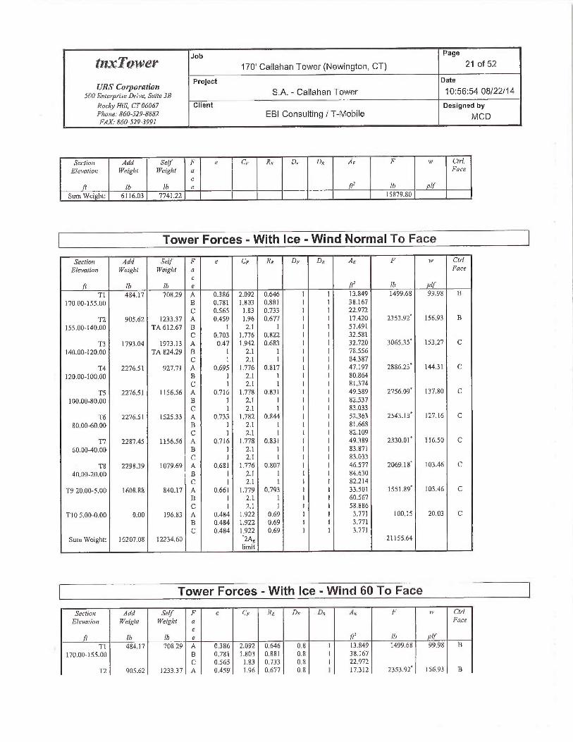
Job Page
~~x~~~~'~ 170' Callahan Tower (Newington, CT) 21 of 52
URS CospoY~tto~z Project Date
SOOEnte~priseDrive, st~rr~sa S.A. -Callahan Tower 10:56:54 08/22/14
Rocky Hill, CT 06067 Client Designed byPhone: 860-529-8882 EBI Consulting / T-MobileFA.X.• 8h0-529-3991
IVICD
Section Ada SeIJ F e CF RN DF DR .9E F u~ Ctrl.
Elevation WeigHt Weight a Face
c/t !6 lb e fi' !h !f
Sum Weight: 6116.03 7741.22 15879.80
Tower Forces -With Ice -Wind Normal 7o Face
Section Add Sel/' F e CF RR Df DR A~ F titi~ Cp•!
Elevation Weight Weight a Facec
(t Ib lb e rte !b jfTl 484.17 708.29 A 0366 2.092 0,646 I I 13.849 1499.68 99.98 A
170.00-]55.00 B 0,781 1.8D3 0.881 I I 3&167C 0.565 1.83 0.733 1 I 22.972
T2 45.62 123337 A 0.459 1.96 0.677 I I 11.420 2353.92 156.93 D
155.00-140.00 TA 612.67 B 1 2.] 1 1 I 57.491C 0.703 1.776 0.822 I I 32.581
T3 1793.04 1973.13 A 0.47 1.942 0.683 I I 32.720 306535 153.27 C
140.00-120.00 TA 824.29 B 1 2.1 1 I I 78.556C 1 2.1 I I I 84.387
T4 2276.51 927.71 A 0,695 1.776 0.817 l I 47.197 288G.23i 14431 C
120.00-100.00 B ] 2.1 1 I I 80.8b4C ] 2.1 1 I I 81374
TS 2276.51 1156.56 A 0.716 1.778 0.831 1 I 49389 2756.09' 137.80 C
100.00-80.00 B 1 2.1 1 1 I 82.537C 1 2.1 1 1 I 83.033
T6 2276.51 1525.33 A 0.733 1.782 0.844 I I 523b3 2543. ] 3' 127.16 C
80.00-60.00 B 1 2.1 1 I I 81.668C 1 2.1 1 1 I 82.109
T7 2287.=~5 1156.56 A 0.716 1.778 x.831 I I 49389 2330.01 ~ 116.50 C
60.00-40,00 B 1 2.1 1 I I 83.871C I 2.1 1 I I 83.033
T8 229834 1079.69 A 0.681 1,776 0.807 I I 46.577 2069.18' 103.46 C
40.00-20.00 B I 2.] 1 I I 84.630C I 2.1 1 I I 82.214
T9 20.00-5.00 1608.88 840.17 A 0.661 1.779 0.793 I I 33.501 1551.89 103.46 C'B I 2.1 1 I I 60.567C I 2.1 1 I f 58.886
T10 S.DO-0.00 0.40 196.3 A 0.4tS4 1.9'22 O.ti9 1 I 3.771 100.15 20.03 CB 0.484 1.922 0.69 1 I 3.771C 0.484 1.922 0,69 1 1 3.77]
Sum Weight: 16207.08 12234.60 ~2As 21155.64limit
Tower Forces -With Ice -Wind 60 To Face
Seciiai Add Se!/' F e C,: R,; D,- D„ AE h' ~v Ch'!.
Elevatio~r Weight Weight a Facec
j! lb Ih e ft' lh !j'
Tl 484.]7 708.29 A 0386 2,092 0.646 0.8 1 13.8=19 1499.68 99.98 B
170.00-155.00 B x.781 1.803 0.881 0,8 I 38.167C 0.565 1.83 0,733 0.8 I 22.972
T2 905.62 1233.37 A 0.459 1.96 0.677 0.8 1 17312 2353.92' 156.93 B

Job Page
~~~~'~~ 170' Callahan Tower (Newington, CT) 22 of 52
URS Corj~otafiott Project Date
SOQ Er~terpriseDrii~e, suu~ 3a S.A. -Callahan Tower 10:56:54 08!22/14
Roc19~Hiil, CT 06067 Client Designed byPhone: 860-529-SBRZ EBI Consulting / T-MobileFAX. 860-529-3991 M C D
Section Add Self F e C~ RH DF~ DR AE F ~+~ CU•!.Elevation Weigh! Weighl a Face
c
f !fi Ib e fi' fb if155.OQ-140.00 TA 612.67 B 1 2.1 1 D.8 1 57.458
C 0.703 1,776 0.822 0.8 I 31.994T3 1793.04 1973.13 A 4.47 1.942 0.683 0.8 I 27.263 3065.35 ] 53.27 C
140.00-12D.00 TA 824.29 B 1 2.1 1 0.8 1 75.023C ] 2.l 1 0.8 I 73.433
T4 2276.51 427.71 A O.b95 1.776 0.817 0.8 1 41.570 2886.23' 14431 C120.00-100.00 B 1 2.] I 0.8 ( 80280
C 1 2.1 1 U.8 I 73.574TS 2276.51 1156.56 A 0.716 1.778 0:831 0.8 I 43.656 2756.09 137.80 C
100.00-80.00 B 1 2.] I 0.8 I 81.918C 1 2.7 I 0.8 I 75.200
T6 2276.51 1525.33 A 0,733 1.782 0.844 0.8 1 44.094 2543.13 127.16 C80.00-60.00 B 1 2.1 1 0.8 1 78.724
C 1 2.1 I 0.8 I 71.958T7 2237.45 1156.56 A 0,716 1.778 0.831 0.8 I 43.656 233D.07~ 116.50 C
60.00-40.00 B I 2.1 I 0.8 I 83. ] 2lC I 2.1 1 0.8 I 75.200
T8 229839 1079.69 A 0.681 1.776 0:807 0.8 I 40.950 2069.18 103.46 C40.00-20.00 B I 2.] 1 0.8 I 83.774
C 1 2.1 1 0.8 I 74.414T9 20.00-5.00 1608.88 840.17 A 0.661 1.779 0.793 0.8 I 29.56 1551.89 103.4b B
B 1 2.l 1 0.8 I 59.967C 1 2.1 1 0.8 I 53.426
T10 5.00-0.00 0.00 196.83 A 0.484 1.922 0.69 0.8 I 3.547 4420 18.84 CB 0.484 1.922 0.69 0.8 I 3.547C 0.484 1.922 0.69 D.8 I 3.547
Sum Weight: 16207.08 12234.60 `2As 21149.69limit
Tower Farces -With Ice -Wind 90 To Face
Section Add Self F e Gs RR DF Dq AE F w CtrlElevation Weight WeigTtt a Face
ct !b Ih e jt- 1G ptJ'
Tl ~&d.17 70&.29 A U3~6 2,092 O.b46 U.$5 I 13.849 ]449.68 99.98 B170:00-155.00 B Q.78] 1.803 0,881 0,85 I 38.167
C Q.565 1,83 0.733 0.85 1 22.9727'2 905.62 1233.37 A 0.451 1.96 0.677 0,85 I 17.339 235392' 156.93 B
155.00-140.00 TA 612.67 B l 2.1 1 0.85 I 57.466C 0.703 1.776 0.822 0.85 I 32.141
T3 1793.04 1973,13 A 0.47 1.942 0.653 0.85 I 28.627 305535 153.27 L140.00-120.00 TA 824.29 B 1 2.1 1 0.85 I 75.906
C 1 2.1 1 0.85 I 76.171T4 2276.5] 927.71 A 0.695 1.776 0.817 0.85 I 42.977 ?886.23' 144.31 C
120.00-100.00 B l 2.1 1 0.85 I 8Q.426C 1 2.1 ] 0.85 I 75.524
TS 2276.51 ll56.56 A 0.715 L7'18 0.831 0.85 I 45.069 2756,09' 137.80 C100.00-80.00 B 1 2.1 1 x.85 I 82.D73
C 1 2.l ] 0.85 I 77.158T6 2276.51 1525.33 A 0.733 1.782 0.844 0.85 I 46.]67 2543.13 12716 C
80,00-60.00 B 1 21 I 0.85 I 79.460C 1 2.1 I 0.85 I 74.496
T7 2287.45 1156.56 A 0.716 1.778 0,831 0.85 I 45,089 2330.01 1!6.50 C60.00-40.00 B 1 2.1 I 0.85 I 83.308
C I 2.1 I 0,83 I 77.15R

Job Page
~~~~Qw~X 170' Callahan Tower (Newington, CT) 23 of 52
URS Co►po~'atiott. Project Date
SUO E~iterpl-ise Drive, Surt~ 3a S.A. -Callahan Tower 10:56:54 08/22/14
RocAj~ Hit/, CT 06067 Client Designed byPhone: 660-529-8882 EBI Consulting I T-Mobile MCDFAX 860-529-3991
Sectzon Add Sel/ F e C~ R,+ Dr~ De A~ F ia~ Ctrl
Elevation YYetght i3~eigh7 n Face
c(t !b Ih e ftz Ib !f
T8 229839 ]079.69 A 0.68] 1.776 0.807 0.85 1 42.357 2069.18' 103.46 C
40.00-20.00 B 1 2.1 1 0.85 I 83.988
C 1 2.1 1 0.85 I 76.364
T9 20.00-5.00 1608.88 840.17 A 0.661 1.779 0.793 0.85 I 30.547 1551.89' 103.46 L
B 1 2.1 I 0.85 I 60.117
C 1 2.l 1 O.BS 1 54.791
T10 5.00-0.00 OAU 196.83 A 0.484 1922 U.69 0.85 I 3.603 95.69 19.14 C
B 0.484 1.922 0.69 0.85 1 3.603
C O.A84 ].922 0.69 O.SS I 3.603
Sum Weighh 16207.08 ]2234.60 ~2As 2ll51.18
limit
Tower Forces -Service -Wind Normal To Face
Seclioit Add Self F e CF RR D,: DN AE F w Cirl
Elevation Weigh( Weight a Face
c/~ !b I6 e 1t`' lb If
Tl 191.43 378.16 A 0.266 2.389 0.606 I I 8.762 621.07 41.40 A
170.00-155.00 B 0.527 1.868 D.712 I I 20346
C 0362 2.145 0.637 I I 12.492
T2 362.94 826.95 A 0.306 2.2R 0.618 I I 10.461 931.44 62.10 B
155.00-140.00 TA 456.98 B 0.724 1.779 0.837 1 1 32.924
C 0.443 1.985 0.67 I I ] 6.286
T3 643.40 1250.39 A 034? 2.19 0.63 I I 25.062 1450.43 72.52 C
140.00-120.00 TA 682.09 B 0,757 1.79 0.862 I I 50380
C 0.78 1.802 0.88 I I 52.473
T4 853.00 496.70 A 0.453 1.969 0.675 f 1 22.095 1174.15 58.7] B
120.00-100.00 B 0.736 1.783 0.846 I I 45.OS I
C 0,725 ].78 0.838 I I 43.932
TS 853.00 686.65 A 0.479 1.929 0.687 I I 24,335 1177.76 58.89 fi
100,00-80.00 B 0.755 1,79 0.861 I 1 47.664
C 0.744 1.785 0.853 I 1 46.538
T6 853,00 865.11 A D.507 7.892 0.707 I I 29.347 116827 58.41 B
80.00-60.OU B 0.774 1.799 0.876 I I 50.534
C 0.764 1.794 U 868 1 I 49.534
T7 854.40 666.65 A 0.479 1.929 0.687 I I 24.335 101439 50.72 B
60.00-40.00 B 0.763 1.793 0.867 I I 48,465
C 0.744 1.785 0.853 I I 4b.536
TS 855.80 712.32 A 0.437 1.995 0.667 I I 21358 859.28 42,96 B
40.00-20.00 B 0.744 1,785 0.852 I I 46.434
C 0.716 1.778 0.832 I I 43.587
T9 20.00-5.00 599.06 559.79 A 0.426 2.0]4 0.663 I I 15.507 596.58 39.77 B
B 0.7]2 1.777 0.829 I I 32.385
C 0.686 1.776 0.8] I I 30.498
T10 S,UO-0.00 0.00 139.43 A 0377 2.112 0,612 I I 2.774 60.75 12.15 C
B 0.377 2.112 0.642 I I 2.774
C 0377 2.112 0.642 I I 2.774
Sum \~Veig1~C 6116.03 7741.22 9D54.12
Tower Forces -Service -Wind 60 To Face

Job Page
~I?1T01VL~f" 170' Callahan Tower (Newington, CT) 24 of 52
URS Corporation Project Date
SOOE~Tter~riseDrzve, Suite 3B S.A. -Callahan Tower 10:56:54 08/22/14
Rodg~Hill, CT 06067 Client Designed byPhone: 860-529-8882 EBI Consulting / T-MobilePAX' 860-529-3991
M C D
Sectiai ddd Self F e CF RN Dt Dx •9~ F w Ctrl.
F.levatiou Weig)d Weight a Face
cf [b Ih e ft' !h Ij
Tl 191.43 378.16 A 0.266 2389 0.606 0.8 1 8.762 621.07 41.40 B
170.00-]55.00 B 0.527 ].868 0.7]2 0.8 I 20346
C 0362 2.]45 0.637 0.8 1 12.492
T2 362.94 826.95 A 0.306 2.28 0.618 0.8 I 10353 929.81 61.94 B
155.00-140.UU TA 456.98 B 0.724 1.779 0.837 0.8 I 32.866
C 0.443 1.985 0.67 0.8 I ]6.185
T3 693.4D 1250.39 A 0342 2.19 0.63 0.8 I 20.050 1349.76 67.49 C
140.00-120.00 TA 682.09 B 0.757 1.79 0.862 0.8 I 46.645
C 0.78 1.802 0.88 0.8 I 48.831
T4 853.00 496.70 A 0.453 1.969 0.675 0.8 I 22.095 1174.15 58:71 B
12Q.00-100.00 B 0,736 1.783 0.846 0.6 I A5.051
C 0.725 1,78 0.835 0.8 I 43.932
TS 853.00 686.65 A 0.479 ].929 0.687 0.8 I 24.179 1175.22 58.76 B
100.40-80.00 B 0.755 1.79 0.861 0.8 I 47.561
C 0.744 1.785 0.853 0.8 I 46.432
T6 853.00 865.11 A 0.507 1.892 0.701 0.8 I 26.949 1117.8] 55.89 B
80.00-60.00 B 0.774 1.799 0.876 0.8 I 48351
C 0.764 1.794 0.868 0.8 I 47339
T7 854.40 686.6.5 A 0.479 1.929 0.687 0.8 I 24.179 1012.29 50.61 B
60.00-40.00 B 0.763 1.793 0.867 0.8 1 48364
C 0.744 1.785 0.853 0.8 I 46.432
T8 555.80 71232 A 0.437 1.995 0.667 0.8 I 21358 859.28 42.96 B
40.00-20.00 B 0.744 1.785 0.852 0.8 I 46.434
C 0.716 1.778 0.832 0.8 I 43.587
T9 20.00-5.00 599.06 559.79 A 0.426 2.014 0.663 0,8 1 15.507 59(1.58 39.71 B
B 0.712 1.777 0.829 0.8 I 32385
C 0.686 1.776 0.81 0.8 I 30.498
T10 5.00-0.00 0.00 139.43 A 0377 2.112 0.642 0.8 I 2.550 55.84 11.17 C
B 0377 2.112 0.642 0.8 I 2.550
C 0.377 2.] 12 0.642 0.8 I 2.550
Sum Weight: 611(.03 7741.22 8891.81
Tower Forces -Service -Wind 90 To Face
Section Add Selr F e CF RR D~.~ DR A~ F w Ctrl
Elevaliun Weight Weight u Face
L'
ft fb !b e (t' !U ylf
TI 191.43 378.16 A 0.266 2.389 0.606 0.85 1 8.762 621.07 41.40 B
170.00-155.00 B 0.527 1.868 0.712 0.85 l 20346
C 0.362 2.145 0.637 0.85 1 12.492
T2 362.94 826.95 A 0306 2.28 0.618 0.85 I 10.380 930.21 62.01 B
]55.00-140.00 TA 456,98 B 0.724 1,779 0.837 0.85 I 32.881
C 0.443 1.985 0.67 0.85 I ]6.210
T3 643.0 125039 A 0.342 2.19 0.63 O.SS 1 21.303 1374.93 68,75 C
140.00-120.00 TA 682.09 B 0.757 1.79 0,862 0.85 I 47.579
C 0.78 1.802 0.88 0.85 I 49.742
T4 853.00 496.70 A 0.453 1.969 0.675 0,85 I 22.095 1174.15 58.71 B
120.00-100.00 B 0.736 L,783 0.84b 0.85 I 45.051
C 0.725 1.78 D.838 0.85 I 43.932
TS 353.00 686.65 A 0.479 1.929 0.687 0.85 I 24.218 1175.66 58.79 B
100.00-80.00 B 0.755 1.79 0.861 0.85 f 47.587
C 0.744 L785 0.853 0.85 I 46.459
T6 853.00 SGS.] 1 A 0.507 1.892 0.70] 0.85 I 27.548 ] 130.42 56.52 It
50.00-00.00 B 0.774 1.799 0.876 0.85 1 48.897
C 0.764 1.794 0.868 0.85 I 47.888
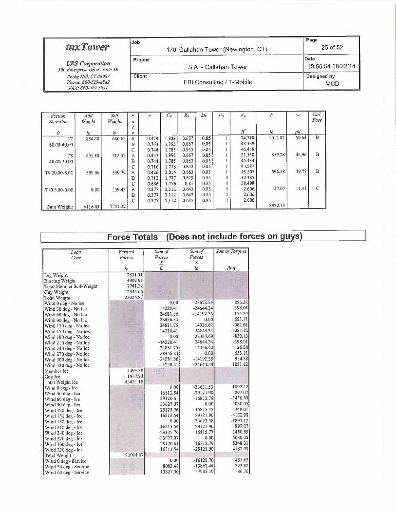
Job Page
~~~~~~~ 170' Callahan Tower (Newington, CT) 25 of 52
URS CoY]~oYatiott ~'roject Date
SOOEnter~riseDrive, Suite 3B S.A. -Callahan Tower 10:56:54 08/22/14
RocicpHill, CT 06067 Client Designed byPFione: 860-529-8882 EBI Consulting / T-Mobile MCDFAX.- 860-529-3991
Section Add Self F e Cs Rx DF DR~ AE F w Ctrl.
Elevatiat N~eight Weight n Face
c/t Ib lb e (' lh if
T7 854.40 686.65 A 0.479 1.929 0.687 0.85 I 24.218 1012.82 50.64 B
60.00-40.00 B 0.763 1.793 0,667 0.85 I 48389
C 0.744 1.785 0.853 0.85 I 46.459
T8 855.80 712,32 A 0.437 1.995 0.667 0.85 I 21358 859.28 42.96 B
40.00-20.00 B 0.744 1.785 0.852 0.85 I 46,434
C 0.716 1.778 0.832 0.85 I 43.587
T9 20.00-5.00 599.06 559.79 A 0,426 2.014 0.663 0.85 I 15.507 596.58 39.77 B
$ 0.712 1,777 0.829 0.85 I 32.385
C 0.686 ].776 0.81 0.85 I 30,498
T105.00-0.00 O.OD 139.43 A 0.377 2.112 0.642 0.85 1 2.606 57.07 1].41 C
B 0.377 2.712 0.642 0.85 I 2.606
C 0377 2.112 0.642 0.85 1 2.606
Sum Weight: 6116.03 7741.22 893239
Force Totals (Does not include fiorces on guys)
7 oad Vertical Suns o/' Suns of Sum of Torques
Case Farces Forces ForcesX Z
16 lb !6 lb-fit
L,eg Weight 2831.31
Bracing Weight 4909.91
Total Member Self-Weight 7741.22
Guy Weight 2444.66Total Weight 23024.87Wind 0 deg - No Ice 0.00 -28673.24 856.22
Wind 30 deg - No Ice 14228.41 -24644.34 398.01
Wind 60 deg - No Ice 24581.86 -119235 -154.24
Wind 90 deg - No Ice 28456.83 0.00 -653.11
Wind 120 deg - No Ice 24831,75 14336.62 -982.61
Wind 150 deg -No Ice 14228.41 2464434 -1051.12
Wind 180 deg-No Ice 0.00 28384,69 -830.13
Wind 210 deg - No Ice -14228.41 2464434 -398.01
Wind 240 deg -No Ice -24831.75 14336.62 12638
Wind 270 deg - No Ice -28456.83 0.00 653.11
1'Ui~td 300 deg - No Ice -24581.86 -14192.35 98438
1'Jind 330 deg - No Ice -14228.41 -24644.34 1051.12
Mchil~cr Ice .~:I'~38
Guy Ice 1937.94
'total Weight Ice -!3(I:? 1.18
1'Vinel 0 deg -Ice 0.00 -33631.53 1897.12
\Vind 30 deg -Ice 16813.54 -29121.90 -$97.07
Wind 60 deg -Ice 29120.61 -16812.79 -3ASU.89
Wind 90 deg -ice 33627,07 0.00 -5080,05
Wind 12fl deg -Ice 29125.76 16815.77 -5348.01
1~Jind I50 deg -ice 16813.54 29121.90 -4182,98
Wind 180 deg -Ice 0.00 33625.58 -1897.12
Wind 210 deg -Ice -16813.54 29121.90 897.07
Wind 240 deg -Ice -29125,76 16815.77 3 }50.89
Wind 270 deg -Ice -33627.07 0.00 5080.05
Wind 300 deg -Ice -29120.61 -16812.79 5348.01
Wind 330 deg-Ice -16813.54 -29]21.90 4182.98
Total Weight 23024.87 ' I
Wind 0 deg -Service 0.00 -16128.70 481.62
Wind 30 deg- Service 8003.48 -13862.44 223.88
Wind 60 deb- Service 13827.30 -7983.]9 -86.76

Job Page
tf'lX•T(,~ti1~EY" 170' Callahan Tower (Newington, CT) 26 of 52
UR5 Corporalion Project Date
SOOEntwprireDrive, Suite 3B S.A. -Callahan Tower 10:56:54 08/22/14
RncAj~Hi!/, CT 06067 Client Designed byPhone: 860-529-8882 EBI Consulting / T-MobileFAX.• 860-529-3991
M C D
Lead Vertical Sa m nr Suis of Spun o(Tw~qucr
Case forces Forces ForcesX Z
lb !h lh [h-fi
Wind 90 deb; -Service ~'. 16006.97 0.00 -36737
Wi~~d 120 deg -Service 13967.86 806435 -552.72
Wind 150 deg -Service - 8003.48 13662.4A -541.25
Wind 18Q deg -Service E 0.00 15966.39 -4G6.95
Wind 210 deg -Service -8003.48 13862.44 -223.88
Wind 240 deg -Service -13967.86 806435 71.09
Wind 270 deg -Service -16006.97 0.00 36737
Wind 300 deg -Service -1382730 -7983.19 553.71
Wind 330 de -Service -8003.48 -13862.44 591.25
Load Combinations
Conrb. Descripteai
No.
1 Dead Only2 Dead+Wind 0 deg - No Ice+Guy3 Dead+Wrnd 30 deg - No Ice+Guy
4 Dead+Wind 6(l deg - No Ice+Guy
5 Dead+Wind 90 deg - No Ice+Guy
6 Dead+Wind 120 deg - No Ice+Guy
7 Dead+Wind I50 deg - No Ice+Guy
8 Dead+Wind i 80 deg - No Ice+Guy
9 bead+Wind 210 deg - No Ice+Guy
10 Dead+Wind 240 deg - Nn Ice+Guy
11 Dead+Wind 270 deg - No Ice+Guy
12 Dead+Wind 300 deg - No Jee+Guy
13 Dead+Wind 330 deg - No Ice+Guy14 Dead+Ice+Temp+Guy
I S Dead+Wind 0 deg+Ice+Temp+Guy
16 Dead+Wind 30 deg+Ice+Temp+Guy
17 Dead+Wind 60 deg+Ice+Temp+Guy
18 Dead+Wind 90 deg+Ice+Temp+Guy
19 Dead+Wind l2Q deg+Ice+Temp+Guy20 Dead+Wind I50 deb+Ice+Temp+Guy
2l Dead+Wind l80 deg+Ice+Temp+Guy
22 Dead+Wind 2I0 deg+Ice+Temp+Guy
23 Dead+Wind 2~i0 deg+lce+Temp+Guy
2~ Dead+Wind 270 deb+Ice+Temp+Guy
25 Dead+Wind 300 deg+Ice+Temp+Guy
26 Dead+Wind 330 deg+Ice+Temp+Guy
27 Dead+Wind 0 deg- Service+Guy
28 Dead+\Wind 30 deg -Service+Guy
29 Dead+Wind 60 deg -Service+Guy
30 Dead+Wind 90 cieg -Service+Guy
31 Dead+Wind ]20 dcg-Service+Guy
32 Dead+Wind 150 deg- Service+Guy
33 Dead+Wind 180 deg -Service+Guy
34 Dead+Wind 210 deg - Service+Guy
35 Uettd+Wind 2~0 deg - Service+Guy
36 Dead+Wind 270deg-Service+Guy
37 Dead+Wind 300 deg - Savice~t~Guy
38 Deud+Wind 330 dug -Service+Gw

Job Page
tnrTo~vet" 170' Callahan Tower (Newington, CT) 27 of 52
URS Corpol'Rf.~on Project Date
SOOEnIerpriseDrive, S~~;re3B S.A. -Callahan Tower 10:56.54 08/22/14
Roc6j~fli/1, CT 06067 Client Designed byPhnne~ 860-529-8882 EBI Consulting / T-Mobile MCDFAX.•860-529-3991
Maximum Member Forces
Section Elevation C0137f7071H11I Cw~dilinn Gov, Force A9ajw•ffxis ~MinorAxis
No ft Tt/~e Load A9oment Mo~~tentCouch. Ib lb-/t Ih-/~
T1 I70 - 155 Leg Max Tension 4 13018.79 -3].42 1838
Max. Compression 19 -15420.49 -18.17 -1036
Max. Mx 24 8683.16 -408.43 -69.48
Max. My 21 10253.09 1328 446.8A
Max. Vy 18 1770.76 -35.42 8.21
Max. Vx 21 1926.71 -4.16 -34.65
Diagonal Max Tension 26 2212.97 0.00 0.00
Max. Compression 26 -2264.11 0.00 0.00
Max. Mx 19 1657.42 -12.98 0.07
Max. My 20 -1825.86 1.06 -4.91
Maa. Vy 19 8.49 -12.98 O.D7
Max. Vx 20 2.35 1.06 -4.91
Top Girt Max Tension 10 12.0 0.00 0.00
Max. Compression 21 -21.69 0.00 0.00
Max. Mx 14 -6.99 3.90 0.00
Max. My 18 -4.43 0.00 -0.00
Max. Vy ]4 -4.56 0.00 0.00
Max. Vx ] 8 -0.00 0,00 0.00
Bottom Gist Max Tension 2l 847.64 0.00 0.00
Max. Compression 6 -766.20 0.00 0.00
Max. Mx 14 Sb.66 3.90 0.00
Max. My 18 72.24 0.00 -0.00
Max. Vy 14 -4.56 0.00 0.00
Max. Vx 18 -0.00 0.00 0.00
T2 ]55 -140 Leg hoax Tension 17 15288.8] -631.71 375.70
Max. Compression ]5 -37950.44 1.24 673.90
Max. Mx 24 -10453.4] -7]7.94 133.09
Max. My 2] 15159.59 -2.95 -75334
Max. Vy 23 -3787.65 57937 -344.23
Max. Vx 15 -4713.00 1,24 673,90
Diagonal Max Tension 25 3354.71 0.00 0.00
Max. Compression 19 -4509.02 0.00 0.00
Mux. Mx IS 1511.94 -83.88 -5.24
Max. My ]8 -2430.07 8.12 -15,61
Max. Vy 15 43.77 -83,88 -5.24
Max. Vx 18 7.47 8.12 -15.61
Secondary Max Tension 17 803.12 0.00 0.00
HorizontalMax. Compression IS -657.32 0.0(1 0.00
Max. Mx 14 183.80 5.44 O.OU
Max. My 18 579.76 0.00 -0.00
Max. Vy 14 -637 0.00 0.00
Max. Vx 18 0.00 0.00 0.00
Top Girt Max Tensio» 14 61.12 0.00 0.00
Max. Compression 4 -2.88 o.ao 0.00
Max. Mx 14 57.29 3.90 0.00
Max, My 18 49.71 0.00 -0.00
Max. Vy 14 -4.56 0.00 0,00
Max. Vx 18 -0.00 0.00 0.00
Bottom Girt Max Tension 16 345.37 0.00 0.00
Max. Compression l 0.00 0.00 0.00
Max. Mx 14 224.13 3.90 0.00
Max. My 18 327.16 0.00 -0.00
Max. Vy 14 -4.56 0.00 0.00
Max. Vx 18 -0.00 O.UO 0.00
Guy A Bottom Te»sion 21 7862.02Top Tension 21 8039.11
Top Cable Vert 21 683]39

Job Page
~I~YT011'GY 170' Callahan Tower (Newington, CT) 28 of 52
URS Cot'pa~'ation Project Date
SO(1 Enie~pr•iseDrive, s~~tr~ 3B S.A. -Callahan Tower 10:56:54 08/22/14
Rncky Hilf, CT 06067 Client Designed byPhase:560-529-8882 EBI Consulting/T-Mobile MCDFAX.• 860-522-3991
Section Elevation Co~rrponertt Co~tdition Gmt Fovice Major Axis d~inot•Axls
No. ff Tjpe Loud h~nment h9wrien!
Top Cable Norm 21 4237.843'~p CaUle Tan 21 6.68Bot Gable Vert 21 -6429.12
Bot Gable Non» 21 4525.23Bat Cable Tau 21 7.17
Guy B Bottom Tension 25 7884.47Top Tension 25 805038
Top CaUle Vert 25 6703.03Top Cable Norm 25 445839Top Cable Tan 25 7.07Bot Cable Vert 25 -6314.29Bot CaUle Norm 25 4721.70Bot Cable Tan 25 6.16
Guy C Bottom Tension 17 7807.65Top Tension 17 7966.89
Top CaUle Veri 17 6523.16Top Cable Norm 17 4573.81Top Cable Tan ] 7 6.34Bof CaUle Vcrt l7 -614].83Bot Cable Norm l 7 4820.5 ]Bot Cable Tan 77 637
Top Guy Pull-Off Max Tension 17 3b30.68 0.00 O.ODMax. Compression 2 -2690.09 0.00 0.~0
Max. Mx 14 397.95 -6.57 0.00Max. My 18 250.05 0.00 0.00
Max, Vy ]4 7.68 0.00 0.00
Max. Vx 78 -0.00 Q.DO O,dO
Torque AtYn Top Max Tension 16 4178.72 0.00 D,00
Max. Compression 5 -1425.44 0.00 D,00
Max. Mx 21 -788.22 -24079.40 -0.00
Max. My 18 -124.29 -]4406.53 -0.00
Max. Vy 21 6930.29 -24079.40 -0.00
Max. Vx 18 -0.00 -14406.83 -0.00
T3 140 - 120 Leg Max Tension 21 36486.57 -593.43 3.91
Max. Compression ]5 -6234933 ]86.91 2.96
Max. Mac 21 20542,69 -1889.74 17.41
Max. My 20 -I 1365.12 -760.85 -216fi35
Max. Vy 23 -4693.72 1847.08 -15539Max. Vx 20 2154.72 -760.85 -216635
Diagonal Max Tension 24 5713.64 -113.47 -30,72
Max. C~mpressign 22 -5942A9 -77A3 -~G,19
Max. Mx 25 3200.83 15631 -0.15
Max. My ZO -4243.58 -0.20 -70..96Max. Vy 2S -78.45 15637 -0.15
Max. Vx 20 -33.80 0.00 0,00
Secondary Max Tension 2] 3234.67 Q.00 0.00
HorizontalMax. Compression 15 -1673.92 0.00 0.00
Max. Mx 14 X79.58 -6.79 0.00
Max. My 18 973.17 0.00 0.00
Max. Vy 1 ~ -7.94 (1.00 0.00Max. Vx l8 D.00 x,00 0.00
Top Girt Max Tension 23 1181.80 0.00 0.00Max. Compression 21 -42].96 0.00 0.00
Tvlax. Mx 14 137.95 -4.14 0.00
Max. My 18 186.54 0.00 0.00Max. Vy 14 4.84 D.QO 0.00Max. Vx 18 -0.00 0.00 0.00
Bottom Girt Max Tension 23 1279.0] 0.00 QAO
Max. Compression 8 -447.09 O.OQ O.OQMax. Mx 14 380.81 -4.75 0.00

Job Page
tn~1CT~)jUe1' 170' Callahan Tower (Newington, CT) 29 of 52
URS CoNpoi'ation Project Date
son E,u~rPr•ts~or~~ve, Su:te3B S.A. -Callahan Tower 10:56:54 08/22/'!4
Rock~~Hill, CT06~67 Client Designed byPharre; ~56~-529-888? EBI Consulting / T-Mobile MCDFAX.• 860-529-991
Section Elevation Con~yonentnJo fr r~~~
Guy A
T4 120 - 100
Guv B
Guy C
Torque Arm Top
Leg
Diagaial
Top Girl
Bottom Girt
TS 100 - 80 Leg
Cmidilion Gov Force A~ujorAxis dli~iorA.xisLoad Alouient A9onrentcoy»n_ rb ~b-n rb-r
Max. My 24 -?83,91 0.00 0.00Max. Vy 14 -5.56 0.00 0.00Max. Vx 24 0.00 0.00 0.00
Bottom Tension 21 20190.49Top Tension 21 20523.78
Top Cable Vert 21 16556.24Top Cable Norm 21 12129.16Top Cable Tan 2l 6.10Bot Cable Vetrt 2] -159303bBot CaU(e Norm 21 12404.81
- Bot Cable Tan 2l 8.42Bottom Tension 25 19832.16Top Tension 25 20141.41
Tep Cable Vett 25 15801.01Tap Cable Nonn 25 12490.] $Top CaUle Tan 25 6.74Bok Cablc Ver[ 25 -1520132BotCableNorm 25 12737,13Bot CaU]e Tan 25 7.Q3Bot[om Tension i7 19242.36Top Tension 17 19537.23
Top Cable Vert T7 1498132Top CaUle Norm 17 12540.46Top Cable Tan 17 6.05Bot Cabe Vert 17 -14396.20Bot Cable Nome 17 ] 2767.84Bot Cable Tan 17 7.1 ]Max Tension 2G 13364.10 -8881.58 D.00
Max Compression 20 -6316.10 0,00 0.00Max. Mx 21 -4496.58 -55729.97 0.00Max. My 2D 127.21 -54381.55 -0.00Max. Vy 21 15990.16 -55729.97 0.00Max, Vx 20 -0.00 -54381.55 -0.00
Max Tension 1 0.00 0.00 0.00Max. Compression l5 -36985.57 -10.73 -158.74
Max. Mx 24 -24775.02 -359.3] -92.24Max. My 21 -24582.12 20.09 387.50Max. Vy 18 -2792.25 -94.35 114.29Max. Vx 21 -3123.69 -3.81 -14.02
Max Tension l8 1269.10 0.00 Q.00Max. Compression 20 -179630 -10.79 -0.24
Max. Mx 22 -39238 -56.50 0.6bMax. My 22 -556.74 -0.55 234Max. Vy 22 29.1 S -56.50 0.66Max. Vx 22 1.1l 0,00 0.00
Max Tension 23 816.50 0.00 0.00Max. Compression ] 0.00 0.00 0.00
Ivfax. Mx 14 574.56 3.40 0.00Max. My 24 555.71 0.00 -0.00Max. Vy 14 -4.56 0.00 0.00Max. Vx 24 0.00 0.00 0.00
Max Tension 23 507,72 0.00 0.00Max. Compression 1 0.00 0.00 0.00
Max. Mx 14 355.71 3.90 0.00Max, My 19 392.65 6.00 0.00Max. Vy 14 -4.56 OAO 0.00Max. Vx ] 9 O.DO 0.00 0.00
Max Tension 1 0.00 0.00 0.00Max. Compression 22 -45134,60 -4.40 55.68
Max. Mx 18 -28092.48 -265.57 -123.53Max. My 15 -28188.45 ].57 304.04

Job Page
tj1~~T~wer 170' Callahan Tower (Newington, CT) 30 of 52
Project DateURS Co~~~oPrction
SOOEnlei~riseDrive,5uite3B S.A. -Callahan Tower 10:56:54 08/22/14
Rncbj~ Fli!/, CT 06067 Client Designed byPhase: Sb0-529-8882 EBI Consulting / T-Mobile MCDFAX.- 860-529-3991
Section Elevation Cnmpo~ien! Condition Gvu. Force AlajorAxis n~inorAzir
No. ,ft Type Load Monteni Mane~atCo~nh. Ih Ib-f lh-ft
Max. Vy 23 875.66 254.38 -121.72Max. Vx 15 987.72 132 290.60
Diagonal Max Tension 18 1056.11 0.00 0.00Max. Compression IS -139438 -4.72 -0.57
Max. Mx 22 -56.10 -40.77 0.43Max. My 23 -848.91 25.91 1.74Max. Vy 22 21.69 -40.77 0.43Max. Vx 23 -0.83 -25.91 1.74
Top Girt Max Tension 23 489.80 0.00 0.00Max. Compression 1 0.00 0.00 0.00
Max. Mx 14 363.53 3.9U 0.00Max. My 19 372.30 0.00 0.00Max. Vy 14 -4.56 0.00 0.00Max. Vx 19 0.00 0.0o O.QO
Bottom Girt Max Tension 23 91133 0.00 0.00Max. Compression 1 0.00 0.00 OAO
Max. Mx 17 406.86 3.90 0.00Max. My 20 601.07 0.00 0.00Max. Vy 17 -4.56 0.00 0.00Max. Vx 20 -0.00 0.00 0.00
Guy A Bottom Tension 21 7457.43Top Tension 21 7550.03
Top Cable Ved 21 5194.54Top Cable Nonn 21 5479.02Top Cable Tan 21 0.04Bot Cable Vert 21 -4955.4]Bot Cable Norm 2] 557290Bat Cable Tan 21 0.04
Guy B Bottom Tension 25 7217.68Top Tension 25 ?300.66
Top Cable Vert 25 4724,43Top Cable Nonn 25 5565.91Top Cable Tan 25 0.01Bot Cable Vert 25 -4500.69Bot Cable Nonn 25 56A2.57BoYCable Tan 25 0.01
Guy C Bottom Tension I7 7021..89Top Tension 17 7099.11
Top Cable Vert 17 4373.64Top Cable Norm 17 5591.847'op Cable Tan 17 0.06Bot Cable Vert ] 7 -4159.31Bot Cable Norm 17 5657.49Bot Cable Tan ] 7 0.66
Top Guy Pull-Off Max Tension 23 3609.45 D.~O O.ODMax. Compression 1 O.QO 0.00 0.00
Max. Mx 16 1711.13 10.77 0.00Max. My 20 33.88.08 0,~0 -0.00Max. Vy l6 12.60 0.00 0,00Max. Vx 20 -0.00 0.00 O.UO
T6 80 - 60 Leg Max Tension l 0.00 0,00 0.00Max. Compression 22 -46348.91 -376.41 56,32
Max. Mx 22 -4556833 -589,77 60.89Max. My 24 -38734.55 -5139 115.31Max. Vy 23 -1103.73 47.39 -1.42Max. Vx 24 480.77 5,77 -4.70
Diagonal Max Tension 22 269.43 0.00 0.00
Max. Compression 22 -1486.40 0.00 0.00Max. Mx 22 -1179.67 -36.93 -0.16Max. My 23 -1187.03 -0.29 ?.10Mux. Vy 22 19.86 -36.93 -0.16

Pa e
X12 t T011 ~G~l~ Job
170' Callahan Tower (Newington, CT) 9 31 of 52
URS CotJlolYttion Project Date
snnE,~~~,y,•;,reDrive,s~«:~38 S.A, -Callahan Tower 10;56:54 08/22/14
Rocln~Hill, CT 06067 Client Designed by ^
P/~oae: 860-529-8&82 EBI Consulting / T-Mobile MCDFAX.• 860-529-3991
Section Elevation Com~aten! Conditiwi Gov Force A9ajnrAxis Minor Axis
Na, ~t Tj~~e Logd Moment ATon~e~ttCanb. !b lh-jt Ib-f
Max. Vx 23 -1.00 -0.29 2.10
Secondary Max Tension 23 1077.07 O.OD 0.00
Hw•izontalMax. Compression 22 -802.79 0.00 0.00
Max. Mx 17 548.78 -6.57 0.00
Max. My 19 750.13 0.00 -0.00
Max. Vy 17 7.6B 0.~0 0.00
Max. Vx 19 0.00 0.00 0.00
Top Girt I~fax Tensiwi 18 200.42 0.00 SAO
Max. Compression 1 0.00 0.00 0.00
Max. Mx 17 197.65 3.90 O.QO
Max, My 20 184.46 0.00 0.00
Max. Vy 17 -4.5G 0.00 0.00
Max. Vx 20 -0.00 0.00 0.00
Bottom Girt Max Tension 21 254.19 0.00 0.00
Max. Compression I 0.00 0.00 0.00
Max. Mx 17 245.22 3.90 0.00
Max. My 19 197.63 0.00 0.00
Max. Vy 17 -4.56 0.00 0.00
Max. Vx 19 -0.00 0.00 0.00
T7 60 - 46 Leg Max Tension 1 0.00 0.00 0.00
Max. Compression 22 -49251.81 -219.08 10830
Max. Mx 24 -28079.01 374.48 82.68
Max. My 22 -41029.07 -10.80 -372.47Max. Vy 24 -484.24 292.05 -125.20
Max. Vx IS -1065.95 630 315.80
Di~~;onal Max Tension 22 119619 0.00 0,00
Max. Compressio» 22 -1536.71 0.00 0.00Max. Mx 22 123.01 -45.29 131
Max. My 23 -520.73 -2936 2.68
Max. Vy 22 23.85 -4529 1.3]
Max. Vx 23 -1:28 0.00 0.00
Top Girt Max Tension 23 938.96 0.00 0.00
Iviax. Compression ] O.OD 0.00 0.00
Max. Mac 17 416.08 3.90 0.00
Max. My 19 525.66 0.00 0.00
Max. Vy 17 -4.56 0.00 0.00
Max. Vx 19 -0.00 0.00 0.00
Bottom Girt Max Tension 20 878.98 0.00 0.06
Max. Compression 1 0.00 0.00 0.00Max. Mx 17 350,39 3.90 0.0~
Max. My 19 358.55 Q.00 0.00
Max. Vy 17 -4.56 0.00 0.00
Max. Vx ]9 -0.00 0.00 0,00
Guy A Bottom Tension 21 8295.6]Top Tension 21 8349.73
Top CaUle Vett 21 4013.55Top CableNa~n 21 7321.84Top Cable Tan 21 0.07Bot Cable Vert 21 -3852.47Bot Cable Norm 21 7346.81Bot Cable Tan 21 0.07
Guy B bottom Tension 25 8015.10Top Tension 25 8089.57
Top Cable Vert 25 3324.40TopCab]eNorm 25 737A.92Top Cable Tan 25 0.10Bot CaUle Vert 25 -3180.21Bot Cable Norm 25 7389.86Bot Cable Tan 25 0.10
Guy C Bottom Tension 17 7856.53

Job Page
~/aL~Uj'We'~" 170' Callahan Tower (Newington, CT) 32 of 52
URS Corpovation Project Date
SOOEnfe~~riseDrive. Suile3B S.A. -Callahan Tower 10:56:54 08/22/14
Roc1r~~Hill, CT 06067 Client Designed byPhone: 860-329-8882 Eei Consulting / T-Mobile MCDFitX.• 860-529-3991
Section E[evaliori Component Candi(ion Gay. Force Major A.xi.s A4inor•Axis
No. jt Tjye Load Moment A~o~nent
Ca~,b. !b !h ~ !b-f
Top Tension 17 7895.20Top Cable Vert 17 2861.78TopCaUleNonn ]7 7358.29Top Cable Tan 17 0.09Bot Cable Vert ] 7 -2726.27Bot Cable Nonn 17 736835
Bot Cable Tan 17 0.09Top Guy Pul]-Off Max Tension 23 460235 0.00 0.00
Max. Compression I 0.00 0.00 0.00
Max. Mx l7 1636.27 10.77 0.00
Max. My 19 2627.21 0.00 0.00
Max Vy 17 12.60 0.00 0.00
Max. Vx 19 0.00 0.00 O.UO
T8 40 - 2D Leg Max Tension 1 0.00 0.00 0.00
Max. Compression 22 -52566.04 496.94 67.55
Max. Mx 23 -48674.27 -58234 -2b.55
Max. My 23 -48443.92 -267.12 519.12
Max. Vy ] 8 -95037 19.05 -201.5
Max. Vx 15 890.23 -198.27 93.9]
Diagonal Max Tension 24 849.01 0.00 0.00
Max. Compression 18 -196430 0,00 0,00
Max. Mx 20 2.34 4.81 0.00
Max. My 19 -819.85 0.00 0.03
Max. Vy 20 -4.59 0.00 0,00
Max. Vx 19 -U.03 0.00 0.00
Horizontal Max Tension 22 920.10 0.00 0.00
Max. Compression 22 -910.47 0.00 0.00
Max. Mx 17 579.52 5.44 U.00
Max. My 19 83839 0.00 O.QO
Mex. Vy t 7 -6.37 0.00 0.00
Max. Vx 19 -0.00 0.00 0.00
Top Girc Max Tension l8 493.10 0.00 0.00
Max. Compression 25 -304.86 0.00 0.00
Max. Mx 17 20631 3.90 0.00
Max. My 19 -112,85 0.00 0.00
Max. Vy 17 -4.56 0.00 0.00
Max. Vx 19 -0.00 0.00 0.00
Bottom Girt Max Tension 23 465.69 0.00 0.00
Max. Compression 1 0.00 D.DO 0.00
Max. Mx L7 304.50 3.90 Q.00
Mux. My 19 213,0 0.00 0.00
Max. Vy 17 -4.56 0,00 0.00
Max. Vx ] 9 -0.00 0.00 0.00
T9 20 - 5 Leg Max Tension I 0.00 0.00 0.00
Max. Compression 22 -52516,62 -455.69 -42.53
Max. Mx 24 -45105.07 1900.41 854.82
Max. My 22 -45589.36 -47.37 -2105.47
Max. Vy 24 -8451.77 1900,41 854.82
Max. Vx 20 9732.54 -19.86 -2085.32
Diagonal Max Tension 20 1962.32 0.00 0.00
Max. Compression 20 -2794.12 0.00 O.QO
Max. Mx 20 196232 4.81 Q.00
Max. My 19 -223.69 0.00 0.03
Max. Vy 20 -4.59 0.00 0.00
Max. Vx 19 -0.03 0.00 0,00
Horizontal Max Tension 22 909.61 0.00 0.00
Max. Compression 22 -909.61 0.00 0.00
Mnx. Mx 17 651.13 5.44 0.00
Max. My ]9 838.03 O.OQ 0.00
Max. Vy 17 -637 O.UU 0,00
Max. Vx l9 -0.00 O.QO 0.00

Job - Page
~I~t ~OtiVG~~' 170' Callahan Tower (Newington, CT) 33 of 52
URS CoYpo►'nt~on Project Date
500EnlerNrise Drive, Sirite 3B S.A. -Callahan Tower 10:56:54 08/22/14
RockpHill, CT 0606; Client Designed byPhone: 860-529-8$82 EBI Consulting / T-Mobile MCDFAX.•860-529-3991
Sectiai Elevation Coin/~onent Conrtition Gov, Force A~ajarAxis MinorAris
No. fl Tjpe Load Momen! MonrenlCo~nh. IG (h-~ J8-ft_
T Top Girt Max Tension 18 527.19 0.00 0.00
Mnx. Compression 1 0.00 O.OU 0,00
Max. Mx 17 215.02 3.90 0.00Max. My 19 447.82 0.00 0.00
Max. Vy l7 -4.5G 0.00 0,00
Max. Vx 19 -0.00 0.00 0.00
Bottom Girl Max Tension 22 5799.16 0,00 0.00Max. Compression 1 0.00 0.00 0.00
Max, Mx 17 4625.43 7.72 0.00
Max. My 19 4156.60 0.00 0.00Max. Vy 17 -9.03 0.00 0.00
Max. Vx 19 -0.00 0.00 0.00
T10 5 - 0 Leg Max Tension 1 0.00 0.00 0.00
Max. Compression 22 -4899432 -27.14 -86.25
Max. Mx 22 -45935.75 2105.90 -44.30
Max. tvly 26 -41319.13 -123.28 -254.00Max. Vy 23 7644.19 -68.79 -44.53
Mux. Vx 25 -736.83 -1 ] 07.97 177.03
Top Giit Max Tension 23 5112.40 -10.27 032Max. Compression 1 0.00 0.00 0.00
Max. Mx 20 4486.61 -197.00 -4.18Max. My 19 4341.31 -188,10 -4.63
Max. Vy 20 101.93 -197.00 -4.18
Max. Vx ]9 3.72 -188.10 -4.G3
Bottom Girt Max Tension 1 0.00 0.00 0.00Max. Compression 20 -3970.26 -582.38 -3.80
Max. Mx 19 -3882.99 -58239 -3.95
Max. My I S -3744.11 -499.87 -4.38Max. Vy !9 3234.81 -582.39 -3.95Max. Vx 18 43.67 -499.87 -438
Mid Girt Max Tension 20 4,78 0.00 0.00
Max. Compression 22 -A0.09 0.00 0.00
Max. Mx ] 5 -1832 ].52 0,00Max. My 18 -338 O.QO 0.30Max. Vy 15 3.56 0.00 0.00Max. Vx 18 -0.70 0.00 0.00
Maximum Reactions
Location Condition Gav Vertical Horizonla(, X Horizo»tal, ZLoad lh Ih (h
CamhMast Max. Vert 23 ~ 125714.1 ] 1429.38 -796.40
Max. H, 2Q 123592.24 1624.97 5.12
Max. H~ 15 123443.89 -2.63 1642,78
Max.1v1, 1 0.00 5.52 4.40
Max. M, 1 O.QO S.S2 4.40
Max. Torsion 19 281.25 -1421.45 -786.44
Min. Verl I 79460.27 5.52 4.40
Min. H~ 18 12241936 -1627.24 14.70
Min. H~ 21 120423.96 1A.96 -1584,23
Min. Mx 1 0.00 5.52 4.40
Min. M,. 1 0.00 5.52 4.40
Min. Torsion 24 -397.53 1624.97 S.12
Guy C cei 107 Ll Max. Vert 10 -1108.47 -714.98 41235
Elev 10 ftAzimuth 240 deg
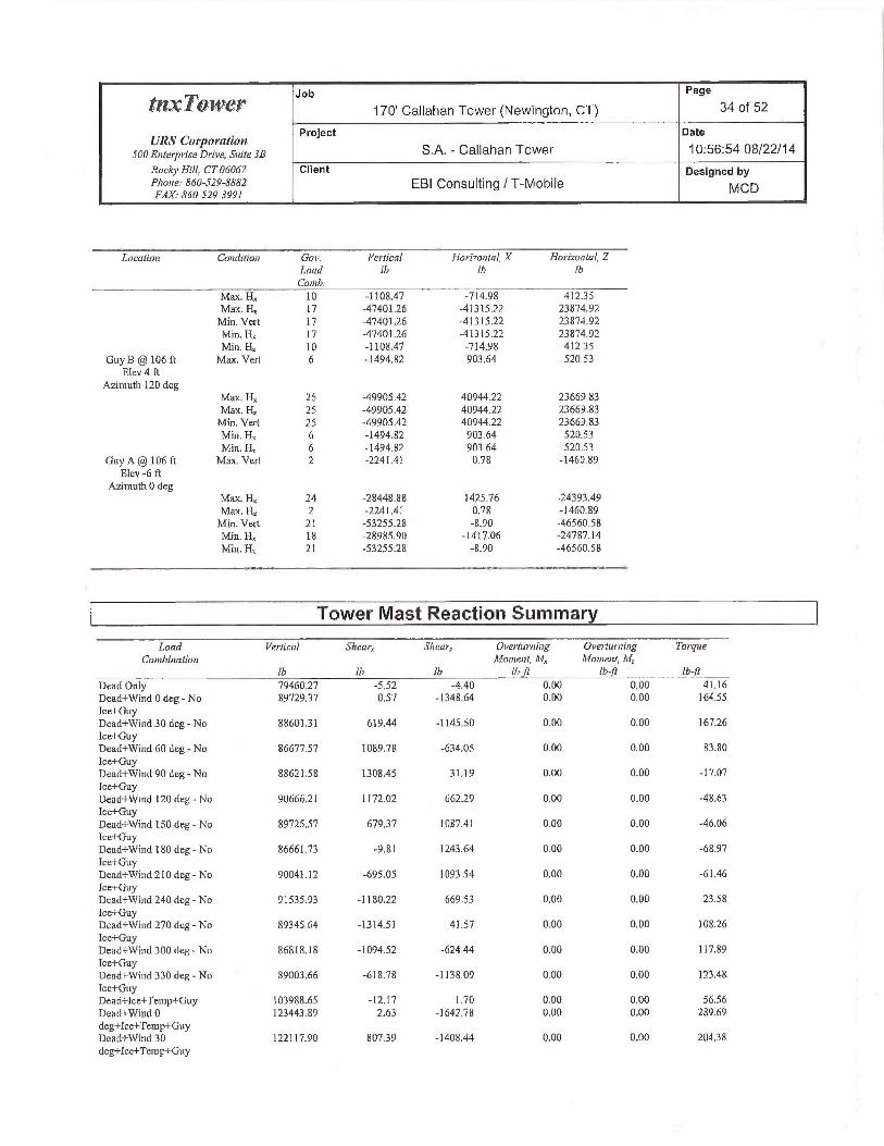
Job Page
~~~~~~ 170' Callahan Tower (Newington, CT) 34 of 52
URS Corporation Project Date
500 Enterprise Drine, su,r~ 3a S.A, -Callahan Tower 10:56:54 08/22/14
Rocky Hill, CT 06D6~ Client Designed byPho~~e: 860-529-8882 EBI Consulting /T-MobileFAX.• 860-329-3991
~1/~ C D
Location Co7tdifion Goi~. Vertical Hori~a~tal, X Ha-contai, Z
I,nad l6 Ib Ih
COl/1 ~,
Max. H„ 10 -118.47 ~ -714.98 41235Max. H~ 17 -47401.26 -41315.22 23874.y2
Min. Vert. 17 -4740].26 -41315.22 2387,92
Min. H. 17 -47401.26 -41315.22 23874.92Min. H~ 10 -1108.47 -714.98 41235
Guy B rt 106 ft Max. Vert 6 -1494,82 903.64 520.53Elev 4 ft
AzimutU 120 degMax. Hx 25 -49905.42 40944.22 23669.83Max. H~ 25 -49905.42 4094422 23669.83Min. Vert 25 -44905.42 40944.22 23669.83
Min. H, 6 -1494.82 903.64 520.53
Min. H~ 6 -1494.82 903.64 520.53Guy A @ lOb ft Max. Vert 2 -224].41 0.78 -1460.89
Elev -6 ftAzimuth 0 deg
Max. H,; 24 -28448.88 1425.76 -24393.49Max. Hz 2 -2241.41 0.78 -lAG0.89Min. Vert 21 -53255.28 -8.90 -46560,58Min. H, 18 -28985.90 -1417.06 -24787.]4Min. H, 21 -53255.28 -8.90 -46560.58
Tower Mast Reaction Summa
Load Vertical Shearrr Sheen; Ovet~furning Over-fttniiitg TargtteCou~binatiori Manenl, ~1~, ~l~ane~it, M
lb Ib lb Ih-Ji lb jt 16-It'
Dead On]y 79460.27 -5.52 -4,40 0.00 0.00 4].16
Dead+Wind 0 deg - No 89729.37 0.57 -1348.64 0.00 0,00 164.55Ice+GuyDead+Wind 30 deg - No 8860131 619.44 -1145.50 0.00 0.00 167.26
Ice-hGuyDead+Wind 60 deg-No 86677,57 1089.78 -634.05 0.00 0.00 83.80
Ice+GuyDead+Wind 90 deg-7~lo 88627.58 13Q8.45 31,19 0.00 0.00 -17.07
Ice+Guyllead+Wend 120 deg - No 90666.21 1172.02 titi2.29 0.00 0.00 -~F8.63
Ice+GuyDead+Wind 150 deg - No 89725.57 67937 1087.41 0.00 0.00 -46.06
Tce+GuyDead+Wind 180 deg-No 86661.73 -9.81 1243.64 0.00 0.00 -68.97
Ice+GuyDend+Wind 210 deg - No 90041.12 -695.05 ] 093.54 0.00 0.0 -61.46
Ice+GuyDead+Wind 240 deg - No 91535.93 -1180.22 669,53 0.00 0.00 23.58
Ice+GuyDead+Wind270deg-No 89345.64 -1314.5] 41.57 x,00 0.00 108.26
Ice+GuyDead+Wind 300 deg - No 86$ I8. ] 8 -1X94.52 -624 44 0.00 0.00 117.89
Ice+GuyDead+Wind 330 deg-No 89003.66 -618.78 -] 138.04 0.00 0.00 123.48
Ice+GuyDead+Ice+Temp+Guy ] 03988.65 -12.17 ] .7fl 0.00 0.00 56.56
Dead+Wind 0 123443.89 2.63 -1642.78 0.00 0.00 289.69
deg+Ice+Teivp+GuyDead+Wind 30 122117.90 807.39 -1408.44 0.00 0.00 204.38
deg+Ice+Temp+Guy

Job Page
fflrTnyve~" 170' Callahan Tower (Newington, CT) 35 of 52
URS Cot~oYation project Date
500 Enterprise Drive, s:~tr~ 3a S.A. -Callahan Tower 10:56:54 08/22/14
Rocbj~Hill, CT 06~fi7 Client Designed byPhase: 860-529-SRR2 EBI Consulting / T-Mobile MCDFAX.•86~-529-J991
Load Vertical Shear Sherry_ Overtairriing ~ ~ Over•hrrrzing Torque
Canhinatian A4nnaent, M, 11~onient, hIlh !b lh Ib-tt Ib-ft [b J7
Dead+Wind 60 1 19404.1 S 140832 -818.53 0.00 0.00 -?8.21
deg+lce+Temp+GuyDead+Wind 90 1221936 1627.24 -14.70 0.00 0.00 -253.46deg+Ioe+Temg+GuyDead+Wind 120 124746.48 1421.5 786.44 0,00 0.00 -281.25
deg+Ice+Temp+GuyDead+Wind ]50 124280.84 789.4? 1344.69 0.00 D.DO -210.01deg+Ice+Temp+GuyDead+Wind l80 12423.96 -1496 ]584.23 0;00 0.00 -1G4.23
deg+Ice+Temp+GuyDead+Wind 210 12469L.10 -807.48 1353.53 U.00 D.00 -40.70
deg+Ice+Tentp+GuyDead+Wind 240 125714.11 -142438 796.40 0.00 0.00 201,13deg+Tce+Temp+GuyDead+Wind27U 123592.24 -1624.97 -5,12 0.00 0.00 397.53deg+Ice+Temp+GuyDead+Wu~d300 119989.24 -]411.21 -801,53 O.OQ 0.00 38937deg+Icc+Tetnp+GuyDead+Wind 330 122869.64 -802.80 -1389.49 0.00 0.00 315.08deg+Ice+Temp+GuyAead+Wind 0 deg- 80747.50 -337 -744.38 0.00 0.00 101.8?Seivice+GuyDead+Wind 30 deg - 81073.48 353.33 -G3I.&2 0.00 0.00 102.82Seivicz+GuyDead+Wind 60 deg - 81223.69 616.22 -352.1 S 0.~0 O.QO b4.63
Service+GuyDead+Wind 90 deg - SU76b.29 723.88 1,58 0.00 0.~0 20.07
Service+GuyDead+Wind l20 deg - 80241.1 I 650.,06 370.51 0.00 D.00 4.78
Service+GuyDead+Wind 150 deg - 80365,27 368.60 519.18 0,00 0.60 -0.62Service+GuyDead+Wind ] 80 deg - 80538.34 -7.b4 708.33 0.00 0.~0 -7 832
Service+GuyDead+Wind 210 deg - 80302,48 -385.76 623.SU 0.00 0.00 -20.22Service+GuyDead+Wuid 240 deg - 80155.Q5 -667.52 377.60 0.00 0.00 ] 8.70Service+GuyDead+VVicid270 deg- 80606J6 -738,27 8.90 0.00 O.DO 64.41
Service+GuyTJead+Wind 300 deg - 81072.35 -625,20 -357.77 0.00 0.00 79.]9
Service+GuyDead+Wind 330 deg - 80978.69 -36033 -630,28 0.00 0.00 84.44Service+Guy
Solution Summary
Stuir of Apylied Forces SIf!]i O~RL[IL7iOg8
Load PX PY PZ PX PY PZ %Error•Con~G. lb !h th !h lh !h
0.00 -23024.15 -0,00 -0.26 23023.75 1.74 0.008%-1 1.01 -23 ] 15.39 -31483.08 10.95 23115.21 31481.47 0.004%15608.74 -?.2999.39 -2706427 -1560891 22999.25 27062.75 0.004°l26971.26 -22887.92 -15586.55 -2696935 22887.82 15586.45 O.~OS°!o31212.89 -23014.57 6,79 -31211.80 23014.44 -5.97 0.004%?7233.20 -23142.84 15750.49 -2723].76 23]42.63 -15749.50 0.004°la15627,63 -2303934 2708332 -15625.96 23039.]3 -27082.27 0.005%] 1,01 -22932.9? 3119~.5~ -12.03 22932.75 -31192.16 O.OQ7"/o

Job Page
tt'1•~I~TUtiVG~" 170' Callahan Tower (Newington, CT) 36 of 52
URS Co~~~a~ation Project Date
snoEr,r~ry~~~.s~ DT•~v~, s~~t~~ 3a S.A. -Callahan Tower 10:56:54 08/22/14
Roc~4~~ hill, CT 06067 Client Desighed byPhone: 860-529-8k82 EBI Consulting / T-Mobile MCDFAX: 85~-529-3991
Suet gjApplied Forces Sum of Reactian,sLoud PX PY PZ PX PY PZ % Er1•a•
Cnrnh Th !h lfi !h !6 IG
9 -15(08.79 m -Z30~38.93 27064.27 15607,64 23048.78 -2706359 0.003%
10 -27221.15 -2316Q39 75730.83 272I9.08 23160.10 -15729.48 D.006%
11 -31212.89 -23033.74 -6.79 31211.24 23033.54 7,98 0.005°l0
12 -2698330 -22905,47 -15606.21 26981.91 22905.41 15606.73 0.004%
13 -15627.63 -23008.97 -2708332 15627.65 23008.81 27081.55 0.005%
14 0.00 -43019.90 -0.00 -1.02 43019.84 2.62 0.007°/n
15 -21.62 -4320D.87 -39098.83 21:54 43200.48 39096.56 0,004%
16 19499.99 -42968.02 -33829.94 -19500.16 42967.82 33828.17 x.002%
17 33770.85 -42744.60 -19526.49 -33769.74 42744.55 19527.40 0.002%
]A 38989.24 -42999.86 12.40 -38988.20 42999.66 -12.05 0.002%
19 33798.85 -43258.49 19567.63 -33796.88 43258.05 -19566.27 0.004%
20 19536.47 -43051.76 3386733 -19534.y5 43051.47 -33866.48 0.003%
21 21.62 -42838.96 39092.88 23.02 42838.84 -39091.96 O.D03%
22 -19499.99 -43071.8] 33829.94 19498.D0 43071.43 -33828.88 0.004%
23 -33776.00 -43295.22 19529.46 33774.46 43294.87 -19528.46 O.D03°lo
24 -38989.24 -43039.96 -12.90 38987.72 43039.66 14.09 0.003%
25 -33793.7D -42781.33 -19564.65 33792.51 42781.29 19566.10 0.003%
26 -19536.47 -42988.07 -3386733 19536.57 42987.84 33865.80 0.003%
27 -6.19 -23075.47 -17709.23 61Q 23075.40 1770739 0.066°la
28 8779.94 -2310.22 -15223.65 -8780.06 23010,14 15220.1 0.010°/a
29 15171.33 -22947.52 -87&7.43 -15168.51 229A7.45 8766.29 O.D11%
30 17557.25 -23D18.76 3.82 -17555,93 Z301$.71 -2.72 x.006°/a
3l 15318.67 -23090.91 8859.65 -15317,91 23090.86 -8854.08 0.003°/a
32 8790.4 -23032.69 15234,37 -8789.73 23032.65 -15233.75 0.004°10
33 6.19 -22972.83 17546.92 -6.40 22972.76 -175A4.45 0.009%
34 -8774.94 -23038.09 15223.65 8778.72 23038.03 -15222.84 0.005%
35 -15311.90 -23100.78 8848.59 15310.40 23100.69 -8847.57 0.006%
36 -17557.25 -23024.54 -3.82 1755638 23029.51 4.49 0.004%
37 -15178.11 -2295739 -8778.50 15176.78 22957.36 8775.11 0.005°l0
38 -&790.54 -23015.61 -1523437 8790.28 23015.52 1523].25 0.071°10
(- Non-Linear ~anvergence Results
Loar! Converged? Nunther Di,splacernent Farce
Combination ofCpcles Talera~tce Tole~~ance--
1 Yes 10 0.00000001 Q_00006762
2 Yes t8 O.OD000OOI 0.00008322
3 Yes 17 0.00000001 0.00008736.
4 Yes 12 0.00000001 O.000Q82G4
5 Yes 18 O.00D00001 0.00007823
6 Yes 19 O.00Q]0724 0.00008380
7 Yes 18 0.00012980 0.000] 0576
8 Yes 13 O.QO~] 3650 0.00012388
4 Yes ]9 O.000OOODI 0.00007243
10 Yes ] 9 0.(~0~14393 0.0001 ] 131
11 Ycs l8 0.00014963 Q.000ll076
12 Yes 13 O.000OOODI 0.0000758813 Yes 17 0.00012666 0.0000981914 Yes 9 0.00000001 0.00007169
15 Yes 19 0.00012890 0.00009934
I6 Yes l9 0.00009304 0.00006779
I7 Yes 14 O.000D000] 0:00006556
18 Yes 20 0.00009288 0.00006628
19 Yes 20 0.00012943 0.00010158
20 Yes 20 O.0001013] 0.00008143
21 Yes 15 O.0001Q711 0.0000794]

Job Page
tnxTo~v~r" 170' Callahan Tower (Newington, CT) 37 of 52
URS Corporation project Date
snnE,~,~~~~~rs~D,~rv~,sui~e3a S.A. - Callahan Tower 10:56:54 08/22/14
RnclrnHill, CT 06067 Client Designed byPhone: 860-529-8881 EBI Consulting / T-Mobile MCDFAX.• 860-529-399/
22 Yes 20 0.00012970 0.00010299
23 Yes 21 0.00009730 0,00007725
24 Yes 20 0.00012464 O.000U9185
25 Yes 15 0.00014122 0.00009133
26 Yes 19 0.00009715 0.00007394
27 Yes 12 0.00000001 0.00010051
28 Yes 11 0.00000001 0.000121b2
29 Yes 10 0.00000001 0.00012407
30 Yes 12 O.000D0001 0.00009034
3] Yes 14 0.00000001 O.00006103
32 Yes 13 0.00000001 0.00006038
33 Yes 11 0.00000001 0.00009894
34 Yes 13 O.000OOOOI 0.00008890
35 Yes ]4 0.00000001 0.00011509
36 Yes 13 0.0000000] 0.00006655
37 Yes ll 0.00000001 0.00005938
38 Yes 11 0.0000000] 0.00013373
Maximum Tower Deflections -Service Wind
Secliori ElevatiotT Haz. Gov. Ti(t Tit~ist
No. Deflection Loadft iri Conch °
Tl 170-iS5 3.496 33 0.2809 0.0286
T2 155 - 110 2.659 33 0.2451 0.0277
T3 140 - 120 2.089 33 0.1260 0.0248
T4 120 - ] 00 1.915 33 0.0297 0.0224
TS 1 UO - 80 1.881 33 0.0240 0.0277
T6 80 - 60 1.754 33 0.0413 0.0350
T7 60-40 1.550 35 0.0777 0.0408
T8 40 - 20 1.220 35 D.0910 0.0494
T9 20 - 5 0,734 35 0.1473 0.0600
T10 5 - U 0.193 35 0.1785 0.0559
Critical Deflecfiions and Radius of Curvature -Service Wind
~'levatinn Appi[rYenattce Gou Deflection Till Twi.ct Radius nj
Load C~ovature
Jt Conch in f
175.00 DS4CO3F36U-D 8' Omni 33 3.496 02809 0.0286 28248
170.00 TTA432-83H-OIT 33 3.496 0.2809 0.0286 28?48
168.00 Pirod4'SideMountStandoff(1) 33 3378 0.2790 0.0285 28248
167.00 RFS SC2-W100BC 33 3320 0.2780 0.0285 28218
JG3.00 APXl6DWV-1GWVS 33 3.084 0.2723 D.0284 20177
152.33 Guy 33 2.53] 0.2289 0.0273 8321
146.00 VHLP2-180 33 2.269 0,]790 0.0261 6489
145.60 VI3LP800-11 33 2.255 0.1755 0.0260 6400
143.00 844H40TlIEXY 33 2.770 0.1525 0.0255 5903
141.50 (4) 844G65VTZASX w/Mount Pipe 33 2.127 0.1392 0.0251 5738
41.00 Pirod 12' T-Frame Sector Mount (1) 33 2 113 0. ] 347 0.0250 5713
132.44 Guy 33 1.465 0.0658 0.0235 8038
20.00 Pirod 12' T-Frame Sector Mount (1) 33 1.915 0.0291 0.0224 35554
90,00 Guy 33 1.833 0.0334 0.031(, 32369
50.00 Guv 35 1.4D0 0,0829 0.0443 39578

Pa e
~IZ.~: ~U11~LY Job 170' Callahan Tower (Newington, CT) g 38 of 52
URS Co1'p0YltiTon Project Date
SOOE~rlerpri,reDrire, Suite 3B S.A. -Callahan Tower 10:56:54 08/22/14
Rocbj~Hill, CT060h7 Client Designed by
Phone: 860-529-8882 EBI Consulting / T-Mobile MCDFAX. 860-529-3991
Maximum Tower Deflections -Design Wind
Section Elei~ntinn FIo~~. Gon. Tilt Twist
No De/%ction Loudrr ;,, co„~h.
Tl 170 - 155 $.7~3 20 D.5995 0.3386
T2 155 - 140 7.042 20 0.5339 03332
T3 140 - 120 5.889 23 0.2956 03044
T4 120 - 100 5.817 23 0.0890 0.2601
TS l00 - 80 6.194 23 0.0408 0.2537
TG 80 - 60 6.2] 4 23 0.0785 0.2498
T7 60 - 40 5.632 23 0.2218 0.2431
T8 40 - 20 4.457 23 03449 0.2423
T9 20 - 5 2,620 23 0.5381 0,2317
Tl 0 5 - 0 0.684 23 0.6354 0.1976
Critical Deflections and Radius of Curvature - Design Wind
Elevation Appw•tenance Gov. Deflection Tilt Twist Radius of
Load C:t~val~ire
Carib. in ° ft
175.00 DS4CO3F36U-D 8' Omni 20 8.703 0.5995 0,3386 16028
170.00 TTA432-83H-OlT 20 8.73 0.5995 0,3386 ]6028
168.00 Pirod 4' Side Mount Standof'F(]) 20 8.472 0.5965 03386 16028
IG7,00 RFS SC2-WLOOBC 20 8.357 0.5948 03386 16028
163.00 APXI6DWV-1G\~1N5 2U 7.900 0.5349 03381 11448
15233 Guy 20 6.781 0.5027 03298 4479
146.00 VHLP2-180 20 6.241 0.4045 0.3182 3]20
145.60 VHLP800-11 20 6,2] 1 03975 0,3174 3057
143.00 844H90T1 ] EXY 20 6.035 03508 03115 2715
141.50 (4) 844U65VTZASX w/Mount Pipe 23 5.952 0.3232 63080 2594
L41.00 Pirod 12' T-Frame Sector Mount (1) 23 5.930 0.3140 03068 2569
132.44 Guy 23 5.722 0.1623 0.2855 3378
120.00 Pirod ] 2' T-Frame Sector Mount (I) 23 5.817 0.0890 0.2601 9441
90.00 Guy 23 6 ~72 0.0567 0.2531 8776
50.00 Guy 23 5.117 0.2815 L1.2472 R~49
Bolt Design Data
Section Elevation Cnmprnienl Boll Bnl1 Sipe Nmnher A9axin:w~i Allowable Ratio Aflowohle Criteria
Nn Tj~r Grade O/' Load per• Loud Load Ratio
fi in Bol1.s Bnit lb Allort~ahle!h
Tl T 170 Leo A325N 0.7500 4 62.70 19438.60 0.003 ~ ~-333 Bolt Tension
Diagonal A325N OS000 I 2212.97 2523.00 ~ 877 ~ I ,333 Member Bearing
7'opGirt A325N 0.5000 I 2L69 4036,80 ~~ QQS ~ 1,333 MemUerIIearin~
Bottom Gilt A325N 0.5000 1 847 64 2523.00 0.336 Y ~ 333 Member Bearing
T2 155 Leg A325N 0.7500 4 3254.96 19413.30 ~ ~ ~g ~ 1333 Bolt Tension
Diagonal A325N 0.5000 I 4509.0?. 412334 x,044 Y ~-333 BoItS6ear
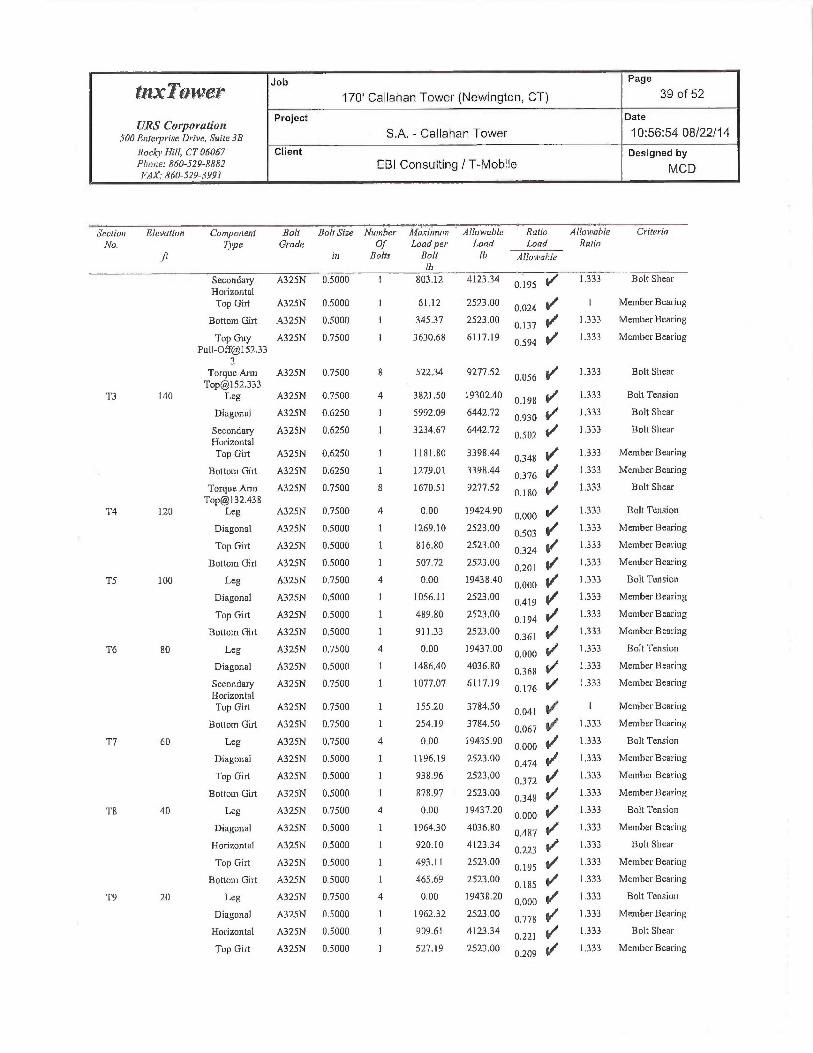
Job Page
~~~~~~~~ 170' Callahan Tower (Newington, CT) 39 of 52
URS Corporation Project Date
SOOF,nterpriseDrive,Suite3B S.A. -Callahan Tower 10:56:54 08/22!14
Rock~~Flill, CT 06067 Client Designed byPFaone: &6Q-529-8882 EBI Consulting / T-Mobile MCDFAX.- 860-529-3991
..,,,.,Sectia~ Glevatior~ Ca~npone~~i Boh Bolt Size Number h7aziniuu~ Al1oN~able Ratia Alloi~mhle CriteriaNn. Tjpe Grade Of Load per Lnad Load Ratio
ft in Bolts Bolt tb 9(lotvahle/h
Secondary A325N O.S000 1 803.12 4123.34 0.195 ~
1333 Bolt ShearHorizontalTop Girt A325N 0.5000 1 61.12 2523.00 ~ X24 ~ 1 Member Bearing
Bottom Girt A325N 0.5000 I 345.37 2523.00 ~~ 37 ~ ] 333 Member Bearing
Top Guy A325N 0.750Q 1 3630.68 6117.19 1333 Member Bearing0.594 ✓~
Pull-Off@I 52.333 ,/
Torque Ann A325N 475 0 8 52234 4z7~•Sz 0.056 1r
1.333 Bolt [email protected]
T3 lA0 Leg A325N ~.75Q0 4 3821.50 14302.40 ~ 198 ~ 1333 Solt Tension
Diagonal A325N 0.6250 1 5992.09 6442.72 0.930 ~
1333 Bolt Shear
Secondary A325N 0.6250 1 3234.67 6442.72 0.502 i~
1.333 Boh SheazHorizontalTop Girt A325N 0.6250 1 1181.80 3398.44 ~ 3¢g ~ 1,333 Member Bearing
Bottom Girt A325N 0.6250 1 ]279.01 3398.44 ~ 376 ~I 1.333 MemberBearin~
Torque Arm A325N 0.7500 $ 1670.51 9277.52 0.180 V
1.333 Bolt [email protected] -/
T4 120 Leg A325N 0,7500 4 0.00 19424.90 0:000 Y
1333 Bolt Tension
Diagonal A325N 0.>000 1 1269.10 2523.00 0.503 ~
1333 Member Bearing
Top Girt A325N 0.5000 1 816.80 2523.00 0.324 ~
1.333 MemberBeariug
Bottom Girt A325N 0.5000 1 507.72 2523.00 OZ~~ 4f 1333 Member Bearing
TS 100 Leg A325N 0.7500 4 0.00. 19438.40 0.000 ~ ~ •333 Bolt Tension
Diagonal A325N 0.5000 1 1056.11 2523.00 0.419 ~
1333 Member Bearing
Top Girt A325N 0,5000 1 489.80 2523.00 0.194 ~
1.333 Member Searing
Bottom Girt A32SN 0,5000 1 9] 133 2523.00 0.361 ~
1333 Member Bearing
T6 80 Leg A325N 0,7500 4 0.00 19437.00 0,000 ~ ~ •333 Bolt Tension
Diagonal A325N 0.5000 1 1486,40 4036.80 0368 ~
1.333 Member Bearing
Secondary A32~N 0.7500 1 1077.07 6117.19 ~ 176 ~ 1.333 Member BearingHorizontalTop Girt A325N 0.7500 1 15520 3784.50
0,041 ~;~ ~ MemUerSearing
Botiom Girt A325N 0.7500 1 254,19 3784.50 0.067 4~ 1333 MemUerBearing
T7 60 I.eg A325N 0.7500 4 0.00 19435.90 0.000 ~
1.333 Bolt Tension
Diagonal A325N 0.5000 1 1]96.19 2523.00 ~~74 ~ ].333 Member Bearing
Top Girt A325N 0.5000 ] 438.96 2523.00 ~ 372 ~ 1.333 Member Bearing
Bottom Girt A325N O.S000 1 878.97 2523.00 0.348 Y
1.333 Member Bearing
TB 4D Leg A325N 0.7500 4 0.00 ]9437.20 0.000 ~
1333 Bolt Tension
Diagonal A325N 0.5000 1 196430 4036.80 ~ 4S7 ~ 1333 Member Bearing
Horizontal A325N x.5000 1 920.10 412334 Q z23 Y 1.333 Bolt Shear
Top Girt A325N 0.5000 ] 493.11 2523.00 Q 195 ~ 1333 MemUer Bearing
Bpttom Girt A325N 0.5000 1 X65.69 2523.00 ~ ~~5 ~ 1333 Member Searing
T9 ZO Leg A325N Q.75~0 4 0.00 1943820 0.000 i~ 1.333 Bolt Tension
Diagonal A325N 0.5000 I 1962.32 2523.00 0778 'f 1333 Member Bearing
Horizontal A325N 0.5000 1 99.61 4123.34 p 22~ ~ 1333 Bolt Shear
Top Girt A325N U3000 I 527.19 2523.00 p 209 ~ 1333 MemUer Bearing

Job Page
tM~:TpI'VG'~" 170' Callahan Tower (Newington, CT) 40 of 52
UR5 Corporation Project Date
SDOEnter~ri.reDr•iv~, st«r~3B S.A. -Callahan Tower 10:56:54 08/22/14
Roc~i~ Hill, CT Ob067 Client Designed byPkare: 86(1-.i29-8882 EBI Consulting / T-Mobile MCbFAX.~R60-529-3991
Section Elevation C;nmponenl Bolt Boh Sipe Muxher A~uxim~nir A!lm~~able Ratio Allai~~ahle CriteriaNn. Tipe Grade Of Lnadper• Load Loud Rutio
fi in Bolts Bnit !h Allma~nh/e!h
Bottom Gin A490N 0,5000 1 5799.16 5497.79 1.055
1333 Bolt Shear
Tl0 5 Leg A325N 0,7500 4 0.00 19057.80 0.000 Y
~•a~3 BoltTe~ision
Guy Design Data
Seclinn Elevation Size h~itinl Breaking Actual ARoiatnfile Reyi~ir-ed ~lclitalNn Tension Load T T„ S.F. S.F.
~r fh !h Ih !h
T2 152.33 (A) 1i2 EI35 2690.00 26900.04 8039.11 ]3450.00 2.000 3.346
(567)152,33 (A) 1/2 EHS ~690.D0 2690.04 7962.53 13450.00 2.000
3.378(568)
152.33 (B) l/2 EH5 2690.00 26904(14 7780.78 13450.00 2.000 3.457
(563)]5233 (B) 1/2 EHS 2G90.D0 2G900.~4 8050.38 13450,00 2.000
3.341(564)
152.33 (C) 1/2 EHS 2690.00 26900,04 79E+6.89 13450.00 2.000 337C>
(556)15233 (L) ]/2 LFIS 2690.00 26900.04 7763.89 13450.00 2.000
3.4b5(557)
T3 132.44 (A) 7/8 EHS 797D.00 79G99.84 20523.80 39850.00 z•~~~ 3.883
(574) ~/132.44 (A) 7/8 EHS 7970.00 79699,84 20252.30 39850,00 2.000
3,933 ~/(580) ,,f
132.44 (B) 7/8 EHS 7)70.00 79649,84 19382.30 39R50.00 2,000 4.112 ~`
(575) ~/~132,44 (B) 7/8 NHS 7970.00 79699.84 20141.0 39850.D0 2.000
3.957 ~"(576)
132.44 (C) 7/8 EHS 7970.OD 79699.84 19537.20 39850.00 2.000 4X79(S71)
7 32.44 (C) 7/8 EHS 7970.00 79699.84 1901 U.70 39850.00 2.000 4 ~ ~~ ~+"'(572)
TS 90,OQ (A) 7116 EAS 2080.Q0 20800.Q2 7550.03 10400.00 2A00 ~ 75$(5$5)
90.00 (B) (584) 7/] 6 EHS 208D.00 20800.02 7300.66 10400.00 Z•~~~ Z,g49
90,00 (C) (583) 7/16 EHS 2080.00 20800.02 7099,1 1 10400.00 ?.000 Z g30
T7 50.00 (A) 7/16 EHS 2080.00 20800,02 8.149.73 10400.00 2.000 Z 491
(588)SO.OD (B) (587) 7/16 EHS 2Q80.00 20800.02 8089.57 10400.00 2.000
2,571 ~'/50,00 (C) (586) 7/16 EHS 2080.00 20800,02 7895,20 10400.00 ~•~~~ 2,635 ~/
Compression Checks
Leg Design Data (Com~aression)

Job Page
~~~~~~ 170' Callahan Tower (Newington, CT) 41 of 52
URS Corporation. Project Date
SOOEnleipriseDrivc,s,«r~3a S.A. -Callahan Tower 10:56:54 08/22/14
Rocl9~ Hill, CT 06067 Client Designed byPFrone: 860-529-RS82 EB1 Consulting / T-Mobile MCDFAX 860-529-3991
Sectiav Elevatiwi Si_=e L L„ KUr' Mast F -1 Actual Allow. Ratioeta Stability, P P„ P
ft ft fi Lidex ksi in' !h lb P~
Tl l70 - I55 ROHM 2 STD 15.00 2.42 36.8 1.00 26.267 1.0745 -15421.00 28224.70 0.546
K=1.00
T2 I55 -14fl ROH1V 2 STD 15.00 7.21 18.4 1.00 28.464 1.0745 -37950.40 30585.10 1241K=1.00 ~'°
T3 140 - 120 ROHM 2 STD w/ 1" 2Q.00 1.22 23.6 0.99 27.563 1.8578 -6234930 51207.20 L218
Solid Rod K=1.00
T4 12D -100 ROHN 2 STD 20.OD 2.44- 37.2 1.OD 26.224 1.0745 -36985.60 28178.50 1,313K=1,00
TS i DO - 80 ROHM 2.5 STD 20.00 2.44 30.9 1.00 27.Q44 1.7040 -45139.60 46084.60 0.979K=1.00
T6 80 - 60 ROIII~T 2 STD w/ 20.00 1.22 19.4 0.97 27.638 1.8149 -46348.90 5016030 0.924
1 /3rd pipe K=1.00
T7 6D - 40 ROHN 2.5 5TD 2U.00 2.44 30.9 0.98 26.537 1.7040 -49251.80 45220.10 1.089K=1.00 ~/
T8 40 - 20 ROHN 2.5 5TD 2~.0~ 2.44 30.9 0.98 26.561 1.7040 -52566.00 45262.10 1.161K=1,00
T9 20 - 5 ROHN 2.5 STD 15:00 2.42 30.6 0.98 26.564 1.7040 -52516.60 45265,50 1.160
K=1.00
T10 5 - 0 ROHN 2.5 STD 5.38 2.42 30.6 0.97 26.289 1.7040 -37300.90 44797.00 Q.833`K=1,00
DL controls
Diagonal Design Data (Compression)
Sectror~ Elei~afios Size L L„ Kl/r F„ A Actual R//ow. Ratio
No, P 1',. Pfj /i ft ksi iii' lb lb p~
T] 170- 155 P1.SxIGGA 4.19 ~ 1.97 363 19,476 03356 -2264,11 6536.80 0.346K=1.00 ~ f
T2 155 - 140 ROHM 1.5 STD 4.19 1.97 38.0 19.346 0.7995 -4509.02 15465.90 0.292K=1.d0
T3 140-120 L13/4x13/4x]/4 4.20 1.98 69.5 16.477 0.8125 -5992.09 ]3388.00 0.448K=1.00
T4 120-J00 P1.5x16GA 4.20 ].98 36.4 19.468 03356 -1796.30 6534.11 0.275K=].00
TS 100-80 P1.5x16GA 4.2D 1.95 36.0 ]9.504 D.3356 -139438 654b.18 0.213K=1.00
T6 8U-60 P1.5x16GA 4.2D 1.96 36.2 ]9.488 03356 -1A86.40 6540.78 0.227K=1.00 ~/
T7 60-40 PI.Sx16GA 4.20 ].95 36.0 19.504 03356 -1536.7] 6546.18 0.235K=1.00
T8 ~0 - 20 P1.Sx1GGA 4.20 3,9] 71.9 1b.229 03356 -1964.30 5447.03 0361K=1.00 y~
T9 20 - 5 P1.5x16GA 4.19 3.89 71.7 16.25] 0.3356 -2794. ] 2 5454.32 0.512K=1.00
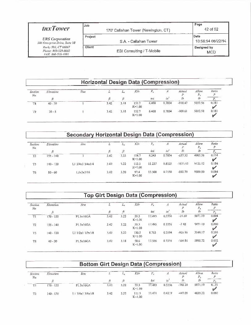
Pa e
t11xTa~~es~ Job 170' Callahan Tower (Newington, CT) g 42 of 52
URS Co~1lorr~tiott Project Date
snn E„r~,~~rs~Dr;,~~, s:,~r~ 3a S.A. -Callahan Tower 10:56:54 08/22/14
RncFj~Hi!!, CTOb~67 Client Designed byPr~~~~~: ~~n-szs-s~~z EBI Consulting / T-Mobile MCDFAX.' 8fi0-52?-3991
Horizontal Design Qata (Compression
S'ecliuit Eleuotion Si-c L L„ Kl/t• F„ A Actual A!/aty, Ralio
Nn. p p~~ pIt ft /t ksl iu' IG ifi P,~
T8 40 - 20 I 3.42 3.18 ] 52.7 6,408 0,7854 -910.47 5032.58 Q.181K=1.00 ~,r~`
T9 20 - 5 1 3.42 3.18 I52.7 6.408 Q.7854 -909.61 5032.58 0.187K=1.00
__ _.-
Secondary Horizontal Design Data (Compression
Section E(evafio~i Size L L„ Klh F„ A Actual Alloiac Ratio
Nn. j' f'~ }'Jt ft ksi in' lh lh p
T2 15.5 - l4~ 1 3.42 3.22 154.7 fi,243 D.7854 -65732 A903.26 0.134K=1.00
T3 740 - ]20 Ll 3/4x] 3/4x1/4 3.42 3.22 113.3 11.227 0.8125 -] 67392 9122.12 0.184~ K=1.00 ~/
T6 SD - 60 L2x2x3/l6 3.A2 3.20 97.4 13.300 0.7150 -802.79 9509.50 0.0&4K=] .00
Top Girt Design Data (Compression)
Secliori E/evalion S~~e L L„ Klh• F„ A Actua! Allow Ratio
No P pR PIt Ti ft ksi in' lh Ih p,
Tl 170-155 P1.5x1CGA 3.42 3.Z2 593 77.493 0.335G -21.69 58~1J9 0.004
K=1.00
T2 155 - 140 A1,5x16GA 3.42 322 59,3 17.49 03356 -7 RS SR71 19 0,000K=1.00 ~✓
T3 140- 120 Ll I/2x] i/2x1/8 3.42 3.22 130.5 6.763 0.3594 -921.96 3149.17 0,293K=1..00
T8 40-20 P1.Sxl6GA 3.42 3.18 58.6 17.566 0.356 -304.86 5395.72 0,05?K= l .00 ~f
Bottom Girt Design Data (Compression)
S~ctim~ Etei~crtion Si=e L L„ ~ K1Ir F„ A Aefun7 ALlori~. Ratio
Nn. P P„ P
/I Jt ft ksi ins !h !h p~
`T] 170-155 PI.SxIGGA 3.42 3.?2 59.3 17,493 0.3356 -766.20 5671.19 0.131K-1.0~ ~,s+
'T3 140- 120 LI 31Ax1 3!4x1/8 3.42 3.22 111.3 11.471 0.42]9 -447.09 483922 0.092K=1.00

Job Page
t12~1~T014JC'i" 170' Callahan Tower (Newington, CT) 43 of 52
URS Cor^pni'[ttio7t Project date
snnE,lr~,v,~rs~D,~;v~, 3i~ite3B S.A. -Callahan Tower 10:56:54 08/22/14
Rocij~Hi/l, CT 06067 Client Designed byPhone: 860-519-8882 EBI Consulting / T-Mobile MCDFAX.~860-519-3991
Section Elevation Srze L L„ KI/r F„ A ArUtal Allow Ratio
Aln. P P„ Pf~ J} ft ksi ur' lb !h P~
- -
T10 5 - 0 3x 1 /4 0.17 0,00 0.0 21.600 0.7500 -3265.17 16200.Q0 0.202'
K=1.00 ~,,1~'
" DL conh~ols
Mid Girt Design Data (Compression)~.Y..,,..~...,m~,.,..._.~~ ,,~~,
Section Elevation Srae /.. L„ K!/r F„ ; i Aclua/ f1llow. Ratio
No. P P.. P
/2 ft fr Asi in' (fi !h p~
7'10 5 - 0 3x l/A 1.71 1.47 244.5 2.498 0.7500 -40.09 1873.56 0.021
K=1.00 ~/
KL/R > 200 (C) - 555
Top Guy Pull-Off Design Data (Compression)
Section Elevation Size L L„ Klh• F„ A Actual Allow. Ratio
No P P„ P
J~ ft ft ksi rn1 lh Ib p~
T2 155 - l40 L2x2x3/l6 3.42 3.22 98.1 13.213 D.7150 -2666.59 9446.97 0.282
K=1.00
TS 100 - 80 4x3/8 3.42 3.1 S 352.6 21.600 1.5000 0.00 7 802.16 0.000
K=1.00
T7 60 - 40 4x3/8 3.42 3.18 35?.G 21.600 1.5000 0.00 1802.16 0.000
K=1.00
DL controls
Top Guy Pull-Off Bending Design Data
Sectiai Elevation Sipe Actual Actita! Alloii~ Ratio Acll~a! Aclua! Allnw. Ratio
Nn. M f,~ Fns /~~ 1~~y day Fnr .Ina.
/1 Ih-/t ksi ksi p,,, !h./i ksi ksi F,,r
T2 155 -140 L2x2x3/16 -4.64 -OJ73 23.7G0 0.007 -4,64 -0337 23.760 0.0]4
TS ] 00 - 80 4x3/8 10.77 -0, ] 29 27.000 0.005 0.00 0,000 27.000 0.000
T7 60 - 40 4x3/8 10.77 -0.129 27.000 0.005 -0.00 -0.000 27.000 0.000
Top Guy Pull-Off Interaction Design Data

Job Page
fl2YT01~VE,'Y 170' Callahan Tower (Newington, CT) 44 of 52
IIXS Corporation Project Date
500E~~te~yriseDrive, s~~ri~ 3s S.A. -Callahan Tower 10:56:54 08/22!14
Rnchj~Flill, CT 06067 Client Designed byPhase: $60-5?9-R882 EBI Consulting I T-MobileFAX. 860-?19-399/
MCD
Secliar Elevation 3i.e Ratio Ratio Rafio C~nrh Allow. Cr•iferin~,----
Nv. P fhr Ih~- St1•ers Strers
l P„ l~r„ r'i,,, Ratio Rata
T2 155- 14a L2x2x3!]6 0.282 0.007 0.014 03Q4 1333 fIl-3
YTS 100 - 80 4x318 0.000 0.005 0.000 ~ X05. ~ L000
H7-3
T7 (0 - 40 4x318 O.QOD 0.005 0.000 0.005 Y" ~ •000 Hl-3 M~
} DL controls
Torque-Arm Top Design Data
Secfiou Elei~atiat Si_>e L L„ h!h' F„ .9 .9ctual Allaw. Ratio
No P P„ P
fl ~t ft ksi in' I6 Ib P.,
T2 155 - 140 (558) Cl2x20.7 3.50 3.40 105..3 12.299 G.0900 -904.31 74898.00 0.012K=1.00
T2 155 - 140 (559) C12x20.7 3.50 3.40 1053 12.299 6.0900 -687.01 74898.00 0.009K=1.OD
T2 155 - 140 (565) C12x20.7 3.50 3.40 105.3 12.299 G.Q900 -62532 74898.00 0.008K=1.00
T2 155 - 140 (566) C12x20.7 3.50 3.40 105.3 12.249 G.U900 -72].83 74898.00 0.010K=1.D0
T2 155 - 140 (569) 012x20.7 3.50 3.40 105.3 ] 2.299 6A900 -902.10 74898.00 0.012IC=1.00
T2 155 - 140 (570) 012x20.7 3.50 3.40 105.3 12.299 6,0900 -788.29 74898.00 D.O11K=] .00
T3 140 - 120 (573) 012x20.7 w! 8"x318"plate 3,50 3,40 61.6 17:271 4.0900 -4239.96 156997.00 0,027K=1.00
T3 140 - 120 (574) 012x20.7 w/ S"~c3/S"plate 3.50 3.40 61,6 17.271 9.0900 -4261.23 156997.00 0.027K=1.00
T3 140 - 120 (577) 012x20,7 wi $"x3/8" plate 3.50 3.40 6.1.6 17.271 9.0900 -3824.25 156997.00 0.024K=1.00
T3 140 - 120 (578) 012x20.7 w/ 8°x3(8" plate 3.SD 3,40 61.6 17.271 9,Q900 -3790.26 156997.00 0.024x=~.00
T3 1~0 - 120 (581) 012x20.7 w/ 8"x3/8" plate 3.50 3.40 61.6 17.271 9.0900 -4484.24 156997.00 0,029K=1.00
T3 140 - 120 (582) 012x20.7 w/ 8"x3lS"plate 3.SU 3.4U GL.G 17271 9.0900 -4496.76 15ti497,00 0,029K=] .00
Torque-Arm Top Bending Design Data
Secliou Elevatia~i Sire Act~m7 Acrirn! Allow Ratia Acival AGual Allman Ra1in
rro. nor ~n~ F..., t~_, ~~~ f,,. r,,. f„•/t Ih-f Asi kri For lh;fl ksi ksi Pn>•
T2 I55 - ]40 (558) 012x20.7 -23038.7 -]2.859 27.600 0.95 -0.00 -0.000 2],600 OA00S
T2 155 - 140 (559) 012x20.7 -2474.& -13.437 21.600 0.622 -0.00 -0.000 21.600 0.0003
T2 155-140(565) 012x20.7 3469.5 -13.099 2L6D0 0.606 0.00 -x.000 ?1.600 0.0008
T. l 55 - 140 (566) 012x20.7 -23015.5 -12.846 21.C~Q 0.595 -0.00 -0.000 21.600 0.0000
T2 155 - 140 (569) 012x20.7 -23493.4 -13.113 21.600 0.607 0.00 -0,000 21.600 0,000

Pa e
~')2.~T~awef~ Job 170' Callahan Tower (Newington, CT) 9 45 of 52
URS CoYporation Project Date
snoEnre~yrts~D,•~u~, s„u~~a S.A. -Callahan Tower 10:56.54 08/22/14
Rocbj~Hili, CT (16067 Client Designed pyPh~~f~: ~6n-sz9-8s~z EBI Consulting / T-Mobile MCDFAX. 860-519-3991
Section Elevaliat Size AchsaJ Actual Allnw. Ratio .Aciunl Acrt~rnt ,41loi++, Ra{tio
NO. /~~x .fhc Fhs {hz /~~~ ./tCY Fhy /Ar
jt lh fJ kri ksi Fh~ 1G-ft ksi Asi Fhy
T2 I55 - 140 (570) C12x20J -24079.4 -13.440 21.600 Q.622 -0.00 -0.000 21.G00 U.D00
2T3 140 - ]20 (573) C12x20.7 w/ S"x3/8" plate -50317:3 -24.985 2I,600 1.757 -0,00 -0.000 21.600 0.000
3T3 14Q - 120 (574) Cl2x20,7 w(8"x318" plate -557 73 -27.662 21.600 1,281 -D.00 -0.000 21.600 O.00D
3T3 140 - 120 (577) C12x2Q.7 w/ S"x3/8"plate -52627.4 -26.132 21.600 1.210 O.QO -0,000 21.600 0.000
2T3 140 - 120 (578) C 12x20.7 w/ 8"x3/8" plate -50301.5 -24.977 21.600 1. ] 56 -0,00 -0.000 21.600 O.D00
8T3 140- ]2D (581) C12x20.7 w/ 8"x3/8"plate -52663.9 -26.150 2].600 1211 O.OD -0.000 21.600 O.00D
0T3 140 - 120 (582) C12x20.7 w/ 8"x3/8"plate -55730,0 -27.673 2L600 1.281 O.QO -0.000 21.6U0 0.000
0
[~ Torque-arm Top Interaction Desigw~ Data
Section Elevation Size Rafio Ratio Ratin Comb Alloia~, C~•iter•ia
No, P frR fn„ Stress Stressft p„ /:h~ r~~; Ratio Ratio
T2 155 - 140 (558) Cl2x20.7 0.0]2 0.595 0,000 0.607 ~ •3~3 Hl-3 J
T2 155 - 140 (559) C12x20.7 0.009 0.622 0.000 0.631 1.333 H]-3
T2 155 - ]40 (565) Cl2x20.7 0.008 0.606 O.ODO Q.615 1333 H ~ ~ ~/
T2 155 - ] 40 (566) C12x20.7 0.010 0.595 0.000 0.604 1.333 HI-3
T2 155 - 140 (369) C12x20.'7 0.012 0.607 0.000 O.b19 1333 Hl-3
T2 155 - 140 (570) C12x20.7 0.011 0.622 0.000 0.633 L333 H~ 3
T3 140 - ]20 (573) C12~c20.7 w/ 8"x3(8" plate 0.027 1.157 O.000 1.181 1.333 H 1-3
T3 140 - 120 (574) C12x20.7 w/ 8"x3/8"plate 0.027 1.281 0.000 1.308 ] 333 H 1-3 1~
T3 140 - 120 (577) C12x20.7 w/ 8"x3/8" plate 0.024 1210 0.000 1X34 1,333 Hl-3
T3 140 - 120 (578) C12x20.7 w/ S"x3/8" plate 0.024 1,156 0.000 1.181 ~~~33 H1-3
T3 140 - 120 (581) C12x20.7 w/ 8"x3/R"plate 0.029 1.211 0.000 1.I2~39 1.333 I31-3
VT3 140 - 120 (582) C12x20.7 ~~,~/ 8"x318"plate OA29 1.281 0.000 1310 1.333 ~~~ 3
V
-- _ _ _.
~~Tension Checks

Job Page
~/ZxTc~~t~er 170' Callahan Tower (Newington, CT) 46 of 52
Project DateURS Corporation
S0~ Erfferp~•i.se Dr~ivc, Suite 3B S.A. -Callahan Tower 10:56:54 08/22/14
RacAj~Hitl, CT 06067 Client Designed byPharte.~ 860-529-5882 EBI Consulting / T-Mobile MCDF,4X. 8G0-529-3991
Leg. Design Data Tension)
Secliwi Elevniian Si=e L L„ KUr F„ A .dcfi~a! Allow. Ratio
Nn P P„ P
. f/ ft jf kci ins lh th P..
Tl 170 - 155 ROHM 2 STD 15.00 2.42 36.8 30. 00 1.0745 13 18.80 32235.9O 0.404~,"'
T2 155 - 140 ROHM 2 S'TD 15..00 1.21 18.4 30.~~0 1.0745 152&8.80 32235.90 0I.4~74
rT3 140-120 ROHN2STbw/1"Solid 20.00 ],22 23.6 30.000 ],8578 3b486.60 55734.00 0.655
Rod
Diagonal Design Data (Tension
Seriiori Elcration Size L L„ Klh• F„ ;1 AcEital AlloHc Ratio
No. P Pu P
ft Il rt ksi i~~' (h fh Yr~
Tl 17Q-155 P1.5x16GA 4.19 1.97 363 21.6Q0 03356 2212.97 7249,72 0305
T2 155 -140 ROHN ].S STD 4.19 1.97 38.E 21.600 0.7495 3354.71 17268.30 0.194
T3 l40 - 120 LI 3!4x1 3/4x1/4 4.20 1.98 44,9 29.000 0.4688 5713.64 13593.80 0-.4f20
YT4 ]20 -100 P1.Sx16GA 4.20 1.98 36.4 21.600 03356 1269.10 7249,72 0.175
Y
TS l00 - SO P1.Sx16GA 4.20 J.45 36.0 21.600 0.335C 1056.] 1 7249,72 0-.1}46
4+~T6 80-60 P1.5x16GA 4.20 ].96 36.2 21.60Q Q3356 269.43 7249.72 0.037
T7 60-40 PI.Sx]6GA 4,20 ].95 36.0 2].600 03356 1146.19 7249.72 0.165
Y`t8 40 - 2D P1.Sx16GA 4.20 39l 719 21.600 0.3356 849.01 7249.72 0.717
T9 20-5 P1.Sx1GGA 4.19 3,89 71.7 21.600 03356 196232 7249.72 0.27]
Horizontal Design Data (Tension)
Section Elevation Sipe I, I.,, KI/r F„ .9 Actua! Allof~~. RcuiaN~ P P~ P
~p J[ ~t kci iu~ th !h p~
T8 40 - 20 I 3.42 3.1 S 152.7 21.600 0,7854 920.10 16964.60 0.054
T9 20 - 5 1 3.42 3.J 8 152.7 2].600 0.7854 909.61 16964.60 0.054

Pa e
tnxTo~ve~" Job 170' Callahan Tower (Newington, CT) 9 47 of 52
URS CorP~rati~n Project Date
.i00EnleryrtseDrive, s,~tt~ja S.A. -Callahan Tower 10:56:54 08/22J14
Roc~j~Hill, crn~n~s~ Client Designed byPho,~~: sbn-sz9-~s~sRz EBI Consulting / T-Mobile MCDFAX,- 86(1-529-3991
Seconds Horizontal Design Data Tension)~__ ~.__~_._~~ ,.. e~..,.._.
Section Elevation Si_e f. C.,, KI/r F„ d Actual Alloia. Ratio
Nn P P„ A
ft ,%t ft ksi in' lh Ih p~
T2 155 - 140 1 3.=12 3.22 154.7 21.600 0.7854 803.12 1 6964.60 0.047
T3 i40 - 120 Ll 314x1 3/4x114 3.42 322 73.] 29.000 0,4688 3234.67 ] 3593.80 0238
T6 80 - 60 L 2x2x3/1 C 3.42 3.20 62.2 29.000 0.4132 1077.07 11482.90 0.090
Top Girt Design Data (Tension
Section Elevation SEze L L„ KUr F .f Actunl Allow. Ratio
Nn. j' t'« PJl T i~ ksi its' !h Ib P..
Tl 170 - 155 P1,Sx16GA 3.42 3.22 54.3 21.6Q0 0.3356 12.40 7249.72 QOQ2
7'2 155 - l40 P1.Sx]6GA 3.42 3.22 593 21.G0~ 03356 61.12 7249.72 O.00S~
T3 140 -120 Ll ]/2x1 1!2x1/8 3.42 3.22 83.1 29.000 0.1992 ] 181.80 577734 0.205
T4 120-100 P1.Sx16GA 3.42 3.22 59.3 21,60Q 03356 816.80 7249.72 0.113
TS ]00-80 P1.SxI6GA 3.42 3.18 58.6 21,600 03356 489.80 7249.72 0,068
T6 80 - 60 P1.Sx16GA 3.42 320 S89 21.600 03356 155.20 7249.72 0.021
T7 60-40 PI.Sx16GA 3.42 3,18 58.6 21,600 0.3356 938.46 7249.72 0.130
T8 40-20 P1.Sx1GGA 3.42 3.18 58.6 2L6~0 03356 493.11 7249.72 O.OG8
T9 20-5 P1.Sx1GGA 3.42 3.18 58.6 21.600 0.3356 527.19 7249.72 0.073
T10 5 - 0 3x]/4 3.25 3.01 500.4 21,600 0.7500 3899.98 16200.00 0.241
UR > 500 ('I') -X48
DL C011tTO~S
Bottom Girt Design Data (Tension
Sectiat Elevafin~t Sipe L L„ Xl/r f%„ A Actual Atlo~• Hutia
ND P P„ P/i ft fi ksi m' rh th P..
T] 170-155 P1.SxIGGA 3.42 3.22 59.3 21,600 0.3356 847.64 7249.72 0.117
T2 155-]40 PLSxIbGA 3.42 3.27 593 21.6D0 0.3356 34537 7249.72 Q0~38

Job Page
t/'l.\ Tf114~E'j" 170' Callahan Tower (Newington, CT) 48 of 52
Project DateURS Corporation
snn E~r~,-P,~rs~ p,-;v~, st,vL 3a S.A. -Callahan Tower 10:56:54 08/22/14
Rnc,~j~Hil(, CT(J6067 Client Designed byPhnne: ~s~o-sz~-x~~z EBI Consulting / T-Mobile MCDFAX: X460-529-3991
Section Elevatioif Size L L„ KI/r F„ :i ,Actual Allo~~. Ratio
Nn. f' P~~ Pf .fj r~ I;si iv1 !h Ih Pn
_ ... - _ Y'
T3 ]4U- 120 Ll 3/~xl 3/4x1/8 3.42 3.22 70.9 29.000 0.2461 1279.01 7136.7? 0.179
T4 120 - 100 P1.Sx1fiGA 3.42 3.22 593 21.600 0335fi 507.72 7249.7? 0,070
T5 100-80 PI.Sx16GA 3.42 3.18 58.6 21.600 0:3356 9]1,33 7249.72 OJ26
T6 80 - GO P1.Sxl6GA 3.42 3.20 58,9 21.600 0335b 25G.19 7249.7? 0.035
T7 GO -40 P1.Sxl6GA 3.42 3.18 58.6 21.600 03356 878.97 7249.7? 0.12]
TS 40-20 P1.5x16GA 3.42 3.18 58.6 21.600 03356 465.69 7249.72 0,064
T9 20 - 5 ROHN 1.5 SCH XS (Extra 3.42 3.18 63.1 21,600 1.0681 5799.1( 23071.90 0.251
Strong)
Mid Girt Qesign Data (Tension)
~Seciion Elevation 5iae L ~ L„ Kl/r F,, d rlcittal Allow. Ratio
No P P~ P
fi fr ft ksi rn' th ~b ra
T10 5 - 0 3x1/A 1.7] 1.47 244.5 21.600 0.7500 4.78 16200.00 0.000
Top Guy Puli-Off Design Data ~Tension~
Sect[on El~valion 5!>e L L„ K7h• F~~ tl i4ctuol dhow. Ratia
Nn P P„ Prt ft ft ksi in' !b (h h..
T2 155 - Idl1 L2x2x3(16 3,42 3.22 ti2.7 21.600 0.715Q 3630.68 J 54A4,OQ 0.235
TS 100-80 4x3/8 3.42 3.18 352.b 27.GQ0 1,5000 3609.45 32400,00 0.171
T7 60-40 4~c3/8 3.42 3,18 352.6 21.600 I.50~0 4602.35 324p0.00 0.142
Top Guy Pull-Off Bending Design Data
Sectiai Elevation Sine Actisal Actual A!lo~v. Xrnio Actemf Acttraf Allow. Ratio
Nn ~~r 1i~.. F'a. ln.~ n~i• fn.. Fi~~ fayft rr~,f kse ksi Fh,. Ih-f F.ri kri Fr.,.
-.,T.,.~,.--_ . ~.._,W..,_,.~,......_ _ - --T2 155 - 140 L2x2x1/16 -4.64 0,173 23.760 0.1707 -464 0.340 23.760 0.014
TS 100 - 80 4x3/8 10.77 0.129 27.000 o,00s -o,o0 0.000 ?7.000 0.000
T7 60 - 4Q 4x3/8 10.77 0.129 27.000 0.005 -0.00 0.000 27.000 U.000

Job Page
tn~~; Tn1VLp 170' Callahan Tower (Newington, CT) 49 of 52
URS Cot~otat[ort Project Date
SOOEi~tetpriseDr~ivc,Suite3B S.A. -Callahan Tower 10:56:54 08/22/14
Rnrb~~Hill, CTOh067 Client Designed byPhone: R60-529.8881 EBI Consulting / T-Mobile MCQFAX.•860-529-3991
To Guy Pull-Off Interaction Design Data
_~~~~«~o; .,.,,.., ~-Elevation Si=e Raiio Ralin Ratio Cnnih. Allow. Cri~erio
~Vo P /h~ fn~~ Stress SJ~rss, fit 1',, Fi, F~_ Rutio Ralin -
T2 155-140 L2x2x3/16 0.235 0.007 0.0]4 0.257 1.333 II2-11/'~
TS 100 - 80 0.x3/8 0,111 0.005 D.000 0.116 1333 H2-1
T7 60-40 4x3/8 U.142 0.005 0.000 0.147 1333 H~ ~ }f
Torque-Arm Top Design Data
Section EJevatfon Size L L„ Klh~ F„ :J Acemf Allmv. Ratio
Nn. P P~ Pl ft ft ksi in' lh !h ry..
T2 155 -140 (558) C12x20.7 3.50 3.40 51.1 21.600 6.0900 43.83 131544.00 0.000
T2 155 -140 (559) C]2x2Q.7 3.50 3.40 51,1 ?1.600 6.0900 504.7D 131544.00 0.004
'I'2 155 - 140 (565) C12x20.7 3.50 3.40 51.1 21.600 6.0900 477.28 131544.00 0.004
T2 155 - ]40 (56G) C12x20.7 3.50 3.40 51.1 21.600 6.0900 298.10 131544.00 0.002
T2 155 - l40 (569) C12x20.7 3.50 3.40 SI.I 21.600 6,0900 75.09 131544.00 0.001
T2 1 SS - ] 40 (570) Cl2x20.7 3.50 3.40 51.1 21.600 6.0900 347.29 131544.00 0.003
T3 140-120(573) C12x20.7 w/8"x3/8"place 3.50 3.40 G1.6 21.6U0 9.0900 164,70 196344.00 0.001
'f3 140 - 120 (574) C]2x20.7 w/ 6"x3/8"plate 3,50 3.40 61.6 21.600 9.0900 127.21 196344.00 0.001
T3 140 - ]20 {577) C12x2~.7 w18"~c3/8"plate 3.50 3.40 61.6 21.600 9.0900 295.]9 146344.00 0.002
T3 140 -120 (578} C] 2x20.7 w18"x3/8"plate 3.50 3.40 61.6 21.600 9.0900 143.45 196344.00 0.001
T3 140 - 120 (581) C12x20.7 w/ 8"x3/8"plate 3.50 3.40 61.6 2].600 9.0900 64.17 196344.OD 0.000
T3 14U - 120 (582) C12x20.7 w/ 8"x3/8" plate 3.50 3.40 61.6 21.600 9.0900 5022.01 196344.00 0,026
Torque-Arm Top Bending Design Data
Seclio~i Elevation Sine Acfual Ach~al Alloiv Ratio Aetuo! Actua! Allo~~. Ratio
No. A~~ f-.< For T,r n'fy .fir Fay ~n~,
ft lh-/i kri ksi p,, lb f[ ksi ksi Fh,.
T2 155 - 140 (558) 012x20.7 -21531.6 12.018 21.600 0.556 0.00 0.000 27,000 0.000
7
'I'2 155 - 140 (559) 012x20.7 -23123.7 12.906 21.600 0.598 0.00 0.000 27.000 0.000
5
TZ 155 - 140 (565) 012x20.7 -22537.4 12.579 21.600 0.582 -0.00 0,000 27.000 0.000
2
T2 155 - 140 (566) 012x20.7 -219043 12,226 21.600 0.566 0.00 0.000 27.000 0,000
3
T2 155 - 140 (569) 012x20.7 -21$91.8 12.219 21.600 0.566 -0.00 0,000 27.000 O.000
3
T2 155 - 140 (570) 012x20.7 -22849.0 12.753 21.600 0.590 -0.00 0.000 27.000 0.000
0
T3 1 AO - 120 (573) 012x20.7 w/ 8"x3/8" plate -40235.5 19.979 21,600 0.925 0.00 0.000 21,600 0.000
0
T3 140 - 120 (574) 012x20.7 w/ 8"x3/8"plate -54381.5 22003 21.600 1250 -0,00 p.000 21.600 0.000
S
T3 140 - 120 (577) 012x20,7 w! 8"x3/8" Plate -51276.7 25.462 21.600 1.179 0.00 0.000 21.600 0.000S

Job Page
f/L.\ Tf11VL'/" 170' Callahan Tower (Newington, CT) 50 of 52
UR5 Cotl~ol'atiott Project Date
snnE,~r~,v:-;.S~D~-r,~~, s,«u3a S.A. -Callahan Tower 10:56:54 08/22114_
Roche Hill, GT 06067 Client Designed by
P~~a~,~: ago-szs-~~s~z EBI Consulting / T-Mobile MCDFAX.• R60-.i29-399!
Section E(evatinn Sipe Aclual Actua! A1lnrtc Rutin Actual Achral A!/o~n, Rntin
Nn. M~ qtr 1'nr jn~ A1j. fUY Fn~~ frfi Th,ft kst xsi Fnr Ih-ft ksi ksi Fn,.
T3 140 - l20 (573) C12x20.7 w/ 8°x318" plate -48222.1 23.945 21,600 1.109 -0.00 0.000 21.60U 0.000
7
T3 140 - 120 (SB 1) C12x20J w/ &°x3lS"plate -42047.5 20.879 21.600 0.967 -0.00 0.000 21.600 0.000
0
T3 140 - 120 (582) C12x20.7 w/ 8"x3/8"plate -44697.4 22.195 21.6Q0 1.028 O.QO 0.000 21.600 0.000
2
Torque-Arm Top Interaction Design Data
____5eciioii Ele~~atinri Sipe Ratia Raiio Raiin Comb. A oiv i`itef•~amoo. P f,,~ („ SU•ess Stress
,rt P.. ~:+ ~,~~• Raio Ratio
T2 155 - 140 (558) C12x20.7 0.000 0.556 0.000 0.557 1333 H~ ~ ~,/'
T2 155 - l40 (S59) C]2x20,7 0.004 0.598 0.000 0~1 1333 H2-1
T2 155 - 140 (565) C]2x20.7 0.004 0.582 0.000 0.586 1333 FIZ ~ ~/
Y
T'2 155 - 140 (566) C] 2x20.7 0.002 0.566 0.000 0-.5s68 1333 HZ ~
Y7'2 155 -140 (569) C'12x20.7 0.00] 0.566 0.000 0.566 1.333
N2-1
T2 ]55-140{570) C12x20.7 0..003 0.590 0.00 0~.5/93 1..333 H~ ~
V
T3 140 - 120 (573) Cl2x20.7 w/ 8"x3/&" plate 0.001 0.925 0.000 0.926 1.333 HZ ~ kf
Y
T3 140 - 120 (574) C12x30.7 w/ 8"x3/8" plate O.DOl 1.250 0.000 1.251 1333 H~ ~
T3 140 -120 (577) Cl2x20.7 ~v/ 8"x3/8"plate 0.002 1.179 0.000 1.180 1333 I~z_~ 4
T3 140 -120 (578) C] 2x20.7 w! 8"x318" plate a.00] 1.109 0.000 1-1,~0r9 1.333 H~ ~
T3 140 - 120 (587) C12x20,7 w! 8"~3J8"plate 0.000 0.907 0.000 0.467 1.333 H~ ~
T3 140 - 120 (582) 012x20.7 w! 8"x318" plate 0.026 1.028 O.00D ] y.Ql53 1,333 I-IZ ~
Y
__ -
Section Capacity Table
Eleuatirni Com nnenl Siae Critical P SF*P„~~,,,, 9~ PacrSec•tinn 1~N~ ~~ T~ yc Llenteitt !h lh Cuyacitp Fail
Tl 170 - l55 [.eg ROHM! 2 STD 2 -1542] A~ 37[23.52 41.0 Pass
T2 I55 - l40 Leg ROIiN 2 STD 48 -37950,40 40769.94 93.1 Pass
T3 140 - 120 Lei ROHN 2 STD w/ 1"Solid Rod 111 -62349.30 68259.19 91.3 Pass
T4 120 - 100 Leg RC)HN 2 STD 192 -36985.60 37561.94 98.5 Pass
TS ] 00 - 80 Lei ROHN 2.5 STD 249 -45139,6Q 61430.77 73.5 Pass
T6 80 - 60 Leg ROHN 2 STD ~v/ 1/3rd pipe 309 -46348.90 66863.68 693 Pass
T7 60 - 40 Leg ROHN 2.5 STD 390 -49251.80 0027$39 S 1.7 Pass
T8 40 - 20 Leg ROHN 2.5 STD 450 -52566,OD 60334.38 87.1 Pass

Job Page
~`ll.~"T(lli~E'f' 170' Callahan Tower (Newington, CT) 51 of 52
URS CoipOra[iott Project. Date
SOOFntei~riseDrive, Surte3B S.A. -Callahan Tower 10:56:54 08/22/14
Rocln~ Flill, CT 06067 Client Designed by
Phone: R60-529-8~Sf2 EBI Consulting / T-Mobile MCDFAX: 860-529-3991
-_____Section F..levatio~t Co~xpo~tent Sipe G•ilical P SF"P„iy,,,. % Pa.s.r
nTo fi Tjye Element ]h Ih Capacitp Fui!
T9 20 - 5 Leg ROHN 2.5 STD 504 -52516.60 60338.91 37.0 Pass
TIO 5 - 0 Leg ROHN 2.5 STD 546 -37300.90 44797.00 83.3 Pass
T] 170 - 155 Diagonal P1.Sx16GA 13 -22(4.] 1 8713 55 26.0 Pass65.8 (V)
T2 I55 - 140 Diagonal ROHN 1.5 STD 57 -4509.02 20(16.04 21.9 Pass82.0 (b)
T3 140-]20 Diaoona] L13/4x13/4xl/4 157 -5992.09 17846.20 33.6 PassG9.6 (V)
T4 120 - 100 Diagonal P1.Sx16GA 244 -] 796.30 8709.97 20.6 Pass37.7 (V)
TS 100 - 80 Diagonal P1.Sx16GA 277 -1394.36 8726.06 16.0 Pass31.4 (b)
T6 80 - 60 Diagonal P1.Sx16GA 321 -1486.40 8718.86 ] 7.0 Pass27.6 (b)
T7 60-40 Diagonal PI.Sx16GA 429 -1536.71 8726.06 17,6 Pass35.6 (b)
TS 40-20 Diagonal P1.Sx16GA 499 -196430 7260.89 27.1 Pass36.5 (V)
T9 20 - 5 Diagonal P1.Sx76GA 518 -2794.12 7270.61 38.4 Pass58.3 (V)
T8 40 - 20 Ilorizontal 1 462 -9] 0.47 6708.43 13.6 Pass6.7 (b)
T9 20 - 5 Horizontal ] 521 -909.6] 6708.43 13.6 Pass16.5 (h)
T2 15~ - ]40 Secondary Horizontal 1 62 -65732 6>36.04 10.1 Piss1 A.6 (b)
T3 140 - 120 Secondary Horizontal Ll 3/4x1 3/4x1/4 169 3234.67 ] 8120,53 17.9 Pass37.7 (U)
T6 80 - 60 Secondary Horizontal L2x2x3/] 6 332 1077.07 1X973.21 6.7 Pass132 (b)
T1 170 - 155 Top Girt P1.Sx16GA 4 -21.09 782630 03 Pass0.4 (V)
T2 ] 55 - 140 Top Gist P1.5x16GA 49 61.12 7249.72 O.B Pass1.8 (b)
T3 140 - 120 Top Girt Ll 1/2x7 1/2xl/S 112 -92].96 A197.84 22.0 Pass26 1 (b)
T4 120 - 100 Top Girt P1.Sx16GA 194 816.80 9663 88 S.5 Pass243 (b)
TS 100 - SO Top Girt P1.Sx]GGA 251 489.80 9663.88 5.1 Pass14.6 (b)
T6 BO-60 Top Girt P1.Sx16GA 311 15520 7249.72 Z.] Pass3.1 (V)
T7 GO - 40 Top Girt P1.Sx16GA 392 938.96 9663.88 9.7 Pass27.9 (V)
T8 4U - 20 'Top Girt P1.Sx16GA 451 493 11 9663 88 5.] Pass14.7 (b)
T9 20 - 5 Top Girt P] .Sx ] 6GA 507 527. ] 9 9663.88 5.5 Pass15.7 (b)
TI O 5 - U Top Giit 3x]14 548 3899 93 16200.00 24.] Pass
Tl 170 - 155 Bottom Girt P1.Sx16GA 9 -766.20 782630 9.8 Pass25.2 (bl
T2 155 - ]40 Bottom Uirt P].Sx16GA 54 345.37 9063.88 3.6 Pass10.3 (b)
T3 140 - 120 Bottom Girt Ll 3/4x1 3/4x1/8 116 1279.01 951325 ]3.4 Pass28.2 (U)
T4 120 - ]00 Bottom Girt PI.Sx16GA 197 507.72 9663.88 .53 Passts.~ t~)
TS 100 - 80 Bottom Girt PI.Sx16GA 254 911.33 9663 88 9.4 Pass27.1 (V)
T6 80 - 60 Bottom Girt P1.Sx] 6GA 313 24.19 9663.88 2.6 Pass5.0 (U)

Job Page
t/Z~~T(11'VE'Y 170' Callahan Tower (Newington, CT) 52 of 52
URSCo]j~oY2t[on Project Date
SOOEnle~priseDrive, Sirite3B S.A. -Callahan Tower 10:56:54 08/22!14
Rack~~Hifl, CT 06067 Client Designed byPltoize: 860-519-8882 EBI Consulting / T-MobileFAX.• 860-529-3991
M C D
Section Elevation Component Sixe Crilicnl P SF*P„i~,,,,. °; Pass
Np .Jl Tjpe Element lh !h Capacity Fail
T7 60-40 Bottom Girt P1.5x16GA 396 878.97 9663.88 9.1 ~ Pass26.1 (b)
T8 40-2d Bottom Girt P1.Sx16GA 456 465.69 9663.88 4.8 Pass13.8 (b)
T9 20 - 5 Bottom Girt ROHN l.5 SCH XS (Extra 510 5799.16 30754.84 ] 8.9 PassStrong) 791 (b)
'I'10 5 - 0 Bottom Girt 3x]/4 551 -3265.17 16200.00 30.0 Pass
T10 5 - 0 Mid Girt 3x1 /4 555 -40.09 2497.46 1.6 Pass
T2 155 - 140 Guy A@152333 1/2 567 8034.1 I 13450.00 59.8 Pass
T3 140 -120 Guy [email protected] 7/8 579 20523.80 39850.00 51.5 Pass
TS lU0 - 80 Guy AQ90 7/16 585 7550.03 10400.00 72.6 Pass
T7 60 - 40 Guy A@50 7/16 588 8349.73 10400.00 80.3 Pass
T2 155 - 140 Guy BQ152.333 1 /2 564 8050.36 13450.00 59.9 Pass
T3 140 - 120 Guy [email protected] 7/8 576 20141.40 39850.00 50.5 Pass
TS 100 - 80 Guy B@90 7/16 584 7300.66 10400.00 70.2 Pass
T7 60 - 40 Guy B@50 7/16 SR7 8089.57 104UO.U0 77.8 Pass
T2 155 - 140 Guy C chi 152333 l/2 55G 7966.89 ] 3450,00 59.2 Pass
T3 140 - 120 Guy [email protected] 7/8 57l 19537.20 39850.00 49.0 Pass
TS 100 - 80 Guy CQ90 x/16 583 7099.] 1 10400.00 683 Pass
T7 60 - 40 Guy CQ50 7/16 586 7895.20 10400.00 75.9 Pass
T2 155 - 140 Top Guy L2x2x3/16 560 -2666.59 12592.8] 22.8 PassPull-Off@152333 44.5 (b)
TS 100 - SO Top Guy 4x3/8 257 3609.45 43189.20 8,7 PassPull-Off@90
T7 60 - 40 Top Guy 4x3/8 348 460235 43189.20 11.0 PassPull-Off@50
T2 155 - 140 Torque Arm C12x20.7 570 -788.29 99839.03 47.5 PassTop@ 152333
T3 140 - 120 Torque Arm C12x20.7 w/ 8"x3/8" plate 582 -4496.76 209276.99 983 [email protected]
SummaryLcg (T4) 98S PassDiagonal 82.0 Pass(T2)
Hoi~zontal ] 6.7 Pass(T8)
Secondary 37.7 PassHorizontal(T3)
Top Girt 27.9 Pass(T7)
Bottom Girt 7).1 Pass(T9)
Mid Girt 1.6 Pass(TIO)
Guy A (T7) 80,3 PassGuy B (T7) 77.8 PassGuy C (T7) 75.9 PassTop Guy 44.5 PassPull-Off(T2)
Torque Arm 98.3 PassTop (7'3)
Bolt Checks 82.0 PassRATING = 98.5 Pass
Program Version 6J 3.1 - 3/21/2014 File;W:/EBI Consulting/369#####-EBI001_Newii~gtai/08/'I'ower Modification__08-19-2014/ERI/T-Mobile Anteunns 99
Cedanvood Lane_Newington.eri

FOUNDATION ANALYSIS
36931279 00000 17D' Guyed Lattice Tower 8122(2014
EBI-001 Newington, CT

Job 170' Guyed Lattice Tower -Newington, CT Project No,
Description Spread Footing w/ Pier Analysis - TIA Req Computed by
Checked by
FOUNDATION ANALYSIS
EBI-001
MCD
Page of
S heet~ 1 of
Date 08/22/14
Date
TOWER FORCES: PROPERTIES:
Moment Caused by Tower M~:~ o•ft•I:ips Internal Friction Angle of Soil ~-,~:— 3p•deg
Shear at Base of Tower 5~:= 16~31bf Allowable Bearing Capacity c~ ti ;- 1non~~~sf
Max Compressive Force C~:= 13571411i(' Unit Weight of Soil f:= ~'~i'f'~1
Height of Tower ~ ~~ ~_ ~ ~~~~ ~~ Unit Weight of Concrete ~r~ :, I Ali• ~,cf
FOOTING DIMENSIONS: Depth to Neglect i7:= (ifl
Overall Depth of Footing Df:= 4.5~t Cohesion of Clay Type Soil ~= U•I:sl'Note: Use 0 for Sandy Soil
Length of Pier Lp := 1.75• ft
Extension of Pier Above Grade L := 0.5~fl Seismic Zone Factor: ~;—
pag UBC Fig 23-2
Diameter of Pier dp:= 2•f~ Coefficient of Friction µ;= (i.:}5between Concrete:
Thickness of Footing Tf:= 2.75~ft
Width of Footing: Wf:T 9.Sft
STABILITY OF FOOTING
Coefficient of Lateral 1 + sin~~s~
Soil Pressure: ~ ' i — sin~~~ ~' — 3s
Passive Pressure: Ppn ~- ~''YS ~~ + c-2•~ Pp~~ = 0•ksf
Ppt := Kp~ ~ys ~Df — Tf) + a 2•~ Ppt = 0.63• ksf
Pto~ ;= if[i~ < ~Df — Tf~~ Ppt~ Ppn~ Ptop - 0.63•ksf
Pbot ~— Kp' ~s' Df + °' 2'~ Pbot = 1.62• lcsf
Pave= Ptop + Pbot
pave — 1.125• ksf
T~ := if[n c (D f — T f), Tf, (D f — n)] Tp — 2.75• ft
A~ := W f• Tp Ap = 26.125 ft"
Ultimate Shear: Su ~— pave'P'p SLi = 293906•kip
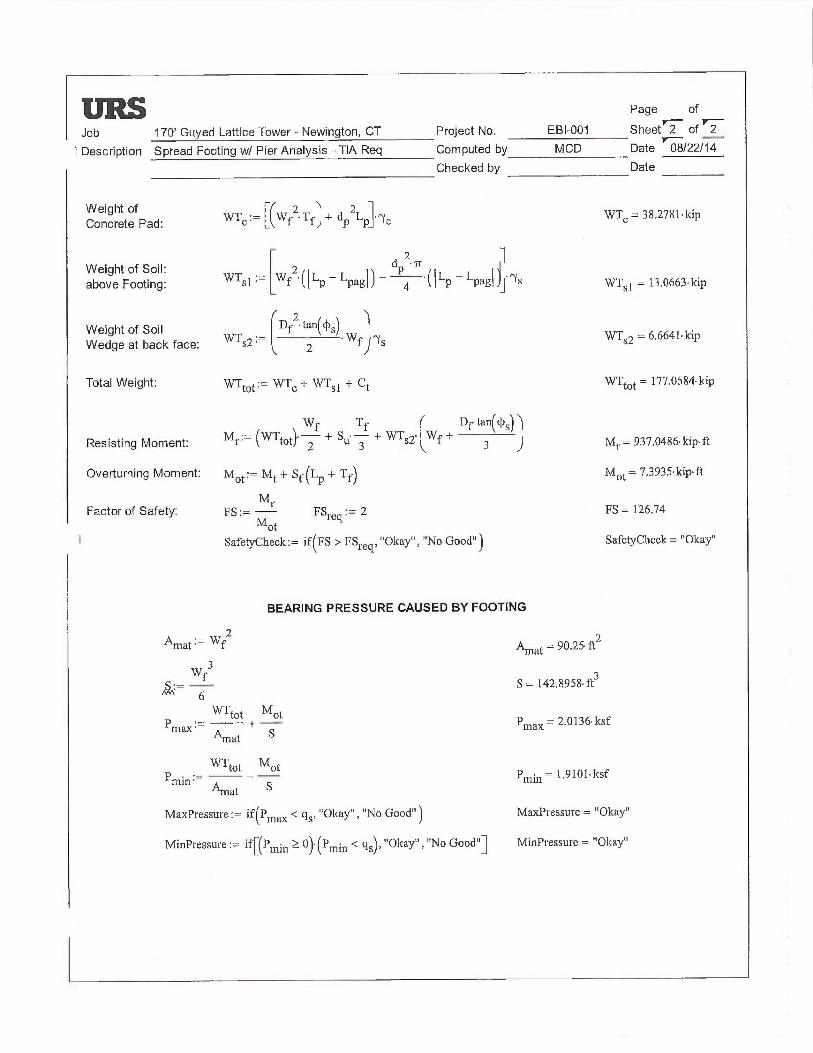
i ~ Page of
Job 170' Guyed Lattice Tower -Newington, CT Project No. EBI-001 Sheet 2 of
Description Spread Footing w/ Pier Analysis - TIA Req Computed by MCD Date 08/22/14
Checked by Date
9 ~Conlchetef Pad:
WTI:= (Wf2~Tf~+ dpZLp •rye WTI= 38.2781~kip
2 1Weight of Soil: 2 dp '~r
above Footing: WTsI ~— Wf '~ILp —Lpagl~ 4 '~ILp Lpagl~J'~s WTS1 = 13.0663•kip
Weight of Soil Df2•tan~~s~ 1
Wedge at back face: WTs2 ~- 2 ' Wf 17s WTSZ = 6,6641•lcip
Total Weight: WTtot ~- WTc + WTsI + ~t WTtot — 177.0584 kip
Wf Tf Df~tan(c~s~l
Resisting Moment: Mr~— ~WTtot}' 2 + Su 3 + WT52• Wf + 3 ) Mt = 937.0486•kip•ft
Overturning Moment: Iy1ot;— Mt + St~ ~Lp + T f) Mot = 7,3935• kip• ft
Mt.Factor of Safety: FS ;_ — FSTeq:= 2 FS = 126.74
Mot
~ SafetyCheck:= if~FS > FSleq, "Okay", "No Good") SafetyChecic= "Okay"
BEARING PRESSURE CAUSED BY FOOTING
2Amat ~- Wf
w 3f
~~ — —6WT~ot Mot
Pmax ~— + —Amat S
tot MotPmin ~ ~ S
Amat
MaxPressure:= if~Pmax ~ qs> ~~Olcay", "No Good")
MinPressure;= if~~P~in ~ ~~~'~prain ~ qs~~ ~~Okay", "No Good"]
~'tnat - 90,25 ft2
S = 142.8958• ft3
Pmax — 2•U136• ksf
Pmin - 1.9101 ~ ksf
MaacPressure = "Okay"
MinPressure = "Okay"

ANCHOR DETAILS
36931279.00000 170' Guyed Lattice Tower 8/2 212 01 4
EBI-D01 Newington, CT

~~~~
Job _.,~,..., ,_,,.„ Project Na,
-.l Description ~.~_ ~.,m_ Computed by
_ ,,...,_a ; w~._.~ Checked by ..
b~~~-
,,~,
~1
S'~,{1 =- f 3G~r,~
Page of _
Sheet of ~..
Date
Date
Reference
L, ~m ~ ~ n _ ~~,r~a pig,. ~ ~~~~ lid-~ ~ a ~6 -~~-r-- ~ ~Z
~. I 1 ~.~ ~ rr ~ ~+-
~,`t~~~~(~ic~~`~i = ~;~, f'1
i f~ o ; ~i r
c' d D i; L ~~ ~~,-- ~
c~ = ~~3 x dr = ~~~K 3~?~= ~~1~-~~ _`~
c~ = P,~ Xa~ ~ = 0,3 ~ 1~,7s~ `~~ t L~~`r~
~ (~X ~'r~~,`n~~a k~~~ ~p~~ " ~~~
~~ZC~pG~ (~r7'5,~~~— ~t 1i. (~~~1`{ ~ 3 06' h'r~~ _ 1 f, ) ~"rt~iJ
m Z ~ X~~ki,~n JC~'~~~ ~ (c~a--~ _ KG,~xGc)~g~7~,+r1—~'~~`~'~)1 ~ (7 ~ k~r~cr~ = l~(4 ~~t~-F~-~".
M ~ ~kG Z ~~ ~' --A~ L ~ ~~ e~ ~'e !;, 7t..~h - ~ ~ ~► r~/~ =- ~ga~S"~~'~ ~ Z~~ 3 > ~~~F~-3 t ~c S, ~ ~d~ /) ~ ~~ }~ ~~~s~.~ = 7`S~ ~C ~~i = 6~ ~ 7~~- ~t-F ~Mac (4~~,~n~o~rs.5 (~(~ ~ p~~) = (`i~~ ~ x~~~(i~,75 ~~~ - ~a
! ~ 7r ~' ~k ~'~---
~_ _ ~a ~

~~
Job : Calahan Tower- Newington, CT Project No.:
Description: Anchor Block Evaluation Computed by:
Anchor Block A Checked by:
Page of
E81-001 Sheet 1 of 2MCD Date 8/22/14
Date
CHECK UPLIFT RESISTANCE
RESULT5 FROM COMPUTER ANALYSIS:
Uplift = 53.255 kipsSliding = 46.561 kips
CONCRETE PARAMETERS:
~ conc - 150 pcf
w = 4 fth = 1.833333 fkd = 12 ft
Vol. = 87.999984 ft3
We = 13.20 kips
SOIL PARAMETERS:
`soil ' 130 pcf
hsof~ = 7 ft
x = 4.04 ft
Soil Weight (Wr):
(1) = 43.68 kips(2) = 44.13 kips
(3) = 14.71 kips(4) = 15.56 kips
'(5 Anchor Reinf. = 0 kipsTotal = 118.09 kips
CHECK UPLIFT (PER EIAITIA-222-F STANDARD):
Foundation Plan View
Wr/2.0 + We 11.25 > UPLIFT (Wr+ Wc) 11.5 > UPLIFT
69.60 > 53.255 OK 87.53 > 53.255 OK
CHECK UPLIFT (PER 2005 CT BLDG CODE 3108.4):
(Wr+ Wc) /2.0 > UPLIFT 65.64 > 53.255 OK
GUY ANCHORS AGAINST UPLIFT ARE ADEQUATE
~. x ~~.. _ ._ ._w ._.... - .: w X
h~a
:~}t deg
h
Foundation Section
4.04 ft
~4) ~3) 4.04
4 ft ft
(2) 12 ft FOI
F~~)

Job : Calahan Tower -Newington, CT Project No.:
Description: Anchor Block Evaluation Computed by:
Anchor Block A Checked by:
EBI-001MCD
Page of
Sheet 2 of 2
Date 8/22/14
Date
CHECK SLIDING RESISTANCE
ANCHOR PARAMETERS
Ysoll = 130 pcf
hso;i = 7 ft
h = 1.833333 ft
= 30 degrees
w = 4.0 ft
h = 1.8 ft
d = 12.0 ft
Foundation Elevation View
Ka = 0.33 Kp = 3.00
D = 2.67
HORIZONTAL FORCES
1 = 53.39 k
2 = 3.50 k
RESIST TO SLIDING = 56.88 k
SOIL &CONCRETE WEIGHT = Wr+ We = 131.29 k
UPLIFT REACTIONS = -53.255 k
5UM = 78.03 k
COEF. OF FRICTION, (0.5) = 39.02 k
RESIST TO SLIDING = 56.88 k
SUM = 95.90 k
5F AGAINST SLIDING
SF = 2.06 > 2.0 OK
GUYANCH~RSAGAINSTSLIDINGAREADEQUATE

Page of
Job : Cafahan Tower -Newington, CT Project No,: EBI-001 Sheet 1 of 2'~ Description: Anchor Block Evaluation Computed by: MCD Date 8!22/14
Anchor Block B Checked by: Date
CHECK UPLIFT RESISTANCE
RESULTS FROM COMPUTER ANALYSIS:
Uplift = 49.905 kipsSliding = 47.294 kips
CONCRETE PARAMETERS:
y conc ' 150 pcf
w = 4 fth = 1.833333333 ftd = 12 ft
Vol. = 87.99999998 ft3
We = 73.20 kips
SOIL PARAMETERS:
Ysoil - 130 pcf
hsa;i = 7 ft
x = 4.04 ft
Soil Weight (Wr):
(1) = 43.68 kips(2) = 44.13 kips
(3) = 14.71 kips(4) = 15.56 kips
k(5) Anchor Reinf. = 0 kipsTotal = 118.09 kips
x w x
hso;~
3g deg
h
(4)
~z)
Foundation Section
4.04 ft
~3~ 4.04
4 ft ft
12 ft FORCE
F(1)
Foundation Plan View
CHECK UPLIFT (PER EIAITIA-222-F STANDARD):
Wr / 2.0 + We 1 1.25 > UPLIFT (Wr+ Wc) / 1.5 > UPLIFT
69.60 > 49.905 OK 87.53 > 49.905 OK
CHECK UPLIFT (PER 2005 CT BLDG CODE 31D8.4):
(Wr + Wc) / 2.0 > UPLIFT 65.64 > 49.905 OK~ GUYANCHORS AGAINST UPLIFT ARE ADEQUATE

Job : Calahan Tower -Newington, C7 Project No.:Description: Anchor Block Evaluation Computed by:
Anchor Block B Checked by:
EBI-001MCD
Page ofSheet 2 of 2Date 8/22/14Date
CHECK SLIDING RESISTANCE
P
ysoil = 130 pcf
hsoil ~ 7 ft
h = 1.833333 ft
= 30 degrees
Ka = 0.33
ANCHOR PARAMETERS
w = 4.0 ft
h = 1.8 ft
d = 12.0 ft
hsa~i
W
a
z Fi 1
a
Foundation Elevation View
KP = 3.00
Q = 2.67
HORIZONTAL FORCES
1=
2=
RESIST TO SLIDING =
SOIL &CONCRETE WEIGHT =UPLIFT REACTIONS =
SUM =
GOEF. OF FRICTION, (0.5) _RESIST TO SLIDING =
SUM =
53.39 k
3.50 k
56.88 k
Wr+Wc= 131.29 k-49.905 k81.38 k
40.69 k56.88 k97.57 k
SF AGAINST SLIDING
SF = 2.06 > 2.0 OK
> GUYANCHORS AGAINST SLIDING ARE ADEQUATE

Job : Calahan Tower -Newington, CT Project No.:
1 Description: Anchor Block Evaluation Computed by;Anchor Block C Checked by:
x w x
hson
3g:deg'/
';'
hi
CHECK UPLIFT RESISTANCE
RESULTS FROM COMPUTER ANALYSIS:
Uplift = 47.401 kipsSliding = 47.717 kips
CONCRETE PARAMETERS:
Y conc ~ 150 pcf
w = 4 fth = 1.833333333 ftd = 12 ft
Vol. = 88 ft3
We = 73,20 kips
SOIL PARAMETERS:
soil - 130 pcf
hso;i = 7 ft
x = 4.04 ft
Soil Weight (Wr):
(1) = 43.68 kips(2) = 44.13 kips
(~) = 14.71 kips(4) = 15.56 kips
"(5) Anchor Reinf. = 0 kipsTotal = 118,09 kips
Foundation Plan View
CHECK UPLIFT (PER EIA/TIA-222-F STANDARD):
Wr / 2,0 + We / 1.25 > UPLIFT (Wr + Wc) / 1.5 > UPLIFT
69.60 > 47.407 OK 87.53 > 47.401 OK
CHECK UPLIFT (PER 2005 CT BLDG CODE 3108.4):
(Wr + Wc) / 2.0 > UPLIFT 65.64 > 47.401 OKGLIYANCHORS AGAINST UPLIFT ARE ADEQUATE
FORCEI
F
Page of
EBI-001 Sheet 1 of 2MCD Date 8/22/14
Date
Foundation Section
4.04 ft(4) ~3) 4.04
4 ft fl
(2) 12 ft
(1)

Job : Calahan Tower -Newington, CT Project No.:Description: Anchor Block Evaluation Computed by:
Anchor Block C Checked by:
w
a
2 ~ i ~'
a
Foundation Elevation View
(CHECK SLIDING RESISTANCE
ANCHOR PARAMETERS
h~o~i
Ysoif = 130 pcf
hsoil — 7 ft
h = 1.833333 ft
~= 30 degrees
1~a = 0.33
w = 4.0 ft
h = 1.8 ft
d = 12.0 ft
KP = 3.00
Page of
EBI-001 Sheet 2 of 2MCD Date 8/22/14
Date
D = 2.67
HORIZONTAL FORCES
1=
2=
RESIST TO SLIDING =
SOIL &CONCRETE WEIGHT =UPLIFT REACTIONS =
SUM =
53.39 k
3.50 k
56.88 k
Wr+Wc= 131.29 k-47.401 k
83.89 k
COEF. OF FRICTION, (0.5) _RESIST TO SLIDING =
SUM =
41.94 k56.88 k
98.83 k
SF AGAINST SLIDING
SF = 2.07 > 2.0 OK
—► GUYANCHORS AGAINST SLIDING ARE ADEQUATE


EBI Consulting~, environmental ~ engineering ~ due diligence
RADIO FREQUENCY EMISSIONS ANALYSIS REPORTEVALUATION OF HUMAN EXPOSURE POTENTIAL
TO NON-IONIZING EMISSIONS
T-Mobile Existing Facility
Site ID: CT11174A
Callahan Tower99 Cedar Wood LaneNewington, CT 06111
August 28, 2014
Site Compliance Summary
Compliance Status: COMPLIANT
Site total MPE% of
FCC general public 88,39allowable limit:
21 B Street Burlington, MA 01803 Tel: (781) 273.250 Fax: (781) 273.3311

E61 Cons~~~~~,, environmental ~ engineering ~ due diligence
August 28, 2014
T-Mobile USAAttn: Jason Overbey, RF Manager35 Griffin Road SouthBloomfield, CT 06002
Emissions Analysis for Site: CT11174A —Callahan Tower
EBI Consulting was directed to analyze the proposed T-Mobile facility located at 99 Cedar Wood Lane,
Newington, CT, for the purpose of deternuning whether the emissions from the Proposed T-Mobile
Antenna Installation located on this property are within specified federal limits.
All information used in this report was analyzed as a percentage of current Maximum Permissible
Exposure (% MPE) as listed in the FCC OET Bulletin 65 Edition 97-Oland ANSI/IEEE Std C45.1. The
FCC regulates Maximum Permissible Exposure in units of microwatts per square centimeter (µW/cm2).
The number of µW/cm2 calculated at each sample point is called the power density. The exposure lunit
for power density varies depending upon the frequencies being utilized. Wireless Carriers and Paging
Services use different frequency bands each with different exposure lunits, therefore it is necessary to
report results and limits in terms of percent MPE rather than power density.
.All results were compared to the FCC (Federal Communications Commission) radio frequency exposure
rules, 47 CFR 11307(b)(1) — (b)(3), to determine compliance with the Ma7cimum Permissible Exposure
(MPE) limits for General Population/i.Tncontrolled environments as defined below..
General population/uncontrolled exposure limits apply to situations in which the general public may be
exposed or in which persons who are exposed as a consequence of their employment may not be made
fully aware of the potential for exposure or cannot exercise control over their exposure. Therefore,
members of the general public would always be considered under this category when exposure is not
employment related, for example, in the case of a telecommunications tower that exposes persons in a
nearby residential area.
Public exposure to radio frequencies is regulated and enforced in units of microwatts per square
centimeter (µW/cm2). The general population exposure limit far the 700 MHz Band is 467 µW/cm2, and
the general populafion exposure limit for the PCS and AWS bands is 1000 µW/cm2. Because each carrier
will be using different frequency bands, and each frequency band has different exposure limits, it is
necessary to report percent of MPE rather than power density.
21 B Street Burlington, MA 01803 Tel: (781) 273.2500 Fax: (781j 273.3311

EBI Consultingw environmental ~ engineering ~ due diligence
OccupationaUcontrolled exposure limits apply to situations in which persons are exposed as a
consequence of their employment and in which those persons who are exposed have been made fully
aware of the potential for exposure and can exercise control over their exposure. OccupationaUcontrolled
exposure limits also apply where exposure is of a transient nature as a result of incidental passage through
a location where exposure levels may be above general populatian/uncontrolled limits (see below), as
long as the exposed person has been made fully aware of the potential for exposure and can exercise
control over his or her exposure by leaving the area or by some other appropriate means.
Additional details can be found in FCC OET 65.
CALCULATIONS
Calculations were done for the proposed T-Mobile Wireless antenna facility located at 99 Cedar Wood
Lane, Newington, CT, using the equipment information listed below. All calculations were performed
per the specifications under FCC OET 65. Since T-Mobile is proposing highly focused directional panel
antennas, which project most of the emitted energy out toward the horizon, all calculations were
performed assuming a lobe representing the maximum gain of the antenna per the antenna manufactures
supplied specifications, minus 10 dB, was focused at the base of the tower. For this report the sample
point is the top of a 6 foot person standing at the base of the tower.
For all calcularions, all equipment was calculated using the following assumptions:
1) 2 GSM channels (PCS Band -.1900 MHz) were considered for each sector of the proposed
installation. These Channels have a transmit power of 30 Watts per Channel
2) 2 UMTS channels (AWS Band — 2100 MHz) were considered for each sector of the proposed
installation. These Channels have a transmit power of 30 Watts per Channel.
3) 2 LTE channels (AWS Band — 2100 MHz) were considered for each sector of the proposed
installation. These Channels have a transmit power of 60 Watts per Channel.
4) 1 LTE channel (700 MHz Band) was considered for each sector of the proposed installation.
This channel has a transmit power of 30 Watts.
5) All radios at the proposed installation were considered to be running at full power and were
uncombined in their RF transmissions paths per carrier prescribed configuration. Per FCC
OET Bulletin No. 65 - Edirion 97-01 recommendations to achieve the ma~cimum anticipated
value at each sample point, all power levels emitting from the proposed antenna installation
are increased by a factor of 2.56 to account for possible in-phase reflections from the
surrounding environment. This is rarely the case, and if so, is never continuous.
21 B Street 'Burlington, MA 01803 Tel: (781) 273.2500 Fax: (781) 273.3311

EBI Consulting~„ environmental ~ engineering ~ due diligence
6) For the following calculations the sample point was the top of a s~ foot person standing at
the base of the tower. The m~imum gain of the antenna per the antenna manufactures
supplied specifications minus 10 dB was used in this direction. This value is a very
conservative estimate as gain reductions for these particular antennas are typically much
higher in this direction.
7) The antennas used in this modeling are the RFS APXI6DWV-16DWVS-E-A20 for 1900
MHz (PCS) and 2100 MHz (AWS) channels and the Commscope LNX-6515DS-VTM for
700 MHz channels. This is based on feedback from the carrier with regards to anticipated
antenna selection. The RFS APXI6DWV-16DWVS-E-A20 has a maxirrium gain of 16.3
dBd at its main lobe. The Commscope LNX-6515DS-VTM has a ma~mum gain of 14.6
dSd at its main lobe. The ma~mum gain of the antenna per the antenna manufactures
supplied specifications, minus 10 dB, was used for all calculations. This value is a very
conservative estimate as gain reductions for these particular antennas are typically much
higher in this direction.
8) The antenna mounting height centerline of the proposed antennas is 163 feet above ground
level (AGL).
9) Emissions values for additional carriers were taken from the Connecticut Siting Council
active database. Values in this database are provided by the individual carriers themselves.
All calculations were done with respect to uncontrolled /general public threshold limits.
21 8 Street 'Burlington, MA 01803 Tel: (781) 273.2500 Fax: (781) 273.3311

EBI nsultinr., environmental ~ engineering ~ due diligence
T-Mobile Site Inventory and Power Data
Sector: A Sector: B Sector: CAntenna #: 1 Antenna #: 1 Antenna #: 1
RFS APXI6DWV- RFS APXI6DWV- RFS APXI6DVJV-Make/Model 16DWVS-E-A20
Make/Model: 16DWVS-E-A20
MakelModel: 16DWVS-E-A20
Gain: 163 dBd Crain: 163 dBd Gain:. 16.3 dBdHei ht (AGL): 163 Hei ht (AGL): 163 Hei ht (AGL): 163
Fz~equency Bands 1900 MHz(PCS) /
Frequency Bands 1900 MHz(PCS) /
FrequencyBands 1900 MHz(PCS) /
2100 MHz (AWS) 2100 MHz (AWS) 2100 MHz (AWS)Channel Count 6 Channel Count 6 # PCS Channels: 6
Total TX Power: 240 Total TX Power: 240 # AWS Channels: 240ERP (~: 3,833.82 ERP (P~: 3,833.82 ERP (V~: 3,833.82
Antenna Al MPE% 1.49 Antenna B I MPE°lo 1.49 Antenna Cl MPE% 1.49
Antenna #: 2 Antenna #: 2 Antenna #: 2Commscope LNX- Commscope LNX- Couunscope LNX-
Make /Mode]: 6515DS-V'I'M
Make /Model: 6515DS-VTM
Make /Model: 6515DS-VTM
Gain: 14.6 dBd Gain: 14.6 dBd Crain: 14.6 dBdHeight (AGI,): 163 Height (AGL): 163 Height (AGL): 163
Fr uenc Bands 700 Mhz Fre enc Bands 700 Mhz Fr uenc Bands 700 MhzChaone] Count 1 Channel Count 1 Channel Count 1
Total TX Power: 30 Total TX Power: 30 Total TX Power: 30ERP (~: 445.37 ERP (VV): 44537 ERP (V~: 445.37
Antenna A2 MPE% 0.27 Antenna B2 MPE% 0.27 Antenna C2 MPE%n 0.27
Site Com osite MPE%Carrier MPE%
T-Mobile 5.29
AT&T 22.33 %
Clearwue 0.91 %
Nextel 3.88 %
Carbone's Auto Body 55.20 %
Town of Weathersfield 0.78 %
Site Tota1114PE %: 88.39 %
T-Mobile Sector 1 Total: 1.76 %T-Mobile Sector 2 Total: 1.76 %T-Mobile Sector 3 Total: 1.76
Site Total: 8839 %
21 B Street ~ Burlington, MA 01803 Tel; (781) 273.2500 Fax: (781) 2733311

E61 Consulting~, environmental ~ engineering ~ due diligence
Summary
All calculations performed for this analysis yielded results that were within the allowable limits for
general public exposure to RF Emissions.
The anticipated maximum composite contributions from the T-Mobile facility as well as the site
composite emissions value with regards to compliance with FCC's allowable limits for general public
exposure to RF Emissions are shown here:
T-Mobile Sector Power Density Value (%)Sector 1: 1.76 %Sector 2: 1.76 °IoSector 3 : 1.76 %
T-Mobile Total: 5.29 %
Site Total: 88.39 %
Site Compliance Status: COMPLIANT
The anticipated composite MPE value for this site assuming all carriers present is 88.39% of the
allowable FCC established general public limit sampled at the ground level. This is based upon values
listed in the Connecticut Siring Council database for e~sting carrier emissions.
FCC guidelines state that if a site is found to be out of compliance (over allowable thresholds), that
carriers over a 5% contribution to the composite value will require measures to bring the site into
compliance. For this facility, the composite values calculated were well within the allowable 100%
threshold standard per the federal government.
i%_ ~ ~ ---~~ / % —~'_/j~:
Scott Heffernan
RF Engineering Director
EBI Consulting
21 B Street
Burlington, MA 01&03~
21 B Street ~ Burlington, MA 01503 Tel: (781) 273.2500 Fax: (781) 273.3311