Embed Size (px)
Citation preview

GMR 404/406marine radar
installation instructions

© 2006–2010 Garmin Ltd. or its subsidiaries
Garmin International, Inc. 1200 East 151st Street, Olathe, Kansas 66062, USA Tel. (913) 397.8200 or (800) 800.1020 Fax (913) 397.8282
Garmin (Europe) Ltd. Unit 5, The Quadrangle, Abbey Park Industrial Estate, Romsey, SO51 9LR, UK Tel. +44 (0) 870.8501241 (outside the UK) 0808 2380000 (within the UK) Fax +44 (0) 870.8501251
Garmin Corporation No. 68, Jangshu 2nd Road, Sijhih, Taipei County, Taiwan Tel. 886/2.2642.9199 Fax 886/2.2642.9099
All rights reserved. Except as expressly provided herein, no part of this manual may be reproduced, copied, transmitted, disseminated, downloaded or stored in any storage medium, for any purpose without the express prior written consent of Garmin. Garmin hereby grants permission to download a single copy of this manual onto a hard drive or other electronic storage medium to be viewed and to print one copy of this manual or of any revision hereto, provided that such electronic or printed copy of this manual must contain the complete text of this copyright notice and provided further that any unauthorized commercial distribution of this manual or any revision hereto is strictly prohibited.Information in this document is subject to change without notice. Garmin reserves the right to change or improve its products and to make changes in the content without obligation to notify any person or organization of such changes or improvements. Visit the Garmin Web site (www.garmin.com) for current updates and supplemental information concerning the use and operation of this and other Garmin products.Garmin® is a trademark of Garmin Ltd. or its subsidiaries, registered in the USA and other countries, and may not be used without the express permission of Garmin.
March 2010 Part Number 190-00669-02 Rev. C Printed in Taiwan

GMR 404/406 Marine Radar Installation Instructions �
WelcomeThank you for choosing the Garmin GMR 404/406. These instructions help you assemble and install the GMR 404/406 radar. To install your Garmin chartplotter, consult the installation instructions packaged with the chartplotter.
Product RegistrationHelp us better support you by completing our online registration today! Connect to our Web site at www.garmin.com/registration/.
Use this area to record the serial number (8-digit number located on the back of the GMR 404/406 pedestal door, or on the product packaging) in case your GMR 404/406 needs service. Keep the original sales receipt, or a photocopy, in a safe place.
Serial Number: ___ ___ ___ ___ ___ ___ ___ __
Contact GarminContact Garmin if you have any questions while using your GMR 404/406. In the USA contact Garmin Product Support by phone: (913) 397-8200 or (800) 800-1020, Monday–Friday, 8 AM–5 PM Central Time; or go to www.garmin.com/support/, and click Product Support.
In Europe, contact Garmin (Europe) Ltd. at +44 (0) 870.8501241 (outside the UK) or 0808 2380000 (within the UK).
Note: The Garmin GMR 404/406 has no user-serviceable parts. If you encounter a problem with your unit, please take it to an authorized Garmin NMEA dealer or contact Garmin Product Support for repairs.
Packing ListBefore installing and getting started with your unit, please check to see that your package includes the following items. If any parts are missing, please contact your Garmin dealer immediately.Standard Package:
• GMR 404 or 406 radar pedestal and antenna• Power/marine network cable• Voltage Converter• Hardware kit• Installation manual
�
InstallatIon
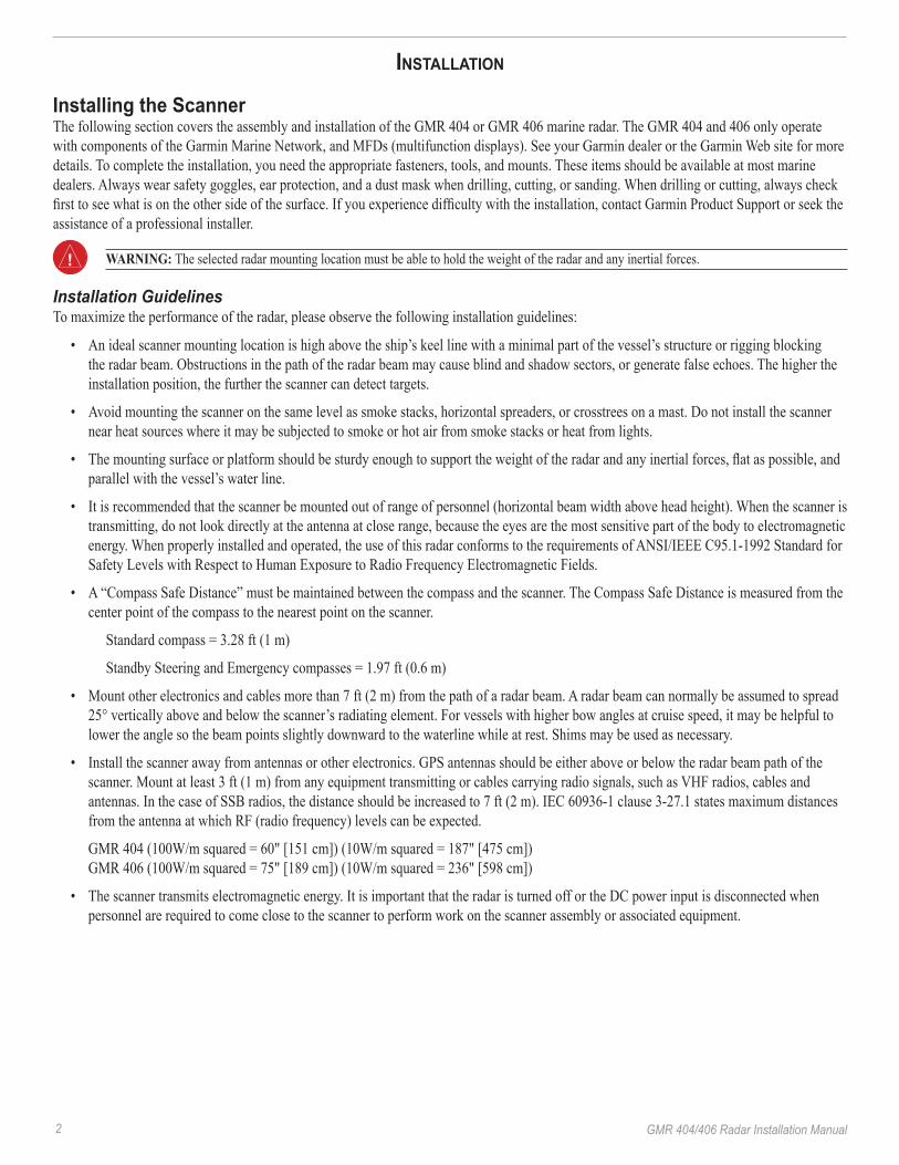
Installing the ScannerThe following section covers the assembly and installation of the GMR 404 or GMR 406 marine radar. The GMR 404 and 406 only operate with components of the Garmin Marine Network, and MFDs (multifunction displays). See your Garmin dealer or the Garmin Web site for more details. To complete the installation, you need the appropriate fasteners, tools, and mounts. These items should be available at most marine dealers. Always wear safety goggles, ear protection, and a dust mask when drilling, cutting, or sanding. When drilling or cutting, always check first to see what is on the other side of the surface. If you experience difficulty with the installation, contact Garmin Product Support or seek the assistance of a professional installer.
WarNING: The selected radar mounting location must be able to hold the weight of the radar and any inertial forces.
Installation GuidelinesTo maximize the performance of the radar, please observe the following installation guidelines:
• An ideal scanner mounting location is high above the ship’s keel line with a minimal part of the vessel’s structure or rigging blocking the radar beam. Obstructions in the path of the radar beam may cause blind and shadow sectors, or generate false echoes. The higher the installation position, the further the scanner can detect targets.
• Avoid mounting the scanner on the same level as smoke stacks, horizontal spreaders, or crosstrees on a mast. Do not install the scanner near heat sources where it may be subjected to smoke or hot air from smoke stacks or heat from lights.
• The mounting surface or platform should be sturdy enough to support the weight of the radar and any inertial forces, flat as possible, and parallel with the vessel’s water line.
• It is recommended that the scanner be mounted out of range of personnel (horizontal beam width above head height). When the scanner is transmitting, do not look directly at the antenna at close range, because the eyes are the most sensitive part of the body to electromagnetic energy. When properly installed and operated, the use of this radar conforms to the requirements of ANSI/IEEE C95.1-1992 Standard for Safety Levels with Respect to Human Exposure to Radio Frequency Electromagnetic Fields.
• A “Compass Safe Distance” must be maintained between the compass and the scanner. The Compass Safe Distance is measured from the center point of the compass to the nearest point on the scanner.
Standard compass = 3.28 ft (1 m)
Standby Steering and Emergency compasses = 1.97 ft (0.6 m)
• Mount other electronics and cables more than 7 ft (2 m) from the path of a radar beam. A radar beam can normally be assumed to spread 25° vertically above and below the scanner’s radiating element. For vessels with higher bow angles at cruise speed, it may be helpful to lower the angle so the beam points slightly downward to the waterline while at rest. Shims may be used as necessary.
• Install the scanner away from antennas or other electronics. GPS antennas should be either above or below the radar beam path of the scanner. Mount at least 3 ft (1 m) from any equipment transmitting or cables carrying radio signals, such as VHF radios, cables and antennas. In the case of SSB radios, the distance should be increased to 7 ft (2 m). IEC 60936-1 clause 3-27.1 states maximum distances from the antenna at which RF (radio frequency) levels can be expected.
GMR 404 (100W/m squared = 60" [151 cm]) (10W/m squared = 187" [475 cm]) GMR 406 (100W/m squared = 75" [189 cm]) (10W/m squared = 236" [598 cm])
• The scanner transmits electromagnetic energy. It is important that the radar is turned off or the DC power input is disconnected when personnel are required to come close to the scanner to perform work on the scanner assembly or associated equipment.
GMR 404/406 Radar Installation Manual

GMR 404/406 Marine Radar Installation Instructions �
Step Install the Mounting Studs and Seals:1. RemovethehatchonthefrontofpedestalbylooseningthescrewandliftingthehatchoffofthehingesasshowninFigure1.2. Usinga5mmAllenwrench,installtheM10x71mountingstuds(Figure2)inthepedestalmatchingtheholepatternthatwasselected.
Tightenthemountingstudsuntiltheybottomoutinthepedestal.DONOTovertightenthestudsbecausethismaycausedamagetothepedestal.Themountingstudshaveathreadlockingpatchappliedatthefactory.
OPTIONAL—Applymoistureinhibitivegreaseorpastetothefourstudspriortoinstallation.3. InstalltheSealsontothepedestal(Figure3).
Figure 1 Figure 2
Figure 5
Step Mount the ScannerThe scanner can be mounted with either end pointed toward the bow as long as it is mounted along the Bow-Stern Axis line indicated on the Mounting Template. If the end with the hatch is pointed toward the bow, the Bearing Offset in the chartplotter must be set to 180° (Figure 4).
To mount the scanner:1. DetermineasuitablemountinglocationandtapetheMountingTemplateinplace.TheMountingTemplatehastwoholepatternsOption
A and Option B. Determine which pattern fits your mount or better suits your mounting location. Using a Center Punch, indent the center ofeachmountinghole.Usinga13mm(1/2")bit,drillthefourmountingholes.(Thisstepisnotnecessaryifyouareusingapre-drilledGarmincompatibleFuruno®orRaymarine®mount).
2. Hoistthescannerintopositionusingthesuppliedstrap.PositionthestrapovertheendsoftheantennamountasshowninFigure5.Makesurethatthestrapispositionedasclosetothescanneraspossible.
3. Fasten the scanner to the mounting surface using the M10 hex nuts, spring washers, and flat washers in the order shown in Figure 6. The M10 nuts should be torqued to 130 in.lbs (11 ft.lbs) (1.5 kgf.m).
Figure 6
flat washer
spring washer
M10 hex nut
Figure 3
bow
stern
Bearing Offset = 0°
Bearing Offset = �80°
Figure 4

4 GMR 404/406 Marine Radar Installation Instructions
Step Mount the Antenna:1. Removetheprotectivecoverfromthepedestalwaveguide.2. Verifythattheantennawaveguideisalignedwiththepedestalwaveguideandslidetheantennaontothepedestal.3. Securetheantennatothepedestalusingthe8mmhexboltsandspringwashers.The 8 mm bolts should be torqued to 70 in.lbs
(6 ft.lbs) (.81 kgf.m).
align waveguide faces
15 Amp Slow Blow Fuse
To scanner power cable
Figure 7Wire Gauge Table
Distance Gauge3 meters (9.8 ft) 12 AWG5 meters (16.4 ft) 10 AWG6.5 meters (21.3 ft) 9 AWG8 meters (26.2 ft) 8 AWG
To RF ground
To s
hip’
s po
wer
Step Install the Voltage Converter UnitThe voltage converter requires an input voltage of 10-40VDC and provides an output of 36 VDC. The converter must be fused using a 15 Amp slow-blow fuse. It is recommended that voltage converter be installed as close as possible to the selected power source. If the input wires need to be extended, follow the recommendations in Figure 7. If the wires are extended, use the supplied heat shrink butt connectors. After the connector is crimped, heat the connector to shrink it for a water resistant fit. For optimal performance, the voltage converter housing should be connected to the vessel’s RF ground.

GMR 404/406 Marine Radar Installation Instructions �
Figure 9 Figure 10
Figure 8
Step Install the Cable Assembly Route the cable as needed, depending on the type of mount you are using. DO NOT cut the cable! It may be necessary to drill a 31.7 mm (1.25") hole for routing the power/network cable. Garmin provides a rubber cable grommet that can be used to cover the cable installation hole. The grommet does NOT provide a waterproof seal. To waterproof the grommet, apply a marine sealant. You can purchase additional cable grommets through Garmin or a Garmin dealer.
When installing the power/network cable, observe the following:
• To ensure safety, use the appropriate tie-wraps, fasteners, and sealant to secure the cable along a route and through any bulkhead or deck. Avoid running the cable near moving objects, high-heat sources, or through doorways and bilges.
• Avoid installing the cable next to or parallel to other cables, such as radio antenna lines, or power cables. This is essential to avoid interference to or from other equipment. If this is not possible, shield the cable with metal conduit or a form of EMI shielding.
To install the cable assembly:1. Alignthenotchandlockingringonthepowercabletothepowerconnector.Pressthe2-pinpowercabletothepowerconnectorandthe
RJ-45marinenetworkcabletotheRJ-45socket.Turnthepowercablelockingringclockwiseuntilitstops.TightentheRJ-45lockingring clockwise until it is firmly sealed. (Figure 8)
2. Thepower/networkcablecanberoutedthroughthefrontofthescanner(Figure9),orthroughaholedrilledthroughthemountingsurface(Figure10).Avoidexcessivebendingortwistingofthecable.
3. Re-installthehatchonthefrontofthescanner.

6 GMR 404/406 Marine Radar Installation Instructions
Step Connecting the scannerConnect the scanner power cable (Red and Black) to Voltage Converter output cable (Red and Black) using the supplied heat-shrink crimp connectors. DO NOT cut the scanner cable and DO NOT remove the in-line fuse located on the scanner power cable. After crimping the connections, heat the connectors to shrink the housing for a water resistant fit.
Connect the scanner to the vessel’s water ground using an 8 gauge copper cable. The scanner connection should be made on one of the four mounting studs using a M10 nut and flat washer to secure the cable.
Wiring Diagram

GMR 404/406 Marine Radar Installation Instructions �
Step Connection the network: Forastand-alonenetwork(chartplotterandradaronly),attachtheRJ-45marinenetworkcabletotheRJ-45socketonthebackofthe
chartplotter.Foranexpandednetwork(chartplotter,radar,GMS10),attachtheRJ-45marinenetworkcabletoanopenRJ-45socketonthe GMS 10 network power expander. Tighten the RJ-45 locking ring clockwise until it is firmly sealed.
Note: Each component of the expanded network must be installed according to its installation instructions. These diagrams only show how a GMR 404/406 radar interacts with a network and do not show proper wiring for other network components.
Stand Alone Network
Expanded Network
Serial cableEthernet cableTransducer cablexxxxxxxxx

8 GMR 404/406 Marine Radar Installation Instructions
Radar SetupTo take advantage of the GMR 404/406 features, the Garmin Marine Network may require a software update. A software update card is provided in the Marine Data Management Kit.
The newly installed GMR 404 or 406 will not transmit until the radar is properly configured. Follow the instructions below to properly configure the radar.
Turn on the Garmin Marine Network:1. PressthePowerkeyonthechartplotter.Thescannerturnsonwiththenetwork.TheWelcomePageappearsshowingthataGMR
404/406 is detected as a network connection.2. WhentheI Agreebuttonturnsyellow,presstheENTERkey.
Configure the Radar:1. FromtheMapPage,pressQUIT to clear the message “Radar Needs Configured” and show the Radar Setup Page.2. UsingtheROCKER,highlighttheAdvancedtab,thentheAntenna Size field, and press ENTER.3. Selectthecorrectantennasize,4 footor6 foot,andpressENTER.4. Whenprompted,pressandholdFCTNtobeginradartransmission.Beforebeginningradartransmission,verifythattheareaaroundthe
scannerisclear.Microwaveenergycanbeharmfultohumansandanimals.Whiletheradaristransmitting,avoidlookingdirectlyatthescanner.Theeyesarethemostsensitivepartofthebodytomicrowaveradiation.
Select Antenna Size
Front of Boat OffsetDepending on the scanner installation, it may be necessary to adjust the Front of Boat Offset. If the scanner installation requires a 180° offset, change the Front of Boat Offset to 180° and test the radar. If the Front of Boat Offset needs further adjustment, continue with the procedure below.
Using a magnetic compass, take an optical bearing of a stationary target located within viewable range. Measure the target bearing on the radar. If the bearing deviation is more than +/- 1°, then do the following to correct the Front of Boat Offset.
To change the Front of Boat Offset:1. FromtheRadarPage,presstheADJkeytodisplaytheAdjustmentMenu.2. FromtheAdjustmentMenu,selectSetup,andpressENTER.UsingtheRocker,selecttheAdvancedtab.3. UsingtheROCKER,highlighttheFront of Boat Offsetslider,andpressENTER.4. PressleftontheRocker toadjusttoanegativevalue,orpressrighttoadjusttoapositivevalue.Thepreviewwindowchangesasyou
adjusttheslider.5. Afteranoffsetisdetermined,pressENTERtosave,andpressQUITtoreturntotheRadarPage.YournewGarminMarineRadarisnow
readytouse!Refertoyourchartplotter'sOwner’s Manualfordetailsaboutoperatingtheradar.
Stopping the RadarWhen you enter standby mode, the antenna will stop spinning, but the magnetron will remain charged. This means that the Radar can be quickly turned on again without having to warm up.
To place the GMR 404/406 in Standby mode:1. Fromanypage,pressandholdtheFCTNkey.2. UsingtheROCKER,highlightYes andpressENTER.
Note: When the radar is placed into standby mode, the GMR 404/406 antenna will reduce its spinning speed for approximately 15 seconds, then stop perpendicular to the length of the boat, or as defined by the Front of Boat Offset.

GMR 404/406 Marine Radar Installation Instructions �
Specifications4 ft Open-Array Antenna:Type: End fed slotted waveguide
Horizontal Beamwidth: 1.8 degrees
Horizontal Sidelobes: -23 dB within ±10 deg of main
-30 dB outside ±10 deg of main
Vertical Beamwidth: 24 degrees
Antenna Gain: 29 dBi
Polarization: Horizontal
Input Return Loss Better than -20 dB
Weight 12 lbs (5.4 kg)
6 ft Open-Array Antenna:Type: End fed slotted waveguide
Horizontal Beamwidth: 1.1 degrees
Horizontal Sidelobes: -25 dB within ±10 deg of main
-30 dB outside ±10 deg of main
Vertical Beamwidth: 24 degrees
Antenna Gain: 30 dBi
Polarization: Horizontal
Input Return Loss: Better than -20 dB
Weight: 16 lbs (7.3 kg)
Open-Array ScannerTransmit Power: 4 kW
Transmitter Frequency: 9410 ±30 MHz
Input Voltage: 10.5 – 38 VDC
Typical Input Power: 45 W
Input Power (100 kts wind): 130 W maximum
Range/Pulse Width/PRF (nm/nsec/Hz): 0.125/65/2304
0.250/65/2304
0.500/80/2304
0.750/200/1152
1.0/250/1152
1.5/500/576
2.0/500/576
3.0/800/576
4.0/800/576
6.0 – 24/1000/576
36 – 72/1000/288

�0 GMR 404/406 Marine Radar Installation Instructions
Antenna Rotation: 24 rpm and 48 rpm
Maximum wind load: 100 kts
Receiver Noise Figure: Less than 4 dB
Environmental: Temp: 14 to 140º F (-10 to +60º C)
Humidity: 95% @ 95 ºF (35 ºC)
Rel Wind: 100 kts
Waterproof to IEC 60529 IPX6
Range: 65.5 ft (20 m) minimum, 72 nm max
Range discrimination: 65.5 ft (20 m)
Radar interference: Anti-jamming algorithm
Clutter suppression: Sea Clutter
Rain Clutter
FTC
Weight: 42 lbs (19 kg)
Dimensions: 17" x 11" x 16" (43.2 x 28 x 40.6 cm)
Cable: 49.21' (15 m) long
8.4 lbs (3.8 kg)
Radar Display FeaturesPresentation Modes: North up, Course up, Heading up
VRM/EBL: 2 user adjustable, capable of floating
Bearing Accuracy: 1 degree
Controls: Auto & Manual Gain Adjust; Manual or Auto (AFC) receiver tuning; Manual adjust for Rain Clutter and 3 presets for Sea Clutter; FTC presets
Radar/Chart Overlay: Overlay mode is supported. Also has split overlay with standard radar presentation
Zoom Mode: 2x, 4x
Trails (Wakes): Short, Medium, Long
Guard Zone Alarm: 2 guard zones – user adjustable
Off center Function: Look ahead, Auto Shift and Manual
Antenna RPM Selectable to 24 or 48 rpm
MARPA: Tracks up to 10 MARPA targets for radar plotting and collision avoidance (Heading sensor is required)

GMR 404/406 Marine Radar Installation Instructions ��
5.91″
5.51″
7.87″
7.87″
L 12.87″ 326.8 mm
12.34″
17.35″
Model L GMR 404 51.6" [1310 mm]GMR 406 75.7" [1923 mm]
313.5 mm
440.8 mm
200.0 mm
200.0 mm
140.0 mm
150.0 mm

�� GMR 404/406 Marine Radar Installation Instructions
Failure to avoid the following potentially hazardous situations could result in an accident or collision resulting in death or serious injury.• Use this unit only as a navigational aid. Do not attempt to use the unit for any purpose requiring precise measurement of direction, distance, location, or
topography. • The radar scanner transmits electromagnetic energy. Ensure that the scanner has been installed according to the recommendations given in this guide,
and that all personnel are clear of the scanner before switching to transmit mode.• For protection from lightning, this installation must conform to NFPA code, section 302. The installation of a lightning protective mast is recommended,
and the scanner must be connected to water ground using an 8 gauge copper cable.
WarNING: This product, its packaging, and its components contain chemicals known to the State of California to cause cancer, birth defects, or reproductive harm. This Notice is provided in accordance with California’s Proposition 65. See www.garmin.com/prop65 for more information.
Warnings and Important Information
CaUtIoN: Use the GMR 404/406 at your own risk. To reduce the risk of unsafe operation, carefully review and understand all aspects of this Installation Manual, and thoroughly practice operation using the simulator mode prior to actual use. When in actual use, carefully compare indications from the GMR 404/406 to all available navigation sources, including the information from other NAVAIDs, visual sightings, charts, etc. For safety, always resolve any discrepancies before continuing navigation.
FCC ComplianceThe GMR 404/406 complies with Part 80 of the FCC rules. It has received a grant of equipment authorization, issued under the authority of the FCC.
This equipment generates, uses, and can radiate radio frequency energy and, if not installed and used in accordance with the instructions, may cause harmful interference to radio communications. However, there is no guarantee that interference will not occur in a particular installation. If this equipment does cause harmful interference to radio or television reception, which can be determined by turning the equipment off and on, the user is encouraged to try to correct the interference by one of the following measures:
• Reorient or relocate the receiving antenna.• Increase the separation between the equipment and the receiver.• Connect the equipment into an outlet on a circuit different from that to which the receiver is connected.• Consult the dealer or an experienced radio/TV technician for help..
This product does not contain any user-serviceable parts. Repairs should only be made by an authorized Garmin service center. Unauthorized repairs or modifications could result in permanent damage to the equipment, and void your warranty and your authority to operate this device under Part 15 regulations.
GMR 404/406 Marine Radar Installation Instructions ��
Software License AgreementBY USING THE GMR 404/406, YOU AGREE TO BE BOUND BY THE TERMS AND CONDITIONS OF THE FOLLOWING SOFTWARE LICENSE AGREEMENT. PLEASE READ THIS AGREEMENT CAREFULLY.Garmin grants you a limited license to use the software embedded in this device (the “Software”) in binary executable form in the normal operation of the product. Title, ownership rights, and intellectual property rights in and to the Software remain in Garmin.You acknowledge that the Software is the property of Garmin and is protected under the United States of America copyright laws and international copyright treaties. You further acknowledge that the structure, organization, and code of the Software are valuable trade secrets of Garmin and that the Software in source code form remains a valuable trade secret of Garmin. You agree not to decompile, disassemble, modify, reverse assemble, reverse engineer, or reduce to human readable form the Software or any part thereof or create any derivative works based on the Software. You agree not to export or re-export the Software to any country in violation of the export control laws of the United States of America.
Limited WarrantyAll Garmin marine radomes and open array scanners are warranted to be free from defects in materials or workmanship for two years from the date of purchase. Within this period, Garmin will, at its sole option, repair or replace any components that fail in normal use. Such repairs or replacement will be made at no charge to the customer for parts or labor, provided that the customer shall be responsible for any transportation cost. This warranty does not cover failures due to abuse, misuse, accident, or unauthorized alteration or repairs.THE WARRANTIES AND REMEDIES CONTAINED HEREIN ARE EXCLUSIVE AND IN LIEU OF ALL OTHER WARRANTIES EXPRESS, IMPLIED, OR STATUTORY, INCLUDING ANY LIABILITY ARISING UNDER ANY WARRANTY OF MERCHANTABILITY OR FITNESS FOR A PARTICULAR PURPOSE, STATUTORY OR OTHERWISE. THIS WARRANTY GIVES YOU SPECIFIC LEGAL RIGHTS, WHICH MAY VARY FROM STATE TO STATE.IN NO EVENT SHALL GARMIN BE LIABLE FOR ANY INCIDENTAL, SPECIAL, INDIRECT, OR CONSEQUENTIAL DAMAGES, WHETHER RESULTING FROM THE USE, MISUSE, OR INABILITY TO USE THIS PRODUCT OR FROM DEFECTS IN THE PRODUCT. Some states do not allow the exclusion of incidental or consequential damages, so the above limitations may not apply to you. Garmin retains the exclusive right to repair or replace the unit or software or offer a full refund of the purchase price at its sole discretion. SUCH REMEDY SHALL BE YOUR SOLE AND EXCLUSIVE REMEDY FOR ANY BREACH OF WARRANTY.To obtain warranty service, contact your local Garmin authorized dealer or call Garmin Product Support for shipping instructions and an RMA tracking number. Securely pack the unit and a copy of the original sales receipt, which is required as the proof of purchase for warranty repairs. Write the tracking number clearly on the outside of the package. Send the unit, freight charges prepaid, to any Garmin warranty service station. online auction Purchases: Products sold through online auctions are not eligible for rebates or other special offers from Garmin. Online auction confirmations are not accepted for warranty verification. To obtain warranty service, an original or copy of the sales receipt from the original retailer is required. Garmin will not replace missing components from any package purchased through an online auction.International Purchases: A separate warranty is provided by international distributors for units purchased outside the United States. This warranty is provided by the local in-country distributor and this distributor provides local service for your unit. Distributor warranties are only valid in the area of intended distribution. Units purchased in the United States or Canada must be returned to the Garmin service center in the United Kingdom, the United States, Canada, or Taiwan for service.
Garmin International, Inc. 1200 East 151st Street, Olathe, Kansas 66062, USA Tel. (913) 397.8200 or (800) 800.1020 Fax (913) 397.8282
Garmin (Europe) Ltd. Unit 5, The Quadrangle, Abbey Park Industrial Estate, Romsey, SO51 9LR, UK Tel. +44 (0) 870.8501241 (outside the UK) 0808 2380000 (within the UK) Fax +44 (0) 870.8501251
Garmin Corporation No. 68, Jangshu 2nd Road, Sijhih, Taipei County, Taiwan Tel. 886/2.2642.9199 Fax 886/2.2642.9099


For the latest free software updates (excluding map data) throughout the life of your Garmin products, visit the Garmin Web site at www.garmin.com.
© 2006–2010 Garmin Ltd. or its subsidiaries
Garmin International, Inc. 1200 East 151st Street, Olathe, Kansas 66062, USA
Garmin (Europe) Ltd. Unit 5, The Quadrangle, Abbey Park Industrial Estate, Romsey, SO51 9RL, UK
Garmin Corporation No. 68, Jangshu 2nd Road, Sijhih, Taipei County, Taiwan
www.garmin.com
Part Number 190-00669-02 Rev. C


![GMR Voting System Catalog Part1 ... - download.gongkong.comdownload.gongkong.com/file/company/10490/GMRVotingSystemCatalog.pdf · c?Ô 1 1. veÄ • gmr 2Ï4³ veÄ 3 • gmr ]](https://img.pdfslide.us/doc/110x75/5bfc0ea409d3f225088bc5a1/gmr-voting-system-catalog-part1-co-1-1-veae-gmr-2i4-veae-3-.jpg)