Embed Size (px)
Citation preview
GMH95/GCH9GAS-FreED WARM AIR FURNACE
INSTALLATION INSTRUCTIONS
Installer: Affix all manuals adjacent to the unit.
(Type FSP CATEGORY IV Direct or Non Direct Vent Air Furnace)
These furnaces comply with requirementsembodied in the American National Stan-
dard / National Standard of Canada ANSIZ21.47.CSA-2.3 Gas Fired Central Fur-
naces.
_ RECOGNIZE THIS SYMBOL AS A SAFETY PRECAUTION.
ATTENTION INSTALLING PERSONNEL
As a professional installer you have an obligation to know the product better than the customer. This includes all safetyprecautions and related items.
Prior to actual installation, thoroughly familiarize yourself with this Instruction Manual. Pay special attention to all safetywarnings. Often during installation or repair it is possible to place yourself in a position which is more hazardous than
when the unit is in operation.
Remember, it is your responsibility to install the product safely and to know it well enough to be able to instruct a customerin its safe use.
Safety is a matter of common sense...a matter of thinking before acting. Most dealers have a list of specific good safety
practices...follow them.
The precautions listed in this Installation Manual are intended as supplemental to existing practices. However, if there is
a direct conflict between existing practices and the content of this manual, the precautions listed here take precedence.
NOTE: Please contact your distributor or our website
for the applicable Specification Sheet referred to in this manual,
IO-299C
Goodman Manufacturing Company, L.R
5151 San Fetipe, Suite 500, Houston, TX 77056www. cioodmanmfq, corn
© 2006-2008 Goodman Manufacturing Company, L.P. 3/08
Table of Contents
I. Component Identification ............................................................................................................................................... 5II. Safety .............................................................................................................................................................................. 6
ELECTROSTATIC DISCHARGE (ESD) PRECAUTIONS ...................................................................................................6
Ill.Product Application......................................................................................................................................................6
IV.LocationRequirements & Considerations.................................................................................................................7GENERAL .........................................................................................................................................................7
CLEARANCES AND ACCESSIBILITY ........................................................................................................................... 8
FURNACE SUSPENSION ........................................................................................................................................ 8
EXISTING FURNACE REMOVAL .............................................................................................................................. 8
THERMOSTAT LOCATION ....................................................................................................................................... 9
V. Combustion & Ventilation Air Requirements ............................................................................................................... 9VI. Installation Positions ................................................................................................................................................... 11
VII. Horizontal Applications & Considerations ................................................................................................................ 11
GENERAL ........................................................................................................................................................ 11DRAIN TRAP AND LINES ..................................................................................................................................... 11LEVELING ........................................................................................................................................................ 11ALTERNATE VENT/FLuE AND COMBUSTION AiR CONNECTIONS ..................................................................................... 11
ALTERNATE ELECTRICAL AND GAS LINE CONNECTIONS ............................................................................................ 12DRAIN PAN ..................................................................................................................................................... 12FREEZE PROTECTION ........................................................................................................................................ 12FURNACE SUSPENSION ...................................................................................................................................... 12
VIII. Propane Gas/High Altitude Installations ............................................................................................................... 12
IX. Vent/Flue Pipe & Combustion Air Pipe ..................................................................................................................... 12
GENERAL ....................................................................................................................................................... 12DUAL CERTIFICATION: NoN=DIRECT/DIRECT VENT ................................................................................................... 13
MATERIALS AND JOINING METHODS ..................................................................................................................... 13
PROPER VENT/FLuE AND COMBUSTION AIR PIPING PRACTICES ................................................................................. 13
TERMINATION LOCATIONS ................................................................................................................................... 13
CANADIAN VENTING REQUIREMENTS ..................................................................................................................... 14
STANDARD FURNACE CONNECTIONS ..................................................................................................................... 14
ALTERNATE FURNACE CONNECTIONS ..................................................................................................................... 14NoN=DIRECT VENT (SINGLE PIPE) PIPING ............................................................................................................ 15
DIRECT VENT (DUAL PIPE) PIPING ...................................................................................................................... 16VENT/INTAKE TERMINATIONS FOR INSTALLATION OF MULTIPLE DIRECT VENT FURNACES .................................................. 18
CONCENTRIC VENT TERMINATION ......................................................................................................................... 18
SIDE WALL VENT KIT ........................................................................................................................................ 18
X. Condensate Drain Lines & Drain Trap ........................................................................................................................ 18
GENERAL ....................................................................................................................................................... 18
UPRIGHT _NSTALLATIONS ..................................................................................................................................... 18
HORIZONTAL INSTALLATIONS ................................................................................................................................ 20
XI. Electrical Connections ................................................................................................................................................ 21WIRING HARNESS ............................................................................................................................................ 21115 VOLT LINE CONNECTIONS ............................................................................................................................ 2124 VOLT THERMOSTAT WIRING ............................................................................................................................ 21115 VOLT LINE CONNECTION OF ACCESSORIES (ELECTRONIC AIR CLEANER) .............................................................. 2224 VOLT HUMIDIFIER ........................................................................................................................................ 22
Xll. Gas Supply and Piping .............................................................................................................................................. 22GENERAL ....................................................................................................................................................... 22GAS PIPING CONNECTIONS ................................................................................................................................ 23PROPANE GAS TANKS AND PIPING ...................................................................................................................... 25
XIII. Circulating Air & Filters ............................................................................................................................................ 26DUCTWORK - AIR FLOW ..................................................................................................................................... 26BOTTOM RETURN AiR OPENING [UPFLOW MODELS] ............................................................................................... 26FILTERS = READ THIS SECTION BEFORE _NSTALLING THE RETURN AIR DUCTWORK ....................................................... 26UPRIGHT _NSTALLATIONS ..................................................................................................................................... 27HORIZONTAL INSTALLATIONS ................................................................................................................................ 27
Table of Contents
XIV. Startup Procedure & Adjustment ............................................................................................................................. 27H EAT ANTICIPATOR SETTING ................................................................................................................................ 27DRAIN TRAP PRIMING ....................................................................................................................................... 27FURNACE OPERATION ......................................................................................................................................... 27GAS SUPPLY PRESSURE MEASUREMENT .............................................................................................................. 28
GAS MANIFOLD PRESSURE MEASUREMENT AND ADJUSTMENT .................................................................................. 28
GAS INPUT RATE MEASUREMENT (NATURAL GAS ONLY) ......................................................................................... 29TEMPERATURE RISE ......................................................................................................................................... 29CIRCULATOR BLOWER SPEEDS ........................................................................................................................... 29
XV. Normal Sequence of Operation ................................................................................................................................ 30
POWERUP ..................................................................................................................................................... 30HEATING MODE ............................................................................................................................................... 30
(MODE DIP SW_TCH IS SET TO "1 STG" POSITION) .............................................................................................. 30(MODE DIP SW_TCH_SSETTO "2 STG" POSITION) ............................................................................................. 30COOLING MODE .............................................................................................................................................. 30FAN ONLY MODE ............................................................................................................................................. 31
XVI. Operational Checks .................................................................................................................................................. 31BURNER FLAME ............................................................................................................................................... 31
XVll. Safety Circuit Description ....................................................................................................................................... 31GENERAL ....................................................................................................................................................... 31INTEGRATED CONTROL MODULE .......................................................................................................................... 31PRIMARY LIMIT ................................................................................................................................................ 31AUXILIARY LIMIT ............................................................................................................................................... 31ROLLOUT LIMIT ................................................................................................................................................ 31PRESSURE SWITCHES ........................................................................................................................................ 31FLAME SENSOR ............................................................................................................................................... 31
XVlll. Troubleshooting ...................................................................................................................................................... 31
ELECTROSTATIC DISCHARGE (ESD) PRECAUTIONS ................................................................................................. 31DIAGNOSTIC CHART .......................................................................................................................................... 32FAULT RECALL ................................................................................................................................................. 32RESETTING FROM LOCKOUT ............................................................................................................................... 32
XIX. Maintenance ............................................................................................................................................................. 32
ANNUAL INSPECTION .......................................................................................................................................... 32FILTERS .......................................................................................................................................................... 32BURNERS ....................................................................................................................................................... 32INDUCED DRAFT AND CIRCULATOR BLOWERS ......................................................................................................... 33CONDENSATE TRAP AND DRAIN SYSTEM (QUALIFIED SERVICER ONLY) ...................................................................... 33FLAME SENSOR (QUALIFIED SERVICER ONLY) ...................................................................................................... 33IGNITER (QUALIFIED SERVICER ONLY) .................................................................................................................. 33FLUE PASSAGES (QUALIFIED SERVICER ONLY) ..................................................................................................... 33
XX. internal Filter Removal ............................................................................................................................................. 33
XXI. Before Leaving an installation ................................................................................................................................ 34
XXII. Repair & Replacement Parts .................................................................................................................................. 34
_IbWARNING
GOODMAN WILL NOT BE RESPONSIBLE FOR ANY INJURY OR PROPERTY
DAMAGE ARISING FROM IMPROPER SERVICE OR SERVICE PROCEDURES.
IF YOU INSTALL OR PERFORM SERVICE ON THIS UNIT, YOU ASSUME
RESPONSIBILITY FOR ANY PERSONAL INJURY OR PROPERY DAMAGE WHICH
MAY RESULT. MANY JURISDICTIONS REQUIRE A LICENSE TO iNSTALL OR
SERVICE HEATING AND AIR CONDITIONING EQUIPMENT.
_lb WARNING
IF THE INFORMATION IN THESE INSTRUCTIONS IS NOT FOLLOWED
EXACTLY_ A FIRE OR EXPLOSION MAY RESULT CAUSING PROPERTYDAMAGE_ PERSONAL INJURY OR LOSS OF LIFE.= Do NOT STORE OR USE GASOLINE OR OTHER FLAMMABLE VAPORS
AND LIQUIDS IN THE VICINITY OF THIS OR ANY OTHER APPLIANCE.- WHAT TO DO IF YOU SMELL GAS:
* Do NOT TRY TO LIGHT ANY APPLIANCE.
* Do NOT TOUCH ANY ELECTRICAL SWITCH; DO NOT USEANY PHONE IN YOUR BUILDING.
* IMMEDIATELY CALL YOUR GAS SUPPLIER FROM ANEIGHBORS PHONE. FOLLOW THE GAS SUPPLIERSINSTRUCTIONS.
* IF YOU CANNOT READCH YOUR GAS SUPPLIER_ CALL THEFIRE DEPARTMENT.
= INSTALLATION AND SERVICE MUST BE PERFORMED BY A QUALIFIED
INSTALLER_ SERVICE AGENCY OR THE GAS SUPPLIER
_lb WARNING
SHOULD OVERHEATING OCCUR OR THE GAS SUPPLY FAIL TO SHUT
OFF, TURN OFF THE MANUAL GAS SHUTOFF VALVE EXTERNAL TO THEFURNACE BEFORE TURNING OFF THE ELECTRICAL SUPPLY.
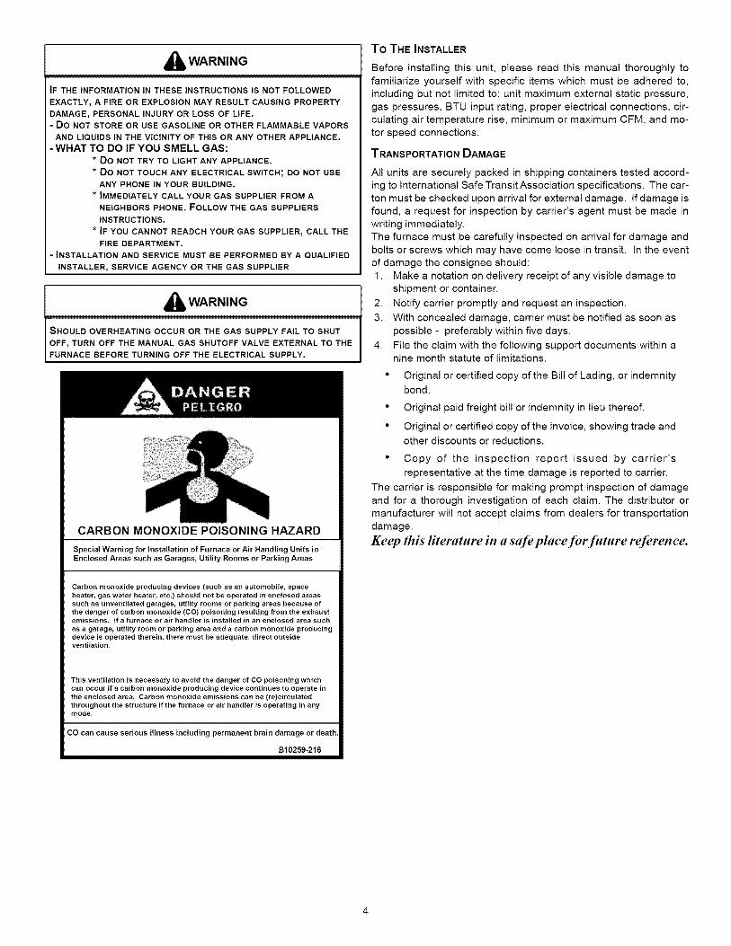
CARBON MONOXIDE POISONING HAZARD
SpecialWarningfor Installationof FurnaceorAir HandlingUnitsinEnclosedAreassuchas Garages,UtilityRoomsor ParkingAreas
Carbon monoxide producing devices (such as an automobile, spaceheater, gas water heater, etc.) should not be operated in enclosed areassuch as unventilated garages, utility rooms or parking areas because ofthe danger of carbon monoxide (CO) poisoning resulting from the exhaustemissions. If a furnace or air handler is installed in an enclosed area such
as a garage, utility room or parking area and a carbon monoxide producingdevice is operated therein, there must be adequate, direct outsideventilation.
This ventilation is necessary to avoid the danger of CO poisoning whichcan occur if a carbon monoxide producing device continues to operate inthe enclosed area. Carbon monoxide emissions can be (re)circulatedthroughout the structure if the furnace or air handler is operating in anymode.
CO can cause serious illness including permanent brain damage or death.
B10259-216
To THE INSTALLER
Before installing this unit, please read this manual thoroughly to
familiarize yourself with specific items which must be adhered to,
including but not limited to: unit maximum external static pressure,
gas pressures, BTU input rating, proper electrical connections, cir-culating air temperature rise, minimum or maximum CFM, and mo-
tor speed connections.
TRANSPORTATION DAMAGE
All units are securely packed in shipping containers tested accord-ing to International Safe Transit Association specifications. The car-
ton must be checked upon arrival for external damage. If damage is
found, a request for inspection by carrier's agent must be made in
writing immediately.
The furnace must be carefully inspected on arrival for damage andbolts or screws which may have come loose in transit. In the event
of damage the consignee should:
1. Make a notation on delivery receipt of any visible damage to
shipment or container.
2. Notify carrier promptly and request an inspection.
3. With concealed damage, carrier must be notified as soon as
possible - preferably within five days.
4. File the claim with the following support documents within anine month statute of limitations.
• Original or certified copy of the Bill of Lading, or indemnity
bond.
• Original paid freight bill or indemnity in lieu thereof.
• Original or certified copy of the invoice, showing trade and
other discounts or reductions.
• Copy of the inspection report issued by carrier's
representative at the time damage is reported to carrier.
The carrier is responsible for making prompt inspection of damage
and for a thorough investigation of each claim. The distributor or
manufacturer will not accept claims from dealers for transportation
damage.
Keep this literature in a safeplace for future reference.
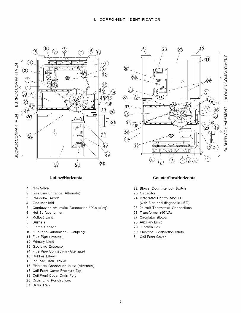
I. COMPONENT IDENTIFICATION
zw
I-
Oo
LUZ
£0
I--zwI-
oOn,"LU
O_J£0
/ / t--ZLLI
Z©0
w
©_Jrn
1-zw
o_
00
wz
rn
Upflow/Horizontal
1 Gas Valve
2 Gas Line Entrance (Alternate)
3 Pressure Switch
4 Gas Manifold
5 Combustion Air Intake Connection / "Coupling"
6 Hot Surface Igniter
7 Rollout Limit
8 Burners
9 Flame Sensor
10 Flue Pipe Connection / "Coupling"
11 Flue Pipe (internal)
12 Primary Limit
13 Gas Line Entrance
14 Flue Pipe Connection (Alternate)
15 Rubber Elbow
16 Induced Draft Blower
17 Electrical Connection Inlets (Alternate)
18 Coil Front Cover Pressure Tap
19 Coil Front Cover Drain Port
20 Drain Line Penetrations
21 Drain Trap
Counterflow/Horizontal
22 Blower Door Interlock Switch
23 Capacitor
24 Integrated Control Module
(with fuse and diagnostic LED)
25 24-Volt Thermostat Connections
26 Transformer (40 VA)
27 Circulator Blower
28 Auxiliary Limit
29 Junction Box
30 Electrical Connection Inlets
31 Coil Front Cover
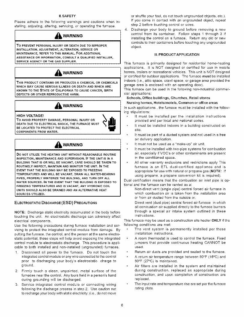
il.SAFETY
Please adhere to the following warnings and cautions when in-stalling, adjusting, altering, servicing, or operating the furnace.
,_ WARNING
TO PREVENT PERSONAL INJURY OR DEATH DUE TO IMPROPER
INSTALLATION_ADJUSTMENT_ ALTERATION, SERVICE ORMAINTENANCE, REFER TO THIS MANUAL. FOR ADDITIONAL
ASSISTANCE OR INFORMATION_ CONSULT A QUALIFIED INSTALLER,SERVICE AGENCY OR THE GAS SUPPLIER.
,_'_. WARNING
THIS PRODUCT CONTAINS OR PRODUCES A CHEMICAL OR CHEMICALSWHICH MAY CAUSE SERIOUS ILLNESS OR DEATH AND WHICH ARE
KNOWN TO THE STATE OF CALIFORNIA TO CAUSE CANCER_ BIRTHDEFECTS OR OTHER REPRODUCTIVE HARM.
,_ WARNING
HIGH VOLTAGE! _ _1_
To AVOID PROPERTY DAMAGEr PERSONAL INJURY ORDEATH DUE TO ELECTRICAL SHOCK_THE FURNACE MUSTBE LOCATED TO PROTECT THE ELECTRICALCOMPONENTS FROM WATER.
,_ WARNING
Do NOT UTILIZE THE HEATING UNIT WITHOUT REASONABLE ROUTINE
INSPECTION_ MAINTENANCE AND SUPERVISION. IF THE UNIT IS IN A
BUILDING THAT IS OR WILL BE VACANT_ CARE SHOULD BE TAKEN TO
ROUTINELY INSPECT_ MAINTAIN AND MONITOR THE UNIT. IN THE
EVENT THAT THE BUILDING MAY BE EXPOSED TO FREEZING
TEMPERATURES AND WILL BE VACANT, DRAIN ALL WATER-BEARING
PIPES, PROPERLY WINTERIZE THE BUILDING_ AND TURN OFF ALL
WATER SOURCES. IN THE EVENT THAT THE BUILDING IS EXPOSED TO
FREEZING TEMPERATURES AND IS VACANT, ANY HYDRONIC COIL
UNITS SHOULD ALSO BE DRAINED AND AN ALTERNATIVE HEAT
SOURCES UTILIZED.
ELECTROSTATIC DISCHARGE (ESD) PRECAUTIONS
NOTE: Discharge static electricity accumulated in the body beforetouching the unit. An electrostatic discharge can adversely affect
electrical components.
Use the following precautions during furnace installation and ser-vicing to protect the integrated control module from damage. By
putting the furnace, the control, and the person at the same electro-
static potential, these steps will help avoid exposing the integrated
control module to electrostatic discharge. This procedure is appli-
cable to both installed and non-installed (ungrounded) furnaces.
1. Disconnect all power to the furnace. Do not touch theintegrated control module or any wire connected to the control
prior to discharging your body's electrostatic charge to
ground.
2. Firmly touch a clean, unpainted, metal surface of the
furnaces near the control. Any tools held in a person's hand
during grounding will be discharged.
3. Service integrated control module or connecting wiring
following the discharge process in step 2. Use caution not
to recharge your body with static electricity; (i.e., do not move
4.
or shuffle your feet, do not touch ungrounded objects, etc.).
If you come in contact with an ungrounded object, repeat
step 2 before touching control or wires.
Discharge your body to ground before removing a new
control from its container. Follow steps 1 through 3 if
installing the control on a furnace. Return any old or new
controls to their containers before touching any ungroundedobject.
III. PRODUCT APPLICATION
This furnace is primarily designed for residential home-heating
applications. It is NOT designed or certified for use in mobile
homes, trailers or recreational vehicles. This unit is NOT designed
or certified for outdoor applications. The furnace must be installed
indoors (i.e., attic space, crawl space, or garage area provided thegarage area is enclosed with an operating door).
This furnace can be used in the following non-industrial commer-
cial applications:
Schools, Office buildings, Churches, Retail stores
Nursing homes, Hotels/motels, Common or office areas
In such applications, the furnace must be installed with the follow-
ing stipulations:
It must be installed per the installation instructions
provided and per local and national codes.
It must be installed indoors in a building constructed onsite.
It must be part of a ducted system and not used in a free
air delivery application.
It must not be used as a "make-up" air unit.
It must be installed with two-pipe systems for combustion
air, especially if VOC's or other contaminants are present
in the conditioned space.
All other warranty exclusions and restrictions apply This
furnace is an ETL dual-certified appliance and is
appropriate for use with natural or propane gas (NOTE: If
using propane, a propane conversion kit is required).
Dual certification means that the combustion air inlet pipe is op-tional and the furnace can be vented as a:
Non-direct vent (single pipe) central forced air furnace inwhich combustion air is taken from the installation area
or from air ducted from the outside or,
Direct vent (dual pipe) central forced air furnace in which
all combustion air supplied directly to the furnace burners
through a special air intake system outlined in theseinstructions.
This furnace may be used as a construction site heater ONLY if the
following conditions are met:
The vent system is permanently installed per theseinstallation instructions.
A room thermostat is used to control the furnace. Fixed
jumpers that provide continuous heating CANNOT beused.
Return air ducts are provided and sealed to the furnace.
A return air temperature range between 60°F (16°C) and80°F (27°C) is maintained.
Air filters are installed in the system and maintainedduring construction, replaced as appropriate during
construction, and upon completion of construction are
replaced.
The input rate and temperature rise are set per the furnace
rating plate.
100%outsideair is providedfor combustionairrequirementsduringconstruction.Temporaryductingcanbeused.NOTE:Donotconnectthetemporaryductdirectlytothefurnace.Theductmustbesizedaccordingto theinstructionsunderSection V, Combustion and Ventilation
Air Requirements, Section 5.3.3.
The furnace heat exchanger, components, duct system,
air filters and evaporator coils are thoroughly cleanedfollowing final construction clean up.
All furnace operating conditions (including ignition, inputrate, temperature rise and venting) are verified accordingto these installation instructions.
NOTE: The Commonwealth of Massachusetts requires that the
following additional requirements must also be met:
Gas furnaces must be installed by a licensed plumber orgas fitter.
A T-handle gas cock must be used.
If the unit is to be installed in an attic, the passageway to
and the service area around the unit must have flooring.
To ensure proper installation and operation, thoroughly read this
manual for specifics pertaining to the installation and application
of this product.
i_b WARNING
POSSIBLE PROPERTY DAMAGE, PERSONAL INJURY OR DEATH DUE TOFIRE_ EXPLOSION_ SMOKE_ SOOT_ CONDENSATION_ ELECTRICALSHOCK OR CARBON MONOXIDE MAY RESULT FROM IMPROPER
INSTALLATION, REPAIR, OPERATION_ OR MAINTENANCE OF THISPRODUCT.
I ,_ WARNINGTO PREVENT PERSONAL INJURY, PROPERTY DAMAGE OR DEATH DUETO FIRE, DO NOT INSTALL THIS FURNACE IN A MOBILE HOME_TRAILER OR RECREATIONAL VEHICLE.
To ensure proper furnace operation, install, operate and maintain
the furnace in accordance with these installation and operation
instructions, all local building codes and ordinances. In their ab-sence, follow the latest edition of the National Fuel Gas Code
(N FPA 54/ANSI Z223.1 ), and/or CAN/CSA B 149.1-05.1-05 Installa-tion Codes, local plumbing or waste water codes, and other appli-cable codes.
A copy of the National Fuel Gas Code (NFPA 54/ANSI Z223.1 ) can
be obtained from any of the following:American National Standards Institute
1430 BroadwayNewYork, NY 10018
National Fire Protection Association
1 Batterymarch Park
Quincy, MA 02269
CSA International
8501 East Pleasant Valley
Cleveland, OH 44131
A copy of the CAN/CSA B149.1-05.1-05 Installation Codes can alsobe obtained from:
CSA International178 Rexdale Boulevard
Etobicoke, Ontario, Canada M9W 1R3
The rated heating capacity of the furnace should be greater than or
equal to the total heat loss of the area to be heated. The total heat
loss should be calculated by an approved method or in accor-
dance with "ASHRAE Guide" or "Manual J-Load Calculations" pub-
lished by the Air Conditioning Contractors of America.
IV. LOCATION REQUIREMENTS & CONSIDERATIONS
GENERAL
,_ WARNING
TO PREVENT POSSIBLE EQUIPMENT DAMAGE_ PROPERTY DAMAGErPERSONAL INJURY OR DEATH_ THE FOLLOWING BULLET POINTS MUSTBE OBSERVED WHEN INSTALLING THE UNIT.
Follow the instructions listed below when selecting a furnace loca-tion. Refer also to the guidelines provided in Section V, Combus-
tion and Ventilation Air Requirements.
Centrally locate the furnace with respect to the proposed
or existing air distribution system.
Ensure the temperature of the return air entering thefurnace is between 55°F and 100°F when the furnace is
heating.
Provide provisions for venting combustion products
outdoors through a proper venting system. Specialconsideration should be given to vent/flue pipe routing
and combustion air intake pipe when applicable. Refer
to Section IX, Vent/Flue Pipe and Combustion Air Pipe -
Termination Locations for appropriate termination
locations and to determine if the piping system from
furnace to termination can be accomplished within theguidelines given. NOTE: The length of flue and/or
combustion air piping can be a limiting factor in thelocation of the furnace.
Locate the furnace so condensate flows downwards to
the drain. Do not locate the furnace or its condensate
drainage system in any area subject to below freezingtemperatures without proper freeze protection. Refer to
Section X, Condensate Drain Lines and Trap for furtherdetails.
Ensure adequate combustion air is available for the
furnace. Improper or insufficient combustion air can
expose building occupants to gas combustion productsthat could include carbon monoxide. Refer to Section V,
Combustion and Ventilation Air Requirements.
Set the furnace on a level floor to enable proper
condensate drainage. If the floor becomes wet or dampat times, place the furnace above the floor on a concrete
base sized approximately 1-1/2" larger than the base of
the furnace. Refer to the Section VII, Horizontal
Applications and Considerations for leveling of horizontalfurnaces.
Ensure upflow or horizontal furnaces are not installed
directly on carpeting, or any other combustible material.
The only combustible material allowed is wood.
A special accessory subbase must be used for upright
counterflow unit installations over any combustiblematerial (including wood). Refer to subbase instructions
for installation details. (NOTE: A subbase will not be
required if an air conditioning coil is located beneath the
furnace between the supply air opening and thecombustible floor.
Exposure to contaminated combustion air will result insafety and performance-related problems. Do not install
the furnace where the combustion air is exposed to the
followingsubstances:chlorinatedwaxesorcleanerschlorine-basedswimmingpoolchemicalswatersofteningchemicalsdeicingsaltsorchemicalscarbontetrachloridehalogentyperefrigerantscleaningsolutions(suchasperchloroethylene)printinginkspaintremoversvarnisheshydrochloricacidcementsandgluesantistaticfabricsoftenersforclothesdryersandmasonryacidwashingmaterials
Sealoffanon-direct vent furnace if it is installed near an
area frequently contaminated by any of the above
substances. This protects the non-direct vent furnacefrom airborne contaminants. To ensure that the
enclosed non-direct vent furnace has an adequate supplyof combustion air, vent from a nearby uncontaminatedroom or from outdoors. Refer to the Section V,
Combustion and Ventilation Air Requirements for details.
If the furnace is used in connection with a cooling unit,install the furnace upstream or in parallel with the cooling
unit. Premature heat exchanger failure will result if thecooling unit is placed ahead of the furnace.
If the furnace is installed in a residential garage, positionthe furnace so that the burners and ignition source are
located not less than 18 inches (457 mm) above the floor.Protect the furnace from physical damage by vehicles.
If the furnace is installed horizontally, the furnace accessdoors must be vertical so that the burners fire horizontally
into the heat exchanger. Do not install the unit with theaccess doors on the "up/top" or "down/bottom" side ofthe furnace.
CLEARANCES AND ACCESSIglLITY
Installations must adhere to the clearances to combustible mate-
rials to which this furnace has been design certified. The mini-
mum clearance information for this furnace is provided on the unit'sclearance label. These clearances must be permanently main-
tained. Clearances must also accommodate an installation's gas,electrical, and drain trap and drain line connections. If the alternate
vent/flue connection is used, additional clearance must be pro-vided to accommodate these connections. Refer to Section IX,
Vent Flue Pipe and Combustion Air Pipe for details. NOTE: Inaddition to the required clearances to combustible materials, aminimum of 24 inches service clearance must be available in front
of the unit.
TOP
SIDESIDESIDE
TOP
1o0I IBOTTOM
BOTTOM
Upftow Counterflow Horizontal
A furnace installed in a confined space (i.e., a closet or utility room)
must have two ventilation openings with a total minimum free areaof 0.25 square inches per 1,000 BTU/hr of furnace input rating.
Refer to the Specification Sheet applicable to your model for mini-mum clearances to combustible surfaces. One of the ventilation
openings must be within 12 inches of the top; the other opening
must be within 12 inches of the bottom of the confined space. In atypical construction, the clearance between the door and door frame
is usually adequate to satisfy this ventilation requirement.
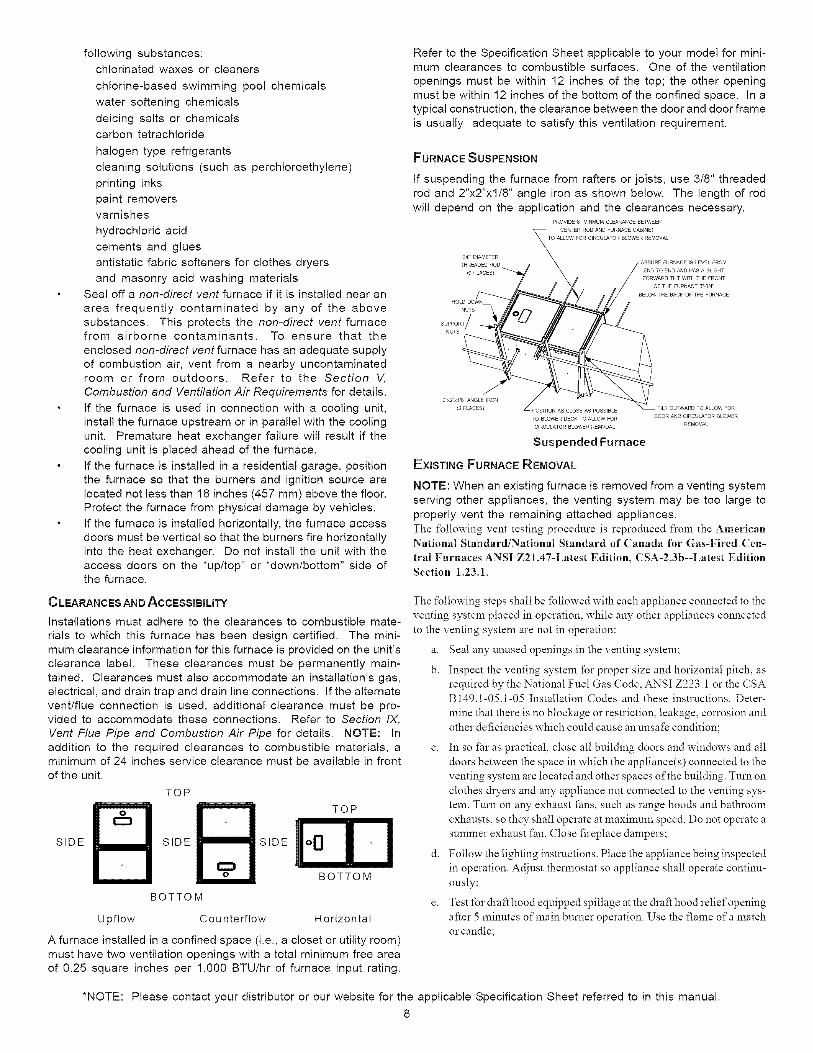
FURNACE SUSPENSION
If suspending the furnace from rafters or joists, use 3/8" threaded
rod and 2"x2"x1/8" angle iron as shown below. The length of rodwill depend on the application and the clearances necessary.
NOTE: When an existing furnace is removed from a venting systemserving other appliances, the venting system may be too large to
properly vent the remaining attached appliances.
The following vent testing procedure is reproduced from the American
National Standard/National Standard of Canada for Gas-Fired Cen-
tral Furnaces ANSI Z21.47-Latest Edition, CSA-2.3b--Latest Edition
Section 1.23.1.
The _bllowing steps shall be fbllowed with each appliance connected to the
venting system placed in operation, while any other appliances connected
to the venting system are not in operation:
a. Seal any unused openings in the venting system;
b. Inspect the venting system for proper size and horizontal pitch, as
required by the National Fuel Gas Code, ANSI Z223.1 or the CSAB 149.1-05.1-05 Installation Codes and these instructions. Deter-
mine that there is no blockage or restriction, leakage, corrosion and
other deficiencies which could cause an unsafe condition;
c. In so fhr as practical, close all building doors and windows and all
doors between the space in which the appliance(s) connected to the
venting system are located and other spaces of the building. Turn on
clothes &yers and any appliance not connected to the venting sys-
tem. Turn on any exhaust fhns, such as range hoods and bathroom
exhausts, so they shall operate at maximum speed. Do not operate a
summer exhaust fan. (;lose fireplace dampers;
d. Follow the lighting instrnctions. Place the appliance being inspected
in operation. Adjust thermostat so appliance shall operate continu-
ously;
e. Test lbr draft hood equipped spillage at the &afi hood relief opening
after 5 minutes of main burner operation. Use the flame of a match
or candle;
*NOTE: Please contact your distributor or our website for the applicable Specification Sheet referred to in this manual.
8
£ After it has been determined that each appliance connected to the
venting system properly vents when tested as outlined above, re-
turn doors, windows, exhaust _ans, fireplace dampers and any other
gas burning appliance to their previous conditions of use;
g. If improper venting is observed during any of the above tests, the
common venting system must be corrected.
Corrections must be in accordance with the latest edition of theNational Fuel Gas Code NFPA 54/ANSI Z223.1 and/or CSA B149.1-
05.1-05 Installation Codes.
If resizing is required on any portion of the venting system, use the
appropriate table in Appendix G in the latest edition of the NationalFuel Gas Code ANSI Z223.1 and/or CSA B149.1-05.1-05 Installa-tion Codes.
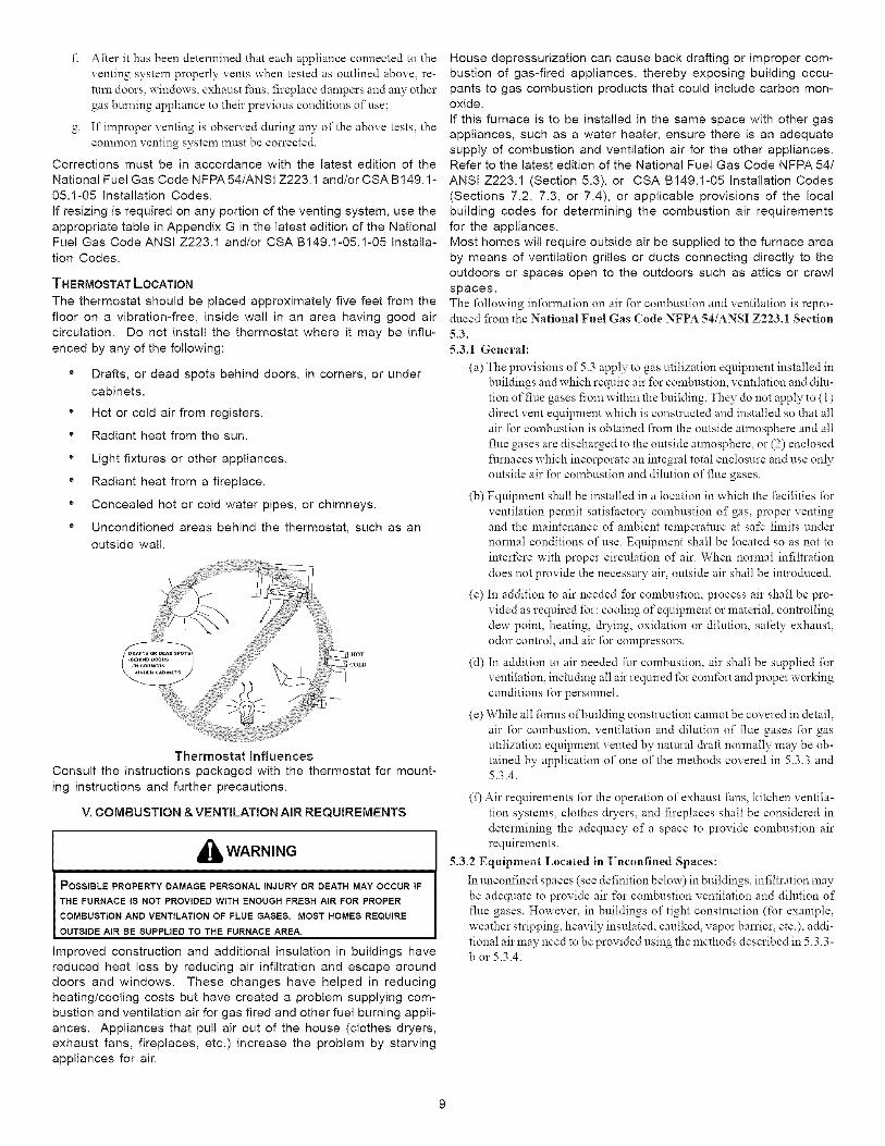
THERMOSTAT LOCATION
The thermostat should be placed approximately five feet from the
floor on a vibration-free, inside wall in an area having good air
circulation. Do not install the thermostat where it may be influ-
enced by any of the following:
" Drafts, or dead spots behind doors, in corners, or under
cabinets.
* Hot or cold air from registers.
" Radiant heat from the sun.
* Light fixtures or other appliances.
" Radiant heat from a fireplace.
* Concealed hot or cold water pipes, or chimneys.
" Unconditioned areas behind the thermostat, such as an
outside wall.
Thermostat Influences
Consult the instructions packaged with the thermostat for mount-
ing instructions and further precautions.
V. COMBUSTION & VENTILATION AIR REQUIREMENTS
,_ WARNING
POSSIBLE PROPERTY DAMAGE PERSONAL INJURY OR DEATH MAY OCCUR tF
THE FURNACE IS NOT PROVIDED WITH ENOUGH FRESH AIR FOR PROPER
COMBUSTION AND VENTILATION OF FLUE GASES. MOST HOMES REQUIRE
OUTSIDE AIR BE SUPPLIED TO THE FURNACE AREA.
Improved construction and additional insulation in buildings have
reduced heat loss by reducing air infiltration and escape around
doors and windows. These changes have helped in reducing
heating/cooling costs but have created a problem supplying com-
bustion and ventilation air for gas fired and other fuel burning appli-
ances. Appliances that pull air out of the house (clothes dryers,
exhaust fans, fireplaces, etc.) increase the problem by starving
appliances for air.
House depressurization can cause back drafting or improper com-
bustion of gas-fired appliances, thereby exposing building occu-pants to gas combustion products that could include carbon mon-oxide.
If this furnace is to be installed in the same space with other gasappliances, such as a water heater, ensure there is an adequate
supply of combustion and ventilation air for the other appliances.Refer to the latest edition of the National Fuel Gas Code NFPA 54/
ANSI Z223.1 (Section 5.3), or CSA B149.1-05 Installation Codes
(Sections 7.2, 7.3, or 7.4), or applicable provisions of the localbuilding codes for determining the combustion air requirements
for the appliances.Most homes will require outside air be supplied to the furnace area
by means of ventilation grilles or ducts connecting directly to the
outdoors or spaces open to the outdoors such as attics or crawl
spaces.The fbllowing infbnnation on air fbr combustion and ventilation is repro-duced fi'om the National Fuel Gas (?ode NFPA 54/ANSI Z223.1 Section
5.3.
5.3.1 General:
(a) The provisions of" 5.3 apply to gas utilization equipment installed in
buildings and which require air fbr combustion, ventilation and dilu-
tion of flue gases fi'om within the building. They do not apply to (1)
direct vent equipment which is constructed and installed so that all
air for combustion is obtained fi'om the outside atmosphere and all
flue gases are discharged to the outside atmosphere, or (2) enclosed
fhmaces which incorporate an integral total enclosure and use only
outside air for combustion and dilution of flue gases.
(b) Equipment shall be installed in a location in which the facilities for
ventilation permit satisfactory combustion of gas, proper venting
and the maintenance of ambient temperature at safe limits under
normal conditions of use. Equipment shall be located so as not to
interfere with proper circulation of air. When normal infihration
does not provide the necessary air, outside air shall be introduced.
(c) In addition to air needed fbr combustion, process air shall be pro-
vided as required fbr: cooling of equipment or material, controlling
dew point, heating, &ying, oxidation or dilution, safety exhaust,
odor control, and air fbr compressors.
(d) In addition to air needed for combustion, air shall be supplied fbr
ventilation, including all air required for comfort and proper working
conditions for personneh
(e) While all fbmas of building construction cannot be covered in detail,
air fbr combustion, ventilation and dilution of flue gases fbr gas
utilization equipment vented by natural &aft nonnally may be ob-
tained by application of one of the methods covered in 5.3.3 and5.3.4.
(f) Air requirements for the operation of exhaust fans, kitchen ventila-
tion systems, clothes &yers, and fireplaces shall be considered in
determining the adequacy of a space to provide combustion air
requirements.
5.3.2 Equipment Located in [ nconfined Spaces:
In unconfined spaces (see definition below) in buildings, infihration may
be adequate to provide air for combustion ventilation and dilution of
flue gases. However, in buildings of tight construction (for example,
weather stripping, heavily insulated, caulked, vapor barrier, etc.), addi-
tional air may need to be provided using the methods described in 5.3.3-b or 5.3.4.
Space,Unconfined.Forpurposesofthis(?ode,aspacewhosevohuneisnotlessthan50cubicf_etper1,000BTUperhouroftheaggregateinputratingofallappliancesinstalledinthatspace.Roomscommunicatingdirectlywiththespaceinwhichtheappliancesareinstalledthroughopeningsnotfurnishedwithdoors,areconsideredapartoftheunconfinedspace.
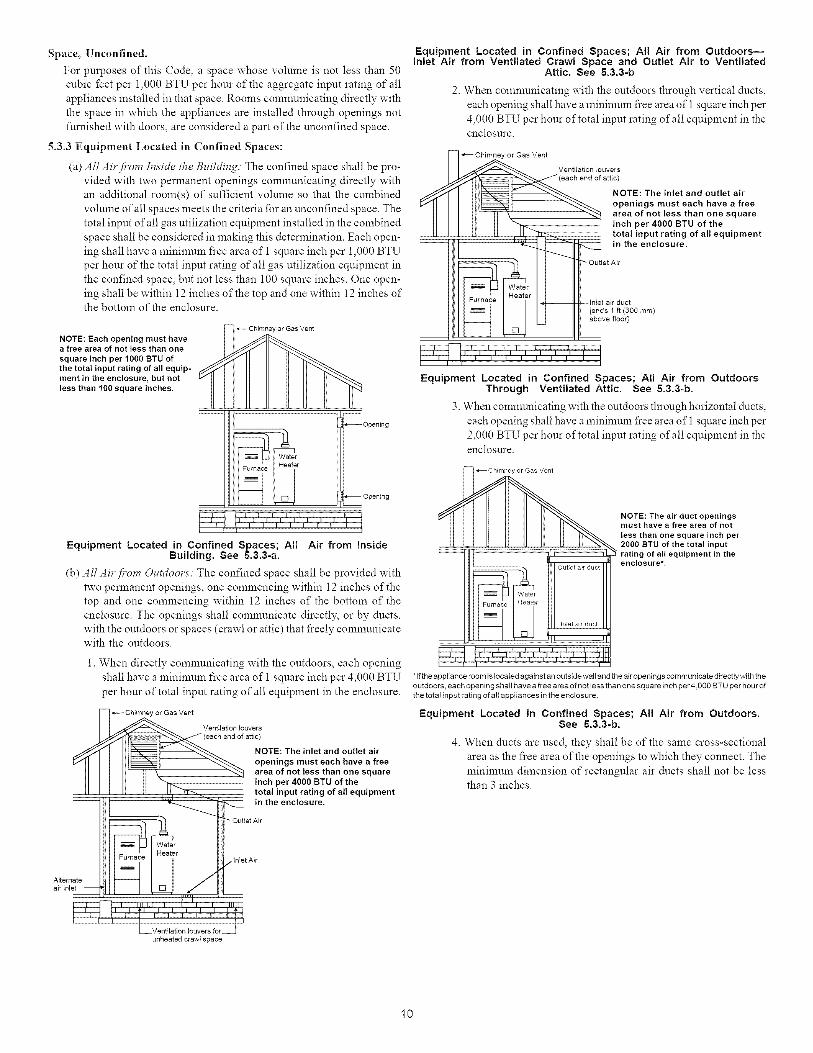
5.3.3EquipmentLocated in Confined Spaces:
(a) All Air from ln,_icle the Building: The confined space shall be pro-
vided with two permanent openings comnmnicating directly with
an additional room(s) of" sufficient volume so that the combined
volume of all spaces meets the criteria for an unconfined space. The
total input of all gas utilization equipment installed in the combined
space shall be considered in making this determination. Each open-
ing shall have a minimum fi'ee area of I square inch per 1,000 BTU
per hour of the total input rating of all gas utilization equipment in
the confined space, but not less than 100 square inches. One open-
ing shall be within 12 inches of the top and one within 12 inches ofthe bottom of the enclosure.
NOTE: Each opening must havea free area of not less than one
square inch per 1000 BTU of
the total input rating of all equip-ment in the enclosure, but not
less than 100 square inches.
Chimney or Gas Vent
__ _Opening
i Water r
Opening
tl I I I I I I I
Equipment Located in Confined Spaces; Al! Air from InsideBuilding. See &3.3-a.
(b) All Air from OuMoors: The confined space shall be provided with
two permanent openings, one commencing within 12 inches of the
top and one commencing within 12 inches of the bottom of the
enclosure. The openings shall comnmnicate directly, or by ducts,
with the outdoors or spaces (crawl or attic) that fi'eely communicatewith the outdoors.
l. When directly communicating with the outdoors, each opening
shall have a mininmm free area of 1 square inch per 4,000 BTU
per hour of total input rating of all equipment in the enclosure.
Chimney or Gas Vent
Ventilation louvers
NOTE: The inlet and outlet air
openings must each have a freearea of not tess than one square
inch per 4000 BTU of thetotal input rating of all equipmentin the enclosure.
Outlet Air
Equipment Located in Confined Spaces; AH Air from Outdoors--Inlet Air from Ventilated Crawl Space and Outlet Air to Ventilated
Attic. See 5.3.3-b
2. When communicating with the outdoors through vertical ducts,
each opening shall have a mininmm fi'ee area of 1 square inch per
4,000 BTU per hour of total input rating of all equipment in theenclosure.
_Chimney or Gas Vent
Ventilation louvers
_)/eatch end of attic)
_'J1" I III_N;;;;_I- "_. NOTE:Theinletandoutletair_"ql II Itl_t _ openingsmusteachhaveafree
IIII II' II \2 _",,_ area of not less than one squareII I I I1 II _ inch per 4000 BTU of the
II I I II It , II''_ "_ totalmputratmgofaltequlpment
I,,,,_ _ _ in the enclosure.
_ --OutletA0
Wati rHeater
Furnace --tNet air duct
[ends 1 ft (300 ram)
_-1 D_ ab°ve fl°°r]
Equipment Located in Confined Spaces; All Air from OutdoorsThrough Ventilated Attic. See 5.3.3-b.
3. When communicating with the outdoors through horizontal ducts,
each opening shall have a mininmm fi'ee area of 1 square inch per
2,000 BTU per hour of total input rating of all equipment in theenclosure.
outlet ail duct
h_et air duct
ql
NOTE: The air duct openingsmust have a free area of not
less than one square inch per2000 BTU of the total inputrating of all equipment in theenclosure*.
*If the appliance room is located against an outside wall and the air openings comm unicate directly with theoutdoors, each opening shall have a free area of not less than one square inch per4,g0o BTU per hour of
the total input rating of all appliances in the enclosure
Equipment Located in Confined Spaces; All Air from Outdoors.See 5.3.3-b.
4. When ducts are used, they shall be of the same cross-sectional
area as the fi'ee area of the openings to which they connect. The
minimum dimension of rectangular air ducts shall not be lessthan 3 inches.
Alternate
air inlet
Inlet Air
Ventilation louvers for
unheated crawl space
10
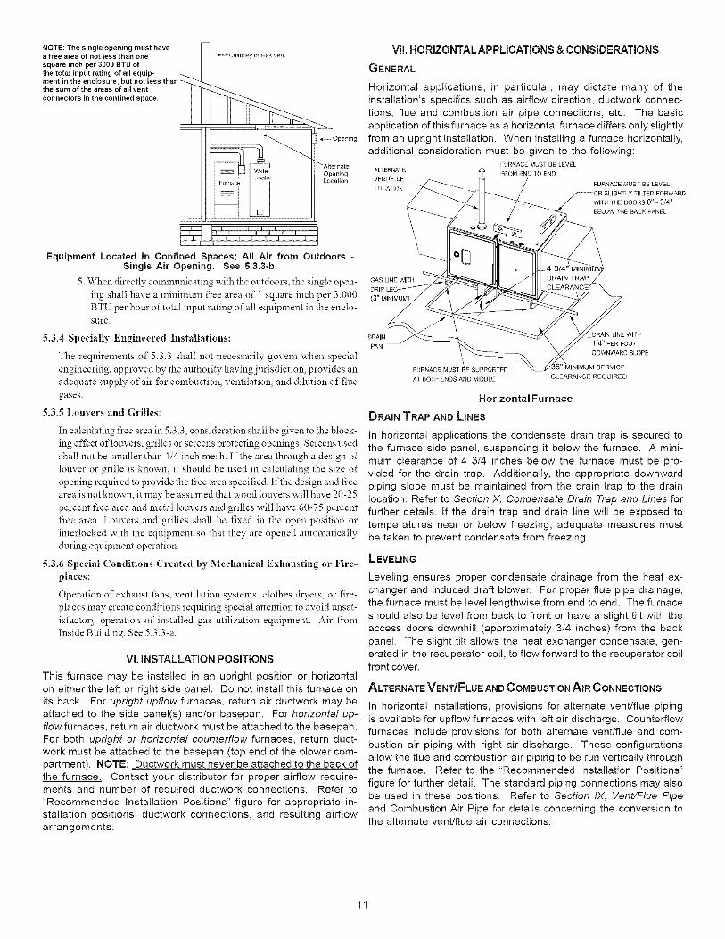
NOTE: The single opening must havea free area of not less than one
square inch per 3000 BTU ofthe total input rating of all equip-ment in the enclosure, but notthe sum of the areas of all vent
connectors in the confined space.
Cl_imney or Gas Vent
_-- Opening
"AlternateOpeningLocation
[ t I I I t I IF I _ I I I
Equipment Located in Confined Spaces; All Air from Outdoors -Singme Air Opening. See 5.3.3-b.
5. When directly communicating with the outdoors, the single open-
ing shall have a minimum fi'ee area of 1 square inch per 3,000
BTU per hour of total input rating of all equipment in the enclo-
sure.
5.3.4 Specially Engineered Installations:
The requirements of 5.3.3 shall not necessarily govern when special
engineering, approved by the authority having jurisdiction, provides an
adequate supply of air fbr combustion, ventilation, and dihttion of flue
gases.
5.3.5 Louvers and Grilles:
In calculating fi'ee area in 5.3.3, consideration shall be given to the block-
ing effect of louvers, grilles or screens protecting openings. Screens used
shall not be smaller than 1/4 inch mesh. If the area through a design of
louver or grille is known, it should be used in calculating the size of
opening required to provide the fi'ee area specified. If the design and fi'ee
area is not known, it may be assumed that wood louvers will have 20-25
percent free area and metal louvers and grilles will have 60-75 percent
fi'ee area. Louvers and grilles shall be fixed in the open position or
interlocked with the equipment so that they are opened atttomatically
during equipment operation.
5.3.6 Special Conditions Created by Mechanical Exhausting or Fire-
places:
Operation of exhaust _ans, ventilation systems, clothes &yers, or fire-places may create conditions requiring @ecial attention to avoid unsat-
isfhctory operation of installed gas utilization equipment. Air from
Inside Building. See 5.3.3-a.
Vl. INSTALLATION POSITIONS
This furnace may be installed in an upright position or horizontal
on either the left or right side panel. Do not install this furnace on
its back. For upright upflow furnaces, return air ductwork may beattached to the side panel(s) and/or basepan. For horizontal up-
flowfurnaces, return air ductwork must be attached to the basepan.
For both upright or horizontal eounterflow furnaces, return duct-work must be attached to the basepan (top end of the blower com-
partment). NOTE: Ductwork must never be attached to the back ofthe furnace. Contact your distributor for proper airflow require-
ments and number of required ductwork connections. Refer to
"Recommended Installation Positions" figure for appropriate in-stallation positions, ductwork connections, and resulting airflow
arrangements.
VII. HORIZONTALAPPLICATIONS & CONSIDERATIONS
GENERAL
Horizontal applications, in particular, may dictate many of theinstallation's specifics such as airflow direction, ductwork connec-
tions, flue and combustion air pipe connections, etc. The basic
application of this furnace as a horizontal furnace differs only slightly
from an upright installation. When installing a furnace horizontally,
additional consideration must be given to the following:FURNACE MUST BE LEVEL
ALTERNATE z_ FROM END TO ENDVENT/FLUE
LOCATION FURNACE MUST BE LEVEL
WiTH mE DOORS0" - 3/4"
BELOW THE BACK PANEL
GAS LINE WITH
(3" MINIMUM)
DRAIN DRAIN LINE WITH
PAN I/4" PER FOOT
DOWNWARD SLOPE
FURNACE MUST BE SUPPORTED
Ar BOIH ENDS AND MIDDLECLEARANCE REQUIRED
Horizontal Furnace
DRAIN TRAP AND LINES
In horizontal applications the condensate drain trap is secured to
the furnace side panel, suspending it below the furnace. A mini-
mum clearance of 4 3/4 inches below the furnace must be pro-
vided for the drain trap. Additionally, the appropriate downwardpiping slope must be maintained from the drain trap to the drain
location. Refer to Section X, Condensate Drain Trap and Lines for
further details. [f the drain trap and drain line will be exposed to
temperatures near or below freezing, adequate measures mustbe taken to prevent condensate from freezing.
LEVELING
Leveling ensures proper condensate drainage from the heat ex-
changer and induced draft blower. For proper flue pipe drainage,the furnace must be level lengthwise from end to end. The furnace
should also be level from back to front or have a slight tilt with the
access doors downhill (approximately 3/4 inches) from the back
panel. The slight tilt allows the heat exchanger condensate, gen-
erated in the recuperator coil, to flow forward to the recuperator coilfront cover.
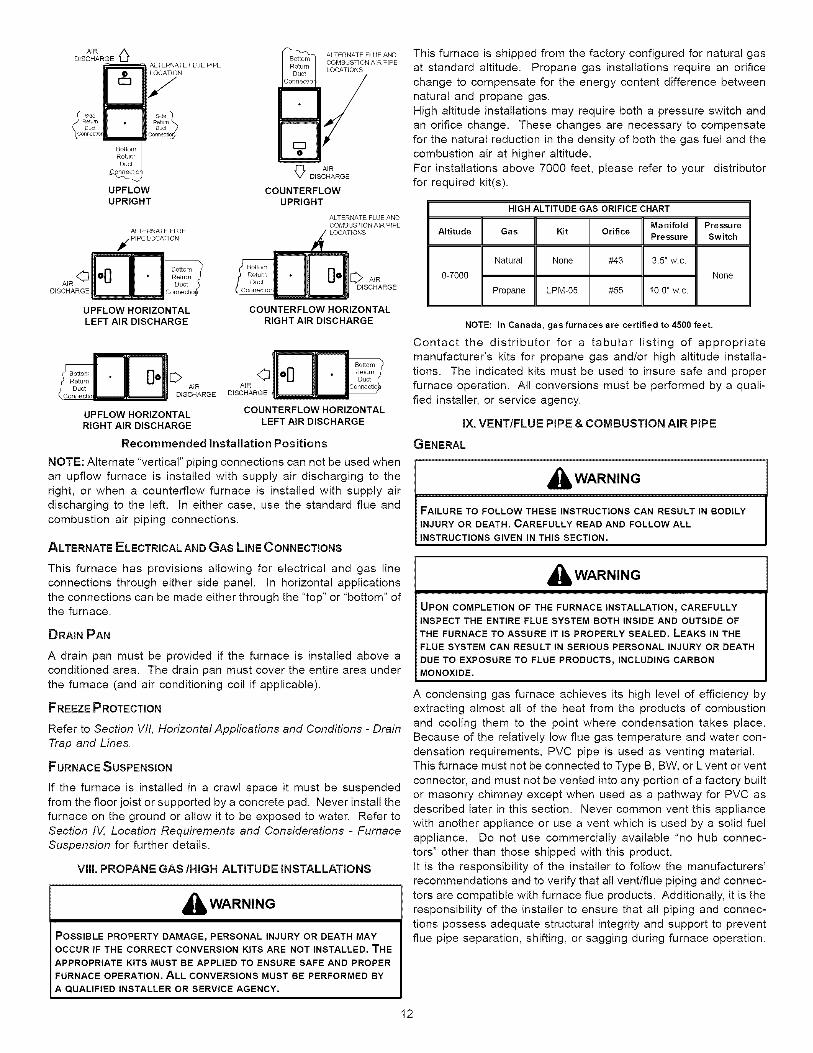
ALTERNATE VENT/FLUE AND COMBUSTION AIR CONNECTIONS
In horizontal installations, provisions for alternate vent/flue piping
is available for upflow furnaces with left air discharge. Counterflowfurnaces include provisions for both alternate vent/flue and com-
bustion air piping with right air discharge. These configurations
allow the flue and combustion air piping to be run vertically throughthe furnace. Refer to the "Recommended Installation Positions"
figure for further detail. The standard piping connections may also
be used in these positions. Refer to Section IX, Vent/Flue Pipe
and Combustion Air Pipe for details concerning the conversion tothe alternate vent/flue air connections.
AIRDISCHARGE '_
UPFLOWUPRIGHT
ALTERNATE FLUE
,_ PIPE LOCATION
AIR <_
UPFLOW HORIZONTALLEFT AIR DISCHARGE
ALTERNATE FLUE AND
_ AIRDISCHARGE
COUNTERFLOWUPRIGHT
ALTERNATE FLUE AND
COMBUSTION AIR PIPE
[_ AIRDISCHARGE
COUNTERFLOW HORIZONTAL
RIGHT AIR DISCHARGE
HI I1_ DISCHARGE DISCHARGE
UPFLOW HORIZONTAL COUNTERFLOW HORIZONTALRIGHT AIR DISCHARGE LEFT AIR DISCHARGE
Recommended Installation Positions
NOTE: Alternate "vertical" piping connections can not be used whenan upflow furnace is installed with supply air discharging to the
right, or when a counterflow furnace is installed with supply air
discharging to the left. In either case, use the standard flue and
combustion air piping connections.
ALTERNATE ELECTRICAL AND GAS LINE CONNECTIONS
This furnace is shipped from the factory configured for natural gas
at standard altitude. Propane gas installations require an orifice
change to compensate for the energy content difference between
natural and propane gas.
High altitude installations may require both a pressure switch andan orifice change. These changes are necessary to compensate
for the natural reduction in the density of both the gas fuel and the
combustion air at higher altitude.
For installations above 7000 feet, please refer to your distributorfor required kit(s).
HIGH ALTITUDE GAS ORIFICE CHART
Manifold PressureAltitude Gas Kit Orifice Pressure Switch
Natural None #43 3.5" w.c.
0-7000 None
Propane LPM-05 #55 10.0" w.c.
NOTE: In Canada, gas furnaces are certified to 4500 feet.
Contact the distributor for a tabular listing of appropriate
manufacturer's kits for propane gas and/or high altitude installa-tions. The indicated kits must be used to insure safe and proper
furnace operation. All conversions must be performed by a quali-
fied installer, or service agency.
IX. VENT/FLUE PiPE & COMBUSTION AiR PIPE
GENERAL
I_WARNING
FAILURE TO FOLLOW THESE INSTRUCTIONS CAN RESULT IN BODILYINJURY OR DEATH. CAREFULLY READ AND FOLLOW ALLINSTRUCTIONS GIVEN IN THIS SECTION.
I_WARNINGThis furnace has provisions allowing for electrical and gas lineconnections through either side panel. In horizontal applications
the connections can be made either through the "top" or "bottom" ofthe furnace.
DRAIN PAN
A drain pan must be provided if the furnace is installed above a
conditioned area. The drain pan must cover the entire area under
the furnace (and air conditioning coil if applicable).
FREEZE PROTECTION
Refer to Section VII, Horizontal Applications and Conditions - Drain
Trap end Lines.
FURNACE SUSPENSION
If the furnace is installed in a crawl space it must be suspendedfrom the floor joist or supported by a concrete pad. Never install the
furnace on the ground or allow it to be exposed to water. Refer to
Section IV, Location Requirements and Considerations - Furnace
Suspension for further details.
VIII. PROPANE GAS/HIGH ALTITUDE INSTALLATIONS
i_ WARNING
POSSIBLE PROPERTY DAMAGE, PERSONAL INJURY OR DEATH MAYOCCUR IF THE CORRECT CONVERSION KITS ARE NOT INSTALLED. THEAPPROPRIATE KITS MUST BE APPLIED TO ENSURE SAFE AND PROPERFURNACE OPERATION. ALL CONVERSIONS MUST BE PERFORMED BY
A QUALIFIED INSTALLER OR SERVICE AGENCY.
UPON COMPLETION OF THE FURNACE INSTALLATION, CAREFULLY
INSPECT THE ENTIRE FLUE SYSTEM BOTH INSIDE AND OUTSIDE OF
THE FURNACE TO ASSURE IT IS PROPERLY SEALED. LEAKS IN THE
FLUE SYSTEM CAN RESULT IN SERIOUS PERSONAL INJURY OR DEATH
DUE TO EXPOSURE TO FLUE PRODUCTS_ INCLUDING CARBON
MONOXIDE.
A condensing gas furnace achieves its high level of efficiency by
extracting almost all of the heat from the products of combustion
and cooling them to the point where condensation takes place.Because of the relatively low flue gas temperature and water con-
densation requirements, PVC pipe is used as venting material.
This furnace must not be connected to Type B, BW, or L vent or vent
connector, and must not be vented into any portion of a factory built
or masonry chimney except when used as a pathway for PVC as
described later in this section. Never common vent this appliancewith another appliance or use a vent which is used by a solid fuel
appliance. Do not use commercially available "no hub connec-
tors" other than those shipped with this product.
It is the responsibility of the installer to follow the manufacturers'recommendations and to verify that all vent/flue piping and connec-
tors are compatible with furnace flue products. Additionally, it is the
responsibility of the installer to ensure that all piping and connec-
tions possess adequate structural integrity and support to prevent
flue pipe separation, shifting, or sagging during furnace operation.
12
DUAL CERTIFICATION: NoN=DIRECTIDIRECT VENT
This furnace is dual certified and may be installed as a non-direct
vent (single pipe) or direct vent (dual pipe) appliance. A non-direct
vent installation requires only a vent/flue pipe, while a direct vent
installation requires both a vent/flue pipe and a combustion airintake pipe. Refer to the appropriate section for details concerning
piping size, length, number of elbows, furnace connections, andterminations.
MATERIALS AND JOINING M ETHODS
,_ WARNING
TO AVOID BODILY INJURY_ FIRE OR EXPLOSION_ SOLVENT CEMENTSMUST BE KEPT AWAY FROM ALL IGNITION SOURCES (I,E._ SPARKS_OPEN FLAMES_AND EXCESSIVE HEAT) AS THEY ARE COMBUSTIBLELIQUIDS. AVOID BREATHING CEMENT VAPORS OR CONTACT WITHSKIN AND/OR EYES.
Two- or three-inch nominal diameter PVC Schedule 40 pipe meet-
ing ASTM D1785, PVC primer meeting ASTM F656, and PVC sol-
vent cement meeting ASTM D2564 specifications must be used.Fittings must be DWV type fittings meeting ASTM D2665 and ASTM
D3311. Carefully follow the manufacturer's instructions for cutting,
cleaning, and solvent cementing of PVC.
As an alternative to PVC pipe, primer, solvent cement, and fittings,
ABS materials which are in compliance with the following specifi-cations may be used. Two-or-three-inch ABS Schedule 40 pipe
must meet ASTM D1527 and, if used in Canada, must be CSA
listed. Solvent cement for ABS to ABS joints must meet ASTM
D2235 and, if used in Canada, must be CSA listed. The solvent
cement for the PVC to ABS transition joint must meet ASTM D3138.Fittings must be DWV type fittings meeting ASTM D2661 and ASTM
D3311 and, if used in Canada, must be CSA listed. Carefully
follow the pipe manufacturers' instructions for cutting, cleaning,
and solvent cementing PVC and/or ABS.All 90 ° elbows must be medium radius (1/4 bend DWV) or long
radius (Long sweep 1/4 bend DWV) types conforming to ASTM
D3311. A medium radius (1/4 bend DWV) elbow measures 3 1/
16" minimum from the plane of one opening to the centerline of the
other opening for 2" diameter pipe, and 4 9/16" minimum for 3"
pipe.
PROPER VENTIFLUE AND COMBUSTION A_R PIPING PRACTICES
Adhere to these instructions to ensure safe and proper furnace
performance. The length, diameter, and number of elbows of the
vent/flue pipe and combustion air pipe (when applicable) affectsthe performance of the furnace and must be carefully sized. All
piping must be installed in accordance with local codes and theseinstructions.
Piping must be adequately secured and supported to prohibit sag-ging, joint separation, and/or detachment from the furnace. Hori-
zontal runs of vent/flue piping must be supported every three to five
feet and must maintain a 1/4 inch per foot downward slope, back
towards the furnace, to properly return condensate to the furnace's
drain system. Allowances should be made for minor expansion
and contraction due to temperature variations. For this reason,particular care must be taken to secure piping when a long run is
followed by a short offset of less than 40 inches.
TERMINATION LOCATIONS
NOTES: Refer to Section IV, Location Requirements andConsiderations for combustion air contaminant restrictions.
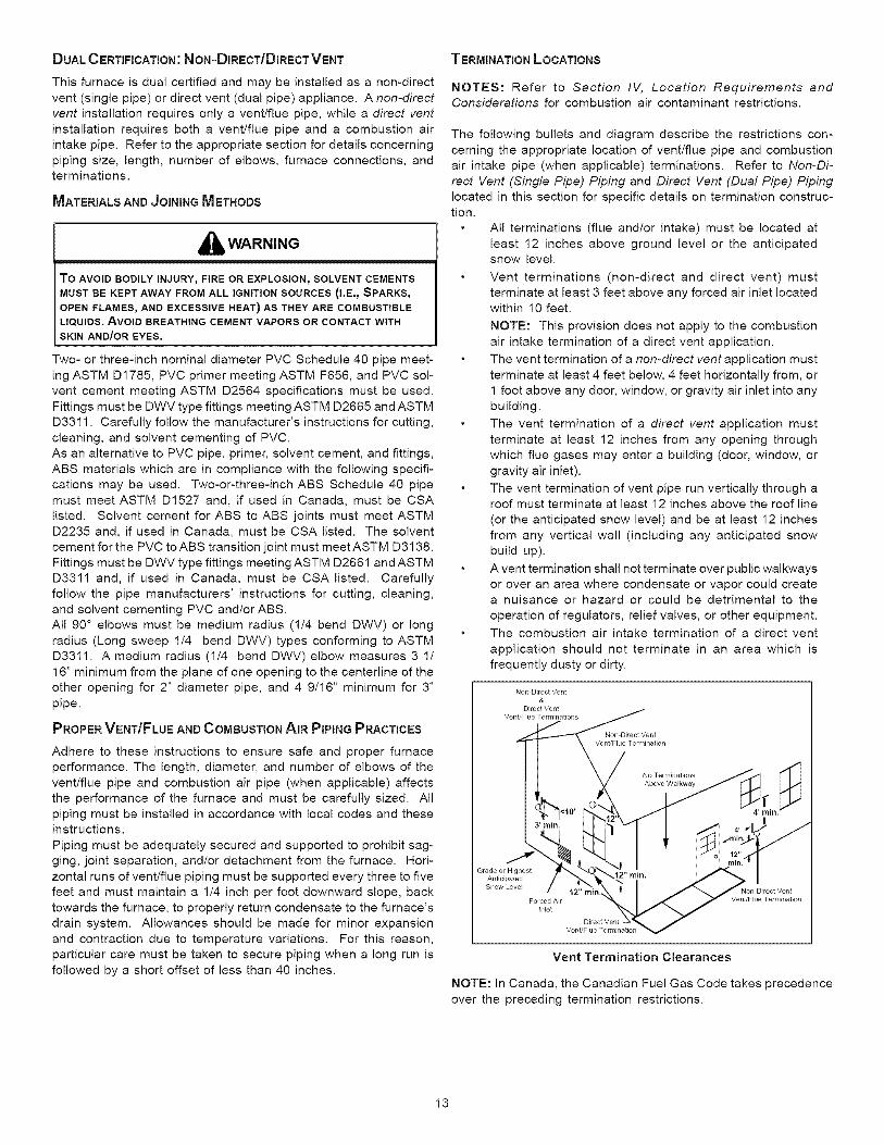
The following bullets and diagram describe the restrictions con-
cerning the appropriate location of vent/flue pipe and combustion
air intake pipe (when applicable) terminations. Refer to Non-Di-
rect Vent (Single Pipe) Piping and Direct Vent (Dual Pipe) Pipinglocated in this section for specific details on termination construc-tion.
All terminations (flue and/or intake) must be located at
least 12 inches above ground level or the anticipatedsnow level.
Vent terminations (non-direct and direct vent) must
terminate at least 3 feet above any forced air inlet locatedwithin 10 feet.
NOTE: This provision does not apply to the combustion
air intake termination of a direct vent application.
The vent termination of a non-direct vent application must
terminate at least 4 feet below, 4 feet horizontally from, or1 foot above any door, window, or gravity air inlet into any
building.
The vent termination of a direct vent application must
terminate at least 12 inches from any opening through
which flue gases may enter a building (door, window, or
gravity air inlet).
The vent termination of vent pipe run vertically through aroof must terminate at least 12 inches above the roof line
(or the anticipated snow level) and be at least 12 inchesfrom any vertical wall (including any anticipated snow
build up).
A vent termination shall not terminate over public walkwaysor over an area where condensate or vapor could createa nuisance or hazard or could be detrimental to the
operation of regulators, relief valves, or other equipment.
The combustion air intake termination of a direct vent
application should not terminate in an area which is
frequently dusty or dirty.
Non Direct Vent
&
Grade or Highest
Anticipated
Vent Termination Clearances
NOTE: In Canada, the Canadian Fuel Gas Code takes precedence
over the preceding termination restrictions.
13
CANADIAN VENTING REQUIREMENTS
IIn Canada, venting must conform to the requirements of the cur-
rent CAN/CSA-B149.1-05 Installation Code. Use only CSA-listed,
ULC-$636 compliant two- or three-inch diameter PVC crABS pipe,
solvent cement, and fittings throughout. The certified piping shouldbe clearly marked with the ULC Std "$636" on the pipe and
fittings.Carefully follow the pipe manufacturers' instructions for cut-
ting, cleaning, and solvent cementing PVC and/or ABS.
The vent can be run through an existing unused chimney provided
the space between the vent pipe and the chimney is insulated andclosed with a weather-tight, corrosion-resistant flashing.
STANDARD FURNACE CONNECTIONS
It is the responsibility of the installer to ensure that the piping
connections to the furnace are secure, airtight, and adequatelysupported.
As shipped, attachment "couplings" for vent/flue and combustion
air intake pipe connections are provided on the furnace's top cover
(upflow) or basepan (counterflow). To use the standard connec-tions, field supplied vent/flue pipe and combustion air intake pipe
(when applicable) should be secured directly to the furnace atthese locations.
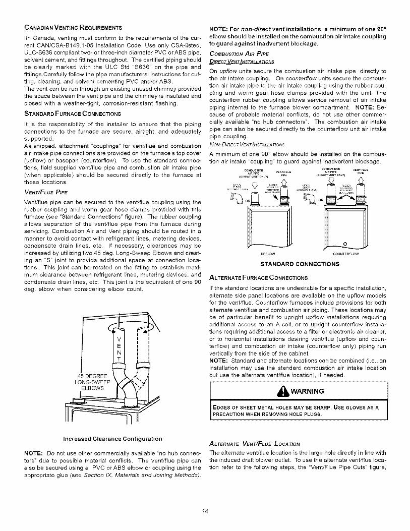
VENT/FLuEPIPE
Vent/flue pipe can be secured to the vent/flue coupling using the
rubber coupling and worm gear hose clamps provided with this
furnace (see "Standard Connections" figure). The rubber couplingallows separation of the vent/flue pipe from the furnace during
servicing. Combustion Air and Vent piping should be routed in a
manner to avoid contact with refrigerant lines, metering devices,
condensate drain lines, etc. if necessary, clearances may be
increased by utilizing two 45 deg. Long-Sweep Elbows and creat-ing an "S" joint to provide additional space at connection loca-
tions. This joint can be rotated on the fitting to establish maxi-
mum clearance between refrigerant lines, metering devices, and
condensate drain lines, etc. This joint is the equivalent of one 90
deg. elbow when considering elbow count.
NOTE: For non=direct vent installations, a minimum of one 90 °
elbow should be installed on the combustion air intake couplingto guard against inadvertent blockage.
COMBUSTIONAIR PIPEDIRECT VENT INS TALLA TtONS
On upflow units secure the combustion air intake pipe directly to
the air intake coupling. On eounterflow units secure the combus-
tion air intake pipe to the air intake coupling using the rubber cou-
pling and worm gear hose clamps provided with the unit. The
counterflow rubber coupling allows service removal of air intake
piping internal to the furnace blower compartment. NOTE: Be-cause of probable material conflicts, do not use other commer-
cially available "no hub connectors". The combustion air intake
pipe can also be secured directly to the counterflow unit air intake
pipe coupling.
NoN-DIRECTVENT INSTALLATIONS
A minimum of one 90 ° elbow should be installed on the combus-
tion air intake "coupling" to guard against inadvertent blockage.
COMBUSTION COMBUSTION VENWFLUEAIR P_PE VENTIFLUE AiR P_PE P_PE
(O_RECTVENT ONLY) P_PE (DIRECT VENT ONLY)
EBOW COUPLING ELBOW
(NO DIRECT EFJTI _ITH V_RM [NO_D_ECT E T]
.:._. : _.... ,
UPFLOW COUNTERFLOW
STANDARD CONNECTIONS
ALTERNATE FURNACE CONNECTIONS
If the standard locations are undesirable for a specific installation,
alternate side panel locations are available on the upflow models
for the vent/flue. Counterflow furnaces include provisions for both
alternate vent/flue and combustion air piping. These locations maybe of particular benefit to upright upflow installations requiring
additional access to an A coil, or to upright counterflow installa-
tions requiring additional access to a filter or electronic air cleaner,
or to horizontal installations desiring vent/flue (upflow and coun-terflow) and combustion air intake (counterflow only) piping run
vertically from the side of the cabinet.
NOTE: Standard and alternate locations can be combined (i.e., an
installation may use the standard combustion air intake location
but use the alternate vent/flue location), if needed.
EDGES OF SHEET METAL HOLES MAY BE SHARP. USE GLOVES AS A
PRECAUT ON WHEN REMOV NG HOLE PLUGS.
increased Clearance Configuration
NOTE: Do not use other commercially available "no hub connec-
tors" due to possible material conflicts. The vent/flue pipe can
also be secured using a PVC or ABS elbow or coupling using the
appropriate glue (see Section IX, Materials and Joining Methods).
ALTERNATE VENT/FLuE LOCATION
The alternate vent/flue location is the large hole directly in line withthe induced draft blower outlet. To use the alternate vent/flue loca-
tion refer to the following steps, the "Vent/Flue Pipe Cuts" figure,
14
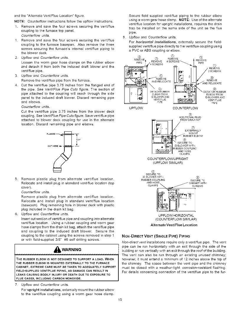
and the "Alternate Vent/Flue Location" figure.
NOTE: Counterflow instructions follow the upflow instructions.
1. Remove and save the four screws securing the vent/fluecoupling to the furnace top panel.
Counterflow units.
1. Remove and save the four screws securing the vent/flue
coupling to the furnace basepan. Also remove the three
screws securing the furnace's internal vent/flue piping tothe blower deck.
2. Upflew and Counterflew units.
Loosen the worm gear hose clamps on the rubber elbowand detach it from both the induced draft blower and the
vent/flue pipe.
3. Upflew and Counterflew units.
Remove the vent/flue pipe from the furnace.
4. Cut the vent/flue pipe 3.75 inches from the flanged end of
the pipe. See Vent/Flue Pipe Cuts figure. The section of
pipe attached to the coupling will reach through the sidepanel to the induced draft blower. Discard remaining pipeand elbows.
Counterflow units.
Cut the vent/flue pipe 3.75 inches from the blower deck
coupling. See Vent/Flue Pipe Cuts figure. Save vent/flue pipe
attached to blower deck coupling for use in the alternate
location. Discard remaining pipe and elbows.
5. Remove plastic plug from alternate vent/flue location.
Relocate and install plug in standard vent/flue location (topcover).
Counterflow units.
Remove plastic plug from alternate vent/flue location.
Relocate and install plug in standard vent/flue location
(basepan). Plug remaining hole in blower deck with plasticplug included in the drain kit bag.
6. Upflew and Counterflew units.
Insert cut section of vent/flue pipe and coupling into alternate
vent/flue location. Using a rubber coupling and worm gearhose clamps from the drain kit bag, attach the vent/flue pipe
and coupling to the induced draft blower. Secure the
coupling to the cabinet using the screws removed in step 1or with field-supplied 3/8" #8 self drilling screws.
,_ WARNING
THE RUBBER ELBOW IS NOT DESIGNED TO SUPPORT A LOAD. WHEN
THE RUBBER ELBOW IS MOUNTED EXTERNALLY TO THE FURNACE
CABINET_ EXTREME CARE MUST BE TAKEN TO ADEQUATELY SUPPORT
FIELD-SUPPLIED VENT/FLUE PIPING_ AS DAMAGE CAN RESULT IN
LEAKS CAUSING BODILY INJURY OR DEATH DUE TO EXPOSURE TO
FLUE GASES, INCLUDING CARBON MONOXIDE.
7. Upflow and Counterflow units.
For upright installations, externally mount the rubber elbow
to the vent/flue coupling using a worm gear hose clamp.
Secure field supplied vent/flue piping to the rubber elbow
using a worm gear hose clamp. NOTE: Use of the alternatevent/flue location for upright installations, requires the drain
trap be installed on the same side of the unit as the flue
pipe.
8. Upflew and Counterflew units.
For horizontal installations, externally secure the field-
supplied vent/flue pipe directly to the vent/flue coupling using
a PVC or ABS coupling or elbow.
® ®(_ (_ REMOVE
REMOVE _WS._....._ t REMOVEPiPE REMOVE 4 SCREWS
/4 SCREWS
.........: &_*-//REMOVE
', -_,-_t_,J AND RELOCATE
DETACH RUBBER •I v + IL,_ ELBOW FROM
I _ ID BLOWER ANDVENT/FLUE
PIPE
UPFLOW COUNTERFLOW
PIPE
REMOVE
3 S(_)REWS
REMOVEAND RELOCATE
®_ DETATCH RUBBER
ELBOW FROMtD BLOWER AND
VENT/FLUEPIPE
rql ÷ _1
@ADDITIONAL PLUG
FROM DRAIN KIT
EXTERNALLYMOUNT
RUBBER ELBOW
SECURE TO
ID BLOWER WITHRUBBER COUPLING
AND HOSECLAMPS
COUNTERFLOW/UPRIGHT
(UPFLOW SIMIL.AR)
®SECURE TO
ID BLOWER WITH ®RUBBER COUPLING SECURE TO
AND HOSE CABINET WITH
CLAMPS _ Fq,_ _/ SCREWS
UPFLOW/HORIZONTAL
(COUNTERFLOW SIMILAR)
Alternate Vent/Flue Location
NON-DIRECT VENT (SINGLE PIPE) PiPiNG
Non-direct vent installations require only a vent/flue pipe. The vent
pipe can be run horizontally with an exit through the side of the
building or run vertically with an exit through the roof of the building.
The vent can also be run through an existing unused chimney;however, it must extend a minimum of 12 inches above the top of
the chimney. The space between the vent pipe and the chimney
must be closed with a weather-tight, corrosion-resistant flashing.
For details concerning connection of the vent/flue pipe to the fur-
15
nace, refer to Section IX, Vent/Flue Pipe and Combustion Air -Standard Furnace Connections or Alternate Furnace Connections
for specific details. Refer to the following Non-Direct Vent (Single
Pipe) Piping - Vent/Flue Pipe Terminations for specific details ontermination construction.
Although non-direct vent installations do not require a combus-
tion air intake pipe, a minimum of one 90 ° elbow should be at-
tached to the furnace's combustion air intake if: an upright instal-
lation uses the standard intake location. This elbow will guardagainst inadvertent blockage of the air intake.
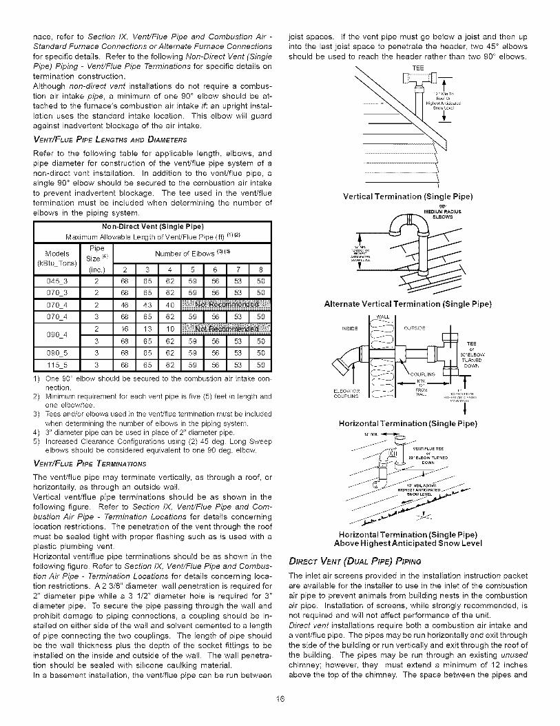
VENT/FLuEPIPELENGTHS AND DIAMETERS
Refer to the following table for applicable length, elbows, andpipe diameter for construction of the vent/flue pipe system of a
non-direct vent installation, in addition to the vent/flue pipe, a
single 90 ° elbow should be secured to the combustion air intake
to prevent inadvertent blockage. The tee used in the vent/flue
termination must be included when determining the number of
elbows in the piping system.
Non-Direct Vent (Single Pipe)
Maximum Allowable Length of Vent/Flue Pipe (ft) (1)(2)
PipeModels Size (4) Number of Elbows (3)(9
(kBtu_Tons)(inc.) 2 3 4 5 6 7 8
045_3 2 68 65 62 59 56 53 50
070_3 2 68 65 62 59 56 53 50
070_4 2 46 43 40
59 _ 56 53 50070_4 3 68 65 62
090_43 68 65 62 59 56 53 50
090_5 3 68 65 62 59 56 53 50
115_5 3 68 65 62 59 56 53 50
1 One 90 ° elbow should be secured to the combustion air intake con-nection.
2 Minimum requirement for each vent pipe is five (5) feet in length andone elbow/tee.
3 Tees and/or elbows used in the vent/flue termination must be included
when determining the number of elbows in the piping system.4 3" diameter pipe can be used in place of 2" diameter pipe.5 Increased Clearance Configurations using (2) 45 deg. Long Sweep
elbows should be considered equivalent to one 90 deg. elbow.
VENT/FLuEPIPE TERMINATIONS
The vent/flue pipe may terminate vertically, as through a roof, orhorizontally, as through an outside wall.
Vertical vent/flue pipe terminations should be as shown in the
following figure. Refer to Section IX, Vent/Flue Pipe and Com-
bustion Air Pipe - Termination Locations for details concerning
location restrictions. The penetration of the vent through the roof
must be sealed tight with proper flashing such as is used with aplastic plumbing vent.
Horizontal vent/flue pipe terminations should be as shown in the
following figure. Refer to Section IX, Vent/Flue Pipe and Combus-
tion Air Pipe - Termination Locations for details concerning loca-tion restrictions. A 2 3/8" diameter wall penetration is required for
2" diameter pipe while a 3 1/2" diameter hole is required for 3"
diameter pipe. To secure the pipe passing through the wall and
prohibit damage to piping connections, a coupling should be in-
stalled on either side of the wall and solvent cemented to a length
of pipe connecting the two couplings. The length of pipe shouldbe the wall thickness plus the depth of the socket fittings to be
installed on the inside and outside of the wall. The wall penetra-
tion should be sealed with silicone caulking material.
In a basement installation, the vent/flue pipe can be run between
joist spaces. If the vent pipe must go below a joist and then up
into the last joist space to penetrate the header, two 45 ° elbowsshould be used to reach the header rather than two 90 ° elbows.
TEE
f12" Min To
Roof OF
Highest AnticipatedSnow Level
Vertical Termination (Single Pipe)90 o
MEDIUM RADIUSELBOWS
Alternate Vertical Termination (Single Pipe)
INSIDE
EL BOW O R
COUPLING
WALL
OUTSIDE
_ _ TEE
90OE°LBOW
TURNED
DOWN
_ MIN TFROM IWALL TOGROUtDOR
H_H E ST ANTICIPATED
s_ow LESL
tHorizontal Termination (Single Pipe)
iz' MtN _
VENT/FLUE°__,4_,_. .TEE
90" ELBOW TURNEDDOWN
Horizontal Termination (Single Pipe)Above Highest Anticipated Snow Level
DIRECT VENT (DUAL PIPE) PIPING
The inlet air screens provided in the installation instruction packetare available for the installer to use in the inlet of the combustion
air pipe to prevent animals from building nests in the combustion
air pipe. Installation of screens, while strongly recommended, isnot required and will not affect performance of the unit.
Direct vent installations require both a combustion air intake and
a vent/flue pipe. The pipes may be run horizontally and exit through
the side of the building or run vertically and exit through the roof of
the building. The pipes may be run through an existing unused
chimney; however, they must extend a minimum of 12 inchesabove the top of the chimney. The space between the pipes and
16
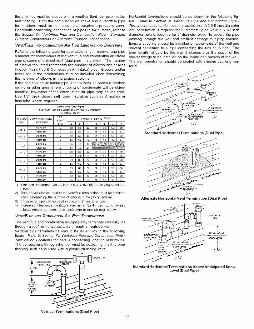
the chimney must be closed with a weather tight, corrosion resis-
tant flashing. Both the combustion air intake and a vent/flue pipe
terminations must be in the same atmospheric pressure zone.
For details concerning connection of pipes to the furnace, refer to
the Section IX, Vent/Flue Pipe and Combustion Pipe - StandardFurnace Connections or Alternate Furnace Connections.
VENT/FLuE AND COMBUSTION AIR PIPE LENGTHS AND DIAMETERS
Refer to the following table for applicable length, elbows, and pipediameter for construction of the vent/flue and combustion air intake
pipe systems of a direct vent (dual pipe) installation. The number
of elbows tabulated represents the number of elbows and/or tees
in each (Vent/Flue & Combustion Air Intake) pipe. Elbows and/ortees used in the terminations must be included when determining
the number of elbows in the piping systems.
If the combustion air intake pipe is to be installed above a finished
ceiling or other area where dripping of condensate will be objec-
tionable, insulation of the combustion air pipe may be required.Use 1/2" thick closed cell foam insulation such as Armaflex or
Insultube where required.
Direct Vent (Dual Pipe)
Maximum Allowable Length of VentJFlue & Combustion
Air Intake Pipe (ft)
I Vent/Flue/Air Intake PipeUnit(Btu)input Termin_ion Size(in.) (4)
Standard 2 68 65 62 59 56 53 50O45_3
/_temate 2 55 52 49 46 43 40 37
Standard 2 68 65 62 59 56 53 50070_3
/_temate 2 55 52 49 46 43 40 37
070_4 Standard 2 46 43 40 ................................._:_ 9_er_!i/_temate 2 33 30 27
Standard 3 68 65 62 59 56 53 50070_4
/_temate 3 54 51 48 45 42 39 36
Standard 3 68 65 62 59 56 53 50O9O_4
/_ternate 3 55 52 49 46 43 40 37
Standard 3 68 65 62 59 56 53 50O9O_5
/_temate 3 55 52 49 46 43 40 37
Standard 3 68 65 62 59 56 53 50115_5
/_temate 3 55 52 49 46 43 40 37
1 ) Minimum requirement for each vent pipe is five (5) feet in length and oneelbow/tee.
2) Tees and/or elbows used in the vent/flue termination must be includedwhen determining the number of elbows in the piping system.
3) 3" diameter pipe can be used in place of 2" diameter pipe.4) Increased Clearance Configurations using (2) 45 deg. Long Sweep
elbows should be considered equivalent to one 90 deg. elbow.
VENT/FLuE AND COMBUSTION AIR PIPE TERMINATIONS
The vent/flue and combustion air pipes may terminate vertically, as
through a roof, or horizontally, as through an outside wall.
Vertical pipe terminations should be as shown in the followingfigure. Refer to Section IX, Vent/Flue Pipe and Combustion Pipe -
Termination Locations for details concerning location restrictions.
The penetrations through the roof must be sealed tight with proper
flashing such as is used with a plastic plumbing vent.TEE
COMBUSTION ME_U_P._IUSVENT/FLUE
1
....Vertical Terminations (Dual Pipe)
Horizontal terminations should be as shown in the following fig-
ure. Refer to Section IX, Vent/Flue Pipe and Combustion Pipe -Termination Location for location restrictions. A 2 3/8 inch diameter
wall penetration is required for 2" diameter pipe while a 3 1/2 inch
diameter hole is required for 3" diameter pipe. To secure the pipepassing through the wall and prohibit damage to piping connec-
tions, a coupling should be installed on either side of the wall and
solvent cemented to a pipe connecting the two couplings. The
pipe length should be the wall thickness plus the depth of thesocket fittings to be installed on the inside and outside of the wall.
The wall penetration should be sealed with silicone caulking ma-terial.
gooMEDIUM RADIUS
SNOW LEVEL
SNOW LEVEL
Standard Horizontal Terminations (Dual Pipe)
_2"MI_. ABOVE_I_H_ST A_TIClPAT_D
SNOWLEVE_
Alternate Horizontal Vent Termination (Dual Pipe)
_24" MAX.
AIR_ __,,_,,,_'JINTAKE, H IG H sNoAwLIEIvEL EEDE STNTcBpOAVT,
/ MEDIUM _ SNOW LEVEL _11 _
Standard Horizontal Terminations Above Anticipated SnowLevel (Dual Pipe)
17
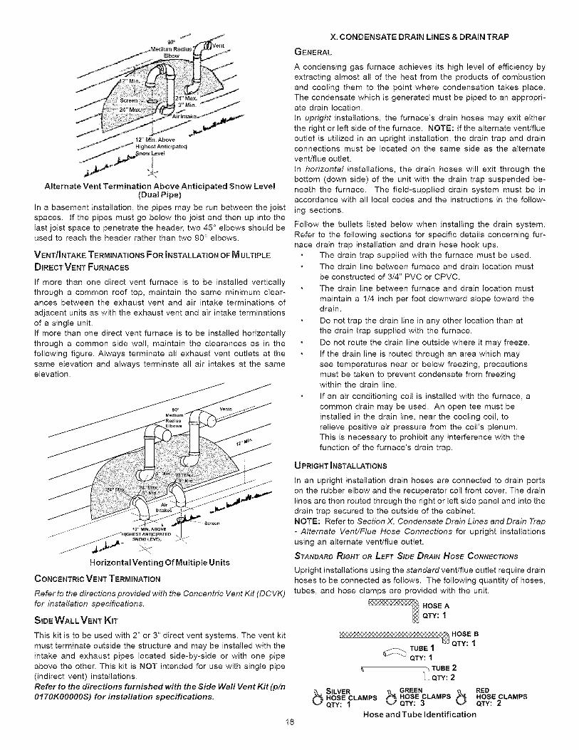
J90°
X. CONDENSATE DRAIN LINES & DRAIN TRAP
GENERAL
12" Min. Above
_ Highest Anticipate_
Alternate Vent Termination Above Anticipated Snow Level(Dual Pipe)
In a basement installation, the pipes may be run between the joist
spaces, if the pipes must go below the joist and then up into the
last joist space to penetrate the header, two 45 ° elbows should beused to reach the header rather than two 90 ° elbows.
VENT/INTAKE TERMINATIONS FOR INSTALLATION OF M ULTIPLE
DIRECT VENT FURNACES
If more than one direct vent furnace is to be installed vertically
through a common roof top, maintain the same minimum clear-ances between the exhaust vent and air intake terminations of
adjacent units as with the exhaust vent and air intake terminations
of a single unit.
If more than one direct vent furnace is to be installed horizontally
through a common side wall, maintain the clearances as in the
following figure. Always terminate all exhaust vent outlets at the
same elevation and always terminate all air intakes at the sameelevation.
A condensing gas furnace achieves its high level of efficiency by
extracting almost all of the heat from the products of combustion
and cooling them to the point where condensation takes place.The condensate which is generated must be piped to an appropri-ate drain location.
In upright installations, the furnace's drain hoses may exit either
the right or left side of the furnace. NOTE: If the alternate vent/flueoutlet is utilized in an upright installation, the drain trap and drainconnections must be located on the same side as the alternate
vent/flue outlet.
In horizontal installations, the drain hoses will exit through the
bottom (down side) of the unit with the drain trap suspended be-
neath the furnace. The field-supplied drain system must be inaccordance with all local codes and the instructions in the follow-
ing sections.
Follow the bullets listed below when installing the drain system.
Refer to the following sections for specific details concerning fur-
nace drain trap installation and drain hose hook ups.
The drain trap supplied with the furnace must be used.
The drain line between furnace and drain location must
be constructed of 3/4" PVC or CPVC.
The drain line between furnace and drain location must
maintain a 1/4 inch per foot downward slope toward thedrain.
Do not trap the drain line in any other location than atthe drain trap supplied with the furnace.
Do not route the drain line outside where it may freeze.
If the drain line is routed through an area which may
see temperatures near or below freezing, precautions
must be taken to prevent condensate from freezingwithin the drain line.
If an air conditioning coil is installed with the furnace, acommon drain may be used. An open tee must be
installed in the drain line, near the cooling coil, to
relieve positive air pressure from the coil's plenum.
This is necessary to prohibit any interference with the
function of the furnace's drain trap.
U PRIGHT _NSTALLATIONS
Horizontal Venting Of Multiple Units
CONCENTRIC VENT TERMINATION
Refer to the directions provided with the Concentric Vent Kit (DCVK)
for installation specifications.
SIDE WALL VENT KIT
This kit is to be used with 2" or 3" direct vent systems. The vent kit
must terminate outside the structure and may be installed with the
intake and exhaust pipes located side-by-side or with one pipe
above the other. This kit is NOT intended for use with single pipe(indirect vent) installations.
Refer to the directions furnished with the Side Wall Vent Kit (pin
0170K00000S) for installation specifications.
In an upright installation drain hoses are connected to drain portson the rubber elbow and the recuperator coil front cover. The drain
lines are then routed through the right or left side panel and into the
drain trap secured to the outside of the cabinet.
NOTE: Refer to Section X, Condensate Drain Lines and Drain Trap- Alternate Vent/Flue Hose Connections for upright installations
using an alternate vent/flue outlet.
STANDARD RIGHT OR LEFT SIDE DRAIN Hose CONNECTIONS
Upright installations using the standard vent/flue outlet require drain
hoses to be connected as follows. The following quantity of hoses,
tubes, and hose clamps are provided with the unit.
HOSE AQTY: 1
Nxx'_.,_x,'z'x4Z'_;N_'_:Zxx'_Z,_-x_x,'z'x4Z'_HOSE BQTY: 1_TUBE 1
QTY: 1
"_ TUBE 2U QTY: 2
bs,,vE, bO"EE" b"E0HOSE CLAMPS HOSE CLAMPS HOSE CLAMPSQTY: 1 QTY: 3 QTY: 2
Hose and Tube identification18
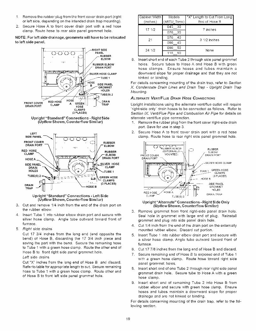
1. Remove the rubber plug from the front cover drain port (right
or left side, depending on the intended drain trap mounting).
2. Secure Hose A to front cover drain port with a red hose
clamp. Route hose to rear side panel grommet hole.
NOTE: For left side drainage, grommets will have to be relocated
to left side panel.
FRONT COVER
DRAIN PORT
,o.o:o. 1 R Bo w"
ERE'BOWS DRAIN PORT
SILVER HOSE CLAMP
TUBE 1
IOBSE SIDE PANEL
CLAMPS
(3 PLACES)
Upright "Standard" Connections =Right Side(Upflow Shown, Counterflow Similar)
3.
4.
5.
LEFT
SIDE PANEL
FRONTCOVERDRAINPORT
RED HOSECLAMP
HOSEA
SIDEPANELDRAINHOLES
TUBE
DRAINHOSE BTRAP
RUBBER
RUBBER
DRAIN PORT
SILVER HOSECLAMP
GREENHOSECLAMPS
(3 PLACES)
Upright "Standard" Connections =Left Side(Upflow Shown, Counterflow Similar)
Cut and remove 1/4 inch from the end of the drain port onthe rubber elbow.
Insert Tube 1 into rubber elbow drain port and secure with
silver hose clamp. Angle tube outward toward front offurnace.
Right side drains
Cut 17 3/4 inches from the long end (end opposite the
bend) of Hose B, discarding the 17 3/4 inch piece and
saving the part with the bend. Secure the remaining hose
to Tube 1 with a green hose clamp. Route the other end ofHose B to front right side panel grommet hole.
Left side drains
Cut "X" inches from the long end of Hose B and discard.
Refer to table for appropriate length to cut. Secure remaining
hose to Tube 1 with a green hose clamp. Route other endof Hose B to front left side panel grommet hole.
Cabinet Width
(inches)
17 1/2
21
24 1/2
Models
(kBTU_Tons)
045 30
070 30
070 40
090 40
090 50
1!5 50
"X"Lengthto Cut From LongEnd of Hose B
7 inches
3 1/2inches
None
6. Insert short end of each Tube 2 through side panel grommet
holes. Secure tubes to Hose A and Hose B with green
hose clamps. Ensure hoses and tubes maintain adownward slope for proper drainage and that they are not
kinked or binding.
For details concerning mounting of the drain trap, refer to SectionX, Condensate Drain Lines and Drain Trap - Upright Drain Trap
Mounting.
ALTERNATE VENT/FLuE DRAIN HOSE CONNECTIONS
Upright installations using the alternate vent/flue outlet will require
"right-side only" drain hoses to be connected as follows. Refer to
Section IX, Vent/Flue Pipe and Combustion Air Pipe for details onalternate vent/flue pipe connection.
1. Remove the rubber plug from the front cover right-side drain
port. Save for use in step 3.
2. Secure Hose A to front cover drain port with a red hose
clamp. Route hose to rear right side panel grommet hole.
(_ (RUBBER ELBOW RUBBER
(EXTERNALLY-- ELBOWFRONT COVER MOUNTED) _DRAIN PORT
ORAINPORT/
....... _ SILVER HOSE CLAMP
--TUBE 1 GREEN HOSE
CLAMPS(3 PLACES)
HOSE B
r_ I _ SIDE PANEL
GROMMETHOLES
RED HOSEJ HOSE A DRAIN TRAP
CLAMP TUBE(S) 2
Upright "Alternate" Connections - Right Side Only(Upflow Shown, Counterflow Similar)
3. Remove grommet from front right-side panel drain hole.
Seal hole in grommet with large end of plug. Reinstallgrommet and plug into side panel drain hole.
4. Cut 1/4 inch from the end of the drain port on the externallymounted rubber elbow. Discard cut portion.
5. Insert Tube 1 into rubber elbow drain port and secure with
a silver hose clamp. Angle tube outward toward front offurnace.
6. Cut 17 7/8 inches from the long end of Hose B and discard.
7. Secure remaining end of Hose B to exposed end of Tube 1
with a green hose clamp. Route hose toward right side
panel grommet holes.
8. Insert short end of one Tube 2 through rear right side panel
grommet drain hole. Secure tube to Hose A with a greenhose clamp.
9. Insert short end of remaining Tube 2 into Hose B fromrubber elbow and secure with green hose clamp. Ensure
hoses and tubes maintain a downward slope for proper
drainage and are not kinked or binding.
For details concerning mounting of the drain trap, refer to the fol-
lowing section.
19
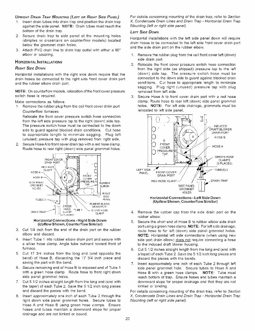
UPRIGHT DRAIN TRAP MOUNTING (LEFT OR RIGHT SIDE PANEL)
1. Insert drain tubes into drain trap and position the drain trapagainst the side panel. NOTE: Drain tubes must reach the
bottom of the drain trap.
2. Secure drain trap to side panel at the mounting holes
(dimples or crosshairs on counterflow models) located
below the grommet drain holes.
3. Attach PVC drain line to drain trap outlet with either a 90 °
elbow or coupling.
HORIZONTAL INSTALLATIONS
RIGHT SIDE DOWN
Horizontal installations with the right side down require that the
drain hoses be connected to the right side front cover drain port
and the rubber elbow drain port.
NOTE: On counterflow models, relocation of the front cover pressure
switch hose is required.
Make connections as follows:
1. Remove the rubber plug from the coil front cover drain port.
Counterflow furnaces
Relocate the front cover pressure switch hose connection
from the left side pressure tap to the right (down) side tap.
The pressure switch hose must be connected to the down
side to guard against blocked drain conditions. Cut hoseto appropriate length to minimize sagging. Plug left
(unused) pressure tap with plug removed from right side.
2. Secure Hose A to front cover drain tap with a red hose clamp.
Route hose to rear right (down) side panel grommet holes.
3.
4.
5.
6.
7.
8.
FRONT COVERDRAIN PORT
IRED HOSE
CLAMPHOSE A
HOSE _
SIDE PANEL \ _BBERGROMMET
HOLES _ ELBOW
RIGHT
_ S{DEPANEL
RUBBER ELBOW
GREEN UXBE1 _ DRA_N PORTHOSE T SILVER HOSECLAMP
CLAMP(3 PLACES)
Horizontal Connections - Right Side Down(Upflow Shown, Counterflow Similar)
Cut 1/4 inch from the end of the drain port on the rubberelbow and discard.
Insert Tube 1 into rubber elbow drain port and secure with
a silver hose clamp. Angle tube outward toward front offurnace.
Cut 17 3/4 inches from the long end (end opposite the
bend) of Hose B, discarding the 17 3/4 inch piece andsaving the part with the bend.
Secure remaining end of Hose B to exposed end of Tube 1with a green hose clamp. Route hose to front right down
side panel grommet holes.
Cut 5 1/2 inches straight length from the long end (end with
the taper) of each Tube 2. Save the 5 1/2 inch long pieces
and discard the pieces with the bend.
Insert approximately one inch of each Tube 2 through the
right down side panel grommet holes. Secure tubes to
Hose A and Hose B using green hose clamps. Ensure
hoses and tubes maintain a downward slope for properdrainage and are not kinked or bound.
For details concerning mounting of the drain trap, refer to Section
X, Condensate Drain Lines and Drain Trap - Horizontal Drain Trap
Mounting (left or right side panel).
LEFT SIDE DOWN
Horizontal installations with the left side panel down will require
drain hoses to be connected to the left side front cover drain port
and the side drain port on the rubber elbow.
1.
2.
3.
Remove the rubber plug from the coil front cover left (down)side drain port.
Relocate the front cover pressure switch hose connectionfrom the right side (as shipped) pressure tap to the left
(down) side tap. The pressure switch hose must be
connected to the down side to guard against blocked drain
conditions. Cut hose to appropriate length to minimize
sagging. Plug right (unused) pressure tap with plugremoved from left side.
Secure Hose A to front cover drain port with a red hose
clamp. Route hose to rear left (down) side panel grommetholes. NOTE: For left side drainage, grommets must be
relocated to left side panel.
/| " _ _l,_._ -- GREEN HOSE/ t.P_h% / CLAMPS
"/_ _' _==_//.. _ (3 PLACES)LEFT SIDE _ / / _TUBE(S) 2
PANEL FRONT COVERJ / //
DRAIN PORT / y_
RED HOSE CLAMP SIGIDEI_A2E_ETL _,_ DRAIN TRAP
HOLES
Horizontal Connections - Left Side Down(Upflow Shown, Counterflow Similar)
4. Remove the rubber cap from the side drain port on therubber elbow.
5. Secure the short end of Hose B to rubber elbow side drain
port using a green hose clamp. NOTE: For left side drainage,route hose to far left (down) side panel grommet holes.
NOTE: Horizontal left side connections (when using new
side port drain elbow) does not require connecting a hose
to the induced draft blower housing.
6. Cut 5 1/2 inches straight length from the long end (end with
a taper) of each Tube 2. Save the 5 1/2 inch long pieces and
discard the pieces with the bends.
7. Insert approximately one inch of each Tube 2 through left
side panel grommet hole. Secure tubes to HoseAand
Hose B with a green hose clamps. NOTE: Tube mustreach bottom of trap. Ensure hoses and tubes maintain a
downward slope for proper drainage and that they are not
kinked or binding.
For details concerning mounting of the drain trap, refer to Section
X, Condensate Drain Lines and Drain Trap - Horizontal Drain Trap
Mounting (left or right side panel).
20
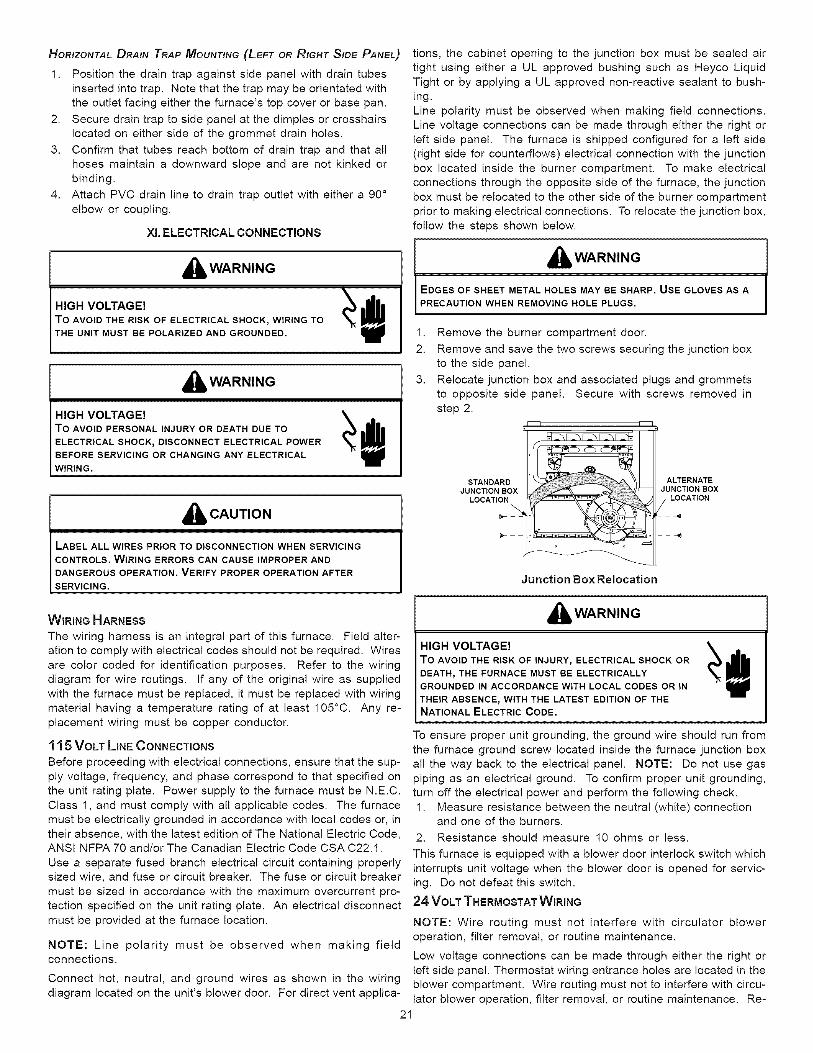
HORIZONTAL DRAIN TRAP MOUNTING (LEFT OR RIGHT SIDE PANEL)
1. Position the drain trap against side panel with drain tubes
inserted into trap. Note that the trap may be orientated with
the outlet facing either the furnace's top cover or base pan.
2. Secure drain trap to side panel at the dimples or crosshairs
located on either side of the grommet drain holes.
3. Confirm that tubes reach bottom of drain trap and that all
hoses maintain a downward slope and are not kinked or
binding.
4. Attach PVC drain line to drain trap outlet with either a 90 °
elbow or coupling.
Xl. ELECTRICAL CONNECTIONS
,_ WARNING
HIGH VOLTAGE!
To AVOID THE RISK OF ELECTRICAL SHOCK_ WIRING TOTHE UNIT MUST BE POLARIZED AND GROUNDED.
,_ WARNING
HIGH VOLTAGE! _ W_
To AVOID PERSONAL INJURY OR DEATH DUE TO
ELECTRICAL SHOCK_ DISCONNECT ELECTRICAL POWERBEFORE SERVICING OR CHANGING ANY ELECTRICALWIRING.
,_ CAUTION
LABEL ALL WIRES PRIOR TO DISCONNECTION WHEN SERVICINGCONTROLS. WIRING ERRORS CAN CAUSE IMPROPER ANDDANGEROUS OPERATION. VERIFY PROPER OPERATION AFTER
SERVICING.
tions, the cabinet opening to the junction box must be sealed air
tight using either a UL approved bushing such as Heyco Liquid
Tight or by applying a UL approved non-reactive sealant to bush-
ing.
Line polarity must be observed when making field connections.Line voltage connections can be made through either the right or
left side panel. The furnace is shipped configured for a left side
(right side for counterflews) electrical connection with the junction
box located inside the burner compartment. To make electricalconnections through the opposite side of the furnace, the junction
box must be relocated to the other side of the burner compartment
prior to making electrical connections. To relocate the junction box,
follow the steps shown below.
,_ WARNING
EDGES OF SHEET METAL HOLES MAY BE SHARP. USE GLOVES AS APRECAUTION WHEN REMOVING HOLE PLUGS.
1.
2
3.
Remove the burner compartment door.
Remove and save the two screws securing the junction boxto the side panel.
Relocate junction box and associated plugs and grommetsto opposite side panel. Secure with screws removed in
step 2.
STANDARD _ ALTERNATE
JUNCTION BOX JUNCTION BOXLOCATION , LOCATION
\
Junction Box Relocation
WIRING HARNESS
The wiring harness is an integral part of this furnace. Field alter-ation to comply with electrical codes should not be required. Wires
are color coded for identification purposes. Refer to the wiring
diagram for wire routings. If any of the original wire as supplied
with the furnace must be replaced, it must be replaced with wiring
material having a temperature rating of at least 105°C. Any re-
placement wiring must be copper conductor.
1 1 5 VOLT LINE CONNECTIONS
Before proceeding with electrical connections, ensure that the sup-
ply voltage, frequency, and phase correspond to that specified on
the unit rating plate. Power supply to the furnace must be N.E.C.
Class 1, and must comply with all applicable codes. The furnacemust be electrically grounded in accordance with local codes or, in
their absence, with the latest edition of The National Electric Code,ANSI NFPA 70 and/or The Canadian Electric Code CSA C22.1.
Use a separate fused branch electrical circuit containing properlysized wire, and fuse or circuit breaker. The fuse or circuit breaker
must be sized in accordance with the maximum overcurrent pro-tection specified on the unit rating plate. An electrical disconnect
must be provided at the furnace location.
NOTE: Line polarity must be observed when making fieldconnections.
Connect hot, neutral, and ground wires as shown in the wiring
diagram located on the unit's blower door. For direct vent applica-
,_ WARNING
HIGH VOLTAGE! _ W_
To AVOID THE RISK OF INJURY, ELECTRICAL SHOCK ORDEATH_ THE FURNACE MUST BE ELECTRICALLYGROUNDED IN ACCORDANCE WITH LOCAL CODES OR IN
THEIR ABSENCE_ WITH THE LATEST EDITION OF THENATIONAL ELECTRIC CODE.
To ensure proper unit grounding, the ground wire should run from
the furnace ground screw located inside the furnace junction box
all the way back to the electrical panel. NOTE: Do not use gas
piping as an electrical ground. To confirm proper unit grounding,turn off the electrical power and perform the following check.
1. Measure resistance between the neutral (white) connectionand one of the burners.
2. Resistance should measure 10 ohms or less.
This furnace is equipped with a blower door interlock switch which
interrupts unit voltage when the blower door is opened for servic-
ing. Do not defeat this switch.
24 VOLT THERMOSTAT WIRING
NOTE: Wire routing must not interfere with circulator blower
operation, filter removal, or routine maintenance.
Low voltage connections can be made through either the right or
left side panel. Thermostat wiring entrance holes are located in the
blower compartment. Wire routing must not to interfere with circu-lator blower operation, filter removal, or routine maintenance. Re-
21
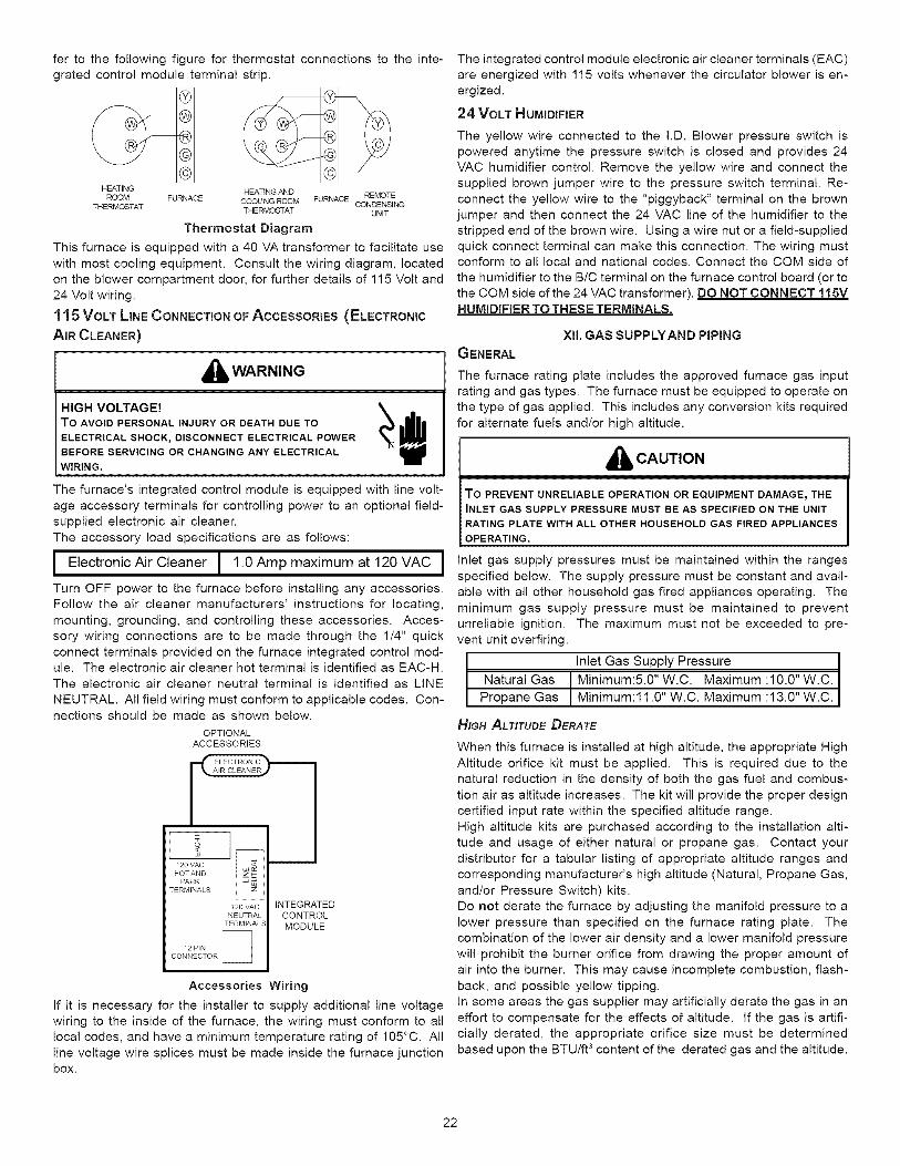
fer to the following figure for thermostat connections to the inte-
grated control module terminal strip.
HEATING
ROOM FURNACE REMOTE
THERMOSTAT CONDENSINGUNIT
HEATING AND
CCOU NG ROOM FURNACE
THERMOSTAT
Thermostat Diagram
This furnace is equipped with a 40 VA transformer to facilitate use
with most cooling equipment. Consult the wiring diagram, located
on the blower compartment door, for further details of 115 Volt and
24 Volt wiring.
11 5 VOLT LINE CONNECTION OF ACCESSORIES(ELECTRONIC
AIR CLEANER)
,_ WARNING
HIGH VOLTAGE! _ _I_
To AVOID PERSONAL INJURY OR DEATH DUE TO
ELECTRICAL SHOCK_ DISCONNECT ELECTRICAL POWERBEFORE SERVICING OR CHANGING ANY ELECTRICALWIRING,
The furnace's integrated control module is equipped with line volt-
age accessory terminals for controlling power to an optional field-supplied electronic air cleaner.
The accessory load specifications are as follows:
I Electronic Air Cleaner I 1.0 Amp maximum at 120 VAC I
Turn OFF power to the furnace before installing any accessories.Follow the air cleaner manufacturers' instructions for locating,
mounting, grounding, and controlling these accessories. Acces-
sory wiring connections are to be made through the 1/4" quick
connect terminals provided on the furnace integrated control mod-ule. The electronic air cleaner hot terminal is identified as EAC-H.The electronic air cleaner neutral terminal is identified as LINE
NEUTRAL. All field wiring must conform to applicable codes. Con-nections should be made as shown below.
OPTIONALACCESSORIES
120 VAC INTEGRATED
NEUTRAL CONTROL
TERMiNALs< MODULE
Accessories Wiring
If it is necessary for the installer to supply additional line voltage
wiring to the inside of the furnace, the wiring must conform to alllocal codes, and have a minimum temperature rating of 105°C. All
line voltage wire splices must be made inside the furnace junctionbox.
The integrated control module electronic air cleaner terminals (EAC)
are energized with 115 volts whenever the circulator blower is en-
ergized.
24 VOLT H UMIDIFEER
The yellow wire connected to the I.D. Blower pressure switch ispowered anytime the pressure switch is closed and provides 24
VAC humidifier control. Remove the yellow wire and connect the
supplied brown jumper wire to the pressure switch terminal. Re-connect the yellow wire to the "piggyback" terminal on the brown
jumper and then connect the 24 VAC line of the humidifier to the
stripped end of the brown wire. Using a wire nut or a field-suppliedquick connect terminal can make this connection. The wiring mustconform to all local and national codes. Connect the COM side of
the humidifier to the B/C terminal on the furnace control board (or tothe COM side of the 24 VAC transformer). DO NOT CONNECT 115VHUMIDIFIER TO THESE TERMINALS.
XII. GAS SUPPLYAND PIPING
GENERAL
The furnace rating plate includes the approved furnace gas input
rating and gas types. The furnace must be equipped to operate on
the type of gas applied. This includes any conversion kits required
for alternate fuels and/or high altitude.
,_ CAUTION
To PREVENT UNRELIABLE OPERATION OR EQUIPMENT DAMAGE_ THEiNLET GAS SUPPLY PRESSURE MUST BE AS SPECIFIED ON THE UNITRATING PLATE WITH ALL OTHER HOUSEHOLD GAS FIRED APPLIANCESOPERATING.
Inlet gas supply pressures must be maintained within the rangesspecified below. The supply pressure must be constant and avail-
able with all other household gas fired appliances operating. The
minimum gas supply pressure must be maintained to prevent
unreliable ignition. The maximum must not be exceeded to pre-
vent unit overfiring.
Inlet Gas Supply Pressure
Natural Gas / Minimum:5.0" W.C. Maximum :10.0" W.C.
PropaneGas [ Minimum:11.0"W.C. Maximum :13.0"W.C.
HIGH ALTITUDE DERATE
When this furnace is installed at high altitude, the appropriate HighAltitude orifice kit must be applied. This is required due to the
natural reduction in the density of both the gas fuel and combus-
tion air as altitude increases. The kit will provide the proper design
certified input rate within the specified altitude range.
High altitude kits are purchased according to the installation alti-tude and usage of either natural or propane gas. Contact your
distributor for a tabular listing of appropriate altitude ranges and
corresponding manufacturer's high altitude (Natural, Propane Gas,
and/or Pressure Switch) kits.
Do not derate the furnace by adjusting the manifold pressure to alower pressure than specified on the furnace rating plate. The
combination of the lower air density and a lower manifold pressure
will prohibit the burner orifice from drawing the proper amount of
air into the burner. This may cause incomplete combustion, flash-
back, and possible yellow tipping.In some areas the gas supplier may artificially derate the gas in an
effort to compensate for the effects of altitude. If the gas is artifi-
cially derated, the appropriate orifice size must be determined
based upon the BTU/ft 3 content of the derated gas and the altitude.
22
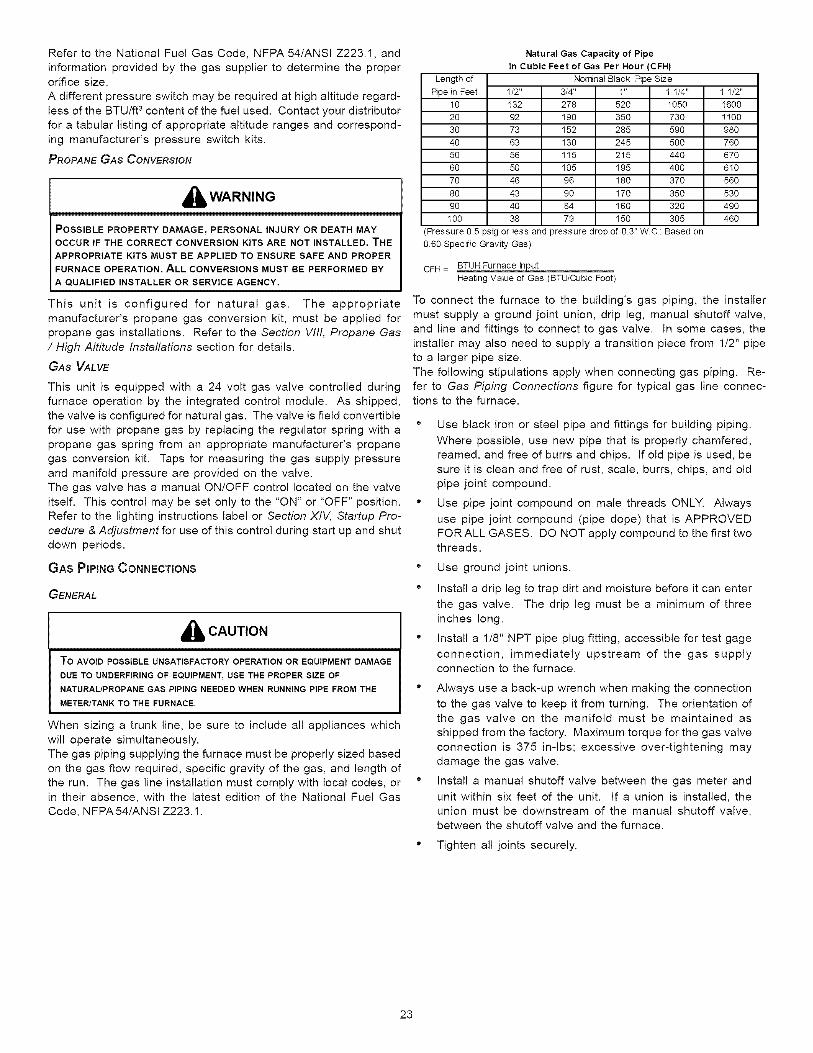
Refer to the National Fuel Gas Code, NFPA 54/ANSI Z223.1, and
information provided by the gas supplier to determine the properorifice size.
A different pressure switch may be required at high altitude regard-
less of the BTU/ft 3 content of the fuel used. Contact your distributorfor a tabular listing of appropriate altitude ranges and correspond-
ing manufacturer's pressure switch kits.
PROPANE GAS CONVERSION
_WARNING
POSSIBLE PROPERTY DAMAGE, PERSONAL INJURY OR DEATH MAYOCCUR IF THE CORRECT CONVERSION KITS ARE NOT INSTALLED. THE
APPROPRIATE KITS MUST BE APPLIED TO ENSURE SAFE AND PROPER
FURNACE OPERATION. ALL CONVERSIONS MUST BE PERFORMED BY
A QUALIFIED INSTALLER OR SERVICE AGENCY.
This unit is configured for natural gas. The appropriate
manufacturer's propane gas conversion kit, must be applied forpropane gas installations. Refer to the Section WII, Propane Gas
/ High Altitude Installations section for details.
GAS VALVE
This unit is equipped with a 24 volt gas valve controlled during
furnace operation by the integrated control module. As shipped,
the valve is configured for natural gas. The valve is field convertible
for use with propane gas by replacing the regulator spring with apropane gas spring from an appropriate manufacturer's propane
gas conversion kit. Taps for measuring the gas supply pressure
and manifold pressure are provided on the valve.
The gas valve has a manual ON/OFF control located on the valve
itself. This control may be set only to the "ON" or "OFF" position.Refer to the lighting instructions label or Section XIV, Startup Pro-
cedure & Adjustment for use of this control during start up and shut
down periods.
GAS PIPING CONNECTIONS
GENERAL
_lb CAUTION
To AVOID POSSIBLE UNSATISFACTORY OPERATION OR EQUIPMENT DAMAGE
DUE TO UNDERFIRING OF EQUIPMENT, USE THE PROPER SIZE OF
NATURAL/PROPANE GAS PIPING NEEDED WHEN RUNNING PiPE FROM THE
METER/TANK TO THE FURNACE.
When sizing a trunk line, be sure to include all appliances which
will operate simultaneously.The gas piping supplying the furnace must be properly sized based
on the gas flow required, specific gravity of the gas, and length of
the run. The gas line installation must comply with local codes, orin their absence, with the latest edition of the National Fuel Gas
Code, NFPA 54/ANSI Z223.1.
Natural Gas Capacity of Pipe
In Cubic Feet of Gas Per Hour (CFH)
Length of Nominal Black Rpe Size
Rpe in Feet 1/2" _4" 1" 1 1/4" 1 1/2"
10 132 278 520 1050 1600
20 92 190 350 730 1100
30 73 152 285 590 980
40 63 130 245 500 760
50 56 115 215 440 670
60 50 105 195 400 610
70 46 96 180 370 560
80 43 90 170 350 530
90 40 84 160 320 490
100 38 79 150 305 460
Pressure 0.5 psig or Iess and pressure drop of 0.3" WC; Based on
060 Specific Gravity Gas)
CFH = BTUH Furnace Inj_t.Heating VaIue of Gas (BTU/Cubic Foot)
To connect the furnace to the building's gas piping, the installer
must supply a ground joint union, drip leg, manual shutoff valve,and line and fittings to connect to gas valve. In some cases, the
installer may also need to supply a transition piece from 1/2" pipe
to a larger pipe size.
The following stipulations apply when connecting gas piping. Re-
fer to Gas Piping Connections figure for typical gas line connec-tions to the furnace.
° Use black iron or steel pipe and fittings for building piping.
Where possible, use new pipe that is properly chamfered,reamed, and free of burrs and chips. If old pipe is used, be
sure it is clean and free of rust, scale, burrs, chips, and old
pipe joint compound.
" Use pipe joint compound on male threads ONLY. Always
use pipe joint compound (pipe dope) that is APPROVEDFOR ALL GASES. DO NOT apply compound to the first twothreads.
° Use ground joint unions.
" Install a drip leg to trap dirt and moisture before it can enter
the gas valve. The drip leg must be a minimum of threeinches long.
" Install a 1/8" NPT pipe plug fitting, accessible for test gage
connection, immediately upstream of the gas supplyconnection to the furnace.
" Always use a back-up wrench when making the connection
to the gas valve to keep it from turning. The orientation of
the gas valve on the manifold must be maintained as
shipped from the factory. Maximum torque for the gas valve
connection is 375 in-lbs; excessive over-tightening may
damage the gas valve.
" Install a manual shutoff valve between the gas meter and
unit within six feet of the unit. If a union is installed, the
union must be downstream of the manual shutoff valve,between the shutoff valve and the furnace.
• Tighten alljoints securely.
23
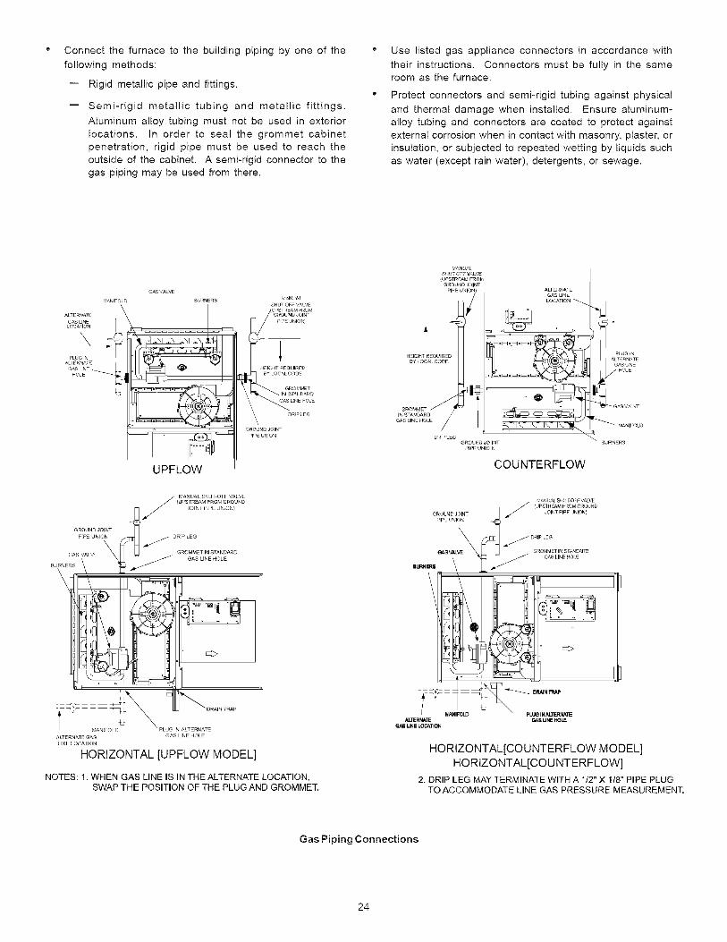
Connect the furnace to the building piping by one of the
following methods:
-- Rigid metallic pipe and fittings.
Semi-rigid metallic tubing and metallic fittings.
Aluminum alloy tubing must not be used in exterior
locations. In order to seal the grommet cabinet
penetration, rigid pipe must be used to reach the
outside of the cabinet. A semi-rigid connector to thegas piping may be used from there.
Use listed gas appliance connectors in accordance with
their instructions. Connectors must be fully in the sameroom as the furnace.
Protect connectors and semi-rigid tubing against physical
and thermal damage when installed. Ensure aluminum-
alloy tubing and connectors are coated to protect against
external corrosion when in contact with masonry, plaster, or
insulation, or subjected to repeated wetting by liquids suchas water (except rain water), detergents, or sewage.
U PF LOW
PIPEUNION1
MANUAL
SHUT OFF VALVEUPSTREAJ_ FR01_I
GROUND JOINT
PIPE UNION) ALTERNATB
GAS LIN_
COUNTERFLOW
]
z E:>
GAS LINE HOLE
LINE LOCATION
HORIZONTAL [UPFLOW MODEL]
NOTES: 1. WHEN GAS LINE IS IN THE ALTERNATE LOCATION,SWAP THE POSITION OF THE PLUG AND GROMMET.
ALnERNA_ GA_ UNE V_LE
G_ UNE LOCATK_
HORIZONTAL[COUNTERFLOW MODEL]HORIZONTAL[COU NTERFLOW]
2. DRIP LEG MAY TERMINATE WITH A 1t2" X 1/8" PIPE PLUGTOACCOMMODATE LINE GAS PRESSURE MEASUREMENT.
Gas Piping Connections
24
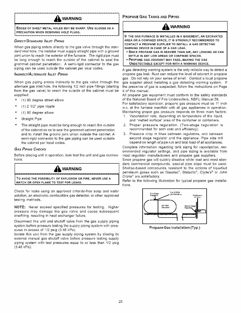
_lb WARNING
EDGES OF SHEET METAL HOLES MAY BE SHARP. USE GLOVES AS A
PRECAUTION WHEN REMOVING HOLE PLUGS.
DIRECT/STANDARD INLET PIPING
When gas piping enters directly to the gas valve through the stan-
dard inlet hole, the installer must supply straight pipe with a ground
joint union to reach the exterior of the furnace. The rigid pipe must
be long enough to reach the outside of the cabinet to seal the
grommet cabinet penetration. A semi-rigid connector to the gaspiping can be used outside the cabinet per local codes.
INDIRECT/ALTERNATE INLET PIPING
When gas piping enters indirectly to the gas valve through the
alternate gas inlet hole, the following 1/2 inch pipe fittings (starting
from the gas valve) to reach the outside of the cabinet must be
supplied:
'_ (1) 90 degree street elbow
" (1) 2 1/2" pipe nipple
" (1) 90 degree elbow
" Straight Pipe
" The straight pipe must be long enough to reach the outside
of the cabinet so as to seal the grommet cabinet penetration
and to install the ground joint union outside the cabinet. A
semi-rigid connector to the gas piping can be used outside
the cabinet per local codes.
GAS PIPING CHECKS
Before placing unit in operation, leak test the unit and gas connec-tions.
,_ WARNING
TO AVOID THE POSSIBILITY OF EXPLOSION OR FIRE, NEVER USE A
MATCH OR OPEN FLAME TO TEST FOR LEAKS.
Check for leaks using an approved chloride-free soap and water
solution, an electronic combustible gas detector, or other approved
testing methods.
NOTE: Never exceed specified pressures for testing. Higher
pressure may damage the gas valve and cause subsequent
overfiring, resulting in heat exchanger failure.
Disconnect this unit and shutoff valve from the gas supply piping
system before pressure testing the supply piping system with pres-
sures in excess of 1/2 psig (3.48 kPa).
Isolate this unit from the gas supply piping system by closing itsexternal manual gas shutoff valve before pressure testing supply
piping system with test pressures equal to or less than 1/2 psig
(3.48 kPa).
PROPANE GAS TANKS AND PIPING
_h, WARNING
IF THE GAS FURNACE IS INSTALLED IN A BASEMENT_ AN EXCAVATED
AREA OR A CONFINED SPACE, IT IS STRONGLY RECOMMENDED TO
CONTACT A PROPANE SUPPLIER TO INSTALL A GAS DETECTING
WARNING DEVICE IN CASE OF A GAS LEAK.
• SINCE PROPANE GAS IS HEAVIER THAN AIR, ANY LEAKING AS CAN
SETTLE IN ANY LOW AREAS OR CONFINED SPACES.
• PROPANE GAS ODORANT MAY FADE r MAKING THE GAS
UNDETECTABLE EXCEPT FOR WITH A WARNING DEVICE.
A gas detecting warning system is the only reliable way to detect a
propane gas leak. Rust can reduce the level of odorant in propane
gas. Do not rely on your sense of smell. Contact a local propanegas supplier about installing a gas detecting warning system. If
the presence of gas is suspected, follow the instructions on Page4 of this manual.
All propane gas equipment must conform to the safety standardsof the National Board of Fire Underwriters, NBFU Manual 58.
For satisfactory operation, propane gas pressure must be 11 inch
w.c. at the furnace manifold with all gas appliances in operation.Maintaining proper gas pressure depends on three main factors:
1. Vaporization rate, depending on temperature of the liquid,and "wetted surface" area of the container or containers.
2. Proper pressure regulation. (Two-stage regulation isrecommended for both cost and efficiency).
3. Pressure drop in lines between regulators, and between
second stage regulator and the appliance. Pipe size willdepend on length of pipe run and total load of all appliances.
Complete information regarding tank sizing for vaporization, rec-
ommended regulator settings, and pipe sizing is available from
most regulator manufacturers and propane gas suppliers.Since propane gas will quickly dissolve white lead and most stan-
dard commercial compounds, special pipe dope must be used.Shellac-based compounds resistant to the actions of liquefied
petroleum gases such as Gasolac ®, Stalactic ®, Clyde's ® or JohnCrane ® are satisfactory.
Refer to the following illustration for typical propane gas installa-tions.
Propane Gas Installation (Typ.)
25
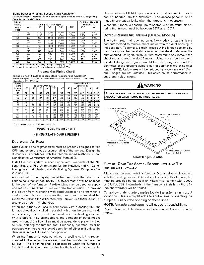
Sizing Between First and Second Stage Regulator*Maximum Propane Capacities listed are based on 2 psig pressure drop at 10 psig settingCapacities in 1,gog BTU/hour.
Nominal Pipe Size
Tubing Size, O.D. Type L Schedule 403t8" 112" 5/8" 3/4" 7/8" 1I2" 3/4"
Pipe or
Tubing
Length,Feet
10 730 1,700 3,200 5,300 8,300 3,200 7,500
20 500 1,!00 2,200 3,700 5,800 2,200 4,200
30 400 920 2,000 2,900 4,700 1,800 4,000
40 370 850 1,700 2,700 4,100 1,600 3,700
50 330 770 1,500 2,400 3,700 1,500 3,400
60 300 700 1,300 2,200 3,300 1,300 3,100
80 260 610 1,200 1,900 2,900 1,200 2,600
100 220 540 1,000 1,700 2,600 1,000 2,300
125 200 490 900 1,400 2,300 900 2,100
150 190 430 830 1,300 2,100 830 1,900
175 170 400 780 1,200 1,900 770 1,700
200 160 380 730 1,100 1,800 720 1,500To convert to capacities at 15 psig settings - mulSpiy by 1 130
To convert to capacities at 5 psig settings - multiply by 0.879
Propane Gas Piping Chart I
Sizing Between Single or Second Stage Regulator and Appliance*Maximum Propane Capacities Listed are Based on t/2" WC pressure drop at 11" WC setting
Pipe or Nominal Pipe SizeTubing Tubing Size, O.D. Type L Schedule 40Length, 3/8" 1_" 518" 3/4" 7/8" 1-1t8" 1/2" 3/4" 1" 1-1_" 1-1/2"
Feet
10 39 92 199 329 501 935 275 567 1,071 2,205 3,30720 28 62 I31 216 346 630 189 393 732 1,496 2,29930 21 50 t07 181 277 500 152 315 590 1,212 1,85840 18 41 90 I45 233 427 129 267 504 1,039 1,55950 18 37 79 131 t98 376 114 237 448 913 1,4t760 16 35 72 I21 187 340 103 217 409 834 1,275
80 13 29 62 104 155 289 89 185 346 724 1,066100 11 26 55 90 I38 255 78 162 307 630 876125 10 24 48 81 122 224 69 146 275 567 866150 9 21 43 72 I09 202 63 132 252 511 787200 8 19 39 66 t00 187 54 112 209 439 665250 8 17 36 60 93 172 48 100 I85 390 590
*Data in accordance with NFPA pamphlet NO 54
Propane Gas Piping Chart II
XIIL CIRCULATING AIR & FILTERS
viewed for visual light inspection or such that a sampling probe
can be inserted into the airstream. The access panel must be
made to prevent air leaks when the furnace is in operation.
When the furnace is heating, the temperature of the return air en-
tering the furnace must be between 55°F and 100°F.
BOTTOM RETURN AIR OPENING [UPFLOW MODELS]
The bottom return air opening on upflow models utilizes a "lance
and cut" method to remove sheet metal from the duct opening in
the base pan. To remove, simply press out the lanced sections by
hand to expose the metal strips retaining the sheet metal over the
duct opening. Using tin snips, cut the metal strips and remove thesheet metal to free the duct flanges. Using the scribe line along
the duct flange as a guide, unfold the duct flanges around the
perimeter of the opening using a pair of seamer pliers or seamer
tongs. NOTE: Airflow area will be reduced by approximately 18% ifduct flanges are not unfolded. This could cause performance is-sues and noise issues.
All, WARNING
EDGES OF SHEET METAL HOLES MAY BE SHARP. USE GLOVES AS A
PRECAUTION WHEN REMOVING HOLE PLUGS.
CUT USING TIN SNIPS
PRESS OUT BY HAND
DUCTWORK - AIR FLOW
Duct systems and register sizes must be properly designed for the
CFM and external static pressure rating of the furnace. Design theductwork in accordance with the recommended methods of "Air
Conditioning Contractors of America" Manual D.
Install the duct system in accordance with Standards of the Na-tional Board of Fire Underwriters for the Installation of Air Condi-
tioning, Warm Air Heating and Ventilating Systems. Pamphlets No.90A and 90B.
A closed return duct system must be used, with the return ductconnected to the furnace. NOTE: Ductwork must never be attached
to the back of the furnace. Flexible joints may be used for supply
and return connections to reduce noise transmission. To preventthe blower from interfering with combustion air or draft when a
central return is used, a connecting duct must be installed be-
tween the unit and the utility room wall. Never us a room, closet, oralcove as a return air chamber.
When the furnace is used in connection with a cooling unit, thefurnace should be installed in parallel with or on the upstream side
of the cooling unit to avoid condensation in the heating element.
With a parallel flow arrangement, the dampers or other means
used to control the flow of air must be adequate to prevent chilled
air from entering the furnace and, if manually operated, must be
equipped with means to prevent operation of either unit unless thedamper is in the full heat or cool position.
When the furnace is installed without a cooling coil, it is recom-
mended that a removable access panel be provided in the outlet
air duct. This opening shall be accessible when the furnace is
installed and shall be of such a size that the heat exchanger can be
CUT FOUR CORNERSAFTER REMOVING SHEETMETAL
;CRIBE LINES OUTLININGDUCT FLANGES
Duct Flange Cut Outs
FILTERS = READ THIS SECTION BEFORE INSTALLING THE
RETURN AIR DUCTWORK
Filters must be used with this furnace, Discuss filter maintenance
with the building owner. Filters do not ship with this furnace, butmust be provided by the installer. Filters must comply with UL900or CAN/ULCS111 standards. If the furnace is installed without fil-
ters, the warranty will be voided.
On upflow units, guide dimples locate the side return cutoutlocations. Use a straight edge to scribe lines connecting thedimples. Cut out the opening on these lines.NOTE: An undersized opening will cause reduced airflow.Refer to Minimum Filter Area tables to determine filter area require-ments.
26
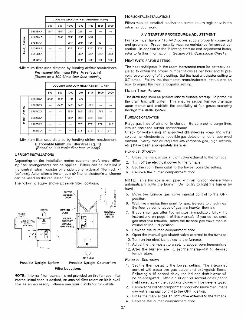
COOLING AIRFLOW REQUIREMENT (CFM)
600I 809I ,0001,2001,,0911800129900453BXA 194" 194" 240 288 .........
O7O3BXA --- 324* 324* 324* 336 ......O
O7O4CXA 291" 291" 336 384
og04CXA 432* 432* 432* 432*
ogO5DXA ......... 388* 388* 388* 480
1155DXA ......... 486* 486* 486* 486*
*Minimum filter area dictated by heating airflow requirement.
Permanent Minimum Filter Area (sq. in)
[Based on a 600 ft/min filter face velocity]
COOLING AIRFLOW REQUIREMENT (CFM)
6oo18oo1lOOO1120o11,o0116oo12ooo0453BXA 388* 388* 480 576 .........
0703BXA --- 647* 647* 847* 672 ......
oO704CXA ...... 583* 583* 672 768 ---
O904CXA ...... 863* 863* 863* 863* ---
O905DXA ......... 777* 777* 777* 960
1155DXA ......... 971" 971" 971" 971"
*Minimum filter area dictated by heating airflow requirement.
Disposable Minimum Filter area (sq. in)[Based on 300 ft/min filter face velocity]
UPRIGHT INSTALLATIONS
Depending on the installation and/or customer preference, differ-
ing filter arrangements can be applied. Filters can be installed in
the central return register or a side panel external filter rack kit
(upflows). As an alternative a media air filter or electronic air cleanercan be used as the requested filter.
The following figure shows possible filter locations.
...................................... i F ;;FILTER --
ACCESS \ .-_ _
DOOR _ iE /
AIRFLOW RETURN-'_ ' / _'}
RETURN RETURN
I/GRILLE GRILLEFILTER /
SUPPORTBRACKET
(PROVIDED)
O
AIR FLOW
Possible Upright Upflow Possible Upright Counterflow
Filter Locations
NOTE: Internal filter retention is not provided on this furnace. If an
internal installation is desired, an internal filter retention kit is avail-
able as an accessory. Please see your distributor for details.
HORIZONTAL INSTALLATIONS
Filters must be installed in either the central return register or in thereturn air duct work.
XlV, STARTUP PROCEDURE &ADJUSTMENT
Furnace must have a 115 VAC power supply properly connected
and grounded. Proper polarity must be maintained for correct op-
eration. In addition to the following start-up and adjustment items,
refer to further information in Section XW, Operational Checks.
HEAT ANTICIPATOR SETTING
The heat anticipator in the room thermostat must be correctly ad-
justed to obtain the proper number of cycles per hour and to pre-
vent "overshooting" of the setting. Set the heat anticipator setting to
0.7 amps. Follow the thermostat manufacturer's instructions onhow to adjust the heat anticipator setting.
DRAIN TRAP PRIMING
The drain trap must be primed prior to furnace startup. To prime, fill
the drain trap with water. This ensures proper furnace drainage
upon startup and prohibits the possibility of flue gases escaping
through the drain system.
FURNACE OPERATION
Purge gas lines of air prior to startup. Be sure not to purge lines
into an enclosed burner compartment.
Check for leaks using an approved chloride-free soap and watersolution, an electronic combustible gas detector, or other approved
method. Verify that all required kits (propane gas, high altitude,
etc.) have been appropriately installed.
FURNACE STARTUP
1. Close the manual gas shutoff valve external to the furnace.
2. Turn off the electrical power to the furnace.
3. Set the room thermostat to the lowest possible setting.
4. Remove the burner compartment door.
NOTE: This furnace is equipped with an ignition device whichautomatically lights the burner. Do not try to light the burner byhand.
5. Move the furnace gas valve manual control to the OFFposition.
6. Wait five minutes then smell for gas. Be sure to check near
the floor as some types of gas are heavier than air.
7. If you smell gas after five minutes, immediately follow theinstructions on page 4 of this manual. If you do not smell
gas after five minutes, move the furnace gas valve manualcontrol to the ON position.
8. Replace the burner compartment door.
9. Open the manual gas shutoff valve external to the furnace.
10. Turn on the electrical power to the furnace.
11. Adjust the thermostat to a setting above room temperature.
12. After the burners are lit, set the thermostat to desired
temperature.
FURNACE SHUTDOWN
1. Set the thermostat to the lowest setting. The integrated
control will close the gas valve and extinguish flame.Following a 15 second delay, the induced draft blower will
be de-energized. After a 100 or 150 second delay period(field selectable), the circulator blower will be de-energized.
2. Remove the burner compartment door and move the furnace
gas valve manual control to the OFF position.
3. Close the manual gas shutoff valve external to the furnace.
4. Replace the burner compartment door.
27
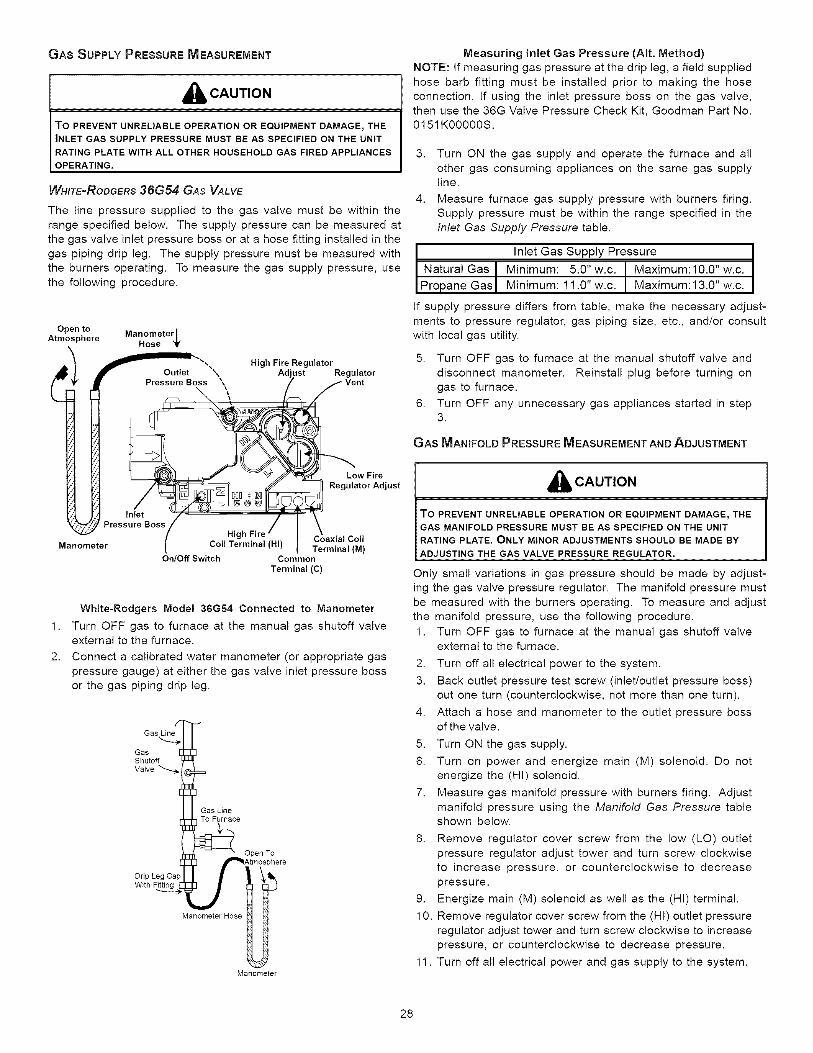
GAS SUPPLY PRESSURE MEASUREMENT
_'li. CAUTION
To PREVENT UNRELIABLE OPERATION OR EQUIPMENT DAMAGE_ THEINLET GAS SUPPLY PRESSURE MUST BE AS SPECIFIED ON THE UNIT
RATING PLATE WITH ALL OTHER HOUSEHOLD GAS FIRED APPLIANCES
OPERATING.
WHITE-RODGERS 36G54 GAS VALVE
The line pressure supplied to the gas valve must be within the
range specified below. The supply pressure can be measured at
the gas valve inlet pressure boss or at a hose fitting installed in the
gas piping drip leg. The supply pressure must be measured with
the burners operating. To measure the gas supply pressure, use
the following procedure.
Open toAtmo_ _here Manometer I
Hose '_t
Pressure Boss 4\
\
High Fire RegulatorJst Regulator
Low Fire
Regulator Adjust
Inlet)ressure Boss
Hig Coaxial Coil
Manometer Coil Terminal (HI) Terminal (M)On/Off Switch Common
Terminal (C)
1.
2.
White-Rodgers Mode! 36G54 Connected to Manometer
Turn OFF gas to furnace at the manual gas shutoff valveexternal to the furnace.
Connect a calibrated water manometer (or appropriate gas
pressure gauge) at either the gas valve inlet pressure boss
or the gas piping drip leg.
GasShutoffValve
UneTo Furnace
Open To
With
Manometer Hose
Manometer
Measuring inlet Gas Pressure (AIt. Method)
NOTE: If measuring gas pressure at the drip leg, a field supplied
hose barb fitting must be installed prior to making the hose
connection. If using the inlet pressure boss on the gas valve,then use the 36G Valve Pressure Check Kit, Goodman Part No.0151K00000S.
3. Turn ON the gas supply and operate the furnace and all
other gas consuming appliances on the same gas supplyline.
4. Measure furnace gas supply pressure with burners firing.
Supply pressure must be within the range specified in theInlet Gas Supply Pressure table.
I Inlet Gas Supply Pressure
t Natural Gas -I- Minimum: 5.0" w.c. t Maximum:10.0" w.c.Propane Gas / Minimum: 1 1.0" w.c. Maximum: 13.0" w.c.
If supply pressure differs from table, make the necessary adjust-
ments to pressure regulator, gas piping size, etc., and/or consultwith local gas utility.
5. Turn OFF gas to furnace at the manual shutoff valve and
disconnect manometer. Reinstall plug before turning ongas to furnace.
6. Turn OFF any unnecessary gas appliances started in step3.
GAS MANIFOLD PRESSURE MEASUREMENT AND ADJUSTMENT
_ CAUTION
TO PREVENT UNRELIABLE OPERATION OR EQUIPMENT DAMAGE_THEGAS MANIFOLD PRESSURE MUST BE AS SPECIFIED ON THE UNITRATING PLATE, ONLY MINOR ADJUSTMENTS SHOULD BE MADE BYADJUSTING THE GAS VALVE PRESSURE REGULATOR.
Only small variations in gas pressure should be made by adjust-ing the gas valve pressure regulator. The manifold pressure must
be measured with the burners operating. To measure and adjust
the manifold pressure, use the following procedure.
1. Turn OFF gas to furnace at the manual gas shutoff valveexternal to the furnace.
2. Turn off all electrical power to the system.
3. Back outlet pressure test screw (inlet/outlet pressure boss)
out one turn (counterclockwise, not more than one turn).
4. Attach a hose and manometer to the outlet pressure bossof the valve.
5. Turn ON the gas supply.
6. Turn on power and energize main (M) solenoid. Do notenergize the (HI) solenoid.
7. Measure gas manifold pressure with burners firing. Adjust
manifold pressure using the Manifold Gas Pressure tableshown below.
8. Remove regulator cover screw from the low (LO) outlet
pressure regulator adjust tower and turn screw clockwiseto increase pressure, or counterclockwise to decrease
pressure.
9. Energize main (M) solenoid as well as the (HI) terminal.
10. Remove regulator cover screw from the (HI) outlet pressure
regulator adjust tower and turn screw clockwise to increase
pressure, or counterclockwise to decrease pressure.
11. Turn off all electrical power and gas supply to the system.
28
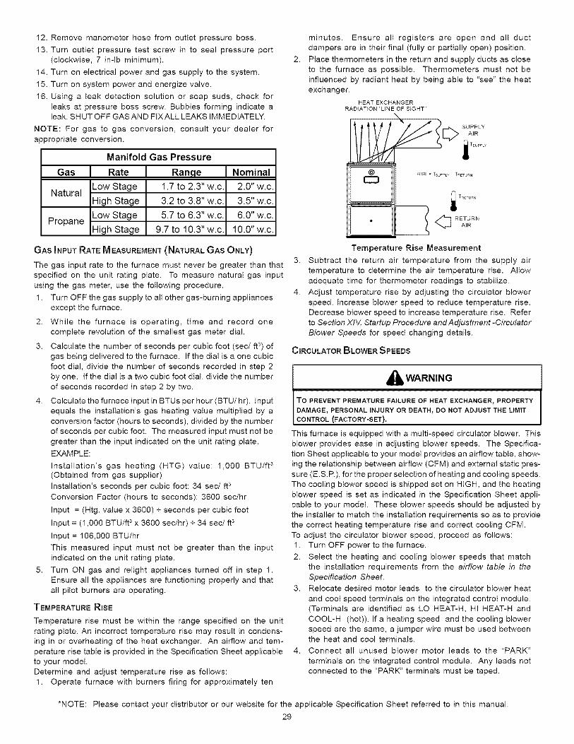
12. Remove manometer hose from outlet pressure boss.
13. Turn outlet pressure test screw in to seal pressure port
(clockwise, 7 in-lb minimum).
14. Turn on electrical power and gas supply to the system.
15. Turn on system power and energize valve.
16. Using a leak detection solution or soap suds, check for
leaks at pressure boss screw. Bubbles forming indicate aleak. SHUT OFF GASAND FIXALL LEAKS IMMEDIATELY.
NOTE: For gas to gas conversion, consult your dealer for
appropriate conversion.
Manifold Gas Pressure
Gas Rate
Low StageNatural
High Stage
Low StagePropane
High Stage
Range1.7 to 2.3" w.c.
3.2 to 3.8" w.c.
5.7 to 6.3" w.c.
9.7 to 10.3" w.c.
Nominal
2.0" w.c.
3.5" w.c.
6.0" w.c.
10.0" w.c.
GAS INPUT RATE MEASUREMENT (NATURAL GAS ONLY)
The gas input rate to the furnace must never be greater than that
specified on the unit rating plate. To measure natural gas input
using the gas meter, use the following procedure.
1. Turn OFF the gas supply to all other gas-burning appliances
except the furnace.
2. While the furnace is operating, time and record onecomplete revolution of the smallest gas meter dial.
3. Calculate the number of seconds per cubic foot (sec/ft 3) ofgas being delivered to the furnace. If the dial is a one cubic
foot dial, divide the number of seconds recorded in step 2
by one. If the dial is a two cubic foot dial, divide the number
of seconds recorded in step 2 by two.
4. Calculate the furnace input in BTUs per hour (BTU/hr). Input
equals the installation's gas heating value multiplied by a
conversion factor (hours to seconds), divided by the numberof seconds per cubic foot. The measured input must not be
greater than the input indicated on the unit rating plate.
EXAMPLE:
Installation's gas heating (HTG) value: 1,000 BTU/ft 3(Obtained from gas supplier)
Installation's seconds per cubic foot: 34 sec/ft s
Conversion Factor (hours to seconds): 3600 sec/hr
Input = (Htg. value x 3600) + seconds per cubic foot
Input = (1,000 BTU/ft s x 3600 sec/hr) + 34 sec/ft s
Input = 106,000 BTU/hr
This measured input must not be greater than the input
indicated on the unit rating plate.
5. Turn ON gas and relight appliances turned off in step 1.
Ensure all the appliances are functioning properly and that
all pilot burners are operating.
TEMPERATURE RISE
Temperature rise must be within the range specified on the unit
rating plate. An incorrect temperature rise may result in condens-
ing in or overheating of the heat exchanger. An airflow and tem-
perature rise table is provided in the Specification Sheet applicableto your model.
Determine and adjust temperature rise as follows:
1. Operate furnace with burners firing for approximately ten
2.
minutes. Ensure all registers are open and all duct
dampers are in their final (fully or partially open) position.
Place thermometers in the return and supply ducts as close
to the furnace as possible. Thermometers must not be
influenced by radiant heat by being able to "see" the heat
exchanger.
HEAT EXCHANGERRADIATION "LINE OF SIGHT"
i TRETUR_
l <bRETURN
4.
Temperature Rise Measurement
Subtract the return air temperature from the supply air
temperature to determine the air temperature rise. Allow
adequate time for thermometer readings to stabilize.
Adjust temperature rise by adjusting the circulator blower
speed. Increase blower speed to reduce temperature rise.
Decrease blower speed to increase temperature rise. Refer
to Section XIV, Startup Procedure and Adjustment -CirculatorBlower Speeds for speed changing details.
CIRCULATOR BLOWER SPEEDS
_i, WARNING
TO PREVENT PREMATURE FAILURE OF HEAT EXCHANGER, PROPERTY
DAMAGEr PERSONAL INJURY OR DEATH, DO NOT ADJUST THE LIMITCONTROL (FACTORY-SET).
This furnace is equipped with a multi-speed circulator blower. Thisblower provides ease in adjusting blower speeds. The Specifica-
tion Sheet applicable to your model provides an airflow table, show-
ing the relationship between airflow (CFM) and external static pres-
sure (E.S.R), for the proper selection of heating and cooling speeds.
The cooling blower speed is shipped set on HIGH, and the heating
blower speed is set as indicated in the Specification Sheet appli-cable to your model. These blower speeds should be adjusted by
the installer to match the installation requirements so as to provide
the correct heating temperature rise and correct cooling CFM.
To adjust the circulator blower speed, proceed as follows:1. Turn OFF power to the furnace.
2. Select the heating and cooling blower speeds that matchthe installation requirements from the airflow table in the
Specification Sheet.
3. Relocate desired motor leads to the circulator blower heat
and cool speed terminals on the integrated control module.
(Terminals are identified as LO HEAT-H, HI HEAT-H and
COOL-H (hot)). If a heating speed and the cooling blower
speed are the same, a jumper wire must be used betweenthe heat and cool terminals.
4. Connect all unused blower motor leads to the "PARK"
terminals on the integrated control module. Any leads notconnected to the "PARK" terminals must be taped.
*NOTE: Please contact your distributor or our website for the applicable Specification Sheet referred to in this manual.
29
5,
6.
Turn ON power to furnace.
Verify proper temperature rise as outlined in Section XIV,Startup Procedure and Adjustment - Temperature Rise.
Circulator Blower SpeedsLow Red
Medium Low OrangeMedium Blue
High BlackCommon/Neutral White
XV. NORMAL SEQUENCE OF OPERATION
POWER UP
The normal power up sequence is as follows:
° 115 VAC power applied to furnace.
• Integrated control module performs internal checks.
° Integrated control module LED will light.
• Integrated control module monitors safety circuits
continuously.
° Furnace awaits call from thermostat.
HEATING MODE
(MODE DiP SWITCH IS SET TO "1 STG" POSITION)
The normal operational sequence in heating mode is as follows:
° R and W thermostat contacts close, initiating a call for heat.
• integrated control module performs safety circuit checks.
° induced draft blower is energized for 15 second pre-purge
period causing pressure switch contacts to close.
• igniter warm up begins after 15 second prepurge expires.
° Low and high stage gas valves open at end of igniter warm
up period, delivering gas to burners and establishing flame.
• integrated control module monitors flame presence. Gas
valve will remain open only if flame is detected.
• Circulator blower is energized on high heat speed following
a fixed thirty second blower on delay. Electronic air cleaner
terminals are energized with circulator blower.
• Furnace operates; integrated control module monitors
safety circuits continuously.
° R and W thermostat contacts open, completing the call for
heat.
° Gas valve closes, extinguishing flame.
° Induced draft blower is de-energized following a fifteen
second post purge.
The circulator blower remains at high heat speed for thirtyseconds. The circulator blower then switches to low heat
speed for the remainder of the selected heat off delay period.
For example, the selected heat off delay period is 150
seconds. The circulator blower operates at high heat for 30
seconds and at low speed for 150 - 30 = 120 seconds.
(MODE DiP SWITCH IS SET TO "2 STG" POSITION)
The normal operational sequence in sequence is as follows:
• R and W thermostat contacts close, initiating a call for heat.
° integrated control module performs safety circuit checks.
• induced draft blower is energized for 15 second prepurge
period causing pressure switch contacts to close.
Igniter warm up begins after 15 second prepurge expires.
° Low and high-stage gas valves open at end of igniter warm
up period, delivering gas to burners and establishing flame.
High-stage gas valve closes after five seconds; low-stage
gas valve remains open.
Integrated control module monitors flame presence. Gas
valve will remain open only if flame is detected.
° Circulator blower is energized on low heat speed following
a fixed thirty second blower on delay. Electronic air cleaner
terminals are energized with circulator blower.
° Furnace is now operating in low-stage heating mode.
Furnace operates; integrated control module monitors
safety circuits continuously.
° If low-stage delay period expires, control will shift operation
from low-stage heating mode operation to high-stage
heating mode operation. Control will energize circulator
blower high heat speed and high stage gas valve.
Furnace is now operating in high-stage heating mode.
° R and W thermostat contacts open, completing the call for
heat.
Induced draft blower is de-energized following a fifteen
second post purge.
Circulator blower is de-energized following a heat off delay
period (selectable 100 or 150 seconds; factory set at 150seconds).
If the furnace is operating in the low-stage heating modewhen thermostat contacts open, circulator remains at low
heat speed for the selected delay off period.
If the furnace is operating in high-stage heating mode when
the thermostat contacts open, the circulator blower remains
at high heat speed for thirty seconds. The circulator blower
then switches to low heat speed for the remainder of the
selected heat off delay period. For example, the selected
heat off delay period is 150 seconds. The circulator bloweroperates at high heat for 30 seconds and at low speed for150 - 30 = 120 seconds.
Furnace awaits the next call from thermostat.
o
3O
COOLING MODE
The normal operational sequence in cooling mode is as follows:
R and Y thermostat contacts close, initiating a call for cool.
° Integrated control module performs safety circuit checks.
Outdoor fan and compressor are energized.
Circulator blower is energized on cool speed following a
fixed five second on delay. Electronic air cleaner terminalsare energized with circulator blower.
Furnace circulator blower and outdoor cooling unit run,
integrated control module monitors safety circuits
continuously.
R and Y thermostat contact open, completing the call forcool.
Outdoor fan and compressor are de-energized.
° Circulator blower is de-energized following a fixed forty five
second cool off delay period. Electronic air cleaner terminals
are de-energized.
Furnace awaits the next call from thermostat.
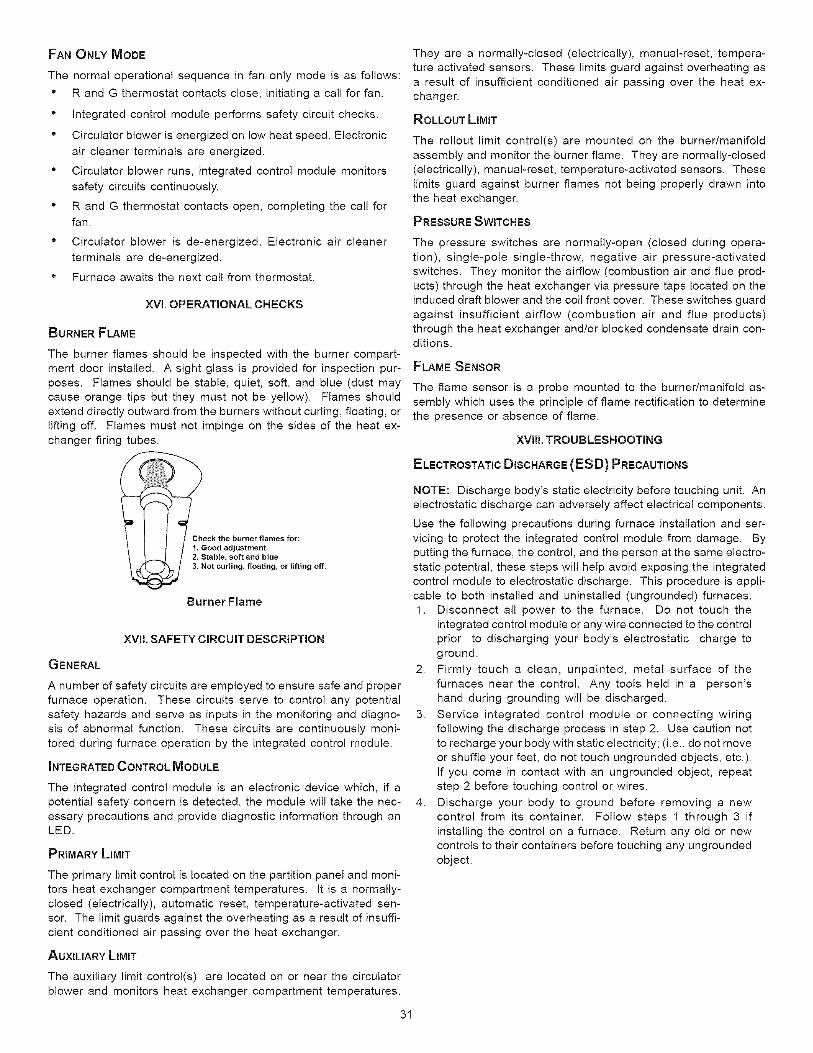
FANONLYMODE
The normal operational sequence in fan only mode is as follows:
" R and G thermostat contacts close, initiating a call for fan.
• Integrated control module performs safety circuit checks.
" Circulator blower is energized on low heat speed. Electronic
air cleaner terminals are energized.
• Circulator blower runs, integrated control module monitors
safety circuits continuously.
• R and G thermostat contacts open, completing the call for
fan.
" Circulator blower is de-energized. Electronic air cleaner
terminals are de-energized.
• Furnace awaits the next call from thermostat.
XVl. OPERATIONAL CHECKS
BURNER FLAME
The burner flames should be inspected with the burner compart-
ment door installed. A sight glass is provided for inspection pur-
poses. Flames should be stable, quiet, soft, and blue (dust may
cause orange tips but they must not be yellow). Flames should
extend directly outward from the burners without curling, floating, orlifting off. Flames must not impinge on the sides of the heat ex-
changer firing tubes.
Check the burner flames for:
1. Good adjustment2, Stable, soft and blue3, Not curling, floating, or lifting off.
Burner Flame
XVlI. SAFETY CIRCUIT DESCRIPTION
GENERAL
A number of safety circuits are employed to ensure safe and proper
furnace operation. These circuits serve to control any potential
safety hazards and serve as inputs in the monitoring and diagno-sis of abnormal function. These circuits are continuously moni-
tored during furnace operation by the integrated control module.
_NTEGRATED CONTROL MODULE
The integrated control module is an electronic device which, if apotential safety concern is detected, the module will take the nec-
essary precautions and provide diagnostic information through anLED.
PRIMARY LIMIT
The primary limit control is located on the partition panel and moni-
tors heat exchanger compartment temperatures. It is a normally-
closed (electrically), automatic reset, temperature-activated sen-sor. The limit guards against the overheating as a result of insuffi-
cient conditioned air passing over the heat exchanger.
AUXILIARY LIMIT
The auxiliary limit control(s) are located on or near the circulator
blower and monitors heat exchanger compartment temperatures.
31
They are a normally-closed (electrically), manual-reset, tempera-
ture activated sensors. These limits guard against overheating as
a result of insufficient conditioned air passing over the heat ex-
changer.
ROLLOUT LIMIT
The rollout limit control(s) are mounted on the burner/manifold
assembly and monitor the burner flame. They are normally-closed
(electrically), manual-reset, temperature-activated sensors. These
limits guard against burner flames not being properly drawn intothe heat exchanger.
PRESSURE SWITCHES
The pressure switches are normally-open (closed during opera-
tion), single-pole single-throw, negative air pressure-activatedswitches. They monitor the airflow (combustion air and flue prod-
ucts) through the heat exchanger via pressure taps located on the
induced draft blower and the coil front cover. These switches guard
against insufficient airflow (combustion air and flue products)through the heat exchanger and/or blocked condensate drain con-ditions.
FLAME SENSOR
The flame sensor is a probe mounted to the burner/manifold as-sembly which uses the principle of flame rectification to determine
the presence or absence of flame.
XVlll. TROUBLESHOOTING
ELECTROSTATIC DISCHARGE (ESD) PRECAUTIONS
NOTE: Discharge body's static electricity before touching unit. An
electrostatic discharge can adversely affect electrical components.
Use the following precautions during furnace installation and ser-
vicing to protect the integrated control module from damage. By
putting the furnace, the control, and the person at the same electro-
static potential, these steps will help avoid exposing the integratedcontrol module to electrostatic discharge. This procedure is appli-
cable to both installed and uninstalled (ungrounded) furnaces.
1. Disconnect all power to the furnace. Do not touch the
integrated control module or any wire connected to the controlprior to discharging your body's electrostatic charge to
ground.
2. Firmly touch a clean, unpainted, metal surface of thefurnaces near the control. Any tools held in a person's
hand during grounding will be discharged.
3. Service integrated control module or connecting wiringfollowing the discharge process in step 2. Use caution not
to recharge your body with static electricity; (i.e., do not move
or shuffle your feet, do not touch ungrounded objects, etc.).
If you come in contact with an ungrounded object, repeatstep 2 before touching control or wires.
4. Discharge your body to ground before removing a newcontrol from its container. Follow steps 1 through 3 if
installing the control on a furnace. Return any old or new
controls to their containers before touching any ungrounded
object.
DIAGNOSTICCHART
d_lb WARNING
HIGH VOLTAGE! _
To AVOID PERSONAL INJURY OR DEATH DUE TO
ELECTRICAL SHOCK_ DISCONNECT ELECTRICAL POWERBEFORE PERFORMAING ANY SERVICE OR MAINTENANCE.
Refer to the Troubleshooting Chart at the end of this manual for
assistance in determining the source of unit operational problems.
The red diagnostic LED blinks to assist in troubleshooting the unit.
The number of blinks refers to a specific fault code.
FAULT RECALL
The ignition control is equipped with a momentary pushbutton
switch that can be used to display on the diagnostic LED the last
five faults detected by the control. The control must be in Standby
Mode (no thermostat inputs) to use the feature. Depress the
pushbutton switch for approximately 2 seconds. Release the switch
when the LED is turned off. The diagnostic LED will then displaythe flash codes associated with the last five detected faults. The
order of display is the most recent fault to the least recent fault.
RESETTING FROM LOCKOUT
Furnace lockout results when a furnace is unable to achieve igni-tion after three attempts during a single call for heat. It is character-
ized by a non-functioning furnace and a one flash diagnostic LED
code. If the furnace is in "lockout", it will (or can be) reset in any of
the following ways.1. Automatic reset. The integrated control module will
automatically reset itself and attempt to resume normal
operations following a one hour lockout period.
2. Manual power interruption. Interrupt 115 volt power to thefurnace for 1 - 20 seconds.
3. Manual thermostat cycle. Lower the thermostat so that
there is no longer a call for heat then reset to previous setting.
Interrupt thermostat signal to the furnace for 1 - 20 seconds.
NOTE: If the condition which originally caused the lockout stillexists, the control will return to lockout. Refer to Section XVIII,
Troubleshooting - Diagnostic Chart for aid in determining the cause.
XlX. MAINTENANCE
_'_ WARNING
HIGH VOLTAGE!To AVOID PERSONAL INJURY OR DEATH DUE TO
ELECTRICAL SHOCK, DISCONNECT ELECTRICAL POWER _ e
BEFORE PERFORMING ANY MAINTENANCE. _FYOU MUST
HANDLE THE IGNITER_HANDLE WITH CARE. TOUCHINGTHE IGNITER ELEMENT WITH BARE FINGERS_ ROUGHHANDLING OR VIBRATION COULD DAMAGE THE IGNITERRESULTING IN PREMATURE FAILURE. ONLY A QUALIFIEDSERVICER SHOULD EVER HANDLE THE IGNITER.
ANNUAL INSPECTION
The furnace should be inspected by a qualified installer, or serviceagency at least once per year. This check should be performed at
the beginning of the heating season. This will ensure that all fur-
nace components are in proper working order and that the heating
system functions appropriately. Pay particular attention to the fol-
lowing items. Repair or service as necessary.
° Flue pipe system. Check for blockage and/or leakage. Check
the outside termination and the connections at and internal
to the furnace.
° Heat exchanger. Check for corrosion and/or buildup within
the heat exchanger passageways.
° Burners. Check for proper ignition, burner flame, and flame
sense.
° Drainage system. Check for blockage and/or leakage.
Check hose connections at and internal to furnace.
" Wiring. Check electrical connections for tightness and/or
corrosion. Check wires for damage.
" Filters.
FILTERS
_ CAUTION
To ENSURE PROPER UNIT PERFORMANCE, ADHERE TO THE FILTER
SIZES GIVEN IN THE RECOMMENDED MINIMUM FILTER SIZE TABLE OR
SPECIFICATION SHEET APPLICABLE TO YOUR MODEL*
MAINTENANCE
Improper filter maintenance is the most common cause of inad-
equate heating or cooling performance. Filters should be cleaned
(permanent) or replaced (disposable) every two months or as re-
quired. When replacing a filter, it must be replaced with a filter ofthe same type and size.
FILTER REMOVAL
Depending on the installation, differing filter arrangements can be
applied. Filters can be installed in either the central return register
or a side panel external filter rack (upflow only). A media air filter orelectronic air cleaner can be used as an alternate filter. Follow the
filter sizes given in the Recommended Minimum Filter size table to
ensure proper unit performance.
To remove filters from an external filter rack in an upright upflow
installation, follow the directions provided with external filter rackkit. To remove internal filters see Internal Filter Removal section.
Internal filters are an accessory item and are not included with
your furnace. For further details, see your distributor.
HORIZONTALUNITFILTERREMOVAL
Filters in horizontal installations are located in the central return
register or the ductwork near the furnace.To remove:
1. Turn OFF electrical power to furnace.
2. Remove filter(s) from the central return register or ductwork.
3. Replace filter(s) by reversing the procedure for removal.
4. Turn ON electrical power to furnace.
MED_ AJ_FILTF_ _ E_ AJI!LC_ REMDJ[_.
Follow the manufacturer's directions for service.
BURNERS
Visually inspect the burner flames periodically during the heatingseason. Turn on the furnace at the thermostat and allow several
minutes for flames to stabilize, since any dislodged dust will alter
the flames normal appearance. Flames should be stable, quiet,
soft, and blue (dust may cause orange tips but they must not be
yellow). They should extend directly outward from the burners with-
*NOTE: Please contact your distributor or our website for the applicable Specification Sheet referred to in this manual.
32
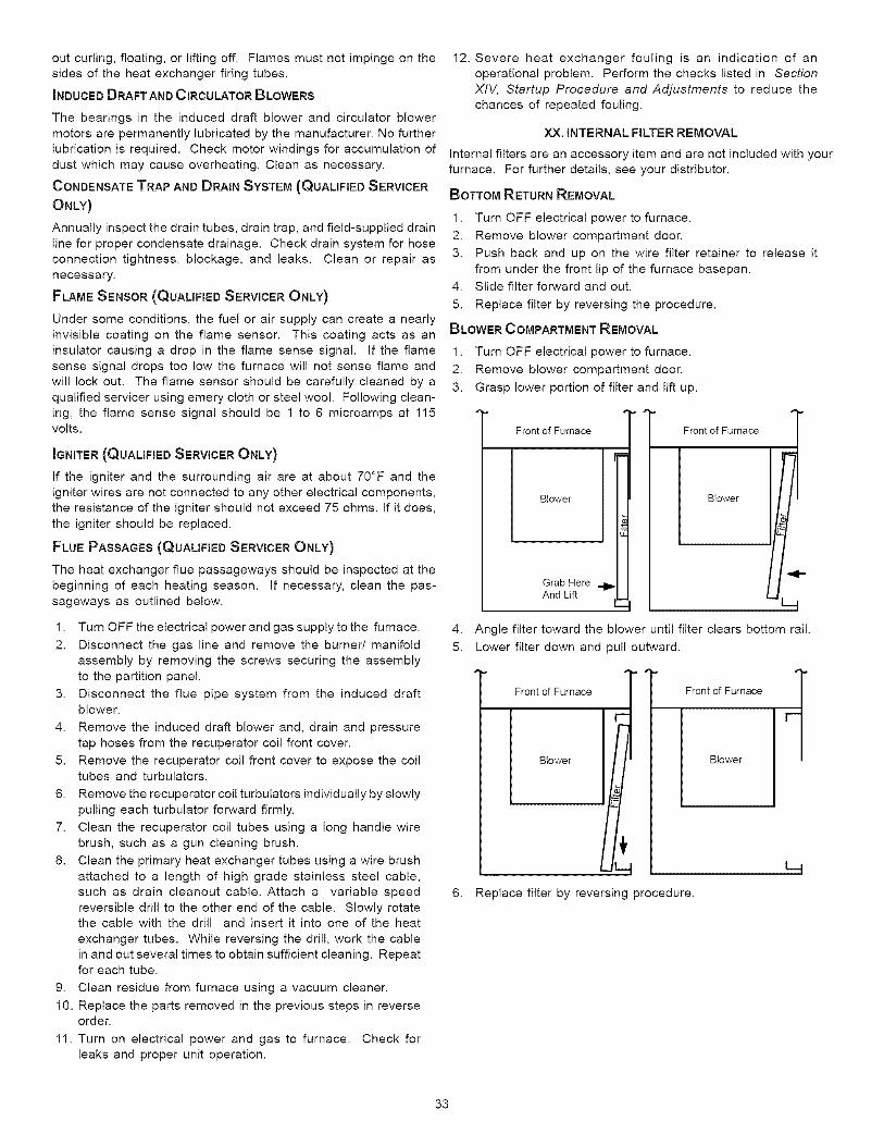
outcurling,floating,orliftingoff.Flamesmustnotimpingeonthesidesoftheheatexchangerfiringtubes.INDUCEDDRAFTANDCIRCULATORBLOWERSThebearingsin theinduceddraftblowerandcirculatorblowermotorsarepermanentlylubricatedbythemanufacturer.Nofurtherlubricationisrequired.Checkmotorwindingsforaccumulationofdustwhichmaycauseoverheating.Cleanasnecessary.CONDENSATE TRAP AND DRAIN SYSTEM (QUALIFIED SERVICER
ONLY)
Annually inspect the drain tubes, drain trap, and field-supplied drain
line for proper condensate drainage. Check drain system for hoseconnection tightness, blockage, and leaks. Clean or repair as
necessary.
FLAME SENSOR (QUALIFIED SERVICER ONLY)
Under some conditions, the fuel or air supply can create a nearly
invisible coating on the flame sensor. This coating acts as aninsulator causing a drop in the flame sense signal. If the flame
sense signal drops too low the furnace will not sense flame and
will lock out. The flame sensor should be carefully cleaned by a
qualified servicer using emery cloth or steel wool. Following clean-
ing, the flame sense signal should be 1 to 6 microamps at 115volts.
IGNITER (QUALIFIED SERVICER ONLY)
If the igniter and the surrounding air are at about 70°F and the
igniter wires are not connected to any other electrical components,the resistance of the igniter should not exceed 75 ohms. If it does,
the igniter should be replaced.
FLUE PASSAGES (QUALIFIED SERVICER ONLY)
The heat exchanger flue passageways should be inspected at the
beginning of each heating season. If necessary, clean the pas-
sageways as outlined below.
1. Turn OFF the electrical power and gas supply to the furnace.
2. Disconnect the gas line and remove the burner/ manifold
assembly by removing the screws securing the assembly
to the partition panel.
3. Disconnect the flue pipe system from the induced draftblower.
4. Remove the induced draft blower and, drain and pressure
tap hoses from the recuperator coil front cover.
5. Remove the recuperator coil front cover to expose the coiltubes and turbulators.
6. Remove the recuperator coil turbulators individually by slowly
pulling each turbulator forward firmly.
7. Clean the recuperator coil tubes using a long handle wire
brush, such as a gun cleaning brush.
8. Clean the primary heat exchanger tubes using a wire brush
attached to a length of high grade stainless steel cable,such as drain cleanout cable. Attach a variable speed
reversible drill to the other end of the cable. Slowly rotatethe cable with the drill and insert it into one of the heat
exchanger tubes. While reversing the drill, work the cable
in and out several times to obtain sufficient cleaning. Repeatfor each tube.
9. Clean residue from furnace using a vacuum cleaner.
10. Replace the parts removed in the previous steps in reverseorder.
11. Turn on electrical power and gas to furnace. Check for
leaks and proper unit operation.
12. Severe heat exchanger fouling is an indication of an
operational problem. Perform the checks listed in Section
>(IV, Startup Procedure and Adjustments to reduce the
chances of repeated fouling.
XX. INTERNAL FILTER REMOVAL
Internal filters are an accessory item and are not included with yourfurnace. For further details, see your distributor.
BOTTOM RETURN REMOVAL
1. Turn OFF electrical power to furnace.
2. Remove blower compartment door.
3. Push back and up on the wire filter retainer to release it
from under the front lip of the furnace basepan.
4. Slide filter forward and out.
5. Replace filter by reversing the procedure.
BLOWER COMPARTMENT REMOVAL
1. Turn OFF electrical power to furnace.
2. Remove blower compartment door.
3. Grasp lower portion of filter and lift up.
Front of Furnace
Blower
Grab HereAnd Lift
Front of Furnace
4. Angle filter toward the blower until filter clears bottom rail.
5. Lower filter down and pull outward.
Front of Furnace
Blower
Front of Furnace
Blower
L4
6. Replace filter by reversing procedure.
33
XXL BEFORE LEAVING AN INSTALLATION
• Cycle the furnace with the thermostat at least three times.
Verify cooling and fan only operation.
" Review the Owner's Manual with the homeowner and
discuss proper furnace operation and maintenance.
" Leave literature packet near furnace.
XXII, REPAIR & REPLACEMENT PARTS
" When ordering any of the listed functional parts, be sure to
provide the furnace model, manufacturing, and serialnumbers with the order.
" Although only functional parts are shown in the parts list, all
sheet metal parts, doors, etc. may be ordered by description.
" Parts are available from your distributor.
Functional Parts List-Gas ValveGas ManifoldNatural Gas Orifice
Propane Gas OrificeIgniterFlame SensorRollout Limit Switch
Primary Limit SwitchAuxiliary Limit SwitchPressure SwitchInduced Draft BlowerDoor Switch
Blower Motor
Blower Wheel
Blower Mounting BracketBlower Cutoff
Blower HousingCapacitor
Heat ExchangerCoil Front Cover
Integrated Control ModuleTransformer
34
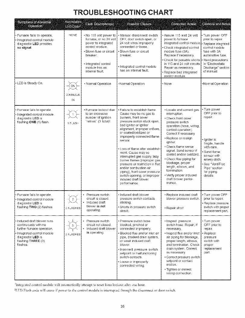
, Furnace fails to operate.
, Integrated control modulediagnostic LED providesno signal.
, LED is Steady On.
, Furnace fails to operate.
, Integrated control modulediagnostic LED isflashing ONE (1) flash.
, Furnace fails to operate.
, Integrated control modulediagnostic LED isflashing TWO (2) flashes.
, Induced draft blower runs
continuously with nofurther furnace operation.
, Integrated control modulediagnostic LED isflashing THREE (3)flashes.
TROUBLESHOOTING CHART
NONE
CONTINUOUS
ON
FLASH
2 FLASHES
3 FLASHES
No 115 volt power tofurnace, or no 24 volt)ower to integrated
control module.
Blown fuse or circuitbreaker.
Integrated controlmodule has aninternal fault.
• Normal Operation
Furnace lockout dueto an excessive
number of ignition"retries" (3 totat)L
Pressure switchcircuit is closed.Induced draftblower is not
operating.
Pressure switchcircuit not closed.Induced draft blower
is operating.
Manual disconnect switch
OFF, door switch open, or24 volt wires improperlyconnected or loose.
Blown fuse or circuitbreaker.
Integrated control modulehas an internal fault.
•Normal Operation
Failure to establish flame.Cause may be no gas toburners, front coverpressure switch stuck open,bad igniter or igniteralignment, improper orifices,or coated/oxidized or
improperly connected flamesensor.
. Loss of flame after establish-
ment. Cause may beinterrupted gas supply, lazyburner flames (improper gaspressure or restriction in flueand/or combustion air
piping), front cover pressureswitch opening, or improperinduced draft blower
performance.
. Induced draft blower
pressure switch contactssticking.
. Shorts in pressure switchcircuit.
Pressure switch hose
blocked, pinched orconnected improperly.Blocked flue and/or inlet air
pipe, blocked drain system,or weak induced draftblower.
. Incorrect pressure switchsetpoint or malfunctioningswitch contacts.
. Loose or improperlyconnected wiring.
*Assure 115 and 24 volt
power to furnaceintegrated control module
. Check integrated controlmodule fuse (3A).Replace if necessary.
. Check for possible shortsin 115 and 24 volt circuits
Repair as necessary.
. Replace bad integratedcontrol module.
. Locate and correct gasinterruption.
. Check front cover
pressure switchoperation (hose, wiring,contact operation).Correct if necessary.
. Replace or realignigniter.
. Check flame sense
signal. Sand sensor ifcoated and/or oxidized.
. Check flue piping forblockage, properlength, elbows, andtermination.
. Verify proper induceddraft blower perfor-mance.
. Replace induced draftblower pressure switch.
. Repair short.
. Inspect pressureswitch hose. Repair, ifnecessary,
. Inspect flue and/or inletair piping for blockage,proper length, elbows,and termination. Check
drain system. Correctas necessary.
. Correct pressure switchsetpoint or contactmotion.
. Tighten or correctwiring connection.
* None
• Turn power OFFprior to repair.
• Replace integratedcontrol modulefuse with 3Aautomotive fuse.
• Read precautionsin "Electrostatic
Discharge" sectionof manual.
•Normal Operation
• Turn powerOFF prior torepair.
Igniter isfragile, handlewith care.
Sand flamesensor with
emery cloth.See "Vent/Flue
Pipe" sectionfor pipingdetails.
• Turn power OFFprior to repair.
Replace pressureswitch with properreplacement part.
Turn powerOFF prior torepair.
Replace)ressure
switch with
properreplacement)art.
iIntegrated control module will automatically attempt to reset from lockout after one hour.
2LED Flash code will cease if power to the control module is interrupted through the disconnect or door switch.
35
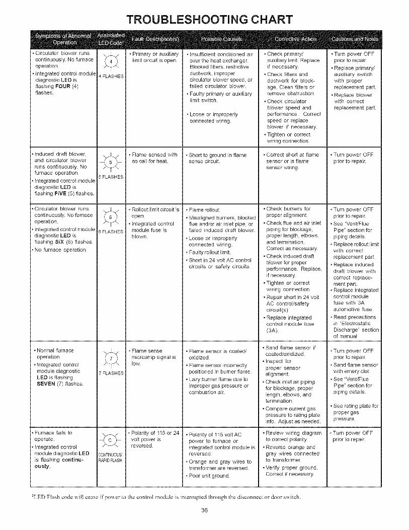
• Circulator blower runs
continuously. No furnaceoperation.
• Integrated control modulediagnostic LED isflashing FOUR (4)flashes.
• Induced draft blower,and circulator blowerruns continuously. Nofurnace operation.
• Integrated control modulediagnostic LED isflashing FIVE (5) flashes.
• Circulator blower runs
continuously. No furnaceoperation.
• Integrated control modulediagnostic LED isflashing SIX (6) flashes.
• No furnace operation,
• Normal furnaceoperation.
• Integrated controlmodule diagnosticLED is flashingSEVEN (7) flashes.
• Furnace fails to
operate.
• Integrated controlmodule diagnostic LEDis flashing continu-ously.
TROUBLESHOOTING CHART
E
4 FLASHES
÷5 FLASHES
÷6 FLASHES
° Primary or auxiliarylimit circuit is open.
÷
• Flame sensed withno call for heat.
* Rollout limit circuit is
open.
° Integrated controlmodule fuse isblown.
° Flame sense
microamp signal istOW.
7 FLASHES
* Polarity of 115 or 24volt power isreversed.÷
,?,ONTINUOUS/
RAPID FLASH
• Insufficient conditioned air
over the heat exchanger.Blocked filters, restrictiveductwork, impropercirculator blower speed, orfailed circulator blower.
• Faulty primary or auxiliarylimit switch.
• Loose or improperlyconnected wiring.
* Short to ground in flamesense circuit.
* Flame ro!lout.
* Misaligned burners, blockedflue and/or air inlet pipe, orfailed induced draft blower.
* Loose or improperlyconnected wiring.
* Faulty rollout limit.
* Short in 24 volt AC control
circuits or safety circuits.
* Flame sensor is coated/oxidized.
* Flame sensor incorrectlypositioned in burner flame.
* Lazy burner flame due toimproper gas pressure orcombustion air.
* Polarity of 1I5 volt ACpower to furnace orintegrated control module isreversed.
* Orange and gray wires totransformer are reversed.
* Poor unit ground.
* Check primary/auxiliary limit. Replaceif necessary.
* Check filters andductwork for block-
age. Clean filters orremove obstruction.
* Check circulator
blower speed andperformance. Correctspeed or replaceblower if necessary.
* Tighten or correctwiring connection.
* Correct short at flamesensor or in flame
sensor wiring.
• Check burners for
proper alignment.• Check flue and air inlet
piping for blockage,proper length, elbows,and termination.
Correct as necessary.• Check induced draft
blower for properperformance. Replace,if necessary.
• Tighten or correctwiring connection.
• Repair short in 24 voltAC control/safetycircuit(s)
• Replace integratedcontrol module fuse
(3A).
• Sand flame sensor ifcoated/oxidized.
• Inspect forproper sensoralignment.
• Check inlet air pipingfor blockage, properlength, elbows, andtermination.
• Compare current gaspressure to rating plateinfo. Adjust as needed.
• Review wiring diagramto correct polarity.
• Reverse orange andgray wires connectedto transformer.
• Verify proper ground.Correct if necessary.
• Turn power OFFprior to repair.
• Replace primary/auxiliary switchwith properreplacement part.
• Replace blowerwith correct
replacement part.
. Turn power OFFprior to repair.
. Turn power OFFprior to repair.
. See "Vent/Flue
Pipe" section forpiping details.
. Replace rollout limitwith correct
replacement part.
• Replace induceddraft blower with
correct replace-ment part.
. Replace integratedcontrol modulefuse with 3Aautomotive fuse.
. Read precautionsin "Electrostatic
Discharge" sectionof manual
. Turn power OFFprior to repair.
. Sand flame sensor
with emery clot.. See "Vent/Flue
Pipe" section forpiping details.
. See rating plate forproper gaspressure.
. Turn power OFFprior to repair.
2LED Flash code will cease if power to the control module is interrupted through the disconnect or door switch.
36
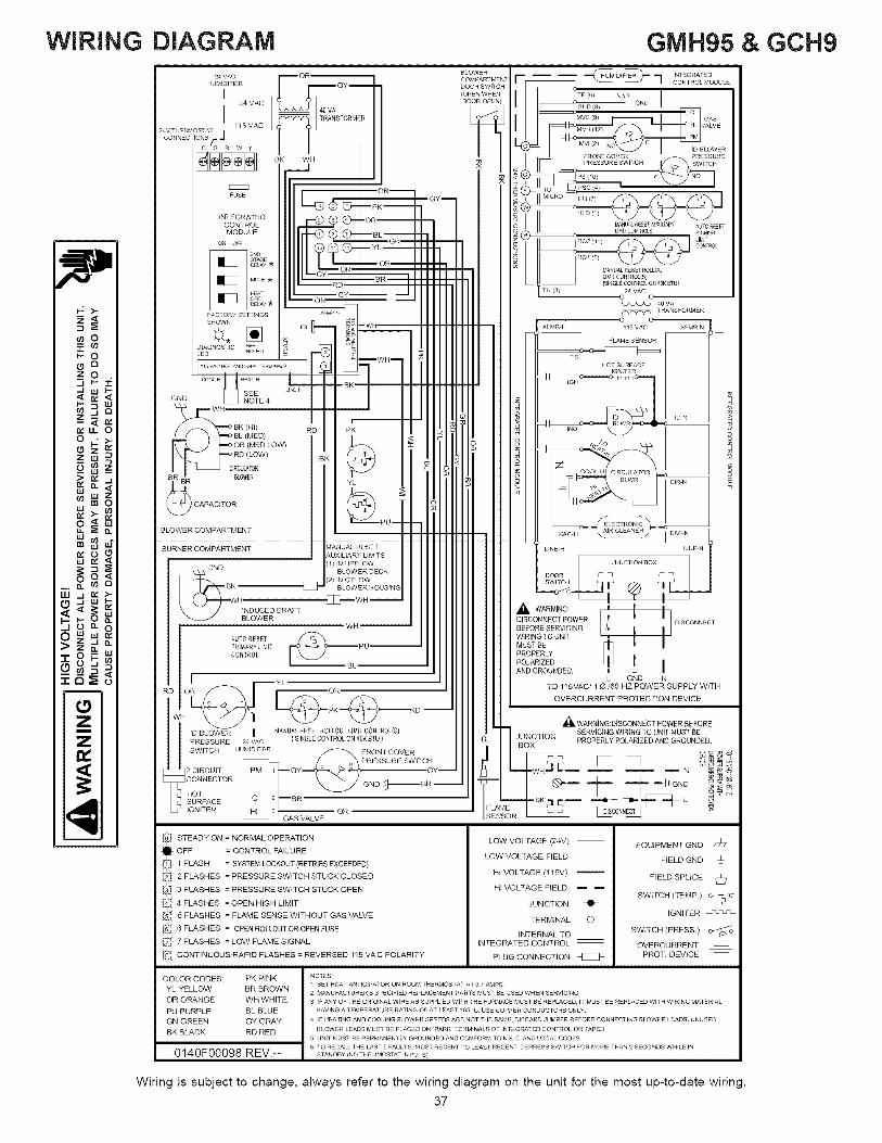
WiRiNG DIAGRAM GMH95 & GCH9
Z
z
BK WHco I PRESSUR_ SW_rCH SWale t
__ 00 ,_ I PS (101 C NO
IORI m (_ lo
IIII_--_© C_----PK--- i I i_L_ .INTEGRATED "ORI - --
MODULE |III_ ¢_ (h----BL-- -- I _ _o_ _ot_ _._e,o, oF IIIIIII _ _--GR .... .ilii I I_ RO2(11) _ _ I I_11IIIIIII ..... .......,_. --OR.... :.11 I1_
I IIIII L_'T--°P, _.. , I I I ,_,Y_._,,%',;......,_oo_.IIII_ _" i i i i i _ :SINGLEOONTROLON4:KBTU}
_ TRANSFORMER
._. : I FS ht"-- _ ...... "T'TT -1 I I XFMR'H 115VAC XYlvlR'N
_. _ I_ _ III /11 _ ........... •DIAGNOSTIC s_ ,_ _L_D "°T_ I_ -_ _ _ III /11 I
i WH :_ _s H01 SURFACE__ III /11 I ....... /_----BR ....... H /11 _ /_
GND _ NOTE4 I II / I I _ I /WN __L_.,.., _i__ Itl /I I_ __ .... /
_RDPK -< oBL (MED) m o_OR,MED_OW,_. _ lil /11o _L_o_._ I_
Iq..__ _l°RD(LOW) BK (-_ o I1_ /I I_ _"__ /_CIRGJMTOR m O _ Ioo L H 0_
___ _ III /11_ _ #_ ...... /_BLOWER COMPARTMENT ,ACH \ " / BACN
GND (1) INLUPFLOV_ EC K ............
_LO_R,ou.... ___o_.__3 €Hill WH -
k _ // INDUCED DRAFT III H I _, WARNING:
BLOWER DISCONNECT POWER I I DISCONNEC]--wR-- III H / O_FO_SR_VONGIAUTO RE%T WIRING TO UNIT I IP/qMAiiY'i l,, IT _PU I III II/l_usTOE $ I ICONTROL PROPERLYB_-- IIIIIII_o_'_O_OED,__ I
YL L GND N
RD OR OR T00 1V15_uCR 1 _ N 6TO##oPOZTEoRS DU_VPLY2IT H
DBLOWER I _ T o%:M-CONJROL(SJ I ' T JUNCTION SERVICING.WIRiNGTOUNITMUSTBEPRESSURE 24VAC ( SINGLE CGNTRO_ON Z_rKFU ) I BL I _v PROPERLY POLARIZED AND GROUNDED.
SWITCH HUMIDIFIER _HvJFRONT COVER _1 I _A L_ _ _ 22' _ __ o _
2 CIRCUIT PM I i GY GY L_ I _ .WH,.I I,,, ..... N _ _
CONNECTOR _1 I _ _ _
_oE_E_DEc _--BR-- -- - C....-0_., ,..-- _ ,4.....L_ IGNITER HI 3 1 OR I FLAME _ _' i _SOONNECTj
GAS VALVE USENSORA r.
_ TEADY ON = NORMAL OPERATION
OFF = CONTROL FAILURE
1 FLASH = SYSTEM LOCKOUT (RETRIES EXCEEDED)
2 FLASHES = PRESSURE SWITCH STUCK CLOSED
3 FLASHES = PRESSURE SWITCH STUCK OPEN
4 FLASHES = OPEN HIGH LIMIT
5 FLASHES = FLAME SENSE WITHOUT GAS VALVE
6 FLASHES = OPEN ROLLOUT OR OPEN FUSE
7 FLASHES = LOW FLAME SIGNAL
CONTINUOUS RAPID FLASHES = REVERSED 115 VA C POLARITY
LOW VOLTAGE (24V)
LOW VOLTAGE FIELD
HI VOLTAGE (115V)
HI VOLTAGE FIELD _
JUNCTION _1_
TERMINAL
iNTERNAL TO
INTEGRATED CONTROL
PLUG CONNECTION
EQUIPMENT GND /77
FIELD GND ±
FIELD SPLICE _:_
SWITCH (TEMP)
IGNITER
SWITCH (PRESS)
OVERCURRENTPROT DEVICE
COLOR CODES: PK PINKYL YELLOW BR BROWNOR ORANGE WH WHITE
PU PURPLE BL BLUEGN GREEN GY GRAY
BK BLACK RD RED
0140F00098 REV.--
NO;ES:1 SET HEA] AN] ]CIPA1OR ON ROOM THERMOSTA r A] 07 AMPS
2 MANUFAC1URER'S SPECIFIED REPLACEMENT PARTS MUST _E USED WHEN SERViCiNG
3 _FANY OF ]HE ORIGINAL WlR_ AS SUPPU_D Wll H 1 HE _URNAC_ MU Sl B_ RE,LaCED, _T _USl BE RE,LACED W_TH WIRING MA_ E RIALHAVING A I EMP_RATUR_ RATING O_ AT L_AS f 105 _C USE COFP_R CONDUCTORS ONLY¸
4 _FHEAliNG AND COOLING _LOWER SPEEDS ARE NOT I H_ SAME, DISCARD JUMPER BEFORE CONNECl_NG BLOWER L_ADS UNUSED
I_LOWER L_ADS MU ST BE _LACED ON "PARK" 1_RMINALS OF _NrEGRA1ED CONTROL OR 1 APED¸
5 UNiT MUS r B_ PERMAN_N_ LYGROUNDED ANt?CONFORM _O N EC AND LOCAL COD_S
6 TO RECALL THE LAST 5 FAULTS MOST RECENT TO LEAST RECENT¸ DEPRESS SW_TCH FOR MOR_ THAN 2 SECONDS WH_LE IN
STANDBY (NO THE RMOSTAT IN PUTS)
Wiring is subject to change, always refer to the wiring diagram on the unit for the most up-to-date wiring.
37
![INSTALLATION MANUAL - managemylife.com · ,?u2006 Lennox industries ]nc+ Dallas, Texas, USA INSTALLATION MANUAL HSXB15 Series Units CONDENSING UNITS _ Technical 504,710M j_jj …](https://img.pdfslide.us/doc/110x75/5b532e627f8b9a45298b8cbd/installation-manual-u2006-lennox-industries-nc-dallas-texas-usa-installation.jpg)