Embed Size (px)
Citation preview
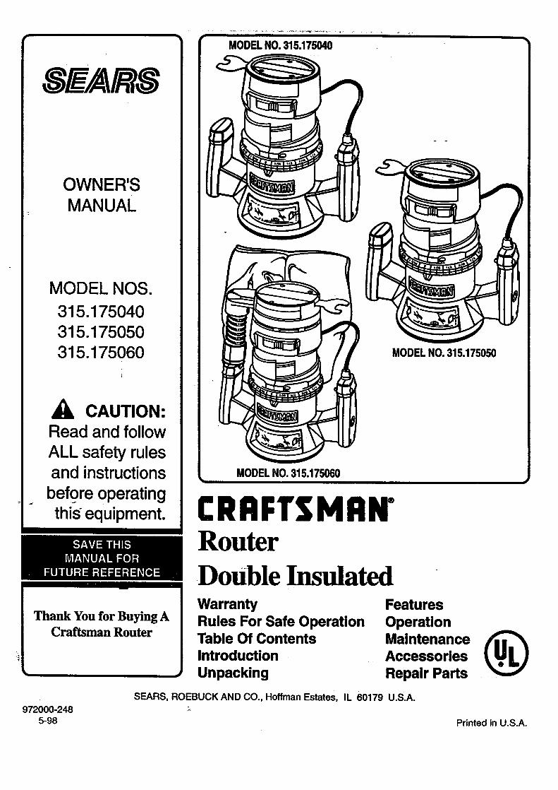
MODEL NO. 315.175040 •
, EAR
OWNER'SMANUAL
MODEL NOS.
315.175040315.175050315.175060
CAUTION:Read and follow
ALL safety rulesand instructions
. before operatingth_ °equipment.
MODELNO.315.175060
MODELNO.315.175050
CRAFTSMI:iN"Router
Thank You for Buying ACraftsman Router
DoUble InsulatedWarrantyRules For Safe OperationTable Of ContentsIntroductionUnpacking
FeaturesOperation
Maintenance (_Acce.ssoriesRepair Parts
972000-2485-98
SEARS, ROEBUCK AND CO., Hoffman Estates, IL 60179 U.S.A.
Printed in U.S.A.

i i i ii
FULL ONE YEAR WARRANTY ON CRAFTSMAN ROUTER
If this Craftsman Router fails to give complete satisfaction within one year from the date of purchase, RETURN ITTO THE NEAREST SEARS STORE IN THE UNITED STATES, and Sears will repair it, free of charge.
If this Craftsman Router is used for commercial or rental purposes, this warranty applies for only 90 days from thedate of purchase.
This warranty gives you specific legal rights, and you may also have other rightswhich vary from state to state.
Sears, Roebuck and Co., DEPT. 817 WA, Hoffman Estates, IL 60179
The purpose of safety symbols is to attract your attention to possible dangers. The safety symbols, and theirexplanations with them, deserve your careful attention and understanding. The safety warnings do not bythemselves eliminate any danger. The instructions or warnings they give are not substitutes for proper accidentprevention measures.
SYMBOL
NOTE:
MEANINGii
SAFETY ALERT SYMBOL:
Indicates caution Or warning. May be used in conjunction with other symbols or pictogrephs.ii i
WARNING: Failure to obey a safety warning can result in serious injury to yourself or to others. Alwaysfollow the safety precautions to reduce the risk of fire, electric shock and personal injury.
i ii
CAUTION: Failure to obey a safety waming may result in property damage or personal injury to yourselfor to others. Always follow the safety precautions to reduce the risk of fire, electric shock and personalinjury.
i
Advises you of information or instructions vital to the operation or maintenance of the equipment.
DOUBLE INSULATION is a safety concept inelectric powertools which eliminates the need for the usual three wire
grounded power cord and grounded supplysystem.Whereverthere iselectric current inthe tool there are two complete setsof insulation to protect the user. All exposed metal parts areisolatedfromintemal metal motorcomponentswith protectinginsulation.
IMPORTANT - Servicing of a tool with double insulationrequires extreme care and knowledge of the system andshould be performed only by a qualified service technician.For service we suggest you return the tool to your nearestSears Store for repair.Always use originalfactory replacementparts when servicing.
ELECTRICAl:.' CONNECTION
Your router has a prec,_ion built electric motor. It should be connected to a power supply that is 120 volts, 60 Hz, AC only(normal household current). Do not operate this tool on direct current (DC). A voltage drop of more'than 10 percent willcause a loss of power and the motor will overheat. If your tool does not operate when plugged into an outlet, double-checkthe power supply.
ii i
Look for this symbol to point out important safety precautions.It means attention!!! Your safety is involved.
Paoe 2

WARNING:Do not attempt to operate this tool until you haveread thoroughly and understand completely allinstructions, safety rules, etc. contained in thismanual. Failure to comply can result in accidentsinvolving fire, electric shock, or serious personalinjury. Save owner's manual and review frequentlyfor continuing safe operation, and instructing otherswho may use this tool.
WARNING:
The double insulatedsystem is intendedto protecttheuser from shock resultingfrom a break in the tool'sinternalwiring. Observeall normal safety precautionsrelatedto avoidingelectricalshock.
i
READ ALL INSTRUCTIONS
1. KNOW YOUR POWER TOOL. Read owner's
manual carefully. Learn its applications andlimitationsas well as the specificpotentialhazardsrelated to this tool.
o
.
4.
GUARD AGAINST ELECTRICAL SHOCK bypreventing body contact with grounded surfaces.For example: Pipes, radiators, ranges, refrigeratorenclosures.
KEEP GUARDS IN PLACE and in working order.
KEEP WORK AREA CLEAN. Cluttered areasand benches invite accidents.
5. AVOID DANGEROUS ENVIRONMENT. Don't
use power tool in damp or wet locations or expose
to rain. Keep work area well lit,
6. KEEP CHILDREN AND VISITORS AWAY. All
visitors should wear safety glasses and be kepta safe distance from work area. Do not letvisitors contact tool or extension cord.
7. STORE IDLE TOOLS. When not in use tools
should be stored in a dry and high or locked-upplace-, out of the reach of children.
8. DON'T FORCE TOOL. It will do the job betterand safer at the rate for which it was designed.
9. USE RIGHT TOOL. Don't force small tool or
attachment to do the job of a heavy du_ tool.Don't use =tool for purpose not intended - forexample - A cir.eularsaw should never be usedfor cutting tree limbs or 10gs.
10. WEAR PROPER APPAREL. Do not wear loose
clothing or jewelry that can get caught in tool'smoving parts and cause personal injury. Rubbergloves and non-skid footwear are recommendedwhen working outdoors. Wear protective hair
covering to contain long hair and keep it frombeing drawn into nearby air vents.
11. ALWAYS WEAR SAFETY GLASSES. Everydayeyeglasses have only impact-resistant lenses;they are NOT safety glasses.
12. PROTECT YOUR LUNGS. Wear a face or dust
mask if operation is dusty.
13. PROTECT YOUR HEARING. Wear hearingprotection duringextended periods of operation.
14. DON'T ABUSE CORD. Never carry tool by cordor yank it to disconnect from receptacle. Keepcord from heat, oil and sharp edges.
15. SECURE WORK. Use clamps or a vise to holdwork. Both hands are needed to operate the tool.
16. DON'T OVERREACH. Keep proper footing andbalance at all times. Do not use on a ladder or
unstable support.
17. MAINTAIN TOOLS WITH CARE. Keep toolssharp at all times, and clean for best and safestperformance. Follow instructions for lubricatingand changing accessories.
18. DISCONNECT TOOLS. When not in use, beforeservicing,orwhen changing attachments, blades,bits, cutters,etc., all tools shouldbe disconnectedfrom power supply.
19. REMOVE ADJUSTING KEYs AND WRENCHES.
Form habit of checking to see th8t keys andadjusting wrenches are removed from tool be-fore tuming it on.
20. AVOID ACCIDENTAL STARTING. Don't carryplugged-in tools with finger on switch. Be sureswitch is off when plugging in.
Page 3
............_-_..........._............" AFERULES_ FOR,!S OP ERATIOK(Cd_ntinu_)_
21.
22.
23.
MAKE SURE YOUR EXTENSION CORD IS IN
GOOD CONDITION. When using an extension
cord, be sure to use one heavy enough to carry thecurrent your product will draw. An undersized cord
will cause a drop in line Voltage resulting in loss ofpower and overheating. A wire gage size (A.W.G.)of at least 14 is recommended for an extension
cord I00 feet or less in length. A cord exceedingI00 feet is not recommended. If in doubt, use the
next heavier gage. The smaller the gage number,the heavier the cord.
OUTDOOR USE EXTENSION CORDS. When tool
is used outdoors, use only extension cords suitablefor use outdoors. Outdoor approved cords aremarked with the suffLxW-A, for example - SJTW-Aor SJOW-A.
KEEP CUTTERS CLEAN AND SHARP. Sharpcutters minimize stalling and kickback.
24. KEEP HANDS AWAY FROM cu'n'ING AREA.
Keep hands away from cutters. Do not reachundemeath work while cutter is rotating. Do notattempt to remove material while cutter is rotating.
25. NEVER USE IN AN EXPLOSIVE ATMOSPHERE.
Normal sparking of the motor could ignite fumes.
26. INSPECT TOOL CORDS PERIODICALLY and
if damaged, have repaired at your nearest SearsRepair Center. Stay constantly aware of cordlocation.
27. INSPECT EXTENSION CORDS PERIODI-CALLY and replace if damaged.
28. KEEP HANDLES DRY, CLEAN, AND FREEFROM OIL AND GREASE. Always use a clean
cloth when cleaning. Never use brake fluids,gasoline, petroleum-based products or any strong
solvents to clean your tool.
29. STAY ALERT. Watch what you are doing anduse common sense. Do not operate tool when
you are tired. Do not rush.
30. CHECK DAMAGED PARTS. Before further use
of the tool, a guard or other part that is damaged
should be carefully checked to determine that itwill operate properly and perform its intendedfunction. Check for alignment of moving parts,binding of moving parts, breakage of parts,mounting, and any other conditions that mayaffect its operation. A guard or other part that isdamaged should be properly repaired or replacedby an authorized service center unless indicatedelsewhere in this instructionmanual.
31. DO NOT USE TOOL IF SWITCH DOES NOTTURN IT ON AND OFF. Have defective switches
replaced by an authorized service center.
32. INSPECT FOR and remove all nails from lumber
before routing.
33. DRUGS, ALCOHOL, MEDICATION. Do not
operate tool while under the influence of drugs,alcohol, or any medication.
34. WHEN SERVICING USE ONLY IDENTICALCRAFTSMAN REPLACEMENT PARTS.
35. POLARIZED PLUGS. To reduce the risk of
• electric shock, this tool has a polarized plug (oneblade is wider than the other). This plug will fit ina polarized outlet only one way. If the plug doesnot fit fully in the outlet, reverse the plug. If it stilldoes not fit, contact a qualified electrician toinstall the proper outlet. D<_not change the plugin any way.
36. DO NOT USE TOOL UNDER "BROWN-OUT"OR OTHER LOW VOLTAGE CONDITIONS.
Also, do not use with any device that could causethe power supply voltage to change.
37. WHEN USING THIS ROUTER WITH AROUTER TABLE, HELP PREVENT POS-SIBLE SERIOUS INJURY BY KEEPING THE
CUTTER GUARDED AT ALL TIMES. Use onlyrouter tables, with guards, that have been de-signed for use on routers that are of this type,size, and weight.
38. SAVE THESE INSTRUCTIONS. Review themfrequently and use them tO instruct others whomay use this tool. If you loan s_meone this tool,loan them these instructions also.
[AwA..l.G:]_ The operation 0; any router can result in foreign objects being thrown into your eyes, which ]
E(_M-_=_)_ can result in severe eye damage. Before beginning power tool operation, always wearp_ safety goggles or safety glasses with side shields and a full face shield when needed. We
recommend Wide Vision Safety Mask for use over eyeglasses or standard safety glasses,_ with side shields, available at Sears Retail Stores.
Page 4
[] Warranty ........................ ,...., .................. 2
[] Rules For Safe Operation ........... ,.,.,.2-4[] Table •Of Contents ................................. 5
[] Introduction and Product
Specifications ....................................... 6
[] Unpacking ............................................. 7
[] Features .............................................. 7-9
Switch .................................................. 7
Lock-On Button ....................................... 7
Chip Shield ............................................. 7
Wrench Storage Area ............................. 7
Variable Speed (Model Nos,
315.175050 and 315.175060 Only) ........ 7
Dust Bag Assembly(Model No. 315.175060 Only) ................ 7
To Install Dust Bag ............................ 7To Empty Dust Bag ........................... 7
Know Your Router .................................. 8Model No. 315.175040 ...................... 8
Model No. 315.175050 ...................... 9Model No. 315.175060 ...................... 9
[] Operation ........................................ 10-17
Installing/Removing Cutters .................. 10
Depth Of Cut Adjustments .................... 11
Depth Of Cut Adjustments WhenMounted To A Router Table ................. 12
Variable Speed (Model Nos.315. 175050 and 315.175060) ............. 12Practice Before Actual Use ................... 12
Routing ................................................ 13
Freehand Routing ................................. 13
[]
[]
[]
Proper Feeding ..................................... 14
Speed Selections (Model Nos.
315.175050 and 315.175060 Only) ...... 14Rate Of Feed ........................................ 14
Force Feeding ...................................... 14
Too Slow Feeding ............ _.................... 14
Depth Of Cut ......................................... 15
Direction Of Feed and Thrust ............... 15
Routing ................................................ 15
Starting and Ending A Cut
Internal Routing ............................... 16
Edging With Pilot Bits ........................... 16
Edge Routing ........................................ 16
Routing With Guide Bushings ............... 17Router Tables ....................................... 17
Maintenance ................................... 17-22
Switch Replacement
(Model No. 315.175040) ....................... 17
Switch Replacement (Model Nos.
315.175050 and 315.175060) .............. 18
Light Bulb Replacement ....................... 19
Proper Care Of Cutters ......................... 19
Proper Care Of Collet ........................... 19Lubrication ............................................ 19
Helpful Hints ......................................... 19General ................................................ 20
Extension Cords ................................... 20
Accessories ........................................ 21
Exploded View and Parts List ...... 22-27
Parts Ordering I Service ..................... 28
Page 5
Congratulations and thank you for buying thisCraft=man router. It has been designed, engineered andmanufactured to provide you with Sears high standard ofdependability, ease of operation, and operator safety.Properly cared for, it will give you years of rugged, trouble-free performance.
Your router has many features for making routing operationsmore pleasant and enjoyable. Safety, performance anddependability have been given top pdority in the design ofthis router making it easy to maintain and operate.
CAUTION:Carefully read through this entire owner's manual beforeusing your new router. Pay close attention to the RulesFor Safe Operation, Warnings and Cautions. If you useyour router propedy and only for what it is intended, youwill enjoy years of safe, reliable service.
SPECIFICATIONS:
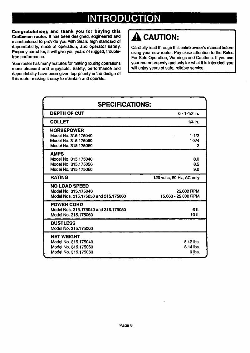
DEPTH OF CUT
COLLET
HORSEPOWERModel No. 315.175040Model No. 315.175050Model No. 315.175060
AMPSModel No. 315.175040Model No. 315.175050Model No. 315.175060
RATING
NO LOAD SPEEDModel No. 315.175040Model Nos. 315.175050 and 315.175060
POWER CORDModel Nos. 315.175040 and 315.175050Model No. 315.175060
DUSTLESSModel No. 315.175060
NET WEIGHTModel No. 315.175040Model No. 315.175050Model No. 315.175060
0 - 1-1/2 in.
1/4 in.
1-1/21-3/4
2
8.08.59.0
120 volts, 60 Hz, AC only
25,000 RPM15,000 - 25,000 RPM
6ft.10ft.
8.13 Ibs.8.14 Ibs.
9 Ibs.
Paae 6
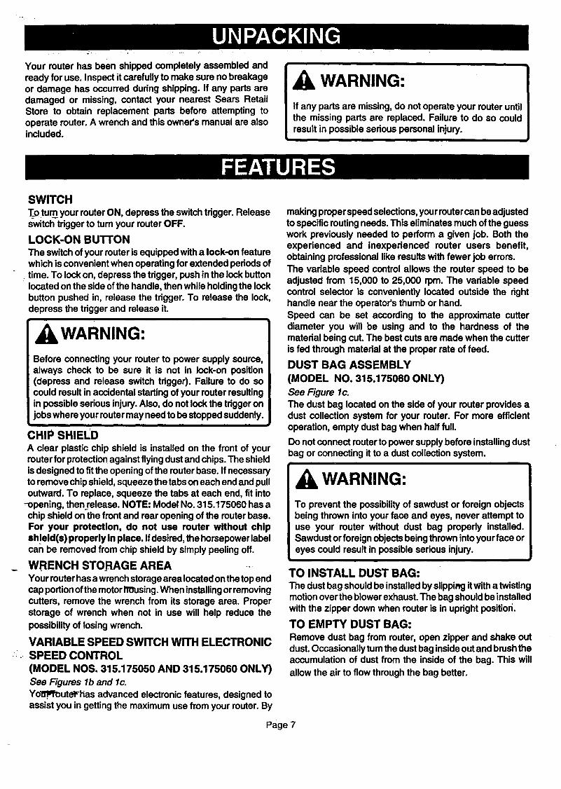
Your muter has been shipped completely assembled andready for use. Inspect it car fully to make sure no breakageor damage has occurred during shipping. If any parts aredamaged or missing, contact your nearest Sears RetailStore to obtain replacement parts before attempting tooperate router. A wrench and this owner's manual are alsoincluded.
i
WARNING:
If any parts are missing, do not operate your router untilthe missing parts are replaced. Failure to do so couldresult in possible serious personal injury.
SWITCH
T_otum your router ON, depress the switch trigger. Releaseswitch trigger to turn your router OFF.
LOCK-ON BUTTON
The switch of your router is equipped with a lock-on featurewhich is convenient when operating for extended periods of
• time. To lock on, depress the trigger, push inthe lock buttonlocated on the side of the handle, then while holdingthe lockbutton pushed in, release the trigger. To release the lock,depress the trigger and release it.
WARNING:Before connecting your router to power supply sour e,always check to be sure it is not in lock-on position(depress and release switch trigger). Failure to do socould result in accidental starting of your muter resultingin possible serious injury. Also, do not lock the trigger onjobs where your muter may need to be stopped suddenly.
i
CHIP SHIELDA clear plastic chip shield is installed on the front of yourrouter for protectionagainst flying dust and chips. The shieldisdesigned to fit the opening of the muter base. If necessaryto remove chip shield, squeeze the tabs on each end and pulloutward. To replace, squeeze the tabs at each end, fit into
-opening, thenrelease. NOTE: Model No. 315.175060 has achip shield on the front and rear opening of the router base.For your protection, do not use router without chipsh!eld(s) properly in place. Ifdesired, the horsepower labelcan be removed from chip shield by simply peeling off.
WRENCH STORAGE AREAYour router has a wrench storage area located onthe topendcap portionof the motor IlOusing.When installing orremovingcutters, remove the wrench from its storage area. Properstorage of wrench when not in use will help reduce the
possibility of losing wrench.
VARIABLE SPEED SWITCH WITH ELECTRONICSPEED CONTROL
(MODEL NOS. 315.175050 AND 315.175060 ONLY)
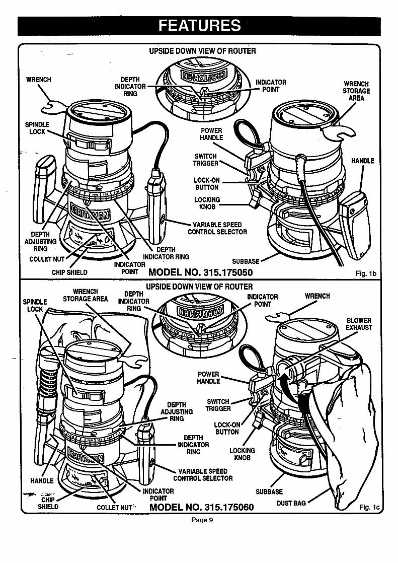
See Figures lb and lc.Yol_q_outel_as advanced electronic features, designed toassist you in getting the maximum use from your router. By
making pr perspeed selections, your muter can be adjustedto specific routing needs. This eliminates much of the guesswork previously needed to perform a given job. Both theexperienced and inexperienced router users benefit,obtaining pr fessional like results with fewer job err rs.The variable speed control allows the router speed to beadjusted from 15,000 to 25,000 rpm. The variable speedcontrol selector is conveniently located outside the righthandle near the operator's thumb or hand.Speed can be set according to the approximate cutterdiameter you will be using and to the hardness of thematerial being cut. The best cuts are made when the cutteris fed thr ugh material at the proper rate of feed.
DUST BAG ASSEMBLY
(MODEL NO. 315.175060 ONLY)
See Figure lc.The dust bag located on the side of your muter provides adust collection system for your router. For more efficientoperation, empty dust bag when half full.
Do not connect r uterto power supply before installing dustbag or connecting it to a dust collection system.
WARNING:
To prevent the possibility of sawdust or foreign objectsbeing thrwn into your face and eyes, never attempt touse your router without dust bag propedy installed.Sawdust or foreign objects being thrwn intoyour face oreyes could result in possible serious injury.
i
TO INSTALL DUST BAG:The dust bag should be installed by slippi_j it v_th a twistingmotion over the blower exhaust. The bag should be installedwith the zipper down when router is in upright positiori.
TO EMPTY DUST BAG:Remove dust bag from router, open zipper and shake outdust. Occasionally turn the dust bag inside outand brash theaccumulation of dust from the inside of the bag. This will
allow the air to flow thr ugh the bag better.
Page 7
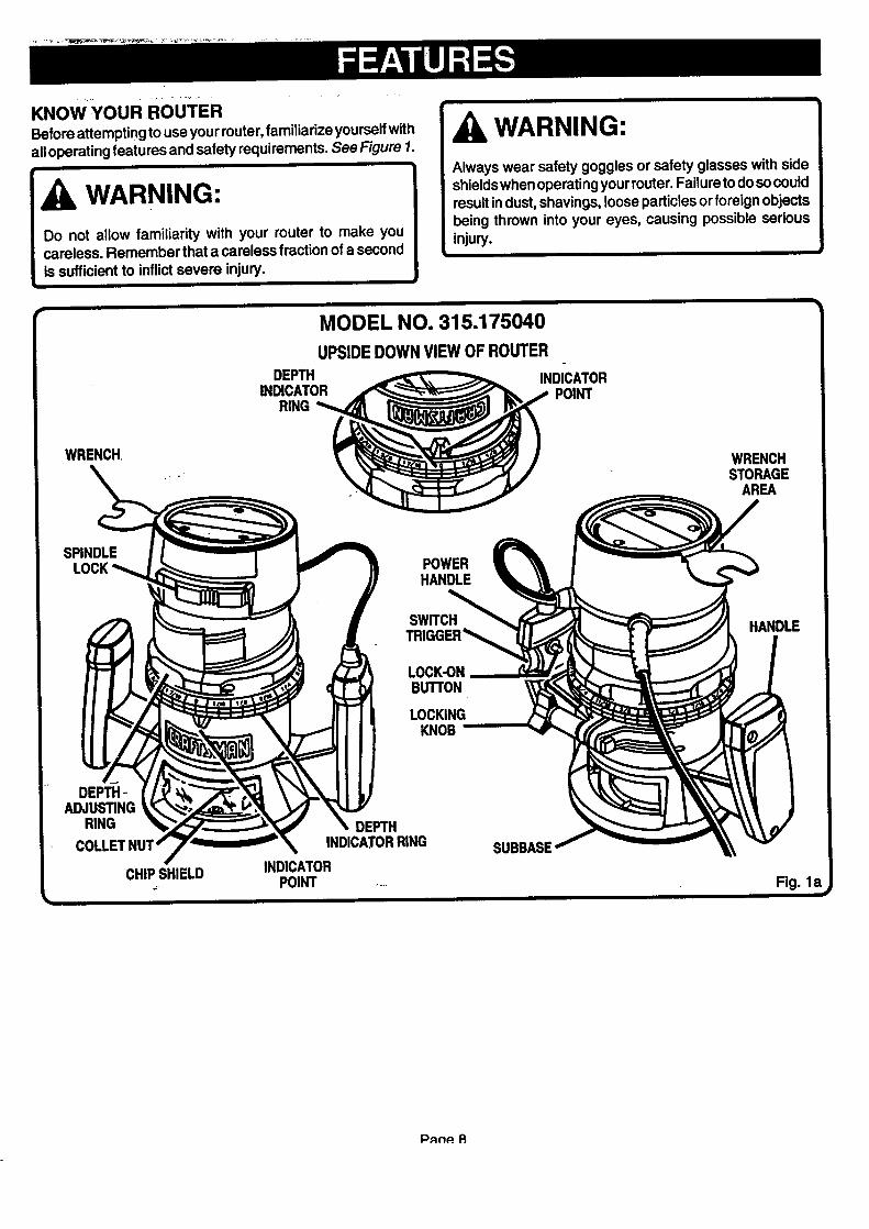
KNowYouR RoU_FER
Before attempting to use your router, familiarize yourself withall operating features and safety requirements. See Figure 1.
i
WARNING:
Do not allow familiarity with your router to make youcareless. Remember that a careless fraction of a secondis sufficient to inflict severe injury.
WARNING:
Always wear safety goggles or safety glasses with sideshieldswhen operating your router. Failure to doso couldresult indust, shavings, loose particles or foreign objectsbeing thrown into your eyes, causing possible seriousinjury.
WRENCH,
SPINDLE
DEPTH-ADJUS_NG
RING
CHIPSHIELD..:,.
MODEL NO. 315.175040UPSIDE DOWN VIEW OF ROUTER
DEPTH INDICATORINDICATOR POINT
RING
POWERHANDLE
SWITCH
LOCK-ONBURTON
LOCKINGKNOB
DEPTHINDICATORRING
INDICATORPOINT ....
SUBBASE
WRENCHSTORAGE
AREA
HANDLE
Fig. la
Pnn_ R
• UPSIDE DOWNVIEW OF ROUTER 7
WRENCH DEPTH
RING
INDICATORPOINT
WRENCHSTORAGE
AREA
SPINDLE
DEPTHADJUSTING.
RING
CHIPSHIELD
WRENCH
SPINDLE STORAGEAREA
HANDLE
CHllSHIELD
POWERHANDLE
SWITCH
LOCK_NBUTTON
LOCKINGKNOB
VARIABLESPEEDCONTROLSELECTOR
DEPTHINDICATORRING
INDICATOR SUBBASE
POINTMODEL NO. 315.175050
UPSIDE DOWN VIEW OF ROUTERDEPTH
INDICATORRING
POWER
COLLETNUT'_'
DEPTH SWITCH,ADJUSTING TRIGGER
RING
DEPTHINDICATOR
RING
BUTTON
LOCKINGKNOB
VARIABLESPEEDCONTROLSELECTOR
INDICATORPOINT
MODEL NO. 315.175060
Page 9
INDICATORPOINT
WRENCH
SUBBASE
DUSTBAG
HANDLE
Fig. lb
BLOWEREXHAUST
Fig. lc
L
i
WARNING:•SPINDLE A_' _ _ )i
Your router should never be connected to power supply LOCK _ /7 _ I _ [J[
when you are assembling XI _ _ _ _,___L__ 1install ng or removing cul
°.oncn0,ourou.rthat o ,uld cause serious in]
:ee Fi_ Jres 2 and 3.
TO LOCK P H INTO TO UNLOCKSPINDLE LOCKANDUNLOCK SPINDLE Fig. 2
when you are assembling parts, making adjustments,installing or removing cutters, or when not in use.Disconnecting your routerwill prevent accidental startingthat could cause serious injury.
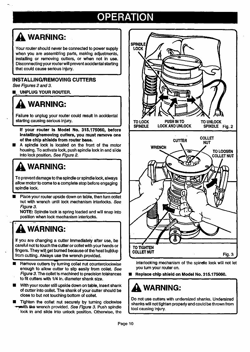
INSTALLING/REMOVING CUTTERSSee Figures 2 and 3.
II UNPLUG YOUR ROUTER.
Failure to unplug your router could result in accidentalstarting causing serious injury.
If your• router is Model No. 315.175060, beforeinstalling/removing cutters, you must remove oneof the chip shields from router base.
• A spindle lock is located on the front of the motorhousing. To activate lock, push spindle lock in and slideinto lock position. See Figure 2.
WARNING:I To prevent damage to the spindle or spindle lock, alwaysI allow motor to come to a complete stop before engaging
L spindle lock.
• Place your router upside down on table, then turn colletnut with wrench until lock mechanism interlocks. SeeFigure 3.NOTE: Spindle lock is spring loaded and will snap intoposition when lock mechanism interlocks.
WARNING:-
If you are changing a cutter immediately after use, becareful notto touch the cutter or collet with your hands orfingers. They willget bumed because of the heat bu.j!dupfrom cutting. Always use the wrench provided.
I
• Remove cutters by'_uming collet nut counterclockwiseenough to allow cutter to slip easily from collet. SeeFigure 3. The collet is machined to precision tolerancesto fit cutters with 114in. diameter shank size.
• " COLLETCUTTER NUT
",
" " !
TO TIGHTEN
COLLETNUT Fig. 3 •ik,,,,
interlocking mechanism of the spindle lock will not letyou turn your router on.
• Replace chip shield on Model No. 315.175060.i
• With your muter still upside down on table, insert shankof cutter into collet. The shank of your Cutter should beclose to but not touching bottom of collet.
• Tighten the collet nut securely by turning clockwise.,._with_be wrench provided. See Figure 3. Push spindle
lock in and slide into unlock position. Otherwise, the
WARNING:
Do not use cutters with undersized shanks. Undersizedshanks will nottighten properly and could be thrown fromtool causing injury.
i
Page 10
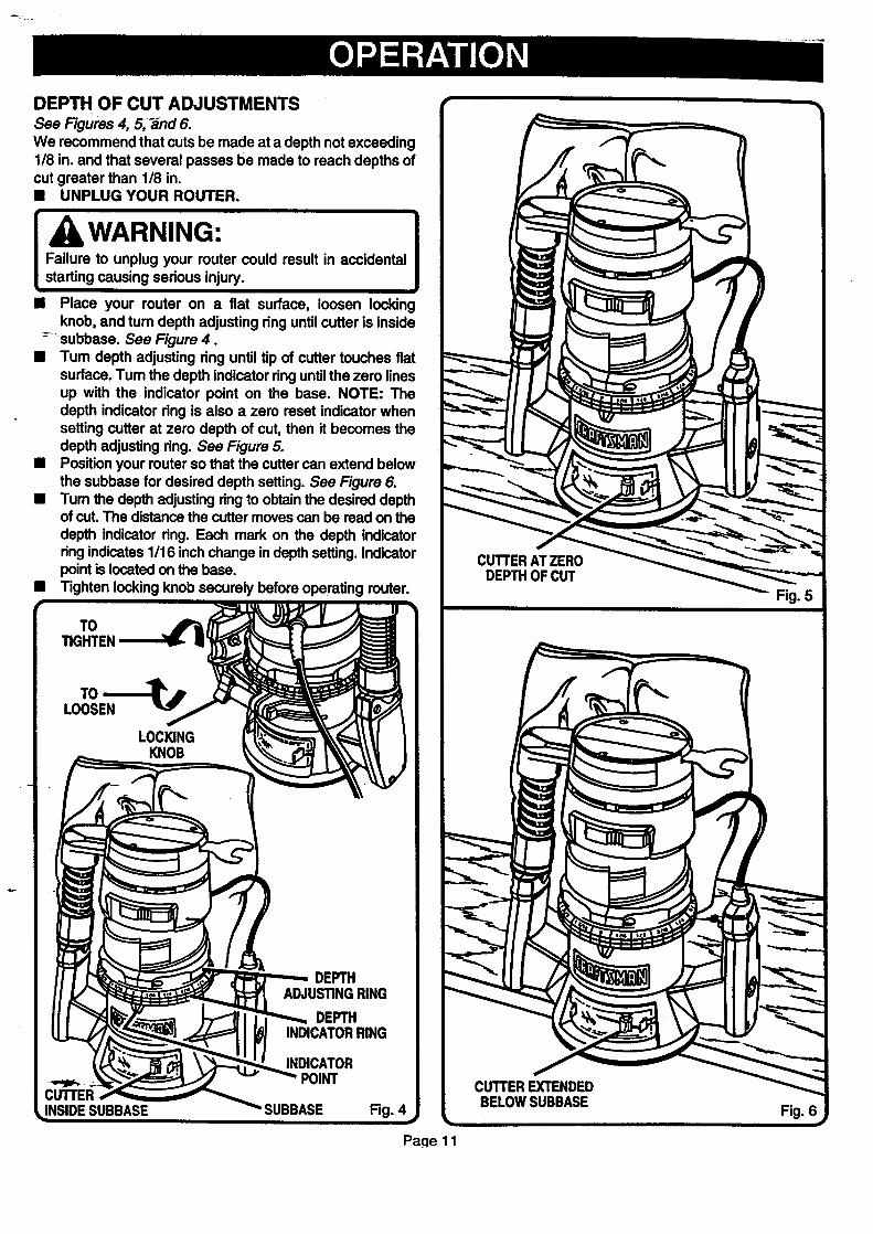
DEPTH OF CUT ADJUSTMENTS
See Figures 4, 5, _nd 6.We recommend that cuts be made at a depth not exceeding118in. and that several passes be made to reach depths ofcut greater than 118 in.
[u uooou !Failure to unplug your router could result in accidentalstarting causing serious injury.
• Place your router on a fiat surface, loosen lockingknob, and tum depth adjusting ring untilcutter is inside
-- _subbase. See Figure 4.•Tum depth adjusting ring until tip of cutter touches fiat
surface. Tum the depth indicator ring until the zero linesup with the indicator point on the base. NOTE: Thedepth indicator dng is also a zero reset indicator whensetting cutter at zero depth of cut, then it becomes thedepth adjusting ring. See Figure 5.
• Position your router so that the cutter can extend belowthe subbase for desired depth setting. See Figure 6.
• Tum the depth adjusting ring to obtain the desired depthof cut. The distance the cutter moves can be read on thedepth indicator ring. Each mark on the depth indicatorring indicates 1116inch change in depth setting. Indicatorpoint is located on the base.
• Tighten locking knob securely before operating router.
Fig. 4
cUTrER ATZERODEPTHOF CUT
Fig. 5
Pa_e 11
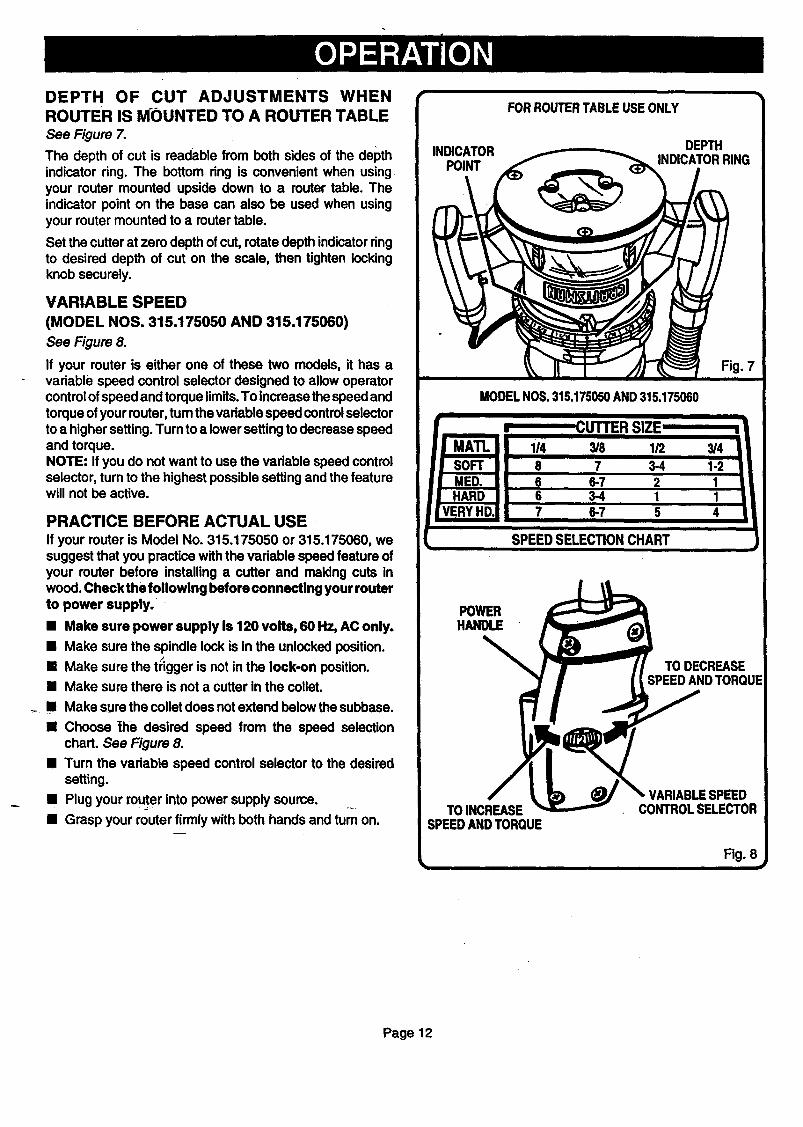
DEPTH OF CUT ADJUSTMENTS WHEN
ROUTER IS MOUNTED TO A ROUTER TABLE
See Figure 7.
The depth of cut is readable from both sides of the depthindicator ring. The bottom ring is convenient when usingyour router mounted upside down to a router table. Theindicator point on the base can also be used when usingyour router mounted to a router table.
Set the cutter at zero depth of cut, rotate depth indicator ringto desired depth of cut on the scale, then tighten lockingknob securely.
VARIABLE SPEED
(MODEL NOS. 315.175050 AND 315.175060)
See Figure 8.
If your router is either one of these two models, it has avariable speed control selector designed to allow operatorcontrol of speed and torque limits.To increase the speed andtorque of your router, tum the variable speed controlselectorto a higher setting. Turn to a lower setting to decrease speedand torque.NOTE: If you do not want to use the variable speed controlselector, turn to the highest possible setting and the featurewill not be active.
PRACTICE BEFORE ACTUAL USEIf your router is Model No. 315.175050 or 315.175060, wesuggest that you practice with the vadable speed feature ofyour router before installing a cutter and making cuts inwood. Check the following before connecting your routerto power supply.
• Make sure power supply is 120 volts, 60 Hz, AC only.
• Make sure the spindle lock is in the unlocked position./
• Make sure the _gger is not in the lock-on position.
• Make sure there is not a cutter in the collet.
• Make sure the collet does not extend below the subbase.
• Choose the desired speed from the speed selectionchart. See Figure 8.
• Turn the variable speed control selector to the desiredsetting.
• Plug your muter into power supply source. ..
• Grasp your router firmly with both hands and turn on.
MODELNOS.315.175050AND315.175060
CUTTER SIZE'
SPEEDSELECTIONCHART
POWERHANDLE
TO DECREASESPEEDANDTORQUE
/TO INCREASE
SPEEDANDTORQUE
VARIABLESPEEDCONTROLSELECTOR
Fig. 8
Page12
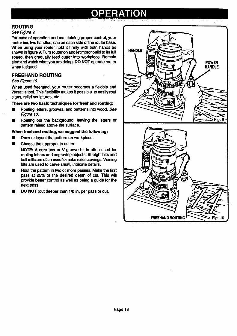
ROUTING .......
See Figure 9. ----
For ease of operation and maintaining proper control, yourrouter has two handles, one on each side of the router base.When using your router hold it firmly with both hands asshown in figure 9. Tum router on and let motor build to its fullspeed, then gradually feed cutter into workpiece. Remainalert and watch what you are doing. DO NOT operate routerwhen fatigued.
FREEHAND ROUTINGSee Figure 10.
When used freehand, your router becomes a flexible andV-ersatlletool. This flexibility makes it possible to easily routsigns, relief sculptures, etc.
There are two basic techniques for freehand routing:.
• Routing letters, grooves, and pattems into wood. SeeFigure 10.
• Routing out the background, leaving the letters orpattem raised above the surface.
When freehand routing, we suggest the following:
• Draw or layout the pattem on workpiece.
• Choose the appropriate cutter.
NOTE: A core box or V-groove bit is often used forroutingletters and engraving objects. Straight bits andball millsare often used to make relief carvings. Veiningbits are used to carve small, intricate details.
• Rout the pattem in two or more passes. Make the firstpass at 25% of the desired depth of cut. This willprovide better control as well as being a guide for thenext pass.
• DO NOT rout deeper than 1/8 in. per pass or cut.
POWERHANDLE
Fig. 9
Page 13
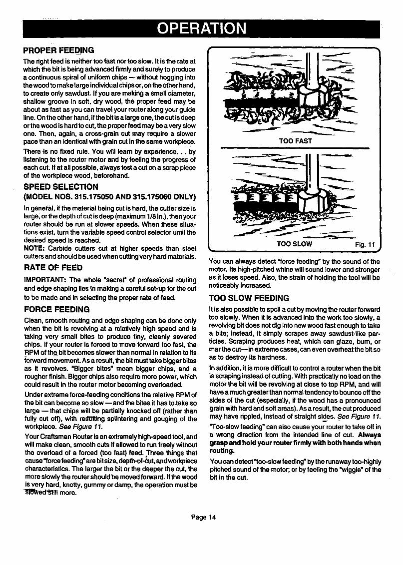
PROPER FEED.ING
The right feed is neither too fast nor too slow. It is the rate atwhich the bit is being advanced firmly and surely to producea continuous spiral of uniform chips --without hogging intothe wood to make large individualchips or, onthe other hand,to create only sawdust. If you are making a small diameter,shallow groove in soft, dry wood, the proper feed may beabout as fast as you can travel your router along your guideline. On the other hand, ifthe bit is a large one, the cut isdeeporthe wood is hard to cut, the proper feed may be a very slowone. Then, again, a cross-grain cut may require a slowerpace than an identical with grain cut in the same workpiece.
There-is no fixed rule. You will learn by experience.., bylistening to the router motor and by feeling the progress ofeach cut. If at all possible, always test a cut on a scrap pieceof the workpiece wood, beforehand.
SPEED SELECTION
(MODEL NOS. 315.175050 AND 315.175060 ONLY)
In general, if the material being cut is hard, the cutter size islargel orthe depth of cut is deep (maximum 118in.), then yourrouter should be run at slower speeds. When these situa-tions exist, turn the variable speed control selector until thedesired speed is reached.NOTE: Carbide cutters cut at higher speeds than steelcutters and should be used when cuttingvery hard materials.
RATE OF FEED
IMPORTANT: The whole "secret" of professional routingand edge shaping lies in making a careful set-up for the cutto be made and in selecting the proper rate of feed.
FORCE FEEDING
Clean, smooth routing and edge shaping can be done onlywhen the bit is revolving at a relatively high speed and istaking very small bites to produce tiny, cleanly severedchips. If your router is forced to move forward too fast, theRPM of the__bit becomes slower than normal in relation to itsforward movement. As a result, the bitmust take bigger bitesas it revolves. =Bigger bites" mean bigger chips, and arougher finish. Bigger chips also require more power, whichcould result in the router motor becoming overloaded.
Under extreme force-feeding conditions the relative RPM ofthe bit can become so slow --and the bites it has to-take solarge -- that chips will be partially knocked off (rather thanfully cut off), with redOIting splintering and gouging of theworkpiece. See Figure 11.
Your Craftsman Router is an extremely high-speed tool, andwill make clean, smooth cuts if allowed to run freely withoutthe overload of a forced (too fast) feed. Three things thatcause =force feeding" are bitsize, depth-of_ut, and workpiececharacteristics. The larger the bit or the deeper the cut, themore slowly the router should be moved forward. If the woodis very hard, knotty, gummy or damp, the operation must be
"_q!_ed:b-'tillmore.
TOO FAST
TOO SLOW Fig. 11
You can always detect "rome feeding" by the sound of themotor. Its high-pitched whine will sound lower and strongeras it loses speed. Also, the strain of holding the tool will benoticeably increased.
TOO SLOW FEEDING
It is also possible to spoil a cut by moving the router forwardtoo slowly. When it is advanced into the work too slowly, arevolving bit does not dig intonew wood fast enough to takea bite; instead, it simply scrapes away sawdust-like par-ticles. Scraping produces heat, which can glaze, bum, ormar the cut--in extreme cases, can even overheat the bit soas to destroy its hardness.
In addition, it is more difficultto control a router when the bit
is scraping instead of cutting. With practically no load on themotor the bit will be revolving at close to top RPM, and willhave a much greater than normal tendency to bounce offthesides of the cut (especially, if the wood has a pronouncedgrain with hard and soft areas). As a result, the cut producedmay have dppled, instead of straight sides. S_eeFigure 11.
='l'oo-slow feeding" can also cause your router to take off ina wrong direction from the intended line of cut. Alwaysgrasp and hold your router firmly with both hands whenrouUng.
You can detect'too-slow feeding" by the runaway too-highlypitched sound of the motor; or by feeling the "wiggle" of thebit in the cut.
Page 14
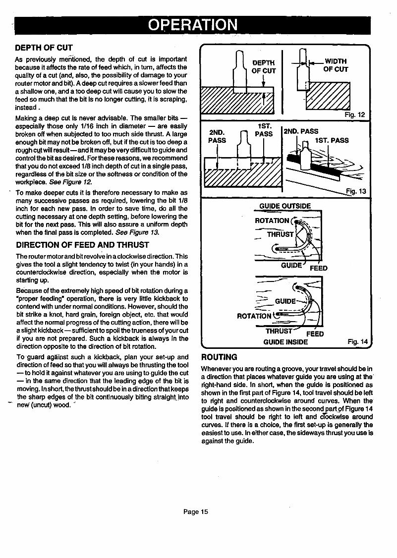
DEPTH OF CUT
As previously mentioned, the depth of cut is importantbecause it affects the rate of feed which, in turn, affects thequality of a cut (and, also, the possibility of damage to yourrouter motor and bit). A deep cut requires a slower feed thana shallow one, and a too deep cut will cause you to slow thefeed so much that the bit is no longer cutting, it is scraping,instead.
Making a deep cut is never advisable. The smaller bitsespecially those only 1/16 inch in diameter -- are easilybroken off when subjected to too much side thrust. A largeenough bit may not be broken off, but if the cut is too deep aroughcut will resultE and it may be very difficultto guide andcontrol the bitas desired. For these reasons, we recommendthat you do not exceed 1/8 inch depth of cut ina single pass,regardless of the bit size or the softness or condition of theworkpiece. See Figure 12.
To make deeper cuts it is therefore necessary to make asmany successive passes as required, lowering the bit 1/8inch for each new pass. In order to save time, do all thecutting necessary at one depth setting, before lowering thebit for the next pass. This will also assure a uniform depthwhen the final pass is completed. See Figure 13.
DIRECTION OF FEED AND THRUST
The router motorand bit revolve ina clockwise direction. This
gives the tool a slight tendency to twist (in your hands) in acounterclockwise direction, especially when the motor isstarting up.
Because of the extremely high speed of bit rotation during a"proper feeding" operation, there is very little kickback tocontend with under normal conditions. However, should thebit strike a knot, hard grain, foreign object, etc. that wouldaffect the normal progress of the cutting action, there will bea slight kickback-- sufficientto spoil the trueness of your cutif you are not prepared. Such a kickback is always in thedirection opposite to the direction of bit rotation.
Toguard ag._itlst such a kickback, plan your set-up anddirection of feed so that you will always be thrusting the tool
to hold it against whatever you are using to guide the cutm in the same direction that the leading edge of the bit ismoving. Inshod, the thrust should be ina directionthat keepsthe sharp edges of the bit continuously biting straight intonew (uncut) wood. _
2ND.PASS
1ST.PASS 2ND. PASS
1-_i"1 1ST. PASS
__._Rg. 13
GUIDE OUTSIDE
ROTATI_..,.__ON _"_1_,i_
J_-I line • i""''" FEED
__ GUID
THRUST'_ FE'ED
GUIDE INSIDE Fig. 14
ROUTING
Whenever you are routinga groove, your travel should be ina direction that places whatever guide you are using at theright-hand side. In shod, when the guide is positioned asshown in the first part of Figure 14, tool travel should be leftto dght and counterclockwise around curves. When the
guide is positioned as shown in the secondpart of Figure 14tool travel should be right to left and clockwise aroundcurves. If there is a choice, the first set-up is generally theeasiest to use. In either case, the sideways thrust you use isagainst the guide.
Page15
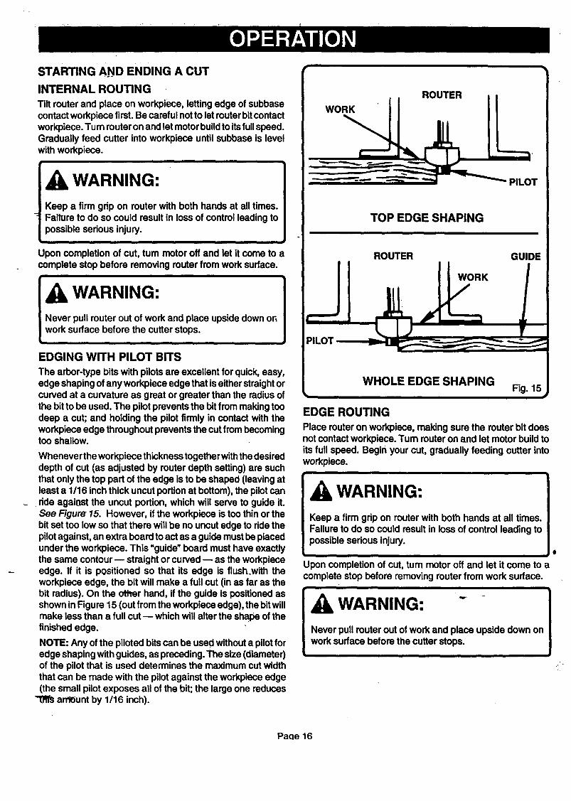
STARTING AND ENDING A CUT
INTERNALROUTING
Tilt router and place on workpiece, letting edge of subbasecontact workpiece first. Be careful not to let router bitcontactworkpiece. Turn router on and let motor buildto itsfullspeed.Gradually feed cutter into workpiece until subbase is levelwith workpiece.
WARNING:Keep a firm grip on router with both hands at all times.Failure to do so could result in loss of control leading topossible serious injury.
i i
Upon completion of cut, turn motor off and let it come to acomplete stop before removing router from work surface.
WARNING:
Never pull router out of work and place upside down onwork surface before the cutter stops.
i
EDGING WITH PILOT BITS
The arbor-type bits with pilots are excellent for quick, easy,edge shaping of any workpiece edge that iseither straight orcurved at a curvature as great or greater than the radius ofthe bit to be used. The pilot prevents the bit from making toodeep a cut; and holding the pilot firmly in contact with theworkpiece edge throughout prevents the cut from becomingtoo shallow.
Whenever the workpiece thickness together withthe desireddepth of cut (as adjusted by router depth setting) are suchthat only the top part of the edge is to be shaped (leaving atleast a 1/16 inch thick uncut portion at bottom), the pilotcanride against the uncut portion, which will serve to guide it.See Figure 15. However, if the workpiece is too thin or thebit set too low so that there will be no uncut edge to ride thepilotagainst, an extra board to act as a guide must be placedunder the workpiece. This =guide" board must have exactlythe same contour -- straight or curved -- as the workpieceedge. If it is positioned so that its edge is flush.with theworkpiece edge, the bit will make a full cut (in as far as thebit radius). On the other hand, if the guide is positioned asshown in Figure 15 (outfrom the workpiece edge), the bitwillmake less than a full cut -- which will alter the shape of thefinished edge.
NOTE: Any of the piloted bits can be used without a pilot foredge shaping with guides, as preceding. The size (diameter)of the pilot that is used determines the maximum cut widththat can be made with the pilot against the workpiece edge(the small pilot exposes all of the bit; the large one reduces
arff_unt by 1/16 inch).
ROUTER
Ii_ , "----_.
TOPEDGESHAPING
ROUTER GUIDEI
WORK
PILOT
WHOLE EDGE SHAPINGFig. 15
EDGE ROUTING
Place router on workpiece, making sure the router bit doesnot contact workpiece. Tum router on and let motor build toits full speed. Begin your cut, gradually feeding cutter intoworkpiece.
WARNING:
Keep a firm grip on router with both hands at all times.Failure to do so could result in loss of control leading topossible serious injury.
Upon completion of cut, tum motor off and let it come to acomplete stop before removing router from work surface.
WARNING: -
Never pull router out of work and place upside down onwork surface before the cutter stops.
Pacle 16
ROUTING WITH GUIDE BUSHINGS
When using the Template Guide Bushings Item No. 9-25082with your router, you must visually center the bit with thebushing before beginning your cut. Your routersubbase maybe adjusted by loosening the screws holding the subbase toyour router. Be sure clamping lever is locked before center-ing bit in bushing. After centering bit with bushing, tightenscrews firmly.
WARNING:Failure to center bit with bushing or to firmly tighten
--screwsafter centering couldcause bit to come in contactwith bushing resulting in serious injury.
k
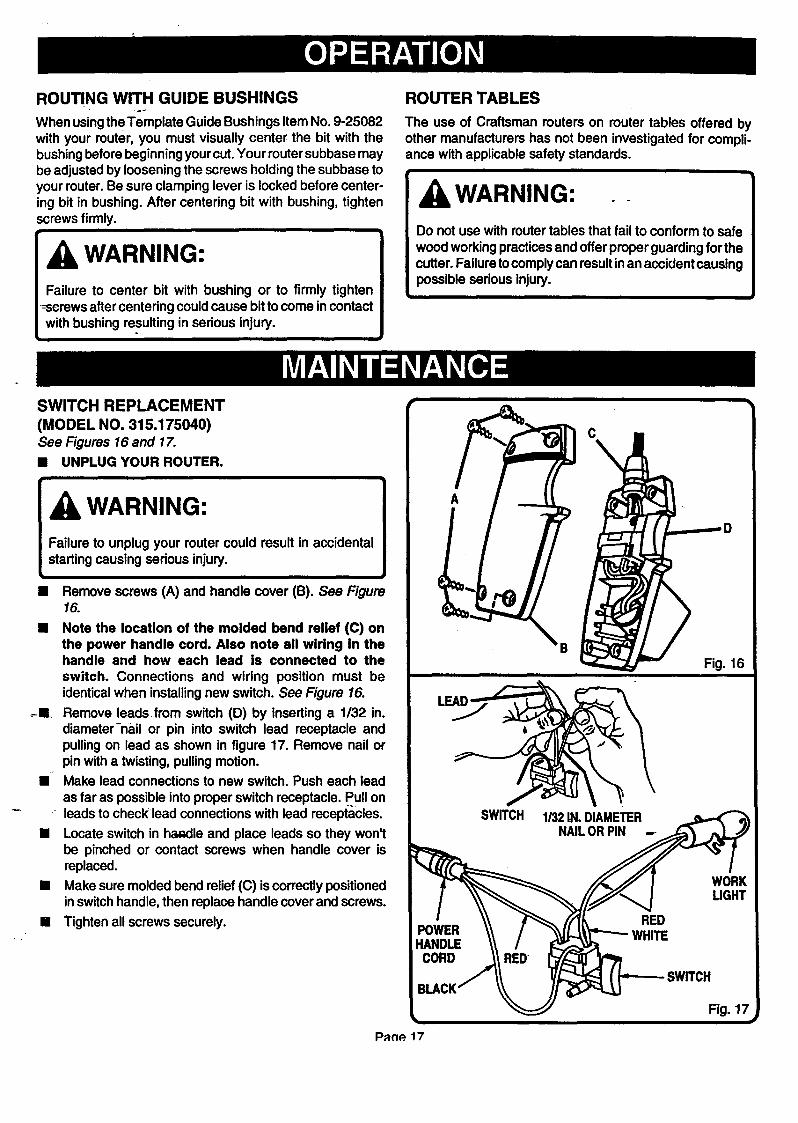
SWITCH REPLACEMENT
ROUTER TABLES
The use of Craftsman routers on router tables offered byother manufacturers has not been investigated for compli-ance with applicable safety standards.
WARNING:Do not use with router tables that fail to conform to safe
wood working practices and offer proper guarding for thecutter. Failure tocomply can result in an accident causingpossible serious injury.
(MODEL NO. 315.175040)See Figures 16and 17.
[] UNPLUG YOUR ROUTER.
i
[]
WARNING'.
Failure to unplug your router could result in accidentalstarting causing serious injury.
Remove screws (A) and handle cover (B). See Figure16.
[] Note the location of the molded bend relief (C) onthe power handle cord. Also note all wiring in thehandle and how each lead is connected to the
switch. Connections and wiring position must beidentical when installing new switch. See Figure 16.
-m Remove leads from switch (D) by inserting a 1/32 in.diameter-nail or pin into switch lead receptacle andpulling on lead as shown in figure 17. Remove nail orpin with a twisting, pulling motion.
[]_ Make lead connections to new switch. Push each lead
as far as possible into proper switch receptacle. Pull onleads to check lead connections with lead receptacles.
[] Locate switch in ha,_lle and place leads so they won'tbe pinched or contact screws when handle cover isreplaced.
[] Make sure molded bend relief ((3) iscorrectly positionedin switch handle, then replace handle cover and screws.
[] Tighten all screws securely.
A
C
SWITCH 1/32 IN. DIAMETERNAIL OR PIN
Fig. 16
P_n_ 17

SWITCH REPJ.ACEMENT (CONTINUED)(MODEL NOS. 315.175050 AND 315.175060)See Figures 18 and 19.
[] UNPLUG YOUR ROUTER.ii
WARNING:| Failure to unplug your router could result in accidental
L start.ingcausing serious injury.i i
[] Remove screws (A) and handle cover (B). See Figure
[] Note the location of the molded bend relief (C) onthe power handle cord. Also note all wiring in thehandle and how each lead is connected to the
switch, Connections and wiring position must beidentical when installing new switch. See Figure 18.
[] Remove leads from switch (D) by inserting a 1/32 in.diameter nail or pin into switch lead receptacle andpulling on lead as shown in figure 19, Remove nail orpin with a twisting, pulling motion.
• Make lead connections to new switch. Push each lead
as far as possible into proper switch receptacle. Pull onleads to check lead connections with lead receptacles.
[] Locate switch in handle and place leads so they won'tbe pinched or contact screws when handle cover isreplaced.
[] Make sure molded bend relief (C) is correctly positionedin switch handle, then replace handle cover and screws.
[] Tighten all screws securely.
VIOLET
C
VARIABLESPEED "SWITCH
Fig. 18
1/32 IN. DIAMETERNAILOR PIN
Pa(]e 18
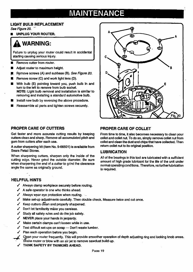
LIGHT BULB REPLACEMENT
See Figure 20. ""
• UNPLUGYOUR ROUTER.
WARNING:
Failure to unplug your router could result in accidentalstarting causing serious injury.
• Remove cutter from router.
• Adjust router to maximum height.
n Remove screws (A) and subbase (B). See Figure 20.
• Remove screw (C) and work light lens (D).
• With bulb (E) pointing toward you, push bulb in andtum to the left to remove from bulb socket.
NOTE: Light bulb removal and installation is similar toremoving and installing a standard automotive bulb.
• Install new bulb by reversing the above procedure.
• Reassemble all parts and tighten screws securely.
B
E
PROPER CARE OF CUTTERS
Get faster and more accurate cutting results by keepingcutters clean and sharp. Remove all accumulated pitch andgum from cutters after each use.
A cutter sharpening kit (Item No. 9-66501) is available fromSears Retail Stores.
When sharpening cutters, sharpen only the inside of thecutting edge. Never grind the outside diameter. Be surewhen sharpening the end of a cutter to grind the clearanceangle the same as originally ground.
HELPFUL HINTS
J
J
,/
,/
,/
,/
,/
,/
,/
,/
J
J
PROPER CARE OF COLLET
From time to time, it also becomes necessary to clean yourcollet and collet nut. To do so, simply remove collet nut fromcollet and clean the dust and chips that have collected. Thenretum collet nut to its odginal position.
LUBRICATION
All of the bearings in this tool are lubricated with a sufficientamount of high grade lubricant for the life of the unit undernormaloperating conditions. Therefore, nofurther lubricationis required.
Always clamp workpiece securely before routing.
A safe operator is one who thinks ahead.
Always wear eye protection when routing..-
Make set-up adjustments carefully. Then double check. Measure twice and cut once.
Keep cutters c'l'_anand properly sharpened.
Don't let familiarity ma.ke you careless.
Study all safety rules and do the job safely.
NEVER place your hands in jeopardy.
Make certain clamps can't loosen while in use.
Test difficult set-ups on scrap m Don't waste lumber.
Plan each operation before you begin.
Clean your router frequently. This will provide smoother operation of depth adjusting ring and locking knob areas.Shake router or blow with an air jet to remove sawdust build-up.THINK SAFETY BY THINKING AHEAD.
Paoe 19
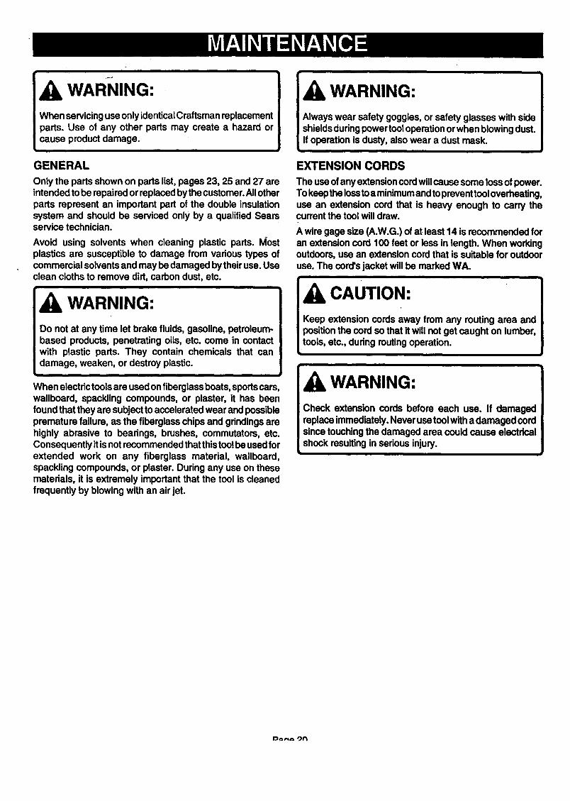
WARNING:When servicing use only identical Craftsman replacementparts. Use of any other parts may create a hazard orcause product damage.
i
GENERAL
Only the parts shown on parts list, pages 23, 25 and 27 areintended to be repaired or replaced bythe customer. All otherparts represent an important part of the double insulationsystem and should be serviced only by a qualified Searsservice technician.
Avoid using solvents when cleaning plastic pads. I_ostplastics are susceptible to damage from various types ofcommercial solvents and may be damaged by their use. Useclean cloths to remove dirt, carbon dust, etc.
WARNING:Do not at any time let brake fluids, gasoline, petroleum-based products, penetrating oils, etc. come in contactwith plastic parts. They contain chemicals that candamage, weaken, or destroy plastic.
I •
When electric tools are used on fiberglass boats, sports cars,wallboard, spackling compounds, or plaster, it has beenfound that they are subject to accelerated wear and possiblepremature failure, as the fiberglass chips and grindings arehighly abrasive to bearings, brushes, commutators, etc.Consequently it isnot recommended that thistool be used forextended work on any fiberglass material, wallboard,spackling compounds, or plaster. During any use on thesematerials, it is extremely important that the tool is cleanedfrequently by blowing with an air jet.
WARNING:
Always wear safety goggles, or safety glasses with sideshields during power tool operation or when blowing dust.If operation is dusty, also wear a dust mask.
i
EXTENSION CORDS
The usa of any extension cord willcause some loss of power.To keep the lossto a minimumandto prevent tool overheating,use an extension cord that is heavy enough to carry thecurrent the tool will draw.
A wire gage size (A.W.G.) of at least 14 is recommended foran extension cord 100 feet or less in length. When workingoutdoors, use an extension cord that is suitable for outdooruse. The cord's jacket will be marked WA.
i
CAUTION:Keep extension cords away from any routing area andposition the cord so that it will not get caught on lumber,tools, etc., dudng routing operation.
i
WARNING:
Check extension cords before each use. If damagedreplace immediately. Never use tool with a damaged cordsince touching the damaged area could cause electricalshock resulting in serious injury.
i
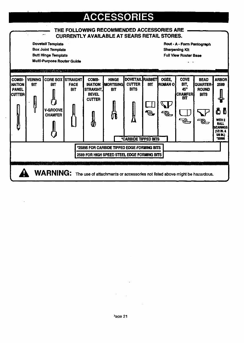
THE FOLLOWING RECOMMENDED ACCESSORIES ARECURRENTLY AVAILABLE AT SEARS RETAIL STORES.
Dovetail Template
Box Joint Template
Butt Hinge Template
Multi-Purpose Router Guide
Rout - A - Form Pantograph
Sharpening Kit
Full View Router Base
COMBI-NATIONPANEL
CUTTER
]!]] _ I II IIII III]111111I '1 IIII IIIInnl'llII
VEINING STRAIGHT COMB- HINGE DOVETAILBIT FACE INATION MORTISING CUTTER
BIT STRAIGHT, BIT BITSBEVEL
CUTLER
COREBOX RABBET OGEE,BIT BIT ROMAN0
V-GROOVE
BALLBEARINGS(_2w.amw.)
I *CARBIDETIPPEDBITSI
' 2589 FORHIGHSPEEDSTEELEDGEFORMINGBITS
rlnr' InlllllJlI flrlllllll'i II IIIIII I I I ! I II I IIIIIll'Jllll iHll ill IHIIII
WARNING: The use of attachments or accessories not listed above might be hazardous.
COVE BEAD ARBORBIT, QUARTER. 2589
45° ROUND !CHAMFER BITS
BIT c
)aqe 21
10
I SEE NOTE "A"3-----e
4
4
25
21I 23 22 ./
12 13 14" -1s
18/
17
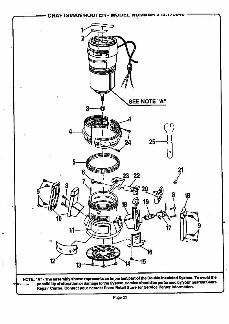
NOTE: "A" - The assembly shown represents an Important part of the Double Insulated System. To avoid thepossibility of alteration or damage to the System, service should be performed by your nearest SearsRepair Center. Contact your nearest Sears Retail Store for Service Center Information.
Page 22

CRAFTSMAN ROUTER- MODEL NUMBER 315.175040
The model number will be found on a plate attached to the motor housing. Always mention the model number Iin all correspondence regarding your ROUTER or when ordedng repair parts.]
SEE BACK PAGE FOR PARTS ORDERING INSTRUCTIONS
Key PartNo. Number
1 973741-001
2 970692-001
3 989985-003
4 974722-000
5 974131-001
6 623166-006
7 622832-014
8 606066-004
9 617966-030
10 970697-000
11 973735-002
12 606688-002
13 998586-001
14 612191-004
15 989684-001
16 975O41-001
17 610930-002
18 970696-000
19 610951-001
20 998895-001
- 21 623173-006
22 999603-001
23 931744-059
24 970855-001
25 989935-006
972000-248
PARTS LIST
Description Ouan.
Data Plate ............................................................................................. 1
Label ...................................................................................................... 1
Collet Nut (1/4 in.) .................................................................................
Depth Adjusting Ring Assembly (Includes Key No. 24) ......................... 1
Depth Indicator Ring ............................................................................. 1
* Square Head Bolt (#1/4-20 x 1-1/4 in.)..._. ............................................ 1
Roll Pin ................................................................................................... 1
* Screw (#10-32 x 3/4 in. Pan Hd.) .......................................................... 4
* Screw (#8-10 x 5/8 in. Pan Hd.) ............................................................ 8
Handle Assembly .................................................................................. 1
Base ....................................................................................................... 1
Chip Shield ............................................................................................ 1
* Screw (#10-32 x 1/4 in. Pan Hd.) .......................................................... 3
Subbase ................................................................................................. 1
* Screw (#6-32 x 1/4 in. T.C. Pan Hd.) .................................................... 1
Work Ught Lens .................................................................................... 1
Light Housing ........................................................................................ 1
Power Handle Assembly ....................................................................... 1
Light Bulb .............................................................................................. 1
Switch .................................................................................................... 1
Wire Nut ................................................................................................. 1
Knob ....................................................................................................... 1
Washer ................................................................................................... 3
* Screw (#5-20 x 3/8 in. Hi-Lo Fil. Hd.) .................................................... 2
Wrench (9/.1.6in.) .................................................................................. 1
Owner's Manual
* Standard Hardware Item - May Be Purchased Locally:_,
Page 23
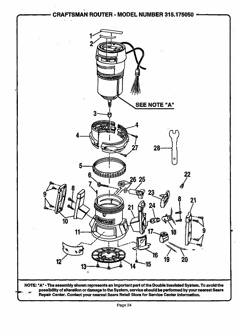
..... CRAFTSMAN ROUTER - MODEL NUMBER 315,175050 ,
SEE NOTE "A"
9
27 28
10
I 26 2522
18
21
9
w_
t
NOTE: "A" - The assembly shown _presents an important part of the Double Insulated System. To avoid the__-. possiblllty of alteration or damage to the System, service should be performed by your nearest Sears
Repslr Center. Contact your nearest Sears Retail Store for Servlce Center information.
Page 24
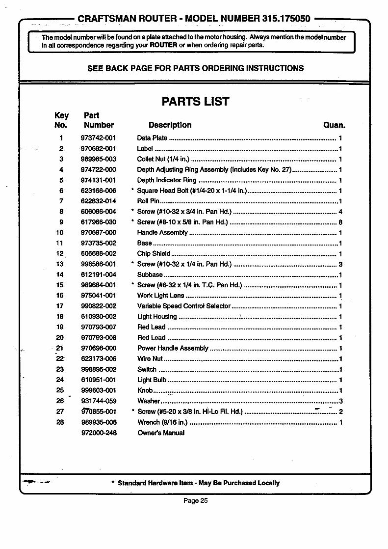
• CRAFTSMAN ROUTER - MODEL NUMBER 315.175050 .
J .-Themodelnumberwillbefoundonaplateattachedtothemotorhousing. Always mention the model number Jin all correspondence regarding your ROUTER or when ordering repair parts.
SEE BACK PAGE FOR PARTS ORDERING INSTRUCTIONS
Key PartNo. Number
1 973742-001
- 2 •970692-001
3 989985-003
4 974722-000
5 974131-001
6 623166-006
7 622832-014
8 606066-004
9 617966-030
10 970697-000
11 973735-002
12 606688-002
13 998586-001
14 612191-004
15 989684-001
16 975041-001
17 990822-002
18 610930-002
19 970793-007
20 970793-008
- 21 970698-000
-22 623173-006
23 999895-002
24 610951-001
25 999603-001
26 931744-059
27 9"70855-001
28 989935-006
972000-248
PARTS LIST
Description Quan.
Data Plate ............................................................................................. 1
Label.................._.............._.__...................................._......................_.....1
Collet Nut (1/4 in.) ................................................................................. 1
Depth Adjusting Ring Assembly (Includes Key No. 27) ......................... 1
Depth Indicator Ring ............................................................................. 1
* Square Head Bolt (#1/4-20 x 1-1/4 in.) .................................................. 1
Roll Pin ................................................................................................... 1
* Screw (#10-32 x 3/4 in. Pan Hd.) .......................................................... 4
* Screw (#8-10 x 5/8 in. Pan Hd.) ............................................................ 8
Handle Assembly .................................................................................. 1
Base ....................................................................................................... 1
Chip Shield ............................................................................................ 1
° Screw (#10-32 x 1/4 in. Pan Hd.) .......................................................... 3
Subbase ................................................................................................. 1
° Screw (#6-32 x 1/4 in. T.C. Pan Hd.) ........................ ............................ 1
Work Ught Lens .................................................................................... 1
Variable Speed Control Selector ........................................................... 1
Ught Housing ................................. ._...................................................... 1
Red Lead .............................................................................................. 1
Red Lead .............................................................................................. 1
Power Handle Assembly ....................................................................... 1
Wire Nut .................................................................................................. 1
Switch .................................................................................................... 1
Ught Bulb .............................................................................................. 1
Knob................................................................_..............._......................_
Washer ................................................................................................... 3
* Screw (#5-20 x 3/8 in. Hi-Lo RI. Hd.). ...................................... ..-...... _....2
Wrench (9/16 in.) .................................................................................. 1
Owner's Manual
* Standard Hardware Item - May Be Purchased Locally
Page 25
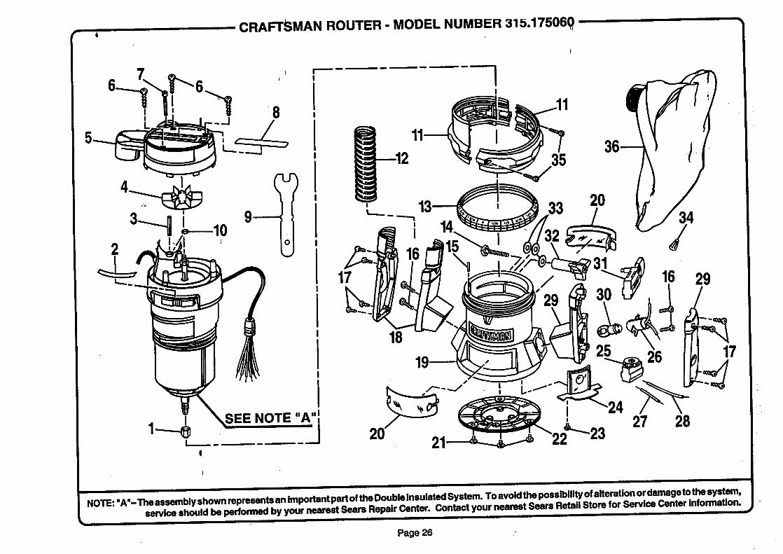
..CRAFTSMAN ROUTER - MODEL NUMBER 315.175060, -
" " eassembi shownre resentsanimportantpartoftheDoublelnsulatedSystem- Toavoidthepossibilityofalterationordamagetothesystem,NOTE: A -Th y P ........... ,- ,---,-- r'_nta_ your nearest Sears Retail Store for Service Center information.
service should be penormea Dy your nearesz _>ears rtepau ,.,u,n_, ....... .
Page 26
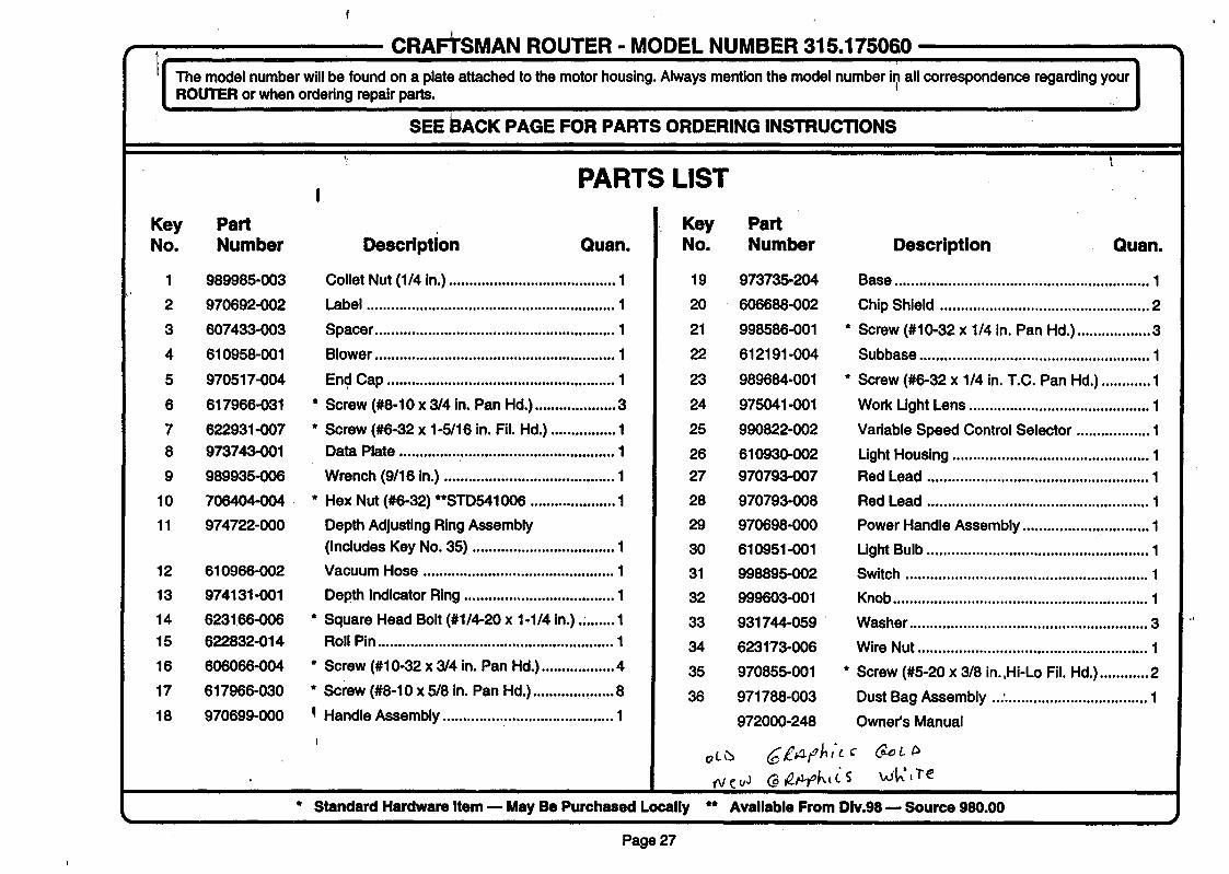
CRAFTSMAN ROUTER - MODEL NUMBER 315.175060
[ The model number will be found on a plate attached to the motor housing. Always menUon the model number il_all correspondence regarding your]ROUTER or when ordering repair parts.
SEE BACK PAGE FOR PARTS ORDERING INSTRUCTIONS
PARTS LIST
Key PartNo. Number Description Quan.
1 989985-003
2 970692-002
3 607433-003
4 610958-001
5 970517-004
6 617966-031 *
7 622931-007 *
8 973743-001
9 989935-006
10 706404-004 *
11 974722-000
Collet Nut (1/4 in.) ......................................... 1
Label ............................................................. 1
Spacer ........................................................... 1
Blower ........................................................... 1
End Cap ........................................................ 1
Screw (#8-10 x 3/4 in. Pan Hd.) .................... 3
Screw (#6-32 x 1-5/16 in. Fil. Hd.) ................ 1
Data Plate ..................................................... 1
Wrench (9/16 in.) .......................................... 1
Hex Nut (#6-32) **STD541006 ..................... 1
Depth Adjusting Ring Assembly
(Includes Key No. 35) ................................... 1
Vacuum Hose ............................................... 1
Depth Indicator Ring ..................................... 1
Square Head Bolt (#1/4-20 x 1-1/4 in.)., ....... 1
Roll Pin .......................................................... 1
Screw (#10-32 x 3/4 in. Pan Hd.) .................. 4
Screw (#8-10 x 5/8 in. Pan Hd.) .................... 8
Handle Assembly .......................................... 1
* Standard Hardware Item _ May Be Purchased Locally
12 610966-002
13 974131-001
14 6231.66-006 *
15 622832-014
16 606066-004 *
17 617966-030 *
18 970699-000 !
I
Key PartNo. Number Description Quan.
19 973735-204
20 606688-002
21 998586-001
22 612191-004
23 989684-001
24 975041-001
25 990822-002
26 610930-002
27 970793-007
28 970793-008
29 970698-000
30 610951-001
31 998895-002
32 999603-001
33 931744-059
34 623173-006
35 970855-001
36 971788-003
972000-248
Base .............................................................. 1
Chip Shield ................................................... 2
* Screw (#10-32 x 1/4 in. Pan Hd.) .................. 3
Subbase ........................................................ 1
* Screw (#6-32 x 1/4 in. T.C. Pan Hd.) ............ 1
Work Light Lens ............................................ 1
Variable Speed Control Selector .................. 1
Light Housing ................................................ 1Red Lead ...................................................... 1
Red Lead ...................................................... 1
Power Handle Assembly ............................... 1
Light Bulb ...................................................... 1
Switch ........................................................... 1
Knob .............................................................. 1
Washer .......................................................... 3
Wire Nut ........................................................ 1
* Screw (#5-20 x 3/8 in.,Hi-Lo Fil. Hd.) ............ 2
Dust Bag Assembly ...'................................... 1
Owner's Manual
** Available From Div.98 -- Source 980.00
Page 27

Forthe repairorreplacementpartsyouneeddelivereddirectlyto yourhomeCall7 am- 7 pro,7 daysaweek1-800-366-PART
(1-800-366-7278)
ForrepairserviceCall24 hoursa day,7 daysa week
1-800-4-REPAIR(1-800-473-7247)
P,EPAIRSERVICES
Forthelocationofa
SearsPartsandRepairCenterinyourareaCall24 hours a day,7 daysa week
1-800-488-1222m
ImBBElm
SEARSb
IBEBBBE,,,,..'-'-
The modelrjumberof thistoolwill be roundona serial plateattachedto the motorhousing.Whenrequestingserviceororderingpads, alwaysprovidethe followinginformation:
• ProductName • MOdelNumberRouter 315.175040
315.175050315.175060
SE/AJ:I$_PartName • Part Number
America's Repair Specialists