Embed Size (px)
Citation preview
June, 2002
GM338/GM398Mobile Radios
Basic Service Manual
6804112J17-D

Computer Software CopyrightsThe Motorola products described in this manual may include copyrighted Motorola computer programs storedin semiconductor memories or other media. Laws in the United States and other countries preserve forMotorola certain exclusive rights for copyrighted computer programs, including the exclusive right to copy orreproduce in any form, the copyrighted computer program. Accordingly, any copyrighted Motorola computerprograms contained in the Motorola products described in this manual may not be copied or reproduced inany manner without the express written permission of Motorola. Furthermore, the purchase of Motorola prod-ucts shall not be deemed to grant, either directly or by implication, estoppel or otherwise, any license underthe copyrights, patents or patent applications of Motorola, except for the normal non-exclusive royalty-freelicense to use that arises by operation of law in the sale of a product.
i
SAFETY INFORMATION
SAFETY AND GENERAL INFORMATION
Information and Instructions on RF Energy Exposure and Product SafetyREAD THIS IMPORTANT INFORMATION ON SAFE AND EFFICIENT OPERATION BEFOREINSTALLING AND USING YOUR MOTOROLA MOBILE TWO-WAY RADIO IN A VEHICLE OR ASA CONTROL STATION.
Compliance with RF Energy Exposure StandardsYour Motorola two-way radio is designed and tested to comply with a number of national andinternational standards and guidelines (listed below) regarding human exposure to radio frequencyelectromagnetic energy. This radio complies with the IEEE (FCC) and ICNIRP exposure limits at dutycycles of up to 50% talk-50% listen and should be used for occupational use only. In terms ofmeasuring RF energy for compliance with the FCC exposure guidelines, your radio radiatesmeasurable RF energy only while it is transmitting (during talking), not when it is receiving (listening)or in standby mode.
Your Motorola two-way radio complies with the following RF energy exposure standards andguidelines:
• United States Federal Communications Commission, Code of Federal Regulations; 47CFR part2 sub-part J
• American National Standards Institute (ANSI) / Institute of Electrical and Electronic Engineers(IEEE) C95. 1-1992
• Institute of Electrical and Electronic Engineers (IEEE) C95.1-1999 Edition• International Commission on Non-Ionizing Radiation Protection (ICNIRP) 1998• Ministry of Health (Canada) Safety Code 6. Limits of Human Exposure to Radio frequency Elec-
tromagnetic Fields in the Frequency Range from 3 kHz to 300 GHz, 1999• Australian Communications Authority Radiocommunications (Electromagnetic Radiation -
Human Exposure) Standard 2001• ANATEL, Brazil Regulatory Authority, Resolution 256 (April 11, 2001) "additional requirements
for SMR, cellular and PCS product certification."
Operational Instructions and Training GuidelinesTo ensure optimal performance and compliance with the RF energy exposure limits in the abovestandards and guidelines, users should transmit no more than 50% of the time and always adhere tothe following procedures:
Transmit and Receive• To transmit (talk), push the Push-To-Talk (PTT) button; to receive, release the PTT button.• Transmit only when people outside the vehicle are at least the minimum lateral distance away,
as shown in Table 1, from a properly installed, externally-mounted antenna.
ii SAFETY INFORMATION
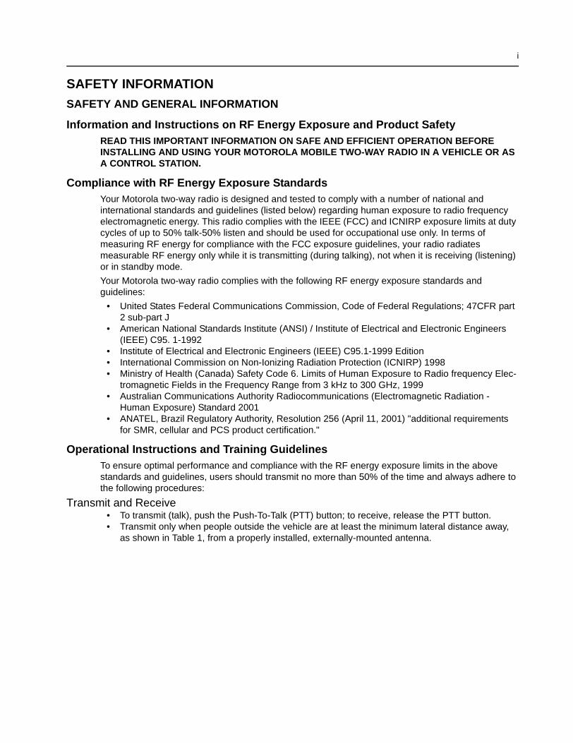
Table 1 lists the minimum lateral distance for bystanders in an uncontrolled environment from thetransmitting antenna at several different ranges of rated radio power for mobile radios installed in avehicle.
Mobile Antennas• Install antennas at the center of the roof or the center of the trunk deck. These mobile antenna
installation guidelines are limited to metal body vehicles.• The antenna installation must additionally be in accordance with:
a. The requirements of the antenna manufacturer/supplier
b. Instructions in the Radio Installation Manual
• Use only Motorola approved supplied antenna or Motorola approved replacementantenna. Unauthorized antennas, modifications, or attachments could damage the radio andmay violate FCC regulations.
Approved AccessoriesFor a list of approved Motorola accessories please contact your dealer, or local Motorolarepresentative.
Fixed Site AntennasIf mobile radio equipment is installed at a fixed location and operated as a control station or as a fixedunit, the antenna installation must comply with the following requirements in order to ensure optimalperformance and compliance with the RF energy exposure limits in the above standards andguidelines.
• The antenna should be mounted outside the building on the roof or a tower if at all possible.• As with all fixed site antenna installations, it is the responsibility of the licensee to manage the
site in accordance with applicable regulatory requirements and may require additional compli-ance actions such as site survey measurements, signage, and site access restrictions in order toinsure that exposure limits are not exceeded.
ELECTROMAGNETIC INTERFERENCE/COMPATIBILITY
Table 1: Rated Power and Lateral Distance
Rated Power of Vehicle-InstalledMobile Two-way Radio
Minimum Lateral Distancefrom Transmitting
Antenna
Less than 7 watts 8 inches (20 centimeters)
7 to 15 watts 1 foot (30 centimeters)
16 to 50 watts 2 feet (60 centimeters)
51 to 110 watts 3 feet (90 centimeters)
NOTE Nearly every electronic device is susceptible to electromagnetic interference (EMI) if inadequatelyshielded, designed, or otherwise configured for electromagnetic compatibility. It may be necessaryto conduct compatibility testing to determine if any electronic equipment used in or around vehiclesor near fixed antenna sites is sensitive to external RF energy and if any procedures need to be fol-lowed to eliminate or mitigate the potential for interaction between the radio transmitter and theequipment or device.
SAFETY INFORMATION iii
FacilitiesTo avoid electromagnetic interference and/or compatibility conflicts, turn off your radio in any facilitywhere posted notices instruct you to do so. Hospitals or health care facilities may be using equipmentthat is sensitive to external RF energy.
VehiclesTo avoid possible interaction between the radio transmitter and any vehicle electronic controlmodules, for example, ABS, engine, or transmission controls, we recommend that the radio beinstalled by an experienced installer and that the following precautions be used when installing theradio:
1. Refer to any manufacturer’s instructions or other technical bulletins or recommendations on radio installa-tion.
2. Before installing the radio, determine the location of the electronic control modules and their harnesses inthe vehicle.
3. Route all radio wiring, including the antenna transmission line, as far away as possible from the electroniccontrol units and associated wiring.
Driver SafetyCheck the laws and regulations on the use of radios in the area where you drive. Always obey them.
When using your radio while driving, please:
• Give full attention to driving and to the road.• Pull off the road and park before making or answering a call if driving conditions so require.
OPERATIONAL WARNINGS
For Vehicles With an Air BagDo not place a mobile radio in the area over an air bag or in the air bag deploymentarea. Air bags inflate with great force. If a radio is placed in the air bag deploymentarea and the air bag inflates, the radio may be propelled with great force and causeserious injury to occupants of the vehicle.
Potentially Explosive AtmospheresTurn off your radio prior to entering any area with a potentially explosive atmosphere. Sparks in apotentially explosive atmosphere can cause an explosion or fire resulting in bodily injury or evendeath.
Blasting Caps and AreasTo avoid possible interference with blasting operations, turn off your radio when you are nearelectrical blasting caps, in a blasting area, or in areas posted: “Turn off two-way radio.” Obey all signsand instructions.
For radios installed in vehicles fuelled by liquefied petroleum gas in the U.S., refer to the (U.S.) National FireProtection Association standard, NFPA 58, for storage, handling, and/or container information. For a copy of theLP-gas standard, NFPA 58, contact the National Fire Protection Association, One Battery Park, Quincy, MA.
NOTE The areas with potentially explosive atmospheres referred to above include fueling areassuch as below decks on boats, fuel or chemical transfer or storage facilities, and areaswhere the air contains chemicals or particles, such as grain, dust or metal powders. Areaswith potentially explosive atmospheres are often but not always posted.
!W A R N I N G
!

iv SAFETY INFORMATION
THIS PAGE INTENTIONALLY LEFT BLANK
v
Table of Contents
Section 1 Introduction
1.0 Scope of Manual ..................................................................................................1-12.0 Warranty and Service Support.............................................................................1-1
2.1 Warranty Period and Return Instructions .......................................................1-12.2 After Warranty Period .....................................................................................1-12.3 Piece Parts Availability ...................................................................................1-22.4 Technical Support...........................................................................................1-2
3.0 Radio Model Information......................................................................................1-3
Section 2 Maintenance
1.0 Introduction ..........................................................................................................2-12.0 Preventive Maintenance ......................................................................................2-1
2.1 Inspection .......................................................................................................2-12.2 Cleaning Procedures ......................................................................................2-1
3.0 Safe Handling of CMOS and LDMOS Devices ....................................................2-24.0 Repair Procedures and Techniques — General ..................................................2-35.0 Disassembling and Reassembling the Radio — General ....................................2-36.0 Radio Disassembly - Detailed..............................................................................2-4
6.1 Control Head Removal ...................................................................................2-46.2 Top Cover Removal........................................................................................2-56.3 Transceiver Board Removal ...........................................................................2-66.4 Disassembly of Control Heads .......................................................................2-7
7.0 Radio Assembly ...................................................................................................2-97.1 Control Heads - GM338 and GM398..............................................................2-97.2 Radio Chassis And Transceiver Board...........................................................2-97.3 Control Head Fitting........................................................................................2-9
8.0 Radio Exploded Mechanical Views and Parts Lists ...........................................2-108.1 Radio Assembly............................................................................................2-108.2 Control Head - GM338 .................................................................................2-118.3 Control Head - GM398 .................................................................................2-12
9.0 Service Aids .......................................................................................................2-1310.0 Test Equipment..................................................................................................2-1411.0 Programming/Test Cable - RKN4083_ .............................................................2-15
Section 3 Transceiver Performance Testing
1.0 General ................................................................................................................3-12.0 Setup....................................................................................................................3-13.0 RF Test Mode ......................................................................................................3-2
vi
Section 4 Radio Tuning and Programming
1.0 Introduction ..........................................................................................................4-12.0 CPS Programming Setup ....................................................................................4-13.0 Radio Tuning Setup .............................................................................................4-3
3.1 Initial Test Equipment Control Settings ..........................................................4-3
Section 5 Power Up Self-Test
1.0 Error Codes .........................................................................................................5-1
Section 6 Model Chart and Test Specification
1.0 Low Power Radios...............................................................................................6-11.1 Model Chart (VHF 136-174 MHz)...................................................................6-11.2 Model Chart (UHF Band 1, 403-470 MHz) .....................................................6-21.3 Model Chart (UHF Band 2, 450-527 MHz) .....................................................6-31.4 Model Chart (Low Band, 29.7-50.0 MHz).......................................................6-31.5 Specifications ................................................................................................6-4
2.0 High Power Radios ..............................................................................................6-62.1 Model Chart (VHF 136-174 MHz)...................................................................6-62.2 Model Chart (UHF Band 1, 403-470 MHz) .....................................................6-62.3 Model Chart (UHF Band 2, 450-520 MHz) .....................................................6-72.4 Model Chart (UHF Band 1, LDMOS, 403-470 MHz) ......................................6-72.5 Model Chart (UHF Band 2, LDMOS, 450-520 MHz) ......................................6-82.6 Specifications ................................................................................................6-9
Glossary of Terms .................................................................................... G-1
1-1
Section 1
INTRODUCTION
1.0 Scope of Manual
This manual is intended for use by service technicians familiar with similar types of equipment. Itcontains service information required for the equipment described and is current as of the printingdate. Changes which occur after the printing date may be incorporated by a complete manualrevision or alternatively as additions.
2.0 Warranty and Service Support
Motorola offers support which includes: full exchange and/or repair of the product during thewarranty period; and service/ repair or spare parts support out of warranty. Any “return forexchange” or “return for repair” to an authorized Motorola Dealer must be accompanied by aWarranty Claim Form. Warranty Claim Forms are obtained by contacting an Authorized MotorolaDealer.
2.1 Warranty Period and Return Instructions
The terms and conditions of warranty are defined fully in the Motorola Dealer or Distributor orReseller contract. These conditions may change from time to time, and the following subsectionsare for guidance purposes only.
In instances where the product is covered under a “return for replacement” or “return for repair”warranty, a check of the product should be performed prior to shipping the unit back to Motorola.This is to ensure that the product has been correctly programmed or has not been subjected todamage outside the terms of the warranty.
Prior to shipping any radio back to the appropriate Motorola warranty depot, please contactCustomer Resources. All returns must be accompanied by a Warranty Claim Form, available fromyour Customer Resources representative. Products should be shipped back in the originalpackaging, or correctly packaged to ensure that no damage occurs in transit.
2.2 After Warranty Period
After the Warranty period, Motorola continues to support its products in two ways:
1. Motorola's Accessories and Aftermarket Division (AAD) offers a repair service to both endusers and dealers at competitive prices.
2. AAD supplies individual parts and modules that can be purchased by dealers who are techni-cally capable of performing fault analysis and repair.
NOTE Before operating or testing these units, please read the Safety Information section in thefront of this manual.
1-2 Warranty and Service Support
2.3 Piece Parts Availability
Some replacement parts, spare parts, and/or product information can be ordered directly. If acomplete Motorola part number is assigned to the part, it is available from Motorola’s Accessoriesand Aftermarket Division (AAD). If no part number is assigned, the part is not normally availablefrom Motorola. If the part number is appended with an asterisk, the part is serviceable by MotorolaDepot only. If a parts list is not included, this generally means that no user-serviceable parts areavailable for that kit or assembly.
All orders for parts/information should include the complete Motorola identification number. All partorders should be directed to your local AAD office. Please refer to your latest price pages.
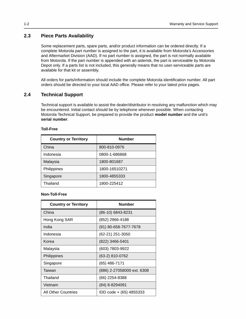
2.4 Technical Support
Technical support is available to assist the dealer/distributor in resolving any malfunction which maybe encountered. Initial contact should be by telephone wherever possible. When contactingMotorola Technical Support, be prepared to provide the product model number and the unit’sserial number .
Toll-Free
Non-Toll-Free
Country or Territory Number
China 800-810-0976
Indonesia 0800-1-686868
Malaysia 1800-801687
Philippines 1800-16510271
Singapore 1800-4855333
Thailand 1800-225412
Country or Territory Number
China (86-10) 6843-8231
Hong Kong SAR (852) 2966-4188
India (91) 80-658-7677-7678
Indonesia (62-21) 251-3050
Korea (822) 3466-5401
Malaysia (603) 7803-9922
Philippines (63-2) 810-0762
Singapore (65) 486-7171
Taiwan (886) 2-27058000 ext. 6308
Thailand (66) 2254-8388
Vietnam (84) 8-8294091
All Other Countries IDD code + (65) 4855333
1-3 Radio Model Information
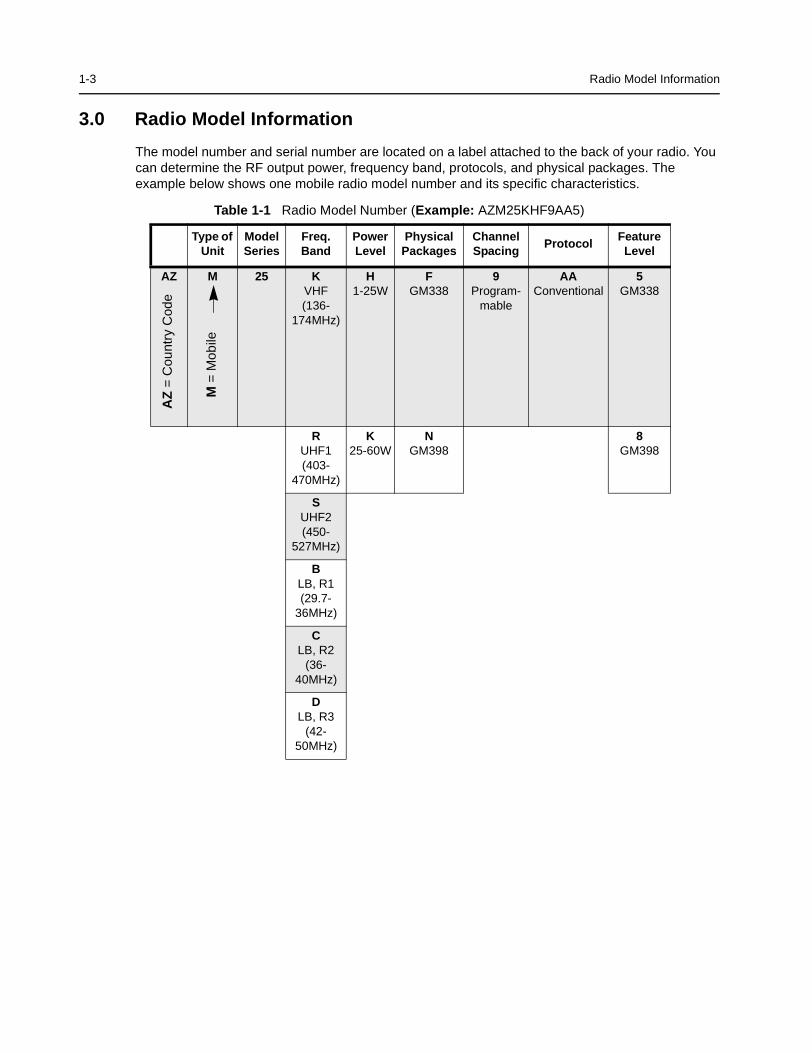
3.0 Radio Model Information
The model number and serial number are located on a label attached to the back of your radio. Youcan determine the RF output power, frequency band, protocols, and physical packages. Theexample below shows one mobile radio model number and its specific characteristics.
Table 1-1 Radio Model Number (Example: AZM25KHF9AA5)
Type ofUnit
ModelSeries
Freq.Band
PowerLevel
PhysicalPackages
ChannelSpacing
ProtocolFeature
Level
AZ M 25 KVHF(136-
174MHz)
H1-25W
FGM338
9Program-
mable
AAConventional
5GM338
RUHF1(403-
470MHz)
K25-60W
NGM398
8GM398
SUHF2(450-
527MHz)
BLB, R1(29.7-
36MHz)
CLB, R2
(36-40MHz)
DLB, R3
(42-50MHz)
AZ
=C
ount
ryC
ode
M=
Mob
ile

1-4 Radio Model Information
THIS PAGE INTENTIONALLY LEFT BLANK
2-1
Section 2
MAINTENANCE
1.0 Introduction
This chapter provides details about the following:
• Preventive maintenance (inspection and cleaning).
• Safe handling of CMOS and LDMOS devices.
• Disassembly and reassembly of the radio.
• Repair procedures and techniques.
2.0 Preventive Maintenance
The radios do not require a scheduled preventive maintenance program; however, periodic visualinspection and cleaning is recommended.
2.1 Inspection
Check that the external surfaces of the radio are clean, and that all external controls and switchesare functional. It is not recommended to inspect the interior electronic circuitry.
2.2 Cleaning Procedures
The following procedures describe the recommended cleaning agents and the methods to be usedwhen cleaning the external and internal surfaces of the radio. External surfaces include the frontcover, housing assembly and battery case. These surfaces should be cleaned whenever a periodicvisual inspection reveals the presence of smudges, grease, and/or grime.
The only recommended agent for cleaning the external radio surfaces is a 0.5% solution of a milddishwashing detergent in water. The only factory recommended liquid for cleaning the printed circuitboards and their components is isopropyl alcohol (70% by volume).
Cleaning External Plastic Surfaces
Apply the 0.5% detergent-water solution sparingly with a stiff, non-metallic, short-bristled brush towork all loose dirt away from the radio. Use a soft, absorbent, lintless cloth or tissue to remove thesolution and dry the radio. Make sure that no water remains entrapped near the connectors, cracks,or crevices.
NOTE Internal surfaces should be cleaned only when the radio is disassembled for service orrepair.
CAUTION: The effects of certain chemicals and their vapors can have harmful results on certain plas-tics. Avoid using aerosol sprays, tuner cleaners, and other chemicals.!
2-2 Safe Handling of CMOS and LDMOS Devices
Cleaning Internal Circuit Boards and Components
Isopropyl alcohol (70%) may be applied with a stiff, non-metallic, short-bristled brush to dislodgeembedded or caked materials located in hard-to-reach areas. The brush stroke should direct thedislodged material out and away from the inside of the radio. Make sure that controls or tunablecomponents are not soaked with alcohol. Do not use high-pressure air to hasten the drying processsince this could cause the liquid to collect in unwanted places. After completing of the cleaningprocess, use a soft, absorbent, lintless cloth to dry the area. Do not brush or apply any isopropylalcohol to the frame, front cover, or back cover.
3.0 Safe Handling of CMOS and LDMOS Devices
Complementary metal-oxide semiconductor (CMOS) devices are used in this family of radios, andare susceptible to damage by electrostatic or high voltage charges. Damage can be latent, resultingin failures occurring weeks or months later. Therefore, special precautions must be taken to preventdevice damage during disassembly, troubleshooting, and repair.
Handling precautions are mandatory for CMOS circuits and are especially important in low humidityconditions. DO NOT attempt to disassemble the radio without first referring to the followingCAUTION statement.
NOTE Always use a fresh supply of alcohol and a clean container to prevent contamination bydissolved material (from previous usage).
CAUTION: This radio contains static-sensitive devices. Do not open the radio unless you are properlygrounded. Take the following precautions when working on this unit:
• Store and transport all CMOS devices in conductive material so that all exposedleads are shorted together. Do not insert CMOS devices into conventional plastic“snow” trays used for storage and transportation of other semiconductor devices.
• Ground the working surface of the service bench to protect the CMOS device. Werecommend using the Motorola Static Protection Assembly (part number0180386A82), which includes a wrist strap, two ground cords, a table mat, and afloor mat.
• Wear a conductive wrist strap in series with a 100k resistor to ground.(Replacement wrist straps that connect to the bench top covering are Motorola partnumber RSX4015_).
• Do not wear nylon clothing while handling CMOS devices.
• Do not insert or remove CMOS devices with power applied. Check all powersupplies used for testing CMOS devices to be certain that there are no voltagetransients present.
• When straightening CMOS pins, provide ground straps for the apparatus used.
• When soldering, use a grounded soldering iron.
• If at all possible, handle CMOS devices by the package and not by the leads. Priorto touching the unit, touch an electrical ground to remove any static charge that youmay have accumulated. The package and substrate may be electrically common. Ifso, the reaction of a discharge to the case would cause the same damage astouching the leads.
!
Repair Procedures and Techniques — General 2-3
4.0 Repair Procedures and Techniques — General
Parts Replacement and Substitution
When damaged parts are replaced, identical parts should be used. If the identical replacement partis not locally available, check the parts list for the proper Motorola part number and order the partfrom the nearest Motorola Communications parts center listed in the “Piece Parts” section of thismanual.
Rigid Circuit Boards
This family of radios uses bonded, multi-layer, printed circuit boards. Since the inner layers are notaccessible, some special considerations are required when soldering and unsoldering components.The printed-through holes may interconnect multiple layers of the printed circuit. Therefore, exercisecare to avoid pulling the plated circuit out of the hole.
When soldering near the 20-pin and 40-pin connectors:
• Avoid accidentally getting solder in the connector.
• Be careful not to form solder bridges between the connector pins.
• Examine your work closely for shorts due to solder bridges.
5.0 Disassembling and Reassembling the Radio — General
Since these radios may be disassembled and reassembled with the use of only four (board tocasting) screws, it is important to pay particular attention to the snaps and tabs, and how parts alignwith each other.
The following tools are required for disassembling the radio:
• Small flat blade screwdriver
• Dismantling Tool (Motorola Part No. 6686119B01)
• TORX™ T20 screwdriver
If a unit requires more complete testing or service than is customarily performed at the basic level,send this unit to a Motorola Authorized Service Center. (See Chapter 1 for a list of authorizedservice centers.)
The following disassembly procedures should be performed only if necessary:
2-4 Radio Disassembly - Detailed
6.0 Radio Disassembly - Detailed
The procedure to remove and replace a Control Head, Top Cover or Transceiver Board is similar forall models of radio. A typical procedure is therefore shown followed by specific disassemblyprocedures for Control Heads on radio models.
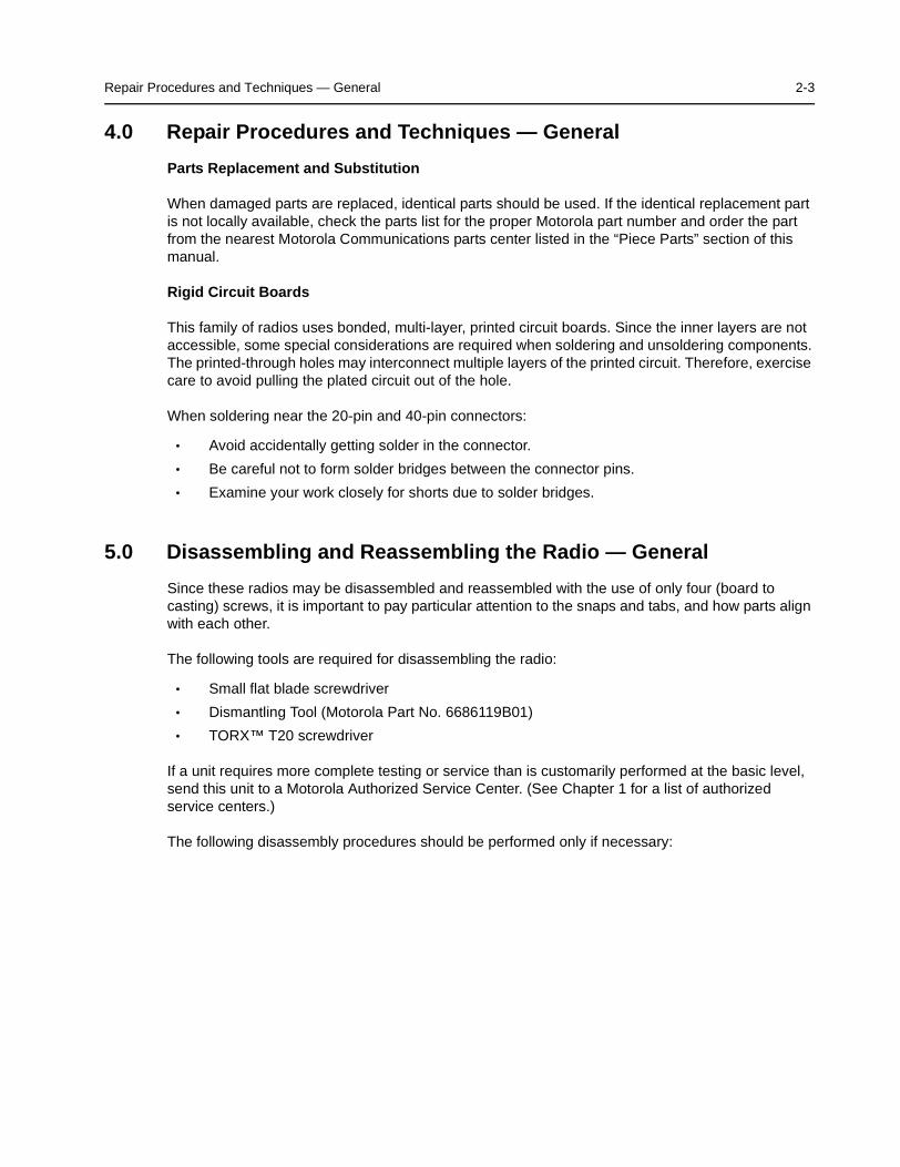
6.1 Control Head Removal
1. Insert the dismantling tool in the groove between the control head and the radio assembly asshown in Figure 2-1.
2. Press on the dismantling tool until the snap connectors on the side of the control head releasefrom the radio assembly.
Figure 2-1 Typical Control Head Removal.
3. Pull the control head away from the radio assembly as shown in Figure 2-2.
DismantlingTool
ZWG0130209-O
Radio Disassembly - Detailed 2-5
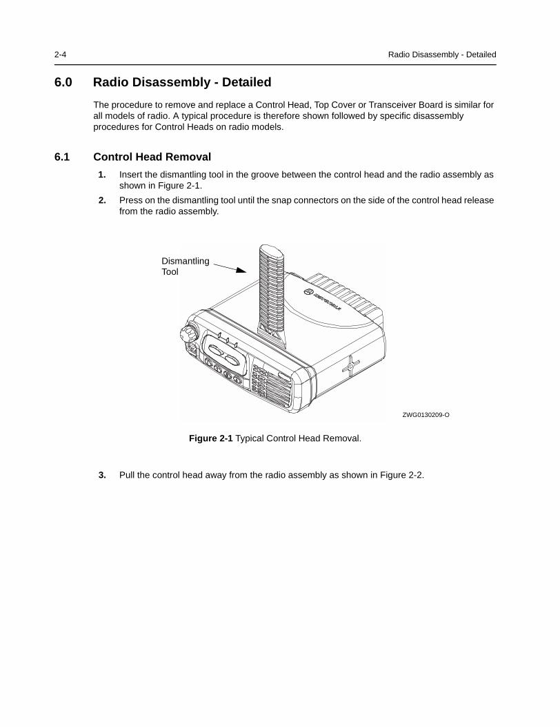
Figure 2-2 Flexible Connection Removal
4. Remove the flexible connection from the socket on the control head board.
6.2 Top Cover Removal
1. Insert the dismantling tool in the middle of the radio assembly side groove as shown inFigure 2-3.
2. Press on the dismantling tool until the snap connectors on the side of the cover release fromthe radio chassis.
3. Lift the top cover from the chassis.
Figure 2-3 Top Cover Removal.
FlexibleConnection
ZWG0130210-O
DismantlingTool
ZWG0130211-O
2-6 Radio Disassembly - Detailed
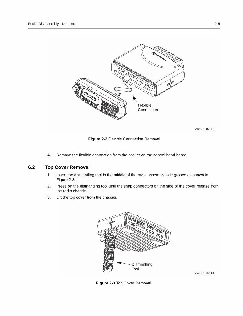
6.3 Transceiver Board Removal
1. Remove six screws from the diecast cover using the T20 TORX™ driver as shown inFigure 2-4.
2. Lift the cover from the chassis.
Figure 2-4 Diecast Cover Removal.
3. Slowly lift the transceiver board on the edge at the front of the radio (the edge that mates withthe control head) and pull gently toward the front of the radio as shown in Figure 2-5. Takecare to slide the antenna connector and power connector out of the chassis towards the front.
Figure 2-5 Transceiver Board Removal
CAUTION: The thermal grease or pads can act as an adhesive and cause the leads of the heatdissipating devices to be over stressed if the board is lifted too quickly.
DiecastCover
Screws (6)
RadioChassis
ZWG0130212-O
!
Lift
AntennaConnector
ZWG0130213-O
Radio Disassembly - Detailed 2-7
6.4 Disassembly of Control Heads
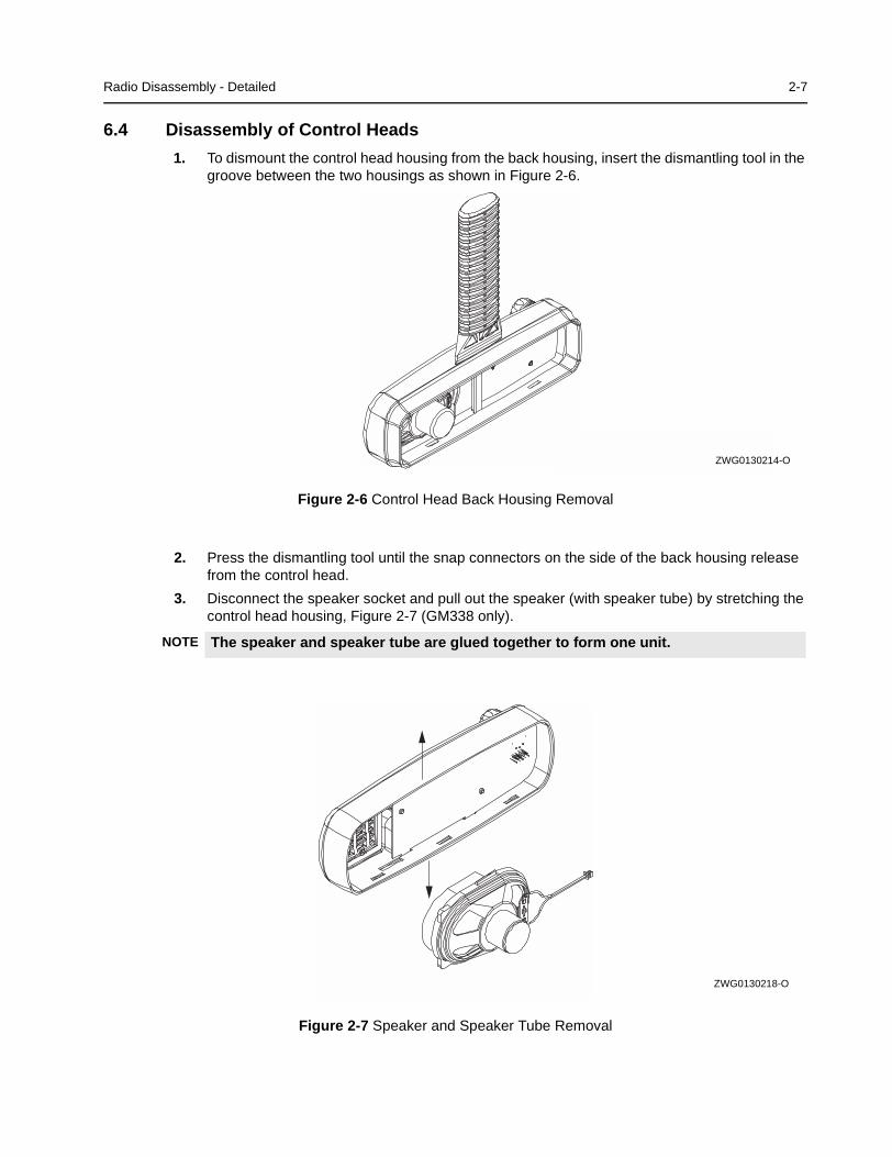
1. To dismount the control head housing from the back housing, insert the dismantling tool in thegroove between the two housings as shown in Figure 2-6.
Figure 2-6 Control Head Back Housing Removal
2. Press the dismantling tool until the snap connectors on the side of the back housing releasefrom the control head.
3. Disconnect the speaker socket and pull out the speaker (with speaker tube) by stretching thecontrol head housing, Figure 2-7 (GM338 only).
Figure 2-7 Speaker and Speaker Tube Removal
NOTE The speaker and speaker tube are glued together to form one unit.
ZWG0130214-O
ZWG0130218-O
2-8 Radio Disassembly - Detailed
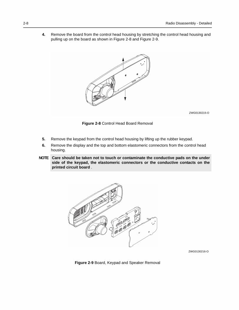
4. Remove the board from the control head housing by stretching the control head housing andpulling up on the board as shown in Figure 2-8 and Figure 2-9.
Figure 2-8 Control Head Board Removal
5. Remove the keypad from the control head housing by lifting up the rubber keypad.
6. Remove the display and the top and bottom elastomeric connectors from the control headhousing.
Figure 2-9 Board, Keypad and Speaker Removal
NOTE Care should be taken not to touch or contaminate the conductive pads on the underside of the keypad, the elastomeric connectors or the conductive contacts on theprinted circuit board .
ZWG0130215-O
ZWG0130216-O
Radio Assembly 2-9
7.0 Radio Assembly
7.1 Control Heads - GM338 and GM398
1. On the GM338 only, locate the display in the control head ensuring that the two cut-outs in thedisplay are aligned with their corresponding indentations, then press the display into place.Insert the top and bottom elastomeric connector strips into the spaces above and below thedisplay respectively.
2. Fit the rubber keypad onto the board ensuring that the ON/OFF control and microphone onthe board locate correctly with the cut-outs in the keypad.
3. On the board, rotate the ON/OFF control spindle fully counter-clockwise.
4. Also, rotate the volume knob on the front housing fully counter-clockwise.
5. Align the board with the control head, inserting the ON/OFF control spindle and microphoneconnector through the holes in the control head.
6. Ensure that the keypad, ON/OFF control spindle and microphone connector are aligned withthe control head then press the board into place until it clicks.
7. On the GM338, insert the speaker tube and speaker into the control head and press it in untilit clicks. Connect the speaker connector to the board.
7.2 Radio Chassis And Transceiver Board
1. Inspect the transceiver board chassis and if required reapply thermal grease to the heatsinkarea on the chassis and heat dissipating devices. You may have to remove damaged thermalpads from the chassis and devices prior to applying the grease.
2. Insert the transceiver board at an angle (approximately 30°) into the chassis taking care toslide the antenna connector and accessory connector into their cut-outs in the chassis.
3. Lower the transceiver board onto the chassis and align the two locating holes in the boardwith the locating pins in the chassis.
4. Secure the cover to the chassis with the six screws previously removed.
5. Torque the six screws to 1.9 NM (17 in lbs) using the T20 TORX™ driver. Begin with the twoscrews located in the middle of the chassis followed by the four outer screws. Since thescrews usually take a set, torque the screws a second time (1.9 NM) in the same order.
6. Refit the top cover over the assembled radio chassis. Press the cover down until it snaps intoplace.
7.3 Control Head Fitting
1. Align the “0” mark on the flex with the “0” mark on the chassis to the socket on the radioassembly as shown in Figure 2-2.
2. Check that the back housing o-ring seal is undamaged and fitted in the groove. Replace theseal if it is damaged (refer to the exploded view diagrams and parts list).
3. Fit the back housing to the control head. Ensure that the tags on the back housing align withthe snap catch grooves on the control head. Press the back housing into place until it snapsinto place.
4. Check that the radio chassis o-ring seal is undamaged and fitted in the groove on the chassisassembly. Replace the seal if it is damaged.
NOTE Care should be taken not to touch or contaminate the conductive pads on the under-side of the display and the elastomeric connectors (GM338 only) .
2-10 Radio Exploded Mechanical Views and Parts Lists
8.0 Radio Exploded Mechanical Views and Parts Lists
8.1 Radio Assembly
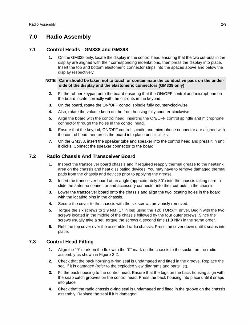
Figure 2-10 Radio Assembly
Item No. Description Part Number
1 Chassis 25W 2786082B02
2 Gasket, Controlhead 3202620Y01
3 Main PCB (items 4, 5 and 6 included)
4 Antenna Connector with Gasket, BNC 0986166B01
5 Power Connector 0986165B01
6 Connector 20 PIN 0986105B01
7 Connector Assembly 2886122B02
8 Gasket Cover 3202607Y01
9 Connector Housing (Optional extra) 1580922V01
10 Gasket Accessory Connector (Optional extra) 3202606Y01
11 Gasket Cover 25W 3286085B01
12 Cover 25W 1586084B01
13 Cover, Plastic 25W 1586083B01
14 Screw T20, 6x (M4) 0310911A30
15 Screw T8 Power Device Fastner (some models only) 0310911A12
16 Silicon Pressure pad, Power devices (25W cover only) 7586187B01
ZWG0130202-A
11
12
13
9
10
1
2
3
456
7
8
14
15
16
Radio Exploded Mechanical Views and Parts Lists 2-11
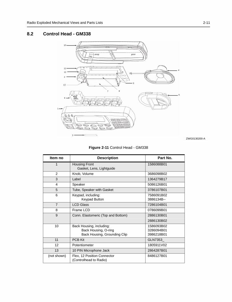
8.2 Control Head - GM338
Figure 2-11 Control Head - GM338
Item no Description Part No.
1 Housing FrontGasket, Lens, Lightguide
1586088B01
2 Knob, Volume 3686098B02
3 Label 1364279B17
4 Speaker 5086126B01
5 Tube, Speaker with Gasket 3786107B01
6 Keypad, including:Keypad Button
7586091B023886134B--
7 LCD Glass 7286104B01
8 Frame LCD 0786099B01
9 Conn. Elastomeric (Top and Bottom) 2886130B01
2886130B02
10 Back Housing, including:Back Housing, O-ringBack Housing, Grounding Clip
1586093B023286094B013986218B01
11 PCB Kit GLN7353_
12 Potentiometer 1805911V02
13 10 PIN Microphone Jack 2864287B01
(not shown) Flex, 12 Position Connector(Controlhead to Radio)
8486127B01
ZWG0130200-A
1
2
3
4
5
6
7 8
10
11
12
139
2-12 Radio Exploded Mechanical Views and Parts Lists
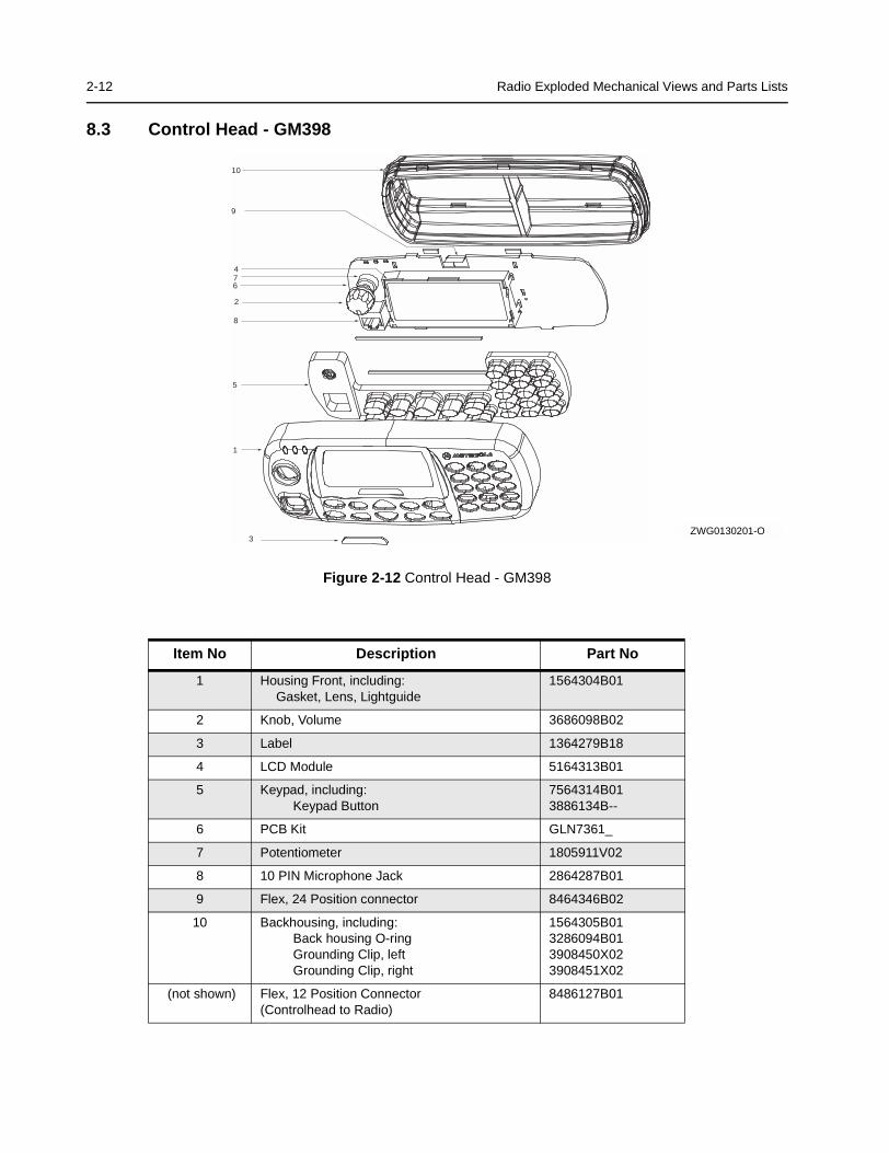
8.3 Control Head - GM398
Figure 2-12 Control Head - GM398
Item No Description Part No
1 Housing Front, including:Gasket, Lens, Lightguide
1564304B01
2 Knob, Volume 3686098B02
3 Label 1364279B18
4 LCD Module 5164313B01
5 Keypad, including:Keypad Button
7564314B013886134B--
6 PCB Kit GLN7361_
7 Potentiometer 1805911V02
8 10 PIN Microphone Jack 2864287B01
9 Flex, 24 Position connector 8464346B02
10 Backhousing, including:Back housing O-ringGrounding Clip, leftGrounding Clip, right
1564305B013286094B013908450X023908451X02
(not shown) Flex, 12 Position Connector(Controlhead to Radio)
8486127B01
1
2
3
5
67
8
9
10
4
ZWG0130201-O
Service Aids 2-13
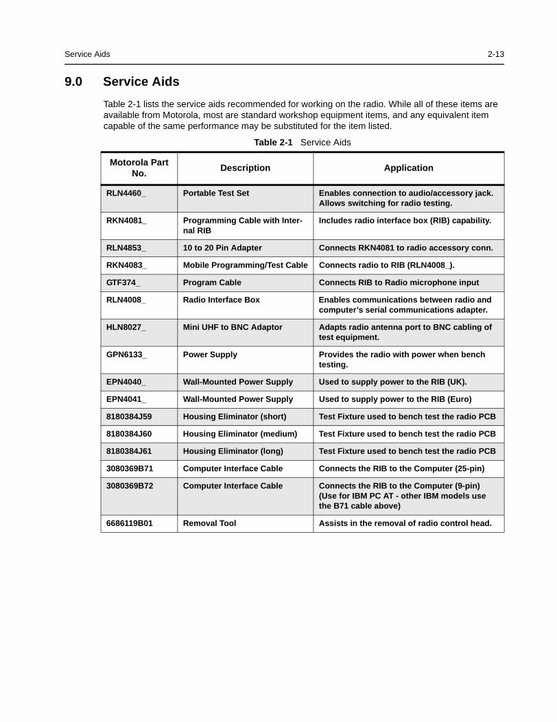
9.0 Service Aids
Table 2-1 lists the service aids recommended for working on the radio. While all of these items areavailable from Motorola, most are standard workshop equipment items, and any equivalent itemcapable of the same performance may be substituted for the item listed.
Table 2-1 Service Aids
Motorola PartNo.
Description Application
RLN4460_ Portable Test Set Enables connection to audio/accessory jack.Allows switching for radio testing.
RKN4081_ Programming Cable with Inter-nal RIB
Includes radio interface box (RIB) capability.
RLN4853_ 10 to 20 Pin Adapter Connects RKN4081 to radio accessory conn.
RKN4083_ Mobile Programming/Test Cable Connects radio to RIB (RLN4008_).
GTF374_ Program Cable Connects RIB to Radio microphone input
RLN4008_ Radio Interface Box Enables communications between radio andcomputer’s serial communications adapter.
HLN8027_ Mini UHF to BNC Adaptor Adapts radio antenna port to BNC cabling oftest equipment.
GPN6133_ Power Supply Provides the radio with power when benchtesting.
EPN4040_ Wall-Mounted Power Supply Used to supply power to the RIB (UK).
EPN4041_ Wall-Mounted Power Supply Used to supply power to the RIB (Euro)
8180384J59 Housing Eliminator (short) Test Fixture used to bench test the radio PCB
8180384J60 Housing Eliminator (medium) Test Fixture used to bench test the radio PCB
8180384J61 Housing Eliminator (long) Test Fixture used to bench test the radio PCB
3080369B71 Computer Interface Cable Connects the RIB to the Computer (25-pin)
3080369B72 Computer Interface Cable Connects the RIB to the Computer (9-pin)(Use for IBM PC AT - other IBM models usethe B71 cable above)
6686119B01 Removal Tool Assists in the removal of radio control head.
2-14 Test Equipment
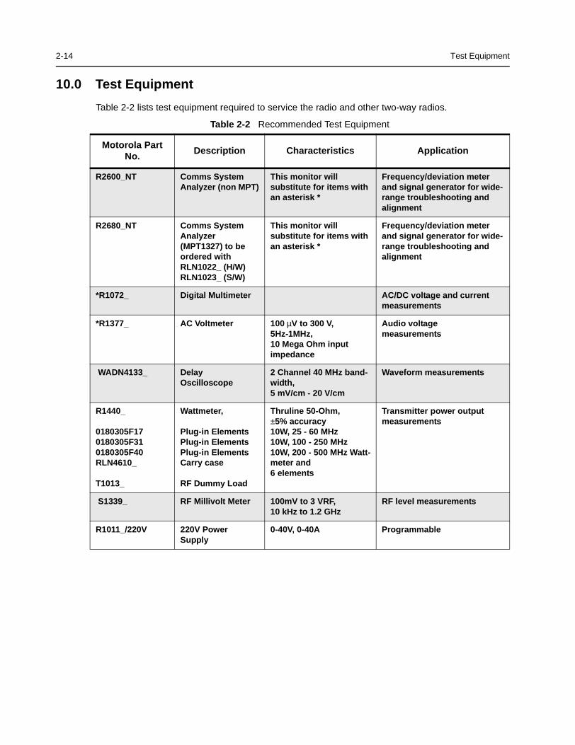
10.0 Test Equipment
Table 2-2 lists test equipment required to service the radio and other two-way radios.
Table 2-2 Recommended Test Equipment
Motorola PartNo.
Description Characteristics Application
R2600_NT Comms SystemAnalyzer (non MPT)
This monitor willsubstitute for items withan asterisk *
Frequency/deviation meterand signal generator for wide-range troubleshooting andalignment
R2680_NT Comms SystemAnalyzer(MPT1327) to beordered withRLN1022_ (H/W)RLN1023_ (S/W)
This monitor willsubstitute for items withan asterisk *
Frequency/deviation meterand signal generator for wide-range troubleshooting andalignment
*R1072_ Digital Multimeter AC/DC voltage and currentmeasurements
*R1377_ AC Voltmeter 100 µV to 300 V,5Hz-1MHz,10 Mega Ohm inputimpedance
Audio voltagemeasurements
WADN4133_ DelayOscilloscope
2 Channel 40 MHz band-width,5 mV/cm - 20 V/cm
Waveform measurements
R1440_
0180305F170180305F310180305F40RLN4610_
T1013_
Wattmeter,
Plug-in ElementsPlug-in ElementsPlug-in ElementsCarry case
RF Dummy Load
Thruline 50-Ohm,±5% accuracy10W, 25 - 60 MHz10W, 100 - 250 MHz10W, 200 - 500 MHz Watt-meter and6 elements
Transmitter power outputmeasurements
S1339_ RF Millivolt Meter 100mV to 3 VRF,10 kHz to 1.2 GHz
RF level measurements
R1011_/220V 220V PowerSupply
0-40V, 0-40A Programmable
Programming/Test Cable - RKN4083_ 2-15
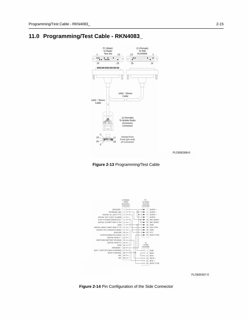
11.0 Programming/Test Cable - RKN4083_
Figure 2-13 Programming/Test Cable
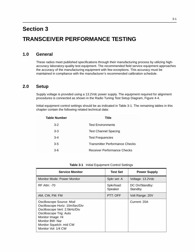
Figure 2-14 Pin Configuration of the Side Connector
P1 (Male)To Radio Test Set
J2 (Female)To Mobile Radio
AccessoryConnector
1 13 13 1
14252514
J1 (Female)To RIB
RLN4008
FL0830308O
1000 50mmCable
+_
1000 50mmCable
+_
17
18
1
2
19
20
Viewed fromFront (pin end)of Connector
FLO830308-0
J2 Mobile Radio
Accessory Connector
SPEAKER -
EXTERNAL MIC
DIGITAL IN 1 (EXT. PTT)
DIGITAL OUT 2 (EXT. ALARM)
FLAT TX AUDIO SENSITIVITY
DIGITAL IN 3/MPT MAP 27 RX
GND
DIGITAL IN/OUT 4/MPT MAP 27 TX
DIGITAL IN 5 w WAKEUP (EMG)
IGNITION
FLAT/FILTERED RX AUDIO
DIGITAL IN/OUT 7
SWITCHED BATTERY VOLTAGE
DIGITAL IN/OUT 8
RSSI
SPEAKER +
BUS + (FOR CPS AND FLASHING)
BOOT CONTROL
N/C
N/C
1
2
3
4
5
6
7
8
9
10
11
12
13
14
15
16
17
18
19
20
AUDIO +
AUDIO -
AUDIO +
AUDIO -
MIC AUDIO
MIC AUDIO
GND
VOL CTRL
DISC
PTT
BOOT CTRL
1
2
5
7
10
15
16
18
19
20
25
P1 To RadioTest Set
RLN4460
GND
BIAS
BUS -
SW B +
BUS +
BOOT CTRL
1
4
11
12
15
25
J1To RIB
RLN4008
FL0830307O
FLO830307-0

2-16 Programming/Test Cable - RKN4083_
THIS PAGE INTENTIONALLY LEFT BLANK
3-1
Section 3
TRANSCEIVER PERFORMANCE TESTING
1.0 General
These radios meet published specifications through their manufacturing process by utilizing high-accuracy laboratory-quality test equipment. The recommended field service equipment approachesthe accuracy of the manufacturing equipment with few exceptions. This accuracy must bemaintained in compliance with the manufacturer’s recommended calibration schedule.
2.0 Setup
Supply voltage is provided using a 13.2Vdc power supply. The equipment required for alignmentprocedures is connected as shown in the Radio Tuning Test Setup Diagram, Figure 4-4.
Initial equipment control settings should be as indicated in Table 3-1. The remaining tables in thischapter contain the following related technical data:
Table Number Title
3-2 Test Environments
3-3 Test Channel Spacing
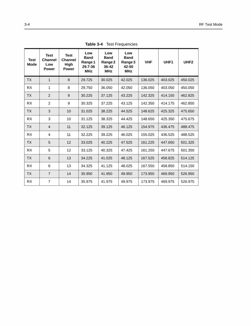
3-4 Test Frequencies
3-5 Transmitter Performance Checks
3-6 Receiver Performance Checks
Table 3-1 Initial Equipment Control Settings
Service Monitor Test Set Power Supply
Monitor Mode: Power Monitor Spkr set: A Voltage: 13.2Vdc
RF Attn: -70 Spkr/load:Speaker
DC On/Standby:Standby
AM, CW, FM: FM PTT: OFF Volt Range: 20V
Oscilloscope Source: ModOscilloscope Horiz: 10mSec/DivOscilloscope Vert: 2.5kHz/DivOscilloscope Trig: AutoMonitor Image: HiMonitor BW: NarMonitor Squelch: mid CWMonitor Vol: 1/4 CW
Current: 20A
3-2 RF Test Mode
3.0 RF Test Mode
When the radio is operating in its normal environment, the radio’s microcontroller controls the RFchannel selection, transmitter key-up, and receiver muting. However, when the unit is on the benchfor testing, alignment, or repair, it is removed from its normal environment and cannot receivecommands from its system. Therefore, the internal microcontroller does not key the transmitter orunmute the receiver. This prevents the use of a normal tuning procedure. To solve this problem, aspecial “test mode” is incorporated into the radio.
To enter test mode (display radios):
1. Turn the radio on.
2. Within ten seconds after the self test is complete, press button P2, five times in succession.
3. After “CSQ CHXX SP25” appears in the display, the radio is on channel XX, carrier squelchmode, 25 kHz channel spacing.
4. Each additional press of P2 scrolls through to the next channel spacing and a correspondingset of tones are sounded.
5. Pressing P1 scrolls through and accesses test environments as shown in 3-2.
6. Pressing P2 for three seconds switches the radio to the control head test mode. ‘LCD Test ’appears on the display.
7. Pressing P1 causes the radio to turn on all the dots of the first character. Another P1 pressturns on all the dots of the next character and so on until the last character.
8. Pressing P1 at the end of the LCD test activates the ‘Icon Test’. The next P1 press turns onthe first icon.
9. Pressing P1 at the end of the Icon test activates the “Button Test” mode. Pressing any button(except P1) or any keypad button during the LCD test or Icon test immediately activates thistest.
10. Pressing P2 for 3 seconds in the control head test mode causes the radio to return to the RFtest mode.
RF Test Mode 3-3
Table 3-2 Test Environments
No. ofBeeps
Description Function
1(highpitch)
Carrier Squelch(CSQ)
RX: unsquelch if carrier detectedTX: mic audio
1 TonePrivate-Line (TPL)
RX: unsquelch if carrier and tone (192.8Hz) detectedTX: mic audio + tone (192.8Hz)
2 DigitalPrivate-Line (DPL)
RX: unsquelch if carrier and digital code (131) detectedTX: mic audio + digital code (131)
3 Dual-Tone mul-tiple frequency(DTMF)
RX: unsquelch if carrier detectedTX: selected DTMF tone pair
5 Unsquelch(Open)
RX: constant unsquelchTX: mic audio
9 MDC1200(HSS)
RX: unsquelch if carrier detectedTX: 1500 Hz tone
11 CMP RX: unsquelch if carrier detectedTX: mic audio
12 LLE RX: unsquelch if carrier detectedTX: mic audio
Table 3-3 Test Channel Spacing
Number of Beeps Channel Spacing
1 25 kHz
2 12.5 kHz
3 20 kHz
3-4 RF Test Mode
Table 3-4 Test Frequencies
TestMode
TestChannel
LowPower
TestChannel
HighPower
LowBand
Range 129.7-36
MHz
LowBand
Range 236-42MHz
LowBand
Range 342-50MHz
VHF UHF1 UHF2
TX 1 8 29.725 30.025 42.025 136.025 403.025 450.025
RX 1 8 29.750 36.050 42.050 136.050 403.050 450.050
TX 2 9 30.225 37.125 43.225 142.325 414.150 462.825
RX 2 9 30.325 37.225 43.125 142.350 414.175 462.850
TX 3 10 31.025 38.225 44.525 148.625 425.325 475.650
RX 3 10 31.125 38.325 44.425 148.650 425.350 475.675
TX 4 11 32.125 39.125 46.125 154.975 436.475 488.475
RX 4 11 32.225 39.225 46.025 155.025 436.525 488.525
TX 5 12 33.025 40.225 47.525 161.225 447.650 501.325
RX 5 12 33.125 40.325 47.425 161.250 447.675 501.350
TX 6 13 34.225 41.025 48.125 167.525 458.825 514.125
RX 6 13 34.325 41.125 48.025 167.550 458.850 514.150
TX 7 14 35.950 41.950 49.950 173.950 469.950 526.950
RX 7 14 35.975 41.975 49.975 173.975 469.975 526.975
RF Test Mode 3-5
* See 3-4** MPT
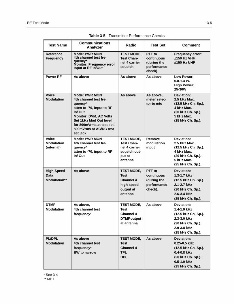
Table 3-5 Transmitter Performance Checks
Test Name CommunicationsAnalyzer Radio Test Set Comment
ReferenceFrequency
Mode: PWR MON4th channel test fre-quency*Monitor: Frequency errorInput at RF In/Out
TEST MODE,Test Chan-nel 4 carriersquelch
PTT tocontinuous(during theperformancecheck)
Frequency error:±150 Hz VHF,±150 Hz UHF
Power RF As above As above As above Low Power:0.8-1.4 W.High Power:25-30W
VoiceModulation
Mode: PWR MON4th channel test fre-quency*atten to -70, input to RFIn/ OutMonitor: DVM, AC VoltsSet 1kHz Mod Out levelfor 800mVrms at test set,800mVrms at AC/DC testset jack
As above As above,meter selec-tor to mic
Deviation:2.5 kHz Max.(12.5 kHz Ch. Sp.).4 kHz Max.(20 kHz Ch. Sp.).5 kHz Max.(25 kHz Ch. Sp.).
VoiceModulation(internal)
Mode: PWR MON4th channel test fre-quency*atten to -70, input to RFIn/ Out
TEST MODE,Test Chan-nel 4 carriersquelch out-put atantenna
Removemodulationinput
Deviation:2.5 kHz Max.(12.5 kHz Ch. Sp.).4 kHz Max.(20 kHz Ch. Sp.).5 kHz Max.(25 kHz Ch. Sp.).
High-SpeedDataModulation**
As above TEST MODE,TestChannel 4high speedoutput atantenna
PTT tocontinuous(during theperformancecheck).
Deviation:1.3-1.7 kHz(12.5 kHz Ch. Sp.).2.1-2.7 kHz(20 kHz Ch. Sp.).2.6-3.4 kHz(25 kHz Ch. Sp.).
DTMFModulation
As above,4th channel testfrequency*
TEST MODE,TestChannel 4DTMF outputat antenna
As above Deviation:1.4-1.9 kHz(12.5 kHz Ch. Sp.).2.3-3.0 kHz(20 kHz Ch. Sp.).2.9-3.8 kHz(25 kHz Ch. Sp.).
PL/DPLModulation
As above4th channel testfrequency*BW to narrow
TEST MODE,TestChannel 4TPLDPL
As above Deviation:0.25-0.5 kHz(12.5 kHz Ch. Sp.).0.4-0.8 kHz(20 kHz Ch. Sp.).0.5-1.0 kHz(25 kHz Ch. Sp.).
3-6 RF Test Mode
* See 3-4
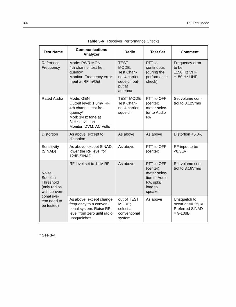
Table 3-6 Receiver Performance Checks
Test NameCommunications
AnalyzerRadio Test Set Comment
ReferenceFrequency
Mode: PWR MON4th channel test fre-quency*Monitor: Frequency errorInput at RF In/Out
TESTMODE,Test Chan-nel 4 carriersquelch out-put atantenna
PTT tocontinuous(during theperformancecheck)
Frequency errorto be±150 Hz VHF±150 Hz UHF
Rated Audio Mode: GENOutput level: 1.0mV RF4th channel test fre-quency*Mod: 1kHz tone at3kHz deviationMonitor: DVM: AC Volts
TEST MODETest Chan-nel 4 carriersquelch
PTT to OFF(center),meter selec-tor to AudioPA
Set volume con-trol to 8.12Vrms
Distortion As above, except todistortion
As above As above Distortion <5.0%
Sensitivity(SINAD)
As above, except SINAD,lower the RF level for12dB SINAD.
As above PTT to OFF(center)
RF input to be<0.3µV
NoiseSquelchThreshold(only radioswith conven-tional sys-tem need tobe tested)
RF level set to 1mV RF As above PTT to OFF(center),meter selec-tion to AudioPA, spkr/load tospeaker
Set volume con-trol to 3.16Vrms
As above, except changefrequency to a conven-tional system. Raise RFlevel from zero until radiounsquelches.
out of TESTMODE;select aconventionalsystem
As above Unsquelch tooccur at <0.25µV.Preferred SINAD= 9-10dB
4-1
Section 4
RADIO TUNING AND PROGRAMMING
1.0 Introduction
This chapter provides an overview of the Customer Programming Software (CPS) and tunerprogram which are designed for use in a Windows 95/98 environment. These programs areavailable in separate kits as listed in the Table 4-1. An Installation instruction manual is alsoincluded with each kit.
Table 4-1 Software Installation Kits Radio Tuning Setup
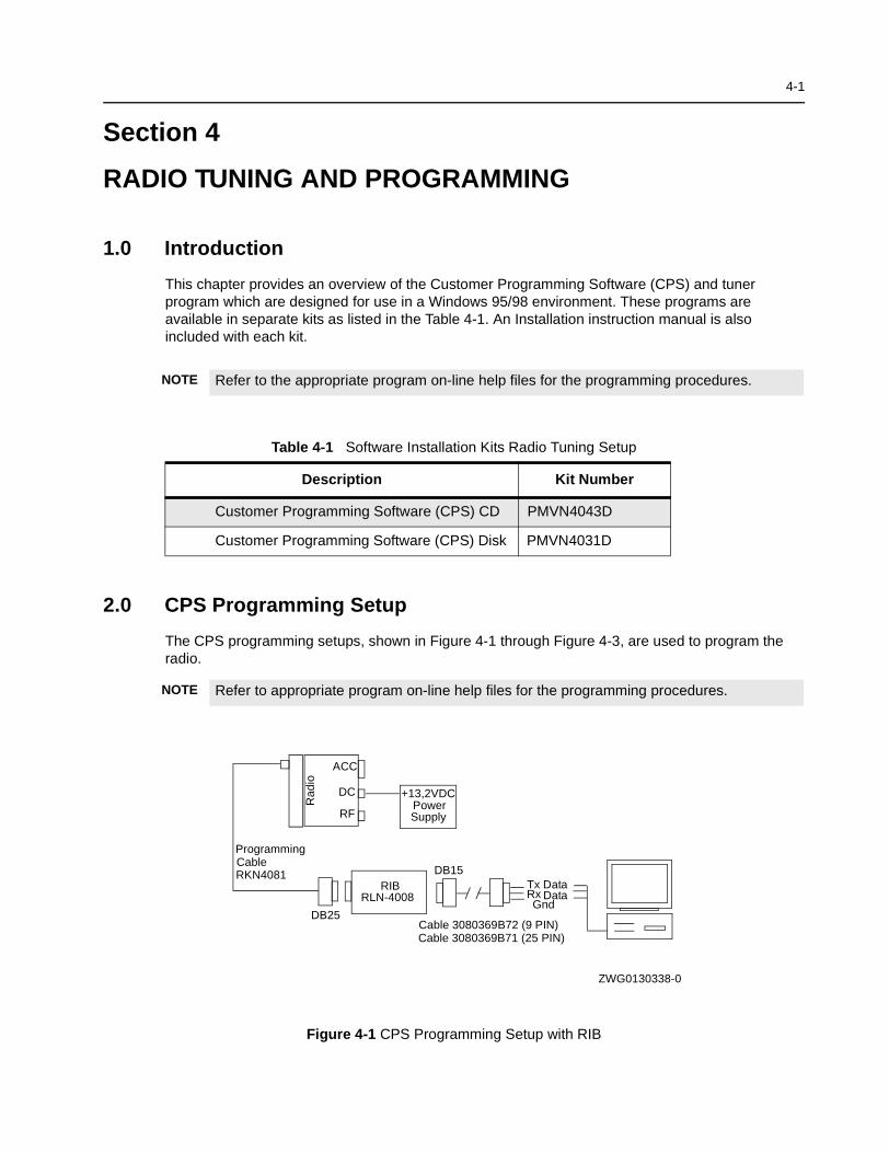
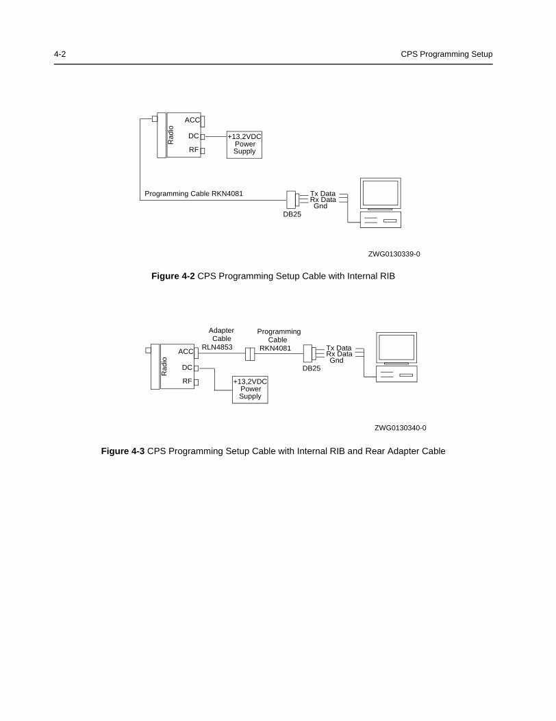
2.0 CPS Programming Setup
The CPS programming setups, shown in Figure 4-1 through Figure 4-3, are used to program theradio.
NOTE Refer to the appropriate program on-line help files for the programming procedures.
Description Kit Number
Customer Programming Software (CPS) CD PMVN4043D
Customer Programming Software (CPS) Disk PMVN4031D
NOTE Refer to appropriate program on-line help files for the programming procedures.
Figure 4-1 CPS Programming Setup with RIB
RIBRLN-4008 Rx
GndData
Tx Data
Cable 3080369B72 (9 PIN)
DB15
Cable 3080369B71 (25 PIN)
PowerSupply
+13,2VDC
Programming
RKN4081Cable
DB25
Rad
io
DC
RF
ACC
ZWG0130338-0
4-2 CPS Programming Setup
Figure 4-2 CPS Programming Setup Cable with Internal RIB
Figure 4-3 CPS Programming Setup Cable with Internal RIB and Rear Adapter Cable
PowerSupply
+13,2VDC
Programming Cable RKN4081Rx DataGnd
Tx Data
DB25
Rad
io
DC
RF
ACC
ZWG0130339-0
Programming
RKN4081Cable
Adapter
RLN4853Cable
Rx DataGnd
Tx Data
DB25
Rad
io
DC
RF
ACC
PowerSupply
+13,2VDC
ZWG0130340-0
Radio Tuning Setup 4-3
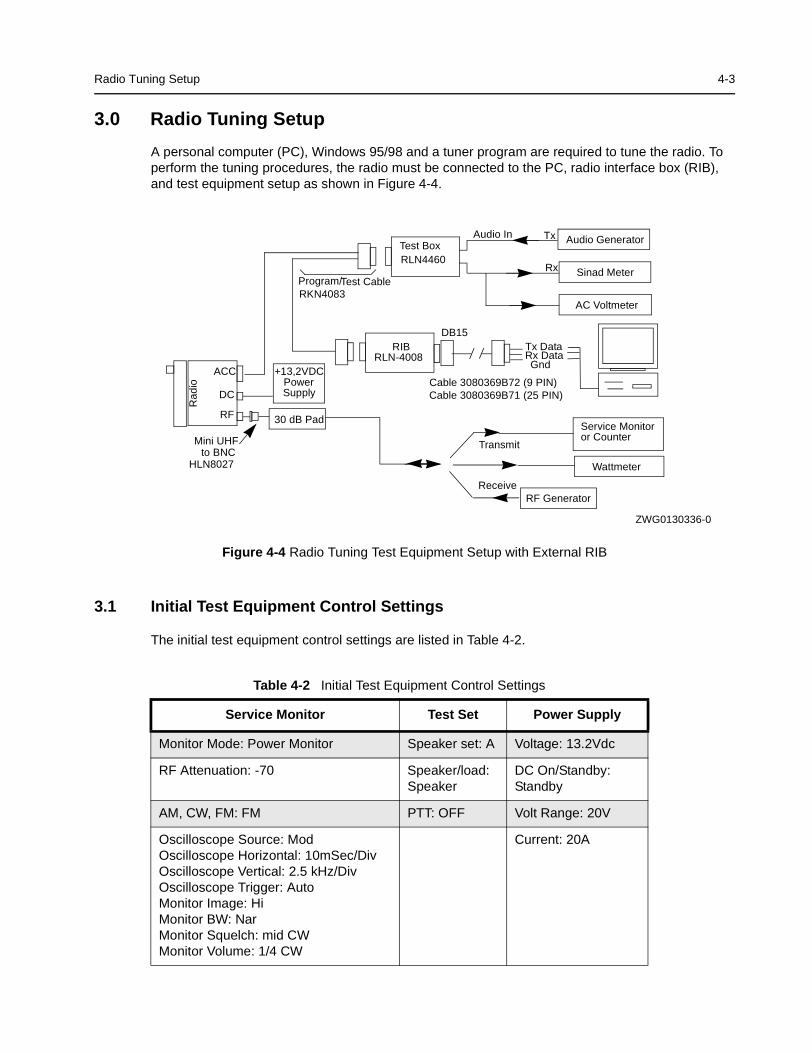
3.0 Radio Tuning Setup
A personal computer (PC), Windows 95/98 and a tuner program are required to tune the radio. Toperform the tuning procedures, the radio must be connected to the PC, radio interface box (RIB),and test equipment setup as shown in Figure 4-4.
Figure 4-4 Radio Tuning Test Equipment Setup with External RIB
3.1 Initial Test Equipment Control Settings
The initial test equipment control settings are listed in Table 4-2.
Table 4-2 Initial Test Equipment Control Settings
Service Monitor Test Set Power Supply
Monitor Mode: Power Monitor Speaker set: A Voltage: 13.2Vdc
RF Attenuation: -70 Speaker/load:Speaker
DC On/Standby:Standby
AM, CW, FM: FM PTT: OFF Volt Range: 20V
Oscilloscope Source: ModOscilloscope Horizontal: 10mSec/DivOscilloscope Vertical: 2.5 kHz/DivOscilloscope Trigger: AutoMonitor Image: HiMonitor BW: NarMonitor Squelch: mid CWMonitor Volume: 1/4 CW
Current: 20A
Wattmeter
Audio Generator
Sinad Meter
AC Voltmeter
30 dB Pad
Audio In Tx
Rx
Receive
Transmit
RF Generator
RIBRLN-4008
RLN4460Test Box
Cable 3080369B72 (9 PIN)
Program/RKN4083
Test Cable
Service Monitoror Counter
DB15
HLN8027
Mini UHF
Cable 3080369B71 (25 PIN)PowerSupply
+13,2VDC
Rx DataGnd
Tx Data
to BNC
Rad
io
DC
RF
ACC
ZWG0130336-0

4-4 Radio Tuning Setup
THIS PAGE INTENTIONALLY LEFT BLANK
5-1
Section 5
POWER UP SELF-TEST
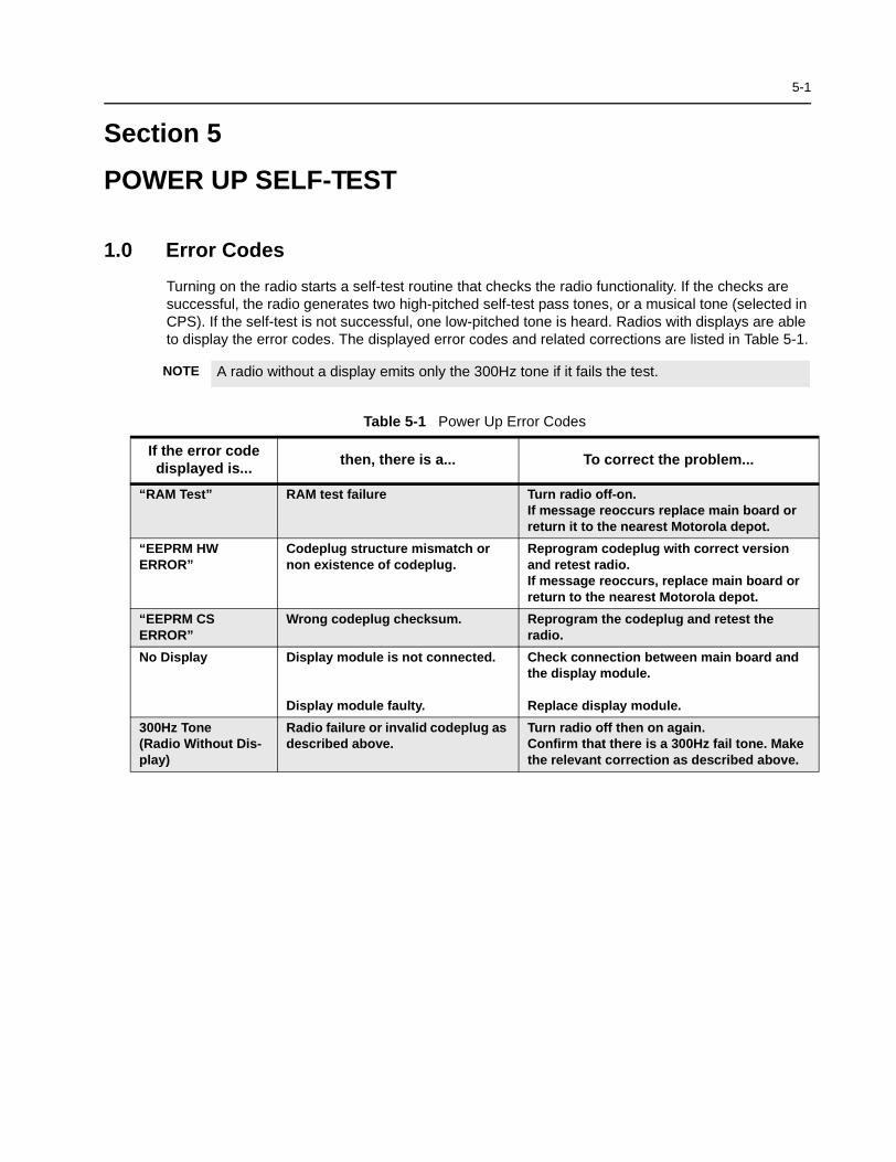
1.0 Error Codes
Turning on the radio starts a self-test routine that checks the radio functionality. If the checks aresuccessful, the radio generates two high-pitched self-test pass tones, or a musical tone (selected inCPS). If the self-test is not successful, one low-pitched tone is heard. Radios with displays are ableto display the error codes. The displayed error codes and related corrections are listed in Table 5-1.
NOTE A radio without a display emits only the 300Hz tone if it fails the test.
Table 5-1 Power Up Error Codes
If the error codedisplayed is...
then, there is a... To correct the problem...
“RAM Test” RAM test failure Turn radio off-on.If message reoccurs replace main board orreturn it to the nearest Motorola depot.
“EEPRM HWERROR”
Codeplug structure mismatch ornon existence of codeplug.
Reprogram codeplug with correct versionand retest radio.If message reoccurs, replace main board orreturn to the nearest Motorola depot.
“EEPRM CSERROR”
Wrong codeplug checksum. Reprogram the codeplug and retest theradio.
No Display Display module is not connected.
Display module faulty.
Check connection between main board andthe display module.
Replace display module.
300Hz Tone(Radio Without Dis-play)
Radio failure or invalid codeplug asdescribed above.
Turn radio off then on again.Confirm that there is a 300Hz fail tone. Makethe relevant correction as described above.

5-2 Error Codes
THIS PAGE INTENTIONALLY LEFT BLANK
6-1
Section 6
MODEL CHART AND TEST SPECIFICATION
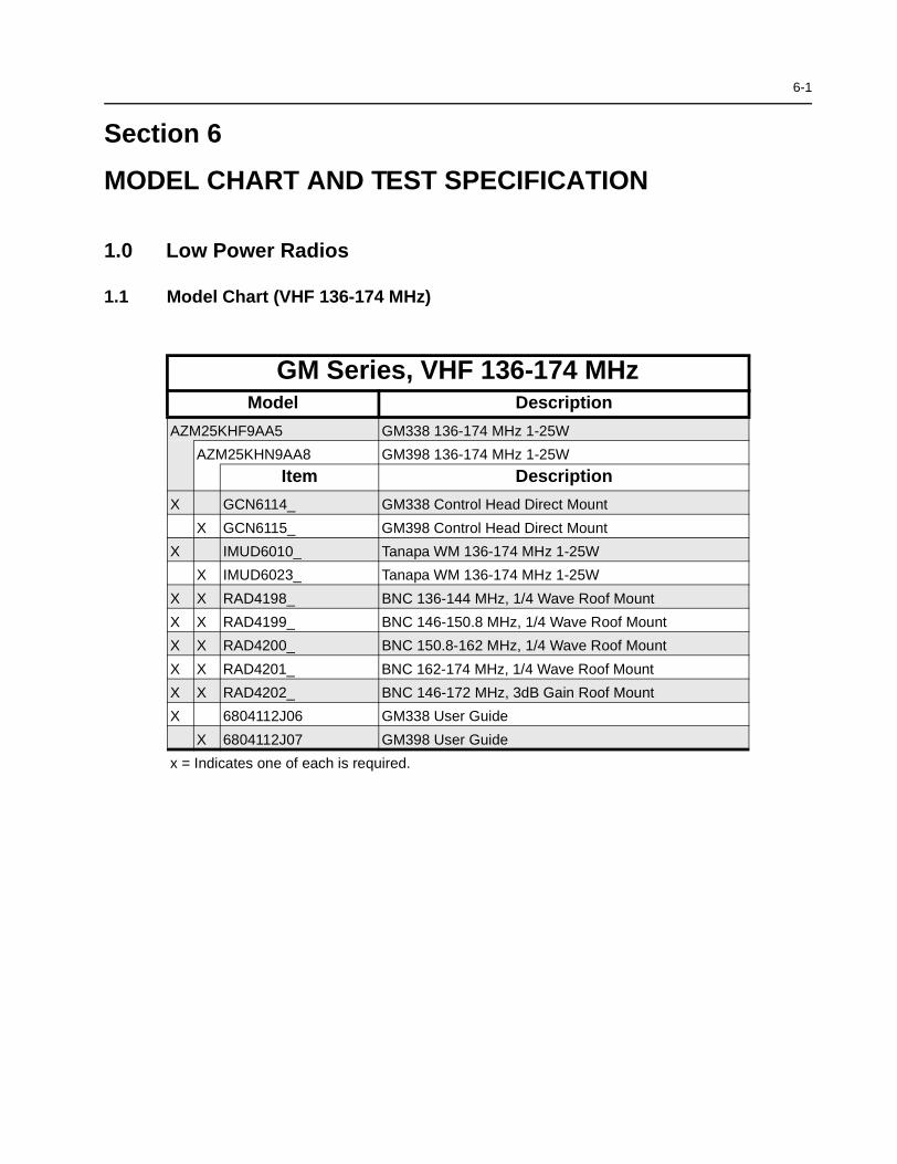
1.0 Low Power Radios
1.1 Model Chart (VHF 136-174 MHz)
GM Series, VHF 136-174 MHzModel Description
AZM25KHF9AA5 GM338 136-174 MHz 1-25W
AZM25KHN9AA8 GM398 136-174 MHz 1-25W
Item Description
X GCN6114_ GM338 Control Head Direct Mount
X GCN6115_ GM398 Control Head Direct Mount
X IMUD6010_ Tanapa WM 136-174 MHz 1-25W
X IMUD6023_ Tanapa WM 136-174 MHz 1-25W
X X RAD4198_ BNC 136-144 MHz, 1/4 Wave Roof Mount
X X RAD4199_ BNC 146-150.8 MHz, 1/4 Wave Roof Mount
X X RAD4200_ BNC 150.8-162 MHz, 1/4 Wave Roof Mount
X X RAD4201_ BNC 162-174 MHz, 1/4 Wave Roof Mount
X X RAD4202_ BNC 146-172 MHz, 3dB Gain Roof Mount
X 6804112J06 GM338 User Guide
X 6804112J07 GM398 User Guide
x = Indicates one of each is required.
6-2 Low Power Radios
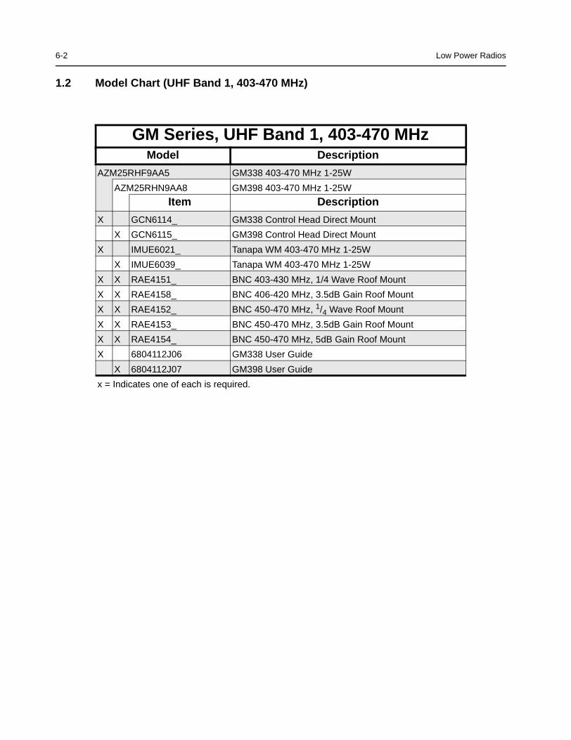
1.2 Model Chart (UHF Band 1, 403-470 MHz)
GM Series, UHF Band 1, 403-470 MHzModel Description
AZM25RHF9AA5 GM338 403-470 MHz 1-25W
AZM25RHN9AA8 GM398 403-470 MHz 1-25W
Item Description
X GCN6114_ GM338 Control Head Direct Mount
X GCN6115_ GM398 Control Head Direct Mount
X IMUE6021_ Tanapa WM 403-470 MHz 1-25W
X IMUE6039_ Tanapa WM 403-470 MHz 1-25W
X X RAE4151_ BNC 403-430 MHz, 1/4 Wave Roof Mount
X X RAE4158_ BNC 406-420 MHz, 3.5dB Gain Roof Mount
X X RAE4152_ BNC 450-470 MHz, 1/4 Wave Roof Mount
X X RAE4153_ BNC 450-470 MHz, 3.5dB Gain Roof Mount
X X RAE4154_ BNC 450-470 MHz, 5dB Gain Roof Mount
X 6804112J06 GM338 User Guide
X 6804112J07 GM398 User Guide
x = Indicates one of each is required.
Low Power Radios 6-3
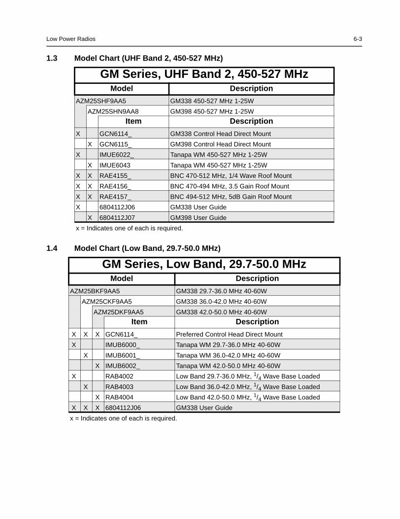
1.3 Model Chart (UHF Band 2, 450-527 MHz)
1.4 Model Chart (Low Band, 29.7-50.0 MHz)
GM Series, UHF Band 2, 450-527 MHzModel Description
AZM25SHF9AA5 GM338 450-527 MHz 1-25W
AZM25SHN9AA8 GM398 450-527 MHz 1-25W
Item Description
X GCN6114_ GM338 Control Head Direct Mount
X GCN6115_ GM398 Control Head Direct Mount
X IMUE6022_ Tanapa WM 450-527 MHz 1-25W
X IMUE6043 Tanapa WM 450-527 MHz 1-25W
X X RAE4155_ BNC 470-512 MHz, 1/4 Wave Roof Mount
X X RAE4156_ BNC 470-494 MHz, 3.5 Gain Roof Mount
X X RAE4157_ BNC 494-512 MHz, 5dB Gain Roof Mount
X 6804112J06 GM338 User Guide
X 6804112J07 GM398 User Guide
x = Indicates one of each is required.
GM Series, Low Band, 29.7-50.0 MHzModel Description
AZM25BKF9AA5 GM338 29.7-36.0 MHz 40-60W
AZM25CKF9AA5 GM338 36.0-42.0 MHz 40-60W
AZM25DKF9AA5 GM338 42.0-50.0 MHz 40-60W
Item Description
X X X GCN6114_ Preferred Control Head Direct Mount
X IMUB6000_ Tanapa WM 29.7-36.0 MHz 40-60W
X IMUB6001_ Tanapa WM 36.0-42.0 MHz 40-60W
X IMUB6002_ Tanapa WM 42.0-50.0 MHz 40-60W
X RAB4002 Low Band 29.7-36.0 MHz, 1/4 Wave Base Loaded
X RAB4003 Low Band 36.0-42.0 MHz, 1/4 Wave Base Loaded
X RAB4004 Low Band 42.0-50.0 MHz, 1/4 Wave Base Loaded
X X X 6804112J06 GM338 User Guide
x = Indicates one of each is required.
6-4 Low Power Radios
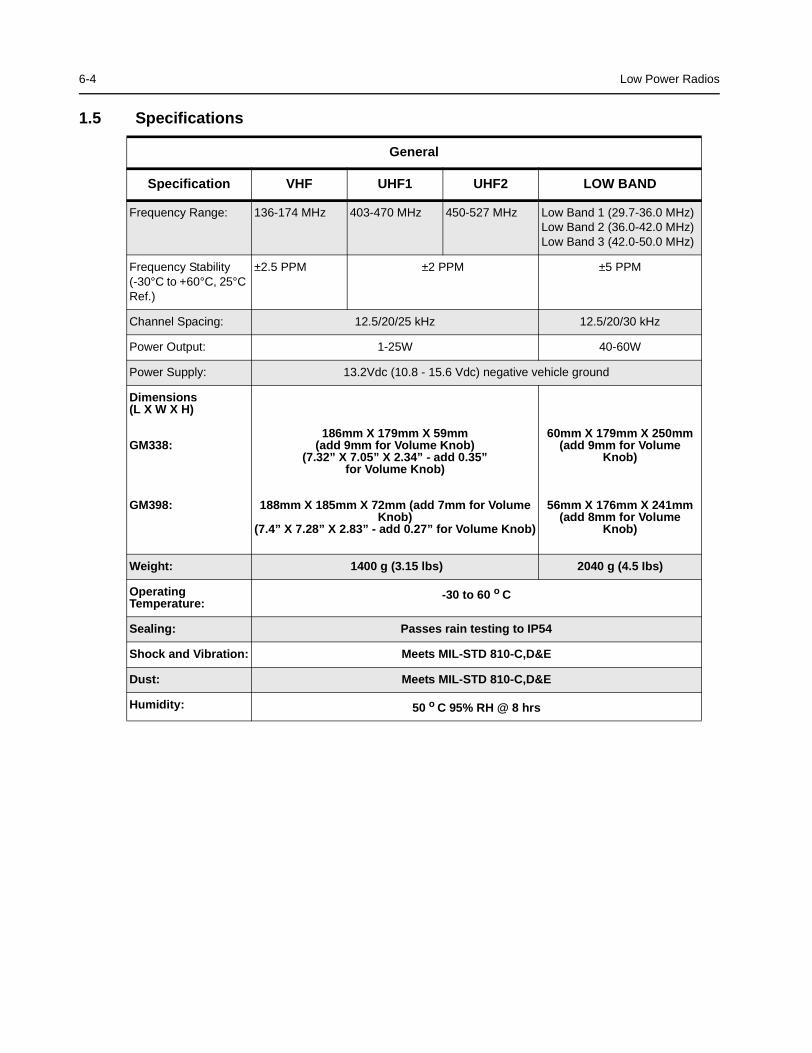
1.5 Specifications
General
Specification VHF UHF1 UHF2 LOW BAND
Frequency Range: 136-174 MHz 403-470 MHz 450-527 MHz Low Band 1 (29.7-36.0 MHz)Low Band 2 (36.0-42.0 MHz)Low Band 3 (42.0-50.0 MHz)
Frequency Stability(-30°C to +60°C, 25°CRef.)
±2.5 PPM ±2 PPM ±5 PPM
Channel Spacing: 12.5/20/25 kHz 12.5/20/30 kHz
Power Output: 1-25W 40-60W
Power Supply: 13.2Vdc (10.8 - 15.6 Vdc) negative vehicle ground
Dimensions(L X W X H)
GM338:
GM398:
186mm X 179mm X 59mm(add 9mm for Volume Knob)
(7.32” X 7.05” X 2.34” - add 0.35”for Volume Knob)
188mm X 185mm X 72mm (add 7mm for VolumeKnob)
(7.4” X 7.28” X 2.83” - add 0.27” for Volume Knob)
60mm X 179mm X 250mm(add 9mm for Volume
Knob)
56mm X 176mm X 241mm(add 8mm for Volume
Knob)
Weight: 1400 g (3.15 lbs) 2040 g (4.5 Ibs)
OperatingTemperature:
-30 to 60 o C
Sealing: Passes rain testing to IP54
Shock and Vibration: Meets MIL-STD 810-C,D&E
Dust: Meets MIL-STD 810-C,D&E
Humidity: 50 o C 95% RH @ 8 hrs
Low Power Radios 6-5
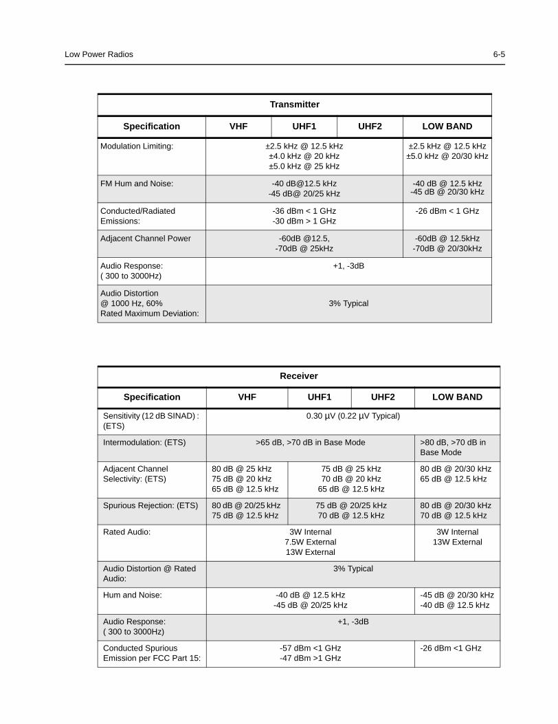
Transmitter
Specification VHF UHF1 UHF2 LOW BAND
Modulation Limiting: ±2.5 kHz @ 12.5 kHz±4.0 kHz @ 20 kHz±5.0 kHz @ 25 kHz
±2.5 kHz @ 12.5 kHz±5.0 kHz @ 20/30 kHz
FM Hum and Noise: -40 [email protected] kHz-45 dB@ 20/25 kHz
-40 dB @ 12.5 kHz-45 dB @ 20/30 kHz
Conducted/RadiatedEmissions:
-36 dBm < 1 GHz-30 dBm > 1 GHz
-26 dBm < 1 GHz
Adjacent Channel Power -60dB @12.5,-70dB @ 25kHz
-60dB @ 12.5kHz-70dB @ 20/30kHz
Audio Response:( 300 to 3000Hz)
+1, -3dB
Audio Distortion@ 1000 Hz, 60%Rated Maximum Deviation:
3% Typical
Receiver
Specification VHF UHF1 UHF2 LOW BAND
Sensitivity (12 dB SINAD) :(ETS)
0.30 µV (0.22 µV Typical)
Intermodulation: (ETS) >65 dB, >70 dB in Base Mode >80 dB, >70 dB inBase Mode
Adjacent ChannelSelectivity: (ETS)
80 dB @ 25 kHz75 dB @ 20 kHz65 dB @ 12.5 kHz
75 dB @ 25 kHz70 dB @ 20 kHz
65 dB @ 12.5 kHz
80 dB @ 20/30 kHz65 dB @ 12.5 kHz
Spurious Rejection: (ETS) 80 dB @ 20/25 kHz75 dB @ 12.5 kHz
75 dB @ 20/25 kHz70 dB @ 12.5 kHz
80 dB @ 20/30 kHz70 dB @ 12.5 kHz
Rated Audio: 3W Internal7.5W External13W External
3W Internal13W External
Audio Distortion @ RatedAudio:
3% Typical
Hum and Noise: -40 dB @ 12.5 kHz-45 dB @ 20/25 kHz
-45 dB @ 20/30 kHz-40 dB @ 12.5 kHz
Audio Response:( 300 to 3000Hz)
+1, -3dB
Conducted SpuriousEmission per FCC Part 15:
-57 dBm <1 GHz-47 dBm >1 GHz
-26 dBm <1 GHz
6-6 High Power Radios
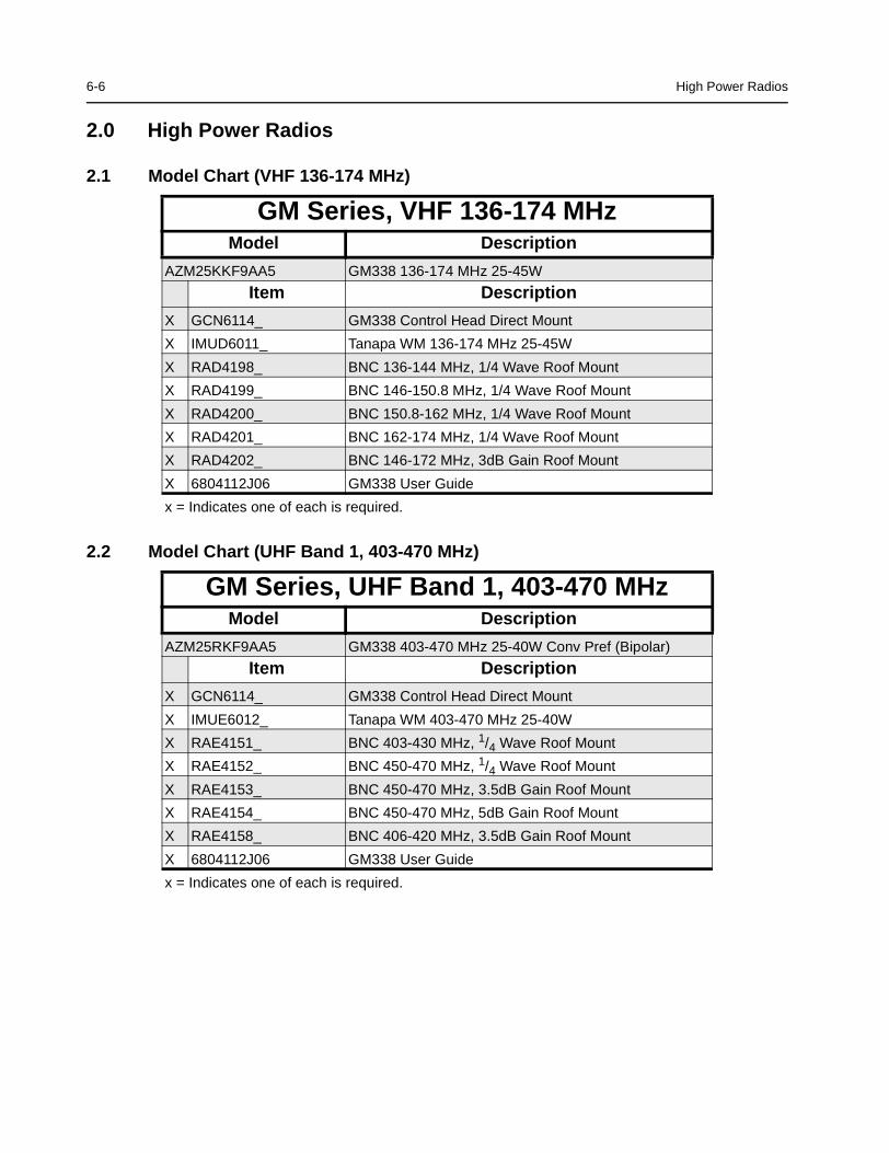
2.0 High Power Radios
2.1 Model Chart (VHF 136-174 MHz)
2.2 Model Chart (UHF Band 1, 403-470 MHz)
GM Series, VHF 136-174 MHzModel Description
AZM25KKF9AA5 GM338 136-174 MHz 25-45W
Item Description
X GCN6114_ GM338 Control Head Direct Mount
X IMUD6011_ Tanapa WM 136-174 MHz 25-45W
X RAD4198_ BNC 136-144 MHz, 1/4 Wave Roof Mount
X RAD4199_ BNC 146-150.8 MHz, 1/4 Wave Roof Mount
X RAD4200_ BNC 150.8-162 MHz, 1/4 Wave Roof Mount
X RAD4201_ BNC 162-174 MHz, 1/4 Wave Roof Mount
X RAD4202_ BNC 146-172 MHz, 3dB Gain Roof Mount
X 6804112J06 GM338 User Guide
x = Indicates one of each is required.
GM Series, UHF Band 1, 403-470 MHzModel Description
AZM25RKF9AA5 GM338 403-470 MHz 25-40W Conv Pref (Bipolar)
Item Description
X GCN6114_ GM338 Control Head Direct Mount
X IMUE6012_ Tanapa WM 403-470 MHz 25-40W
X RAE4151_ BNC 403-430 MHz, 1/4 Wave Roof Mount
X RAE4152_ BNC 450-470 MHz, 1/4 Wave Roof Mount
X RAE4153_ BNC 450-470 MHz, 3.5dB Gain Roof Mount
X RAE4154_ BNC 450-470 MHz, 5dB Gain Roof Mount
X RAE4158_ BNC 406-420 MHz, 3.5dB Gain Roof Mount
X 6804112J06 GM338 User Guide
x = Indicates one of each is required.
High Power Radios 6-7
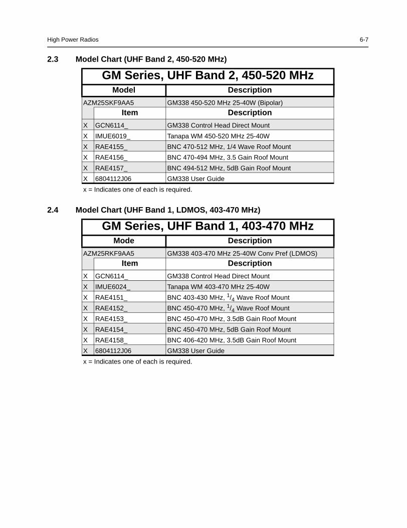
2.3 Model Chart (UHF Band 2, 450-520 MHz)
2.4 Model Chart (UHF Band 1, LDMOS, 403-470 MHz)
GM Series, UHF Band 2, 450-520 MHzModel Description
AZM25SKF9AA5 GM338 450-520 MHz 25-40W (Bipolar)
Item Description
X GCN6114_ GM338 Control Head Direct Mount
X IMUE6019_ Tanapa WM 450-520 MHz 25-40W
X RAE4155_ BNC 470-512 MHz, 1/4 Wave Roof Mount
X RAE4156_ BNC 470-494 MHz, 3.5 Gain Roof Mount
X RAE4157_ BNC 494-512 MHz, 5dB Gain Roof Mount
X 6804112J06 GM338 User Guide
x = Indicates one of each is required.
GM Series, UHF Band 1, 403-470 MHzMode Description
AZM25RKF9AA5 GM338 403-470 MHz 25-40W Conv Pref (LDMOS)
Item Description
X GCN6114_ GM338 Control Head Direct Mount
X IMUE6024_ Tanapa WM 403-470 MHz 25-40W
X RAE4151_ BNC 403-430 MHz, 1/4 Wave Roof Mount
X RAE4152_ BNC 450-470 MHz, 1/4 Wave Roof Mount
X RAE4153_ BNC 450-470 MHz, 3.5dB Gain Roof Mount
X RAE4154_ BNC 450-470 MHz, 5dB Gain Roof Mount
X RAE4158_ BNC 406-420 MHz, 3.5dB Gain Roof Mount
X 6804112J06 GM338 User Guide
x = Indicates one of each is required.
6-8 High Power Radios
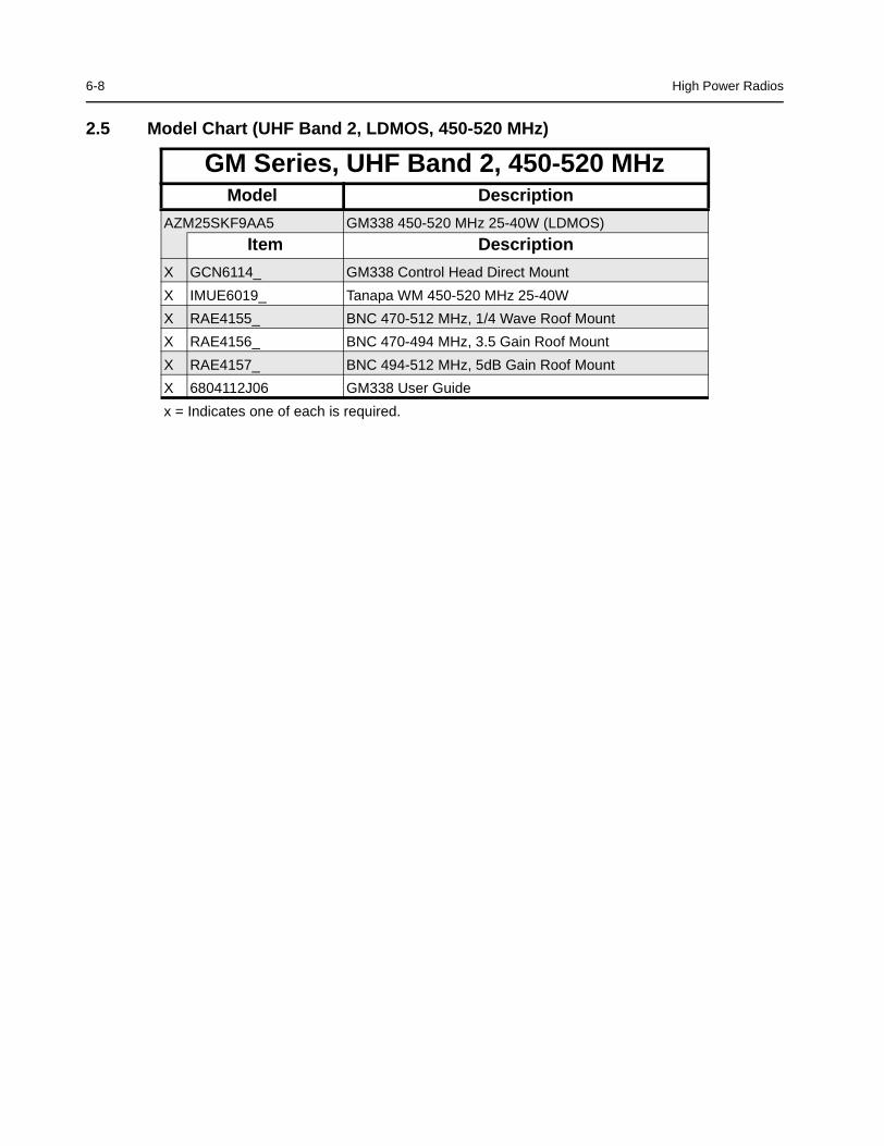
2.5 Model Chart (UHF Band 2, LDMOS, 450-520 MHz)
GM Series, UHF Band 2, 450-520 MHzModel Description
AZM25SKF9AA5 GM338 450-520 MHz 25-40W (LDMOS)
Item Description
X GCN6114_ GM338 Control Head Direct Mount
X IMUE6019_ Tanapa WM 450-520 MHz 25-40W
X RAE4155_ BNC 470-512 MHz, 1/4 Wave Roof Mount
X RAE4156_ BNC 470-494 MHz, 3.5 Gain Roof Mount
X RAE4157_ BNC 494-512 MHz, 5dB Gain Roof Mount
X 6804112J06 GM338 User Guide
x = Indicates one of each is required.
High Power Radios 6-9
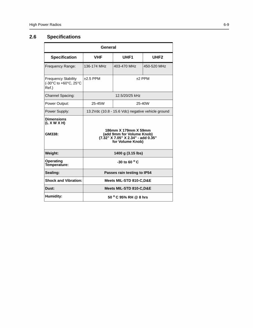
2.6 Specifications
General
Specification VHF UHF1 UHF2
Frequency Range: 136-174 MHz 403-470 MHz 450-520 MHz
Frequency Stability(-30°C to +60°C, 25°CRef.)
±2.5 PPM ±2 PPM
Channel Spacing: 12.5/20/25 kHz
Power Output: 25-45W 25-40W
Power Supply: 13.2Vdc (10.8 - 15.6 Vdc) negative vehicle ground
Dimensions(L X W X H)
GM338:186mm X 179mm X 59mm
(add 9mm for Volume Knob)(7.32” X 7.05” X 2.34” - add 0.35”
for Volume Knob)
Weight: 1400 g (3.15 lbs)
OperatingTemperature:
-30 to 60 o C
Sealing: Passes rain testing to IP54
Shock and Vibration: Meets MIL-STD 810-C,D&E
Dust: Meets MIL-STD 810-C,D&E
Humidity: 50 o C 95% RH @ 8 hrs
6-10 High Power Radios
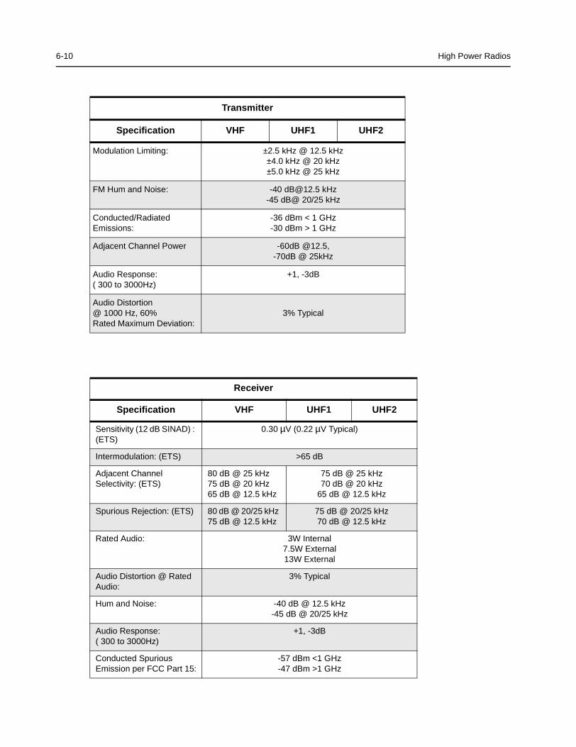
Transmitter
Specification VHF UHF1 UHF2
Modulation Limiting: ±2.5 kHz @ 12.5 kHz±4.0 kHz @ 20 kHz±5.0 kHz @ 25 kHz
FM Hum and Noise: -40 [email protected] kHz-45 dB@ 20/25 kHz
Conducted/RadiatedEmissions:
-36 dBm < 1 GHz-30 dBm > 1 GHz
Adjacent Channel Power -60dB @12.5,-70dB @ 25kHz
Audio Response:( 300 to 3000Hz)
+1, -3dB
Audio Distortion@ 1000 Hz, 60%Rated Maximum Deviation:
3% Typical
Receiver
Specification VHF UHF1 UHF2
Sensitivity (12 dB SINAD) :(ETS)
0.30 µV (0.22 µV Typical)
Intermodulation: (ETS) >65 dB
Adjacent ChannelSelectivity: (ETS)
80 dB @ 25 kHz75 dB @ 20 kHz65 dB @ 12.5 kHz
75 dB @ 25 kHz70 dB @ 20 kHz
65 dB @ 12.5 kHz
Spurious Rejection: (ETS) 80 dB @ 20/25 kHz75 dB @ 12.5 kHz
75 dB @ 20/25 kHz70 dB @ 12.5 kHz
Rated Audio: 3W Internal7.5W External13W External
Audio Distortion @ RatedAudio:
3% Typical
Hum and Noise: -40 dB @ 12.5 kHz-45 dB @ 20/25 kHz
Audio Response:( 300 to 3000Hz)
+1, -3dB
Conducted SpuriousEmission per FCC Part 15:
-57 dBm <1 GHz-47 dBm >1 GHz
G-1
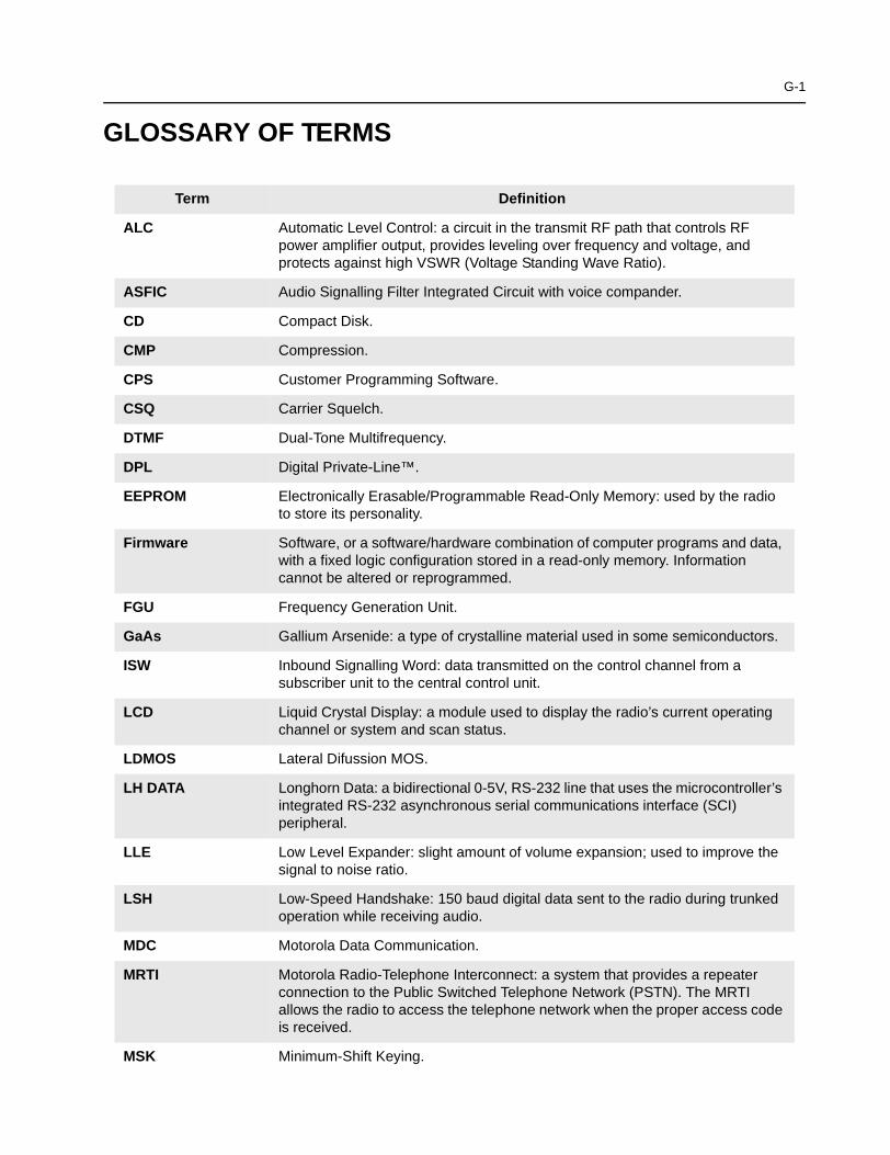
GLOSSARY OF TERMS
Term Definition
ALC Automatic Level Control: a circuit in the transmit RF path that controls RFpower amplifier output, provides leveling over frequency and voltage, andprotects against high VSWR (Voltage Standing Wave Ratio).
ASFIC Audio Signalling Filter Integrated Circuit with voice compander.
CD Compact Disk.
CMP Compression.
CPS Customer Programming Software.
CSQ Carrier Squelch.
DTMF Dual-Tone Multifrequency.
DPL Digital Private-Line™.
EEPROM Electronically Erasable/Programmable Read-Only Memory: used by the radioto store its personality.
Firmware Software, or a software/hardware combination of computer programs and data,with a fixed logic configuration stored in a read-only memory. Informationcannot be altered or reprogrammed.
FGU Frequency Generation Unit.
GaAs Gallium Arsenide: a type of crystalline material used in some semiconductors.
ISW Inbound Signalling Word: data transmitted on the control channel from asubscriber unit to the central control unit.
LCD Liquid Crystal Display: a module used to display the radio’s current operatingchannel or system and scan status.
LDMOS Lateral Difussion MOS.
LH DATA Longhorn Data: a bidirectional 0-5V, RS-232 line that uses the microcontroller’sintegrated RS-232 asynchronous serial communications interface (SCI)peripheral.
LLE Low Level Expander: slight amount of volume expansion; used to improve thesignal to noise ratio.
LSH Low-Speed Handshake: 150 baud digital data sent to the radio during trunkedoperation while receiving audio.
MDC Motorola Data Communication.
MRTI Motorola Radio-Telephone Interconnect: a system that provides a repeaterconnection to the Public Switched Telephone Network (PSTN). The MRTIallows the radio to access the telephone network when the proper access codeis received.
MSK Minimum-Shift Keying.
G-2 Glossary
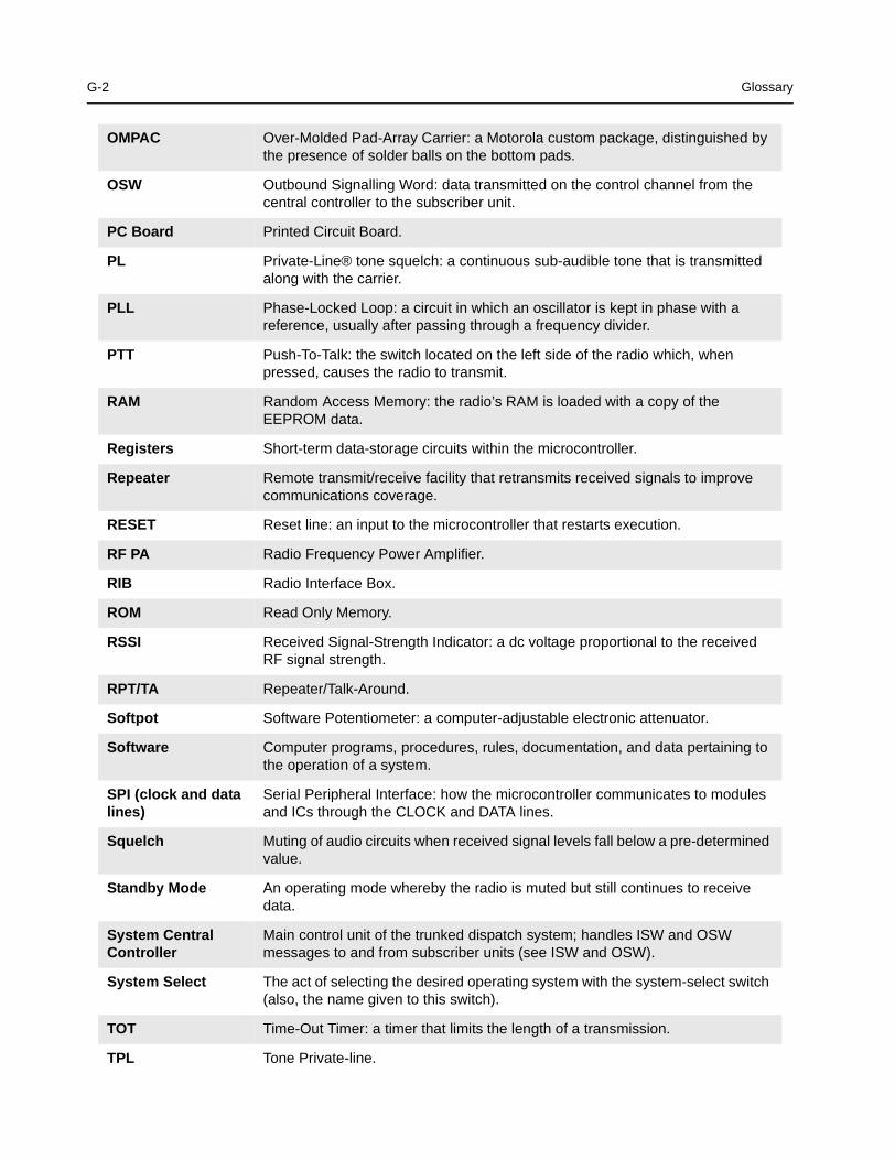
OMPAC Over-Molded Pad-Array Carrier: a Motorola custom package, distinguished bythe presence of solder balls on the bottom pads.
OSW Outbound Signalling Word: data transmitted on the control channel from thecentral controller to the subscriber unit.
PC Board Printed Circuit Board.
PL Private-Line® tone squelch: a continuous sub-audible tone that is transmittedalong with the carrier.
PLL Phase-Locked Loop: a circuit in which an oscillator is kept in phase with areference, usually after passing through a frequency divider.
PTT Push-To-Talk: the switch located on the left side of the radio which, whenpressed, causes the radio to transmit.
RAM Random Access Memory: the radio’s RAM is loaded with a copy of theEEPROM data.
Registers Short-term data-storage circuits within the microcontroller.
Repeater Remote transmit/receive facility that retransmits received signals to improvecommunications coverage.
RESET Reset line: an input to the microcontroller that restarts execution.
RF PA Radio Frequency Power Amplifier.
RIB Radio Interface Box.
ROM Read Only Memory.
RSSI Received Signal-Strength Indicator: a dc voltage proportional to the receivedRF signal strength.
RPT/TA Repeater/Talk-Around.
Softpot Software Potentiometer: a computer-adjustable electronic attenuator.
Software Computer programs, procedures, rules, documentation, and data pertaining tothe operation of a system.
SPI (clock and datalines)
Serial Peripheral Interface: how the microcontroller communicates to modulesand ICs through the CLOCK and DATA lines.
Squelch Muting of audio circuits when received signal levels fall below a pre-determinedvalue.
Standby Mode An operating mode whereby the radio is muted but still continues to receivedata.
System CentralController
Main control unit of the trunked dispatch system; handles ISW and OSWmessages to and from subscriber units (see ISW and OSW).
System Select The act of selecting the desired operating system with the system-select switch(also, the name given to this switch).
TOT Time-Out Timer: a timer that limits the length of a transmission.
TPL Tone Private-line.
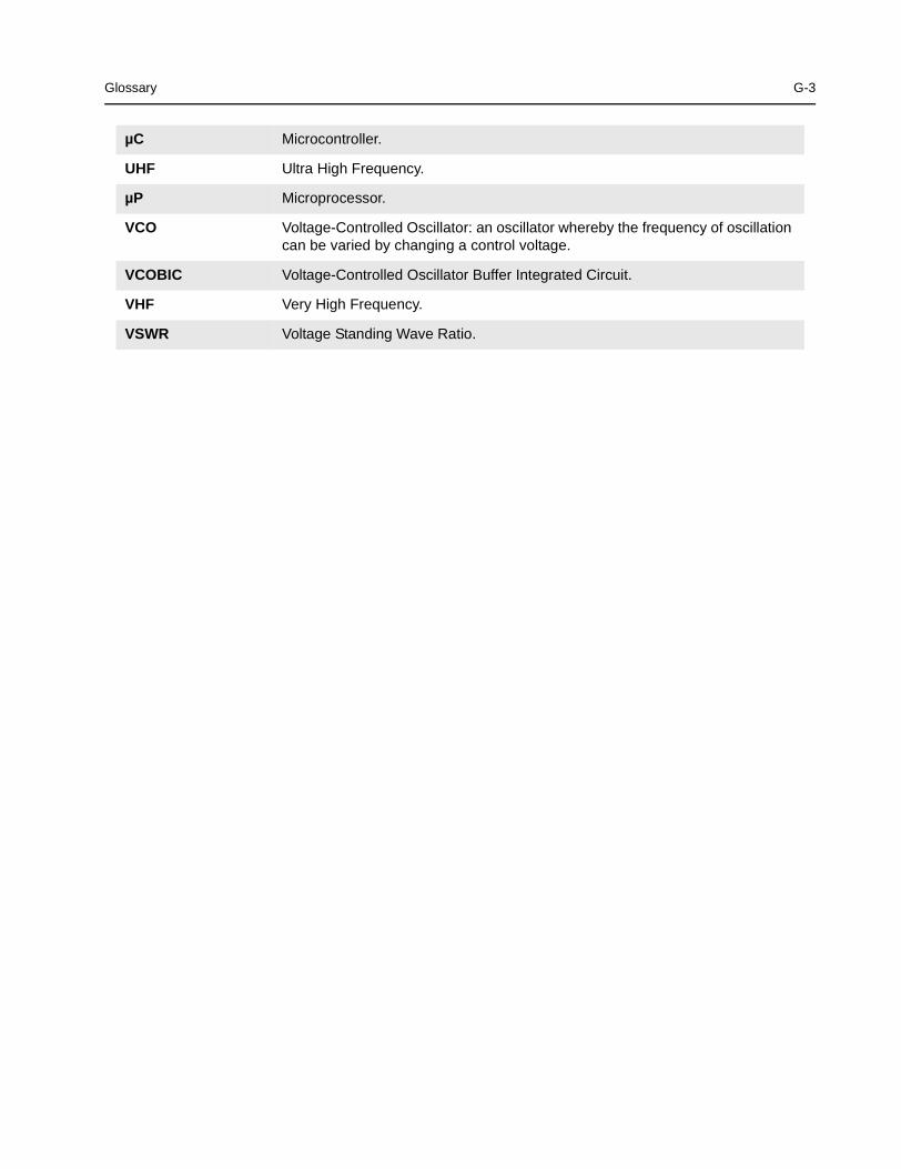
Glossary G-3
µC Microcontroller.
UHF Ultra High Frequency.
µP Microprocessor.
VCO Voltage-Controlled Oscillator: an oscillator whereby the frequency of oscillationcan be varied by changing a control voltage.
VCOBIC Voltage-Controlled Oscillator Buffer Integrated Circuit.
VHF Very High Frequency.
VSWR Voltage Standing Wave Ratio.
G-4 Glossary
Notes
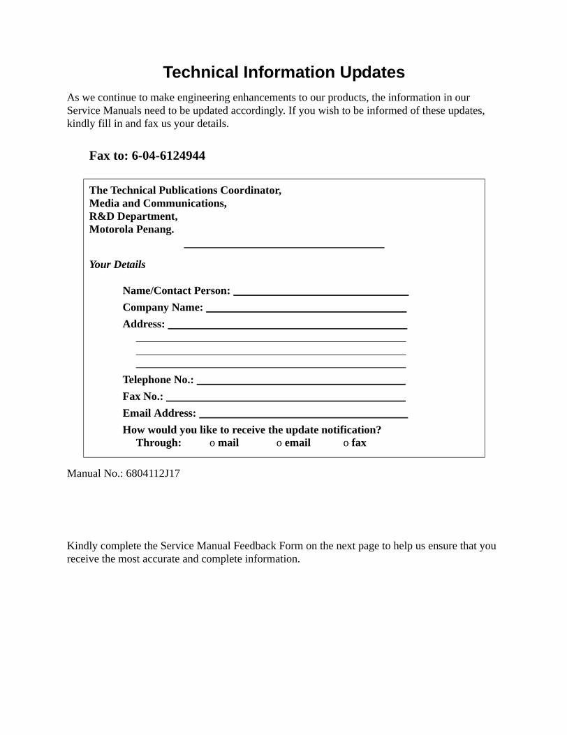
Technical Information UpdatesAs we continue to make engineering enhancements to our products, the information in ourService Manuals need to be updated accordingly. If you wish to be informed of these updates,kindly fill in and fax us your details.
Manual No.: 6804112J17
Kindly complete the Service Manual Feedback Form on the next page to help us ensure that youreceive the most accurate and complete information.
Fax to: 6-04-6124944
The Technical Publications Coordinator,Media and Communications,R&D Department,Motorola Penang.
Your Details
Name/Contact Person:
Company Name:
Address:
Telephone No.:
Fax No.:
Email Address:
How would you like to receive the update notification?Through: o mail o email o fax
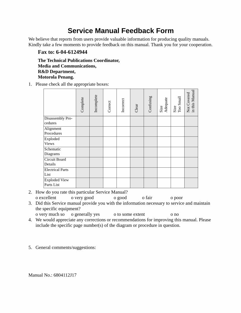
Service Manual Feedback FormWe believe that reports from users provide valuable information for producing quality manuals.Kindly take a few moments to provide feedback on this manual. Thank you for your cooperation.
1. Please check all the appropriate boxes:
2. How do you rate this particular Service Manual?o excellent o very good o good o fair o poor
3. Did this Service manual provide you with the information necessary to service and maintainthe specific equipment?o very much so o generally yes o to some extent o no
4. We would appreciate any corrections or recommendations for improving this manual. Pleaseinclude the specific page number(s) of the diagram or procedure in question.
5. General comments/suggestions:
Manual No.: 6804112J17
Fax to: 6-04-6124944
The Technical Publications Coordinator,Media and Communications,R&D Department,Motorola Penang.
Co
mpl
ete
Inco
mpl
ete
Co
rre
ct
Inco
rre
ct
Cle
ar
Co
nfu
sin
g
Siz
eA
deq
ua
te
Siz
eTo
oS
ma
ll
Not
Co
vere
din
this
Man
ual
Disassembly Pro-cedures
AlignmentProcedures
ExplodedViews
SchematicDiagrams
Circuit BoardDetails
Electrical PartsList
Exploded ViewParts List


![[XLS]diagramasde.comdiagramasde.com/diagramas/otros2/ListadePrecios.xls · Web viewMINI ECO MIXER CON AMPLIFICADOR PET PROLONGACION EJE TANDEM PF3MM PROTECTOR DE FOQUITOS 3MM PF5MM](https://img.pdfslide.us/doc/110x75/5aa360ad7f8b9a84398e4a79/xls-viewmini-eco-mixer-con-amplificador-pet-prolongacion-eje-tandem-pf3mm-protector.jpg)