Embed Size (px)
Citation preview
SERVICEMANUAL
Published in Oct. ’03
FS-1020D

Safety precautions
This booklet provides safety warnings and precautions for our service personnel to ensure the safety oftheir customers, their machines as well as themselves during maintenance activities. Service personnelare advised to read this booklet carefully to familiarize themselves with the warnings and precautionsdescribed here before engaging in maintenance activities.

indicates that action is required. The specific action required is shown inside the symbol.
General action required.
Remove the power plug from the wall outlet.
Always ground the copier.
Safety warnings and precautions
Various symbols are used to protect our service personnel and customers from physical danger andto prevent damage to their property. These symbols are described below:
DANGER: High risk of serious bodily injury or death may result from insufficient attention to or incorrect
compliance with warning messages using this symbol.
WARNING:Serious bodily injury or death may result from insufficient attention to or incorrect compliancewith warning messages using this symbol.
CAUTION:Bodily injury or damage to property may result from insufficient attention to or incorrectcompliance with warning messages using this symbol.
Symbols
The triangle ( ) symbol indicates a warning including danger and caution. The specific pointof attention is shown inside the symbol.
General warning.
Warning of risk of electric shock.
Warning of high temperature.
indicates a prohibited action. The specific prohibition is shown inside the symbol.
General prohibited action.
Disassembly prohibited.

1. Installation Precautions
WARNING
• Do not use a power supply with a voltage other than that specified. Avoid multiple connections toone outlet: they may cause fire or electric shock. When using an extension cable, always checkthat it is adequate for the rated current. ............................................................................................
• Connect the ground wire to a suitable grounding point. Not grounding the copier may cause fire orelectric shock. Connecting the earth wire to an object not approved for the purpose may causeexplosion or electric shock. Never connect the ground cable to any of the following: gas pipes,lightning rods, ground cables for telephone lines and water pipes or faucets not approved by theproper authorities. .............................................................................................................................
CAUTION:
• Do not place the copier on an infirm or angled surface: the copier may tip over, causing injury. .....
• Do not install the copier in a humid or dusty place. This may cause fire or electric shock. ..............
• Do not install the copier near a radiator, heater, other heat source or near flammable material.This may cause fire. ..........................................................................................................................
• Allow sufficient space around the copier to allow the ventilation grills to keep the machine as coolas possible. Insufficient ventilation may cause heat buildup and poor copying performance. ..........
• Always handle the machine by the correct locations when moving it. ..............................................
• Always use anti-toppling and locking devices on copiers so equipped. Failure to do this maycause the copier to move unexpectedly or topple, leading to injury. .................................................
• Avoid inhaling toner or developer excessively. Protect the eyes. If toner or developer isaccidentally ingested, drink a lot of water to dilute it in the stomach and obtain medical attentionimmediately. If it gets into the eyes, rinse immediately with copious amounts of water and obtainmedical attention. ..............................................................................................................................
• Advice customers that they must always follow the safety warnings and precautions in the copier’sinstruction handbook. ........................................................................................................................

• Check that the power cable covering is free of damage. Check that the power plug is dust-free. Ifit is dirty, clean it to remove the risk of fire or electric shock. ............................................................
• Never attempt to disassemble the optical unit in machines using lasers. Leaking laser light maydamage eyesight. ..............................................................................................................................
• Handle the charger sections with care. They are charged to high potentials and may causeelectric shock if handled improperly. .................................................................................................
CAUTION
• Wear safe clothing. If wearing loose clothing or accessories such as ties, make sure they aresafely secured so they will not be caught in rotating sections. ..........................................................
• Use utmost caution when working on a powered machine. Keep away from chains and belts. .......
• Handle the fixing section with care to avoid burns as it can be extremely hot. .................................
• Check that the fixing unit thermistor, heat and press rollers are clean. Dirt on them can causeabnormally high temperatures. ..........................................................................................................
• Do not remove the ozone filter, if any, from the copier except for routine replacement. ...................
2. Precautions for Maintenance
WARNING
• Always remove the power plug from the wall outlet before starting machine disassembly. ..............
• Always follow the procedures for maintenance described in the service manual and other relatedbrochures. .........................................................................................................................................
• Under no circumstances attempt to bypass or disable safety features including safetymechanisms and protective circuits. .................................................................................................
• Always use parts having the correct specifications. ..........................................................................
• Always use the thermostat or thermal fuse specified in the service manual or other relatedbrochure when replacing them. Using a piece of wire, for example, could lead to fire or otherserious accident. ...............................................................................................................................
• When the service manual or other serious brochure specifies a distance or gap for installation of apart, always use the correct scale and measure carefully. ...............................................................
• Always check that the copier is correctly connected to an outlet with a ground connection. ............

• Do not pull on the AC power cord or connector wires on high-voltage components when removingthem; always hold the plug itself. ......................................................................................................
• Do not route the power cable where it may be stood on or trapped. If necessary, protect it with acable cover or other appropriate item. ..............................................................................................
• Treat the ends of the wire carefully when installing a new charger wire to avoid electric leaks. .......
• Remove toner completely from electronic components. ...................................................................
• Run wire harnesses carefully so that wires will not be trapped or damaged. ...................................
• After maintenance, always check that all the parts, screws, connectors and wires that wereremoved, have been refitted correctly. Special attention should be paid to any forgottenconnector, trapped wire and missing screws. ..................................................................................
• Check that all the caution labels that should be present on the machine according to theinstruction handbook are clean and not peeling. Replace with new ones if necessary. ...................
• Handle greases and solvents with care by following the instructions below: ....................................· Use only a small amount of solvent at a time, being careful not to spill. Wipe spills off completely.· Ventilate the room well while using grease or solvents.· Allow applied solvents to evaporate completely before refitting the covers or turning the mainswitch on.
· Always wash hands afterwards.
• Never dispose of toner or toner bottles in fire. Toner may cause sparks when exposed directly tofire in a furnace, etc. ..........................................................................................................................
• Should smoke be seen coming from the copier, remove the power plug from the wall outletimmediately. ......................................................................................................................................
3. Miscellaneous
WARNING
• Never attempt to heat the drum or expose it to any organic solvents such as alcohol, other thanthe specified refiner; it may generate toxic gas. ................................................................................

2FM
1-1-1
1-1-1 Specifications
Type ............................................... DesktopPrinting system............................... Indirect electrostatic systemPaper type ...................................... Cassette: Plain paper (60 - 90 g/m2 [thick paper mode: 90 - 105 g/m2])
MP tray: Plain paper (60 - 90 g/m2 [thick paper mode: 90 - 163 g/m2])Special paper: Transparencies, letterhead, colored paper, recycled paperNote: Use the MP tray for special paper
Paper size ...................................... A4 (210 - 297 mm)B5 (182 - 257 mm)A5 (148 - 210 mm)Letter (81/2" - 11")Legal (81/2" - 14")Folio (210 - 330 mm)Oficio II (216 - 330 mm)Non-standard size (148 to 210 mm × 210 to 297 mm: cassette), (70 to 216 mm × 148 to 297 mm: MP tray)
Printing speed ................................ Simplex printing: 20 pages//min. (A4, plain), 21 pages//min. (Letter, plain)Duplex printing: 10 pages//min. (A4/Letter, plain)Note: When printing multiple copies of the same page
First print ........................................ Within 10 s (A4/Letter), depends on input dataWarm-up time ................................. Within 15 s (room temperature 23°C/73.4°F, humidity 50% RH)Paper feed system ......................... One universal cassette and one MP trayPaper loading capacity ................... Cassette: 250 sheets (80 g/m2, 0.11 µm)
MP tray: 50 sheets (80 g/m2, 0.11 µm)Paper eject system .........................Face down: 250 sheets (80 g/m2, 0.11 µm)Standard memory .......................... 16 MB, expandable up to 272 MBAdditional memory ......................... 1 slot (16/32/64/128 MB DIMM)Resolution ...................................... Fast 1200 mode
600 × 600 dpi, with KIR (Kyocera Image Refinement)300 × 300 dpi, with KIR (Kyocera Image Refinement)
Photoconductor .............................. OPC (drum diameter 30 mm)Charging system ............................ Single positive corona chargingDeveloping system ......................... Single element reversing processTransfer system ............................. Transfer rollerFixing system ................................. Heat roller
Heat source: halogen heaters (750 W)Control temperature: 180°C/356°F (at normal ambient temperature)Abnormally high temperature protection device: thermal cutout
Charge erasing system .................. Exposure by eraser lamp (LED array)Cleaning system ............................ Cleaning bladeController hardware ....................... CPU: Power PC405 (266 MHz)
System ROM: 4 MBFont ROM: 2 MB (16 Mbit × 1)Main RAM: 16 MB standard (on-board); expanding up to 272 MB (standard 16 MB+256 MB) at the maximum by adding optional expansion memoryOptional expansion RAM (DIMM): 1 slot

2FM
1-1-2
Controller software ......................... a) EmulationPCL6 (PCL5e+PCLXL)KPDL3 (PostScript 3 compatible)
b) Fonts:Bitmap font:1 Line Printer bitmap fontOutline fonts:35 PCL6 (PCL5e/PCL-XL) fonts45 KPDL2 fonts:
c) Graphic:(1) Raster graphic:
75, 100, 150, 200*, 300, 600* dpi(*200 dpi is supported when the resolution is 600 dpi.)
(2) Vector graphic:Line, Box, Circle, Arc, Fill pattern etc.
(3) Bar code:One-dimensional bar code: 45 typesTwo-dimensional bar code: 1 type (PDF-417)
d) ConnectivityPlug & play, Windows 95/98/Me/NT4.0/2000/XP
Interface ......................................... Parallel: High-speed (bi-directional), IEEE 1284 Nibble/ECP modeUSB: Full-Speed USB2.0Optional interface (KUIO-LV) × 1: Network interface card IB-20 (10 Base-TX/100Base-TX/10 Base-2), IB-21E (10 Base-TX/100 Base-TX), wireless LAN card IB-22must be installed.Optional serial interface: RS-232C (Max. 115.2 Kbps), Serial interface board IB-11must be installed.
Dimensions .................................... 378 (W) × 235 (D) × 375 (H) mm147/8" (W) × 91/4" (D) × 143/4" (H)
Weight ............................................ Approx. 10.5 kg/231/8 lbsFloor requirements ......................... 496 (W) × 740 (D) mm
199/16" (W) × 293/16" (D)Power source ................................. 120 V AC, 60 Hz, 7.1 A
220 - 240 V AC, 50/60 Hz, 3.8 APower consumption ....................... Max.: 819 W
During sleep mode: 4.5 W (120 V AC), 4.2 W (220 - 240 V AC)Noise .............................................. Printing: 55 dB(A)
Ready: 32 dB(A)Options ........................................... Paper feeder, Additional memory (DIMM), Memory card, Network interface card
IB20/IB21E/IB-22, Serial interface board IB-11

2FM
1-1-3
Figure 1-1-1
1-1-2 Name of parts
(1) Overall
1 Front top cover2 Front cover3 Process unit4 Toner container5 Main charger cleaner6 Cassette7 Paper stopper8 Face-down output tray9 MP tray
0 Extension tray! Power switch@ Memory cover# Rear cover$ Optional interface slot% Parallel interface connector^ USB interface connector& Operator panel* AC inlet
5
3
4
6
0
87
&
9
1
2
@$
^%
#
!
*

2FM
1-1-4
(2) Operator panel
1 Ready indicator (Green)2 Data indicator (Green)3 Attention indicator (Red)4 Toner indicator (Red)5 CANCEL key6 GO key
Figure 1-1-2
1
2
3
4
5
6

2FM
1-1-5
Cassette, MP trayOptional paper feederSwitch back and refeed (duplex printing)
Paper path
8
3
4
65
0 !7 21
9
(2) Cross section view
1 Cassette2 Paper feed unit3 MP tray4 MP tray paper feed unit5 Process unit6 Toner container
Figure 1-1-2
7 Transfer section8 Fuser unit9 Face-down output tray0 Switch back/conveying section! Refeed unit

2FM
1-2-1
1-2-1 Process unit (drum)Note the following when handling or storing the drum.• When removing the process unit, never expose the drum surface to strong direct light.• Keep the drum at an ambient temperature between 10°C/50°F and 32.5°C/90.5°F and at a relative humidity not higher
than 80% RH. Avoid abrupt changes in temperature and humidity.• Avoid exposure to any substance which is harmful to or may affect the quality of the drum.• Do not touch the drum surface with any object. Should it be touched by hands or stained with oil, clean it.
1-2-2 Installation environment
1. Temperature: 10 - 32.5°C/50 - 90.5°F 2. Humidity: 20 - 80%RH 3. Power supply: 120 V AC, 7.1 A
220 - 240 V AC, 3.8 A 4. Power source frequency: 50 Hz ±0.3%/60 Hz ±0.3% 5. Installation location
• Avoid direct sunlight or bright lighting. Ensure that the photoconductor will not be exposed to direct sunlight or otherstrong light when removing paper jams.
• Avoid extremes of temperature and humidity, abrupt ambient temperature changes, and hot or cold air directed ontothe machine.
• Avoid dust and vibration.• Choose a surface capable of supporting the weight of the machine.• Place the machine on a level surface (maximum allowance inclination: 1° ).• Avoid air-borne substances that may adversely affect the machine or degrade the photoconductor, such as
mercury, acidic of alkaline vapors, inorganic gasses, NOx, SOx gases and chlorine-based organic solvents.• Select a room with good ventilation.
6. Allow sufficient access for proper operation and maintenance of the machine.Machine front: 50 mm/1911/16" Machine rear: 40 mm/153/4"Machine right: 25 mm/97/8" Machine left: 25 mm/97/8"Machine above: 30 mm/1113/16"

1-3-1
2FM
1-3-1 Unpacking and installation
(1) Installation procedure
Unpack.
Connect the printer cable and power cord.
Load paper.
Inisializing the pirnter and make test print.
Start
Install a toner container.
Remove the tape and protective packing.
Completion of the machine installation.

1-3-2
2FM
Unpack.
1Printer2Power cord3 Installation guide4Toner container5Cleaning cloth6CD-ROMs7Extension tray [For U.S.A only]
Figure 1-3-1 Unpacking
3
7
2
1
4
1
2
45
67
3

1-3-3
2FM
1. Remove the two tape.
2. Pull the cassette out of the printer. 3. Remove the protective packing from inside the
cassette.
Remove the tape and protective packing
Figure 1-3-2
Figure 1-3-3
Tape
Protective packing
Cassette
1-3-4
2FM
Figure 1-3-4
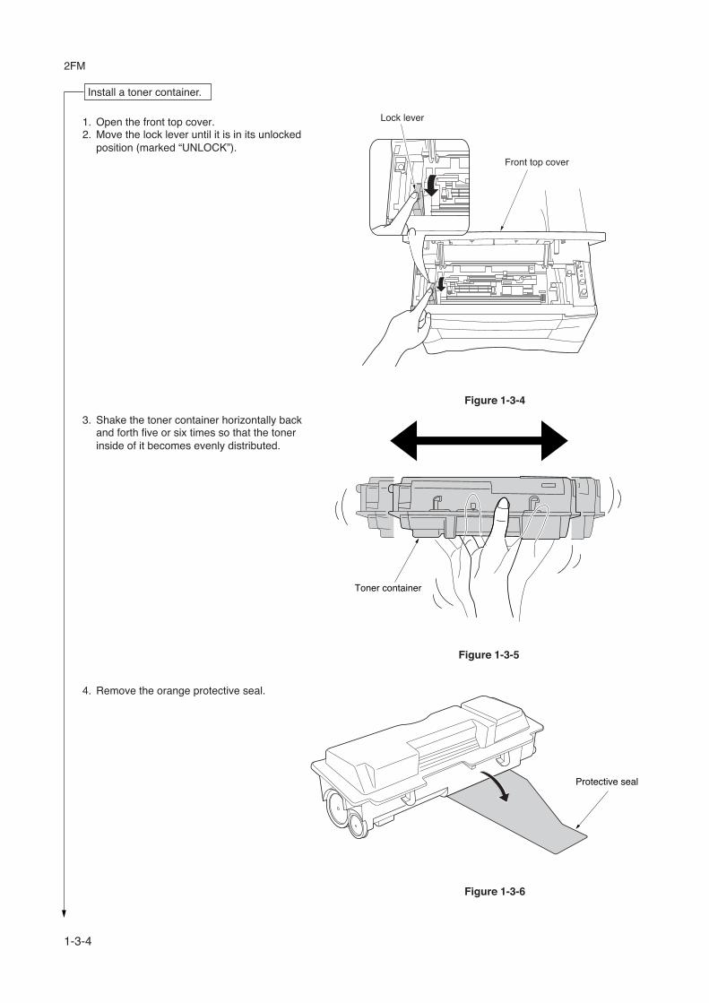
1. Open the front top cover. 2. Move the lock lever until it is in its unlocked
position (marked “UNLOCK”).
Install a toner container.
Lock lever
Front top cover
Figure 1-3-5
Figure 1-3-6
Toner container
3. Shake the toner container horizontally backand forth five or six times so that the tonerinside of it becomes evenly distributed.
Protective seal
4. Remove the orange protective seal.

1-3-5
2FM
5. Set the toner container into the process unit.
Figure 1-3-7
Figure 1-3-9
Figure 1-3-8
Toner container
Process unit
6. Push in on the areas of the toner container marked“PUSH HERE” until the container clicks into place inthe process unit.
Toner container
7. Push the lock lever back into its locked position. 8. Close the front top cover.
LO
CK
UN
LO
CK
Lock lever
Front top cover

1-3-6
2FM
1. Connect the printer cable (parallel or USB).
Figure 1-3-11
Connect the printer cable and power cord.
Parallel interface connector
Parallelprinter cable
USB interfaceconnector
USB cable
Power cord
AC inlet
2. Connect the power cord.
Figure 1-3-10

1-3-7
2FM
Figure 1-3-12
1. Pull the cassette out of the copier. 2. Set the paper in the cassette.
Figure 1-3-13
Load paper.
Cassette
Power switch
GO key
1. Turn on the printer’s power switch. Upon turningon the power, the printer’s 4 indicators flash insequence until printer initialization is complete,then the indicator ( [on line]) lights steadily.
2. The printer can print two different types of statuspage standard and service-purpose. A service-purpose status page contains more detailedinformation about printer settings than a standardstatus page.
• To print a standard status page, pressthe GO key for at least 3 seconds andthe indicators light in sequence fromtop to bottom.• To print a service-purpose statuspage, press the GO key for more than10 seconds and the indicators light insequence twice from top to bottom.
Initializing the printer and make test print.
Completion of machine installation.

1-3-8
2FM
1-3-2 Installing the expanding memory (option)
The main board of the printer is equipped with onesocket for memory expansion. Expansion memory isavailable in the form of DIMM (Dual In-line MemoryModule).
CAUTIONTake precautions that no foreign substances such asmetal chips or liquid get inside the printer during theinstallation process. Operation of the printer during thepresence of a foreign substance may lead to fire orelectric shock.
WARNINGTurn the printer’s power switch off. Unplug the printer’spower cable.
Procedure 1. Remove the one screw and then remove the
memory cover. 2. Open the clips on both ends of the DIMM socket. 3. Insert the DIMM into the DIMM socket so that the
notches on the DIMM align with the correspondingprotrusions in the slot.
4. Close the clips on the DIMM slot to secure theDIMM.
Figure 1-3-14 Inserting the DIMM
Memory cover
Screw
Memory socket
DIMM Clip
Clip

1-3-9
2FM
1-3-3 Installing the memory card (option)
The main board of the printer is equipped with oneslot for memory card.
CAUTIONTake precautions that no foreign substances such asmetal chips or liquid get inside the printer during theinstallation process. Operation of the printer during thepresence of a foreign substance may lead to fire orelectric shock.
WARNINGTurn the printer’s power switch off. Unplug theprinter’s power cable and disconnect the printer fromthe computer or the network. Never insert or remove amemory card while the printer power is ON.
Failure to turn the power switch OFF will immediatelyhalt the printer with a [Memory card err20]message (this message may not always appear). Italso could result in any damage to the printer’selectronic parts or the memory card. Turn the powerswitch ON again to restart the printer.
Procedure 1. Remove the two screws and then remove the
option interface slot cover (or network interfacecard/serial interface board).
2. Insert the memory card in the slot. Push it in allthe way.
3. Secure the option interface slot cover (or networkinterface card/serial interface board) by using twoscrews.
Figure 1-3-15 Inserting the memory card
Screws
Memory card
Option interface slot cover

1-3-10
2FM
1-3-4 Installing the network interface card (option)
If the serial interface board kit is installed, remove it to use the network interface card.
Figure 1-3-16 Inserting the network interface card
Screws
Network interface card
Screws
Option interface slot cover
CAUTIONTake precautions that no foreign substances such asmetal chips or liquid get inside the printer during theinstallation process. Operation of the printer during thepresence of a foreign substance may lead to fire orelectric shock.
WARNINGTurn the printer’s power switch off. Unplug the printer’spower cable.
Procedure 1. Remove the two screws and then remove the option
interface slot cover (or the serial interface board). 2. Insert the network interface card in the slot. Push it in
all the way. 3. Secure the network interface card by using two
screws.

2FM
1-4-1
1-4-1 Paper misfeed detection
(1) Paper misfeed indicationIf a paper jam occurs while printing, the printer notifies it by the following combination of the four indicators. Remove thejammed paper as described below. After removal, open and close the top cover once to initialize the jam sensing.
Figure 1-4-1 Paper misfeed indication
Fast flashing
Lit
Off
Off
(2) Paper misfeed detection
Cassette, MP trayOptional paper feederSwitch back and refeed (duplex printing)
Paper path
MP paper sensor
Registration sensor
Exit sensor
Paper sensor
Figure 1-4-2

2FM
1-4-2
(2) Self diagnostic inidication
1-4-2 Self-diagnosis
(1) Self-diagnostic functionService errors are represented by the alternating flashing of the indicators (LEDs). Each error is represented by the notationof four digits code and can be monitored on the Remote Operation Panel utility. e.g. Call service 2000 is for the main motorerror.
(Off)
(Off)
(Off)
(Off)
Green
Red
(Lit)
(Lit)
(Lit)
(Lit)
Call service 2000
Figure 1-4-1 Self diagnostic inidication

2FM
1-4-3
Code Error indications Contents
Check procedures/corrective measures
Connect circuit tester to pin 8 (MOTORN) of YC04 on engine board (KP-1046) and ground.
Turn printer power off, then on.
Print status page.
Print status page.
Turn power switch off, then on.
Connect oscilloscope to pin 8 (MOTORN) and pin 7 (MRDYN) of CN1 on main motor.
Does pin 8 (MOTORN)
of YC04 on engine board (KP-1046) goes high,
then low?
+24 V DC at pin 9 of CN1 on
main motor?
Yes
Yes
No No
Replace engine board (KP-1046). See page 1-5-9.
Does pin 7 (MRDYN)
of CN1 on main motor goes high, then low, within 3 seconds
from pin 8 (MOTORN) goes low?
Replace main motor. See page 1-5-15. If not solved, check or replace drive unit. See page 1-5-15.
Remove and check harness (2DC2711) between engine board (KP-1046) and main motor at pins 6 to 9 onboth ends.
Yes
Yes
No
No
Replace harness (2DC2711) between engine board (KP-1046) and main motor.
OK?
START
2000 Main motor error

2FM
1-4-4
Code Error indications Contents
Check procedures/corrective measures
Yes
Yes
Yes
No
No
No
NoNo
No
Connect oscilloscope to pin 1 (PLGCLK) and pin 3 (PLGDRN) of YC06 on engine board (KP-1046).
Turn power switch off, then on.
Turn power switch off, then on.
Turn power switch on.
+24 V DC at pin 5 of YC06 on engine board
(KP-1046) ?
Doespin 3 (PLGDRN) of
YC06 on engine board (KP-1046) goes high,
then low?
Doespin 1 (PLGCLK) of
YC06 on engine board (KP-1046) output
square-wave* signal?
Does pin 2 (PLGRDYN) of YC6 on
engine board (KP-1046) goes high, then low, within 8 seconds
after pin 3 (PLGDRN) goes high, then
low?
Replace engine board (KP-1046). See page 1-5-9.
Replace harness (2DC2714) between engine bard and laser scanner unit.
Replace harness (2DC2714) between engine board and laser scanner unit.
Yes
Replace engine board (KP-1046). See page 5-11.
Replace engine board (KP-1046). See page 1-5-9.
Replace laser scanner unit. See page 1-5-28.
Connect oscilloscope to pin 2 (PLGRDYN) and pin 3 (PLGDRN) of YC06 on engine board (KP-1046).
*: 1417 Hz (705 µs)
OK?
OK?
Yes
Yes
Yes
Turn power switch on.
Replace laser scanner unit. See page 5-29.
Turn power switch on.
OK?
End.
End.
End.
AContinuedto next page.
No
START
4000 Laser scanner unit [Polygon motor] error

2FM
1-4-5
Check procedures/corrective measures
No
No
Turn power switch on.
Replace harness (2FM2602) between engine board and main board.
Replace engine board (KP-1046). See page 1-5-9.
OK?
Yes
Yes
Turn power switch on.
OK?
End.
End.
A
Continuedfrom previous page.
Replace main board (KP-1050). See page 1-5-10.

2FM
1-4-6
Code Error indications Contents
Check procedures/corrective measures
Yes
Yes
No
No
No
No
No
Connect oscilloscope to pin 4 (OUTPEN) of YC07 on main board (KP-1050).
Turn power switch off, then on.
Turn power switch off, then on.
Turn power switch on.
+5 V DC at pin 6 of YC07 on main board
(KP-1050) ?
Doespin 4 (OUTPEN) of
YC06 on main board (KP-1050) goes high, then low
before "4200" error?
Does pin 8 (PDN) of YC06 on
main board (KP-1050) output pulse signal*, within 0.1 second
after pin 4 (OUTPEN) goes high, then
low?
Replace harness (2FM2602) between main board and engine board.
YesReplace main board(KP-1050). See page 1-5-10.
Replace main board (KP-1050). See page 1-5-10.
Connect oscilloscope to pin 4 (OUTPEN) and pin 8 (PDN) of YC07 on main board (KP-1050).
OK?
Yes
Yes
Turn power switch on.
OK?
End.
End.
Replace engine board (KP-1051). See page 1-5-9.
B CContinued
to next page.Continued
to next page.
*: Pin photo diode detect horizontal synchronization signal(Frequency: 1417 Hz,Low level width: 10 µs)
START
4200 Laser scanner unit [Pin photo diode] error

2FM
1-4-7
Check procedures/corrective measures
No
No
Turn power switch on.
Turn power switch on.
Turn power switch on.
Turn power switch on.
Replace laser scanner unit. See page 1-5-28.
OK?
Yes
OK?Yes
No
OK?Yes
No
OK?Yes
End.
End.
B
Continuedfrom previous page.
Replace engine board (KP-1046). See page 1-5-9.
NoOK?
Replace engine board (KP-1046). See page 1-5-9.
Replace main board (KP-1050). See page 1-5-10.
No
Turn power switch on.
OK?
Yes
Yes
End.
End.
C
Continuedfrom previous page.
Replace main board (KP-1050). See page 1-5-10.
Replace harness (2DC2714) between engine board and laser scanner unit.
Replace harness (2FM2602) between main board and engine board.
Replace harness (2FM2602) between main board and engine board.
Replace harness (2DC2714) between main board and laser scanner unit.

2FM
1-4-8
Code Error indications Contents
Check procedures/corrective measures
Yes
Yes
Yes
No
No
Turn power switch off, and remove power cable.
Detach connector CN4 on power supply board.
Detach connector CN1 on power supply board.
Measure resistance between pins 1 and 2 of the detached connector.
Replace fuser thermistor. See page 1-5-25.
Replace thermal cutout or heater lamp. See page 1-5-26 or 1-5-22.
Replace bias board or high voltage board or power supply board. See page 1-5-13 or 1-5-12.
Open (infinite)?
No
No
Open (infinite)?
Measure resistance between pins 1 and 3 of the detached connector.
Replace harness (2FM2601) between engine board (KP-1046) and bias board (KP-1051).
End.
Yes
No
Replace engine board (KP-1046). See page 1-5-9.
"6000" error shown?
"6000" error shown?
START
6000 Fuser unit error

2FM
1-4-9
Code Error indications Contents
Check procedures/corrective measures
Replace the waste toner sensor or engine board.
Yes
Yes
No
No
Shake the process unit horizontally.
Turn power switch off, then on.
Replace the process unit.
"7980" error shown?
Turn power switch off, then on.
End.
"7980" error shown?
START
7980 Waste toner full [Total page count less than 100,000 pagesof printing]

2FM
1-4-10
Code Error indications Contents
Check procedures/corrective measures
Yes
Yes
No
No
Shake the process unit horizontally.
Turn power switch off, then on.
Replace the process unit.
Turn power switch off, then on.
"7990" error shown?
End.
End.
"7990" error shown?
Replace the waste toner sensor or engine board (KP-1046). See page 1-5-9.
START
7990 Waste toner full [Total page count more than 100,000 pagesof printing]

2FM
1-4-11
Code Error indicationsCheck procedures/corrective
measuresContents
F010 Controller checksumerror
F020 Controller RAM read/write error
F030 Controller system er-ror
F040 Communicaton error
F050 Engine ROMchecksum error
Turn power switch off, then on. If notsolved, replace main board (Seepage 1-5-10).
Remove the expansion memory(DIMM). Turn power switch off, thenon. If not solved, replace main board.If solved, replace the expandingmemory (See pages 1-5-10 and 1-3-8).
Turn power switch off, then on. If notsolved, replace main board (Seepage 1-5-10).
Turn power switch off, then on. If notsolved, replace engine board (Seepage 1-5-9) or main board (See page1-5-10).
Turn power switch off, then on. If notsolved, replace engine board (Seepage 5-12).

2FM
1-4-12
1-4-3 Image formation problems
(1) No image appears(entirely white).
See page 1-4-13
(2) No image appears(entirely black).
See page 1-4-13
(3) Image is too light.
See page 1-4-13
(4) Background is visible.
See page 1-4-14
(5) A white line appearslongitudinally.
See page 1-4-14
(6) A black line appearslongitudinally.
See page 1-4-15
(7) A black line appearslaterally.
See page 1-4-15
(8) One side of the copyimage is darker thanthe other.
See page 1-4-15
(9) Black dots appear onthe image.
See page 1-4-16
(10) Image is blurred.
See page 1-4-16
(11)Paper creases.
See page 1-4-16
(12)Offset occurs.
See page 1-4-17
(14)Fixing is poor.
See page 1-4-17
(13) Image is partly missing.
See page 1-4-17
2FM
1-4-13
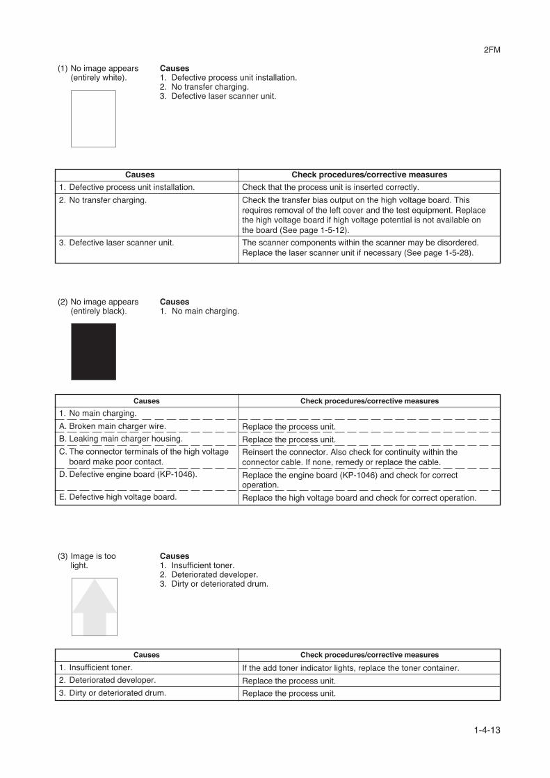
(3) Image is toolight.
Causes1. Insufficient toner.2. Deteriorated developer.3. Dirty or deteriorated drum.
Causes Check procedures/corrective measures
1. Insufficient toner.
2. Deteriorated developer.
3. Dirty or deteriorated drum.
If the add toner indicator lights, replace the toner container.
Replace the process unit.
Replace the process unit.
(1) No image appears(entirely white).
Causes1. Defective process unit installation.2. No transfer charging.3. Defective laser scanner unit.
Causes Check procedures/corrective measures
1. Defective process unit installation.
2. No transfer charging.
3. Defective laser scanner unit.
Check that the process unit is inserted correctly.
Check the transfer bias output on the high voltage board. Thisrequires removal of the left cover and the test equipment. Replacethe high voltage board if high voltage potential is not available onthe board (See page 1-5-12).
The scanner components within the scanner may be disordered.Replace the laser scanner unit if necessary (See page 1-5-28).
Causes Check procedures/corrective measures
1. No main charging.
A. Broken main charger wire.
B. Leaking main charger housing.
C. The connector terminals of the high voltageboard make poor contact.
D. Defective engine board (KP-1046).
E. Defective high voltage board.
(2) No image appears(entirely black).
Causes1. No main charging.
Replace the process unit.
Replace the process unit.
Reinsert the connector. Also check for continuity within theconnector cable. If none, remedy or replace the cable.
Replace the engine board (KP-1046) and check for correctoperation.
Replace the high voltage board and check for correct operation.

2FM
1-4-14
Causes Check procedures/corrective measures
1. Dirty or flawed main charger wire.
2. Foreign matter in the developing section.
3. Flawed drum.
(5) A white line appearslongitudinally.
Causes1. Dirty or flawed main charger wire.2. Foreign matter in the developing section.3. Flawed drum.
(4) Background is visible.
Causes Check procedures/corrective measures
1. Dicective print density setting.
2. Dicective surface potential of the drum.
3. Defective developing roller.
Replace the process unit.
Replace the process unit.
Replace the process unit.
Open the printer top cover and check that the process unit iscorrectly seated. Poor contact maincharger terminal between the process unit and the printer main unit.
The drum potential should be approximately 400 V. This may varydepending on production lots.Measurement is possible only by using the jig and tool specificallydesigned for this purpose. The drum unit will have to be replaced if itbears values far out of the allowable range.
If a process unit which is known to work normally is available forcheck, replace the current process unit in the printer with the normalone. If the symptom disappears, replace the process unit with a newone.
Causes1. Dicective print density setting.2. Dicective surface potential of the drum.3. Defective developing roller.

2FM
1-4-15
Causes Check procedures/corrective measures
1. Contaminated main charger wire.
2. Dirty or flawed drum.
3. Deformed or worn cleaning blade.
4. Deceftive magnet roller (in the process unit).
(6) A black line appearslongitudinally.
Causes1. Contaminated main charger wire.2. Dirty or flawed drum.3. Deformed or worn cleaning blade.4. Deceftive magnet roller (in the process unit).
Clean the main charger wire by pulling the green colored cleaningknob in and out several times.
Replace the process unit.
Replace the process unit.
Replace the process unit.
Causes Check procedures/corrective measures
1. Defective process unit's grouniding.
2. Flawed drum.
3. Dirty developing section.
4. Leaking main charger housing.
Causes Check procedures/corrective measures
1. Dirty main charger wire.
(7) A black line ap-pears laterally.
Causes1. Defective process unit's grouniding2. Flawed drum.3. Dirty developing section.4. Leaking main charger housing.
(8) One side of thecopy image isdarker than theother.
Causes1. Dirty main charger wire.
The drum axle in the process unit and its counter part, the groundingtab in the printer, must be in a good contact. If necessary, apply asmall amount of electro-conductive grease onto the tab.
Replace the process unit.
Replace the process unit.
Replace the process unit.
Replace the process unit.

2FM
1-4-16
(10) Image is blurred.
(9) Black dots appearon the image.
Causes1. Dirty or flawed drum.2. Dirty contact glass.3. Deformed or worn cleaning blade.
Causes Check procedures/corrective measures
1. Dirty or flawed drum.
2. Dirty contact glass.
3. Deformed or worn cleaning blade.
Causes1. Deformed press roller.2. Paper conveying section drive problem.
Causes Check procedures/corrective measures
1. Deformed press roller.
2. Paper conveying section drive problem.
Replace the press roller (see page 1-6-26).
Check the gears and belts and, if necessary, grease them.
Replace the process unit.
Clean the contact glass.
Replace the process unit.
(11)Paper creases. Causes1. Paper curled.2. Paper damp.
Causes Check procedures/corrective measures
1. Paper curled. Check the paper storage conditions.
2. Paper damp. Check the paper storage conditions.

2FM
1-4-17
(13) Image is partly miss-ing.
Causes1. Paper damp.2. Paper creased.3. Flawed drum.
Causes Check procedures/corrective measures
1. Paper damp. Check the paper storage conditions.
2. Paper creased. Replace the paper.
3. Flawed drum. Replace the process unit.
(14)Fixing is poor. Causes1. Wrong paper.2. Flawed press roller.
Causes Check procedures/corrective measures
1. Wrong paper. Check if the paper meets specifications.
2. Flawed press roller. Replace the press roller (see page 1-6-26).
(12)Offset occurs. Causes1. Defective cleaning blade.
Causes Check procedures/corrective measures
1. Defective cleaning blade. Replace the process unit.

2FM
1-4-18
1-4-4 Electrical problems
Problem Causes Check procedures/corrective measures
(1)The machine doesnot operate whenthe power switch isturned on.
(2)The main motordoes not operate.
(3)Cooling fan doesnot operate.
(4)The feed clutchdoes not operate.
(5)The MP feed clutchdoes not operate.
No electricity at the poweroutlet.
The power cord is notplugged in properly.
The front cover is notclosed completely.
Broken power cord.
Defective power switch.
Blown fuse in the powersupply board.
Defective interlock switch.
Defective power supplyboard.
Poor contact in the mainmotor connector terminals.
Broken main motor gear.
Defective main motor.
Defective engine board(KP-1046).
Broken Cooling fan coil.
Poor contact in the Cool-ing fan connector termi-nals.
Broken feed clutch coil.
Poor contact in the feedclutch connector terminals.
Defective engine board(KP-1046).
Broken MP feed clutchcoil.
Poor contact in the MPfeed clutch connector ter-minals.
Defective engine board(KP-1046).
Measure the input voltage.
Check the contact between the power plug and the outlet.
Check the front cover.
Check for continuity. If none, replace the cord.
Check for continuity across the contacts. If none, replace thepower switch.
Check for continuity. If none, remove the cause of blowing andreplace the fuse.
Check for continuity across the contacts of switch. If none, re-place the switch.
With AC present, check for 24 V DC at CN2-12, 2-13 and 5 VDC at CN2-1, 2-2 on the power supply board. If none, replacethe power supply board.
Reinsert the connector. Also check for continuity within the con-nector cable. If none, remedy or replace the cable.
Check visually and replace the main motor if necessary.
Run maintenance item U030 and check if the main motor oper-ates and replace the main motor if necessary.
Replace the engine board (KP-1046).
Check for continuity across the coil. If none, replace Cooling fan.
Reinsert the connector. Also check for continuity within the con-nector cable. If none, remedy or replace the cable.
Check for continuity across the coil. If none, replace the feedclutch.
Reinsert the connector. Also check for continuity within the con-nector cable. If none, remedy or replace the cable.
Replace the engine board (KP-1046).
Check for continuity across the coil. If none, replace the MP feedclutch.
Reinsert the connector. Also check for continuity within the con-nector cable. If none, remedy or replace the cable.
Replace the engine board (KP-1046).

2FM
1-4-19
Problem Causes Check procedures/corrective measures
(6)The registrationclutch does not op-erate.
(7)The eraser lampdoes not turn on.
(8)The heater lampdoes not turn on.
(9)The heater lampdoes not turn off.
(10)Main charging is notperformed.
(11)Transfer charging isnot performed.
(12)A paper jam in thepaper feed or exitsection is indicatedwhen the powerswitch is turned on.
Broken registration clutchcoil.
Poor contact in the regis-tration clutch connectorterminals.
Defective engine board(KP-1046).
Poor contact in the eraserlamp connector terminals.
Defective eraser lamp.
Defective engine board(KP-1046).
Broken wire in heaterlamp.
Thermal cutout triggered.
Broken heater lamp wire.
Dirty sensor part of thethermistor.
Broken main charger wire.
Leaking main chargerhousing.
Poor contact in the highvoltage board connectorterminals.
Defective engine board(KP-1046).
Defective high voltageboard.
Poor contact in the highvoltage board connectorterminals.
Defective engine board(KP-1046).
Defective high voltageboard.
A piece of paper torn fromcopy paper is caughtaround registration sensoror exit sensor.
Defective registration sen-sor.
Defective exit sensor.
Check for continuity across the coil. If none, replace the registra-tion clutch.
Reinsert the connector. Also check for continuity within the con-nector cable. If none, remedy or replace the cable.
Replace the engine board (KP-1046).
Reinsert the connector. Also check for continuity within the con-nector cable. If none, remedy or replace the cable.
Check for continuity. If none, replace the eraser lamp.
If the eraser lamp turns on when YC14-2 on the engine board(KP-1046) is held low, replace the engine board (KP-1046).
Check for continuity across heater lamp. If none, replace theheater lamp.
Check for continuity across thermal cutout. If none, remove thecause and replace the thermal cutout.
Measure the resistance. If it is ∞Ω, replace the thermistor.
Check visually and clean the thermistor sensor parts.
See page 1-4-14.
See page 1-4-14.
Check and remove if any.
Replace registration sensor if indication of the correspondingsensor is not light.
Replace exit sensor if indication of the corresponding sensor isnot light.

2FM
1-4-20
Problem Causes Check procedures/corrective measures
(13)The LED indicatorrequesting cover tobe closed is dis-played when thefront cover isclosed.
(14)Others.
Poor contact in the con-nector terminals of inter-lock switch.
Defective interlock switch.
Wiring is broken, shortedor makes poor contact.
Noise.
Reinsert the connector. Also check for continuity within the con-nector cable. If none, remedy or replace the cable.
Check for continuity across switch. If there is no continuity whenthe switch is on, replace it.
Check for continuity. If none, repair.
Locate the source of noise and remove.

2FM
1-4-21
Clean with isopropyl alcohol.
Check visually and replace any deformedrollers (see page 1-5-5, 1-5-6).
See pages 1-4-18.
Clean with isopropyl alcohol.
See page 1-4-19.
Repair or replace if necessary .
Check the drawer claw visually and corrector replace if necessary.
Change the paper.
Check visually and replace any deformedguides.
Check visually and remedy if necessary.
Clean or replace the press roller.
Repair if any springs are off the separationclaws.
Grease the bearings and gears.
Correct.
(1)No primary paper feed.
(2)No secondary paperfeed.
(3)Skewed paper feed.
(4)Multiple sheets of paperare fed at one time.
(5)Paper jams.
(6)Abnormal noise isheard.
Check if the surfaces of the feed roller andMP feed roller are dirty with paper powder.
Check if the feed roller and MP feed rollerare deformed.
Electrical problem with the feed clutch andMP feed clutch.
Check if the surfaces of the upper and lowerregistration rollers are dirty with paper pow-der.
Electrical problem with the registrationclutch.
Deformed feed roller or MP feed roller.
Defective feed roller, MP feed roller or fric-tion plate.
Check if the paper is curled.
Deformed guides along the paper conveyingpath.
Check if the contact between the upper andlower registration rollers is correct.
Check if the press roller is extremely dirty ordeformed.
Check if the contact between the heat rollerand its separation claws is correct.
Check if the rollers and gears operatesmoothly.
Check if the following electromagneticclutches are installed correctly: feed clutch,MP feed clutch and registration clutch.
Problem Causes/check procedures Corrective measures
1-4-5 Mechanical problems

2FM
1-5-1
1-5-1 Precautions for assembly and disassembly
(1) Precautions• Be sure to turn the power switch off and disconnect the power plug before starting disassembly.• When handling PWBs (printed wiring boards), do not touch parts with bare hands. The PWBs are susceptible to static
charge.• Do not touch any PWB containing ICs with bare hands or any object prone to static charge.• Use only the specified parts to replace the fixing unit thermal cutout. Never substitute electric wires, as the printer may
be seriously damaged.• Use the following circuit testers when measuring voltages:
Hioki 3200Sanwa MD-180CSanwa YX-360TRBeckman TECH300Beckman DM45Beckman 330*Beckman 3030*Beckman DM850*Fluke 8060A*Arlec DMM1050Arlec YF1030C* Capable of measuring RMS values.

2FM
1-5-2
1-5-2 Removing the process unit
1. Open the front top cover.2. Open the front cover.3. Lift the process unit together with the toner container out of the printer.
Figure 1-5-1 Removing the process unit
CAUTIONS• After removing the process unit, seal it in the protective bag and place it on flat surface. Do not place the process unit in
a dusty area.• Do not give impact to the process unit.• Do not place floppy disks near the process unit.
Front top cover
Front cover
Process unit

2FM
1-5-3
1-5-3 Removing the principal outer covers
(1) Removing the front top cover/face-down output tray 1. Open the front top cover. 2. Remove two screws. 3. Remove the top cover/face-down output tray.
Figure 1-5-2 Removing the top cover/face-down output tray
Screws
Top cover
Top cover/face-down output tray

2FM
1-5-4
(2) Removing the right cover 1. Remove one screw. 2. Remove the side cover. 3. Unlatch the six snaps and one hook hole on
the chassis, remove the right cover.
Figure 5-2-3 Removing the right cover
(3) Removing the left cover 1. Unlatch the six snaps and two hook holes on
the chassis, remove the left cover.
Figure 1-5-4 Removing the right cover
Right cover
Right cover
Screw
Side coverSnap/Hook(inside cover)
Left cover
Left cover
Snap/Hook(inside cover)

2FM
1-5-5
1-5-4 Removing the feed roller
CAUTIONWhen refit the feed roller, fit the D-cut shaft into the D-shape hole of the feed roller.
1. Remove the paper cassette and the processunit. (See page 1-5-2)
2. Stand the machine the front side up. 3. Move the feed roller in the direction A and
remove the feed roller.
Figure 1-5-5 Removing the feed roller
A
Feed roller

2FM
1-5-6
1-5-5 Removing the MP feed roller
1. Remove the engine board (See page 1-5-9).2. Remove one screw.3. Remove the grounding plate.4. Remove one stop ring.5. Remove the MP feed clutch.
Figure 1-5-6 Removing the MP feed clutch
MP feed clutch
Grounding plate
Screw
Stop ring

2FM
1-5-7
6. Remove one screw.7. Remove the toner sensor and spring.8. While pressing the latch by using the driver and then remove the paper guide.9. Remove two screws and then remove the MP feed unit.
Figure 1-5-7 Removing the MP feed unit
10. Remove one stop ring and then remove the MP feed roller.
Figure 1-5-8 Removing the MP feed roller
Screw
Screw
Screw
Toner sensor
SpringPaper guide
Paper guide
Latch
MP feed unit
MP feed roller
Stop ring
MP feed unit

2FM
1-5-8
1-5-6 Removing the transfer roller
CAUTIONDo not touch the transfer roller (sponge) surface. Oil and dust (particles of paper, etc.) on the transfer roller cansignificantly deteriorate the print quality (white spots, etc.).
When refitting the bushes and springs, make sure to refit the black colored bush and spring on the left side. Also,observe the correct direction to which the bush is fit in reference to the paper passing direction.
1. Remove the process unit (See page 1-5-2).2. Remove the transfer roller from the both bushes.
Figure 1-5-9 Removing the transfer roller
Long Short
Paper passing direction
Transfer roller
Bush
Bush (Black colored)
Spring(Black colored)
Bush
Gear
Spring
Transfer roller
Transfer roller
2FM
1-5-9
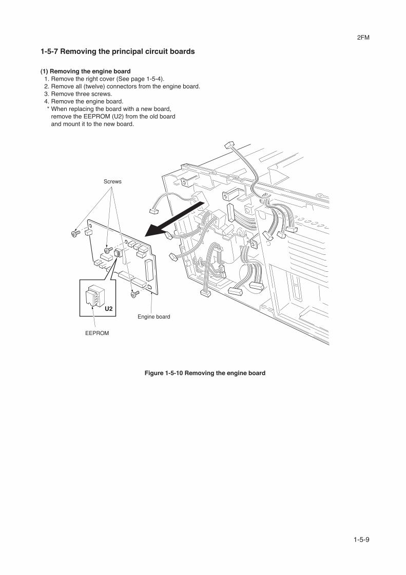
1-5-7 Removing the principal circuit boards
(1) Removing the engine board1. Remove the right cover (See page 1-5-4).2. Remove all (twelve) connectors from the engine board.3. Remove three screws.4. Remove the engine board.* When replacing the board with a new board,
remove the EEPROM (U2) from the old boardand mount it to the new board.
Figure 1-5-10 Removing the engine board
EEPROM
Engine board
Screws
2FM
1-5-10
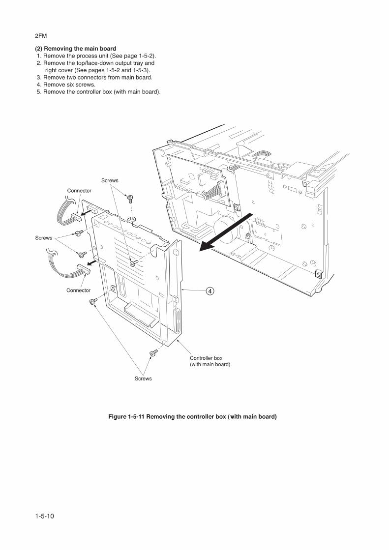
(2) Removing the main board 1. Remove the process unit (See page 1-5-2). 2. Remove the top/face-down output tray and
right cover (See pages 1-5-2 and 1-5-3). 3. Remove two connectors from main board. 4. Remove six screws. 5. Remove the controller box (with main board).
Figure 1-5-11 Removing the controller box (with main board)
4
Connector
Screws
Screws
Connector
Screws
Controller box(with main board)

2FM
1-5-11
6. Remove two screws at the back of the mainboard.
7. Remove three screws from the parallelinterface connector and USB connector.
8. Remove the main board.
Figure 1-5-12 Removing the main boar
Screws
Main board
Controller box
Screws
USB interfaceconnector
Parallel interfaceconnector

2FM
1-5-12
(3) Removing the power supply board and high voltage board1. Remove the process unit (See page 1-5-2).2. Remove the left cover (See page 1-5-4).3. Remove three connectors from the power supply board.4. Remove nine screws.5. Remove the power supply board and high voltage board. (Note: The high voltage board is directly connected to the
bias board.)6. Separate the high voltage board from the power supply board.
Figure 1-5-13 Removing the power supply board and high voltage board
Power supply board
Screws
Connectors
Screws
Screws
High voltage board
Bias board

2FM
1-5-13
(4) Removing the bias board 1. Remove the cassette and process unit (See page 1-5-2). 2. Remove the left cover (See page 1-5-4). 3. Remove the power supply board and high voltage board (See the previous page). 4. Turn the machine with the bottom side up. 5. Remove the one stop ring and then remove the roller guide. 6. Remove two axis pins and then remove the conveying guide.
Figure 1-5-14 Removing the conveying guide
Stop ring
Roller guide
Conveying guide
Axis pins

2FM
1-5-14
7. Remove five screws. 8. Remove the bottom cover. 9. Remove the three connectors from the bias board.10. Remove the bias board.
Figure 1-5-15 Removing the bias board
Connectors
Connector
Bottom cover
Bias board
ScrewsScrews

2FM
1-5-15
Main motor
Screws
Screws
Connectors
1-5-8 Removing the main motor and drive unit
1. Remove the cassette and process unit (See page 1-5-2).2. Remove the right cover (See page 1-5-4).3. Remove three connectors from the main motor.4. Remove four screws.5. Remove main motor.
Figure 1-5-16 Removing the main motor

2FM
1-5-16
6. Remove the engine board (See page 1-5-9).7. Remove wires from wire saddles on the cord cover.8. Remove one screw.9. Remove the cord cover.
Wire saddle
Wire saddlesCord cover
Screw
Figure 1-5-17 Removing the cord cover

2FM
1-5-17
10. Remove the main board (See page 1-5-10).11. Remove one screw and then remove the grounding plate.12. Remove one screw and then remove the feed clutch.13. Remove three stop rings.14. Remove MP feed clutch (gear), feed clutch (gear), and registration clutch (gear).
Figure 1-5-18 Removing the clutches
Stop ring
Stop ring
Feed clutch (gear)
Registration clutch (gear)
Screw
Screw
Groundingplate
Feed clutch
Stop ring
MP feed clutch (gear)

2FM
1-5-18
15. Remove the four screws. 16. Remove the drive unit.
Figure 1-5-17 Removing the drive unit
Screws
Screws
Drive unit

2FM
1-5-19
1-5-9 Removing and splitting the fuser unit
WARNING• The fuser unit is hot after the printer was running. Wait until it cools down.
CAUTION• When refitting the fuser unit, make sure the fuser unit gear and the copier’s drive gear are properly meshed with each
other. For this, rotate the main motor several turns before fixing screws.
1. Remove the rear side cover.2. Remove the right and left cover (See page 1-5-4).3. Remove the two connectors.4. Remove two screws.5. Remove the fuser unit.
Figure 1-5-19 Removing the fuser unit
Screw
Rear side cover
Screw
Fuser unit
Connectors

2FM
1-5-20
6. Remove two screws.7. Open and split the fuser unit.
Figure 1-5-20 Splitting the fuser unit
Screw
Screw
Fuser unit

2FM
1-5-21
(1) Removing the separation claws
WARNINGThe separation claws are extremely hot immediately after the printer was running. Allow substantial period of time until itcools down.
1. Remove and split the fuser unit (See page 1-5-19).2. Loosen the stopper screws.3. Hold the separation claw upright, and remove the separation claw and separation claw springs.
Figure 1-5-21 Removing the separation claws
Step 1 Step 2
Separationclaw
Separationclaw
Stopperscrew
Separationclaw spring
2FM
1-5-22
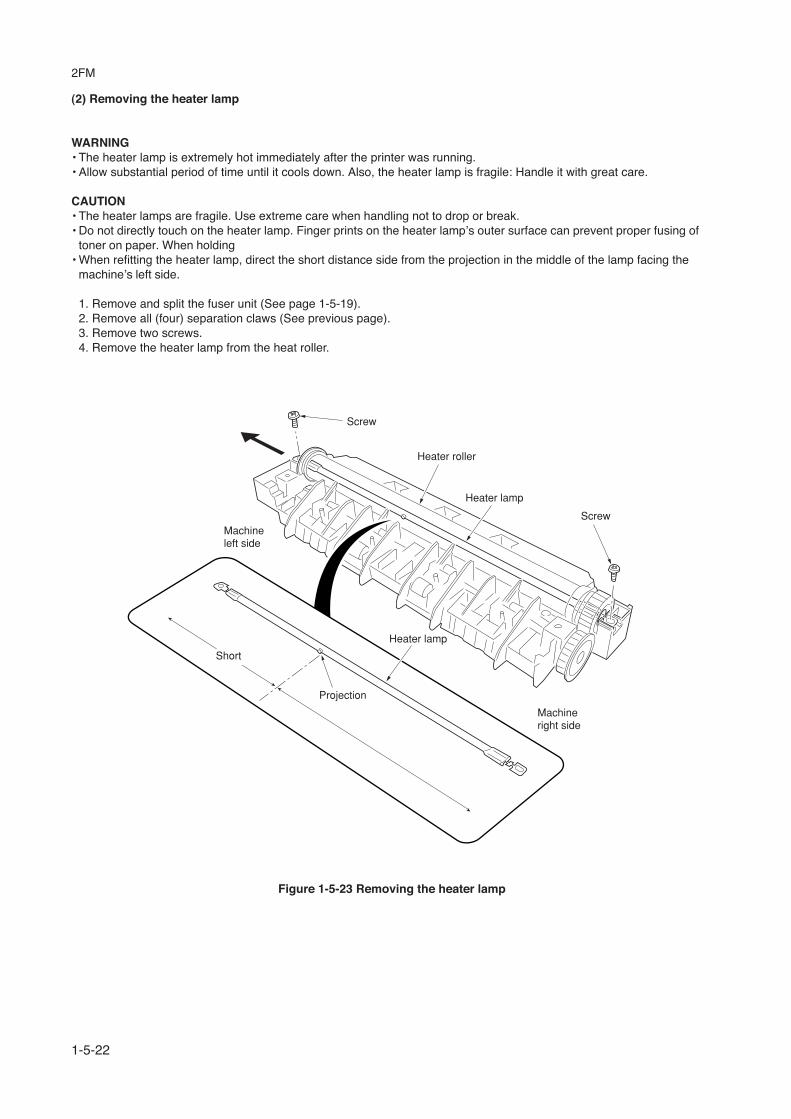
(2) Removing the heater lamp
WARNING• The heater lamp is extremely hot immediately after the printer was running.• Allow substantial period of time until it cools down. Also, the heater lamp is fragile: Handle it with great care.
CAUTION• The heater lamps are fragile. Use extreme care when handling not to drop or break.• Do not directly touch on the heater lamp. Finger prints on the heater lamp’s outer surface can prevent proper fusing of
toner on paper. When holding• When refitting the heater lamp, direct the short distance side from the projection in the middle of the lamp facing the
machine’s left side.
1. Remove and split the fuser unit (See page 1-5-19).2. Remove all (four) separation claws (See previous page).3. Remove two screws.4. Remove the heater lamp from the heat roller.
Figure 1-5-23 Removing the heater lamp
Machineleft side
Screw
Heater lamp
Heater roller
Screw
Machineright side
Long
Projection
Short
Heater lamp

2FM
1-5-23
(3) Removing the heat roller
WARNING• The heat roller is extremely hot immediately after the printer was running. Allow substantial period of time until it cools
down.
1. Remove and split the fuser unit (See page 1-5-19).2. Remove the heater lamp (See previous page).3. Press the lamp A holder away from the heat roller. Pull up both heat R bush and heat L bush at the same time.
Figure 1-5-24 Removing the heat R bush and heat L bush
Heat L bush
Heat roller
Heat R bush

2FM
1-5-24
4. Remove the heat gear Z33, heat R bush, and heat L bush from the heat roller.
Figure 1-5-25 Removing the heat roller
Heat gear Z33
Heat L bush
Heat roller
Heat R bush

2FM
1-5-25
(4) Removing the fuser thermistor1. Remove and split the fuser unit (See page 1-5-19).2. Remove the heater lamp (See page 1-5-22).3. Remove the heat roller (See page 1-5-23).4. Remove one screw.5. Remove the fuser thermistor.
Figure 1-5-26 Removing the fuser thermistor
Screw
Fuser thermistor

2FM
1-5-26
(5) Removing the thermal cutout
CAUTION• Do not bend the terminals of the thermal cutout.
1. Remove and split the fuser unit (See page 1-5-19).2. Remove the heater lamp (See page 1-5-22).3. Remove the heat roller (See page 1-5-23).4. Remove the two screws.5. Remove the thermal cutout.
Figure 1-5-27 Removing the thermal cutout
Thermal cutout
Screws

2FM
1-5-27
(6) Removing the press roller
WARNING• The press roller is extremely hot immediately after the printer was running. Allow substantial period of time until it cools
down.
1. Remove and split the fuser unit (See page 1-5-19).2. Remove the press roller from the fuser unit.
Press roller
Fuser unit
Figure 1-5-28 Removing the press roller

2FM
1-5-28
Screws
Screw
Screw
Connectors
LSU shield
1
3
2
4
1-5-10 Removing the laser scanner unit and the eraser lamp
1. Remove the right cover and left cover (Seepage 1-5-4).
2. Remove four connectors.3. Remove six screws and then remove the LSU
shield.* When refitting the LSU shield, tighten a
screw in order of 4 from 1.
Figure 1-5-29 Removing the LSU shield

2FM
1-5-29
4. Remove three screws.5. Remove two connectors from the laser
scanner unit.6. Remove the laser scanner unit.
* When refitting the laser scanner unit, tightena screw in order of 3 from 1.
Screws
Conncetor
Laser scanner unit
Conncetor
1
2
3
Figure 1-5-30 Removing the laser scanner unit

2FM
1-5-30
Eraser lamp
7. Remove the eraser lamp.
1-5-31 Removing the eraser lamp

2FM
1-5-31
A
B
Snap
Snaps
Main charger cap
C
Main chargerunit
Main charger unit
Terminal
1-5-11 Removing the main charger unit
1. Remove the process unit from the printer (See page 1-5-2).2. Unlatch the three snaps, and remove the main charger cap.3. Draw the main charger unit in the direction of arrow A, then pull it out in the direction of arrow B.
Figure 1-5-32 Removing the main charger unit
CAUTION• When refitting the main charger unit, hold terminal down C, then push frontwards. Use care not to deform the terminal.

2FM
1-6-1
Figure 1-6-1 Firmware program data format
1-6-1 Upgrading the firmware on the main board
Updating the system (controller) firmware is possible by downloading the firmware through the parallel interface or throughthe memory card (CompactFlash). These firmware programs are directly overwritten in the system DIMM [KP-1050] (FlashROM type only) on the main board. The operator panel message in different languages can also be downloaded through theparallel interface or through the memory card.
(1) Firmware program data formatKyocera supplies the following types of data for updating firmware of the different purposes:• System firmwareThe data to be downloaded are supplied in the following format:
B11K8000.bcmp
Boot program is included.
ID code for Kyocera mita
Machine code:FS-1020D (B11)
compression
Version code: Version 80.00
System firmware file name example

2FM
1-6-2
(2) Downloading the firmware from the parallel interface
This section explains how to download firmware data from the parallel interface. The printer system can automaticallyrecognize whether the data to be overwritten is for controller firmware.
CAUTIONDownloading the firmware takes several
minutes. Do not turn power off duringdownloading.
NOTEMS-DOS is required for a downloading from
the parallel interface. The computer must beconnected to the printer with a parallelcable.
Procedure 1. Turn printer power on. Make sure the printer is
ready. 2. At the DOS prompt, send the following
command to the printer:
echo !R! UPGR "SYS";EXIT;>prn
3. Confirm that downloading was finishednormally by the LED indicator. (See page 1-6-4)
4. Turn power off. 5. Turn power on again. Check the printer gets
ready.Confirm the status page shows the new
firmware version (See service informationon the status page). If downloading fails, theprinter indicates an error display using theLED indicators. To identify error, refer to thetable on page 1-6-4.

2FM
1-6-3
(3) Downloading the firmware from the memory card
To download data written in a memory card (CompactFlash) to the printer, proceed as explained in this section.
CAUTIONDownloading firmware takes several minutes.
Do not turn power off during downloading. Ifdownloading is interrupted by an accidentalpower failure, etc., the system DIMM mayhave to be replaced.
NOTEThe firmware program data must be stored to
the root directory of the memory card.
Procedure 1. Turn power switch off. 2. Remove the two screws and then remove the
slot cover. Insert the memory card in theprinter’s memory card slot.
3. Turn power switch on. 4. The printers starts and finishes downloading
automatically. 5. Confirm that downloading was finished
normally by the LED indicator. (See page 1-6-4)
6. Turn power off. 7. Remove the memory card and then secure the
slot cover by using two screws. 8. Turn power on again. Check the printer gets
ready. 9. Turn power on again. Check the printer gets
ready.Confirm the status page shows the new
firmware version (See service informationon the statuspage). If downloading fails, theprinter indicates an error display using theLED indicators. To identify error, refer to thetable on page 1-6-4.
Figure 1-6-1
Memory card
Slot cover
Screws

2FM
1-6-4
(4) Downloading errors
The following downloading errors are indicated on LED indicators when an error occurred during downloading the firmwaredata.
Cause Corrective actionDescriptionLED indicatorsLED indicators
Download finished normally
Convention
Download errors
Slow flashing
Fast flashing
Lit
Off
Red Green Meaning
Download data error
Deficit of a file header
Deficit of a data header
File checksum error
File header version error
Data header version error
System download error
Download receiving error
Replace parallel cable.
Improper connection of parallel cable between PC and printer
Check the contact between PC and printer’s interface connector.
Confirm whether the firmware conforms to this printer.
Replace the system DIMMboard.
Defective system DIMM board
Defective parallel cable
Incompatibility of firmware and system DIMM board
Obtain normal firmware.
If the corrective action above does not solve the problem, replace engine board (KP-1046). See page 1-5-9.

2FM
2-1-1
2-1-1 Paper feeding system
The paper feeding system picks up paper from the cassette, MP tray, or if installed, the paper feeder, feeds it in thecopier, and delivers in the output tray. Paper is fed at the precise timing in synchronization with data processing. Thepaper feeding system finally delivers the printed page to either the face-down or face-up tray as manipulated by the user.
The figure below shows the components in the paper feeding system and the paths through which the paper travels. Thesensors, clutches, etc., are described in the following pages.
Figure 2-1-1 Paper feeding path
1
2
3*
^
%
#
& @
$ 6 79!99
0
8
4
1 Cassette2 MP tray3 Face-down output tray4 Process unit5 Fuser unit6 Feed roller7 Feed pulley8 MP feed roller9 Lower registration roller
0 Upper registration roller! Transfer roller@ Drum# Heat roller$ Press roller% Lower exit roller^ Exit pulley& Upper exit roller* Exit pulley

2FM
2-1-2
(1) Paper feed controlThe following diagram shows interconnectivity of the feeding system components including the sensors and rollers. Theengine board provides the signals in conjunction with the electrophotography process that is driven by the main board.
Figure 2-1-2 Paper feed control
MRDYNYC04-8YC04-9
YC04-1
YC14-2
CN1-8CN1-9
CN1-1CN2-2
DUDR1
RESDRN
RESITYC303-6
CN2-10 CN302-7
YC11-8
YC13-1YC13-3
YC03-2
YC12-10EXITN
Engine board
Bias board
High voltageboard
Switchbacksolenoid
Registrationclutch
MPFSOLYC09-2
MP feedclutch
MP papersensor
HANDSNYC07-2
FEDDRN
FEDDRN
Feedclutch
Main motor
Papersensor
PAPER
Registrationsensor
Powersupply board
Exitsensor
DUDR2
MOTORN

2FM
2-1-3
(2) Paper feeding mechanism
Figure 2-1-3 Paper feeding mechanism
A For process unit; drum (From main unit)B For process unit; toner container, developing roller etc. (From main unit)C From process unit; drum (To transfer roller)
Driving power train
C
A
B

2FM
2-1-4
2-1-3 Electrophotographic system
Electrophotography is the technology used in laser printing which transfer data representing texts or graphics objectsinto a visible image which is developed on the photosensitive drum, finally fusing on paper, using light beam generatedby a laser diode.
This section provides technical details on the copier’s electrophotography system.
(1) Electrophotographic cycleThe electrophotography system of the copier performs a cyclic action made of six steps as follows. Each step istechnically explained in the following sections.
Figure 2-1-4 Electrophotographic cycle
The sections for main charging, exposure (drum), developing, and cleaning are modularized in one Process unit.
2 Exposure
3 Developing6 Cleaning
1 Main charging
4 Transfer
5 Fusing
Process unit
Fuser unit
Laser scaner unit
Drum

2FM
2-1-5
(1-1) Process unit mechanism
Figure 2-1-5 Process unit mechanism
1
‹
*
%4
5
6
7
890^&
#
$
D
A
B
C
23)
(
⁄¤
@
!
Driving power train
A For drum (From main unit)B For toner container, developing roller, etc. (From main unit)C For main unit (Transfer roller)D For toner container
1 Main charger unit2 Charger wire3 Grid4 Developing roller5 Gear Z14-Z186 Gear Z14-Z367 Gear Z18-Z368 Free gear Z409 Gear Z18-Z35H0 MAG gear Z24H! Mixer gear Z20 B@ Mixer gear Z20 A
# DLP screw B$ DLP screw A% Drum^ Drum gear Z35H& Drum shaft* Drum gear Z36( Sweep gear Z13) Idle gear 18H⁄ Cleaning blade¤ Sweep roller‹ Waste toner reservoir

2FM
2-1-6
(2) Main charging
(2-1) Photo conductive drumThe durable layer of organic photoconductor (OPC) is coated over the aluminum cylinder base. The OPC tend to reduceits own electrical conductance when exposed to light. After a cyclic process of charging, exposure, and development,the electrostatic image is constituted over the OPC layer.Since the OPC is materialized by resin, it is susceptible to damage caused by sharp edges such as a screwdriver, etc.,resulting in a print quality problem. Also, finger prints can cause deterioration of the OPC layer, therefore, the drum (inthe process unit) must be handled with care. Substances like water, alcohol, organic solvent, etc., should be strictlyavoided.As with all other OPC drums, the exposure to a strong light source for a prolonged period can cause a print qualityproblem. The limit is approximately 500 lux for less than five minutes. If the drum (process unit) remains removed formthe copier, it should be stored in a cool, dark place.
Figure 2-1-6 Photo conductive drum
Aluminum base cylinder
Photo conductive layer

2FM
2-1-7
(2-2) Charging the drumThe following shows a simplified diagram of the electrophotographic components in relation to the engine system.Charging the drum is done by the main charger unit A.
Figure 2-1-7 Charging the drum
As the drum C rotates in a “clean (neutral)” state, its photoconductive layer is given a uniform, positive (+) coronacharge dispersed by the main charger wire B.
Due to high-voltage scorotron charging, the charging wire can get contaminated by oxidization after a long run.Therefore, it must be cleaned periodically from time to time. Cleaning the charging wire prevents print quality problemssuch as black streaks.
C
B
A
MHVDR1MHVDR
Main charging output
Zenerboard
KP-5159
Bias board
High voltage board
YC-M CN2-A4MHVDR2PSEL2
CN2-A9
Engine board
YC11-5
YC12-9

2FM
2-1-8
(3) ExposureThe charged surface of the drum A is then scanned by the laser beam from the laser scanner unit B.
Figure 2-1-8 Exposure
The laser beam (780 nm wavelength) beam is dispersed as the polygon motor (polygon mirrors) revolves to reflect thelaser beam over the drum. Various lenses and mirror are housed in the scanner unit, adjust the diameter of the laserbeam, and focalize it at the drum surface.
A
Laser beam(LSU)

2FM
2-1-9
(3-1) Laser scanner unit
2
1
Diversion mirror
654
3
1 Laser diode ................................................... Emits diffused, visible laser.2 Cylindrical lens .............................................. Compensates the vertical angle at which the laser beam hits a polygon
mirror segment.3 Polygon mirror (motor) .................................. Has six mirror segments around its hexagonal circumference; each
mirror corresponding to one scanned line width on the drum when laserbeam scans on it.
4 F-theta lens ................................................... The f-theta lens equalizes focusing distortion on the far ends of thedrum.
5 Sensor mirror ................................................ Bends the very first shot of a laser scan towards the beam detectionsensor (6).
6 Pin photo sensor ........................................... When shone by the sensor mirror above, this photo-sensor generates a trigger signal for the engine controller to start activating the paperfeeding system.
Figure 2-1-9 Laser scanner unit

2FM
2-1-10
(3-2) Drum surface potentialThe laser beam is continually switched on and off depending on the print data. It is on for a black (exposed) dot and offfor a white (blank) dot. Since the drum surface is evenly charged, whenever it is illuminated by the laser beam, theelectrical resistance of the photoconductor is reduced and the potential on the photoconductor is also lowered. Resultedon the drum surface is an electrostatic image which represents the data to print. Note that the area to be printed blackhas the low potential, constituting a “positively exposed” image.
Figure 2-1-10 Drum surface potential
Aluminumcylinder
OPClayer
Laser beam
Charged surface potential+400±15 V
Exposed surface potentialapproximately +60 to +80 V
Drum

2FM
2-1-11
(4) DevelopmentThe latent image constituted on the drum is developed into a visible image. The developing roller A contains a 3-pole(S-N-S) magnet core B and an aluminum cylinder rotating around the magnet core B. Toner attracts to the developingroller A since it is powdery ink made of black resin bound to iron particles. Doctor blade C, magnetized by magnet D,is positioned approximately 0.3 mm above the developing roller A to constitute a smooth layer of toner in accordancewith the roller revolution.
Figure 2-1-11 Development
The developing roller A is applied with the AC-weighted, positive DC power source. Toner E on the developing roller Ais given a positive charge. The positively charged toner E is then attracted to the areas of the drum F which wasexposed to the laser light. (The gap between the drum F and the developing roller A is approximately 0.3 mm.) Thenon-exposed areas of the drum F repel the positively charged toner as these areas maintain the positive charge.The developing roller A is also AC-biased to ensure contrast in yielding by compensating the toner’s attraction andrepelling action during development.
HVCLK
Bias board
YC-B
Engine board
YC7-7YC302-10
NS
N
S
S
0.3 - 0.4 mm
0.1 mm
Magnetism
Developingbias output275±5 V DC + AC
A B
F
E
DC

2FM
2-1-12
(5) TransferThe image developed by toner on the drum A is transferred onto the paper because of the electrical attraction betweenthe toner itself and the transfer roller B. The transfer roller is negatively biased so that the positively charged toner isattracted onto the paper while it is pinched by the drum and the transfer roller.
Figure 2-1-12 Transfer
The nominal transfer bias is set to approximately -1.8 kV (limit) with the -6 mA current. Since the ideal potential of thetransfer bias depends on the thickness of paper, the bias is raised to approximately -2.5 kV/-6 mA for thicker paper. Onthe other hand, the bias current is reduced to -1.8 kV/-6 mA for thin paper.
A
B
High voltage board
HVISELTHVDR
PSEL1
Transfer bias
Bias board
CN2-A7CN2-A5
RTHVDRCN2-A6
CN2-A8YC-T
Engine board
YC12-11YC12-14YC11-2YC12-16

2FM
2-1-13
(6) FusingThe toner on the paper is molten and pressed into the paper as it passes between the heat roller A and the press rollerB in the fuser unit.
Figure 2-1-13 Fusing
The heat roller has a halogen lamp inside which continuously turns on and off by the thermistor to maintain the constanttemperature onto the heat roller surface.The heat roller is resin coated by florin to prevent toner from accumulating on the roller after a long run. Care must betaken while handling the heat roller not to scratch the roller surface as doing so may result in print problems.The heat roller has four claws which are continuously in contact with its surface. These claws prevent the paper on whichtoner has been fused from being wound around the heat roller causing paper jam.
The pressure roller is made of the heat-resistant silicon rubber. This roller is used to strongly press the paper towards theheat roller by means of coil springs.The temperature of the heat roller is constantly monitored by the engine board using the thermistor and triac. Should thetemperature of the heat roller exceed the predetermined value, the thermal cutout is activated to effectively disconnectthe heater (halogen) lamp from power.
A
B

2FM
2-1-14
(6-1) Fuser unit mechanism
Figure 2-1-14 Fuser unit mechanism
6
5
4
3
2
1
!
@
8
09
7
1 Heat roller2 Idle gear Z343 Exit gear Z234 Idle gear Z185 Heat gear Z336 Press roller
7 Heater lamp8 Thermal cutout9 Separator(s)0 Thermistor! Exit pulley(s)@ Lower exit roller

2FM
2-1-15
(7) CleaningAfter the transferring process, the drum needs to be physically cleaned of toner which is residual after the developmentprocess. The cleaning blade A is constantly pressed against the drum B and scrapes the residual toner off to thesweep roller C. The waste toner is collected at the output end of the sweep roller C and sent back to the tonercontainer, into the waste toner reservoir D.
Figure 2-1-15 Drum cleaning and erasing static charge
After the drum B is physically cleaned, it then must be cleaned to the electrically neutral state. This is necessary toerase any residual positive charge, ready to accept the uniform charge for the next print process. The residual charge iscanceled by exposing the drum B to the light emitted from the eraser lamp E. This lowers the electrical conductivity ofthe drum surface making the residual charge on the drum surface escape to the ground.
A
C
B
E
D

2FM
2-2-1
2-2-1 Electrical parts layout
(1) Electrical parts layout
1 Main board (KP-1050)2 Engine board (KP-1046)3 Power supply board4 High voltage board5 Bias board (KP-1051)6 Toner sensor [PWB] (KP-5055)7 Waste toner sensor [PWB] (KP-5155)8 Eraser lamp [PWB] (KP-5157)9 Registration sensor0 Paper sensor! MP paper sensor@ Exit sensor# Interlock switch$ Cassette switch
Figure 2-2-1 Electrical parts layout
2
—
¤
)
$
59
!0
6
4
›
8 7
%
&
fi
@
^
‡
3
(
#
⁄
fl
*
1
‹
% Power switch Temperature thermistor
& Fuser thermistor* Thermal cutout( Main motor) Cooling fan⁄ Registration clutch¤ Feed clutch‹ MP feed clutch› Switchback solenoidfi Laser scanner unitfl Heater lamp‡ Paper feeder interface connector— AC Inlet
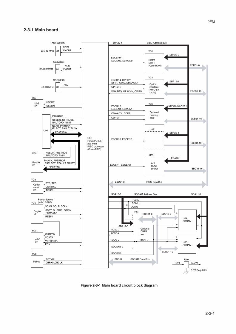
2FM
2-3-1
2-3-1 Main board
Figure 2-3-1 Main board circuit block diagram
Xtal(System)
CXIN
33.333 MHz CXOUT
VXOUTX237.6687MHz
Xtal(video)
X348.000MHzUXIN
OSC(USB)
DBTXDDebug
YC8
SBSY, SI, SDIR, EGIRNPDMASKN
SCKN, SO, PLGCLK
YC6
RESIN
EngineI/F
Power Source[+5V, SGND]
YC7
PDN
VDATAOUTPEN
APCI/F
DTR, TXD
DSR,RXDRSSEL
YC5
OptionserialI/F
NSELIN, PNSTROBNAUTOFD, PNINI
PNACK, PPERROR,PSELECT, PFAULT PBUSY
PPDATA8
YC4
ParallelI/F
PDATA7-0
NACK, PERROR,SELECT, FAULT, BUSY
U06
NSELIN, NSTROBE,NAUTOFD, NINIT
U01PowerPC405266 MHzRISC processor(Core+ASIC)
EBCSN0-1,EBOEN0, EBWEN0
EBA22-1
DIMMSlot-1(Core ROM)
YS1
EBA22-2
EBD31-0
EBD31-16
EBA22-1
EBA22, EBA10-1
EBA20-1
EBD31-16
EDB31-16
EBD31-16
YC1
YC2
Optionalmemorycard
EBCSN0, EBOEN2
EBCSN2, EBOEN1, EBWEN1
CDRST
CDWAITN, CDET
EBCSN4, OPRDY, IORN, IOWN, DMAACKN
DMAREQ, OPACKN, OPIRN
OPRSTNOptinalinterfaceKUIO-LV(3.3V)
EBCSN1, EBOEN2APIROMsocket
EBIU Data BusEBD31-0
SDRAM Address Bus SDA11-0SDA12-0
OptionalDIMMslot
SDD31-0
SDA12-0
SDD15-0
RASN
IICSCL
IICSDA
DQMU
DQML
+5V1 +3.3V1U10SDRAM Data BusSDD31
SDCSN0
SDCSN1-2
U04SDRAM
U05SDRAM
SDCLK
SDD31-16
3.3V Regulator
YS2
SDCLK
EBIU Address Bus
EBA15-1
U02
U03
DBRXD,DBCLK
VDFONSPL
P1284DIR
YC3
USBDP
USBDNUSBI/F
VXIN
X1

2FM
2-3-2
2-3-2 Engine board
Figure 2-3-2 Engine board circuit block diagram
LED indicators(DL1, DL2, DL3, DL4
Main board
Switchbacksolenoid
Waste toner
sensorEraserlamp
LSU
Registrationclutch
MP feedclutch
EEPROM(U2)
Bias board
Main motor
Temperaturethermistor
(TH1)
Reset IC(U5)
Engine board
Papersensor
MP papersensor
CPU(U1)
Key switches(SW1, SW2)

2FM
2-3-3
(1) Eraser lamp control circuitThe CPU (U1) turns pin #23 (ERASER) of U1 to H level, transistors (Q14) turns on consequently, and the 24 V DC given atpin #1 of connector YC5 applies to the eraser lamps. The eraser lamps thus illuminate as the current flows through theresistors (R109, R110, and R111), eraser lamp, the pin #2 of connector YC5, transistor Q14 and the ground.
GND
PGND
123
2
3
1
Q14
R69 R70 R71
ERASER
+24V3
YC14
ERASPW
Eraser lamp
P25/ASCK023
CPUU1
ERASER
Engine board
Eraser lamp cotrol circuit
Figure 2-3-3 Eraser lamp control circuit

2FM
2-3-4
(2) Heater lamp control circuitActivation of the heater lamp is dominated by the HEAT signal which is derived by the engine CPU (U1) at its pin #1. Whenits level is high, transistor Q10 turns on, photo-triac PC2 and triac TRA1 turn on simultaneously, and the heater lamp isapplied with the primary AC voltage in turn.Switching of triac TRA1, as affected by the HEAT signal is made in synchronization with the zero-cross signal ZCROSSwhich is generated by the power supply unit. The zero-cross signal detector watches the transition of alternating plus andnegative current and detects the zero crosses. This detector derives the resultant ZCROSS signal at its pin #43 of theengine CPU (U1). Since abrupt change in the current flow can be significantly avoided by synchronizing triac TRCA with thezero-cross signal, the possibility of noise due to the primary AC supply is greatly reduced.CPU (U1) selectively switches among those variations for applying voltages to the heater lamp according to the THERMsignal which appears at pin #33 as feedback.A fraction of THERM is applied to pin #2 of comparator U4-1. The comparator maintains comparison of the potential at pin#2 and pin #3 which gives a reference for the possible anomaly in the heater temperature (bred by resistors R44 and R40).Should the voltage at pin #2 exceed that at pin #33, the level at pin #1 becomes low. Since pin #1 is wired (via transistorarray QA4) to the output line for the HEAT signal, the HEAT signal is enforced to be low regardless the behavior of CPU(U1), thus preventing possible heat overrun.
HEAT
ZCROSS
23
1
GND
GND GND
+5V
+5V
GND
R44
R40
+−393
U4-1
THERMA33P10/ANI0
P50/A8
P00/INTP0
1
43
CPUU1
Power supply unitBias board
Engine board
High voltage board
HEATN
ZCROSS
Heat roller
Thermal cutout
Heater lamp
Fuser thermistor
AC input
Triac(TRA1)
Zero crosssignal
detectioncircuit
QA4
Q10
+24 V
Heater lamp control circuit
(PC2)Photo-triac
Figure 2-3-4 Heater lamp control circuit

2FM
2-3-5
(3) Polygon motor control circuitThe main board supplies the 2598.4 Hz clock pulse (PLGCLK) via the engine board to the PLL control IC (IC1) for thepolygon motor. To begin printing, the engine CPU U1 turns PLGDR to H level, the PLL control IC (IC1) starts to revolve thepolygon motor so that the revolution is 25,984 rpm which depends on the PLGCLK clock pulse. When PLL control IC (IC1)finds that the polygon motor is revolving at the rated speed, turns PLGDRN to L level to acknowledge the engine CPU thatthe rated speed has been achieved. On the contrary, if PLGRDYN does not turn to L level within 8 seconds since PLGDRN has been L level.
Figure 2-3-5 Polygon motor control circuit
GND
2
3
1Q7
Q9
+5V +
PGND
PGND
+24V3
+24V3PGNDPLGDRNPLGRDYNPLGCLK
YC6
5
4
3
2
1
PLGRDYN
MRDYNPLGMRDY
2598.4Hz
PLGDR
PLGCLK
CPUU1
Polygon motor
PLL control IC
(IC1)
25,984 rpm
Engine board
Main board
Main motor
Polygon motor control circuitLaser scanner unit
GND
QA7

2FM
2-3-6
2-3-3 Power supply board
The power supply board provides the AC power input and DC power and outputs. The high voltage bias generator circuit ismounted on a separate board. A simplified schematic diagram is shown below.
Figure 2-3-6 Power supply board circuit block diagram
FET(Q1)
Switching/Overcurrentdetectioncircuit
Powerswitch
Currentfuse
Currentfuse
Noisefiltercircuit(L1)
Transformer(T1)
24 V DCrectifier/smooth-ing circuit
24 V DCshutoffcircuit
Over voltagedetectioncircuit
Photo-coupler(PC1)
Photo-coupler(PC5)
Photo-Triac(PC2)
Triac(TRA1)
Heaterlamp
ACinput
5 V DCrectifier/smooth-ing circuit
Fuserthermistor
Cooling fan
+24V1
+24V2
+24V1
THERM
HEATN
EXITN
PGND, SGND
+5 V
FAN
SLEEP
Thermalcutout
Transistor(Q121)
ZCROSSPhoto-coupler(PC4)
(SW1) (F1)
(F2)
Exitsensor(PC3)
Zero cross signaldetection circuit
Power supply unit
C5
D1
+

2FM
2-3-7
2-3-4 Bias board
The bias board contains the developing bias output circuit, registration sensor, and the cassette switch. It also provides aliaison connection to the high voltage board, power supply, and the toner sensor.
Figure 2-3-7 Bias board circuit block diagram
Developingroller
Bias board
Regist-rationsensor
Developing biasoutput circuit
FAN1
FAN FAN2
SWIN
RESIT
TONER
HVCLK
RTHVDR, HVISELMHVDR1, MHVD2 PSEL1, THVDR
EXTIN, THERM
Casetteswitch
+5V
TONERTonersensor
275 V DC + AC
+5V
+5V
+5V
+24V3+24V2+24V2
Inter-lockswitch
+24V2
+24V1
SLEEPSLEEP
+24V3+24V3
HEATN
ZCROSS
HEATN
High voltageboard
Power supplyboard
+5V
+24V2
+24V2
(Q305,Q206)
ZCROSS
EXTIN, THERM
Engine board

2FM
2-3-8
2-3-5 High voltage board
The high voltage board contains the high voltage output circuit, interlock switch circuit as well as providing a liaisonconnection with the power supply board, bias board, and the engine board.
Figure 2-3-8 High voltage board circuit block diagram
MHVDR1
MHVDR2
THVDRRTHVDR
+24V2+24V2+24V2
+24V3
+24V3
+24V1
+5VTHERM, EXITN
ZCROSS
Interlock switch
High voltage boardBias board
Power supply board
Engine board
FAN, HEATN
SLEEP
Main highvoltage controlcircuit(IC1)
PSEL1HVSEL
Main highvoltage controlcircuit(IC51)
Main charger
Transfer roller

2FM
2-3-9
(1) Interlock switchThe interlock switch is located on the high voltage board and opened and closed in conjunction with the front cover or thefront top cover via the interlock lever. This switch connects and disconnects the +24 V DC power supply line. If the frontcover or the front top cover is open, the interlock switch is open, and the +24 V DC to the high voltage output circuit, biasboard, engine board, and the power supply board is disconnected, deactivating the high voltage output, laser output, mainmotor output for safety. The cooling fan is an exception: Since the cooling fan is directly fed with +24 V DC from the powersupply unit at the primary side (+24V1) of the interlock switch, the cooling fan is not deactivated even the cover is open.
High voltage board
Power supply unit
Interlock switch
Interlock lever
Projection
Projection
Front top cover
Machine left side view
+24V1+24V1
+24V2
+24 V DCoutput
+24V2
+24
V3
+24
V2
High voltage output circuit
Bias board
Cooling fan
Triac, etc.
Front cover
Engine board
Figure 2-3-9 Interlock switch
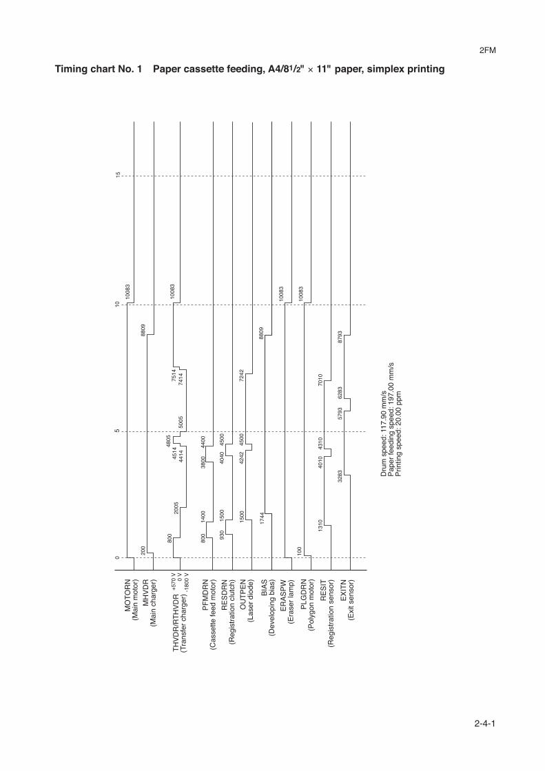
2FM
2-4-1
Timing chart No. 1 Paper cassette feeding, A4/81/2" × 11" paper, simplex printing
010
5
100
1310
800
1400
1500
200
4010
4310
7010
3800
4400
930
4040
4500
3283
5793
6283
8793
1008
3
1008
3
1008
3
8809
1744
8809
1500
4500
4242
7242
800
+57
0 V
0 V
-180
0 V
2005
4414
4805
1008
375
1450
0545
1474
14
Dru
m s
peed
: 117
.90
mm
/sP
aper
feed
ing
spee
d: 1
97.0
0 m
m/s
Prin
ting
spee
d: 2
0.00
ppm
15
MO
TO
RN
(Mai
n m
otor
)
MH
VD
R(M
ain
char
ger)
TH
VD
R/R
TH
VD
R(T
rans
fer
char
ger)
PF
MD
RN
(Cas
sette
feed
mot
or)
RE
SD
RN
(Reg
istr
atio
n cl
utch
)
OU
TP
EN
(Las
er d
iode
)
BIA
S(D
evel
opin
g bi
as)
ER
AS
PW
(Era
ser
lam
p)
PLG
DR
N(P
olyg
on m
otor
)
RE
SIT
(Reg
istr
atio
n se
nsor
)
EX
ITN
(Exi
t sen
sor)

2FM
2-4-2
Timing chart No. 2 Paper cassette feeding, A4/81/2" × 11" paper, duplex printing
010
515
20
100
1310
800
1400
1500
200
4010
9110
930
5580
9300
3283
5793
1744
1360
9
1500
9300
4242
1204
2
800
2005
4414
1232
949
1412
229
1138
313
893
1517
3
1517
3
1517
3
1517
3
1360
9
9300
9746
6073
6273
8573
8773
Dru
m s
peed
: 117
.90
mm
/sP
aper
feed
ing
spee
d: 1
97.0
0 m
m/s
Prin
ting
spee
d: 1
0.30
ppm
+57
0 V
0 V
-180
0 V
MO
TO
RN
(Mai
n m
otor
)
MH
VD
R(M
ain
char
ger)
TH
VD
R/R
TH
VD
R(T
rans
fer
char
ger) PF
MD
RN
(Cas
sette
feed
mot
or)
RE
SD
RN
(Reg
istr
atio
n cl
utch
)O
UT
PE
N(L
aser
dio
de)
BIA
S(D
evel
opin
g bi
as)
ER
AS
PW
(Era
ser
lam
p)P
LGD
RN
(Pol
ygon
mot
or)
RE
SIT
(Reg
istr
atio
n se
nsor
)
DU
DR
1(S
witc
hbac
k so
leno
id)
DU
DR
2(S
witc
hbac
k so
leno
id)
EX
ITN
(Exi
t sen
sor)

2FM
2-4-3
Wiring diagram
SGNDSAMPLENVDATANOUTPENSGND+5VSGNDPDN
Hig
h vo
ltage
boa
rd
YC
-T
YC
-M
CN
1
CN
2
YC
-B
YC
-304
12345678
12345678
2FM2608
YC
7
YC
6
YC
2
YC
5
YC
1
Mai
n bo
ard
KP
-105
0Y
C3
YC
4
SG
ND
+5V
+5V
+5V
OU
TP
EN
SG
ND
PLG
CLK
EG
SO
SC
KN
EG
SI
PD
MA
SK
N
SB
SY
S
DIR
E
GIR
N
SG
ND
R
ST
N
2FM
2602
YC
01
FE
DD
RN
PF
SE
NP
FP
FP
ER
PF
CLK
PF
MD
RN
PG
ND
+5V
MR
DY
NM
OT
OR
N+
24V
3
2DC
2711
YC
04
YC
14
CN
1C
N2
CN
3
+24V3PGNDPFMDRNPFCLKPFPFPERPFSEN
+24V3PGNDPFMDRNPFCLKPFPFPERPFSEN
2A82759
YC
802
Fer
rite
core
YC
801
OUT1OUT2OUT3OUT4
PF
feed
mot
or
DU
DR
1C
OM
MO
ND
UD
R2
+24
V3
RE
SD
RN
ER
AS
PW
ER
AS
ER
+24
V3
+24
V3
PG
ND
PG
ND
SW
INR
ES
ITT
ON
ER
+24
V2
MH
VD
R1
FAN
2FA
N1
TH
VD
RT
HE
RM
2FM
2601
YC
30
YC
30
YC
11
YC
13
YC
03
YC
05
YC
12R
TH
VD
RH
EA
TN
HV
ISE
L+
5VS
LEE
PP
SE
L1E
XIT
NM
HV
DR
2Z
CR
OS
SH
VC
LK+
5V+
5V+
5VS
GN
DS
GN
DS
GN
D
PLG
CLK
PLG
RD
YN
PLG
DR
NP
GN
D+
24V
3
Eng
ine
boar
dK
P-1
046
+5V
TN
FU
LLG
ND
YC
06
YC
10
Lase
r sc
anne
r un
it
TRANSFER ROLLER
Zen
ner
boar
dK
P-5
159
12345678
12345678
1 2 3 4 5
1 2 3 4 5
1 2 3 4 5
1 2 3 4 5
1 2 3 4 5 6 7 8 9 10 11 12 13
1 2 3 4 5 6 7 8 9 10 11 12 13
13 12 11 10 9 8 7 6 5 4 3 2 1
13 12 11 10 9 8 7 6 5 4 3 2 1
Bia
s bo
ard
KP
-105
11 2
1 2
Sw
itchb
ack
sole
noid
Reg
istr
atio
ncl
utch
+24
V3
MP
FS
OL
YC
09
1 21 2
MP
feed
clut
ch
MP
pap
erse
nsor
1 21 2
+5V
HA
ND
SN
GN
D
2A82
758
YC
07
1 2 3
1 2 3
1 2 3
Was
teTo
ner
sens
orK
P-5
155
1 2 3
1 2 3
1 2 3
1 2 31 2 3 4 5 6 7 8 9 10
1 2 3 4 5 6 7 8 9 10
1 2 3 4 5 6 7 8 9 10
1 2 3 4 5 6 7 8 9 10
12
12
+24V3FEDDRN
123456
123456
123456
123456
123456
123456
123456
123456
1234
1234
1234
DRUM
PF
feed
boa
rdP
WB
KP
-794
Opt
iona
l pap
er fe
eder
PF
-17
Con
nect
orbo
ard
KP
-796
Option I/FKUIO-LV Parallel
YC
702
YC
701
16 15 14 13 12 11 10 9 8 7 6 5 4 3 2 1
16 15 14 13 12 11 10 9 8 7 6 5 4 3 2 1
16 15 14 13 12 11 10 9 8 7 6 5 4 3 2 1
16 15 14 13 12 11 10 9 8 7 6 5 4 3 2 1
2DC
2714
Fee
dcl
utch
Mai
n m
otor
F1
: (E
) 25
0 V
/8 A
(U
) 25
0 V
/15
A
F2
: (E
) 25
0 V
Pow
er s
uppl
y bo
ard C
N4
CN
1C
N5
NL
THERM+5V
AC
Hea
ter
lam
p
Fus
erth
erm
isto
r
The
rmal
cut
out
CN
3
12
12
13
13
LN
LN
1 21 2
Inle
t
SW
1+24
V2
+24
V1 In
terlo
cksw
itch
Pow
erS
witc
h
2BM
2792
(E)
2BM
2791
(U)
2BY
2756
(E)
2BY
2757
(U)
2BY
2751
(J)
Coo
ling
Fan
FAN
+24
V1
+5V+5VFAN
PGNDPGND+24V2
THERMHEATNSLEEPEXITN
ZCROSS+24V1+24V1SGNDSGND
A1/
B1
A2/
B2
A3/
B3
A4/
B4
A5/
B5
A6/
B6
A7/
B7
A8/
B8
A9/
B9
A10
/B10
A11
/B11
A12
/B12
A1/
B1
A2/
B2
A3/
B3
A4/
B4
A5/
B5
A6/
B6
A7/
B7
A8/
B8
A9/
B9
A10
/B10
A11
/B11
A12
/B12
+24
V2/
+24
V2
PG
ND
/PG
ND
+24
V3/
+24
V3
MH
VD
R/F
AN
TH
VD
R/T
HE
RM
RT
HV
DR
/HE
AT
NH
VIS
EL/
SLE
EP
PS
EL1
/EX
ITN
PS
EL2
/ZC
RO
SS
+5V
/+5V
SG
ND
/+5V
SG
ND
/SG
ND
+24
V2
+24
V3
24V
Pow
er C
ut o
ffat
sle
ep m
ode
USBI/F
Pap
erse
nsor
1 2 3
+5V
PA
PE
RG
ND
1 2 3
1 2 3
Era
ser
lam
pK
P-5
157
Tone
rS
enso
rK
P-5
155
+5V TONER SGND
123
123
Developing roller
Memory card
Option serial I/F
F1
50V
1A
18P
in
+5V
1 2 3 4 5 6 7 8 9 10 11 12 13 14 15 16
1 2 3 4 5 6 7 8 9 10 11 12 13 14 15 16
16 15 14 13 12 11 10 9 8 7 6 5 4 3 2 1
16 15 14 13 12 11 10 9 8 7 6 5 4 3 2 1
2FM
2607
123456789
101112131415
123456789
101112131415
Reg
istr
atio
nse
nsor
Tem
para
ture
ther
mis
tor
Cas
sette
switc
h
Exi
tse
nsor

2FM
2-4-4
First occurrence of defect
[63 mm] Developing roller (Process unit)
[25 mm] Upper registration roller
[38 mm] Lower registration roller
[61 mm] Heat roller, Press roller (Fuser unit)
[94 mm] Drum (Process unit)
[50 mm] Transfer roller
Repetitive defects gauge