Embed Size (px)
Citation preview

Santa Clara UniversityScholar Commons
Mechanical Engineering Senior Theses Engineering Senior Theses
6-8-2016
Glows Co Automated Chemical Etching Machinefor Fiber Optic CableMishan GolshanSanta Clara University
Peter LairdSanta Clara University
Thomas OstranderSanta Clara University
Marty WinklerSanta Clara University
Peter SavoySanta Clara University
Follow this and additional works at: https://scholarcommons.scu.edu/mech_senior
Part of the Mechanical Engineering Commons
This Thesis is brought to you for free and open access by the Engineering Senior Theses at Scholar Commons. It has been accepted for inclusion inMechanical Engineering Senior Theses by an authorized administrator of Scholar Commons. For more information, please contact [email protected].
Recommended CitationGolshan, Mishan; Laird, Peter; Ostrander, Thomas; Winkler, Marty; and Savoy, Peter, "Glows Co Automated Chemical EtchingMachine for Fiber Optic Cable" (2016). Mechanical Engineering Senior Theses. 58.https://scholarcommons.scu.edu/mech_senior/58

i
SANTA CLARA UNIVERSITY
Department of Mechanical Engineering
I HEREBY RECOMMEND THAT THE THESIS PREPARED
UNDER MY SUPERVISION BY
Mishan Golshan, Peter Laird, Thomas Ostrander, Martin Winkler, Peter Savoy
ENTITLED
GLOWS CO AUTOMATED CHEMICAL ETCHING
MACHINE FOR FIBER OPTIC CABLE
BE ACCEPTED IN PARTIAL FULFILLMENT OF THE REQUIREMENTS
FOR THE DEGREE OF
BACHELOR OF SCIENCE IN
MECHANICAL ENGINEERING
Robert Marks (Advisor) date
Drazen Fabris (Department Chair) date

ii
GLOWS CO AUTOMATED CHEMICAL ETCHING
MACHINE FOR FIBER OPTIC CABLE
By
Mishan Golshan, Peter Laird, Thomas Ostrander, Marty Winkler, and Peter Savoy
SENIOR DESIGN PROJECT REPORT
Submitted to
the Department of Mechanical Engineering
of
SANTA CLARA UNIVERSITY
in Partial Fulfillment of the Requirements
for the degree of
Bachelor of Science in Mechanical Engineering
Santa Clara, California
Spring 2016

iii
Abstract
This report summarizes the conceptualization and development of an automated machine
designed for a fiber optic cable stripping process used by Lumentum LLC. This process is
currently manually operated by Lumentum’s technicians and involves unavoidable handling of
corrosive chemicals. To increase technician safety, the process will be automated to reduce
chemical - operator interactions. Improving safety conditions for technicians is the primary
motivation for automating this process. Automation will also decrease process variation and
increase product quality. GLOWS CO was tasked with creating this automated solution, leading
to the design of the Automatic Chemical Etching Machine (or A-CHEM) for the fiber etching
process for Lumentum LLC. At the conclusion of this project, the A-CHEM successfully
fulfilled all of the requirements set out by Lumentum, namely improving technician safety and
making the process more ergonomic.

iv
Acknowledgements
We wish to express our sincere gratitude to David Vecht, Senior Mechanical Engineer at
Lumentum, for providing us with the opportunity to work with Lumentum LLC and for his
insights in the design phase for our senior design project.
We sincerely thank our advisor Dr. Marks for streamlining our design process by instigating
critical assessment of overall design as well as individual subsystems. His mastery in material
properties alerted us of crucial design criterion for clean room and caustic environments.
We also wish to thank Mehdi Golshan, Director of Corporate Real Estate and Facilities at
Lumentum LLC, for his clarification of materials used in highly volatile chemical processes.
This led to the expedited selection of vital construction materials necessary for our senior design
project.

v
Table of Contents
Abstract ...................................................................................................................................... iii
Acknowledgements .................................................................................................................... iv
Table of Contents ........................................................................................................................ v
List of Figures .......................................................................................................................... viii
List of Tables ............................................................................................................................. ix
1 Introduction ............................................................................................................................. 1
1.1 Problem Statement ........................................................................................................... 1
1.2 Laser and Fiber Stripping Background ............................................................................ 2
1.3 Automated Manufacturing ............................................................................................... 3
2. Systems-Level ......................................................................................................................... 6
2.1 Current User Scenario ...................................................................................................... 6
2.2 Customer Need ................................................................................................................. 7
2.3 Market Availability .......................................................................................................... 8
2.4 System Level Requirements ........................................................................................... 10
2.5 Core Design Principles ................................................................................................... 11
2.6 Design Principle: Safety ................................................................................................. 11
2.7 Design Principle: Process Repeatability ........................................................................ 12
2.8 Design Principle: Usability ............................................................................................ 14
2.9 GLOWS CO Solution User Scenario ............................................................................. 16
2.10 Design Priorities ......................................................................................................... 17
2.11 Primary Subsystems ................................................................................................... 18
2.12 Project Challenges and Constraints ............................................................................ 21
2.12.1 Budget ......................................................................................................................... 23
2.12.2 Timeline ...................................................................................................................... 23

vi
2.12.3 Design Process ............................................................................................................ 24
2.13 Initial Designs ............................................................................................................. 25
2.13.1 Gantry Slide ................................................................................................................ 26
2.13.2 Rotary Bath ................................................................................................................. 27
2.13.3 Cable Car .................................................................................................................... 28
2.13.4 Fork-Car...................................................................................................................... 29
2.13.5 Apollo ......................................................................................................................... 30
2.13.6 Artemis ....................................................................................................................... 31
3. Current Design ....................................................................................................................... 34
4. Subsystems ............................................................................................................................ 38
4.1 Controls .......................................................................................................................... 38
4.2 Power System ................................................................................................................. 39
4.3 Sensor System ................................................................................................................ 40
4.4 Vertical Translation ........................................................................................................ 43
4.5 Horizontal Translation.................................................................................................... 45
5. Design-Build and Testing ...................................................................................................... 49
5.1 Initial Build .................................................................................................................... 49
5.2 Revisions ........................................................................................................................ 50
5.3 Testing ............................................................................................................................ 51
5.4 Final Prototype Build ..................................................................................................... 52
6. Project Management .............................................................................................................. 53
6.1 Group Safety .................................................................................................................. 53
6.1.1 Manufacturing ............................................................................................................ 53
6.1.2 Assembly .................................................................................................................... 53
6.2 Tests and Operation ........................................................................................................ 54

vii
6.2.1 Physical Risks ............................................................................................................. 54
6.2.2 Electrical Risks ........................................................................................................... 54
6.3 Display ........................................................................................................................... 55
6.4 Storage ............................................................................................................................ 55
6.5 Disposal .......................................................................................................................... 55
7. Engineering Standards and Realistic Constraints .................................................................. 56
7.1 Economics ...................................................................................................................... 56
7.2 Manufacturability ........................................................................................................... 56
7.3 Ethics .............................................................................................................................. 57
7.4 Environmental ................................................................................................................ 58
8. Summary and Conclusion ...................................................................................................... 58
Appendix A: Bibliography .................................................................................................... 59
Appendix B: Detailed Calculations ....................................................................................... 60
Appendix B. 1 Vibration and Bending Analysis ...................................................................... 60
Appendix B. 2 Bath Sloshing Analysis..................................................................................... 74
Appendix C: Detail and Assembly Drawings ....................................................................... 76
Appendix D: PDS ................................................................................................................ 101
Appendix E: Manufactured Parts Quote ............................................................................. 103
Appendix F: Projected Cost ................................................................................................ 104
Appendix G: Project Timeline ............................................................................................ 110
Appendix H: Selection Criteria ........................................................................................... 111
Appendix I: Alternative Products ...................................................................................... 112
Appendix J: Experimental Business Plan .......................................................................... 113

viii
List of Figures
Figure 1- Satellite Laser Communication ...................................................................................... 2
Figure 2- Automation Machine Used in the Manufactuing of Steel Beams ................................... 4
Figure 3- NACHI MZ07L-01 Robot Arm ...................................................................................... 9
Figure 4- Denso HS-4555G-P10 Robot Arm.................................................................................. 9
Figure 5- A-CHEM in Fume Hood during User Scenario ............................................................ 16
Figure 6- A-CHEM Layout Diagram Separated into Subsystems ................................................ 20
Figure 7- Images of Initial Design Sketches for Multiple Processes ............................................ 25
Figure 8- Gantry Slide Initial Drawing ......................................................................................... 26
Figure 9- Rotary Bath Design Sketch ........................................................................................... 27
Figure 10- Cable Car Design Sketch ............................................................................................ 28
Figure 11- Fork-Car Design Sketch .............................................................................................. 29
Figure 12- Apollo Design CAD Model ........................................................................................ 30
Figure 13- Isometric View of Artemis .......................................................................................... 31
Figure 14- Artemis Subsystems Process Operation from Start to Finish ..................................... 32
Figure 15 - Final A-CHEM Design .............................................................................................. 34
Figure 16- Subassembly Loading and Process Overview ............................................................. 35
Figure 17- A-CHEM Wiring Diagram .......................................................................................... 39
Figure 18- Diagram of Sensor Locations. ..................................................................................... 40
Figure 19- Picture of the Normally-Open Limit Switch .............................................................. 41
Figure 20- Picture of Optical Switch ........................................................................................... 41
Figure 21- Picture of the Encoder ................................................................................................ 42
Figure 22- Solidworks Model of the FCT Cradle. ........................................................................ 44
Figure 23- Solidworks Model of the Vertical Stage Subassembly. .............................................. 45
Figure 24- Solidworks Model of Frame Subassembly ................................................................. 46
Figure 25- Solidworks Model of Beams ....................................................................................... 47
Figure 26- Solidworks Model of Bath Sled Subassembly ............................................................ 48
Figure 27- Picture of the FCT Cradle Parts Unassembled ............................................................ 49
Figure 28- Picture of the Completed Initial Prototype of the A-CHEM ....................................... 50
Figure 29-Bath Cart Bearing Modification ................................................................................... 51

ix
Figure 30- Final Prototype Build of the A-CHEM ....................................................................... 52
Figure 31- Visual Representation of the A-CHEM for Analysis .................................................. 60
Figure 32- Simplified Sled Assembly Used for Testing ............................................................... 61
Figure 33- Bath Movement Subassembly Bending Analysis Side View (70N) ........................... 64
Figure 34- Bath Movement Subassembly Bending Analysis Top View (70N)............................ 64
Figure 35- Bath Movement Subassembly Bending Analysis Side View (1000N) ....................... 65
Figure 36- Bath Movement Subassembly Bendng Analysis Top View (1000N) ......................... 65
Figure 37- FCT Support Subassembly Bending Analysis Side View (10 lbs., 44.48 N) ............. 66
Figure 38- FCT Support Subassembly Bending Analysis Top View (10 lbs., 44.48 N) .............. 66
Figure 39- FCT Support Subassembly Bending Analysis Side View (1000 N) ........................... 67
Figure 40- FCT Support Subassembly Bending Analysis Top View (1000 N) ........................... 67
Figure 41- Frame Assembly Bending Analysis Side View (444.8 N, 100 lbs.) ........................... 68
Figure 42- Frame Assembly Bending Analysis Top View (444.8N, 100 lbs.) ............................. 68
Figure 43- Frame Assembly Bending Analysis Side View (4448N, 1000 lbs.) ........................... 69
Figure 44- Frame Assembly Bending Analysis Top View (4448N, 1000 lbs.) ............................ 69
Figure 45- Bending Analysis Hand Calcuations Page 1 ............................................................... 71
Figure 46- Bending Analysis Hand Calculations Page 2 .............................................................. 72
Figure 47- Bending Analysis Hand Calculations Page 3 .............................................................. 73
Figure 48- Projected Profit of GLOWS CO Over Time ............................................................. 117
List of Tables
Table A- List of Vibrational Analysis Results .............................................................................. 62
Table B- Bending Analysis Results .............................................................................................. 63
Table C- Expected Final Product Cost........................................................................................ 104
Table D- A-CHEM Project Timeline .......................................................................................... 110
Table E- Selection Criteria Used in Design Process ................................................................... 111
Table F- List of GLOWS CO Expenditures ............................................................................... 116

1
1 Introduction
1.1 Problem Statement
GLOWS CO has been contracted by Lumentum LLC, a laser research and development
company, to automate a window stripping process for fiber optic cables. In window stripping
processes, fiber optic cables are dipped into chemical baths to remove the protective cladding
from the glass (silica) core of the cable. At Lumentum, this process is currently performed
manually by technicians. The technician dips the optical fibers into a series of successive baths
where the chemicals strip and clean the glass fibers. The close proximity of the technicians to
these hazardous chemicals poses severe health risks including chemical burns and inhalation of
toxic fumes. Additionally, the fibers are mounted on a Fiber Carrying Tool (FCT) designed by
Lumentum. This tool weighs approximately 4.5 kg, posing an ergonomic risk to the technician as
they maneuver it inside of the fume hood.
In addition to the safety risks of the current process, the nature of manual processes introduces
precision errors. The technician currently measures time for all dipping processes with a digital
stopwatch, introducing human timing errors. The stripping process requires a high degree of
precision in timing and position to produce consistent results, meaning the existing method of
timing contributes to product variations. The monitoring required by the existing timing method
also prevents the technician from performing other tasks while the fibers are being treated,
causing productivity losses.
GLOWS CO is improving the existing window stripping process by designing and building an
automated solution, the Automated Chemical Etching Machine (A-CHEM). This system will
limit technician interactions with chemicals and handle all dipping operations to increase safety
and minimize product variation. Design specifications and limitations were provided by
Lumentum and final delivery of the A-CHEM is scheduled for July 2016.
2
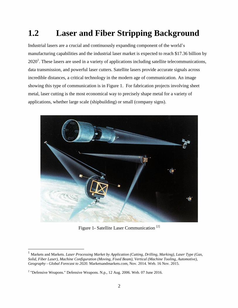
1.2 Laser and Fiber Stripping Background
Industrial lasers are a crucial and continuously expanding component of the world’s
manufacturing capabilities and the industrial laser market is expected to reach $17.36 billion by
20201. These lasers are used in a variety of applications including satellite telecommunications,
data transmission, and powerful laser cutters. Satellite lasers provide accurate signals across
incredible distances, a critical technology in the modern age of communication. An image
showing this type of communication is in Figure 1. For fabrication projects involving sheet
metal, laser cutting is the most economical way to precisely shape metal for a variety of
applications, whether large scale (shipbuilding) or small (company signs).
Figure 1- Satellite Laser Communication [2]
1 Markets and Markets. Laser Processing Market by Application (Cutting, Drilling, Marking), Laser Type (Gas,
Solid, Fiber Laser), Machine Configuration (Moving, Fixed Beam), Vertical (Machine Tooling, Automotive),
Geography - Global Forecast to 2020. Marketsandmarkets.com, Nov. 2014. Web. 16 Nov. 2015. 2 "Defensive Weapons." Defensive Weapons. N.p., 12 Aug. 2006. Web. 07 June 2016.

3
Typically when producing high powered lasers, a number of smaller fiber optic cables are joined
together from the laser generator3. However, each fiber has a polymer protective coating. To join
them together or metalize them for connection to electrical components, the protective cladding
must be stripped off of the silica interior4. Depending on how the cables are joined, the cladding
may need to be stripped off the ends of the fibers or removed from a “window” in the middle of
the fiber. There are two general methods for doing this, mechanical stripping and chemical
removal. Mechanical stripping cuts the fiber cladding and removes it physically. This can be
done by hand with tools similar to wire strippers or with automated machinery. Using a
mechanical method is effective but has a higher likelihood of nicking the fibers than chemical
stripping methods. Chemical stripping uses a variety of chemicals to remove the fiber cladding
and expose a window of silica beneath. The partially dissolved cladding fragments then need to
be removed with a cleaning process. The downside to this process is the safety hazard posed by
the chemicals used in this process.
1.3 Automated Manufacturing
Companies automate processes for a variety of reasons; they can reduce waste, increase quality
and precision, and improve safety. Many of the processes that companies automate are ones that
are dangerous or difficult for humans to perform. Tasks like these are usually the first to be
automated. Automated machines typically come in two major categories: generalized industrial
robots and specialized process solutions. General industrial robots are automated systems which
are flexible and programmable to many different tasks. They are usually arrayed into assembly
lines where they can be programmed to perform sequentially. For example, a robotic arm is a
general industrial robot that may be used for many tasks across many industries. In automobile
manufacturing robot arm lines perform tasks such as welding, drilling, and painting in sequence.
3 O'Connor, Michael, and Bill Shiner. Excerpt: High-power Fiber Lasers for Industry and Defense--Part III. Rep.
UBM Canon, 27 Apr. 2011. Web. 17 Nov. 2015. 4 Doyon, Pete. "Optical-fiber Window-stripping: Why and How?" Journal of Lightwave Technology 19.9 (2002).
Lightwave Online. IEEE. Web. 26 Oct. 2015.

4
Specialized process solutions are machines designed and built to perform a single task or stage in
a process. Examples of these are the forming tools used in steel beam production.
Figure 2- Automation Machine Used in the Manufactuing of Steel Beams[5]
The use of automated systems in industrial production requires a thorough understanding of how
the machine will fulfill its role. For industrial robotics to be a viable solution, technicians who
currently work on that process must approve of the new solution6. Lumentum’s technicians were
a part of the discussion and decision making process for approving the automated machine
developed by GLOWS CO; this procedure validates the construction for the A-CHEM and
follows the safety requirements outlined in the Geneva Convention article on Safety for
Industrial Robots. However, an automated process introduces new working hazards to the
workspace. Therefore, it is important for technicians to be trained properly in the use of the A-
5 Yangtong Group. "H Beam Assembly Machine,H Beam Automatic Assembling Machine." H Beam Assembly
Machine,H Beam Automatic Assembling Machine. Yangtong Group, n.d. Web. 07 June 2016.
6 "Accident and Injury Statistics." Safety in the Use of Industrial Robots. Geneva: International Labour Office,
1989. 15-20. Print.

5
CHEM before they are qualified to utilize this tool. Part of this design and construction process
is to identify potential dangers in the operation and fabrication of the A-CHEM.

6
2. Systems-Level
2.1 Current User Scenario
Lumentum currently employs a number of technicians to manually carry out the multi-stepped
window stripping process. The process is conducted inside of a fume hood located in a clean
room. The steps are laid out as follows:
1. The technician fills a number of heated baths with the first set of chemicals.
2. The technician waits roughly 5 minutes as the baths heat up.
3. The technician places the roughly 4.5 kg fiber carrying tool over each bath and dips the fibers
into the chemicals. The tool rests on the fume hood surface so the technician does not have to
hold it. After a prescribed amount of time the technician removes the tool.
4. The technician repeats the previous step for each of the filled baths.
5. The technician disposes of the used chemicals.
6. The technician fills a set of ultrasonically agitated baths with a new set of chemicals.
7. The technician places the FCT over each bath for a precise amount of time.
8. The technician disposes of the used chemicals.
The current process is dangerous because the technician is exposed to the hazardous chemicals
for the entire operation. The heated baths also pose a burning risk. The precision of the current
process is limited by the technician’s ability to hold the FCT steadily and without bumping the
fibers and by his or her ability to respond quickly and accurately to the process timer.

7
2.2 Customer Need
To increase safety and process quality, Lumentum contracted GLOWS CO to automate the
chemical window etching process described above. The automated chemical etching machine, or
A-CHEM, must complete the same process as the technician, but with more precision.
After the scope of the project had been informally discussed with Lumentum, interviews were
conducted with a Lumentum technician, Juan Lugo, a Lumentum design engineer, David Vecht,
and GLOWS CO’s senior advisor, Dr. Robert Marks, to gather more information about the
specifics of the project. All three interviewees consistently stressed the objectives of this project
in order of importance: safety, process repeatability, and usability.
In addition to the emphasized importance of safety, reliability, and usability, each had individual
elements of preference. David Vecht suggested that the machine should be very simple to
operate, ideally requiring only one button for normal operation. Having a one-push-go system
would provide simplicity to the design that could increase safety and help prevent misuse of the
tool. Juan Lugo had the same opinions about a system that only required one button to operate,
but the highlights of automating the process would be in improving the technician’s capability of
multitasking. Lugo found that while the process itself requires little thought, it requires a vast
amount of time to prepare and requires constant monitoring from start to finish. With one-button-
operation, more of a technician’s time would be free to work on other portions of the
manufacturing processes done in a clean room.
Robert Marks highlighted the importance of material selection. The materials used need to be
corrosion resistant to the chemicals used in the process and to the fumes generated by the
process. The materials for moving parts also need to be wear resistant to fulfill the clean room
requirement for the project. Lastly, the materials need to meet the lifespan requirements. This
means ensuring they are wear resistant to an extent that repeated use will not impact the accuracy
of the machine. The materials must also withstand fatigue such that they do not weaken during
the operational lifetime of the machine.

8
2.3 Market Availability
Mechanical or plasma fiber strippers are common methods of removing the cladding from fiber
optic cables and perform efficiently to remove the cladding on the ends of fibers. Additionally,
there are a wide variety of automatic and manual machines that perform these tasks; however,
they are not well suited for performing window stripping due to their configurations and
limitations. The available tools on the market require the cables to be threaded through the
stripping mechanism which would introduce process variations for Lumentum. Also, it would
interrupt Lumentum's assembly process which utilizes the FCT in other manufacturing
processes. Using these machines also limits stripping to only one fiber at a time and introduces
the possibility that the silica core is damaged as the cladding is stripped. Therefore, the available
machines on the market do not meet Lumentum's needs and other alternatives must be
considered.
Most industrial machines fall into two categories: standardized systems and unique problem
solvers. Standardized processes are those that occur in a large number of practices, but have
multiple methods of being solved. This makes machinery for these processes common due to its
common usage throughout different fields. A unique process, however, is one that is either very
new technologically or is only used in very specific applications. Currently there is no
standardized automated window chemical etching solution for fiber optic cables on the market
making Lumentum’s process unique. Automation company jobs are custom priced and are
frequently subject to bidding as the contracting company chooses a solution provider. However,
the bid-winning company gains access to sensitive manufacturing techniques which increases the
risk of leaked proprietary information. Also, machines custom built by professional bid
automation companies tend to be more expensive and must be serviced by the manufacturing
company. These conditions are undesirable to Lumentum, and the company has not utilized this
option, although it was considered.

9
Another solution is a general manufacturing solution: a robotic arm. Small robotic industrial
arms can have positional repeatability down to +/- 0.02 mm, more than enough for this
application. However, robotic arms have problems in terms of cost, design of a FCT interface,
and fitting inside the fume hood. If a robotic arm was used, it would be mounted inside the fume
hood and it would move the FCT to dunk it in each bath. A cradle for the FCT would have to be
manufactured to hold the FCT to the arm, as well as a base plate for the arm. NACHI
manufactures a small robotic arm (Figure 3) with a reach of 646 mm and a position repeatability
of +/- 0.03 mm for $29,000 which is one and a half times the acceptable budget for this project.
Denso also produces a robotic arm (Figure 4) that can move a maximum payload of 5 kg. It has a
reach radius of 550 mm with a repeatability of +/- 0.02 mm. It faces very similar problems to the
NACHI machine, but it can only move radially, so its movement will be limited within a fume
hood. Also, the tool from Lumentum weighs approximately 4.5 kg, which only leaves 0.5 kg for
the weight of the grabber with the Denso arm which is a small room for error.
Figure 3- NACHI MZ07L-01 Robot Arm Figure 4- Denso HS-4555G-P10 Robot Arm
The current process used by Lumentum’s technicians is a chemical stripping method that
requires manual movement of the FCT from bath to bath. Its advantages are that it utilizes the
chemical window stripping method, so center of fiber windows can be made with relative ease
without damaging or introducing particulates to the exposed fibers. This detail is crucial for the
manufacturing process because any defects in the fibers could lead to catastrophic failures for the
end product. Also, this manual process does not require any extra tooling or machines that would
require additional process training. One disadvantage of using a manual chemical stripping

10
process is that the technicians themselves are exposed to dangerous and caustic chemicals that
also produce volatile fumes. The close proximity to such liquids is required during the process
because the technicians must oversee all steps of this method. Also, the technicians do produce
errors in the stripping of the fibers due to their limitations in keeping accuracy and precisions
throughout the process. This can cause major problems in product reliability and expense due to
more units failing than if these errors did not occur. Although these methods are currently
employed, they are not suitable for maintaining a high level of safety for Lumentum's
technicians.
2.4 System Level Requirements
Synthesizing customer interviews, broad project guidelines, and field research together, a set of
system level requirements was assembled.
The automated etching machine must fulfill a variety of requirements:
o Reduce risk of injury compared to current process
o Fit inside fume hood
o Operate in a clean room
o Hold chemical baths and FCT
o Start when button is pushed
o Heat baths
o Move baths and FCT to and from each other
o Dip FCT into baths for a precise time and to a precise depth
o Move back to starting position and shut down once the process is complete
o Stop safely when emergency stop button is pushed
o Sound alarm if a process problem occurs
The synthesis processes also revealed a number of additional criteria to improve the A-CHEM,
but are not required:
o Require only 1 button to start
o Indicate time left in process by lights or display
o Move machine elements with buttons for manual control
o Facilitate cleaning by using easily removable parts

11
2.5 Core Design Principles
The needs and requirements detailed by Lumentum and its technicians are important and must be
taken into consideration when designing a solution. However, many of these requirements are
too broad or too specific to be directly applied when designing a full-spec system. To better
adapt the project and customer requirements, three major design principles were created as
operational guidelines: safety, process repeatability, and usability. These principles were applied
to help filter designs and subassembly selections throughout the project. By consulting how well
each solution addressed the core design principles, more subtle advantages in the design choices
were highlighted, helping to select an optimal choice.
2.6 Design Principle: Safety
The safety of the technicians for this automated process is the largest weighting factor in
determining suitable designs and subassemblies. The largest concerns that must be addressed by
GLOWS CO's solution are all safety related: chemical hazards, high temperatures due to heating
elements, pinching and entrapment from moving assemblies, and electrical hazards.
The dangerous chemicals used in window etching need to be properly contained and controlled
throughout the span of use for this automated process. This means that the chemicals should
never be in locations that could cause harm to a technician servicing or operating the machine.
Additionally, the liquids must be highly visible from any viewing angle of the machine, and the
chemical baths must be easily accessed, thereby promoting safety when they are loaded and
unloaded from the machine. The chemicals should not compromise the machine either, and the
design must properly address the possibility of chemicals escaping their respective baths.
Instances such as chemical sloshing during bath movement and liquid dripping when fibers are
dipped must be considered and addressed in the final machine. Finally, critical components that
have the possibility of chemical contact should be designed in a manner such that critical failure
does not occur if they are exposed to these corrosive materials.

12
This process requires the use of heating elements that are at temperatures hot enough to burn a
person. Heat must be properly contained so that risks posed to the users of the machine and the
machine itself are minimal. The design must include methods of insulating the heater blocks to
prevent leakage heating of the surrounding assemblies. Upon activation, the machine must
include a method of determining when the heating elements are active to warn operators of
potential danger. If the nearby assemblies reach high temperatures due to leakage heating by the
heater blocks, the technicians would be at risk of being burned.
Since the tool is automated, pinching and entrapment between moving assemblies is another
factor that must be taken into consideration. Industrial application motors are capable of exerting
high forces and torques when operating, so all systems that use them must have failsafe shutoff
mechanisms to reduce risk. The priority of the A-CHEM is to improve the safety of the operator
during the window etching process, and it must not violate Lumentum's safety requirements to be
suitable as an industrial machine.
2.7 Design Principle: Process Repeatability
Lumentum requires high process repeatability to eliminate wasted production runs and to ensure
its final products are of the highest quality. As such, GLOWS CO's A-CHEM must improve
upon the repeatability of Lumentum’s current manual process.
The alignment of the fibers as they are submerged into the chemicals is the first critical factor
dictating process accuracy. The fibers must be perpendicular to the solvent surface as they are
submerged. The dipping action must be smooth and controlled to minimize fiber and fluid
motion. This will help to maintain a high level of accuracy and provide optimal stripping quality.
The length of time that the fibers are exposed to the chemicals is the second crucial factor
determining the accuracy of the process. The chemistry involved in the chemical etching dictates
a precise dip time must be executed; within 1 second or 1% of the total dip time, whichever is
smaller. The fibers must enter and leave the chemicals within the time limit reliably to maintain
product quality.

13
The horizontal location of the fibers relative to the baths is the one of the critical factors of
process repeatability. The fibers must be centered above each bath properly to avoid collisions
between the fibers and the walls of the bath as the fibers are dipped into the chemicals. There
must also be enough clearance between the fibers and the bath walls to avoid the meniscus along
the walls of the bath, maintaining a consistent etch between baths.
The chemical baths must not spill during movement. Loss of fluid would change the height of
the chemicals in the bath and alter the length of fiber that is etched. Additionally, the surface of
the chemicals must be stable when the fibers are dipped to avoid etching variations in the fiber
cladding.
The following issues must be addressed to satisfy the aforementioned repeatability factors:
1. Vibrations may cause misalignment of the FCT or baths
2. Vibrations may disrupt the surface flatness of the chemical baths
3. Fatigue may degrade machine alignment over time
4. Rapid bath acceleration may cause chemical spilling
5. Debris may build up on moving components, disrupting smooth FCT or bath movement
6. Chemical spills may corrode any part of the machine, decreasing mechanical precision

14
2.8 Design Principle: Usability
The expected users of this machine are Lumentum's technicians, so the machine’s interface must
serve them and improve over the current method used. The machine's systems are required to be
user-friendly to increase technician safety and reduce confusion or mistakes made while using
the product.
The technicians are responsible for loading the chemicals and the FCT into the Automated
Chemical Etching Machine (A-CHEM). To facilitate this process and protect the technicians, the
A-CHEM must leave space for the technician to safely prepare the chemical baths to further
reduce chemical exposure time. The machine's design must minimize the need for technicians to
reach under or around machine parts to reduce safety risks such as pinching and entrapment
between moving assemblies.
To improve the functionality of the A-CHEM, a one-touch operation system will be used to
initiate the window etching process. To streamline the process for the technicians, a simple
control board with three main functions, start, reset, and emergency stop, will be used. Once the
system is loaded with the proper chemicals and the FCT is secured to the machine, the fume
hood door must be lowered to separate the technician from the fumes generated by the fiber
etching process. To begin the process, the start button is depressed; if the machine, at any time,
behaves differently than the prescribed process, the emergency stop button must be pressed. This
will trigger all systems to shut down allowing the technician to remove the chemicals and then
diagnose the errors in the system. Once this is completed, the reset button can be pushed to send
the bath sleds to their original locations. During operation, the machine has methods of self-
check to avoid possible failures. Limit switches and photogates, utilized along the length of the
machine and on each cart, keep the baths from going too far and forcing stops at various
checkpoints. These components increase the autonomy of the machine and ensure the technician
does not need their undivided attention on the process, unlike the manual method.
Another key factor in the GLOWS CO design is the maintenance of the machine. This will affect
the types of subsystems selected for lateral and vertical movement in the system. For both
subsystems, minimal and less intrusive maintenance will improve the quality and user experience
of the A-CHEM. The machine is expected to have an operational lifetime of 5 years, so high

15
quality parts and materials must be used to improve the system's corrosion resistance and fatigue
wear. By utilizing these types of parts, the A-CHEM will need to be serviced less often and the
frequency of replacing parts will be minimal.

16
2.9 GLOWS CO Solution User Scenario
The GLOWS CO Solution User Scenario is as follows:
1. The technician fills all of the baths and places them into slots in the A-CHEM.
2. The technician places the FCT into the A-CHEM.
3. The technician pushes the start button.
4. The technician keeps reduced attention to the process until the A-CHEM is finished.
5. The A-CHEM executes the window stripping process.
6. The A-CHEM resets to its starting position and turns itself off.
7. The technician removes the FCT.
8. The technician disposes of the chemicals.
This solution exposes the technician to the chemicals for roughly 10% as much time as the
current process. The technician is never exposed to heated baths which pose an increased safety
risk. Finally, the technician spends less time carrying out the window stripping process and is
free to work elsewhere for roughly 90% of the process. A drawing that was used while
formulating the user scenario is in Figure 5.
Figure 5- A-CHEM in Fume Hood during User Scenario

17
2.10 Design Priorities
GLOWS CO has informally prioritized a number of design guidelines to evaluate design choices
and shape new designs to meet the 3 design principles of safety, process repeatability and
usability.
Designs that do not require the technician to reach under or around any machine components are
prioritized. Reaching awkwardly around or through the machine increases the risk of the
technician spilling chemicals or entrapment between two moving assemblies.
To enhance process repeatability, designs with a minimum number of moving parts have been
prioritized. Moving assemblies have a higher likelihood of mechanical failure due to dynamic
loading scenarios. Additionally, their increased failure modes, such as alignment or binding
issues, can easily disrupt the operation of the machine and requires a higher level of maintenance
to continue operating smoothly. Reducing the number of moving systems reduces the overall
chance that the machine fails to accurately perform its mechanical functions. Specifically,
designs that require custom gear trains or custom mechanical assemblies like scissor lifts or cam
systems were considered but rated lower than those without such systems.
Designs that take up less space in the fume hood and maintain a low overall profile were
prioritized. Reducing the machine’s center of gravity significantly reduces risks of safety hazards
such as tipping as well as making the system easier for technicians to load and maintain.
A-CHEM designs with stable bath and FCT movement systems better met the design principles
than ones that were not. The systems must resist vibrations that could disrupt the surface of the
etching chemicals which must be flat and still. The movement systems must also resist
deflection. To do this, all movement systems must be supported with guide rails to minimize the
impacts of offset weights. The rails must be precise and rigidly attached to the frame of the
machine.
Additionally, designs that utilized a high proportion of prefabricated parts instead of custom
assemblies were preferred to reduce costs and simplify maintenance and replacement of
subsystems.

18
2.11 Primary Subsystems
The Automated Chemical Etching Machine (A-CHEM) will have three primary subsystems: bath
movement, FCT movement, and system controls.
The bath movement system will move the chemical baths into position with the FCT. It must
hold the baths securely and move slowly and steadily to not spill fluids. The heated baths weigh
approximately 1 kg so the system must be stiff enough to support their weight. The baths must be
moved accurately so they properly align with the FCT. The guides for the bath movement must
be precise to assist with preventing the fluids from spilling as well as to increase the accuracy of
movement. The bath movement system must actively sense the location of the baths, using rotary
encoders on the motors and linear encoders on the baths. Additionally, the motors that move the
baths need to be precise enough to ensure alignment with the fibers.
The FCT movement system will dip the fibers into the aligned bath. It must securely hold the
tool so that it does not shift during operation. This subsystem must not deflect under the load of
the tool, but it must be able to move the FCT up and down. The rails that guide the system up
and down must be precisely aligned and have sufficient surface smoothness so that the no
vibrations impact the movement or deflect it from its predicted path. The system must also track
the movement of the FCT to verify its location at all times. The motor that controls this system
must have a high enough precision to meet the requirements for dipping accuracy.
The power and controls system will supply power and control data to the bath and FCT
movement subsystems as well as to the bath heaters. This system must be capable of processing
the control algorithms in real time; i.e., without computer lag. The system must also sufficiently
supply power to the heaters, but that power will be strictly on/off. The system must be capable of
processing sensor input from the rotary and linear encoders in the FCT and bath movement
subsystems and continue to supply precise control data to the motors in those systems.
Additionally the power and controls system must be able to interface with the user through a user
control box.

19
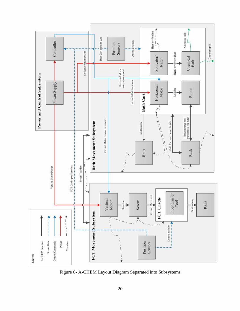
The subsystems and their constituent parts will interact with each other. Figure 6 shows how the
subsystems of the A-CHEM interact physically and digitally. The FCT movement subsystem
will be bolted to the bath movement subsystem, so vibrations, if they occur, would be transferred
between the systems. Likewise, the motors within each subsystem will transmit vibrations to the
frame they are attached to which will transfer vibrations to the other components attached to the
frame. Heat from the bath heaters will also transmit into the bath cart, and any chemicals spilled
from their baths will fall onto the carts and possibly into the bath movement frame.
20
Figure 6- A-CHEM Layout Diagram Separated into Subsystems

21
2.12 Project Challenges and Constraints
One of the biggest challenges to this project is the lag time in communication with Lumentum.
GLOWS CO met with Lumentum every 2 weeks and has little communication in the time
between those meetings. Getting confirmation and paperwork to clear official channels can thus
take long periods of time because our contact, David Vecht, must clear all of our paperwork with
Lumentum's legal team before we get it back. Two examples of this were, getting NDA
agreements, and the time required to get design requirements. GLOWS CO started initial work
on this project during the summer of 2015 and was able to observe the manual stripping process
in order to gain a better understanding of the process. This allowed GLOWS CO to begin work
on designing the A-CHEM, but an official set of design requirements was not received until 6
weeks after this initial observation. Those then had to be reviewed and discussed by GLOWS CO
before being returned to Lumentum for final confirmation. The NDA's took a similar amount of
time to fully complete. It took three weeks to receive the papers, and an additional two weeks to
sign and return.
The NDAs highlight another constraint for GLOWS CO, confidentiality. The process that
GLOWS CO is automating for Lumentum is a trade secret, and GLOWS CO needs to respect
that in the presentations and reports that are due. Trade secrets are an interesting legal entity in
that they can be protected and are the legal property of the owning company until they get out
and become public information. At that point they are no longer a trade secret. Trade secrets are
usually general enough that they are not patentable, or the patent process would reveal them in
such detail that other alternative methods would be easy to derive from the information. This
legal status usually applies to corporate recipes, manufacturing processes, and other process
oriented information.
Lumentum understands that GLOWS CO's disclosure of the A-CHEM in its entirety is essential
to the senior design project parameters, and has agreed to release dimensionless images and 3D
models of a select few of its components to support GLOWS CO's demonstration. Lumentum
does not wish to reveal the intricacies of its process though. This means that GLOWS CO must
conceal elements such as the exact chemicals used in the process, the number of baths used in the

22
process, and the timing on each dipping, among others. GLOWS CO therefore must be careful to
censor the released information to respect this secrecy, editing all published documents to reflect
the barrier between public information for GLOWS CO's project and private information relating
to the process itself.
Developing an accurate and realistic schedule to follow presented a difficult challenge to
GLOWS CO This is because of the relatively little experience GLOWS CO has with project
management or schedule estimations. GLOWS CO developed a schedule with expectations of
very rapid progressions in the design process, but found as the quarter progressed that many
sections had a tendency to take longer than anticipated. Elements of the initial design process
took far longer than expected and part selection was challenging as GLOWS CO learned about
integrated systems. GLOWS CO recognized this delay early though and accelerated the project
accordingly. Large buffer zones and over estimations of required time were incorporated into the
schedule despite the rapid expectations, meaning that GLOWS CO could fall about a week
behind schedule, and still meet the deadlines set by both the University and by Lumentum.
The complexity of this project posed a challenge in and of itself. This project required a lot of
system integration and dealt with a wide variety of mechanical constraints in construction. The
nature of autonomous systems also meant that the project incorporated the electrical and
computer engineering fields in addition to its mechanical engineering core. This meant that the
project required a high degree of dedication from the members of the GLOWS CO team to
bridge the knowledge gaps and create a working product. The team members, having varied
technical experiences in industry, were quite able to meet the challenge.

23
2.12.1 Budget
The budget of this project will be split into the different phases that lead up to and include the
final production model. The financial phases of the project are design, prototyping refinement,
and the final product. The split between these phases is roughly 5%, 45%, and 50% of the total
budget, respectively. The expectation for the design phase is to use minimal financial resources
as most modeling will be done in SolidWorks for visualization. Use of the SolidWorks software
package is available to all students through the Engineering Design Center at no additional cost.
The cost accumulated in this phase will most likely be due materials for a half-scale mock-up of
the product (likely foam core and wood) used to more easily determine accessibility of
subassemblies and their interfaces. The prototype phase will consist of purchasing and testing
simpler concept parts to assemble a workable design that meets most of the required functions.
The final product design will require all parts and assemblies are at full machine and clean room
specifications, meaning the end results will cost more than the testing portion. An expectation of
the projected cost breakdown for the final product can be found in the Appendix.
2.12.2 Timeline
While Lumentum was not directly involved in the setting of a project timeline, Lumentum was
given a deliverable date of July 2016 for a final product. To meet this deadline, initial design and
selection phases were completed in the Fall Quarter. By maximizing the time for design, fewer
resources were wasted during the prototyping stage testing systems that would not be used in the
final design. This prototyping phase took a considerable amount of time to ensure all subsystem
met the prescribed design criteria. Additionally, since a significant number of parts were
prefabricated, the timetable for construction was dependent on the arrival time of orders as
opposed to fabrication time. Due to the clean room specification of the machine, custom parts
underwent more rigorous development and cleaning; they also had to be manufactured by
certified machine shops, which increased part delivery time.

24
The final stage of the GLOWS CO project was the preparation for the Senior Design Conference,
beginning in the first week of April. During this phase, GLOWS CO developed their presentation
slides and demonstration as well as the final drafts of the project thesis. After these two deadlines
passed, the final month of the project focused on the construction of a final product for
Lumentum, which extended into the summer of 2016.
2.12.3 Design Process
The primary design process for this project was to meet as a group to discuss requirements, goals
and constraints, and then individually brainstorm and sketch these designs. The sketches and a
description of each design were then presented to the group. The group then made suggestions
and the design was refined and resubmitted to the group. To limit the number of designs, each
team member worked on only two to three designs at a time. Once the number of feasible
designs was reduced to around four, they were evaluated using decision matrices. Using a
weighting method, the designs were further narrowed down to two that incorporated synthesized
ideas from previous designs. The group then split to work on refining and improving these ideas
for use as the final design choice. At this stage in design, each concept was 3D modeled using
the Computer Aided Design program Solidworks to better visualize the end product. This
process required continuous review and GLOWS CO was confident that the design given at the
end of this CAD process was ready to begin prototyping.

25
2.13 Initial Designs
Initial brainstorming by GLOWS CO produced a plethora of subsystem designs, as exemplified
in Figure 7 that could be further developed. In order to produce a design that could be refined
into a working product, additional brainstorming and designing sessions were utilized. A
sampling of the initial designs and their main design characteristics are listed below. Also
included is a brief description of how these designs addressed the design principles and were
either synthesized into future designs or eliminated.
Figure 7- Images of Initial Design Sketches for Multiple Processes

26
2.13.1 Gantry Slide
Figure 8 shows one of the earliest designs, a gantry-slide designed to translate the FCT and raise
the stationary baths to the FCT. In this tool, the FCT would be secured to an overhead
framework operated using a lead screw system to maneuver the tool along the rails over
stationary chemical baths spaced beneath the framework. The baths are then raised using an
unspecified lifting mechanism to dip the hanging fibers into chemicals and then lowered so that
the system could drive the FCT to the next bath position. This process is repeated until all baths
have been used. The primary advantage of this system is the efficiency of space it had, making
the system more compact. However, the steps required to reset the position of the FCT made the
design cumbersome for operation, reducing the usability. Also, the overhead configuration of the
frame hindered the loading and unloading of the chemical baths before and after each process,
further limiting usability. For these two reasons, this design was removed from further
consideration
Figure 8- Gantry Slide Initial Drawing

27
2.13.2 Rotary Bath
Another initial design utilized a rotary base to cycle through the baths, as seen in Figure 9 above.
All of the baths are loaded and secured to a circular base. After loading the Fiber Carrying Tool,
the tool would dip into the baths and the base would rotate after each bath treatment. This design
would require only two motors, one for the base and one for the FCT movement system.
However, this system has some key design flaws that make it undesirable for use within the fume
hood. The loading and unloading of the chemical baths could be a potential safety hazard
because reaching over other filled baths or movement of the rotary subsystem is required.
Additionally, this might have created an electrical hazard because the twisting motion might
have damaged the rigid wires connecting the heating blocks to the power supply.
Figure 9- Rotary Bath Design Sketch

28
2.13.3 Cable Car
One of the other initial designs for the A-CHEM was a cable car design, as seen in Figure 8. This
design is similar to the rotary base design, with the baths loaded onto individual carts set on a
track. This design would be powered by some form of a pulley system (likely a power cable),
powering and pulling the interconnected baths around a circular track. When a car was properly
situated beneath the FCT, a vertical movement system would dip into the solvents and remove
the fibers once the step was complete. From a usability and safety standpoint, this design faces
the same issues when it comes to electrical hazards as the rotary system. In addition, the process
repeatability raised a problem with the interconnected cars carrying the baths, where the lack of
control over individual cars leads to a lack of accuracy for bath placement. These factors led to
the elimination of this design.
Figure 10- Cable Car Design Sketch

29
2.13.4 Fork-Car
After the initial brainstorm and the establishing the design principles of safety, process
repeatability, and usability, many of the designs were eliminated as viable options for the current
design. However, the design concepts were refined into more developed conceptual designs. One
of these designs is pictured in Figure 11, named Fork-Car.
Figure 11- Fork-Car Design Sketch
The Fork-Car design had stationary baths mounted to a baseplate, and the FCT was mounted to a
forklift lifting mechanism and moved along a rail also mounted to the baseplate. This design was
ultimately abandoned because of physical constraints that prevented the baths from being set up
in a way which would allow them to be dipped correctly.

30
2.13.5 Apollo
After eliminating more A-CHEM designs, two final designs were selected for a final design
review to select the current design. Both of these designs drew from previous design iterations,
creating two synthesized designs nicknamed Apollo and Artemis. At this stage of the design
process, a rough 3D model of each model was generated as seen in Figure 12 and 13.
Figure 12- Apollo Design CAD Model
Apollo was designed to translate the FCT above stationary baths using a custom FCT carrier.
Once the FCT was in place, the baths would be raised with linear actuators that were mounted
beneath them. This design addressed a number of design principles, namely that of safety and
system repeatability. The design itself is compact and rigid, designed to prevent chemical
sloshing from the bath movement. With vertical movement, the sloshing risks of the chemicals
are significantly lower than with lateral movement for the baths. Additionally the design
addressed the problem of the Gantry-Slide mentioned earlier in this section; the front linear slide
was moved to a lower position to make it easier to load the chemicals and chemical baths into
their respective spots in the A-CHEM. Despite this improvement, the usability of this design was
hindered by the FCT carrier. The FCT carrier made the act of loading the FCT more difficult.

31
2.13.6 Artemis
As mentioned in the previous section, the GLOWS CO team chose to work with the design
nicknamed Artemis. In the Artemis design, the baths are moved laterally while the FCT is moved
vertically. Each bath and its associated heater is mounted on a powered sled as seen in Figure 13.
Figure 13- Isometric View of Artemis
When the process was started, the sled would move the first bath to the center position on the
track beneath the FCT. Here, the FCT will wait a period of time before dipping to allow the
chemicals to settle within the baths; this was estimated to be in the range of 10-20 seconds. After
the liquid settled, the process would continue with the lowering of the FCT, dipping the fibers
into the chemical baths. After the prescribed time had passed to properly window etch, the FCT
would be raised to its resting level. The bath sled would then move to the opposite end of the
track to clear room for the next bath. This process was repeated for each bath. This sequence of
events is shown in Figure 14.
Z-Axis FCT Carrier
Stepper Motors
Frame
X-Axis Translation Sleds
Power Screws

32
Figure 14- Artemis Subsystems Process Operation from Start to Finish
This design had several advantages over the initial designs: it had an open design, heavy usage of
prefabricated parts, and efficient use of space in the fume hood. The orientation of the bath
movement system greatly improved the safety and usability of the machine because there are no
obstructions within the technician's operating space. With this configuration, the baths and FCT
could be easily unloaded and loaded. This would help avoid spills when filling the baths and
prevent overextension when loading the FCT onto its cradle. Although the horizontal motion of

33
baths can be undesirable because of sloshing, the speed and accelerations could be controlled in
such a way as to minimize this potential problem.
Most importantly, the technician would never have to place his or her hands between two
moving parts during normal operation. The technician would be loading the baths in the working
area of the A-CHEM, and all of the moving components are located either below or behind the
working area. This configuration reduced the chances of pinching or entrapment between
components, improving the overall safety of the tool.
Another advantage to this design is that it made heavy use of off the shelf parts, minimizing the
need for custom parts. Custom parts are very expensive compared to prefabricated parts because
they require a larger number of hours to produce, especially when stricter tolerances are required.
Mass production improves the cost effectiveness of the design through economy of scale. In this
design, Figure 13, the only parts that were custom made were the FCT cradle, the bath sleds, and
the stepper motor mounting brackets. The projected cost for this design was $6,883 (Appendix
F), which was below GLOWS CO's target range of $7,000 to $12,000 largely due to the number
of prefabricated parts. This cost was expected to rise as not all of the system’s components were
fully specified by the time the quote was generated.
Lastly, the slim profile of the tool also meant the baths are nearer the operating technician's
waist. This is an ergonomically comfortable level for humans to work at. The FCT loading
position is 20cm above that, still in an easily accessible and ergonomically comfortable level to
work at. This low profile and effective use of space in the fume hood also gave space to store the
chemicals inside of the fume hood. This would make filling the baths safer and easier by giving
easy access to the chemicals. The design also left space for protected containment of the
electronic components outside of the fume hood

34
3. Current Design The current design, called the A-CHEM, was built on the Artemis design seen in Section 2. The
A-CHEM made several improvements on the core Artemis design while keeping the same
general form. The changes to the design included the replacement of the stepper motor and screw
drive with a rack and pinion drive system, refinement of the vertical stage and the strengthening
of the frame. This design is shown in Figure 15 with the FCT and a single Heater Bath in place.
Figure 15 - Final A-CHEM Design
The operational process of the A-CHEM functioned very similarly to the operational process of
Artemis, seen in section 2.6. The process started with the technician loading the chemical baths
and FCT into the device. With Lumentum's hardware in place and the baths filled, the technician
would activate the heater blocks to heat the chemicals. These heater blocks were assumed to be
operated independently from the A-CHEM and could not be interfaced with by the A-CHEM
(mandated by Lumentum). The fume hood door was then lowered to the appropriate level and
Rack and Pinion
Bath Carts
Precision
Vertical Stage
Drive Train
Mounting
Block

35
the start button is depressed. The process would not start if the fume hood had not been lowered
properly, this would be confirmed by sensor verification. The operation would begin on a delay,
such that the heater blocks would have sufficient time to reach their full temperature. Once the
delay period had elapsed and the operating temperature reached, the first sled would move the
first bath to the center position on the track beneath the FCT. This center location would be
verified by an optical switch attached to the frame. The process is then paused 10-20 seconds to
allow the chemicals to settle. The exact time period varies due to the fill height of each bath and
can be tuned accordingly. The exact fill heights are considered trade secrets by Lumentum and
are concealed by GLOWS CO's NDA, sample calculations for an arbitrarily selected bath fill
height can be found in appendix B.2.
After the liquid was settled, the process would continue by lowering the FCT and dipping the
fibers into the chemical baths. After the prescribed time had passed to properly window etch, the
FCT would move back to its resting level. The bath sled would then move back to its starting
position to clear room for the next bath. This process is repeated for each bath, and can be seen
in Figure 16.
Figure 16- Subassembly Loading and Process Overview

36
The A-CHEM design has a number of advantages. Its construction is low profile, giving easy
access to the machine for both maintenance and loading. Similar to the Artemis design, since the
frame and the bath carts are close to the bed of the fume hood, it keeps the loading location
slightly above waist level. This also applies to the vertical stage which is lowered to frame level
when not in use. The A-CHEM is also a very modular design. The bath carts have all been
designed identically, including sensor mounting locations, allowing for the installation of as
many bath carts as can fit onto the design, at this point 6. The change from a stepper motor and
lead screw design to a rack and pinion design was key in enabling this modularity.
The desire for modularity was not the only reason for the change in drive system. The stepper
motor and lead screw drive from the Artemis design was abandoned in favor of a rack and pinion
design to save on cost, minimize disruptive vibrations, increase spill durability, and to allow for a
more modular design. While researching lead screws for the Artemis design, it was found that
lead screws with the required length of 4 feet or greater were very difficult to source in corrosion
resistant materials; the cost per unit of approximately $400. This led to a cost of over $1600 for
the lead screws alone, not including the cost of the drive motors. This cost was deemed excessive
and another solution was sought. Due to the size constraints of the fume hood and the difficulty
in finding long lead screws, reducing to a single lead screw that moved all bath carts was not
possible. To allow for sufficient space for the chemical baths on a single lead screw, the lead
screw would need to be long enough to accommodate the travel path of all carts on the system,
too long for the size constraints of the fume hood. To compress the space required for each bath
and to allow for independent movement of each bath, a rack and pinion drive system was
selected. This system allows for the baths not in use to stack in a compressed manner at the ends
of the track and not underneath the FCT. This prevents fumes from rising and either damaging
the FCT or corroding the protective cladding of the fiber optic cable in undesired locations. The
rack sourced for this prototype costs $79.37, significant savings compared to the cost of a lead
screw, and allows for carts to be added or removed at will as space allows. Additionally, the
geometry of the rack allows for additional support of the rack to help increase rigidity and reduce
vibrations, as will be seen in later sections.

37
There were 2 other major changes from the Artemis core design. The first is the replacement of
the lifting column with a precision actuator from Zaber. This modification gave the A-CHEM
increased dip accuracy in a compact form. The change is covered in more detail in the Vertical
Translation subsystem (Section 4.4). The other change is frame strengthening. Two additional
cross members have been added near the center of the frame. These serve dual purposes: to
increase frame rigidity and to provide additional mounting space for the vertical translation
subsystem.
The longevity of the A-CHEM depends highly on the materials used in its construction due to the
strenuous environmental conditions that it must operate under. While the prototype frame has be
constructed out of less durable 6061 extruded aluminum tubing, the machined parts have be
primarily made out of 6063 aluminum for its corrosion resistant qualities. Additionally the final
design has a frame specified for construction from 6063 U-channel tubing, and all aluminum
components will be anodized to increase their corrosion resistance. This will help to give the
complete machine an expected lifetime of 5 years.

38
4. Subsystems For ease of development, assembly, and documentation, the A-CHEM was split into four major
subsystems: the control system, the power grid, the vertical translation assembly, and the
horizontal movement assembly. The controls and power system exclusively deal with electronic
components as well as the logic required to code the A-CHEM. The vertical and horizontal
translations relate to the mechanical components which make up the final build and include a
few key electronic devices.
4.1 Controls
The Control Subsystem acts as the regulating body for the A-CHEM. In this subsystem the logic
controller is set up to receive feedback signals from the sensors that are set up in each of the
other subsystems. A condensed version of this system is shown in Figure 17; the complete
system can be seen in Appendix B. This subsystem is made up of the logic controller, sensors,
and the motor controllers. The logic controller used in the design is the National Instruments
cRIO-9063, a four module controller that allows for the complex logic that is needed to run the
A-CHEM. It was chosen for its versatility, its compatibility with a variety of sensors, and its
ability to run the motor controllers that were selected. The motor controllers of this system are
Victor SP slim motor controllers, manufactured by Victor Control Systems. These were chosen
due to their voltage characteristics, and Pulse Width Modulation (PWM) inputs. Additionally
the Control subsystem must allow for inputs that are generated by the user and relayed through
the User Interface.

39
4.2 Power System
The Power System consists of all of the electrical components in the A-CHEM and its control
system. The main goal of this system was to convert the lab’s 110 VAC power source into the
DC power needed to power the motors and devices used by the A-CHEM and its control
systems. A diagram of the wiring required for this project is shown in Figure 17, along with a
full page version in Appendix B.
Figure 17- A-CHEM Wiring Diagram

40
4.3 Sensor System
The sensors are used for positional location the bath carts on the A-CHEM and to communicate
that information to the controller. The sensors are wired to the digital sidecar, which routes their
input information to the C-RIO. This information verifies that the bath carts are at the center of
the track, and is used to determine if it is safe to perform the dipping operation. There are 3 types
of sensors that are used in the A-CHEM: limit switch, optical switch, and encoder.
Figure 18- Diagram of Sensor Locations.
Limit switches are switches that open/close when physically depressed. The limit switches used
in the A-CHEM were wired to be normally open. This means that the circuit running through
them is normally disconnected which prevents electricity from flowing through. When the switch
is depressed due to contact with another bath cart or the end block, the circuit is connected, and a
signal is passed through the wire to the controller. In practice, this is used as binary feedback to
tell the controller if something has gone wrong. If this is tripped during normal operation, then
the process is stopped immediately and the problem is communicated user through the control
panel. Additionally, this is used to calibrate the system, providing starting locations for the bath
carts.
Limit
Switches
Optical Switch

41
Figure 19- Picture of the Normally-Open Limit Switch [7]
The optical switch is combination of a light emitter and a light receiver that triggers a transistor.
When the emitted light is blocked, the transistor acts as a switch to open/close the connection.
This is mounted at the center of the frame, across from the vertical translation subsystem, and is
used to set the center position on the track for calibration and to verify the bath cart position
during normal operation. The optical switch used for the A-CHEM is normally closed. This
function is opposite to limit switch wiring described earlier, cutting the signal when the switch is
tripped. A small sheet metal tab hanging down from the underside of each bath cart acts as a
trigger for the optical switch. There is only one optical switch that is used in the A-CHEM
currently; however, an additional optical switch is planned to serve as the sensor to verify that
the fume hood door is lowered.
Figure 20- Picture of Optical Switch [8]
7 "Switch Micro Straight Lever Single Pole Single Throw5 Amp @ 250 Volt AC 5 Amp @ 30 Volt DC
0.127"" BSM2-0508-13: Jameco Valuepro: Electromechanical. N.p., n.d. Web. 07 June 2016. 8 "Digital Devices, Inc." Digital Devices, Inc. N.p., n.d. Web. 05 June 2016.

42
An encoder is the last type of sensor used in the A-CHEM. They are integrated into the Andy
Mark motors that drive the bath carts across the A-CHEM. These function by detecting
variations in the magnetic field within the sensor. As the encoder rotates, a notched ring passes in
front of a permanent magnet creating distinct fluctuations. It rotates with the motor shaft and
provides information as to both the rotational speed and the angular position. The changing
angular position can be used to determine the number of rotations, which can be converted into
distance and a position on the movement track that can be tracked. The positional information is
used to provide real time information to the controller regarding the position of the cart and to
give movement commands to the bath carts. The final position can then be cross-referenced with
the optical switch to verify that the cart is in the center of the track. The rotational speed of the
shaft can also be converted into linear velocity and controlled, ensuring same movement speeds
for the chemicals transported in the baths.
Figure 21- Picture of the Encoder [9]
9 "Digital Devices, Inc." Digital Devices, Inc. N.p., n.d. Web. 07 June 2016.

43
4.4 Vertical Translation
This subsystem is in direct conjunction with the design specification presented by Lumentum
(Appendix D) to hold and improve the tolerances used in the manual process. To do this
automatically, a high precision vertical stage must be used. Additionally, the tool used must be
stable enough to ensure dip accuracy and keep the FCT stable during operation. This vertical
stage, derived from Artemis, is intended to meet all specification criteria, but takes up a
significant portion of the cost for the A-CHEM. The stage selected is produced by Zaber, a
manufacturing company that produces single and multi-axis high precision stages which can be
programmed and controlled with LabVIEW. Due to its very high functional capabilities and
ease of programmability to the control system implemented in the A-CHEM, the Zaber X-
LRQ075BL-E01-KX13C model was chosen. With a resolution capability of 0.50 micrometers
and speed resolution of 0.30 micrometers/second, this tool fits all the specifications and
requirements needed to keep the dip accuracy required by Lumentum. Finally, it also meets the
loading criteria of the FCT when operating in the upright position needed to raise and lower the
fibers.
To attach the FCT to the Zaber stage, a cradle was designed and fabricated. This bracket used the
geometry of Lumentum's tool to grip, for locational accuracy, and to maintain a parallel with the
floor beneath. This is shown in Figure 22, the cradle with two long arms connected to a base
attached to the Zaber, as can be seen; this cradle allows for simple assembly and for very high
function. By using the central plate of the FCT as a registration point, the location of the fibers
can be controlled while at the same time maintaining a balanced holding point to keep the FCT
from tipping. To offset the high center of gravity the FCT and motor of the Zaber would
produce, a weighted machined block was designed to mount the Zaber in. Weighing over 10kg,
the block moved the center of gravity roughly 8cm down, increasing the stability of the
subsystem. This block was also used to designate a registration point to control the starting
location of the vertical stage. By controlling where the Zaber mounts to the A-CHEM, the
vertical accuracy will be more controllable and its motion will be smoother.

44
Figure 22- Solidworks Model of the FCT Cradle.
For Scale: Base Plate Length is 183mm
To increase the stability of the system and firmly fix the vertical stage to the frame, two support
brackets were designed. These brackets are in the form of "L" shapes, attached to the weighted
mounting block and to the frame's center, which can be seen in Figure 23. Using these brackets,
the frame would be able to counteract any moments produced by FCT movement and keeps the
assembly in one piece for ease of total system movement and adjustment. Additionally, the
connection to the frame helps distribute any vibrations generated by the Zaber tool during its
operation, greatly reducing the risk of dislocation of the FCT.

45
Figure 23- Solidworks Model of the Vertical Stage Subassembly.
For Scale: Overall Height of Assembly is 417mm
4.5 Horizontal Translation
To move the acid baths to the FCT, a frame must first be established. The frame consists of
extruded aluminum channels connected together, providing a robust base for the horizontal
movement system with the durability required to sustain the weight of the carts and a drive
system. Focusing on the design principles from Section 2, the usability of the design must be
very high, so the frame was adapted from Artemis. However, the key change from the
synthesized design to the A-CHEM was the introduction of crossbars near the center, as seen in
Figure 24, to mount the vertical stage rigidly.

46
Figure 24- Solidworks Model of Frame Subassembly
For Scale: Overall Length of Assembly is 1219mm
Fixed atop this structure is the support system for the horizontal translation required to move the
baths. The A-CHEM utilizes a rack-and-pinion drive system due to its higher availability and
lower overall cost in comparison to the stepper motor driven lead screw design used in Artemis.
To do this, a rack and two sliding rails were designed and selected to fix to the frame at two
points per beam. These connection points are at the ends, supported by pillow blocks as shown in
Figure 25.

47
Figure 25- Solidworks Model of Beams
For Scale: Overall Length of Assembly is 1219mm
After the support structure was designed, the carts to deliver the baths to the FCT were laid out.
The pinion on each cart is driven by an Andy Mark Neverrest 40 motor which has a high torque
output and built in encoders for controlling. Designed around the motor, the carts required a flat
base to fix the motor and sliding bearings to. The bearings used were high precision, Teflon
bearings procured from McMaster. These were attached at both ends of the cart for increased
stability.
To protect the electronic components below the base of the cart, a Teflon shield, as seen in
Figure 26, was used. This plate also serves as the interface point for the heater elements attached
to the acid baths, and so the Teflon shields are machined to create friction-fit mounting locations
for the heater blocks. The Teflon material was selected because of is high corrosion resistance
and low thermal conductivity. The low thermal conductivity thermally isolates the heater blocks,
preventing thermal runoff into the aluminum base plate of the bath cart.

48
Figure 26- Solidworks Model of Bath Sled Subassembly
For Scale: Overall Length of Assembly is 424mm
After initial evaluations of this system using Solidworks and Ansys modeling, the system was
deemed unsafe due to natural frequency vibrations operating around 60Hz occurring in the
support structure. That is, the beams would be excited by the frequencies of the electrical grid
this machine will be operating in, causing a large safety and operational hazard. For full
vibration cases see Appendix B.2. To solve this design problem, the effective length of each
beam can be shortened. Two support pillars were added to each beam, fixing them to the cross
channels that the frame provides. By fixing the beams at two additional points, their natural
frequencies were driven to a range of 200Hz-300Hz, greatly improving the operational safety of
the system. As a consequence of this design change, the support beams were also strengthened in
bending.

49
5. Design-Build and Testing
5.1 Initial Build
Once the CAD models were complete and the initial revisions made, the CAD models were
made into engineering drawings for the machining process. Machining was completed by a
professional machining company that specializes in metric machining. The parts were received
and initial prototype building began in lab space provided to us through the School of
Engineering and by our advisor Professor Marks.
This process was well documented with pictures taken during each stage of assembly to assist in
the creation of Work Instructions that are part of the final delivery to Lumentum. A sample of the
pictures taken is shown in Figure 27 which shows the unassembled pieces that make up the FCT
Cradle which were manufactured according to the detailed drawings found in Appendix C.
Figure 27- Picture of the FCT Cradle Parts Unassembled
Another part of the build was the construction of an enclosure to contain the A-CHEM during
testing. This enclosure was constructed of wood and Plexiglas to the dimensions of the fume
hood that was specified in the PDS. This enclosure also acted as the electronics box because all
of the electronics were attached to the inside left-hand plane of the enclosure. Additionally, the
interface box with the control buttons and status light were attached to the front of the enclosure.
A picture of this initial prototype assembly with its enclosure is shown in Figure 28.

50
Figure 28- Picture of the Completed Initial Prototype of the A-CHEM
5.2 Revisions
The biggest problem with the initial design was the alignment of the bearings on the bath sleds.
The rails, bearings and machine frame all required precise alignment in order for the bath carts to
move effectively. Even with the team's best efforts at aligning the machine, the bearings tended
to get stuck on the rails as they moved.
Ideally, the pinion that drives the bath cart would be aligned in the center of the two linear
bearings, but this was not possible due to size constraints. This caused the motor to push
unequally on the two bearings, causing the bearings to bind on the rails.
To resolve this issue, the front bearing was replaced with a flat block of HDPE that sat on the
rails, as shown in Figure 29. Because the new flat bearing had no contact with the sides of the
front rail, it could not bind on the rail if it came out of alignment. However, this meant that the
back bearing would be all that kept the cart straight because the front bearing could not resist
torque on the sled. The decrease in precision that resulted from the change in bearings was
deemed acceptable, as the lateral position of the bath carts has a large tolerance of about 1cm.

51
Figure 29-Bath Cart Bearing Modification
5.3 Testing
Once the bearings were modified and the carts could be moved smoothly and freely by hand, the
vertical and horizontal translation systems were operated together to execute a fiber dipping
motion. One bath cart with a 3-D printed model of a heater block was installed on the rails, and a
3-D printed model of the FCT was placed into the FCT cradle. The bath cart was manually
controlled by adjusting the current supplied to its motor from a variable DC power supply. The
motion of the FCT was controlled by a computer communicating with the Zaber linear stage.
In this preliminary test, the bath cart was started from rest at one side of the A-CHEM. By
increasing the current supplied to its motor, the bath cart moved to the center of the machine,
where it was stopped smoothly by decreasing current to zero. Once the bath cart had moved the
bath into position under the FCT, a LabVIEW script was activated manually. The script ran the
Zaber linear stage, moving the model FCT down, then back up after a pause.
After the FCT moved to its home location, the positive and negative motor leads of the bath cart
were switched, allowing the bath cart to move in the opposite direction. Once the FCT motion
stopped, the bath cart was driven back to its starting location.

52
To ensure that the baths would not spill their chemicals, a test of the bath cart movement system
was executed with water as an analog for acid. One bath cart was wired to an adjustable DC
power supply, and its bath was filled with an amount of water approximately equal to the amount
of acid that would fill the bath. The current supplied to the bath cart motor was modulated up and
down to simulate both normal and aggressive bath movement, and no water spilled from the
baths. Additionally, a timed test was done to determine the amount of time needed to wait for the
liquid to settle after movement. This settling time, after testing about 10 cases with varying
speeds was always less than 20 seconds. When low speeds were used (< 30 cm/s) the settling
time was approximately 6 seconds, which does not affect the etching process with a factor of
safety of 3.
5.4 Final Prototype Build
The revisions listed above were implemented, and incorporated into the A-CHEM. The drawings
of the A-CHEM were revised in order to reflect these changes. The Final Prototype is shown in
Figure 30 below.
Figure 30- Final Prototype Build of the A-CHEM

53
6. Project Management
6.1 Group Safety
The GLOWS CO team will not use or come into close contact with caustic chemicals; all liquids
were simulated with water. The machine is motorized and involves a number of moving
assemblies. This section will describe and analyze potential safety hazards and the mitigations
involved in the manufacturing, assembling, testing, operating, displaying, storing, and disposal
of the parts used in this project.
6.1.1 Manufacturing
Many parts used in this project were fabricated by a local machine shop and purchased off the
shelf. A handful of parts were manufactured in the Santa Clara University machine shop. To
mitigate the risks involved in machining, all parts underwent the required vetting procedures
before being produced. During the machining process the GLOWS CO team followed all
Mechanical Engineering Lab safety guidelines, and after machining the GLOWS CO team
ensured that every machined surface is free from burrs or sharp corners.
6.1.2 Assembly
Risks in the assembling of the machine could result in pinching of skin, cutting due to sharp
corners and edges, or crushing from dropped parts. Pinching can occur when adjacent parts close
in on a person causing small cuts or bruises. To prevent injury during the assembling, clear
communication between people assembling the machine was enforced. To protect against injury
from dropped parts, care was taken to grip the parts securely and heavy parts were moved by
groups. All sharp edges were removed before assembling them into the machine. Safety glasses
were worn at all times by all team members when in the workshop.

54
6.2 Tests and Operation
Risks in these stages fall under two major categories: physical and electrical.
6.2.1 Physical Risks
Moving parts in the A-CHEM pose an increased risk of pinching, entrapment, entanglement, and
volatile particulates. Entrapment occurs when any part of a person is stuck between parts of the
machine. Entanglement occurs when an article of clothing gets caught in a rotating or moving
part and draws the person wearing the clothing into the moving part. With electric motors
powering the various subsystems, there is a risk of unexpected movement that could put users at
risk of injury. To mitigate the risk of pinching, entrapment and entanglement, the machine was
only powered on after everyone had moved away from the machine. To further protect against
entanglement, no one wore anything on their lower arms or dangling from their body that could
be caught in moving machine such as jewelry or baggy clothing. The moving parts of the
machine could potentially throw small pieces of debris into the air. To reduce this risk, the
machine’s moving parts were thoroughly cleaned before it was powered on and safety glasses
were worn at all times in proximity to the machine. Also, the design of the machine incorporates
covers and shielding on moving assemblies and motors.
6.2.2 Electrical Risks
The power and control subsystems of the machine pose a high voltage shock hazard. In general,
GLOWS CO followed the Santa Clara University electrical safety guidelines. Unnecessary
electrical components were removed from the electrical system for each test. The system had no
batteries, but the various components may include capacitors and inductors that store electrical
potential
No live work was conducted on the machine. The wiring insulation of the machine was visually
checked before any operations and all other charged parts were protected from accidental contact
during normal operation. The baths were only filled with water when it is necessary to test the
bath heater or the kinematic response of the water in the moving baths. When water was used,
care was taken to ensure no electrical components get wet.

55
6.3 Display
When being displayed, the machine was either disconnected completely from electrical power or
was enclosed within a safety box. When not moving, the machine is incapable of causing
pinches, entrapment or entanglement. It was placed on a stable table or counter so it did not fall.
The machine was not filled with water or chemicals during any display scenario.
6.4 Storage
The machine was stored in a dry, room temperature environment. It was placed where it did not
present a tripping hazard or impede normal movement. The machine was covered to protect it
from dirt and to protect people from any sharp edges.
6.5 Disposal
GLOWS CO did not generate any hazardous waste while manufacturing the A-CHEM. All waste
that GLOWS CO generated was recycled or disposed of appropriately, like aluminum beams and
plastic packaging. All waste generated by the manufacturer of the machine's components has
been handled by the manufacturer.

56
7. Engineering Standards
and Realistic Constraints
7.1 Economics
Economic constraints played a significant role in the development of the A-CHEM due to
GLOWS CO’s budget and goals. GLOWS CO fulfilled the aforementioned goals and
requirements while balancing costs. However, to date, the budget has only eliminated several
expensive prebuilt components from consideration. GLOWS CO created an experimental
business plan to analyze how successful an automation company working with machines similar
to the A-CHEM could be. This plan can be found in Appendix J.
The A-CHEM will have a large impact for Lumentum by decreasing process variation in
manufacturing and minimizing the time spent by technicians on this portion of the fiber laser
process. The tool’s design will also minimize operating costs such as maintenance, part
replacement, and electrical power to increase the machine’s operational value. Additionally, the
machine will have a five-year lifetime which impacts the quality of parts utilized and the cost.
7.2 Manufacturability
Designing for manufacturability imposes many constraints on the A-CHEM. The following are
examples of methods to increase the manufacturability of the machine:
Minimize the total number of parts.
Minimize the variety of highly standard parts like bolts.
Fabricate large parts from multiple smaller parts.
Design custom parts to require minimal material removal.
Design custom parts to be made from the same materials.
Use standard parts wherever possible.

57
7.3 Ethics
GLOWS CO faces a number of ethical responsibilities: to itself, to Lumentum, and to the
technicians who operate the machine and society.
The members of the GLOWS CO team must treat each other ethically as they work on the
project. Work must be shared equally, deadlines and requirements must be met, and everyone
must be treated with respect.
GLOWS CO has a number of ethical obligations to Lumentum. First, GLOWS CO must deliver
a safe and accurate machine to etch fiber optic cables by July of 2016. The safety concerns are
addressed above. To meet the deadline, GLOWS CO has created an aggressive schedule to
ensure that they have enough time to manufacture, test and refine the machine.
In order to interface with Lumentum’s existing technology, Lumentum has provided GLOWS
CO with proprietary information that GLOWS CO is contractually obligated to keep
confidential. GLOWS CO has developed a peer-check process to minimize the risk of divulging
proprietary information, but should any breach occur, GLOWS CO must notify Lumentum.
GLOWS CO is also responsible for providing Lumentum with all technical documents,
instructions, potential problems and uncertainties relating to the design. The information must be
as complete as possible so the machine can be utilized to its full potential.
To facilitate the change in ownership and operation of the machine, GLOWS CO will provide
Lumentum with the personal contact information of the design engineers so that future operation
problems can be addressed directly by the most knowledgeable people.
Most importantly, GLOWS CO must hold the personal safety of anyone who uses the machine to
the highest regard because the machine has the capacity to injure persons who operate or interact
with it.

58
7.4 Environmental
GLOWS CO has the ethical responsibility to select materials and manufacturing processes for
the A-CHEM that does not harm the environment significantly more than the alternatives.
Because the machine will decrease the number of failed fiber etching processes and is using the
same amount of chemicals currently used, the net long-term environmental impact will be
positive.
8. Summary and Conclusion
The design of the current A-CHEM met the key points of safety and accuracy for Lumentum.
The use of commercially available parts in the construction of the machine led to a lower overall
cost, with the custom parts being responsible for the necessary accuracy of this process. By
keeping major aspects of the design simple, the fiber etching process can be streamlined.

59
Appendix A: Bibliography 1
Markets and Markets. Laser Processing Market by Application (Cutting, Drilling, Marking), Laser Type
(Gas, Solid, Fiber Laser), Machine Configuration (Moving, Fixed Beam), Vertical (Machine Tooling,
Automotive), Geography - Global Forecast to 2020. Marketsandmarkets.com, Nov. 2014. Web. 16 Nov. 2015. 2 O'Connor, Michael, and Bill Shiner. Excerpt: High-power Fiber Lasers for Industry and Defense--Part III.
Rep. UBM Canon, 27 Apr. 2011. Web. 17 Nov. 2015. 3 Doyon, Pete. "Optical-fiber Window-stripping: Why and How?" Journal of Lightwave Technology 19.9
(2002). Lightwave Online. IEEE. Web. 26 Oct. 2015.
4 "Accident and Injury Statistics." Safety in the Use of Industrial Robots. Geneva: International Labour Office,
1989. 15-20. Print.

60
Appendix B: Detailed Calculations
Appendix B. 1 Vibration and Bending Analysis
Figure 31- Visual Representation of the A-CHEM for Analysis
Simplifying Elements and Assumptions
For all subassemblies, screws, nuts, and washers were removed to reduce meshing constraints
and reduce extraneous calculations the software must accomplish. Also, this helped remove
solid model overlaps that otherwise would have caused errors while meshing and calculating
results. Screw threads typically enter material in holes made within Solidworks due to how it
creates and models threads and their associated threaded holes.
Additionally, some larger parts were removed from models because they were not loaded: the
rack shield did not attribute a significant rigidity to the sled support system, so it was not

61
factored into the model. Also, the sled itself was not used in the model for static loading as it
was simulated with either a point load or distributed load depending on the situation being tested.
Finally, all materials were assumed to be either Aluminum Alloy 6063-T6 or 6061-T6 based on
the selection criteria of materials due to caustic chemicals and their availability in pre-fabricated
parts.
For hand calculations, beams were assumed to have a pinned-pinned connection which
overestimates the bending of parts and allows us to include even more factors of safety. Most
beams can be considered to have a fixed-fixed connection within our assemblies due to the
methods chosen to clamp them together.
Vibrational Analysis
Figure 32- Simplified Sled Assembly Used for Testing
This analysis was used to determine the natural frequencies of the support beams used in this
assembly under various configurations. These configurations are listed below:

62
1. Support System without sleds
2. Support System with a single sled positioned on a side
3. Support System with a single sled positioned at the center
4. Support System with two sleds positioned on a side
5. Support System with two sleds positioned one on a side one in the center
6. Support System with two sleds positioned one on each side
7. Support System with three slides positioned two on a side one on the opposite side
8. Support System with three slides positioned two on a side on in the center
The model was assumed to be rigidly fixed at the bottom of the end pillow blocks because they
would be attached to the frame. For purposes of this analysis, all the parts were assumed to be
Aluminum Alloy 6063-T6.
Table A- List of Vibrational Analysis Results
The results for these configurations show that the system must not be loaded around 45 Hz,
60Hz, 75Hz, 90Hz, and over 100Hz. All of these are not very likely to happen in our system due
to the very low movement required for stability of the chemicals within the baths, but it is good
to be mindful of these results. Additionally, from the models, if these natural frequencies were
used during movement, we could excite some of the structural members to oscillate at

63
amplitudes over nearly 5 inches, which would not only damage the assemblies but also spill
chemicals on everything.
Bending Analysis
The three subassemblies detailed before were loaded with realistic values derived from existing
part weights and package loads. Table B shows the different loads applied to the subassemblies
and their results for displacement, Von Mises stresses and relevant reaction forces.
Table B- Bending Analysis Results
This model looked at various cases of loading based on how many carts were being simulated.
Initially, one cart’s weight was applied on the three supporting beam’s center which is roughly
70 Newtons. Figures 33 and 34 show the load’s orientation, locations, and resulting maximum
displacements of the beam. With the same model, a worst case simulation was considered where
one of our members could accidentally fall onto the beams, thus loading them with roughly
1000N which can be seen in Figures 35 and 36.

64
Figure 33- Bath Movement Subassembly Bending Analysis Side View (70N)
Red Zones 7.78E-1 mm, Green Zones 3.89E-1 mm, Blue Zones 0 mm defelection
Figure 34- Bath Movement Subassembly Bending Analysis Top View (70N)
Red Zones 7.78E-1 mm, Green Zones 3.89E-1 mm, Blue Zones 0 mm defelection

65
Figure 35- Bath Movement Subassembly Bending Analysis Side View (1000N)
Red Zones 1.12E+1 mm, Green Zones 5.55E0 mm, Blue Zones 0 mm defelection
Figure 36- Bath Movement Subassembly Bendng Analysis Top View (1000N)
Red Zones 1.12E+1 mm, Green Zones 5.55E0 mm, Blue Zones 0 mm defelection
After the loading simulations for the bath subassembly was completed, the FCT support
assembly was examined. Lumentum has specified the FCT will be approximately 10Lbs, so we

66
used this value in our analysis. Figures 37 and 38 show the orientations and location of the
forces used in this model. The load is split between the two side brackets because that is how it
would be loaded physically. To take this to a worst case scenario, we assumed a maximum load
of 1000N to simulate a person putting their full weight on the support bracket with the FCT in
place. The results of this test can be seen in Figures 39 and 40.
Figure 37- FCT Support Subassembly Bending Analysis Side View (10 lbs., 44.48 N)
Red Zones 1.34E-2 mm, Green Zones 6.68E-3 mm, Blue Zones 0 mm defelection
Figure 38- FCT Support Subassembly Bending Analysis Top View (10 lbs., 44.48 N)
Red Zones 1.34E-2 mm, Green Zones 6.68E-3 mm, Blue Zones 0 mm defelection

67
Figure 39- FCT Support Subassembly Bending Analysis Side View (1000 N)
Red Zones 3.00E-1 mm, Green Zones 1.50E-1 mm, Blue Zones 0 mm defelection
Figure 40- FCT Support Subassembly Bending Analysis Top View (1000 N)
Red Zones 3.00E-1 mm, Green Zones 1.50E-1 mm, Blue Zones 0 mm defelection
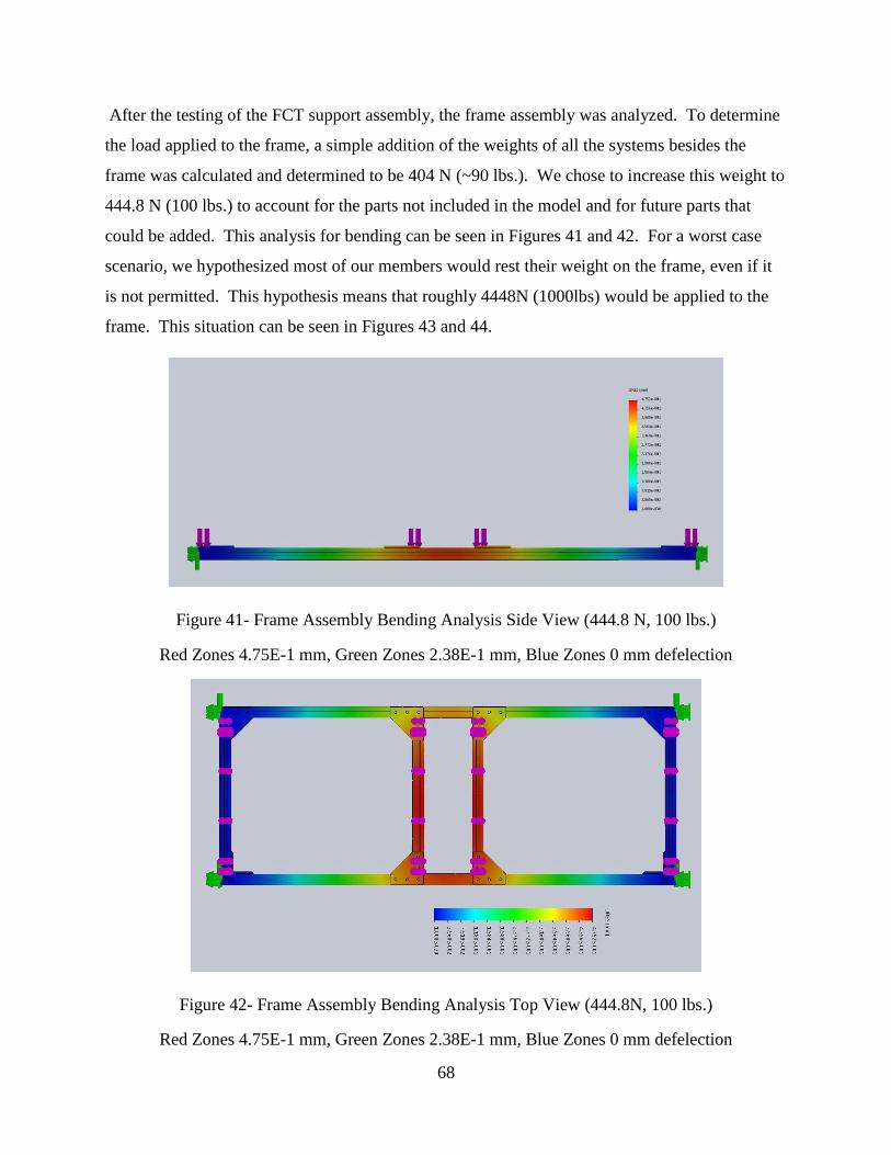
68
After the testing of the FCT support assembly, the frame assembly was analyzed. To determine
the load applied to the frame, a simple addition of the weights of all the systems besides the
frame was calculated and determined to be 404 N (~90 lbs.). We chose to increase this weight to
444.8 N (100 lbs.) to account for the parts not included in the model and for future parts that
could be added. This analysis for bending can be seen in Figures 41 and 42. For a worst case
scenario, we hypothesized most of our members would rest their weight on the frame, even if it
is not permitted. This hypothesis means that roughly 4448N (1000lbs) would be applied to the
frame. This situation can be seen in Figures 43 and 44.
Figure 41- Frame Assembly Bending Analysis Side View (444.8 N, 100 lbs.)
Red Zones 4.75E-1 mm, Green Zones 2.38E-1 mm, Blue Zones 0 mm defelection
Figure 42- Frame Assembly Bending Analysis Top View (444.8N, 100 lbs.)
Red Zones 4.75E-1 mm, Green Zones 2.38E-1 mm, Blue Zones 0 mm defelection

69
Figure 43- Frame Assembly Bending Analysis Side View (4448N, 1000 lbs.)
Red Zones 4.75E0 mm, Green Zones 2.38E0 mm, Blue Zones 0 mm defelection
Figure 44- Frame Assembly Bending Analysis Top View (4448N, 1000 lbs.)
Red Zones 4.75E0 mm, Green Zones 2.38E0 mm, Blue Zones 0 mm defelection

70
Hand calculations were also done for this analysis; they most corresponded with the analysis
done in Figures 33 and 34, where they model the single sled on the beams. The values were very
close so we knew that the program had not grossly overestimated our loads. Additionally, we
had found that there were no displacements, due to loading, greater than 3mm in the bath
movement subassembly. This is good because the maximum valuable allowed for this assembly
to displace is 5mm to maintain proper gear/rack meshing. These hand calculated values are
shown on the following 3 pages, in Figure 45, 46, and 47.

71
Figure 45- Bending Analysis Hand Calcuations Page 1

72
Figure 46- Bending Analysis Hand Calculations Page 2

73
Figure 47- Bending Analysis Hand Calculations Page 3

74
Appendix B. 2 Bath Sloshing Analysis

75
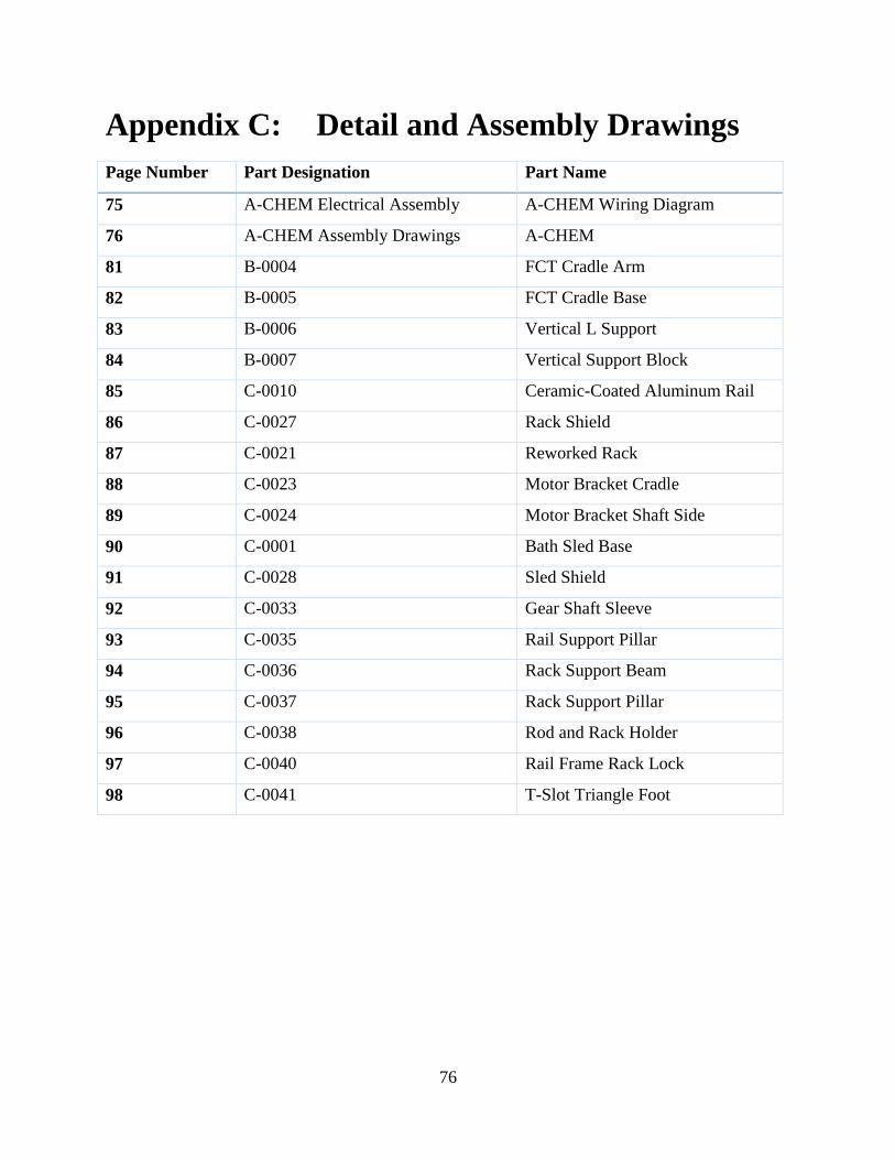
76
Appendix C: Detail and Assembly Drawings
Page Number Part Designation Part Name
75 A-CHEM Electrical Assembly A-CHEM Wiring Diagram
76 A-CHEM Assembly Drawings A-CHEM
81 B-0004 FCT Cradle Arm
82 B-0005 FCT Cradle Base
83 B-0006 Vertical L Support
84 B-0007 Vertical Support Block
85 C-0010 Ceramic-Coated Aluminum Rail
86 C-0027 Rack Shield
87 C-0021 Reworked Rack
88 C-0023 Motor Bracket Cradle
89 C-0024 Motor Bracket Shaft Side
90 C-0001 Bath Sled Base
91 C-0028 Sled Shield
92 C-0033 Gear Shaft Sleeve
93 C-0035 Rail Support Pillar
94 C-0036 Rack Support Beam
95 C-0037 Rack Support Pillar
96 C-0038 Rod and Rack Holder
97 C-0040 Rail Frame Rack Lock
98 C-0041 T-Slot Triangle Foot

77

78

79

80

81

82

83

84

85

86

87

88

89

90

91

92
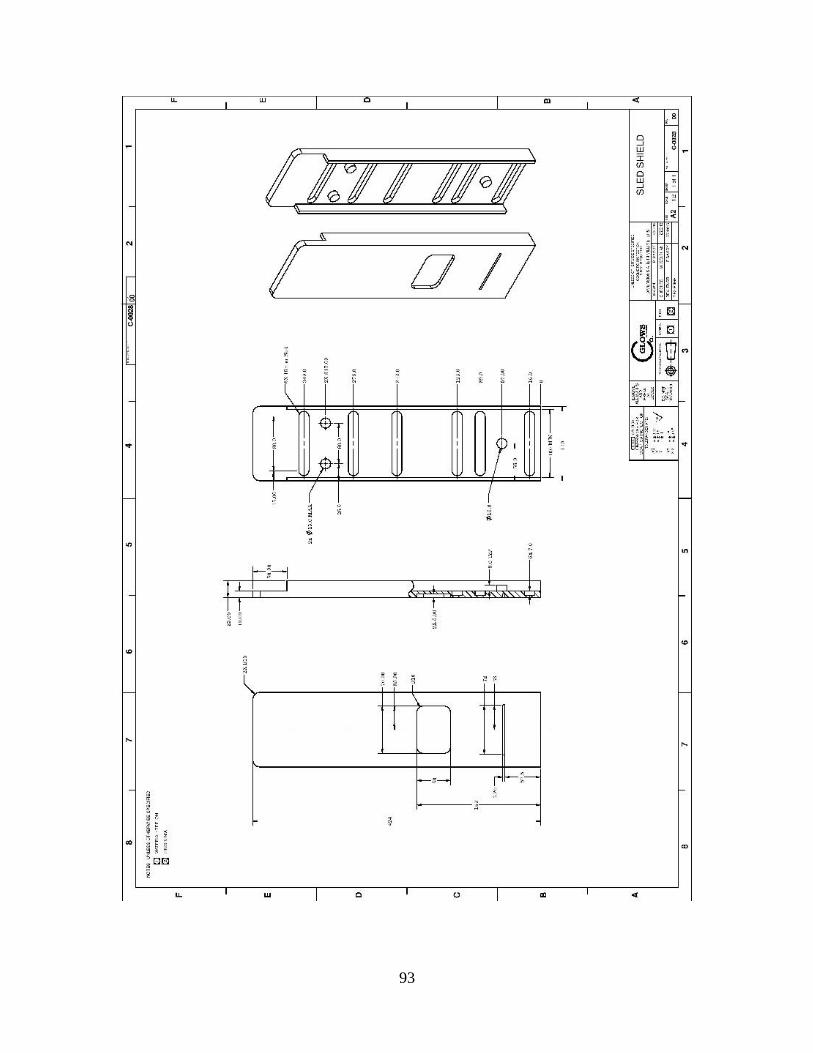
93

94

95

96

97

98

99

100

101
Appendix D: PDS
Datum description: Lumentum’s current manual process which is manually performed using
Lumentum’s equipment.
Elements/Requirements Units Datum Target Range
Process
Bath Side-Side Accuracy mm 5 2.0
Bath Maximum Velocity mm/s N/A 50.0
FCT Vertical Accuracy mm 2 1.0
Fiber Dip Time Accuracy s 15 1.0
Maximum Vertical Acceleration m/s2 N/A 0.05
Fiber Table Max Acceleration m/s2 N/A 0.1
Fiber Table Max Velocity mm/s N/A 30.0
Heats Acid Baths Yes/No Yes Yes
Heater Block Control On/Off Yes/No Yes Yes
Does Not Excite Natural Frequencies Yes/No N/A Yes
Time Between Baths s 45 20-30
Has Reset Function? Yes/No N/A Yes
Only Operates When Fume Hood Closed Yes/No No Yes
Class XXXX Clean Room Yes/No Yes Yes
Physical Requirements
Max Depth m N/A 0.6
Max Width m N/A 1.8
Max Height m N/A 1.0
Interfaces With Lumentum Tool FCT Yes/No Yes Yes
Dynamic Loading Yielding FOS N/A >5
Operating Temperature C 10-30 10-30
Safety
Human Interface Start/Stop Only Yes/No No Yes
E-Stop Reliability % N/A 100
Movement Components Shielded? Yes/No N/A Yes
Must Be Easy To Load and Unload Baths Yes/No N/A Yes
No Heat Leaking Yes/No N/A Yes
Power Supply N/A N/A Single Phase
110V
No Sharp Corners Yes/No Yes Yes

102
Maintenance
Surface Wear Yes/No N/A No
Sulfuric Acid Resistance Yes/No N/A Yes
Lifespan Years N/A 5
Cycles Before Human Calibration Cycles N/A 500
Parts Removable? Yes/No N/A Yes
Other
Delivery Date Date N/A 7/29/2016
Total Cost of Final Tool $ N/A 12000
Other Project Requirements
-machine must interact with existing fiber-holding tool
-etched section of fibers must never touch each other
-machine must be easily serviceable
-machine must thermally insulate bath heaters from rest of machine
-baths should be easy to remove from the machine
-machine controls should be simple to use

103
Appendix E: Manufactured Parts Quote

104
Appendix F: Projected Cost
Table C- Expected Final Product Cost
Item: Cost:
Purchased Parts - Accessories $3,904
Screws-Hardware $180
Frame Support Material $104
Lifting Mechanism $3,420
Linear Slide Rails $200
Processing Board/Controller $1,799
NI CompactRIO-9063 $1,299
Controlling Modules $500
Machined Parts $1,200
FCT Cradle $800
Bath Assembly Support Beams $400
Motors and Controllers $1,980
Stepper Motor + Controller Combo $1,000
Motor Driver Board $980
Total: $8,883

105
System Description Original
Manufacturer
Manufacturer
Part Number
Part
Number
Cost/
Part Qty. Total
General M3 Thread, 16mm Length,
.5mm Pitch McMaster Carr 92290A120 A-0001 $0.20 100 $20.00
General M6 Thread, 25mm Length,
1mm Pitch McMaster Carr 92290A330 A-0003 $0.47 100 $47.00
General Type 316 Stainless Steel Flat
Washer, M6 Screw Size McMaster Carr 90965A170 A-0004 $0.07 100 $7.00
General Type 316 Stainless Steel Split
Lock Washer, M6 Screw Size McMaster Carr 92153A426 A-0005 $0.06 100 $6.00
General M6 Thread, 18mm Length,
1mm Pitch McMaster Carr 92290A323 A-0006 $0.42 100 $42.00
General M3 Thread, 25mm Length,
.5mm Pitch McMaster Carr 92290A124 A-0007 $0.27 50 $13.44
General M6x1 Thread Size, 10mm
Wide, 5mm High Hex Nut McMaster Carr 94150A345 A-0009 $0.19 50 $9.58
General T-slot Nut 8mm Slot M6
Thread McMaster Carr T9FB797274 A-0012 $1.76 14 $24.64
General M3 Washer, 316 Steel McMaster Carr 90965A130 A-0013 $0.03 100 $2.68
General M3 Thread, 20mm Length, .5
pitch McMaster Carr 92290A122 A-0014 $0.23 50 $11.44
General m3 thread 6mm length .5mm
pitch McMaster Carr 92290A111 A-0015 50 $9.44
General M6 Split Lock Washer, 316
Steel McMaster Carr 92153A426 A-0019 $0.06 200 $11.00
General m6 thread 30mm length McMaster Carr 92290A332 A-0020 $0.52 25
General 6-32 thread 1/4" set screq, 316
stainless McMaster Carr 92158A167 A-0021 N/A 3 N/A

106
System Description Original
Manufacturer
Manufacturer
Part Number
Part
Number
Cost/
Part Qty. Total
FCT
System Prebuilt Vertical screw Lift Zaber
X-LRQ075BL-
E01-KX13C B-0001 $2,672.00 1 $2,672.00
FCT
System FCT Cradle Arm GLOWS CO N/A B-0004 $185.00 2 $370.00
FCT
System FCT Cradle Base GLOWS CO N/A B-0005 $215.00 1 $215.00
FCT
System Vertical L Support GLOWS CO N/A B-0006 $145.00 2 $290.00
FCT
System Vertical Support Block GLOWS CO N/A B-0007 $275.00 1 $275.00
Sled
System Chemical Bath Sled GLOWS CO N/A C-0001 $145.00 3 $435.00
Sled
System
NeverRest40 Motor w/ Built in
Encoder AndyMark AM-2964A C-0002 $33.00 3 $99.00
Frame Precision Ceramic-Coated
Aluminum Shaft McMaster Carr 1031K38 C-0010 $165.00 2 $330.00
Sled
System
20 Pitch, 20 Degree PA, 4 ft.
Rack
Martin
Sprocket R2020X4 C-0021
79.37 (raw
cost) 1 $335.00
Sled
System
20 Pitch. 20 Degree PA, 15
Tooth Gear
Martin
Sprocket TS2015BS C-0022 $23.97 3 $71.91
Sled
System Cradle Motor Bracket GLOWS CO N/A C-0023 $58.00 3 $174.00
Sled
System Shaft Motor Bracket GLOWS CO N/A C-0024 $52.00 3 $156.00

107
System Description Original
Manufacturer
Manufacturer
Part Number
Part
Number
Cost/
Part Qty. Total
Frame T-slot L angle bracket McMaster Carr 5537T345 C-0025 $8.40 3 $25.20
Sled
System Rack Shield GLOWS CO N/A C-0027 $150.00 1 $150.00
Sled
System Sled Shield GLOWS CO N/A C-0028 $325.00 3 $975.00
Frame T Slot Triangle Bracket McMaster Carr 5537T963 C-0029 $12.11 6 $72.66
Frame T Slot Frame Front/Back
1828.8mm (6ft) McMaster Carr 5537T97 C-0030 $23.98 2 $47.96
Frame T Slot Frame Middle, 914.4mm
(3ft) McMaster Carr 5537T97 C-0032 $13.09 1 $13.09
Sled
System Gear Shaft Sleeve GLOWS CO N/A C-0033 0 3 0
Sled
System Mounted Linear Bearing w/ gap McMaster Carr 8649T16 C-0034 $99.73 3 $299.19
Sled
System Rail Support Pillar GLOWS CO N/A C-0035 $75.00 4 $300.00
Sled
System Rack Support Beam GLOWS CO N/A C-0036 $475.00 1 $475.00
Sled
System Rack Support Pillar GLOWS CO N/A C-0037 $18.00 2 $36.00
Sled
System Rail and Rack Holder GLOWS CO N/A C-0038 $285.00 2 $570.00
Frame Rail Frame Rack Lock GLOWS CO N/A C-0040 $105.00 2 $210.00
Frame T-Slot Triangle Bracket W/
Feet McMaster Carr 5537T963 C-0041 $12.11 8 0

108
System Description Original
Manufacturer
Manufacturer
Part Number
Part
Number
Cost/
Part Qty. Total
Sled
System Flat Bearing GLOWS CO N/A C-0042 $1.28 3 $3.84
SLED
System Limit Switch Mount GLOWS CO N/A C-0048 0 1 0
SLED
System Limit Switch Trigger GLOWS CO N/A C-0049 0 1 0
SLED
System Optical Switch Mount GLOWS CO N/A C-0050 0 1 0
Control
System cRIO
National
Instruments cRIO-9063 D-0001 $1,299.00 1 $1,299.00
Control
System Buttons N/A Assorted D-0002 $12.00 1 $12.00
Control
System E-STOP BUTTON Walmart NA D-0003 $5.19 1 $5.19
Control
System Power Distribution Panel AndyMark AM-2856 D-0008 $200.00 1 $200.00
Control
System Fuses Goliath N/A D-0009 $11.99 1 $11.99
Control
System cRIO Digital IO Module
National
Instruments NI-9401 D-0010 $70.00 1 $70.00
Control
System cRIO Digital IO Module
National
Instruments NI-9381 D-0012 $541.00 0 $0.00

109
System Description Original
Manufacturer
Manufacturer
Part Number
Part
Number
Cost/
Part Qty. Total
Control
System Optical Switch Jameco 114091 D-0013 $2.85 1 $2.85
Control
System
Power Supply: Din Rail 12VDC
10A CDI DR-120-12 D-0015 $38.70 1 $38.70
Control
System Limit Switch Jameco 2204015 D-0016 $1.19 4 $4.76
Control
System Victor SP VEX Robotics 217-9090 D-0017 $59.99 3 $179.97
Control
System cRIO Digital Sidecar AndyMark AM-0866 D-0018 $70.00 1 $70.00
Control
System Industrial Safety Lights
Wolf
Automation
PTE-A-202-
RG-B D-0019 $5.00 1 $5.00
TOTAL COST: $10,704.53

110
Appendix G: Project Timeline
Table D- A-CHEM Project Timeline
Autonomous Fiber Etching Tool Timeline
Main Goals Weeks
Required
Start
Date
Estimated End
Date notes
Design Phases 8 4-Oct 30-Nov
2D/3D Sketches 4-5 15-Oct 20-Nov
Design Review 2 20-Nov 3-Dec
Re-Design 1 30-Nov 4-Dec
Proof of Concept
Build 2 14-Dec 8-Jan
Prototype 2 - 3 11-Jan 25-Jan
Analysis of
Prototypes 1-2 25-Jan 31-Jan
Design Review 2 1-Feb 12-Feb
Revision Process 3 - 4 8-Feb 6-Mar Includes Redesign of Prototype
Final Product 3 7-Mar 31-Mar

111
Appendix H: Selection Criteria
Table E- Selection Criteria Used in Design Process

112
Elements/ Specifications Importance Parameters
Performance/Requirement
s
Yes
?
No
? Reason
Unit
s Datum
legal x Yes, owned by company
documentation x yes, needs work instructions upon completion
quantity x Only one being made
product life span x Must last through production of lasers years 5
materials x must be corrosion resistant
steel/al/Teflo
n
ergonomics x must be easily interface able
standards/specifications x
Using standards parts, makes documentation
easier
aesthetics x Used in a fume hood, needs to be functional
installation x easily installable by technicians
Appendix I: Alternative Products
http://www.3sae.com/fiber-strippers.php
https://www.thorlabs.com/newgrouppage9.cfm?objectgroup_id=1388

113
Appendix J: Experimental Business Plan
Background
GLOWS CO will make small automated machines for the high tech manufacturing companies of
Silicon Valley. The machines will automatically execute precise actions, like movements or
thermal regulation, to fabricate small devices.
GLOWS CO will employ 5 engineers, one secretary, and one part time intern.
Company Goals and Objectives
GLOWS CO strives to become the leading provider of small bespoke automated manufacturing
machines in the Bay Area over the next 10 years.
Product Description
GLOWS CO will design and assemble application-specific machines to automate small, delicate
manufacturing processes. GLOWS CO’s flagship machine, the Automated Chemical Etching
Machine, or A-CHEM, was designed and assembled in house to automate Lumentum LLC’s
window etching process. The A-CHEM precisely dips fiber optic cables into chemical baths to
remove the plastic cladding from the fiber’s glass core. The A-CHEM represents GLOWS CO’s
expertise at designing machines to satisfy a number of requirements, including chemical
resistance, clean room compatibility, and ease of use.
The GLOWS CO team brings its experience to market to create bespoke automated solutions for
Silicon Valley’s cutting edge manufacturing companies. GLOWS CO automated manufacturing
machines have a proven track record of increasing user safety, improving process repeatability
and accuracy, and streamlining the user experience when replacing a manual manufacturing
process. Integrating a GLOWS CO machine into a manufacturing process means lower risk of

114
injury and fewer botched parts, saving considerable money in dangerous and high precision
applications.
Potential Markets
Many large companies purchase specialized manufacturing solutions from small automation
companies. Production Robotics, an automation engineering firm located near the Oakland
airport, employs 30 people, yet is able to furnish huge companies with automated solutions.
Their clients include: Intel, Lifetime Products, Skurka Aerospace and Tesla Motors.
To begin selling, GLOWS CO will pursue additional contracts with Lumentum, their first
contractor. GLOWS CO will grow by providing automation services to an increasing number of
companies, and developing their expertise into new fields, like biomedical devices.
Competition
Cubatic Technology and Production Robotics both offer automation services similar to those
offered by GLOWS CO Both companies are larger than GLOWS CO, allowing them to work on
more projects simultaneously. However, GLOWS CO's small size allows them to dedicate all of
their efforts to every project.
Due to the proprietary nature of the work that automation companies do, the number of machines
and cost per machine they sell is not made public.
Sales and Marketing Strategy
GLOWS CO will develop its image and name recognition through word of mouth, light online
advertising, and presence at trade shows. Most importantly, GLOWS CO will grow by
expanding the scope of work it performs for each customer, providing them with automated
solutions for more of their manufacturing process.

115
Finished products will be delivered and installed by GLOWS CO engineers for local customers,
or shipped via commercial shipping companies and installed by GLOWS CO engineers for
remote clients.
Manufacturing Plans
GLOWS CO will not maintain any inventory because all of their products will be designed and
built for each customer’s specific application. All of the components of the machine, including
standard parts like nuts and bolts, will be ordered after the design is finalized. Custom parts will
be manufactured by a local machine shop, but the machine will be assembled in house.
GLOWS CO will have a small on-site machine shop, furnished with a mill and lathe, to make
prototypes and to make adjustments to its products.
Product Cost and Price
The complexity, size and scope of each project will dictate its cost and price. The average cost of
off the shelf parts is projected at $10,000 per unit and machined parts are $10,000. The
estimated average price of each machine is $90,000, for a profit of $70,000 per unit. GLOWS
CO anticipates selling 12 units per year.
Service and Warranties
To maintain strong relationships with their clients, GLOWS CO will provide free 10 year
warranties for all of their machines. Because GLOWS CO designs and builds their machines,
they have the most experience and most complete knowledge of the machines, so it makes
economic sense for GLOWS CO to maintain the machines.
Due to the rapidly developing nature of Silicon Valley's high tech industry, products and the
processes that manufacture them change quickly. As such, many of GLOWS CO's machines will
not need to operate for more than about 5 years. However, the same fast paced industry demands
high reliability and minimal down time, dictating that GLOWS CO's machines will be robust

116
enough to exceed the 5 year expected service life. GLOWS CO's engineers will service the
machines.
Financing Plans
GLOWS CO becomes profitable in its 5th
month. GLOWS CO requires $210,000 to purchase all
of its capital assets and to pay for two months of operating expenses. GLOWS CO's ROI
exceeds 1 after 25 months, and is 1.9 at 3 years, and 2.9 in 4 years.
Table F- List of GLOWS CO Expenditures

117
Figure 48- Projected Profit of GLOWS CO Over Time


![Polymer Optical Fiber Modification by Etching using Hansen ... · the form of trichloroethylene and THF, as etching solvents for ... simple chemistry [4]. POFs can also be etched](https://img.pdfslide.us/doc/110x75/5ebad709c933055fd74347d5/polymer-optical-fiber-modification-by-etching-using-hansen-the-form-of-trichloroethylene.jpg)