Embed Size (px)
Citation preview
IntroductionThe evaluation board comes with a complete SW development kit that includes the Bluetooth low energy stack, all the neededdrivers for audio and inertial data acquisition, and button and LED management. A ready-to-use BlueVoice library is included asmiddleware and a sample application is provided to get you started with voice streaming over BLE to an Android or iOS device,running the ST BlueMS apps.
The evaluation board mounts a transmitter module FCC (ID: S9NSPBTLE1S) certified and IC (IC: 8976C-SPBTLE1S) certified.
This BLE wireless battery powered solution also embeds digital MEMS microphone MP34DT05-A (or MP34DT04-C1 in the firstgeneration board) and 3D accelerometer + 3D gyroscope, which render this evaluation board suitable for a wide range ofadvanced smart application.
The STEVAL-BLUEMIC-1 evaluation board mounts the SPBTLE-1S Bluetooth® SMART application processor compliant withBT specification v4.2. It supports multiple simultaneous roles and can act as a Bluetooth Smart master and slave device at thesame time.
Figure 1. STEVAL-BLUEMIC-1 evaluation board
Getting started with the STEVAL-BLUEMIC-1 evaluation board, ultralow power wireless microphone based on SPBTLE-1S module
UM2257
User manual
UM2257 - Rev 2 - February 2018For further information contact your local STMicroelectronics sales office.
www.st.com/
1 Getting started
1.1 Hardware description
1.1.1 Features• Bluetooth® SMART small form factor board based on the SPBTLE-1S module, Bluetooth v4.2 compliant• On-board SPBTLE-1S module, based on BlueNRG-1, Bluetooth low energy application processor system on
chip embedding an high performance:– ultra-low power ARM® Cortex®-M0 32-bit core architecture– Programmable embedded 160 KB Flash– 24 KB embedded RAM with data retention
• On-board MP34DT05-A (or MP34DT04-C1 in the first generation board) digital MEMS microphone• On-board LSM6DSL: MEMS 3D accelerometer (±2 / ±4 / ±8 / ±16 g) + 3D gyroscope ±125 / ±245 / ±500 /
±1000 / ±2000 dps)• Voltage supply: 1V8 or 3V3• Battery or USB powered• On-board STBC08 linear Li-Ion battery charger• SWD connector• Included in the development kit package:
– STEVAL-BLUEMIC-1– Plastic box for housing STEVAL-BLUEMIC-1– 100 mAh Li-Ion battery– SWD programming cable
• SW development kit for audio and inertial MEMS data streaming over BLE• ST BlueMS: Android and iOS demo App available in the respective stores
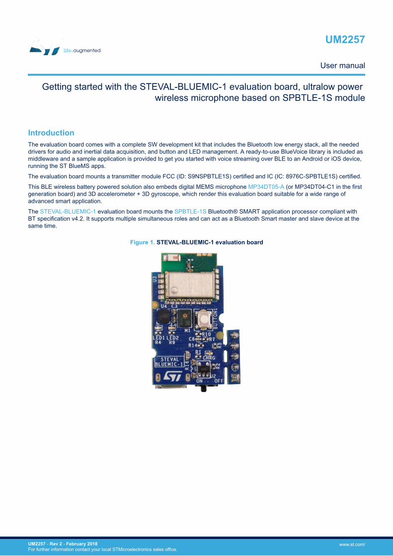
1.1.2 Evaluation kitThe STEVAL-BLUEMIC-1 evaluation kit helps you to start prototyping a very low power solution to stream audioand inertial data over BLE, exploiting the single-mode system-on-chip BlueNRG-1.
Figure 2. STEVAL-BLUEMIC-1 evaluation kit
The evaluation kit contains:• an STEVAL-BLUEMIC-1 evaluation board
UM2257Getting started
UM2257 - Rev 2 page 2/35
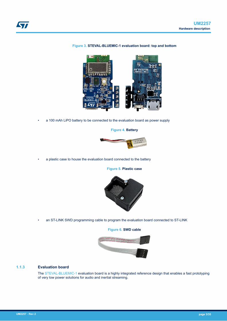
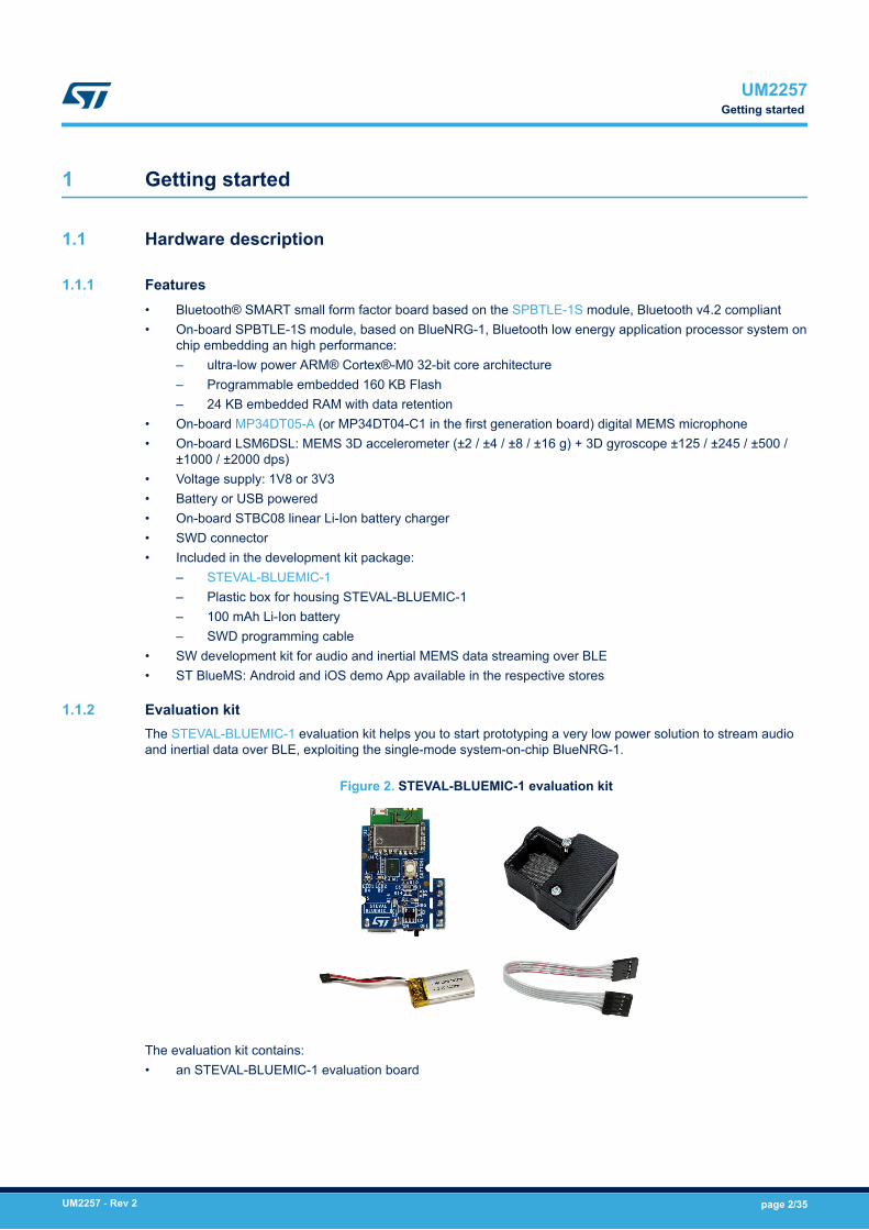
Figure 3. STEVAL-BLUEMIC-1 evaluation board: top and bottom
• a 100 mAh LiPO battery to be connected to the evaluation board as power supply
Figure 4. Battery
• a plastic case to house the evaluation board connected to the battery
Figure 5. Plastic case
• an ST-LINK SWD programming cable to program the evaluation board connected to ST-LINK
Figure 6. SWD cable
1.1.3 Evaluation boardThe STEVAL-BLUEMIC-1 evaluation board is a highly integrated reference design that enables a fast prototypingof very low power solutions for audio and inertial streaming.
UM2257Hardware description
UM2257 - Rev 2 page 3/35
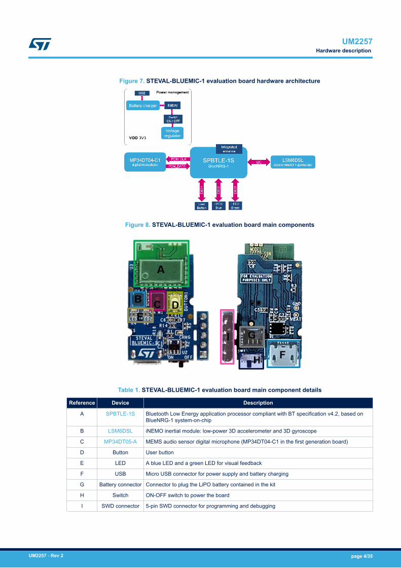
Figure 7. STEVAL-BLUEMIC-1 evaluation board hardware architecture
Figure 8. STEVAL-BLUEMIC-1 evaluation board main components
Table 1. STEVAL-BLUEMIC-1 evaluation board main component details
Reference Device Description
A SPBTLE-1S Bluetooth Low Energy application processor compliant with BT specification v4.2, based onBlueNRG-1 system-on-chip
B LSM6DSL iNEMO inertial module: low-power 3D accelerometer and 3D gyroscope
C MP34DT05-A MEMS audio sensor digital microphone (MP34DT04-C1 in the first generation board)
D Button User button
E LED A blue LED and a green LED for visual feedback
F USB Micro USB connector for power supply and battery charging
G Battery connector Connector to plug the LiPO battery contained in the kit
H Switch ON-OFF switch to power the board
I SWD connector 5-pin SWD connector for programming and debugging
UM2257Hardware description
UM2257 - Rev 2 page 4/35
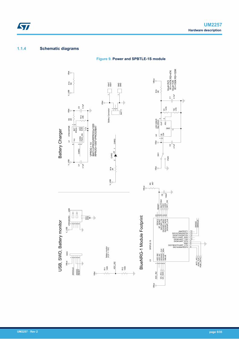
1.1.4 Schematic diagrams
Figure 9. Power and SPBTLE-1S moduleBa
ttery
Cha
rger
Blue
NR
G-1
Mod
ule
Foot
prin
t
USB
, SW
D, B
atte
ry m
onito
r
Max
200
mA
Vout
=3V3
R1=
147K
R2=
47K
Vout
=1V8
R1=
150K
R2=
120K
Batte
ry m
onito
r(4
.2V
-> 1
.8V)
VPR
OG
= 1
VIB
AT=(
VPR
OG
/RPR
OG
)x10
00R
PRO
G=1
000*
VPR
OG
/IBAT
V_U
SBVB
lue
VBat
VBlu
eVB
lue
VBlu
e
V_U
SB
V_U
SB
VBat
VBat
VBat
VBat
V_U
SBVB
at
I2C
_SD
AI2
C_S
CL
INT1
_AG
INT2
_AG
PDM
_CLK
PDM
_DAT
A
LED
1LE
D2
BUTT
ON
1
BATT
1
Batte
ry C
onne
ctor 1 2 3
C2
4.7u
F
VBAT
VBAT
1
C1
4.7u
F
R13
20K
R2
47K
R16
0R
R15
NC
GN
DG
ND
1
USB
USB
-MIC
RO
1 2 3 4
SH1SH2
5C
7
4.7µ
F
R14
2K
SW1
PWR
R5
4K7
R11
140K
CH
RG
21
SWD
1 2 3 4 5
U2
LDK1
20M
-R
EN3
GND2
IN1
ADJ
4O
UT
5
R12
105K
U1
STBC
08PM
R
PRO
G5
CH
RG
3
PAD 7BAT
1Vc
c6
GND 4
PWR
_ON
2C
9
4.7µ
F
C8
100n
FR
114
7K
U3
SPBT
LE-1
S
DIO14/ANATEST0 6
VBLU
E5
DIO
5/I2
C_S
DA
4D
IO4/
I2C
_CLK
3AD
C IN
12
ADC
IN2
1
DIO6/UART_RTS 9
DIO7/BOOT/UART_CTS 7
DIO8/UART_TXD 10DIO11/UART_RXD 11DIO9/TCK/SWTCK 12DIO10/TMS/SWTDI 13
ANATEST1 14DIO
0/SP
I_C
LK15
DIO
2/SP
I_M
OSI
16D
IO1/
SPI_
CS
18BT
_RES
ET19
DIO
A12
20
DIO
3/SP
I_M
ISO
17
GND 8
R8
0R
SWD
IOR
ESET
SWD
CLK
SWD
CLK
RES
ET
SWD
IO
ADC
_IN
2
ADC
_IN
2
CH
RG
CH
RG
UM2257Hardware description
UM2257 - Rev 2 page 5/35
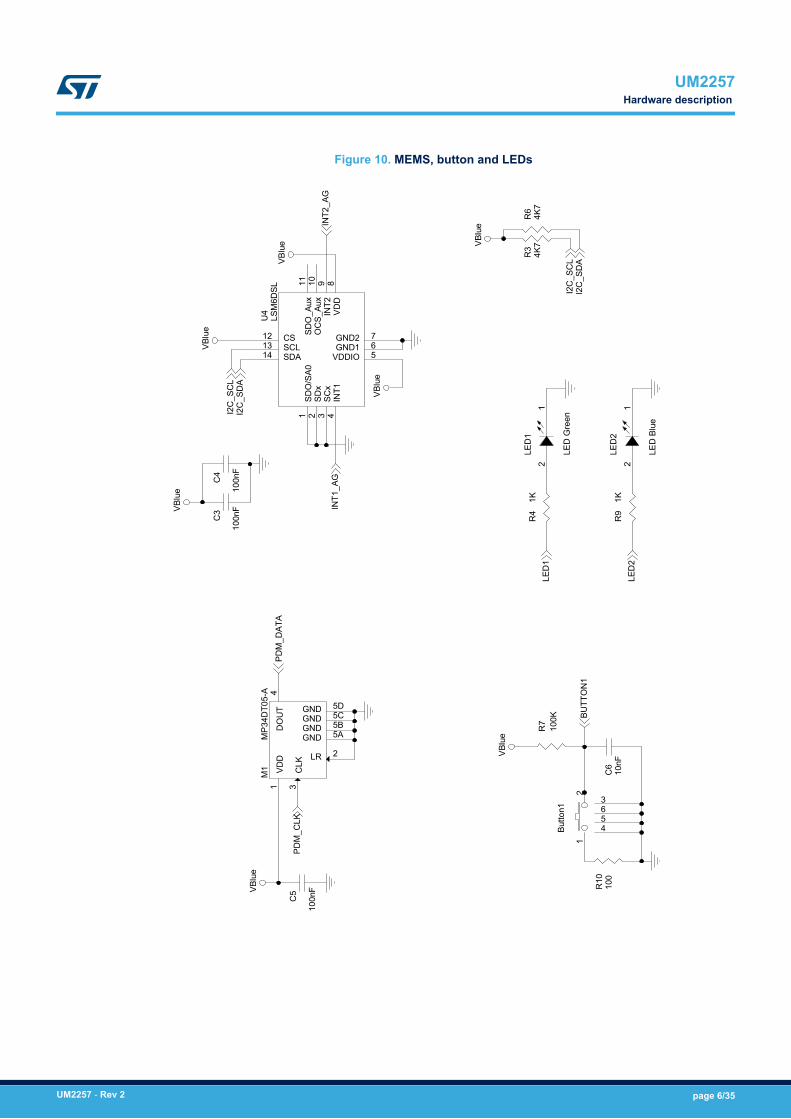
Figure 10. MEMS, button and LEDs
VBlu
e
VBlu
e
VBlu
e
VBlu
e
VBlu
e
VBlu
e
VBlu
e
PDM
_CLK
I2C
_SC
LI2
C_S
DA
INT1
_AG
INT2
_AG
PDM
_DAT
A
I2C
_SC
LI2
C_S
DA
BUTT
ON
1
LED
1
LED
2
R7
100K
R3
4K7
M1
MP3
4DT0
5-A
DO
UT
4
LR 2
GND 5A
VDD
1
CLK
3
GND 5B
GND 5DGND 5C
R10
100
R9
1K
R4
1K
C6
10nF
C4
100n
F
R6
4K7
C3
100n
F
Butto
n1
12
3
456
U4
LSM
6DSL
GND1 6VDDIO 5
INT1
4SC
x3
SDx
2SD
O/S
A01
VDD
8IN
T29
OC
S_Au
x10
SDO
_Aux
11
CS12SCL13
GND2 7
SDA14
C5
100n
F
LED
2
LED
Blu
e
21
LED
1
LED
Gre
en
21
UM2257Hardware description
UM2257 - Rev 2 page 6/35
1.2 Software description
1.2.1 OverviewThe STSW-BLUEMIC-1 is an evaluation software package that allows development of smart and innovativesolution using the SPBTLE-1S module.The software package includes the entire Bluetooth® low energy stack and protocols, complaint with the STSW-BLUENRG1-DK. It also contains a Board Support Package that offers a complete set of APIs for digital MEMSmicrophone, 3-axis accelerometer and gyroscope, button and LED management.The latter is based on BlueNRG-1, a very low power Bluetooth low energy single mode system-on-chipembedding a high performance, ultra-low power 32-bit ARM® Cortex®-M0, with 160 kB of Flash memory and 24kB of RAM.The BlueVoiceADPCM_BNRG1 binary library (available as middleware) provides a vendor specific profile forvoice streaming over Bluetooth® low energy; it includes all APIs needed for audio compression using the ITU-TG.726 ADPCM standard, packetization and streaming.The STSW-BLUEMIC-1 allows an STEVAL-BLUEMIC-1 evaluation board to act as a peripheral in a point-to-pointconnection with a mobile device running the ST BlueMS app, available for Android™ and iOS™. In thisconfiguration, the evaluation board streams the audio acquired from the on-board digital MEMS microphone(MP34DT05-A or MP34DT04-C1) or motion data acquired from the 3-axis accelerometer and gyroscope(LSM6DSL).
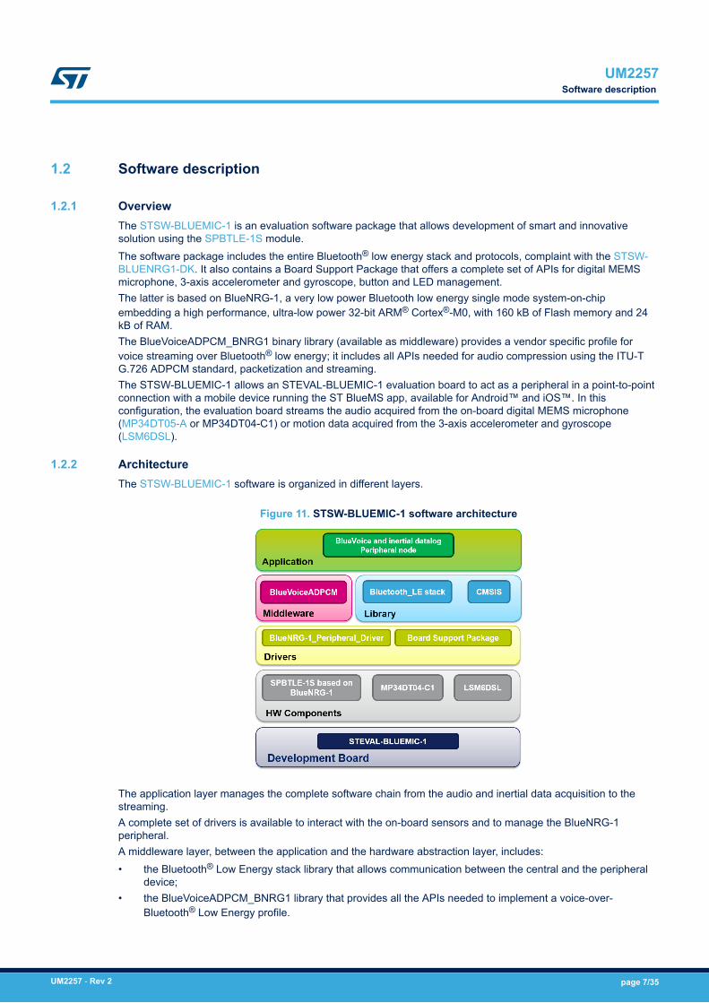
1.2.2 ArchitectureThe STSW-BLUEMIC-1 software is organized in different layers.
Figure 11. STSW-BLUEMIC-1 software architecture
The application layer manages the complete software chain from the audio and inertial data acquisition to thestreaming.A complete set of drivers is available to interact with the on-board sensors and to manage the BlueNRG-1peripheral.A middleware layer, between the application and the hardware abstraction layer, includes:• the Bluetooth® Low Energy stack library that allows communication between the central and the peripheral
device;• the BlueVoiceADPCM_BNRG1 library that provides all the APIs needed to implement a voice-over-
Bluetooth® Low Energy profile.
UM2257Software description
UM2257 - Rev 2 page 7/35
1.2.3 Folder structure
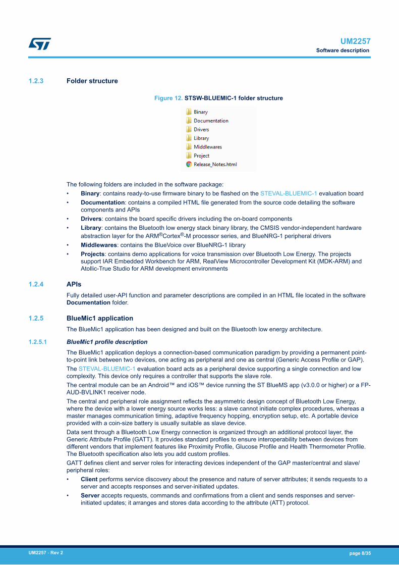
Figure 12. STSW-BLUEMIC-1 folder structure
The following folders are included in the software package:• Binary: contains ready-to-use firmware binary to be flashed on the STEVAL-BLUEMIC-1 evaluation board• Documentation: contains a compiled HTML file generated from the source code detailing the software
components and APIs• Drivers: contains the board specific drivers including the on-board components• Library: contains the Bluetooth low energy stack binary library, the CMSIS vendor-independent hardware
abstraction layer for the ARM®Cortex®-M processor series, and BlueNRG-1 peripheral drivers• Middlewares: contains the BlueVoice over BlueNRG-1 library• Projects: contains demo applications for voice transmission over Bluetooth Low Energy. The projects
support IAR Embedded Workbench for ARM, RealView Microcontroller Development Kit (MDK-ARM) andAtollic-True Studio for ARM development environments
1.2.4 APIsFully detailed user-API function and parameter descriptions are compiled in an HTML file located in the softwareDocumentation folder.
1.2.5 BlueMic1 applicationThe BlueMic1 application has been designed and built on the Bluetooth low energy architecture.
1.2.5.1 BlueMic1 profile description
The BlueMic1 application deploys a connection-based communication paradigm by providing a permanent point-to-point link between two devices, one acting as peripheral and one as central (Generic Access Profile or GAP).The STEVAL-BLUEMIC-1 evaluation board acts as a peripheral device supporting a single connection and lowcomplexity. This device only requires a controller that supports the slave role.The central module can be an Android™ and iOS™ device running the ST BlueMS app (v3.0.0 or higher) or a FP-AUD-BVLINK1 receiver node.The central and peripheral role assignment reflects the asymmetric design concept of Bluetooth Low Energy,where the device with a lower energy source works less: a slave cannot initiate complex procedures, whereas amaster manages communication timing, adaptive frequency hopping, encryption setup, etc. A portable deviceprovided with a coin-size battery is usually suitable as slave device.Data sent through a Bluetooth Low Energy connection is organized through an additional protocol layer, theGeneric Attribute Profile (GATT). It provides standard profiles to ensure interoperability between devices fromdifferent vendors that implement features like Proximity Profile, Glucose Profile and Health Thermometer Profile.The Bluetooth specification also lets you add custom profiles.GATT defines client and server roles for interacting devices independent of the GAP master/central and slave/peripheral roles:• Client performs service discovery about the presence and nature of server attributes; it sends requests to a
server and accepts responses and server-initiated updates.• Server accepts requests, commands and confirmations from a client and sends responses and server-
initiated updates; it arranges and stores data according to the attribute (ATT) protocol.
UM2257Software description
UM2257 - Rev 2 page 8/35
In a mono-directional audio streaming asymmetric system, the device with voice data is the one with amicrophone and is therefore considered the server. The client device sends requests to the server and acceptsserver-initiated updates containing audio data.Audio data transmission is based on periodic server-to-client notifications which do not require a request orresponse from the receiving device. Server-initiated updates are sent as asynchronous notification packets whichinclude the handle of a characteristic along with its current value.According to the Bluetooth specification, the peripheral enters advertising mode at start-up and sendsadvertisement packets at relatively long intervals. The central unit enters discovery mode and sends a connectionrequest on reception of an advertisement packet from a slave device. After connection, notifications carryingaudio data are periodically sent from the server to the client.
1.2.5.2 BlueMic1 service
The Attribute Protocol (ATT) is used by GATT as a transport protocol for exchanging data between devices. Thesmallest entities defined by ATT (named attributes) are addressable pieces of information that may contain userdata or meta-information on the attribute architecture, stored in the server and exchanged between client andserver.GATT server attributes are organized as a sequence of services, each one starting with a service declarationattribute marking its beginning. Each service groups one or more characteristics and each characteristic caninclude zero or more descriptors.Since audio streaming is not part of the predefined set of profiles, the STSW-BLUEMIC-1 application defines avendor-specific service named BlueMic1 Service based on an Audio characteristic to expose actual compressedaudio data and a Sync characteristic to expose collateral information to implement a synchronization mechanismand an inertial characteristic to expose 3-axis accelerometer and gyroscope raw data.
Table 2. BlueMic1 UUID summary table
UUID name UUID
bluemic1_service_uuid 00000000-0001-11e1-9ab4-0002a5d5c51b
audio_adpcm_char_uuid 08000000-0001-11e1-ac36-0002a5d5c51b
audio_adpcm_sync_char_uuid 40000000-0001-11e1-ac36-0002a5d5c51b
acc_gyr_char_uuid 00E00000-0001-11e1-ac36-0002a5d5c51b
Given the service hierarchical architecture, further characteristics may be added to the BlueMic1 service, such asconfiguration of parameters like volume, enabling/disabling of processing algorithms, etc.
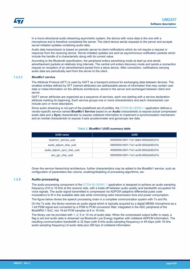
1.2.6 Audio processingThe audio processing component of the STSW-BLUEMIC-1 application is designed to achieve an audio samplingfrequency of 8 or 16 kHz at the receiver side, with a trade-off between audio quality and bandwidth occupation forvoice signals. The audio signal transmitted is compressed via ADPCM (adaptive differential pulse codemodulation) to fit in the available data rate while minimizing radio transmission time and power consumption.The figure below shows the speech processing chain in a complete communication system with Tx and Rx.On the Tx side, the library receives an audio signal which is typically acquired by a digital MEMS microphone as a1-bit PDM signal and converted by a PDM to PCM conversion filter, integrated in the ADC peripheral of theBlueNRG-1 SoC, into 16-bit PCM samples at 8 or 16 kHz.The library can be provided with 1, 2, 5 or 10 ms of audio data. When the compressed output buffer is ready, aflag is set and audio data is streamed via Bluetooth Low Energy together with collateral ADPCM information. Theresulting communication bandwidth is 32 kbps (with 8 kHz audio sampling frequency) or 64 kbps (with 16 kHzaudio sampling frequency) of audio data plus 300 bps of collateral information.
UM2257Software description
UM2257 - Rev 2 page 9/35
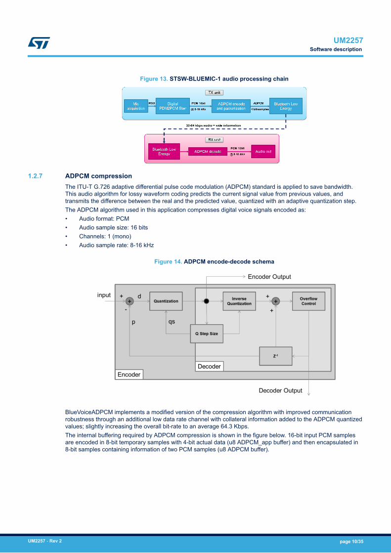
Figure 13. STSW-BLUEMIC-1 audio processing chain
1.2.7 ADPCM compressionThe ITU-T G.726 adaptive differential pulse code modulation (ADPCM) standard is applied to save bandwidth.This audio algorithm for lossy waveform coding predicts the current signal value from previous values, andtransmits the difference between the real and the predicted value, quantized with an adaptive quantization step.The ADPCM algorithm used in this application compresses digital voice signals encoded as:• Audio format: PCM• Audio sample size: 16 bits• Channels: 1 (mono)• Audio sample rate: 8-16 kHz
Figure 14. ADPCM encode-decode schema
BlueVoiceADPCM implements a modified version of the compression algorithm with improved communicationrobustness through an additional low data rate channel with collateral information added to the ADPCM quantizedvalues; slightly increasing the overall bit-rate to an average 64.3 Kbps.The internal buffering required by ADPCM compression is shown in the figure below. 16-bit input PCM samplesare encoded in 8-bit temporary samples with 4-bit actual data (u8 ADPCM_app buffer) and then encapsulated in8-bit samples containing information of two PCM samples (u8 ADPCM buffer).
UM2257Software description
UM2257 - Rev 2 page 10/35
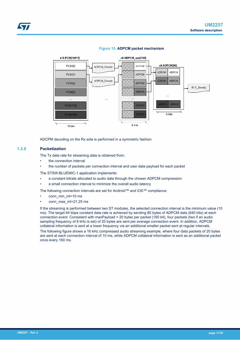
Figure 15. ADPCM packet mechanism
ADCPM decoding on the Rx side is performed in a symmetric fashion.
1.2.8 PacketizationThe Tx data rate for streaming data is obtained from:• the connection interval• the number of packets per connection interval and user data payload for each packet
The STSW-BLUEMIC-1 application implements:• a constant bitrate allocated to audio data through the chosen ADPCM compression• a small connection interval to minimize the overall audio latency
The following connection intervals are set for Android™ and iOS™ compliance:• conn_min_int=10 ms• conn_max_int=21.25 ms
If the streaming is performed between two ST modules, the selected connection interval is the minimum value (10ms). The target 64 kbps constant data rate is achieved by sending 80 bytes of ADPCM data (640 bits) at eachconnection event. Consistent with maxPayload = 20 bytes per packet (160 bit), four packets (two if an audiosampling frequency of 8 kHz is set) of 20 bytes are sent per average connection event. In addition, ADPCMcollateral information is sent at a lower frequency via an additional smaller packet sent at regular intervals.The following figure shows a 16 kHz compressed audio streaming example, where four data packets of 20 bytesare sent at each connection interval of 10 ms, while ADPCM collateral information is sent as an additional packetonce every 160 ms.
UM2257Software description
UM2257 - Rev 2 page 11/35
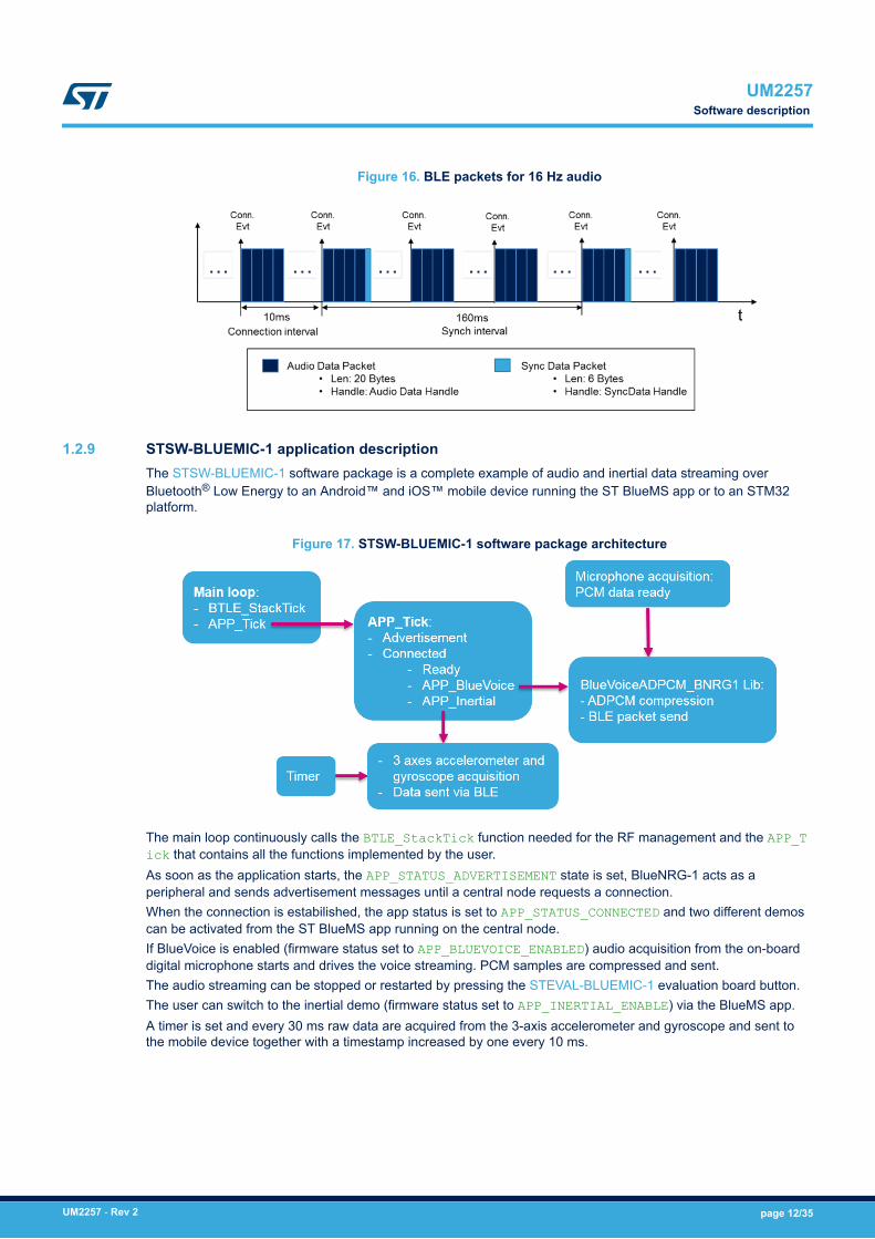
Figure 16. BLE packets for 16 Hz audio
1.2.9 STSW-BLUEMIC-1 application descriptionThe STSW-BLUEMIC-1 software package is a complete example of audio and inertial data streaming overBluetooth® Low Energy to an Android™ and iOS™ mobile device running the ST BlueMS app or to an STM32platform.
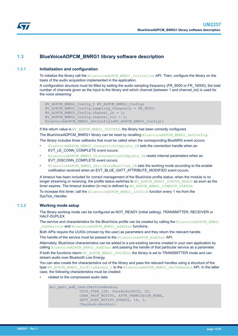
Figure 17. STSW-BLUEMIC-1 software package architecture
The main loop continuously calls the BTLE_StackTick function needed for the RF management and the APP_Tick that contains all the functions implemented by the user.As soon as the application starts, the APP_STATUS_ADVERTISEMENT state is set, BlueNRG-1 acts as aperipheral and sends advertisement messages until a central node requests a connection.When the connection is estabilished, the app status is set to APP_STATUS_CONNECTED and two different demoscan be activated from the ST BlueMS app running on the central node.If BlueVoice is enabled (firmware status set to APP_BLUEVOICE_ENABLED) audio acquisition from the on-boarddigital microphone starts and drives the voice streaming. PCM samples are compressed and sent.The audio streaming can be stopped or restarted by pressing the STEVAL-BLUEMIC-1 evaluation board button.The user can switch to the inertial demo (firmware status set to APP_INERTIAL_ENABLE) via the BlueMS app.A timer is set and every 30 ms raw data are acquired from the 3-axis accelerometer and gyroscope and sent tothe mobile device together with a timestamp increased by one every 10 ms.
UM2257Software description
UM2257 - Rev 2 page 12/35
1.3 BlueVoiceADPCM_BNRG1 library software description
1.3.1 Initialization and configurationTo initialize the library call the BluevoiceADPCM_BNRG1_Initialize API. Then, configure the library on thebasis of the audio acquisition implemented in the application.A configuration structure must be filled by setting the audio sampling frequency (FR_8000 or FR_16000), the totalnumber of channels given as the input to the library and which channel (between 1 and channel_tot) is used forthe voice streaming:
BV_ADPCM_BNRG1_Config_t BV_ADPCM_BNRG1_Config; BV_ADPCM_BNRG1_Config.sampling_frequency = FR_8000; BV_ADPCM_BNRG1_Config.channel_in = 1; BV_ADPCM_BNRG1_Config.channel_tot = 1; BluevoiceADPCM_BNRG1_SetConfig(&BV_ADPCM_BNRG1_Config);
If the return value is BV_ADPCM_BNRG1_SUCCESS, the library has been correctly configured.The BlueVoiceADPCM_BNRG1 library can be reset by recalling BluevoiceADPCM_BNRG1_SetConfig.The library includes three callbacks that must be called when the corresponding BlueNRG event occurs:• BluevoiceADPCM_BNRG1_ConnectionComplete_CB sets the connection handle when an
EVT_LE_CONN_COMPLETE event occurs;• BluevoiceADPCM_BNRG1_DisconnectionComplete_CB resets internal parameters when an
EVT_DISCONN_COMPLETE event occurs;• BluevoiceADPCM_BNRG1_AttributeModified_CB sets the working mode according to the enable
notification received when an EVT_BLUE_GATT_ATTRIBUTE_MODIFIED event occurs.
A timeout has been included for correct management of the BlueVoice profile status; when the module is nolonger streaming or receiving, the profile status switches to BV_ADPCM_BNRG1_STATUS_READY as soon as thetimer expires. The timeout duration (in ms) is defined by BV_ADPCM_BNRG1_TIMEOUT_STATUS.To increase this timer, call the BluevoiceADPCM_BNRG1_IncTick function every 1 ms from theSysTick_Handler.
1.3.2 Working mode setupThe library working mode can be configured as NOT_READY (initial setting), TRANSMITTER, RECEIVER orHALF-DUPLEX.The service and characteristics for the BlueVoice profile can be created by calling the BluevoiceADPCM_BNRG1_AddService and BluevoiceADPCM_BNRG1_AddChar functions.Both APIs require the UUIDs (chosen by the user) as parameters and they return the relevant handle.The handle of the service must be passed to the BluevoiceADPCM_AddChar API.Alternately, BlueVoice characteristics can be added to a pre-existing service created in your own application bycalling BluevoiceADPCM_BNRG1_AddChar and passing the handle of that particular service as a parameter.If both the functions return BV_ADPCM_BNRG1_SUCCESS, the library is set to TRANSMITTER mode and canstream audio over Bluetooth Low Energy.You can also create the characteristics out of the library and pass the relevant handles using a structure of thetype BV_ADPCM_BNRG1_ProfileHandle_t to the BluevoiceADPCM_BNRG1_SetTxHandle API. In the lattercase, the following characteristics must be created:• related to the compressed audio data
aci_gatt_add_char(ServiceHandle, UUID_TYPE_128, CharAudioUUID, 20, CHAR_PROP_NOTIFY, ATTR_PERMISSION_NONE, GATT_DONT_NOTIFY_EVENTS, 16, 1, CharAudioHandle);
UM2257BlueVoiceADPCM_BNRG1 library software description
UM2257 - Rev 2 page 13/35
• to send collateral information for synchronization mechanism implementation
aci_gatt_add_char(ServiceHandle, UUID_TYPE_128, CharAudioSyncUUID, 6, CHAR_PROP_NOTIFY, ATTR_PERMISSION_NONE, GATT_DONT_NOTIFY_EVENTS, 16, 1, CharAudioSyncHandle);
You can choose to not create the BlueVoice Service and the module is not able to transmit audio.This node can still function as a RECEIVER; however, if the connected module exports the BlueVoice profile; youmust set the handle of the BlueVoice service and characteristics exported by the transmitter module through the BluevoiceADPCM_BNRG1_SetRxHandle API and enable notifications on the other node by calling the BluevoiceADPCM_BNRG1_EnableNotification function.If both the TRANSMITTER and RECEIVER procedures are performed, the module acts as transmitter andreceiver and the working mode is set to HALF-DUPLEX, creating a half-duplex link over Bluetooth Low Energy.
1.3.3 Audio signal injectionThe BlueVoiceADPCM_BNRG1 library receives audio PCM input samples.The BluevoiceADPCM_BNRG1_AudioIn function accepts parameters from a PCM buffer, containing all theacquired audio channels (channel_tot according to the previous library configuration) and the number of PCMsamples (for each channel) given as input. An amount of data equal to 1, 2, 5 or 10 ms is accepted, otherwise anBV_ADPCM_BNRG1_PCM_SAMPLES_ERR is returned.The library compresses received PCM input samples; when 10 ms of audio is compressed, the BluevoiceADPCM_BNRG1_AudioIn API returns BV_ADPCM_BNRG1_OUT_BUF_READY.
1.3.4 Compressed audio streamingOn the transmitter side, the BlueVoiceADPCM_BNRG1 library gathers compressed data in an internal doublebuffer. For every 10 ms of audio, the BluevoiceADPCM_BNRG1_AudioIn function returns BV_ADPCM_BNRG1_OUT_BUF_READY to signal output data can be send via Bluetooth Low Energy by calling the BluevoiceADPCM_BNRG1_SendData API.If the audio sampling frequency is set to 8 kHz, two 20-byte packets are sent every 10 ms (according to theconnection interval); if the frequency is 16 kHz, four 20-byte packets are sent.On the receiver side, compressed audio is received from a notification through aEVT_BLUE_GATT_NOTIFICATION event and passed to the BluevoiceADPCM_BNRG1_ParseData functionthat decompresses the data and returns a PCM buffer. This API is used to parse both audio and collateralinformation data.
UM2257BlueVoiceADPCM_BNRG1 library software description
UM2257 - Rev 2 page 14/35
2 System setup
Two types of demos can be set up using an STEVAL-BLUEMIC-1 evaluation board:1. unidirectional streaming of inertial data and audio at a sampling frequency of 8 kHz from the STEVAL-
BLUEMIC-1 to an Android™ or iOS™ device running the ST BlueMS app (v3.0.0 or higher);2. unidirectional audio streaming at a sampling frequency of 8 or 16 kHz from the STEVAL-BLUEMIC-1 to the
receiver node of the FP-AUD-BVLINK1 application available on www.st.com.
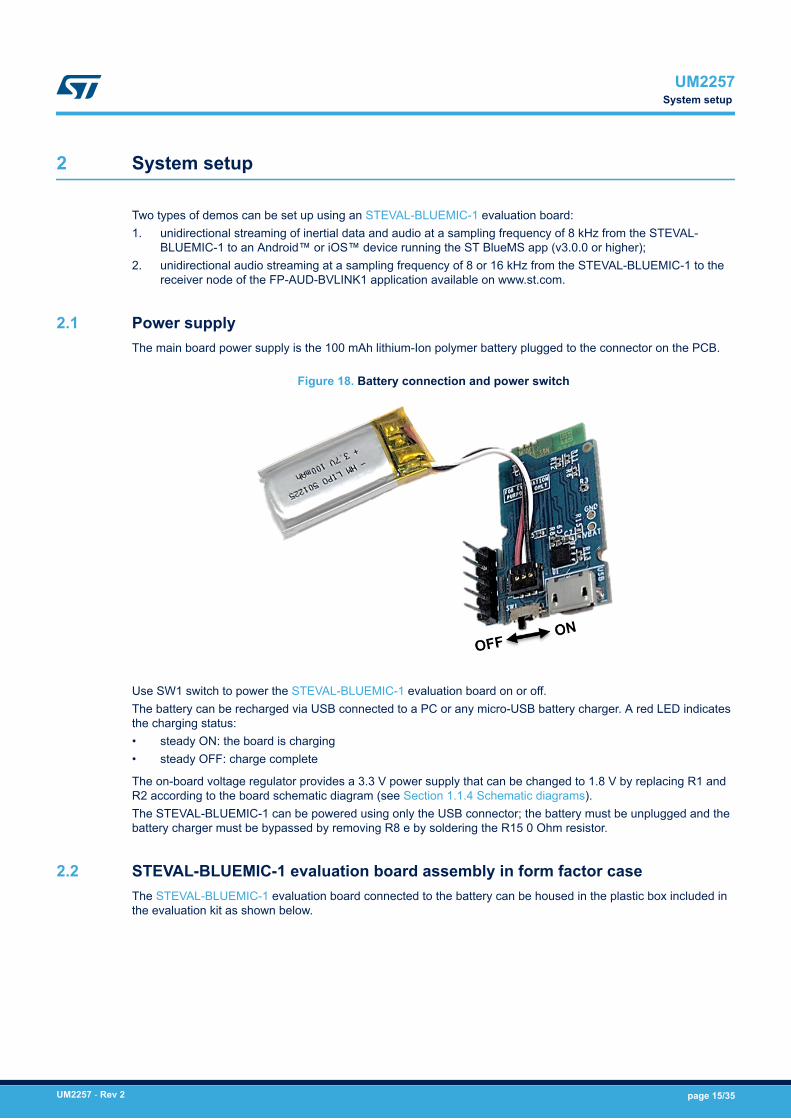
2.1 Power supplyThe main board power supply is the 100 mAh lithium-Ion polymer battery plugged to the connector on the PCB.
Figure 18. Battery connection and power switch
Use SW1 switch to power the STEVAL-BLUEMIC-1 evaluation board on or off.The battery can be recharged via USB connected to a PC or any micro-USB battery charger. A red LED indicatesthe charging status:• steady ON: the board is charging• steady OFF: charge complete
The on-board voltage regulator provides a 3.3 V power supply that can be changed to 1.8 V by replacing R1 andR2 according to the board schematic diagram (see Section 1.1.4 Schematic diagrams).The STEVAL-BLUEMIC-1 can be powered using only the USB connector; the battery must be unplugged and thebattery charger must be bypassed by removing R8 e by soldering the R15 0 Ohm resistor.
2.2 STEVAL-BLUEMIC-1 evaluation board assembly in form factor caseThe STEVAL-BLUEMIC-1 evaluation board connected to the battery can be housed in the plastic box included inthe evaluation kit as shown below.
UM2257System setup
UM2257 - Rev 2 page 15/35
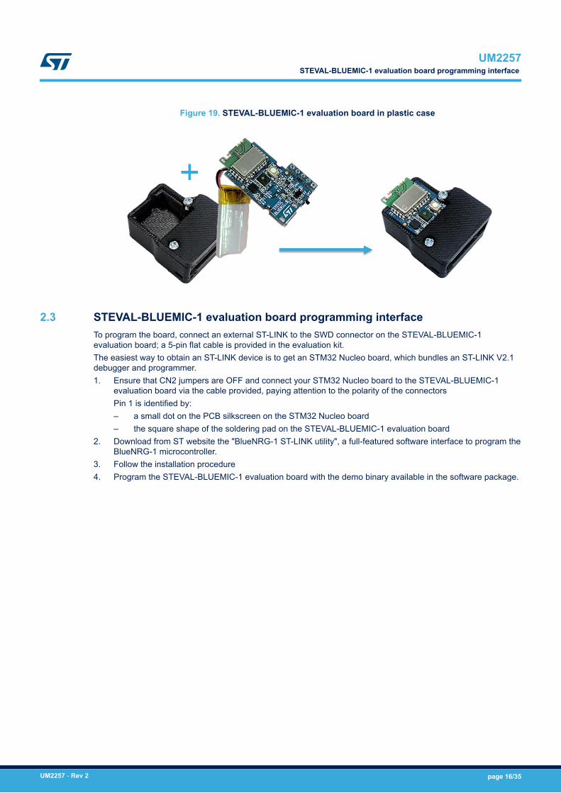
Figure 19. STEVAL-BLUEMIC-1 evaluation board in plastic case
2.3 STEVAL-BLUEMIC-1 evaluation board programming interfaceTo program the board, connect an external ST-LINK to the SWD connector on the STEVAL-BLUEMIC-1evaluation board; a 5-pin flat cable is provided in the evaluation kit.The easiest way to obtain an ST-LINK device is to get an STM32 Nucleo board, which bundles an ST-LINK V2.1debugger and programmer.1. Ensure that CN2 jumpers are OFF and connect your STM32 Nucleo board to the STEVAL-BLUEMIC-1
evaluation board via the cable provided, paying attention to the polarity of the connectorsPin 1 is identified by:– a small dot on the PCB silkscreen on the STM32 Nucleo board– the square shape of the soldering pad on the STEVAL-BLUEMIC-1 evaluation board
2. Download from ST website the "BlueNRG-1 ST-LINK utility", a full-featured software interface to program theBlueNRG-1 microcontroller.
3. Follow the installation procedure4. Program the STEVAL-BLUEMIC-1 evaluation board with the demo binary available in the software package.
UM2257STEVAL-BLUEMIC-1 evaluation board programming interface
UM2257 - Rev 2 page 16/35
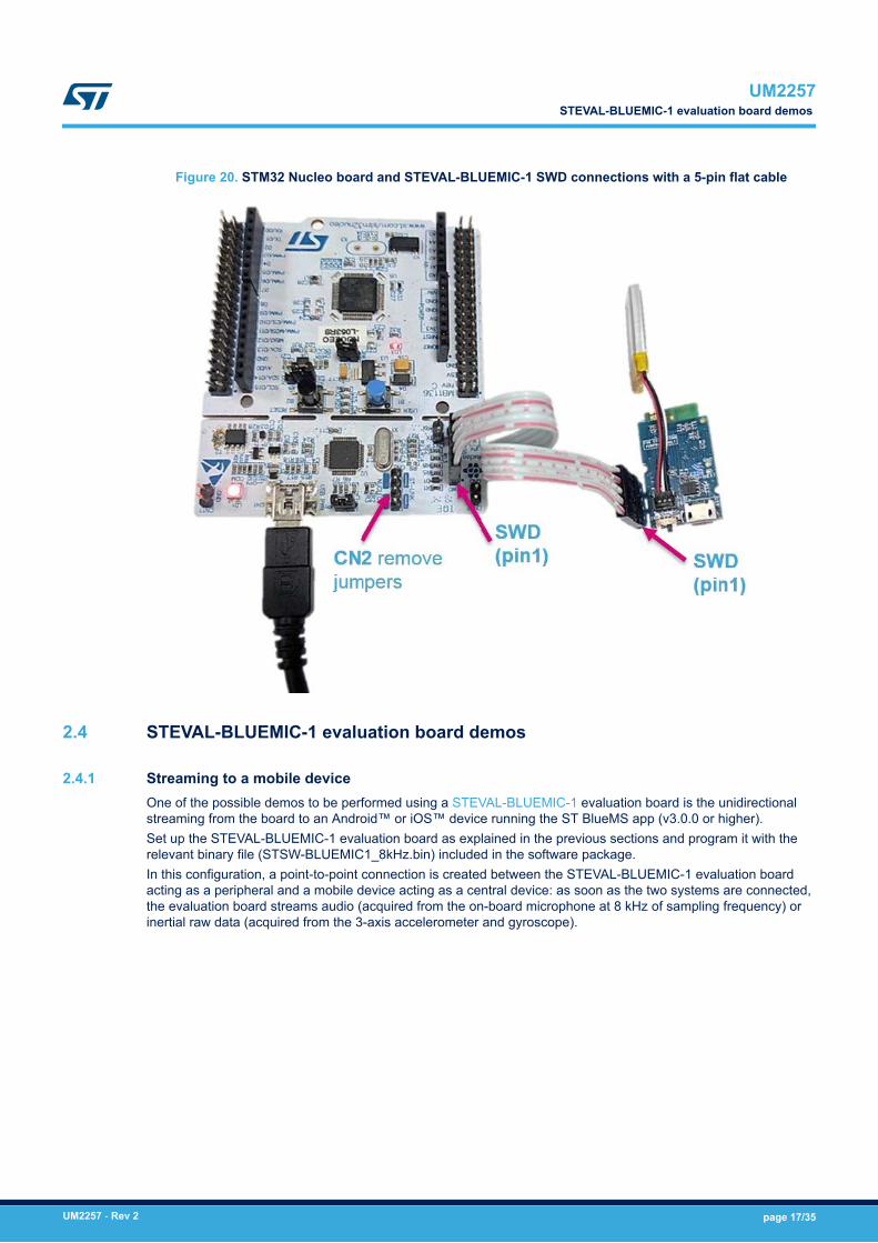
Figure 20. STM32 Nucleo board and STEVAL-BLUEMIC-1 SWD connections with a 5-pin flat cable
2.4 STEVAL-BLUEMIC-1 evaluation board demos
2.4.1 Streaming to a mobile deviceOne of the possible demos to be performed using a STEVAL-BLUEMIC-1 evaluation board is the unidirectionalstreaming from the board to an Android™ or iOS™ device running the ST BlueMS app (v3.0.0 or higher).Set up the STEVAL-BLUEMIC-1 evaluation board as explained in the previous sections and program it with therelevant binary file (STSW-BLUEMIC1_8kHz.bin) included in the software package.In this configuration, a point-to-point connection is created between the STEVAL-BLUEMIC-1 evaluation boardacting as a peripheral and a mobile device acting as a central device: as soon as the two systems are connected,the evaluation board streams audio (acquired from the on-board microphone at 8 kHz of sampling frequency) orinertial raw data (acquired from the 3-axis accelerometer and gyroscope).
UM2257STEVAL-BLUEMIC-1 evaluation board demos
UM2257 - Rev 2 page 17/35
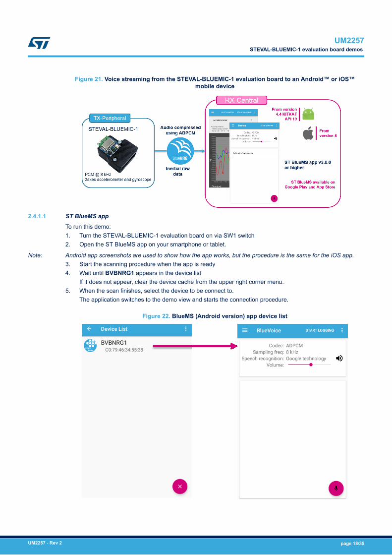
Figure 21. Voice streaming from the STEVAL-BLUEMIC-1 evaluation board to an Android™ or iOS™mobile device
2.4.1.1 ST BlueMS app
To run this demo:1. Turn the STEVAL-BLUEMIC-1 evaluation board on via SW1 switch2. Open the ST BlueMS app on your smartphone or tablet.
Note: Android app screenshots are used to show how the app works, but the procedure is the same for the iOS app.3. Start the scanning procedure when the app is ready4. Wait until BVBNRG1 appears in the device list
If it does not appear, clear the device cache from the upper right corner menu.5. When the scan finishes, select the device to be connect to.
The application switches to the demo view and starts the connection procedure.
Figure 22. BlueMS (Android version) app device list
UM2257STEVAL-BLUEMIC-1 evaluation board demos
UM2257 - Rev 2 page 18/35
2.4.1.2 BlueVoice page
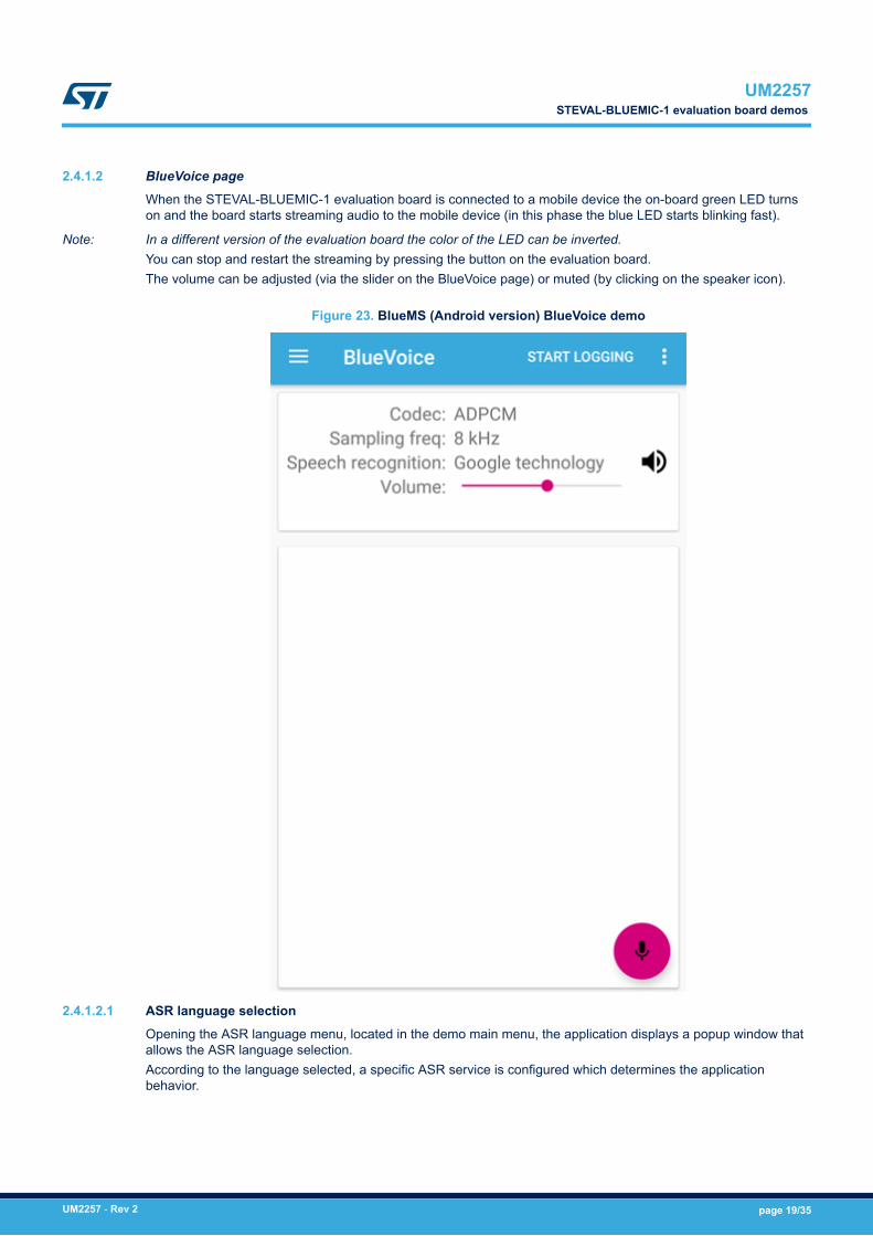
When the STEVAL-BLUEMIC-1 evaluation board is connected to a mobile device the on-board green LED turnson and the board starts streaming audio to the mobile device (in this phase the blue LED starts blinking fast).
Note: In a different version of the evaluation board the color of the LED can be inverted.You can stop and restart the streaming by pressing the button on the evaluation board.The volume can be adjusted (via the slider on the BlueVoice page) or muted (by clicking on the speaker icon).
Figure 23. BlueMS (Android version) BlueVoice demo
2.4.1.2.1 ASR language selectionOpening the ASR language menu, located in the demo main menu, the application displays a popup window thatallows the ASR language selection.According to the language selected, a specific ASR service is configured which determines the applicationbehavior.
UM2257STEVAL-BLUEMIC-1 evaluation board demos
UM2257 - Rev 2 page 19/35
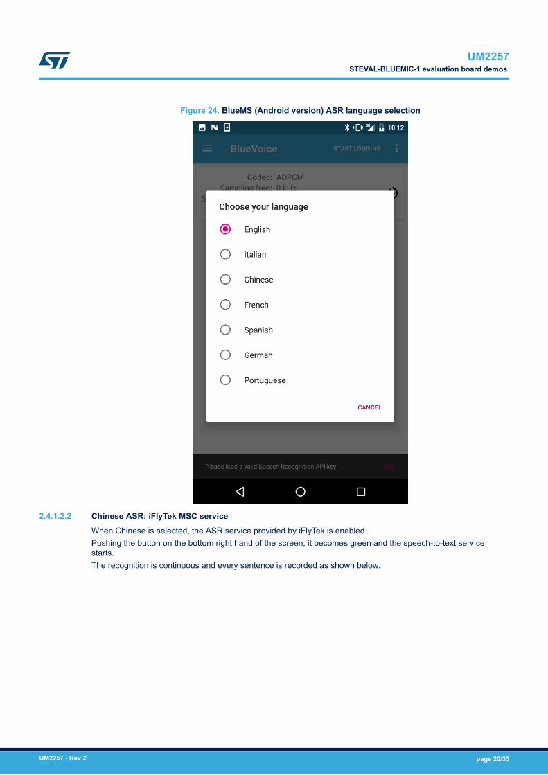
Figure 24. BlueMS (Android version) ASR language selection
2.4.1.2.2 Chinese ASR: iFlyTek MSC serviceWhen Chinese is selected, the ASR service provided by iFlyTek is enabled.Pushing the button on the bottom right hand of the screen, it becomes green and the speech-to-text servicestarts.The recognition is continuous and every sentence is recorded as shown below.
UM2257STEVAL-BLUEMIC-1 evaluation board demos
UM2257 - Rev 2 page 20/35
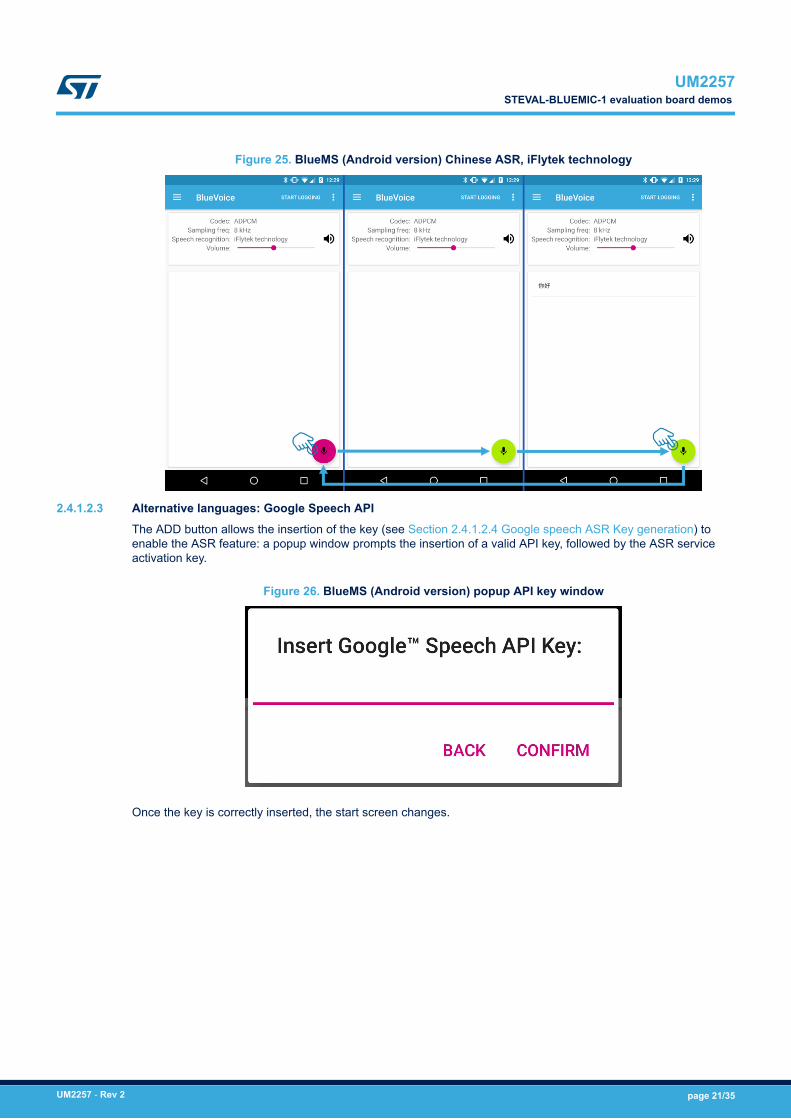
Figure 25. BlueMS (Android version) Chinese ASR, iFlytek technology
2.4.1.2.3 Alternative languages: Google Speech APIThe ADD button allows the insertion of the key (see Section 2.4.1.2.4 Google speech ASR Key generation) toenable the ASR feature: a popup window prompts the insertion of a valid API key, followed by the ASR serviceactivation key.
Figure 26. BlueMS (Android version) popup API key window
Once the key is correctly inserted, the start screen changes.
UM2257STEVAL-BLUEMIC-1 evaluation board demos
UM2257 - Rev 2 page 21/35
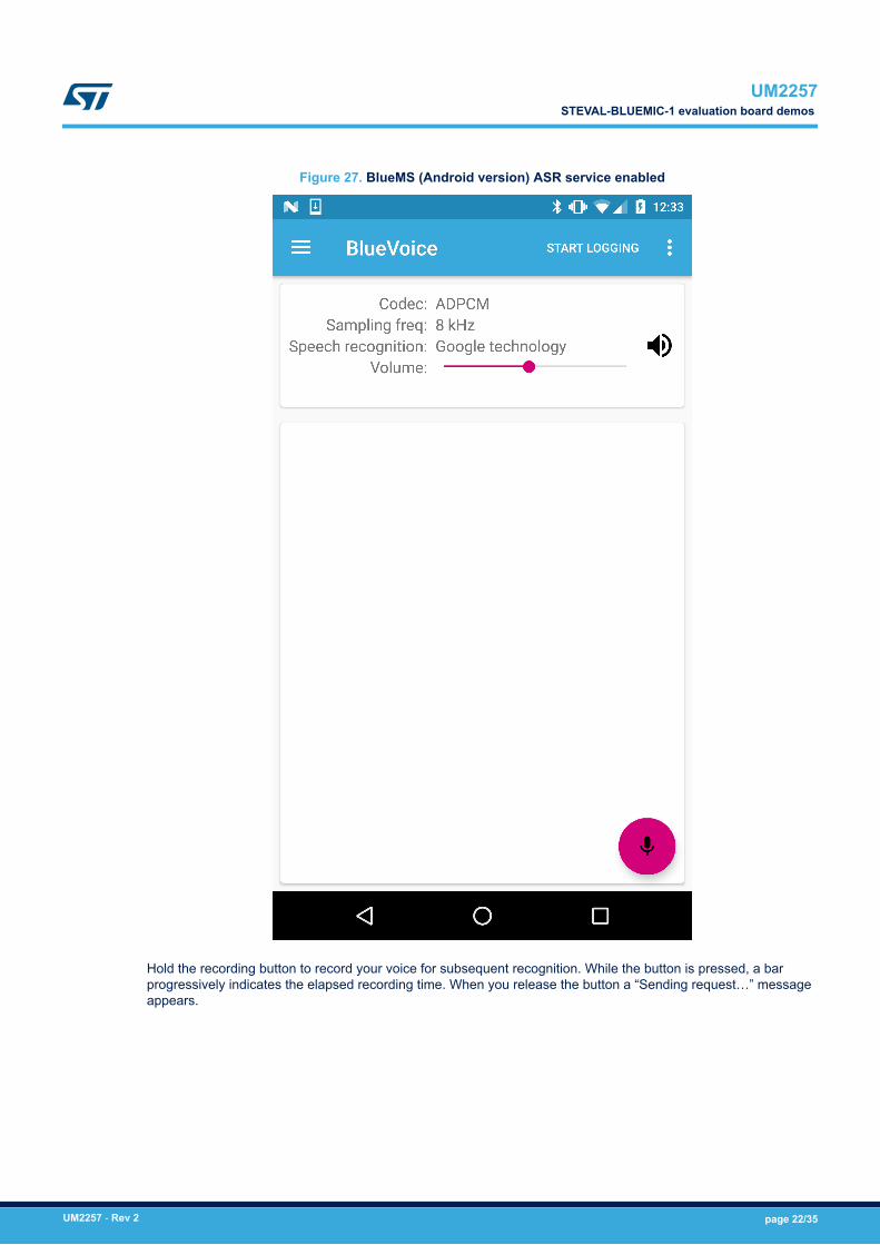
Figure 27. BlueMS (Android version) ASR service enabled
Hold the recording button to record your voice for subsequent recognition. While the button is pressed, a barprogressively indicates the elapsed recording time. When you release the button a “Sending request…” messageappears.
UM2257STEVAL-BLUEMIC-1 evaluation board demos
UM2257 - Rev 2 page 22/35
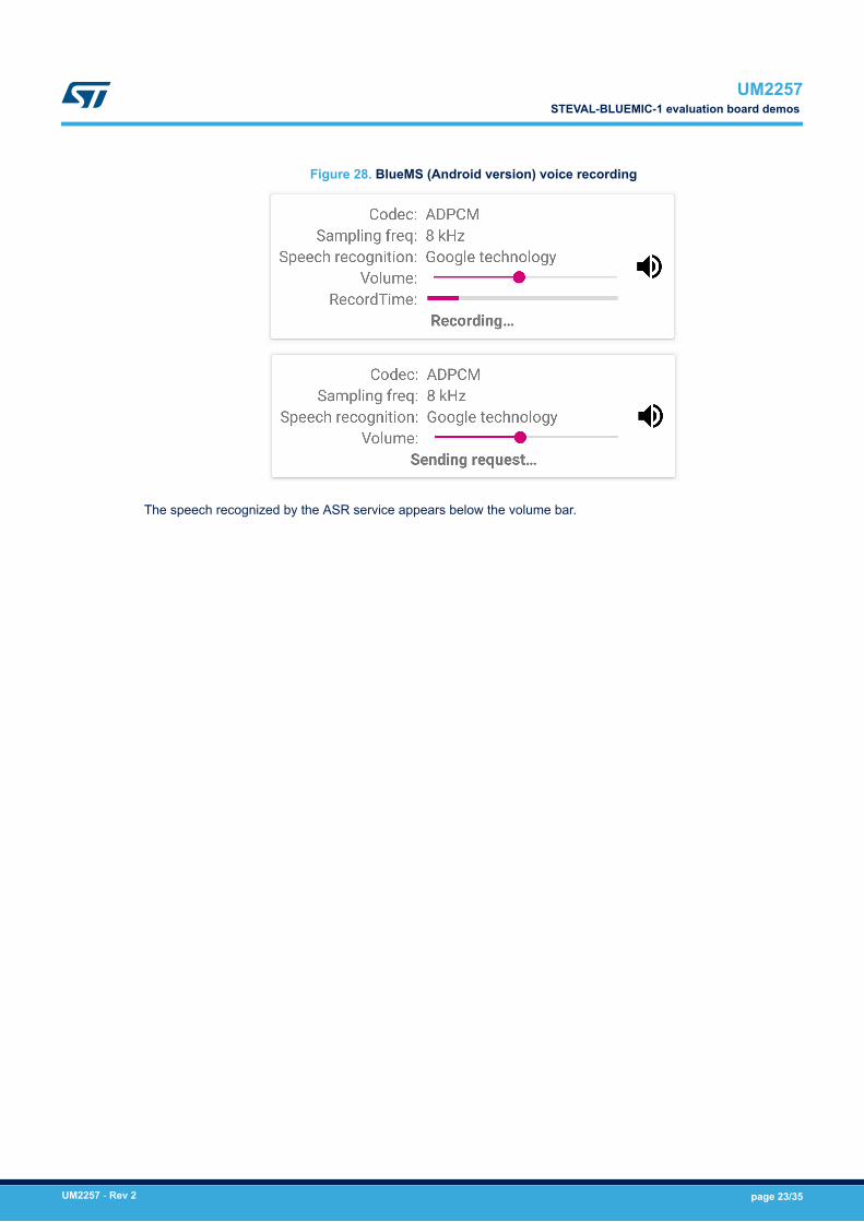
Figure 28. BlueMS (Android version) voice recording
The speech recognized by the ASR service appears below the volume bar.
UM2257STEVAL-BLUEMIC-1 evaluation board demos
UM2257 - Rev 2 page 23/35
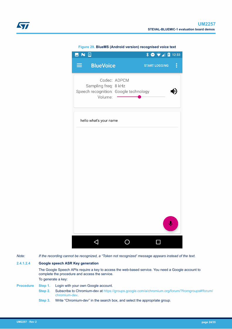
Figure 29. BlueMS (Android version) recognised voice text
Note: If the recording cannot be recognized, a “Token not recognized’ message appears instead of the text.
2.4.1.2.4 Google speech ASR Key generation
The Google Speech APIs require a key to access the web-based service. You need a Google account tocomplete the procedure and access the service.To generate a key:
Procedure Step 1. Login with your own Google account.Step 2. Subscribe to Chromium-dev at https://groups.google.com/a/chromium.org/forum/?fromgroups#!forum/
chromium-dev.Step 3. Write “Chromium-dev” in the search box, and select the appropriate group.
UM2257STEVAL-BLUEMIC-1 evaluation board demos
UM2257 - Rev 2 page 24/35
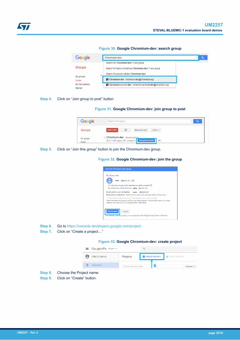
Figure 30. Google Chromium-dev: search group
Step 4. Click on “Join group to post” button
Figure 31. Google Chromium-dev: join group to post
Step 5. Click on “Join this group” button to join the Chromium-dev group.
Figure 32. Google Chromium-dev: join the group
Step 6. Go to https://console.developers.google.com/projectStep 7. Click on “Create a project…”
Figure 33. Google Chromium-dev: create project
Step 8. Choose the Project name.Step 9. Click on “Create” button.
UM2257STEVAL-BLUEMIC-1 evaluation board demos
UM2257 - Rev 2 page 25/35
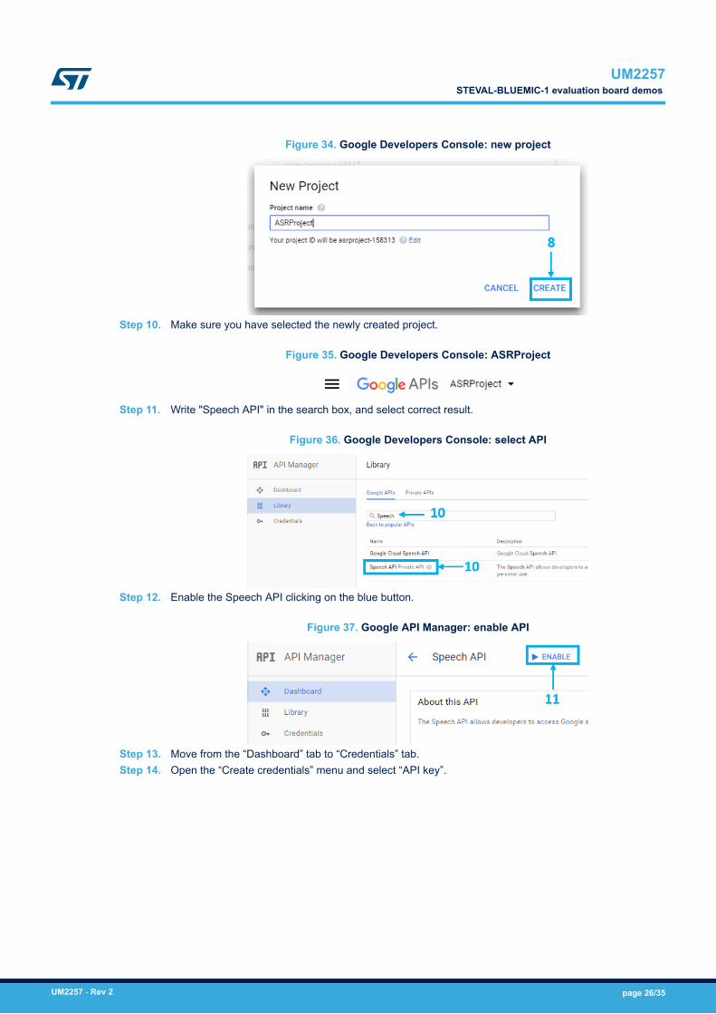
Figure 34. Google Developers Console: new project
Step 10. Make sure you have selected the newly created project.
Figure 35. Google Developers Console: ASRProject
Step 11. Write "Speech API" in the search box, and select correct result.
Figure 36. Google Developers Console: select API
Step 12. Enable the Speech API clicking on the blue button.
Figure 37. Google API Manager: enable API
Step 13. Move from the “Dashboard” tab to “Credentials” tab.Step 14. Open the “Create credentials” menu and select “API key”.
UM2257STEVAL-BLUEMIC-1 evaluation board demos
UM2257 - Rev 2 page 26/35
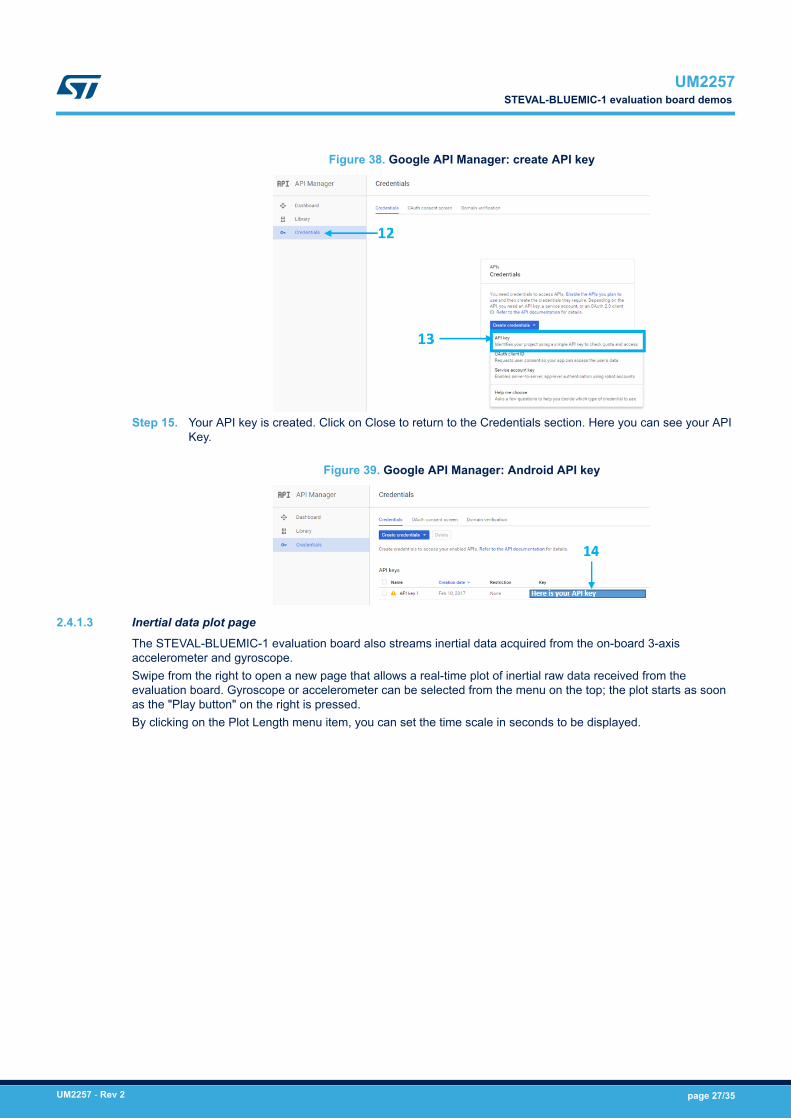
Figure 38. Google API Manager: create API key
Step 15. Your API key is created. Click on Close to return to the Credentials section. Here you can see your APIKey.
Figure 39. Google API Manager: Android API key
2.4.1.3 Inertial data plot page
The STEVAL-BLUEMIC-1 evaluation board also streams inertial data acquired from the on-board 3-axisaccelerometer and gyroscope.Swipe from the right to open a new page that allows a real-time plot of inertial raw data received from theevaluation board. Gyroscope or accelerometer can be selected from the menu on the top; the plot starts as soonas the "Play button" on the right is pressed.By clicking on the Plot Length menu item, you can set the time scale in seconds to be displayed.
UM2257STEVAL-BLUEMIC-1 evaluation board demos
UM2257 - Rev 2 page 27/35
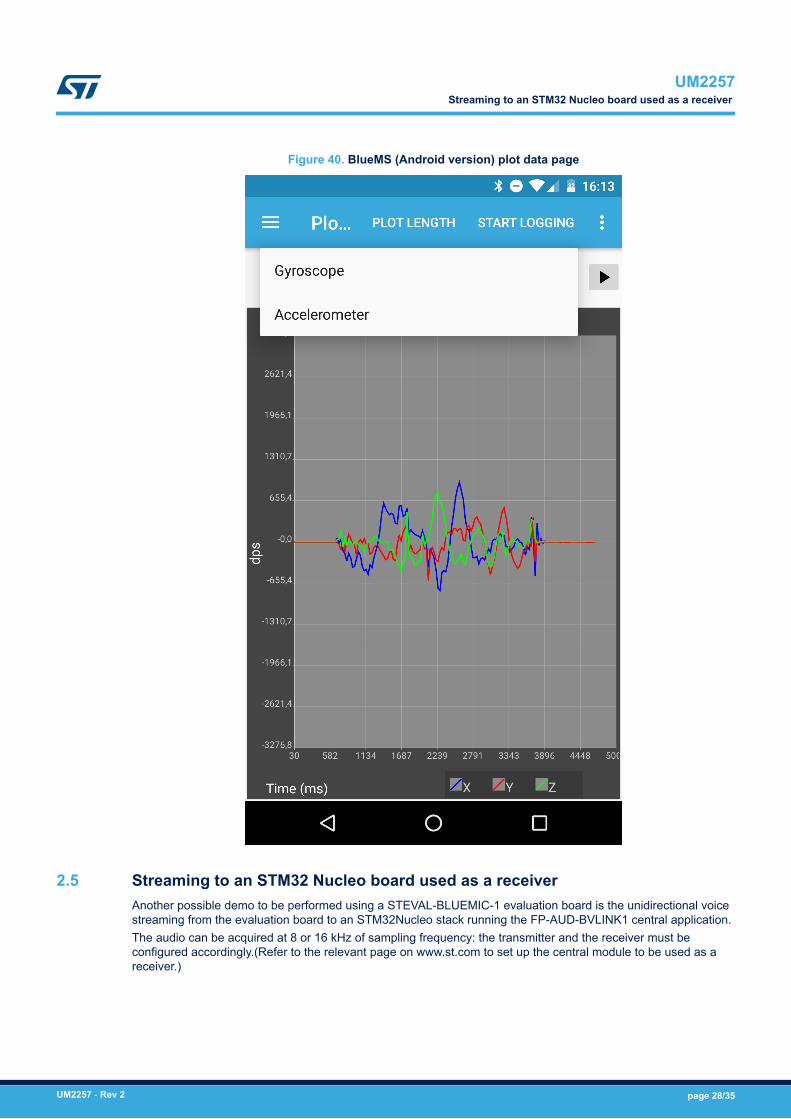
Figure 40. BlueMS (Android version) plot data page
2.5 Streaming to an STM32 Nucleo board used as a receiverAnother possible demo to be performed using a STEVAL-BLUEMIC-1 evaluation board is the unidirectional voicestreaming from the evaluation board to an STM32Nucleo stack running the FP-AUD-BVLINK1 central application.The audio can be acquired at 8 or 16 kHz of sampling frequency: the transmitter and the receiver must beconfigured accordingly.(Refer to the relevant page on www.st.com to set up the central module to be used as areceiver.)
UM2257Streaming to an STM32 Nucleo board used as a receiver
UM2257 - Rev 2 page 28/35
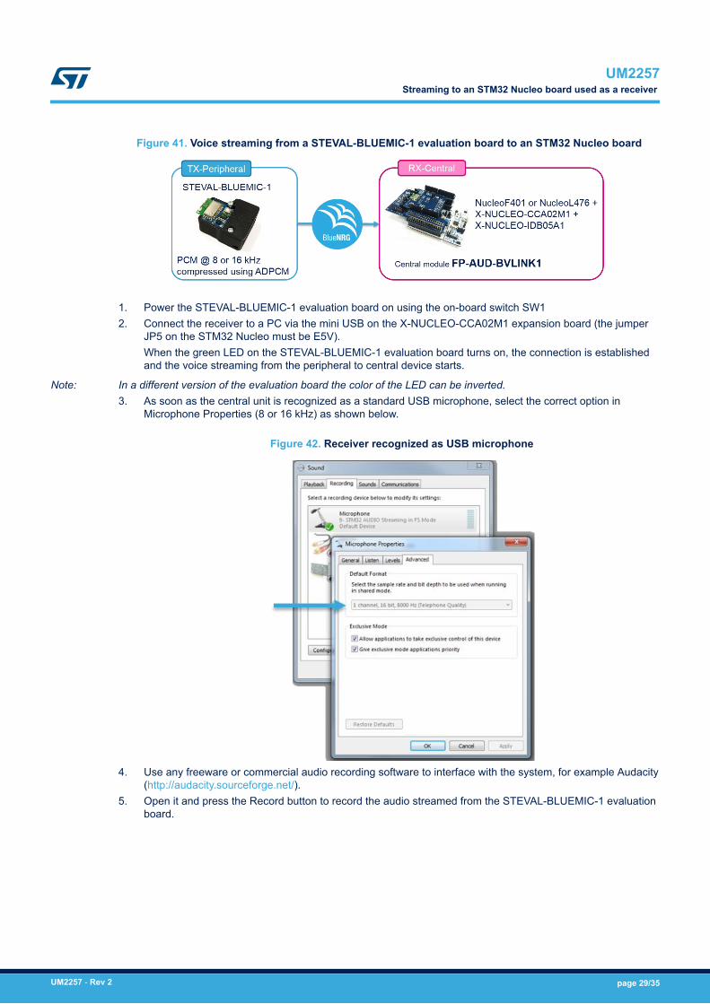
Figure 41. Voice streaming from a STEVAL-BLUEMIC-1 evaluation board to an STM32 Nucleo board
1. Power the STEVAL-BLUEMIC-1 evaluation board on using the on-board switch SW12. Connect the receiver to a PC via the mini USB on the X-NUCLEO-CCA02M1 expansion board (the jumper
JP5 on the STM32 Nucleo must be E5V).When the green LED on the STEVAL-BLUEMIC-1 evaluation board turns on, the connection is establishedand the voice streaming from the peripheral to central device starts.
Note: In a different version of the evaluation board the color of the LED can be inverted.3. As soon as the central unit is recognized as a standard USB microphone, select the correct option in
Microphone Properties (8 or 16 kHz) as shown below.
Figure 42. Receiver recognized as USB microphone
4. Use any freeware or commercial audio recording software to interface with the system, for example Audacity(http://audacity.sourceforge.net/).
5. Open it and press the Record button to record the audio streamed from the STEVAL-BLUEMIC-1 evaluationboard.
UM2257Streaming to an STM32 Nucleo board used as a receiver
UM2257 - Rev 2 page 29/35
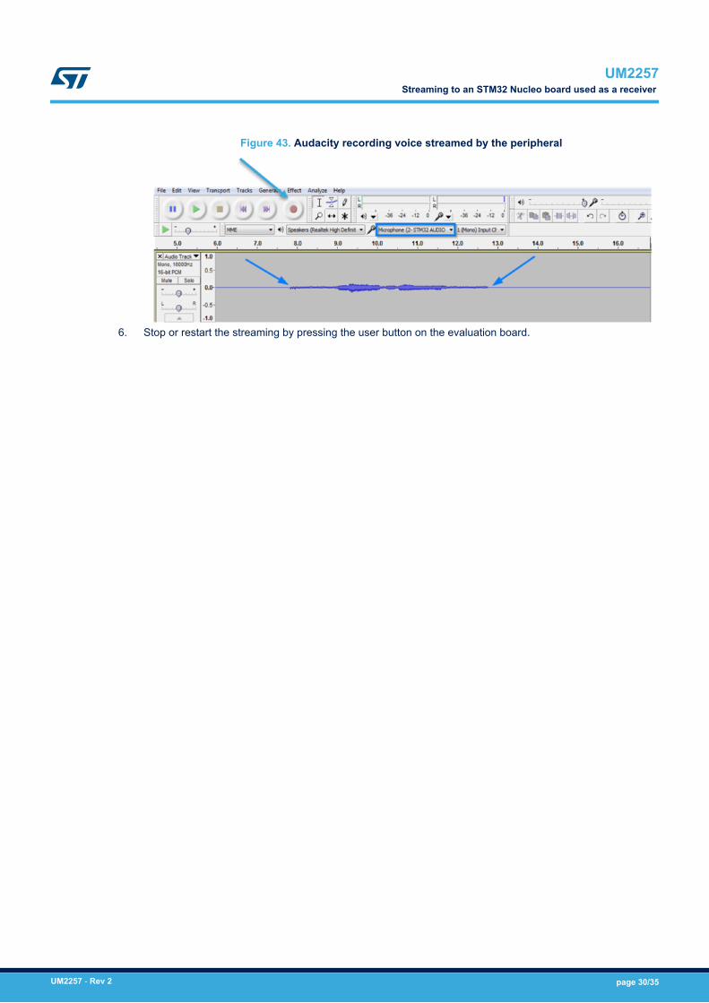
Figure 43. Audacity recording voice streamed by the peripheral
6. Stop or restart the streaming by pressing the user button on the evaluation board.
UM2257Streaming to an STM32 Nucleo board used as a receiver
UM2257 - Rev 2 page 30/35
Revision history
Table 3. Document revision history
Date Version Changes
17-Jul-2017 1 Initial release
08-Feb-2018 2 Added new product MP34TD05-A
UM2257
UM2257 - Rev 2 page 31/35
Contents
1 Getting started. . . . . . . . . . . . . . . . . . . . . . . . . . . . . . . . . . . . . . . . . . . . . . . . . . . . . . . . . . . . . . . . . . . . .2
1.1 Hardware description. . . . . . . . . . . . . . . . . . . . . . . . . . . . . . . . . . . . . . . . . . . . . . . . . . . . . . . . . . . 2
1.1.1 Features. . . . . . . . . . . . . . . . . . . . . . . . . . . . . . . . . . . . . . . . . . . . . . . . . . . . . . . . . . . . . . . 2
1.1.2 Evaluation kit . . . . . . . . . . . . . . . . . . . . . . . . . . . . . . . . . . . . . . . . . . . . . . . . . . . . . . . . . . . 2
1.1.3 Evaluation board . . . . . . . . . . . . . . . . . . . . . . . . . . . . . . . . . . . . . . . . . . . . . . . . . . . . . . . . 3
1.1.4 Schematic diagrams. . . . . . . . . . . . . . . . . . . . . . . . . . . . . . . . . . . . . . . . . . . . . . . . . . . . . . 4
1.2 Software description . . . . . . . . . . . . . . . . . . . . . . . . . . . . . . . . . . . . . . . . . . . . . . . . . . . . . . . . . . . 7
1.2.1 Overview . . . . . . . . . . . . . . . . . . . . . . . . . . . . . . . . . . . . . . . . . . . . . . . . . . . . . . . . . . . . . . 7
1.2.2 Architecture . . . . . . . . . . . . . . . . . . . . . . . . . . . . . . . . . . . . . . . . . . . . . . . . . . . . . . . . . . . . 7
1.2.3 Folder structure . . . . . . . . . . . . . . . . . . . . . . . . . . . . . . . . . . . . . . . . . . . . . . . . . . . . . . . . . 7
1.2.4 APIs . . . . . . . . . . . . . . . . . . . . . . . . . . . . . . . . . . . . . . . . . . . . . . . . . . . . . . . . . . . . . . . . . . 8
1.2.5 BlueMic1 application . . . . . . . . . . . . . . . . . . . . . . . . . . . . . . . . . . . . . . . . . . . . . . . . . . . . . 8
1.2.6 Audio processing . . . . . . . . . . . . . . . . . . . . . . . . . . . . . . . . . . . . . . . . . . . . . . . . . . . . . . . . 9
1.2.7 ADPCM compression . . . . . . . . . . . . . . . . . . . . . . . . . . . . . . . . . . . . . . . . . . . . . . . . . . . . 10
1.2.8 Packetization . . . . . . . . . . . . . . . . . . . . . . . . . . . . . . . . . . . . . . . . . . . . . . . . . . . . . . . . . . 11
1.2.9 STSW-BLUEMIC-1 application description. . . . . . . . . . . . . . . . . . . . . . . . . . . . . . . . . . . . 12
1.3 BlueVoiceADPCM_BNRG1 library software description . . . . . . . . . . . . . . . . . . . . . . . . . . . . . 13
1.3.1 Initialization and configuration . . . . . . . . . . . . . . . . . . . . . . . . . . . . . . . . . . . . . . . . . . . . . 13
1.3.2 Working mode setup . . . . . . . . . . . . . . . . . . . . . . . . . . . . . . . . . . . . . . . . . . . . . . . . . . . . 13
1.3.3 Audio signal injection . . . . . . . . . . . . . . . . . . . . . . . . . . . . . . . . . . . . . . . . . . . . . . . . . . . . 14
1.3.4 Compressed audio streaming. . . . . . . . . . . . . . . . . . . . . . . . . . . . . . . . . . . . . . . . . . . . . . 14
2 System setup . . . . . . . . . . . . . . . . . . . . . . . . . . . . . . . . . . . . . . . . . . . . . . . . . . . . . . . . . . . . . . . . . . . . .15
2.1 Power supply . . . . . . . . . . . . . . . . . . . . . . . . . . . . . . . . . . . . . . . . . . . . . . . . . . . . . . . . . . . . . . . . 15
2.2 STEVAL-BLUEMIC-1 evaluation board assembly in form factor case. . . . . . . . . . . . . . . . . . 15
2.3 STEVAL-BLUEMIC-1 evaluation board programming interface . . . . . . . . . . . . . . . . . . . . . . . 16
2.4 STEVAL-BLUEMIC-1 evaluation board demos . . . . . . . . . . . . . . . . . . . . . . . . . . . . . . . . . . . . 17
2.4.1 Streaming to a mobile device . . . . . . . . . . . . . . . . . . . . . . . . . . . . . . . . . . . . . . . . . . . . . . 17
2.5 Streaming to an STM32 Nucleo board used as a receiver . . . . . . . . . . . . . . . . . . . . . . . . . . . 28
Revision history . . . . . . . . . . . . . . . . . . . . . . . . . . . . . . . . . . . . . . . . . . . . . . . . . . . . . . . . . . . . . . . . . . . . . . .31
UM2257Contents
UM2257 - Rev 2 page 32/35
List of tablesTable 1. STEVAL-BLUEMIC-1 evaluation board main component details. . . . . . . . . . . . . . . . . . . . . . . . . . . . . . . . . . . . 4Table 2. BlueMic1 UUID summary table . . . . . . . . . . . . . . . . . . . . . . . . . . . . . . . . . . . . . . . . . . . . . . . . . . . . . . . . . . 9Table 3. Document revision history . . . . . . . . . . . . . . . . . . . . . . . . . . . . . . . . . . . . . . . . . . . . . . . . . . . . . . . . . . . . . 31
UM2257List of tables
UM2257 - Rev 2 page 33/35
List of figuresFigure 1. STEVAL-BLUEMIC-1 evaluation board . . . . . . . . . . . . . . . . . . . . . . . . . . . . . . . . . . . . . . . . . . . . . . . . . . . 1Figure 2. STEVAL-BLUEMIC-1 evaluation kit . . . . . . . . . . . . . . . . . . . . . . . . . . . . . . . . . . . . . . . . . . . . . . . . . . . . . . 2Figure 3. STEVAL-BLUEMIC-1 evaluation board: top and bottom . . . . . . . . . . . . . . . . . . . . . . . . . . . . . . . . . . . . . . . . 3Figure 4. Battery . . . . . . . . . . . . . . . . . . . . . . . . . . . . . . . . . . . . . . . . . . . . . . . . . . . . . . . . . . . . . . . . . . . . . . . . . 3Figure 5. Plastic case . . . . . . . . . . . . . . . . . . . . . . . . . . . . . . . . . . . . . . . . . . . . . . . . . . . . . . . . . . . . . . . . . . . . . . 3Figure 6. SWD cable. . . . . . . . . . . . . . . . . . . . . . . . . . . . . . . . . . . . . . . . . . . . . . . . . . . . . . . . . . . . . . . . . . . . . . . 3Figure 7. STEVAL-BLUEMIC-1 evaluation board hardware architecture. . . . . . . . . . . . . . . . . . . . . . . . . . . . . . . . . . . . 4Figure 8. STEVAL-BLUEMIC-1 evaluation board main components . . . . . . . . . . . . . . . . . . . . . . . . . . . . . . . . . . . . . . 4Figure 9. Power and SPBTLE-1S module . . . . . . . . . . . . . . . . . . . . . . . . . . . . . . . . . . . . . . . . . . . . . . . . . . . . . . . . 5Figure 10. MEMS, button and LEDs . . . . . . . . . . . . . . . . . . . . . . . . . . . . . . . . . . . . . . . . . . . . . . . . . . . . . . . . . . . . . 6Figure 11. STSW-BLUEMIC-1 software architecture . . . . . . . . . . . . . . . . . . . . . . . . . . . . . . . . . . . . . . . . . . . . . . . . . . 7Figure 12. STSW-BLUEMIC-1 folder structure . . . . . . . . . . . . . . . . . . . . . . . . . . . . . . . . . . . . . . . . . . . . . . . . . . . . . . 8Figure 13. STSW-BLUEMIC-1 audio processing chain . . . . . . . . . . . . . . . . . . . . . . . . . . . . . . . . . . . . . . . . . . . . . . . 10Figure 14. ADPCM encode-decode schema . . . . . . . . . . . . . . . . . . . . . . . . . . . . . . . . . . . . . . . . . . . . . . . . . . . . . . 10Figure 15. ADPCM packet mechanism . . . . . . . . . . . . . . . . . . . . . . . . . . . . . . . . . . . . . . . . . . . . . . . . . . . . . . . . . . 11Figure 16. BLE packets for 16 Hz audio . . . . . . . . . . . . . . . . . . . . . . . . . . . . . . . . . . . . . . . . . . . . . . . . . . . . . . . . . 12Figure 17. STSW-BLUEMIC-1 software package architecture . . . . . . . . . . . . . . . . . . . . . . . . . . . . . . . . . . . . . . . . . . 12Figure 18. Battery connection and power switch. . . . . . . . . . . . . . . . . . . . . . . . . . . . . . . . . . . . . . . . . . . . . . . . . . . . 15Figure 19. STEVAL-BLUEMIC-1 evaluation board in plastic case . . . . . . . . . . . . . . . . . . . . . . . . . . . . . . . . . . . . . . . . 16Figure 20. STM32 Nucleo board and STEVAL-BLUEMIC-1 SWD connections with a 5-pin flat cable. . . . . . . . . . . . . . . . 17Figure 21. Voice streaming from the STEVAL-BLUEMIC-1 evaluation board to an Android™ or iOS™ mobile device . . . . 18Figure 22. BlueMS (Android version) app device list . . . . . . . . . . . . . . . . . . . . . . . . . . . . . . . . . . . . . . . . . . . . . . . . . 18Figure 23. BlueMS (Android version) BlueVoice demo . . . . . . . . . . . . . . . . . . . . . . . . . . . . . . . . . . . . . . . . . . . . . . . 19Figure 24. BlueMS (Android version) ASR language selection . . . . . . . . . . . . . . . . . . . . . . . . . . . . . . . . . . . . . . . . . . 20Figure 25. BlueMS (Android version) Chinese ASR, iFlytek technology . . . . . . . . . . . . . . . . . . . . . . . . . . . . . . . . . . . . 21Figure 26. BlueMS (Android version) popup API key window . . . . . . . . . . . . . . . . . . . . . . . . . . . . . . . . . . . . . . . . . . . 21Figure 27. BlueMS (Android version) ASR service enabled . . . . . . . . . . . . . . . . . . . . . . . . . . . . . . . . . . . . . . . . . . . . 22Figure 28. BlueMS (Android version) voice recording . . . . . . . . . . . . . . . . . . . . . . . . . . . . . . . . . . . . . . . . . . . . . . . . 23Figure 29. BlueMS (Android version) recognised voice text . . . . . . . . . . . . . . . . . . . . . . . . . . . . . . . . . . . . . . . . . . . . 24Figure 30. Google Chromium-dev: search group . . . . . . . . . . . . . . . . . . . . . . . . . . . . . . . . . . . . . . . . . . . . . . . . . . . 25Figure 31. Google Chromium-dev: join group to post . . . . . . . . . . . . . . . . . . . . . . . . . . . . . . . . . . . . . . . . . . . . . . . . 25Figure 32. Google Chromium-dev: join the group . . . . . . . . . . . . . . . . . . . . . . . . . . . . . . . . . . . . . . . . . . . . . . . . . . . 25Figure 33. Google Chromium-dev: create project . . . . . . . . . . . . . . . . . . . . . . . . . . . . . . . . . . . . . . . . . . . . . . . . . . . 25Figure 34. Google Developers Console: new project. . . . . . . . . . . . . . . . . . . . . . . . . . . . . . . . . . . . . . . . . . . . . . . . . 26Figure 35. Google Developers Console: ASRProject. . . . . . . . . . . . . . . . . . . . . . . . . . . . . . . . . . . . . . . . . . . . . . . . . 26Figure 36. Google Developers Console: select API. . . . . . . . . . . . . . . . . . . . . . . . . . . . . . . . . . . . . . . . . . . . . . . . . . 26Figure 37. Google API Manager: enable API . . . . . . . . . . . . . . . . . . . . . . . . . . . . . . . . . . . . . . . . . . . . . . . . . . . . . . 26Figure 38. Google API Manager: create API key . . . . . . . . . . . . . . . . . . . . . . . . . . . . . . . . . . . . . . . . . . . . . . . . . . . 27Figure 39. Google API Manager: Android API key . . . . . . . . . . . . . . . . . . . . . . . . . . . . . . . . . . . . . . . . . . . . . . . . . . 27Figure 40. BlueMS (Android version) plot data page . . . . . . . . . . . . . . . . . . . . . . . . . . . . . . . . . . . . . . . . . . . . . . . . . 28Figure 41. Voice streaming from a STEVAL-BLUEMIC-1 evaluation board to an STM32 Nucleo board . . . . . . . . . . . . . . 29Figure 42. Receiver recognized as USB microphone . . . . . . . . . . . . . . . . . . . . . . . . . . . . . . . . . . . . . . . . . . . . . . . . 29Figure 43. Audacity recording voice streamed by the peripheral . . . . . . . . . . . . . . . . . . . . . . . . . . . . . . . . . . . . . . . . . 30
UM2257List of figures
UM2257 - Rev 2 page 34/35
IMPORTANT NOTICE – PLEASE READ CAREFULLY
STMicroelectronics NV and its subsidiaries (“ST”) reserve the right to make changes, corrections, enhancements, modifications, and improvements to STproducts and/or to this document at any time without notice. Purchasers should obtain the latest relevant information on ST products before placing orders. STproducts are sold pursuant to ST’s terms and conditions of sale in place at the time of order acknowledgement.
Purchasers are solely responsible for the choice, selection, and use of ST products and ST assumes no liability for application assistance or the design ofPurchasers’ products.
No license, express or implied, to any intellectual property right is granted by ST herein.
Resale of ST products with provisions different from the information set forth herein shall void any warranty granted by ST for such product.
ST and the ST logo are trademarks of ST. All other product or service names are the property of their respective owners.
Information in this document supersedes and replaces information previously supplied in any prior versions of this document.
© 2018 STMicroelectronics – All rights reserved
UM2257
UM2257 - Rev 2 page 35/35