Embed Size (px)
Citation preview
July 2017 DocID030868 Rev 1 1/55
www.st.com
UM2264 User manual
Getting started with the STEVAL-IDB007V1M SPBTLE-1S module
development kit
Introduction The SPBTLE-1S module is a low power Bluetooth® smart system-on-chip, compliant with the Bluetooth® v4.2 specification and supporting master, slave and simultaneous master-and-slave roles.
The available kit is the STEVAL-IDB007V1M development platform (order code: STEVAL-IDB007V1M).
The STEVAL-IDB007V1M provides a set of hardware resources for a wide range of application scenarios: sensor data (accelerometer, pressure and temperature sensor), remote control (buttons and LEDs) and debug message management through USB virtual COM. Three power options are available (USB only, battery only and external power supply plus USB) for high application development and testing flexibility.
Figure 1: STEVAL-IDB007V1M development platform
Contents UM2264
2/55 DocID030868 Rev 1
Contents
1 Getting started ................................................................................. 7
1.1 Kit contents ....................................................................................... 7
1.2 System requirements ........................................................................ 7
1.3 BlueNRG-1 development kit setup .................................................... 7
2 Hardware description ...................................................................... 8
2.1 STEVAL-IDB007V1M1 board overview ............................................. 8
2.2 SPBTLE-1S module connections ...................................................... 9
2.3 Power supply ................................................................................... 11
2.4 Jumpers .......................................................................................... 11
2.5 Sensors ........................................................................................... 11
2.6 Extension connector ........................................................................ 12
2.7 Push-buttons ................................................................................... 12
2.8 JTAG connector .............................................................................. 12
2.9 LEDs ............................................................................................... 12
2.10 STM32L151CBU6 microcontroller ................................................... 12
2.11 Current measurements ................................................................... 12
2.12 Hardware setup ............................................................................... 13
3 BlueNRG-1 Navigator .................................................................... 14
3.1 BlueNRG-1 Navigator ‘Demonstration Applications’ ....................... 14
3.1.1 BlueNRG-1 Navigator ‘Basic examples’ ........................................... 16
3.1.2 BlueNRG-1 Navigator ‘BLE demonstration and test applications’ ... 16
3.1.3 BlueNRG-1 Navigator ‘Peripherals driver examples’ ....................... 17
3.2 BlueNRG-1 Navigator ‘Development Kits’ ....................................... 18
3.2.1 BlueNRG-1 Navigator ‘Release Notes’ and ‘License’ ...................... 18
4 BlueNRG-1 Flasher utility ............................................................. 19
4.1 How to run ....................................................................................... 19
4.2 Main user interface window ............................................................. 20
4.2.1 Main menu items .............................................................................. 20
4.2.2 Image file selection ........................................................................... 21
4.2.3 ‘Image File’ tab ................................................................................. 21
4.2.4 ‘Device Memory’ tab ......................................................................... 21
4.2.5 Using BlueNRG-1 Flasher utility with other boards .......................... 22
5 Programming with BlueNRG-1 system-on-chip .......................... 24
UM2264 Contents
DocID030868 Rev 1 3/55
5.1 Software directory structure ............................................................ 24
6 BlueNRG-1 Beacon demonstration application .......................... 25
6.1 BLE Beacon application setup ........................................................ 25
6.1.1 Initialization ....................................................................................... 25
6.1.2 Define advertising data ..................................................................... 25
6.1.3 Entering non-connectable mode ...................................................... 25
7 BlueNRG-1 chat demo application ............................................... 27
7.1 Peripheral and central device setup ................................................ 27
7.1.1 Initialization ....................................................................................... 27
7.1.2 Add service and characteristics ........................................................ 28
7.1.3 Enter connectable mode................................................................... 28
7.1.4 Connection with central device ......................................................... 28
8 BLE chat master and slave demo application ............................. 30
8.1 BlueNRG-1 chat master and slave roles ......................................... 30
8.1.1 Initialization ....................................................................................... 30
8.1.2 Add service and characteristics ........................................................ 31
8.1.3 Start discovery procedure ................................................................ 31
8.1.4 Enter connectable mode................................................................... 31
8.1.5 Connection with chat master and slave client device ....................... 31
9 BlueNRG-1 remote control demo application.............................. 32
9.1 BLE remote control application setup .............................................. 32
9.1.1 Initialization ....................................................................................... 32
9.1.2 Define advertising data ..................................................................... 33
9.1.3 Add service and characteristics ........................................................ 33
9.1.4 Connection with a BLE Central device ............................................. 33
10 BlueNRG-1 sensor profile demo ................................................... 34
10.1 BlueNRG app for smartphones ....................................................... 35
10.2 BlueNRG-1 sensor profile demo: connection with a central device . 35
10.2.1 Initialization ....................................................................................... 35
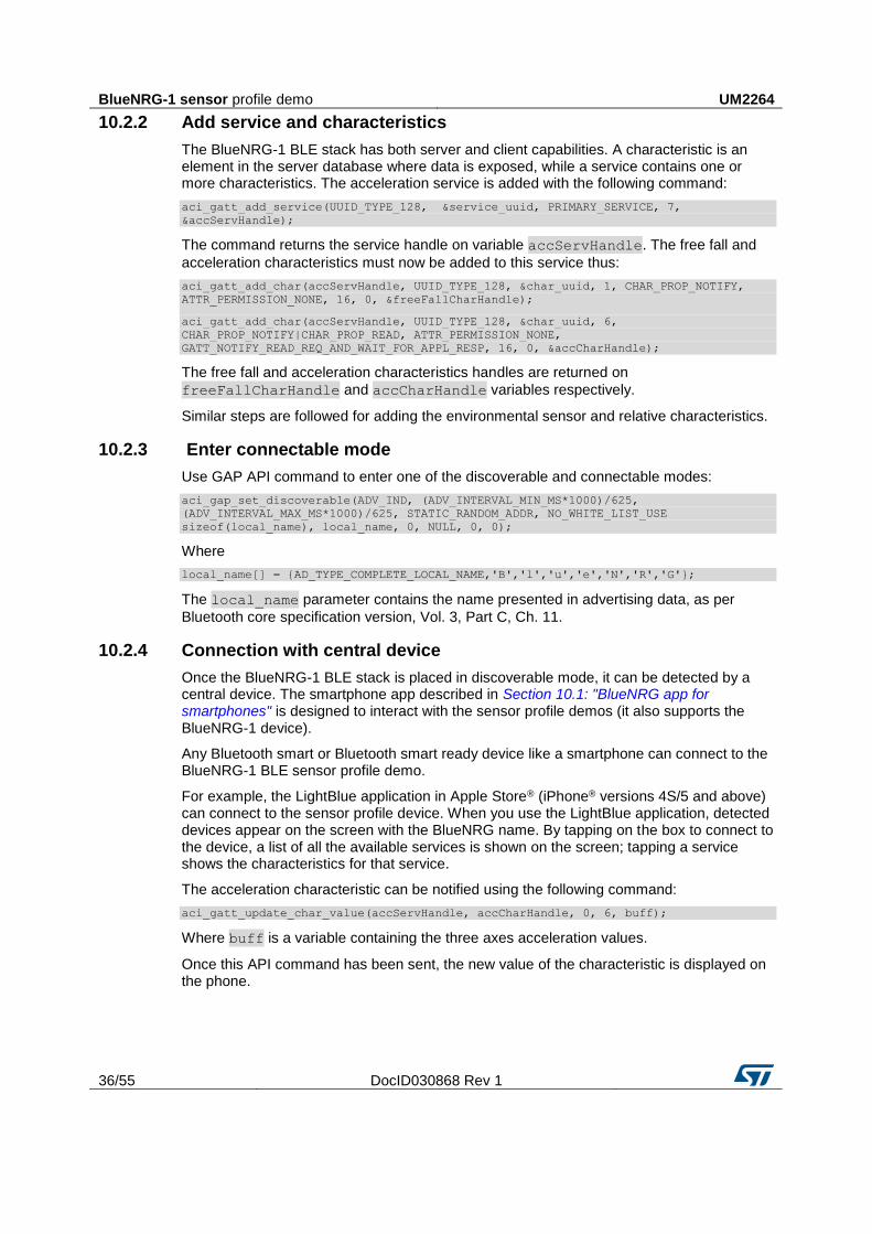
10.2.2 Add service and characteristics ........................................................ 36
10.2.3 Enter connectable mode................................................................... 36
10.2.4 Connection with central device ......................................................... 36
11 BlueNRG-1 sensor profile central demo ...................................... 37
12 BlueNRG-1 HID/HOGP demonstration application ...................... 38
12.1 BLE HID/HOGP mouse demonstration application ......................... 38
Contents UM2264
4/55 DocID030868 Rev 1
12.2 BLE HID/HOGP keyboard demonstration application ..................... 38
13 BlueNRG-1 throughput demonstration application .................... 39
13.1 BLE unidirectional throughput scenario ........................................... 39
13.2 BLE bidirectional throughput scenario ............................................. 39
14 BLE notification consumer demonstration application .............. 41
15 BlueNRG-1 peripheral driver examples ....................................... 42
15.1 ADC examples ................................................................................ 42
15.2 GPIO examples ............................................................................... 42
15.3 I²C examples ................................................................................... 43
15.4 Micro examples ............................................................................... 43
15.5 RTC examples ................................................................................ 44
15.6 SPI examples .................................................................................. 44
15.7 SysTick examples ........................................................................... 45
15.8 Timers examples ............................................................................. 45
15.9 UART examples .............................................................................. 47
15.10 WDG examples ............................................................................... 47
16 Schematic diagrams ...................................................................... 48
17 Revision history ............................................................................ 54
UM2264 List of tables
DocID030868 Rev 1 5/55
List of tables
Table 1: STEVAL-IDB007V1M board component descriptions .................................................................. 9 Table 2: SPBTLE-1S module pin description with board functions ............................................................ 9 Table 3: STEVAL-IDB007V1M kit platform power supply modes ............................................................ 11 Table 4: STEVAL-IDB007V1M kit platform jumpers ................................................................................. 11 Table 5: BlueNRG-1 Beacon advertising manufacturing data .................................................................. 25 Table 6: Serial port configuration .............................................................................................................. 27 Table 7: BLE remote advertising data ...................................................................................................... 32 Table 8: Document revision history .......................................................................................................... 54
List of figures UM2264
6/55 DocID030868 Rev 1
List of figures
Figure 1: STEVAL-IDB007V1M development platform .............................................................................. 1 Figure 2: STEVAL-IDB007V1M board components ................................................................................... 8 Figure 3: BlueNRG-1 Navigator ................................................................................................................ 14 Figure 4: BLE Beacon application ............................................................................................................ 15 Figure 5: BLE Beacon Flash programming............................................................................................... 15 Figure 6: BLE Beacon documentation ...................................................................................................... 16 Figure 7: Basic examples ......................................................................................................................... 16 Figure 8: BLE demonstration and test applications .................................................................................. 17 Figure 9: Peripherals driver examples ...................................................................................................... 17 Figure 10: STEVAL-IDB007V1M Kit components .................................................................................... 18 Figure 11: BlueNRG-1 Flasher utility ........................................................................................................ 19 Figure 12: BlueNRG-1 Flasher utility main window .................................................................................. 20 Figure 13: BlueNRG-1 Flasher utility file selection ................................................................................... 21 Figure 14: BlueNRG-1 Flasher utility image file viewer ............................................................................ 21 Figure 15: BlueNRG-1 Flasher utility device memory viewer ................................................................... 22 Figure 16: BlueNRG-1 Flasher utility changing memory fields ................................................................. 22 Figure 17: BlueNRG-1 Flasher utility ‘Comport Setting’ popup ................................................................ 23 Figure 18: BLE chat client ......................................................................................................................... 29 Figure 19: BLE chat server ....................................................................................................................... 29 Figure 20: BLE sensor demo GATT database ......................................................................................... 34 Figure 21: BlueNRG sensor app ............................................................................................................... 35 Figure 22: STEVAL-IDB007V1M Arduino connectors .............................................................................. 48 Figure 23: STEVAL-IDB007V1M JTAG .................................................................................................... 48 Figure 24: STEVAL-IDB007V1M SPBTLE-1S module (BlueNRG-1) ....................................................... 49 Figure 25: STEVAL-IDB007V1M power management and sensors ........................................................ 50 Figure 26: STEVAL-IDB007V1M buttons and LEDs ................................................................................ 51 Figure 27: STEVAL-IDB007V1M STM32 microprocessor ........................................................................ 52 Figure 28: STEVAL-IDB007V1M USB, level translator, JTAG for micro .................................................. 53 Figure 29: STEVAL-IDB007V1M EEPROM/SWITCH .............................................................................. 53
UM2264 Getting started
DocID030868 Rev 1 7/55
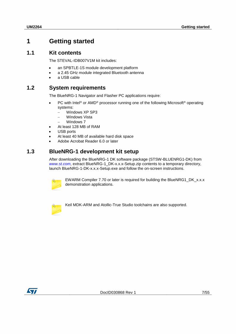
1 Getting started
1.1 Kit contents
The STEVAL-IDB007V1M kit includes:
an SPBTLE-1S module development platform
a 2.45 GHz module integrated Bluetooth antenna
a USB cable
1.2 System requirements
The BlueNRG-1 Navigator and Flasher PC applications require:
PC with Intel® or AMD® processor running one of the following Microsoft® operating systems:
Windows XP SP3
Windows Vista
Windows 7
At least 128 MB of RAM
USB ports
At least 40 MB of available hard disk space
Adobe Acrobat Reader 6.0 or later
1.3 BlueNRG-1 development kit setup
After downloading the BlueNRG-1 DK software package (STSW-BLUENRG1-DK) from www.st.com, extract BlueNRG-1_DK-x.x.x-Setup.zip contents to a temporary directory, launch BlueNRG-1-DK-x.x.x-Setup.exe and follow the on-screen instructions.
EWARM Compiler 7.70 or later is required for building the BlueNRG1_DK_x.x.x demonstration applications.
Keil MDK-ARM and Atollic-True Studio toolchains are also supported.
Hardware description UM2264
8/55 DocID030868 Rev 1
2 Hardware description
2.1 STEVAL-IDB007V1M1 board overview
The SPBTLE-1S module in the STEVAL-IDB007V1M development kit lets you experiment with BlueNRG-1 system-on-chip functions. It features:
Bluetooth® SMART board based on the BlueNRG-1 Bluetooth low energy system-on-chip
Associated BlueNRG-1 development kit software package including firmware and documentation
Up to +5 dBm available output radiated power (by the module integrated antenna)
Excellent receiver sensitivity (-88 dBm)
Very low power consumption: 7.7 mA RX and 8.3 mA TX at -2 dBm
Bluetooth® low energy compliant, supports master, slave and simultaneous master-and-slave roles
SMA connector for antenna or measuring equipment
3 user LEDs
2 user buttons
3D digital accelerometer and 3D digital gyroscope
MEMS pressure sensor with embedded temperature sensor
Battery holder
JTAG debug connector
USB to serial bridge for providing I/O channel with the BlueNRG-1 device
Jumper for measuring current for BlueNRG-1 only
RoHS compliant
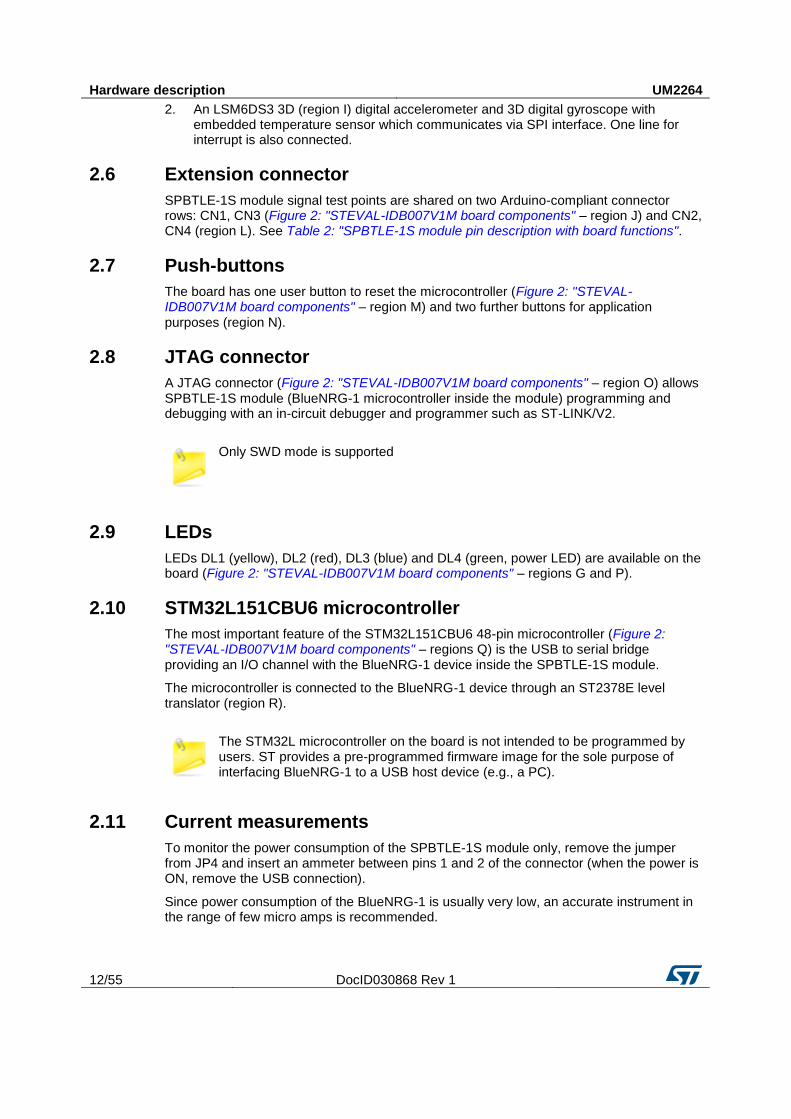
The following figure and table describe physical sections of the board.
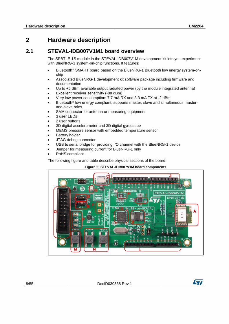
Figure 2: STEVAL-IDB007V1M board components
UM2264 Hardware description
DocID030868 Rev 1 9/55
Table 1: STEVAL-IDB007V1M board component descriptions
Region Description
A SPBTLE-1S module
C Micro USB connector for power supply and I/O
O JTAG connector
M RESET button
N two USER buttons
H LPS25HB MEMS pressure sensor with embedded temperature
I LSM6DS3 3D digital accelerometer and 3D digital gyroscope
G PWR LED
P three user LEDs
back of the PCB
battery holder for two AAA batteries
J, L Two rows of Arduino-compliant connectors
Q STM32L151CBU6 48-pin microcontroller (USB to serial bridge for I/O channel to PC communication)(1)
R ST2378E level translator to adapt voltage level between STM32 and SPBTLE-1S
Notes:
(1)STM32 is not intended to be programmed by users
2.2 SPBTLE-1S module connections
The SPBTLE-1S module, containing the very low power Bluetooth low energy (BLE) single-mode system-on-chip (Figure 2: "STEVAL-IDB007V1M board components" – region A) has 160 KB, 256 KB of Flash, 24 KB of RAM, a 32-bit core ARM® Cortex®-M0 processor and several peripherals (ADC, GPIOs, I²C, SPI, Timers, UART, WDG and RTC).
The microcontroller is connected to various components such as buttons, LEDs and sensors. The following table describes the microcontroller pin functions.
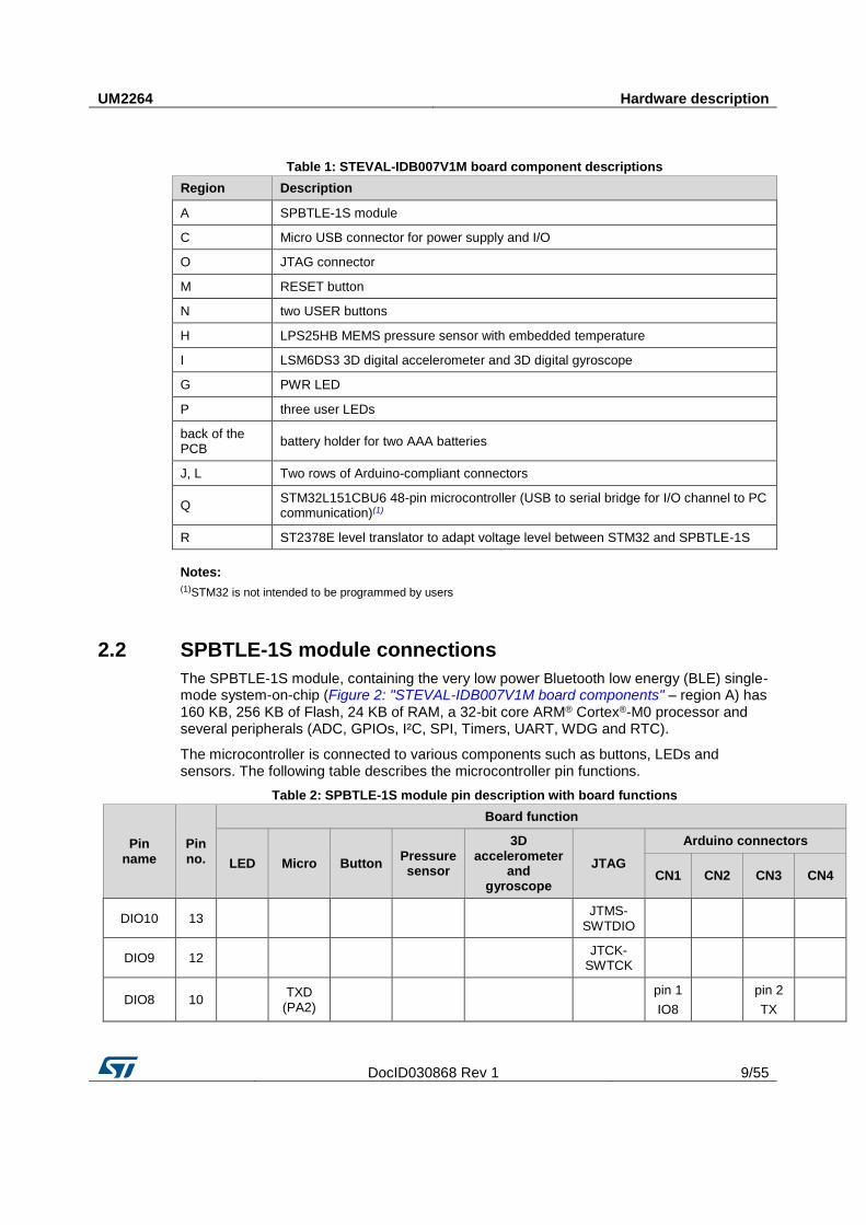
Table 2: SPBTLE-1S module pin description with board functions
Pin name
Pin no.
Board function
LED Micro Button Pressure sensor
3D accelerometer
and gyroscope
JTAG
Arduino connectors
CN1 CN2 CN3 CN4
DIO10 13
JTMS-SWTDIO
DIO9 12
JTCK-SWTCK
DIO8 10
TXD (PA2)
pin 1
IO8
pin 2
TX
Hardware description UM2264
10/55 DocID030868 Rev 1
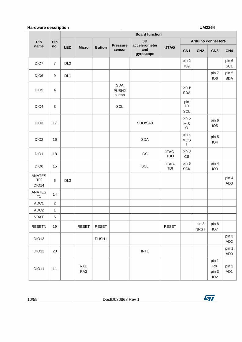
Pin name
Pin no.
Board function
LED Micro Button Pressure sensor
3D accelerometer
and gyroscope
JTAG
Arduino connectors
CN1 CN2 CN3 CN4
DIO7 7 DL2
pin 2
IO9
pin 6
SCL
DIO6 9 DL1
pin 7
IO6
pin 5
SDA
DIO5 4
SDA
PUSH2 button
pin 9
SDA
DIO4 3
SCL
pin 10
SCL
DIO3 17
SDO/SA0
pin 5
MISO
pin 6
IO5
DIO2 16
SDA
pin 4
MOSI
pin 5
IO4
DIO1 18
CS JTAG-TDO
pin 3
CS
DIO0 15
SCL JTAG-
TDI
pin 6
SCK
pin 4
IO3
ANATEST0/
DIO14
6 DL3
pin 4
AD3
ANATEST1
14
ADC1 2
ADC2 1
VBAT 5
RESETN 19
RESET RESET
RESET
pin 3
NRST
pin 8
IO7
DIO13
PUSH1
pin 3
AD2
DIO12 20
INT1
pin 1
AD0
DIO11 11
RXD
PA3
pin 1
RX
pin 3
IO2
pin 2
AD1
UM2264 Hardware description
DocID030868 Rev 1 11/55
The board section labeled SPBTLE-1 (Figure 2: "STEVAL-IDB007V1M board components" – region A) includes only the certified and BQE qualified module SPBTLE-1S (for more details, see Figure 24: "STEVAL-IDB007V1M SPBTLE-1S module (BlueNRG-1)").
2.3 Power supply
Green LED DL4 (Figure 2: "STEVAL-IDB007V1M board components" – region G) signals the board is being powered, either via:
micro USB connector CN5 (Figure 2: "STEVAL-IDB007V1M board components" – region C)
two AAA batteries (region F)
an external DC power supply plus micro USB connector
The following table describes the power supply modes available on the STEVAL-IDB007V1M board and corresponding jumper settings.
Table 3: STEVAL-IDB007V1M kit platform power supply modes
Power supply mode
JP1 JP2 Comment
1 - USB Fitted: 1-2
Fitted: 2-3
USB supply through connector CN5 (Figure 2: "STEVAL-IDB007V1M board components" – region C)
2 - Battery Fitted: 2-3
Fitted: 1-2
The supply voltage must be provided through battery pins (region F).
3 - Combo Fitted: 1-2
Optional USB supply through connector CN5 for STM32L1; JP2 pin 2 external power for SPBTLE-1S
2.4 Jumpers
The following jumpers are available:
Table 4: STEVAL-IDB007V1M kit platform jumpers
Jumper Description
JP1 1-2: to provide power from USB (JP2: 2-3)
Open-3: to provide power from battery holder (JP2: 1-2)
JP2
1-2: to provide power from battery holder (JP1: 2-3)
2-3: to provide power from USB (JP1: 1-2)
JP2 pin 2 to VDD to provide external power supply to SPBTLE-1S (JP1: 1-2)
JP3 pin 1 and 2 UART RX and TX of MCU
pin 3 GND
JP4 Fitted: to provide VBLUE to SPBTLE-1S. It can be used also for current measurement.
2.5 Sensors
The following sensors are available on the platform:
1. An LPS25HB (Figure 2: "STEVAL-IDB007V1M board components" – region H) is a piezoresistive absolute pressure sensor which functions as a digital output barometer. The device comprises a sensing element and an IC interface which communicates through I²C from the sensing element to the application.
Hardware description UM2264
12/55 DocID030868 Rev 1
2. An LSM6DS3 3D (region I) digital accelerometer and 3D digital gyroscope with embedded temperature sensor which communicates via SPI interface. One line for interrupt is also connected.
2.6 Extension connector
SPBTLE-1S module signal test points are shared on two Arduino-compliant connector rows: CN1, CN3 (Figure 2: "STEVAL-IDB007V1M board components" – region J) and CN2, CN4 (region L). See Table 2: "SPBTLE-1S module pin description with board functions".
2.7 Push-buttons
The board has one user button to reset the microcontroller (Figure 2: "STEVAL-IDB007V1M board components" – region M) and two further buttons for application purposes (region N).
2.8 JTAG connector
A JTAG connector (Figure 2: "STEVAL-IDB007V1M board components" – region O) allows SPBTLE-1S module (BlueNRG-1 microcontroller inside the module) programming and debugging with an in-circuit debugger and programmer such as ST-LINK/V2.
Only SWD mode is supported
2.9 LEDs
LEDs DL1 (yellow), DL2 (red), DL3 (blue) and DL4 (green, power LED) are available on the board (Figure 2: "STEVAL-IDB007V1M board components" – regions G and P).
2.10 STM32L151CBU6 microcontroller
The most important feature of the STM32L151CBU6 48-pin microcontroller (Figure 2: "STEVAL-IDB007V1M board components" – regions Q) is the USB to serial bridge providing an I/O channel with the BlueNRG-1 device inside the SPBTLE-1S module.
The microcontroller is connected to the BlueNRG-1 device through an ST2378E level translator (region R).
The STM32L microcontroller on the board is not intended to be programmed by users. ST provides a pre-programmed firmware image for the sole purpose of interfacing BlueNRG-1 to a USB host device (e.g., a PC).
2.11 Current measurements
To monitor the power consumption of the SPBTLE-1S module only, remove the jumper from JP4 and insert an ammeter between pins 1 and 2 of the connector (when the power is ON, remove the USB connection).
Since power consumption of the BlueNRG-1 is usually very low, an accurate instrument in the range of few micro amps is recommended.
UM2264 Hardware description
DocID030868 Rev 1 13/55
2.12 Hardware setup
1 Configure the board to USB power supply mode as per the jumper settings in Table 3: "STEVAL-IDB007V1M kit platform power supply modes"
2 Connect the board to a PC via USB cable (connector CN5)
3 Verify the power indication LED DL4 is on
BlueNRG-1 Navigator UM2264
14/55 DocID030868 Rev 1
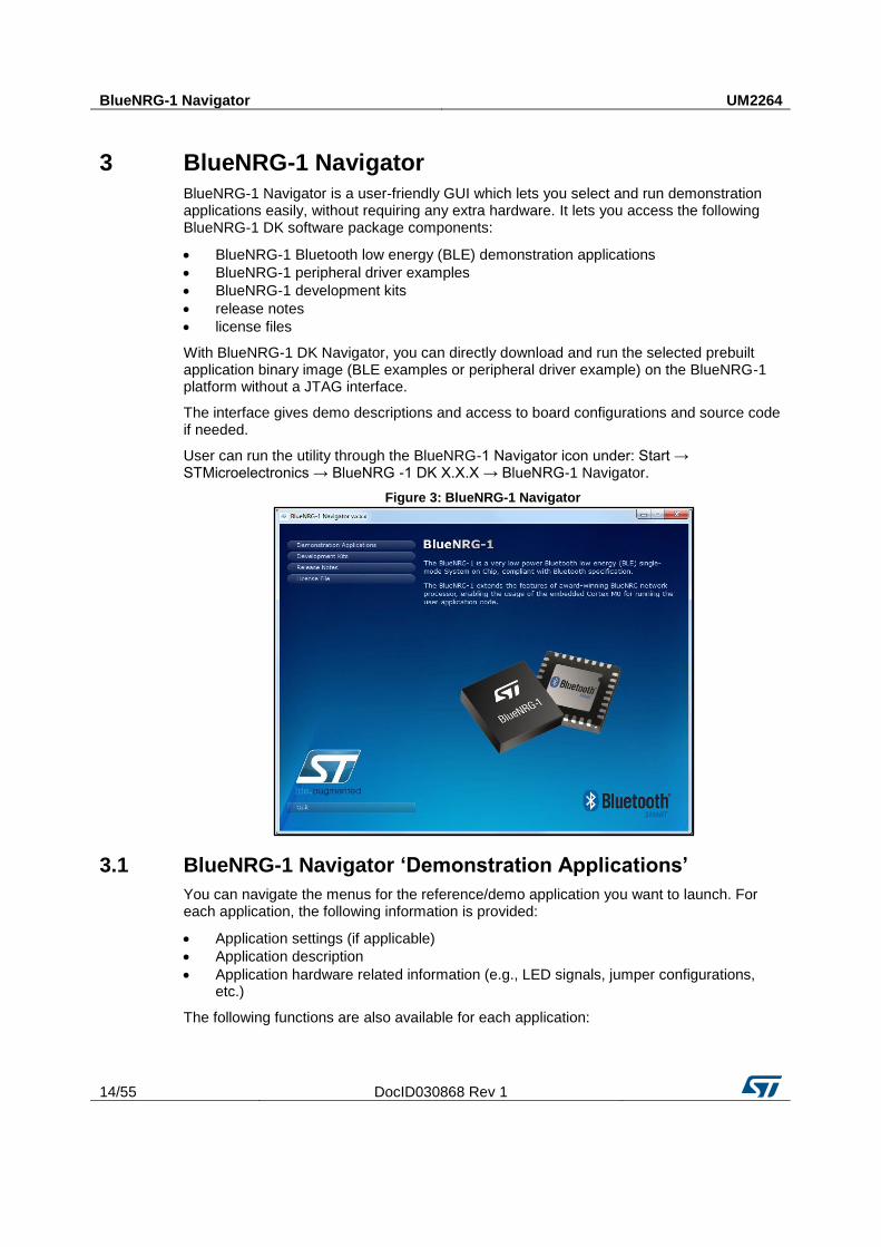
3 BlueNRG-1 Navigator
BlueNRG-1 Navigator is a user-friendly GUI which lets you select and run demonstration applications easily, without requiring any extra hardware. It lets you access the following BlueNRG-1 DK software package components:
BlueNRG-1 Bluetooth low energy (BLE) demonstration applications
BlueNRG-1 peripheral driver examples
BlueNRG-1 development kits
release notes
license files
With BlueNRG-1 DK Navigator, you can directly download and run the selected prebuilt application binary image (BLE examples or peripheral driver example) on the BlueNRG-1 platform without a JTAG interface.
The interface gives demo descriptions and access to board configurations and source code if needed.
User can run the utility through the BlueNRG-1 Navigator icon under: Start → STMicroelectronics → BlueNRG -1 DK X.X.X → BlueNRG-1 Navigator.
Figure 3: BlueNRG-1 Navigator
3.1 BlueNRG-1 Navigator ‘Demonstration Applications’
You can navigate the menus for the reference/demo application you want to launch. For each application, the following information is provided:
Application settings (if applicable)
Application description
Application hardware related information (e.g., LED signals, jumper configurations, etc.)
The following functions are also available for each application:
UM2264 BlueNRG-1 Navigator
DocID030868 Rev 1 15/55
Flash: to automatically download and run the available prebuilt binary file to a BlueNRG-1 or SPBTLE-1S platform connected to a PC USB port.
Doc: to display application documentation (html format)
Project: to open the project folder with application headers, source and project files.
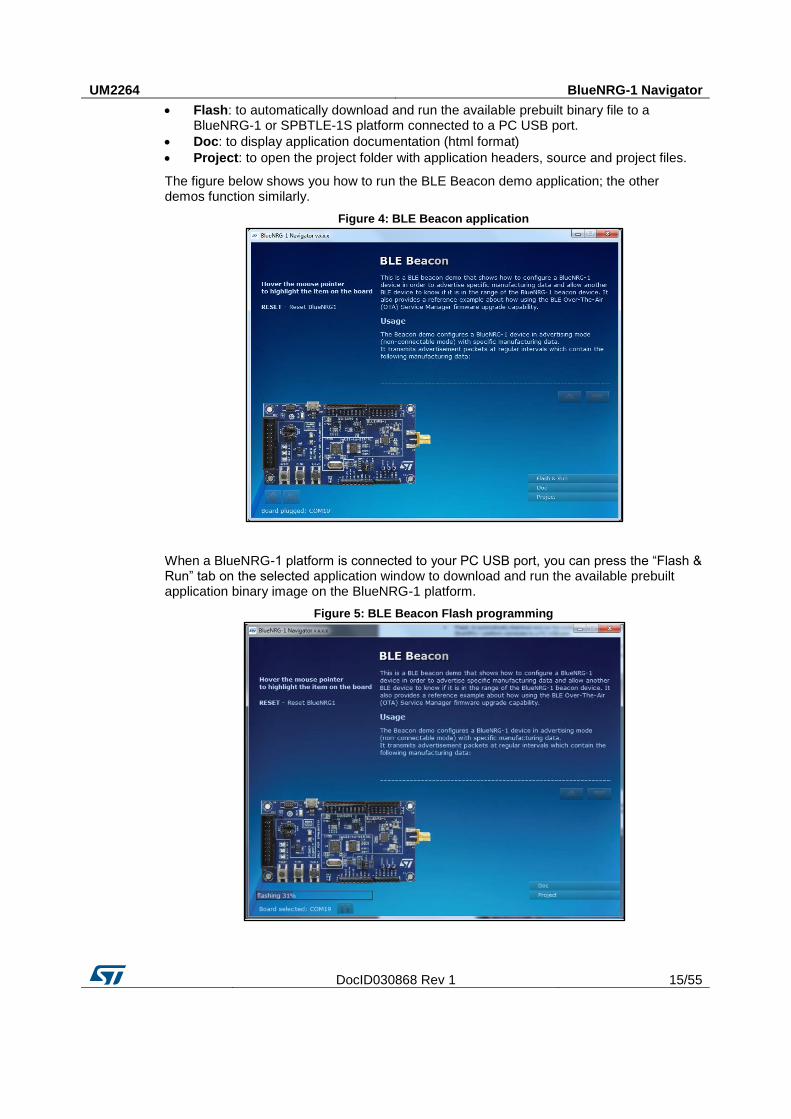
The figure below shows you how to run the BLE Beacon demo application; the other demos function similarly.
Figure 4: BLE Beacon application
When a BlueNRG-1 platform is connected to your PC USB port, you can press the “Flash & Run” tab on the selected application window to download and run the available prebuilt application binary image on the BlueNRG-1 platform.
Figure 5: BLE Beacon Flash programming
BlueNRG-1 Navigator UM2264
16/55 DocID030868 Rev 1
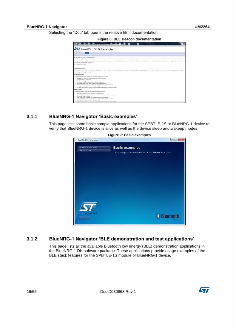
Selecting the “Doc” tab opens the relative html documentation.
Figure 6: BLE Beacon documentation
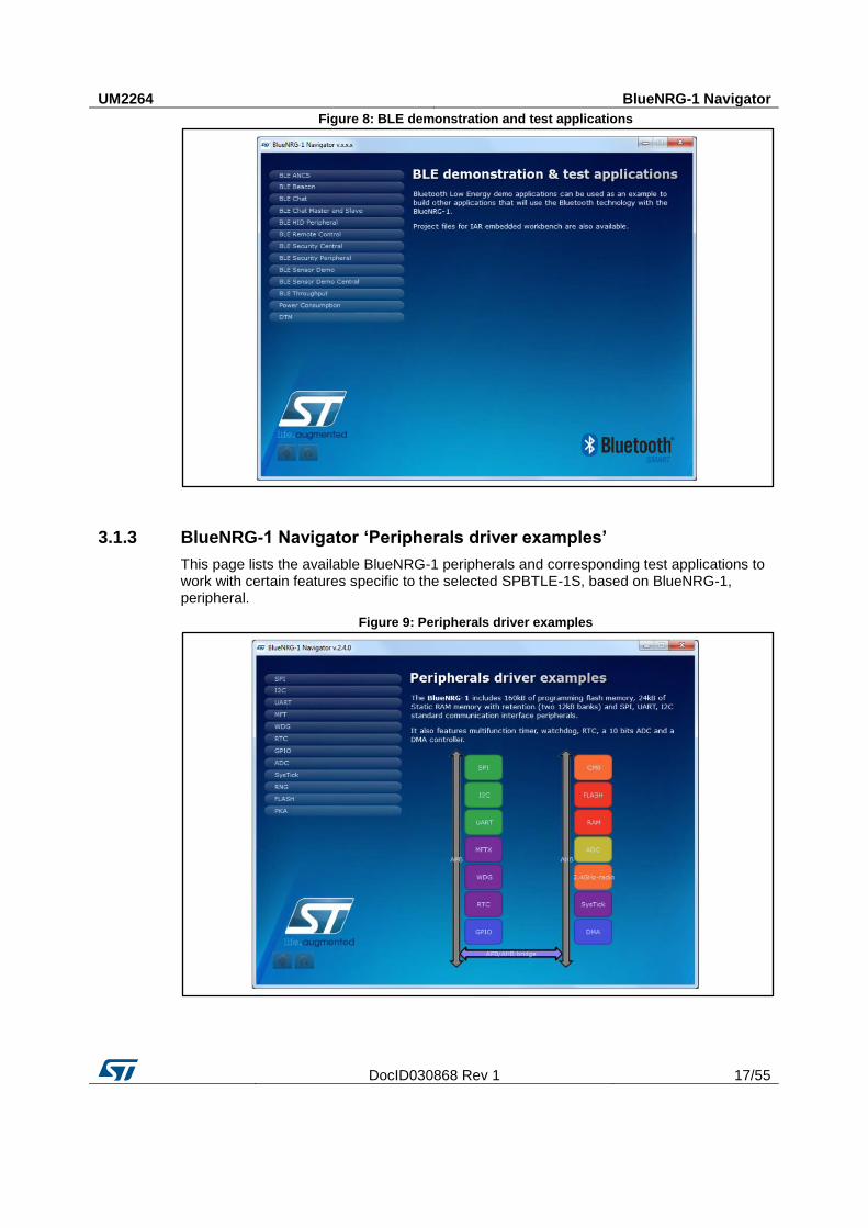
3.1.1 BlueNRG-1 Navigator ‘Basic examples’
This page lists some basic sample applications for the SPBTLE-1S or BlueNRG-1 device to verify that BlueNRG-1 device is alive as well as the device sleep and wakeup modes.
Figure 7: Basic examples
3.1.2 BlueNRG-1 Navigator ‘BLE demonstration and test applications’
This page lists all the available Bluetooth low energy (BLE) demonstration applications in the BlueNRG-1 DK software package. These applications provide usage examples of the BLE stack features for the SPBTLE-1S module or BlueNRG-1 device.
UM2264 BlueNRG-1 Navigator
DocID030868 Rev 1 17/55
Figure 8: BLE demonstration and test applications
3.1.3 BlueNRG-1 Navigator ‘Peripherals driver examples’
This page lists the available BlueNRG-1 peripherals and corresponding test applications to work with certain features specific to the selected SPBTLE-1S, based on BlueNRG-1, peripheral.
Figure 9: Peripherals driver examples
BlueNRG-1 Navigator UM2264
18/55 DocID030868 Rev 1
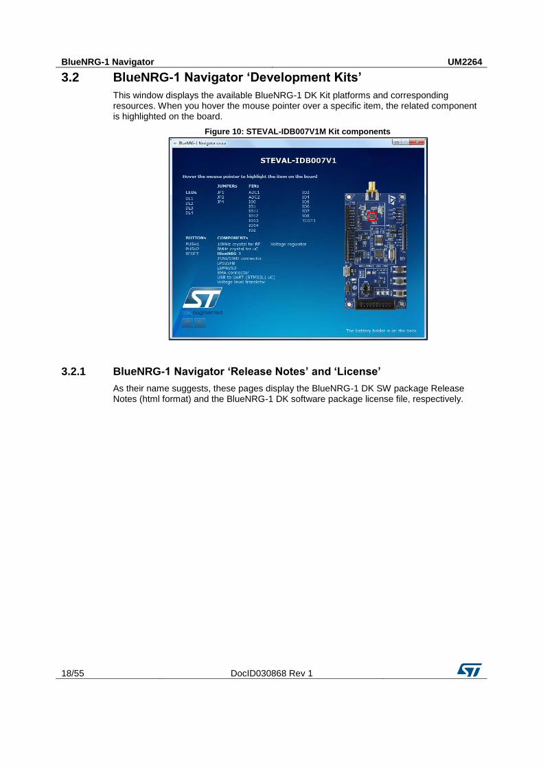
3.2 BlueNRG-1 Navigator ‘Development Kits’
This window displays the available BlueNRG-1 DK Kit platforms and corresponding resources. When you hover the mouse pointer over a specific item, the related component is highlighted on the board.
Figure 10: STEVAL-IDB007V1M Kit components
3.2.1 BlueNRG-1 Navigator ‘Release Notes’ and ‘License’
As their name suggests, these pages display the BlueNRG-1 DK SW package Release Notes (html format) and the BlueNRG-1 DK software package license file, respectively.
UM2264 BlueNRG-1 Flasher utility
DocID030868 Rev 1 19/55
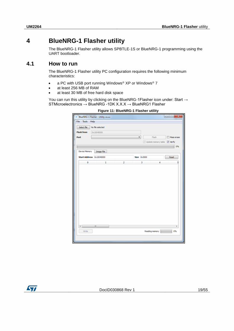
4 BlueNRG-1 Flasher utility
The BlueNRG-1 Flasher utility allows SPBTLE-1S or BlueNRG-1 programming using the UART bootloader.
4.1 How to run
The BlueNRG-1 Flasher utility PC configuration requires the following minimum characteristics:
a PC with USB port running Windows® XP or Windows® 7
at least 256 MB of RAM
at least 30 MB of free hard disk space
You can run this utility by clicking on the BlueNRG-1Flasher icon under: Start → STMicroelectronics → BlueNRG -1DK X.X.X → BlueNRG1 Flasher
Figure 11: BlueNRG-1 Flasher utility
BlueNRG-1 Flasher utility UM2264
20/55 DocID030868 Rev 1
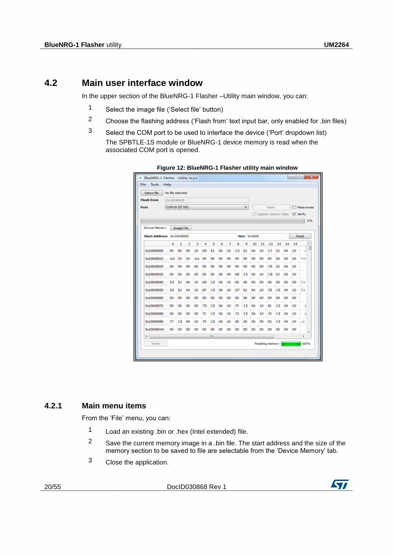
4.2 Main user interface window
In the upper section of the BlueNRG-1 Flasher –Utility main window, you can:
1 Select the image file (‘Select file’ button)
2 Choose the flashing address (‘Flash from’ text input bar, only enabled for .bin files)
3 Select the COM port to be used to interface the device (‘Port’ dropdown list)
The SPBTLE-1S module or BlueNRG-1 device memory is read when the associated COM port is opened.
Figure 12: BlueNRG-1 Flasher utility main window
4.2.1 Main menu items
From the ‘File’ menu, you can:
1 Load an existing .bin or .hex (Intel extended) file.
2 Save the current memory image in a .bin file. The start address and the size of the memory section to be saved to file are selectable from the ‘Device Memory’ tab.
3 Close the application.
UM2264 BlueNRG-1 Flasher utility
DocID030868 Rev 1 21/55
From the ‘Tools’ menu, you can mass erase all the device Flash memory.
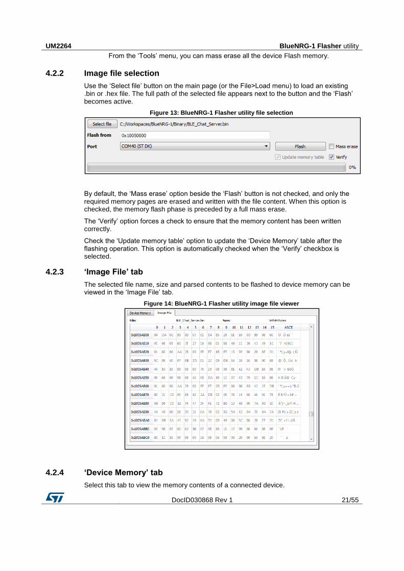
4.2.2 Image file selection
Use the ‘Select file’ button on the main page (or the File>Load menu) to load an existing .bin or .hex file. The full path of the selected file appears next to the button and the ‘Flash’ becomes active.
Figure 13: BlueNRG-1 Flasher utility file selection
By default, the ‘Mass erase’ option beside the ‘Flash’ button is not checked, and only the required memory pages are erased and written with the file content. When this option is checked, the memory flash phase is preceded by a full mass erase.
The ‘Verify’ option forces a check to ensure that the memory content has been written correctly.
Check the ‘Update memory table’ option to update the ‘Device Memory’ table after the flashing operation. This option is automatically checked when the ‘Verify’ checkbox is selected.
4.2.3 ‘Image File’ tab
The selected file name, size and parsed contents to be flashed to device memory can be viewed in the ‘Image File’ tab.
Figure 14: BlueNRG-1 Flasher utility image file viewer
4.2.4 ‘Device Memory’ tab
Select this tab to view the memory contents of a connected device.
BlueNRG-1 Flasher utility UM2264
22/55 DocID030868 Rev 1
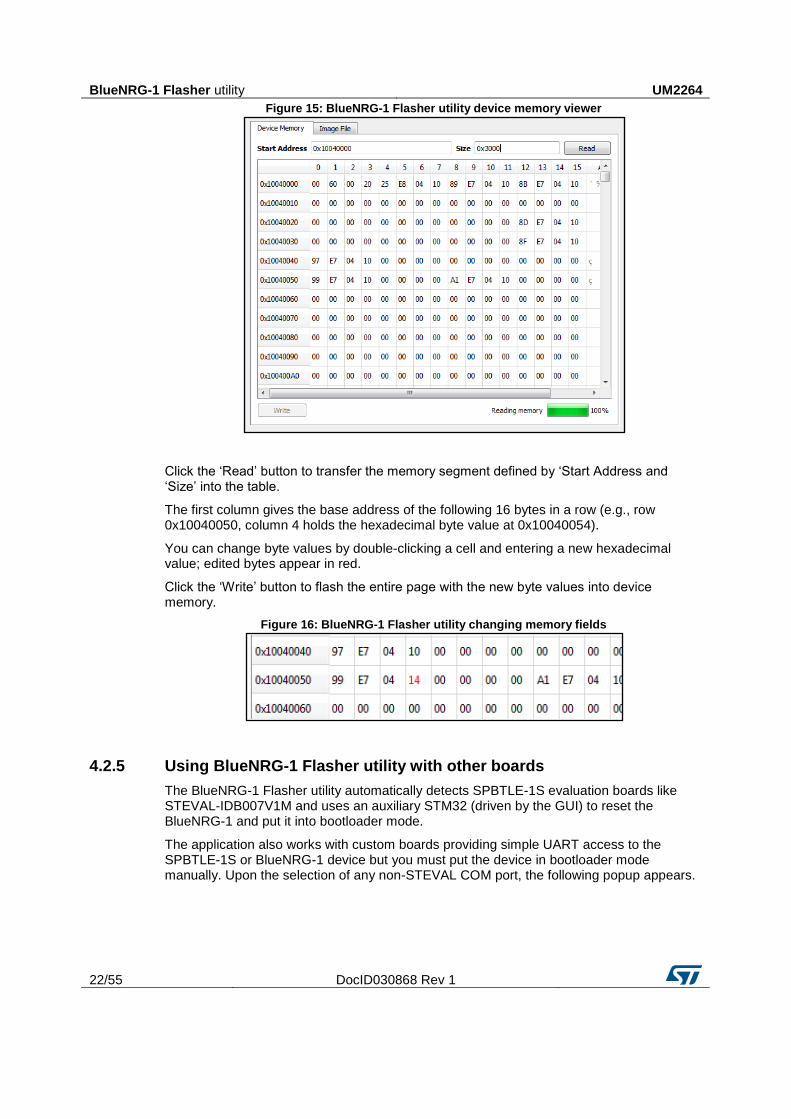
Figure 15: BlueNRG-1 Flasher utility device memory viewer
Click the ‘Read’ button to transfer the memory segment defined by ‘Start Address and ‘Size’ into the table.
The first column gives the base address of the following 16 bytes in a row (e.g., row 0x10040050, column 4 holds the hexadecimal byte value at 0x10040054).
You can change byte values by double-clicking a cell and entering a new hexadecimal value; edited bytes appear in red.
Click the ‘Write’ button to flash the entire page with the new byte values into device memory.
Figure 16: BlueNRG-1 Flasher utility changing memory fields
4.2.5 Using BlueNRG-1 Flasher utility with other boards
The BlueNRG-1 Flasher utility automatically detects SPBTLE-1S evaluation boards like STEVAL-IDB007V1M and uses an auxiliary STM32 (driven by the GUI) to reset the BlueNRG-1 and put it into bootloader mode.
The application also works with custom boards providing simple UART access to the SPBTLE-1S or BlueNRG-1 device but you must put the device in bootloader mode manually. Upon the selection of any non-STEVAL COM port, the following popup appears.
UM2264 BlueNRG-1 Flasher utility
DocID030868 Rev 1 23/55
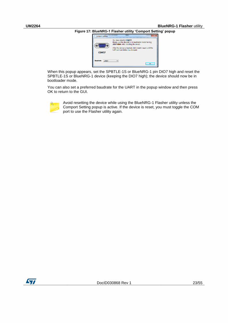
Figure 17: BlueNRG-1 Flasher utility ‘Comport Setting’ popup
When this popup appears, set the SPBTLE-1S or BlueNRG-1 pin DIO7 high and reset the SPBTLE-1S or BlueNRG-1 device (keeping the DIO7 high); the device should now be in bootloader mode.
You can also set a preferred baudrate for the UART in the popup window and then press OK to return to the GUI.
Avoid resetting the device while using the BlueNRG-1 Flasher utility unless the Comport Setting popup is active. If the device is reset, you must toggle the COM port to use the Flasher utility again.
Programming with BlueNRG-1 system-on-chip UM2264
24/55 DocID030868 Rev 1
5 Programming with BlueNRG-1 system-on-chip
The SPBTLE-1S module, based on BlueNRG-1 Bluetooth low energy (BLE) stack is provided as a binary library. A set of APIs to control BLE functionality. Some callbacks are also provided for user applications to handle BLE stack events. The user is simply requested to link this binary library to his or her application and use the relevant APIs to access BLE functions and complete the stack event callbacks to manage responses according to application requirements.
A set of software driver APIs is also included for accessing the BlueNRG-1 SoC peripherals and resources (ADC, GPIO, I²C, MFTX, Micro, RTC, SPI, SysTick, UART and WDG).
The development kit software includes sample code demonstrating how to configure BlueNRG-1 and use the device peripherals and BLE APIs and event callbacks. Documentation on the BLE APIs, callbacks, and peripheral drivers are provided in separate documents.
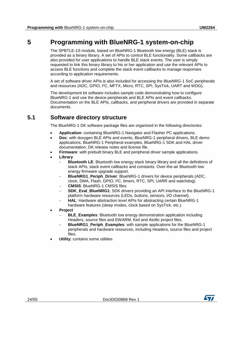
5.1 Software directory structure
The BlueNRG-1 DK software package files are organized in the following directories:
Application: containing BlueNRG-1 Navigator and Flasher PC applications.
Doc: with doxygen BLE APIs and events, BlueNRG-1 peripheral drivers, BLE demo applications, BlueNRG-1 Peripheral examples, BlueNRG-1 SDK and HAL driver documentation, DK release notes and license file.
Firmware: with prebuilt binary BLE and peripheral driver sample applications.
Library
Bluetooth LE: Bluetooth low energy stack binary library and all the definitions of stack APIs, stack event callbacks and constants. Over-the-air Bluetooth low energy firmware upgrade support.
BlueNRG1_Periph_Driver: BlueNRG-1 drivers for device peripherals (ADC, clock, DMA, Flash, GPIO, I²C, timers, RTC, SPI, UARR and watchdog).
CMSIS: BlueNRG-1 CMSIS files.
SDK_Eval_BlueNRG1: SDK drivers providing an API interface to the BlueNRG-1 platform hardware resources (LEDs, buttons, sensors, I/O channel).
HAL: Hardware abstraction level APIs for abstracting certain BlueNRG-1 hardware features (sleep modes, clock based on SysTick, etc.).
Project
BLE_Examples: Bluetooth low energy demonstration application including Headers, source files and EWARM, Keil and Atollic project files.
BlueNRG1_Periph_Examples: with sample applications for the BlueNRG-1 peripherals and hardware resources, including Headers, source files and project files.
Utility: contains some utilities
UM2264 BlueNRG-1 Beacon demonstration application
DocID030868 Rev 1 25/55
6 BlueNRG-1 Beacon demonstration application
The BlueNRG-1 Beacon demo is supported by the SPBTLE-1S or BlueNRG-1 development platform (STEVAL-IDB007V1 or STEVAL-IDB007V1M). It demonstrates how to configure a SPBTLE-1S or BlueNRG-1 device to advertise specific manufacturing data and allow another BLE device to determine whether it is in BlueNRG-1 BLE Beacon device range.
6.1 BLE Beacon application setup
This section describes how to configure a BlueNRG-1 device to act as a Beacon device.
6.1.1 Initialization
The BlueNRG-1 BLE stack must be correctly initialized thus:
aci_gatt_init();
aci_gap_init(GAP_PERIPHERAL_ROLE, 0, 0x08, &service_handle, &dev_name_char_handle,
&appearance_char_handle);
See the BlueNRG-1 BLE stack documentation for more information on these and following commands.
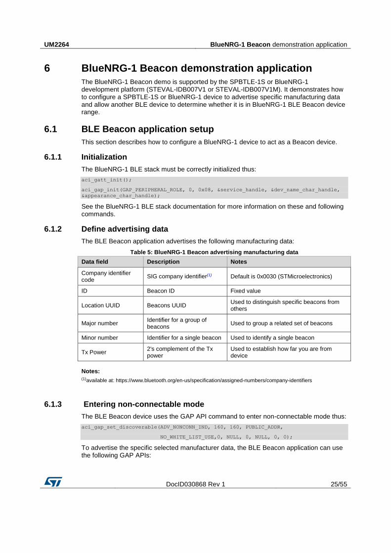
6.1.2 Define advertising data
The BLE Beacon application advertises the following manufacturing data:
Table 5: BlueNRG-1 Beacon advertising manufacturing data
Data field Description Notes
Company identifier code
SIG company identifier(1) Default is 0x0030 (STMicroelectronics)
ID Beacon ID Fixed value
Location UUID Beacons UUID Used to distinguish specific beacons from others
Major number Identifier for a group of beacons
Used to group a related set of beacons
Minor number Identifier for a single beacon Used to identify a single beacon
Tx Power 2's complement of the Tx power
Used to establish how far you are from device
Notes:
(1)available at: https://www.bluetooth.org/en-us/specification/assigned-numbers/company-identifiers
6.1.3 Entering non-connectable mode
The BLE Beacon device uses the GAP API command to enter non-connectable mode thus:
aci_gap_set_discoverable(ADV_NONCONN_IND, 160, 160, PUBLIC_ADDR,
NO_WHITE_LIST_USE,0, NULL, 0, NULL, 0, 0);
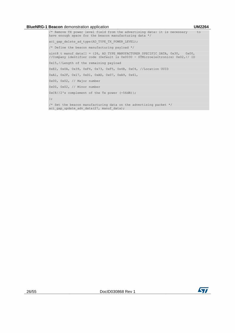
To advertise the specific selected manufacturer data, the BLE Beacon application can use the following GAP APIs:
BlueNRG-1 Beacon demonstration application UM2264
26/55 DocID030868 Rev 1
/* Remove TX power level field from the advertising data: it is necessary to
have enough space for the beacon manufacturing data */
aci_gap_delete_ad_type(AD_TYPE_TX_POWER_LEVEL);
/* Define the beacon manufacturing payload */
uint8_t manuf_data[] = {26, AD_TYPE_MANUFACTURER_SPECIFIC_DATA, 0x30, 0x00,
//Company identifier code (Default is 0x0030 - STMicroelectronics) 0x02,// ID
0x15,//Length of the remaining payload
0xE2, 0x0A, 0x39, 0xF4, 0x73, 0xF5, 0x4B, 0xC4, //Location UUID
0xA1, 0x2F, 0x17, 0xD1, 0xAD, 0x07, 0xA9, 0x61,
0x00, 0x02, // Major number
0x00, 0x02, // Minor number
0xC8//2's complement of the Tx power (-56dB)};
};
/* Set the beacon manufacturing data on the advertising packet */
aci_gap_update_adv_data(27, manuf_data);
UM2264 BlueNRG-1 chat demo application
DocID030868 Rev 1 27/55
7 BlueNRG-1 chat demo application
The BlueNRG-1 chat demo (server and client roles) is supported on the SPBTLE-1S or BlueNRG-1 development platform (STEVAL-IDB007V1 or STEVAL-IDB007V1M). It implements simple two-way communication between two BlueNRG-1 devices, demonstrating point-to-point wireless communication using the BlueNRG-1 product.
This demo application exposes a single chat service with the following (20 byte max.) characteristic values:
The TX characteristic, with which the client can enable notifications; when the server has data to be sent, it sends notifications with the value of the TX characteristic.
The RX characteristic, is a writable characteristic; when the client has data to be sent to the server, it writes a value in this characteristic.
There are two device roles which can be selected through the specific project workspace:
The Server that exposes the chat service (BLE peripheral device).
The Client that uses the chat service (BLE central device).
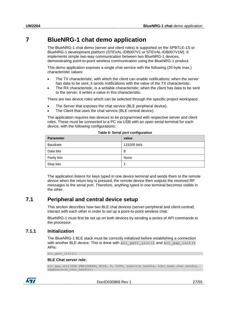
The application requires two devices to be programmed with respective server and client roles. These must be connected to a PC via USB with an open serial terminal for each device, with the following configurations:
Table 6: Serial port configuration
Parameter value
Baudrate 115200 bit/s
Data bits 8
Parity bits None
Stop bits 1
The application listens for keys typed in one device terminal and sends them to the remote device when the return key is pressed; the remote device then outputs the received RF messages to the serial port. Therefore, anything typed in one terminal becomes visible in the other.
7.1 Peripheral and central device setup
This section describes how two BLE chat devices (server-peripheral and client-central) interact with each other in order to set up a point-to-point wireless chat.
BlueNRG-1 must first be set up on both devices by sending a series of API commands to the processor.
7.1.1 Initialization
The BlueNRG-1 BLE stack must be correctly initialized before establishing a connection
with another BLE device. This is done with aci_gatt_init() and aci_gap_init()
APIs:
aci_gatt_init();
BLE Chat server role:
aci_gap_init(GAP_PERIPHERAL_ROLE, 0, 0x08, &service_handle, &dev_name_char_handle,
&appearance_char_handle);
BlueNRG-1 chat demo application UM2264
28/55 DocID030868 Rev 1
BLE Chat client role:
aci_gap_init(GAP_CENTRAL_ROLE, 0, 0x08, &service_handle, &dev_name_char_handle,
&appearance_char_handle);
Peripheral and central BLE roles must be specified in the aci_gap_init() command.
See the BlueNRG-1 BLE stack API documentation for more information on these and following commands.
7.1.2 Add service and characteristics
The chat service is added to the BLE chat server device via:
aci_gatt_add_service(UUID_TYPE_128, &service_uuid, PRIMARY_SERVICE,
7,&chatServHandle);
Where service_uuid is the private service 128-bit UUID allocated for the chat service
(Primary service). The command returns the service handle in chatServHandle. The TX
characteristic is added using the following command on the BLE Chat server device:
aci_gatt_add_char(chatServHandle, UUID_TYPE_128, &charUuidTX, 20, CHAR_PROP_NOTIFY,
ATTR_PERMISSION_NONE, 0, 16, 1, &TXCharHandle);
Where charUuidTX is the private characteristic 128-bit UUID allocated for the TX
characteristic (notify property). The characteristic handle is returned on the
TXCharHandle variable.
The RX characteristic is added using the following command on the BLE Chat server device:
aci_gatt_add_char(chatServHandle, UUID_TYPE_128, &charUuidRX, 20,
CHAR_PROP_WRITE|CHAR_PROP_WRITE_WITHOUT_RESP, ATTR_PERMISSION_NONE,
GATT_SERVER_ATTR_WRITE,16, 1, &RXCharHandle);
Where charUuidRX is the private characteristic 128-bit UUID allocated for the RX
characteristic (write property). The characteristic handle is returned on the RXCharHandle
variable.
See the BlueNRG-1 BLE stack API documentation for more information on these and following commands.
7.1.3 Enter connectable mode
The server device uses GAP API commands to enter the general discoverable mode:
aci_gap_set_discoverable(ADV_IND, 0, 0, PUBLIC_ADDR, NO_WHITE_LIST_USE,8,local_name,
0, NULL, 0, 0);
The local_name parameter contains the name presented in advertising data, as per
Bluetooth core specification version 4.2, Vol. 3, Part C, Ch. 11.
7.1.4 Connection with central device
Once the server device is discoverable by the BLE chat client device, the client device uses
aci_gap_create_connection()to connect with the BLE chat server device:
aci_gap_create_connection(0x4000, 0x4000, PUBLIC_ADDR, bdaddr, PUBLIC_ADDR, 40, 40,
0, 60, 2000 , 2000);
Where bdaddr is the peer address of the client device.
Once the two devices are connected, you can set up corresponding serial terminals and type messages in either of them. The typed characters are stored in two respective buffers and when the return key is pressed:
UM2264 BlueNRG-1 chat demo application
DocID030868 Rev 1 29/55
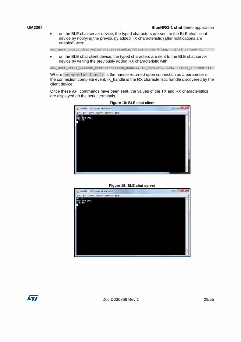
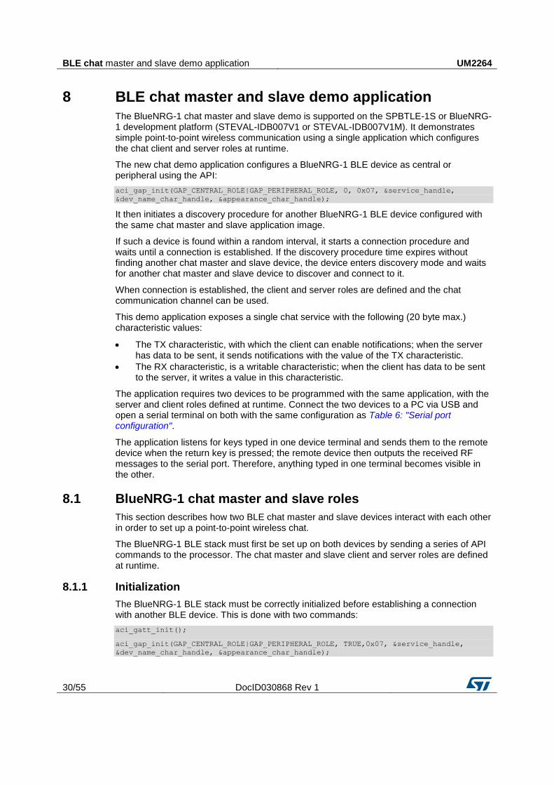
on the BLE chat server device, the typed characters are sent to the BLE chat client device by notifying the previously added TX characteristic (after notifications are enabled) with:
aci_gatt_update_char_value(chatServHandle,TXCharHandle,0,len, (uint8_t*)cmd+j);
on the BLE chat client device, the typed characters are sent to the BLE chat server device by writing the previously added RX characteristic with:
aci_gatt_write_without_resp(connection_handle, rx_handle+1, len, (uint8_t *)cmd+j);
Where connection_handle is the handle returned upon connection as a parameter of
the connection complete event, rx_handle is the RX characteristic handle discovered by the client device.
Once these API commands have been sent, the values of the TX and RX characteristics are displayed on the serial terminals.
Figure 18: BLE chat client
Figure 19: BLE chat server
BLE chat master and slave demo application UM2264
30/55 DocID030868 Rev 1
8 BLE chat master and slave demo application
The BlueNRG-1 chat master and slave demo is supported on the SPBTLE-1S or BlueNRG-1 development platform (STEVAL-IDB007V1 or STEVAL-IDB007V1M). It demonstrates simple point-to-point wireless communication using a single application which configures the chat client and server roles at runtime.
The new chat demo application configures a BlueNRG-1 BLE device as central or peripheral using the API:
aci_gap_init(GAP_CENTRAL_ROLE|GAP_PERIPHERAL_ROLE, 0, 0x07, &service_handle,
&dev_name_char_handle, &appearance_char_handle);
It then initiates a discovery procedure for another BlueNRG-1 BLE device configured with the same chat master and slave application image.
If such a device is found within a random interval, it starts a connection procedure and waits until a connection is established. If the discovery procedure time expires without finding another chat master and slave device, the device enters discovery mode and waits for another chat master and slave device to discover and connect to it.
When connection is established, the client and server roles are defined and the chat communication channel can be used.
This demo application exposes a single chat service with the following (20 byte max.) characteristic values:
The TX characteristic, with which the client can enable notifications; when the server has data to be sent, it sends notifications with the value of the TX characteristic.
The RX characteristic, is a writable characteristic; when the client has data to be sent to the server, it writes a value in this characteristic.
The application requires two devices to be programmed with the same application, with the server and client roles defined at runtime. Connect the two devices to a PC via USB and open a serial terminal on both with the same configuration as Table 6: "Serial port configuration".
The application listens for keys typed in one device terminal and sends them to the remote device when the return key is pressed; the remote device then outputs the received RF messages to the serial port. Therefore, anything typed in one terminal becomes visible in the other.
8.1 BlueNRG-1 chat master and slave roles
This section describes how two BLE chat master and slave devices interact with each other in order to set up a point-to-point wireless chat.
The BlueNRG-1 BLE stack must first be set up on both devices by sending a series of API commands to the processor. The chat master and slave client and server roles are defined at runtime.
8.1.1 Initialization
The BlueNRG-1 BLE stack must be correctly initialized before establishing a connection with another BLE device. This is done with two commands:
aci_gatt_init();
aci_gap_init(GAP_CENTRAL_ROLE|GAP_PERIPHERAL_ROLE, TRUE,0x07, &service_handle,
&dev_name_char_handle, &appearance_char_handle);
UM2264 BLE chat master and slave demo application
DocID030868 Rev 1 31/55
The BLE peripheral and central roles are specified in the aci_gap_init() command.
See the BlueNRG-1 BLE API documentation for more information on these and following commands.
8.1.2 Add service and characteristics
Refer to Section 7.1.2: "Add service and characteristics".
8.1.3 Start discovery procedure
To find another BlueNRG-1 BLE chat master and slave device in discovery mode, a discovery procedure must be started via:
aci_gap_start_general_discovery_proc(0x4000, 0x4000, 0x00, 0x00);
8.1.4 Enter connectable mode
The following GAP API command is used for entering general discoverable mode:
aci_gap_set_discoverable(ADV_IND, 0x90, 0x90, PUBLIC_ADDR, NO_WHITE_LIST_USE,
sizeof(local_name), local_name, 0, NULL, 0x6, 0x8);
8.1.5 Connection with chat master and slave client device
In the above mentioned discovery and mode assignment procedures, the two chat master and slave applications assume respective client and server roles at runtime. During this initial configuration phase, when a chat master and slave device is placed in discoverable mode and it is found by the other chat master and slave device performing a discovery procedure, a Bluetooth low energy connection is created and the device roles are defined.
The following GAP API command is used for connecting to the discovered device:
aci_gap_create_connection(0x4000, 0x4000,device_found_address_type,
device_found_address, PUBLIC_ADDR, 40, 40, 0, 60, 2000 , 2000);
Where device_found_address_type is the address type of the discovered chat master
and slave and device_found_address is the peer address of the discovered chat
master and slave device.
Once the two devices are connected, you can set up corresponding serial terminals and type messages in either of them. The typed characters are stored in two respective buffers and when the return key is pressed:
On the BLE chat master-and-slave server device, the typed characters are sent to the master-and-slave client device by notifying the previously added TX characteristic (after notifications have been enabled). This is done via:
aci_gatt_update_char_value(chatServHandle, TXCharHandle, 0, len, (uint8_t *)cmd+j);
On the master-and-slave client device, the typed characters are sent to the master-and-slave server device, by writing the previously added RX characteristic. This is done via:
aci_gatt_write_without_resp (connection_handle, rx_handle +1, len, (uint8_t
*)cmd+j);
Where connection_handle is the handle returned upon connection as a parameter of
the connection complete event, rx_handle is the RX characteristic handle discovered by
the client device.
Once these API commands have been sent, the values of the TX and RX characteristics are displayed on the serial terminals.
BlueNRG-1 remote control demo application UM2264
32/55 DocID030868 Rev 1
9 BlueNRG-1 remote control demo application
The BlueNRG-1 BLE remote control application is supported on the SPBTLE-1S or BlueNRG-1 development platforms (STEVAL-IDB007V1or STEVAL-IDB007V1M). It demonstrates how to control a remote device (like an actuator) using a BlueNRG-1 device.
This application periodically broadcasts temperature values that can be read by any device. The data is encapsulated in a manufacturer-specific AD type and the content (besides the manufacturer ID, i.e., 0x0030 for STMicroelectronics) is as follows:
Table 7: BLE remote advertising data
Byte 0 Byte 1 Byte2
App ID (0x05) Temperature value (little-endian)
The temperature value is given in tenths of degrees Celsius.
The device is also connectable and exposes a characteristic used to control LEDs DL1, DL2 and DL3 on the BlueNRG-1 platform. The value of this characteristic is a bitmap of 1 byte. Each bit controls one of the LEDs:
bit 0 is the status of LED DL1
bit 1 is the status of LED DL2
bit 2 is the status of LED DL3
A remote device can therefore connect and write this byte to change or read the status of these LEDs (1 for LED ON, 0 for LED OFF).
The peripheral disconnects after a timeout (DISCONNECT_TIMEOUT) to prevent a central
device remaining connected to the device indefinitely.
Security is not enabled by default, but this can be changed with ENABLE_SECURITY (refer
to file BLE_RC_main.h). When security is enabled, the central device must be authenticated before reading or writing the device characteristic.
To interact with a device configured as a BlueNRG-1 BLE remote control, another BLE device (a BlueNRG-1 or any Bluetooth® smart ready device) can be used to detect and view broadcast data.
To control one of the LEDs, the device has to connect to a BlueNRG-1 BLE remote control device and write in the exposed control point characteristic. The Service UUID is ed0ef62e-9b0d-11e4-89d3-123b93f75cba. The control point characteristic UUID is ed0efb1a-9b0d-11e4-89d3-123b93f75cba.
9.1 BLE remote control application setup
This section describes how to configure a BlueNRG-1 device to acting as a remote control device.
9.1.1 Initialization
The BlueNRG-1 BLE stack must be correctly initialized before establishing a connection with another Bluetooth LE device. This is done with two commands:
aci_gatt_init();
aci_gap_init(GAP_PERIPHERAL_ROLE, 0, 0x07, &service_handle, &dev_name_char_handle,
&appearance_char_handle);
UM2264 BlueNRG-1 remote control demo application
DocID030868 Rev 1 33/55
See BlueNRG-1 BLE stack API documentation for more information on these and following commands.
9.1.2 Define advertising data
The BLE remote control application advertises certain manufacturing data as follows:
/* Set advertising device name as Node */
const uint8_t scan_resp_data[] = {0x05,AD_TYPE_COMPLETE_LOCAL_NAME,'N','o','d','e'}
/* Set scan response data */
hci_le_set_scan_response_data(sizeof(scan_resp_data),scan_resp_data);
/* Set Undirected Connectable Mode */
aci_gap_set_discoverable(ADV_IND, (ADV_INTERVAL_MIN_MS*1000)/625,
(ADV_INTERVAL_MAX_MS*1000)/625, PUBLIC_ADDR, NO_WHITE_LIST_USE, 0, NULL, 0, NULL, 0,
0);
/* Set advertising data */
hci_le_set_advertising_data(sizeof(adv_data),adv_data);
On the BlueNRG-1 development platform (STEVAL-IDB007V1), the temperature sensor
value is set in the adv_data variable.
9.1.3 Add service and characteristics
The BLE Remote Control service is added via:
aci_gatt_add_service(UUID_TYPE_128, &service_uuid, PRIMARY_SERVICE, 7,
&RCServHandle);
Where service_uuid is the private service 128-bit UUID allocated for the BLE remote
service (ed0ef62e-9b0d-11e4-89d3-123b93f75cba).
The command returns the service handle in RCServHandle.
The BLE remote control characteristic is added using the following command:
#if ENABLE_SECURITY
aci_gatt_add_char(RCServHandle, UUID_TYPE_128, &controlPointUuid, 1,
CHAR_PROP_READ|CHAR_PROP_WRITE|CHAR_PROP_WRITE_WITHOUT_RESP|CH AR_PROP_SIGNED_WRITE,
ATTR_PERMISSION_AUTHEN_READ|ATTR_PERMISSION_AUTHEN_WRITE,
GATT_NOTIFY_ATTRIBUTE_WRITE,16,1,&controlPointHandle);
#else
aci_gatt_add_char(RCServHandle, UUID_TYPE_128, &controlPointUuid, 1,
CHAR_PROP_READ|CHAR_PROP_WRITE|CHAR_PROP_WRITE_WITHOUT_RESP, ATTR_PERMISSION_NONE,
GATT_NOTIFY_ATTRIBUTE_WRITE, 16, 1,&controlPointHandle);
#endif
Where controlPointUuid is the private characteristic 128-bit UUID allocated for BLE
remote control characteristic (ed0efb1a-9b0d-11e4-89d3-123b93f75cba) and
controlPointHandle is the BLE remote control characteristic handle.
If security is enabled, the characteristic properties must be set accordingly to enable
authentication on controlPointUuid characteristic read and write.
9.1.4 Connection with a BLE Central device
When connected to a BLE central device (another BlueNRG-1 or any Bluetooth® smart
ready device), the controlPointUuid characteristic is used to control the BLE remote
control platform LED. Each time a write operation is performed on controlPointUuid,
the aci_gatt_attribute_modified_event() callback is raised and the selected
LEDs are turned on or off.
BlueNRG-1 sensor profile demo UM2264
34/55 DocID030868 Rev 1
10 BlueNRG-1 sensor profile demo
The BlueNRG-1 sensor profile demo is supported on the BlueNRG-1 or SPBTLE-1S development platform (STEVAL-IDB007V1 or STEVAL-IDB007V1M). It implements a proprietary, Bluetooth low energy (BLE) sensor profile.
This example is useful for building new profiles and applications that use the BlueNRG-1 SoC. The GATT profile is not compliant with any existing specifications as the purpose of this project is to simply demonstrate how to implement a given profile.
This profile exposes the acceleration and environmental services.
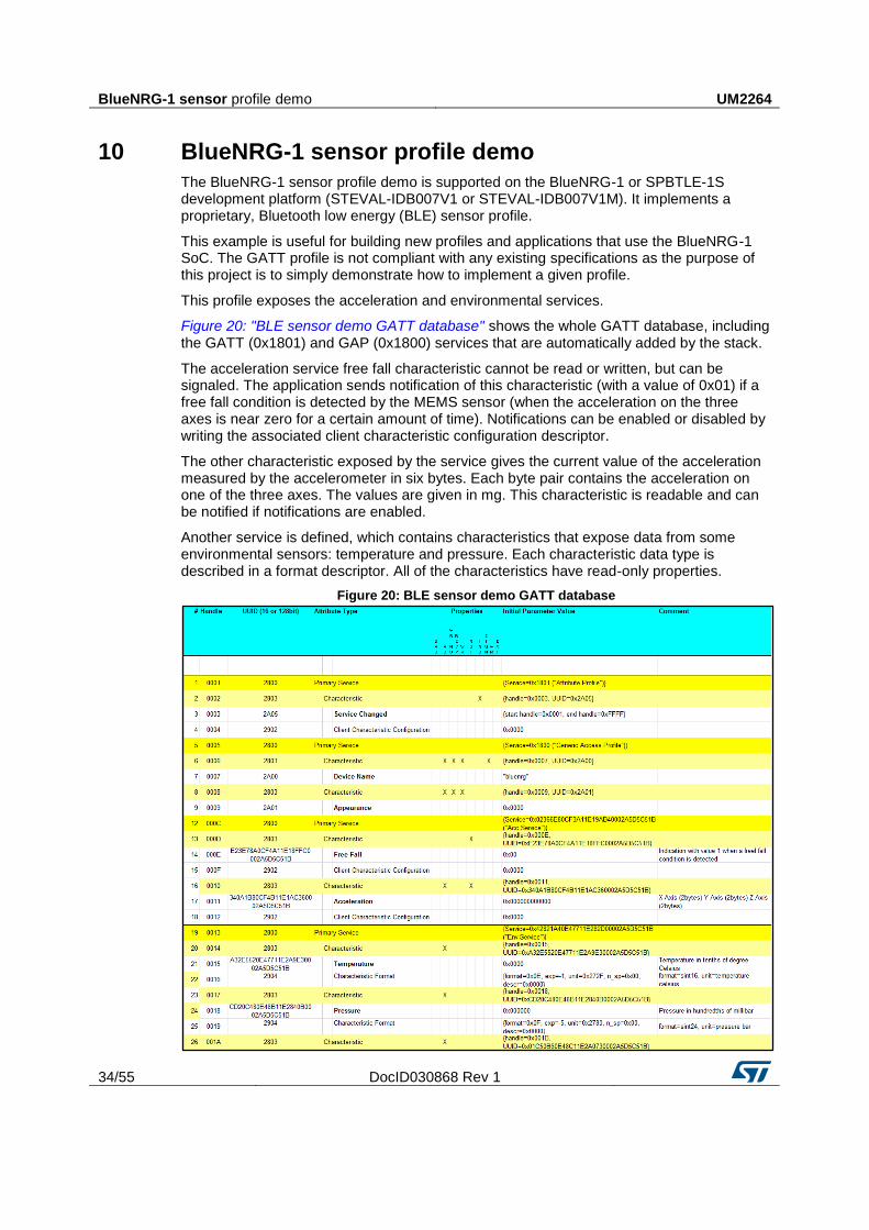
Figure 20: "BLE sensor demo GATT database" shows the whole GATT database, including the GATT (0x1801) and GAP (0x1800) services that are automatically added by the stack.
The acceleration service free fall characteristic cannot be read or written, but can be signaled. The application sends notification of this characteristic (with a value of 0x01) if a free fall condition is detected by the MEMS sensor (when the acceleration on the three axes is near zero for a certain amount of time). Notifications can be enabled or disabled by writing the associated client characteristic configuration descriptor.
The other characteristic exposed by the service gives the current value of the acceleration measured by the accelerometer in six bytes. Each byte pair contains the acceleration on one of the three axes. The values are given in mg. This characteristic is readable and can be notified if notifications are enabled.
Another service is defined, which contains characteristics that expose data from some environmental sensors: temperature and pressure. Each characteristic data type is described in a format descriptor. All of the characteristics have read-only properties.
Figure 20: BLE sensor demo GATT database
UM2264 BlueNRG-1 sensor profile demo
DocID030868 Rev 1 35/55
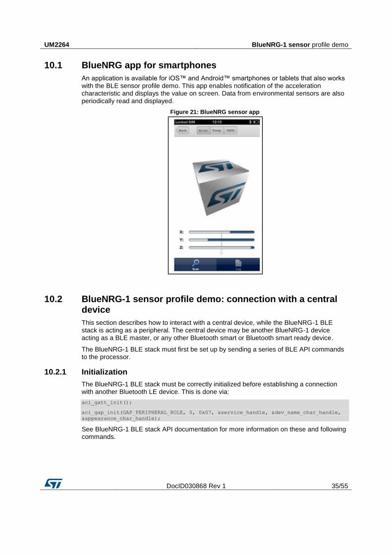
10.1 BlueNRG app for smartphones
An application is available for iOS™ and Android™ smartphones or tablets that also works with the BLE sensor profile demo. This app enables notification of the acceleration characteristic and displays the value on screen. Data from environmental sensors are also periodically read and displayed.
Figure 21: BlueNRG sensor app
10.2 BlueNRG-1 sensor profile demo: connection with a central device
This section describes how to interact with a central device, while the BlueNRG-1 BLE stack is acting as a peripheral. The central device may be another BlueNRG-1 device acting as a BLE master, or any other Bluetooth smart or Bluetooth smart ready device.
The BlueNRG-1 BLE stack must first be set up by sending a series of BLE API commands to the processor.
10.2.1 Initialization
The BlueNRG-1 BLE stack must be correctly initialized before establishing a connection with another Bluetooth LE device. This is done via:
aci_gatt_init();
aci_gap_init(GAP_PERIPHERAL_ROLE, 0, 0x07, &service_handle, &dev_name_char_handle,
&appearance_char_handle);
See BlueNRG-1 BLE stack API documentation for more information on these and following commands.
BlueNRG-1 sensor profile demo UM2264
36/55 DocID030868 Rev 1
10.2.2 Add service and characteristics
The BlueNRG-1 BLE stack has both server and client capabilities. A characteristic is an element in the server database where data is exposed, while a service contains one or more characteristics. The acceleration service is added with the following command:
aci_gatt_add_service(UUID_TYPE_128, &service_uuid, PRIMARY_SERVICE, 7,
&accServHandle);
The command returns the service handle on variable accServHandle. The free fall and
acceleration characteristics must now be added to this service thus:
aci_gatt_add_char(accServHandle, UUID_TYPE_128, &char_uuid, 1, CHAR_PROP_NOTIFY,
ATTR_PERMISSION_NONE, 16, 0, &freeFallCharHandle);
aci_gatt_add_char(accServHandle, UUID_TYPE_128, &char_uuid, 6,
CHAR_PROP_NOTIFY|CHAR_PROP_READ, ATTR_PERMISSION_NONE,
GATT_NOTIFY_READ_REQ_AND_WAIT_FOR_APPL_RESP, 16, 0, &accCharHandle);
The free fall and acceleration characteristics handles are returned on
freeFallCharHandle and accCharHandle variables respectively.
Similar steps are followed for adding the environmental sensor and relative characteristics.
10.2.3 Enter connectable mode
Use GAP API command to enter one of the discoverable and connectable modes:
aci_gap_set_discoverable(ADV_IND, (ADV_INTERVAL_MIN_MS*1000)/625,
(ADV_INTERVAL_MAX_MS*1000)/625, STATIC_RANDOM_ADDR, NO_WHITE_LIST_USE
sizeof(local_name), local_name, 0, NULL, 0, 0);
Where
local_name[] = {AD_TYPE_COMPLETE_LOCAL_NAME,'B','l','u','e','N','R','G'};
The local_name parameter contains the name presented in advertising data, as per
Bluetooth core specification version, Vol. 3, Part C, Ch. 11.
10.2.4 Connection with central device
Once the BlueNRG-1 BLE stack is placed in discoverable mode, it can be detected by a central device. The smartphone app described in Section 10.1: "BlueNRG app for smartphones" is designed to interact with the sensor profile demos (it also supports the BlueNRG-1 device).
Any Bluetooth smart or Bluetooth smart ready device like a smartphone can connect to the BlueNRG-1 BLE sensor profile demo.
For example, the LightBlue application in Apple Store® (iPhone® versions 4S/5 and above) can connect to the sensor profile device. When you use the LightBlue application, detected devices appear on the screen with the BlueNRG name. By tapping on the box to connect to the device, a list of all the available services is shown on the screen; tapping a service shows the characteristics for that service.
The acceleration characteristic can be notified using the following command:
aci_gatt_update_char_value(accServHandle, accCharHandle, 0, 6, buff);
Where buff is a variable containing the three axes acceleration values.
Once this API command has been sent, the new value of the characteristic is displayed on the phone.
UM2264 BlueNRG-1 sensor profile central demo
DocID030868 Rev 1 37/55
11 BlueNRG-1 sensor profile central demo
The BlueNRG-1 sensor profile central demo is supported on the BlueNRG-1 or SPBTLE-1S development platforms (STEVAL-IDB007V1 or STEVAL-IDB007V1M). It implements a basic version of the BlueNRG-1 BLE Sensor Profile Central role which emulates the BlueNRG-1 Sensor Demo applications available for smartphones (iOS and Android).
This application configures a BlueNRG-1 device as a BlueNRG-1 Sensor device, Central role which is able to find, connect and properly configure the free fall, acceleration and environment sensor characteristics provided by a BlueNRG-1 development platform configured as a BlueNRG-1 Sensor device, Peripheral role (refer to Section 10: "BlueNRG-1 sensor profile demo").
This application uses a new set of APIs allowing to perform the following operations on a BlueNRG-1 Master/Central device:
Master Configuration Functions
Master Device Discovery Functions
Master Device Connection Functions
Master Discovery Services, Characteristics Functions
Master Data Exchange Functions
Master Security Functions
Master Common Services Functions
These APIs are provided through a binary library and they are fully documented on available doxygen documentation within the BlueNRG-1 DK SW package. The following master/central binary libraries are provided on Bluetooth_LE\Profile_Framework_Central\library folder:
master_library_bluenrg1.lib for IAR and Keil toolchains
libmaster_library_bluenrg1.a for Atollic toolchain
BlueNRG-1 HID/HOGP demonstration application UM2264
38/55 DocID030868 Rev 1
12 BlueNRG-1 HID/HOGP demonstration application
The BLE HID/HOGP demonstration applications are supported by the BlueNRG-1 or SPBTLE-1S development platforms (STEVAL-IDB007V1 or STEVAL-IDB007V1M). It demonstrates a BlueNRG-1 device using the standard HID/HOGP Bluetooth low energy application profile. Keyboard and mouse demo examples are provided.
12.1 BLE HID/HOGP mouse demonstration application
The BlueNRG-1 HID mouse application implements a basic HID mouse with two buttons compliant with the standard HID/HOGP BLE application profile.
The HID mouse device is named ‘STMouse’ in the central device list.
The mouse movements are provided by the 3D accelerometer and 3D gyroscope on the BLE development platform.
The left button is the ‘PUSH1’ button
The right button is the ‘PUSH2’ button
If the HID mouse is not used for two minutes, it closes the connection and enters deep sleep mode. This idle connection timeout can be changed from the application. To exit deep sleep mode, press the left ‘PUSH1 button or reset the platform.
12.2 BLE HID/HOGP keyboard demonstration application
The BlueNRG-1 HID keyboard application implements a basic HID keyboard compliant with the standard HID/HOGP BLE application profile.
The HID mouse device is named ‘STKeyboard’ in the central device list.
To successfully complete the bonding and pairing procedure, insert the PIN: 123456.
To use the HID keyboard:
Connect the BlueNRG-1 development platform to a PC USB port
Open a HyperTerminal window (115200, 8, N,1)
Put the cursor focus on the HyperTerminal window
The keys that are sent to the central device using the HID/HOGP BLE application profile are also shown on the HyperTerminal window
If the HID keyboard is not used for two minutes, it closes the connection and enters deep sleep mode. This idle connection timeout can be changed from the application. To exit deep sleep mode, press the left ‘PUSH1 button or reset the platform.
UM2264 BlueNRG-1 throughput demonstration application
DocID030868 Rev 1 39/55
13 BlueNRG-1 throughput demonstration application
The BlueNRG-1 throughput demonstration application provides some basic throughput demonstration applications to provide some reference figures regarding the achievable Bluetooth low energy data rate using the BlueNRG-1 device.
The throughput application scenarios provided are:
1. Unidirectional scenario: the server device sends characteristic notifications to a client device.
2. Bidirectional scenario: the server device sends characteristic notifications to a client device and client device sends write without response characteristics to the server device.
The throughput application exposes one service with two (20 byte max.) characteristic values:
The TX characteristic, with which the client can enable notifications; when the server has data to be sent, it sends notifications with the value of the TX characteristic.
The RX characteristic, is a writable characteristic; when the client has data to be sent to the server, it writes a value in this characteristic.
The device roles which can be selected are:
1. Server, which exposes the service with the TX, RX characteristics (BLE peripheral device)
2. Client, which uses the service TX, RX characteristics (BLE central device).
Each device role has two instances for each throughput scenario (unidirectional, bidirectional).
The BlueNRG-1 throughput demonstration applications are supported by the BlueNRG-1 development platform (STEVAL-IDB007V1).
13.1 BLE unidirectional throughput scenario
The unidirectional throughput scenario lets you perform a unidirectional throughput test where a server device sends notification to a client device.
To run this scenario:
Program the client unidirectional application on one BLE platform and reset it. The platform is seen on the PC as a virtual COM port.
Open the port in a serial terminal emulator (the required serial port baudrate is 921600)
Program the server unidirectional application on a second BLE platform and reset it.
The two platforms try to establish a connection; if successful, the slave continuously sends notifications of TX characteristic (20 bytes) to the client.
After every 500 packets, the measured application unidirectional throughput is displayed.
13.2 BLE bidirectional throughput scenario
The bidirectional throughput scenario lets you perform a bidirectional throughput test where the server device sends notifications to a client device and client device sends write without response characteristics to the server device.
To run this scenario:

BlueNRG-1 throughput demonstration application UM2264
40/55 DocID030868 Rev 1
Program the client bidirectional application on one BLE platform and reset it. The platform is seen on the PC as a virtual COM port.
Open the related port in a serial terminal emulator (the required serial port baudrate is 921600)
Program the server bidirectional application on a second BLE platform and reset it.
Open the related port in a serial terminal emulator (the required serial port baudrate is 921600)
The two platforms try to establish a connection; if successful, the slave device continuously sends notifications of TX characteristic (20 bytes) to the client device and the client device continuously sends write without responses of the RX characteristic (20 bytes) to the server device.
After every 500 packets, the measured application bidirectional throughput is displayed.
UM2264 BLE notification consumer demonstration application
DocID030868 Rev 1 41/55
14 BLE notification consumer demonstration application
The BLE ANCS demonstration application configures a BlueNRG-1 device or SPBTLE-1S module as a BLE notification consumer, which facilitates Bluetooth accessory access to the many notifications generated on a notification provider.
After reset, the demo places the BlueNRG-1 device in advertising with device name "ANCSdemo" and sets the BlueNRG-1 authentication requirements to enable bonding.
When the device is connected and bonded with a notification provider, the demo configures the BlueNRG-1 notification consumer device to discover the service and the characteristics of the notification provider. When the setup phase is complete, the BlueNRG-1 device is configured as a notification consumer able to receive the notifications sent from the notification provider.
The BLE notification consumer demonstration application is supported by the BlueNRG-1 development platform (STEVAL-IDB007V1).
BlueNRG-1 peripheral driver examples UM2264
42/55 DocID030868 Rev 1
15 BlueNRG-1 peripheral driver examples
The BlueNRG-1 peripheral driver example applications are supported by the BlueNRG-1 or SPBTLE-1S development platform (STEVAL-IDB007V1 or STEVAL-IDB007V1M). The kit contains a set of examples demonstrating how to use the BlueNRG-1 device peripheral drivers (ADC, GPIOs, I²C, RTC, SPI, Timers, UART and WDG).
15.1 ADC examples
ADC polling: conversion is managed through the polling of the status register. The systick timer is used to have a delay of 100 ms between two samples. Each sample from ADC is printed through UART (USB-to-SERIAL must be connected to the PC). The default input is the differential ADC1-ADC2.
ADC DMA: conversion is managed through the ADC DMA channel. The systick timer is used to have a delay of 100 ms between two samples. Each sample from ADC is printed through UART (USB-to-SERIAL must be connected to the PC).
ADC PDM: this example shows a PDM stream processor from a MEMS microphone (MP34DT01-M i.e.) to UART. The application also supports the MEMS microphone MP34DT01-M available on X-NUCLEO-CCA02MM1 board (refer to related BlueNRG-1 DK SW package ADC PDM doxygen documentation for HW connections setup).
User is requested to connect the BlueNRG-1 STEVAL-IDB007V1 to a PC USB port and open PuTTY serial terminal [512000, 8-N-1-N]. PuTTY serial terminal has to be configured for storing the captured data on a log file. After the data have been captured, the PC Audacity tool can been opened for importing the streamed data, following these steps:
File/Import/Raw Data.
Open the log data.
Configure as follows:
Encoding: Signed 16-bit PCM.
Byte order: Little-endian.
Channels: 1 Channel (Mono).
Sample rate: 8000 (default, 16 kbps is supported by changing the firmware symbol FS in ADC_PDM_main.c)
Press the button Import.
Play the audio.
Due to the fact that the output data format is 2-bytes (B1B2), it is possible that the serial terminal gets as first byte, half data (B2). This first byte must be removed from the log file.
15.2 GPIO examples
Input interrupt: demonstrates the use of GPIO input interrupts.
The PUSH1 button (IO13) is configured to generate the interrupt event on both edges of the input signal. LED DL1 is toggled ON if the level is high and OFF if low.
The PUSH2 button (IO5) is configured to generate the interrupt event on the rising edge of the input signal. LED DL2 is toggled ON/OFF at each rising edge event.
IO toggle: demonstrates GPIO state changes by toggling LEDs DL1 and DL2 every 500 ms.
UM2264 BlueNRG-1 peripheral driver examples
DocID030868 Rev 1 43/55
IO wakeup: demonstrates device wakeup from standby mode using the GPIO interrupt.
The PUSH1 button (IO13) is configured to generate the interrupt event on both edges of the input signal. LED DL2 is toggled, the system becomes active and LED DL1 is toggled by the systick interrupt service routine every 500 ms.
Once the device is in standby, there is no way to open a connection with the debug tool or download new code as the clocks are down and the system voltages are at their minimum values. It is necessary to wake-up the system first, which is why the IO9 (SDW clock signal) is wake-up event. In this case, any connection attempt from the debugger wakes up the system.
15.3 I²C examples
In all of the following examples, I²C is configured in master mode and its clock frequency is set to 10 kHz.
Master polling: I²C communication is controlled by polling the I²C status register content. This example involves a master board with Master_Polling firmware code and a slave board with Slave_Polling firmware.
The Master board has a small command line interface through UART (USB-to-SERIAL must be connected to the PC), which you can use to read and change the LED status of the slave board. I²C is used to transfer the information and change the status of the LEDs on the slave board.
Slave polling: I²C communication is controlled by polling the I²C status register content. This also involves a master and a slave board with respective Master_Polling and Slave_Polling firmware. The slave board receives read and change requests for the LEDs via I²C.
Master sensor: I²C communication is controlled by polling of I²C status register content, interrupts or DMA (three different configurations). In this example, the environmental sensor LPS25HB is configured to provide output data at 1 Hz. The BlueNRG-1 polls the status register of the sensor and prints available pressure and temperature data via UART (USB-to-SERIAL must be connected to the PC).
15.4 Micro examples
Hello world: example for the basic ‘BlueNRG-1 Hello World’ application. Connect the BlueNRG-1 platform to a PC USB port and open a specific PC tool/program (like Tera Term): the "Hello World: BlueNRG-1 is here!" message is displayed.
Sleep test: this test provides an example for the following BlueNRG-1 sleep modes:
SLEEPMODE_WAKETIMER places the BlueNRG-1 in deep sleep with the timer clock sources running. The wakeup sources are typing any character on the keyboard, the PUSH1 button or the sleep timer configured with a timeout of 5 s.
The SLEEPMODE_NOTIMER places the BlurNRG-1 in deep sleep with the sleep timer clock sources turned off. The only wakeup sources are typing any character on the keyboard and the PUSH1 button.
The demo supports some user commands:
s: SLEEPMODE_NOTIMER - wake on UART/PUSH1
t: SLEEPMODE_WAKETIMER - wake on UART/timeout 5 s/PUSH1
l: Toggle led DL1
p: Print the ‘Hello World’ message
r: Reset the BlueNRG-1 device
?: Display this help menu
BlueNRG-1 peripheral driver examples UM2264
44/55 DocID030868 Rev 1
PUSH1: toggle LED DL1
15.5 RTC examples
Clock watch: implements both RTC timer and RTC clockwatch.
The RTC timer generates the 500 ms interrupt interval. The LED DL1 state is toggled in the RTC interrupt handler to signal proper RTC timer operation.
The RTC clockwatch is also enabled with the system time and date set to December 1st 2014, 23 h 59 m 31 s. The RTC clockwatch match registers are then set to December 2nd 2014, 0 h 0 m 1 s. As soon as the RTC clockwatch data register and match registers coincide (30 s after device power up), the RTC clockwatch match interrupt is generated and LED DL2 is toggled to signal the event.
Time base: the RTC is configured in the periodic timer mode, the load register (RTC_TLR1) value is set and the RTC is enabled. Whenever the RTC timer reaches the value 0x00 it generates an interrupt event and the timer value is automatically re-loaded from the RTC_TLR1 register, which is set to generate the interrupt every 1 s. The LED DL1 is toggled at each interrupt event.
Time base pattern: periodic mode is used with a pattern configuration. The RTC is configured in the periodic timer mode and register RTC_TLR1 is set to generate a 1 s interval, while RTC_TLR2 is set to generate a 100 ms interval.
The RTC is then enabled and whenever the RTC timer reaches the value 0x00 it generates an interrupt and the timer value is automatically re-loaded from register RTC_TLR1 or RTC_TLR2 register depending on the pattern register setting.
The pattern size is set to 8 bits and the pattern is set to 0b11110010, so the RTC generates four intervals with the RTC_TLR1 value followed by two RTC_TLR2 value intervals. The pattern repeats itself and the RTC interrupt routine toggles LED DL1 (IO6).
15.6 SPI examples
The following SPI application examples are available:
Master polling: involves a master board with the Master_Polling firmware code and a slave board with the Slave_Polling firmware. The Master board has a small command line interface through UART (USB-to-SERIAL must be connected to the PC), which you can use to read and change the LED status of the slave board via SPI.
The SPI is configured in master mode and the SPI clock set to 100 kHz. The data is transferred in the Motorola format with an 8-bit data frame, with clock low when inactive (CPOL=0) and data valid on clock trailing edge (CPHA = 1).
Slave polling: SPI communication is controlled by polling the SPI status register content. This also involves a master and a slave board with respective Master_Polling and Slave_Polling firmware. The slave board receives read and change requests for the LEDs via SPI.
The SPI is configured in slave mode and the SPI clock set to 100 kHz. The data is transferred in the Motorola format with an 8-bit data frame, with clock low when inactive (CPOL=0) and data valid on clock trailing edge (CPHA = 1).
Master sensor: SPI communication is controlled by polling of the SPI status register content, interrupts or DMA (3 different configurations). SPI is used to communicate with the LSM6DS3 inertial sensor SPI interface. Whenever the sensor generates an IRQ, the accelerometer and gyroscope output data are read and printed through UART (USB-to-SERIAL must be connected to the PC).
UM2264 BlueNRG-1 peripheral driver examples
DocID030868 Rev 1 45/55
The SPI is configured in master mode and the SPI clock set to 100 kHz. The data is transferred in the Motorola format with an 8-bit data frame, with clock low when inactive (CPOL=0) and data valid on clock trailing edge (CPHA = 1).
Master DMA: SPI communication is controlled by DMA of the SPI status register content. It involves a master board with the Master_Dma firmware code and a slave board with the Slave_Dma firmware. The Master board has a small command line interface through UART (USB-to-SERIAL must be connected to the PC), which you can use to read and change the LED status of the slave board via SPI.
The SPI is configured in master mode and the SPI clock set to 100 kHz. The data is transferred in the Motorola format with an 8-bit data frame, with clock low when inactive (CPOL=0) and data valid on clock trailing edge (CPHA = 1).
Slave DMA: SPI communication is controlled by DMA of the SPI status register content. It involves a master board with the Master_Dma firmware code and a slave board with the Slave_Dma firmware. The slave board receives read and change requests for the LEDs via SPI.
The SPI is configured in slave mode and the SPI clock set to 100 kHz. The data is transferred in the Motorola format with an 8-bit data frame, with clock low when inactive (CPOL=0) and data valid on clock trailing edge (CPHA = 1).
15.7 SysTick examples
Time base: The interrupt service routine toggles the user LEDs at approximately 1 s intervals.
15.8 Timers examples
Mode 1: Timer/Counter 1 (TnCNT1) functions as the time base for the PWM timer and counts down at the clock rate selected by the Timer/Counter 1 clock selector. When an underflow occurs, the timer register is reloaded alternately from the TnCRA (first reload) and TnCRB registers and count down begins from the loaded value.
Timer/Counter 2 can be used as a simple system timer, an external-event counter, or a pulse-accumulate counter. Counter TnCNT2 counts down with the clock selected by the Timer/Counter 2 clock selector, and can be configured to generate an interrupt upon underflow.
MFTX1 and MFTX2 use prescaled clock as Timer/Counter 1. The IO2 pin is configured as output, generating a signal with 250 ms positive level and 500 ms negative level via MFTX1. The IO3 pin is configured as output, generating a signal with 50 ms positive level and 100 ms negative level via MFTX2.
Timer/Counter 1 interrupts upon reload are enabled for MFTX1 and MFTX2; interrupt routines toggle LED DL1 for MFTX1 and LED DL2 for MFTX2.
Mode 1a (pulse-train mode): the Timer/Counter 1 functions as PWM timer and Timer/Counter 2 is used as a pulse counter that defines the number of pulses to be generated.
In this example, MFTX2 is configured to generate 30 pulses with positive level of 500 ms and negative level of 250 ms. MFTX2 uses prescaled clock as Timer/Counter 1. The IO3 pin is configured as output generating the number of pulses configured.
Interrupts TnA and TnB are enabled and toggle GPIO 8 and 10, while Interrupt TnD is enabled and sets GPIO 7.
A software start trigger or external rising or falling edge start trigger can be selected. This example uses a software trigger which is generated after system configuration.

BlueNRG-1 peripheral driver examples UM2264
46/55 DocID030868 Rev 1
Timer/Counter 1 interrupts on reload are enabled for MFTX1. Interrupt routines toggle LED DL1 for MFTX2.
Mode 2 (dual-input capture mode): Timer/Counter 1 counts down with the selected clock and TnA and TnB pins function as capture inputs. Transitions received on the TnA and TnB pins trigger a transfer of timer content to the TnCRA and TnCRB registers, respectively. Timer/Counter 2 counts down with selected clock and can generate an interrupt on underflow.
In this example, MFTX1 is used. The CPU clock is selected as the clock signal for Timer/Counter 1 and a Prescaled clock is used as the clock source for Timer/Counter 2.
Sensitivity to falling edge is selected for TnA and TnB inputs; counter preset to 0xFFFF is disabled for both inputs.
The IO2 pin is internally connected to TnA input (MFTX1) and the IO3 pin is internally connected to TnB input (MFTX1).
Interrupts TnA and TnB are enabled and triggered by transitions on pins TnA and TnB, respectively. The interrupt routine records the value of TnCRA or TnCRB and calculates the period of the input signal every second interrupt.
Interrupt TnC is enabled and is triggered on each underflow of Timer/Counter1; it increments the underflow counter variables used to calculate the input signal period.
LED DL1 is toggled ON if a frequency of about 1 kHz is detected on IO2, and LED DL2 is toggled ON if a frequency of about 10 kHz is detected on IO3.
Mode 3 (dual independent timer/counter): the timer/counter is configured to operate as a dual independent system timer or dual external-event counter. Timer/Counter 1 can also generate a 50% duty cycle PWM signal on the TnA pin, while the TnB pin can be used as an external-event input or pulse-accumulate input, and serve as the clock source to either Timer/Counter 1 or Timer/Counter 2. Both counters can also be operated from the prescaled system clock.
In this example MFTX1 is used. The CPU clock is selected as the clock signal for Timer/Counter 1, while Timer/Counter 2 uses an external clock on TnB pin. Sensitivity to rising edge is selected for TnB input. Timer/Counter 1 is preset and reloaded to 5000, so the frequency of the output signal is 1 kHz. Timer/Counter 2 is preset and reloaded to 5.
The IO3 pin is internally connected to TnA input (MFTX1), while the IO2 pin is configured as output and configured as the PWM output from Timer/Counter 1.
The LED DL1 is toggled in the main program according to a variable which is changed in TnD interrupt routine. Interrupt TnA and TnD are enabled and are triggered on the underflow of Timer/Counter1 and Timer/Counter2 respectively.
Mode 4 (input-capture plus timer): is a combination of mode 3 and mode 2, and makes it possible to operate Timer/Counter 2 as a single input-capture timer, while Timer/Counter 1 can be used as a system timer as described above.
In this example, MFTX1 is used. The CPU clock is selected as the input clock for Timer/Counter 1 and Timer/Counter 2. Automatic preset is enabled for Timer/Counter 2.
The IO2 pin is internally connected to the TnB input (MFTX1), while the IO3 pin is configured as the output and configured as the PWM output from Timer/Counter 1.
Interrupt TnA is enabled and triggered on the underflow of Timer/Counter1; it sets a new value in the TnCRA register. Interrupt TnB in enabled and triggered when a transition on TnB input (input capture) is detected; it saves the TnCRB value. Interrupt TnD in enabled and it triggered on the underflow of Timer/Counter2.
UM2264 BlueNRG-1 peripheral driver examples
DocID030868 Rev 1 47/55
MFT timers: this example shows how configure peripherals MFT1, MFT2 and SysTick to generate three timer interrupts at different rate: MFT1 at 500 ms, MFT2 at 250 ms and SysTick at 1 second.
15.9 UART examples
DMA: IO8 and IO11 are configured as UART pins and DMA receive and transmit requests are enabled. Each byte received from UART is sent back through UART in an echo application (USB-to-SERIAL must be connected to the PC).
Interrupt: IO8 and IO11 are configured as UART pins and receive and transmit interrupts are enabled. Each byte received from UART is sent back through UART in an echo application (USB-to-SERIAL must be connected to the PC).
Polling: IO8 and IO11 are configured as UART pins. Each byte received from UART is sent back through UART in an echo application (USB-to-SERIAL must be connected to the PC).
15.10 WDG examples
Reset: demonstrates the watchdog functionality and using it to reboot the system when the watchdog interrupt is not serviced during the watchdog period (interrupt status flag is not cleared).
The watchdog is configured to generate the interrupt with a 15 s interval, then it is enabled and monitors the state of the PUSH1 button (IO13 pin). Any change on this pin triggers the watchdog counter to reload and restart the 15 s interval measurement.
If the IO13 pin state does not change during this interval, the watchdog generates an interrupt that is intentionally not cleared and therefore remains pending; the watchdog interrupt service routine is therefore called continuously and the system is stuck in the watchdog interrupt handler.
The chip is reset as it can no longer execute user code. The second watchdog timeout triggers system reboot as a new watchdog interrupt is generated while the previous interrupt is still pending. The application then starts measuring the 15 s interval again.
The three user LEDs are toggled at increasing frequencies until the board is reset or PUSH1 button is pressed, which restores the LEDs toggling frequency with the 15 s watchdog timer.
Wakeup: The watchdog timer is a 32-bit down counter that divides the clock input (32.768 kHz) and produces an interrupt whenever the counter reaches zero. The counter is then reloaded with the content of the WDT_LR register. If the interrupt status flag is not cleared and a new interrupt is generated, then the watchdog may generate a system reset.
This example demonstrates the use of the watchdog to periodically wake the system from standby mode using the watchdog interrupt. The watchdog is configured to generate the interrupt at 1 s intervals. The watchdog is then enabled and the system is switched to the standby mode. As soon as the watchdog interrupt is generated, the system wakes up, LED1 (IO6 pin) is toggled and the device returns to standby mode. The IO6 pin is therefore toggled every 1 s.
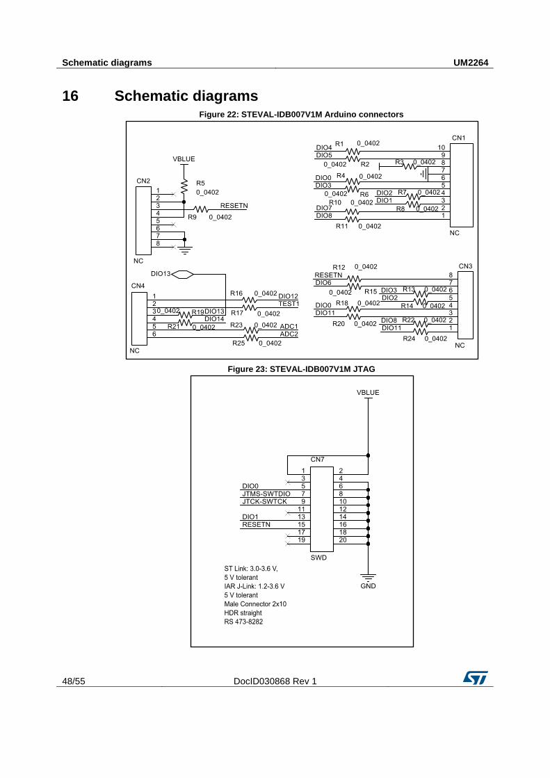
Schematic diagrams UM2264
48/55 DocID030868 Rev 1
16 Schematic diagrams Figure 22: STEVAL-IDB007V1M Arduino connectors
Figure 23: STEVAL-IDB007V1M JTAG
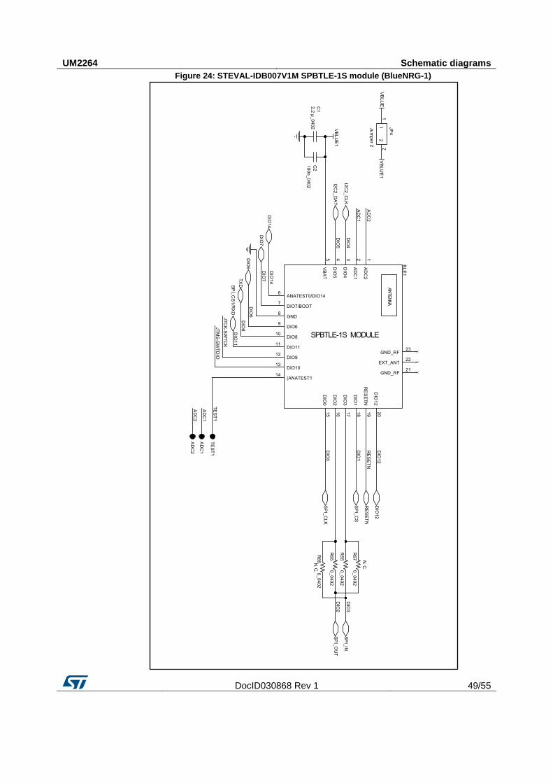
UM2264 Schematic diagrams
DocID030868 Rev 1 49/55
Figure 24: STEVAL-IDB007V1M SPBTLE-1S module (BlueNRG-1)
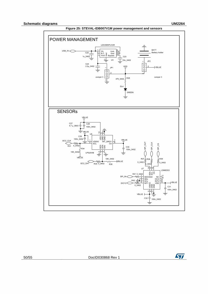
Schematic diagrams UM2264
50/55 DocID030868 Rev 1
Figure 25: STEVAL-IDB007V1M power management and sensors
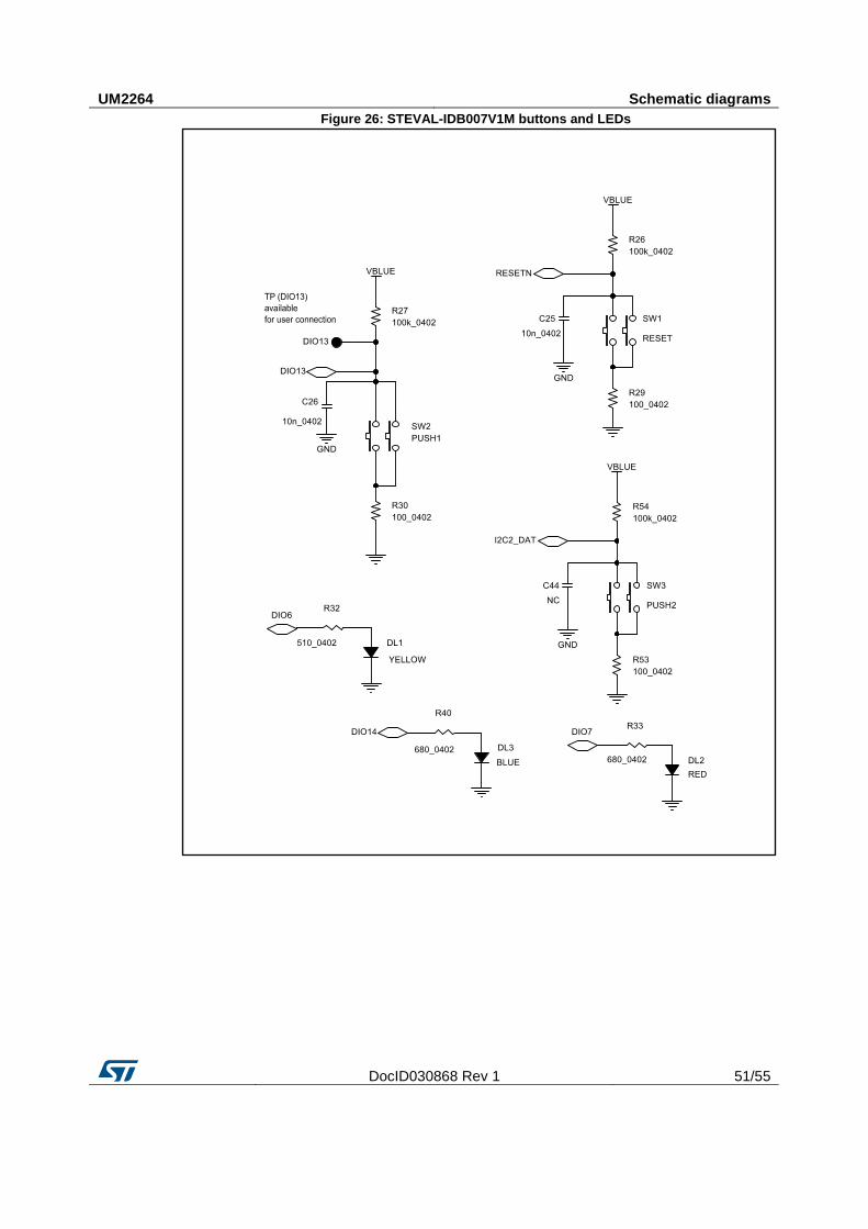
UM2264 Schematic diagrams
DocID030868 Rev 1 51/55
Figure 26: STEVAL-IDB007V1M buttons and LEDs
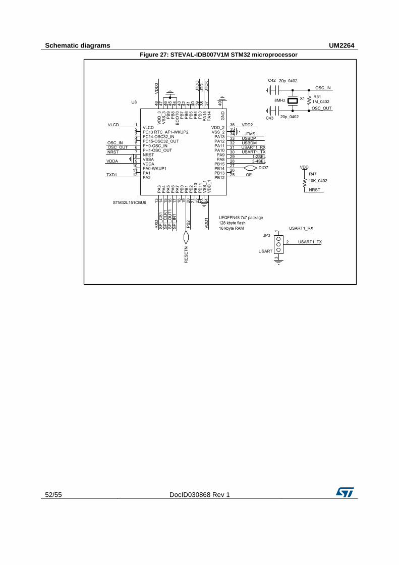
Schematic diagrams UM2264
52/55 DocID030868 Rev 1
Figure 27: STEVAL-IDB007V1M STM32 microprocessor
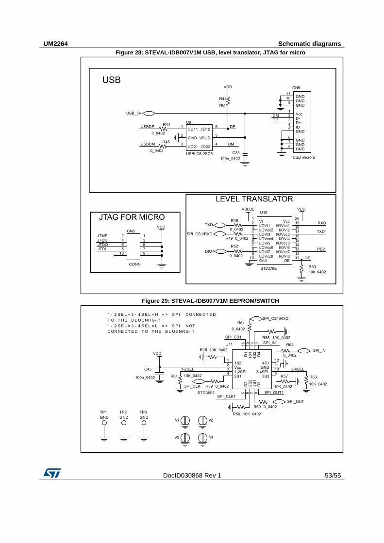
UM2264 Schematic diagrams
DocID030868 Rev 1 53/55
Figure 28: STEVAL-IDB007V1M USB, level translator, JTAG for micro
Figure 29: STEVAL-IDB007V1M EEPROM/SWITCH

Revision history UM2264
54/55 DocID030868 Rev 1
17 Revision history Table 8: Document revision history
Date Version Changes
25-Jul-2017 1 Initial release.

UM2264
DocID030868 Rev 1 55/55
IMPORTANT NOTICE – PLEASE READ CAREFULLY
STMicroelectronics NV and its subsidiaries (“ST”) reserve the right to make changes, corrections, enhancements, modifications , and improvements to ST products and/or to this document at any time without notice. Purchasers should obtain the latest relevant information on ST products before placing orders. ST products are sold pursuant to ST’s terms and conditions of sale in place at the time of order acknowledgement.
Purchasers are solely responsible for the choice, selection, and use of ST products and ST assumes no liability for application assistance or the design of Purchasers’ products.
No license, express or implied, to any intellectual property right is granted by ST herein.
Resale of ST products with provisions different from the information set forth herein shall void any warranty granted by ST for such product.
ST and the ST logo are trademarks of ST. All other product or service names are the property of their respective owners.
Information in this document supersedes and replaces information previously supplied in any prior versions of this document.
© 2017 STMicroelectronics – All rights reserved