Embed Size (px)
Citation preview

1
Geotechnical Summary Report Valdez Navigation Improvements – East Site
Valdez, Alaska August 2007
1. Introduction
Several preliminary subsurface investigations and analyses were performed to provide a general understanding of subsurface conditions within and near the East Site. This report presents a summary of the findings from those investigations and the analyses. The investigations include shallow test pits, test borings from previous explorations for the nearby Ship Escort Response Vessel System (SERVS) Dock and West Site, remote sensing by geophysical methods, and global stability analyses. These studies provide information to gain a general understanding of the surface and subsurface conditions within and near the project area. A detailed geotechnical investigation of the East Site will be conducted prior to the design of this project.
2. Site Location and Description
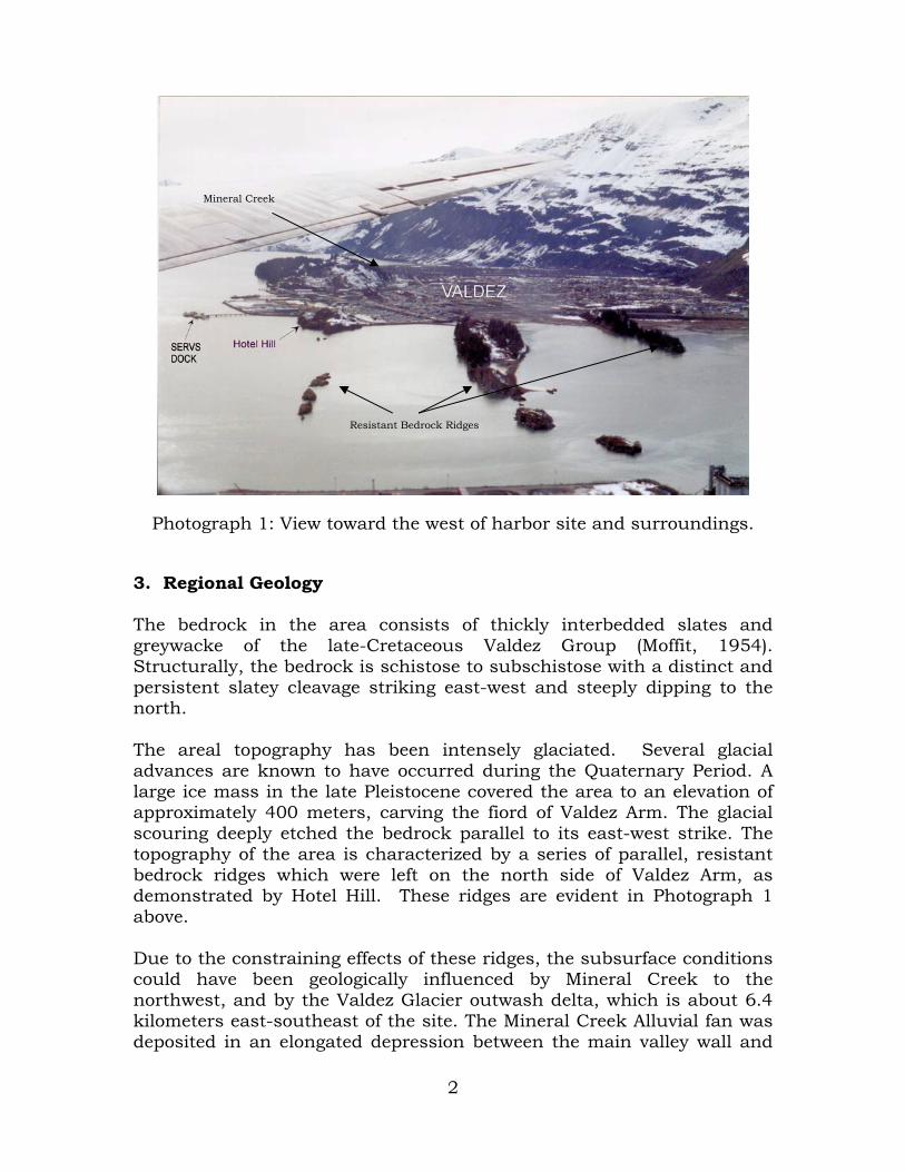
Two discrete sites make up the study area known as the East and West Sites. The East Site is immediately east of the existing SERVS Dock and just south of the large rock outcropping locally known as “Hotel Hill”. This site is the subject of the current study. The West Site, located just west of the SERVS Dock has been investigated extensively during previous studies. Photograph 1 is an oblique view of the City of Valdez, the SERVS dock, Hotel Hill, and the East Site. The project location and vicinity are shown on Figure 1. Multiple alternatives have been investigated during previous years. A 320-vessel and rubblemound design on the East Site has been selected as the National Economic Development (NED) plan. Therefore, this area is the focus of the geotechnical summary. The harbor expansion will encompass 5.7 hectares including the entrance channel and maneuvering basin. The entrance channel depth is -5.5 meters mean lower low water (MLLW) and decreases to -2.7 meters at the far west end of the basin. The south breakwater is about 445 meters in length and the east breakwater is approximately 294 meters. Dredging of the harbor to design depths will be a major undertaking as removal of large quantities will be required.
2
Photograph 1: View toward the west of harbor site and surroundings.
3. Regional Geology
The bedrock in the area consists of thickly interbedded slates and greywacke of the late-Cretaceous Valdez Group (Moffit, 1954). Structurally, the bedrock is schistose to subschistose with a distinct and persistent slatey cleavage striking east-west and steeply dipping to the north. The areal topography has been intensely glaciated. Several glacial advances are known to have occurred during the Quaternary Period. A large ice mass in the late Pleistocene covered the area to an elevation of approximately 400 meters, carving the fiord of Valdez Arm. The glacial scouring deeply etched the bedrock parallel to its east-west strike. The topography of the area is characterized by a series of parallel, resistant bedrock ridges which were left on the north side of Valdez Arm, as demonstrated by Hotel Hill. These ridges are evident in Photograph 1 above. Due to the constraining effects of these ridges, the subsurface conditions could have been geologically influenced by Mineral Creek to the northwest, and by the Valdez Glacier outwash delta, which is about 6.4 kilometers east-southeast of the site. The Mineral Creek Alluvial fan was deposited in an elongated depression between the main valley wall and
Resistant Bedrock Ridges
Mineral Creek
3
one of the discontinuous bedrock ridges that parallels the shoreline and is composed of coarse alluvial gravels underlain by cobbles and gravel in a matrix of medium to coarse sand. The Valdez Glacier outwash delta is composed of a thick section of silty sand and gravel. In the geological past, this delta likely extended to the harbor area and intermixed with deposits from the Mineral Creek fan (Golder Associates, 1993). 4. Seismic History The Valdez area is one of the most seismically active in the world. Approximately 70 earthquakes of recorded or estimated Richter magnitude 5 of greater were reported between 1898 and 1964. Five of these earthquakes generated submarine landslides. The 1964 earthquake, with a Richter magnitude of about 9 and an epicenter approximately 75 kilometers west of Valdez, triggered a massive submarine landslide across the Valdez glacier delta involving nearly 100 million cubic meters of material. The landslide and the accompanying waves it generated destroyed the old Valdez harbor facilities and near shore installations (Coulter and Migliaccio, 1966). Subsequent analysis resulted in the Office of Emergency Planning formally identifying the delta area around the Old Valdez town site as a high-risk area for soil liquefaction. The boundary of this risk area is shown on Figure 2. In an investigation of the Mineral Creek town site (essentially the new location of the City of Valdez) following the 1964 earthquake, a U.S. Army Corps of Engineers contractor stated “Although there was no direct evidence of any large submarine landslide such as occurred along the Valdez water front, a study of post-earthquake underwater contours indicates that a small slide may have occurred approximately 100 meters offshore on the extension of Beach Road (Shannon & Wilson, 1964).” Beach Road intersects the shoreline near the present day location of the Valdez Ferry Terminal (Golder Associates, 1993).
5. Field Explorations
Four field explorations have been performed within or adjacent to the East Site which can be used to provide a general subsurface characterization of the area. A detailed investigation was prepared by Golder Associates for the Alyeska Pipeline Service Company’s SERVS Dock in 1993. A geophysical subbottom reflection profiling study of the areas on both sides of the SERVS Dock was conducted for the U.S. Army Corps of Engineers – Alaska District (USACE-AD) by Tryck Nyman Hayes, Inc. using Geo-Recon International in August 2000. A shallow test pit exploration was conducted by the USACE-AD within the tidal zone east of the SERVS Dock in August 2000. Also, USACE-AD performed a detailed investigation for the West Site in 2004. Reports from these

4
explorations are on file at the USACE-AD’s Soils and Geology Section. A Test Boring and Test Pit Location Map, including locations for all exploration points for the previous investigations is enclosed as Figure 3.
5.1 Golder Associates Exploration for the SERVS Dock Golder Associates performed a subsurface exploration for the existing SERVS dock during March 1993 and issued a report of their findings and recommendations in June of the same year. The exploration consisted of drilling twelve borings, instrumenting and driving three indicator piles, completing a marine seismic survey, and conducting reconnaissance rock mapping. Laboratory testing was also performed for material classification and for measurement of engineering properties to be used for design analysis and computations.
5.2 Geo-Recon International Geophysical Investigation Geophysical methods were used to provide information on bedrock depth and profile. The work was undertaken by Geo-Recon International using a low frequency bubble pulsar to map reflected electromagnetic energy. Energy generally passes through lower density material and is reflected by higher density material.
5.3 Corps of Engineers East Site Test Pit Exploration Six test pits were excavated on May 5 and 6, 2000 to collect soil samples for both classification and chemical testing. Surface samples were also obtained for chemical testing at five other locations. All sampling was performed in intertidal areas during low tide events to maximize the exploration area as far seaward into the proposed harbor basin as possible. The results of the chemical testing have been detailed in a separate report prepared by USACE-AD’s Materials Section. The test pits were excavated with a rubber-tired Case 580 Extendahoe. Test pits were logged in accordance with ASTM D-2488, “Description and Identification of Soils (Visual – Manual Procedure)” by an engineer with USACE-AD. Generally, one sample was obtained from each test pit for soil classification testing. All test pit locations fall within the East Site. 5.3.1 Laboratory Testing of Test Pit Samples After visual classification in the field, selected soil samples were transported to the laboratory where a testing program was established to determine the physical properties of the soils encountered. The testing program established is presented below:

5
Sieve analyses were conducted and grain size distribution was determined in conformance with ASTM D-422, “Particle Size Analysis of Soils.”
Soils were classified in accordance with ASTM D-2487,
“Classification of Soils for Engineering Purposes (Unified Soil Classification System).”
5.4 Corps of Engineers West Site Test Boring Exploration The test boring exploration for the West Site was conducted from 15 June to 1 July 2004. A total of 16 test borings were drilled and range in depth from six to 30.5 meters below mudline. The borings have been designated AP-01 to AP-16. The test borings were drilled using a truck-mounted CME-85 and a track-mounted Mobile B-61. The onshore and intertidal borings were drilled with the Mobile B-61 and the offshore borings were drilled with the CME-85. The West Site intertidal area during a low tide event is shown in Photographs 2 and 3. The onshore and intertidal borings were drilled with continuous flight, hollow stem auger having an outside diameter of 203 millimeters. The offshore borings were advanced using wash-rotary drilling methods with 102-millimeter inside diameter steel casing. Denali Drilling, Inc., under contract with the USACE-AD own and operate the drilling equipment and furnished the barge used as the offshore drilling platform. Two engineers with USACE-AD supervised the 24-hour per day drilling operation and logged the test borings in accordance with ASTM D 2488, "Description and Identification of Soils (Visual - Manual Procedure)."

6
Photograph 2: Westward view intertidal area of the proposed West Site.
Photograph 3: Eastward view intertidal area of West Site. SERVS Dock in background.

7
Generally, for test borings located onshore and in the intertidal area, soil samples were procured at the surface, and at depths of 760 millimeters, 1.5 meters, and 1.5-meter intervals thereafter. Offshore, soil samples were collected at 1.5 meters below mudline, defined as the top of the soil, and at 1.5-meter intervals to the limit of exploration with the exception that sampling at 3-meter intervals was used at depth in two of the deeper test borings. Grab samples were collected at the ground surface for the onshore and intertidal borings. Thereafter, soil samples were collected using a 63.5-millimeter inside diameter, split spoon sampler driven with a 154-kilogram hammer falling 760 millimeters. The hammer was operated with an auto-hammer on the CME-85 and a cathead and rope on the Mobile B-61. The sampler was driven a maximum of 450 or 600 millimeters ahead of the auger. The number of blows required to drive each 150-millimeter increment is recorded on the exploration logs. The blow count is an indication of the relative density or consistency of the soil. A chemist with the USACE-AD scanned soil samples collected from AP-13, AP-14, and AP-15 for volatile organic compounds (VOCs) using a photo ionization detector (PID). PID results, in parts per million (PPM), are recorded on the exploration logs. Soil samples were also collected for additional chemical testing using laboratory methods. The test borings were located using standard survey techniques. DOWL Engineers, LLC, under contract with the USACE-AD, performed the survey. Horizontal coordinates are based on Alaska State Plane Zone 3, NAD83. Elevations are based on NOAA benchmark 4240 N having an elevation of 5.0932 meters above MLLW. 5.4.1 Laboratory Testing and Soil Classification A laboratory testing program was established to classify and determine the physical and engineering properties of the encountered soils. The testing program used the latest version of the following test methods: ASTM D 422, "Standard Test Method for Particle Size Analysis of Soils". ASTM D 2487, "Classification of Soils for Engineering Purposes (Unified Soil Classification System)". ASTM D 4318, “Standard Test Method for Liquid Limit, Plastic Limit, and Plasticity Index of Soils” Modified ASTM D 4767, “Standard Test Method for Consolidated-Undrained Triaxial Compression Test on Cohesive Soils”.

8
Consolidated-Drained (CD) Triaxial Compression Test (Consolidated-Quick (R) Shear). No undisturbed soil samples could be collected due to the non-cohesive and coarse-grain nature of subsurface soils. ASTM D 4767 was modified for use with cohesionless soils. The testing laboratory was directed to fabricate composite samples of low, medium, and high unit densities for triaxial testing. The tri-axial tests were then performed at confining pressures of 70, 140, and 210 kilopascals. Mohr’s circles were developed from the results to obtain strength characteristics of the soils. The results of the chemical sampling are presented separately in a chemical data report prepared by the USACE-AD Materials Section.
6. Site Conditions
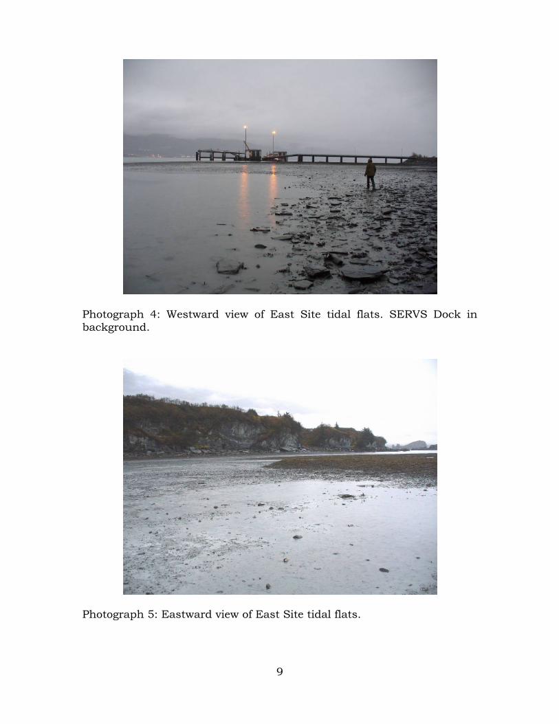
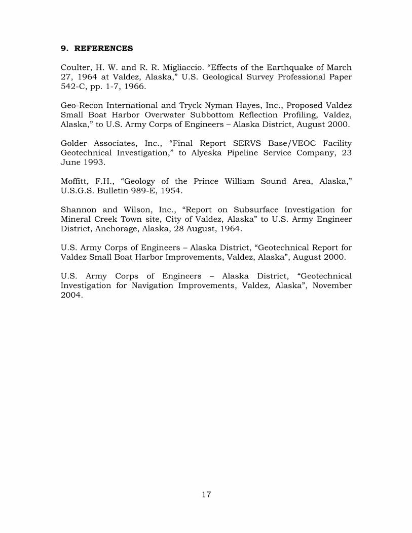
6.1 Surface 6.1.1 General The East Site is bounded by Hotel Hill to the north, The SERVS Dock to the west, and open water to the south and east. The existing mudline within the proposed harbor of the East Site generally lies between an elevation of about 2 to -2 meters MLLW. The site is relatively flat and is shown at a low tide in Photographs 4 and 5. The surface typically consists of silts, sands, and gravels with some exposed cobbles and boulders. An armored primary fiber optic cable is buried and partially buried where it crosses the tidal flats on the west side of the East Site. The partially buried cable is shown on Photograph 6. Massive rock slabs originating from Hotel Hill extend seaward from shore as shown in Photographs 7 and 8. Just exterior and south of the proposed harbor and parallel to the shore, the mudline becomes steeply inclined falling to the depths of Valdez Arm. 6.1.2 Bedrock Outcrops The bedrock near the East Site consists of metasedimentary rocks, chiefly interbedded metagraywacke and slate, grading to phyllite in places. The rock outcrops as parallel ridges, which strike east-west, parallel to the topographic grain in the region, and forming several islands in the intertidal zone. These rocks are generally tough, fresh to slightly weathered, and moderately strong. The foliation and bedding are parallel. The bedding dips steeply toward the north at all outcrops within a 1.2 kilometer radius of the site. The bedding planes are subschistose in some of the finer grained metasedimentary layers. The prominent joints are very steep and are oriented perpendicular to the bedding (Golder Associates, 1993).
9
Photograph 4: Westward view of East Site tidal flats. SERVS Dock in background.
Photograph 5: Eastward view of East Site tidal flats.

10
Photograph 6: Partially buried primary fiber optic cable.
Photograph 7: Massive rock slabs at base of Hotel Hill.

11
Photograph 8: East Site tidal flats and Hotel Hill. The south facing sides of the bedrock outcrops near the proposed site are typically steep, often vertical to overhanging in places. The rock breaks off the outcrops in large, thick, tabular slabs of riprap size, parting on the weaker bedding planes. Bedding varies from 2.5 to 130 millimeters thick. The widths of the slabs are controlled by the joints. Discontinuities are rough to very rough with mostly planar form. Quartz fills some of the discontinuities. Joints are usually closed and well spaced (Golder Associates, 1993). 6.1.3 Tides Tidal data for the Valdez boat harbor, referenced to MLLW, is provided below in TABLE 1.
TABLE 1: Tidal data (MLLW), Valdez, Alaska
Tide Elevation (m)
Extreme High Tide 4.7 Mean Higher High Water 3.7 Mean High Water 3.3 Mean Tide 1.9 Mean Low Water 0.4 Mean Lower Low Water (datum) 0 Lowest Estimated Tide -1.1 Lowest Observed Water Level -1.4

12
6.2 Subsurface 6.2.1 Soils Golder Associates’ investigation conducted in 1993 for the SERVS Dock provides detailed subsurface information for that facility to significant depths. They characterize the offshore subsurface profile out to approximately the -10 meters MLLW bathymetric contour as comprised of “shelf” deposits of sediments overlying an irregular bedrock contact. The sediments typically consist of loose to compact sandy gravel with trace to little silt, and increasing percentages of cobbles and boulders (in the lower reaches explored by Golder Associates) overlying compact sandy silt with trace gravel. Two generalized cross-sections from the study based on test borings and geophysical data are presented in Figure 4. The USACE-AD test pit exploration at the East Site generally indicates surficial layers of silty SAND with gravel (SM) and poorly graded SAND with gravel (SP) to poorly or well-graded GRAVEL with sand (GP to GW). The test pits all encountered water at depths of 0.2 to 0.3 meters below the ground surface that freely flowed through the coarser zones, creating caving conditions and limiting the depth of the excavations to about 1.5 meters. Cobbles up to 0.15 meters were generally observed in all test pit excavations, with the frequency and size of cobbles increasing as the distance to Hotel Hill decreased. A large rock slab having dimensions of about 2 x 1.5 x 0.4 meters was encountered about 30 meters away from the face of Hotel Hill in Test Pit 2. It is suspected that the likelihood of encountering these large slabs and boulder-size rocks increases with proximity to Hotel Hill. The USACE-AD test boring exploration at the West Site indicates the subsurface soils are predominately composed of gray, wet, poorly and well-graded gravel and sand with silt, silty gravel, and silty sand (GP-GM, GW-GM, SP-SM, SW-SM, GM, SM). Cobbles are suspected in some borings as indicated by blow counts. Where suspected, they are annotated in the exploration logs as part of the soil classification. Blow counts indicate the soils are predominately medium dense to dense. A typical sample of the subsurface soils is shown in Photograph 9 below. 6.2.2 Bedrock In general, the profiles and contour maps from the Geo-Recon geophysical survey indicate a bench-like bedrock surface that slopes downward towards shore (to the north) while seaward (south) the surface terminates abruptly in “cliff-like” structure(s), emerging as a flatter surface in the deeper water. Above the bedrock is a sloping overburden

13
interface that generally decreases in depth or becomes shallower towards shore. Seaward the interface appears to terminate where the bedrock grade breaks to deeper water (Geo-Recon International, 2000). From the Geo-Recon report, Suspected Bedrock Contours, Three Dimensional Suspected Bedrock Surface, and two generalized profile cross-sections are enclosed as Figures 5 through 8, respectively.
Photograph 9: Typical soil sample from West Site. Sample collected from AP-11.
7. Discussion and Analysis
This discussion is based upon information procured during the previous explorations discussed above. Based upon the findings of these sources, four construction concerns exist:
foundation conditions for breakwaters, the dredgibility of the subsurface materials within the proposed
East Site, the stability of excavated side slopes, and the stability of existing submarine slopes after construction.
These items are discussed below:

14
7.1 Foundation Conditions The foundation materials above bedrock and beneath the proposed breakwater locations are composed primarily of coarse-grained soils with a 3 to 4-meter layer of silt close to the bedrock surface. Test boring logs from an investigation of the SERVS Dock indicate these soils tend to become looser as distance increases from shore. These soils are suitable materials for support of the breakwater, and the majority of foundation settlement should occur during construction. Slope stability for breakwaters placed close to the edge of the southern steeply inclined slope is discussed below.
7.2 Dredging Characteristics Based on the geophysical report by Geo-Recon International and existing subsurface information, it appears bedrock will not be encountered within dredging limits for the large majority of the harbor. However, the bedrock surface needs to be better defined within the dredging area near Hotel Hill. In addition, boulders and massive rock slabs are likely to be encountered near Hotel Hill. It is expected that their frequency and size will decrease seaward.
7.3 Excavation Slope Stability Excavated slopes in the sand and gravel soil will be influenced by tidal fluctuation and wave erosion. Rather steep slopes may appear stable at the time of excavation, but will erode over time to a less steep slope. A maximum slope of about 3H:1V is estimated for these materials based on experience and observations of existing slopes at the site.
7.4 Existing Marine Slope Stability at Breakwaters As discussed previously, the bottom profile inclines steeply into deeper water immediately south of the proposed breakwater locations of both the East and West sites raising concerns for slope stability once breakwaters are constructed. A preliminary analysis using UTEXAS4 was performed by USACE-AD during the 2000 investigation. The analysis concluded that loadings from the proposed breakwater alignments have no contributory impact on the slope’s stability under static conditions. Material properties were estimated based upon the information collected from the test pits and more particularly from the engineering properties tabulated in Golder Associates’ 1993 geotechnical report for the SERVS Dock. This preliminary analysis was further refined as a result of the 2004 investigation listed below.

15
Stability analyses were again performed during the 2004 investigation by the Corps when more detailed subsurface information was obtained during the exploration of the West Site. The UTEXAS4 program, implementing both the Spencer method and the Lowe and Karafiath method for determining slope stability under static conditions, were used in the analyses. Stability was analyzed at both high and low tide elevations. Both methods found the slope and breakwater were stable with minimum factor of safeties of 1.5 or greater. These analyses placed the toe of the breakwater approximately 10 meters from the interpreted slope break. Similar conditions are expected at the East Site.
In light of the known occurrences of soil liquefaction and sub-aqueous landslides near the project area during previous seismic events, an analysis was performed during the 2004 investigation to determine liquefaction potential of the subsurface soils. The liquefaction analysis indicated that the deposit is potentially liquefiable as did Golder Associates analyses. However, a pseudo-static seismic analysis of the slope using the UTEXAS4 program showed the slope to be stable. It should be realized that no documented sub-aqueous slides due to liquefaction were identified within the proposed project area as a result of the Great Alaska Earthquake of 1964. The apparent nonoccurrence of liquefaction in 1964 is likely attributable to the high permeability and particle angularity of the deposits.
8. Conclusions
The expansion of the Valdez small boat harbor at the East Site can be accomplished as planned based upon the information available at this time. However, more detailed subsurface information is needed along the southern sides of the planned basin and within the dredging area to sufficiently characterize the subsurface conditions. It is recommended that additional test boring and pits be performed within the harbor basin and along breakwater alignments. The explorations would identify the approximate top of bedrock, define the characteristics of the materials to be dredged, and provide site specific engineering properties of the subsurface soils. Enclosures: Figure 1 – Project Location and Vicinity Map Figure 2 – High-Risk for Liquefaction Area Figure 3 – Test Boring and Test Pit Location Map

16
Figure 4 – Generalized Cross-Sections Figure 5 – Suspected Bedrock Contours Figure 6 – Suspected Bedrock Surface Figure 7 – Profile Line H-3 Figure 8 – Profile Line H-4 Appendix A – Test Boring and Test Pit Logs
17
9. REFERENCES Coulter, H. W. and R. R. Migliaccio. “Effects of the Earthquake of March 27, 1964 at Valdez, Alaska,” U.S. Geological Survey Professional Paper 542-C, pp. 1-7, 1966. Geo-Recon International and Tryck Nyman Hayes, Inc., Proposed Valdez Small Boat Harbor Overwater Subbottom Reflection Profiling, Valdez, Alaska,” to U.S. Army Corps of Engineers – Alaska District, August 2000. Golder Associates, Inc., “Final Report SERVS Base/VEOC Facility Geotechnical Investigation,” to Alyeska Pipeline Service Company, 23 June 1993. Moffitt, F.H., “Geology of the Prince William Sound Area, Alaska,” U.S.G.S. Bulletin 989-E, 1954. Shannon and Wilson, Inc., “Report on Subsurface Investigation for Mineral Creek Town site, City of Valdez, Alaska” to U.S. Army Engineer District, Anchorage, Alaska, 28 August, 1964. U.S. Army Corps of Engineers – Alaska District, “Geotechnical Report for Valdez Small Boat Harbor Improvements, Valdez, Alaska”, August 2000. U.S. Army Corps of Engineers – Alaska District, “Geotechnical Investigation for Navigation Improvements, Valdez, Alaska”, November 2004.

A
Appendix A


![Valdez daily prospector. [Valdez, Alaska]. 1916-12-28 [p 4]](https://img.pdfslide.us/doc/110x75/615ac2044448c27f6d4bb2e7/valdez-daily-prospector-valdez-alaska-1916-12-28-p-4.jpg)