Embed Size (px)
Citation preview
GEOTECHNICAL SUBSURFACE EXPLORATION GRIC CENTRAL SUBDIVISION
SEC CHOLLA ROAD AND SEED FARM ROAD SCATON, ARIZONA
Prepared for: GRIC Property and Supply
312 W. Casa Blanca Rd., Post Box 97 Sacaton, AZ 84257
Prepared by:
Alpha Geotechnical & Materials, Inc. 2504 W. Southern Avenue
Tempe, Arizona 85282
Expires 3/31/2014
Job # 12-G-2697
August 7, 2012 Alpha Project #12-G-2697 GRIC Property and Supply 312 W. Casa Blanca Rd., Post Office Box 97 Sacaton, AZ 84257 Attention: Ms. Cynthia Gerard RE: Geotechnical Subsurface Exploration
GRIC Central Housing Subdivision SEC Cholla Road and Seed Farm Road Sacaton, Arizona
Dear Ms. Gerard: In accordance with your request and authorization, Alpha Geotechnical & Materials, Inc. (Alpha) has performed a geotechnical subsurface exploration for the GRIC Central Housing Subdivision residential development located on the southeastern corner of Cholla Road and Seed Farm Road in Sacaton, Arizona. The purpose of this report is to provide recommendations relative to the geotechnical aspects of design and construction of the project. Based on our findings, the site is considered suitable for the proposed construction, provided foundation systems are properly designed, specified site grading recommendations are used, and foundation bearing soils are not exposed to moisture infiltration or moisture content fluctuation. Specific recommendations regarding the geotechnical aspects of project design and construction are presented in the following report. The recommendations contained within this report are dependent on the provisions provided in the Limitations and Recommended Additional Services sections of this report. We appreciate the opportunity to provide our services for this project. If you have questions regarding this report or if we may be of further assistance, please contact the undersigned. Sincerely, ALPHA GEOTECHNICAL & MATERIALS, INC. Scott R. Smith, P.E. Senior Geotechnical Engineer
TABLE OF CONTENTS
1. EXECUTIVE SUMMARY .................................................................................................1
2. INTRODUCTION ...............................................................................................................3 2.1. General ...................................................................................................................3 2.2. Proposed Project ...................................................................................................3
3. FIELD EXPLORATION ....................................................................................................4
4. LABORATORY TESTING ...............................................................................................4
5. GEOLOGY CONDITIONS ...............................................................................................5 5.1. Regional Geology..................................................................................................5
6. GENERAL SITE CONDITIONS......................................................................................5 6.1. Surface Conditions................................................................................................5 6.2. Subsurface Conditions .........................................................................................6 6.3. Groundwater Conditions ......................................................................................6 6.4. Geologic Hazards..................................................................................................7
6.4.1. Liquefaction Potential ...............................................................................7 6.4.2. Collapsible Soils ........................................................................................7
6.5. Seismic Considerations........................................................................................7 6.6. Land Subsidence and Earth Fissures ................................................................8
7. ENGINEERING ANALYSES AND RECOMMENDATIONS ......................................8 7.1. Earthwork................................................................................................................8
7.1.1. Post-Tension Slabs ...................................................................................8 7.1.2. Exterior Slabs.............................................................................................9 7.1.3. Conventional Spread Footings (Secondary Structures) .....................9 7.1.4. Aggregate Base Course .........................................................................10 7.1.5. Engineered Fill .........................................................................................10 7.1.6. Temporary Excavations..........................................................................12 7.1.7. Trench Backfill .........................................................................................14 7.1.8. Permanent Excavations and Slopes ....................................................15
7.2. Shallow Foundations ..........................................................................................16 7.2.1. Shallow Spread Footings .......................................................................16
7.2.1.1. Allowable Bearing Pressure ..........................................16 7.2.1.2. Estimated Settlements ...................................................17
7.2.2. Floor Slab .................................................................................................17 7.2.3. Structural slabs (post-tensioned or reinforced mat-type slabs) .......17 7.2.4. Resistance to Lateral Loads ..................................................................18 7.2.5. Retaining Walls........................................................................................19
7.2.5.1. Lateral Earth Pressures .................................................19 7.2.5.2. Wall Drainage ..................................................................19 7.2.5.3. Backfill Placement ...........................................................20
7.3. Moisture Protection .............................................................................................20
7.4. Corrosion Potential..............................................................................................21 7.4.1. Sulfate and Chloride Content ................................................................21 7.4.2. Aggregate Base Course .........................................................................22
8. CLOSURE ........................................................................................................................23 8.1. Limitations ............................................................................................................23 8.2. Recommended Additional Services .................................................................24
APPENDIX A – Sample Location Plan APPENDIX B – Soil Test Logs APPENDIX C – Laboratory Test
Geotechnical Subsurface Investigation Alpha Project 12-G-2697 GRIC Central Subdivision Sacaton, Arizona Page 1 of 25
1. EXECUTIVE SUMMARY
August 7 2012 Alpha Project #12-G-2697 GRIC Property and Supply 312 W. Casa Blanca Road, Post Office Box 97 Sacaton, AZ 84257 Attention: Ms. Cynthia Gerard RE: Geotechnical Subsurface Investigation
GRIC Central Subdivision SEC Cholla Road and Seed Farm Road Sacaton, Arizona
The purpose of this exploration was to evaluate the general surface and subsurface conditions at the referenced site, and to present geotechnical design recommendations for foundations, slab-on-grade, and on-site pavements for the proposed development. Geotechnical Site Reconnaissance The project is bounded to the north by Seed Farm Road, to the west by Cholla Road, to the east by residential single family subdivisions, and south by vacant land. Both Seed Farm Road and Cholla Road were paved with asphaltic concrete as were the interior streets (Wipsmal Street, Chiadag Street, Nakshel Street, Toha Street, and Whog Street). Site topography was relatively flat with 124 existing single level homes across the site. At the time of our study, the majority of lots had none to a light growth of shrubs and trees present. Site Soils The naturally occurring coarse grained site surface and subsurface soils encountered during our exploration consisted primarily of clayey sand (SC) with lesser amounts of silty sand (SM) and poorly graded sand (SP). The relative densities of these soils ranged from loose to medium dense. The soils sampled during our exploration had low expansive characteristics. See attached report for details. Weak carbonate cementation was found several of the soil test borings. No bedrock was encountered during our field investigation. Project Description The proposed project will include a replacement of the existing housing within the subdivision over several years. The Central Housing Subdivision (AZ 15-15, AZ 15-20, AZ 15-24, and AZ 15-30) is approximately 41 acres in area located at the southeast corner of Cholla Road and Seed Farm Road in Sacaton, GRIC, Arizona. All of the homes will be single level slab on grade. It is anticipated that the proposed residential buildings construction will be either wood frame or masonry block walls. We have not been provided with structural loads. However, based on our previous experience with similar structures, we estimate the maximum column and wall loads for the structures will be about 40 kips and 3 KLF, respectively. It is understood that the existing roadways and utilities are planned to remain in service.
Geotechnical Subsurface Investigation Alpha Project 12-G-2697 GRIC Central Subdivision Sacaton, Arizona Page 2 of 25 Site Drainage Positive drainage is essential to the successful performance of any foundation or slab-on-grade. Good surface and subsurface drainage should be established during and after construction to prevent the soils below or adjacent to the building areas from becoming wet. Desert-type landscaping is advisable near the building and pavement areas. Plants, which require more water, should be located and drained away from the structural and pavement areas. Foundations Post-tensioned slabs and/or conventional footings bearing on properly compacted engineered fills may be used to support the structures. We anticipate that total and differential settlements for foundations designed in accordance with the recommendations provided in the attached report, will be within generally acceptable tolerance as presented in the attached report. Additional foundation movements could occur if water from any source infiltrates the foundation soils.
Land Subsidence and Earth Fissures The project site is located approximately ten (10) miles east of an area of documented earthen fissures in the Signal Butte area and in an area with a measured land subsidence of between zero and one foot (Land Subsidence and Earth Fissures in Alluvial Deposits in Phoenix area, Arizona by H.H. Schumann, 1974, and http://azmap.org/fissures). Conclusion Based on our findings, the site is considered suitable for the proposed residential development, imposing relatively light foundation loads provided slab/foundation systems are properly designed, specified compaction for fill material is used, and foundation bearing soils are not exposed to moisture infiltration or moisture content fluctuation.
Should you have any questions concerning the contents of this report or any other matter, please do not hesitate to contact the undersigned at (602) 453-3265.
Respectfully submitted,
Alpha Geotechnical & Materials, Inc. Scott R. Smith, P.E. (expires 3/31/2014)
Senior Geotechnical Engineer
Geotechnical Subsurface Investigation Alpha Project 12-G-2697 GRIC Central Subdivision Sacaton, Arizona Page 3 of 25
2. INTRODUCTION
2.1. General
The purpose of this geotechnical exploration was to evaluate the general surface and
subsurface conditions at the referenced site, and to present recommendations related to
geotechnical aspects of design and construction of the project for foundations. Results
of our field/laboratory testing are also presented within this report. Our scope of services
was in general accordance with our proposal 12-G-2697, dated June 27, 2012. This
geotechnical report is based on available project information and the site plan provided
by the client and our experience with similar construction and soil conditions.
Our study included a site reconnaissance, subsurface exploration, soil sampling, field
and laboratory testing, engineering analyses, and preparation of this report. This report
presents recommendations for design of suitable foundation types, site grading and
structural fill placement, moisture protection, and construction considerations. The
recommendations contained in this report are subject to the limitations presented
herein. Attention is directed to the “Limitations” section of this report.
2.2. Proposed Project
The proposed project will include a replacement of the existing housing within the
subdivision over several years. The Central Housing Subdivision (AZ 15-15, AZ 15-20,
AZ 15-24, and AZ 15-30) is approximately 41 acres in area located at the southeast
corner of Cholla Road and Seed Farm Road in Sacaton, GRIC, Arizona. All of the
homes will be single level slab on grade. It is anticipated that the proposed residential
buildings construction will be either wood frame or masonry block walls. We have not
been provided with structural loads. However, based on our previous experience with
similar structures, we estimate the maximum column and wall loads for the structures
Geotechnical Subsurface Investigation Alpha Project 12-G-2697 GRIC Central Subdivision Sacaton, Arizona Page 4 of 25
will be about 40 kips and 3 KLF, respectively. It is understood that the existing
roadways and utilities are planned to remain in service.
3. FIELD EXPLORATION
Eight soil test borings were advanced at the subject site to an approximate depth of
fifteen (15) feet below existing ground level with a CME 55 power drill rig. The soil test
borings were advanced using 8-inch hollow stem augers to develop information relative
to foundation and pavement design recommendations. The borings were located in the
field at the approximate locations shown on the sample location plan included in the
Appendix A of this report. Prior to the start of drilling, the Arizona Blue Stake Center
was contacted to locate existing utilities at the boring locations. Upon completion of the
borings, the boreholes were backfilled with excavated materials.
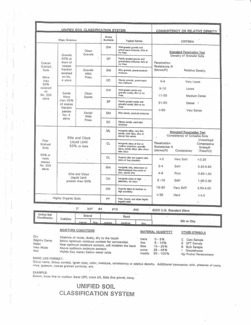
Soil classifications made during our field exploration from excavated soil samples were
confirmed in the laboratory after further examination. The site soils were classified in
accordance with the Unified Soil Classification System presented, along with the soil
test logs, in Appendix B. Sample classifications and other related information are
recorded on the soil boring logs which are presented in Appendix B.
4. LABORATORY TESTING
Selected soil samples from the borings were tested in the laboratory for classification
purposes and to evaluate their engineering properties. The laboratory tests included:
Gradation; Atterberg limits; Moisture content; One-dimensional consolidation; Undisturbed ring density; Sulfate content;
Geotechnical Subsurface Investigation Alpha Project 12-G-2697 GRIC Central Subdivision Sacaton, Arizona Page 5 of 25
Chloride content; Soluble salts; Expansion index. A brief description of each test preformed on the soil samples and the results are
presented in Appendix C.
5. GEOLOGY CONDITIONS
5.1. Regional Geology
The southwest region of Arizona is referred to as the Basin and Range Geologic
Province. This province consists primarily of a low dry desert environment with a
mixture of long faults, fractured rock and wide alluvial basins. The mountain ranges
within the province consist of Precambrian plutonic, volcanic and metamorphic rock.
6. GENERAL SITE CONDITIONS
6.1. Surface Conditions
The project is bounded to the north by Seed Farm Road, to the west by Cholla Road, to
the east by residential single family subdivisions, and south by vacant land. Both Seed
Farm Road and Cholla Road were paved with asphaltic concrete as were the interior
streets (Wipsmal Street, Chiadag Street, Nakshel Street, Toha Street, and Whog
Street). Site topography was relatively flat with 124 existing single level homes across
the site. At the time of our study, the majority of lots had none to a light growth of shrubs
and trees present.
The existing asphaltic concrete streets pavements were observed during the field
investigation. Wipsmal Street had extensive cracking of the asphaltic concrete surface
with cracking at an approximately 6 inch spacing with one inch wide transverse cracking
Geotechnical Subsurface Investigation Alpha Project 12-G-2697 GRIC Central Subdivision Sacaton, Arizona Page 6 of 25
approximately every 10 feet. Most of a chip seal surfacing had worn off of the pavement
surface. Chiadag Street had extensive cracking of the asphaltic concrete surface with
cracking at an approximately 6 inch spacing with one inch wide transverse cracking
approximately every 10 feet. The pavement surface was raveled and there were some
recent patches in the wider cracks. Nakshel Street had large block cracking at
approximate 6 foot spacing with cracks of one to one and one half inch width. Toha
Street had extensive cracking of the asphaltic concrete surface with cracking at
approximate 6 inch spacing. Whog Street had block cracking at 6 to 8 feet spacing with
areas of eight inch spacing between cracks adjacent to the some of the larger block
cracks.
6.2. Subsurface Conditions
The naturally occurring coarse grained site surface and subsurface soils encountered
during our exploration consisted primarily of clayey sand (SC) with lesser amounts of
silty sand (SM) and poorly graded sand (SP). The relative densities of these soils
ranged from loose to medium dense. The soils sampled during our exploration had low
expansive characteristics. Weak carbonate cementation was found several of the soil
test borings. No bedrock was encountered during our field investigation.
6.3. Groundwater Conditions
At the time of our field investigation, free groundwater was not encountered in our
explorations. It should be noted that groundwater and soil moisture conditions within
the area will vary depending on rainfall, irrigation practices, and/or runoff conditions not
apparent at the time of our field investigation.
Geotechnical Subsurface Investigation Alpha Project 12-G-2697 GRIC Central Subdivision Sacaton, Arizona Page 7 of 25
6.4. Geologic Hazards
6.4.1. Liquefaction Potential
Based on the type and densities of the native site soils encountered during this
investigation and groundwater not being encountered at depth explored, the preliminary
potential for soil liquefaction is considered to be negligible.
6.4.2. Collapsible Soils
Collapsible soils are soils with the potential for a decrease in volume with an increase of
external load or moisture. These soils are typically found in areas of alluvial deports with
semi-arid to arid climates. Based on the information collected during our field
investigation and subsequent laboratory testing, we anticipate collapse-susceptible soils
will be encountered during construction. Based on ASTM D 5333, the collapse potential
of the undisturbed ring samples collected during our field investigation indicated a
moderate to high collapse potential. The potential for damage due to the collapse of the
site soil is considered low provided that the overexcavation and recompaction measures
for the sub-grade improvements are implemented in accordance with the
recommendations presented in section 7 of this report.
6.5. Seismic Considerations
The project site is located in south-central Arizona which is an area of low seismic
activity. The following values were developed using the 2006 International Building
Code (IBC) and are based on knowledge of local geologic conditions, and subsurface
soils encountered during our investigation. A 100 foot soil test boring was not advanced
during our field investigation and, therefore, our recommendations are based on our
knowledge of subsurface conditions and our experience in the vicinity of the project site.
A site class D (stiff soil profile 1.60 and 2.40) may be used for design.
Geotechnical Subsurface Investigation Alpha Project 12-G-2697 GRIC Central Subdivision Sacaton, Arizona Page 8 of 25
Central Latitude………………………………………...33.071543˚
Central Longitude…………………….………………-111.744733˚
Ss Spectral Acceleration for Short Period….……………0.202g
S1 Spectral Acceleration for a 1-Second Period.............0.101g
Fa Site Coefficient for Short Period………………………….1.6
Fv Site Coefficient for a 1-Second Period…………………..2.4
6.6. Land Subsidence and Earth Fissures
The project site is located approximately ten (10) miles east of an area of documented
earthen fissures in the Signal Butte area and in an area with a measured land
subsidence of between zero and one foot (Land Subsidence and Earth Fissures in
Alluvial Deposits in Phoenix area, Arizona by H.H. Schumann, 1974, and
http://azmap.org/fissures).
7. ENGINEERING ANALYSES AND RECOMMENDATIONS
7.1. Earthwork
7.1.1. Post-Tension Slabs
All existing structural remnants, fill, pavement, topsoil, vegetation and organic soils
should be removed from below the structure areas. The on-site soils are acceptable for
use as engineered fill. The site soil should be over-excavated to a depth of two feet
below the existing grade or proposed bottom of footing elevation, whichever elevation is
lower. The exposed subsurface soils should then be scarified to a depth of 8-inches:
moisture conditioned to within 2 percent of optimum moisture content and compacted to
a minimum of 95% of maximum dry density. The excavated material should then be
moisture conditioned to within 2 percent of optimum moisture content and compacted to
Geotechnical Subsurface Investigation Alpha Project 12-G-2697 GRIC Central Subdivision Sacaton, Arizona Page 9 of 25
a minimum of 95% of maximum dry density as engineered fill. Optimum moisture
content and maximum dry density should be determined by American Society for
Testing and Materials (ASTM) D 698. It is our recommendation that the entire foot print
plus a 5-foot blow out be prepared as described above.
7.1.2. Exterior Slabs
All existing structural remnants, fill, pavement, topsoil, vegetation and organic soils
should be removed from below the exterior slab location. The soils below exterior slabs
are collapsible and have the potential for post-construction movement. To decrease the
potential for post-construction movement the site soils should be scarified to a depth of
twelve inches; moisture conditioned to within 2 percent of optimum moisture content
and compacted to a minimum of 95% of maximum dry density.
7.1.3. Conventional Spread Footings (Secondary Structures)
(If secondary only) All existing structural remnants, fill, pavement, topsoil, vegetation
and organic soils should be removed from below the structure areas. Conventional
foundations are recommended to support secondary structures (e.g. site walls). The soil
below the footing elevation should be removed to a depth of one foot. The exposed
subsurface soils should then be scarified to a depth of 8-inches: moisture conditioned to
within 2 percent of optimum moisture compacted to a minimum of 95 percent of
maximum dry density. Optimum moisture content and maximum dry density should be
determined by ASTM D 698. The over excavation of site soils should be extend laterally
for a minimum distance of 3-feet beyond the perimeter of secondary structures.
Geotechnical Subsurface Investigation Alpha Project 12-G-2697 GRIC Central Subdivision Sacaton, Arizona Page 10 of 25
7.1.4. Aggregate Base Course
A layer of clean granular material, a minimum of 4 inches thick, should be placed
beneath concrete slabs to serve as a leveling base, and to aid in concrete curing. The
material should conform to the gradation requirements set by the local governing and/or
MAG section 702 specifications for Aggregate Base Course (ABC). The use of moisture
barriers beneath the floor slabs may be helpful, but is not a geotechnical requirement;
however, the architect or the slab designer should evaluate their need.
All aggregate base should be placed in lifts not thicker than eight inches and compacted
to a minimum of 98 percent of maximum dry density as determined by American Society
for Testing and Materials (ASTM) Test Method D 698 or as specified by local
specifications. The moisture content during compaction should be maintained within
two percent of optimum moisture content.
7.1.5. Engineered Fill
Engineered fill materials should be composed of on-site soils or imported soils,
generally meeting the requirements for imported soils presented below. All engineered
fills should be compacted as noted.
1. Native granular soils or imported soils with low expansive potentials could be used as fill material for the following:
o general site grading o foundation areas o interior floor slab areas
o exterior slab areas o foundation backfill
2. Select granular materials should be used as backfill behind walls which retain earth. 3. Engineered fill should conform to the following:
Geotechnical Subsurface Investigation Alpha Project 12-G-2697 GRIC Central Subdivision Sacaton, Arizona Page 11 of 25
Percent finer by weight Gradation (ASTM C136) 3"..........................................................................................................100 No. 200 Sieve ............................................................................. 50 (max) Expansion Index (ASTM D4829) Maximum expansive index.....................................................................20
Corrosion Potential (PPM) Sulfate Content (ARIZ 733).................................................... 1,000(max)*
Chloride Content (ARIZ 736)……………………………………….500(max)* *Native site soils generally have an elevated level of sulfates and chlorides, if used within building pad fill foundations and slabs on grade need to be designed for elevated levels of concrete and reinforcement corrosion. Soil imported to the site from outside its boundaries needs to conform to the maximum allowable sulfate and chloride contents. 4. Aggregate base should conform to MAG and/or local governing specifications (or
applicable local standards)
5. The following are intended to guide in establishing adequate support for the conventional foundation elements:
o Any natural washes, depressions or new excavations which are to be
filled, should be widened as necessary to accommodate compaction
equipment and provide a level base for placing fill.
o Any engineered fill (backfill) materials placed beneath the foundations
should meet the requirements for Engineered Fill Materials.
o All footing excavations should be relatively level and free of loose or
disturbed material and inspected by a qualified representative of the
Geotechnical Engineer.
6. All fill soils to be used beneath the foundations; slabs and pavements should be approved by the Geotechnical Engineer. Fill should be placed in eight inch loose lifts and should extend beyond the edge of the structure for a minimum distance of five feet. Fill should be compacted as recommended in the following table.
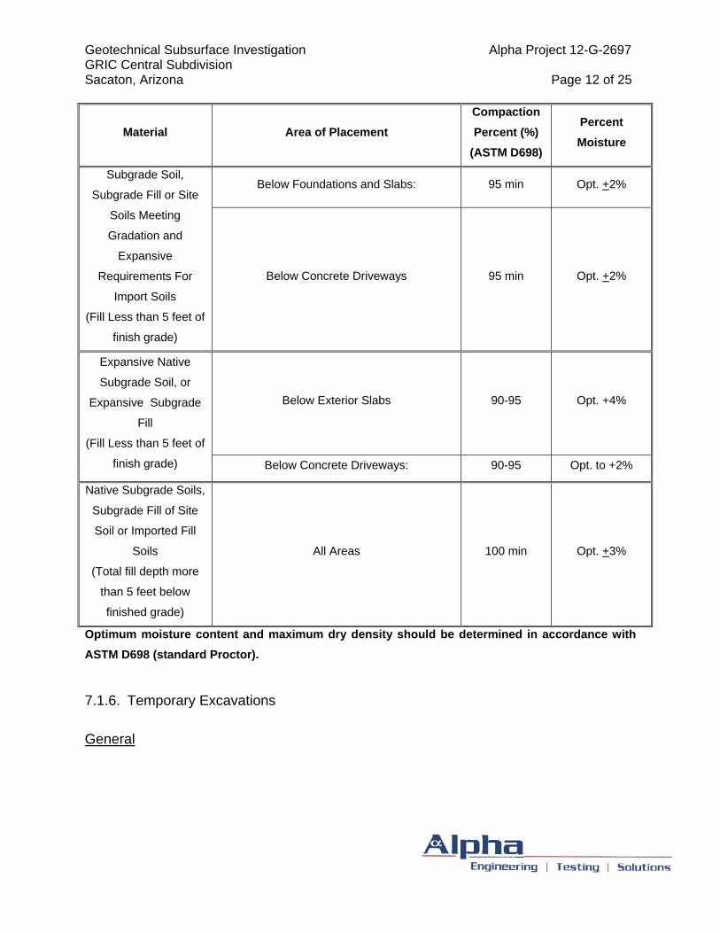
Geotechnical Subsurface Investigation Alpha Project 12-G-2697 GRIC Central Subdivision Sacaton, Arizona Page 12 of 25
Material Area of Placement
Compaction
Percent (%)
(ASTM D698)
Percent
Moisture
Below Foundations and Slabs: 95 min Opt. +2% Subgrade Soil,
Subgrade Fill or Site
Soils Meeting
Gradation and
Expansive
Requirements For
Import Soils
(Fill Less than 5 feet of
finish grade)
Below Concrete Driveways 95 min Opt. +2%
Below Exterior Slabs 90-95 Opt. +4%
Expansive Native
Subgrade Soil, or
Expansive Subgrade
Fill
(Fill Less than 5 feet of
finish grade) Below Concrete Driveways: 90-95 Opt. to +2%
Native Subgrade Soils,
Subgrade Fill of Site
Soil or Imported Fill
Soils
(Total fill depth more
than 5 feet below
finished grade)
All Areas 100 min Opt. +3%
Optimum moisture content and maximum dry density should be determined in accordance with
ASTM D698 (standard Proctor).
7.1.6. Temporary Excavations
General
Geotechnical Subsurface Investigation Alpha Project 12-G-2697 GRIC Central Subdivision Sacaton, Arizona Page 13 of 25
All excavations must comply with applicable local, state, and federal safety regulations
including the current Occupational Safety and Health Administration (OSHA) Excavation
and Trench Safety Standards. Construction site safety generally is solely the
responsibility of the Contractor, who shall also be solely responsible for the means,
methods, and sequencing of construction operations. We are providing the information
below strictly as a service to our client. Under no circumstances should the information
be interpreted to mean that Alpha is assuming responsibility for construction site safety
or the Contractor’s activities; such responsibility is not being implied and should not be
inferred.
Excavations and Slopes
The Contractor should be aware that slope height, slope inclination, or excavation
depths (including utility trench excavations) should in no case exceed those specified in
local, state, and/or federal safety regulations (e.g., OSHA Health and Safety Standards
for Excavations, 29 CFR Part 1926, or successor regulations). Such regulations are
strictly enforced and, if they are not followed, the Owner, Contractor, and/or earthwork
and utility subcontractors could be liable for substantial penalties.
Near-surface soils encountered during our field investigation consisted predominantly of
clayey sands with layers of poorly graded sand and silty sand. In our opinion, these
soils would be considered a Type C soil when applying OSHA regulations. For this soils
type OSHA recommends a maximum slope inclination of 11/2(h):1(v) or flatter for
excavations 20 feet or less in depth. Steeper cut slopes may be utilized for excavations
less than 5 feet deep depending on the strength, moisture content, and homogeneity of
the soils as observed in the field. Flatter slopes and/or trench shields may be required if
loose, cohesionless soils and/or water are encountered along the slope face.
Construction Considerations
Geotechnical Subsurface Investigation Alpha Project 12-G-2697 GRIC Central Subdivision Sacaton, Arizona Page 14 of 25
Heavy construction equipment, building materials, excavated soil, and vehicular traffic
should not be allowed within one-third the slope height from the top of any excavation.
Where the stability of adjoining buildings, walls, or other structures is endangered by
excavation operations, support systems such as shoring, bracing, or underpinning may
be required to provide structural stability and to protect personnel working within the
excavation. Shoring, bracing, or underpinning required for the project (if any) should be
designed by a professional engineer registered in the State of Arizona.
During wet weather, earthen berms or other methods should be used to prevent runoff
water from entering all excavations. All runoff water should be collected and disposed
of outside the construction limits.
7.1.7. Trench Backfill
Materials
Pipe zone backfill (i.e., material beneath and in the immediate vicinity of the pipe)
should consist of soil with a maximum particle size less than one inch. Trench zone
backfill (i.e., material placed between the pipe zone backfill and finished subgrade) may
consist of soil that meets the requirements for structural fill provided above. Also, to
reduce potential for moisture migration through trench backfill, refer to section 7.3.
If import material is used for pipe or trench zone backfill, we recommend it consist of
fine-grained sand. In general, poorly graded coarse-grained sand and gravel should not
be used for pipe or trench zone backfill due to the potential for soil migration into the
relatively large void spaces present in this type of material and water seepage along
trenches backfilled with coarse-grained sand and/or gravel.
Geotechnical Subsurface Investigation Alpha Project 12-G-2697 GRIC Central Subdivision Sacaton, Arizona Page 15 of 25
Recommendations provided above for pipe zone backfill are minimum requirements
only. More stringent material specifications may be required to fulfill local codes and/or
bedding requirements for specific types of pipes. We recommend the project Civil
Engineer develop these material specifications based on planned pipe types, bedding
conditions, and other factors beyond the scope of this study.
Compaction Criteria
Backfill of trenches should utilize non-expansive (preferably granular) soils, in order to
aid compaction and reduce potential differential settlement problems. Backfilling of utility
trenches should be in 6 to 8-inch maximum loose lifts, and compacted to a minimum of
90%, and 95% of ASTM D-698 (standard Proctor), in non-structural areas and
structurally loaded areas, respectively. Please note that the local governing agency
specifications may surpass these trench backfill requirements. Water settling of granular
backfill soils should be done in strict accordance with the local governing agency and/or
MAG Section 601.4. Jetting or flooding of cohesive backfill soils should not be utilized
under any circumstances.
7.1.8. Permanent Excavations and Slopes
We recommend all permanent cut and fill slopes in soil be constructed at a gradient no
steeper than 3(h):1(v). During wet weather, erosion could become a problem. Proper
drainage and maintenance is recommended. To reduce the potential for surface
erosion, a berm or "V" ditch may be located at the top of slopes subject to significant
overland water flows in order to intercept and redirect surface runoff.
Fill placed on slopes steeper than 5(h):1(v) should be benched into the existing slope. It
is recommended that the slope face be compacted as presented in the earthwork
section of this report.
Geotechnical Subsurface Investigation Alpha Project 12-G-2697 GRIC Central Subdivision Sacaton, Arizona Page 16 of 25
7.2. Shallow Foundations
7.2.1. Shallow Spread Footings
7.2.1.1. Allowable Bearing Pressure
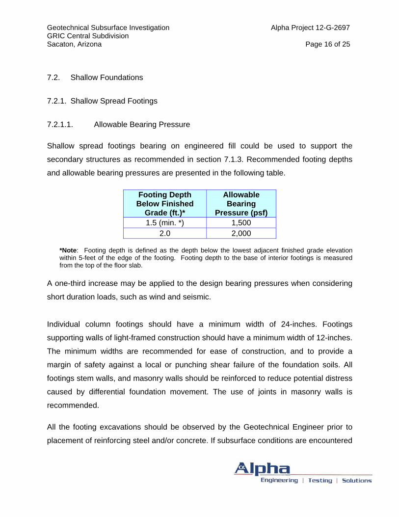
Shallow spread footings bearing on engineered fill could be used to support the
secondary structures as recommended in section 7.1.3. Recommended footing depths
and allowable bearing pressures are presented in the following table.
*Note: Footing depth is defined as the depth below the lowest adjacent finished grade elevation within 5-feet of the edge of the footing. Footing depth to the base of interior footings is measured from the top of the floor slab.
A one-third increase may be applied to the design bearing pressures when considering
short duration loads, such as wind and seismic.
Individual column footings should have a minimum width of 24-inches. Footings
supporting walls of light-framed construction should have a minimum width of 12-inches.
The minimum widths are recommended for ease of construction, and to provide a
margin of safety against a local or punching shear failure of the foundation soils. All
footings stem walls, and masonry walls should be reinforced to reduce potential distress
caused by differential foundation movement. The use of joints in masonry walls is
recommended.
All the footing excavations should be observed by the Geotechnical Engineer prior to
placement of reinforcing steel and/or concrete. If subsurface conditions are encountered
Footing Depth Below Finished
Grade (ft.)*
Allowable Bearing
Pressure (psf) 1.5 (min. *) 1,500
2.0 2,000
Geotechnical Subsurface Investigation Alpha Project 12-G-2697 GRIC Central Subdivision Sacaton, Arizona Page 17 of 25
that are different than indicated by the test borings, revised recommendations may be
required.
7.2.1.2. Estimated Settlements
Settlement of footings designed as recommended above are estimated not to exceed
¾-inch. Differential settlements between similarly loaded, adjacent footings are
expected to be less than ½-inch. Significant moisture increases above those
recommended for compaction could result in additional movements. In order to
minimize the sensitivity of the structure to differential settlements, footings should be
reinforced to allow for a degree of load redistribution should a localized zone of
supporting soils become saturated.
7.2.2. Floor Slab
A modulus of subgrade reaction of 250 pound per cubic inch (PCI) may be used in
design of the concrete slabs-on-grade. This modulus of subgrade reaction is based on
soils encountered during our field exploration, recommendations for subgrade soils
preparation stated within the above referenced report, our experience with similar
subgrade conditions and estimates obtained from ACI design charts.
7.2.3. Structural slabs (post-tensioned or reinforced mat-type slabs)
Structural slabs (post-tensioned or reinforced mat-type slabs) are recommended to
support the structures.
Based on the design procedure outlined in the Post-Tensioning Institute’s Design and
Construction of Post-Tensioned Slabs-on-Ground, 3rd Edition, including addendum 1
Geotechnical Subsurface Investigation Alpha Project 12-G-2697 GRIC Central Subdivision Sacaton, Arizona Page 18 of 25
dated May 21, 2007 and addendum 2 dated May 2008, the site soils classifies as Non-
Active.
Recommended design parameters:
Maximum Allowable Bearing Pressure, qa: 1250 psf (at grade)
Coefficient of Subgrade Reaction, k: 250 pci
Structures bearing on prepared subgrade as presented in the above section 6.2.2. Post-
Tensioned Floor Slab Preparation may experience total settlements up to ½ -inch.
Differential settlement is expected to be less than ¼-inch between similarly load areas.
The majority of the settlement is expected to occur during construction. Additional
foundation movements could occur if the supporting soils become wetted, please refer
to Section 7.3 Moisture Protection.
Post-tensioned slabs’ thickened or turn-down edges and/or interior beams should be
designed and constructed in accordance with the requirements of the Post-Tensioning
Institute and the American Concrete Institute.
7.2.4. Resistance to Lateral Loads
Proposed walls/structures that will retain soil must be designed to withstand lateral soil
pressures. Cantilevered retaining walls, or unrestrained walls subject to lateral earth
pressures, should be designed for an equivalent fluid pressure (EFP) of 32 PCF.
Restrained walls should be designed to withstand a residual or long-term at-rest (Ko)
earth pressure condition of 50 pounds per cubic foot (PCF).
A passive EFP of 354 PCF may be used for shallow spread footings. A coefficient of
friction of 0.43 is recommended for computing lateral resistance between the base of
Geotechnical Subsurface Investigation Alpha Project 12-G-2697 GRIC Central Subdivision Sacaton, Arizona Page 19 of 25
footing and soil in analyzing lateral loads. Vehicular surcharge loads and/or hydrostatic
pressure will increase the recommended EFP.
Only cohesionless, free-draining granular materials should be used as backfill, adjacent
to earth-retaining structures. We recommend that backfill directly behind the walls be
compacted with light, hand-held compactors. Heavy compactors and grading equipment
should not be allowed to operate within 3 feet of the walls during backfilling, to avoid
developing excessive temporary or long-term lateral soil pressures. Positive gravity
drainage of the backfill should be provided.
7.2.5. Retaining Walls
7.2.5.1. Lateral Earth Pressures
If retaining walls are utilized in this project, they should be designed to resist the earth
pressure exerted by the retained, compacted backfill plus any additional lateral force
that will be applied to the wall due to surface loads placed at or near the top of the wall.
The at-rest earth pressure against walls that are restrained at the top and with level
backfill may be taken as equivalent to the pressure exerted by a fluid weighing 50
pounds per cubic foot (pcf). Fifty percent of any uniform area surcharge placed at the
top of a restrained wall may be assumed to act as a uniform horizontal pressure over
the entire height of the wall.
Retaining walls that are not restrained at the top and with backfill, which is level behind
the wall, may be designed for an active earth pressure developed by an equivalent fluid
weighing 32 pcf. Thirty percent of any uniform surcharge may be assumed to act as a
uniform horizontal pressure over the entire height of the wall.
Geotechnical Subsurface Investigation Alpha Project 12-G-2697 GRIC Central Subdivision Sacaton, Arizona Page 20 of 25
7.2.5.2. Wall Drainage
The above-recommended values do not include lateral pressures due to hydrostatic
forces. Therefore, wall backfill should be free draining and provisions should be made
to collect and dispose of excess water that may accumulate behind earth retaining
structures.
Wall drainage should be collected by continuous perforated drainpipes, filter fabric, and
gravel connected to weep holes. The drainpipe must run parallel to the wall. We
recommend drainrock consist of durable stone having 100 percent passing the 1-inch
sieve and zero percent passing the No. 4 sieve. Synthetic filter fabric should have an
equivalent opening size (EOS), U.S. Standard Sieve, of between 40 and 70, a
permeability of at least 0.02 centimeters per second and minimum puncture strength of
50 pounds.
7.2.5.3. Backfill Placement
All backfill should be placed and compacted in accordance with recommendations
provided above for engineered fill. Light equipment should be used during backfill
compaction to minimize possible overstressing of the wall.
7.3. Moisture Protection
Positive drainage is essential to the successful performance of any foundation or slab
on grade. Good surface and subsurface drainage should be established during and
after construction to prevent the soils below or adjacent to the building areas from
becoming wet.
Infiltration of water into utility or foundation excavations must be prevented during
construction. The drainage design must route all storm and sprinkler water away from
Geotechnical Subsurface Investigation Alpha Project 12-G-2697 GRIC Central Subdivision Sacaton, Arizona Page 21 of 25
the buildings in a positive manner. All water should be diverted away from areas where
it could penetrate the ground surface near the buildings. If used, gutters and
downspouts should be designed to collect and direct roof runoff away from the building
foundations. In areas where sidewalks or pavements do not immediately adjoin the
structures, protective slopes should be provided. These slopes should have a minimum
5% grade for a distance of at least 10 feet from the perimeter of the foundations. Where
lot lines, walls, slopes or other physical barriers prohibit 6 inches of fall within 10 feet,
drains or swales shall be provided to ensure drainage away from the structure.
Watering of plants should be avoided adjacent to the buildings. Desert-type landscaping
is advisable near the building. Plants, which require more water, should be located and
drained away from the building areas.
7.4. Corrosion Potential
7.4.1. Sulfate and Chloride Content
Selected samples of the near-surface soils encountered at the site were subjected to
chemical analysis for the purpose of corrosion assessment. The samples were tested
for soluble sulfates, and soluble chlorides. The samples were tested in general
accordance with Arizona Test Methods 733, and 736 for soluble sulfates, and soluble
chlorides, respectively. The test results are provided in Appendix C.
Based on provisions of American Concrete Institute (ACI) 318 Section 4.3, Table 4.3.1,
Requirements for Concrete Exposed to Sulfate-Containing Solutions a sulfate
concentration below 0.10 percent by weight (1,000 ppm) is negligible. Based on the
laboratory results, sulfate contents of the site soils tested indicate a negligible to
approaching moderate corrosion potential to concrete.
Geotechnical Subsurface Investigation Alpha Project 12-G-2697 GRIC Central Subdivision Sacaton, Arizona Page 22 of 25
Based on results, ACI 318 recommends the use of concrete with a minimum design
compressive strength of 4,000 psi and a maximum water-cement ratio of 0.50 for
structural concrete.
Based on Standard Requirements for Design of Shallow Post-Tensioned Concrete
Foundations on Expansive Soils, dated May, 2008 published by Post-Tensioning
Institute, levels below 500 parts per million should be considered negligible for
concentrations of chlorides in soils as it pertains to steel tendons and reinforcing steel
cast in concrete. Based on the laboratory result, chloride contents of the site soils
tested indicate an elevated corrosion potential to concrete reinforcing. Please refer for
section 6.2.2 of the above referenced manual for mitigating methods.
Soluble salt content of representative soil samples was also measured; the results are
presented in appendix C.
7.4.2. Aggregate Base Course
Aggregate base used in support of concrete or asphalt pavements should conform to
the local governing and/or M.A.G. Section 702 Specifications. The plasticity index of the
fraction of material passing the No. 40 sieve should not exceed five when tested in
accordance with ASTM Test Method D 4318. Coarse aggregate should have a percent
of wear, when subjected to the Los Angeles abrasion test (ASTM Test Method C 131),
of no greater than 40.
All aggregate base should be placed in lifts not thicker than eight inches and compacted
to a minimum of 98 percent of maximum dry density as determined by American Society
for Testing and Materials (ASTM) Test Method D 698 or as specified by local
specifications. The moisture content during compaction should be maintained within
two percent of optimum moisture content.
Geotechnical Subsurface Investigation Alpha Project 12-G-2697 GRIC Central Subdivision Sacaton, Arizona Page 23 of 25
8. CLOSURE
8.1. Limitations
Our professional services have been performed using that degree and skill ordinarily
exercised, under similar circumstances, by reputable Geotechnical Engineers practicing
in this or similar localities. No warranty is expressed or implied.
The recommendations contained in this report are based on our field exploration,
laboratory test results, and our understanding of the proposed construction. The
subsurface data used in the preparation of this report was obtained from the test
borings excavated during the field subsurface exploration. It is anticipated that some
variations in the soil conditions will exist on-site. The nature and extent of variations
may not be evident until construction occurs. If any conditions are encountered at this
site that are different from those described in this report, we should be immediately
notified so that we may make any necessary revisions to the recommendations
contained in this report. In addition, if the scope of the proposed construction changes
from that described in this report, our firm should also be notified.
It is the Client’s responsibility to see that all parties to the project including the designer,
contractor, subcontractor, etc. are made aware of this report in its entirety. The use of
information contained in this report for bidding purposes should be done at the
contractor’s option and risk.
This report is for the exclusive purpose of providing Geotechnical Engineering and/or
testing information and recommendations. The scope of services for this project does
not include, either specifically or by implication, any environmental assessment of the
site or identification of contaminated or hazardous materials or conditions. If the owner
is concerned about the potential for such contamination, other studies should be
Geotechnical Subsurface Investigation Alpha Project 12-G-2697 GRIC Central Subdivision Sacaton, Arizona Page 24 of 25
undertaken. This report has also not addressed the site geology and the possible
presence of geologic hazards.
This report may be used only by the Client and only for the purposes stated, within a
reasonable time from its issuance. Land use, site conditions (both on and off-site), or
other factors may change over time, and additional work may be required with the
passage of time. Any party, other than the Client, who wishes to use this report, shall
notify Alpha of such intended use. Based on the intended use of this report, Alpha may
require that additional work be performed and that an updated report be issued.
8.2. Recommended Additional Services
The recommendations provided in this report are based on the assumption that an
adequate program of tests and observations will be performed during the construction.
These tests and observations should be performed by the Geotechnical Engineer’s
representative and should include, but are not necessarily be limited to the following:
Observe and document that any existing surficial vegetation and other deleterious materials have been removed from the site as required in site preparation section.
Approve any material used as engineered fill in building areas to document that it
meets the requirements outlined above before placement.
Monitor the scarification operations of the exposed subgrade.
Monitor footing excavation operations to document those footings are bearing in soils as recommended above.
Monitor the backfill procedures.
Perform field density tests, as needed, to verify compaction compliance. The
representative should monitor the progress of compaction and filling operations.
Geotechnical Subsurface Investigation Alpha Project 12-G-2697 GRIC Central Subdivision Sacaton, Arizona Page 25 of 25
Keep records of on-site activity and progress.
Observation of footing excavations should be performed prior to placement of
reinforcing and concrete to confirm that satisfactory bearing materials are present.
Construction testing, including field and laboratory evaluation of fill and backfill
materials, concrete and steel should be performed to determine whether applicable
project requirements have been met.

APPENDIX A Sample Location Plan
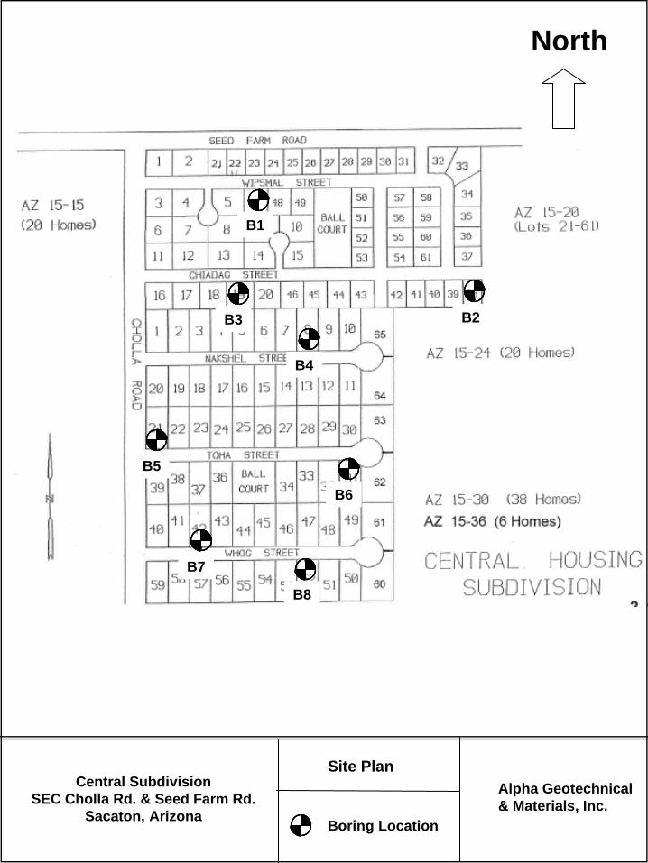
Site PlanCentral Subdivision
SEC Cholla Rd. & Seed Farm Rd.Sacaton, Arizona
Alpha Geotechnical& Materials, Inc.
Boring Location
North
B2
B1
B3
B8
B7
B6
B4
B5
APPENDIX B BORING LOGS
APPENDIX B FIELD INVESTIGATION
______________________________________________________________________ TEST BORINGS The subsurface conditions at the site were explored on July 12, 2012, by advancing 8 soil test borings using a CME 55 power drill rig. The locations of soil test borings performed for this investigation are shown in appendix A of the report. Our engineer maintained a log of the excavations; visually classified soils encountered according to the Unified Soil Classification System (USCS) (see USCS Table) and obtained samples of the subsurface materials. SAMPLING PROCEDURES Bulk samples were taken from the test borings at selected intervals. Soil samples were packaged and sealed in the field to reduce moisture loss and disturbance, and returned to our laboratory for further testing. After the soil test borings were completed, they were backfilled with the excavated soils. LIST OF ATTACHMENTS The following plates are attached and complete this appendix. Unified Soil Classification System Logs of Soil Test Borings
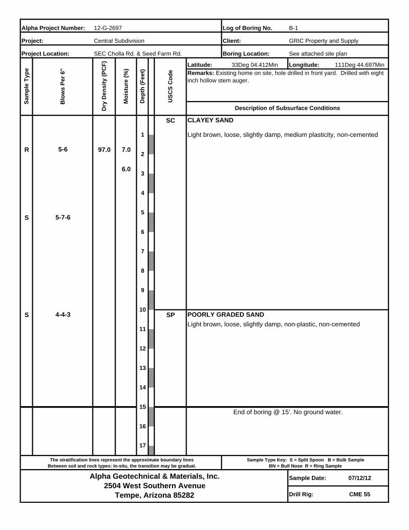
Log of Boring No.
Boring Location: See attached site plan
Latitude: Longitude: 111Deg 44.697Min
SC
R 97.0 7.0
6.0
S
S SP
Sample Date: 07/12/12
Drill Rig: CME 55
17
15
16
B-1
Blo
ws
Pe
r 6
"
Alpha Project Number:
Project Location:
12-G-2697S
am
ple
Ty
pe
Dry
De
ns
ity
(P
CF
)
SEC Cholla Rd. & Seed Farm Rd.
Mo
istu
re (
%)
5-6
Alpha Geotechnical & Materials, Inc.2504 West Southern Avenue
Tempe, Arizona 85282
5-7-6
4-4-3
CLAYEY SAND
The stratification lines represent the approximate boundary linesBetween soil and rock types: In-situ, the transition may be gradual.
Sample Type Key: S = Split Spoon B = Bulk SampleBN = Bull Nose R = Ring Sample
14
Light brown, loose, slightly damp, medium plasticity, non-cemented
POORLY GRADED SAND
Light brown, loose, slightly damp, non-plastic, non-cemented
End of boring @ 15'. No ground water.
1
13
12
11
10
5
4
3
2
9
8
7
6
33Deg 04.412Min
De
pth
(F
ee
t)
US
CS
Co
de Remarks: Existing home on site, hole drilled in front yard. Drilled with eight
inch hollow stem auger.
Description of Subsurface Conditions
Central Subdivision GRIC Property and SupplyProject: Client:
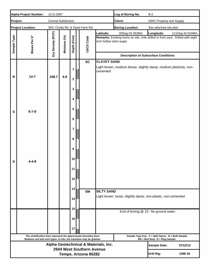
Log of Boring No.
Boring Location: See attached site plan
Latitude: Longitude: 111Deg 44.524Min
SC
R 108.7 6.8
S
S
SM
Sample Date: 07/12/12
Drill Rig: CME 55
Central Subdivision GRIC Property and SupplyProject: Client:
33Deg 04.353Min
De
pth
(F
ee
t)
US
CS
Co
de Remarks: Existing home on site, hole drilled in front yard. Drilled with eight
inch hollow stem auger.
Description of Subsurface Conditions
9
8
7
6
5
4
3
2
1
13
12
11
10
Light brown, loose, slightly damp, non-plastic, non-cemented
SILTY SAND
End of boring @ 15'. No ground water.
Light brown, medium dense, slightly damp, medium plasticity, non-cemented
CLAYEY SAND
The stratification lines represent the approximate boundary linesBetween soil and rock types: In-situ, the transition may be gradual.
Sample Type Key: S = Split Spoon B = Bulk SampleBN = Bull Nose R = Ring Sample
14
4-4-8
14-7
Alpha Geotechnical & Materials, Inc.2504 West Southern Avenue
Tempe, Arizona 85282
6-7-8
B-2
Blo
ws
Pe
r 6
"
Alpha Project Number:
Project Location:
12-G-2697S
am
ple
Ty
pe
Dry
De
ns
ity
(P
CF
)
SEC Cholla Rd. & Seed Farm Rd.
Mo
istu
re (
%)
17
15
16
Log of Boring No.
Boring Location: See attached site plan
Latitude: Longitude: 111Deg 44.707Min
SC
5.2
S
SP
S SC
S SP
Sample Date: 07/12/12
Drill Rig: CME 55
17
15
16
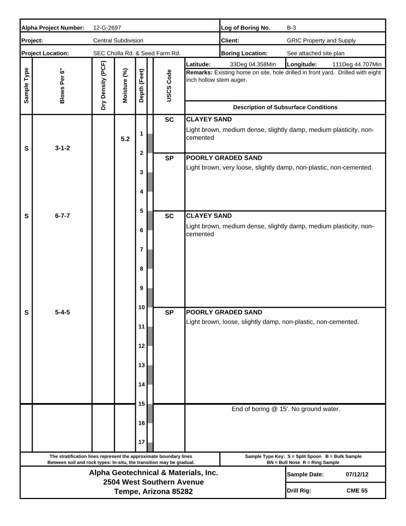
B-3
Blo
ws
Pe
r 6
"
Alpha Project Number:
Project Location:
12-G-2697S
am
ple
Ty
pe
Dry
De
ns
ity
(P
CF
)
SEC Cholla Rd. & Seed Farm Rd.
Mo
istu
re (
%)
3-1-2
Alpha Geotechnical & Materials, Inc.2504 West Southern Avenue
Tempe, Arizona 85282
6-7-7
5-4-5
CLAYEY SAND
The stratification lines represent the approximate boundary linesBetween soil and rock types: In-situ, the transition may be gradual.
Sample Type Key: S = Split Spoon B = Bulk SampleBN = Bull Nose R = Ring Sample
14
POORLY GRADED SAND
Light brown, medium dense, slightly damp, medium plasticity, non-cemented
Light brown, very loose, slightly damp, non-plastic, non-cemented.
CLAYEY SAND
Light brown, medium dense, slightly damp, medium plasticity, non-cemented
POORLY GRADED SAND
Light brown, loose, slightly damp, non-plastic, non-cemented.
End of boring @ 15'. No ground water.
1
13
12
11
10
5
4
3
2
9
8
7
6
33Deg 04.358Min
De
pth
(F
ee
t)
US
CS
Co
de Remarks: Existing home on site, hole drilled in front yard. Drilled with eight
inch hollow stem auger.
Description of Subsurface Conditions
Central Subdivision GRIC Property and SupplyProject: Client:
Log of Boring No.
Boring Location: See attached site plan
Latitude: Longitude: 111Deg 44.657Min
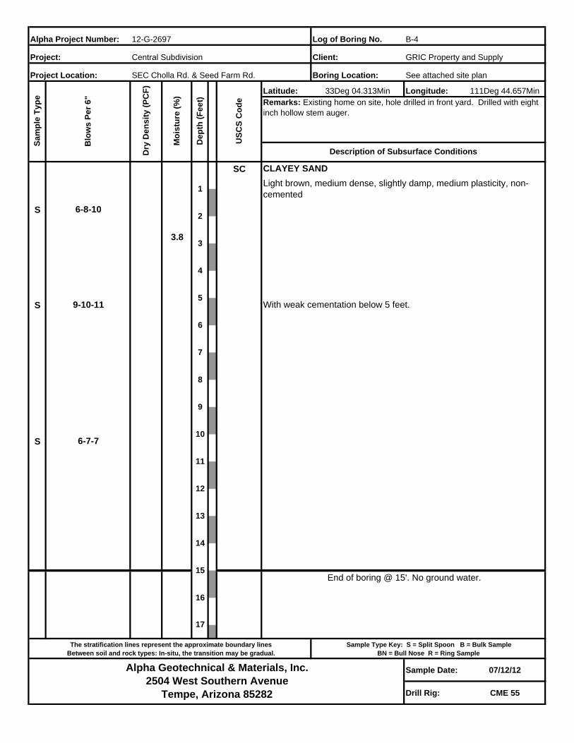
SC
S
3.8
S
S
Sample Date: 07/12/12
Drill Rig: CME 55
Central Subdivision GRIC Property and SupplyProject: Client:
33Deg 04.313Min
De
pth
(F
ee
t)
US
CS
Co
de Remarks: Existing home on site, hole drilled in front yard. Drilled with eight
inch hollow stem auger.
Description of Subsurface Conditions
9
8
7
6
5
4
3
2
1
13
12
11
10
End of boring @ 15'. No ground water.
With weak cementation below 5 feet.
Light brown, medium dense, slightly damp, medium plasticity, non-cemented
CLAYEY SAND
The stratification lines represent the approximate boundary linesBetween soil and rock types: In-situ, the transition may be gradual.
Sample Type Key: S = Split Spoon B = Bulk SampleBN = Bull Nose R = Ring Sample
14
6-7-7
6-8-10
Alpha Geotechnical & Materials, Inc.2504 West Southern Avenue
Tempe, Arizona 85282
9-10-11
B-4
Blo
ws
Pe
r 6
"
Alpha Project Number:
Project Location:
12-G-2697S
am
ple
Ty
pe
Dry
De
ns
ity
(P
CF
)
SEC Cholla Rd. & Seed Farm Rd.
Mo
istu
re (
%)
17
15
16
Log of Boring No.
Boring Location: See attached site plan
Latitude: Longitude: 111Deg 44.766Min
SC
S
5.7
S
S SP
Sample Date: 07/12/12
Drill Rig: CME 55
17
15
16
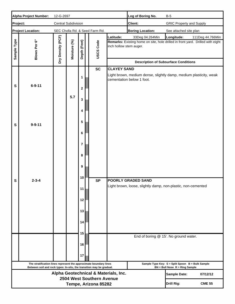
B-5
Blo
ws
Pe
r 6
"
Alpha Project Number:
Project Location:
12-G-2697S
am
ple
Ty
pe
Dry
De
ns
ity
(P
CF
)
SEC Cholla Rd. & Seed Farm Rd.
Mo
istu
re (
%)
6-9-11
Alpha Geotechnical & Materials, Inc.2504 West Southern Avenue
Tempe, Arizona 85282
9-9-11
2-3-4
CLAYEY SAND
The stratification lines represent the approximate boundary linesBetween soil and rock types: In-situ, the transition may be gradual.
Sample Type Key: S = Split Spoon B = Bulk SampleBN = Bull Nose R = Ring Sample
14
Light brown, medium dense, slightly damp, medium plasticity, weak cementation below 1 foot.
POORLY GRADED SAND
Light brown, loose, slightly damp, non-plastic, non-cemented
End of boring @ 15'. No ground water.
1
13
12
11
10
5
4
3
2
9
8
7
6
33Deg 04.264Min
De
pth
(F
ee
t)
US
CS
Co
de Remarks: Existing home on site, hole drilled in front yard. Drilled with eight
inch hollow stem auger.
Description of Subsurface Conditions
Central Subdivision GRIC Property and SupplyProject: Client:
Log of Boring No.
Boring Location: See attached site plan
Latitude: Longitude: 111Deg 44.639Min
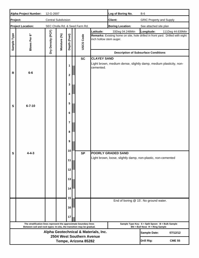
SC
R
S
S SP
Sample Date: 07/12/12
Drill Rig: CME 55
Central Subdivision GRIC Property and SupplyProject: Client:
33Deg 04.248Min
De
pth
(F
ee
t)
US
CS
Co
de Remarks: Existing home on site, hole drilled in front yard. Drilled with eight
inch hollow stem auger.
Description of Subsurface Conditions
9
8
7
6
5
4
3
2
1
13
12
11
10
End of boring @ 15'. No ground water.
POORLY GRADED SAND
Light brown, loose, slightly damp, non-plastic, non-cemented
Light brown, medium dense, slightly damp, medium plasticity, non-cemented.
CLAYEY SAND
The stratification lines represent the approximate boundary linesBetween soil and rock types: In-situ, the transition may be gradual.
Sample Type Key: S = Split Spoon B = Bulk SampleBN = Bull Nose R = Ring Sample
14
4-4-3
6-6
Alpha Geotechnical & Materials, Inc.2504 West Southern Avenue
Tempe, Arizona 85282
6-7-10
B-6
Blo
ws
Pe
r 6
"
Alpha Project Number:
Project Location:
12-G-2697S
am
ple
Ty
pe
Dry
De
ns
ity
(P
CF
)
SEC Cholla Rd. & Seed Farm Rd.
Mo
istu
re (
%)
17
15
16
Log of Boring No.
Boring Location: See attached site plan
Latitude: Longitude: 111Deg 44.739Min
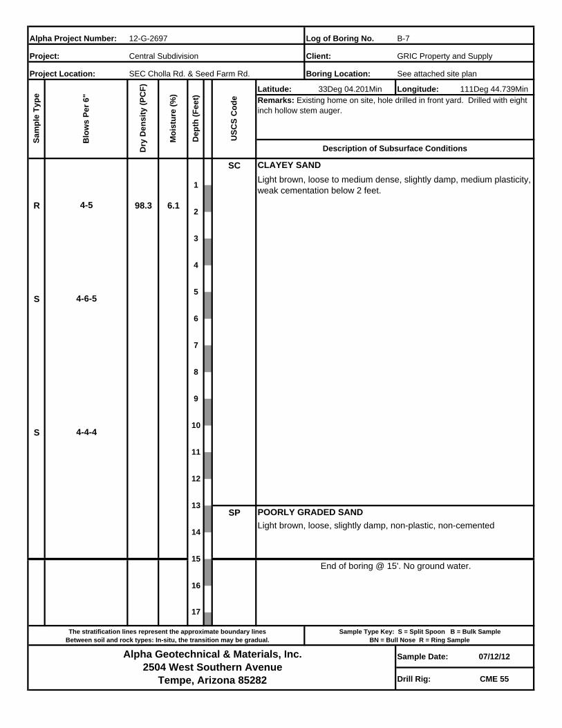
SC
R 98.3 6.1
S
S
SP
Sample Date: 07/12/12
Drill Rig: CME 55
17
15
16
B-7
Blo
ws
Pe
r 6
"
Alpha Project Number:
Project Location:
12-G-2697S
am
ple
Ty
pe
Dry
De
ns
ity
(P
CF
)
SEC Cholla Rd. & Seed Farm Rd.
Mo
istu
re (
%)
4-5
Alpha Geotechnical & Materials, Inc.2504 West Southern Avenue
Tempe, Arizona 85282
4-6-5
4-4-4
CLAYEY SAND
The stratification lines represent the approximate boundary linesBetween soil and rock types: In-situ, the transition may be gradual.
Sample Type Key: S = Split Spoon B = Bulk SampleBN = Bull Nose R = Ring Sample
14
Light brown, loose to medium dense, slightly damp, medium plasticity, weak cementation below 2 feet.
Light brown, loose, slightly damp, non-plastic, non-cemented
POORLY GRADED SAND
End of boring @ 15'. No ground water.
1
13
12
11
10
5
4
3
2
9
8
7
6
33Deg 04.201Min
De
pth
(F
ee
t)
US
CS
Co
de Remarks: Existing home on site, hole drilled in front yard. Drilled with eight
inch hollow stem auger.
Description of Subsurface Conditions
Central Subdivision GRIC Property and SupplyProject: Client:
Log of Boring No.
Boring Location: See attached site plan
Latitude: Longitude: 111Deg 44.666Min
SC
S
5.1
S
S SP
Sample Date: 07/12/12
Drill Rig: CME 55
Central Subdivision GRIC Property and SupplyProject: Client:
33Deg 04.181Min
De
pth
(F
ee
t)
US
CS
Co
de Remarks: Existing home on site, hole drilled in front yard. Drilled with eight
inch hollow stem auger.
Description of Subsurface Conditions
9
8
7
6
5
4
3
2
1
13
12
11
10
End of boring @ 15'. No ground water.
POORLY GRADED SAND
Light brown, loose, slightly damp, non-plastic, non-cemented
Light brown, loose to medium dense, slightly damp, medium plasticity, weak cementation below 1 foot.
CLAYEY SAND
The stratification lines represent the approximate boundary linesBetween soil and rock types: In-situ, the transition may be gradual.
Sample Type Key: S = Split Spoon B = Bulk SampleBN = Bull Nose R = Ring Sample
14
7-5-5
4-4-4
Alpha Geotechnical & Materials, Inc.2504 West Southern Avenue
Tempe, Arizona 85282
5-7-8
B-8
Blo
ws
Pe
r 6
"
Alpha Project Number:
Project Location:
12-G-2697S
am
ple
Ty
pe
Dry
De
ns
ity
(P
CF
)
SEC Cholla Rd. & Seed Farm Rd.
Mo
istu
re (
%)
17
15
16
APPENDIX C Laboratory Test
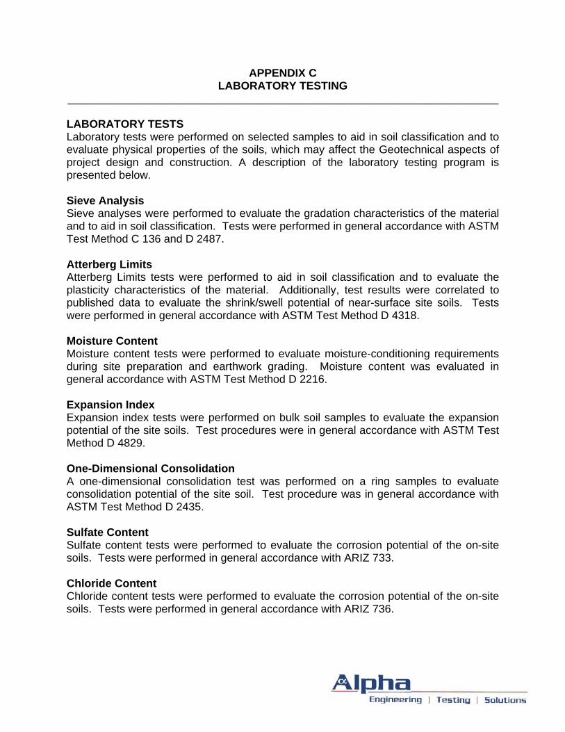
APPENDIX C LABORATORY TESTING
______________________________________________________________________ LABORATORY TESTS Laboratory tests were performed on selected samples to aid in soil classification and to evaluate physical properties of the soils, which may affect the Geotechnical aspects of project design and construction. A description of the laboratory testing program is presented below. Sieve Analysis Sieve analyses were performed to evaluate the gradation characteristics of the material and to aid in soil classification. Tests were performed in general accordance with ASTM Test Method C 136 and D 2487. Atterberg Limits Atterberg Limits tests were performed to aid in soil classification and to evaluate the plasticity characteristics of the material. Additionally, test results were correlated to published data to evaluate the shrink/swell potential of near-surface site soils. Tests were performed in general accordance with ASTM Test Method D 4318. Moisture Content Moisture content tests were performed to evaluate moisture-conditioning requirements during site preparation and earthwork grading. Moisture content was evaluated in general accordance with ASTM Test Method D 2216. Expansion Index Expansion index tests were performed on bulk soil samples to evaluate the expansion potential of the site soils. Test procedures were in general accordance with ASTM Test Method D 4829. One-Dimensional Consolidation A one-dimensional consolidation test was performed on a ring samples to evaluate consolidation potential of the site soil. Test procedure was in general accordance with ASTM Test Method D 2435. Sulfate Content Sulfate content tests were performed to evaluate the corrosion potential of the on-site soils. Tests were performed in general accordance with ARIZ 733. Chloride Content Chloride content tests were performed to evaluate the corrosion potential of the on-site soils. Tests were performed in general accordance with ARIZ 736.
Project: Central Housing Subdivision Project Number: 12-G-2697
Project Location: SEC Cholla Rd. & Seed Farm Rd.
Client: GRIC Property & Supply Sample Date:
Sample Source: See Below Material: Native
Silt or
Clay
Sample Number Location & Depth USCS LL PI #200 #100 #50 #40 #30 #16 #10 #8 #4 1/4" 3/8" 1/2" 3/4" 1" 1 1/4" 1 1/2" 2" 3" %
14015 Bulk Sample B-1 @ 0'-5' SC 31 14 46 100 6.0
14017 Bulk Sample B-3 @ 0'-2' SC 31 12 40 100 5.2
14018 Bulk Sample B-4 @ 0'-5' SC-SM 27 6 39 100 3.8
14019 Bulk Sample B-5 @ 0'-5' SC 33 13 42 100 5.7
14022 Bulk Sample B-8 @ 2'-5' SC 28 9 39 100 5.1
Sieve Screens Not Included in Test
Reviewed By: RS
Group Symbol, USCS (ASTM D-2487)
Gravel
07/12/12
Alpha Geotechnical & Materials, Inc.
Mechanical Sieve Analysis
Coarse
Percent Passing By Weight
Sand
FineCoarseMedium FineMoisture
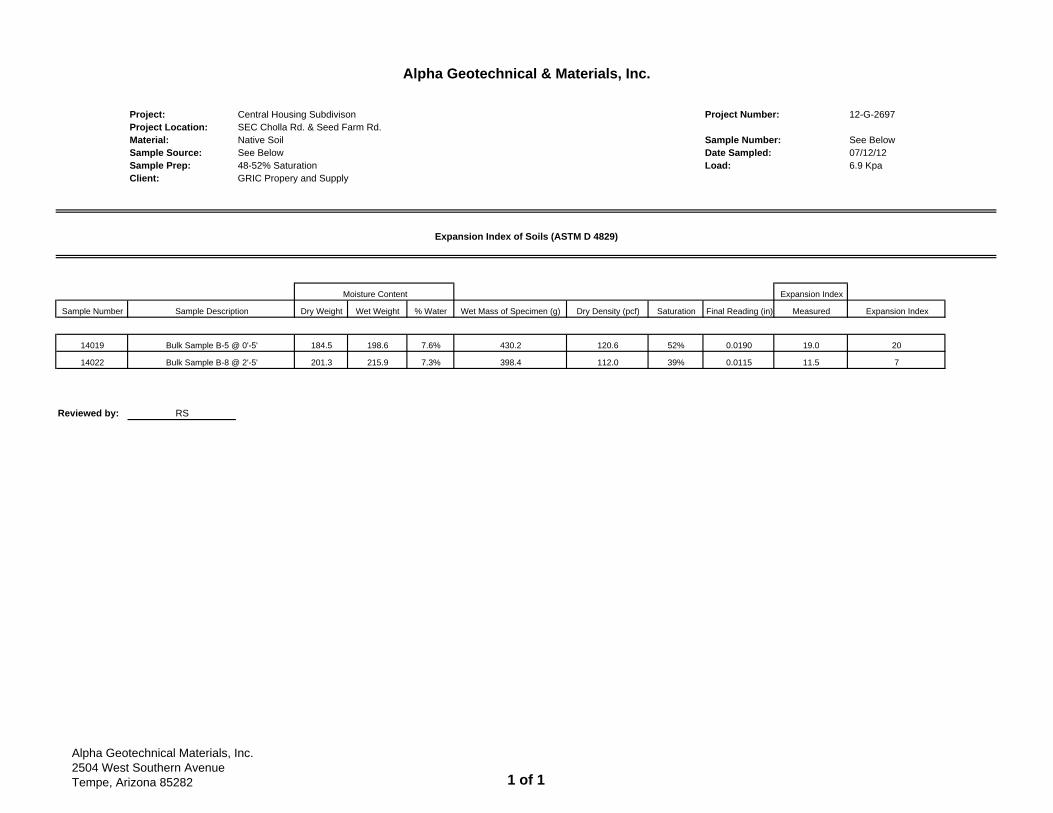
Project: Central Housing Subdivison Project Number: 12-G-2697Project Location: SEC Cholla Rd. & Seed Farm Rd.Material: Native Soil Sample Number: See BelowSample Source: See Below Date Sampled: 07/12/12Sample Prep: 48-52% Saturation Load: 6.9 KpaClient: GRIC Propery and Supply
Expansion Index
Sample Number Dry Weight Wet Weight % Water Wet Mass of Specimen (g) Dry Density (pcf) Saturation Final Reading (in) Measured Expansion Index
14019 184.5 198.6 7.6% 430.2 120.6 52% 0.0190 19.0 20
14022 201.3 215.9 7.3% 398.4 112.0 39% 0.0115 11.5 7
Reviewed by: RS
Alpha Geotechnical & Materials, Inc.
Expansion Index of Soils (ASTM D 4829)
Moisture Content
Sample Description
Bulk Sample B-5 @ 0'-5'
Bulk Sample B-8 @ 2'-5'
Alpha Geotechnical Materials, Inc.2504 West Southern AvenueTempe, Arizona 85282 1 of 1
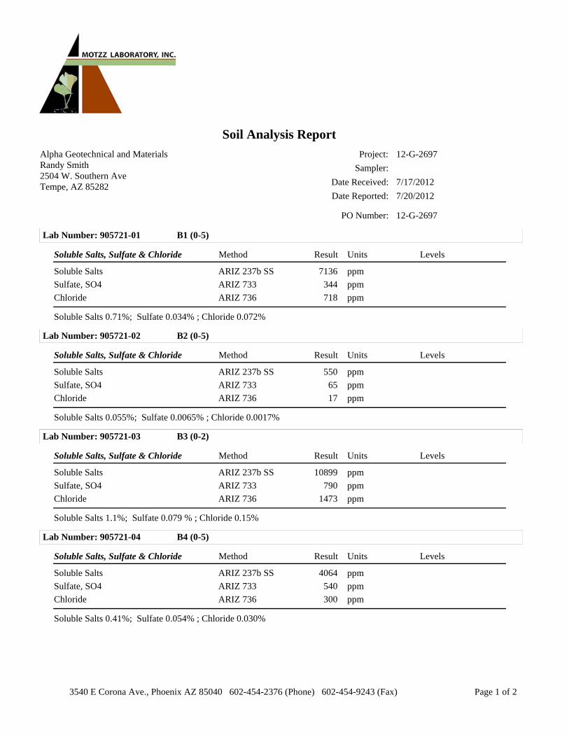
Alpha Geotechnical and MaterialsRandy Smith2504 W. Southern AveTempe, AZ 85282
Date Reported: 7/20/2012
Date Received: 7/17/2012
Project: 12-G-2697
Soil Analysis Report
PO Number: 12-G-2697
Sampler:
Lab Number: 905721-01 B1 (0-5)
Soluble Salts, Sulfate & Chloride UnitsMethod Result Levels
7136ARIZ 237b SS ppmSoluble Salts
344ARIZ 733 ppmSulfate, SO4
718ARIZ 736 ppmChloride
Soluble Salts 0.71%; Sulfate 0.034% ; Chloride 0.072%
Lab Number: 905721-02 B2 (0-5)
Soluble Salts, Sulfate & Chloride UnitsMethod Result Levels
550ARIZ 237b SS ppmSoluble Salts
65ARIZ 733 ppmSulfate, SO4
17ARIZ 736 ppmChloride
Soluble Salts 0.055%; Sulfate 0.0065% ; Chloride 0.0017%
Lab Number: 905721-03 B3 (0-2)
Soluble Salts, Sulfate & Chloride UnitsMethod Result Levels
10899ARIZ 237b SS ppmSoluble Salts
790ARIZ 733 ppmSulfate, SO4
1473ARIZ 736 ppmChloride
Soluble Salts 1.1%; Sulfate 0.079 % ; Chloride 0.15%
Lab Number: 905721-04 B4 (0-5)
Soluble Salts, Sulfate & Chloride UnitsMethod Result Levels
4064ARIZ 237b SS ppmSoluble Salts
540ARIZ 733 ppmSulfate, SO4
300ARIZ 736 ppmChloride
Soluble Salts 0.41%; Sulfate 0.054% ; Chloride 0.030%
3540 E Corona Ave., Phoenix AZ 85040 602-454-2376 (Phone) 602-454-9243 (Fax) Page 1 of 2

Alpha Geotechnical and MaterialsRandy Smith2504 W. Southern AveTempe, AZ 85282
Date Reported: 7/20/2012
Date Received: 7/17/2012
Project: 12-G-2697
Soil Analysis Report
PO Number: 12-G-2697
Sampler:
Lab Number: 905721-05 B5 (0-5)
Soluble Salts, Sulfate & Chloride UnitsMethod Result Levels
4051ARIZ 237b SS ppmSoluble Salts
491ARIZ 733 ppmSulfate, SO4
611ARIZ 736 ppmChloride
Soluble Salts 0.41%; Sulfate 0.049% ; Chloride 0.061%
Lab Number: 905721-06 B6 (0-5)
Soluble Salts, Sulfate & Chloride UnitsMethod Result Levels
4614ARIZ 237b SS ppmSoluble Salts
406ARIZ 733 ppmSulfate, SO4
668ARIZ 736 ppmChloride
Soluble Salts 0.46%; Sulfate 0.041% ; Chloride 0.067%
Lab Number: 905721-07 B7 (0-5)
Soluble Salts, Sulfate & Chloride UnitsMethod Result Levels
6406ARIZ 237b SS ppmSoluble Salts
979ARIZ 733 ppmSulfate, SO4
977ARIZ 736 ppmChloride
Soluble Salts 0.64%; Sulfate 0.098% ; Chloride 0.098%
Lab Number: 905721-08 B8 (0-5)
Soluble Salts, Sulfate & Chloride UnitsMethod Result Levels
7001ARIZ 237b SS ppmSoluble Salts
438ARIZ 733 ppmSulfate, SO4
937ARIZ 736 ppmChloride
Soluble Salts 0.70%; Sulfate 0.044% ; Chloride 0.094%
3540 E Corona Ave., Phoenix AZ 85040 602-454-2376 (Phone) 602-454-9243 (Fax) Page 2 of 2