Embed Size (px)
Citation preview
Report of Subsurface Exploration and Geotechnical Engineering Evaluation Rockbridge Elementary School Stone Mountain, Georgia DCSD Project Number 508-422
Prepared for DeKalb County School District December 10, 2012

1000 Cobb Place Blvd., Suite 290 • Kennesaw, Georgia 30144-3684 770/426-7100 • Fax: 770/426-5209 • www.geohydro.com
Mr. David M. Lamutt December 10, 2012 Program Director DeKalb County School District Sam Moss Center 1780 Montreal Road Tucker, Georgia 30084
Report of Subsurface Exploration and Geotechnical Engineering Evaluation
Rockbridge Elementary School Stone Mountain, Georgia
DCSD Project Number 508-422 Geo-Hydro Project Number 120557.00
Dear Mr. Lamutt: Geo-Hydro Engineers, Inc. has completed the authorized subsurface exploration for the above referenced project. The scope of services for this project was outlined in our proposal number 15505 dated November 16, 2012.
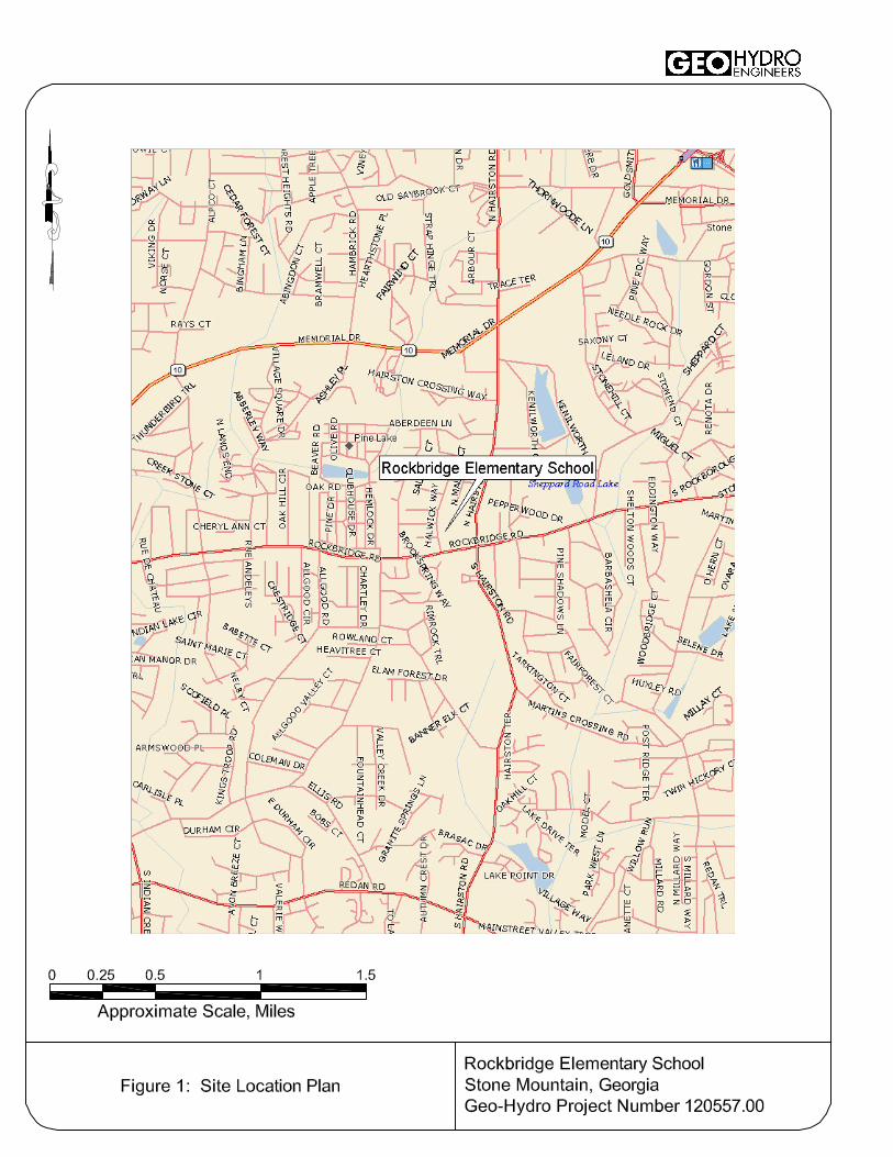
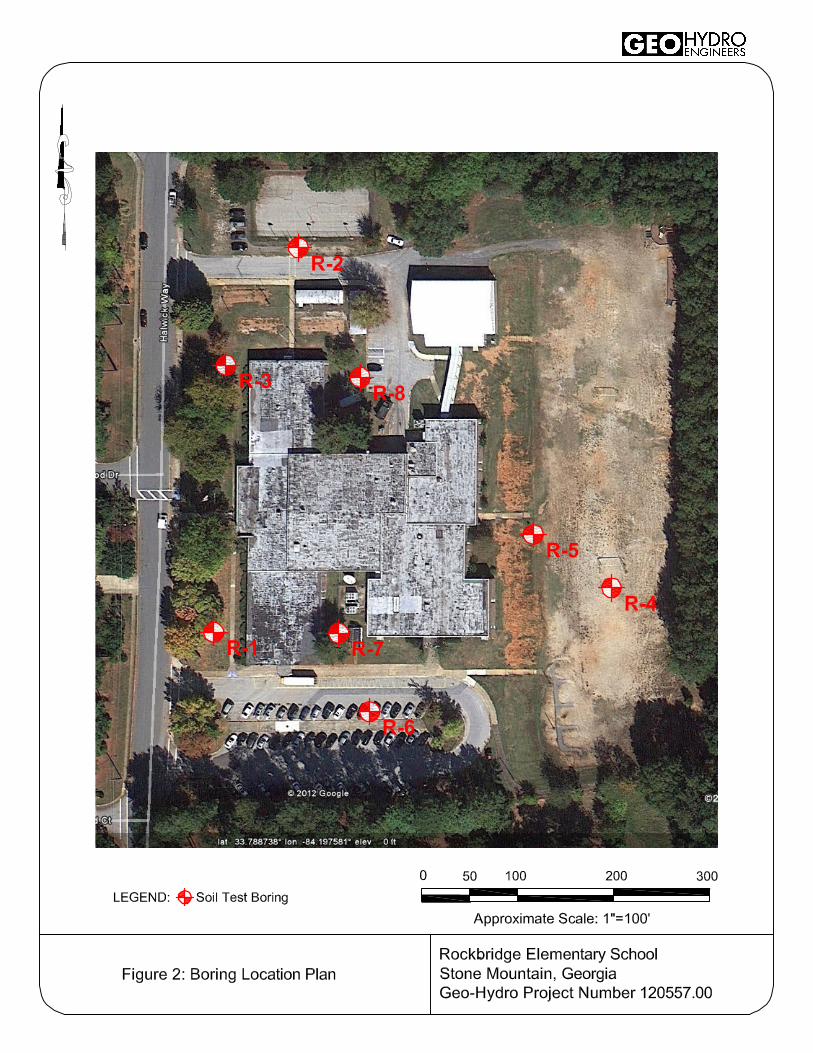
Project Information The existing Rockbridge Elementary School is located at 445 Halwick Way in Stone Mountain, Georgia. Figure 1 in the Appendix shows the approximate site location. We understand that a prototype elementary school is being planned for seven possible replacement schools. The prototype has yet to be designed. The purpose of this exploration was to determine the overall subsurface conditions at this site for development of the prototype plan. We understand that the desired school design will include a typical one- to two-story elementary school. We have assumed that the building construction will consist of masonry walls and a concrete slab-on-grade floor system. No structural load information is presently available, and we have assumed that the maximum column load will be no greater than 200 kips, and that the maximum wall load will be no greater than 3 kips per lineal foot. Currently, the site is developed with an existing elementary school and contains parking areas, play fields, sidewalks, and landscaped areas. The property is tiered with the eastern play field being on the lower portion of the site. At the time of this report, site grading is unknown and will be greatly influenced by the layout of the new building. Pictures in the Appendix show the site at the time of our field exploration.
Exploratory Procedures
The subsurface exploration included eight machine-drilled soil test borings performed at the approximate locations shown on Figure 2 included in the Appendix. The test borings were located in the field by Geo-Hydro by measuring angles and distances from existing site features. In general, the locations of the borings should be considered approximate.
Rockbridge Elementary School Stone Mountain, Georgia Project Number 120557.00
December 10, 2012 | 2
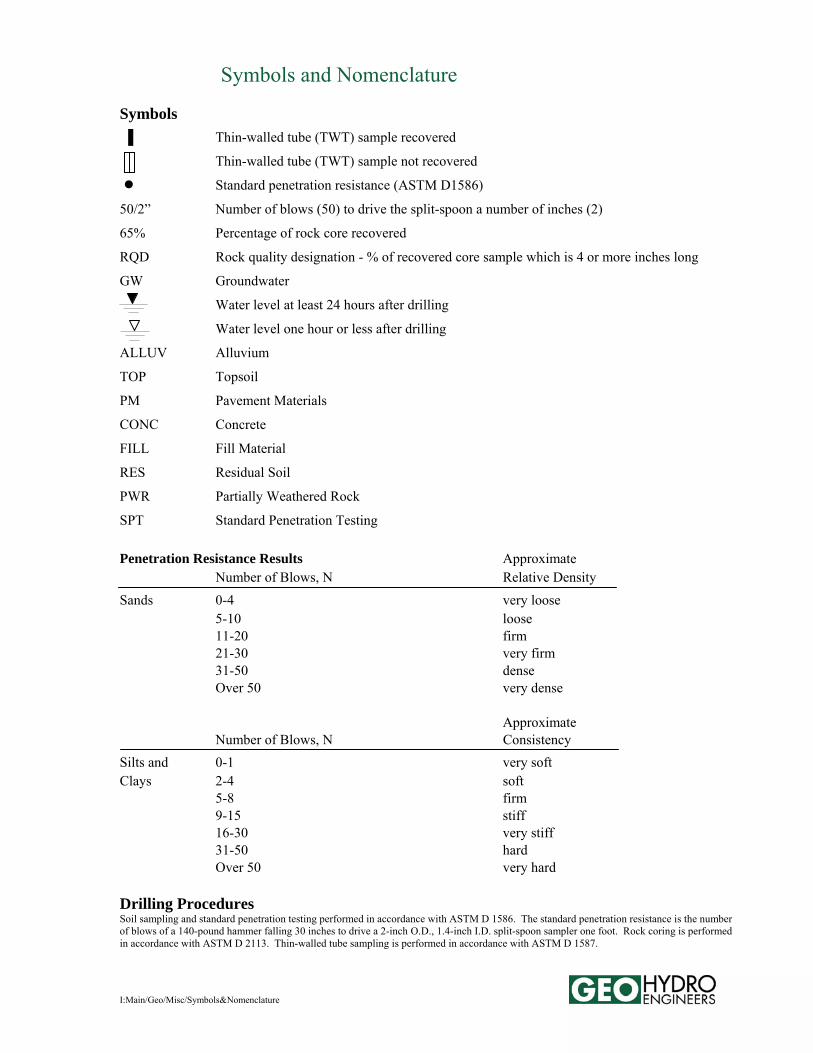
Standard penetration testing, as provided for in ASTM D-l586, was performed at selected intervals in the soil test borings. Soil samples obtained from the drilling operation were examined and classified in general accordance with ASTM D-2488 (Visual-Manual Procedure for Description of Soils). Soil classifications include the use of the Unified Soil Classification System described in ASTM D-2487 (Classification of Soils for Engineering Purposes). The soil classifications also include our evaluation of the geologic origin of the soils. Evaluations of geologic origin are based on our experience and interpretation and may be subject to some degree of error. Descriptions of the soils encountered, groundwater conditions, standard penetration resistances, and other pertinent information are provided in the test boring records and hand auger logs included in the Appendix.
Regional Geology The project site is located in the Southern Piedmont Geologic Province of Georgia. Soils in this area have been formed by the in-place weathering of the underlying crystalline rock, which accounts for their classification as “residual” soils. Residual soils near the ground surface that have experienced advanced weathering frequently consist of red brown clayey silt (ML) or silty clay (CL). The thickness of this surficial clayey zone may range up to roughly 6 feet. For various reasons, such as erosion or local variation of mineralization, the upper clayey zone is not always present. With increased depth, the soil becomes less weathered, coarser grained, and the structural character of the underlying parent rock becomes more evident. These residual soils are typically classified as sandy micaceous silt (ML) or silty micaceous sand (SM). With a further increase in depth, the soils eventually become quite hard and take on an increasing resemblance to the underlying parent rock. When these materials have a standard penetration resistance of l00 blows per foot or greater, they are referred to as partially weathered rock. The transition from soil to partially weathered rock is usually a gradual one, and may occur at a wide range of depths. Lenses or layers of partially weathered rock are not unusual in the soil profile. Partially weathered rock represents the zone of transition between the soil and the indurated metamorphic rocks from which the soils are derived. The subsurface profile is, in fact, a history of the weathering process that the crystalline rock has undergone. The degree of weathering is most advanced at the ground surface, where fine-grained soil may be present. Conversely, the weathering process is in its early stages immediately above the surface of relatively sound rock, where partially weathered rock may be found. The thickness of the zone of partially weathered rock and the depth to the rock surface have both been found to vary considerably over relatively short distances. The depth to the rock surface may frequently range from the ground surface to 80 feet or more. The thickness of partially weathered rock, which overlies the rock surface, may vary from only a few inches to as much as 40 feet or more. Geologic conditions at the site have been modified by previous construction activities.
Rockbridge Elementary School Stone Mountain, Georgia Project Number 120557.00
December 10, 2012 | 3
Soil Test Boring Summary Seven of the boring initially encountered surface materials consisting of topsoil or asphalt pavement materials. Topsoil thicknesses ranged from approximately 2 to 3 inches. Boring R-6 encountered about 5 inches of asphalt pavement. The thickness of surface materials at the site should be expected to vary, and measurements necessary for detailed quantity estimation were not performed for this report. For planning purposes, we suggest considering a topsoil thickness of about 6 inches to account for existing sparse vegetation and shallow roots. Beneath surface materials, borings R-4 and R-6 encountered fill materials extending to a depth of about 3 feet. The fill materials were classified as sandy silt or silty sand with varying mica content. Standard penetration resistances recorded in the fill were 12 blows per foot in R-4 and greater than 100 blows per foot in R-6. It should be noted that rock fragments and other hard materials within the fill will typically amplify the standard penetration resistance. Such higher standard penetration resistances are not a reliable indicator of the condition of the fill. Beneath surface materials or fill materials, all of the borings encountered residual soils typical of the Piedmont region. The residual soils were generally classified as silty sand or sandy silt with varying mica content. Standard penetration resistances in the residual soils ranged from 4 to 68 blows per foot. Partially weathered rock was encountered in boring R-6 at a depth of about 12 feet. The partially weathered rock was sampled as silty sand with varying mica content. Partially weathered rock is locally defined as residual material having standard penetration resistance values greater than 100 blows per foot. Auger refusal was encountered in boring R-7 at a depth of 13 feet and in boring R-8 at a depth of 23 feet. Auger refusal is the condition that prevents advancement of the boring using conventional soil drilling techniques. The material causing auger refusal may consist of a boulder, a lens or layer of rock, the upper surface of relatively massive rock, or other hard material. At the time of drilling, groundwater was not encountered in any of the test borings. For safety reasons the borings were backfilled upon completion. It should be noted that groundwater levels will fluctuate depending on yearly and seasonal rainfall variations and other factors, and may rise in the future. For more detailed descriptions of subsurface conditions, please refer to the test boring records and hand auger logs included in the Appendix.
Rockbridge Elementary School Stone Mountain, Georgia Project Number 120557.00
December 10, 2012 | 4
Preliminary Evaluations and Recommendations The following evaluations and recommendations are based on the information available on the proposed construction, the data obtained from the test borings, and our experience with soils and subsurface conditions similar to those encountered at this site. Because the test borings represent a statistically small sampling of subsurface conditions, it is possible that conditions may be encountered during supplemental exploration and during construction that are substantially different from those indicated by the test borings. In these instances, adjustments to the design and construction may be necessary. Geotechnical Considerations The following geotechnical characteristics of the site should be taken into account for planning and design:
The test borings indicate generally favorable excavation conditions within the anticipated excavation
limits. Fill materials and residual soils should be readily excavatable using conventional soil excavation equipment such as loaders and backhoes.
Two of the 8 test borings encountered fill materials extending to a depth of about 3 feet. Overall, the
quality and consistency of fill materials are variable. Variations within fill materials throughout the site should be expected, and poor quality fill may be encountered outside of the areas directly explored. Remedial measures including ground stabilization, excavation and replacement, and stone replacement in select foundation excavations should be expected.
Contingent upon proper site preparation and thorough evaluation of the foundation excavations, it is our opinion that the proposed building can be supported using conventional shallow foundations and concrete slab-on-grade floors. For design purposes, we recommend an allowable soil bearing pressure of 3,000 psf or less.
The following sections provide recommendations regarding these issues and other geotechnical aspects of the project. General Site Preparation Topsoil, roots, and other deleterious materials should be removed from the proposed construction area. All existing utilities should be excavated and removed unless they are to be incorporated into the new construction. Additionally, site clearing, grubbing, and stripping should be performed only during dry weather conditions. Operation of heavy equipment on the site during wet conditions could result in excessive rutting and mixing of topsoil and debris with underlying soils. All excavations resulting from demolition of foundations and basements and from rerouting of underground utilities should be backfilled in accordance with the Structural Fill section of this report. We recommend, wherever possible, that areas to receive structural fill be proofrolled prior to placement of structural fill. Areas of proposed excavation should be proofrolled after rough finished subgrade is achieved. Proofrolling should be performed with multiple passes in at least two directions using a fully
Rockbridge Elementary School Stone Mountain, Georgia Project Number 120557.00
December 10, 2012 | 5
loaded tandem axle dump truck weighing at least 18 tons. If low consistency soils are encountered that cannot be adequately densified in place, such soils should be removed and replaced with well compacted fill material placed in accordance with the Structural Fill section of this report. Proofrolling should be observed by Geo-Hydro to determine if remedial measures are necessary. During site preparation, burn pits or trash pits may be encountered. This is not an unusual occurrence on sites located in developed areas. All too frequently such buried material occurs in isolated areas which are not detected by the soil test borings. Any buried debris or trash found during the construction operation should be thoroughly excavated and removed from the site. Excavation Characteristics The test borings indicate generally favorable excavation conditions. Fill materials and residual soils should be readily excavatable using conventional soil excavation equipment such as loaders and backhoes. For construction bidding and field verification purposes it is common to provide a verifiable definition of rock in the project specifications. The following are typical definitions of mass rock and trench rock: Mass Rock: Material that cannot be excavated with a single-tooth ripper drawn by a crawler tractor
having a minimum draw bar pull rated at 56,000 pounds (Caterpillar D-8K or equivalent), and occupying an original volume of at least one cubic yard.
Trench Rock: Material occupying an original volume of at least one-half cubic yard which cannot be
excavated with a hydraulic excavator having a minimum flywheel power rating of 123 kW (165 hp); such as a Caterpillar 322C L, John Deere 230C LC, or a Komatsu PC220LC-7; equipped with a short tip radius bucket not wider than 42 inches.
Reuse of Excavated Materials Based on the results of test borings and our observations, the existing fill materials appear to be suitable for reuse as structural fill. However, it is possible that some excavated fill may not be suitable for reuse. Geo-Hydro should observe the excavation of existing fill materials to evaluate their suitability for reuse. Soft, unstable fill soils free of deleterious materials may be reusable after routine moisture adjustment (drying). Highly organic soils and debris-laden soils will not be suitable for reuse. The residual soils at the project site appear suitable for reuse as structural fill material. Routine adjustment of moisture content will be necessary to allow proper placement and compaction. Structural Fill Materials selected for use as structural fill should be free of organic debris, waste construction debris, and other deleterious materials. The material should not contain rocks having a diameter over 4 inches. It is our opinion that the following soils represented by their USCS group symbols will typically be suitable for use as structural fill and are usually found in abundance in the Piedmont: (SM), (ML), and (CL). The
Rockbridge Elementary School Stone Mountain, Georgia Project Number 120557.00
December 10, 2012 | 6
following soil types are typically suitable but are not abundant in the Piedmont: (SW), (SP), (SC), (SP-SM), and (SP-SC). The following soil types are considered unsuitable: (MH), (CH), (OL), (OH), and (Pt). Laboratory Proctor compaction tests and classification tests should be performed on representative samples obtained from the proposed borrow material to provide data necessary to determine acceptability and for quality control. The moisture content of suitable borrow soils should generally be no more than 3 percentage points below or above optimum at the time of compaction. Tighter moisture limits may be necessary with certain soils. It is possible that highly micaceous soils could be utilized as structural fill material. The use of such materials will require very close attention to quality control of moisture content and density. Additionally, it is our experience that highly micaceous soils tend to rut under rubber-tired vehicle traffic. Continuous maintenance of areas subjected to construction traffic is typically required until construction is completed. Suitable fill material should be placed in thin lifts. Lift thickness depends on the type of compaction equipment, but a maximum loose-lift thickness of 8 inches is generally recommended. The soil should be compacted by a self-propelled sheepsfoot roller. Within small excavations such as in utility trenches, around manholes, above foundations, or behind retaining walls, we recommend the use of “wacker packers” or “Rammax” compactors to achieve the specified compaction. Loose lift thicknesses of 4 to 6 inches are recommended in small area fills. We recommend that structural fill be compacted to at least 95 percent of the standard Proctor maximum dry density (ASTM D-698). The upper 12 inches of floor slab subgrade soils should be compacted to at least 98 percent of the standard Proctor maximum dry density. The upper 12 inches of pavement subgrades should be compacted in accordance with Georgia DOT requirements to at least 100 percent of the standard Proctor maximum dry density (ASTM D-698). Additionally, the maximum dry density of structural fill should be no less than 90 pcf. Geo-Hydro should perform density tests during fill placement. Earth Slopes Temporary construction slopes should be designed in strict compliance with OSHA regulations. The exploratory borings indicate that most soils at the site are Type B as defined in 29 CFR 1926.650 (1994 Edition). This dictates that temporary construction slopes in fill materials be no steeper than 1.5H:1V, and in residual soils temporary slopes must be no steeper than 1.H:1V for excavation depths of 20 feet or less. Temporary construction slopes should be closely observed on a daily basis by the contractor’s “competent person” for signs of mass movement: tension cracks near the crest, bulging at the toe of the slope, etc. The responsibility for excavation safety and stability of construction slopes should lie solely with the contractor. We recommend that extreme caution be observed in trench excavations. Several cases of loss of life due to trench collapses in Georgia point out the lack of attention given to excavation safety on some projects. We recommend that applicable local and federal regulations regarding temporary slopes, and shoring and bracing of trench excavations be closely followed.
Rockbridge Elementary School Stone Mountain, Georgia Project Number 120557.00
December 10, 2012 | 7
Formal analysis of slope stability was beyond the scope of work for this project. Based on our experience, permanent cut or fill slopes should be no steeper than 2H:1V to maintain long term stability and to provide ease of maintenance. The crest or toe of cut or fill slopes should be no closer than 10 feet to any foundation. The crest or toe should be no closer than 5 feet to the edge of any pavements. Erosion protection of slopes during construction and during establishment of vegetation should be considered an essential part of construction. Earth Pressure Three earth pressure conditions are generally considered for retaining wall design: "at rest", "active", and "passive" stress conditions. Retaining walls which are rigidly restrained at the top and will be essentially unable to rotate under the action of earth pressure (such as basement or foundation walls) should be designed for "at rest" conditions. Retaining walls which can move outward at the top as much as 0.5 percent of the wall height (such as free-standing walls) should be designed for "active" conditions. For the evaluation of the resistance of soil to lateral loads the "passive" earth pressure must be calculated. It should be noted that full development of passive pressure requires deflections toward the soil mass on the order of l.0 percent to 4.0 percent of total wall height. Earth pressure may be evaluated using the following equation:
ph = K (DwZ + qs) + Ww(Z-d)
where: ph = horizontal earth pressure at any depth below the ground surface (Z). Ww = unit weight of water Z = depth to any point below the ground surface d = depth to groundwater surface Dw = wet unit weight of the soil backfill (depending on borrow sources). The wet unit weight
of most residual soils may be expected to range from approximately 115 to 125 pcf. Below the groundwater level, Dw must be the buoyant weight.
qs = uniform surcharge load (add equivalent uniform surcharge to account for construction equipment loads)
K = earth pressure coefficient as follows:
Earth Pressure Condition Coefficient At Rest (Ko) 0.50 Active (Ka) 0.33 Passive (Kp) 3.0 The groundwater term, Ww(Z-d), should be used if no drainage system is incorporated behind retaining walls. If a drainage system is included which will not allow the development of any water pressure behind the wall, then the groundwater term may be omitted. The development of excessive water pressure is a common cause of retaining wall failures. Drainage systems should be carefully designed to insure that long term permanent drainage is accomplished.
Rockbridge Elementary School Stone Mountain, Georgia Project Number 120557.00
December 10, 2012 | 8
The above design recommendations are based on the following assumptions:
Horizontal backfill 95 percent standard Proctor compactive effort on backfill (ASTM D-698) No safety factor is included
For convenience, equivalent fluid densities are frequently used for the calculation of lateral earth pressures. For "at rest" stress conditions, an equivalent fluid density of 63 pcf may be used. For the "active" state of stress an equivalent fluid density of 42 pcf may be used. These equivalent fluid densities are based on the assumptions that drainage behind the retaining wall will allow no development of hydrostatic pressure; that native sandy silts or silty sands will be used as backfill; that the backfill soils will be compacted to 95 percent of standard Proctor maximum dry density; that backfill will be horizontal; and that no surcharge loads will be applied. For analysis of sliding resistance of the base of a retaining wall, the coefficient of friction may be taken as 0.4 for the soils at the project site. This is an ultimate value, and an adequate factor of safety should be used in design. The force which resists base sliding is calculated by multiplying the normal force on the base by the coefficient of friction. Full development of the frictional force could require deflection of the base of roughly 0.l to 0.3 inches. Foundation Design Based on the subsurface conditions encountered in the preliminary borings, it is our opinion that typical one- to two-story buildings with column loads of less than 200 kips and wall loads of less than 4 kips per lineal foot can be supported using conventional shallow foundations. On a preliminary basis, we recommend an allowable soil bearing pressure of 3,000 psf or less. Additional information including supplemental borings, finished floor elevations, and structural loads will be needed to provide foundation design recommendations. Seismic Design Based on the subsurface conditions encountered at the site, a Site Class D should be used as per Table 1613.5.2 of the 2006 International Building Code. The mapped and design spectral response accelerations are as follows: Ss=0.227, S1=0.086, SDs=0.242, SD1=0.137. Based on the information obtained from the soil test borings, it is our opinion that the potential for liquefaction of the residual soils at the site due to earthquake activity is relatively low. Floor Slab Subgrade Preparation The soil subgrade in the area of concrete slab-on-grade support is often disturbed during foundation excavation, plumbing installation, and superstructure construction. We recommend that the floor slab subgrade be evaluated by Geo-Hydro immediately prior to beginning floor slab construction. If low consistency soils are encountered that cannot be adequately densified in place, such soils should be removed
Rockbridge Elementary School Stone Mountain, Georgia Project Number 120557.00
December 10, 2012 | 9
and replaced with well-compacted fill material placed in accordance with the Structural Fill section of this report or with well-compacted graded aggregate base (GAB). Assuming that the top 12 inches of floor slab subgrade soils are compacted to at least 98 percent of the standard Proctor maximum dry density, we recommend that a modulus of subgrade reaction of 120 pci be used for design. Moisture Control for Concrete Slabs To prevent the capillary rise of groundwater from adversely affecting the concrete slab-on-grade floor, we recommend that slab-on-grade floors be underlain by a minimum 4-inch thickness of open-graded stone. Use of #57 crushed stone meeting Georgia DOT specifications for gradation is suggested. The stone must be covered by a vapor retarder. We suggest polyethylene sheeting at least 10 mils thick as a minimum vapor retarder.
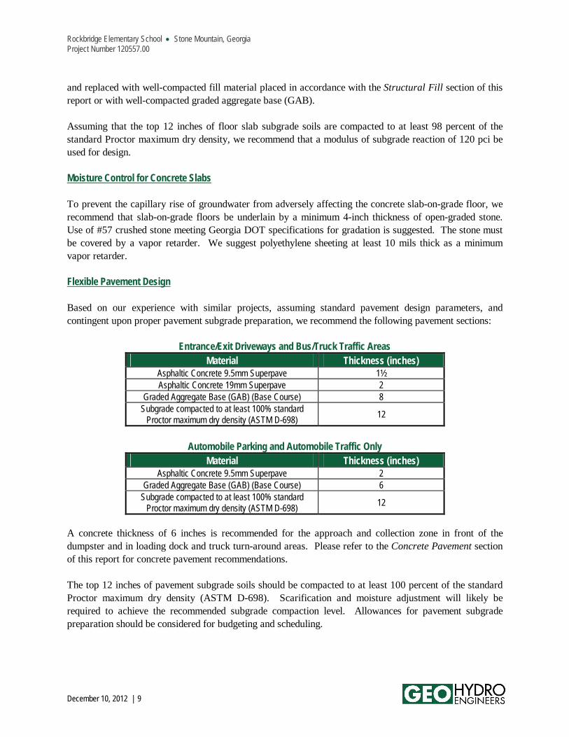
Flexible Pavement Design Based on our experience with similar projects, assuming standard pavement design parameters, and contingent upon proper pavement subgrade preparation, we recommend the following pavement sections:
Entrance/Exit Driveways and Bus/Truck Traffic Areas Material Thickness (inches)
Asphaltic Concrete 9.5mm Superpave 1½ Asphaltic Concrete 19mm Superpave 2
Graded Aggregate Base (GAB) (Base Course) 8 Subgrade compacted to at least 100% standard
Proctor maximum dry density (ASTM D-698) 12
Automobile Parking and Automobile Traffic Only
Material Thickness (inches) Asphaltic Concrete 9.5mm Superpave 2
Graded Aggregate Base (GAB) (Base Course) 6 Subgrade compacted to at least 100% standard
Proctor maximum dry density (ASTM D-698) 12
A concrete thickness of 6 inches is recommended for the approach and collection zone in front of the dumpster and in loading dock and truck turn-around areas. Please refer to the Concrete Pavement section of this report for concrete pavement recommendations. The top 12 inches of pavement subgrade soils should be compacted to at least 100 percent of the standard Proctor maximum dry density (ASTM D-698). Scarification and moisture adjustment will likely be required to achieve the recommended subgrade compaction level. Allowances for pavement subgrade preparation should be considered for budgeting and scheduling.
Rockbridge Elementary School Stone Mountain, Georgia Project Number 120557.00
December 10, 2012 | 10
GAB must be compacted to at least 100 percent of the modified Proctor maximum dry density (ASTM D-1557). All pavement construction should be performed in general accordance with Georgia DOT specifications. Proper subgrade compaction, adherence to Georgia DOT specifications, and compliance with project plans and specifications, will be critical to the performance of the constructed pavement. Concrete Pavement A rigid portland cement concrete pavement may be considered. Although usually more costly, a portland cement concrete pavement is typically more durable and requires less maintenance throughout the life cycle of the facility. Concrete thicknesses of 5 inches in automobile parking areas and 6 inches in driveways and truck traffic areas are recommended. A concrete thickness of 6 inches is recommended for the approach and collection zone in front of the dumpster and loading dock and in truck turn-around areas. A 650-psi flexural strength concrete mix with 4 to 6 percent air entrainment should be used. The concrete pavement should be underlain by no less than 4 inches of compacted graded aggregate base (GAB). GAB should be compacted to at least 100 percent of the modified Proctor maximum dry density (ASTM D-1557). The top 12 inches of soil subgrade should be compacted to at least 100 percent of the standard Proctor maximum dry density (ASTM D-698). The concrete pavement may be designed as a “plain concrete pavement” with no reinforcing steel, or reinforcing steel may be used at joints. Construction joints and other design details should be in accordance with guidelines provided by the Portland Cement Association and the American Concrete Institute. In general, all pavement construction should be in accordance with Georgia DOT specifications. Proper subgrade compaction, adherence to Georgia DOT specifications, and compliance with project plans and specifications will be critical to the performance of the constructed pavement. Pavement Design Limitations The pavement sections discussed above are based on our experience with similar projects and are preliminary. After traffic information has been developed, we recommend that you allow us to review the traffic data and revise our recommendations as necessary. Pavement Materials Testing In order to aid in verifying that the pavement system is installed in general accordance with the design considerations, the following materials testing services are recommended:
Density testing of subgrade materials.
Proofrolling of pavement subgrade materials immediately prior to placement of graded aggregate base
(GAB). This proofrolling should be performed the same day GAB is installed.
Rockbridge Elementary School Stone Mountain, Georgia Project Number 120557.00
December 10, 2012 | 11
Density testing of GAB and verification of GAB thickness. In-place density should be verified using the sand cone method (ASTM D-1556).
Coring of the pavement to verify thickness and density (asphalt pavement only). Three cores should suffice to evaluate the finished pavement.
Preparation and testing of beams and cylinders for flexural and compressive strength testing (portland cement concrete only). The total number of test specimens required will depend on the number of concrete placement events necessary to construct the pavement.
Supplemental Exploration Due to the preliminary nature of this subsurface exploration, we recommend that a supplemental geotechnical exploration be performed when foundation loads and site grading are known. A supplemental exploration will help to further evaluate subsurface conditions and the impact of subsurface conditions on site development.
* * * * * *
We appreciate the opportunity to serve as your geotechnical consultant for this project, and are prepared to provide any additional services you may require. If you have any questions concerning this report or any of our services, please call us. Sincerely, GEO-HYDRO ENGINEERS, INC. Brian K. Ingram, P.E. Luis E. Babler, P.E. Senior Geotechnical Engineer Chief Engineer [email protected] [email protected]
BKI/LEB/120557.00 Rockbridge Elem Report

APPENDIX
I:Main/Geo/Misc/Symbols&Nomenclature
Symbols and Nomenclature Symbols ▐ Thin-walled tube (TWT) sample recovered
Thin-walled tube (TWT) sample not recovered
● Standard penetration resistance (ASTM D1586)
50/2” Number of blows (50) to drive the split-spoon a number of inches (2)
65% Percentage of rock core recovered
RQD Rock quality designation - % of recovered core sample which is 4 or more inches long
GW Groundwater
Water level at least 24 hours after drilling
Water level one hour or less after drilling
ALLUV Alluvium
TOP Topsoil
PM Pavement Materials
CONC Concrete
FILL Fill Material
RES Residual Soil
PWR Partially Weathered Rock
SPT Standard Penetration Testing Penetration Resistance Results Approximate Number of Blows, N Relative Density Sands 0-4 very loose
5-10 loose 11-20 firm 21-30 very firm 31-50 dense Over 50 very dense
Approximate Number of Blows, N Consistency Silts and 0-1 very soft Clays 2-4 soft 5-8 firm 9-15 stiff 16-30 very stiff 31-50 hard Over 50 very hard Drilling Procedures Soil sampling and standard penetration testing performed in accordance with ASTM D 1586. The standard penetration resistance is the number of blows of a 140-pound hammer falling 30 inches to drive a 2-inch O.D., 1.4-inch I.D. split-spoon sampler one foot. Rock coring is performed in accordance with ASTM D 2113. Thin-walled tube sampling is performed in accordance with ASTM D 1587.
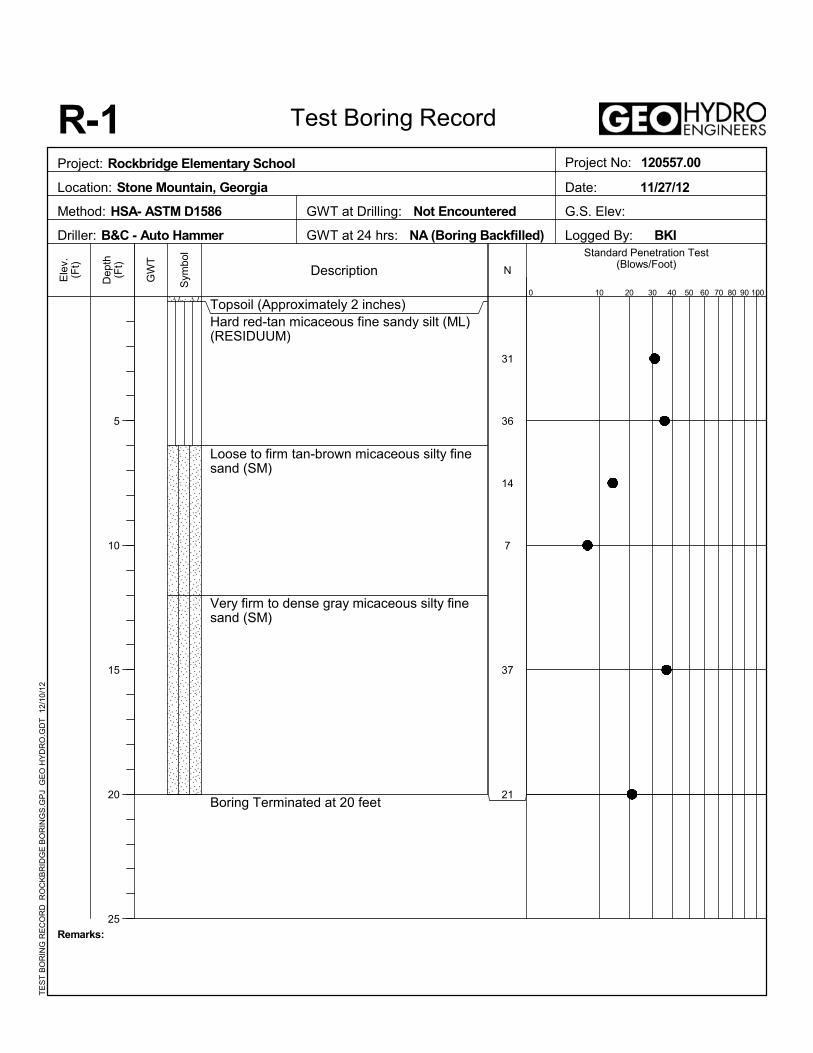
31
36
14
7
37
21
Topsoil (Approximately 2 inches)Hard red-tan micaceous fine sandy silt (ML)(RESIDUUM)
Loose to firm tan-brown micaceous silty finesand (SM)
Very firm to dense gray micaceous silty finesand (SM)
Boring Terminated at 20 feet
90
Ele
v.(F
t)
Remarks:
GWT at 24 hrs: NA (Boring Backfilled)
N
0
R-1
30 40 100
Sym
bol
10
Standard Penetration Test(Blows/Foot)
Test Boring Record
Description
Dep
th(F
t)
5
10
15
20
25
GW
T
60
GWT at Drilling: Not Encountered
50 70
Date: 11/27/12
Logged By: BKI
8020
G.S. Elev:Method: HSA- ASTM D1586
Project No: 120557.00Project: Rockbridge Elementary School
Location: Stone Mountain, Georgia
Driller: B&C - Auto Hammer
TE
ST
BO
RIN
G R
EC
OR
D R
OC
KB
RID
GE
BO
RIN
GS
.GP
J G
EO
HY
DR
O.G
DT
12
/10
/12
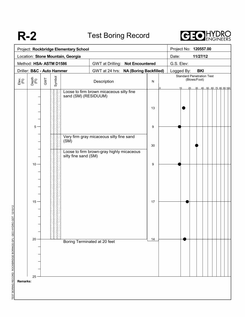
13
9
30
9
17
14
Loose to firm brown micaceous silty finesand (SM) (RESIDUUM)
Very firm gray micaceous silty fine sand(SM)
Loose to firm brown-gray highly micaceoussilty fine sand (SM)
Boring Terminated at 20 feet
90
Ele
v.(F
t)
Remarks:
GWT at 24 hrs: NA (Boring Backfilled)
N
0
R-2
30 40 100
Sym
bol
10
Standard Penetration Test(Blows/Foot)
Test Boring Record
Description
Dep
th(F
t)
5
10
15
20
25
GW
T
60
GWT at Drilling: Not Encountered
50 70
Date: 11/27/12
Logged By: BKI
8020
G.S. Elev:Method: HSA- ASTM D1586
Project No: 120557.00Project: Rockbridge Elementary School
Location: Stone Mountain, Georgia
Driller: B&C - Auto Hammer
TE
ST
BO
RIN
G R
EC
OR
D R
OC
KB
RID
GE
BO
RIN
GS
.GP
J G
EO
HY
DR
O.G
DT
12
/10
/12
13
15
10
8
8
29
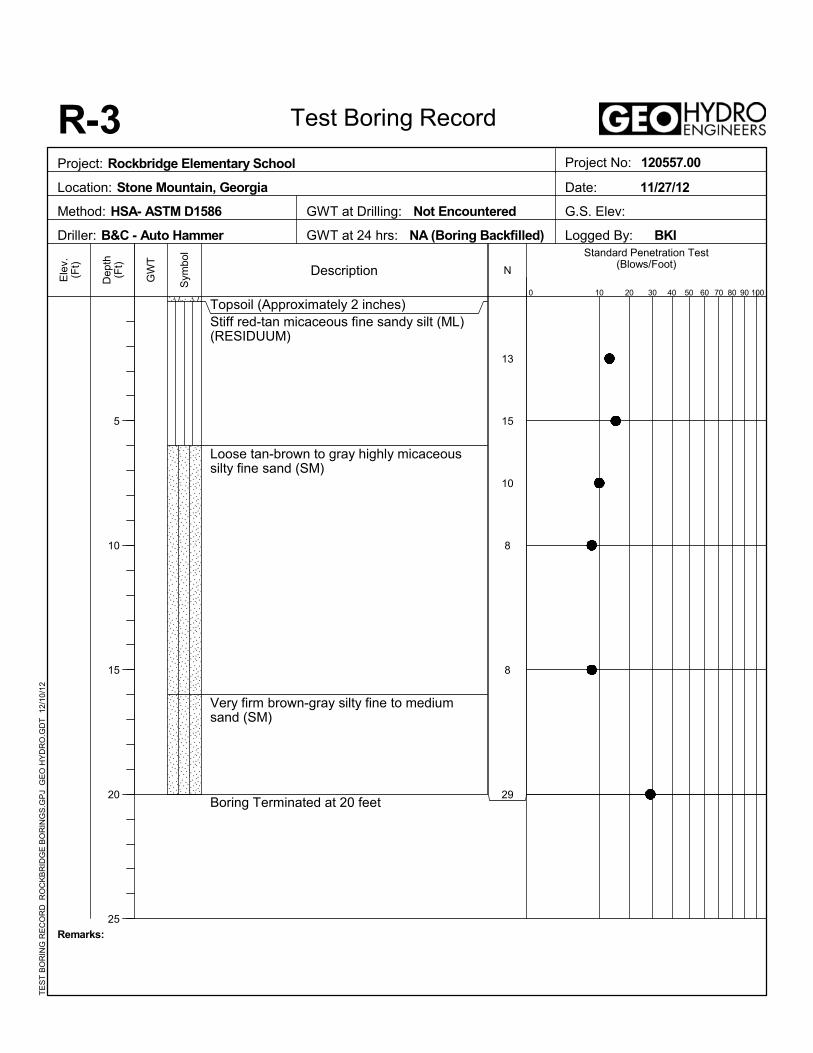
Topsoil (Approximately 2 inches)Stiff red-tan micaceous fine sandy silt (ML)(RESIDUUM)
Loose tan-brown to gray highly micaceoussilty fine sand (SM)
Very firm brown-gray silty fine to mediumsand (SM)
Boring Terminated at 20 feet
90
Ele
v.(F
t)
Remarks:
GWT at 24 hrs: NA (Boring Backfilled)
N
0
R-3
30 40 100
Sym
bol
10
Standard Penetration Test(Blows/Foot)
Test Boring Record
Description
Dep
th(F
t)
5
10
15
20
25
GW
T
60
GWT at Drilling: Not Encountered
50 70
Date: 11/27/12
Logged By: BKI
8020
G.S. Elev:Method: HSA- ASTM D1586
Project No: 120557.00Project: Rockbridge Elementary School
Location: Stone Mountain, Georgia
Driller: B&C - Auto Hammer
TE
ST
BO
RIN
G R
EC
OR
D R
OC
KB
RID
GE
BO
RIN
GS
.GP
J G
EO
HY
DR
O.G
DT
12
/10
/12
12
12
7
7
10
33
Topsoil (Approximately 2 inches)Stiff red-tan slightly micaceous fine sandy silt(ML) (FILL)
Stiff tan-brown fine sandy silt (ML)(RESIDUUM)
Loose tan to gray highly micaceous silty finesand (SM)
Dense gray highly micaceous silty fine sand(SM)
Boring Terminated at 20 feet
90
Ele
v.(F
t)
Remarks:
GWT at 24 hrs: NA (Boring Backfilled)
N
0
R-4
30 40 100
Sym
bol
10
Standard Penetration Test(Blows/Foot)
Test Boring Record
Description
Dep
th(F
t)
5
10
15
20
25
GW
T
60
GWT at Drilling: Not Encountered
50 70
Date: 11/27/12
Logged By: BKI
8020
G.S. Elev:Method: HSA- ASTM D1586
Project No: 120557.00Project: Rockbridge Elementary School
Location: Stone Mountain, Georgia
Driller: B&C - Auto Hammer
TE
ST
BO
RIN
G R
EC
OR
D R
OC
KB
RID
GE
BO
RIN
GS
.GP
J G
EO
HY
DR
O.G
DT
12
/10
/12
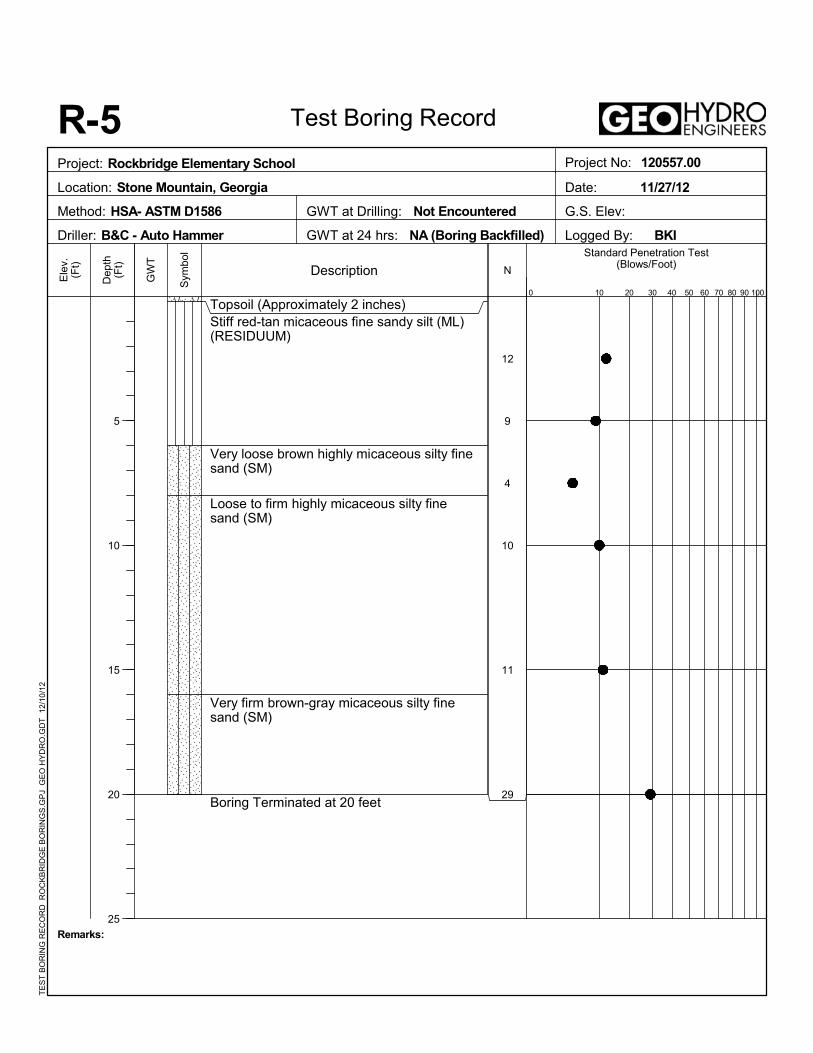
12
9
4
10
11
29
Topsoil (Approximately 2 inches)Stiff red-tan micaceous fine sandy silt (ML)(RESIDUUM)
Very loose brown highly micaceous silty finesand (SM)
Loose to firm highly micaceous silty finesand (SM)
Very firm brown-gray micaceous silty finesand (SM)
Boring Terminated at 20 feet
90
Ele
v.(F
t)
Remarks:
GWT at 24 hrs: NA (Boring Backfilled)
N
0
R-5
30 40 100
Sym
bol
10
Standard Penetration Test(Blows/Foot)
Test Boring Record
Description
Dep
th(F
t)
5
10
15
20
25
GW
T
60
GWT at Drilling: Not Encountered
50 70
Date: 11/27/12
Logged By: BKI
8020
G.S. Elev:Method: HSA- ASTM D1586
Project No: 120557.00Project: Rockbridge Elementary School
Location: Stone Mountain, Georgia
Driller: B&C - Auto Hammer
TE
ST
BO
RIN
G R
EC
OR
D R
OC
KB
RID
GE
BO
RIN
GS
.GP
J G
EO
HY
DR
O.G
DT
12
/10
/12
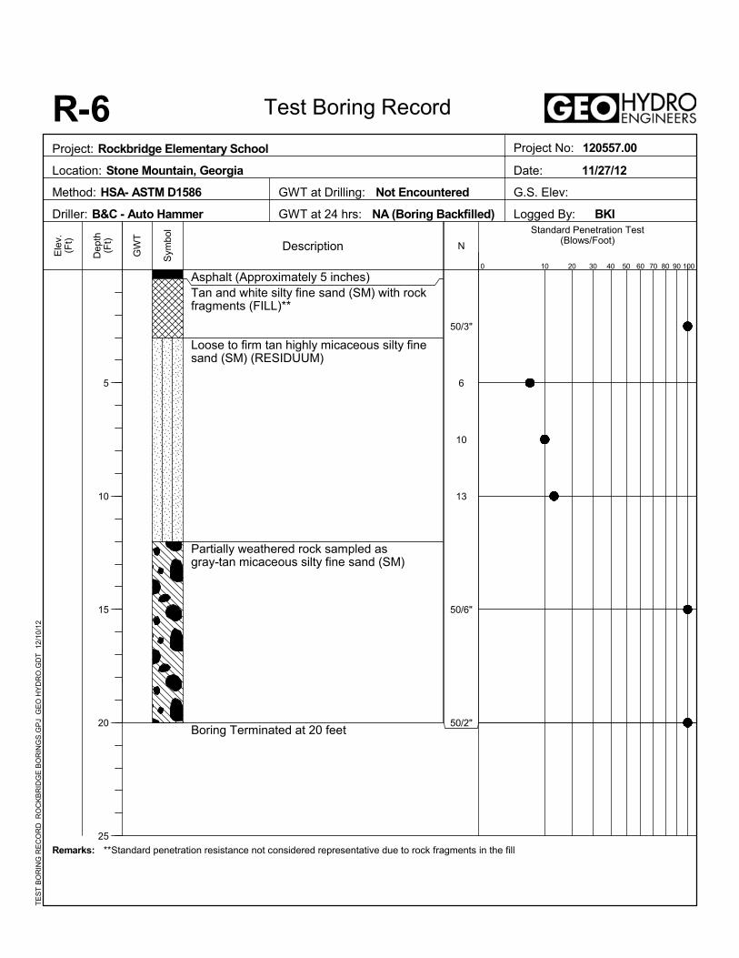
50/3"
6
10
13
50/6"
50/2"
Asphalt (Approximately 5 inches)Tan and white silty fine sand (SM) with rockfragments (FILL)**
Loose to firm tan highly micaceous silty finesand (SM) (RESIDUUM)
Partially weathered rock sampled asgray-tan micaceous silty fine sand (SM)
Boring Terminated at 20 feet
90
Ele
v.(F
t)
Remarks:
GWT at 24 hrs: NA (Boring Backfilled)
**Standard penetration resistance not considered representative due to rock fragments in the fill
N
0
R-6
30 40 100
Sym
bol
10
Standard Penetration Test(Blows/Foot)
Test Boring Record
Description
Dep
th(F
t)
5
10
15
20
25
GW
T
60
GWT at Drilling: Not Encountered
50 70
Date: 11/27/12
Logged By: BKI
8020
G.S. Elev:Method: HSA- ASTM D1586
Project No: 120557.00Project: Rockbridge Elementary School
Location: Stone Mountain, Georgia
Driller: B&C - Auto Hammer
TE
ST
BO
RIN
G R
EC
OR
D R
OC
KB
RID
GE
BO
RIN
GS
.GP
J G
EO
HY
DR
O.G
DT
12
/10
/12
10
10
4
68
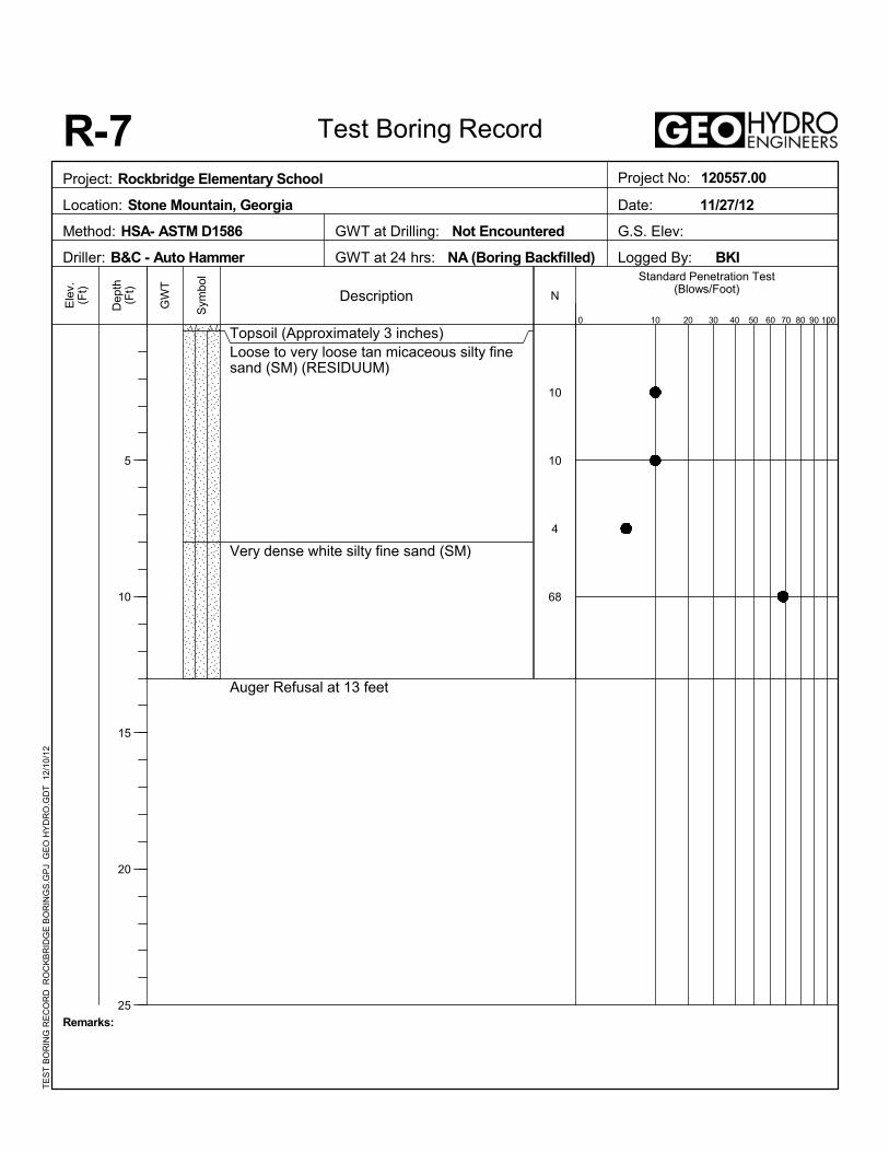
Topsoil (Approximately 3 inches)Loose to very loose tan micaceous silty finesand (SM) (RESIDUUM)
Very dense white silty fine sand (SM)
Auger Refusal at 13 feet
90
Ele
v.(F
t)
Remarks:
GWT at 24 hrs: NA (Boring Backfilled)
N
0
R-7
30 40 100
Sym
bol
10
Standard Penetration Test(Blows/Foot)
Test Boring Record
Description
Dep
th(F
t)
5
10
15
20
25
GW
T
60
GWT at Drilling: Not Encountered
50 70
Date: 11/27/12
Logged By: BKI
8020
G.S. Elev:Method: HSA- ASTM D1586
Project No: 120557.00Project: Rockbridge Elementary School
Location: Stone Mountain, Georgia
Driller: B&C - Auto Hammer
TE
ST
BO
RIN
G R
EC
OR
D R
OC
KB
RID
GE
BO
RIN
GS
.GP
J G
EO
HY
DR
O.G
DT
12
/10
/12
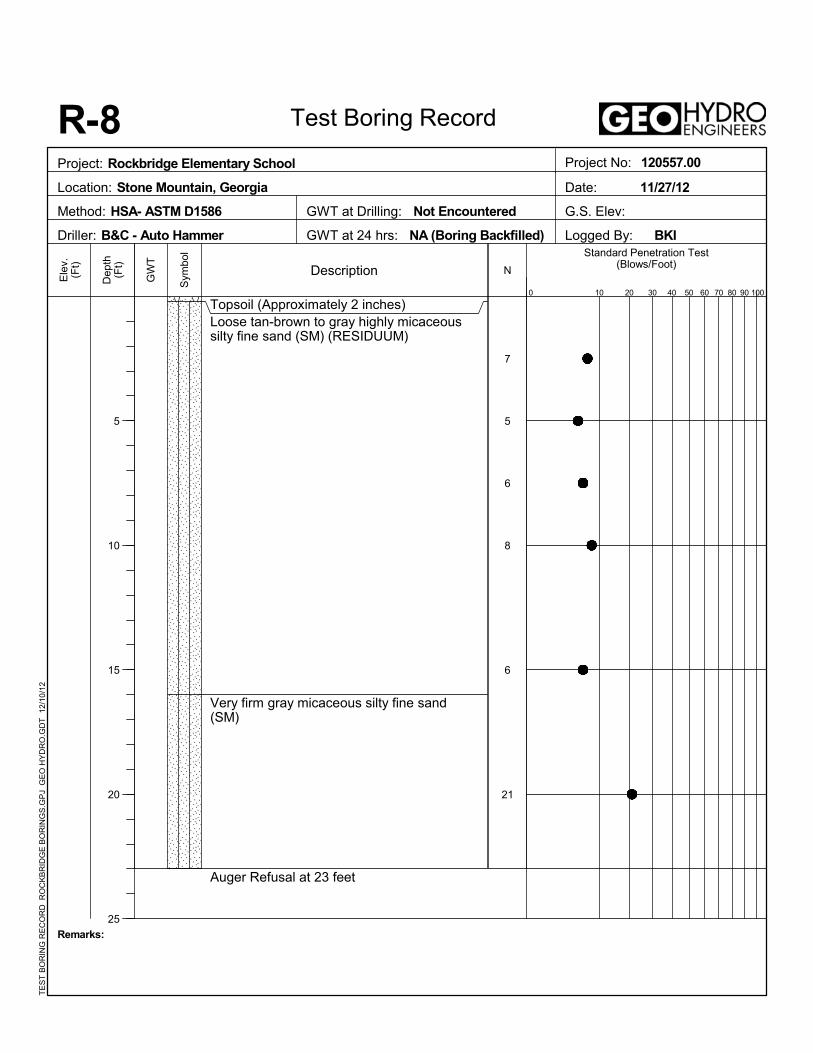
7
5
6
8
6
21
Topsoil (Approximately 2 inches)Loose tan-brown to gray highly micaceoussilty fine sand (SM) (RESIDUUM)
Very firm gray micaceous silty fine sand(SM)
Auger Refusal at 23 feet
90
Ele
v.(F
t)
Remarks:
GWT at 24 hrs: NA (Boring Backfilled)
N
0
R-8
30 40 100
Sym
bol
10
Standard Penetration Test(Blows/Foot)
Test Boring Record
Description
Dep
th(F
t)
5
10
15
20
25
GW
T
60
GWT at Drilling: Not Encountered
50 70
Date: 11/27/12
Logged By: BKI
8020
G.S. Elev:Method: HSA- ASTM D1586
Project No: 120557.00Project: Rockbridge Elementary School
Location: Stone Mountain, Georgia
Driller: B&C - Auto Hammer
TE
ST
BO
RIN
G R
EC
OR
D R
OC
KB
RID
GE
BO
RIN
GS
.GP
J G
EO
HY
DR
O.G
DT
12
/10
/12

SITE PHOTOS
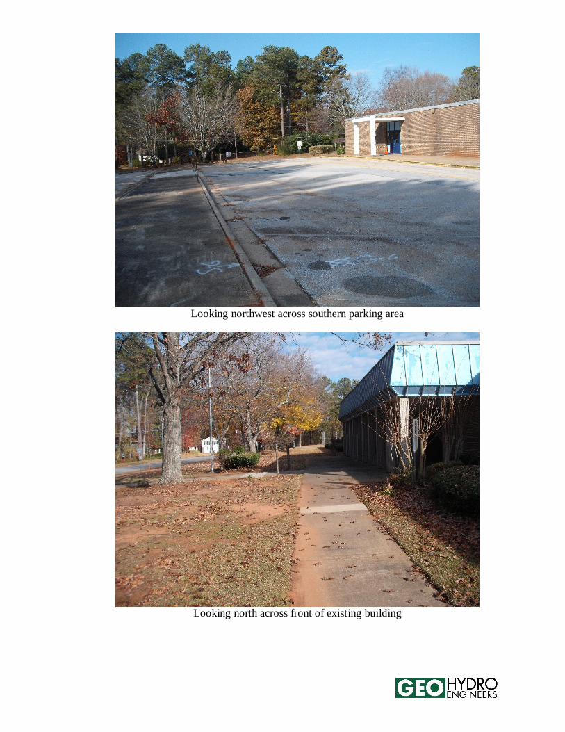
Looking northwest across southern parking area
Looking north across front of existing building
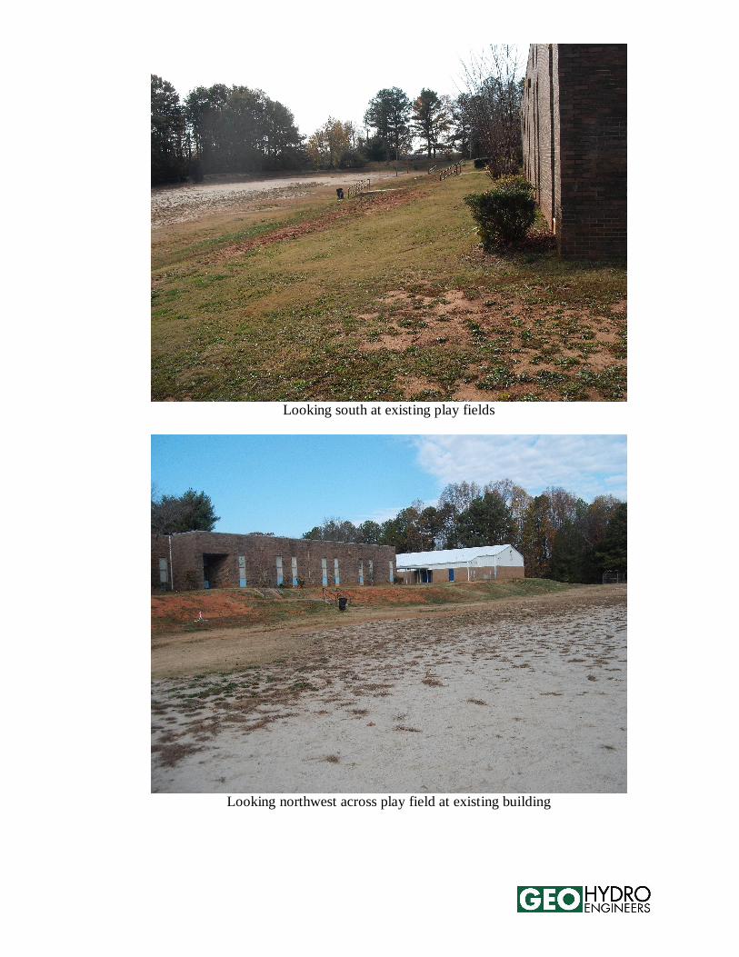
Looking south at existing play fields
Looking northwest across play field at existing building